paper no. 5927 - ohio university of h2s on... · antimony trioxide + 50 g stannous chloride and...
TRANSCRIPT

Effect of H2S on the Corrosion Behavior of Pipeline Steels in Supercritical and Liquid CO2 Environments
Yoon-Seok Choi, Shokrollah Hassani, Thanh Nam Vu, Srdjan Nesic Institute for Corrosion and Multiphase Technology,
Department of Chemical and Biomolecular Engineering, Ohio University 342 West State Street
Athens, OH 45701 USA
Ahmad Zaki B Abas
Petronas Research SDN. BHD, Selangor Darul Ehsan, Malaysia
ABSTRACT The objective of the present study is to evaluate the corrosion properties of pipeline steels in CO2/H2S/H2O mixtures with different amounts of water (under-saturated and saturated) related to a natural gas transportation pipeline. Corrosion behavior of carbon steel, 1Cr steel and 3Cr steel was evaluated by using an autoclave with different combinations of CO2 partial pressure and temperature (8 MPa/25oC and 12 MPa/80oC) with 200 ppm H2S. The corrosion rate of samples was determined by weight loss measurements. The surface morphology and the composition of the corrosion product layers were analyzed using surface analytical techniques (SEM and EDS). Results showed that the corrosion rate of materials in supercritical and liquid phase CO2 saturated with water was very low (< 0.01 mm/y). However, adding 200 ppm of H2S to the supercritical and liquid CO2 system caused mild corrosion (< 0.5 mm/y). Reducing water content to 100 ppm in the supercritical and liquid CO2 systems with 200 ppm of H2S reduced the corrosion rate to less than 0.01 mm/y. Key words: Supercritical/liquid CO2, CO2 corrosion, H2S, carbon steel, low Cr steel
INTRODUCTION
Proven gas reserves in South East Asia are estimated at 5153 billion cubic metres (bcm), with Malaysia holding a 1047 bcm share. In the past, most of these gas fields were not economically viable due to the presence of large quantities of CO2 (from 25% to 89%).1 However, as the demand for energy rapidly grew, these resources become increasingly valuable. Produced gases from such fields are usually associated with potential high corrosion risks and resultant use of expensive Corrosion Resistant Alloys (CRAs). However, there is a need to better quantify the risk of corrosion associated with high pressure CO2 environments in order to identify conditions in which mild steel may still be suitable when used with appropriate corrosion mitigation strategies. This has the potential to significantly reduce costs associated with use of CRAs for infrastructure construction.
1
Paper No.
5927
©2015 by NACE International. Requests for permission to publish this manuscript in any form, in part or in whole, must be in writing to NACE International, Publications Division, 15835 Park Ten Place, Houston, Texas 77084. The material presented and the views expressed in this paper are solely those of the author(s) and are not necessarily endorsed by the Association.

Development of such high pressure CO2 fields has to consider the presence of formation water which has the potential to contain a high concentration of corrosive species due to dissolved CO2. For offshore installations, it would be too costly to dry the gas stream or to remove CO2 gas prior to transportation of hydrocarbon gas via pipelines. Due to the direct impact of the presence of formation water and high pressure CO2 on the corrosion of pipeline steel, studies related to aqueous CO2 corrosion at high CO2 pressure have recently been conducted. It has been reported that the corrosion rate of carbon steel under high CO2 pressure (liquid and supercritical CO2) without formation of protective FeCO3 corrosion product layers is very high (≥ 20 mm/y).2-6 At certain conditions, the corrosion rate can decrease to low values (< 1 mm/y) after long-term exposures due to the formation of a protective layer of FeCO3.7-9 Usually, conventional CO2 separation technologies remove CO2 from natural gas at low pressure and release it to the atmosphere.10 However, due to the large quantities of CO2 present in the high pressure CO2 gas fields, the CO2 must be captured and transported to sequestration sites separately, which presents similar challenges as seen in CO2 transmission related to carbon capture and storage (CCS). It has been acknowledged that dry supercritical and liquid CO2 is not corrosive. However, recent studies have reported that the presence of trace impurities such as SOx and NOx can cause significant corrosion for carbon steel in supercritical and liquid CO2 in the presence of small amounts of H2O (below the solubility limit).11-18 Related to gas field development, it has recently been reported that there can be small amounts of H2S present in the high pressure CO2 streams, whereas the effect on corrosion has thus far not been studied.
Figure 1 shows a schematic of a CO2 transportation pipeline experiencing a temperature drop. At the inlet condition, the pressure is 12 MPa and temperature is 80oC. At this condition CO2 is in the supercritical phase. Along the pipeline the temperature drops and consequently pressure drops and the CO2 transitions from supercritical to liquid phase. Supercritical CO2 at a pressure of 12 MPa and temperature of 80oC can dissolve 10,000 ppm of water.19 However, liquid CO2 at 8 MPa and 25oC can dissolve only 3,000 ppm water.19 Therefore, temperature drop and consequently CO2 phase transformation causes the formation of free water in the system.
Figure 1: Schematic of different parts of the pipeline with inlet and outlet conditions.
Thus, the objective of the present study was to evaluate the corrosion performance of pipeline steels in supercritical and liquid CO2 phases with and without temperature fluctuations and water condensation and also with and without H2S. Corrosion behavior of carbon steel, 1Cr steel and 3Cr steel was evaluated using an autoclave with different combinations of CO2 partial pressure and temperature (8 MPa/25oC and 12 MPa/80oC) at a 200 ppm H2S concentration.
2
©2015 by NACE International. Requests for permission to publish this manuscript in any form, in part or in whole, must be in writing to NACE International, Publications Division, 15835 Park Ten Place, Houston, Texas 77084. The material presented and the views expressed in this paper are solely those of the author(s) and are not necessarily endorsed by the Association.

EXPERIMENTAL PROCEDURE
The materials used in this work are as follow:
UNS K03014 carbon steel, named CS
UNS G41300-1Cr steel, named 1Cr
UNS G41300-3Cr steel, named 3Cr All materials were analyzed for chemical composition using Atomic Emission Spectroscopy (AES). Table 1 shows chemical compositions of the three materials used in the present study.
Table 1 Chemical compositions of materials used in the present study (wt.%, balance Fe).
C Cr Mn P S Si Cu Ni Mo Al
CS 0.065 0.05 1.54 0.013 0.001 0.25 0.04 0.04 0.007 0.041
1Cr 0.3 0.85 0.91 0.015 0.008 0.29 --- --- --- ---
3Cr 0.08 3.43 0.54 0.006 0.003 0.3 0.16 0.06 0.32 ---
The specimens for the corrosion tests were machined to be rectangular with a size of 1.27 cm × 1.27 cm × 0.254 cm. A 5 mm diameter hole at one end serves to hang the samples from a sample stand with a non-metallic washer. The specimens were ground with 600-grit silicon carbide (SiC) paper, cleaned with isopropyl alcohol (i-C3H7OH) in an ultrasonic bath, dried, and weighed using a balance with a precision of 0.1 mg. The corrosion experiments were carried out in a 7.5-liter autoclave (UNS N10276). The electrolyte was a 1 wt.% NaCl solution. In the present study, the corrosion behavior of materials was evaluated in CO2-rich phase (Figure 2), where samples were located in the CO2 phase. Water content at the bottom of the autoclave was varied in correspondence with the water concentration in the CO2 phase. Once sealed, the autoclave temperature was adjusted. Then, a mixture of CO2 and H2S was directly injected into the autoclave to the desired H2S concentration (200 ppm). Finally, high pressure CO2 was added to the autoclave with a gas booster pump to the desired working pressure.
Figure 2: Schematic of specimen location in the autoclave.
3
©2015 by NACE International. Requests for permission to publish this manuscript in any form, in part or in whole, must be in writing to NACE International, Publications Division, 15835 Park Ten Place, Houston, Texas 77084. The material presented and the views expressed in this paper are solely those of the author(s) and are not necessarily endorsed by the Association.
The corrosion rates were determined from the weight-loss method at the end of the test. In each test, two specimens were simultaneously exposed to the corrosive environment in order to obtain an averaged corrosion rate. The specimens were removed and cleaned for 5 min in Clarke solution (20 g antimony trioxide + 50 g stannous chloride and hydrochloric acid to make 1000 ml). The specimens were then rinsed in distilled water, dried and weighed to 0.1 mg. The average corrosion rate during the test period can be calculated by the following equation:20
(hour) time)(g/cmdensity )(cm area
(g) loss weightyearhour/cmmm108.76(mm/y) rate Corrosion
32
4
)( (1)
The morphology and compositions of corrosion products were analyzed using scanning electron microscopy (SEM) and energy dispersive X-ray spectroscopy (EDS). Corrosion in CO2 Phase without Water Condensation
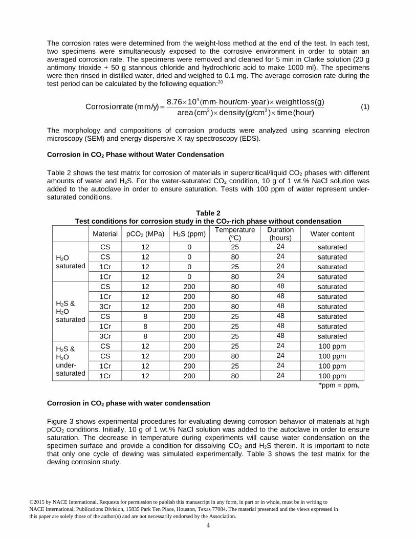
Table 2 shows the test matrix for corrosion of materials in supercritical/liquid CO2 phases with different amounts of water and H2S. For the water-saturated CO2 condition, 10 g of 1 wt.% NaCl solution was added to the autoclave in order to ensure saturation. Tests with 100 ppm of water represent under-saturated conditions.
Table 2 Test conditions for corrosion study in the CO2-rich phase without condensation
Material pCO2 (MPa) H2S (ppm) Temperature
(oC) Duration (hours)
Water content
H2O saturated
CS 12 0 25 24 saturated
CS 12 0 80 24 saturated
1Cr 12 0 25 24 saturated
1Cr 12 0 80 24 saturated
H2S & H2O saturated
CS 12 200 80 48 saturated
1Cr 12 200 80 48 saturated
3Cr 12 200 80 48 saturated
CS 8 200 25 48 saturated
1Cr 8 200 25 48 saturated
3Cr 8 200 25 48 saturated
H2S & H2O under-saturated
CS 12 200 25 24 100 ppm
CS 12 200 80 24 100 ppm
1Cr 12 200 25 24 100 ppm
1Cr 12 200 80 24 100 ppm
*ppm = ppmv
Corrosion in CO2 phase with water condensation
Figure 3 shows experimental procedures for evaluating dewing corrosion behavior of materials at high pCO2 conditions. Initially, 10 g of 1 wt.% NaCl solution was added to the autoclave in order to ensure saturation. The decrease in temperature during experiments will cause water condensation on the specimen surface and provide a condition for dissolving CO2 and H2S therein. It is important to note that only one cycle of dewing was simulated experimentally. Table 3 shows the test matrix for the dewing corrosion study.
4
©2015 by NACE International. Requests for permission to publish this manuscript in any form, in part or in whole, must be in writing to NACE International, Publications Division, 15835 Park Ten Place, Houston, Texas 77084. The material presented and the views expressed in this paper are solely those of the author(s) and are not necessarily endorsed by the Association.

Time
Increase T & P
Prepare solution /
purge with CO2
Place steel
samples in CO2
phase Turn off heater
2 hours 12 hours 24 hours
80oC, 120 bar 25
oC, 70 bar
Figure 3: Experimental procedures for evaluating the dewing corrosion behavior of materials in
high pCO2 environments with H2S.
Table 3 Test conditions for dewing corrosion study
Material pCO2 (MPa) H2S (ppm) Temperature (oC) Water content
Dewing
CS 12 0 80 → 25 saturated
1Cr 12 0 80 → 25 saturated
3Cr 12 0 80 → 25 saturated
CS 12 200 80 → 25 saturated
1Cr 12 200 80 → 25 saturated
3Cr 12 200 80 → 25 saturated
*ppm = ppmv
RESULTS AND DISCUSSION Corrosion in CO2 phase without water condensation
Table 4 shows the summary of corrosion rate data of three different steels in the supercritical CO2 phase (inlet condition) and liquid CO2 phase (outlet condition) with and without H2S. Experimental data shows that corrosion rate in supercritical and liquid CO2 phases saturated with water is very low (< 0.01 mm/y), consistent with previous results.11,12,21,22 However, adding H2S to the supercritical and liquid CO2 systems leads to corrosion. Furthermore, reducing water content to 100 ppm in supercritical and liquid CO2 systems with 200 ppm H2S reduced the corrosion rate to less than 0.01 mm/yr. Figure 4 and Figure 5 show SEM images and EDS spectra of the corroded CS sample surface and cross-section, exposed to water-saturated supercritical CO2 (12 MPa, 80oC) with 200 ppm of H2S. As shown in Figure 4, the surface was covered by corrosion products that consisted of Fe and S. This indicates the formation of FeS on the steel surface under this condition. Furthermore, it can be seen from Figure 5 that it has a bilayer structure; an outer thin FeS layer and a thick/continuous inner FeCO3 layer. A similar morphology was observed for 1Cr steel. Figure 6 shows the SEM image and EDS spectra of the corroded surface of 3Cr steel after exposure to water-saturated supercritical CO2 (12 MPa, 80oC) with 200 ppm of H2S. It can be seen that the surface was covered by a thin layer of sulfur-containing corrosion products. Note that the polishing marks are still visible, indicating that the corrosion of this material was minimal, compare to CS and 1Cr steel.
5
©2015 by NACE International. Requests for permission to publish this manuscript in any form, in part or in whole, must be in writing to NACE International, Publications Division, 15835 Park Ten Place, Houston, Texas 77084. The material presented and the views expressed in this paper are solely those of the author(s) and are not necessarily endorsed by the Association.

Table 4 Summary of corrosion rate data of three different steels in CO2 phase
Material
pCO2 (MPa)
H2S (ppm)
Temp. (oC)
Water content
Corrosion Rate (mm/y)
H2O saturated
CS 12 --- 25 saturated < 0.01
CS 12 --- 80 saturated < 0.01
1Cr 12 --- 25 saturated < 0.01
1Cr 12 --- 80 saturated < 0.01
H2S & H2O saturated
CS 12 200 80 saturated 0.41
1Cr 12 200 80 saturated 0.44
3Cr 12 200 80 saturated 0.05
CS 8 200 25 saturated 0.07
1Cr 8 200 25 saturated 0.13
3Cr 8 200 25 saturated 0.14
H2S & H2O under-saturated
CS 12 200 25 100 ppm < 0.01
CS 12 200 80 100 ppm < 0.01
1Cr 12 200 25 100 ppm < 0.01
1Cr 12 200 80 100 ppm < 0.01
Figure 4: SEM image and EDS spectra of the surface of CS after exposure to water-saturated supercritical CO2 (12 MPa, 80oC) with 200 ppm of H2S.
6
©2015 by NACE International. Requests for permission to publish this manuscript in any form, in part or in whole, must be in writing to NACE International, Publications Division, 15835 Park Ten Place, Houston, Texas 77084. The material presented and the views expressed in this paper are solely those of the author(s) and are not necessarily endorsed by the Association.

Figure 5: SEM image and EDS spectra of the cross-section of CS after exposing to water-saturated supercritical CO2 (12 MPa, 80oC) with 200 ppm of H2S
Figure 6: SEM image and EDS spectra of the surface of 3Cr steel after exposing to water-saturated supercritical CO2 (12 MPa, 80oC) with 200 ppm of H2S.
Figure 7 shows SEM images and EDS line scanning results of the corroded samples (CS, 1Cr and 3Cr steels) for their surfaces and in cross-section after exposure to water-saturated supercritical CO2 (8 MPa, 25oC) with 200 ppm of H2S. SEM surface analysis shows a similar morphology for corrosion products for all three steels. EDS elemental analysis shows that the corrosion product layer is mostly FeS. EDS line scanning also shows that for 3Cr steel there is a chromium rich layer close to the metal surface and underneath the FeS layer. This chromium rich layer reduces the adherence of corrosion products to the metal surface and, consequently, reduces the protectiveness of the corrosion product layer and increases the corrosion rate. It is interesting to note that under this low temperature condition (25oC), FeCO3 was not observed on the surface of the CS and 1Cr steel.
7
©2015 by NACE International. Requests for permission to publish this manuscript in any form, in part or in whole, must be in writing to NACE International, Publications Division, 15835 Park Ten Place, Houston, Texas 77084. The material presented and the views expressed in this paper are solely those of the author(s) and are not necessarily endorsed by the Association.
CS 1Cr 3Cr
Figure 7: SEM and EDS analyses of three different steels after corrosion experiments in liquid
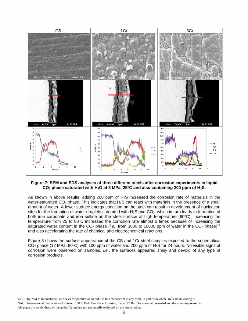
CO2 phase saturated with H2O at 8 MPa, 25oC and also containing 200 ppm of H2S. As shown in above results, adding 200 ppm of H2S increased the corrosion rate of materials in the water-saturated CO2 phase. This indicates that H2S can react with materials in the presence of a small amount of water. A lower surface energy condition on the steel can result in development of nucleation sites for the formation of water droplets saturated with H2S and CO2, which in turn leads to formation of both iron carbonate and iron sulfide on the steel surface at high temperature (80oC). Increasing the temperature from 25 to 80oC increased the corrosion rate almost 5 times because of increasing the saturated water content in the CO2 phase (i.e., from 3000 to 10000 ppm of water in the CO2 phase)19 and also accelerating the rate of chemical and electrochemical reactions. Figure 8 shows the surface appearance of the CS and 1Cr steel samples exposed to the supercritical CO2 phase (12 MPa, 80oC) with 100 ppm of water and 200 ppm of H2S for 24 hours. No visible signs of corrosion were observed on samples, i.e., the surfaces appeared shiny and devoid of any type of corrosion products.
8
©2015 by NACE International. Requests for permission to publish this manuscript in any form, in part or in whole, must be in writing to NACE International, Publications Division, 15835 Park Ten Place, Houston, Texas 77084. The material presented and the views expressed in this paper are solely those of the author(s) and are not necessarily endorsed by the Association.
(a) (b)
Figure 8: SEM images of the sample surface exposed to the supercritical CO2 phase (12 MPa,
80oC) with 100 ppm of water and 200 ppm of H2S for 24 hours: (a) CS, (b) 1Cr steel.
Corrosion in CO2 phase with water condensation (Dewing Corrosion)
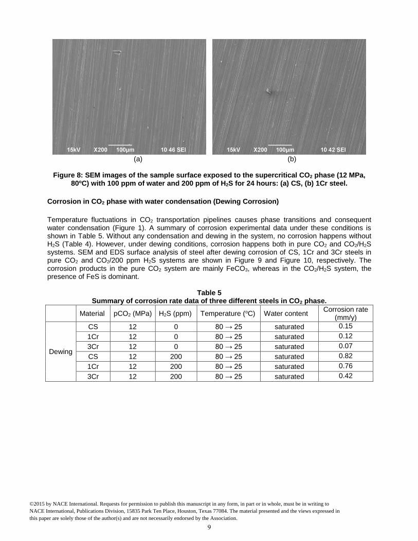
Temperature fluctuations in CO2 transportation pipelines causes phase transitions and consequent water condensation (Figure 1). A summary of corrosion experimental data under these conditions is shown in Table 5. Without any condensation and dewing in the system, no corrosion happens without H2S (Table 4). However, under dewing conditions, corrosion happens both in pure CO2 and CO2/H2S systems. SEM and EDS surface analysis of steel after dewing corrosion of CS, 1Cr and 3Cr steels in pure CO2 and CO2/200 ppm H2S systems are shown in Figure 9 and Figure 10, respectively. The corrosion products in the pure CO2 system are mainly FeCO3, whereas in the CO2/H2S system, the presence of FeS is dominant.
Table 5
Summary of corrosion rate data of three different steels in CO2 phase.
Material pCO2 (MPa) H2S (ppm) Temperature (oC) Water content Corrosion rate
(mm/y)
Dewing
CS 12 0 80 → 25 saturated 0.15
1Cr 12 0 80 → 25 saturated 0.12
3Cr 12 0 80 → 25 saturated 0.07
CS 12 200 80 → 25 saturated 0.82
1Cr 12 200 80 → 25 saturated 0.76
3Cr 12 200 80 → 25 saturated 0.42
9
©2015 by NACE International. Requests for permission to publish this manuscript in any form, in part or in whole, must be in writing to NACE International, Publications Division, 15835 Park Ten Place, Houston, Texas 77084. The material presented and the views expressed in this paper are solely those of the author(s) and are not necessarily endorsed by the Association.

(a) (b)
(c)
Figure 9: SEM and EDS surface analysis of the sample surface after corrosion experiment in
CO2 phase experiencing temperature fluctuation without H2S: (a) CS, (b) 1Cr steel, (c) 3Cr steel.
10
©2015 by NACE International. Requests for permission to publish this manuscript in any form, in part or in whole, must be in writing to NACE International, Publications Division, 15835 Park Ten Place, Houston, Texas 77084. The material presented and the views expressed in this paper are solely those of the author(s) and are not necessarily endorsed by the Association.

(a) (b)
(c)
Figure 10: SEM and EDS surface analysis of the sample surface after corrosion experiment in CO2 phase experiencing temperature fluctuation with 200 ppm of H2S: (a) CS, (b) 1Cr steel, (c)
3Cr steel.
11
©2015 by NACE International. Requests for permission to publish this manuscript in any form, in part or in whole, must be in writing to NACE International, Publications Division, 15835 Park Ten Place, Houston, Texas 77084. The material presented and the views expressed in this paper are solely those of the author(s) and are not necessarily endorsed by the Association.

CONCLUSIONS The corrosion properties of pipeline steels in CO2/H2S/H2O mixtures with different amounts of water (both saturated and under-saturated) were investigated by weight loss measurements and surface analysis techniques. The following conclusions are drawn:
There was no significant corrosion attack in the supercritical and liquid CO2 phases in the presence of water (both saturated and under-saturated).
The addition of 200 ppm H2S in the CO2 phase dramatically increased the corrosion rate of all tested materials (CS, 1Cr and 3Cr steels) when CO2 was saturated with water.
Under dewing conditions, corrosion happens both in pure CO2 and CO2/H2S systems due to the formation of water droplets on the sample surface.
3Cr steel showed better corrosion resistance for the tested conditions compared with CS and 1Cr steel.
REFERENCES
1. J. Veron, "An overview of the non-developed gas reserves in Southeast Asia," PetroMin (2007): p.
22. 2. M.F. Mohamed, A. Mohammed Nor, M.F. Suhor, M. Singer, Y.S. Choi and S. Nesic, "Water
Chemistry for Corrosion Prediction in High-pressure CO2 Environments," CORROSION 2011, paper no. 11375 (Houston, TX: NACE, 2011).
3. A. Mohammed Nor, M.F. Suhor, M.F. Mohamed, M. Singer and S. Nesic, "Corrosion of Carbon Steel in High CO2 Environment: Flow Effect," CORROSION 2011, paper no. 11245 (Houston, TX: NACE, 2011).
4. Y. Zhang, X. Pang, S. Qu, X. Li, K. Gao, “The Relationship Between Fracture Toughness of CO2
Corrosion Scale and Corrosion Rate of X65 Pipeline Steel Under Supercritical CO2 Condition,” International Journal of Greenhouse Gas Control 5 (2011): p. 1643.
5. A. Mohammad Nor, M.F. Suhor, M.F. Mohamed, M. Singer, S. Nesic, “Corrosion of Carbon Steel in High CO2 Containing Environments: the Effect of High Flow Rate,” CORROSION 2012, paper no. 0001683 (Houston, TX: NACE, 2012).
6. Y.S. Choi, D. Young, S. Nesic, L.G.S. Gray, “Wellbore Integrity and Corrosion of Carbon Steel in CO2 Geologic Storage Environments: A Literature Review,” International Journal of Greenhouse Gas Control 16S (2013): p. S70.
7. M.F. Suhor, M.F. Mohamed, A. Mohammad Nor, M. Singer, S. Nesic, “Corrosion of Mild Steel in High CO2 Environment: Effect of the FeCO3 Layer,” CORROSION 2012, paper no. 0001434 (Houston, TX: NACE, 2012).
8. Y. Zhang, X. Pang, S. Qu, X. Li, K. Gao, “Discussion of the CO2 Corrosion Mechanism Between Low Partial Pressure and Supercritical Condition,” Corrosion Science 59 (2012): p. 186.
9. Y.S. Choi, F. Farelas, S. Nesic, A.A.O. Magalhães, C. de Azevedo Andrade, “Corrosion Behavior of Deep Water Oil Production Tubing Material under Supercritical CO2 Environment: Part 1—Effect of Pressure and Temperature,” Corrosion 70 (2014): p. 38.
10. A. Hart, N. Gnanendran, “Cryogenic CO2 Capture in Natural Gas,” Energy Procedia 1 (2009): p. 697. 11. Y.S. Choi, S. Nesic, D. Young, “Effect of Impurities on the Corrosion Behavior of CO2 Transmission
Pipeline Steel in Supercritical CO2-Water Environments,” Environmental Science and Technology 44 (2010): p. 9233.
12. Y.S. Choi, S. Nesic, “Effect of Water Content on the Corrosion Behavior of Carbon Steel in Supercritical CO2 Phase with Impurities,” CORROSION 2011, paper no. 11377 (Houston, TX: NACE, 2011).
13. Y. Xiang, Z. Wang, C. Xu, C. Zhou, Z. Li, W. Ni, “Impact of SO2 Concentration of the Corrosion Rate of X70 Steel and Iron in Water-Saturated Supercritical CO2 Mixed with SO2,” J. of Supercritical Fluids 58 (2011): p. 286.
14. A.S. Ruhl, A. Kranzmann, “Corrosion in Supercritical CO2 by Diffusion of Flue Gas Acids and Water,” J. of Supercritical Fluids 68 (2012): p. 81.
12
©2015 by NACE International. Requests for permission to publish this manuscript in any form, in part or in whole, must be in writing to NACE International, Publications Division, 15835 Park Ten Place, Houston, Texas 77084. The material presented and the views expressed in this paper are solely those of the author(s) and are not necessarily endorsed by the Association.

15. A. Dugstad, M. Halseid, B. Morland, “Effect of SO2 and NO2 on Corrosion and Solid Formation in Dense Phase CO2 Pipelines,” Energy Procedia 37 (2013): p. 2877.
16. F. Farelas, Y.S. Choi, S. Nesic, “Corrosion Behavior of API 5L X65 Carbon Steel under Supercritical and Liquid CO2 Phases in the Presence of H2O and SO2,” Corrosion 69 (2013): p. 243.
17. O. Yevtushenko, D. Bettge, S. Bohraus, R. Bäß ler, A. Pfennig, A. Kranzmann, “Corrosion Behavior of Steels for CO2 Injection,” Process Safety and Environmental Protection 92 (2014): p. 108.
18. S. Sim, I.S. Cole, Y.S. Choi, N. Birbilis, “A Review of the Protection Strategies against Internal Corrosion for the Safe Transport of Supercritical CO2 via Steel Pipelines for CCS Purposes,” International Journal of Greenhouse Gas Control 29 (2014): p. 185.
19. Y. S. Choi, S. Nesic, “Determining the Corrosive Potential of CO2 Transport Pipeline in High pCO2–Water Environments,” International Journal of Greenhouse Gas Control 5 (2011): p. 788.
20. ASTM Standard G31, “Standard Practice for Laboratory Immersion Corrosion Testing of Metals,” in Annual Book of ASTM Standards, vol. 03. 02 (West Conshohocken, PA: ASTM International, 1994)
21. S. Sim, F. Bocher, I.S. Cole, X.B. Chen, N. Birbilis, “Investigating the Effect of Water Content in Supercritical CO2 as Relevant to the Corrosion of Carbon Capture and Storage Pipelines,” Corrosion 70 (2014): p. 185.
22. Y. Hua, R. Barker, A. Neville, “Effect of Temperature on the Critical Water Content for General and Localised Corrosion of X65 Carbon Steel in the Transport of Supercritical CO2,” International Journal of Greenhouse Gas Control 31 (2014): p. 48.
13
©2015 by NACE International. Requests for permission to publish this manuscript in any form, in part or in whole, must be in writing to NACE International, Publications Division, 15835 Park Ten Place, Houston, Texas 77084. The material presented and the views expressed in this paper are solely those of the author(s) and are not necessarily endorsed by the Association.