paper plane: towards disposable low-cost folded … plane: towards disposable low-cost folded...
TRANSCRIPT

Paper Plane: Towards Disposable Low-Cost Folded Cellulose-SubstrateUAVs
Paul E. I. PoundsUniversity of Queensland, Australia
Abstract
Disposable folded cellulose-substrate micro-Unmanned Aerial Vehicles (UAVs) — paperplanes — have the surprising potential to be ef-fective platforms for deploying remote sensorsat low-cost. With inexpensive inertial sensorsand circuits printed on inexpensive structuralmaterial, the cost of a mini-scale aircraft can bereduced to the point that discarding the aircraftpost-mission is economical. When launchedfrom high-altitude balloons, paper UAVs ca-pable of navigating jet-stream winds could beguided to land anywhere on Earth with no addi-tional power input. This paper discusses paperas a multi-functional electronic-aeromechanicalmaterial for use in disposable micro UAVs. Aproof of concept paper aircraft with inertialsensors and elevons, is presented and it is showthat glide performance of the aircraft is notcompromised by added mass.
1 Introduction
While substantial progress has been made in reducingthe cost of Unmanned Aerial Vehicles (UAVs), commer-cially available UAV products remain expensive, evenat the very low end targeting the consumer toy market.However, there are many applications where a vehicle —having completed its mission — may not be recoverable:where the flight distance exhausts the power supply ofthe aircraft and it cannot be replenished (e.g. surveyingthe Antarctic, or Amazon rainforest) or where the mis-sion necessarily involves destruction of the vehicle (e.g.cruise missiles, or delivering sensors into forest fires).Contemporary designs are cost-prohibitive for one-wayflights, outside of specific military uses.
The concept of a ‘disposable UAV’ is not outlandish.The advent of cheap Micro Electro-Mechanical System(MEMS) devices means that the primary cost driver formicro air vehicles need no longer be the flight control
Figure 1: Disposable Paper UAV.
equipment required for stability, navigation and auton-omy. Where an inertial measurement unit suitable foraircraft guidance once cost thousands of dollars, today asimilar unit may be had for tens of dollars. In manufac-turing large quantities of micro-UAVs (MAVs), materialsprocessing, fabrication and labour costs may dominate.Consequently, methods identified for reducing the cost ofUAV technology are to increase system integration, uselower-cost components, and reduce manufacturing steps.
Recent advances in micro- and meso-scale aircrafthighlight the potential of highly integrated aero-mechanical structures. Harvard’s robot fly employsmicro-machined folded substrates that assemble fromlaminar sheets [Perez et al, 2011]. Similarly, Berkeley’sfolded meso-scale running robots are fabricated fromcomposite laminated card stock [Hoover et al, 2010] andfitted with a drive motor. Both approaches utilise com-plex ambulatory motions generated from the structure ofthe folded flexure linkages integrated into their assembly.
The high performance demands of aircraft often drivethe use of exotic and expensive materials such as carbon-fibre composite and titanium. Unlike larger systems,MAVs are able to leverage affordable stock such as balsawood, injection moulded plastics and aluminium. How-ever, while readily available and economical, these ma-terials require substantial processing to fabricate aero-
Proceedings of Australasian Conference on Robotics and Automation, 3-5 Dec 2012, Victoria University of Wellington, New Zealand.

dynamic structures. Labour is often the dominant costdriver for product design; even low-cost materials canprove too expensive for disposable devices. Furthermore,any material used in a fuselage that will be discardedwhere it lands must be inherently biodegradable so asnot to pose a risk to the biosphere.
One common material captures all the properties idealfor use in disposable MAVs: paper. Paper — which con-sists of biodegradable cellulose fibre sheet — is sturdy,extremely low-cost and available everywhere. It haslow processing labour input, and it boasts exceptionalstrength to weight ratio with desirable aeroelastic prop-erties. While origami aircraft fabricated from paperhave a long history of use and are regarded as toys,cellulose has a bright future as a serious engineeringmaterial. Recent developments in inkjet printing ofUV-cured and microwave-sintered dielectrics on papersubstrates promise highly integrated, single-fabricationaeromechanical-avionic structures [Polzinger et al, 2011;Mei et al, 2005; Allen et al, 2011]. Siegel et al foundthat paper-laminated circuits could be creased repeat-edly, and formed into three dimensional shapes with-out compromising circuit function [Siegel et al, 2009].By leveraging traditional PCB manufacturing technol-ogy, the cost of fabricating the airframe is subsumed bythe fixed-cost of circuit board manufacturing set-up —paid once, and then amortised over thousands of units.
However, the true potential for paper-substrate MAVslies in the incredible ability for passive paper aircraftto travel long distances. In 2011, Project Space Planesreleased 200 paper aircraft, each carrying an onboardmemory chip, from a balloon 23 km above Germany [Pa-per Space Planes, 2011]. Some were eventually recoveredfrom around Europe and — by traveling the jet-stream— North America, India and even Australia. Other ef-forts by Shinji Suzuki at Tokyo University aim to launcha paper plane from the edge of space, to be recoveredon the ground [Funuyo, 2008]. By adding light-weightavionics and GPS sensors to miniature disposable air-craft, the author aims to develop a completely passiveUAV to traverse the atmospheric jet-stream ‘highwaysystem’, and land small sensor payloads anywhere onEarth for under $100.
This paper discusses the merits of cellulose sheet asan engineering material for fabricating extremely low-cost robot aircraft for deploying sensors in environmentalmonitoring applications, and its application as a multi-functional electronic-aeromechanical component. Sec-tion 2 describes the mechanical, aerodynamic and elec-tronic aspects of paper and paper aircraft, and antici-pated practical tradeoffs. Section 3 presents a proof-of-concept platform, and describe its aeromechanical fea-tures and avionics. The aerodynamic performance ofthe system laden with avionics package, in comparison
to a ‘stock’ paper aircraft, is reported and future direc-tions of the technology are discussed. A brief conclusioncompletes the paper.
2 The Case for Paper as anElectro-Aeromechanical Material
2.1 Mechanical Properties
Paper consists of a matrix of interlinked cellulose fibres— a knit structure of tangled natural pulp. These fi-bres give paper good tensile performance and formabil-ity with low bulk weight. When paper is bent, fibres inthe matrix are disturbed and the paper maintains thecrease. By repeatedly working a crease, a low-stiffnesshinge can be formed. Thus, simple bending and forgingoperations are sufficient to make permanent deforma-tions to the shape of a paper structure, greatly reducingprocessing cost.
The tensile strength of paper can be as high as30 MPa, and comparable to low-end carbon fibre andsome aluminium alloys [CUMG, 2012]. While variable,the stiffness of paper is very similar to that of oak andmedium-density-fibreboard, at 2.5 GPa [CUMG, 2012].The density of paper is given in “grams per square me-ter” (referred to as ‘gsm’); paper is available in a widevariety of gsm stocks. Typical office paper is 90 gsm,with a thickness of 0.11 mm. The specific strength ofpaper (tensile strength per unit mass) is 30 kNmkg−1,superior to that of some aluminiums.
The density-cubic specific modulus of paper —which dictates bending performance — is approximately3.4 m8kg−2s−2, very close to the 3.5 m8kg−2s−2 of alu-minium [CUMG, 2012]. The very high bending perfor-mance of carbon fibre reinforced plastic (CFRP) clearlymakes it a superior material for cantilever fuselage con-struction, but its very high labour requirements makeit unsuitable for disposable aircraft. A summary of theprincipal material properties of paper and comparableaircraft structural materials is given in Table 2.11.
In comparison with these other popular UAV materi-als, paper weighs less, has comparable tensile strengthand specific strength, and is competitive in bendingstrength. Paper clearly outperforms polystyrene, a com-mon light-weight UAV and radio-controlled aircraft ma-terial. The major weakness of paper is in its low stiffness.Importantly, in the application of micro-UAVs the struc-tures to be assembled are small. The bending stress σof a cantilevered wing is given by:
σ =L · l2J
z (1)
1. Materials property data drawn from Cambridge UniversityMaterials Group Interactive Charts [CUMG, 2012]. Here onlyisotropic random-fibre paper is considered, although anisotropicpaper, such as newsprint, may have properties useful for airframes.
Proceedings of Australasian Conference on Robotics and Automation, 3-5 Dec 2012, Victoria University of Wellington, New Zealand.

Table 1: Mechanical Properties of Selected Aircraft Structural Material FamiliesMaterial Density/kgm−3 Tensile Strength
/MPaStiffness/GPa Specific Strength
/kNmkg−1Density3 SpecificModulus/m8kg−2s−2
Isotr. Paper 900 20–30 2–4 15–30 3.4Polystyrene 1000 30 2 25 2.8CFRP 1300 30–60 60–200 200–350 44.5Aluminium 2700 80 70–80 7–110 3.5Titanium 5000 400 100 20–250 1.2
where z is the vertical deflection distance at the wingtip, L · l/2 is the lift force L times half the wing length l(applied bending moment), and J is the second momentof area. In the case of a rectangular wing cross-sectionapproximation:
Jxx =c · h3
12(2)
where c is the chord length and h is the airfoil thickness.The lift that must be provided by each wing is half themass of the aircraft; this scales with the cube-law oflinear dimension, chl.
If an aircraft is scaled down by reduction factor x, thedimensional parameters z, c, h and l will all be corre-spondingly scaled by x. Thus, it can be seen that:
σ ∝ x3 · xx · x3
x (3)
which reduces to σ ∝ x. Thus, a half-scale aircraft wouldexperience half the bending stress at the wing root.
Consequently, vehicles at a diminishing scale (such aspaper craft and insects) can exploit materials that wouldbe insufficient for larger scales — any material could beused, provided the vehicle designed is sufficiently small.In practice, paper and card stock have proven to be ex-cellent substances for small fabrications [Hoover et al,2010; Siegel et al, 2009]. Furthermore, the fixed thick-ness of paper stock means that in practice decreasingthe scale a paper aircraft wing is not accompanied bydecreasing thickness; thus, the effective rigidity of a pa-per aircraft will greatly exceed that anticipated by cubicvariational analysis.
2.2 Aerodynamic Properties
The aerodynamics of delta wings, miniature aircraft andpaper aircraft are well explored, including analysis pos-tulating applicability of paper aeroplane aerodynamicsto MAV applications [Traub et al, 1998; Mueller, 2007;Bing Feng et al, 2009; Phipps et al, 2002]. At themeso scale and velocities encountered by paper planes,Reynolds Numbers (RE) are very low. In this domain,the flat structures produced by folded paper sheet are ad-vantageous as ideal low-RE airfoils are typically sharp,with low ratio of thickness to chord length [Pounds andMahony, 2005]. Paper aircraft, which typically align the
leading edge of the wing with a fold line, gain the ad-vantage of a robust, sharp leading edge.
This is important, as a substantial fraction of lift isderived from vortex lift generated by the highly-angleddelta shape of most paper aeroplanes [Bing Feng et al,2009]. Separation at leading edge of the wing inducesspiral vortices to form, running parallel to the wingboundary (see Fig. 2) [Bernard and Philpott, 1989, p60].Leading edge suction captures the vortices over the sur-face of the wing, which entrains air down over the air-craft, producing lift [Katz and Plotkin, 2001, p517].
The planar airfoil theory for lift and drag of wing gives:
L = cl(α)1
2ρclv2 (4)
D = cd(α)1
2ρclv2 (5)
respectively, where ρ is the density of air and cl andcd are the non-dimensional lift and drag coefficients, vis the air speed, α is the wing angle of attack, l is thewing length, and c is the chord; together, c · l is thearea of the wing. Polhamus extends this description togive cl as the sum of two lift coefficients clp and clv,the potential lift and vortical lift coefficients respectively[Polhamus, 1966]. These are in turn each dependentupon corresponding lift factors kp and kv [Traub, 2000;Greenwell, 2010], where:
clp = kp sin(α) cos2(α) (6)
kp = 4 tan0.8(π
2− Λ
)(7)
clv = kv sin2(α) cos(α) (8)
kv = (kp − k2pki)1
cos(Λ)(9)
where α is the wing angle of attack, Λ is the leading-
edge sweep angle, and the constant ki = ∂cd(α)∂cl(α)2
is the
induced drag parameter [Polhamus, 1966] (see Fig. 2).Most folded paper aircraft will have Λ > 45, and thekv term will dominate. Delta aircraft thus have lift per-formance greater than that anticipated by planar wingaerodynamics. Bing Feng et al show that the centrespine of a paper plane plays a critical role in regulating
Proceedings of Australasian Conference on Robotics and Automation, 3-5 Dec 2012, Victoria University of Wellington, New Zealand.
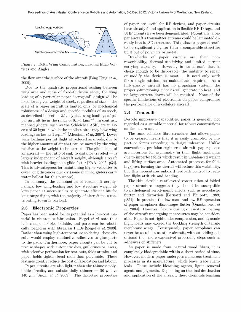
Figure 2: Delta Wing Configuration, Leading Edge Vor-tices and Angles.
the flow over the surface of the aircraft [Bing Feng et al,2009].
Due to the quadratic proportional scaling betweenwing area and mass of fixed-thickness sheet, the wingloading of a particular paper “aerogami” design will befixed for a given weight of stock, regardless of size — thescale of a paper aircraft is limited only by mechanicalrobustness of a design and specific modulus of its stock,as described in section 2.1. Typical wing loadings of pa-per aircraft lie in the range of 0.1–1 kgm−2. In contrast,manned gliders, such as the Schleicher ASK, are in ex-cess of 30 kgm−2, while the smallest birds may have wingloadings as low as 1 kgm−2 [Alerstam et al, 2007]. Lowerwing loadings permit flight at reduced airspeeds, due tothe higher amount of air that can be moved by the wingrelative to the weight to be carried. The glide slope ofan aircraft — the ratio of sink to distance traveled — islargely independent of aircraft weight, although aircraftwith heavier loading must glide faster [FAA, 2005, p34].This is advantageous for maintaining higher velocities tocover long distances quickly (some manned gliders carrywater ballast for this purpose).
In summary, the combination of vortex lift aerody-namics, low wing-loading and low structure weight al-lows paper at micro scales to generate efficient lift forlong range flight, with the majority of aircraft mass con-tributing towards payload.
2.3 Electronic Properties
Paper has been noted for its potential as a low-cost ma-terial in electronics fabrication. Siegel et al note thatit is cheap, flexible, foldable, and parts can be roboti-cally loaded as with fibreglass PCBs [Siegel et al, 2009].Rather than using high-temperature soldering, these cir-cuits would employ conductive adhesives to glue partsto the pads. Furthermore, paper circuits can be cut toprecise shapes with automatic dies, guillotines or lasers,with selective perforation for tear-outs, folds or tabs, andpaper holds tighter bend radii than polyimide. Thesefeatures greatly reduce the cost of fabrication and labour.
Paper circuits are also lighter than the thinnest poly-imide circuits, and substantially thinner — 50 µm vs140 µm [Siegel et al, 2009]. The dielectric properties
of paper are useful for RF devices, and paper circuitshave already found application in flexible RFID tags, andUHF circuits have been demonstrated. Potentially, a pa-per aircraft’s transmitter antenna could be laminated di-rectly into its 3D structure. This allows a paper aircraftto be significantly lighter than a comparable structurebuilt out of polymers or metal.
Drawbacks of paper circuits are their non-reworkability, thermal sensitivity and limited currentcarrying capacity. However, in an aircraft that ischeap enough to be disposable, the inability to repairor modify the device is moot — it need only workfor a single mission, no maintenance required. As afully-passive aircraft has no propulsion system, theproperly-functioning avionics will generate no heat, andno large current draws will be required. None of thespecific limitations of electronics on paper compromisethe performance of a cellulose aircraft.
2.4 Tradeoffs
Despite impressive capabilities, paper is generally notregarded as a suitable material for robust constructionson the macro scale.
The same cellulose fibre structure that allows paperto be creased means that it is easily crumpled by im-pact or forces exceeding its design tolerance. Unlikeconventional precision-engineered aircraft, paper planesare notorious for asymmetry in their flight mechanicsdue to imperfect folds which result in unbalanced weightand lifting surface area. Automated processes for fold-ing/press forming the aircraft will reduce this variability,but this necessitates onboard feedback control to regu-late flight attitude and heading.
The thin, flexible cantilevered construction of foldedpaper structures suggests they should be susceptibleto pathological aerodynamic effects, such as aeroelasticflutter and distortion [Bernard and Philpott, 1989,p351]. In practice, the low mass and low-RE operationof paper aeroplanes discourages flutter [Quackenbush etal, 2004]. However, flexure during quasi-static loadingof the aircraft undergoing manoeuvres may be consider-able. Paper is not rigid under compression, and dynamicflight loads may exceed the buckling strength of tensilemembrane wings. Consequently, paper aeroplanes cannever be as robust as other aircraft, without adding ad-ditional (i.e. more expensive) processing steps such asadhesives or stiffeners.
As paper is made from natural wood fibres, it iscompletely biodegradable within a short period of time.However, modern paper undergoes numerous treatmentprocesses in its manufacture, which leave trace chem-icals. These include bleaching agents, lignin removalagents and pigments. Depending on the final destinationand application of the aircraft, these chemicals leaching
Proceedings of Australasian Conference on Robotics and Automation, 3-5 Dec 2012, Victoria University of Wellington, New Zealand.

into the environment may not be tolerable. Specialisedpapers are available that omit various steps incorporat-ing these chemicals, but this comes at increased cost anddecreased mechanical performance due to the smallerproduction volumes.
Finally, the cellulose fibre matrix is susceptible tomoisture. If an untreated paper aircraft gets wet (asis highly likely for long-range flight), the mechanicalstrength of the vehicle will be compromised. An air-craft intended for circum-global flight must therefore betreated with water-proofing, which may come at the ex-pense of complete biodegradability of the airframe2.
3 Proof of Concept
A proof of concept platform has been developed for per-formance and flight control experiments with paper sub-strate aircraft. The aircraft will be used to develop sys-tems for autonomous gliding flight, and eventual long-distance waypoint navigation. This section presents theweight budget, wing loading and control analysis usedin ascertaining that the complete aircraft will be viable,and reports early passive gliding experiments.
3.1 Aerodynamic Design
The structure chosen for the proof-of-concept aircraft isthe traditional delta shape, folded from A4 stock, com-monly referred to as the ‘classic dart’. The A4 size isspecified by the ISO 216 standard, stipulating dimen-sions of 210±2 mm by 297±2 mm. Office-grade paperstock is approximately 90 gsm, which yields an unladenflying mass of 5.6 g. With a sensor board and bat-tery weighing 4.5 g and two actuators weighing 0.25 geach, the fully-laden aircraft is approximately double theempty weight.
The ISO 216 classic dart will always have a wing areaof approximately 0.025 m2, depending on the size of thevertical stabiliser. For unladen 90 gsm aircraft, this willbe 0.22 kgm−2. When equipped with the sensor andcontrol module, the proof-of-concept MAV has a wingloading of approximately 0.4 kgm−2. The delta wing hasΛ = 67.5. As the aircraft is constructed from a singlesheet of uniform substrate, and there are no span-wisefolds, the centre of gravity (COG) will remain at the mid-point of the fuselage. The diagonal folds at the nose ofthe aircraft put the centre of lift rearwards, close to theaft third-length. This makes the aircraft passively longi-tudinally stable in trimmed pitch [Bernard and Philpott,1989, p294]. Adding the mass of the avionics system andbattery forward of the unladen COG will not adverselyeffect stability, but will reduce flight pitch attitude.
3.2 Avionics
Avionics for the first iteration of the disposable MAVinclude a Microchip 16-series PIC microcontroller, con-
Figure 3: Polyimide Test Article and Circuit (inset).
Figure 4: Cellulose Proof-of-Concept UAV.
nected to an Invensense MPU-6050 inertial measurementunit, and two Plantraco voice-coil actuators (see Fig. 3).Power is provided by a 20 mAh lithium polymer cell,regulated on board to 3.3 V. A battery protection ICprevents accidental over-discharge of the cell.
The voice-coil actuators are controlled with two FETs,allowing single-ended actuation. As the aircraft must flyslightly nose-up to exploit the delta vortex-lift effect, itis not necessary to include a larger H-bridge circuit toallow double-ended activation of the coil; zero duty-cycleapplied to the elevons is homologous to negative input.
Prior to fabricating printed paper circuit boards, aconventionally fabricated circuit was developed to provethe avionics design. This consisted of a half-scale (A5)polyimide circuit board with similar substrate and foilthickness to that expected by the cellulose version. Thetest article is capable of flight in its own right, but hassubstantially higher weight compared with cellulose.
2. Note that while a paper airframe is biodegradable, electronicsgenerally are not. One solution is to encase miniaturised avionics ininert glass, to prevent or slow the leaching of dangerous substances.
Proceedings of Australasian Conference on Robotics and Automation, 3-5 Dec 2012, Victoria University of Wellington, New Zealand.

The test design included a copper ground plane toboth enable the polyimide to hold a bend, and to testthe conductivity of cold-forged flex across the bendingradii anticipated in the fabrication of the paper version.The tests showed that the 0.5 mm bend radii at thewing roots could be tolerated without fracture, but it wasfound that double-layer copper is practically too stiff andheavy — the majority of metal film must be etched awayprior to both reduce weight and difficulty in folding.
For initial testing of the flight control system, thecellulose proof-of-concept system employs the avionicsmodule from the polyimide test article laminated on pa-per (see Fig. 4). It is expected that the ultimate systemconstructed on printed paper circuit boards will incor-porate ICs in caseless chip-scale packages.
3.3 Flight Control
The flight mechanics of a properly-trimmed classic dartare known to be locally stable, with slow unstable cou-pled pitch and roll. In the low-RE flow regime, viscousforces dominate [Potter and Wiggert, 1997] — oscilla-tory modes (such as “Dutch roll” ) are expected to beintrinsically damped. However, spiral instability mode isstrongly exerted due to the slender wings and low verticalstabilizer. The key goal in flight control lies in maintain-ing wing-level attitude and correct α for most efficientcruise performance.
The proof-of-concept system has a 6-axis inertial sen-sor for regulating flight attitude. Control forces are ap-plied by twin elevon aerodynamic surfaces at the out-side trailing edge of the delta wing, where the separatedvortices flow parallel to the leading edge [Bernard andPhilpott, 1989, p25]. The actuating servo tabs double asthe aerodynamic control surfaces, eliminating additionalmanufacturing steps.
While the design of the classic dart incorporates thecentre fuselage as a vertical stabilizer, no rudder has beenincluded. This is to save on weight and avoid adding ad-ditional masses at the rear which would move the COGaft. The coupled banking-turning mechanics of aero-planes, the low mass of the vehicle, and the small size ofthe aircraft obviates the need for full actuation. How-ever, coupled flight modes of fixed-wing aircraft compli-cate the control design, as perfectly coordinated flightmakes off-vertical gravity vector components unobserv-able by accelerometers, increasing reliance of potentiallybiased gyroscopes.
3.4 Glide Performance
The proof-of-concept aircraft consists of polyimide PCBlaminated to standard A4 office paper stock, folded ac-cording to the pattern given in the appendix, with elevoncontrol surfaces mounted at the wing-tip trailing edges.It was expected that the added mass of the polyimide
Figure 5: Example Glide Test Experiment Montage.
board would be minimal, and not have a great impacton performance. This assertion was tested by compar-ing the gliding range of a paper aircraft without avionics,with that of the same aircraft with avionics added.
A catapult fitted with elastic with was used to launchthe UAV. The catapult was drawn back to a fixed dis-tance to ensure that each launch delivered consistent, re-peatable energy. The aircraft were launched horizontallyfrom 1440 mm above the ground, using passive stabilityof the aircraft (without feedback) and the distance towhere they first contacted the ground was recorded (seeFig. 5). The experiment was repeated 20 times for theunladen configuration and 20 times for the laden config-urations. For consistency, the same aircraft was used forall tests from both sets of tests.
As the energy stored in the elastic catapult is equalacross all tests, but the laden aircraft weighs 10.6 g com-pared to the unladen weight of 5.6 g, the velocity reachedby the lighter aircraft will be approximately 1.37 timesthat of the heavier aircraft. However, as the heavierglider must fly faster to sustain lift, a higher sink rateand shorter distance is anticipated.
To account for this, consider the Newtonian and aero-dynamic force equations. For time of flight t, it is knownthat the horizontal distance traveled x will be:
x = t · Vx (10)
where Vx is the horizontal launch velocity. In glidingflight the aircraft will accelerate downward at a rate pro-portional with mass to gravity minus the lift force:
mVz = mg − c1ρclV 2x (11)
It is known that for descent under constant acceleration,distance fallen in time t is:
1
2Vzt
2 = z (12)
Proceedings of Australasian Conference on Robotics and Automation, 3-5 Dec 2012, Victoria University of Wellington, New Zealand.
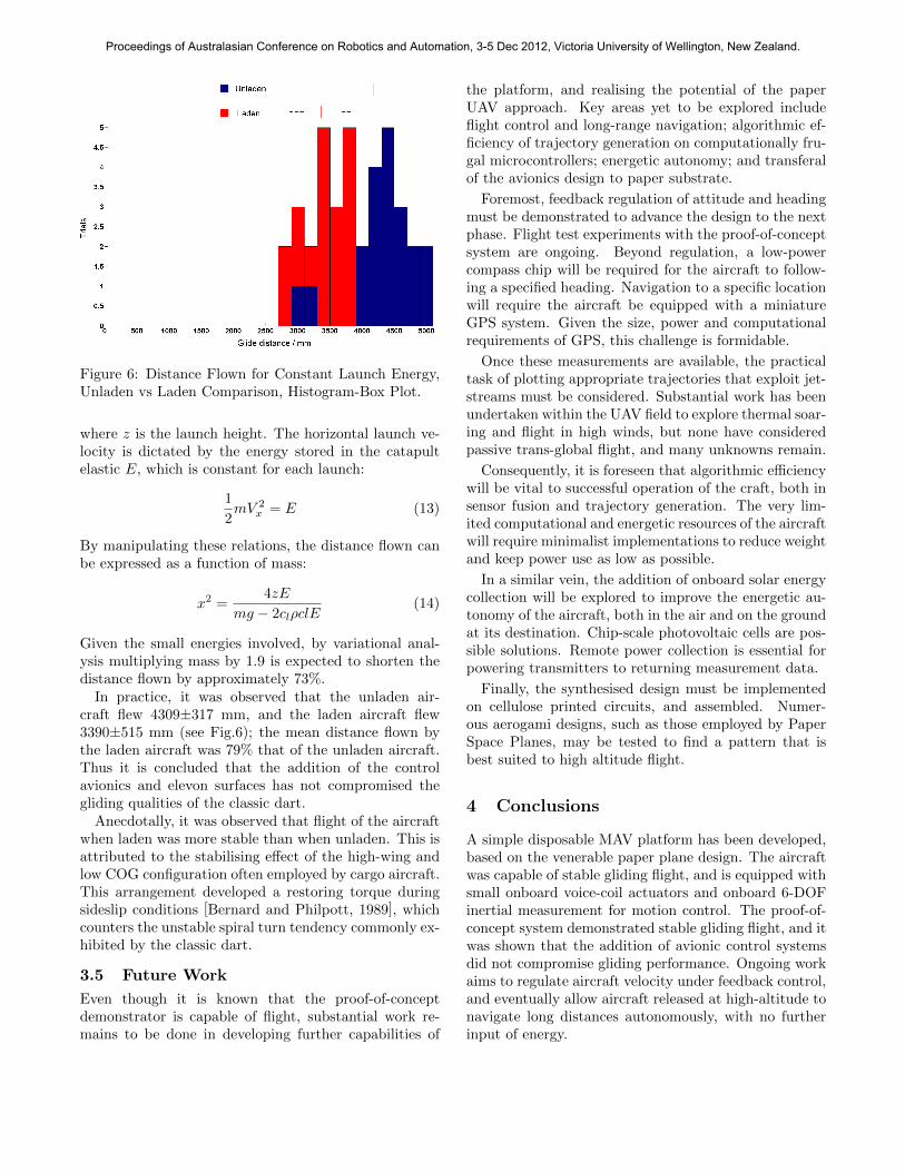
Figure 6: Distance Flown for Constant Launch Energy,Unladen vs Laden Comparison, Histogram-Box Plot.
where z is the launch height. The horizontal launch ve-locity is dictated by the energy stored in the catapultelastic E, which is constant for each launch:
1
2mV 2
x = E (13)
By manipulating these relations, the distance flown canbe expressed as a function of mass:
x2 =4zE
mg − 2clρclE(14)
Given the small energies involved, by variational anal-ysis multiplying mass by 1.9 is expected to shorten thedistance flown by approximately 73%.
In practice, it was observed that the unladen air-craft flew 4309±317 mm, and the laden aircraft flew3390±515 mm (see Fig.6); the mean distance flown bythe laden aircraft was 79% that of the unladen aircraft.Thus it is concluded that the addition of the controlavionics and elevon surfaces has not compromised thegliding qualities of the classic dart.
Anecdotally, it was observed that flight of the aircraftwhen laden was more stable than when unladen. This isattributed to the stabilising effect of the high-wing andlow COG configuration often employed by cargo aircraft.This arrangement developed a restoring torque duringsideslip conditions [Bernard and Philpott, 1989], whichcounters the unstable spiral turn tendency commonly ex-hibited by the classic dart.
3.5 Future Work
Even though it is known that the proof-of-conceptdemonstrator is capable of flight, substantial work re-mains to be done in developing further capabilities of
the platform, and realising the potential of the paperUAV approach. Key areas yet to be explored includeflight control and long-range navigation; algorithmic ef-ficiency of trajectory generation on computationally fru-gal microcontrollers; energetic autonomy; and transferalof the avionics design to paper substrate.
Foremost, feedback regulation of attitude and headingmust be demonstrated to advance the design to the nextphase. Flight test experiments with the proof-of-conceptsystem are ongoing. Beyond regulation, a low-powercompass chip will be required for the aircraft to follow-ing a specified heading. Navigation to a specific locationwill require the aircraft be equipped with a miniatureGPS system. Given the size, power and computationalrequirements of GPS, this challenge is formidable.
Once these measurements are available, the practicaltask of plotting appropriate trajectories that exploit jet-streams must be considered. Substantial work has beenundertaken within the UAV field to explore thermal soar-ing and flight in high winds, but none have consideredpassive trans-global flight, and many unknowns remain.
Consequently, it is foreseen that algorithmic efficiencywill be vital to successful operation of the craft, both insensor fusion and trajectory generation. The very lim-ited computational and energetic resources of the aircraftwill require minimalist implementations to reduce weightand keep power use as low as possible.
In a similar vein, the addition of onboard solar energycollection will be explored to improve the energetic au-tonomy of the aircraft, both in the air and on the groundat its destination. Chip-scale photovoltaic cells are pos-sible solutions. Remote power collection is essential forpowering transmitters to returning measurement data.
Finally, the synthesised design must be implementedon cellulose printed circuits, and assembled. Numer-ous aerogami designs, such as those employed by PaperSpace Planes, may be tested to find a pattern that isbest suited to high altitude flight.
4 Conclusions
A simple disposable MAV platform has been developed,based on the venerable paper plane design. The aircraftwas capable of stable gliding flight, and is equipped withsmall onboard voice-coil actuators and onboard 6-DOFinertial measurement for motion control. The proof-of-concept system demonstrated stable gliding flight, and itwas shown that the addition of avionic control systemsdid not compromise gliding performance. Ongoing workaims to regulate aircraft velocity under feedback control,and eventually allow aircraft released at high-altitude tonavigate long distances autonomously, with no furtherinput of energy.
Proceedings of Australasian Conference on Robotics and Automation, 3-5 Dec 2012, Victoria University of Wellington, New Zealand.

5 Acknowledgements
The author would like to thank Surya Singh for his as-sistance with this paper.
6 Appendix: Classic Dart Instructions
See next page.
References
[Perez et al, 2011] N. Perez-Arancibia, K. Ma, K. Gal-loway, J. Greenberg, and R. Wood, ”First ControlledVertical Flight of a Biologically Inspired Microrobot,”Bioinspiration & Biomimetics, Vol. 6, 036009, 2011.
[Hoover et al, 2010] A. Hoover, S. Burden, X-Y. Fu,S. Sastry, and R. Fearing, “Bio-inspired design anddynamic maneuverability of a minimally actuated six-legged robot,” In Proc. IEEE BioRob, 2010.
[Polzinger et al, 2011] B. Polzinger, F. Schoen,V. Matic, J. Keck, H. Willeck, W. Eberhardtand H. Kueck, “UV-sintering of inkjet-printed con-ductive silver track,” In proc. IEEE Nanotechnology,2011.
[Mei et al, 2005] J. Mei, M. Lovell and M. Mickle, “For-mulation and processing of novel conductive solutioninks in continuous inkjet printing of 3-D electric cir-cuits,” IEEE Trans. Electronics Packaging Manufac-turing, Vol. 28 , No. 3, pp265–273, 2005.
[Allen et al, 2011] M. Allen, A. Alastalo, M. Suhonen,T. Mattila, J. Leppaniemi, H. Seppa, “ContactlessElectrical Sintering of Silver Nanoparticles on Flex-ible Substrates,” IEEE Trans. Microwave Theory andTechniques, Vol.59 , No.5, pp1419–1429, 2011.
[Siegel et al, 2009] A. Siegel, S. Phillips, M. Dickey,N. Lu, Z. Suo and G. Whitesides, ”Foldable PrintedCircuit Boards on Paper Substrates,” Advanced Func-tional Materials, Vol. 20, pp28-35, 2009.
[Paper Space Planes, 2011] Project Space Planes,“Flight Log,” http://projectspaceplanes.com/,(2011).
[Funuyo, 2008] I. Fuyuno, “The Ultimate Pa-per Airplane,” http://www.airspacemag.com/
space-exploration/The_Ultimate_Paper_
Airplane.html, (2008).
[CUMG, 2012] Cambridge University Materi-als Group, “Interactive Materials Charts,”http://www-materials.eng.cam.ac.uk/mpsite/
interactive_charts/, (2012).
[Traub et al, 1998] L. Traub, B. Moeller andO. Rediniotis,“Low-Reynolds-number effects ondelta-wing aerodynamics,” Journal of Aircraft,Vol. 35, No. 4, pp653–656, 1998.
[Mueller, 2007] T. Mueller, Introduction to the Designof Fixed-Wing Micro Air Vehicles, American Instituteof Aeronautics and Astronautics, 2007.
[Bing Feng et al, 2009] N. Bing Feng, K. Qiao Mei andP. Yin Yin, “On the Aerodynamics of Paper Air-planes,” In proc. 27th AIAA Applied AerodynamicsConference, 2009.
[Phipps et al, 2002] C. Phipps, M. Yamaguchi, R. Nak-agawa, K. Aoki, H. Mine, Y.Ogata, C. Baasandash,M. Nakagawa, K. Fujiwara, K. Yoshida, A. Nishiguchiand I. Kajiwara, “Microairplane propelled by laserdriven exotic target,” Applied Physics Letters, Vol. 80,No. 23, pp4318–4320, 2002.
[Pounds and Mahony, 2005] P. Pounds and R. Mahony,“Small-Scale Aeroelastic Rotor Simulation, Designand Fabrication,” In proc. Australasian Conference onRobotics and Automation, 2005.
[Bernard and Philpott, 1989] R. Bernard andD. Philpott, Aircraft Flight, 3rd Ed., PearsonEducation Ltd., Edinburgh Gate, Harlow, Essex,England, 1989.
[Katz and Plotkin, 2001] J. Katz and A. Plotkin, Low-Speed Aerodynamics, 2nd Ed., Cambridge UniversityPress, New York, New York, USA, 2001.
[Polhamus, 1966] E. Polhamus, “A Concept of the Vor-tex Lift of Sharp-Edge Delta Wings Based on aLeading-Edge-Suction Analogy,” National Aeronau-tics nad Space Administration, 1966.
[Traub, 2000] L. Traub, “Implications of the Insensi-tivity of Vortex Lift to Sweep,” Journal of Aircraft,Vol. 37, No. 3, pp531–533, 2000.
[Greenwell, 2010] D. Greenwell, “Gurney Flaps on Slen-der and Nonslender Delta Wings,” Journal of Aircraft,Vol. 47, No. 2, pp675–681, 2010.
[Alerstam et al, 2007] T. Alerstam, M. Rosen,J. Backman, P. Ericson and O. Hellgren, “FlightSpeeds among Bird Species: Allometric and Phyloge-netic Effects,” PLoS Biology 5(8): e197, 2007.
[FAA, 2005] Federal Aviation Authority, “FAA-H-8083-13 Glider Flying Handbook,” http://www.faa.gov/
library/manuals/aircraft/glider_handbook/
(2005).
[Quackenbush et al, 2004] T. Quackenbush, D. Wachs-press, A. Boschitschand C. Solomon, “Aeromechanical Analysis Tools forDesign and Simulation of VTOL UAV Systems,”urlhttp://www.continuum-dynamics.com/documents/MSA001.pdf (2004).
[Potter and Wiggert, 1997] M. Potter and D. Wiggert,Mechanics of Fluids, Prentice-Hall, Upper SaddleRiver, New Jersey, USA, 1997.
Proceedings of Australasian Conference on Robotics and Automation, 3-5 Dec 2012, Victoria University of Wellington, New Zealand.

1
2
3
3. Fold two halves together
2. Fold top corners in
1. Fold top corners in
4. Fold each wing out
Affix avionics module here
5. Launch!
2
4
1
4
Affix elevon here Affix elevon here
Proceedings of Australasian Conference on Robotics and Automation, 3-5 Dec 2012, Victoria University of Wellington, New Zealand.