paper3 - the 5th iros workshop on planning, perception and
TRANSCRIPT

Collaborative Monocular SLAM with Multiple Micro Aerial Vehicles
Christian Forster1, Simon Lynen2, Laurent Kneip2, Davide Scaramuzza1
Abstract— This paper presents a framework for collaborativelocalization and mapping with multiple Micro Aerial Vehicles(MAVs) in unknown environments. Each MAV estimates itsmotion individually using an onboard, monocular visual odom-etry algorithm. The system of MAVs acts as a distributedpreprocessor that streams only features of selected keyframesand relative-pose estimates to a centralized ground station.The ground station creates an individual map for each MAVand merges them together whenever it detects overlaps. Thisallows the MAVs to express their position in a common, globalcoordinate frame. The key to real-time performance is thedesign of data-structures and processes that allow multiplethreads to concurrently read and modify the same map. Thepresented framework is tested in both indoor and outdoorenvironments with up to three MAVs. To the best of ourknowledge, this is the first work on real-time collaborativemonocular SLAM, which has also been applied to MAVs.
I. INTRODUCTION
A. Motivation
Micro aerial vehicles will soon play a major role in
missions, such as security surveillance, search and rescue,
and environment inspection. However, for such operations,
navigating based on GPS information only is not sufficient.
Fully autonomous operation in urban environments and in-
door spaces requires micro helicopters to rely on alternative
localization systems. However, weight restriction and battery
autonomy impose great limitations on the choice of the
sensors. For small-sized and lightweight platforms (less than
40cm and less than 1kg), laser scanners are still too heavy
and consume too much power. Therefore, the only viable
solution is to use a combination of onboard cameras and
IMU (Inertial Measurement Unit). Successful demonstrations
of a MAV performing autonomous basic maneuvers, using
only a single onboard camera, IMU, and an onboard Atom
computer, have been done in our previous work [1], [2]. In
this paper, we attempt to go one step forward, and address
the problem of collaborative localization and mapping with
multiple MAVs in unknown environments.
The application to multiple agents allows the use of
redundant and parallel mechanisms to achieve increased ro-
bustness and efficiency. Several tasks—such as the workload
of mapping an environment—can be shared among all the
agents. As a practical result, the shared map among the
1C. Forster and D. Scaramuzza are with the Artificial Intelligence Lab—Robotics and Perception Group, University of Zurich, Switzerland—http:
//rpg.ifi.uzh.ch.2S. Lynen and L. Kneip are with the Autonomous Systems Lab, ETH
Zurich, Switzerland.This research was supported by the Swiss National Science Foundation
through project number 200021-143607 (”Swarm of Flying Cameras”) andthe National Centre of Competence in Research Robotics.
robots allows the computation of the relative configuration
of the agents, which forms a basis for multi-robot path
planning and cooperative behaviors. Despite these advan-
tages, solving the Simultaneous-Localization-And-Mapping
(SLAM) problem with multiple robots generally increases the
computational and inter-robot communication load.
B. Related Work
Most works in multi-robot SLAM have been done using
range sensors (e.g., laser, sonars, and stereovision) and/or
ground mobile robots moving in the same 2D plane [3]–[6].
Very little work has been done using bearing-only sensors
(monocular vision) and for unconstrained (6DoF) motion
of the agents (e.g., wearable sensors, hand-held cameras,
and flying robots). This problem—known as multi-camera
structure from motion or multi-camera SLAM—can be ap-
proached differently depending on whether the cameras (i.e.,
the robots) can “see” each other or not. If the former case,
their relative configuration can be inferred from the relative
bearing-angle observations [7], [8]. In the latter case, this
can be done starting from the common scene observed by
the cameras. The work described in this paper belongs to the
second category.
In [9], the authors use a single extended Kalman filter
SLAM algorithm with an extended state vector composed of
each camera pose and the observed features. Specifying the
relative configuration at startup, they demonstrate results on
two cameras attached to two bicycles. In [10], the authors
describe a system for cooperative mapping using both aerial
and ground robots equipped with stereo cameras. Each robot
creates local submaps using an extended Kalman filter and
maintains a global graph of submap positions. Rendezvous
between robots, feature correspondences, and absolute GPS
localization measurements, trigger loop closures which re-
sults in exchange of submap positions among the robots.
In [11], the authors study the case of two MAVs which,
equipped with monocular cameras and IMU, form a flexible
stereo rig. Using feature correspondence in the overlapping
field of view, the relative pose of the two robots can be
estimated. In [12], the authors process the video streams from
multiple hand-held cameras. The process is synchronized in
that the images from all the cameras are processed all at once
at each time step. This makes their system impractical for
robotic applications, where the input of each camera should
be computed asynchronously in order to cope with missing
data and delays. Additionally, it is assumed that all cameras
observe the same scene at start. In [13], a system was
presented, where a single robot has to continuously localize
within maps created during previous mapping sessions by
the same robot. Although this work was not applied to
multiple robots, it can, however, be seen as an instance of a
multi-robot mapping process where each map was created in
previous sessions by the same robot. Finally, in [14], a fully
decentralized SLAM system is presented where each robot
maintains a consistent augmented local map that combines
local and neighbourhood information. The system has been
validated in simulation.
C. Contributions and Outline
In the endeavor of enabling multi-robot navigation of
MAVs with very-low onboard computing power, our goal is
to employ the MAV onboard computer for low-level tasks—
such as feature extraction, relative-motion estimation, and
flight control—and delegate a ground station to higher-level
tasks—such as mapping, loop-closure detection and map
merging. The decoupling of motion estimation and mapping
is useful in real-world scenarios, where the robots have to
maintain some degree of autonomy in case of intermittent
communication with the ground station.
An overview of the proposed approach is depicted in
Figure 1. Each MAV estimates its motion individually by
running an onboard visual odometry (VO) algorithm that is
used to both track the robot motion and stabilize its 6DoF
pose during flight. The outputs of the VO—i.e. keyframe
features and relative-pose estimates between keyframes—are
streamed to a central ground station where our Collabora-
tive Structure from Motion (CSfM) system is running. The
CSfM system on the ground station creates an individual
map for each MAV and merges them together whenever
it detects overlaps. The ground station processes the data
asynchronously, as they arrive, which accounts for situations
where the robots do not start all at the same time or where
some data are missing due to a communication failure. To
achieve real-time performance, we design data-structures and
processes that allow multiple threads (one for each MAV) to
concurrently read and modify the same map. Additionally,
we devise a solution to tackle the scale-difference between
the onboard-estimated trajectories and those estimated on the
ground station.
The remainder of the paper is structured as follows. Sec-
tion II provides an overview of the CSfM system. Section III
details the general mapping pipeline. Section IV explains
how overlaps between maps are detected and how they are
merged into a single global map. Section V describes the
implementation design for concurrent map access. Finally,
Section VI provides the experimental results.
II. SYSTEM OVERVIEW
Each MAV tracks its own position using a keyframe-
based onboard monocular VO algorithm. We chose to employ
the VO presented in our previous work [15]. It is boosted
in terms of robustness and efficiency through the use of
the relative-rotation prior from the onboard IMU. However,
our proposed CSfM system is modular and, therefore, any
alternative keyframe-based VO algorithm (such as [16])
could be used.
VO 1
PlaceRecognizer
CSfM
Frame
Handler
Thread 2
Frame
Handler
Thread 1
Map
VO 2Key-Frame Message:
Key-frame features
Relative position toprevious key-frame
Overlap
Detector
Overlap
Detector
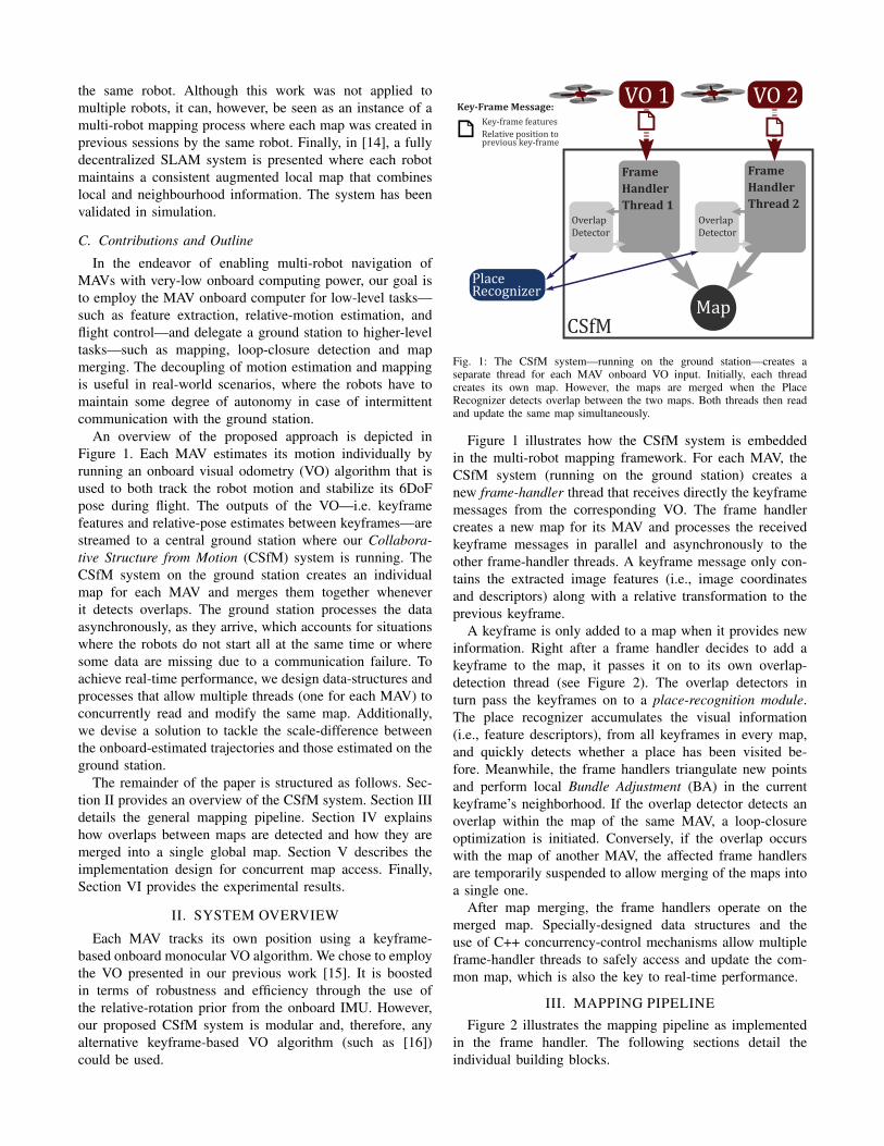
Fig. 1: The CSfM system—running on the ground station—creates aseparate thread for each MAV onboard VO input. Initially, each threadcreates its own map. However, the maps are merged when the PlaceRecognizer detects overlap between the two maps. Both threads then readand update the same map simultaneously.
Figure 1 illustrates how the CSfM system is embedded
in the multi-robot mapping framework. For each MAV, the
CSfM system (running on the ground station) creates a
new frame-handler thread that receives directly the keyframe
messages from the corresponding VO. The frame handler
creates a new map for its MAV and processes the received
keyframe messages in parallel and asynchronously to the
other frame-handler threads. A keyframe message only con-
tains the extracted image features (i.e., image coordinates
and descriptors) along with a relative transformation to the
previous keyframe.
A keyframe is only added to a map when it provides new
information. Right after a frame handler decides to add a
keyframe to the map, it passes it on to its own overlap-
detection thread (see Figure 2). The overlap detectors in
turn pass the keyframes on to a place-recognition module.
The place recognizer accumulates the visual information
(i.e., feature descriptors), from all keyframes in every map,
and quickly detects whether a place has been visited be-
fore. Meanwhile, the frame handlers triangulate new points
and perform local Bundle Adjustment (BA) in the current
keyframe’s neighborhood. If the overlap detector detects an
overlap within the map of the same MAV, a loop-closure
optimization is initiated. Conversely, if the overlap occurs
with the map of another MAV, the affected frame handlers
are temporarily suspended to allow merging of the maps into
a single one.
After map merging, the frame handlers operate on the
merged map. Specially-designed data structures and the
use of C++ concurrency-control mechanisms allow multiple
frame-handler threads to safely access and update the com-
mon map, which is also the key to real-time performance.
III. MAPPING PIPELINE
Figure 2 illustrates the mapping pipeline as implemented
in the frame handler. The following sections detail the
individual building blocks.

Visual Odometry
Pla
ceR
eco
gn
ize
r
Overlap Detector
Frame
Handler
CSfM
Read Frame
Map Reprojection
Triangulation
Local BA
Save Keyframe
Loop Closure/Map Merging
Scale DifferenceEstimation
Core & PeripherySelection
Pose Optimization
is Keyframe?
Yes
No
Yes
NoMapOverlap?
Call PlaceRecognizer
Geometric�����������
Fig. 2: Mapping pipeline executed inside the frame-handling threads of theCSfM system.
A. Keyframe Message
Each MAV tracks its own position (with respect to its
own starting point) using a keyframe-based onboard monoc-
ular VO algorithm. When the onboard VO selects a new
keyframe, a message to the ground station is sent containing
the extracted features along with the relative transformation
(Rk−1,k, tk−1,k) to the previous keyframe.
B. Handling the Keyframe Message by the Ground Station
When the ground station receives a keyframe message
from a MAV, there are two possibilities: (i) if this is the first
message from that MAV, then the CSfM system (running
on the ground station) creates a new frame-handler thread
and triangulates the received features into map-points as
soon as the next message arrives; (ii) if a frame-handler
for that MAV already exists, correspondences between the
existing 3D map-points and the features in the new keyframe
are identified. Additionally, the frame-handler updates the
absolute pose (tk,Rk) of the new keyframe in the map:
tk = tk−1 +Rk−1 tk−1,k
Rk = Rk−1 Rk−1,k .(1)
C. Pose Optimization
The CSfM system optimizes the absolute 6DoF pose of the
new keyframe within the map by minimizing the reprojection
error of all map-points visible by that keyframe using a
nonlinear least-squares solver [17].1
1The reprojection error is the Euclidean distance e between the repro-jected point and the corresponding observed feature in the image plane.
MAV
Groundstation
CSFM
R, t
R, t
Fig. 3: The VO on the MAV maintains a map with a limited number ofkeyframes (e.g., 5) for processing-speed reasons. Therefore, the scale of theonboard VO drifts faster than on the ground-station. The relative translationt computed by the MAV’s onboard VO needs to be corrected with the scalefactor λ for the CSfM map.
D. Scale-Difference Estimation between VO and CSfM
Each MAV’s onboard monocular VO produces motion and
structure information only up to an unknown scale factor.
Furthermore, this scale factor is not constant, but drifts over
time. On the ground-station side, the CSfM system also
exhibits a scale drift as long as no loop closures occur.
These two scale factors are not equal and diverge at different
rates (see Figure 3). If the scale difference is not corrected,
scale jumps can occur as it is depicted in Figure 6 (refer to
Section VI). A scale jump occurs if the MAV’s VO’s scale
drifts too much with respect to the CSfM map such that in
the reprojection step no correspondences can be found and
thus the pose cannot be optimized anymore towards the right
position.
To correct this scale difference, we compare the estimated
relative translation t before and after the pose optimization
step:
λk =||tk−1,k after Optimization||
||tk−1,k before Optimization||. (2)
Hence, we compute the new scale factor λk with the follow-
ing update rule:
λk = λk−1 + κ · (λk − λk−1), (3)
where κ represents the smoothing factor. Empirically, we
found that κ = 0.05 is a good choice.
Using the estimated scale-difference factor λk, the relative
position received from the MAV’s onboard VO is corrected
by the corresponding frame-handler before a new keyframe is
used. The position computed by Equation (1) is then updated
to:
tk = tk−1 + λkRk−1 tk−1,k. (4)
This step further justifies why the pose of keyframes that
are later not inserted in the map must also be optimized. It
allows us to successfully track the robot’s pose with respect
to the map and to estimate the scale difference.
E. Keyframe Selection
While the use of more map-points improves the accuracy
of the map, increasing the number of keyframes has only
minor effects once robustness is achieved [18]. Therefore,
similar to [16], new keyframes are only inserted in the map
if the distance to the closest keyframe is large enough.2
Depending on the trajectory, the CSfM system rejects on
average up to 85% of the received keyframes, which saves
processing time.
F. Selection of Core and Periphery Keyframes
The CSfM system follows the fundamental concept that no
temporal ordering of keyframes is retained. Keyframe neigh-
bourhoods for optimization and triangulation are selected
based only on spatial adjacency. This means that also older
keyframes—regardless of the MAV they originate from—are
taken into account for these operations, leading to a reduction
of redundant information inside the map. A set C of four
core keyframes is selected, which shares the largest number
of common map-point observations with the new keyframe.
The set of periphery keyframes P is defined by all keyframes
that share at least one common map-point observation with
C or with the new keyframe but which are not in the set C.
G. Triangulation
New map-points are triangulated when a new keyframe
is selected to be inserted in the map. For every unmatched
feature in the new keyframe, we search matching features
along the epipolar lines in the core keyframes. If a matching
descriptor is found, the point is triangulated and projected
into the remaining core and periphery keyframes to increase
the number of measurements. The creation of duplicate
points is inhibited by merging points in case a feature is
already associated with an existing map-point. The merging
step is essential for obtaining sparse and well constrained
maps.
H. Local Bundle Adjustment
Mouragnon et al. [19] have shown the feasibility of
creating an accurate 3D reconstruction in real-time using
incremental bundle adjustment. Therefore, the CSfM system
optimizes the set of core keyframes C together with the
new keyframe and along with the commonly observed map-
points using the g2o framwork [17]. The set of periphery
keyframes P is added to the optimization window with a
fixed pose. The periphery keyframes are required to fix the
scale of the structure and to ensure that the optimization is
optimal with respect to the boundary.
IV. MAP OVERLAP DETECTION AND
PROCESSING
A fundamental characteristic of the CSfM system is its
ability to detect if a MAV reenters an environment that
has already been visited, either by itself or by another
MAV which results in a loop-closure optimization or a
2We set the threshold to 15% of the average scene depth.
map merging respectively. Such overlaps are detected based
on the keyframe appearance (i.e., feature descriptors) and
subsequently geometrically verified.
A. Appearance-based Overlap Detection
If a keyframe is accepted for inclusion in the map, a
second overlap-detection thread is started, which calls the
place-recognizer module (see Figure 2). The external place
recognition module is the same for all frame handlers and
relies on a bag-of-words [20] approach. The exact type
of place recognizer in use depends on the employed local
invariant point descriptor. We initally tested OpenSURF fea-
tures [21], which allow the use of the OpenFABMAP place
recognizer [22]. However, for increased speed, we decided to
use BRISK features [23]. Since binary features have special
clustering properties, a dedicated place-recognition module
was implemented.3
B. Geometric Verification
Each time the place recognizer returns an overlap-
keyframe with similar appearance as the current keyframe,
the overlap detector geometrically verifies the result by ap-
plying the Perspective-Three-Point (P3P) algorithm from our
previous work [24]. The P3P algorithm derives the camera
pose from at least three 3D-to-2D feature correspondences.
These correspondences are established by identifying match-
ing descriptors between map-points—which the overlap-
keyframe observes—and features in the current keyframe. To
remove outliers, we integrated the P3P into a RANSAC [25]
procedure. The output of RANSAC is then the rigid body
transformation between the two keyframes.
C. Map merging
If the detected overlap occurred between two different
maps, the similarity transformation {R, t, s} returned by the
geometric verification step is used to merge the two maps
into one. The factor s accounts for the different scale between
the two maps and can be found by comparing the relative dis-
tances between any combination of 3D map-points which are
common between the two maps. All frame handlers working
on either of the two maps are temporarily suspended, and
the entire candidate map for which an overlap was detected
is subjected to the determined similarity transformation. To
improve the measurements of points and avoid redundant
information in the map, all map-points from each overlapping
map region are reprojected into the keyframes from the
other map and corresponding map-points are merged. A last
important detail consists of applying the scale factor s to
the scale difference factor (see Section III-D) of all frame
handlers that were operating on the transformed map. This
is necessary to ensure that the received relative position
estimates from the VO are correctly scaled with respect to
the map. The frame-handler threads are finally resumed, and
now operate in parallel on the same map. At this stage, it is
3The BRISK-based place-recognizer goes beyond the scope of this paperand, therefore, it is not described here.
important to design the algorithm and data structures such
that concurrent data access is possible (see Section V).
Note that the CSfM node creates references between two
maps only when a loop closure is detected. However, in
practice, the two maps may still contain overlaps in other
regions if the place-recognition or the geometric-verification
steps failed to detect them earlier. However, the CSfM system
is still able to detect and incorporate them in a later stage in
case a MAV retraverses the same environment.
D. Loop closure
The computed similarity transformation parameters
{R, t, s} also incorporate the amount of drift that has been
accumulated along the loop.
The standard solution to optimize both the full map and
keyframes after loop closure is to run global BA. However,
this approach is computationally demanding and may fail
completely due to convergence into local minima. There-
fore, we chose to split the optimization into two steps.
In the first step, we marginalize out the map-points. This
reduces the map representation to a pose-graph with edges
of different strength between poses. Strasdat et al. [26]
were the first to propose 7-DoF pose-graph optimization
including the scale as a drift parameter, which leads to a
substantial improvement in a monocular-SLAM context. The
parametrization of this pose-graph relaxation is included in
the g2o framework [17] and used by the CSfM system.
After pose-graph optimization, the map-points are updated
accordingly and global BA is run to further refine both map-
points and keyframe poses simultaneously.
V. IMPLEMENTATION DESIGN FOR
CONCURRENT MAP ACCESS
If two or more maps have been merged, multiple frame-
handling threads concurrently read and modify a single map
(as depicted in Figure 1). Processing keyframes in parallel
on a multi-core processor is the key to real-time performance
of the CSfM system. However, when multiple things happen
at the same time, special measures need to be taken both on
the data-structure and on the algorithm layout level.
The difficulty of shared memory between multiple threads
comes from the consequences of modifying data. We can
ensure the integrity of the shared data by using the concept of
mutual exclusion locks. This concept defines that if a thread
wants to access some data-object, it first needs to acquire the
data-object’s lock, which is only possible if no other thread
has previously acquired the lock without releasing it.
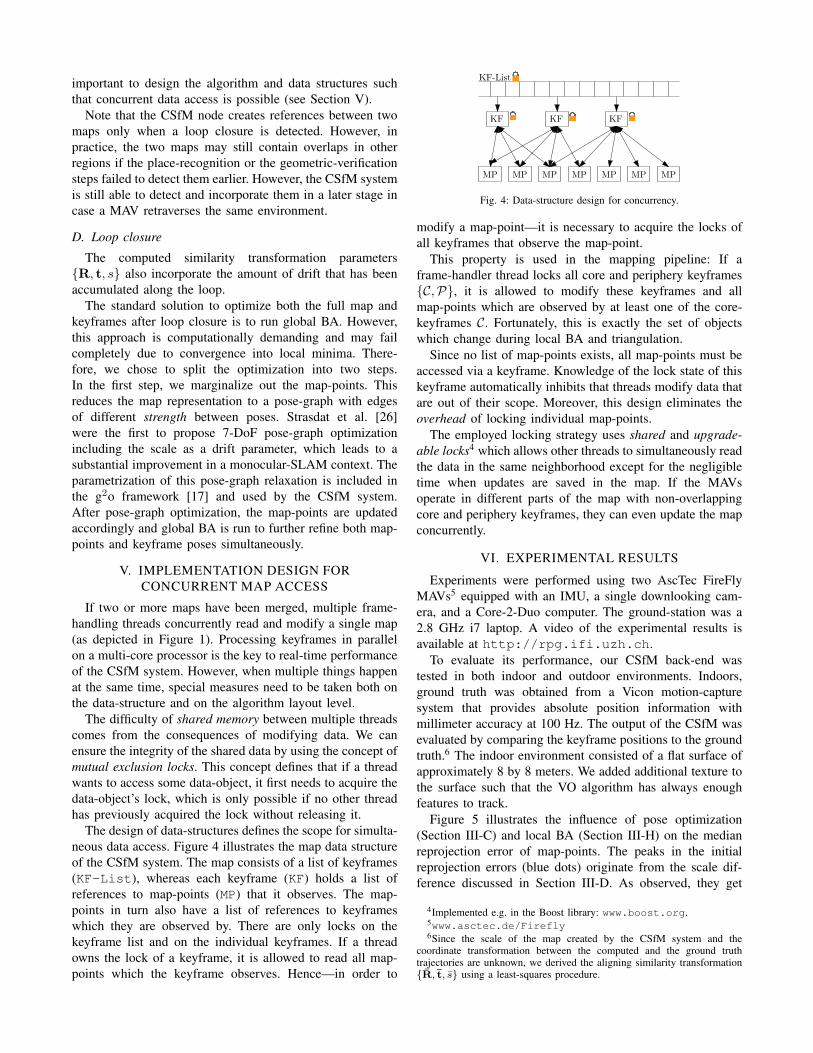
The design of data-structures defines the scope for simulta-
neous data access. Figure 4 illustrates the map data structure
of the CSfM system. The map consists of a list of keyframes
(KF-List), whereas each keyframe (KF) holds a list of
references to map-points (MP) that it observes. The map-
points in turn also have a list of references to keyframes
which they are observed by. There are only locks on the
keyframe list and on the individual keyframes. If a thread
owns the lock of a keyframe, it is allowed to read all map-
points which the keyframe observes. Hence—in order to
KF-List
KF KF KF
MPMP MP MP MP MP MP
Fig. 4: Data-structure design for concurrency.
modify a map-point—it is necessary to acquire the locks of
all keyframes that observe the map-point.
This property is used in the mapping pipeline: If a
frame-handler thread locks all core and periphery keyframes
{C,P}, it is allowed to modify these keyframes and all
map-points which are observed by at least one of the core-
keyframes C. Fortunately, this is exactly the set of objects
which change during local BA and triangulation.
Since no list of map-points exists, all map-points must be
accessed via a keyframe. Knowledge of the lock state of this
keyframe automatically inhibits that threads modify data that
are out of their scope. Moreover, this design eliminates the
overhead of locking individual map-points.
The employed locking strategy uses shared and upgrade-
able locks4 which allows other threads to simultaneously read
the data in the same neighborhood except for the negligible
time when updates are saved in the map. If the MAVs
operate in different parts of the map with non-overlapping
core and periphery keyframes, they can even update the map
concurrently.
VI. EXPERIMENTAL RESULTS
Experiments were performed using two AscTec FireFly
MAVs5 equipped with an IMU, a single downlooking cam-
era, and a Core-2-Duo computer. The ground-station was a
2.8 GHz i7 laptop. A video of the experimental results is
available at http://rpg.ifi.uzh.ch.
To evaluate its performance, our CSfM back-end was
tested in both indoor and outdoor environments. Indoors,
ground truth was obtained from a Vicon motion-capture
system that provides absolute position information with
millimeter accuracy at 100 Hz. The output of the CSfM was
evaluated by comparing the keyframe positions to the ground
truth.6 The indoor environment consisted of a flat surface of
approximately 8 by 8 meters. We added additional texture to
the surface such that the VO algorithm has always enough
features to track.
Figure 5 illustrates the influence of pose optimization
(Section III-C) and local BA (Section III-H) on the median
reprojection error of map-points. The peaks in the initial
reprojection errors (blue dots) originate from the scale dif-
ference discussed in Section III-D. As observed, they get
4Implemented e.g. in the Boost library: www.boost.org.5www.asctec.de/Firefly6Since the scale of the map created by the CSfM system and the
coordinate transformation between the computed and the ground truthtrajectories are unknown, we derived the aligning similarity transformation{R, t, s} using a least-squares procedure.


keyframe rate) compared to streaming entire raw images
(∼86.6 Mbit/s for grayscale 752×480-pixel images and 30
Hz framerate). Note that the reduced keyframe-rate for our
approach is because our VO already preselects a subset of
frames as keyframes.
While the VO onboard the MAV can run at up to 70Hz,
the average keyframe processing time on the ground-station
ranged between 22ms and 45ms, resulting in a frame rate of
up to 45Hz for one MAV. The average computation time per
keyframe depends, to a large extend, on both the trajectory
and the environment. A MAV that is constantly exploring
new environments produces more keyframes—and, thus, a
higher workload for the CSfM system—than a MAV that
remains in previously-mapped areas. In the latter situation,
most keyframes are dropped since they do not provide new
information. On average the CSfM system selects only 85%
of all received keyframes. Regarding the environment, an
increased density of features implicitly leads to an increased
number of map-point references and, thus, higher reprojec-
tion, matching and BA computation times. The average num-
ber or reprojected map-points ranged between 200 and 350.
Furthermore, the efficiency of the algorithm also depends
on inherent parameters, such as keyframe-selection criteria
and size of the local BA window. The parallelized system
pipeline is designed such that the processing time does not
increase with higher numbers of MAVs—given that for each
MAV a processing core is provided. In experiments on the
mentioned 4-core laptop, the processing time with two MAVs
did not decrease significantly and with three MAVs real-time
performance could still be achieved. One bottleneck is the
place recognition module which currently is not parallelized
and sequentializes the requests.
VII. CONCLUSION AND FUTURE WORK
We proposed a system (named CSfM) for collaborative
monocular SLAM with multiple MAVs using a centralized
approach. By distributing the workload between the MAVs
and the ground-station, we save processing power, require
much less transmission bandwidth, and keep some autonomy
on the MAVs themselves, i.e. the stability of the MAVs
is not threatened by the reliability of the communication
link. The CSfM system is highly modular and can work
with different VO and place recognizer modules. We also
presented a method for scale-difference correction, which
solves an inherent problem of the decoupled system. The
algorithm employs state-of-the-art techniques for active loop
closure detection, bundle adjustment, and 7-DoF pose-graph
relaxation. Results on real data including a comparison to
ground truth demonstrate the high accuracy that can be
achieved with vision-only SLAM. Finally, real-time perfor-
mance was achieved with a system that allows multiple
threads to concurrently read and modify the same map.
Future work will leverage on the potential to localize
multiple MAVs in the same environment to allow purely
vision-based coordinated flight of multiple robots.
(a) before map merging
(b) after map merging
Fig. 9: Experimental results showing maps concurrently created by twoMAVs in a real indoor environment. (a) The maps shortly after an overlapwas detected by the place recognizer (red line). (b) The global map aftermerging.
Vicon Groundtruth MAV 2
Vicon Groundtruth MAV 1
CSfM Estimate
y[m
]
x [m]
−3 −2.5 −2 −1.5 −1 −0.5 0 0.5 1 1.5
−1
−0.5
0
0.5
1
1.5
2
Fig. 10: The map of Figure 9b (after loop-closure and map-merging) iscompared to ground-truth. The blue dots mark the keyframe positions, whilethe green and purple lines the ground-truth trajectories of both MAVs.
2nd MAV
1st MAV
Error[m
]
Time [s]0 10 20 30 40 50 60 70
0
0.05
0.1
Fig. 11: Evolution of the RMS error of the keyframes in Figure 10.
REFERENCES
[1] M. Blosch, S. Weiss, D. Scaramuzza, and R. Siegwart, “Vision basedMAV navigation in unknown and unstructured environments,” IEEE
Proc. Int. Conf. on Robotics and Automation, 2010.
[2] S. Weiss, D. Scaramuzza, and R. Siegwart, “Monocular-SLAM-basednavigation for autonomous micro helicopters in GPS-denied environ-ments,” Journal of Field Robotics, vol. 28, no. 6, pp. 854–874, 2011.
[3] D. Fox, W. Burgard, H. Kruppa, and S. Thrun, “A probabilistic ap-proach to collaborative multi-robot localization,” Autonomous Robots,2000.
[4] R. Rocha, J. Dias, and A. Carvalho, “Cooperative multi-robot systems:A study of vision-based 3-d mapping using information theory,”Journal of Robotics and Autonomous Systems, Vol 52, No 3-4, 2005.
[5] A. Howard, G. Sukhatme, and M. Mataric, “Multi-robot mapping usingmanifold representations,” Proceedings of the IEEE - Special Issue on
Multi-robot Systems, 2006.
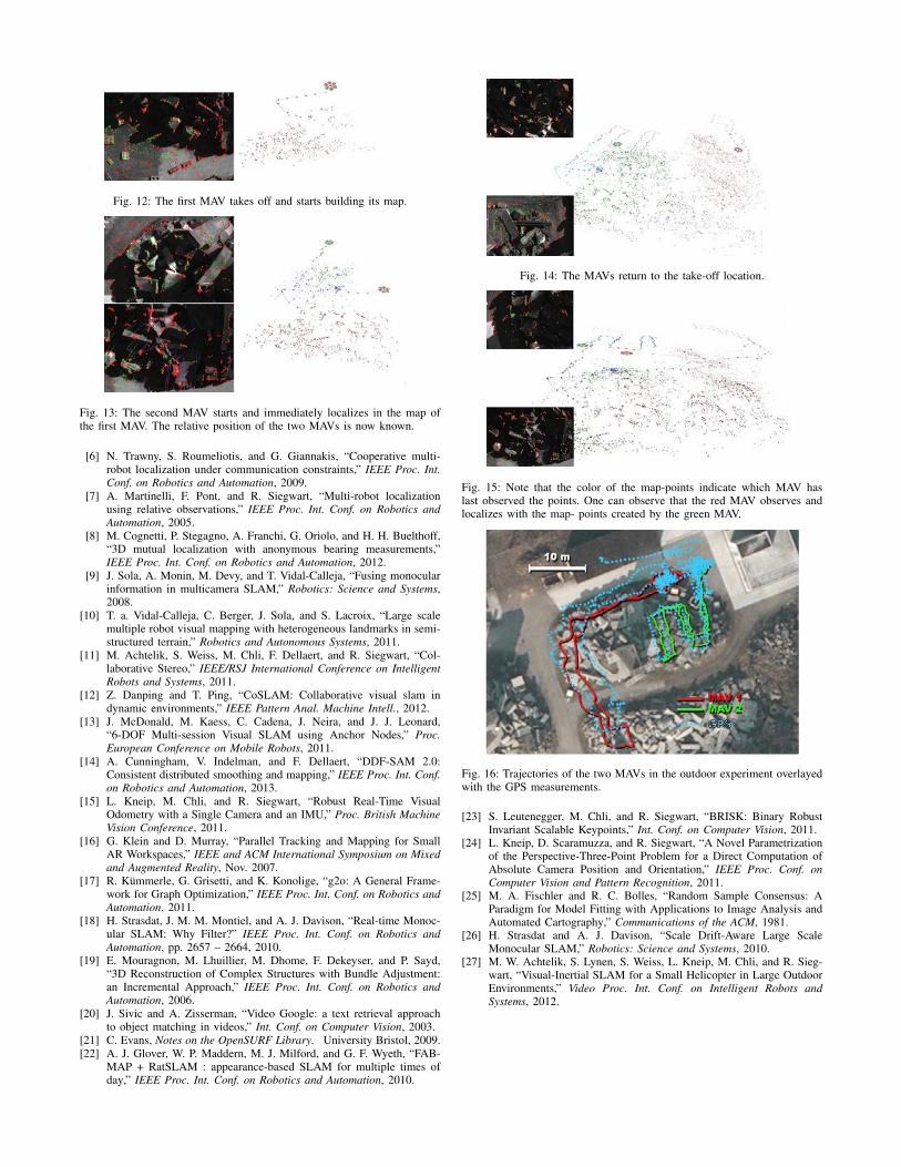
Fig. 12: The first MAV takes off and starts building its map.
Fig. 13: The second MAV starts and immediately localizes in the map ofthe first MAV. The relative position of the two MAVs is now known.
[6] N. Trawny, S. Roumeliotis, and G. Giannakis, “Cooperative multi-robot localization under communication constraints,” IEEE Proc. Int.
Conf. on Robotics and Automation, 2009.
[7] A. Martinelli, F. Pont, and R. Siegwart, “Multi-robot localizationusing relative observations,” IEEE Proc. Int. Conf. on Robotics and
Automation, 2005.
[8] M. Cognetti, P. Stegagno, A. Franchi, G. Oriolo, and H. H. Buelthoff,“3D mutual localization with anonymous bearing measurements,”IEEE Proc. Int. Conf. on Robotics and Automation, 2012.
[9] J. Sola, A. Monin, M. Devy, and T. Vidal-Calleja, “Fusing monocularinformation in multicamera SLAM,” Robotics: Science and Systems,2008.
[10] T. a. Vidal-Calleja, C. Berger, J. Sola, and S. Lacroix, “Large scalemultiple robot visual mapping with heterogeneous landmarks in semi-structured terrain,” Robotics and Autonomous Systems, 2011.
[11] M. Achtelik, S. Weiss, M. Chli, F. Dellaert, and R. Siegwart, “Col-laborative Stereo,” IEEE/RSJ International Conference on Intelligent
Robots and Systems, 2011.
[12] Z. Danping and T. Ping, “CoSLAM: Collaborative visual slam indynamic environments,” IEEE Pattern Anal. Machine Intell., 2012.
[13] J. McDonald, M. Kaess, C. Cadena, J. Neira, and J. J. Leonard,“6-DOF Multi-session Visual SLAM using Anchor Nodes,” Proc.
European Conference on Mobile Robots, 2011.
[14] A. Cunningham, V. Indelman, and F. Dellaert, “DDF-SAM 2.0:Consistent distributed smoothing and mapping,” IEEE Proc. Int. Conf.
on Robotics and Automation, 2013.
[15] L. Kneip, M. Chli, and R. Siegwart, “Robust Real-Time VisualOdometry with a Single Camera and an IMU,” Proc. British Machine
Vision Conference, 2011.
[16] G. Klein and D. Murray, “Parallel Tracking and Mapping for SmallAR Workspaces,” IEEE and ACM International Symposium on Mixed
and Augmented Reality, Nov. 2007.
[17] R. Kummerle, G. Grisetti, and K. Konolige, “g2o: A General Frame-work for Graph Optimization,” IEEE Proc. Int. Conf. on Robotics and
Automation, 2011.
[18] H. Strasdat, J. M. M. Montiel, and A. J. Davison, “Real-time Monoc-ular SLAM: Why Filter?” IEEE Proc. Int. Conf. on Robotics and
Automation, pp. 2657 – 2664, 2010.
[19] E. Mouragnon, M. Lhuillier, M. Dhome, F. Dekeyser, and P. Sayd,“3D Reconstruction of Complex Structures with Bundle Adjustment:an Incremental Approach,” IEEE Proc. Int. Conf. on Robotics and
Automation, 2006.
[20] J. Sivic and A. Zisserman, “Video Google: a text retrieval approachto object matching in videos,” Int. Conf. on Computer Vision, 2003.
[21] C. Evans, Notes on the OpenSURF Library. University Bristol, 2009.
[22] A. J. Glover, W. P. Maddern, M. J. Milford, and G. F. Wyeth, “FAB-MAP + RatSLAM : appearance-based SLAM for multiple times ofday,” IEEE Proc. Int. Conf. on Robotics and Automation, 2010.
Fig. 14: The MAVs return to the take-off location.
Fig. 15: Note that the color of the map-points indicate which MAV haslast observed the points. One can observe that the red MAV observes andlocalizes with the map- points created by the green MAV.
GPS
Fig. 16: Trajectories of the two MAVs in the outdoor experiment overlayedwith the GPS measurements.
[23] S. Leutenegger, M. Chli, and R. Siegwart, “BRISK: Binary RobustInvariant Scalable Keypoints,” Int. Conf. on Computer Vision, 2011.
[24] L. Kneip, D. Scaramuzza, and R. Siegwart, “A Novel Parametrizationof the Perspective-Three-Point Problem for a Direct Computation ofAbsolute Camera Position and Orientation,” IEEE Proc. Conf. on
Computer Vision and Pattern Recognition, 2011.[25] M. A. Fischler and R. C. Bolles, “Random Sample Consensus: A
Paradigm for Model Fitting with Applications to Image Analysis andAutomated Cartography,” Communications of the ACM, 1981.
[26] H. Strasdat and A. J. Davison, “Scale Drift-Aware Large ScaleMonocular SLAM,” Robotics: Science and Systems, 2010.
[27] M. W. Achtelik, S. Lynen, S. Weiss, L. Kneip, M. Chli, and R. Sieg-wart, “Visual-Inertial SLAM for a Small Helicopter in Large OutdoorEnvironments,” Video Proc. Int. Conf. on Intelligent Robots and
Systems, 2012.