par24vac cctv power supply manual · 5.amp meter display • power supply load is approaching...
TRANSCRIPT

CCTV Power Supply Manual16 Channel =(2 x 8Channel) with Dual Volt / Amp meter
24VAC 1.5U Rack Mount
Model: PAC-24RM1616(S84745)8
Overview: This PACOM Rack Mount CCTV Power Supplies provides 24VAC distributed via sixteen (16) PTC protected outputs for powering CCTV Cameras and other video accessories.
Notes: 2 Power On/Off Switches have been provided for each of the 8 Channels at the rear of the Rack case
Caution: Always test for correct output voltage ( 24VAC) before connecting power to cameras or other equipment. Temporarily power up the unit and measure the AC output voltage to avoid damage to devices. Then disconnect power before connecting external devices.
1. Mount unit in the desired rack location. To maintain Air Circulation, allow a minimum gap of 50mm on both sides and above the rack mount unit.2. Unplug Green terminal connector blocks from their sockets for easy installation. 3. Tech Tip: All Cameras with similar power cable length should be grouped together on the same terminal block.4. Connect cameras or other equipment power input cables to the screw terminals side by side in pairs. 5. Screw the terminals closed, making sure that there are no loose connections. Once this is done, insert the terminal block back into its correct slot. 6. Select the power on switch A or B for each of the 8 Channels 7. Connect the unit’s power cord to a 240VAC outlet and secure with safety clip. Switch on power to the unit. 8. Front-panel LEDs should illuminate Green if the Channel is not being used and Blue if the channel or channels are being used. Red if the Channel has a short circuit on the output lines. 9. Test the output at the camera end of each power cable to be sure voltage is within range as specified by the Camera manufacturer.
Tri-Colour LED status indicator for each output:
10. Volt meter operational range 5V - 69.9V 11. Amp meter operational range 200mA -8Amp For current load > 8 Amps ,<9 Amps Amp Meter display will Flash the current value For current Load Greater than 9.00 Amps, the Amp Meter display will read OL= Over Load.
12. RyA and RyB are N/C relay contact.
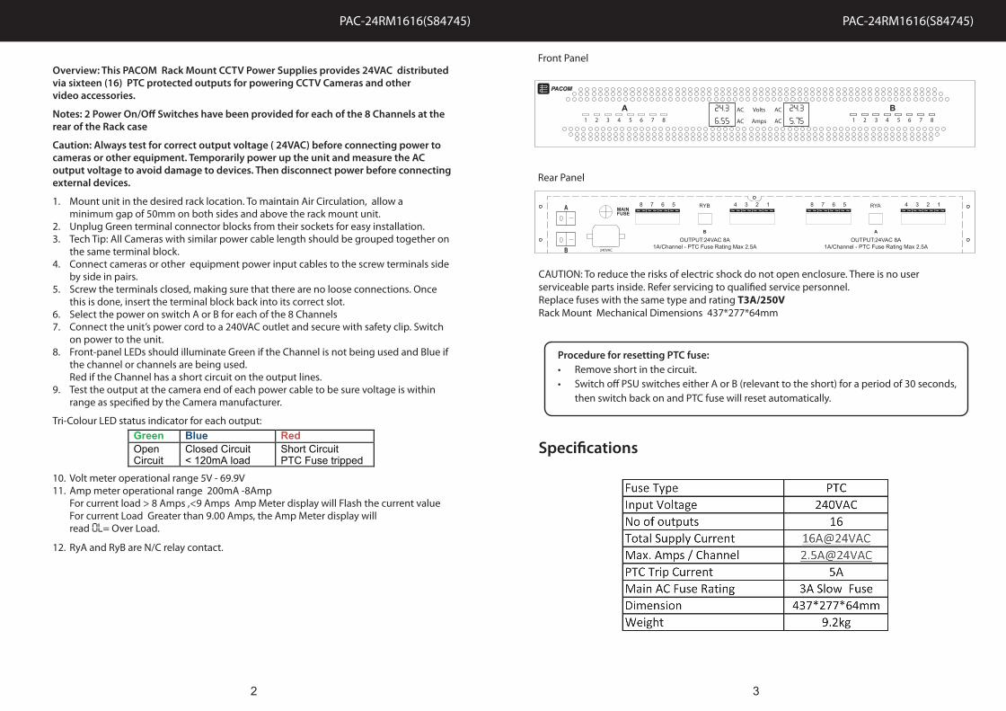
Front Panel
Rear Panel
PAC-24RM1616(S84745) PAC-24RM1616(S84745)
Green Blue Red Open Circuit
Closed Circuit < 120mA load
Short Circuit PTC Fuse tripped
Procedure for resetting PTC fuse:• Remove short in the circuit.• Switch off PSU switches either A or B (relevant to the short) for a period of 30 seconds, then switch back on and PTC fuse will reset automatically.
24.36.55
24.35.75
CAUTION: To reduce the risks of electric shock do not open enclosure. There is no user serviceable parts inside. Refer servicing to qualified service personnel.Replace fuses with the same type and rating T3A/250VRack Mount Mechanical Dimensions 437*277*64mm
2 3
Specifications
PAC-24RM1616(S84745) PAC-24RM1616(S84745)PAC-24RM1616(S84745)
4 5
12AWG55m
14AWG35m
16AWG22m
18AWG14m
20AWG9m
22AWG8m
12AWG73m
14AWG46m
16AWG29m
18AWG18m
20AWG12m
22AWG7m
12AWG110m
14AWG69m
16AWG44m
18AWG27m
20AWG18m
22AWG17m
12AWG138m
14AWG87m
16AWG55m
18AWG34m
20AWG22m
22AWG21m
12AWG184m
14AWG116m
16AWG73m
18AWG46m
20AWG30m
22AWG29m
24AWG32m
24AWG16m
24AWG10m
24AWG8m
24AWG6m
24AWG5m
24AWG3m
22AWG43m
20AWG44m
18AWG69m
16AWG109m
14AWG174m
12AWG276m
22AWG86m
20AWG87m
18AWG137m
16AWG218m
14AWG348m
12AWG552m
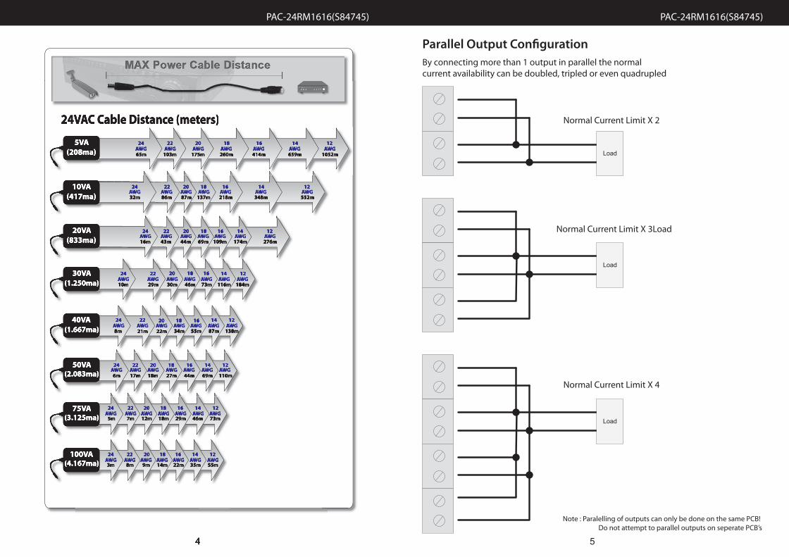
24VAC Cable Distance (meters)
24AWG65m
22AWG103m
20AWG175m
18AWG260m
16AWG414m
14AWG659m
12AWG
1052m
5VA(208ma)
10VA(417ma)
20VA(833ma)
30VA(1.250ma)
40VA(1.667ma)
50VA(2.083ma)
75VA(3.125ma)
100VA(4.167ma)
4
12AWG55m
14AWG35m
16AWG22m
18AWG14m
20AWG9m
22AWG8m
12AWG73m
14AWG46m
16AWG29m
18AWG18m
20AWG12m
22AWG7m
12AWG110m
14AWG69m
16AWG44m
18AWG27m
20AWG18m
22AWG17m
12AWG138m
14AWG87m
16AWG55m
18AWG34m
20AWG22m
22AWG21m
12AWG184m
14AWG116m
16AWG73m
18AWG46m
20AWG30m
22AWG29m
24AWG32m
24AWG16m
24AWG10m
24AWG8m
24AWG6m
24AWG5m
24AWG3m
22AWG43m
20AWG44m
18AWG69m
16AWG109m
14AWG174m
12AWG276m
22AWG86m
20AWG87m
18AWG137m
16AWG218m
14AWG348m
12AWG552m
24VAC Cable Distance (meters)
24AWG65m
22AWG103m
20AWG175m
18AWG260m
16AWG414m
14AWG659m
12AWG
1052m
5VA(208ma)
10VA(417ma)
20VA(833ma)
30VA(1.250ma)
40VA(1.667ma)
50VA(2.083ma)
75VA(3.125ma)
100VA(4.167ma)
Parallel Output Configuration
Load
Load
Load
By connecting more than 1 output in parallel the normal current availability can be doubled, tripled or even quadrupled
Normal Current Limit X 2
Normal Current Limit X 3Load
Normal Current Limit X 4
Note : Paralelling of outputs can only be done on the same PCB! Do not attempt to parallel outputs on seperate PCB’s
PAC-24RM1616(S84745) PAC-24RM1616(S84745)
6 7
Troubleshooting
1. Power does not turn on • Check front panel leds and rear main fuse• Ensure power cord is firmly in its socket and switch
A and B are in the on position• Ensure you have 240VAC supply to the Power
Supply Unit
2. led’s are RED even • To reset PTC , turn of power and wait for 30 sec,then restart unit though there is no short circuit
3. Voltage drop is large • Use thicker guage wire
4. Camera case is hot • Check that the correct voltage is supplied tothe camera
5. Amp Meter display • Power Supply load is approaching maximum current limitFlashes continously
6. Amp Meter display •reads OL
Power Supply unit has exceeded its maximum load capacity. Disconnect 1 or more devices until Amp Meter shows a reading less than the maximum capacity.