parad ise datacom - ab · pdf fileor hoxxx-x ratings on the cable and the connector ends...
TRANSCRIPT

Doc Ref: p:\p500\d-wp\p500.h
Installation and Operating Handbook
P500 1:8 Redundancy Controller,P520 Data Switching Module
(Universal Interface) andP525 Transponder Switch
(For applications using P200, P230,P300 Series and P400 Series
Satellite Modems)
Handbook Issue 5, Thu 25 Nov, 1999Covering Software Versions V1.20 or later
D A T A C O M
P A R A D I S E
Paradise Datacom Ltd. Paradise Datacom LLC.Tower Business Park 1012 E. Boal Avenue
Tiptree, Essex, CO5 0LX, England. Boalsburg, PA 16827, U.S.A.Phone 01621 816655 (Int + 44 1621...). Phone 814-466-6275 (Int + 1 814...)
Fax 01621 819929. Fax 814-466-3341http://www.paradise.co.uk http://www.paradisedata.com
IMPORTANT NOTE: THE INFORMATION AND SPECIFICATIONSCONTAINED IN THIS DOCUMENT SUPERSEDE ALL PREVIOUSLY
PUBLISHED INFORMATION CONCERNING THIS PRODUCT -SPECIFICATIONS MAY CHANGE WITHOUT NOTICE

Table of Contents
1 TELECOMMUNICATIONS TERMINAL DIRECTIVE,EMC AND SAFETY NOTICES . . . . . . . . . . . . . . . . . . . . 1
2 INTRODUCTION . . . . . . . . . . . . . . . . . . . . . . . . . . . . . . . . 3
3 DESCRIPTION . . . . . . . . . . . . . . . . . . . . . . . . . . . . . . . . . . 53.1 OUTLINE DESCRIPTION . . . . . . . . . . . . . . . . . . . . . . . . . 53.2 P500 FRONT PANEL DESCRIPTION . . . . . . . . . . . . . . . . . 113.3 P520 REAR PANEL DESCRIPTION . . . . . . . . . . . . . . . . . . 12
4 THEORY OF OPERATION . . . . . . . . . . . . . . . . . . . . . . . 14
5 SUMMARY OF SPECIFICATIONS - P500/P520 . . . . 25
6 SUMMARY OF SPECIFICATIONS - P525 . . . . . . . . . . 29
7 INSTALLATION AND CONFIGURATION . . . . . . . . 307.1 WARNING . . . . . . . . . . . . . . . . . . . . . . . . . . . . . . . . . . . . 307.2 UNPACKING . . . . . . . . . . . . . . . . . . . . . . . . . . . . . . . . . . 307.3 VISUAL INSPECTION OF EQUIPMENT . . . . . . . . . . . . . . 307.4 BEFORE INSTALLING IN A RACK . . . . . . . . . . . . . . . . . 307.5 CONFIGURING THE BIM AND TIMS . . . . . . . . . . . . . . . 327.6 AFTER INSTALLATION . . . . . . . . . . . . . . . . . . . . . . . . . . 357.7 POWER UP . . . . . . . . . . . . . . . . . . . . . . . . . . . . . . . . . . . . 35
8 MENU SYSTEM . . . . . . . . . . . . . . . . . . . . . . . . . . . . . . . . . 368.1 CONFIGURING THE UNIT . . . . . . . . . . . . . . . . . . . . . . . . 368.2 OPERATION . . . . . . . . . . . . . . . . . . . . . . . . . . . . . . . . . . . 388.3 CHANGE . . . . . . . . . . . . . . . . . . . . . . . . . . . . . . . . . . . . . . 398.4 SETUP . . . . . . . . . . . . . . . . . . . . . . . . . . . . . . . . . . . . . . . . 508.5 TEST . . . . . . . . . . . . . . . . . . . . . . . . . . . . . . . . . . . . . . . . . 508.6 LOG . . . . . . . . . . . . . . . . . . . . . . . . . . . . . . . . . . . . . . . . . . 518.7 INFORMATION . . . . . . . . . . . . . . . . . . . . . . . . . . . . . . . . 51
9 LOG . . . . . . . . . . . . . . . . . . . . . . . . . . . . . . . . . . . . . . . . . . . . 529.1 GENERAL . . . . . . . . . . . . . . . . . . . . . . . . . . . . . . . . . . . . . 529.2 HARD COPY . . . . . . . . . . . . . . . . . . . . . . . . . . . . . . . . . . . 529.3 PRINTER LEAD . . . . . . . . . . . . . . . . . . . . . . . . . . . . . . . . . 53
10 FAULT/ACTION TABLE . . . . . . . . . . . . . . . . . . . . . . . . 54

APPENDIX A: P500/P520 CONNECTOR PINOUTS . . . 55
APPENDIX B: P550 CONNECTOR PINOUTS - BIM . . . 58
APPENDIX C: P551 CONNECTOR PINOUTS - TIM . . . 61
APPENDIX D: DATA/CONTROL CABLE DETAILS . . 64
APPENDIX E: P525 TRANSPONDER SWITCH . . . . . . . 71
APPENDIX F: TROUBLESHOOTING GUIDE . . . . . . . . . 73
APPENDIX G: P560 BACKWARD ALARM PATCHINTERFACE . . . . . . . . . . . . . . . . . . . . . . . . . . . . . . . . . . . . 74

1 TELECOMMUNICATIONS TERMINAL DIRECTIVE, EMC AND SAFETYNOTICES - PLEASE READ BEFORE INSTALLATION AND USE
TELECOMMUNICATIONS TERMINAL DIRECTIVE
In accordance with the Telecommunications Terminal Directive 91/263/EEC, thisequipment is not intended for direct connection to the Public TelecommunicationsNetwork.
EMC (ELECTROMAGNETIC COMPATIBILITY)
This information applies for units manufactured after January 1996,Serial Number 0107 onwards. The P500/P520 Redundancy Controllerand Data Switching Module, and the P525 Transponder Switch havebeen shown to comply with the following standards:
Emissions: EN 55022 Class B; Limits and methods of measurement of radiointerference characteristics of Information Technology Equipment.
Immunity: EN 50082 Part 1; Generic immunity standard, Part 1: Domestic,commercial and light industrial environment.
To be sure that the System will maintain compliance with these standards please ensurethat the following points are observed:
1) The equipment MUST BE OPERATED WITH ITS COVERS ON AT ALLTIMES. If it is necessary to remove a cover for whatever reason, then you mustensure that the cover is correctly refitted before normal operation.
2) Damage to the front panel keyboard membrane or mechanical damage to thechassis could invalidate compliancy. Please contact the factory if damage occursfor advice on continued operation.
3) For the baseband data interfaces all ’D’ type connectors must have groundingfingers on the plug shell to guarantee continuous shielding. The back-shells mustcomply to the requirements of VDE 0871 and FCC 20708, providing at least 40dB of attenuation from 30 MHz to 1 GHz. A good quality cable with acontinuous outer shield, correctly grounded, must be used.
4) Connections to the transmit and receive IF interfaces of the P525 TransponderSwitch must be made with double screened coaxial cable - for example RG223/U.
Installations which ignore these requirements will invalidate the compliancy to EMCspecifications.
P500.H P500/P520 Installation and Operating Handbook Page 1

ELECTRICAL SAFETY
To ensure operator safety, the P500/P520 Redundancy Controller and Data SwitchingModule, and the P525 Transponder Switch have been shown to comply with thefollowing safety standard:
EN 60950: Safety of Information Technology Equipment, including electricalbusiness machines.
Prior to installation and operation, ensure that the following points are observed:
EnvironmentalThe equipment is designed to operate in a static 19 inch rack system conforming toIEC 297-2. Operation in transportable installations and vehicles equipped with themeans of providing a stable environment is permissible. Operation in vehicles, shipsor aircraft without means of environmental conditioning may invalidate safetycompliancy - please contact the factory for further advice. Operation in anenvironment outside the stated specifications will also invalidate safety compliancy.
The System must not be operated in an environment where the unit is exposed to:
* Un-pressurised altitudes greater than 2000 metres* Extremes of temperature outside the stated operating range* Excessive dust* Moisture, or humid atmospheres above 95% RH* Excessive vibration* Flammable gases* Corrosive or explosive atmospheres
InstallationThe equipment is classified in EN 60950 as a pluggable equipment class A forconnection to the mains supply. It has TWO mains inlets, and as such it is providedwith TWO mains inlet cords suitable for use in the country of operation. In normalcircumstances this will be of an adequate length for installation in a rack. If themains cable is too short then any replacement must have a similar type fuse (if fitted)and be manufactured to a similar specification. For example, look for HAR, BASECor HOXXX-X ratings on the cable and the connector ends marked with BS1636A (UKfree plug 13 amp); BSI, VDE, NF-USE, UL, CSA, OVE, CEBEC, NEMKO, DEMKO,SETI, IMQ, SEV and KEMA-KEUR for the IEC 6 amp free socket.
The installation and connection to the mains supply must be made in compliance tolocal or national wiring regulations for a category II impulse over-voltage installation.The positioning of the equipment must be such that the mains supply socket outletsfor the equipment should be near the equipment and easily accessible or that thereshould be another suitable means of disconnection from the mains supply.
The equipment is designed to operate from a TN type power supply system asspecified in EN 60950. This means a system that has separate earth, line and neutralconductors. The equipment is not designed to operate with an IT power systemwhich has no direct connection to earth.
P500.H P500/P520 Installation and Operating Handbook Page 2

2 INTRODUCTION
The P500 1:8 Redundancy Controller and P520 Data Switching Module form the basisof a system, which, in conjunction with P200 series or P400 series Satellite Modems,provides automatic protection of traffic circuits in the case of equipment failure, givingthe best possible availability. The P500/P520 supports the following interface types:
* RS422 DCE* V.35 DCE* X.21 DCE and DTE* G.703 64 kbps co-directional* 1.544 Mbps T1* G.703 2.048 Mbps 75 ohms unbalanced and 120 ohms balanced
Paradise Datacom has chosen to use the EIA 530 standard connector type on the P500switch to support all of the above electrical interface standards, with the exception ofG.703 2.048 Mbps 75 ohms unbalanced which uses separate BNC connectors.
Note that when switching P200 series modems different interface types cannot be mixedwithin a 1:N group. However for P300 Series modems, or P400 series modems (wherethe backup modem is equipped with a P1442 or P1442 multi-standard interface card)then the electrical interfaces can be mixed within the group. P300 and P400 series modemsmay also be mixed within a 1:N redundancy group, provided the backup modem isspecified highly enough to provide a superset of the features of all the traffic modems.
If all Modems within a redundancy group are connected to the same up/downconverter,a very simple configuration is possible. However, where operation with more than oneup/downconverter is required, the user may add the P525 Transponder switch. This IFbridging and switching unit permits as many converters as there are Traffic Modems.
With the goal of providing increased availability in mind, the P500 and P520 have beendesigned to be as robust as possible, and include the following key reliability features:
* Normal traffic paths are maintained, error free, even if AC power is removed, orthe P500 Controller is removed.
* The P500 Controller has twin, redundant power supplies.
* A Traffic Interface Module (TIM), carrying live traffic, can be completely removedfrom the P520, with its cables still attached, and traffic will be maintained.
* Traffic Interface Modules (TIMs) and the Backup Interface Module (BIM) can bereplaced without interruption of other traffic circuits.
* The traffic interfaces are contained within the switching system, unlike someother 1:N systems.
* The only common element - the P520 backplane - is completely passive.
P500.H P500/P520 Installation and Operating Handbook Page 3

* For all critical signals, the BIM and TIM backplane connectors have a minimumof two pins per signal, obviating a single-point failure mechanism.
These terms and features are fully explained in the sections which follow. This handbookdescribes the hardware, how it works, and how to install and configure the P500/P5201:8 Redundancy System.
P500.H P500/P520 Installation and Operating Handbook Page 4

3 DESCRIPTION
3.1 OUTLINE DESCRIPTION
The P500/P520 together comprise a 6U high rack-mounting unit, 534 mm deep. Figures1 and 2 show the front and rear panels of the P500/P520.
P500 Redundancy Controller
The P500 is a 3U high unit, which plugs into the P520 chassis. The P500 contains thecontrol processor, front panel LCD display, keypad, System Summary LED indicators,and audible alarm sounder. The Operator is prompted by messages displayed on theLCD to enter data via the keyboard. In this way the P500/P520 may be configured foruse and the setup changed, if necessary. The LEDs provide a quick visual indication ofthe operational status of the unit itself, and the entire system. The monitor port permitsconnection of a PC or serial printer to obtain a dump of the internal traffic log, or theunit’s configuration.
The P500, built around a single board IBM PC clone, is the ’intelligence’ for the entiresystem, and stores configuration data for all of the installed modems, so that in the eventof a failure of an on-line Traffic Modem, the Backup Modem can be re-programmed tomatch the configuration of the failed unit. Switch commands are then routed to the P520Data Switching Module, so that data signals are re-routed accordingly. The same user-friendly interface that is the trademark of other Paradise products is an important featureof this unit, giving the User clear, unequivocal instructions and help.
Re-programming of the Backup Modem takes place over the RS485 remote control bus.This bus can also be shared with an external M&C computer. Paradise Datacom’s multi-product M&C software can be used unmodified. The RS485 bus is simply connecteddirectly to the Redundancy Switches in the system. The RS485 bus passes through theP500 via two connectors at the rear of the unit.
Alarms from the Traffic Modems and Backup Modem are concentrated by the P520 DataSwitching Module, and fed into the P500. Copies of all of these alarms are displayed bycoloured LEDs on the front panel of the unit. The Operator can, at a glance, view thestatus of the entire system. The controller processes all of the alarm information, andgenerates summary alarm relay closures, available at the rear of the P520, which can beconnected to the main Station M&C system if required. There are summary alarms forthe Traffic and Backup Modems, and a Unit Fault, Prompt and Deferred Alarms for theP500 itself.
The P500 provides control outputs for the P520 Data Switching Module, and controloutputs to drive a P525 Transponder Switch, if required. The P500 can be configured toswitch a failed unit automatically in the event of either Unit Faults (hardware faultswithin a unit, such as a power supply), Traffic Faults (such as loss of demod lock), orboth. Full manual control of the system is also possible from the front panel. In this case,a Traffic Modem can be deliberately switched into standby, and a Backup Modemswitched into its place, even if no fault condition exists.
P500.H P500/P520 Installation and Operating Handbook Page 5

The LCD display gives ’plain English’ messages concerning the system status. Unlikeother manufacturer’s systems, the User can see immediately the status of the system, anddoes not have to spend several minutes trying to determine what has occurred.
In keeping with all Paradise Datacom products, the unit incorporates a full event log,which records each event, with a time-stamp, as it occurs. The maximum number of logentries is 500, and the User can scroll backwards or forwards through the entries,viewing them on the LCD display, or send the log to a serial device (PC or Printer)connected to the monitor port on the front panel.
For maximum reliability, twin power supply inputs are provided (A and B) and the unitcan operate from either, or both supplies. In the case that the P500 suffers a catastrophicfailure, or both AC supplies are removed, the P500 has been designed to ’fail safe’, sothat the data will continue to be passed through to the intended Traffic Modems. Thusthe P500 could be powered down, removed and replaced without causing anyinterruption to traffic (unless the Backup Modem is in service).
P500.H P500/P520 Installation and Operating Handbook Page 6

P500.H P500/P520 Installation and Operating Handbook Page 7

P500.H P500/P520 Installation and Operating Handbook Page 8

P520 Data Switching Module
This is a 6U chassis unit, which comprises a completely passive backplane assembly,mounted in the middle of the unit, providing front and rear access. Into the rear of thebackplane, up to 8 Traffic Interface Modules (TIM, Paradise Part Number P551), and oneBackup Interface Module (BIM, Paradise Part Number P550) are plugged. The P500Controller is plugged into the front of the backplane, along with the two Power SupplyUnits (PSUs), Paradise Part Number P540. The P500 is secured in place by 4 quarter-turnfasteners.
The P551 Traffic Interface Module (TIM) is a unit comprising a PCB assembly mountedon a metal base plate. At the rear, there are several connectors, mounted on anoutwards-facing panel. Refer to Figure 2. From top to bottom these connectors are:
a) Modem Alarms connector - a 9 pin ’D’ type which carries 4 sets of Form ’C’ dryrelay contacts, which exactly mimic the alarm relays found in the Modem. TheModem’s relays are connected to the P520, so this connector permits the user to gainaccess to these alarms, if it is necessary.
b) Data Interface connector - a 25 pin ’D’ type, which is used for all data interface typesexcept G.703 2.048 Mbps 75 ohms unbalanced. The pin assignment conforms to theEIA 530 standard. The appendices at the rear of this manual give the details of thepin assignments which apply to the various electrical standards.
c) G.703 2.048 Mbps 75 ohms unbalanced interface - a pair of BNC connectors, whichare found alongside the main Data Interface connector.
d) Modem Interface connector - a 50 pin ’D’ type. All signals to and from a Modem areconnected here. This includes data, clock and control signals, alarm signals, and forIntelsat IDR operation, all backward alarm inputs and outputs, and all ESC voice anddata signals.
(Please note that for IDR operation, each TIM needs to be fitted with the P552 ESCSwitching Module card, and the P520 needs to be fitted with the P560 Backward AlarmPatch Interface)
Three LEDs, Backup (orange) Bridge (green) and RTI (orange) show the current state ofthe TIM, when viewed from the rear. (See note at the end of this Section concerningRTI.) The front of the TIM is fitted with two DIN 41612 backplane connectors, and apower connector, and the whole assembly is inserted into guides in the P520 chassis, andmates with a matching connector set on the backplane. It is held securely in place by twocaptive fasteners at the top and bottom of the rear plate. Details of the connector typesand pinouts are shown in Appendix C.
The P550 Backup Interface Module (BIM) is approximately half the size of the TIM, butvery similar to a TIM. Refer to Figure 2. On the rear plate it has the followingconnectors:
a) Modem Interface connector - a 50 pin ’D’ type which is identical in function to theconnector on the TIM.
P500.H P500/P520 Installation and Operating Handbook Page 9

b) Modem Alarms connector - a 9 pin ’D’ type which is identical in function to theconnector on the TIM.
c) External Over-ride Connector - a 9 pin ’D’ type. In certain applications, it may bedesirable to isolate the Backup Modem from control of the redundancy system inorder to permit its independent use as a 9th Traffic Modem, or to permit externaltesting. This can be accomplished by patching round the data and IF connections,and feeding in a TTL ’low’ signal or an external contact closure to this connector.This has the effect of releasing the Interface Tri-State and Tx Carrier Inhibit controllines on the Modems, and overrides the settings from the P500. The P500 willcontinue to display what it believes is the correct state, but it should be ignored.
PARADISE DATACOM DOES NOT RECOMMEND THIS MODE OF OPERATION,AND IN NO CIRCUMSTANCES SHOULD IT BE INVOKED WHEN A BACKUP ISIN PROGRESS. The entire philosophy of ’bridging’, around which this product isbased, permits the continuous testing of the Backup Modem using copies of thetransmit and receive signals of a selected traffic path, so as to minimise un-necessaryswitchovers. The architecture permits the switch software to examine the status ofboth Traffic and Backup paths and if the same fault is present on both, decides thatthe fault is due to an external condition, and a switchover will not occur.
Details of the connector types and pinouts are shown in Appendix C.
All the alarm information from Traffic Modems and the Backup Modem is concentratedon a 4 bit bus on the backplane, and is passed to the P500, where the alarm state isconstantly scanned. The backup and bridge commands to the unit are sent from the P500to the appropriate destination via the P520 backplane.
The two P540 Power Supply Units plug into the front of the unit, underneath the P500Controller. Figure 1 shows the exact location of these Power Supply Units, but it shouldbe noted that there is normally an access plate, which holds the supplies in place, fittedat the front of the unit, and which is secured by 4 quarter-turn fasteners. The P540 hasa On/Off switch located at the top right of the Module. It is recommended that thesupply be switched ’Off’ before it is inserted or removed. Four LED indicators displaythat each of the internal voltage rails (+5, -5, +12 and -12 volts) are functional. The twosupplies are designated ’A’ and ’B’, with ’A’ being on the left.
The P520 has been designed to permit the removal and insertion of TIMs and the BIMwhilst the system is ’live’, without causing any interruptions of traffic on other modems,to permit on-line maintenance of the system.
Note on RTI Mode: RTI (Receive/Transmit Inhibit) is used in applications where theUser wishes the Transmit Carrier to be inhibited until a gooddemod lock is obtained. This mode can be selected by selection ofthe appropriate switch on the TIM. This ‘hardware RTI‘ isprimarily for the P200 modems, as both P300 and P400 seriesmodems have this feature available within the modem software.
P500.H P500/P520 Installation and Operating Handbook Page 10

3.2 P500 FRONT PANEL DESCRIPTION
Please refer to Figure 1.
KeyboardThe keyboard is of the membrane type (an integral part of the front panel), and iscompletely sealed against penetration of liquids. The keys provide audible feedback -the internal microcomputer recognises that a key has been pressed, and makes anaudible ’beep’.
There are 15 keys in total - number keys in the range 0 to 9, an up arrow key (↑),down arrow key (↓), MAIN key, YES/ENTER key, and NO/PREV key.
LCD displayThis backlit display provides 2 lines of 40 characters each, and is highly legible evenin conditions of high ambient light. It provides detailed information about the statusand configuration of the unit, and when appropriate, prompts the User to enter datavia the keyboard.
Monitor portThis 8 pin DIN connector permits access to the traffic log, etc. Details are found inthe Appendices.
LED IndicatorsIn addition to three LED indicators which display the status of the P500 RedundancyController itself, the bottom half of the P500 front panel is entirely devoted todisplaying a complete summary of the system status, using LEDs. Thus the User maysee, at a glance, if a fault has occurred in any of the 8 Traffic or Backup Modems.The display shows Unit Faults, Rx Prompt Alarms, Tx Prompt Alarms, DeferredAlarms, and indicates whether the unit is ’on-line’ or in ’standby’.
NOTE: The System Status Display shows a second Backup Modem position, BU2.In this application, only a single Backup Modem is used (BU1) and so theBU2 position is not used, and should be ignored.
The Standby LEDs are orange in colour, and only one LED in the Standby row willbe illuminated at any one time. All the others are bi-colour (red/green). The bi-colourLEDs will show green for a ’good’ condition, and red for a ’fault’ condition.
P500.H P500/P520 Installation and Operating Handbook Page 11

3.3 P520 REAR PANEL DESCRIPTION
Please refer to Figure 2. At the rear of unit are all of the connectors necessary for theUser to interface the P500/P520 to the outside world; terrestrial data connection, alarms,remote control, AC power and so on. The rear panel connectors are:
IEC mains power connectors and fuseFor maximum reliability, the P500/P520 is designed to operate from twoindependent supplies of 230 volts AC. The IEC connectors also include a fuse,which is standard 20 mm type, rated 2A, of the slow-blow (time delay) variety.Always replace the fuse with one of the same type and rating.
Alarms connectorThis is a 15 pin male ’D’ type connector, which provides access to the variousform ‘C’ relay contacts that indicate alarm conditions. In addition to providingthree alarm outputs indicating the status of the P500 itself (Unit Fault, PromptMaintenance and Deferred Maintenance), this connector also carries summaryModem alarms (Unit, Prompt Tx, Prompt Rx, and Deferred). Thus, for example,any Modem displaying a unit fault would cause the summary Unit Fault alarmrelay to be activated. Full details of the connector type and pinout are given inAppendix A. The behaviour of these alarms is defined in the Section titled’Fault/Action Table’.
RS485 In connectorThis is a 9 pin female ’D’ type connector, into which is plugged the M&Ccomputer side of the RS485 Bus. This provides single point access to all theModems connected to the P500. Pin details are shown in Appendix A.
RS485 Out connectorThis is a 9 pin male ’D’ type connector. This is where the ’Local’ RS485 bus isconnected to the P500, and provides the connection point for the Traffic andBackup Modems which are being controlled by the switch. Pin details are shownin Appendix A. A suitable cable is also shown in Figure 13.
IMPORTANT NOTE: The RS485 connectors have been designed so that if the P500Controller is removed for any reason, bus connectivity can be maintained byremoving the cables connected to ’RS485 In’ and ’RS485 Out’ and simply connectingthem together. This bypasses the P500 altogether, and the Modem side and M&CComputer side of the RS485 Bus are then connected together.
Auxiliary 1 ConnectorThis connector provides:
* Fused power supply voltages (+5 and +12 volts). These supplies are diode’OR’ed from the A and B power supplies.
* 4 open-collector outputs, under the control of the P500 processor. The signalscomprise a 3 bit address, corresponding to the number of the Traffic path in
P500.H P500/P520 Installation and Operating Handbook Page 12

question, and a further control line to indicate whether the selected Modemshould backup or bridge.
* 4 un-committed open-collector outputs, under the control of the P500processor.
* An External Acknowledge input, which can be either an external contactclosure to ground, or a TTL ’low’ signal. This is used to clear the AudibleAlarm Sounder remotely, and to clear summary alarm closures, if thesoftware has been configured by the user to do this.
Pin details are shown in Appendix A.
Auxiliary 2 ConnectorThis connector provides:
* Fused power supply voltages (+5 and +12 volts). These supplies are diode’OR’ed from the A and B power supplies.
* 8 open-collector outputs, under the control of the P500 processor. They areused to indicate which, if any, of the Traffic Modems is being substituted bythe Backup Modem. These can be connected to a station-wide M&C system,if desired.
* An External Acknowledge input, which can be either an external contactclosure to ground, or a TTL ’low’ signal. This is used to clear the AudibleAlarm Sounder remotely, and to clear summary alarm closures, if thesoftware has been configured by the user to do this.
Pin details are shown in Appendix A.
P500.H P500/P520 Installation and Operating Handbook Page 13

4 THEORY OF OPERATION
Figure 3 illustrates the P500/P520 redundancy concept, when the group of Modems isconnected to a single up/downconverter. All the key elements are shown in this onediagram, including data and IF connectivity, RS485 bus connections, etc. The systemcomprises a maximum of 8 Traffic Modems, a Backup Modem, and the P500/P520hardware. All IF inputs and outputs are passively split and combined. All modems arein remote control mode, and are connected to the P500 redundancy controller via anRS485 multi-drop bus. All modems within a system have a unique bus address. Thispermits the controller to interrogate any modem, to determine and store itsconfiguration, and to send any stored configuration to the Backup Modem.
It is important to note that the redundancy controller itself cannot be used to changeindividual configuration parameters of modems within the system. This must be doneeither locally, or via the multi-product M&C software which Paradise can provide. P200series modems need to be placed in remote mode for the system to function correctly.P300 and P400 Series Modems however allow the configuration to be read over theremote M&C port even when in local control and so P400 series modems can be left inlocal control, except for the backup which DOES require remote configuration & henceto be set in remote mode.
The P500 and P520 are shown in more detail in Figures 4 and 5.
Of fundamental importance to this system is the fact that, for the single transpondercase, IF switching is not done in a centralised location - it is distributed. Each Modemis fitted with an RF relay (which is open in the power-off state), which is normallycontrolled by the internal software of the Modem. However, it has a direct hardwareconnection which will over-ride the processor setting, and turn the carrier off. Thus, allmodems are connected to a passive IF combiner, and the IF outputs from a Traffic orBackup Modem can be enabled or disabled via a hardware command from the controller.(See the rear of this section for details of IF splitting/combining for single multipletransponders, and in particular, see the information at the end of this Manual on theP525 Transponder Switch.)
On the receive IF side, all of the Traffic Modems and the Backup Modem are fed withidentical signals from a passive IF distribution system. Thus, the Backup Modem can beset to demodulate any of the input carriers to any of the Traffic Modems.
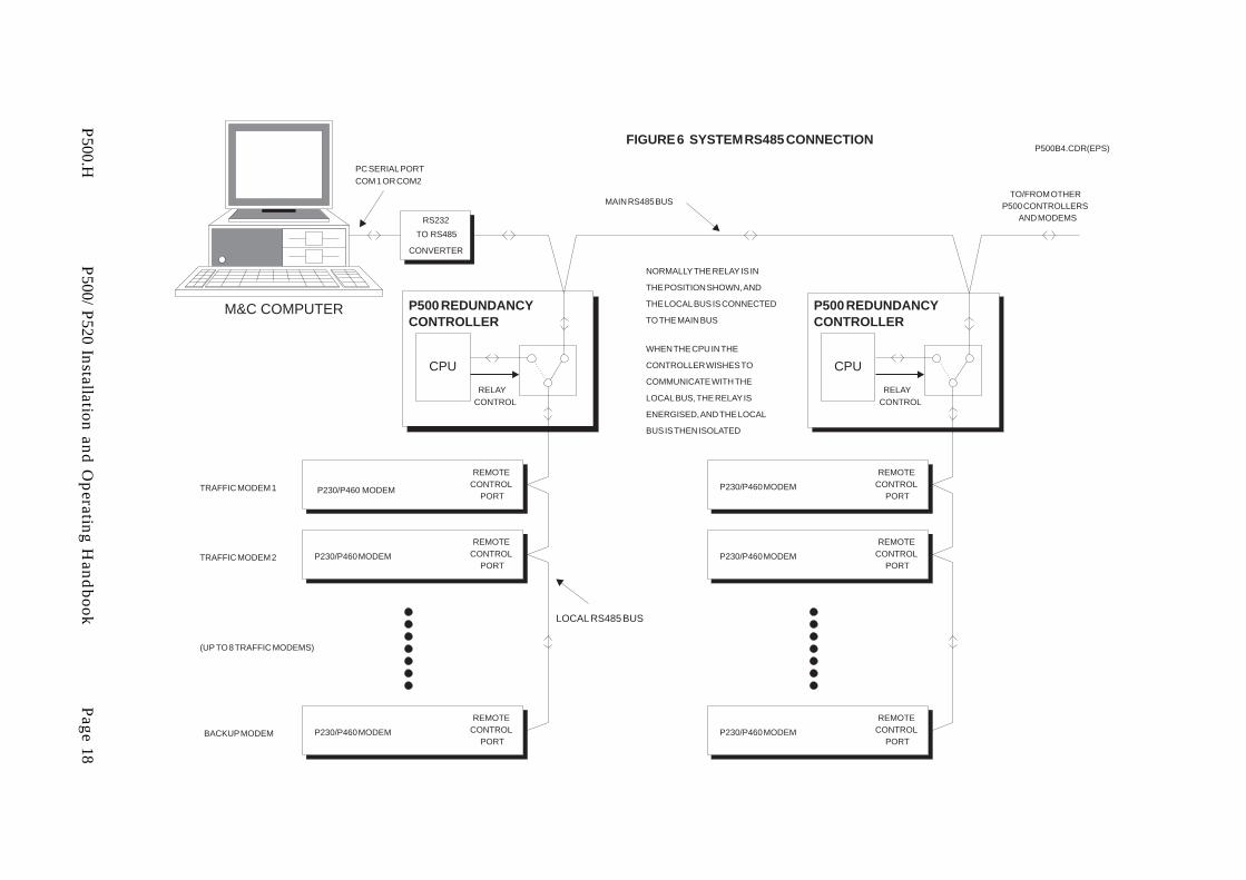
A ’Local’ RS485 bus connects the P500 Controller to each of the Traffic Modems and theBackup Modem. This ’Local’ RS485 bus is normally routed directly through the P500, sothat the M&C Computer, connected externally, can monitor and control all of theModems within a system, or multiple systems. In the case where the P500 needs controlof the Local RS485 bus, a relay within the P500 isolates the M&C side of the bus (the’Main’ bus), and connects the P500’s CPU to the ’Local’ bus. This permits the P500 toeither learn a particular Modem’s configuration, or to re-program the Backup Modem.Figure 6 illustrates both the ’Main’ and ’Local’ RS485 bus connections.
P500.H P500/P520 Installation and Operating Handbook Page 14
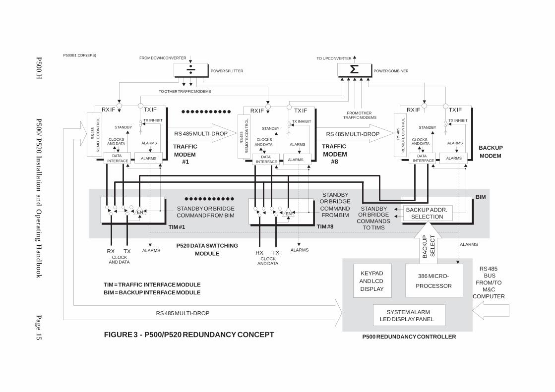
FIGURE 3 - P500/P520 REDUNDANCY CONCEPT
P500B1.CDR (EPS)
BACKUPMODEM
TO OTHER TRAFFIC MODEMS
FROM OTHERTRAFFIC MODEMS
POWER COMBINERPOWER SPLITTER
FROM DOWNCONVERTER TO UPCONVERTER
TRAFFICMODEM
#8
RX IF TX IF
TX INHIBIT
DATAINTERFACE
STANDBY
CLOCKSAND DATA ALARMS
RS
485
RE
MO
TE
CO
NT
RO
L
RX IF TX IF
TX INHIBIT
DATAINTERFACE
STANDBY
CLOCKSAND DATA
ALARMS
ALARMS
RS
485
RE
MO
TE
CO
NT
RO
L
RX IF TX IF
TX INHIBIT
DATAINTERFACE
STANDBY
CLOCKSAND DATA
ALARMS
ALARMS
RS
485
RE
MO
TE
CO
NT
RO
L
ALARMS
TIM #1 TIM #8
BIM
RX TXCLOCK
AND DATA
EN
RX TXCLOCK
AND DATA
EN
TRAFFICMODEM
#1
RS 485 MULTI-DROP RS 485 MULTI-DROP
P500 REDUNDANCY CONTROLLER
RS 485 MULTI-DROP
ALARMS
SYSTEM ALARMLED DISPLAY PANEL
KEYPADAND LCDDISPLAY
ALARMSALARMS
386 MICRO-
PROCESSOR
RS 485BUS
FROM/TOM&C
COMPUTER
P520 DATA SWITCHINGMODULE B
AC
KU
P
SE
LEC
T
BACKUP ADDR.SELECTION
STANDBY
TO TIMSCOMMANDSOR BRIDGE
STANDBY
FROM BIMCOMMANDOR BRIDGE
STANDBY OR BRIDGECOMMAND FROM BIM
TIM = TRAFFIC INTERFACE MODULEBIM = BACKUP INTERFACE MODULE
P500.HP500/
P520Installation
andO
peratingH
andbook
Page15

LED
STA
TU
S P
AN
EL
FR
ON
T P
AN
EL
KE
YP
AD
FR
ON
T P
AN
EL
LCD
DIS
PLA
YS
OU
ND
ER
SE
RIA
L P
OR
T(T
X O
NLY
)F
RO
NT
PA
NE
L LC
D D
ISP
LAY
FR
ON
T P
AN
EL
KE
YP
AD
SO
UN
DE
RLE
D S
TAT
US
PA
NE
LS
ER
IAL
PO
RT
(TX
ON
LY)
COM 1RS232
SU
MM
AR
Y S
YS
TE
M S
TAT
US
RE
LAY
OU
TP
UT
S
RS
485
INR
S48
5 O
UT
OUTPUT DRIVERS INPUT MONITORS
RA
M(2
ME
G)
I/0 BUS
FR
ON
T P
AN
EL
PE
RIP
HE
RA
L B
US
PS
U #
1
PS
U #
2
AC
AC
DC
DC
DIO
DE
S
HA
RIN
GN
ET
WO
RK
S
DC
SU
PP
LIE
SF
OR
INT
ER
NA
LU
SE
, AN
D F
OR
P52
0 A
ND
P52
5
8038
6C
PU
RO
M(0
.5 M
EG
)
CP
U C
AR
D
FIG
UR
E 4
- P
500
RE
DU
ND
AN
CY
CO
NT
RO
LLE
R
FRONT PANEL I/O
P50
0B2.
CD
R (E
PS
)
CO
NT
RO
L S
IGN
ALS
(E
G. T
RA
NS
PO
ND
ER
SW
ITC
H 1
AN
D 2
)
AU
XIL
IAR
Y 1
AN
D 2
CO
NT
RO
L S
IGN
ALS
TO
P52
0 /D
ATA
SW
ITC
HIN
G M
OD
ULE
4 LI
NE
S -
3 B
IT M
OD
EM
AD
DR
ES
S T
O B
IM A
ND
BA
CK
UP
/*B
RID
GE
CO
MM
AN
DT
O A
LL T
IMS
AN
D B
IM
ALA
RM
ST
RO
BE
S
ALA
RM
INP
UT
S F
RO
MT
RA
FF
IC A
ND
B
AC
KU
P M
OD
EM
S
RS
485/
RS
232
RS
485
BU
S
RE
LAY
AD
DR
ES
SD
EC
OD
ING
BA
TT
ER
Y-B
AC
KE
D
CO
NF
IGU
RAT
ION
AN
DT
RA
FF
IC L
OG
RA
M (8
K)
MU
LTI-
A/D
INP
UT
CO
NV
FR
OM
M&
C C
OM
PU
TE
RT
O M
OD
EM
S
P500.H P500/P520 Installation and Operating Handbook Page 16

9 PIN ’D’ TYPE CONNECTOR
75 O
HM
BN
C
FO
R 2
048
kbps
TX
D A
FIG
UR
E 5
- P
520
DA
TA S
WIT
CH
ING
MO
DU
LE
R te
rm
BA
CK
PLA
NE
BU
S
BA
CK
PLA
NE
BU
S
BA
CK
PLA
NE
BU
S
BA
CK
PLA
NE
BU
S
BA
CK
PLA
NE
BU
S
ET
CE
TC
RX
DR
X C
LKT
X D
TX
CLK
25 ’D
’ TY
PE
FE
MA
LE C
ON
NE
CT
OR
(EIA
530
STA
ND
AR
D P
INO
UT
)
50 PIN ’D’ TYPE CONNECTOR
50 PIN ’D’ TYPE CONNECTOR
TR
AF
FIC
IN
TE
RFA
CE
#1
25 PIN ’D’ TYPE CONNECTOR
4-P
OLE
C/0
RE
LAY
4-P
OLE
C/0
RE
LAY
4-P
OLE
C/0
RE
LAY
G.7
03 U
NB
AL
TX
D B
TX
CLK
A
TX
CLK
B
RX
D A
RX
D B
RX
CLK
A
RX
CLK
B
ET
C A
ET
C B
TX
INH
IBIT
STA
ND
BY
ALA
RM
S
(TT
L)
(TT
L)
TERRESTRIAL INTERFACE #8
ESC VOICE/DATA& BACK ALARMS
CO
NT
RO
LLE
R (T
TL)
ALA
RM
S, T
O
ALARMS
CO
NT
RO
LLE
R (T
TL)
ALA
RM
S, T
OTERRESTRIAL INTERFACE #2
TX
D A
TX
D B
TX
CLK
A
TX
CLK
B
RX
D A
RX
D B
RX
CLK
AR
X C
LK B
ET
C A
ET
C B
ALA
RM
S
BIM
TIM
TIM
TIM
9 PIN ’D’ TYPE CONNECTOR
BACKUP MODEM INTERFACE
TRAFFIC MODEMINTERFACE
BA
CK
UP
INT
ER
FAC
E
5 V
OLT
S A
5 V
OLT
S B
5 V
OLT
S
5 V
OLT
S A
5 V
OLT
S B
5 V
OLT
S
81
TX
INH
IBIT
STA
ND
BY
RELAY
DRIVERS
RELAYS AND
DRIVERS
RELAYS AND
DRIVERS
MO
DE
M
P50
0B3.
CD
R (E
PS
)
3 B
IT A
DD
RE
SS
OF
MO
DE
M T
O B
RID
GE
FR
OM
CO
NT
RO
LLE
R
OR
BA
CK
UP
BA
CK
UP
/*B
RID
GE
CO
MM
AN
D
1 O
F 8
DE
CO
DE
ALA
RM
ST
RO
BE
, FR
OM
CO
NT
RO
LLE
RA
LAR
M S
TR
OB
E
enen
en en
TO
BIM
AN
D A
LL T
IMS
TO
ALL
TIM
S
MO
DE
M S
ELE
CT
CO
MM
AN
DS
FR
OM
BIM
MO
DE
M
SE
LEC
T
CO
MM
AN
D
BA
CK
UP
/
CO
MM
AN
D
CO
NT
RO
LLE
R
*BR
IDG
E
FR
OM
FR
OM
BIM
MO
DE
M
SE
LEC
T
CO
MM
AN
D
BA
CK
UP
/
CO
MM
AN
D
CO
NT
RO
LLE
R
*BR
IDG
E
FR
OM
FR
OM
BIM
MO
DE
M
SE
LEC
T
CO
MM
AN
D
BA
CK
UP
/
CO
MM
AN
D
CO
NT
RO
LLE
R
*BR
IDG
E
FR
OM
NO
TE
: ES
C V
OIC
E/D
ATA
AN
D B
AC
KW
AR
D A
LAR
MS
WIT
CH
ING
NO
T S
HO
WN
FO
R C
LAR
ITY
ALARMS
P500.H P500/P520 Installation and Operating Handbook Page 17
RELAYCONTROL
CPU
P500 REDUNDANCYCONTROLLER
P230/P460 MODEM
REMOTECONTROL
PORT
P230/P460 MODEM
REMOTECONTROL
PORT
P230/P460 MODEM
REMOTECONTROL
PORT
RS232
TO RS485
CONVERTER
RELAYCONTROL
CPU
P500 REDUNDANCYCONTROLLER
P230/P460 MODEM
REMOTECONTROL
PORT
P230/P460 MODEM
REMOTECONTROL
PORT
P230/P460 MODEM
REMOTECONTROL
PORT
TO/FROM OTHER P500 CONTROLLERS
AND MODEMS
MAIN RS485 BUS
LOCAL RS485 BUS
TRAFFIC MODEM 1
TRAFFIC MODEM 2
BACKUP MODEM
(UP TO 8 TRAFFIC MODEMS)
PC SERIAL PORTCOM 1 OR COM2
M&C COMPUTER
NORMALLY THE RELAY IS IN
THE POSITION SHOWN, AND
THE LOCAL BUS IS CONNECTED
TO THE MAIN BUS
WHEN THE CPU IN THE
CONTROLLER WISHES TO
COMMUNICATE WITH THE
LOCAL BUS, THE RELAY IS
ENERGISED, AND THE LOCAL
BUS IS THEN ISOLATED
FIGURE 6 SYSTEM RS485 CONNECTIONP500B4.CDR(EPS)
P500.HP500/
P520Installation
andO
peratingH
andbook
Page18

The data and clock signals, to and from a Traffic Modem, are routed through a TrafficInterface Module (TIM), via a set of relays. This is arranged so that the de-energised(unpowered) state connects the data signals directly through to the Traffic Modem. Thusit can be seen that if the power supplies to the system are lost, or if a TIM carryingtraffic is removed, no interruption of the traffic will take place. It should also be notedthat in normal circumstances, where the Backup is not in service, no data is carriedthrough the P520 backplane - all data is routed via the TIM.
The concept of BRIDGING is fundamental to the understanding of the system. EachTIM includes line receivers, which are placed, in a high-impedance bridge mode, acrossthe Transmit Clock and Data lines being fed through the TIM. This produces a copy ofthese signals, which can be routed, via the P520 backplane, to the Backup InterfaceModule, and connected from there to the Backup Modem. All TIMs have lines connectedto a common backplane bus, but only one set of drivers is enabled at any one time, therest being held in a high impedance state. In this manner, copies of Tx Clock and Datafrom any selected Traffic Modem can be routed to the Backup Modem, without affectingthe particular Traffic Modem.
When not in a backup state, this provides an ideal way to keep the Backup Modemsupplied with data, and obviates the need for a clock and PRBS sequence generator,found in some other systems. Another obvious advantage of this arrangement is that itprovides an easy method of monitoring the incoming data - if both the Traffic andBackup Modems show that there is a loss of Tx clock from the terrestrial side, then itfairly obvious that there is an external problem - not a fault in a Traffic Modem. Thenormal traffic path, and a bridged path to the Backup Modem is shown in Figure 7.
Consider now the path the traffic takes when a backup occurs - that is, when dataintended for a Traffic Modem is deliberately re-routed to the Backup Modem. The relayswhich were connecting the Tx and Rx Clock and Data signals to the Traffic Modem areenergised, and the following occurs:
a) Terminating resistors (the value of which depends on the particular interface typeselected by the switches on the TIM) are switched across the Tx Clock and Datalines, thus maintaining correct impedance matching on the signal lines.
b) The bridging line receivers are enabled, which then supply the Backup Modemwith Tx Clock and Data signals.
c) A second set of high impedance line receivers, also bridging the clock and datalines is enabled, and continue to supply the original Traffic Modem with Clockand Data. (This is very important - if the original Traffic Modem loses clock anddata, then a Tx Traffic Fault Alarm will automatically be generated. If the P500has been configured to switch following Traffic Faults, this will result in thatparticular Traffic path being forced permanently into a fault condition, fromwhich it cannot automatically recover.)
d) On the receive side, Rx Clock and Data signals coming from the Backup Modem,via a common bus on the P520 backplane, are routed through the relays, and outof the 25 pin EIA 530 connector (or the 75 ohm BNC connector in the case ofG.703 2.048 Mbps 75 ohm unbalanced case).
The traffic paths are shown in Figure 8.
P500.H P500/P520 Installation and Operating Handbook Page 19

In the case of Intelsat IDR operation, ESC audio, data, and backward alarms are switchedby the P552 ESC Switching Module and P560 Backward Alarm Patch Interface.
The Backup Modem obviously needs to make its configuration match that of the TrafficModem in question. This is done using the RS485 remote control bus. After ’Setup’, theP500 interrogates, then stores the configuration of each Modem in non-volatile RAM.This is a complete definition, including TX and RX synthesizer frequencies, Tx powerlevel, clock modes, data rates, etc. Part of a backup or bridge operation will involve theController taking a stored configuration, and re-programming the Backup with thisconfiguration data. This approach, combined with passive IF distribution, means that theTransmit EIRP can be very accurately matched if the Backup Modem is put into service.The Backup Interface Module (BIM) accepts a 3 bit address from the P500 Controller,which is decoded into a 1-of-8 output, generating a Modem select line for each TIM. TheP500 also produces another control signal, which tells the TIM whether to go into backupor bridge mode. Thus, there are four control lines which completely define the hardwarestate of the P520. If the P500 Controller is powered down or removed from the system,the hardware defaults to bridging Traffic Modem 1. (Traffic Modem 1 is the leftmostTIM, when the P520 is viewed from the rear.)
For the P500 to determine the state of the Modems attached to the TIMs, the alarm relayclosures found at the rear of the Modem are connected to the each of the correspondingTIMs. Circuitry on each TIM monitors the relay closures, and generates logic signalsfrom them. From here, the logic signals drive an identical set of Form ’C’ relays, whichfeed the Alarms connector at the rear of the TIM. At the same time, the alarms arepassed to a four bit backplane bus, via tri-state drivers, providing the P500 with thealarm information. A strobe signal from the P500 Controller enables the driver, and thecontroller reads the Traffic Modem alarm state from each TIM, in a sequential scan. Atthe same time, the alarm strobe activates an open collector output, also connected to thebackplane bus. This permits the controller to determine if a TIM is actually present. Ifit is not, then any apparent alarms can be masked.
The software in the P500 Controller has the task of continuously scanning the alarm stateof the entire system, and taking the appropriate action if the criteria for performing abackup are met. These criteria are defined by the Operator, through the software menusystem. The behaviour of the software is explained in the ’MENU SYSTEM’ section.
Operation with more than one transponder is possible, with the addition of a P525Transponder Switch. In this case, instead of the switching being distributed among theTraffic and Backup Modems, the transmit IF switching is performed within the P525with a conventional ’cascaded baseball’ switch architecture. The P525 is controlled by theAuxiliary 2 connector on the rear panel of the P520. Key features of the transmit IFswitching are:
* When the Traffic Modems are in normal service, the Backup Modem output canbe directly monitored at the Test Access Port.
* If a switchover does occur, the failed Modem’s IF output is automatically routedto the Test Access Port, permitting easy examination.
P500.H P500/P520 Installation and Operating Handbook Page 20

On the receive side, each traffic path passes through a 3 dB power splitter. One port ofthe splitter passes directly to the Traffic Modem, whilst the other output is fed to anarray of RF switches, which permits the P500 Controller to bridge any desired IF input.Figure 9 shows a block diagram of the P525.
P500.H P500/P520 Installation and Operating Handbook Page 21

75 OHM BNC FOR 2048 kbps
TXD A
FIGURE 7 - P520 DATA SWITCHING MODULE - SHOWING NORMAL TRAFFIC PATH
R term
ETCETC RX D RX CLK TX DTX CLK
25 ’D’ TYPE FEMALE CONNECTOR(EIA 530 STANDARD PINOUT)
50 P
IN ’D
’ TY
PE
CO
NN
EC
TO
R
TRAFFIC INTERFACE #1
4-POLEC/0 RELAY
4-POLEC/0 RELAY
4-POLEC/0 RELAY
G.703 UNBAL
TXD B
TX CLK A
TX CLK B
RX D A
RX D B
RX CLK A
RX CLK B
ETC A
ETC B
TX INHIBIT
STANDBY
ALARMS
(TTL)
(TTL)
ES
C V
OIC
E/D
ATA
& B
AC
K A
LAR
MS
ALA
RM
S
TXD ATXD B
TX CLK A
TX CLK B
RX D ARX D B
RX CLK ARX CLK B
ETC AETC B
ALARMS
BIMTIM
BA
CK
UP
MO
DE
M
INT
ER
FAC
E
TR
AF
FIC
MO
DE
MIN
TE
RFA
CE
BACKUPINTERFACE
5 VOLTS A
5 VOLTS B
5 VOLTS
5 VOLTS A
5 VOLTS B5 VOLTS
8
1
TX INHIBIT
STANDBY
RE
LAY
DR
IVE
RS
RE
LAY
S A
ND
DR
IVE
RS
RE
LAY
S A
ND
DR
IVE
RS
MODEM
P500B5.CDR (EPS)
1 OF 8DECODE
enen
enen
FROM BIM
MODEM
SELECT
COMMAND
BACKUP/
COMMAND
CONTROLLER
*BRIDGE
FROM
ALA
RM
S
ARE ALSO ROUTED TO BACKUP
IF MODEM IS SELECTED BYCONTROLLER, TX CLOCK AND DATA
MODEM (BRIDGE MODE)
P500.HP500/
P520Installation
andO
peratingH
andbook
Page22

75 OHM BNC FOR 2048 kbps
TXD A
FIGURE 8 - P520 DATA SWITCHING MODULE - SHOWING BACKUP TRAFFIC PATH
R term
ETCETC RX D RX CLK TX DTX CLK
25 ’D’ TYPE FEMALE CONNECTOR(EIA 530 STANDARD PINOUT)
50 P
IN ’D
’ TY
PE
CO
NN
EC
TO
R
TRAFFIC INTERFACE #1
4-POLEC/0 RELAY
4-POLEC/0 RELAY
4-POLEC/0 RELAY
G.703 UNBAL
TXD B
TX CLK A
TX CLK B
RX D A
RX D B
RX CLK A
RX CLK B
ETC A
ETC B
TX INHIBIT
STANDBY
ALARMS
(TTL)
(TTL)
ES
C V
OIC
E/D
ATA
& B
AC
K A
LAR
MS
ALA
RM
S
TXD ATXD B
TX CLK A
TX CLK B
RX D ARX D B
RX CLK ARX CLK B
ETC AETC B
ALARMS
BIMTIM
BA
CK
UP
MO
DE
M
INT
ER
FAC
E
TR
AF
FIC
MO
DE
MIN
TE
RFA
CE
BACKUPINTERFACE
5 VOLTS A
5 VOLTS B
5 VOLTS
5 VOLTS A
5 VOLTS B5 VOLTS
8
1
TX INHIBIT
STANDBY
RE
LAY
DR
IVE
RS
RE
LAY
S A
ND
DR
IVE
RS
RE
LAY
S A
ND
DR
IVE
RS
MODEM
P500B6.CDR (EPS)
1 OF 8DECODE
enen
enen
FROM BIM
MODEM
SELECT
COMMAND
BACKUP/
COMMAND
CONTROLLER
*BRIDGE
FROM
ALA
RM
S
TX DATA AND CLOCKCONTINUE TO BE ROUTED
TO TRAFFIC MODEM
P500.HP500/
P520Installation
andO
peratingH
andbook
Page23

FIGURE 9 - IF SWITCHING - USING P525 TRANSPONDER SWITCHP500B7.CDR(EPS)
BRIDGE COMMAND #7
BRIDGE COMMAND #6
BRIDGE COMMAND #5
BRIDGE COMMAND #4
BRIDGE COMMAND #3
BRIDGE COMMAND #1
BRIDGE COMMAND #8
FROM DOWNCONVERTER #1
FROM DOWNCONVERTER #6
FROM DOWNCONVERTER #8
FROM DOWNCONVERTER #3
FROM DOWNCONVERTER #4
FROM DOWNCONVERTER #2
FROM DOWNCONVERTER #7
FROM DOWNCONVERTER #5
TO TRAFFIC MODEM #8
TO TRAFFIC MODEM #2
TO TRAFFIC MODEM #5
BRIDGE COMMAND #2
TO STANDBY MODEM
TO TRAFFIC MODEM #1
TO TRAFFIC MODEM #3
TO TRAFFIC MODEM #4
TO TRAFFIC MODEM #6
TO TRAFFIC MODEM #7
BACKUP COMMAND #1
BACKUP COMMAND #7
BACKUP COMMAND #6
BACKUP COMMAND #5
BACKUP COMMAND #4
BACKUP COMMAND #3
BACKUP COMMAND #2
TEST ACCESS
BACKUP COMMAND #8
TO UPCONVERTER #7
TO UPCONVERTER #6
TO UPCONVERTER #5
TO UPCONVERTER #4
TO UPCONVERTER #3
TO UPCONVERTER #2
TO UPCONVERTER #1
TO UPCONVERTER #8FROM STANDBY MODEM
FROM TRAFFIC MODEM #2
FROM TRAFFIC MODEM #4
FROM TRAFFIC MODEM #3
FROM TRAFFIC MODEM #8
FROM TRAFFIC MODEM #6
FROM TRAFFIC MODEM #1
FROM TRAFFIC MODEM #7
FROM TRAFFIC MODEM #5
RX TXP500.HP500/
P520Installation
andO
peratingH
andbook
Page24

5 SUMMARY OF SPECIFICATIONS - P500/P520
Equipment type 1:N Redundancy Controller system, with N = 8 maxBridging architecture. 80386 control processor
Dimensions and Weight 6 U chassis - 534 mm deep, 45 lbs (20 kgs)
Compatible Modems P200 Series Satellite Modems (P200, P200RS, orP230 D/I IBS/SMS Modems)
P300 Series Satellite ModemsP400 Series Satellite Modems (P420, P440, P460 or
P480)(P200 series Modem may not be mixed within aredundancy group. Any mix of P300 and P400series is allowed provided the backup is equivalentto the highest specified modem in the group)
Data Interfaces using RS422 DCE25 pin ’D’ type female V.35 DCEconnector, conforming X.21 DCE and DTEto the EIA 530 standard: G.703 64 kbps co-directional
1.544 Mbps T1G.703 2.048 Mbps 120 Ω balanced
Using 75 Ω BNC connectors: G.703 2.048 Mbps 75 Ω unbalanced
Modem Control Interface RS485 multi-drop, with 9 pin ’D’ type femaleconnector for ’in’, and 9 pin ’D’ type male for ’out’.
Operating Modes Fully AutomaticManual Backup or BridgeLockout facility (remove from group)Programmable Holdoff and Clear times, from 0 to999 seconds, in 1 second incrementsProgrammable threshold for lockout if switchingoccurs too frequently
Signal source, Backup Modem Any one of the 8 Traffic paths (Bridge Mode)
Switching conditions Switch to Backup Modem following:Tx Traffic Fault and Unit FaultsRx Traffic Fault and Unit FaultsRx and Tx Traffic Faults and Unit FaultsUnit Faults onlyLockout (Don’t switch)
P500.H P500/P520 Installation and Operating Handbook Page 25

IF Switching Distributed - each Modem has ON/OFF Carriercontrol, and all IF inputs/outputs are passivelysplit/combined. Operation with more than oneup/downconverter requires a P525 TransponderSwitch.
Maximum switching time 12 seconds max (with zero holdoff and clear time)
Event log Up to 500 events, time and date stamped (built-inreal-time clock)
P500 Front Panel Membrane keyboardLCD display - 2 lines of 40 characters, LED backlitLED System Summary Status display showing, forall Modems:
Unit FaultRx PromptTx PromptDeferredStandby State
Audible Alarm Sounder Software controlled - can be programmed toactivate on Unit Faults, Traffic Alarms, or bothCan be cleared either locally (P500 Front panel) orremotely, via external contact closure
BIM/TIM Alarm relays Form ’C’ contacts for Unit Fault, Transmit Traffic(Prompt), Receive Traffic (Prompt) and Deferred foreach Traffic Modem and Backup Modem
BIM/TIM Connector type: 9 pin ’D’ type male
Controller Alarm relays Form ’C’ contacts for Controller Unit Fault,Controller Prompt and Controller Deferred Alarms
Form ’C’ contacts for Summary system indications:Any Modem Unit FaultAny Modem Transmit Traffic (Prompt)Any Modem Receive Traffic (Prompt)Any Modem DeferredCan be cleared either locally or remotely, viaexternal contact closure, and contact closures can beuser configurable to operate following any changeof state, or following a change from good to bad
Connector type: 15 pin ’D’ type male
P500.H P500/P520 Installation and Operating Handbook Page 26

Auxiliary Outputs Auxiliary 1: 1-of-8 Open-collector outputs,corresponding to Modem in standby, plus remoteacknowledge input, and +5 and +12 volt outputs
Auxiliary 2: Open-collector Control signals for P525Transponder Switch plus remote acknowledgeinput, and +5 and +12 volt fused outputs
Connector type: 15 pin ’D’ type female
RTI (Receive/Transmit When selected, a Traffic Modem may be configuredInhibit feature so that it does not transmit a carrier until its
demodulator is locked. An orange LED on the TIMindicates if this feature is enabled.
External Over-ride of An external connector on the BIM permits the userBackup Control feature to inhibit the P500 from controlling the Backup
Modem, where it is desired to isolate it. NOTRECOMMENDED.
P550 BIM Connector type: 9 pin ’D’ type female
Optional IDR features With optional P552 ESC Switching Module andP560 Backward Alarm Patch, the system can switchthe following:
Two ESC Voice circuits (600 ohm)8 kbps ESC data, clock, and octet (RS422)All Backward Alarm and AD2 outputsAll Backward Alarm inputs
P551 TIM connector type: 25 pin ’D’ type male
P560 Backward Alarm Patch connector type: 50 pin’D’ type female
Connection to Traffic and Via 50 pin ’D’ type male connector on BIM/TIMBackup Modems
Power Supply Two inputs each of 230 volts AC ± 10%Fused IEC connector, 60 watts maximum. Formaximum reliability, the supplies should beindependent.
Minimum Configuration Quantity 1 P500 Redundancy ControllerQuantity 1 P520 Data Switching ModuleQuantity 1 P550 Backup Interface ModuleQuantity 1 P551 Traffic Interface ModuleQuantity 2 P540 PSU Module
P500.H P500/P520 Installation and Operating Handbook Page 27

EMC and safety Meets the following:EN 55022 CLASS B (Emissions)EN 50082-1 (Immunity)EN 60950 (Safety)
Environmental Operating temperature range 0 to 40 deg C
P500.H P500/P520 Installation and Operating Handbook Page 28

6 SUMMARY OF SPECIFICATIONS - P525
Equipment type 1:N IF Redundancy system, with N = 8 maxTransmit: ’Cascaded Baseball Switch’ architectureReceive: IF Bridging architecture
Dimensions and weight 3 U chassis - 40 mm deep, 9 lbs (4 kgs)
Number of ports Transmit:8 Traffic Modem inputs1 Backup Modem input8 Traffic Modem Outputs1 Test Access Port
Receive:8 Traffic Modem inputs8 Traffic Modem outputs1 Backup Modem output
Operating frequency range 52 - 176 MHz
Insertion loss Transmit paths: 0.7 dB nominalReceive paths: 3.5 dB nominal
Insertion loss matching, < ± 0.25 dBTransmit Backup Modem portto any Transmit Traffic port
Return loss, any port > 18 dB
Control Interface 9 pin ’D’ type female connector, carrying 4 controllines and DC power
Supply requirement + 5 volts DC @ 120 mA max
EMC and safety Meets the following:EN 55022 CLASS B (Emissions)EN 50082-1 (Immunity)EN 60950 (Safety)
Environmental Operating temperature range 0 to 40 deg C
Options 50 Ω or 75 Ω (specify at time of order)
P500.H P500/P520 Installation and Operating Handbook Page 29
7 INSTALLATION AND CONFIGURATION
7.1 WARNING
Health and Safety Notice:
The P500/P520 combination is very heavy (45 lbs, or 20 kgs). Do notattempt to lift the P500/P520 into or out of rack without assistance, orback injury could occur.
Furthermore, do not attempt to carry the equipment by the 3U rackhandles of the P500 Redundancy Controller. The unit is not designed totake the full weight of the equipment on these handles - the handles arethere to permit the insertion and removal of the P500 RedundancyController into the P520 Chassis.
7.2 UNPACKINGPrior to unpacking, inspect the exterior of the shipping container for evidence of damageduring transit. If damage is evident, contact the Carrier immediately and submit adamage report. Carefully unpack all items, taking care not to discard packing materials,particularly the foam inserts. Should the unit need to be returned to Paradise Datacom,USE THE ORIGINAL PACKING CARTON. This is the only approved shipping containerthat Paradise recognises.
7.3 VISUAL INSPECTION OF EQUIPMENTOnce unpacked, visually inspect the unit for damage. The shipping carton in which theP500/P520 is shipped has been used by Paradise to ship our products worldwide for anumber of years. It has shown, through experience, that it can withstand very roughhandling. Therefore, if the equipment received is damaged, there can be no doubt thatit has been subjected to abnormal or abusive treatment - please file a claim with theCarrier immediately and then contact Paradise Datacom. Assuming, however, that theequipment has been received in perfect condition, proceed with the installation of theequipment.
7.4 BEFORE INSTALLING IN A RACKBefore attempting to install the P500/P520 into a rack, make sure that all TIMs and theBIM are correctly configured. The section below, in conjunction with Figure 10, detailshow to set the switches and jumpers for various interface types and operating modes.Following this, ensure that all TIMs and the BIM are installed and secure in the P520chassis. Ensure that the P500 Controller is correctly seated, and that the two P540 Powersupply Modules are installed and correctly seated.
Rack slides cannot be installed on the side of the P500/P520, and due to its weight, itcannot be cantilevered with no support. It is therefore essential that the rack be equippedwith angle supports, which the equipment will rest on.
P500.H P500/P520 Installation and Operating Handbook Page 30

1 2
1 21 2
1 2
12
P550 BACKUP INTERFACE MODULE (BIM)
3 2 1
W1
SWITCH 1
1 2
W1
SWITCH 1
SWITCH 5SWITCH 4
SWITCH 3
AN
D A
LAR
MS
MO
DE
M IN
TE
RFA
CE
ALA
RM
S
P551 TERRESTRIAL INTERFACE MODULE (TIM)
DIN
416
12 C
ON
NE
CTO
RD
IN 4
1612
CO
NN
EC
TOR
PO
WE
R
9 P
IN ’D
’T
YP
E F
EM
ALE
25 P
IN ’D
’T
YP
E M
ALE
50 P
IN ’D
’T
YP
E M
ALE
25 P
IN ’D
’T
YP
E F
EM
ALE
FRONT REARSLIDES IN TO MATEWITH BACKPLANE
IN THIS DIRECTION
DIN
416
12 C
ON
NE
CTO
R
50 P
IN ’D
’T
YP
E M
ALE
9 P
IN ’D
’T
YP
E M
ALE
P500B14.CDR(EPS)
FIGURE 10 - BIM AND TIM CONFIGURATION
MO
DE
M IN
TE
RFA
CE
AN
D
ES
C V
OIC
E/D
ATA
AN
D B
AC
KW
AR
D A
LAR
MS
EIA
530
DA
TAC
ON
NE
CT
OR
EX
TE
RN
AL
OV
ER
-RID
E
9 P
IN ’D
’T
YP
E M
ALE
OPTIONAL
P552 ESC SWITCHING MODULE
SWITCH 2
1 2
W6
1 2
IMPORTANT !!!ONLY PUT THE JUMPER INPOSITION 2-3 FOR G.703 75 OHMS UNBALANCED !USE POSITION 1-2 FOR ALLOTHER MODES
P500.H P500/P520 Installation and Operating Handbook Page 31

7.5 CONFIGURING THE BIM AND TIMS
TIM Configuration:There are 5 switches (SW1 to SW5) and two jumper links (W1 and W2) on this cardwhich need to be configured according to the user’s specific application. The exactlocation of these switches and jumpers is shown in Figure 10, and the settings aresummarised below:
Position 1 Position 2
Switch 1 G.703 2.048 Mbps 75 ohms unbal All other
Switch 2 All other All G.703 modes, including T1
Switch 3 All other G.703 64 kbps
Switch 4 RTI (Receive/Transmit Inhibit) enable RTI disable
Switch 5 P200 Modems P230/P300/P400 Series Modems
W1 Position 1 - 2 permits the G.703 unbalanced input to floatPosition 2 - 3 grounds the G.703 unbalanced input (recommended, but putin 1-2 for all other modes.)
W6 Present = normal operationAbsent = operation with the P525 Transponder Switch
For the convenience of the user, this information is shown printed on the card itself.
BIM Configuration:There is one switch (SW1) and one jumper link (W1) on this card. The exact location ofthis switch and jumper is shown in Figure 10, and the settings are summarised below:
Position 1 Position 2
Switch 1 P200 Modems P230/P300/P400 Series Modems
W1 Present = normal operationAbsent = operation with the P525 Transponder Switch
For the convenience of the user, this information is shown printed on the card itself.
IMPORTANT NOTES: SEE OVERLEAF
P500.H P500/P520 Installation and Operating Handbook Page 32

IMPORTANT NOTES: BIM/TIM CONFIGURATION
P200/P230 SERIES MODEMS
For G.703 2.048 Mbps 75Ω unbalanced operation, remove links 3 and 4 from theP1332U card in each modem, prior to use. Ensure the short BNC cables (which comeout of the back of the 15 pin data connector on the TIM/BIM to modem lead) areconnected to the modem interface card.
For G.703 2.048 Mbps 120Ω balanced operation, remove links 1 and 2 from theP1332U card in each modem, prior to use.
P300 SERIES MODEMS
Having set the BIM/TIM interface, you must also select the data interface from thefront of the modem.
For G.703 operation, you must have the optional G.703 interface installed in themodem. Set the switches on the G.703 card in the modem as follows:
Switch 1: Position 1, Normal (NOT Position 2 as in earlier versions of this handbook)
Switch 2: Select 75Ω or 120Ω as appropriate (E1 cards only)
Link 1: Position 1-2, Input Screen Grounded (E1 cards only)
You will have to take the lid off the modem and unplug the G.703 card to do thisas the switches face downwards. Do not attempt to unplug the interface card fromthe rear of the modem.
Note: Even when using 75Ω G.703, the BNC connectors on the rear of the modemare unused, with the data signals passing through the 25 pin ‘D‘ typeconnector.
P500.H P500/P520 Installation and Operating Handbook Page 33

P400 SERIES MODEMS
With P1441 / P1442 Multi-Standard interface cardsNote: Even when using 75Ω G.703, the BNC connectors on the rear of the modem
are unused, with the data signals passing through the 25 pin ‘D‘ typeconnector.
P1441/P1442 Rear switch set to ‘Auto‘ modeHaving set the BIM/TIM interface, you must also select the data interface fromthe front of the modem.
If G.703 might be called for in ‘Auto‘ mode, set the switches on the multi-standard card in the modem as follows:
Switch 2: Select 75Ω or 120Ω G.703 as appropriate (P1442 only)
Link 5: Position 1-2 (Input Screen Grounded, P1442 only)
P1441/P1442 Rear switch set to ‘G.703‘ modeSet the switches as for ‘Auto mode‘ above, but also set line code and for T1 cardsset line length (both on switch pack 2). See the ‘G.703‘ table in P1441/P1442section of Appendix A in P400 handbook. There is no data interface to selectfrom the modem front panel (as you have forced the card to G.703 mode with therear panel switch).
Rear switch set to other modesNo switches require to be set on the modem interface.
With P1431 / P1432 G.703 interface cardsNOTE: Even when using 75Ω G.703 the BNC connectors on the rear of the
modem are unused, the data signals pass through the 25 pin ‘D‘ type.
Set the switches as defined in the table at the end of the P1431/P1432 section ofAppendix A in the P400 handbook for line code/length, impedance etc . HoweverENSURE:
Switch 3: Position 2, 1:1 / 1:N Operation
Link 3: Position 1-2, Normal
Link 5: Position 1-2 (Input Screen Grounded, P1432 only)
Other interface cardsThere are no specific settings for 1:N operation.
P500.H P500/P520 Installation and Operating Handbook Page 34

7.6 AFTER INSTALLATIONNoting the Health and Safety warning concerning the weight of the equipment, theP500/P520 should now be lifted into place in its intended rack position, and secured inplace with 4 rack screws.
The Operator should then attach all modem data/control cables to the TIMs and theBIM, and connect the appropriate cables to the Data Interface connectors on each TIM.Details of the data/control cable are given in Appendix D and Figure 12.
Apply power to all the Traffic Modems, and configure them as necessary, either locally,or from the M&C computer if one is being used. Connect the Modems to the IFdistribution system. At this point, with no power connected to the P500/P520, full dataconnectivity should be possible. This is because the power-off state of the system permitsall data traffic to be routed directly to the Traffic Modems. If there are any problems atthis stage, check all cable connections and rectify any problems found. Do not proceedbeyond this point until all of the modems pass data, error-free, and with no faultsshowing on any of the modems.
The ’Local’ RS485 multi-drop bus should then be connected to the rear-panel connectormarked ’RS485 Out’. Ensure that all the modems, including the backup, are connectedto the RS485 bus, and that all the modems are set to remote control, RS485, 2400 baud,and define a unique bus address for each modem.
NOTE: If a particular 1:N group is part of a bigger system, being monitored andcontrolled by Paradise Datacom’s Multi-User M&C Software, do not duplicatebus addresses! If bus addresses 1 through 9 are used in the first redundancygroup, then a second group cannot use these same addresses. They shouldbe set to, for example, 10 through 18.
7.7 POWER UPAt power up the unit performs an initialisation procedure, which lasts approximately 20seconds. If the unit was previously operational, it will enter operating mode. If the unitwas previously non-operational, then the main menu will be displayed. During thepower-up phase, the unit will display the Equipment identification, the unit SerialNumber, and the internal Software Version number.
The User should then either run SETUP, (which is strongly advised for first-time Usersof this equipment), or CHANGE individual parameters, to configure the unit foroperational use. See the following section for details of the software menu system.
P500.H P500/P520 Installation and Operating Handbook Page 35
8 MENU SYSTEM
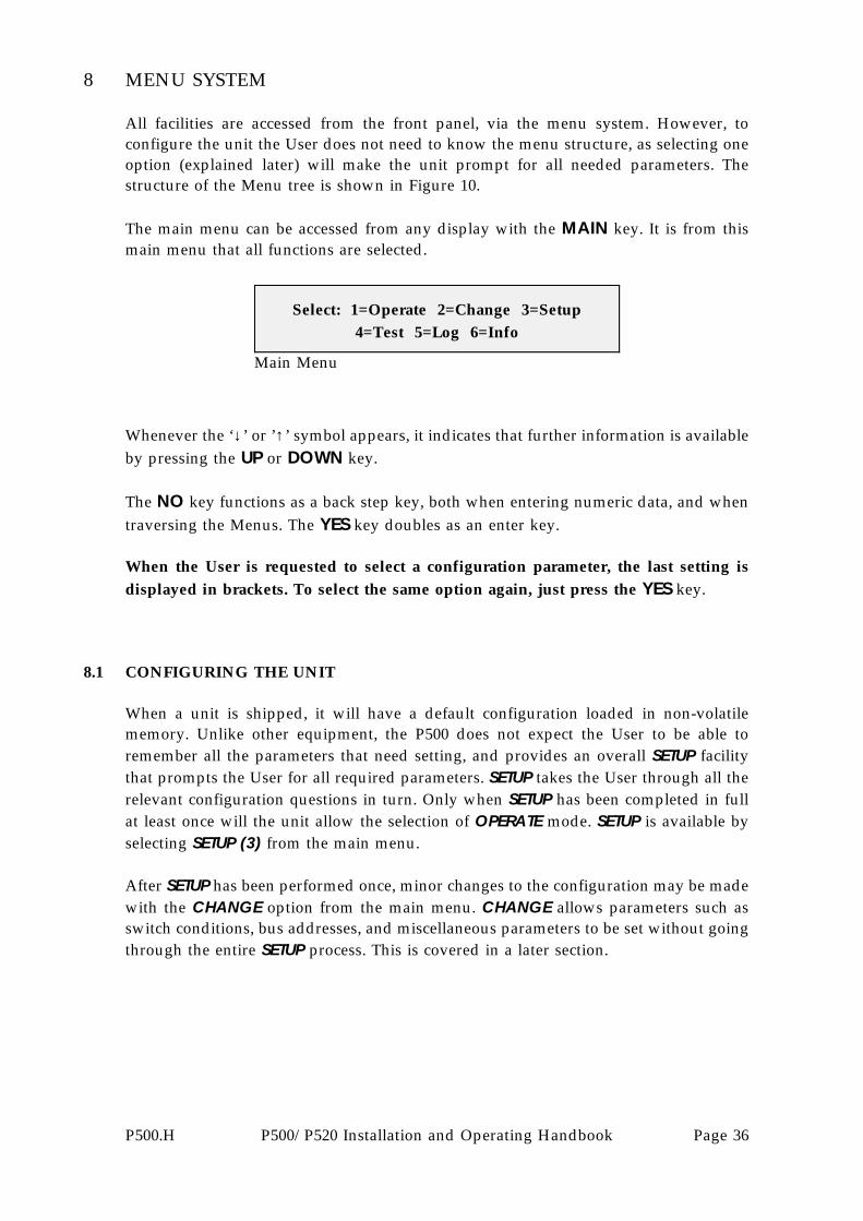
All facilities are accessed from the front panel, via the menu system. However, toconfigure the unit the User does not need to know the menu structure, as selecting oneoption (explained later) will make the unit prompt for all needed parameters. Thestructure of the Menu tree is shown in Figure 10.
The main menu can be accessed from any display with the MAIN key. It is from thismain menu that all functions are selected.
Main Menu
Select: 1=Operate 2=Change 3=Setup4=Test 5=Log 6=Info
Whenever the ‘↓’ or ’↑’ symbol appears, it indicates that further information is availableby pressing the UP or DOWN key.
The NO key functions as a back step key, both when entering numeric data, and whentraversing the Menus. The YES key doubles as an enter key.
When the User is requested to select a configuration parameter, the last setting isdisplayed in brackets. To select the same option again, just press the YES key.
8.1 CONFIGURING THE UNIT
When a unit is shipped, it will have a default configuration loaded in non-volatilememory. Unlike other equipment, the P500 does not expect the User to be able toremember all the parameters that need setting, and provides an overall SETUP facilitythat prompts the User for all required parameters. SETUP takes the User through all therelevant configuration questions in turn. Only when SETUP has been completed in fullat least once will the unit allow the selection of OPERATE mode. SETUP is available byselecting SETUP (3) from the main menu.
After SETUP has been performed once, minor changes to the configuration may be madewith the CHANGE option from the main menu. CHANGE allows parameters such asswitch conditions, bus addresses, and miscellaneous parameters to be set without goingthrough the entire SETUP process. This is covered in a later section.
P500.H P500/P520 Installation and Operating Handbook Page 36

SELECT OPTIONS1. AUDIBLE ALARM
3. ENABLE/DISABLE AUTO MODE (EVERY 24 HOURS)
LOCKOUTS BACKUP IN SERVICE (1)MODE: AUTO FAULT, TRAFFIC MODEM 1
OPERATE:
1. SYSTEM CONFIG2. DEFINE FAULTS3. BACKUP PARAMETERS
8. REAL TIME CLOCK
CHANGE:
INFO:
1. VIEW CONFIG2. PRINT CONFIG3. INFO ON THIS UNIT
PRINT:
1. UNPRINTED ENTRIES2. WHOLE LOG3. CANCEL
LOG:
1. CLEAR2. VIEW - SCROLL THROUGH LOG ENTRIES3. PRINT
TEST:
2. PSU MONITORING
MAIN MENU
1. OPERATE2. CHANGE3. SETUP GO THROUGH ALL4. TEST CHANGE OPTIONS5. LOG6. INFO
SYSTEM:1. NUMBER OF TRAFFIC
MODEMS IN SYSTEM2. RS485 BUS ADRESSES
FOR EACH MODEM
DEFINE FAULTS (FOR EACH MODEM):1. UNIT FAULT ONLY2. RX TRAFFIC FAULT OR UNIT FAULT3. TX TRAFFIC FAULT OR UNIT FAULT4. ANY FAULT (EXCEPT DEFERRED)
BACKUP PARAMETERS:
3. SWITCH BACK TO TRAFFIC MODEM IF FAULT CLEARS?
CLOCK:
5. LOCKOUT (DON’T SWITCH)
4. MANUAL/AUTO MODE5. FORCE BACKUP/BRIDGE
DISPLAY CURRENT TIME; EDIT IF NECESSARY
1. LED TEST
7. ALARM OPTIONS
ALARM OPTIONS:
2. SUMMARY ALARM RELAYS
MANUAL/AUTO:1. MANUAL CONTROL2. FULL AUTOMATIC REDUNDANCY SWITCHING
FORCE BACKUP/BRIDGE:
1. MANUAL BACKUP WHICH TRAFFIC MODEM? 2. MANUAL BRIDGE WHICH TRAFFIC MODEM?
MODEMS CURRENTLY LOCKED OUT:
3,4,6,8
2. WAIT FOR FAULTS TO CLEAR
TRAFFIC MODEM 1: UNIT FAULTFAULTS ALSO ON 2,5,7 BACKUP OK
LOCKOUTS:
FAULTS:
HOW MANY TIMES?
6. LEARN
LEARN:
1. LEARN ALL MODEM CONFIGURATIONS
2. LEARN SELECTED MODEM CONFIG WHICH?
WAIT HOW LONG?
LOCKOUTS BACKUP OK, BRIDGING 4 MODE: AUTO ALL TRAFFIC MODEMS OK
OPERATE:
MODEMS CURRENTLY LOCKED OUT:
NONE
ALL TRAFFIC MODEMS OKBACKUP MODEM OK
LOCKOUTS:
FAULTS:
LOCKOUTS BACKUP IN SERVICE (4) MODE: MANUAL ALL TRAFFIC MODEMS OK
OPERATE:
MODEMS CURRENTLY LOCKED OUT:3,4,6,8
LOCKOUTS:
FAULTS:
LOCKOUTS BACKUP MODEM FAULT MODE: AUTO ALL TRAFFIC MODEMS OK
OPERATE:
MODEMS CURRENTLY LOCKED OUT:NONE
ALL TRAFFIC MODEMS OKBACKUP MODEM UNIT FAULT
LOCKOUTS:
FAULTS:
ALL TRAFFIC MODEMS OKBACKUP MODEM OK
FIGURE 11 - P500 MENU STRUCTURE
EXAMPLE: EXAMPLE:
EXAMPLE: EXAMPLE:
SELECT OPTIONS
P500B8.CDR(EPS)
3. MODEM COMMS TEST
1. HOLDOFF TIME
P500.H P500/P520 Installation and Operating Handbook Page 37

8.2 OPERATION
Selecting OPERATE (1) from the main menu will display the following screen:
Operate Screen
Mode:AUTO Fault, Traffic Modem 1 ↑Lockouts↓ Backup in service (1)
At the top left of the screen the Operating Mode is shown as AUTO which indicates thatthe P500 requires no Operator intervention to perform a backup. MANUAL would bedisplayed here if the P500 was under Operator control.
To the right of this is a status message concerning Traffic Modem 1, and an up arrow(↑), indicating that if the User presses the up arrow, more information can be obtained.This is covered in a section immediately below.
At the bottom left is the word Lockouts ↓. Pressing the down arrow will show the Userthe Traffic Modems which are currently ’locked out’, which means that they have beendeliberately removed from the redundancy system, so that even in the event of a failureon that Traffic Modem, the Backup Modem will not switch in to take its place.
At the bottom right is a status message concerning the Backup Modem. In this case it isin service, and the number in parentheses indicates the number of the Traffic Modem itis backing up.
Pressing the up arrow (↑) displays the faults screen:
Faults Screen
Traffic Modem 1: Unit FaultBackup Modem OK ↓
Pressing the down arrow (↓) from the Operate Screen displays the lockouts screen:
Lockouts Screen
Modems currently locked out:3,4,6,8 ↑
In each of the preceding two screens, pressing the arrow displayed will return theUser to the main OPERATE screen.
Figure 10 shows four examples of Operate displays under various conditions.
P500.H P500/P520 Installation and Operating Handbook Page 38

8.3 CHANGE
Selecting CHANGE (2) from the main menu will display the following screen:
Change Menu
1=Config 2=Define faults 3=Backup params4=Mode 5=Force 6=Learn 7=Alarm 8=Clock
The following options are displayed:
Config (1) This takes the User to sub-menus to define the number ofModems in the system and their RS485 bus addresses.
Define faults (2) This takes the User to a sub-menu which permits the User todefine the fault conditions, for each Modem, which will causea backup.
Backup params (3) Selecting this choice will take the User to the Backupconfiguration sub-menus, which permit the User to defineparameters such as holdoff time, whether to switch back iffaults clear on a Traffic Modem, and how long to wait for thefaults to clear.
Mode (4) This choice takes the User to a sub-menu which permits thechoice of Manual or Automatic mode. Manual, as it nameimplies, permits the User to force bridging and backups tooccur via commands from the front panel, and will take placeirrespective of the fault state of the Modems in the system. InAutomatic, backups occur based on the Backup Parameters (3).
Force (5) If the unit is Manual mode, using this sub-menu, the User candefine which unit is being bridged, and may, if desired, forcea Backup Modem on-line.
Learn (6) This choice permits the P500 to learn all, or a selectedModem’s configuration, so that in the event of a failure, theBackup Modem can be re-programmed to match the failedunit. The option is also provided to permit the P500 tointerrogate all modems every 24 hours, in case a User haschanged a Modem’s configuration, but has not gone throughthe P500 ’Learn’ cycle.
Alarm (7) This sub-menu allows the User to define the way in which theaudible alarm and alarm relays respond to system events.
Clock (8) This permits the User to view, and if necessary, edit, the timeand date set by the internal real-time clock.
P500.H P500/P520 Installation and Operating Handbook Page 39

These options will now be described in more detail.
Selecting CHANGE (2) CONFIG (1) displays the following screen:
Modem Configuration Screen
1=Set number of Modems in system2=Set RS485 bus addresses
If the User selects 1=Set number of Modems in system, the following screen isdisplayed:
Number of Modems in System Screen
Is this a 1:8 system?(Yes)/(No)
The P500 can determine the number of TIMs plugged into the system. If, forinstance there are 8 TIMs present, the P500 will assume that this is a 1:8 system.If, however, there are only 5 (out of 8) active TIMs in use, with 5 Traffic Modems,the User should answer ’No’ to the question, and the User will then be promptedto enter the number of active TIMs. This is important, as it will cause the frontpanel System Summary Display not to display any information concerninginactive TIMs.
IMPORTANT NOTE:
Looking at the rear of the P520, the first TIM on the LEFT-HAND SIDE is definedas Unit 1, with TIMs 2 - 7 in ascending order to the right. Users should usecontiguously numbered TIM slots in systems with less than 8 Traffic modems,always starting from position 1.
For example, if the User has a system with 5 Traffic Modems, he should useTIMs 1 through 5, and define the system as having 5 Modems present, using theconfiguration screen.
If the User selects 2=Set RS485 bus addresses, the following screen is displayed:
RS485 Bus Addresses Screen
Change the address of which Modem?(0-8) (0=Backup) (Yes when finished)
The User enters the number of the Modem (the backup is defined as Unit 0) andthen enters a valid, unique bus address in the range 1-255.
P500.H P500/P520 Installation and Operating Handbook Page 40

IMPORTANT NOTE: The bus address entered here must match the address seton the corresponding Modem in the system! If this is not done, the P500 will beunable to communicate with the Modem, and will therefore not functioncorrectly.
If the system is being monitored and controlled by the Paradise Datacom Multi-Unit Software, the address range of any Modem in the system must lie in therange 1-99. The P500 will warn the User if an address has been duplicated, andwill prompt the User to re-enter a valid (and unique) bus address.
Selecting CHANGE (2) DEFINE FAULTS (2) displays the following screen:
Define Faults Screen
Define faults causing backup forwhich unit? (1-8) (Yes when finished)
This sub-menu prompts the User to enter a Modem number, so that the conditionsunder which the P500 will perform a backup can be defined. Once a valid Modemnumber has been entered, the following sub-menu is displayed:
Define Faults Sub-Menu
Modem 1, backup after: (5) 1=Unit fault2=Rx 3=Tx 4=Any 5=Lockout
Selecting 1=Unit Fault defines that a backup will only occur if a Traffic Modemexhibits a UNIT FAULT. A Unit fault is defined as a hardware related problemwithin a Modem, such as an internal power supply fault, loss of IF synthesizerlock, etc.
Selecting 2=Rx defines that a backup will only occur if there is a RECEIVETRAFFIC FAULT, such as loss of Demod Lock, loss of Frame Sync, etc, OR aUnit Fault.
Selecting 3=Tx defines that a backup will only occur if there is a TRANSMITTRAFFIC FAULT, such as Loss of Clock from Terrestrial, etc, OR a Unit Fault.
Selecting 4=Any defines that a backup will occur if there is a UNIT FAULT , aRECEIVE TRAFFIC FAULT, or a TRANSMIT TRAFFIC FAULT. Note thatDeferred Alarms (e.g. a Backward Alarm) do not cause a backup to occur.
Selecting 5=Lockout defines that the Modem is effectively removed from theredundancy switching system, and no backup will occur even if faults arepresent. Note that in the OPERATE screen, pressing the down arrow ↓ willdisplay all of the Modems currently defined as locked out.
P500.H P500/P520 Installation and Operating Handbook Page 41
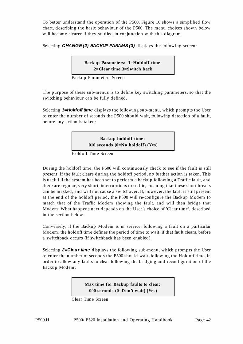
To better understand the operation of the P500, Figure 10 shows a simplified flowchart, describing the basic behaviour of the P500. The menu choices shown belowwill become clearer if they studied in conjunction with this diagram.
Selecting CHANGE (2) BACKUP PARAMS (3) displays the following screen:
Backup Parameters Screen
Backup Parameters: 1=Holdoff time2=Clear time 3=Switch back
The purpose of these sub-menus is to define key switching parameters, so that theswitching behaviour can be fully defined.
Selecting 1=Holdoff time displays the following sub-menu, which prompts the Userto enter the number of seconds the P500 should wait, following detection of a fault,before any action is taken:
Holdoff Time Screen
Backup holdoff time:010 seconds (0=No holdoff) (Yes)
During the holdoff time, the P500 will continuously check to see if the fault is stillpresent. If the fault clears during the holdoff period, no further action is taken. Thisis useful if the system has been set to perform a backup following a Traffic fault, andthere are regular, very short, interruptions to traffic, meaning that these short breakscan be masked, and will not cause a switchover. If, however, the fault is still presentat the end of the holdoff period, the P500 will re-configure the Backup Modem tomatch that of the Traffic Modem showing the fault, and will then bridge thatModem. What happens next depends on the User’s choice of ’Clear time’, describedin the section below.
Conversely, if the Backup Modem is in service, following a fault on a particularModem, the holdoff time defines the period of time to wait, if that fault clears, beforea switchback occurs (if switchback has been enabled).
Selecting 2=Clear time displays the following sub-menu, which prompts the Userto enter the number of seconds the P500 should wait, following the Holdoff time, inorder to allow any faults to clear following the bridging and reconfiguration of theBackup Modem:
Clear Time Screen
Max time for Backup faults to clear:000 seconds (0=Don’t wait) (Yes)
P500.H P500/P520 Installation and Operating Handbook Page 42

Y
N
Y
N
N
Y
N
Y
N
Y
Y
N
N
Y
Y
N
Y
N
Y
N
N
Y
CHANGE IN STATE OCCURS
SWITCH BACKTO TRAFFIC
MODEM
SWITCHBACKUP INTO
SERVICE
SCAN FORCHANGE IN
ALARM STATE
MODEMGONE FROM
GOOD TO FAIL?
HAS
IS MODEMLOCKED
OUT?
IS FAULTDEFINED FOR
BACKUP?
WAIT FORHOLDOFF
TIME
FAULT STILLPRESENT?
CONFIGURE BACKUPINITIATE BRIDGE
IS CLEAR TIME SET TO ZERO?
START’CLEAR’ TIMER
FAULTSCLEARED ON
BACKUP?
HAVE
HAS TIMEREXPIRED?
FAULTS CLEARED ON
TRAFFIC MODEM?
MODEMCURRENTLY
BACKED UP?
IS
SYSTEM CONFIGUREDFOR SWITCH
BACK?
IS
MAINTAINBACKUP
INCREMENTSWITCHBACK
COUNTER
COUNT
MAXSWITCHBACK
EXCEEDED?
LOCK MODEMOUT, GENERATEPROMPT ALARM
FIGURE 12
P500 SIMPLIFIED
FLOW CHART
BEHAVIOURAL
P500B9.CDR(EPS)
WAIT FORHOLDOFF
TIME
FAULT STILLCLEARED?
Y
N
P500.H P500/P520 Installation and Operating Handbook Page 43

(IMPORTANT NOTE: The P500 will only consider Faults on the Backup Modemwhich have been defined as causing a backup for the particular Traffic Modem inquestion. For example, if a Traffic Modem has been defined for backup following anRx Prompt Alarm (or Unit Fault), then the Backup Modem will deem that faults havecleared when there is no Rx Prompt or Unit Fault detected on the Backup Modem.This means that the Backup will be switched into service even if there is a TXPrompt Alarm present.)
If the User enters a value of zero here, the P500 will switch the Backup into servicewith no further delay. If any other value is entered here, the P500 will wait untileither:
a) All defined faults clear on the Backup Modemb) The time period entered by the User expires;
whichever is sooner.
If the defined faults clear on the Backup Modem, then the P500 will immediatelyswitch the Backup Modem into service. If, however, following the period entered,there are still defined faults present, the backup will be abandoned, and no switchingwill occur. A ’backup failed’ message will appear on the Operate screen, which canthen be cleared with the ’YES’ key.
Selecting 3=Switch back displays the following sub-menu, which prompts the Userto define whether or not the P500 should return a previously failed Traffic Modemto service if the fault which caused a backup subsequently clears.
Switch Back Menu
Switch back to Traffic Modem if faultclears? (1) 0=No switch 1= Switch
If the User enters 1=Switch the following sub-menu is displayed, which furtherprompts the User to enter the number of times a switchback is allowed to occur(in a 24 hour period) before a Prompt Alarm is generated and that Modem islocked out:
Switch Back (Number of Times) Menu
Max no. of switchbacks in 24 hoursbefore lockout? 05 (0=Infinite) (Yes)
Selecting 0=No Switch defines that once the Backup has been switched into service,it will remain there until the Operator intervenes.
P500.H P500/P520 Installation and Operating Handbook Page 44
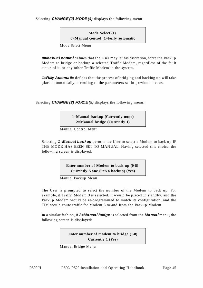
Selecting CHANGE (2) MODE (4) displays the following menu:
Mode Select Menu
Mode Select (1)0=Manual control 1=Fully automatic
0=Manual control defines that the User may, at his discretion, force the BackupModem to bridge or backup a selected Traffic Modem, regardless of the faultstatus of it, or any other Traffic Modem in the system.
1=Fully Automatic defines that the process of bridging and backing up will takeplace automatically, according to the parameters set in previous menus.
Selecting CHANGE (2) FORCE (5) displays the following menu:
Manual Control Menu
1=Manual backup (Currently none)2=Manual bridge (Currently 1)
Selecting 1=Manual backup permits the User to select a Modem to back up IFTHE MODE HAS BEEN SET TO MANUAL. Having selected this choice, thefollowing screen is displayed:
Manual Backup Menu
Enter number of Modem to back up (0-8)Currently None (0=No backup) (Yes)
The User is prompted to select the number of the Modem to back up. Forexample, if Traffic Modem 3 is selected, it would be placed in standby, and theBackup Modem would be re-programmed to match its configuration, and theTIM would route traffic for Modem 3 to and from the Backup Modem.
In a similar fashion, if 2=Manual bridge is selected from the Manual menu, thefollowing screen is displayed:
Manual Bridge Menu
Enter number of modem to bridge (1-8)Currently 1 (Yes)
P500.H P500/P520 Installation and Operating Handbook Page 45

The User is prompted to select the number of the Modem to bridge. For example,if Traffic Modem 4 is selected, the Backup Modem would be re-programmed tomatch its configuration, and the TIM would bridge Tx traffic for Modem 4 andsend a copy of the Tx clock and data to the Backup Modem.
Turning now to CHANGE (2) LEARN (6), it is vitally important that if the P500 is towork correctly, it must store the configurations of all Modems in the system. It learnsthese configurations by communicating with the Modem of interest, via the RS485bus. This data is then stored in non-volatile memory (NVRAM) within the P500, forlater use to program the Backup Modem. Selecting CHANGE (2) LEARN (6) displaysthe following menu:
Learn Configurations Menu
1=Learn all Modem configurations2=Learn specific 3=Auto learn
Selecting 1=Learn all modem configurations will display the following screen:
Learn All Modem Configurations Menu
Learn all Modem configurations:(Yes) to continue or (No) to cancel
Entering ’YES’ at this prompt will force the P500 to take control of the RS485M&C bus, and interrogate all Modems for their configuration. Users should notethat if an external computer is being used, with Paradise Datacom M&C software,there will be a momentary interruption to the main M&C bus, which could resultin ’NO COMMS’ messages on one or more units. In ’Learn all’ mode, theinterruption should last no more than a few seconds.
If, during this process, the P500 cannot successfully establish communications viathe RS485 bus, an alarm is generated.
Selecting 2=Learn specific will display the following screen:
Learn Specific Configuration Menu
Learn specific configuration (1-8)0 (Yes)
Entering a Modem number followed by ’YES’ at this prompt will force the P500to take control of the RS485 M&C bus, and interrogate the specific Modem for itsconfiguration. THIS SHOULD BE DONE EVERY TIME THE USERCHANGES THE CONFIGURATION OF A TRAFFIC MODEM!
P500.H P500/P520 Installation and Operating Handbook Page 46

Selecting 3=Auto learn will display the following screen:
Auto Learn Menu
Auto learn every 24 hours (1)0=Disable 1=Enable
Selecting 1=Enable defines that every 24 hours (at Midnight), without anyOperator intervention, the P500 will automatically take control of the RS485 bus,and re-learn all the modem configurations. This ensures that if an Operatorchanges the configuration of a Modem, but then forgets to update the P500accordingly, then within a 24 hour period, the new configuration will beautomatically read and stored.
The P500 is equipped with an audible alarm sounder, a high output type, andsummary alarm relays (Form ’C’ types) which are used to draw an Operator’sattention to changes of state in the system. Selecting CHANGE (2) ALARM (7)displays the following menu:
Alarm Options Menu
Alarm options1=Audible alarm 2=Summary alarm relays
Entering 1=Audible alarm will take the User to the following sub-menu:
Audible Alarm Menu
Audible alarm (0)0=Disable 1=Unit/prompt 2=Unit
Entering 0=Disable defines that the audible alarm is turned off all the time.Entering 1=Unit/prompt defines that the audible alarm will sound when a UnitFault or Prompt Alarm (Rx or Tx) occurs on any Modem, or the P500 itself.Entering 2=Unit defines that the audible alarm will sound only when a Unit Faultoccurs on any Modem, or the P500 itself.
The Audible Alarm can be cleared (acknowledged) by pressing the YES key. Thealarm will be re-activated following the next change of state (to a fault condition)which occurs in the system. Alternatively, the Audible alarm can be silenced byusing an external contact closure, applied to the correct pins of either the Aux 1or Aux 2 connectors at the rear of the P520. See Appendix A for pin details.
NOTE THAT WHEN THE ALARM SOUNDER HAS BEEN SELECTED, IT WILLONLY BE ACTIVE IN THE OPERATE, FAULTS OR LOCKOUT SCREENS.
P500.H P500/P520 Installation and Operating Handbook Page 47

Entering 2=Summary alarm relays takes the User to the following sub-menu:
Summary Alarm Relays Menu
Summary alarm relays (3) 1=True status2=New, Ack clears 3=Change, Ack clears
This sub-menu permits the User to define exactly how the Alarm relay closures,found on the connector at the rear of the P500, will respond to various events inthe system.
1=True Status means that, if selected, the relays will reflect the true status of thesystem at all times. The relays cannot be cleared down by any sort ofacknowledgement.
2=New, Ack clears means that, if selected, the relays will activate following achange in state from good to a fault condition. Furthermore, the relays can becleared down (reset) by pressing the YES key to acknowledge, or by use of anexternal acknowledge contact closure on Aux 1 or Aux 2.
By way of an example, suppose that a RX Traffic Fault has occurred on aModem. The Rx Summary Alarm relay will activate, and bring the fault to theattention of the Operator. The Operator acknowledges the alarm, and the relayis consequently reset. The relay will stay reset until the next occurrence of a newfault condition.
3=Change, Ack clears means that, if selected, the relays will activate followingany change in state. The relays can be cleared down (reset) by pressing the YESkey to acknowledge, or by use of an external acknowledge contact closure onAux 1 or Aux 2.
In contrast to the example cited above, suppose also that a RX Traffic Fault hasoccurred on a Modem. The Rx Summary Alarm relay will activate, and bring thefault to the attention of the Operator. The Operator acknowledges the alarm, andthe relay is consequently reset. If the fault now clears, the relay will now re-activate, again alerting the attention of the Operator. The relay will remain setuntil the Operator acknowledges it.
P500.H P500/P520 Installation and Operating Handbook Page 48

The P500 is also equipped with an internal real-time clock, which is used to time anddate stamp events which are recorded in the P500’s log. Selecting CHANGE (2)CLOCK (8) displays the following menu:
Real-Time Clock Menu
Now: 12:23:02 01 Aug 1995 OK? (Yes)1=Time adjust 2=Date adjust
Selecting 1=Time adjust takes the User to the following screen:
Time Adjust Menu
Time adjust (hh:mm:ss): : (Yes)
The user can then enter the new time value in the form hours:minutes:seconds, thenpress YES to accept the new value.
Selecting 2=Date adjust takes the User to the following screen, where the date isentered in day/month/year format:
Date Adjust Menu
Date adjust (dd/mm/yy)/ / (Yes)
P500.H P500/P520 Installation and Operating Handbook Page 49
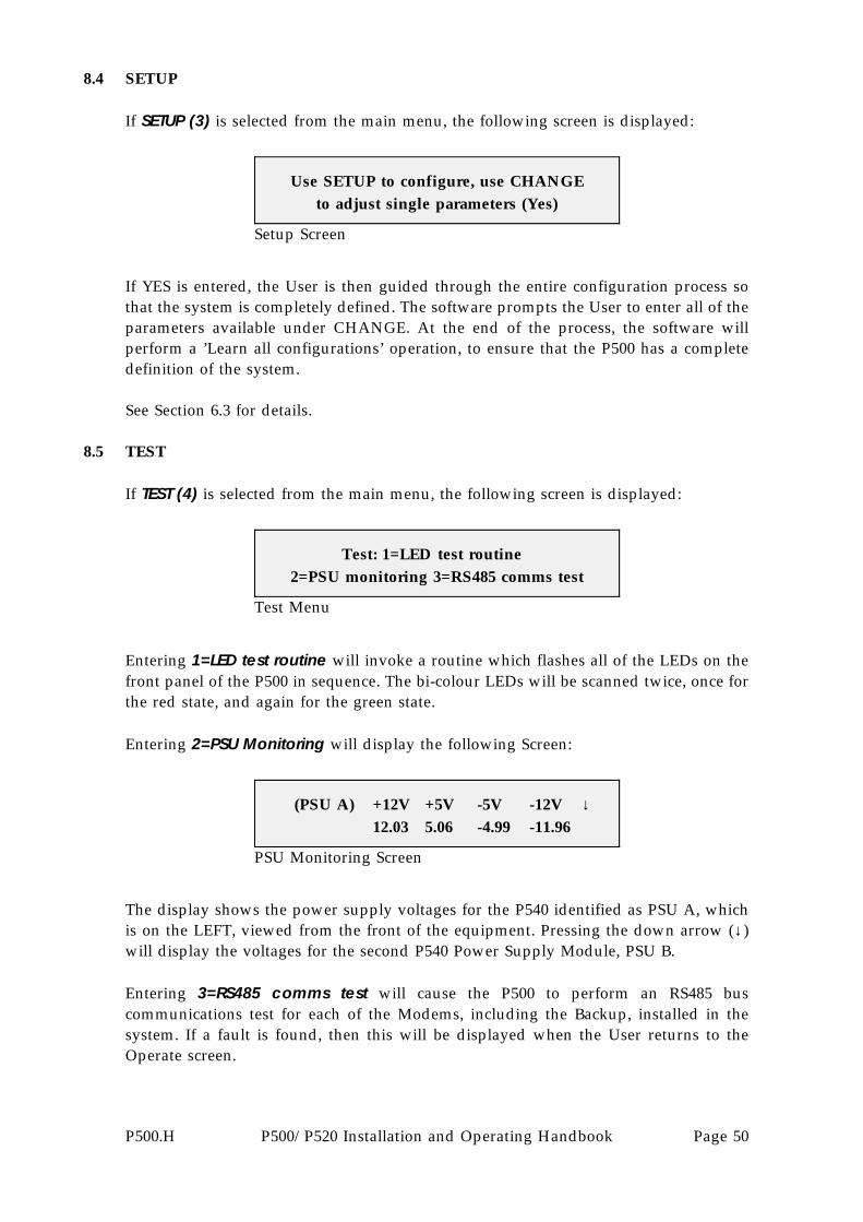
8.4 SETUP
If SETUP (3) is selected from the main menu, the following screen is displayed:
Setup Screen
Use SETUP to configure, use CHANGEto adjust single parameters (Yes)
If YES is entered, the User is then guided through the entire configuration process sothat the system is completely defined. The software prompts the User to enter all of theparameters available under CHANGE. At the end of the process, the software willperform a ’Learn all configurations’ operation, to ensure that the P500 has a completedefinition of the system.
See Section 6.3 for details.
8.5 TEST
If TEST (4) is selected from the main menu, the following screen is displayed:
Test Menu
Test: 1=LED test routine2=PSU monitoring 3=RS485 comms test
Entering 1=LED test routine will invoke a routine which flashes all of the LEDs on thefront panel of the P500 in sequence. The bi-colour LEDs will be scanned twice, once forthe red state, and again for the green state.
Entering 2=PSU Monitoring will display the following Screen:
PSU Monitoring Screen
(PSU A) +12V +5V -5V -12V ↓12.03 5.06 -4.99 -11.96
The display shows the power supply voltages for the P540 identified as PSU A, whichis on the LEFT, viewed from the front of the equipment. Pressing the down arrow (↓)will display the voltages for the second P540 Power Supply Module, PSU B.
Entering 3=RS485 comms test will cause the P500 to perform an RS485 buscommunications test for each of the Modems, including the Backup, installed in thesystem. If a fault is found, then this will be displayed when the User returns to theOperate screen.
P500.H P500/P520 Installation and Operating Handbook Page 50

8.6 LOG
If LOG (5) is selected from the main menu, the following screen is displayed:
Log Menu
Event Log (43 entries)1: Clear 2: View 3: Print
See Section 9 for more details.
8.7 INFORMATION
If INFO (6) is selected from the main menu, the following menu is displayed:
Information Screen
Info: 1=View config2=Print config 3=This Unit
If 1=View config is selected, the User is presented with a summary of informationconcerning the present configuration, such as number of Modems defined in the system,Mode, default Modem to bridge, etc, etc.
If 2=Print config is selected, the same information displayed above is output to a printeror PC, via the front panel Monitor Port.
If 3=This unit is selected, information is displayed on the serial number, equipment type,and internal Software version of the P500.
P500.H P500/P520 Installation and Operating Handbook Page 51

9 LOG
9.1 GENERAL
The traffic log records the last 500 events which affect the transmit or receive traffic. Thetime and date each event is also recorded. The log can either be viewed on the LCD, orprinted on a serial printer attached to the front panel port.
Selecting LOG (5) displays the following menu:
Log Menu
Event Log (137 entries):1: Clear 2: View 3: Print
The number in parentheses on the top line is the event count. It indicates the currentnumber of events stored in the log. When this number reaches 500, further events arestill added to the log by overwriting the oldest event, so that the log stores the latest 500events. If a record of all traffic events is required, then a hard copy of the log should bemade before the event count reaches 500.
9.2 HARD COPY
There are several methods to make a hard copy, all of which require a serial printer tobe attached to the front panel port of the equipment (lead available, see later). Serial datais at 9600 Baud, RS232 levels, 8 data bits, no parity, one stop bit. There are no options.The printer carriage is also assumed to be 80 columns wide.
Selecting PRINT (3) from the above menu displays the following screen:
Print Log Menu
Log Print: 1=Whole log (137 entries)2=Unprinted entries (32) 3=Cancel
The unit keeps a record of the last log printout, and can therefore print all the eventsin the log, or just events added since the last hard copy. This provides a simplemechanism to make a hard copy of all events on the traffic circuit, without havingto manually clear the log at the end of each printout. As soon as option 1 or 2 isselected, printing begins. To terminate printing, access this menu again and selectCANCEL (3).
The front panel port of the P500/P520 allows the printing of the log to be started bygrounding one of two pins on this front panel connector. The P1390 lead (see later)available from Paradise has two toggle switches connected to these pins allowing a
P500.H P500/P520 Installation and Operating Handbook Page 52
log printout to be initiated without operating the front panel of the equipment (thatcan be locked). The two switches provide the following functions:
Print Log This is functionally equivalent to selecting Log, Print unprintedentries as described above. This alternative method of printing thelog has the advantage that a printer may be plugged sequentiallyinto many units in turn, and a daily/weekly hard copy of all newtraffic events made.
Live Print This enables printing of events as they are added to the log, andis only of any use while a printer is attached to the front panelport. It is useful during initial circuit operation, providing animmediate hard copy of any events that occur. It also guaranteesthat ALL events will be printed if more than 500 events occur atany one time, as no logged event is overwritten before it can beprinted.
9.3 PRINTER LEAD
The P1390 lead, available from Paradise Datacom, allows the P500/P520 to be connectedto the serial port of a Personal Computer. The PC should be set up to emulate a dumbterminal (or a printer). The PC can then capture the log printout onto disk as apermanent record, or act as an interface between the serial port and a parallel printer.
P500.H P500/P520 Installation and Operating Handbook Page 53
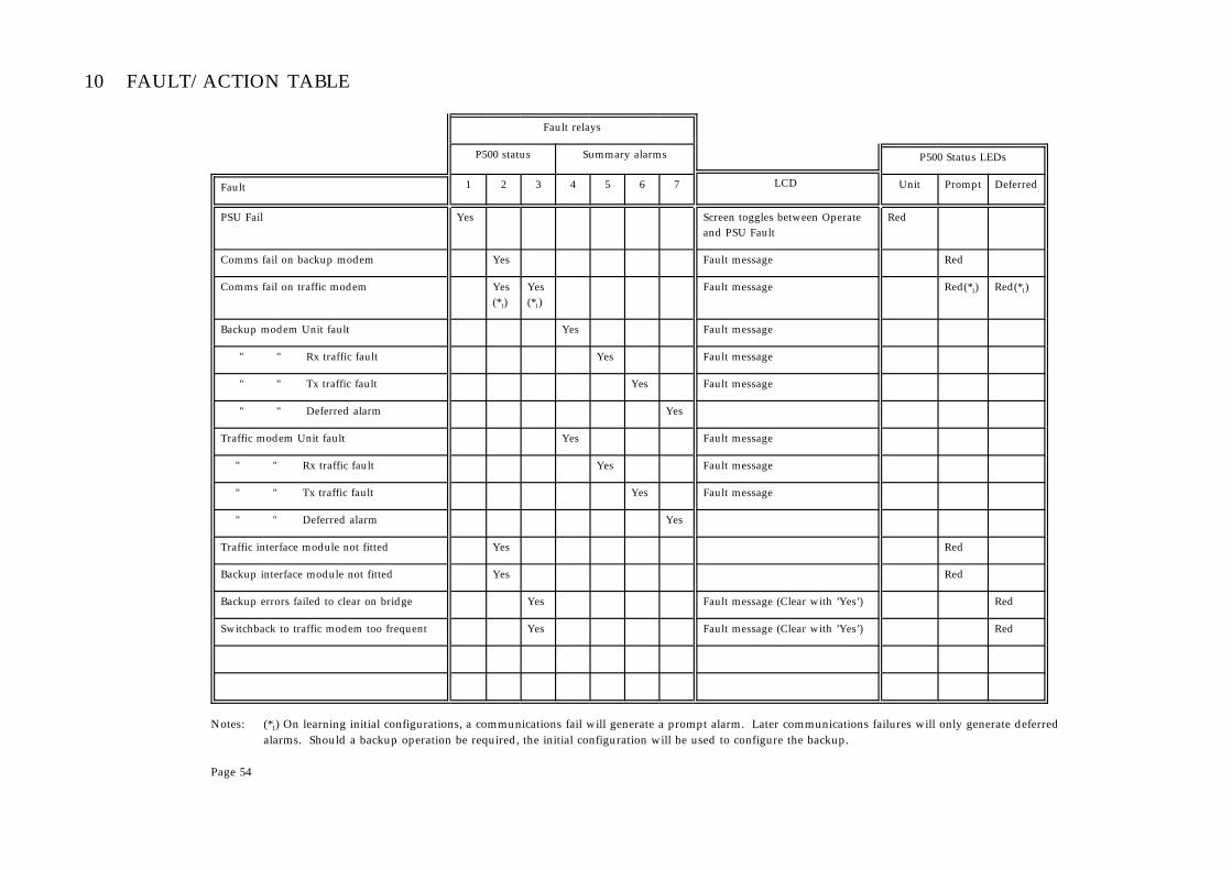
10 FAULT/ACTION TABLE
Fault relays
P500 status Summary alarms P500 Status LEDs
Fault 1 2 3 4 5 6 7 LCD Unit Prompt Deferred
PSU Fail Yes Screen toggles between Operateand PSU Fault
Red
Comms fail on backup modem Yes Fault message Red
Comms fail on traffic modem Yes(*1)
Yes(*1)
Fault message Red(*1) Red(*1)
Backup modem Unit fault Yes Fault message
" " Rx traffic fault Yes Fault message
" " Tx traffic fault Yes Fault message
" " Deferred alarm Yes
Traffic modem Unit fault Yes Fault message
" " Rx traffic fault Yes Fault message
" " Tx traffic fault Yes Fault message
" " Deferred alarm Yes
Traffic interface module not fitted Yes Red
Backup interface module not fitted Yes Red
Backup errors failed to clear on bridge Yes Fault message (Clear with ’Yes’) Red
Switchback to traffic modem too frequent Yes Fault message (Clear with ’Yes’) Red
Notes: (*1) On learning initial configurations, a communications fail will generate a prompt alarm. Later communications failures will only generate deferredalarms. Should a backup operation be required, the initial configuration will be used to configure the backup.
Page 54

APPENDIX A: P500/P520 CONNECTOR PINOUTS
P520 System Alarms - 15 pin male ’D’ type connector
Important Note: (N/O means ’normally open’ in the non-fail state)(N/C means ’normally closed’ in the non-fail state)
Description N/O N/C
Summary Unit fault 4 12
Summary Tx Traffic fault 6 14
Summary Rx Traffic fault 5 13
Summary Deferred Alarm 7 15
Switch Unit Fault 1 9
Switch Prompt Alarm 2 10
Switch Deferred Alarm 3 11
Relay Common 8
All relay contacts rated 30V DC 2A, or 125V AC 0.4A.
P520 RS485 In - 9 pin Female ’D’ Type connector
Description Pin No. Direction
In A 1 Data from M&C Computer to Modems, via P500
In B 6 Data from M&C Computer to Modems, via P500
Out A 2 Data from Modems to M&C Computer, via P500
Out B 7 Data from Modems to M&C Computer, via P500
Ground 5 Signal ground
P520 RS485 Out - 9 pin Male ’D’ Type connector
Description Pin No. Direction
In A 2 Data from Modems to P500
In B 7 Data from Modems to P500
Out A 1 Data from the P500 to Modems
Out B 6 Data from the P500 to Modems
Ground 5 Signal ground
P500.H P500/P520 Installation and Operating Handbook Page 55

P520 Auxiliary 1 - 15 pin Female ’D’ Type connector
Signal Description Pin No. Comment
Ground 2,3,4
Fused 5 volt 1,9
Fused 12 volt 10
External Ack’ Input 11 (Requires TTL low, or contact to Gnd)
Modem Address 0 12 (Open Collector Output)
Modem Address 1 5 (Open Collector Output)
Modem Address 2 13 (Open Collector Output)
Backup/*Bridge 6 (Open Collector Output)
Control 5 (uncommitted) 14 (Open Collector Output)
Control 6 (uncommitted) 7 (Open Collector Output)
Control 7 (uncommitted) 15 (Open Collector Output)
Control 8 (uncommitted) 8 (Open Collector Output)
P520 Auxiliary 2 - 15 pin Female ’D’ Type connector
Transponder Switch Control (Not Aux 1 as described in earlier versions of this handbook)
Signal Description Pin No. Comment
Ground 2,3,4
Fused 5 volt 1,9
Fused 12 volt 10
External Ack’ Input 11 (Requires TTL low, orcontact to Gnd)
Backup in Service for Modem 1 12 (Open Collector Output)
Backup in Service for Modem 2 5 (Open Collector Output)
Backup in Service for Modem 3 13 (Open Collector Output)
Backup in Service for Modem 4 6 (Open Collector Output)
Backup in Service for Modem 5 14 (Open Collector Output)
Backup in Service for Modem 6 7 (Open Collector Output)
Backup in Service for Modem 7 15 (Open Collector Output)
Backup in Service for Modem 8 8 (Open Collector Output)
P500.H P500/P520 Installation and Operating Handbook Page 56

P500 Front Panel Connector - 8 pin DIN
Connector type: 8 pin DIN, latching female
Connection numbering from front: Clockwise from the top - 2,5,3,7,6,1,4, centre 8
Description Pin No.
Ground 2
Serial printer out (RS232) 4
Trigger printout of unprinted log entries 6
Enable printout of new log entries (Live) 7
The Serial printer port is at 9600 Baud, RS232 levels, 8 data bits, no parity, one stopbit. There are no options. Note that there is no handshaking on the printer port, noteven XON/XOFF, and the printer carriage is assumed to be 80 columns wide.
By grounding pin 6 on the connector, the P500/P520 is instructed to dump the trafficlog to the printer, but only events added since those last printed. By grounding pin7, the P500/P520 is instructed to print traffic events as they are added to the trafficlog.
To connect the serial printer port (DIN plug) to a standard PC serial port (’D’ typefemale), the following connections are required:
DIN pin 4 to ‘D’ pin 3DIN pin 5 to ‘D’ pin 2DIN pin 2 to ‘D’ pin 7
A standard test/printer lead is available from Paradise Datacom, part numberP1390. This lead provides the required connections to a 25 pin D type for the serialprinter.
P500.H P500/P520 Installation and Operating Handbook Page 57

APPENDIX B: P550 CONNECTOR PINOUTS - BIM
Modem Interface - Data/Control/ESC/Backward AlarmsConnector Type: 50 pin Male ’D’ type
Data Interface
Pin Signal Name RS422 V.35 X.21DCE
X.21DTE
G.703 E1 bal,64kbps,
& T1
G.703 E1unbal (75Ω)
To/FromModem
6 Tx Clock A TT A SCTE A - S A - - To
23 Tx Clock B TT B SCTE B - S B - - To
5 TX Data A SD A SD A T A R A TX A TX Data To
22 TX Data B SD B SD B T B R A TX B - To
3 RX Clock A RT A SCR A S A - - - From
20 RX Clock B RT B SCR B S B - - - From
1 RX Data A RD A RD A R A T A RX A RX Data From
18 RX Data B RD B RD B R B T B RX B - From
2 ETC A ST A SCT A - - - - From
19 ETC B ST B SCT B - - - - From
4 Rx Ready A RR A RLSD A I A C A - - From
21 Rx Ready B RR B RLSD B I B C A - - From
17 Signal Gnd SG SG ----------- Sig Gnd ------------ From/to
27 Prot. Gnd RC FG ------------ SHIELD ----------- From/to
Alarm Interface
Pin Description To/From
9 Unit Alarm N/C From
26 TX Traffic Alarm N/C From
25 RX Traffic Alarm N/C From
10 RX Traffic Alarm N/O From
8 Deferred Alarm N/C From
24 Interface Tri-State To
7 TX Carrier Inhibit To
IDR Audio ESC (Switching requires optional P552 Switching module fitted to TIM)See Note 1
Pin Signal Name Signal Type To/From
11 ESC Audio TX A + Voice, 600 Ω balanced To
12 ESC Audio TX A - Voice, 600 Ω balanced To
28 ESC Audio RX A + Voice, 600 Ω balanced From
29 ESC Audio RX A - Voice, 600 Ω balanced From
49 ESC Audio TX B + Voice, 600 Ω balanced To
48 ESC Audio TX B - Voice, 600 Ω balanced To
47 ESC Audio RX B + Voice, 600 Ω balanced From
46 ESC Audio RX B - Voice, 600 Ω balanced From
P500.H P500/P520 Installation and Operating Handbook Page 58
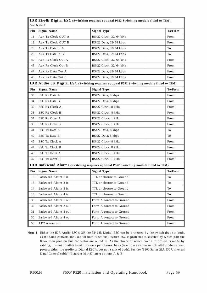
IDR 32/64k Digital ESC (Switching requires optional P552 Switching module fitted to TIM)See Note 1
Pin Signal Name Signal Type To/From
11 Aux Tx Clock OUT A RS422 Clock, 32/64 kHz From
12 Aux Tx Clock OUT B RS422 Data, 32/64 kbps From
28 Aux Tx Data In A RS422 Data, 32/64 kbps To
29 Aux Tx Data In B RS422 Data, 32/64 kbps To
49 Aux Rx Clock Out A RS422 Clock, 32/64 kHz From
48 Aux Rx Clock Out B RS422 Clock, 32/64 kHz From
47 Aux Rx Data Out A RS422 Data, 32/64 kbps From
46 Aux Rx Data Out B RS422 Data, 32/64 kbps From
IDR Audio 8K Digital ESC (Switching requires optional P552 Switching module fitted to TIM)
Pin Signal Name Signal Type To/From
35 ESC Rx Data A RS422 Data, 8 kbps From
34 ESC Rx Data B RS422 Data, 8 kbps From
39 ESC Rx Clock A RS422 Clock, 8 kHz From
38 ESC Rx Clock B RS422 Clock, 8 kHz From
37 ESC Rx Octet A RS422 Clock, 1 kHz From
36 ESC Rx Octet B RS422 Clock, 1 kHz From
41 ESC Tx Data A RS422 Data, 8 kbps To
40 ESC Tx Data B RS422 Data, 8 kbps To
45 ESC Tx Clock A RS422 Clock, 8 kHz From
44 ESC Tx Clock B RS422 Clock, 8 kHz From
43 ESC Tx Octet A RS422 Clock, 1 kHz From
42 ESC Tx Octet B RS422 Clock, 1 kHz From
IDR Backward Alarms (Switching requires optional P552 Switching module fitted to TIM)
Pin Signal Name Signal Type To/From
16 Backward Alarm 1 in TTL or closure to Ground To
15 Backward Alarm 2 in TTL or closure to Ground To
14 Backward Alarm 3 in TTL or closure to Ground To
13 Backward Alarm 4 in TTL or closure to Ground To
33 Backward Alarm 1 out Form A contact to Ground From
32 Backward Alarm 2 out Form A contact to Ground From
31 Backward Alarm 3 out Form A contact to Ground From
30 Backward Alarm 4 out Form A contact to Ground From
50 AD2 Alarm out Form A contact to Ground From
Note 1 Either the IDR Audio ESC’s OR the 32/64k Digital ESC can be protected by the switch (but not both,as the same contacts are used for both functions). Which ESC is protected is selected by which port the8 common pins on this connector are wired to. As the choice of which circuit to protect is made bycabling, it is not possible to mix this on a per channel basis (ie within any one switch, all 8 modems mustprotect either the Audio or Digital ESC’s, but not a mix of both). See the "P300 Series EIA 530 UniversalData/Control cable" (diagram M1487 later) options A & B
P500.H P500/P520 Installation and Operating Handbook Page 59

P550 BIM CONNECTOR PINOUTS - continued
Modem Alarms - 9 pin Male ‘D’ type connector
Important Note: (N/O means ’normally open’ in the non-fail state)(N/C means ’normally closed’ in the non-fail state)
Description N/O N/C
Unit fault 2 7
Tx Traffic fault (Tx Prompt) 4 9
Rx Traffic fault (Rx Prompt) 3 8
Deferred Alarm 1 6
Ground (common) 5
All relay contacts rated 30V DC 2A, or 125V AC 0.4A.
External Over-Ride Connector - 9 pin Female ’D’ type connector
Description Pin No. Direction
Ground 2,6
Over-ride input 5,9 (Requires TTL low or contact closure to Ground)
LED 1 output, anode 7 (Provides approx 10 mA current for an externalLED connected between these pins when over-ride is active)LED 1 output, cathode 4
LED 2 output, anode 3 (Provides approx 10 mA current for an externalLED connected between these pins when over-ride is active)LED 2 output, cathode 8
P500.H P500/P520 Installation and Operating Handbook Page 60

APPENDIX C: P551 CONNECTOR PINOUTS - TIM
Modem Interface - Data/Control/ESC/Backward AlarmsConnector Type: 50 pin Male ’D’ type
This is an identical connector type and pinout to that used on the P550 Backup InterfaceModule - see Appendix B.
Modem Alarms - 9 pin Male ‘D’ type connector
This is an identical connector type and pinout to that used on the P550 Backup InterfaceModule - see Appendix B.
User Data Interface - 25 pin Female ’D’ type connector
EIA 530 DCE standard pinout
Pin Signal Name RS422 V.35 X.21DCE
X.21DTE
G.703 E1 bal,64kbps,
& T1
To/FromModem
24 Tx Clock A TT A SCTE A - S A - To
11 Tx Clock B TT B SCTE B - S B - To
2 TX Data A SD A SD A T A R A TX A To
14 TX Data B SD B SD B T B R A TX B To
17 RX Clock A RT A SCR A S A - - From
9 RX Clock B RT B SCR B S B - - From
3 RX Data A RD A RD A R A T A RX A From
16 RX Data B RD B RD B R B T B RX B From
15 Int’ Tx Clk A ST A SCT A - - - From
12 Int’ Tx Clk B ST B SCT B - - - From
8 Rx Ready A RR A RLSD I A C A - From
10 Rx Ready B RR B n/c I B C A - From
7 Signal Gnd SG SG ----------- Sig Gnd ------------ From/to
1 Prot. Gnd RC FG ------------ SHIELD ----------- From/to
Note: For G.703 2.048 Mbps unbalanced 75 Ω applications, the two BNC connectors on theTIM are used. These are clearly marked ’IN’ and ’OUT’.
P500.H P500/P520 Installation and Operating Handbook Page 61

P551 TIM CONNECTOR PINOUTS - continued
ESC Voice/Data and Backward Alarms connector - 25 pin ’D’ type Male
For Intelsat IDR applications where the optional P552 ESC Switching Module is fitted to theTIMs in the system
Note that either the IDR Audio ESC’s OR the 32/64k Digital ESC can be protected by theswitch (but not both, as the same contacts are used for both functions). Which ESC isprotected is selected by the cabling between the TIM and the modem. As the choice of whichcircuit to protect is made by cabling, it is not possible to mix this on a per channel basis (iewithin any one switch, all 8 modems must protect either the Audio or Digital ESC’s, but nota mix of both). See the "P300 Series EIA 530 Universal Data/Control cable" (diagram M1487later) options A & B.
IDR Audio ESC (Switching requires optional P552 Switching module fitted to TIM)See note above
Pin Signal Name Signal Type To/FromModem
6 ESC Audio TX A + Voice, 600 Ω balanced To
7 ESC Audio TX A - Voice, 600 Ω balanced To
8 ESC Audio RX A + Voice, 600 Ω balanced From
9 ESC Audio RX A - Voice, 600 Ω balanced From
10 ESC Audio TX B + Voice, 600 Ω balanced To
11 ESC Audio TX B - Voice, 600 Ω balanced To
12 ESC Audio RX B + Voice, 600 Ω balanced From
13 ESC Audio RX B - Voice, 600 Ω balanced From
IDR 32/64k Digital ESC (Switching requires optional P552 Switching module fitted to TIM)See note above
Pin Signal Name Signal Type To/FromModem
6 Aux Tx Clock OUT A RS422 Clock, 32/64 kHz From
7 Aux Tx Clock OUT B RS422 Data, 32/64 kbps From
8 Aux Tx Data In A RS422 Data, 32/64 kbps To
9 Aux Tx Data In B RS422 Data, 32/64 kbps To
10 Aux Rx Clock Out A RS422 Clock, 32/64 kHz From
11 Aux Rx Clock Out B RS422 Clock, 32/64 kHz From
12 Aux Rx Data Out A RS422 Data, 32/64 kbps From
13 Aux Rx Data Out B RS422 Data, 32/64 kbps From
Cont’d...
P500.H P500/P520 Installation and Operating Handbook Page 62

IDR Audio 8K Digital ESC (Switching requires optional P552 Switching module fitted to TIM)
Pin Signal Name Signal Type To/FromModem
24 ESC Rx Data A RS422 Data, 8 kbps From
25 ESC Rx Data B RS422 Data, 8 kbps From
20 ESC Rx Clock A RS422 Clock, 8 kHz From
21 ESC Rx Clock B RS422 Clock, 8 kHz From
22 ESC Rx Octet A RS422 Clock, 1 kHz From
23 ESC Rx Octet B RS422 Clock, 1 kHz From
18 ESC Tx Data A RS422 Data, 8 kbps To
19 ESC Tx Data B RS422 Data, 8 kbps To
14 ESC Tx Clock A RS422 Clock, 8 kHz From
15 ESC Tx Clock B RS422 Clock, 8 kHz From
16 ESC Tx Octet A RS422 Clock, 1 kHz From
17 ESC Tx Octet B RS422 Clock, 1 kHz From
IDR Backward Alarm (Switching requires optional P552 Switching module fitted to TIM)
Pin Signal Name Signal Type To/FromModem
2 Backward Alarm 1 out Form A contact to Ground From
3 Backward Alarm 2 out Form A contact to Ground From
4 Backward Alarm 3 out Form A contact to Ground From
5 Backward Alarm 4 out Form A contact to Ground From
1 Ground
Note that the AD2 outputs and Backward Alarm inputs are handled through the P560Backward Alarm Patch Module which is desribed in Appendix G.
P500.H P500/P520 Installation and Operating Handbook Page 63

APPENDIX D: DATA/CONTROL CABLE DETAILS
Figure 13 shows a suitable cable for connecting data and control signals from theP500/P520 to either a Traffic Modem or a Backup Modem for RS422 DCE applications.
Figure 14 shows a suitable cable for connecting data and control signals from theP500/P520 to either a Traffic Modem or a Backup Modem for G.703 2.048 Mbps balancedand unbalanced applications.
For other interface types (such as G.703 @ 64 kbps, V.35, etc), please consult the factory.
Figure 15 shows a suitable cable for connecting the P500 Local RS485 bus to the remotecontrol ports of the Traffic and Backup Modems.
Customers should be aware that Paradise Datacom does not supply these cables for rackapplications, as lengths vary enormously. Customers should therefore be prepared tofabricate their own cable assemblies.
P500.H P500/P520 Installation and Operating Handbook Page 64

TWISTED PAIR
LINK TOGETHER
IN SHELLUNIT COM 12
UNIT N/C 5TX TRAFFIC N/C 14
TX TRAFFIC COM 6
RX TRAFFIC N/O 10
RX TRAFFIC COM 3
DEFERRED COM 9
DEFERRED N/C 2TX INHIBIT 7
GROUND 15
9 UNIT N/C26 TX TRAFFIC N/C
10 RX TRAFFIC N/O
8 DEFERRED N/C7 TX INHIBIT
27 GROUND
6 TX CLOCK A23 TX CLOCK B
5 TX DATA A22 TX DATA B
3 RX CLOCK A20 RX CLOCK B
4 RCVR READY A
18 RX DATA B
2 ETC A19 ETC B
17 SIG GROUND24 TRI-STATE
TX CLOCK A 17TX CLOCK B 35
TX DATA A 4TX DATA B 22
RX CLOCK A 8RX CLOCK B 26
RX DATA A 6
RCVR READY B 31
ETC A 5ETC B 23
SIG GROUND 19
PROT GND 1SIG GROUND 21
TRI-STATE 3
37 P
IN D
TY
PE
MA
LE15
PIN
D T
YP
E F
EM
ALE
50 P
IN D
TY
PE
FE
MA
LE
LENGTH TO SUIT
TO MODEM
RS422/RS449 DATA
P520 DATA SWITCH END
TWISTED PAIR
TWISTED PAIR
TWISTED PAIR
TWISTED PAIR
TWISTED PAIR
TWISTED PAIR
TWISTED PAIR
TWISTED PAIR
TWISTED PAIR
37 P
IN D
MA
LE
ADHESIVE HEAT-SHRINKTUBING, MIN 5 INCHES
6 INCHES
16 INCHESOR EQUIVALENT
(10 TWISTED PAIRS PLUS FOIL AND BRAID SCREEN)
SHIELD AND SLEEVE TAILSAS APPROPRIATE
P200 ALARMS
DA
TA
ALA
RM
S
TR
AF
FIC
INT
ER
FAC
E M
OD
ULE
TIM
P500B10.CDR(EPS)
P200 SERIES MODEMRS422/449DATA/CONTROLCABLE DETAIL
25 RX TRAFFIC N/C
RX TRAFFIC N/C 11
SHIELD WIRE
15 P
IN D
FE
MA
LE
50
PIN
D F
EM
AL
E
BELDEN 9835
LINK TOGETHER
IN SHELL
RCVR READY A 13
RX DATA B 24
21 RCVR READY B
1 RX DATA A
Figure13:P200
SeriesR
S422/R
S449D
ata/
Control
Cable
P500.HP500/
P520Installation
andO
peratingH
andbook
Page65

75 OHM BNC CONNECTOR(DELETE FOR BALANCED
APPLICATIONS)
OR EQUIVALENT(6 TWISTED PAIRS PLUS FOIL AND BRAID SCREEN)
BELDEN 9839
INNER
SHIELD
SHIELD
RG179 B/U
BNC
IMPORTANT NOTE:FOR 75 OHM UNBALANCED APPLICATIONS, REMOVE LINKS 3 AND 4 FROM THE P1332U CARD.
FOR 120 OHMS BALANCED APPLICATIONS,REMOVE LINKS 1 AND 2 FROM THE P1332U CARD.
UNIT COM 12
UNIT N/C 5TX TRAFFIC N/C 14
TX TRAFFIC COM 6
RX TRAFFIC N/O 10
RX TRAFFIC COM 3
DEFERRED COM 9
DEFERRED N/C 2TX INHIBIT 7
GROUND 15
9 UNIT N/C26 TX TRAFFIC N/C
10 RX TRAFFIC N/O
8 DEFERRED N/C7 TX INHIBIT
27 GROUND
5 TX DATA A22 TX DATA B
1 RX DATA A18 RX DATA B
17 SIG GROUND24 TRI-STATE
INPUT DATA A 1INPUT DATA B 9
OUTPUT DATA B 11OUTPUT DATA A 3
SIG GROUND 15TRI-STATE 8
15 P
IN D
TY
PE
MA
LE15
PIN
D T
YP
E F
EM
ALE
50 P
IN D
TY
PE
FE
MA
LE
LENGTH TO SUIT
MODEM END
P520 DATA SWITCH END
TWISTED PAIR
TWISTED PAIR
TWISTED PAIR
TWISTED PAIR
TWISTED PAIR
TWISTED PAIR
ADHESIVE HEAT-SHRINKTUBING, MIN 5 INCHES
6 INCHES
16 INCHES
SHIELD AND SLEEVE TAILSAS APPROPRIATE
G.703 DATA
(To P1331U/P1332U)
P200 ALARMS
DA
TA
ALA
RM
S
TRAFFIC INTERFACE MODULE
TIM
P500B12.CDR(EPS)
P200 SERIES MODEMSG.703 E1 UNBAL/BALDATA/CONTROLCABLE DETAIL
25 RX TRAFFIC N/C
RX TRAFFIC N/C 11
SHIELD
75 OHM BNC CONNECTOR(DELETE FOR BALANCED
APPLICATIONS)
RG179 B/U
15 P
IN D
MA
LE
BNC
15 P
IN D
FE
MA
LE
DELETE FOR E1BALANCED 4 INCH TAIL
LENGTH
INNER
50
PIN
D F
EM
AL
E
LINK TOGETHER
IN SHELL
Figure14:P200
SeriesG
.703D
ata/
Control
Cable
P500.HP500/
P520Installation
andO
peratingH
andbook
Page66

BACKUP MODEM TRAFFIC MODEM 8 TRAFFIC MODEM 7 TRAFFIC MODEM 1 P500 CONTROLLER(485 OUT CONNECTOR)RS232/485 REMOTE
CONTROL CONNECTORRS232/485 REMOTE
CONTROL CONNECTORRS232/485 REMOTE
CONTROL CONNECTOR
RS232/485 REMOTECONTROL CONNECTOR
TOTAL OF NINE 15 PIN D TYPE MALE CONNECTORS, AND ONE 9 PIN FEMALE CONNECTOR
CABLE TO USE: ALPHA 5472OR BELDEN 9502OR RS 368-160OR EQUIVALENT(2 TWISTED PAIRS PLUS SHIELD) LOCAL RS485 MULTIDROP BUS
(CONTROLLER TO P200 SERIES MODEMS) CABLE DETAIL
TWISTED PAIR
TWISTED PAIR
SHIELD
P500B11.CDR(EPS)
15 PIN D TYPE MALE
IN A IN B OUT A OUT B GND
1 9 2 10 14
15 PIN D TYPE MALE
IN A IN B OUT A OUT B GND
1 9 2 10 14
15 PIN D TYPE MALE
IN A IN B OUT A OUT B GND
1 9 2 10 14
15 PIN D TYPE MALE
IN A IN B OUT A OUT B GND
1 9 2 10 14
9 PIN D TYPE FEMALE
IN A IN B OUT A OUT B GND
1 6 2 7 5
Figure15:P200
Series‘L
ocalR
S485B
us‘C
abling
P500.HP500/
P520Installation
andO
peratingH
andbook
Page67

P400 Series: EIA530 Universal Data/Control Cable
P500.H P500/P520 Installation and Operating Handbook Page 68

P300 Series: EIA530 Universal Data/Control Cable (schematic)
P500.H P500/P520 Installation and Operating Handbook Page 69

P300 Series: EIA530 Universal Data/Control Cable (appearance & notes)
P500.H P500/P520 Installation and Operating Handbook Page 70

APPENDIX E: P525 TRANSPONDER SWITCH
In the most straightforward configuration, all of the Modems in the redundant systemare fed by the same, passively split signal, originating from a downconverter. This splitcould be accomplished by a 10:1 hybrid splitter. The Transmit IF outputs from all 9Modems are fed into an identical 10:1 hybrid combiner, and the appropriate Modems’outputs are turned on. Each Modem incorporates an RF relay, with direct hardwarecontrol, (External Transmit Inhibit on the rear panel), which turns the RF carrier ’on’ or’off’, and in the ’off’ state, correctly terminates the output. Thus, no complex RFswitching is required, and IF cabling is kept to a bare minimum.
For more complex situations, for example, where the IF inputs and outputs areconnected to more than one upconverter/downconverter, Paradise Datacom offers theP525 Transponder Switch, which will route IF inputs and outputs to up to eight differentconverters, and which is controlled by the P500/P520. The P525 is a 3 U high rack-mountunit, approximately 40 mm deep, and is available in 50Ω or 75Ω versions.
The front panel is shown in Figure 16. As can be seen, it has 35 BNC connectors, splitinto a RX group and a TX Group. On the receive side, there are eight inputs, and nineoutputs. The ninth output feeds the Backup Modem, and will ’bridge’ the IF input of theModem selected by the 3 bit address fed from the P500 Controller. On the transmit side,there are nine inputs and nine outputs. Under normal conditions, the signals from themodulators are switched directly through to their corresponding outputs, and the outputfrom the Backup Modem appears at the Test Access Port. If the Backup is then switchedinto service, its output replaces that of the selected Modem, and now, the selected TrafficModem’s output will appear at the Test Access Port, for monitoring purposes.
The pinout for the control connector is as follows:
Transponder Switch Control - 9 pin Female ’D’ type
Signal description Pin No. Comment
Ground 3,75 volt 2,6Modem Address 0 8 (Requires TTL low, or contact closure to Gnd)Modem Address 1 5 (Requires TTL low, or contact closure to Gnd)Modem Address 2 9 (Requires TTL low, or contact closure to Gnd)Backup/*Bridge 4 (Requires TTL low, or contact closure to Gnd)
P500.H P500/P520 Installation and Operating Handbook Page 71

J9
J1
0J
11J
12
J1
3J
14
J1
5J
16
TO
FR
OM
RX
1R
X2
RX
3R
X4
RX
5R
X6
RX
7R
X8
TO
BA
CK
UP
DE
MO
D
J1
7
J1
J2
J3
J4
J5
J6
J7
J8
J3
2J
33
J3
4J
35
TX
6T
X7
TX
8
TX
TX
TE
ST
AC
CE
SS
FR
OM
MO
DU
LA
TO
RS
J2
5J
24
J2
3
TX
5
J2
2
J3
1J
30
TX
4
J2
1
J2
9
TX
3
J2
0
J2
8
TX
2
J1
9
J2
7
TX
1
J1
8
TO
U/C
FR
OM
BA
CK
UP
CO
NT
RO
L
RX
TX
J2
6
MO
D
DE
MO
DS
D/C
P50
0B16
.CD
R(E
PS
)
FIG
UR
E 1
5 -
P52
5 T
RA
NS
PO
ND
ER
SW
ITC
H -
FR
ON
T P
AN
EL
P500.H P500/P520 Installation and Operating Handbook Page 72

APPENDIX F: TROUBLESHOOTING GUIDE
Problem Cause Remedy
Backup Modem comms fail Bad cable connection Re-connect and run RS485 comms test
Modem not in remote mode Ensure modem is set to a valid address and iscommunicating on the RS485 bus at 2400 baud. Run theRS485 comms test
RS485 bus addresses set differently between modemand P500, or address clash
Check the address on the Modem and the P500, ensurethey are the same and do not clash with another unit,then run the RS485 comms test
Pre-learnt Traffic Modem configuration invalid Force the P500 to re-learn the configuration of the trafficmodems and run the RS485 comms test
Modem fault Double check the configuration of every modem and theRS485 cabling, then run the RS485 comms test. ContactParadise if a failure is still present
Traffic Modem n comms fail See above for Backup Modem comms fail.NB. If the P500 ’knows’ the configuration of thetraffic modem, a failure will cause a backup usingthe known configuration. If the configuration is notknown, the modem is locked out
Switchback occurred toofrequently
Traffic modem has been backed up, then its faultshave cleared and it has been switched back intoservice more frequently than defined by themaximum allowable switch back times within a 24hour period
Possible intermittent fault on Traffic Modem. Modemwill now have been locked out and must be unlockedfor normal backup operation to continue. The deferredalarm can be cleared by pressing (Yes) from the Operatescreen
Failed backup Modem n A backup has been attempted for Modem n, but wasabandoned due to uncleared faults on the BackupModem within the specified ’clear’ time
Normal backup operation will continue, the deferredalarm can be cleared by pressing (Yes) from the Operatescreen. Alternatively lengthen the ’clear’ time if thisalarm occurs frequently
PSU fault The P540 power supply module indicated has asupply rail not within tolerance
Turn off the P540 power supply module concerned andreplace. N.B Only the power supply module at faultmust be turned off
Page 73
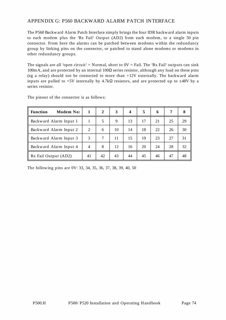
APPENDIX G: P560 BACKWARD ALARM PATCH INTERFACE
The P560 Backward Alarm Patch Interface simply brings the four IDR backward alarm inputsto each modem plus the ‘Rx Fail‘ Output (AD2) from each modem, to a single 50 pinconnector. From here the alarms can be patched between modems within the redundancygroup by linking pins on the connector, or patched to stand alone modems or modems inother redundancy groups.
The signals are all ‘open circuit‘ = Normal, short to 0V = Fail. The ‘Rx Fail‘ outputs can sink100mA, and are protected by an internal 100Ω series resistor, although any load on these pins(eg a relay) should not be connected to more than +12V externally. The backward alarminputs are pulled to +5V internally by 4.7kΩ resistors, and are protected up to ±48V by aseries resistor.
The pinout of the connector is as follows:
Function Modem No: 1 2 3 4 5 6 7 8
Backward Alarm Input 1 1 5 9 13 17 21 25 29
Backward Alarm Input 2 2 6 10 14 18 22 26 30
Backward Alarm Input 3 3 7 11 15 19 23 27 31
Backward Alarm Input 4 4 8 12 16 20 24 28 32
Rx Fail Output (AD2) 41 42 43 44 45 46 47 48
The following pins are 0V: 33, 34, 35, 36, 37, 38, 39, 40, 50
P500.H P500/P520 Installation and Operating Handbook Page 74