paraffin and nitrous oxide hybrid rocket as a mars ascent ... · 1 paraffin and nitrous oxide...
TRANSCRIPT
American Institute of Aeronautics and Astronautics
1
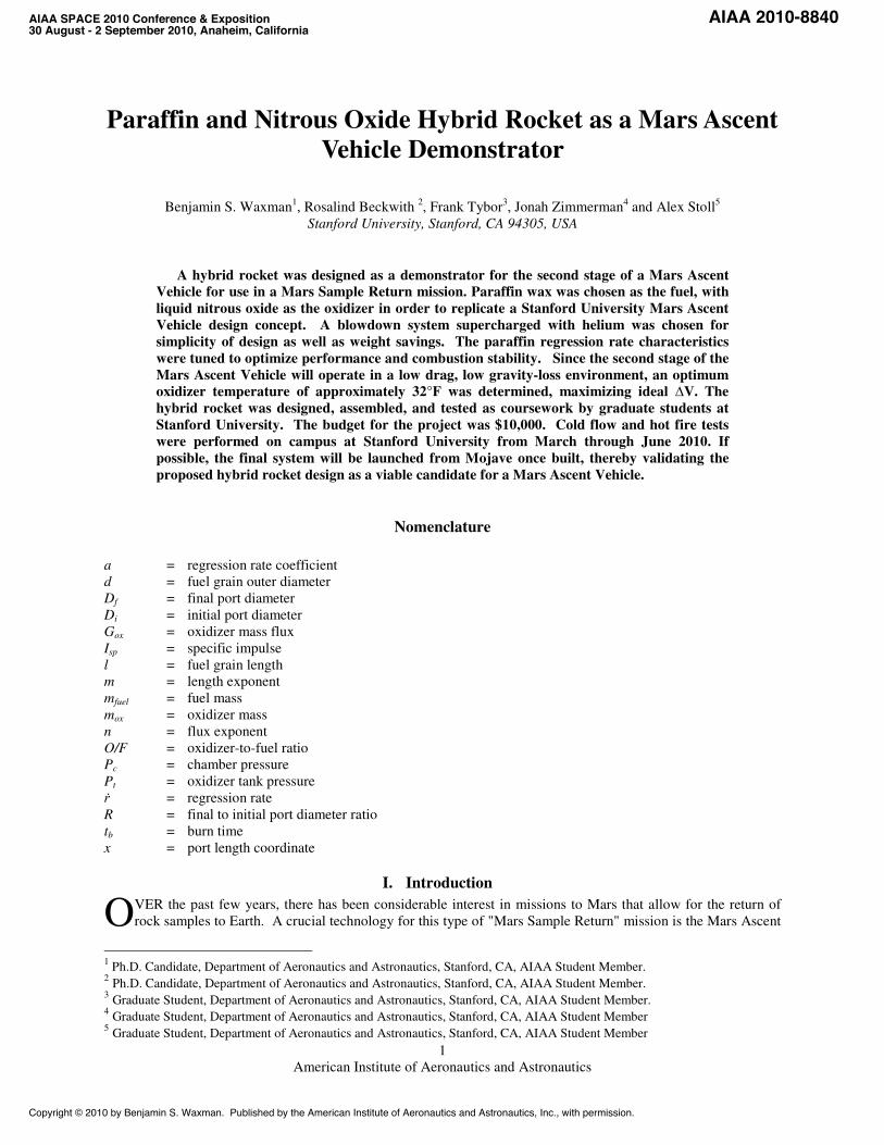
Paraffin and Nitrous Oxide Hybrid Rocket as a Mars Ascent Vehicle Demonstrator
Benjamin S. Waxman1, Rosalind Beckwith 2, Frank Tybor3, Jonah Zimmerman4 and Alex Stoll5 Stanford University, Stanford, CA 94305, USA
A hybrid rocket was designed as a demonstrator for the second stage of a Mars Ascent Vehicle for use in a Mars Sample Return mission. Paraffin wax was chosen as the fuel, with liquid nitrous oxide as the oxidizer in order to replicate a Stanford University Mars Ascent Vehicle design concept. A blowdown system supercharged with helium was chosen for simplicity of design as well as weight savings. The paraffin regression rate characteristics were tuned to optimize performance and combustion stability. Since the second stage of the Mars Ascent Vehicle will operate in a low drag, low gravity-loss environment, an optimum oxidizer temperature of approximately 32°F was determined, maximizing ideal ∆V. The hybrid rocket was designed, assembled, and tested as coursework by graduate students at Stanford University. The budget for the project was $10,000. Cold flow and hot fire tests were performed on campus at Stanford University from March through June 2010. If possible, the final system will be launched from Mojave once built, thereby validating the proposed hybrid rocket design as a viable candidate for a Mars Ascent Vehicle.
Nomenclature
a = regression rate coefficient d = fuel grain outer diameter Df = final port diameter Di = initial port diameter Gox = oxidizer mass flux Isp = specific impulse l = fuel grain length m = length exponent mfuel = fuel mass mox = oxidizer mass n = flux exponent O/F = oxidizer-to-fuel ratio Pc = chamber pressure Pt = oxidizer tank pressure ṙ = regression rate R = final to initial port diameter ratio tb = burn time x = port length coordinate
I. Introduction
VER the past few years, there has been considerable interest in missions to Mars that allow for the return of rock samples to Earth. A crucial technology for this type of "Mars Sample Return" mission is the Mars Ascent
1 Ph.D. Candidate, Department of Aeronautics and Astronautics, Stanford, CA, AIAA Student Member.
2 Ph.D. Candidate, Department of Aeronautics and Astronautics, Stanford, CA, AIAA Student Member. 3 Graduate Student, Department of Aeronautics and Astronautics, Stanford, CA, AIAA Student Member. 4 Graduate Student, Department of Aeronautics and Astronautics, Stanford, CA, AIAA Student Member 5 Graduate Student, Department of Aeronautics and Astronautics, Stanford, CA, AIAA Student Member
O
AIAA SPACE 2010 Conference & Exposition 30 August - 2 September 2010, Anaheim, California
AIAA 2010-8840
Copyright © 2010 by Benjamin S. Waxman. Published by the American Institute of Aeronautics and Astronautics, Inc., with permission.

American Institute of Aeronautics and Astronautics
2
Vehicle (MAV) that is responsible for launching rock samples from the surface into orbit around Mars, where the samples will be transferred to a return vehicle. However, due to the extreme environment of the Martian surface (specifically large temperature variations), traditional rocket architectures such as liquid and solid rockets may not be suitable for use in the as the MAV propulsion system, without significant thermal management. It has been proposed by engineers at Stanford University, Space Propulsion Group, Inc, and NASA's Jet Propulsion Laboratory that hybrid rockets may be the chemical propulsion system best suited for this type of mission, with the capability to withstand extreme temperature variations with little onboard thermal management. Specifically, high performance liquefying fueled hybrid rockets, such as those using paraffin wax as fuel are currently being proposed as possible MAV propulsion systems. The goal of this class project was to design, build, test and possibly launch a hybrid sounding rocket as a MAV demonstrator utilizing paraffin wax fuel and liquid nitrous oxide oxidizer. A group of graduate students worked with a budget of $10,000 to develop a scaled down version of the second stage of a MAV design concept over two academic quarters. The scaled down MAV second stage was part of a design concept that was considered during research performed at Stanford University.
II. Propulsion System Design
For the demonstration of a scaled down second stage MAV concept, geometric similarity of the fuel grain was chosen as the starting point for the propulsion system design. In particular, maintaining a fuel grain length to outer diameter ratio of l/d = 4.0 was set as a design requirement. However, as a restriction of the design course, the fuel grain outer diameter was limited to d = 3". From the above design requirements, the length of the fuel grain was established at l = 12". Included in the measurement of outer diameter was an insulator of 0.125" thickness, resulting in a final port diameter of Df = 2.75". To determine initial port diameter, Di, the ratio of final port diameter to initial port diameter of R = 2 was chosen to maintain structural integrity of the fuel grain under pressurization, resulting in an initial port diameter of Di = 1.375".
The propellant selection for this project was based on a MAV second stage design concept utilizing paraffin wax (C32H66) as the fuel and liquid nitrous oxide (N2O) as the oxidizer. In order to achieve optimal performance, the average oxidizer to fuel ratio by mass, O/F, was chosen to be approximately 6.75. This resulted in an oxidizer mass of mox = 12.5 lbm and a corresponding fuel mass of mfuel = 1.8 lbm. With this combination of propellants, two important design parameters were the paraffin fuel regression rate characteristics and the liquid nitrous oxide temperature.
The classical hybrid regression rate law based on that formulated by Marxman1 is shown in Eq. (1) below
(1)
where ṙ is the instantaneous time derivative of the port radius, Gox is the oxidizer mass flux through the port, x is the longitudinal location along the port, and a, n, and m are all ballistic coefficients. For the purposes of this design, it was assumed that regression rate was independent of longitudinal location along the port, which corresponds to a value of ballistic coefficient m = 0. The resulting equation for regression rate is shown in Eq. (2).
(2)
For typical systems utilizing paraffin wax and liquid nitrous oxide as the propellants, experimental work performed previously has resulted in empirical values for the ballistic coefficients a and n. However, other research in hybrid rockets has suggested a link between high values of oxidizer mass flux and large amplitude combustion instabilities during hot fire testing. In order to achieve a reasonable value of peak oxidizer mass flux (~.854 lbm/in2-s) with the propellant masses chosen above, it was necessary to utilize paraffin wax with the regression rate coefficient, a, tuned to our design. This lower regression rate tuned paraffin wax was provided by Space Propulsion Group, Inc and was the fuel used during each of the test firings performed throughout the course of the project. The resulting design burn time, tb, for this design was approximately 9.8 seconds. In order to determine the optimum temperature for the liquid nitrous oxide, it was necessary to first understand the thermochemical properties of saturated liquid nitrous oxide. A MATLAB code was written to output various thermochemical properties of saturated liquid nitrous oxide such as liquid density, vapor density, and vapor pressure based upon state polynomials provided in a technical report by Engineering Sciences Data Unit2. This code was
American Institute of Aeronautics and Astronautics
3
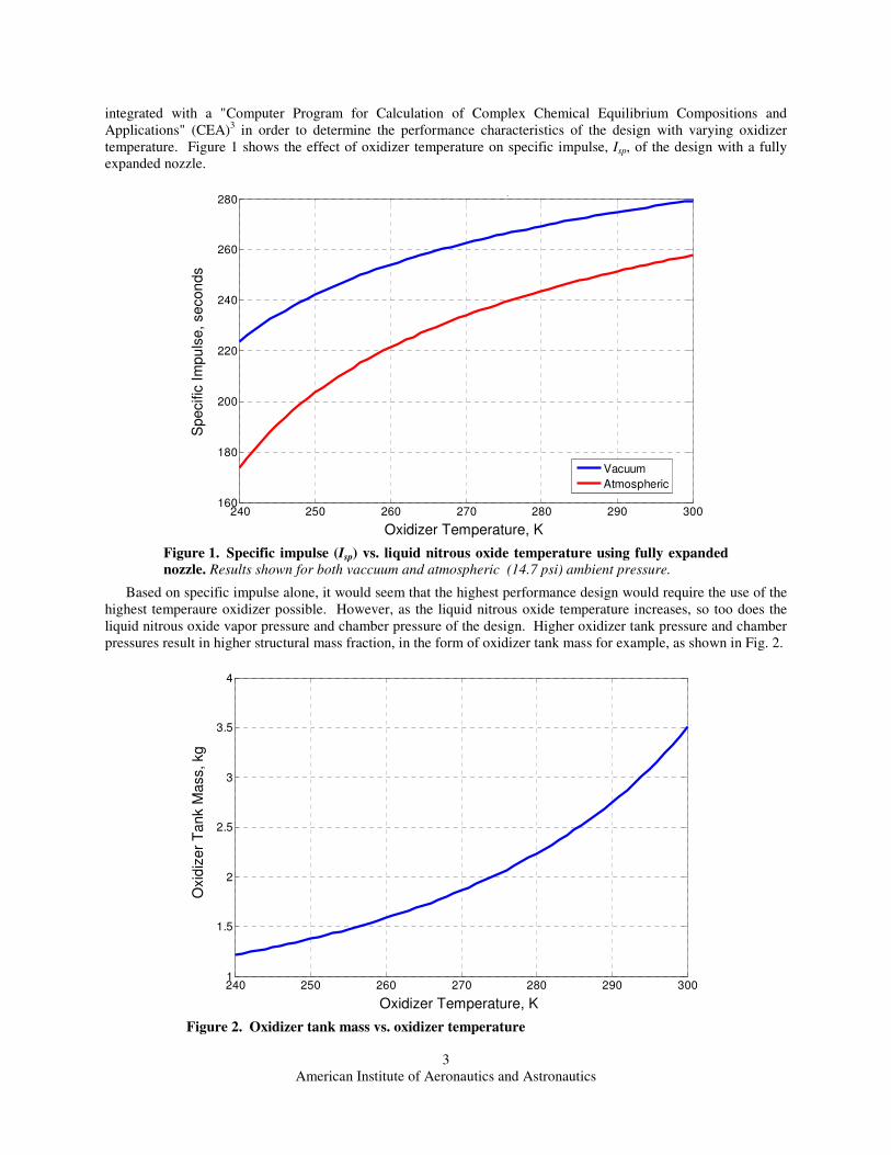
integrated with a "Computer Program for Calculation of Complex Chemical Equilibrium Compositions and Applications" (CEA)3 in order to determine the performance characteristics of the design with varying oxidizer temperature. Figure 1 shows the effect of oxidizer temperature on specific impulse, Isp, of the design with a fully expanded nozzle.
Based on specific impulse alone, it would seem that the highest performance design would require the use of the highest temperaure oxidizer possible. However, as the liquid nitrous oxide temperature increases, so too does the liquid nitrous oxide vapor pressure and chamber pressure of the design. Higher oxidizer tank pressure and chamber pressures result in higher structural mass fraction, in the form of oxidizer tank mass for example, as shown in Fig. 2.
240 250 260 270 280 290 3001
1.5
2
2.5
3
3.5
4
Tox
(K)
Mox tank (
kg
)
Figure 2. Oxidizer tank mass vs. oxidizer temperature
240 250 260 270 280 290 300160
180
200
220
240
260
280sp ox
Tox
(K)
I sp (
s)
Vacuum
Atmospheric
Figure 1. Specific impulse (Isp) vs. liquid nitrous oxide temperature using fully expanded nozzle. Results shown for both vaccuum and atmospheric (14.7 psi) ambient pressure.
Speci
fic I
mpu
lse, se
con
ds
Oxidizer Temperature, K
Oxi
diz
er
Tank
Mass
, kg
Oxidizer Temperature, K
American Institute of Aeronautics and Astronautics
4
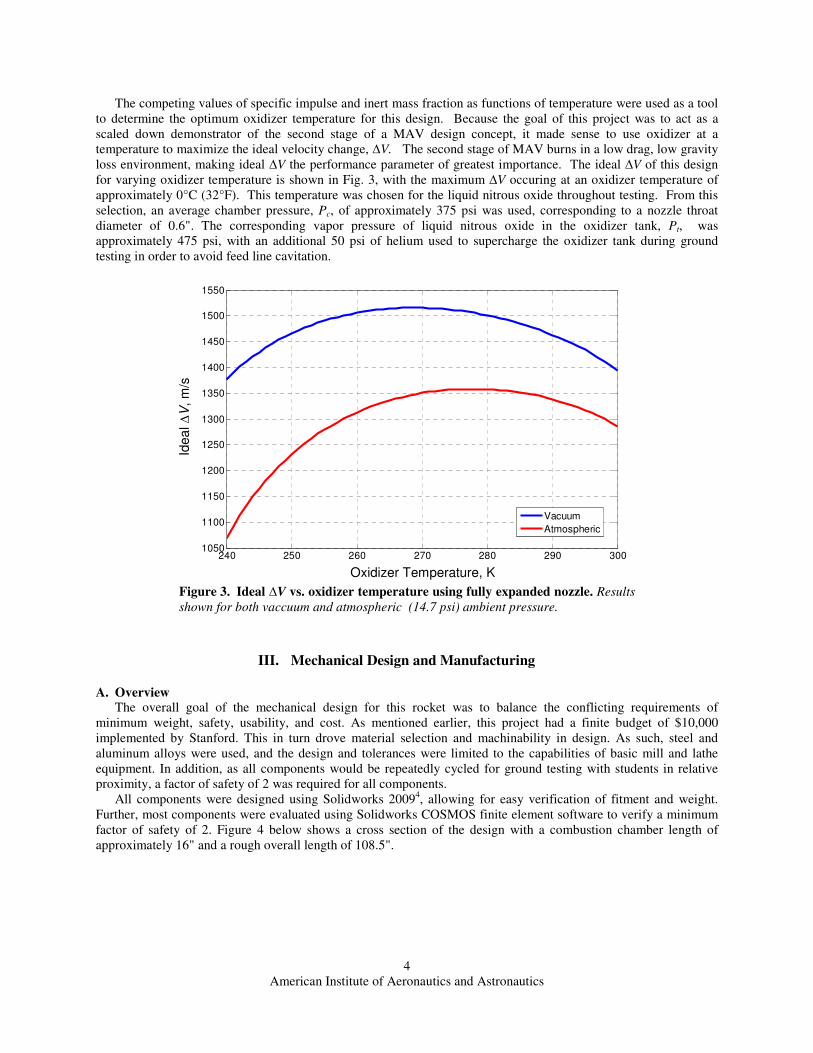
The competing values of specific impulse and inert mass fraction as functions of temperature were used as a tool to determine the optimum oxidizer temperature for this design. Because the goal of this project was to act as a scaled down demonstrator of the second stage of a MAV design concept, it made sense to use oxidizer at a temperature to maximize the ideal velocity change, ∆V. The second stage of MAV burns in a low drag, low gravity loss environment, making ideal ∆V the performance parameter of greatest importance. The ideal ∆V of this design for varying oxidizer temperature is shown in Fig. 3, with the maximum ∆V occuring at an oxidizer temperature of approximately 0°C (32°F). This temperature was chosen for the liquid nitrous oxide throughout testing. From this selection, an average chamber pressure, Pc, of approximately 375 psi was used, corresponding to a nozzle throat diameter of 0.6". The corresponding vapor pressure of liquid nitrous oxide in the oxidizer tank, Pt, was approximately 475 psi, with an additional 50 psi of helium used to supercharge the oxidizer tank during ground testing in order to avoid feed line cavitation.
III. Mechanical Design and Manufacturing
A. Overview The overall goal of the mechanical design for this rocket was to balance the conflicting requirements of minimum weight, safety, usability, and cost. As mentioned earlier, this project had a finite budget of $10,000 implemented by Stanford. This in turn drove material selection and machinability in design. As such, steel and aluminum alloys were used, and the design and tolerances were limited to the capabilities of basic mill and lathe equipment. In addition, as all components would be repeatedly cycled for ground testing with students in relative proximity, a factor of safety of 2 was required for all components.
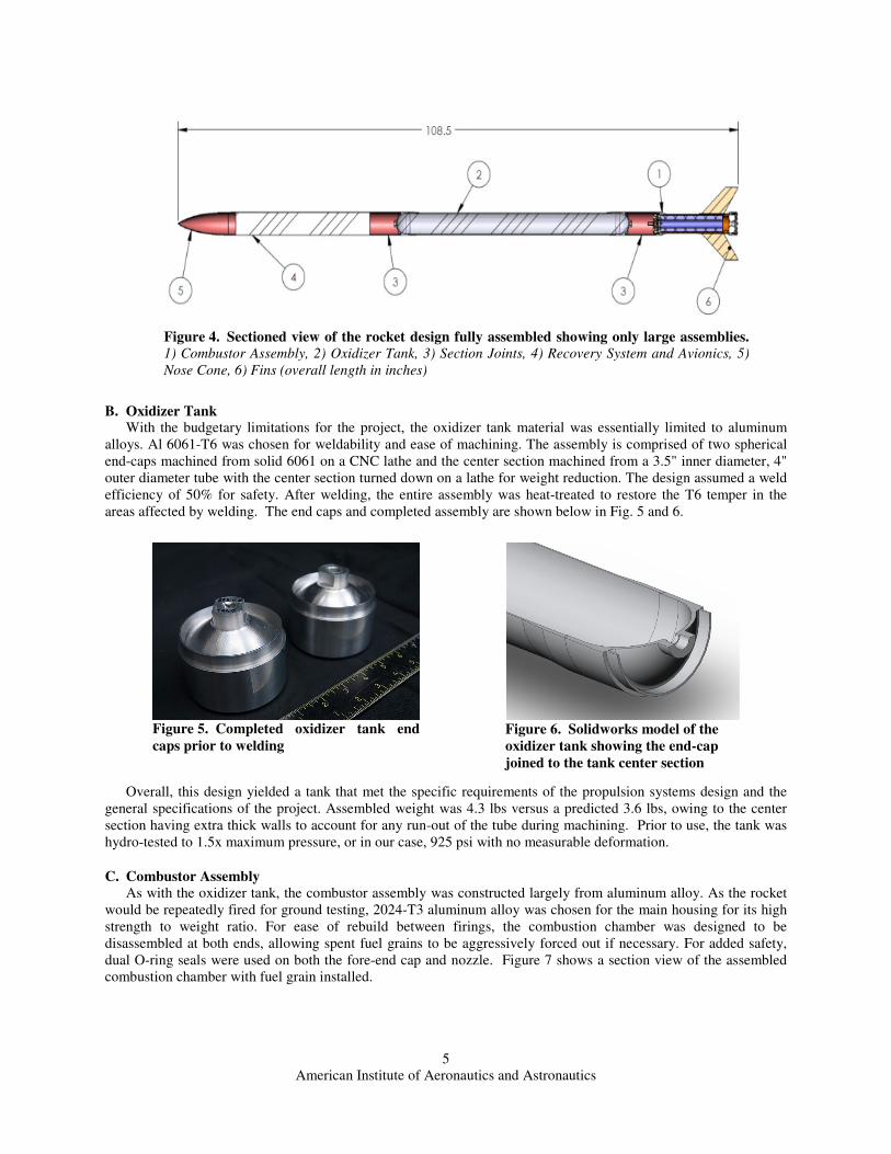
All components were designed using Solidworks 20094, allowing for easy verification of fitment and weight. Further, most components were evaluated using Solidworks COSMOS finite element software to verify a minimum factor of safety of 2. Figure 4 below shows a cross section of the design with a combustion chamber length of approximately 16" and a rough overall length of 108.5".
240 250 260 270 280 290 3001050
1100
1150
1200
1250
1300
1350
1400
1450
1500
1550
Tox
(K)
Ide
al !
V (
m/s
)
Vacuum
Atmospheric
Figure 3. Ideal ∆V vs. oxidizer temperature using fully expanded nozzle. Results shown for both vaccuum and atmospheric (14.7 psi) ambient pressure.
Idea
l ∆V
, m
/s
Oxidizer Temperature, K
American Institute of Aeronautics and Astronautics
5
B. Oxidizer Tank With the budgetary limitations for the project, the oxidizer tank material was essentially limited to aluminum alloys. Al 6061-T6 was chosen for weldability and ease of machining. The assembly is comprised of two spherical end-caps machined from solid 6061 on a CNC lathe and the center section machined from a 3.5" inner diameter, 4" outer diameter tube with the center section turned down on a lathe for weight reduction. The design assumed a weld efficiency of 50% for safety. After welding, the entire assembly was heat-treated to restore the T6 temper in the areas affected by welding. The end caps and completed assembly are shown below in Fig. 5 and 6.
Overall, this design yielded a tank that met the specific requirements of the propulsion systems design and the general specifications of the project. Assembled weight was 4.3 lbs versus a predicted 3.6 lbs, owing to the center section having extra thick walls to account for any run-out of the tube during machining. Prior to use, the tank was hydro-tested to 1.5x maximum pressure, or in our case, 925 psi with no measurable deformation.
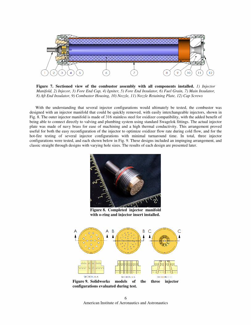
C. Combustor Assembly As with the oxidizer tank, the combustor assembly was constructed largely from aluminum alloy. As the rocket would be repeatedly fired for ground testing, 2024-T3 aluminum alloy was chosen for the main housing for its high strength to weight ratio. For ease of rebuild between firings, the combustion chamber was designed to be disassembled at both ends, allowing spent fuel grains to be aggressively forced out if necessary. For added safety, dual O-ring seals were used on both the fore-end cap and nozzle. Figure 7 shows a section view of the assembled combustion chamber with fuel grain installed.
Figure 6. Solidworks model of the oxidizer tank showing the end-cap joined to the tank center section
Figure 5. Completed oxidizer tank end caps prior to welding
Figure 4. Sectioned view of the rocket design fully assembled showing only large assemblies. 1) Combustor Assembly, 2) Oxidizer Tank, 3) Section Joints, 4) Recovery System and Avionics, 5) Nose Cone, 6) Fins (overall length in inches)
American Institute of Aeronautics and Astronautics
6
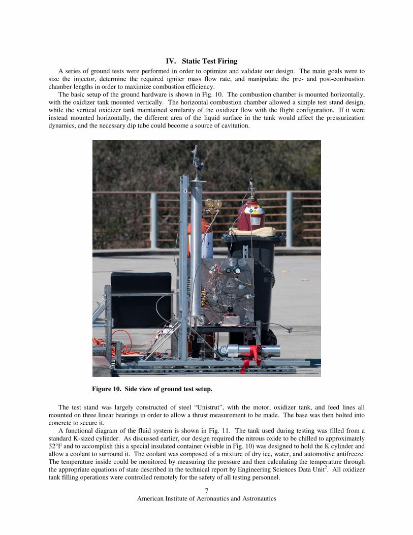
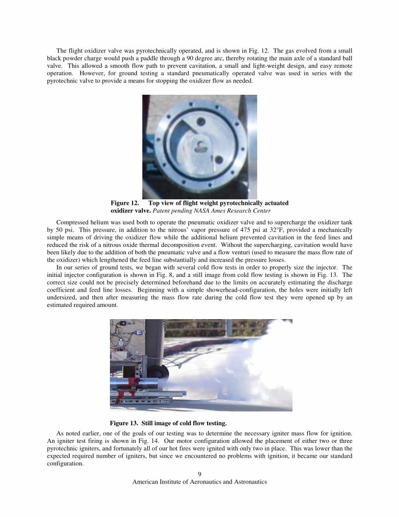
With the understanding that several injector configurations would ultimately be tested, the combustor was designed with an injector manifold that could be quickly removed, with easily interchangeable injectors, shown in Fig. 8. The outer injector manifold is made of 316 stainless steel for oxidizer compatibility, with the added benefit of being able to connect directly to valving and plumbing system using standard Swagelok fittings. The actual injector plate was made of navy brass for ease of machining and a high thermal conductivity. This arrangement proved useful for both the easy reconfiguration of the injector to optimize oxidizer flow rate during cold flow, and for the hot-fire testing of several injector configurations with minimal turnaround time. In total, three injector configurations were tested, and each shown below in Fig. 9. These designs included an impinging arrangement, and classic straight through designs with varying hole sizes. The results of each design are presented later.
Figure 9. Solidworks models of the three injector configurations evaluated during test.
Figure 8. Completed injector manifold with o-ring and injector insert installed.
Figure 7. Sectioned view of the combustor assembly with all components installed. 1) Injector Manifold, 2) Injecor, 3) Fore End Cap, 4) Igniter, 5) Fore End Insulator, 6) Fuel Grain, 7) Main Insulator, 8) Aft End Insulator, 9) Combustor Housing, 10) Nozzle, 11) Nozzle Retaining Plate, 12) Cap Screws
American Institute of Aeronautics and Astronautics
7
IV. Static Test Firing
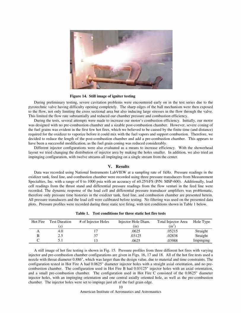
A series of ground tests were performed in order to optimize and validate our design. The main goals were to size the injector, determine the required igniter mass flow rate, and manipulate the pre- and post-combustion chamber lengths in order to maximize combustion efficiency. The basic setup of the ground hardware is shown in Fig. 10. The combustion chamber is mounted horizontally, with the oxidizer tank mounted vertically. The horizontal combustion chamber allowed a simple test stand design, while the vertical oxidizer tank maintained similarity of the oxidizer flow with the flight configuration. If it were instead mounted horizontally, the different area of the liquid surface in the tank would affect the pressurization dynamics, and the necessary dip tube could become a source of cavitation.
The test stand was largely constructed of steel “Unistrut”, with the motor, oxidizer tank, and feed lines all mounted on three linear bearings in order to allow a thrust measurement to be made. The base was then bolted into concrete to secure it. A functional diagram of the fluid system is shown in Fig. 11. The tank used during testing was filled from a standard K-sized cylinder. As discussed earlier, our design required the nitrous oxide to be chilled to approximately 32°F and to accomplish this a special insulated container (visible in Fig. 10) was designed to hold the K cylinder and allow a coolant to surround it. The coolant was composed of a mixture of dry ice, water, and automotive antifreeze. The temperature inside could be monitored by measuring the pressure and then calculating the temperature through the appropriate equations of state described in the technical report by Engineering Sciences Data Unit2. All oxidizer tank filling operations were controlled remotely for the safety of all testing personnel.
Figure 10. Side view of ground test setup.

American Institute of Aeronautics and Astronautics
8
In order to fill the run tank from the K cylinder, a vent at the top of the run tank was controlled to reduce the pressure in the run tank, and thus drive fluid flow from the cylinder where the pressure was higher. As nitrous oxide boiled off and escaped through the vent, the temperature in the run tank would drop as a result of the energy lost through vaporization. Therefore, keeping the tank’s temperature near our required 32°F despite the lack of insulation on the supply piping and on the run tank itself was trivial. Measuring the amount of nitrous oxide that was flowing into the run tank was problematic. The mass of the combined K cylinder, insulated container, and coolant were monitored, but large fluctuations in the reading were induced by boil off of the dry ice and wind. More importantly, because we were simultaneously venting vapor from the run tank while filling the readings were not reliable. A more reliably measurement system involved simply marking the frost line on the run tank and calculating the fill level from geometry.
Figure 11. Process and instrumentation diagram for ground test setup.
American Institute of Aeronautics and Astronautics
9
The flight oxidizer valve was pyrotechnically operated, and is shown in Fig. 12. The gas evolved from a small black powder charge would push a paddle through a 90 degree arc, thereby rotating the main axle of a standard ball valve. This allowed a smooth flow path to prevent cavitation, a small and light-weight design, and easy remote operation. However, for ground testing a standard pneumatically operated valve was used in series with the pyrotechnic valve to provide a means for stopping the oxidizer flow as needed.
Compressed helium was used both to operate the pneumatic oxidizer valve and to supercharge the oxidizer tank by 50 psi. This pressure, in addition to the nitrous’ vapor pressure of 475 psi at 32°F, provided a mechanically simple means of driving the oxidizer flow while the additional helium prevented cavitation in the feed lines and reduced the risk of a nitrous oxide thermal decomposition event. Without the supercharging, cavitation would have been likely due to the addition of both the pneumatic valve and a flow venturi (used to measure the mass flow rate of the oxidizer) which lengthened the feed line substantially and increased the pressure losses. In our series of ground tests, we began with several cold flow tests in order to properly size the injector. The initial injector configuration is shown in Fig. 8, and a still image from cold flow testing is shown in Fig. 13. The correct size could not be precisely determined beforehand due to the limits on accurately estimating the discharge coefficient and feed line losses. Beginning with a simple showerhead-configuration, the holes were initially left undersized, and then after measuring the mass flow rate during the cold flow test they were opened up by an estimated required amount.
As noted earlier, one of the goals of our testing was to determine the necessary igniter mass flow for ignition. An igniter test firing is shown in Fig. 14. Our motor configuration allowed the placement of either two or three pyrotechnic igniters, and fortunately all of our hot fires were ignited with only two in place. This was lower than the expected required number of igniters, but since we encountered no problems with ignition, it became our standard configuration.
Figure 13. Still image of cold flow testing.
Figure 12. Top view of flight weight pyrotechnically actuated oxidizer valve. Patent pending NASA Ames Research Center
American Institute of Aeronautics and Astronautics
10
During preliminary testing, severe cavitation problems were encountered early on in the test series due to the pyrotechnic valve having difficulty opening completely. The sharp edges of the ball mechanism were then exposed to the flow, not only limiting the cross sectional area but also inducing large stresses in the flow through the valve. This limited the flow rate substantially and reduced our chamber pressure and combustion efficiency. During the tests, several attempts were made to increase our motor’s combustion efficiency. Initially, our motor was designed with no pre-combustion chamber and a sizable post-combustion chamber. However, severe coning of the fuel grains was evident in the first few hot fires, which we believed to be caused by the finite time (and distance) required for the oxidizer to vaporize before it could mix with the fuel vapors and support combustion. Therefore, we decided to reduce the length of the post-combustion chamber and add a pre-combustion chamber. This appears to have been a successful modification, as the fuel grain coning was reduced considerably. Different injector configurations were also evaluated as a means to increase efficiency. With the showerhead layout we tried changing the distribution of injector area by making the holes smaller. In addition, we also tried an impinging configuration, with twelve streams all impinging on a single stream from the center.
V. Results
Data was recorded using National Instruments LabVIEW at a sampling rate of 1kHz. Pressure readings in the oxidizer tank, feed line, and combustion chamber were recorded using three pressure transducers from Measurement Specialties, Inc. with a range of 0 to 1000 psia with an accuracy of ±0.25%FS (P/N: MSP-600). Additionally, load cell readings from the thrust stand and differential pressure readings from the flow venturi in the feed line were recorded. The dynamic response of the load cell and differential pressure transducer amplifiers was problematic, therefore only pressure time histories in the oxidizer tank, feed line, and combustion chamber are presented herein. All pressure transducers and the load cell were calibrated before testing. No filtering was used on the presented data plots. Pressure profiles were recorded during three static test firing, with test conditions shown in Table 1 below.
Table 1. Test conditions for three static hot fire tests
A still image of hot fire testing is shown in Fig. 15. Pressure profiles from three different hot fires with varying injector and pre-combustion chamber configurations are given in Figs. 16, 17 and 18. All of the hot fire tests used a nozzle with throat diameter 0.886", which was larger than the design value, due to material and time constraints. The configuration tested in Hot Fire A had 0.0625" diameter injector holes with a straight axial orientation, and no pre-combustion chamber. The configuration used in Hot Fire B had 0.03125" injector holes with an axial orientation, and a small pre-combustion chamber. The configuration used in Hot Fire C consisted of the 0.0625" diameter injector holes, with an impinging orientation and one central axially oriented hole, as well as the pre-combustion chamber. The injector holes were set to impinge just aft of the fuel grain edge.
Hot Fire Test Duration # of Injector Holes Injector Hole Diam. Total Injector Area Hole Type (s) (in) (in2)
A 4.0 17 .0625 .05215 Straight B 2.5 37 .03125 .02838 Straight C 5.1 13 .0625 .03988 Impinging
Figure 14. Still image of igniter testing

American Institute of Aeronautics and Astronautics
11
Figure 15. Still image of hot fire testing.
0 1 2 3 4 50
100
200
300
400
500
600
Time, seconds
Pre
ssu
re, p
sia
P ox tank
P feedline
P chamber
Figure 16. Hot Fire A pressure profiles for oxidizer tank, feedline, and combustion chamber.

American Institute of Aeronautics and Astronautics
12
The impinging injector, Hot Fire C, saw the highest average chamber pressure, though it was clearly the least stable configuration with pressure spikes nearly doubling the average magnitude of pressure. The impinging streams may have improved atomization of the injector streams, however they most likely created a more unstable
0 0.5 1 1.5 2 2.5 3
0
100
200
300
400
500
600
Time, seconds
Pre
ssu
re, p
sia
P ox tank
P feedline
P chamber
gasphaseburn
Figure 17. Hot Fire B pressure profiles for oxidizer tank, feedline, and combustion chamber.
0 0.5 1 1.5 2 2.50
100
200
300
400
500
600
Time, seconds
Pre
ssu
re, p
sia
P ox tank
P feedline
P chamber
Figure 18. Hot Fire C pressure profiles for oxidizer tank, feedline, and combustion chamber. Only first 2.5 seconds recorded due to data acquisition computer malfunction.
American Institute of Aeronautics and Astronautics
13
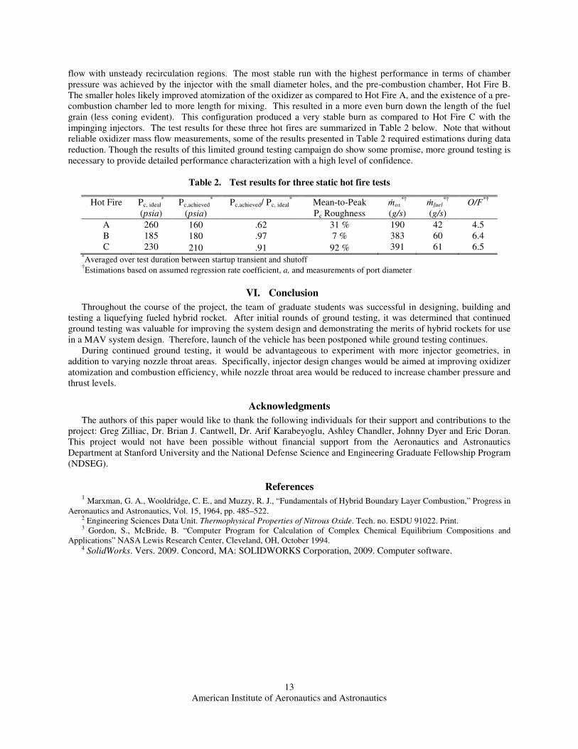
flow with unsteady recirculation regions. The most stable run with the highest performance in terms of chamber pressure was achieved by the injector with the small diameter holes, and the pre-combustion chamber, Hot Fire B. The smaller holes likely improved atomization of the oxidizer as compared to Hot Fire A, and the existence of a pre-combustion chamber led to more length for mixing. This resulted in a more even burn down the length of the fuel grain (less coning evident). This configuration produced a very stable burn as compared to Hot Fire C with the impinging injectors. The test results for these three hot fires are summarized in Table 2 below. Note that without reliable oxidizer mass flow measurements, some of the results presented in Table 2 required estimations during data reduction. Though the results of this limited ground testing campaign do show some promise, more ground testing is necessary to provide detailed performance characterization with a high level of confidence.
Table 2. Test results for three static hot fire tests
*Averaged over test duration between startup transient and shutoff †
Estimations based on assumed regression rate coefficient, a, and measurements of port diameter
VI. Conclusion
Throughout the course of the project, the team of graduate students was successful in designing, building and testing a liquefying fueled hybrid rocket. After initial rounds of ground testing, it was determined that continued ground testing was valuable for improving the system design and demonstrating the merits of hybrid rockets for use in a MAV system design. Therefore, launch of the vehicle has been postponed while ground testing continues.
During continued ground testing, it would be advantageous to experiment with more injector geometries, in addition to varying nozzle throat areas. Specifically, injector design changes would be aimed at improving oxidizer atomization and combustion efficiency, while nozzle throat area would be reduced to increase chamber pressure and thrust levels.
Acknowledgments
The authors of this paper would like to thank the following individuals for their support and contributions to the project: Greg Zilliac, Dr. Brian J. Cantwell, Dr. Arif Karabeyoglu, Ashley Chandler, Johnny Dyer and Eric Doran. This project would not have been possible without financial support from the Aeronautics and Astronautics Department at Stanford University and the National Defense Science and Engineering Graduate Fellowship Program (NDSEG).
References 1 Marxman, G. A., Wooldridge, C. E., and Muzzy, R. J., “Fundamentals of Hybrid Boundary Layer Combustion,” Progress in Aeronautics and Astronautics, Vol. 15, 1964, pp. 485–522. 2 Engineering Sciences Data Unit. Thermophysical Properties of Nitrous Oxide. Tech. no. ESDU 91022. Print. 3 Gordon, S., McBride, B. “Computer Program for Calculation of Complex Chemical Equilibrium Compositions and Applications” NASA Lewis Research Center, Cleveland, OH, October 1994. 4 SolidWorks. Vers. 2009. Concord, MA: SOLIDWORKS Corporation, 2009. Computer software.
Hot Fire Pc, ideal* Pc,achieved
* Pc,achieved/ Pc, ideal* Mean-to-Peak ṁox
*† ṁfuel*† O/F*†
(psia) (psia) Pc Roughness (g/s) (g/s) A 260 160 .62 31 % 190 42 4.5 B 185 180 .97 7 % 383 60 6.4 C 230 210 .91 92 % 391 61 6.5