parallel-perspective stereo mosaicszhu/prism_iccv01.pdfparallel-perspective, which have perspective...
TRANSCRIPT
The Eighth IEEE International Conference on Computer Vision, Vancouver, Canada, July 9-12,2001
1
Parallel-Perspective Stereo Mosaics
Zhigang Zhu, Edward M. Riseman, Allen R. HansonDepartment of Computer Science, University of Massachusetts at Amherst, MA 01003
Email: {zhu, riseman, hanson}@cs.umass.edu
Abstract
In this paper we present a novel method for automaticallyand efficiently generating stereoscopic mosaics by seamlessregistration of optical data collected by a video cameramounted on an airborne platform that undergoes dominanttranslational motion. There are four critical points discussedin this paper: 1) Using a parallel-perspective representation,a pair of geometrically registered stereo mosaics can beconstructed before we explicitly recover any 3D informationunder rather general motion. 2) A PRISM (parallel rayinterpolation for stereo mosaicing) technique is proposed tomake stereo mosaics seamless in the presence of motionparallax and for rather arbitrary scenes. A fast PRISMalgorithm is presented and issues on stitching point selectionand occlusion handling are discussed. 3) The epipolargeometry of parallel-perspective stereo mosaics generatedunder constrained 6 DOF motion is formulated, which showsoptimal baselines, easy search for correspondence andconstant depth resolution. 4) The proposed methods for thegeneration of stereo mosaics and then the reconstruction of a3D map are efficient in both computation and storage.Experimental results on long video sequences are given.
1. Introduction
Recently, there have been attempts in a variety of applicationsto add 3D information into an image-based mosaicrepresentation. Creating stereo mosaics from two rotatingcameras was proposed by Huang & Hung [1]. More practicalis the generation of stereo mosaics from a single off-centerrotating camera by Peleg & Ben-Ezra [2] and Shum &Szeliski [3]. In fact, the idea of generating stereo panoramasfor either an off-center rotating camera or a translatingcamera can be traced back to the earlier work in robot visionapplications by Ishiguro, et al [4] and Zheng & Tsuji [5]. Theattraction of the recent studies on off-center rotating cameraslies in how to make stereo mosaics with nice epipolargeometry and high image qualities and how to use them inimage-based rendering. However, in stereo mosaics with arotating camera, the viewpoints -- therefore the parallax -- arelimited to images taken from a very small area, and theviewers are constrained to rotationally viewing the stereorepresentations. Translational motion, on the other hand, isthe typical prevalent sensor motion during ground vehiclenavigation [5] or aerial surveys[6]. In [2] the authorsmentioned that the same techniques developed for a rotatingcamera could be applied to a translating camera, but it turnsout that there has been little serious work on this topic. Arotating camera can be easily controlled to achieve the desiredmotion. On the contrary, the translation of a camera over a
large distance is much hard to control. How to generate stereomosaics under a rather general motion with dominanttranslation is still an unsolved problem and is the focus ofthis paper.
1.1. Related workIn this paper, we will address the problem of creatingseamless and geometrically-registered 3D mosaics from amoving camera, undertaking a rather general motion andallowing viewpoints change over a large scale. Obviously useof standard 2D mosaicing techniques based on 2D imagetransformations such as a manifold projection [7] cannotgenerate a seamless mosaic in the presence of large motionparallax, particularly in the case of surfaces that are highlyirregular or with large differences in heights. Many researcheson seamless mosaics deal with video from a rotating camera.As a typical example, in generating seamless 2D mosaicsfrom a hand-held camera, Shum & Szeliski [8] used a localalignment (de-ghosting) technique to compensate for thesmall amount of motion parallax introduced by smalltranslations of the camera. Rousso, et al [9] suggested that a2D orthogonal projection could be generated by taking acollection of strips, each with a width of one pixel, frominterpolated camera views in between the original camerapositions, but details were not provided. Kumar, et al [10]dealt with the geo-registration problem by utilizing anavailable geo-referenced aerial image with broader coverage,as well as an accompanying co-registered digital elevationmap. In more general cases for generating image mosaicswith parallax, several techniques have been proposed toexplicitly estimate the camera motion and residual parallax byrecovering a projective depth value for each pixel [11-13].These approaches could produce geo-referenced mosaics;however, they are computationally intense, and since a finalmosaic is represented in a reference perspective view, therecould be serious occlusion problems due to large viewpointdifferences between a single reference view and the rest ofthe views in the image sequence.
An important part of the work that follows is a new mosaicrepresentation that can support seamless mosaicing under arather general motion and also can capture inherent 3Dinformation during the mosaic process. Aparallel-perspectivemodel is selected for representing mosaics in ourapproach since it is the closest form to the originalperspective video sequence under large motion parallax, yetits geometry allows us to generate seamless stereo mosaics.To accomplish this, we propose a novel technique calledPRISM (parallel ray interpolation for stereo mosaicing) toefficiently convert the sequence ofperspectiveimages withdramatically changing viewpoints into the parallel-perspective stereo mosaics.
The Eighth IEEE International Conference on Computer Vision, Vancouver, Canada, July 9-12,2001
2
2. Generalized Parallel-Perspective Stereo
The basic idea of parallel-perspective stereo mosaics under1D translation has been proposed by Zhu et al [6], and Chai& Shum [14], showing the advantages of depth recovery fromparallel projection in both epipolar geometry and depthresolution. Assume the motion of a camera is an ideal 1Dtranslation, the optical axis is perpendicular to the motion,and the frames are dense enough. Then, we can generate twospatio-temporal images by extracting two columns1 of pixels(perpendicular to the motion) at the front and rear edges ofeach frame in motion. The mosaic images thus generated areparallel-perspective, which have perspective projection in thedirection perpendicular to the motion and parallel projectionin the motion direction. In addition, these mosaics areobtained from two different oblique viewing angles of asingle camera’s field of view, so that a stereo pair of left andright mosaics captures the inherent 3D information.
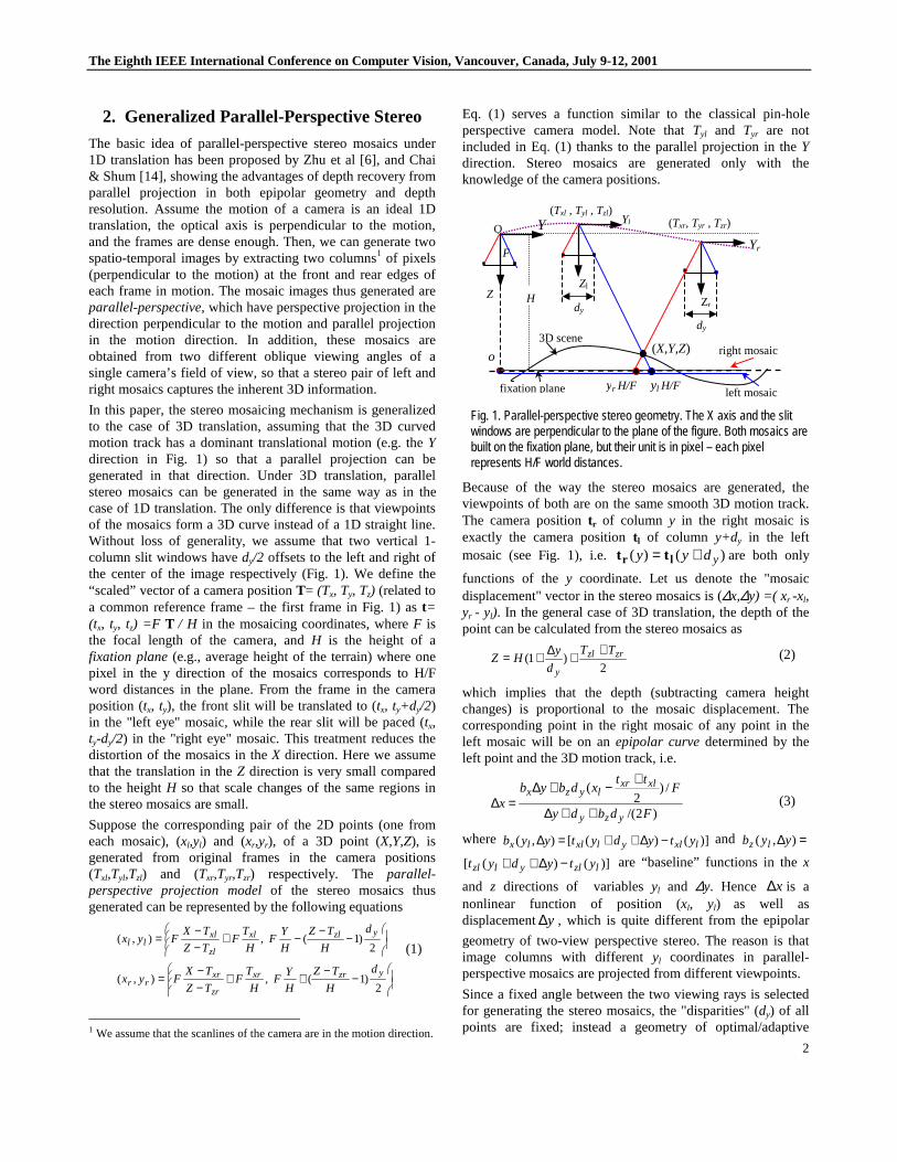
In this paper, the stereo mosaicing mechanism is generalizedto the case of 3D translation, assuming that the 3D curvedmotion track has a dominant translational motion (e.g. theYdirection in Fig. 1) so that a parallel projection can begenerated in that direction. Under 3D translation, parallelstereo mosaics can be generated in the same way as in thecase of 1D translation. The only difference is that viewpointsof the mosaics form a 3D curve instead of a 1D straight line.Without loss of generality, we assume that two vertical 1-column slit windows havedy/2 offsets to the left and right ofthe center of the image respectively (Fig. 1). We define the“scaled” vector of a camera positionT= (Tx, Ty, Tz) (related toa common reference frame – the first frame in Fig. 1) ast=(tx, ty, tz) =F T / H in the mosaicing coordinates, whereF isthe focal length of the camera, andH is the height of afixation plane(e.g., average height of the terrain) where onepixel in the y direction of the mosaics corresponds to H/Fword distances in the plane. From the frame in the cameraposition (tx, ty), the front slit will be translated to (tx, ty+dy/2)in the "left eye" mosaic, while the rear slit will be paced (tx,ty-dy/2) in the "right eye" mosaic. This treatment reduces thedistortion of the mosaics in theX direction. Here we assumethat the translation in theZ direction is very small comparedto the heightH so that scale changes of the same regions inthe stereo mosaics are small.
Suppose the corresponding pair of the 2D points (one fromeach mosaic), (xl,yl) and (xr,yr), of a 3D point (X,Y,Z), isgenerated from original frames in the camera positions(Txl,Tyl,Tzl) and (Txr,Tyr,Tzr) respectively. The parallel-perspective projection modelof the stereo mosaics thusgenerated can be represented by the following equations
ÿÿ�
����
�−
−++
−−
=
ÿÿ�
����
�−
−−+
−−
=
2)1(,),(
2)1(,),(
yzrxr
zr
xrrr
yzlxl
zl
xlll
d
H
TZ
H
YF
H
TF
TZ
TXFyx
d
H
TZ
H
YF
H
TF
TZ
TXFyx
(1)
1 We assume that the scanlines of the camera are in the motion direction.
Eq. (1) serves a function similar to the classical pin-holeperspective camera model. Note thatTyl and Tyr are notincluded in Eq. (1) thanks to the parallel projection in theYdirection. Stereo mosaics are generated only with theknowledge of the camera positions.
Fig. 1. Parallel-perspective stereo geometry. The X axis and the slitwindows are perpendicular to the plane of the figure. Both mosaics arebuilt on the fixation plane, but their unit is in pixel – each pixelrepresents H/F world distances.
Because of the way the stereo mosaics are generated, theviewpoints of both are on the same smooth 3D motion track.The camera positiontr of column y in the right mosaic isexactly the camera positiontl of column y+dy in the leftmosaic (see Fig. 1), i.e. )()( ydyy += lr tt are both only
functions of they coordinate. Let us denote the "mosaicdisplacement" vector in the stereo mosaics is (∆x,∆y) =( xr -xl,yr - yl). In the general case of 3D translation, the depth of thepoint can be calculated from the stereo mosaics as
2)1( zrzl
y
TT
d
yHZ
++∆+= (2)
which implies that the depth (subtracting camera heightchanges) is proportional to the mosaic displacement. Thecorresponding point in the right mosaic of any point in theleft mosaic will be on anepipolar curvedetermined by theleft point and the 3D motion track, i.e.
)2/(
/)2
(
Fdbdy
Ftt
xdbybx
yzy
xlxrlyzx
++∆
+−+∆=∆ (3)
where )]()([),( lxlylxllx ytydytyyb −∆++=∆ and =∆ ),( yyb lz
)]()([ lzlylzl ytydyt −∆++ are “baseline” functions in thex
and z directions of variablesyl and ∆y. Hence x∆ is anonlinear function of position (xl, yl) as well asdisplacement y∆ , which is quite different from the epipolar
geometry of two-view perspective stereo. The reason is thatimage columns with differentyl coordinates in parallel-perspective mosaics are projected from different viewpoints.
Since a fixed angle between the two viewing rays is selectedfor generating the stereo mosaics, the "disparities" (dy) of allpoints are fixed; instead a geometry of optimal/adaptive
dy
Yr
Zr
(Txr, Tyr , Tzr)
F
Y
Z
O
H
Yl
dy
Zl
(Txl , Tyl , Tzl)
(X,Y,Z)o
yl H/F
right mosaic
left mosaic
3D scene
fixation plane yr H/F
The Eighth IEEE International Conference on Computer Vision, Vancouver, Canada, July 9-12,2001
3
baselines (by= dy+∆y) for all the points is created. In otherwords, for any point in the left mosaic, searching for thematch point in the right mosaic means finding an originalframe in which this match pair has a pre-defined disparity (bythe distance of the two slit windows) and hence has anadaptive baseline depending on the depth of the point.
If the motion of the camera is constrained to a 2D translationin the XY plane (i.e.Tz=0), the depth of the point can besimply derived as
)1(yd
yHZ
∆+= (4)
The stereo mosaic displacement∆y is a function of the depthvariation of the scene around the fixation plane H (which isalmost true in the case of 3D translation). It is interesting tonote that since the selection of the two mosaic coordinatesystems brings a constant shiftdy to the scaled "baseline", itproduces the fixation of the stereo mosaics to a horizontal"fixation plane" of an average heightH. This is highlydesirable for both stereo matching and stereoscopic viewing.The epipolar curve under 2D translation becomes
ylx dy
yyybx
+∆∆∆=∆ ),( (5)
which is only a function of positionyl and y∆ , but is
independent of the coordinatex. We have three conclusionsfor the epipolar geometry of the parallel-perspective stereo:
1) In the general case of 3D translation, if we know therange of depth variation plus camera height changes, mZ∆± ,
the search region for the corresponding point in the rightmosaic is ],[ m
ym
yZ
H
dZ
H
dy ∆+∆−∈∆ (from Eq. (2)), and along an
epipolar curve, which is different for every point (xl, yl) ingeneral (Eq. (3)).
2) In the case of 2D translation, the epipolar curve for agiven point (xl,yl) in the left mosaic passes through thelocation (xl,yl) in the right mosaic (Eq. (4)), which impliesthat the stereo mosaics are aligned for all the points whosedepths areH. The same epipolar curve function (ofyl and∆y) is applied to all the points in the left mosaic with thesameyl coordinate.
3). In the ideal casewhere the viewpoints of stereomosaics lie in a 1D straight line, the epipolar curves will turnout to be horizontal lines. Therefore we can apply most of theexisting stereo match algorithms for rectified perspectivestereo with little modification.
3. Mosaicing under 6 DOF Motion
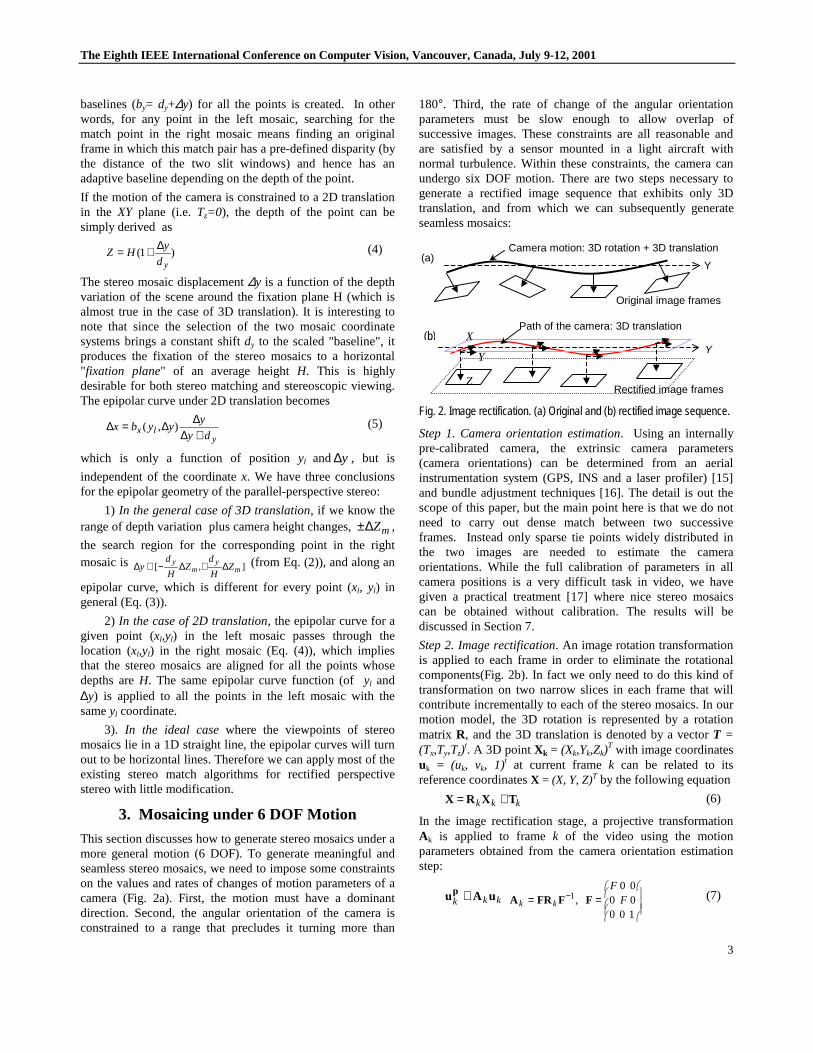
This section discusses how to generate stereo mosaics under amore general motion (6 DOF). To generate meaningful andseamless stereo mosaics, we need to impose some constraintson the values and rates of changes of motion parameters of acamera (Fig. 2a). First, the motion must have a dominantdirection. Second, the angular orientation of the camera isconstrained to a range that precludes it turning more than
180°. Third, the rate of change of the angular orientationparameters must be slow enough to allow overlap ofsuccessive images. These constraints are all reasonable andare satisfied by a sensor mounted in a light aircraft withnormal turbulence. Within these constraints, the camera canundergo six DOF motion. There are two steps necessary togenerate a rectified image sequence that exhibits only 3Dtranslation, and from which we can subsequently generateseamless mosaics:
Fig. 2. Image rectification. (a) Original and (b) rectified image sequence.
Step 1. Camera orientation estimation. Using an internallypre-calibrated camera, the extrinsic camera parameters(camera orientations) can be determined from an aerialinstrumentation system (GPS, INS and a laser profiler) [15]and bundle adjustment techniques [16]. The detail is out thescope of this paper, but the main point here is that we do notneed to carry out dense match between two successiveframes. Instead only sparse tie points widely distributed inthe two images are needed to estimate the cameraorientations. While the full calibration of parameters in allcamera positions is a very difficult task in video, we havegiven a practical treatment [17] where nice stereo mosaicscan be obtained without calibration. The results will bediscussed in Section 7.
Step 2. Image rectification. An image rotation transformationis applied to each frame in order to eliminate the rotationalcomponents(Fig. 2b). In fact we only need to do this kind oftransformation on two narrow slices in each frame that willcontribute incrementally to each of the stereo mosaics. In ourmotion model, the 3D rotation is represented by a rotationmatrix R, and the 3D translation is denoted by a vectorT =(Tx,Ty,Tz)
t. A 3D pointXk = (Xk,Yk,Zk)T with image coordinates
uk = (uk, vk, 1)t at current framek can be related to itsreference coordinatesX = (X, Y, Z)T by the following equation
kkk TXRX += (6)
In the image rectification stage, a projective transformationAk is applied to framek of the video using the motionparameters obtained from the camera orientation estimationstep:
kkk uAup ≅ÿÿÿ
�
�
���
�
�== −
1000000
,1 FF
kk FFFRA (7)
Y
Camera motion: 3D rotation + 3D translation
Original image frames
(a)
Y
Rectified image frames
Path of the camera: 3D translation(b) X
Z
Y
The Eighth IEEE International Conference on Computer Vision, Vancouver, Canada, July 9-12,2001
4
where puk is the reprojected image point of frame k, and F is
the camera's focal length. The resulting video sequence willbe a rectified image sequence as if it was captured by a"virtual" camera undergoing 3D translation (Tx,Ty,Tz). Weassume that vehicle's motion is primarily along theY axisafter eliminating the rotation, so we will haveTx<<T y ,Tz<<T y. This implies that the mosaic will be produced alongthe Y direction. If the translational component in the Zdirection is much smaller than the distance itself, we use ascaling factor in the rectification for each frame tocompensate for the Z translation so that the rectified sequencewill only exhibit 2D translation [17]. Beside the nicerepipolar geometry, the corresponding image patches in stereomosaics will have similar scales so that direct methods forstereo matching can be used.
4. PRISM: Mosaicing with Motion Parallax
Due to large and possibly varying displacements betweeneach pair of successive frames in the image sequence,extracting one-column slices from each frame is not sufficientto form uniformly dense mosaics. There are two existingapproaches for solving this problem. In a "manifold mosaic"[7], each image contributes a slice to the mosaic. For atranslating camera, a manifold mosaic can be modeled as amulti-perspective image: each sub-image (with more than onecolumn) is full perspective, but sub-images from differentframes will have different viewpoints (Fig. 3a). This willcause geometric misalignments (seams) in the mosaic due tomotion parallax under translation over surfaces with heightvariation. In the "3D mosaic + parallax" approach [11], adense parallax map needs to be calculated for every pair offrames, and then additional pixels are added into the existingmosaic that is represented in the single reference perspectiveview.
Fig. 3. Dense stereo mosaics with multi-perspective projection andparallel-perspective projection.
How can we generate seamless mosaics in a computationallyeffective way? The key to our approach lies in the parallel-perspective representation and a novel PRISM (parallel rayinterpolation for stereo mosaicing) approach. For each of theleft and right mosaics, we only need to take a front (or rear)slice of a certain width (determined by the interframe motion)
from each frame, and perform local registration between theoverlapping slices of successive frames. We then directlygenerate parallel interpolatedrays between two knowndiscrete perspective views for the left (or right) mosaic. Ourapproach is similar to image synthesis by view interpolation,which has been well studied in image-based rendering [18].Fortunately in our case, we only need to perform smallnumber ofparallel-perspective ray interpolationinstead of acomplete view interpolation between a pair of successiveimages. In addition, the distance between two successiveviews are small, so the synthetic parallel-perspective raysbetween the two known views are not subject to seriousocclusion problems.
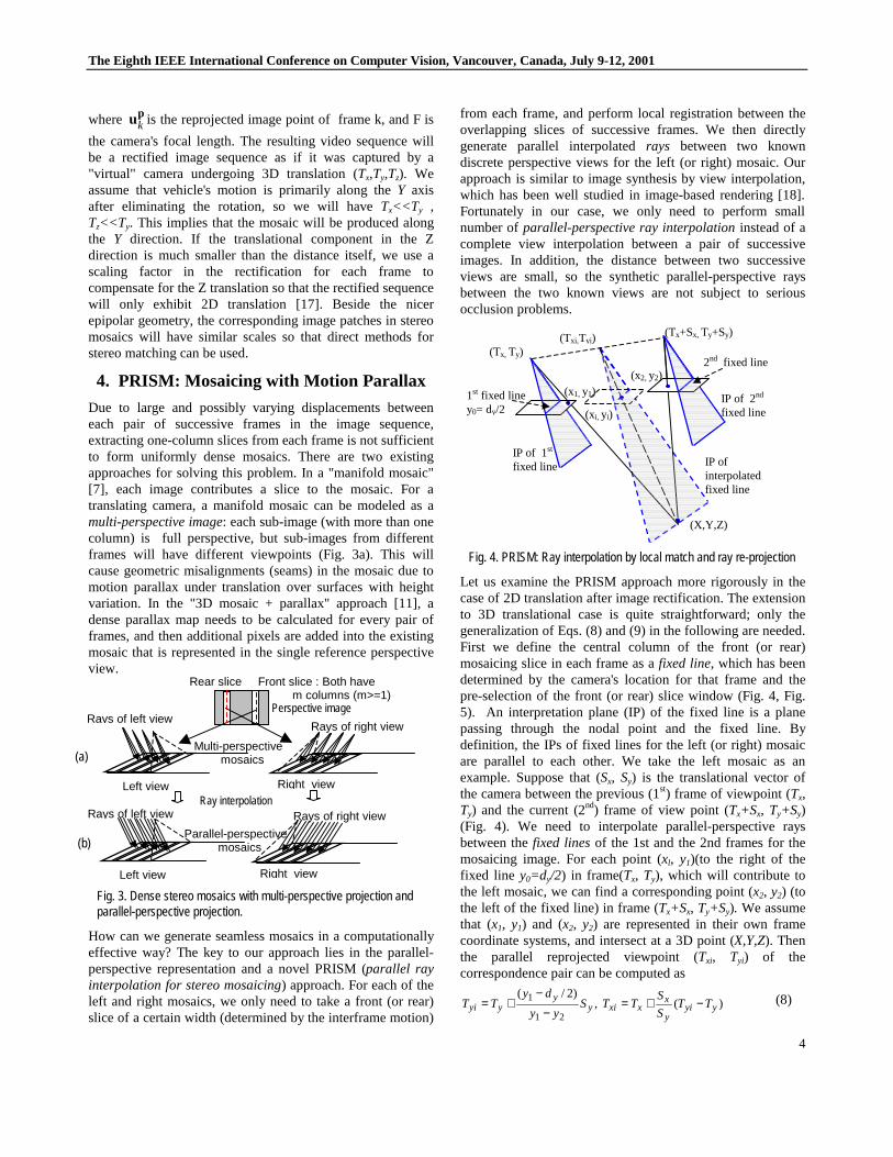
Fig. 4. PRISM: Ray interpolation by local match and ray re-projection
Let us examine the PRISM approach more rigorously in thecase of 2D translation after image rectification. The extensionto 3D translational case is quite straightforward; only thegeneralization of Eqs. (8) and (9) in the following are needed.First we define the central column of the front (or rear)mosaicing slice in each frame as afixed line, which has beendetermined by the camera's location for that frame and thepre-selection of the front (or rear) slice window (Fig. 4, Fig.5). An interpretation plane (IP) of the fixed line is a planepassing through the nodal point and the fixed line. Bydefinition, the IPs of fixed lines for the left (or right) mosaicare parallel to each other. We take the left mosaic as anexample. Suppose that (Sx, Sy) is the translational vector ofthe camera between the previous (1st) frame of viewpoint (Tx,Ty) and the current (2nd) frame of view point (Tx+Sx, Ty+Sy)(Fig. 4). We need to interpolate parallel-perspective raysbetween thefixed linesof the 1st and the 2nd frames for themosaicing image. For each point (xl, y1)(to the right of thefixed line y0=dy/2) in frame(Tx, Ty), which will contribute tothe left mosaic, we can find a corresponding point (x2, y2) (tothe left of the fixed line) in frame (Tx+Sx, Ty+Sy). We assumethat (x1, y1) and (x2, y2) are represented in their own framecoordinate systems, and intersect at a 3D point (X,Y,Z). Thenthe parallel reprojected viewpoint (Txi, Tyi) of thecorrespondence pair can be computed as
)(,)2/(
21
1yyi
y
xxxiy
yyyi TT
S
STTS
yy
dyTT −+=
−−
+= (8)
(Txi,Tyi)
(xi, yi)
IP ofinterpolatedfixed line
(Tx+Sx, Ty+Sy)
(x2, y2)
IP of 2nd
fixed line
(Tx, Ty)
(x1, y1)
IP of 1st
fixed line
(X,Y,Z)
1st fixed liney0= dy/2
2nd fixed line
Front slice : Both havem columns (m>=1)
Rear slice
Perspective image
Multi-perspectivemosaics
Parallel-perspectivemosaics
Rays of left view
Left view
Rays of right view
Right view
Rays of right view
Right view
Rays of left view
Left view
Ray interpolation
(a)
(b)
The Eighth IEEE International Conference on Computer Vision, Vancouver, Canada, July 9-12,2001
5
whereTyi is calculated in a synthetic IP that passes throughthe point (X,Y,Z) and isparallel to the IPs of the fixed linesof the first and second frames.Txi is calculated in a way suchthat all the viewpoints between (Tx,Ty) and (Tx+Sx, Ty+Sy) liein a straight line. The mosaicing coordinates of theinterpolated ray from this pair are
2),
2( 11
yyii
y
y
xxii
dty
dy
S
Sxtx +=−−+= (9)
where (txi ,tyi)=(F Txi / H, F Tyi / H) is the "scaled" viewpointof the interpolated IP that includes the ray.
We have noticed that view interpolation has been suggestedto generating seamless 2D mosaics under motion parallax [9].The authors noted that in order to overcome the parallaxproblems, intermediate images could be syntheticallygenerated between two original frames, and thus narrowerstrips used. Our work is different from theirs in two aspects.First, our approach isdirect and much more efficient. We donot need to generate many new images between each pair oforiginal frames. Instead we directly generate interpolated raysfor the parallel-perspective mosaics from only two slices of apair of successive frames. Second, we proposed to stitch twoimages in the middle of the two fixed lines and to considerthe occluding problem so that views of points in the originalimages are as close as possible to the rays of the finalmosaics. These issues will be further discussed in the nexttwo sections.
5. A Fast PRISM Algorithm
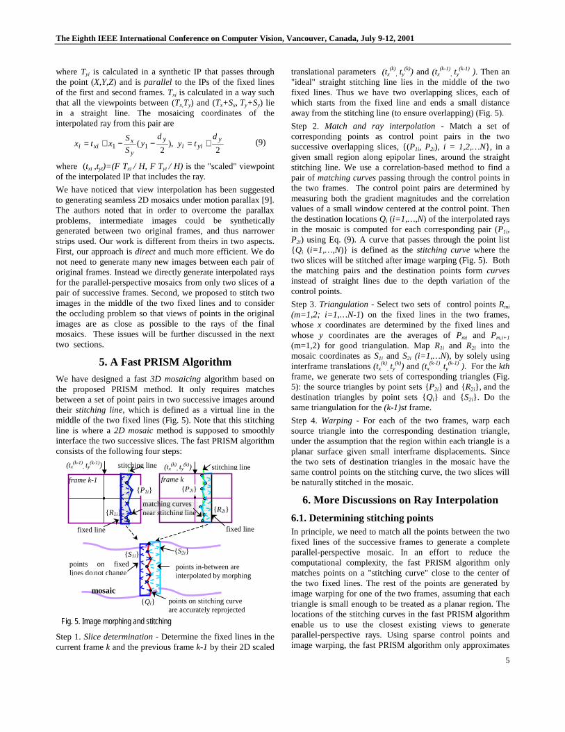
We have designed a fast3D mosaicingalgorithm based onthe proposed PRISM method. It only requires matchesbetween a set of point pairs in two successive images aroundtheir stitching line, which is defined as a virtual line in themiddle of the two fixed lines (Fig. 5). Note that this stitchingline is where a2D mosaicmethod is supposed to smoothlyinterface the two successive slices. The fast PRISM algorithmconsists of the following four steps:
Fig. 5. Image morphing and stitching
Step 1.Slice determination- Determine the fixed lines in thecurrent framek and the previous framek-1 by their 2D scaled
translational parameters(tx(k)
, ty(k)) and (tx
(k-1), ty
(k-1) ). Then an"ideal" straight stitching line lies in the middle of the twofixed lines. Thus we have two overlapping slices, each ofwhich starts from the fixed line and ends a small distanceaway from the stitching line (to ensure overlapping) (Fig. 5).
Step 2. Match and ray interpolation -Match a set ofcorresponding points as control point pairs in the twosuccessive overlapping slices, {(P1i, P2i), i = 1,2,…N}, in agiven small region along epipolar lines, around the straightstitching line. We use a correlation-based method to find apair of matching curvespassing through the control points inthe two frames. The control point pairs are determined bymeasuring both the gradient magnitudes and the correlationvalues of a small window centered at the control point. Thenthe destination locationsQi (i=1,…,N) of the interpolated raysin the mosaic is computed for each corresponding pair (P1i,P2i) using Eq. (9). A curve that passes through the point list{ Qi (i=1,…,N)} is defined as thestitching curvewhere thetwo slices will be stitched after image warping (Fig. 5). Boththe matching pairs and the destination points formcurvesinstead of straight lines due to the depth variation of thecontrol points.
Step 3.Triangulation - Select two sets of control pointsRmi
(m=1,2; i=1,…N-1) on the fixed lines in the two frames,whosex coordinates are determined by the fixed lines andwhose y coordinates are the averages ofPmi and Pm,i+1
(m=1,2) for good triangulation. MapR1i and R2i into themosaic coordinates asS1i and S2i (i=1,…N), by solely usinginterframe translations(tx
(k), ty
(k)) and(tx(k-1)
, ty(k-1) ). For thekth
frame, we generate two sets of corresponding triangles (Fig.5): the source triangles by point sets {P2i} and {R2i}, and thedestination triangles by point sets {Qi} and {S2i}. Do thesame triangulation for the(k-1)stframe.
Step 4.Warping - For each of the two frames, warp eachsource triangle into the corresponding destination triangle,under the assumption that the region within each triangle is aplanar surface given small interframe displacements. Sincethe two sets of destination triangles in the mosaic have thesame control points on the stitching curve, the two slices willbe naturally stitched in the mosaic.
6. More Discussions on Ray Interpolation
6.1. Determining stitching pointsIn principle, we need to match all the points between the twofixed lines of the successive frames to generate a completeparallel-perspective mosaic. In an effort to reduce thecomputational complexity, the fast PRISM algorithm onlymatches points on a "stitching curve" close to the center ofthe two fixed lines. The rest of the points are generated byimage warping for one of the two frames, assuming that eachtriangle is small enough to be treated as a planar region. Thelocations of the stitching curves in the fast PRISM algorithmenable us to use the closest existing views to generateparallel-perspective rays. Using sparse control points andimage warping, the fast PRISM algorithm only approximates
points on stitching curveare accurately reprojected
mosaic
points on fixedlines donot change
points in-between areinterpolated by morphing
{ Qi}
{ S1i} { S2i}
{ R1i}
(tx(k-1)
, ty(k-1)) (tx
(k), ty
(k))
frame kframe k-1
fixed line
stitching linestitching line
fixed line
matching curvesnear stitching line { R2i}
{ P1i} { P2i}
The Eighth IEEE International Conference on Computer Vision, Vancouver, Canada, July 9-12,2001
6
the parallel-perspective geometry in stereo mosaics. However,the proposed PRISM approach can be implemented to usemore feature points ( thus smaller triangles) in theoverlapping slices so that each triangle really covers a planarpatch or a patch that is visually indistinguishable from aplanar patch. Further experiments are underway.
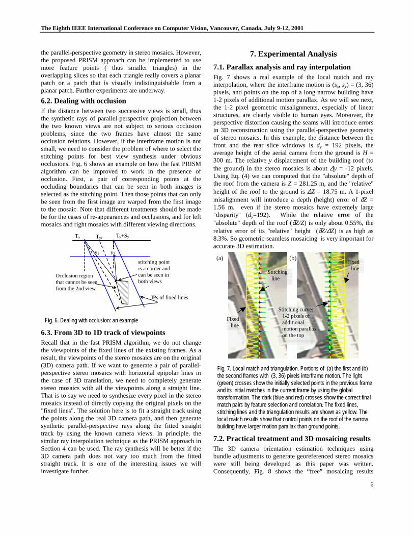
6.2. Dealing with occlusionIf the distance between two successive views is small, thusthe synthetic rays of parallel-perspective projection betweenthe two known views are not subject to serious occlusionproblems, since the two frames have almost the sameocclusion relations. However, if the interframe motion is notsmall, we need to consider the problem of where to select thestitching points for best view synthesis under obviousocclusions. Fig. 6 shows an example on how the fast PRISMalgorithm can be improved to work in the presence ofocclusion. First, a pair of corresponding points at theoccluding boundaries that can be seen in both images isselected as the stitching point. Then those points that can onlybe seen from the first image are warped from the first imageto the mosaic. Note that different treatments should be madebe for the cases of re-appearances and occlusions, and for leftmosaics and right mosaics with different viewing directions.
Fig. 6. Dealing with occlusion: an example
6.3. From 3D to 1D track of viewpointsRecall that in the fast PRISM algorithm, we do not changethe viewpoints of the fixed lines of the existing frames. As aresult, the viewpoints of the stereo mosaics are on the original(3D) camera path. If we want to generate a pair of parallel-perspective stereo mosaics with horizontal epipolar lines inthe case of 3D translation, we need to completely generatestereo mosaics with all the viewpoints along a straight line.That is to say we need to synthesize every pixel in the stereomosaics instead of directly copying the original pixels on the"fixed lines". The solution here is to fit a straight track usingthe points along the real 3D camera path, and then generatesynthetic parallel-perspective rays along the fitted straighttrack by using the known camera views. In principle, thesimilar ray interpolation technique as the PRISM approach inSection 4 can be used. The ray synthesis will be better if the3D camera path does not vary too much from the fittedstraight track. It is one of the interesting issues we willinvestigate further.
7. Experimental Analysis
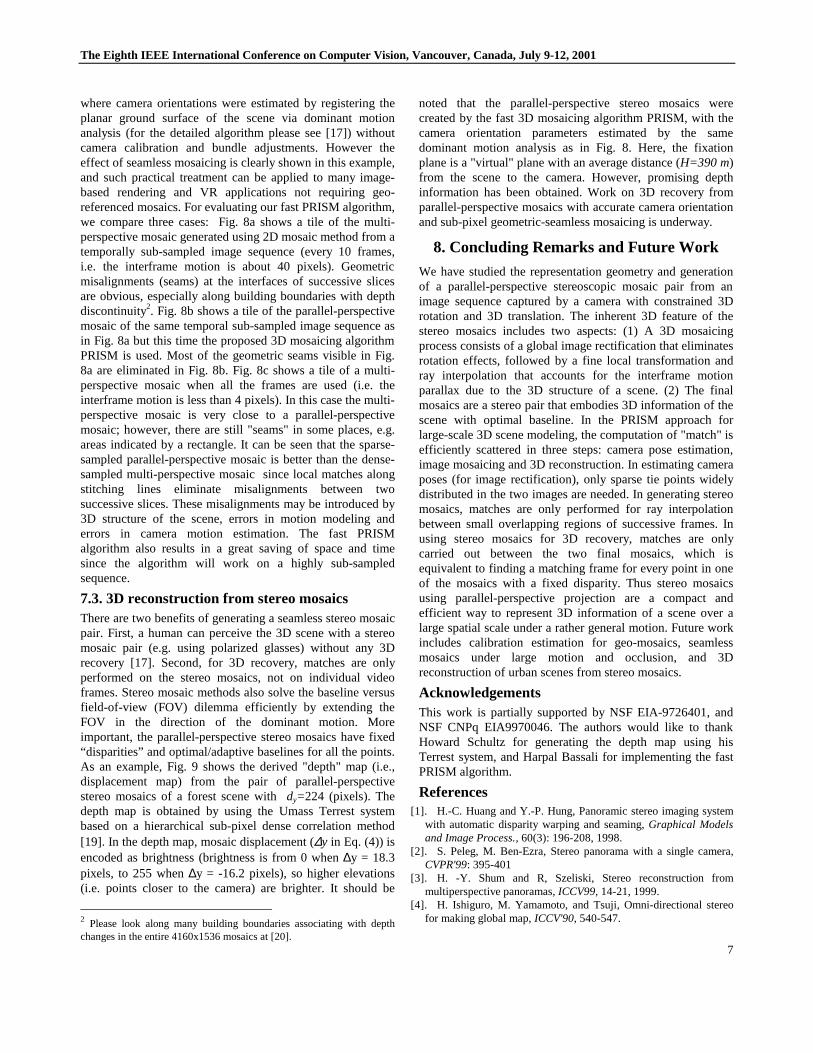
7.1. Parallax analysis and ray interpolationFig. 7 shows a real example of the local match and rayinterpolation, where the interframe motion is (sx, sy) = (3, 36)pixels, and points on the top of a long narrow building have1-2 pixels of additional motion parallax. As we will see next,the 1-2 pixel geometric misalignments, especially of linearstructures, are clearly visible to human eyes. Moreover, theperspective distortion causing the seams will introduce errorsin 3D reconstruction using the parallel-perspective geometryof stereo mosaics. In this example, the distance between thefront and the rear slice windows isdy = 192 pixels, theaverage height of the aerial camera from the ground isH =300 m. The relativey displacement of the building roof (tothe ground) in the stereo mosaics is about∆y = -12 pixels.Using Eq. (4) we can computed that the "absolute" depth ofthe roof from the camera isZ = 281.25 m, and the "relative"height of the roof to the ground is∆Z = 18.75 m. A 1-pixelmisalignment will introduce a depth (height) error ofδZ =1.56 m, even if the stereo mosaics have extremely large"disparity" (dy=192). While the relative error of the"absolute" depth of the roof (δZ/Z) is only about 0.55%, therelative error of its "relative" height (δZ/∆Z) is as high as8.3%. So geometric-seamless mosaicing is very important foraccurate 3D estimation.
Fig. 7. Local match and triangulation. Portions of (a) the first and (b)the second frames with (3, 36) pixels interframe motion. The light(green) crosses show the initially selected points in the previous frameand its initial matches in the current frame by using the globaltransformation. The dark (blue and red) crosses show the correct finalmatch pairs by feature selection and correlation. The fixed lines,stitching lines and the triangulation results are shown as yellow. Thelocal match results show that control points on the roof of the narrowbuilding have larger motion parallax than ground points.
7.2. Practical treatment and 3D mosaicing resultsThe 3D camera orientation estimation techniques usingbundle adjustments to generate georeferenced stereo mosaicswere still being developed as this paper was written.Consequently, Fig. 8 shows the “free” mosaicing results
y1
Ty Ty+SyTyi
y2
stitching pointis a corner andcan be seen inboth views
Occlusion regionthat cannot be seenfrom the 2nd view
IPs of fixed lines
Fixedline
Stitchingline
(a)Fixed
line
Stitching curve:1-2 pixels ofadditionalmotion parallaxon the top
(b)
The Eighth IEEE International Conference on Computer Vision, Vancouver, Canada, July 9-12,2001
7
where camera orientations were estimated by registering theplanar ground surface of the scene via dominant motionanalysis (for the detailed algorithm please see [17]) withoutcamera calibration and bundle adjustments. However theeffect of seamless mosaicing is clearly shown in this example,and such practical treatment can be applied to many image-based rendering and VR applications not requiring geo-referenced mosaics. For evaluating our fast PRISM algorithm,we compare three cases: Fig. 8a shows a tile of the multi-perspective mosaic generated using 2D mosaic method from atemporally sub-sampled image sequence (every 10 frames,i.e. the interframe motion is about 40 pixels). Geometricmisalignments (seams) at the interfaces of successive slicesare obvious, especially along building boundaries with depthdiscontinuity2. Fig. 8b shows a tile of the parallel-perspectivemosaic of the same temporal sub-sampled image sequence asin Fig. 8a but this time the proposed 3D mosaicing algorithmPRISM is used. Most of the geometric seams visible in Fig.8a are eliminated in Fig. 8b. Fig. 8c shows a tile of a multi-perspective mosaic when all the frames are used (i.e. theinterframe motion is less than 4 pixels). In this case the multi-perspective mosaic is very close to a parallel-perspectivemosaic; however, there are still "seams" in some places, e.g.areas indicated by a rectangle. It can be seen that the sparse-sampled parallel-perspective mosaic is better than the dense-sampled multi-perspective mosaic since local matches alongstitching lines eliminate misalignments between twosuccessive slices. These misalignments may be introduced by3D structure of the scene, errors in motion modeling anderrors in camera motion estimation. The fast PRISMalgorithm also results in a great saving of space and timesince the algorithm will work on a highly sub-sampledsequence.
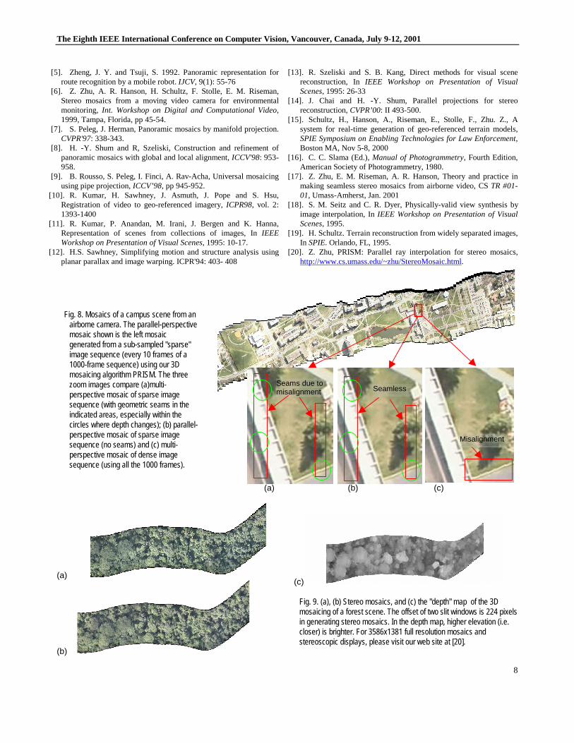
7.3. 3D reconstruction from stereo mosaicsThere are two benefits of generating a seamless stereo mosaicpair. First, a human can perceive the 3D scene with a stereomosaic pair (e.g. using polarized glasses) without any 3Drecovery [17]. Second, for 3D recovery, matches are onlyperformed on the stereo mosaics, not on individual videoframes. Stereo mosaic methods also solve the baseline versusfield-of-view (FOV) dilemma efficiently by extending theFOV in the direction of the dominant motion. Moreimportant, the parallel-perspective stereo mosaics have fixed“disparities” and optimal/adaptive baselines for all the points.As an example, Fig. 9 shows the derived "depth" map (i.e.,displacement map) from the pair of parallel-perspectivestereo mosaics of a forest scene withdy=224 (pixels). Thedepth map is obtained by using the Umass Terrest systembased on a hierarchical sub-pixel dense correlation method[19]. In the depth map, mosaic displacement (∆y in Eq. (4)) isencoded as brightness (brightness is from 0 when∆y = 18.3pixels, to 255 when∆y = -16.2 pixels), so higher elevations(i.e. points closer to the camera) are brighter. It should be
2 Please look along many building boundaries associating with depthchanges in the entire 4160x1536 mosaics at [20].
noted that the parallel-perspective stereo mosaics werecreated by the fast 3D mosaicing algorithm PRISM, with thecamera orientation parameters estimated by the samedominant motion analysis as in Fig. 8. Here, the fixationplane is a "virtual" plane with an average distance (H=390 m)from the scene to the camera. However, promising depthinformation has been obtained. Work on 3D recovery fromparallel-perspective mosaics with accurate camera orientationand sub-pixel geometric-seamless mosaicing is underway.
8. Concluding Remarks and Future Work
We have studied the representation geometry and generationof a parallel-perspective stereoscopic mosaic pair from animage sequence captured by a camera with constrained 3Drotation and 3D translation. The inherent 3D feature of thestereo mosaics includes two aspects: (1) A 3D mosaicingprocess consists of a global image rectification that eliminatesrotation effects, followed by a fine local transformation andray interpolation that accounts for the interframe motionparallax due to the 3D structure of a scene. (2) The finalmosaics are a stereo pair that embodies 3D information of thescene with optimal baseline. In the PRISM approach forlarge-scale 3D scene modeling, the computation of "match" isefficiently scattered in three steps: camera pose estimation,image mosaicing and 3D reconstruction. In estimating cameraposes (for image rectification), only sparse tie points widelydistributed in the two images are needed. In generating stereomosaics, matches are only performed for ray interpolationbetween small overlapping regions of successive frames. Inusing stereo mosaics for 3D recovery, matches are onlycarried out between the two final mosaics, which isequivalent to finding a matching frame for every point in oneof the mosaics with a fixed disparity. Thus stereo mosaicsusing parallel-perspective projection are a compact andefficient way to represent 3D information of a scene over alarge spatial scale under a rather general motion. Future workincludes calibration estimation for geo-mosaics, seamlessmosaics under large motion and occlusion, and 3Dreconstruction of urban scenes from stereo mosaics.
AcknowledgementsThis work is partially supported by NSF EIA-9726401, andNSF CNPq EIA9970046. The authors would like to thankHoward Schultz for generating the depth map using hisTerrest system, and Harpal Bassali for implementing the fastPRISM algorithm.
References[1]. H.-C. Huang and Y.-P. Hung, Panoramic stereo imaging system
with automatic disparity warping and seaming,Graphical Modelsand Image Process., 60(3): 196-208, 1998.
[2]. S. Peleg, M. Ben-Ezra, Stereo panorama with a single camera,CVPR'99: 395-401
[3]. H. -Y. Shum and R, Szeliski, Stereo reconstruction frommultiperspective panoramas,ICCV99, 14-21, 1999.
[4]. H. Ishiguro, M. Yamamoto, and Tsuji, Omni-directional stereofor making global map,ICCV'90, 540-547.
The Eighth IEEE International Conference on Computer Vision, Vancouver, Canada, July 9-12,2001
8
[5]. Zheng, J. Y. and Tsuji, S.1992. Panoramic representation forroute recognition by a mobile robot.IJCV, 9(1): 55-76
[6]. Z. Zhu, A. R. Hanson, H. Schultz, F. Stolle, E. M. Riseman,Stereo mosaics from a moving video camera for environmentalmonitoring, Int. Workshop on Digital and Computational Video,1999, Tampa, Florida, pp 45-54.
[7]. S. Peleg, J. Herman, Panoramic mosaics by manifold projection.CVPR'97: 338-343.
[8]. H. -Y. Shum and R, Szeliski, Construction and refinement ofpanoramic mosaics with global and local alignment,ICCV'98: 953-958.
[9]. B. Rousso, S. Peleg, I. Finci, A. Rav-Acha, Universal mosaicingusing pipe projection,ICCV’98, pp 945-952.
[10]. R. Kumar, H. Sawhney, J. Asmuth, J. Pope and S. Hsu,Registration of video to geo-referenced imagery,ICPR98, vol. 2:1393-1400
[11]. R. Kumar, P. Anandan, M. Irani, J. Bergen and K. Hanna,Representation of scenes from collections of images, InIEEEWorkshop on Presentation of Visual Scenes, 1995: 10-17.
[12]. H.S. Sawhney, Simplifying motion and structure analysis usingplanar parallax and image warping. ICPR'94: 403- 408
[13]. R. Szeliski and S. B. Kang, Direct methods for visual scenereconstruction, InIEEE Workshop on Presentation of VisualScenes,1995: 26-33
[14]. J. Chai and H. -Y. Shum, Parallel projections for stereoreconstruction,CVPR’00: II 493-500.
[15]. Schultz, H., Hanson, A., Riseman, E., Stolle, F., Zhu. Z., Asystem for real-time generation of geo-referenced terrain models,SPIE Symposium on Enabling Technologies for Law Enforcement,Boston MA, Nov 5-8, 2000
[16]. C. C. Slama (Ed.),Manual of Photogrammetry, Fourth Edition,American Society of Photogrammetry, 1980.
[17]. Z. Zhu, E. M. Riseman, A. R. Hanson, Theory and practice inmaking seamless stereo mosaics from airborne video, CSTR #01-01, Umass-Amherst, Jan. 2001
[18]. S. M. Seitz and C. R. Dyer, Physically-valid view synthesis byimage interpolation, InIEEE Workshop on Presentation of VisualScenes,1995.
[19]. H. Schultz. Terrain reconstruction from widely separated images,In SPIE. Orlando, FL,1995.
[20]. Z. Zhu, PRISM: Parallel ray interpolation for stereo mosaics,http://www.cs.umass.edu/~zhu/StereoMosaic.html.
(a) (b) (c)
(a)
(b)
(c)
Fig. 9. (a), (b) Stereo mosaics, and (c) the "depth" map of the 3Dmosaicing of a forest scene. The offset of two slit windows is 224 pixelsin generating stereo mosaics. In the depth map, higher elevation (i.e.closer) is brighter. For 3586x1381 full resolution mosaics andstereoscopic displays, please visit our web site at [20].
Fig. 8. Mosaics of a campus scene from anairborne camera. The parallel-perspectivemosaic shown is the left mosaicgenerated from a sub-sampled "sparse"image sequence (every 10 frames of a1000-frame sequence) using our 3Dmosaicing algorithm PRISM. The threezoom images compare (a)multi-perspective mosaic of sparse imagesequence (with geometric seams in theindicated areas, especially within thecircles where depth changes); (b) parallel-perspective mosaic of sparse imagesequence (no seams) and (c) multi-perspective mosaic of dense imagesequence (using all the 1000 frames).
Seams due tomisalignment
Misalignment
Seamless