parameter-invariant actuator fault diagnostics in cyber...
TRANSCRIPT
Parameter-Invariant Actuator Fault Diagnostics
in Cyber-Physical Systems with Application to
Building Automation
James Weimer1, José Araujo2, Mani Amoozadeh2, Seyed Alireza Ahmadi2,Henrik Sandberg2, and Karl Henrik Johansson2
1 Department of Computer and Information SciencesSchool of Engineering and Applied Sciences
University of PennsylvaniaPhiladelphia, PA 19104, [email protected]
2 ACCESS Linnaeus Centre, School of Electrical EngineeringKTH Royal Institute of Technology
Stockholm, Sweden 10044{araujo,maniam,saahmadi,hsan,kalle}@kth.se
Abstract. This paper introduces a robust method for performing activeactuator fault detection and diagnostics (FDD) in heating ventilation andair conditioning (HVAC) systems. The proposed actuator FDD strategy,for testing whether an actuator is stuck in a given position, is designed onusing an invariant hypothesis testing approach and is an improvementof a previous strategy that employed an adaptive detection strategy.The parameter-invariant detector is formulated to provide a constantdetection performance, invariant to unknown building parameters, andit is described how this approach can replace the adaptive detector inthe previous work. A closed-loop experimental HVAC testbed at theKTH Royal Institute of Technology campus in Stockholm, Sweden isintroduced and employed to evaluate the parameter-invariant detector.
Keywords: building automation, fault detection and diagnostics (FDD),invariant hypothesis testing, heating ventilation and air conditioning(HVAC) systems
1 Introduction
Heating, ventilation and cooling (HVAC) are known to be the largest consumer ofenergy in buildings, accounting for 43% of U.S. residential energy consumption.The design of energy-efficient HVAC systems has therefore become a worldwideresearch priority. In the U.S. and U.K., buildings consume nearly 40% and 47%of the national energy, respectively [28, 27]. Due to this high usage, there existsa high potential for energy consumption improvement, which has thrust HVACsystem operations to the forefront of world-wide research agendas. Recently,several researchers have studied how to improve the control of HVAC systems by
2 Authors Suppressed Due to Excessive Length
deploying more embedded sensors to monitor temperature, humidity, and CO2
levels [17], using information about occupant behavior [18, 11, 4], and improvingthe modeling and control approaches [21, 19, 25, 20, 24, 23, 5].
To achieve an increase in building efficiency requires an increase in the num-ber of sensors and actuators deployed. While the inclusion of these smart devicesenables low cost and environmentally friendly building energy management sys-tems, undetected sensor and actuator failures can result in poor temperatureand air quality management. Moreover, HVAC Fault Detection and Diagnostic(FDD) schemes which result in unpredictable or erratic performance can deterbuilding managers from investigating potential failures. For these reasons, tech-nological development of FDD schemes tailored for HVAC systems is paramountand has received much research interest in the recent years [16, 12, 10, 14].
The study of HVAC FDD systems has only been investigated since the late1980s, with a particular interest in identifying low-cost, timely, and accuratemethods for detecting actuator faults. A thorough review of approaches to HVACactuator fault detection, diagnostics, and prognostics prior to 2006 is providedin [16, 15]. In general, approaches to HVAC actuator fault detection can be clas-sified as either hardware-based or software-based solutions [16]. The hardware-based solutions introduce additional smart components strictly for the purposesof actuator fault detection and provide accurate detection capabilities; however,hardware solutions are far more expensive to both deploy and maintain thansoftware-based approaches, and are much more difficult to reconfigure with theintroduction of additional smart-actuator devices [15]. Moreover, the inclusionof additional hardware has the added drawback of further increasing the com-plexity of the HVAC system itself. Software-based actuator FDD approaches areattractive in theory, but suffer from either a reliance on unknown (and difficultto learn) physical models or system-specific detector design specifications [12,16, 15, 14].
Modern building energy management systems require accurate HVAC controlto minimize energy usage while maintaining an acceptable level of comfort forthe building occupants. Thus, actuator fault detection is necessary to ensureproper building operation as HVAC systems are subject to various aging andoperation errors which can lead to hardware malfunction. A common failure inHVAC systems occurs when the actuator "sticks" and no longer changes its setpoint, despite controller requests. This type of actuator failure can occur in anyposition. For example, a valve can be stuck fully open, fully shut, or at anyintermediate setting. Additionally, being able to isolate specific actuator failuresis paramount to performing timely maintenance.
In [1], an HVAC FDD architecture is introduced that utilizes a fast-decidingsteady-state detector and an adaptive model-based detector that are appliedto a cooling vent fault detection. The primary difference between the previousapproaches, and other model-based software approaches described in [16, 15] isthe use of a two-tiered detection approach containing a distributed quantitativemodel-based approach and a distributed qualitative model-based approach toprovide quick inference when an actuator is working and provide accurate de-
Title Suppressed Due to Excessive Length 3
tection when an actuator has failed. Logic indicates that in the event that anactuator is working, applying a significant change in the actuation input resultsin a measurable change in the temperature. Under this reasoning, the steady-state detector quickly identifies operational actuators, but it tends to result ina high probability of false alarm when the actuator is operational, but its effecton the temperature is dampened (i.e. a window is open such that the tempera-ture is not significantly affected through actuation). To reduce the probabilityof false alarm in the HVAC FDD strategy, an adaptive model-based detector isemployed based on a first-order building thermal dynamic model. The model-based detector utilizes a history of measurements to estimate the unknown modelparameters, then employs the estimated model to detect faults. While the adap-tive model-based detector was shown to have a significantly lower probability offalse alarm in comparison to the steady-state detector, the resulting performancewas highly variant depending on the environmental variables (windows open vs.closed, outside air temperature, etc.) which directly affected the underlying pa-rameter estimation. This sporadic false alarm behavior is undesirable in HVACFDD schemes as it leads to mistrust by building managers.
In this work, the primary contribution is a parameter-invariant detector (toreplace the previously developed model-based detector [1]) that maintains aconstant probability of miss across all operating conditions of the HVAC FDDstrategy. Additionally, the parameter-invariant detector does not require fullmodel knowledge as it only relies on the structure of a simplified thermodynamicmodel. The fact that the detector not only detects, but also isolates individualactuator failures is an added contribution. A second contribution of this work isthe introduction and description of a closed-loop HVAC monitoring and controlsystem that interfaces directly with the KTH Royal Institute of TechnologyHVAC system, located in Stockholm, Sweden. An evaluation of the system isprovided using the experimental testbed that illustrates the performance of theparameter-invariant detector.
In terms of notation, we use plain lower case italic fonts to indicate scalarsor functions with scalar range, bold lower case italic fonts to indicate vectors orfunctions with vector range, and plain upper case italic fonts to indicate matrices.We also use ⊗ to denote Kronecker products, and ei,j to denote the elementaryvector of dimension i consisting of all zeros with a single unit entry in the j-thposition.
In the following section, we motivate and formulate the actuator FDD prob-lem for building automation. Section 3 introduces the parameter-invariant detec-tor and a novel diagnostic input design. The KTH Royal Institute of TechnologyHVAC test bed is described in section 4 and an evaluation of the parameter-invariant detector is provided in section 5. The concluding section provides dis-cussion and insight into future work.
4 Authors Suppressed Due to Excessive Length
2 Problem Formulation
In this section, we formulate a distributed actuator fault detection problem forHVAC systems. While precise thermal modeling of buildings is an ongoing science[6, 8], it has repeatedly been experimentally demonstrated that a first principleof the thermal dynamics model is accurate for zone-level temperature evolutionin buildings [26, 13, 9, 3]. We consider a building with M interconnected temper-ature zones for which there exists an underlying interconnection graph, G(V , E),between the M zones, where V := {1, . . . ,M} is the vertex set, with i ∈ Vcorresponding to zone i, and E ⊆ V × V is the edge set of the graph. The undi-rected edge {i, j} is incident on vertices i and j if zones i and j interact. Theneighborhood of zone i, Ni, is defined as
Ni :={
j ∈ V∣
∣ {i, j} ∈ E}
(1)
A generic thermodynamic model of the zone interactions is provided through aspatial and temporal discretization of the first-order heat equation as
xj(k + 1) = xj(k) +mj
∑
i∈Nj
aji
(
xi(k)− xj(k))
+ bjdj(k) + wj(k)
yj(k) = xj(k) + vj(k)
(2)
where:
– k = 0, . . . , T is the time index (T even for notational simplicity3);– j = 1, . . . ,M is the zone index;– the temperature xj(k)’s, measurements yj(k)’s and actuator inputs dj(k)’s
are scalar;– mj is the volume of air contained in zone j;– aji = aij ∈ R and bj ∈ R denote respectively the gains between xi(k) and
xj(k + 1), and between dj(k) and xj(k + 1);– wj(k), vj(k) ∈ R are uncorrelated i.i.d. Gaussian process noise and measure-
ment noise with moments
E [wj(k)] = χj,w E [vj(k)] = χj,v = 0,
E
[
(
wj(k)− χj,w
)2]
= σ2j,w E
[
(
vj(k)− χj,v
)2]
= σ2j,v.
We note that in the event of a zone containing multiple actuators and a singlesensor, actuator FDD can be performed by allowing only a single actuator tovary. In doing this, the stationary actuators are effectively lumped into the pro-cess noise mean since it is a constant input into the thermal model. To compact
3 For ease of notation and without loss of generality we assume that the availablemeasurements are over a given period whose length is fixed ex ante.
Title Suppressed Due to Excessive Length 5
the notation we let, for j = 1, . . . ,M ,
A :=[
αij
]
αij :=
1−mj
∑
n∈Nj
anj if i = j
mjaij if i ∈ Nj , i 6= j
0 otherwise
B := diag [b1, . . . , bM ]
yj := [yj(0), . . . , yj(T )]⊤
dj := [dj(0), . . . , dj(T )]⊤.
Additionally, we consider the following quantities, assuming Nj = {i1, . . . , iJ} isthe sorted list of neighboring zones of zone j. Then
~αj := [αi1j , . . . , αiJ j ]⊤,
~yj(k) := [yi1(k), . . . , yiJ (k)]⊤,
~yj :=[
yTi1, . . . ,yT
iJ
]⊤,
where, ~yj(k) is the set of the measurements of agent j and its neighbors (sortedlexicographically) at time k, while ~yj is the set of all the measurements of agentj and its neighbors (again sorted lexicographically).
Consider then a specific zone ℓ ∈ {1, . . . ,M}, containing an actuator. Thestructure of the actual actuator input dℓ is assumed to be as follows:
– uℓ :=[
uℓ(0), . . . , uℓ(T )]⊤
is a desired and known actuation signal;– θℓ ∈ R is an unknown (but constant) input.
Thendℓ = θℓ1+ µℓuℓ (3)
where the binary scalar µℓ ∈ {0, 1} is an unknown test parameter indicatingwhether the actuation signal is present (µℓ = 1) or absent (µℓ = 0).
We summarize the available information for detecting an actuator failure inzone ℓ as follows:
Assumption 1 Available information:
– the time-series measurements ~yℓ
– the local desired actuation signal uℓ;– the local zone air-volume weight mℓ;– when an actuator fails, its input to the system remains constant;– the fact that the state dynamics are LTI-Gaussian, constant in time, and
with bℓ 6= 0.
For completeness, we summarize the unavailable information as:

6 Authors Suppressed Due to Excessive Length
Assumption 2 Unavailable information:
– all the time-series measurements except ~yℓ
– all the local desired input signals except uℓ;– all the local weights except mℓ;– the weights A and B;– the moments of the process and measurement noises χj,w, σ2
j,w, σ2j,v, for all
j = 1, . . . ,M ;– the actuation parameters θj and µj for all j = 1, . . . ,M ;– the initial conditions x1(0), . . . , xM (0);– the input signals d1, . . . ,dM .
We then assume the unknown µℓ to be either 0 (actuator ℓ is at fault) or1 (actuator ℓ not at fault) and pose the following binary hypothesis testingproblem:
Assumption 3 Structure of the actuator fault µℓ satisfies either one ofthe two following hypotheses:
H0 (null hypothesis): µℓ = 1 (no fault)H1 (alternative hypothesis): µℓ = 0 (fault)
In words, both hypotheses assume the actual dℓ to be unknown, since θℓis unknown, but with a fixed and known functional structure. H0 additionallyassumes the presence of the known actuation input uℓ. Our aim is the following:develop a distributed test that considers a specific zone ℓ ∈ {1, . . . ,M}, anddecides among the hypotheses H0 vs. H1 in Assumption 3 using only the infor-mation in Assumption 1 and, at the same time, being invariant to the unavailableinformation in Assumption 2. Thus, we state the following problem:
Problem 4Find a test that detects whether zone ℓ has an actuator fault independently
of whether a fault exists at any other zone j 6= ℓ (fault isolation) and mini-mizes the probability of false alarm while maintaining a constant probabilityof detection.
The following section presents a solution to the problem introduced in thissection.
Title Suppressed Due to Excessive Length 7
3 Parameter-Invariant Actuator FDD
In this section, we introduce a distributed HVAC actuator FDD strategy, tailoredfor detecting and isolating whether actuators are stuck in an unknown positionsuch that a constant level of detection is maintained. To achieve this goal, thefollowing subsections introduces a parameter-invariant detector and an actuatordiagnostic input, respectively.
3.1 Parameter-Invariant Detector
In this section, we recall the test developed for distributed detection of inputsin networked systems in [2]. This test, in the context of the HVAC detectionproblem, is designed to minimize the probability of false alarm, subject to aconstraint on the probability of detection. We state the primary result of [2],augmented for the actuation detection problem, in the following lemma:
Lemma 5 A maximally invariant statistic for Problem 4 is
T [zℓ] =z⊤ℓ Pℓzℓ
1
Nℓ − 1z⊤ℓ
(
INℓ− Pℓ
)
zℓ
(4)
with
zℓ := FℓQyℓ
Pℓ :=FℓQuℓu
⊤ℓ Q
⊤F⊤ℓ
u⊤ℓ Q
⊤F⊤ℓ FℓQuℓ
Nℓ :=T
2− ‖Nℓ‖0 − 1
(5)
and where the exploited quantities satisfy
F⊤ℓ Fℓ = IT
2
− ~Yℓ(~Y⊤ℓ~Yℓ)
−1~Y ⊤ℓ
Q = IT2
⊗ [ 0 1 ]
~Yℓ =
~y⊤ℓ (0) 1~y⊤ℓ (2) 1~y⊤ℓ (4) 1
......
~y⊤ℓ (T ) 1
(6)
Applying the maximally invariant statistic, and following the same reasoningas in [2], we write the test for detecting actuator failures as:
8 Authors Suppressed Due to Excessive Length
Corollary 6 A distributed test minimizing the probability of false alarm andproviding a constant probability of missed detection of α for Problem 4 is
φℓ(zℓ) =
{
H0 if Tℓ[zℓ] > F−1
1,Nℓ−1(α)
H1 otherwise(7)
where F−1n,m(α) is the inverse central cumulative F -distribution of dimensions
n and m.
We remark that test (7) can be performed in simultaneously across multiplezones and it is invariant to the non-local measurements. This comes with a price,namely, the test exploits half the measurements for testing (the other half areused to establish invariance). To maximize the performance across this reduceddata set, the following subsection introduces an adaptive actuator diagnosticsignal.
3.2 Diagnostic Input Design
The performance of the detector is significantly affected by the actuation inputdriving the test. In this subsection, and motivated by the performance of theadaptive model-based detector in [1], we design a diagnostic input that attemptsto maximize the divergence of test.
To design the diagnostic actuation input, we observe that the discrete-timedynamics for measurement of the j-th zone can be written as
zj(k) = Gkzj(k) + nj(k)
yj(k) = Czj(k) + vj(k)(8)
where
zj(k) =[
xj(k), mjαTj , bj , χj,w + bjθj
]T
Gk =
1 ~y⊤j (k)− 1
⊤yj(k) µjuj(k) 10 I 0 00 0
⊤ 1 00 0
⊤ 0 1
nj(k) =[
wj(k) +∑
i∈Njαijvi(k), 0
⊤, 0, 0]T
C =[
1 0⊤ 0 0
]
(9)
As a heuristic, we assume (strictly for the purpose of designing an actuationinput) that the true values of αij are equal to the corresponding values pro-vided through zj(k). Under this assumption, the measurements have a Gaussiandistribution, parameterized by µj , written as
fj(yj(k)) =1
√
2π(
CΣk,jC⊤ + σ2j,v
)
exp
{
−1
2
(yj(k)−Cmk,j)2
(CΣk,jCT + σ2j,v)
}
(10)
Title Suppressed Due to Excessive Length 9
where, assuming Σj,n = E
[
nk,jn⊤k,j
]
mk+1,j = (G(k)−Kk,jC)mk,j +Kk,jyj(k)
Σk+1,j = (G(k)−Kk,jC)Σk,jG⊤(k) +Σj,n
Kk,j = G(k)Σk,jC⊤(
CΣk,jC⊤ + σ2
j,v
)−1
(11)
are the mean and covariance of zj(k) and the observer gain, respectively.To identify the actuator input for evaluating the detection problem, we utilize
an information-theoretic approach and choose the actuator input to maximizethe next step Kulbach-Liebner [7] divergence according to
uk = arg max0≤u≤1
−E [lj(yk)] (12)
where lj(yk) is the log-likelihood ratio,
lj(k) = lj(k − 1) + lnfj(yj(k)|µj = 0)
fj(yj(k)|µj = 1). (13)
This approach is common in information theory as it results in the control se-quence that maximizes the next step log-likelihood ratio. Since the log-likelihoodis a convex function of the control sequence, it is maximized at the extreme pointsof the range of the control sequence as denoted as follows
uk =
{
1 if E [lj(k + 1|uj(k) = 1)] > E [lj(k + 1|uj(k) = 0)]0 if E [lj(k + 1|uj(k) = 1)] ≤ E [lj(k + 1|uj(k) = 0)]
(14)
In an HVAC system this equates to either turning the HVAC actuator completelyon or completely off. While this control input is advantageous for fault detectionand diagnostics, it comes at a trade-off with the performance of the HVAC systemsince the control input does not correspond to the optimal building operationset-point.
It will be shown in the experimental evaluation section that the parameter-invariant detector requires significant monitoring periods to accurately determinewhether an actuator has failed. Moreover, fault detection schemes that requirelong monitoring periods may not be necessary to identify a working actuatorif the actuator has a significant effect on the temperature. For this reason, theparameter-invariant detector is best suited to replace the model-based adaptivedetector in the previous work.
4 Experimental Testbed
The KTH Royal Institute of Technology main campus in Stockholm, Swedenconsists of over 45 buildings which house roughly 559 laboratories, 2569 officerooms and 87 lecture halls. The campus has an HVAC system managed by acentralized SCADA system. The SCADA map of the KTH campus is depicted
10 Authors Suppressed Due to Excessive Length
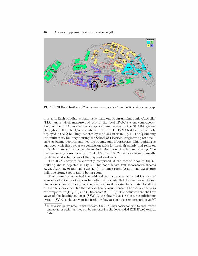
Fig. 1. KTH Royal Institute of Technology campus view from the SCADA system map.
in Fig. 1. Each building is contains at least one Programming Logic Controller(PLC) units which measure and control the local HVAC system components.Each of the PLC units in the campus communicates to the SCADA systemthrough an OPC client/server interface. The KTH HVAC test bed is currentlydeployed in the Q-building (denoted by the black circle in Fig. 1). The Q-buildingis a multi-story building housing the School of Electrical Engineering with mul-tiple academic departments, lecture rooms, and laboratories. This building isequipped with three separate ventilation units for fresh air supply and relies ona district-managed water supply for induction-based heating and cooling. Thefresh air supply takes place from 7 : 00 AM to 4 : 00 PM, and can be set manuallyby demand at other times of the day and weekends.
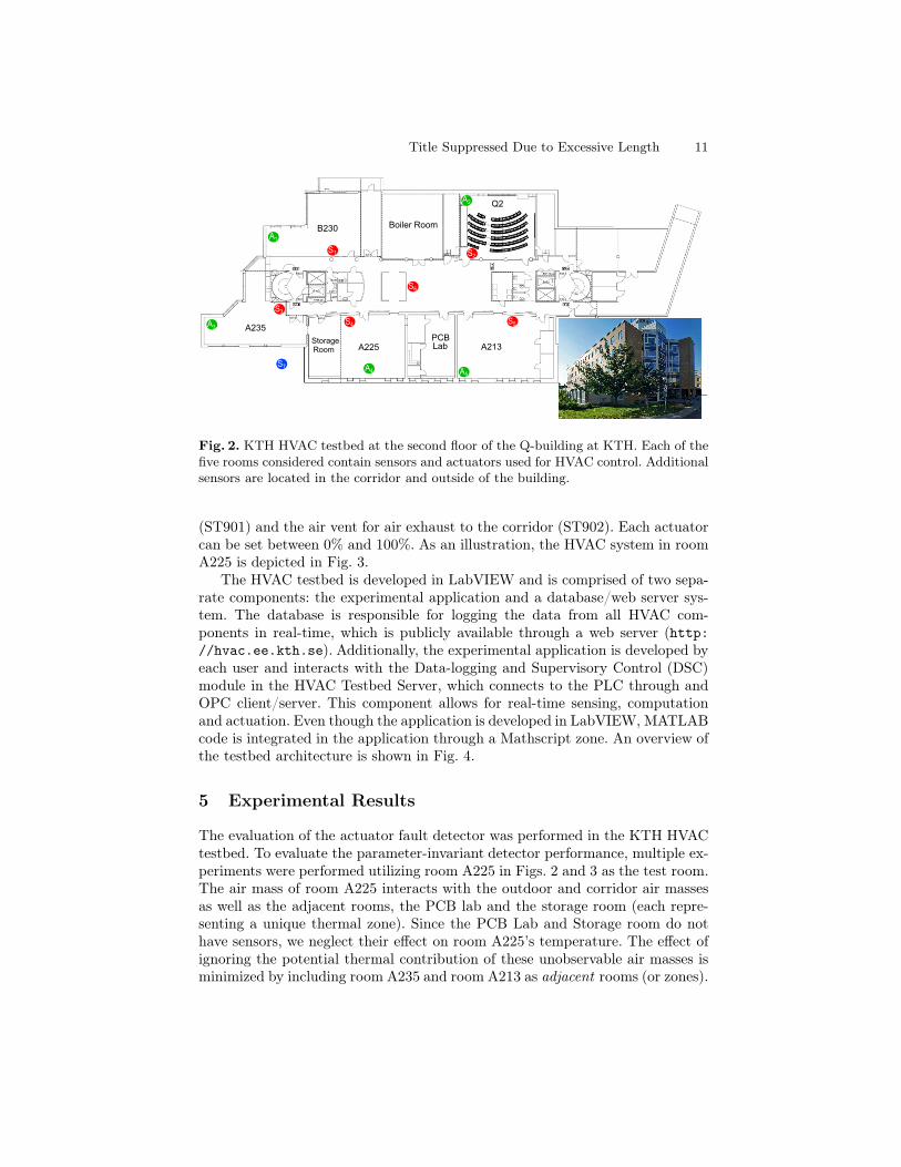
The HVAC testbed is currently comprised of the second floor of the Q-building and is depicted in Fig. 2. This floor houses four laboratories (roomsA225, A213, B230 and the PCB Lab), an office room (A235), the Q2 lecturehall, one storage room and a boiler room.
Each room in the testbed is considered to be a thermal zone and has a set ofsensors and actuators that can be individually controlled. In the figure, the redcircles depict sensor locations, the green circles illustrate the actuator locationsand the blue circle denotes the external temperature sensor. The available sensorsare temperature (GQ101) and CO2 sensors (GT101)4. The actuators are the flowvalve of the heating radiator (SV201), the flow valve for the air conditioningsystem (SV401), the air vent for fresh air flow at constant temperature of 21 ◦C
4 In this section we note, in parentheses, the PLC tags corresponding to each sensorand actuator such that they can be referenced in the downloaded KTH HVAC testbeddata.
Title Suppressed Due to Excessive Length 11
A
A
A3
A4 A5
A2
S2
S5S4
S3
S1
S SS6
S
SS7
A1
A225
A235
A213
B230 Boiler Room
Q2
PCBStorageRoom Lab
Fig. 2. KTH HVAC testbed at the second floor of the Q-building at KTH. Each of thefive rooms considered contain sensors and actuators used for HVAC control. Additionalsensors are located in the corridor and outside of the building.
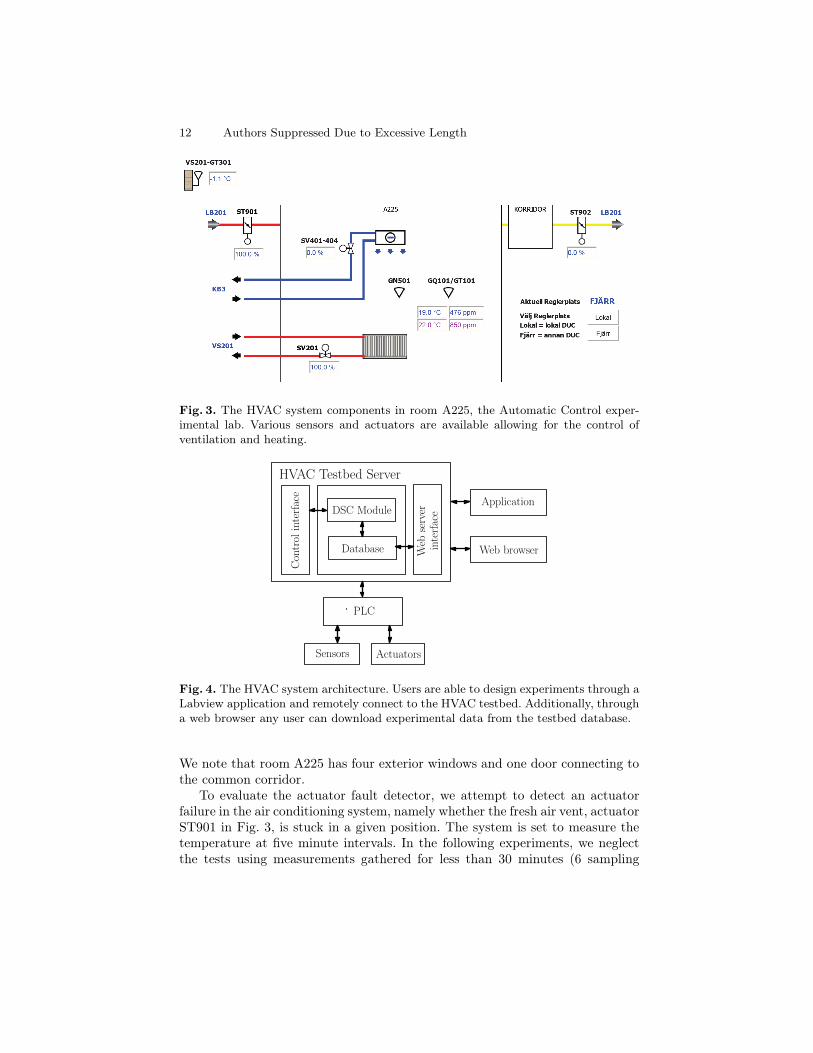
(ST901) and the air vent for air exhaust to the corridor (ST902). Each actuatorcan be set between 0% and 100%. As an illustration, the HVAC system in roomA225 is depicted in Fig. 3.
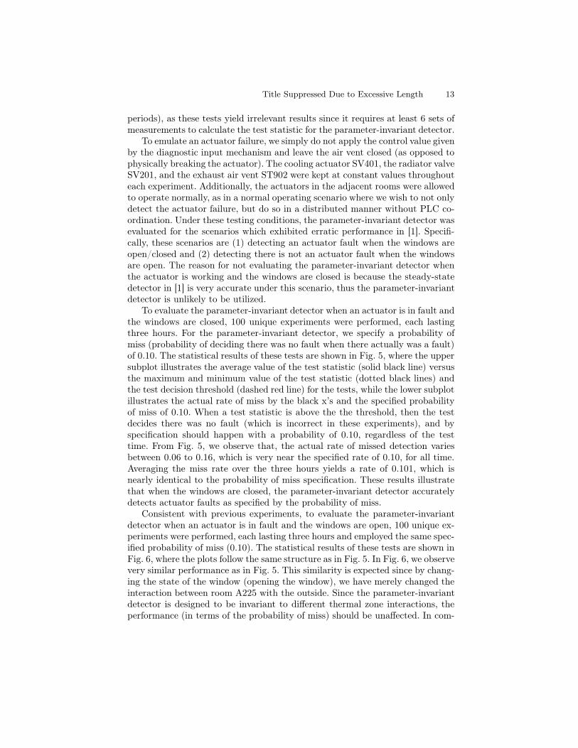
The HVAC testbed is developed in LabVIEW and is comprised of two sepa-rate components: the experimental application and a database/web server sys-tem. The database is responsible for logging the data from all HVAC com-ponents in real-time, which is publicly available through a web server (http://hvac.ee.kth.se). Additionally, the experimental application is developed byeach user and interacts with the Data-logging and Supervisory Control (DSC)module in the HVAC Testbed Server, which connects to the PLC through andOPC client/server. This component allows for real-time sensing, computationand actuation. Even though the application is developed in LabVIEW, MATLABcode is integrated in the application through a Mathscript zone. An overview ofthe testbed architecture is shown in Fig. 4.
5 Experimental Results
The evaluation of the actuator fault detector was performed in the KTH HVACtestbed. To evaluate the parameter-invariant detector performance, multiple ex-periments were performed utilizing room A225 in Figs. 2 and 3 as the test room.The air mass of room A225 interacts with the outdoor and corridor air massesas well as the adjacent rooms, the PCB lab and the storage room (each repre-senting a unique thermal zone). Since the PCB Lab and Storage room do nothave sensors, we neglect their effect on room A225’s temperature. The effect ofignoring the potential thermal contribution of these unobservable air masses isminimized by including room A235 and room A213 as adjacent rooms (or zones).
12 Authors Suppressed Due to Excessive Length
Fig. 3. The HVAC system components in room A225, the Automatic Control exper-imental lab. Various sensors and actuators are available allowing for the control ofventilation and heating.
Sensors Actuators
PLC
DSC Module
Database
Controlinterface
Web
server
interface
HVAC Testbed Server
Application
Web browser
Fig. 4. The HVAC system architecture. Users are able to design experiments through aLabview application and remotely connect to the HVAC testbed. Additionally, througha web browser any user can download experimental data from the testbed database.
We note that room A225 has four exterior windows and one door connecting tothe common corridor.
To evaluate the actuator fault detector, we attempt to detect an actuatorfailure in the air conditioning system, namely whether the fresh air vent, actuatorST901 in Fig. 3, is stuck in a given position. The system is set to measure thetemperature at five minute intervals. In the following experiments, we neglectthe tests using measurements gathered for less than 30 minutes (6 sampling
Title Suppressed Due to Excessive Length 13
periods), as these tests yield irrelevant results since it requires at least 6 sets ofmeasurements to calculate the test statistic for the parameter-invariant detector.
To emulate an actuator failure, we simply do not apply the control value givenby the diagnostic input mechanism and leave the air vent closed (as opposed tophysically breaking the actuator). The cooling actuator SV401, the radiator valveSV201, and the exhaust air vent ST902 were kept at constant values throughouteach experiment. Additionally, the actuators in the adjacent rooms were allowedto operate normally, as in a normal operating scenario where we wish to not onlydetect the actuator failure, but do so in a distributed manner without PLC co-ordination. Under these testing conditions, the parameter-invariant detector wasevaluated for the scenarios which exhibited erratic performance in [1]. Specifi-cally, these scenarios are (1) detecting an actuator fault when the windows areopen/closed and (2) detecting there is not an actuator fault when the windowsare open. The reason for not evaluating the parameter-invariant detector whenthe actuator is working and the windows are closed is because the steady-statedetector in [1] is very accurate under this scenario, thus the parameter-invariantdetector is unlikely to be utilized.
To evaluate the parameter-invariant detector when an actuator is in fault andthe windows are closed, 100 unique experiments were performed, each lastingthree hours. For the parameter-invariant detector, we specify a probability ofmiss (probability of deciding there was no fault when there actually was a fault)of 0.10. The statistical results of these tests are shown in Fig. 5, where the uppersubplot illustrates the average value of the test statistic (solid black line) versusthe maximum and minimum value of the test statistic (dotted black lines) andthe test decision threshold (dashed red line) for the tests, while the lower subplotillustrates the actual rate of miss by the black x’s and the specified probabilityof miss of 0.10. When a test statistic is above the the threshold, then the testdecides there was no fault (which is incorrect in these experiments), and byspecification should happen with a probability of 0.10, regardless of the testtime. From Fig. 5, we observe that, the actual rate of missed detection variesbetween 0.06 to 0.16, which is very near the specified rate of 0.10, for all time.Averaging the miss rate over the three hours yields a rate of 0.101, which isnearly identical to the probability of miss specification. These results illustratethat when the windows are closed, the parameter-invariant detector accuratelydetects actuator faults as specified by the probability of miss.
Consistent with previous experiments, to evaluate the parameter-invariantdetector when an actuator is in fault and the windows are open, 100 unique ex-periments were performed, each lasting three hours and employed the same spec-ified probability of miss (0.10). The statistical results of these tests are shown inFig. 6, where the plots follow the same structure as in Fig. 5. In Fig. 6, we observevery similar performance as in Fig. 5. This similarity is expected since by chang-ing the state of the window (opening the window), we have merely changed theinteraction between room A225 with the outside. Since the parameter-invariantdetector is designed to be invariant to different thermal zone interactions, theperformance (in terms of the probability of miss) should be unaffected. In com-
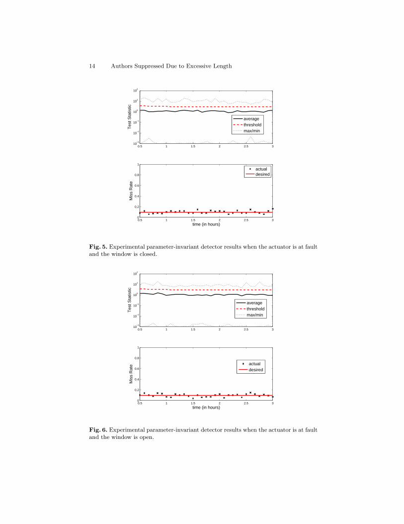
14 Authors Suppressed Due to Excessive Length
0.5 1 1.5 2 2.5 310
−3
10−2
10−1
100
101
102
Tes
t Sta
tistic
averagethresholdmax/min
0.5 1 1.5 2 2.5 30
0.2
0.4
0.6
0.8
1
Mis
s R
ate
time (in hours)
actualdesired
Fig. 5. Experimental parameter-invariant detector results when the actuator is at faultand the window is closed.
0.5 1 1.5 2 2.5 310
−3
10−2
10−1
100
101
102
Tes
t Sta
tistic
averagethresholdmax/min
0.5 1 1.5 2 2.5 30
0.2
0.4
0.6
0.8
1
Mis
s R
ate
time (in hours)
actualdesired
Fig. 6. Experimental parameter-invariant detector results when the actuator is at faultand the window is open.
Title Suppressed Due to Excessive Length 15
parison to the performance of the model-based detector in [1], we observe thatthe parameter-invariant detector has nearly constant performance (in terms ofprobability of miss) with both the state of the window and with time, while themodel-based detector exhibits varying performance with both the state of thewindow and with time. Having near-constant performance (which matches thespecification) is preferred as it allows a building manager to reliable select theprobability of missed detection of actuator fault.
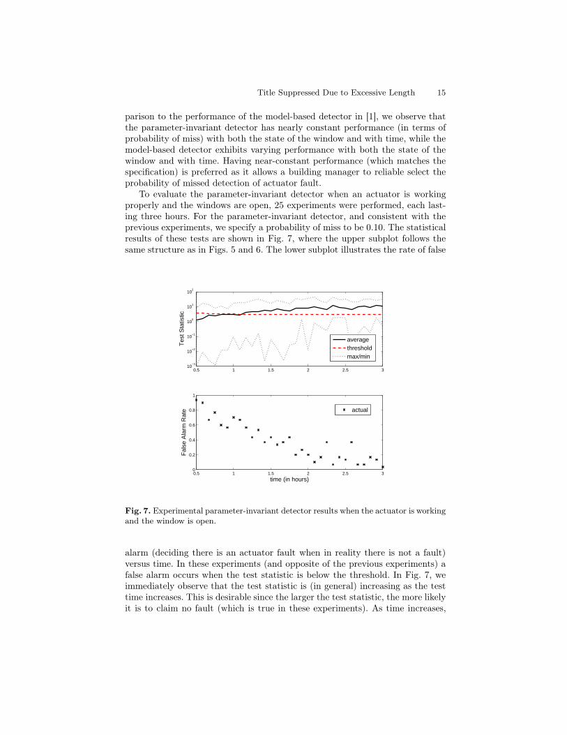
To evaluate the parameter-invariant detector when an actuator is workingproperly and the windows are open, 25 experiments were performed, each last-ing three hours. For the parameter-invariant detector, and consistent with theprevious experiments, we specify a probability of miss to be 0.10. The statisticalresults of these tests are shown in Fig. 7, where the upper subplot follows thesame structure as in Figs. 5 and 6. The lower subplot illustrates the rate of false
0.5 1 1.5 2 2.5 310
−3
10−2
10−1
100
101
102
Tes
t Sta
tistic
averagethresholdmax/min
0.5 1 1.5 2 2.5 30
0.2
0.4
0.6
0.8
1
Fal
se A
larm
Rat
e
time (in hours)
actual
Fig. 7. Experimental parameter-invariant detector results when the actuator is workingand the window is open.
alarm (deciding there is an actuator fault when in reality there is not a fault)versus time. In these experiments (and opposite of the previous experiments) afalse alarm occurs when the test statistic is below the threshold. In Fig. 7, weimmediately observe that the test statistic is (in general) increasing as the testtime increases. This is desirable since the larger the test statistic, the more likelyit is to claim no fault (which is true in these experiments). As time increases,
16 Authors Suppressed Due to Excessive Length
we observe from the lower subplot that the rate of miss is (in general) decreas-ing. The reason for non-monotonic performance is explained by the fact only 25experiments were used to evaluate the parameter-invariant detector when theactuator is working and the windows are open. These results illustrate that per-formance (in terms of false alarm rate) can be improved (decreased) by allowingthe parameter-invariant detector to run for longer time periods. For this roomand configuration, a false alarm rate of 0.05 can be achieved by allowing theparameter-invariant detector to run for 3 hours. Depending on the zone (room)and its interactions with the adjacent zones, the probability of false alarm willvary. However, this variance is generally acceptable in practice so long as theprobability of miss remains constant since it implies that by simply letting thetest run longer will yield improved performance.
6 Discussion and Future Work
The parameter-invariant detector introduced in this work for building HVACsystems is based on a previously designed CFAR detector for networked systems,where the parameter-invariant detector with constant performance is designedto replace the model-based detector with unpredictably varying performance inthe HVAC FDD scheme previously developed. The parameter-invariant detectoris designed to maintain a constant probability of missing a fault, invariant to theunknown and time-varying building parameters. An experimental testbed usinga real HVAC system is described that allows automatic sensing and actuation ofseveral HVAC components. Future work includes a full evaluation of the two-tierfault detection strategy on the KTH HVAC testbed and extending the detectiontheory to handle the detection of faulty sensors and imminent actuator failure(i.e. detecting whether the actuator range of motion has decreased).
References
1. J. Weimer, A. Ahmadi, J. Araujo, F. Mele, D. Papale, I. Shames, H. Sandberg, K.H. Johansson, Active Actuator Fault Detection and Diagnostics in HVAC Systems,In 4th ACM Workshop On Embedded Sensing Systems For Energy-Efficiency InBuildings (BuildSys 2012)
2. J. Weimer, D. Varagnolo, K. Johansson, Distributed Model-Invariant Detection ofUnknown Inputs in Networked Systems In 2nd ACM International Conference onHigh Confidence Networked Systems (HiCoNS) 2013.
3. J. Široký, F. Oldewurtel, J. Cigler, and S. Prívara Experimental analysis of modelpredictive control for an energy efficient building heating system. Applied Energy,88(9):3079 – 3087, 2011.
4. Y. Agarwal, B. Balaji, S. Dutta, R. Gupta, and T. Weng. Duty-cycling buildingsaggressively: The next frontier in HVAC control. In Information Processing inSensor Networks (IPSN), 2011 10th International Conference on, pages 246 –257,April 2011.
5. A. Aswani, N. Master, J. Taneja, D. Culler, and C. Tomlin. Reducing transientand steady state electricity consumption in HVAC using learning-based model-predictive control. Proceedings of the IEEE, 100(1):240 –253, Jan. 2012.

Title Suppressed Due to Excessive Length 17
6. W. Chow. Application of computational fluid dynamics in building services engi-neering. Building and Environment, 31(5):425–436, 1996.
7. T. M. Cover and J. A. Thomas. Elements of Information Theory. Wiley-Interscience, New York, NY, USA, 1991.
8. D. Crawley, L. Lawrie, F. Winkelmann, W. Buhl, Y. Huang, C. Pedersen,R. Strand, R. Liesen, D. Fisher, M. Witte, et al. Energyplus: creating a new-generation building energy simulation program. Energy and Buildings, 33(4):319–331, 2001.
9. K. Deng, P. Barooah, P. Mehta, and S. Meyn. Building thermal model reductionvia aggregation of states. In IEEE Proceedings of the American Control Conference(ACC), pages 5118–5123., July, 2010.
10. N. Djuric and V. Novakovic. Review of possibilities and necessities for buildinglifetime commissioning. Renewable and Sustainable Energy Reviews, 13(2):486 –492, 2009.
11. V. Erickson, M. Carreira-Perpinan, and A. Cerpa. Observe: Occupancy-basedsystem for efficient reduction of HVAC energy. In 10th International Conferenceon Information Processing in Sensor Networks (IPSN), pages 258 –269, Apr. 2011.
12. N. Fernandez, M. Brambley, S. Katipamula, H. Cho, J. Goddard, and L. Dinh.Self correcting HVAC controls project final report PNNL-19074. Technical report,Pacific Northwest National Laboratory, Richland, WA., 2009.
13. M. Gouda, S. Danaher, and C. Underwood. Building thermal model reduction usingnonlinear constrained optimization. Building and Environment, 37(12):1255–1265,2002.
14. L. Jagemar and D. Olsson. The EPBD and continuous commisioning. Technicalreport, CIT Energy Mangement AB, Goteborg, Sweden, Oct. 2007.
15. S. Katipamula and M. R. Brambley. Methods for fault detection, diagnostics, andprognostics for building systems - a review, part ii. HVAC&R Research, 11(2):169-187, Apr. 2005.
16. S. Katipamula and M. R. Brambley. Methods for fault detection, diagnostics, andprognostics for building systems - a review, part i. HVAC&R Research, 11(1):3-25,Jan. 2005.
17. Y. Kim, T. Schmid, M. B. Srivastava, and Y. Wang. Challenges in resource moni-toring for residential spaces. In Proceedings of the First ACM Workshop on Embed-ded Sensing Systems for Energy-Efficiency in Buildings, BuildSys ’09, pages 1–6,New York, NY, USA, 2009.
18. J. Lu, T. Sookoor, V. Srinivasan, G. Gao, B. Holben, J. Stankovic, E. Field, andK. Whitehouse. The smart thermostat: using occupancy sensors to save energy inhomes. In Proceedings of the 8th ACM Conference on Embedded Networked SensorSystems, SenSys ’10, pages 211–224, New York, NY, USA, 2010.
19. J. Ma, J. Qin, T. Salsbury, and P. Xu. Demand reduction in building energy sys-tems based on economic model predictive control. Chemical Engineering Science,67(1):92 – 100, 2012.
20. Y. Ma, A. Kelman, A. Daly, and F. Borrelli. Predictive control for energy efficientbuildings with thermal storage: Modeling, stimulation, and experiments. ControlSystems, IEEE, 32(1):44 –64, Feb. 2012.
21. A. Marchiori and Q. Han. Distributed wireless control for building energy man-agement In Proceedings of the 2nd ACM Workshop on Embedded Sensing Systemsfor Energy-Efficiency in Building, BuildSys ’10, pages 37–42, New York, NY, USA,2010.

18 Authors Suppressed Due to Excessive Length
22. A. Melman. Geometry and convergence of euler’s and halley’s methods. In SIAMReview, volume 39, pages 728–735. Society for Industrial and Applied Mathematics,Dec. 1997.
23. T. X. Nghiem, M. Behl, R. Mangharam, and G. J. Pappas. Scalable schedul-ing of building control systems for peak demand reduction. In American ControlConference, Jun. 2012.
24. F. Oldewurtel, A. Parisio, C. N. Jones, D. Gyalistras, M. Gwerder, V. Stauch,B. Lehmann, and M. Morari. Use of model predictive control and weather forecastsfor energy efficient building climate control. Energy and Buildings, 45(0):15–27,2012.
25. H. A. I. S. Goyal and P. Barooah. Zone level control algorithms based on occupancyinformation for energy efficient buildings. In American Control Conference, Jun.2012.
26. J. Seem, S. Klein, W. Beckman, and J. Mitchell. Transfer functions for efficientcalculation of multidimensional transient heat transfer. Journal of heat transfer,111:5, 1989.
27. UK Department of Trade and Industry. DTI, Energy Trends 2005. Departmentof Trade and Industry, London, 2011.
28. U.S. Department of Energy. Energy Efficiency Trends in Residential and Com-mercial Buildings. U.S. Department of Energy, Oct. 2008.
29. A. Wald. Sequential Analysis. John Wiley & Sons, Inc., New York, 1947.