parametric modeling of aircraft fuel systems … · parametric modeling of aircraft fuel systems...
TRANSCRIPT
PARAMETRIC MODELING OF AIRCRAFT FUEL SYSTEMSINTEGRATION IN RAPID
Adrián Sabaté López and Raghu Chaitanya MunjuluryLinköping University, Linköping, Sweden
Keywords: Aircraft design, RAPID, Fuel systems, Knowledge-based engineering, CATIA
Abstract
This work presents knowledge-based parametricdefinition of aircraft fuel systems, oriented to itsuse in conceptual design and integrated into theRAPID design tool. Fuel systems appear earlyin the design process as they are involved in sev-eral first estimations. For instance, fuel weight isa significant part of take-off weight and decisivein aircraft sizing and range estimations. There-fore, including fuel systems earlier in the designprocess creates an opportunity to optimize it andobtain better solutions.
1 Introduction
The use of CAD methods is extended to most ofthe aircraft design process, yet the conceptual de-sign phase has singular requirements that don’tmatch the usual concept of these tools. Concep-tual design is often an iterative process wherethe designer’s ideas need to be defined in a fastway and therefore the level of detail of the de-sign is often kept to the minimum. However, itis also highly multi-disciplinary as the designeror designing team has to take into account sev-eral disciplines such as aerodynamics, structureor system integration. As detail and exactitudeof 3D modeling do not look like a great advan-tage that could compensate the time employedin it, conceptual design also covers weight esti-mation, aerodynamic calculations, payload andrange requirements that will be repeated severaltimes and it is advantages to have the CAD modelfor better prediction.
RAPID (Robust Aircraft Parametric Interac-
tive Design) is a knowledge-based aircraft ge-ometry design tool that is being developed atthe Division of Fluid and Mechatronic Systemsof Linköping University [1]. This project is acontinuation in line of work with integration offunctional systems in RAPID [2] as aircraft sys-tems integration is needed to estimate the volumeavailable for best fit of the components [1].
Parametric design seeks for fast as well as aflexible definition of the CAD model while theknowledge template concept is useful in a multi-disciplinary environment as each specialist cantransfer his experience and knowledge in the toolfor the rest of the design team to use it.
Fuel capacity is directly related to range per-formance, one of the basic requirements whendesigning a new aircraft [3]. In the same way,position of the fuel tanks has a big influencein balance and therefore maneuverability, influ-encing in take-off and landing distances. Eventhough, fuel system considerations are tradition-ally placed in the preliminary design phase [4]yet new tools can change this tendency.
2 Objectives
The goal is to take advantage of CAD in the earlystages of aircraft design by allowing the designerto define the fuel system with parameters andconsequently be able to measure fuel capacity orsee fuel tank’s position and a first outline of thefuel system in a 3D model.
The project followed the steps stated below inorder to achieve the main goal:
1. Plan how to represent the main functions offuel systems in civil aircraft:
1
SABATÉ LÓPEZ, MUNJULURY
• Engine feed.
• Fuel transfer.
• Refuel/defuel.
• Tank venting.
2. Create templates that represent the geome-tries of the main components of the fuelsystem in a flexible way.
3. Use Knowledge Pattern to instantiate thesecomponents in a preexisting aircraft geom-etry defined in RAPID.
4. Use parameters to modify the general lay-out of the components in the system.
5. Connect the defined components in the fuelsystem regarding the preexisting aircraftgeometry.
6. Use parameters to take measures of vari-ables that can be useful in conceptual orpreliminary design.
3 Simplifications
The target application of this fuel system modelis conceptual to preliminary design. In addition,aircraft designers need enough flexibility to de-fine new ideas and cover several types of aircraftand configurations. Therefore some simplifica-tions were made in order to create this model inan optimum way:
• All geometries are symbolic, representinga space allocation inside the aircraft for thefuel system. They are not a realistic rep-resentation of real components as that taskcan be realized in detail design.
• Smaller geometries as valves or fuel in-takes inside the tanks are not represented.
• Fuel quantity measuring system is not in-cluded as it is a challenging design taskcomplex to automatize and occupies asmall space compared with other systemfunctions.
• Symmetry is applied in the whole system,but both sides are represented.
• Fuel tubing or piping is often representedwith direct lines between two pumps ortanks and represent the minimum lengthneeded of this component. An exceptionfor this is the pipe connecting fuel tanksfrom the tail to the fuselage, which wasrepresented with more detail.
• Wing and horizontal stabilizer spars arerepresented as surfaces limiting the tanks,as a structural model integrated in RAPIDwas still being developed during the real-ization of this work.
• Only representative fuel system layouts arerepresented in this model, as there can bea big number of layout alternatives used inthe industry.
4 Development of Fuel Systems
This section describes the fuel system inte-gration in the RAPID tool from a tool de-signer/programmer point of view, going from awider to a more detailed view of its characteris-tics and ending by describing all of its compo-nents and function. Anyway, specific code andtool application examples are not included in thisdocument. Design automation is performed us-ing Knowledge pattern feature in CATIA R© [5]. Ituses a UDF (User Defined Feature), a catalog andscript for instantiation.
4.1 Parametric control
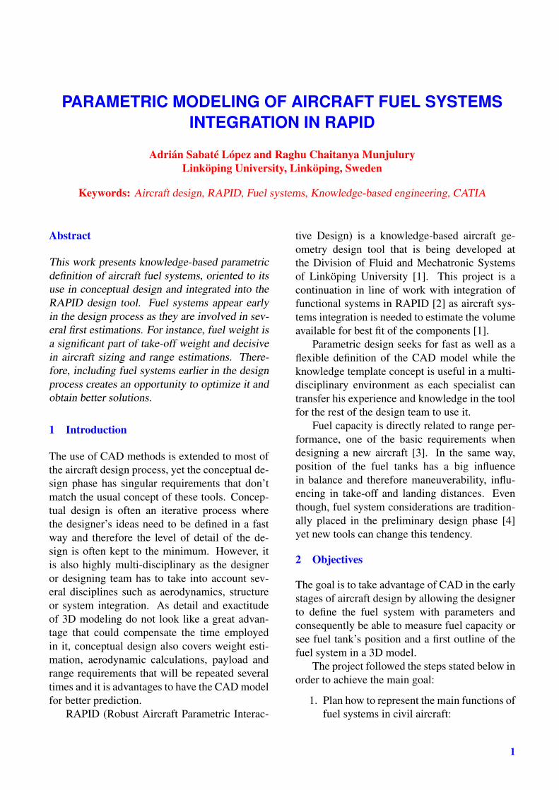
At Part level, the logic that the design tool willuse when instantiating the UDFs is controlled bya set of 13 parametersFurthermore, three outputparameters will give the user fuel capacity andtubing length measures and other four parametersmake global changes in the instantiated UDFs tomake weight balance related measurement. Anexample of parameter values is shown in Figure1. At a UDF level, each component characteris-tics, position, shape and measurements are visi-ble as published parameters (see Figure 3). The
2
Parametric Modeling of Aircraft Fuel Systems integration in RAPID
number of parameters in each UDF is comprisedbetween 4 and 25, but in the case of common val-ues such as Fuel Density in the tanks or valuesdetermined by the system layout as for examplesymmetry of a specific pipe.
Fig. 1 Part level parameters controlling the fuelsystem.
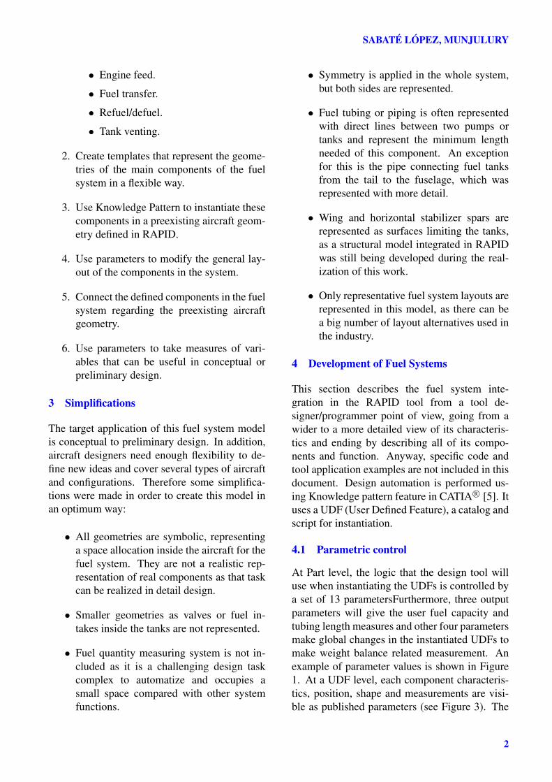
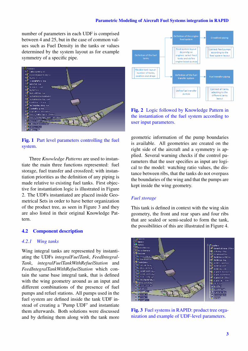
Three Knowledge Patterns are used to instan-tiate the main three functions represented: fuelstorage, fuel transfer and crossfeed; with instan-tiation priorities as the definition of any piping ismade relative to existing fuel tanks. First objec-tive for instantiation logic is illustrated in Figure2. The UDFs instantiated are placed inside Geo-metrical Sets in order to have better organizationof the product tree, as seen in Figure 3 and theyare also listed in their original Knowledge Pat-tern.
4.2 Component description
4.2.1 Wing tanks
Wing integral tanks are represented by instanti-ating the UDFs integralFuelTank, FeedIntegral-Tank, integralFuelTankWithRefuelStation andFeedIntegralTankWithRefuelStation which con-tain the same base integral tank, that is definedwith the wing geometry around as an input anddifferent combinations of the presence of fuelpumps and refuel stations. All pumps used in thefuel system are defined inside the tank UDF in-stead of creating a ’Pump UDF’ and instantiatethem afterwards. Both solutions were discussedand by defining them along with the tank more
Fig. 2 Logic followed by Knowledge Pattern inthe instantiation of the fuel system according touser input parameters.
geometric information of the pump boundariesis available. All geometries are created on theright side of the aircraft and a symmetry is ap-plied. Several warning checks if the control pa-rameters that the user specifies as input are logi-cal to the model: watching ratio values, the dis-tance between ribs, that the tanks do not overpassthe boundaries of the wing and that the pumps arekept inside the wing geometry.
Fuel storage
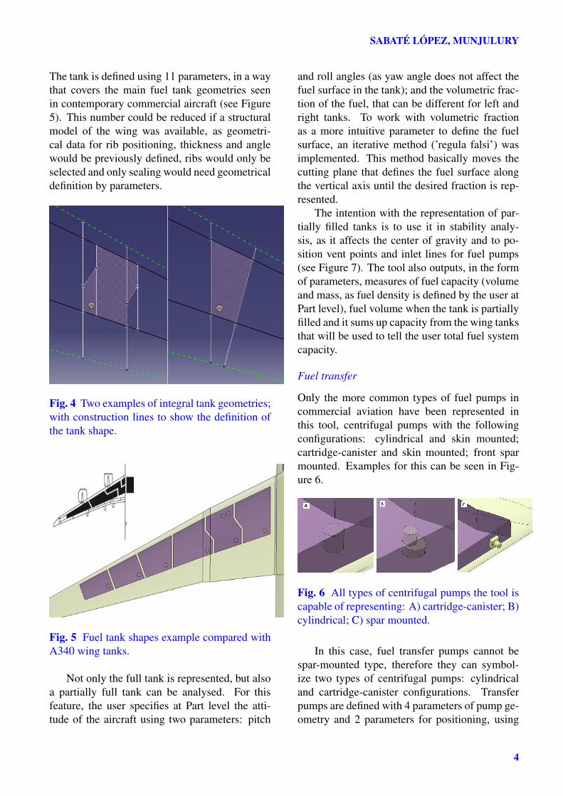
This tank is defined in context with the wing skingeometry, the front and rear spars and four ribsthat are sealed or semi-sealed to form the tank,the possibilities of this are illustrated in Figure 4.
Fig. 3 Fuel systems in RAPID: product tree orga-nization and example of UDF-level parameters.
3
SABATÉ LÓPEZ, MUNJULURY
The tank is defined using 11 parameters, in a waythat covers the main fuel tank geometries seenin contemporary commercial aircraft (see Figure5). This number could be reduced if a structuralmodel of the wing was available, as geometri-cal data for rib positioning, thickness and anglewould be previously defined, ribs would only beselected and only sealing would need geometricaldefinition by parameters.
Fig. 4 Two examples of integral tank geometries;with construction lines to show the definition ofthe tank shape.
Fig. 5 Fuel tank shapes example compared withA340 wing tanks.
Not only the full tank is represented, but alsoa partially full tank can be analysed. For thisfeature, the user specifies at Part level the atti-tude of the aircraft using two parameters: pitch
and roll angles (as yaw angle does not affect thefuel surface in the tank); and the volumetric frac-tion of the fuel, that can be different for left andright tanks. To work with volumetric fractionas a more intuitive parameter to define the fuelsurface, an iterative method (’regula falsi’) wasimplemented. This method basically moves thecutting plane that defines the fuel surface alongthe vertical axis until the desired fraction is rep-resented.
The intention with the representation of par-tially filled tanks is to use it in stability analy-sis, as it affects the center of gravity and to po-sition vent points and inlet lines for fuel pumps(see Figure 7). The tool also outputs, in the formof parameters, measures of fuel capacity (volumeand mass, as fuel density is defined by the user atPart level), fuel volume when the tank is partiallyfilled and it sums up capacity from the wing tanksthat will be used to tell the user total fuel systemcapacity.
Fuel transfer
Only the more common types of fuel pumps incommercial aviation have been represented inthis tool, centrifugal pumps with the followingconfigurations: cylindrical and skin mounted;cartridge-canister and skin mounted; front sparmounted. Examples for this can be seen in Fig-ure 6.
Fig. 6 All types of centrifugal pumps the tool iscapable of representing: A) cartridge-canister; B)cylindrical; C) spar mounted.
In this case, fuel transfer pumps cannot bespar-mounted type, therefore they can symbol-ize two types of centrifugal pumps: cylindricaland cartridge-canister configurations. Transferpumps are defined with 4 parameters of pump ge-ometry and 2 parameters for positioning, using
4
Parametric Modeling of Aircraft Fuel Systems integration in RAPID
rear spar as a reference in order to separate themfrom the feed pumps that will be placed near thefront spar, most likely the position closest to theengines. They are always placed in the bottom ofthe tank.
Engine feed
Feed pumps can be of all types. They are de-fined with one parameter for pump type selec-tion and another parameter to make redundancyin feed pumps, a common request for ETOPSregulations; 6 parameters size and position thepump and another one positions the second pumpwhen redundancy is selected.
Refuel system
One refuel station for the aircraft can be addedwith one parameter at Part level. It is situated inthe right wing as commercial aircraft are usuallyloaded from the left side and consists in a simplerectangular representation placed in the bottomof an integral tank.
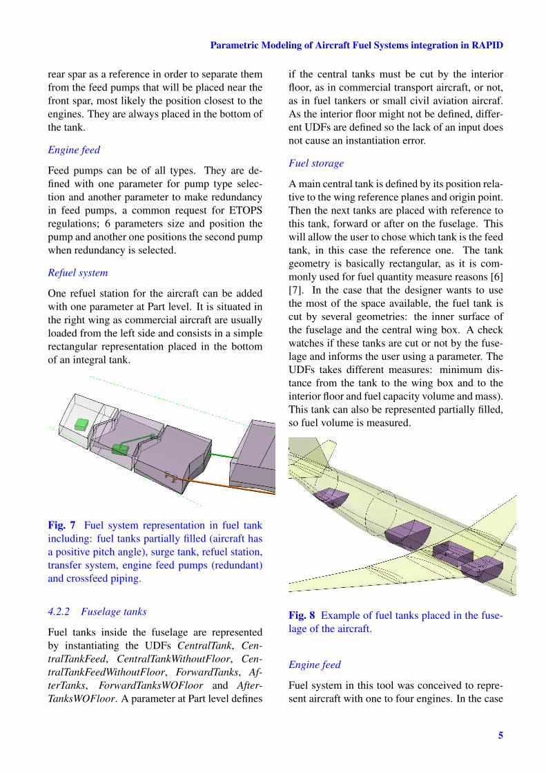
Fig. 7 Fuel system representation in fuel tankincluding: fuel tanks partially filled (aircraft hasa positive pitch angle), surge tank, refuel station,transfer system, engine feed pumps (redundant)and crossfeed piping.
4.2.2 Fuselage tanks
Fuel tanks inside the fuselage are representedby instantiating the UDFs CentralTank, Cen-tralTankFeed, CentralTankWithoutFloor, Cen-tralTankFeedWithoutFloor, ForwardTanks, Af-terTanks, ForwardTanksWOFloor and After-TanksWOFloor. A parameter at Part level defines
if the central tanks must be cut by the interiorfloor, as in commercial transport aircraft, or not,as in fuel tankers or small civil aviation aircraf.As the interior floor might not be defined, differ-ent UDFs are defined so the lack of an input doesnot cause an instantiation error.
Fuel storage
A main central tank is defined by its position rela-tive to the wing reference planes and origin point.Then the next tanks are placed with reference tothis tank, forward or after on the fuselage. Thiswill allow the user to chose which tank is the feedtank, in this case the reference one. The tankgeometry is basically rectangular, as it is com-monly used for fuel quantity measure reasons [6][7]. In the case that the designer wants to usethe most of the space available, the fuel tank iscut by several geometries: the inner surface ofthe fuselage and the central wing box. A checkwatches if these tanks are cut or not by the fuse-lage and informs the user using a parameter. TheUDFs takes different measures: minimum dis-tance from the tank to the wing box and to theinterior floor and fuel capacity volume and mass).This tank can also be represented partially filled,so fuel volume is measured.
Fig. 8 Example of fuel tanks placed in the fuse-lage of the aircraft.
Engine feed
Fuel system in this tool was conceived to repre-sent aircraft with one to four engines. In the case
5
SABATÉ LÓPEZ, MUNJULURY
that the aircraft has an odd number of engines,the central tank will act as feed tank for the cen-tral engine. Feed pumps are specified in the cen-tral tank and crossfeed connections connect to it.In fuselage tanks, fuel pumps cannot be fuselagemounted but the other two types. A Rule depend-ing on a parameter is used to activate redundancyof the feed pumps when it is specified by the user.When redundancy is activated, one pump is sym-metrical from the other with reference to the air-craft symmetry plane.
Fuel transfer
Fuselage tanks are the most influential on the po-sition of the aircraft’s center of gravity. The de-signer can use the fuel mass measured by the toolin a parameter, and use CATIA integrated fea-tures to measure the fuel’s center of mass. Thiscan be used mainly in both stability and controlanalysis, and when designing the fuel manage-ment control unit behaviour. Transfer pumps areplaced in the symmetry plane of the aircraft butcan be moved and shaped using 5 parameters.
Fig. 9 Parameters defining a feed central tank.Both feed and transfer pumps are represented
4.2.3 Tail tanks
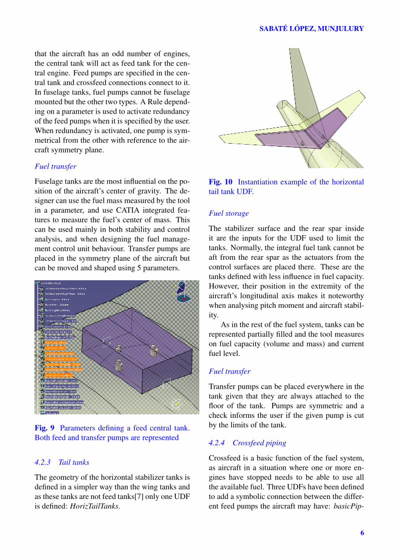
The geometry of the horizontal stabilizer tanks isdefined in a simpler way than the wing tanks andas these tanks are not feed tanks[7] only one UDFis defined: HorizTailTanks.
Fig. 10 Instantiation example of the horizontaltail tank UDF.
Fuel storage
The stabilizer surface and the rear spar insideit are the inputs for the UDF used to limit thetanks. Normally, the integral fuel tank cannot beaft from the rear spar as the actuators from thecontrol surfaces are placed there. These are thetanks defined with less influence in fuel capacity.However, their position in the extremity of theaircraft’s longitudinal axis makes it noteworthywhen analysing pitch moment and aircraft stabil-ity.
As in the rest of the fuel system, tanks can berepresented partially filled and the tool measureson fuel capacity (volume and mass) and currentfuel level.
Fuel transfer
Transfer pumps can be placed everywhere in thetank given that they are always attached to thefloor of the tank. Pumps are symmetric and acheck informs the user if the given pump is cutby the limits of the tank.
4.2.4 Crossfeed piping
Crossfeed is a basic function of the fuel system,as aircraft in a situation where one or more en-gines have stopped needs to be able to use allthe available fuel. Three UDFs have been definedto add a symbolic connection between the differ-ent feed pumps the aircraft may have: basicPip-
6
Parametric Modeling of Aircraft Fuel Systems integration in RAPID
ing, 3pointPiping and basicPipingSparMounted,the last mentioned having a correction in ori-entation when connecting spar-mounted pumps.They consist in a direct tube that will connect twofeed pumps, representing the minimum distanceof tubing that specific configuration needs. In or-der to make a more realistic representation, bettersolutions lay in specific CATIA workbenches asSystem routing, Piping design and Tubing designif automation can then be implemented.
Fig. 11 Crossfeed piping shown in orange; con-necting four feed tanks with pump redundancy.Transfer piping is shown in green, including theaircraft’s refuel station.
Fig. 12 Detail of 3-engines configuration, where3pointPiping UDF is used.
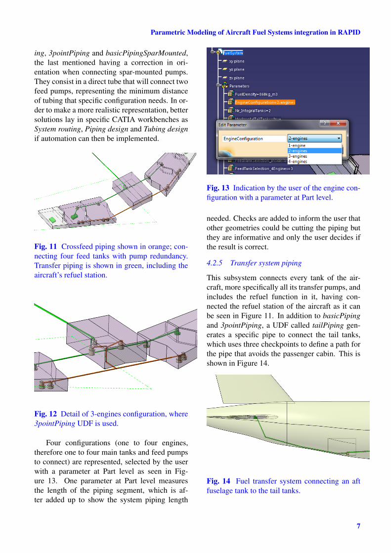
Four configurations (one to four engines,therefore one to four main tanks and feed pumpsto connect) are represented, selected by the userwith a parameter at Part level as seen in Fig-ure 13. One parameter at Part level measuresthe length of the piping segment, which is af-ter added up to show the system piping length
Fig. 13 Indication by the user of the engine con-figuration with a parameter at Part level.
needed. Checks are added to inform the user thatother geometries could be cutting the piping butthey are informative and only the user decides ifthe result is correct.
4.2.5 Transfer system piping
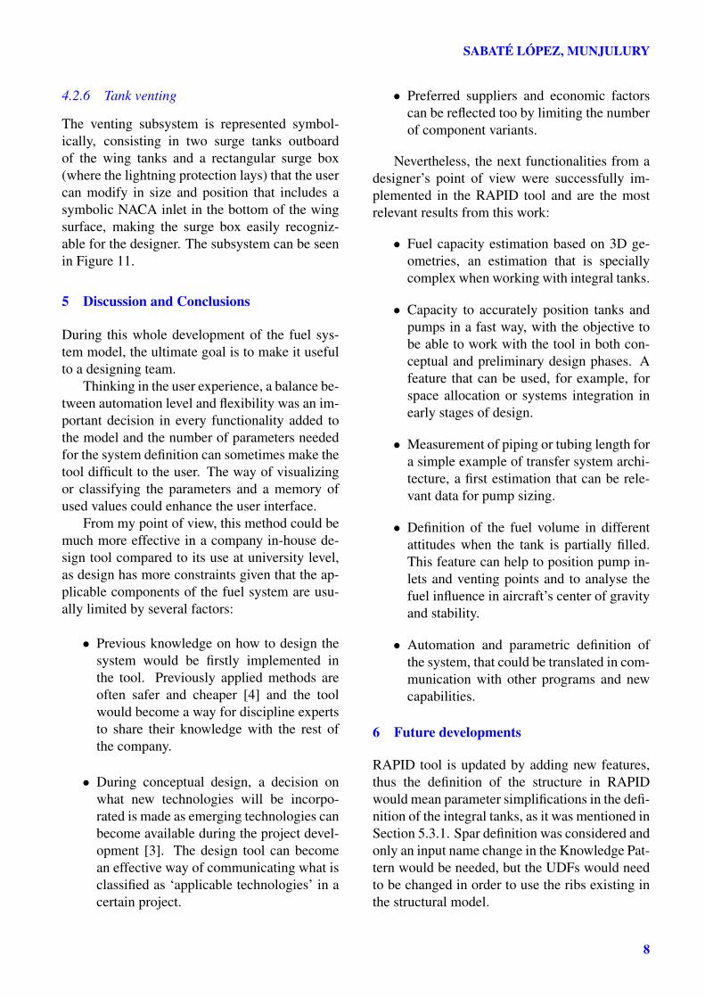
This subsystem connects every tank of the air-craft, more specifically all its transfer pumps, andincludes the refuel function in it, having con-nected the refuel station of the aircraft as it canbe seen in Figure 11. In addition to basicPipingand 3pointPiping, a UDF called tailPiping gen-erates a specific pipe to connect the tail tanks,which uses three checkpoints to define a path forthe pipe that avoids the passenger cabin. This isshown in Figure 14.
Fig. 14 Fuel transfer system connecting an aftfuselage tank to the tail tanks.
7
SABATÉ LÓPEZ, MUNJULURY
4.2.6 Tank venting
The venting subsystem is represented symbol-ically, consisting in two surge tanks outboardof the wing tanks and a rectangular surge box(where the lightning protection lays) that the usercan modify in size and position that includes asymbolic NACA inlet in the bottom of the wingsurface, making the surge box easily recogniz-able for the designer. The subsystem can be seenin Figure 11.
5 Discussion and Conclusions
During this whole development of the fuel sys-tem model, the ultimate goal is to make it usefulto a designing team.
Thinking in the user experience, a balance be-tween automation level and flexibility was an im-portant decision in every functionality added tothe model and the number of parameters neededfor the system definition can sometimes make thetool difficult to the user. The way of visualizingor classifying the parameters and a memory ofused values could enhance the user interface.
From my point of view, this method could bemuch more effective in a company in-house de-sign tool compared to its use at university level,as design has more constraints given that the ap-plicable components of the fuel system are usu-ally limited by several factors:
• Previous knowledge on how to design thesystem would be firstly implemented inthe tool. Previously applied methods areoften safer and cheaper [4] and the toolwould become a way for discipline expertsto share their knowledge with the rest ofthe company.
• During conceptual design, a decision onwhat new technologies will be incorpo-rated is made as emerging technologies canbecome available during the project devel-opment [3]. The design tool can becomean effective way of communicating what isclassified as ‘applicable technologies’ in acertain project.
• Preferred suppliers and economic factorscan be reflected too by limiting the numberof component variants.
Nevertheless, the next functionalities from adesigner’s point of view were successfully im-plemented in the RAPID tool and are the mostrelevant results from this work:
• Fuel capacity estimation based on 3D ge-ometries, an estimation that is speciallycomplex when working with integral tanks.
• Capacity to accurately position tanks andpumps in a fast way, with the objective tobe able to work with the tool in both con-ceptual and preliminary design phases. Afeature that can be used, for example, forspace allocation or systems integration inearly stages of design.
• Measurement of piping or tubing length fora simple example of transfer system archi-tecture, a first estimation that can be rele-vant data for pump sizing.
• Definition of the fuel volume in differentattitudes when the tank is partially filled.This feature can help to position pump in-lets and venting points and to analyse thefuel influence in aircraft’s center of gravityand stability.
• Automation and parametric definition ofthe system, that could be translated in com-munication with other programs and newcapabilities.
6 Future developments
RAPID tool is updated by adding new features,thus the definition of the structure in RAPIDwould mean parameter simplifications in the defi-nition of the integral tanks, as it was mentioned inSection 5.3.1. Spar definition was considered andonly an input name change in the Knowledge Pat-tern would be needed, but the UDFs would needto be changed in order to use the ribs existing inthe structural model.
8
Parametric Modeling of Aircraft Fuel Systems integration in RAPID
The objective of connecting the tool with Mi-crosoft Excel was not fulfilled for time restric-tions, but it seems a simple exercise of VisualBasic scripting as it was implemented in [2]. Abetter visualization of the parameters for the userand a memory of previously used values is a morecomplex task that could enhance the user’s expe-rience. The model has an order of definition ofthe parameters: from the part parameters to theUDF parameters and following the relations be-tween different UDFs. This means that currentlyin the tool, changes in reverse order will make theuser defining again the parameters of the UDFsthat need to be instantiated.
To conclude, a lot of possibilities are openedwhen having an automated, parametric definitionof part of the fuel system and taking measuresfrom it. In my opinion, connecting this auto-mated definition of the fuel systems with an op-timization program could lead to the most inter-esting results of this work, as currently the toolmeasures characteristics of the system that canbe part of the optimization objective, using themodel as objective function while the parametersare changed.
References
[1] Munjulury, R. C., Knowledge Based IntegratedMultidisciplinary Aircraft Conceptual Design,Licentiate thesis no. 1661, Department of Man-agement and Engineering, Linköping University,Linköping, Sweden, 2014.
[2] Andrés, I. E. and Munjulury, R. C., “Knowledge-Based Flight Control System Integration inRAPID,” Tech. rep., Institute of Technology,Linköping University, 2015.
[3] Raymer, D. P., Aircraft Design: A ConceptualApproach, AIAA Education Series, American In-stitute of Aeronautics and Astronautics, 2nd ed.,2006.
[4] Torenbeek, E., Synthesis of Subsonic AirplaneDesign, Delft University Press, 1982.
[5] “CATIA V5 Release21,” "[Online; Accessed 8-Aug-2015]", http://www.3ds.com/.
[6] Langton, R., Clark, C., Hewitt, M., and Richards,L., Aircraft Fuel Systems, Aerospace Series, JohnWiley and Sons, 2009.
[7] Moir, I. and Seabridge, A., Aircraft Systems:Mechanical, Electrical and Avionics SubsystemsIntegration, Aerospace Series, John Wiley andSons, 2008.
9