parametric multiphysics simulation -...
TRANSCRIPT

CADFEM GmbH November 2013
Parametric Multiphysics Simulation
Christof Gebhardt
CADFEM GmbH, Grafing bei München, Germany
Summary: Multiphysics simulations improve the understanding of complex physical processes in multiple physical domains. As an example, the ampacitiy calculation for electrical power connector is shown with its nonlinear electric-thermal-mechanical behavior. The typical workflow from sensitivity, optimization to robustness assessment gives insights in results to achieve and improvements to realize. Keywords: Multiphysics, multidomain, domain, nonlinear, coupled, coupling, connector, ampacity, temperature dependent, pressure dependent, resistance, conductivity, plasticity, optimization, sensitivity, robustness, RDO, DoE, ACT, FEM, FEA, CAE

CADFEM GmbH November 2013
1 Introduction
The simulation of complex physical phenomena requires more and more an interaction between physical domains such as structural mechanics, temperature, fluid flow and electromagnetism. The influence among each other plays an important role to achieve reliable simulation results and to make the right decisions in a virtual product development. Nowadays, simulation software allows us to couple these domains to get a deeper understanding for our products in a so called multiphysics simulation.
Picture 1: A multiphysics Analysis in ANSYS Workbench including electromagnetics, thermal and structural simulation To make such a multiphysics simulation a driving factor for a simulation driven product development, a second component is necessary: A fully parametric workflow which covers the complete simulation process – from CAD import, geometry preparation, material modeling, meshing, boundary definition to solution and result processing for all the included physical domains and all levels of detail. This parametric workflow enables sensitivity studies for a better understanding of the relation between design parameters and results, the relation between results and the importance of certain design parameters. In addition, optimization can be used to achieve a best design for multiple, competitive goals. To consider the safety of a product in real product lifecycle conditions, the scatter in all the relevant input parameters like material, geometry tolerances and varying load conditions can be included and allow the prediction of failure probabilities.
2 Multiphysics Simulation of a Connector
A typical representative for multiphysics simulation applications are electrical connectors. The requirements of connectors used in industries are immense. For designers, it is important that the connector fulfills all conditions in everyday use. High reliability, signal integrity, optimal electrical, thermal und mechanical properties of a connector is in the focus of a designer. Faulty goods should not arise – the opposite is the request without losing the sight of the price. As an example for a high current connector, picture 2 shows a connector, consisting of a spring cage which is inserted in an outer jacket. A pin is inserted so that a current flow is transmitted by the contact between the pin and cage as well as between the cage and jacket.
Picture 2: Connector with jacket, spring cage and inserted pin
pin
cage
jacket
CADFEM GmbH November 2013
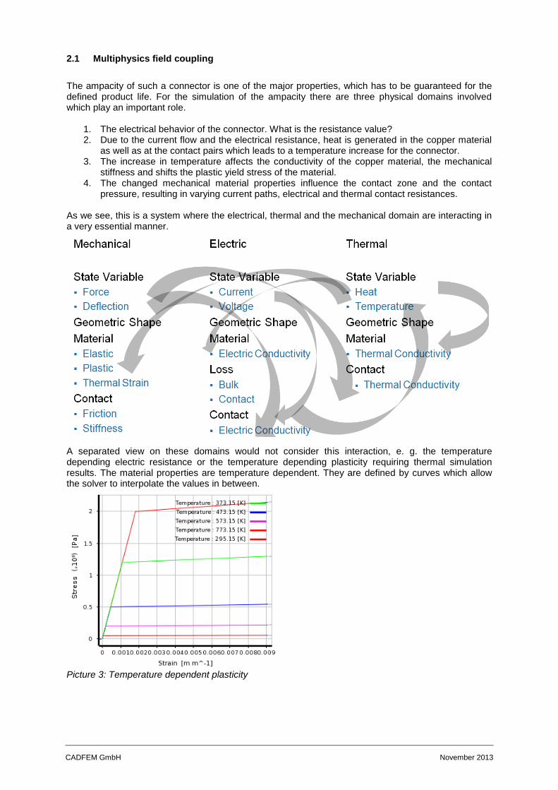
2.1 Multiphysics field coupling
The ampacity of such a connector is one of the major properties, which has to be guaranteed for the defined product life. For the simulation of the ampacity there are three physical domains involved which play an important role.
1. The electrical behavior of the connector. What is the resistance value? 2. Due to the current flow and the electrical resistance, heat is generated in the copper material
as well as at the contact pairs which leads to a temperature increase for the connector. 3. The increase in temperature affects the conductivity of the copper material, the mechanical
stiffness and shifts the plastic yield stress of the material. 4. The changed mechanical material properties influence the contact zone and the contact
pressure, resulting in varying current paths, electrical and thermal contact resistances. As we see, this is a system where the electrical, thermal and the mechanical domain are interacting in a very essential manner.
A separated view on these domains would not consider this interaction, e. g. the temperature depending electric resistance or the temperature depending plasticity requiring thermal simulation results. The material properties are temperature dependent. They are defined by curves which allow the solver to interpolate the values in between.
Picture 3: Temperature dependent plasticity
CADFEM GmbH November 2013
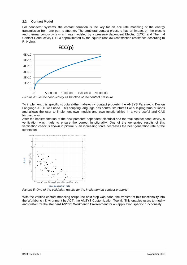
2.2 Contact Model
For connector systems, the contact situation is the key for an accurate modeling of the energy transmission from one part to another. The structural contact pressure has an impact on the electric and thermal conductivity which was modeled by a pressure dependent Electric (ECC) and Thermal Contact Conductivity (TCC) approximated by the square root law (constriction resistance according to R. Holm).
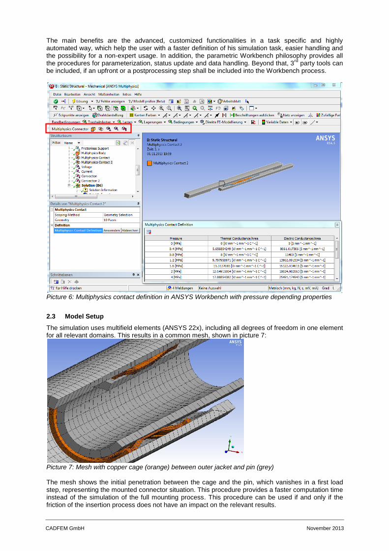
Picture 4: Electric conductivity as function of the contact pressure To implement this specific structural-thermal-electric contact property, the ANSYS Parametric Design Language APDL was used. This scripting language has control structures like sub-programs or loops and allows the user to implement own models and own functionalities in a very useful and CAE focused way. After the implementation of the new pressure dependent electrical and thermal contact conductivity, a verification was made to ensure the correct functionality. One of the generated results of this verification check is shown in picture 5: an increasing force decreases the heat generation rate of the connector:
Picture 5: One of the validation results for the implemented contact property With the verified contact modeling script, the next step was done: the transfer of this functionality into the Workbench Environment by ACT, the ANSYS Customization Toolkit. This enables users to modify and customize the standard ANSYS Workbench Environment for an application specific functionality.
CADFEM GmbH November 2013
The main benefits are the advanced, customized functionalities in a task specific and highly automated way, which help the user with a faster definition of his simulation task, easier handling and the possibility for a non-expert usage. In addition, the parametric Workbench philosophy provides all the procedures for parameterization, status update and data handling. Beyond that, 3
rd party tools can
be included, if an upfront or a postprocessing step shall be included into the Workbench process.
Picture 6: Multiphysics contact definition in ANSYS Workbench with pressure depending properties
2.3 Model Setup
The simulation uses multifield elements (ANSYS 22x), including all degrees of freedom in one element for all relevant domains. This results in a common mesh, shown in picture 7:
Picture 7: Mesh with copper cage (orange) between outer jacket and pin (grey) The mesh shows the initial penetration between the cage and the pin, which vanishes in a first load step, representing the mounted connector situation. This procedure provides a faster computation time instead of the simulation of the full mounting process. This procedure can be used if and only if the friction of the insertion process does not have an impact on the relevant results.

CADFEM GmbH November 2013
In a second step, the current flow is activated. For the electric domain, the electric ground is defined at one end and the current at the opposite side. Assuming that radiation and convection of the connector itself does not play a major role for the cooling, the thermal conduction into the cables is modeled by a convection boundary condition with a high heat transfer rate.
Picture 8: Complete set of multiphysics boundary conditions within ANSYS Workbench
2.4 Computation and Results
The ANSYS Solver computes the equilibrium of the mechanical deformation with elastic and plastic strain, the voltage drop in the connector with the local current paths and the joule heating as well as the resulting temperature distribution.
Picture 9: Iterative solution process of nonlinear multiphysics connector model
CADFEM GmbH November 2013
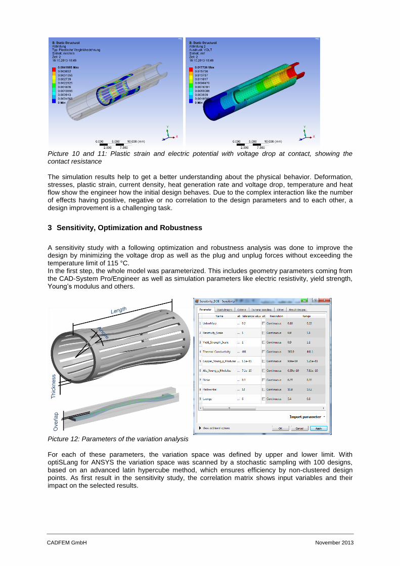
Picture 10 and 11: Plastic strain and electric potential with voltage drop at contact, showing the contact resistance The simulation results help to get a better understanding about the physical behavior. Deformation, stresses, plastic strain, current density, heat generation rate and voltage drop, temperature and heat flow show the engineer how the initial design behaves. Due to the complex interaction like the number of effects having positive, negative or no correlation to the design parameters and to each other, a design improvement is a challenging task.
3 Sensitivity, Optimization and Robustness
A sensitivity study with a following optimization and robustness analysis was done to improve the design by minimizing the voltage drop as well as the plug and unplug forces without exceeding the temperature limit of 115 °C. In the first step, the whole model was parameterized. This includes geometry parameters coming from the CAD-System Pro/Engineer as well as simulation parameters like electric resistivity, yield strength, Young’s modulus and others.
Picture 12: Parameters of the variation analysis For each of these parameters, the variation space was defined by upper and lower limit. With optiSLang for ANSYS the variation space was scanned by a stochastic sampling with 100 designs, based on an advanced latin hypercube method, which ensures efficiency by non-clustered design points. As first result in the sensitivity study, the correlation matrix shows input variables and their impact on the selected results.
CADFEM GmbH November 2013
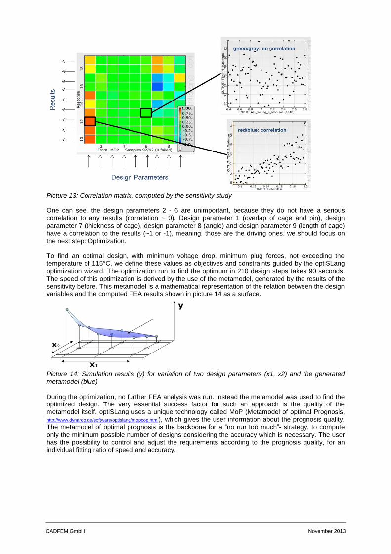
Picture 13: Correlation matrix, computed by the sensitivity study One can see, the design parameters 2 - 6 are unimportant, because they do not have a serious correlation to any results (correlation ~ 0). Design parameter 1 (overlap of cage and pin), design parameter 7 (thickness of cage), design parameter 8 (angle) and design parameter 9 (length of cage) have a correlation to the results (~1 or -1), meaning, those are the driving ones, we should focus on the next step: Optimization. To find an optimal design, with minimum voltage drop, minimum plug forces, not exceeding the temperature of 115°C, we define these values as objectives and constraints guided by the optiSLang optimization wizard. The optimization run to find the optimum in 210 design steps takes 90 seconds. The speed of this optimization is derived by the use of the metamodel, generated by the results of the sensitivity before. This metamodel is a mathematical representation of the relation between the design variables and the computed FEA results shown in picture 14 as a surface.
Picture 14: Simulation results (y) for variation of two design parameters (x1, x2) and the generated metamodel (blue) During the optimization, no further FEA analysis was run. Instead the metamodel was used to find the optimized design. The very essential success factor for such an approach is the quality of the metamodel itself. optiSLang uses a unique technology called MoP (Metamodel of optimal Prognosis, http://www.dynardo.de/software/optislang/mopcop.html), which gives the user information about the prognosis quality. The metamodel of optimal prognosis is the backbone for a “no run too much”- strategy, to compute only the minimum possible number of designs considering the accuracy which is necessary. The user has the possibility to control and adjust the requirements according to the prognosis quality, for an individual fitting ratio of speed and accuracy.
CADFEM GmbH November 2013
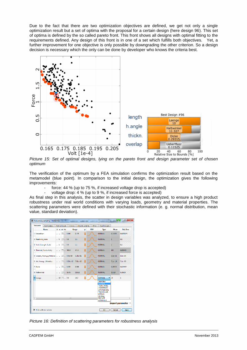
Due to the fact that there are two optimization objectives are defined, we get not only a single optimization result but a set of optima with the proposal for a certain design (here design 96). This set of optima is defined by the so called pareto front. This front shows all designs with optimal fitting to the requirements defined. Any design of this front is in one of a set which fulfills both objectives. Yet, a further improvement for one objective is only possible by downgrading the other criterion. So a design decision is necessary which the only can be done by developer who knows the criteria best.
Picture 15: Set of optimal designs, lying on the pareto front and design parameter set of chosen optimum The verification of the optimum by a FEA simulation confirms the optimization result based on the metamodel (blue point). In comparison to the initial design, the optimization gives the following improvements:
- force: 44 % (up to 75 %, if increased voltage drop is accepted) - voltage drop: 4 % (up to 9 %, if increased force is accepted)
As final step in this analysis, the scatter in design variables was analyzed, to ensure a high product robustness under real world conditions with varying loads, geometry and material properties. The scattering parameters were defined with their stochastic information (e. g. normal distribution, mean value, standard deviation).
Picture 16: Definition of scattering parameters for robustness analysis
CADFEM GmbH November 2013
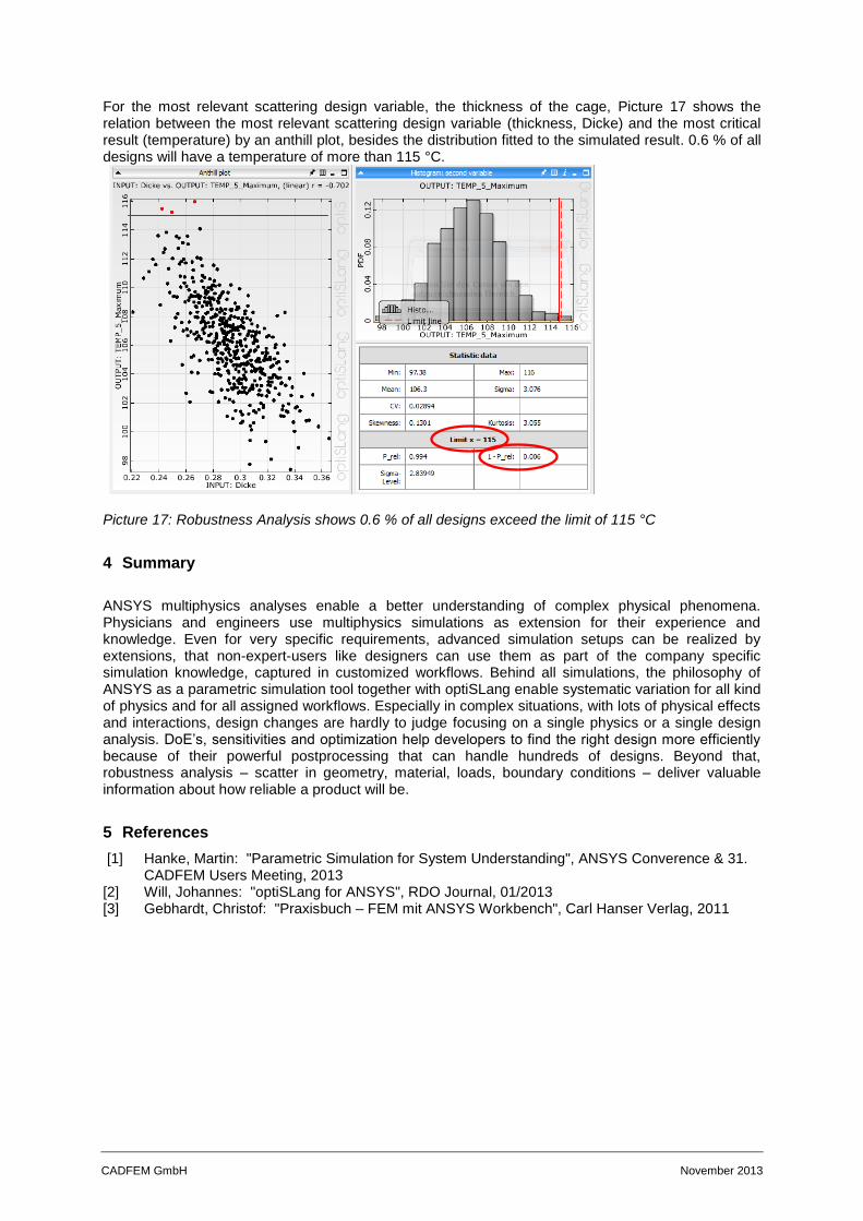
For the most relevant scattering design variable, the thickness of the cage, Picture 17 shows the relation between the most relevant scattering design variable (thickness, Dicke) and the most critical result (temperature) by an anthill plot, besides the distribution fitted to the simulated result. 0.6 % of all designs will have a temperature of more than 115 °C.
Picture 17: Robustness Analysis shows 0.6 % of all designs exceed the limit of 115 °C
4 Summary
ANSYS multiphysics analyses enable a better understanding of complex physical phenomena. Physicians and engineers use multiphysics simulations as extension for their experience and knowledge. Even for very specific requirements, advanced simulation setups can be realized by extensions, that non-expert-users like designers can use them as part of the company specific simulation knowledge, captured in customized workflows. Behind all simulations, the philosophy of ANSYS as a parametric simulation tool together with optiSLang enable systematic variation for all kind of physics and for all assigned workflows. Especially in complex situations, with lots of physical effects and interactions, design changes are hardly to judge focusing on a single physics or a single design analysis. DoE’s, sensitivities and optimization help developers to find the right design more efficiently because of their powerful postprocessing that can handle hundreds of designs. Beyond that, robustness analysis – scatter in geometry, material, loads, boundary conditions – deliver valuable information about how reliable a product will be.
5 References
[1] Hanke, Martin: "Parametric Simulation for System Understanding", ANSYS Converence & 31. CADFEM Users Meeting, 2013
[2] Will, Johannes: "optiSLang for ANSYS", RDO Journal, 01/2013 [3] Gebhardt, Christof: "Praxisbuch – FEM mit ANSYS Workbench", Carl Hanser Verlag, 2011