parametric study for seismic response of … · where necessary, aisc 2010 (ansi/aisc 341-10, 2010)...
TRANSCRIPT
BULETINUL INSTITUTULUI POLITEHNIC DIN IAŞI Publicat de
Universitatea Tehnică „Gheorghe Asachi” din Iaşi Tomul LXI (LXV), Fasc. 3, 2015
Secţia CONSTRUCŢII. ARHITECTURĂ
PARAMETRIC STUDY FOR SEISMIC RESPONSE OF DUAL
STEEL FRAMES WITH DISSIPATIVE STEEL PANELS
BY
CĂLIN NEAGU*, FLOREA DINU and DAN DUBINA
Politehnica Univeristy Timişoara, Romania
Department of Steel Structure and Structural Mechanics
Received: July 17, 2015 Accepted for publication: July 31, 2015
Abstract. Present study investigates the parametric response of dual steel
frames that consist of steel plate shear walls and moment resisting frames. The parametric study was carried out using a numerical model which was validated against experimental tests. Sap2000 was used to replicate the test results in order to validate the numerical models. The numerical model was applied to conduct incremental dynamic analyses on a 6 story SPSW frame in order to determine its seismic response. In the analysis two types of soil conditions and seven different ground motion records were taken into account. The main objective was to estimate the behaviour factor q, which is used in seismic design of such structures. Summary of investigations and main results will be presented.
Key words: dual frames; dissipative panels; nonlinear dynamic analysis; q factor.
1. Introduction The structural system using steel plate shear walls (SPSW) for lateral
resistance had a major development worldwide with the introduction of design rules in North American and Japanese codes. The lack of design provisions in *Corresponding author: e-mail: [email protected]
62 Călin Neagu, Florea Dinu and Dan Dubina
European seismic code EN 1998-1 made difficult the application of the system. In the absence of such design provisions, other design codes (e.g. AISC 2010 , (ANSI/AISC 341-10, 2010)) could be used as reference, but this is not very straightforward.
The economic cost and construction efficiency of the system represent two advantages of such structural systems. The detailing of the infill panel to bordering elements can be done using fillet welds or bolted connections. When bolted connections are used, the construction time may be reduced and there is a possibility of plate replacement after an earthquake. This represents a recent development in the field, where dissipative elements may be designed and detailed to be replaced after an earthquake (Dubina & Dinu, 2014). This requires special design and detailing conditions and may reduce the cost of intervention for low to moderate earthquakes. In most cases, replacement is conditioned by the re-centering capacity of the dual system.
In order to address the issues presented above with regard to the performances of SPSW systems, a research program, including experimental and numerical studies, was developed at Politehnica University Timisoara, Laboratory of Steel Structures. The experimental study was performed on dual SPSW systems in order to quantify the behavior factor q and to evaluate the re-centering capacity of the system. The numerical studies were performed on dual SPSW structures designed according to Eurocodes. Where necessary, AISC 2010 (ANSI/AISC 341-10, 2010) provisions were employed, also.
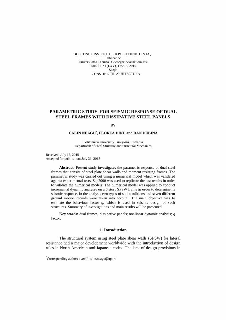
The study reported in this paper investigated the performance of a six story SPSW dual structure. The dual structural system used is composed of a moment resisting frame (MRF), two infill panels which are connected to the boundary elements with bolts, and two additional stanchions that are placed as interior vertical boundary elements (Fig. 1). This system allows the concentration of damage mainly in the plates. If the flexible MR frames are designed to remain elastic during the earthquake, they provide the restoring force that is necessary to re-center the structure and to allow the replacement of the damaged infill plates.
Infill plates
Link beam
Stanchions = +
Fig. 1 – Dual SPSW with MRF, infill plates and stanchions.
Non-linear dynamic analyses were employed taking into account two sets of ground motions scaled for two types of spectra corresponding to soft and
Bul. Inst. Polit. Iaşi, t. LXI (LXV), f. 3, 2015 63
stiff soil conditions given in EN1998-1. The numerical models were calibrated and validated against experimental data (Dubina & Dinu, 2014).
2. Parametric Study 2.1. Design of Structure
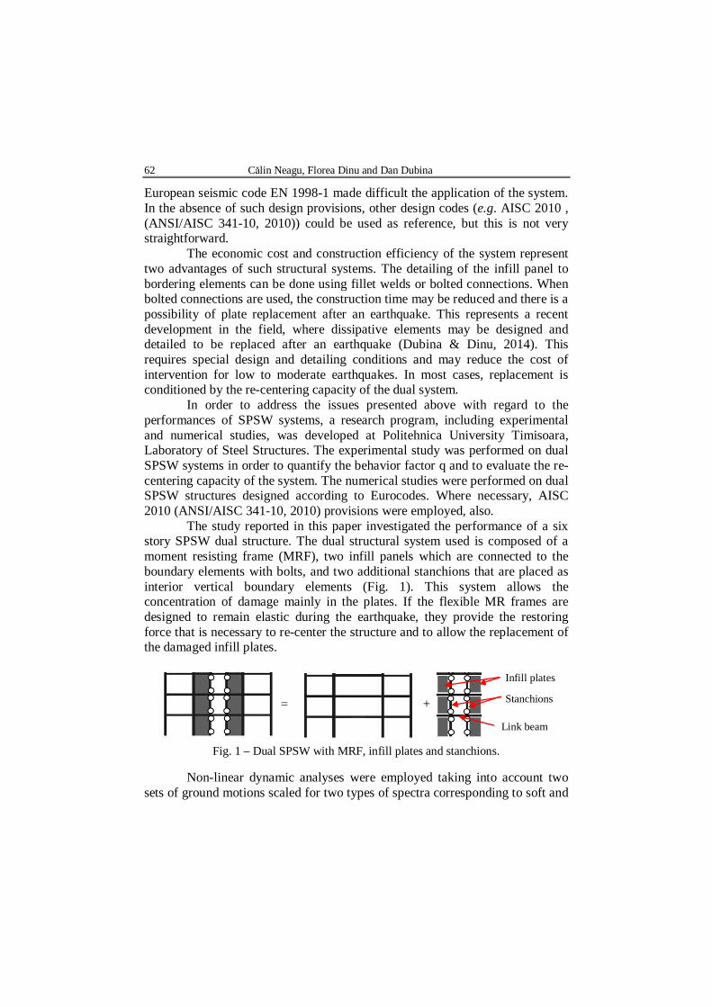
Design of the structure was done according to Eurocodes (EN1998-1; EN 1993-1-1; EN1993-1-8) and AISC (ANSI/AISC 341-10, 2010). According to EN1998-1, the building site is characterized by a peak ground acceleration of 0.4 g, with a corner period TC of 0.8 s (Type 1 response spectra and ground type D). A behavior factor of 5 was used for preliminary design of structure. The structure has the configuration presented in Fig. 2 a.
a b
Fig. 2 – a – SPSW structure; b – equivalent structure with tension diagonals.
According to AISC Seismic Provisions (ANSI/AISC 341-10, 2010),
SPSW is first approximated by a vertical truss with equivalent tension braces (Fig. 2 b). The cross sections of the equivalent braces need to be designed to meet the lateral drift requirements. According to the capacity design principles from AISC (ANSI/AISC 341-10, 2010), the horizontal and vertical boundary elements (HBE and VBE) are designed to resist the maximum forces developed under the tension field action of the fully yielded panels. Axial forces, shear forces, and bending moments develop in the SPSW boundary elements because of the overall overturning, shear, and tension field action in the panels. VBEs and HBEs should remain essentially elastic under the forces generated by fully yielded plates, but flexural hinges are allowed at the ends of HBEs. To prevent excessive deformation, leading to premature buckling under the pulling action of the plates, the minimum moment of inertia of the columns was calculated. After the equivalent structure with the vertical truss was designed and configured, the braces were replaced by steel panels. For an assumed angle of inclination α of the tension field (taken as 45°) and using the area of the equivalent braces, the thickness of the plates was calculated (Dubina & Dinu, 2014).
64 Călin Neagu, Florea Dinu and Dan Dubina
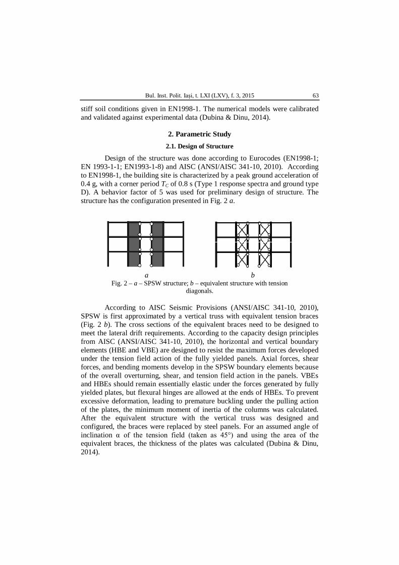
The geometry and section of frame members are shown in Fig. 3. The exterior bays measure 6 m, the interior bay measure 8 m and has two braced spans of 2.8 m long.
6 m 6 m
3.5 m m
2.8 2.4 2.8
IPE450
HEB
400
IPE450
2 mm
HEB
500
HEB
500
HEB
400
IPE500
HEB
400
Fig. 3 – Six story building frame.
The story height is 3.5 m. The beams, stanchions and columns were
designed using S355 steel, which has a nominal yield strength fy of 355 N/mm2. The plates were designed using S235 steel, which has a nominal yield strength fy of 235 N/mm2. European IPE and HEB hot rolled profiles were used for beams, columns and stanchions (see Fig. 3).
2.2. Analysis Procedure
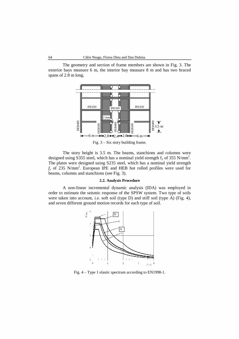
A non-linear incremental dynamic analysis (IDA) was employed in order to estimate the seismic response of the SPSW system. Two type of soils were taken into account, i.e. soft soil (type D) and stiff soil (type A) (Fig. 4), and seven different ground motion records for each type of soil.
Fig. 4 – Type 1 elastic spectrum according to EN1998-1.
A
D
Bul. Inst. Polit. Iaşi, t. LXI (LXV), f. 3, 2015 65
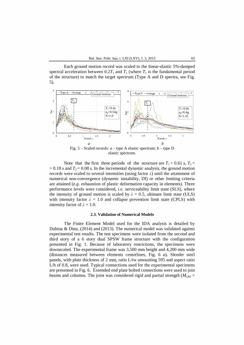
Each ground motion record was scaled to the linear-elastic 5%-damped spectral acceleration between 0.2T1 and T1 (where T1 is the fundamental period of the structure) to match the target spectrum (Type A and D spectra, see Fig. 5).
a b
Fig. 5 – Scaled records: a – type A elastic spectrum; b – type D elastic spectrum.
Note that the first three periods of the structure are T1 = 0.61 s, T2 =
= 0.18 s and T3 = 0.08 s. In the incremental dynamic analysis, the ground motion records were scaled to several intensities (using factor λ) until the attainment of numerical non-convergence (dynamic instability, DI) or other limiting criteria are attained (e.g. exhaustion of plastic deformation capacity in elements). Three performance levels were considered, i.e. serviceability limit state (SLS), where the intensity of ground motion is scaled by λ = 0.5, ultimate limit state (ULS) with intensity factor λ = 1.0 and collapse prevention limit state (CPLS) with intensity factor of λ = 1.0.
2.3. Validation of Numerical Models
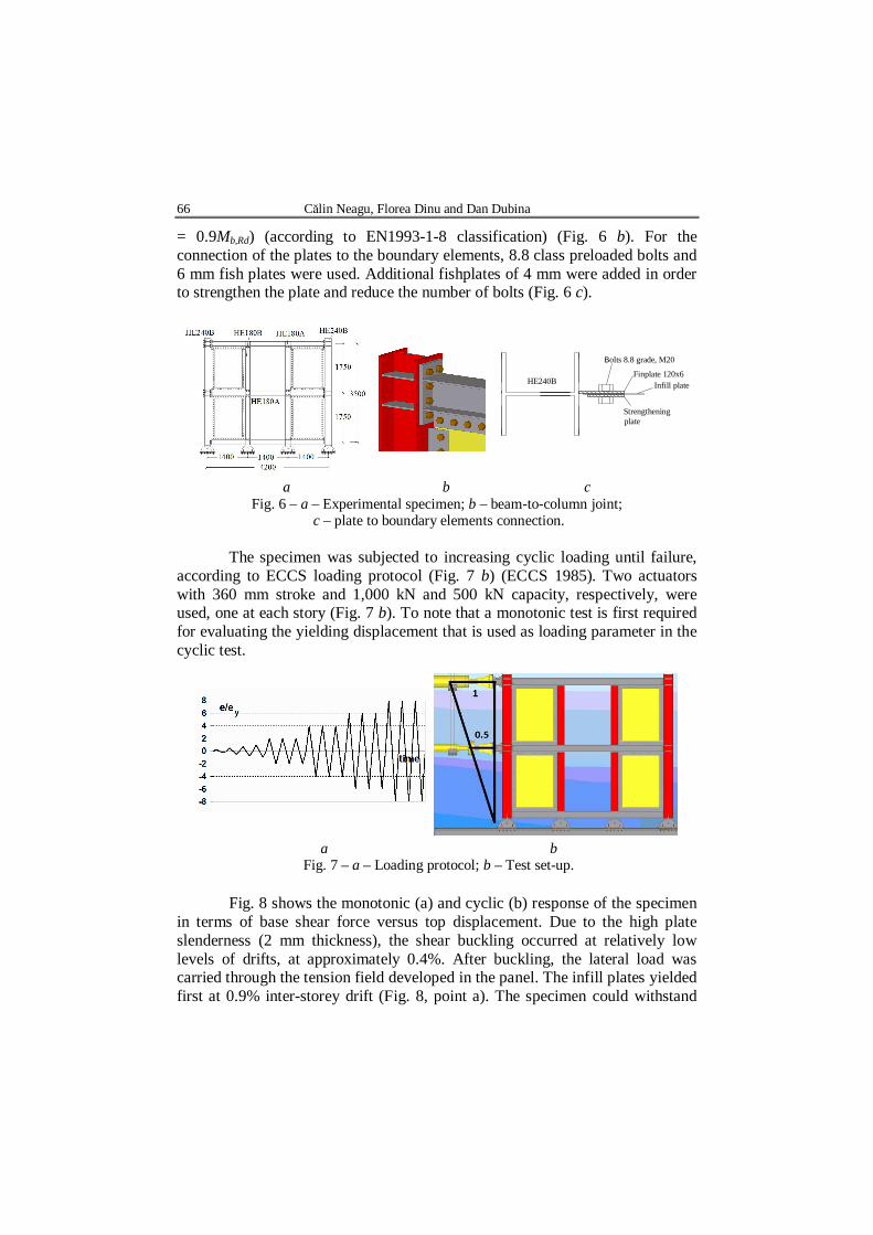
The Finite Element Model used for the IDA analysis is detailed by Dubina & Dinu, (2014) and (2013). The numerical model was validated against experimental test results. The test specimens were isolated from the second and third story of a 6 story dual SPSW frame structure with the configuration presented in Fig. 1. Because of laboratory restrictions, the specimens were downscaled. The experimental frame was 3,500 mm height and 4,200 mm wide (distances measured between elements centerlines, Fig. 6 a). Slender steel panels, with plate thickness of 2 mm, ratio L/tw amounting 595 and aspect ratio L/h of 0.8, were used. Typical connections used for the experimental specimens are presented in Fig. 6. Extended end plate bolted connections were used to join beams and columns. The joint was considered rigid and partial strength (Mj,Rd =
Tc=0.4s ag=0.54g S=1.0
Tc=0.8s ag=0.4g S=1.35
Ground motions Ground motions
T1 T1
66 Călin Neagu, Florea Dinu and Dan Dubina
= 0.9Mb,Rd) (according to EN1993-1-8 classification) (Fig. 6 b). For the connection of the plates to the boundary elements, 8.8 class preloaded bolts and 6 mm fish plates were used. Additional fishplates of 4 mm were added in order to strengthen the plate and reduce the number of bolts (Fig. 6 c).
Finplate 120x6
Strengtheningplate
Infill plate
Bolts 8.8 grade, M20
HE240B
a b c
Fig. 6 – a – Experimental specimen; b – beam-to-column joint; c – plate to boundary elements connection.
The specimen was subjected to increasing cyclic loading until failure,
according to ECCS loading protocol (Fig. 7 b) (ECCS 1985). Two actuators with 360 mm stroke and 1,000 kN and 500 kN capacity, respectively, were used, one at each story (Fig. 7 b). To note that a monotonic test is first required for evaluating the yielding displacement that is used as loading parameter in the cyclic test.
a b
Fig. 7 – a – Loading protocol; b – Test set-up.
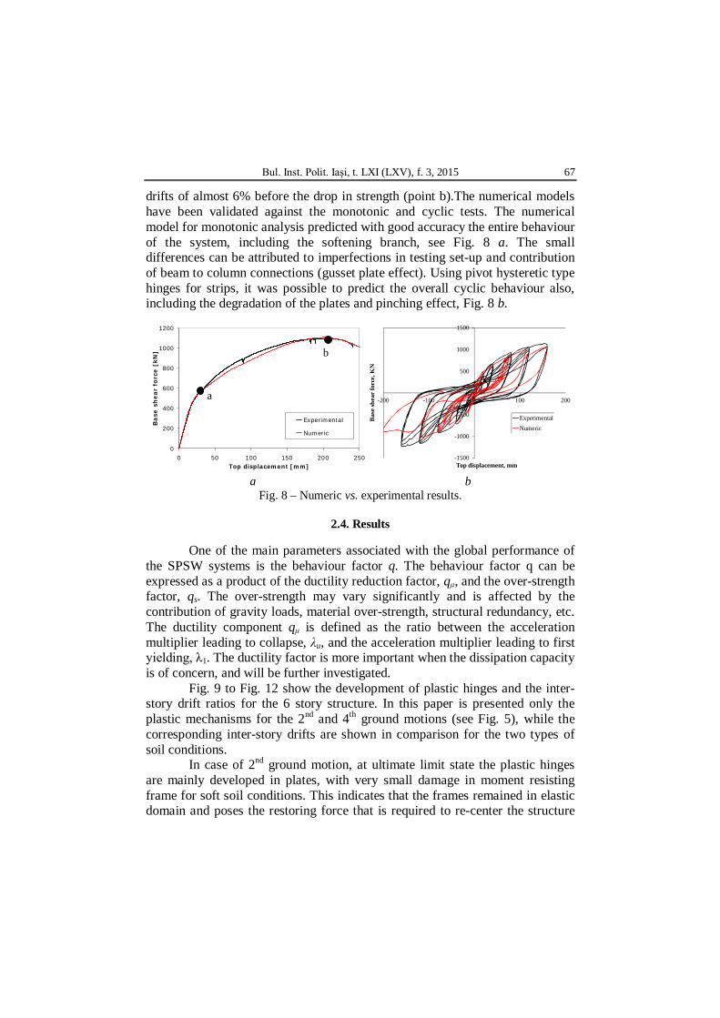
Fig. 8 shows the monotonic (a) and cyclic (b) response of the specimen in terms of base shear force versus top displacement. Due to the high plate slenderness (2 mm thickness), the shear buckling occurred at relatively low levels of drifts, at approximately 0.4%. After buckling, the lateral load was carried through the tension field developed in the panel. The infill plates yielded first at 0.9% inter-storey drift (Fig. 8, point a). The specimen could withstand
Bul. Inst. Polit. Iaşi, t. LXI (LXV), f. 3, 2015 67
drifts of almost 6% before the drop in strength (point b).The numerical models have been validated against the monotonic and cyclic tests. The numerical model for monotonic analysis predicted with good accuracy the entire behaviour of the system, including the softening branch, see Fig. 8 a. The small differences can be attributed to imperfections in testing set-up and contribution of beam to column connections (gusset plate effect). Using pivot hysteretic type hinges for strips, it was possible to predict the overall cyclic behaviour also, including the degradation of the plates and pinching effect, Fig. 8 b.
0
200
400
600
800
1000
1200
0 50 100 150 200 250Top displacement [mm]
Base
sh
ear
forc
e [
kN
]
Experimental
Numeric
-1500
-1000
-500
0
500
1000
1500
-200 -100 0 100 200
Bas
e sh
ear
forc
e, K
N
Top displacement, mm
ExperimentalNumeric
a b
Fig. 8 – Numeric vs. experimental results.
2.4. Results
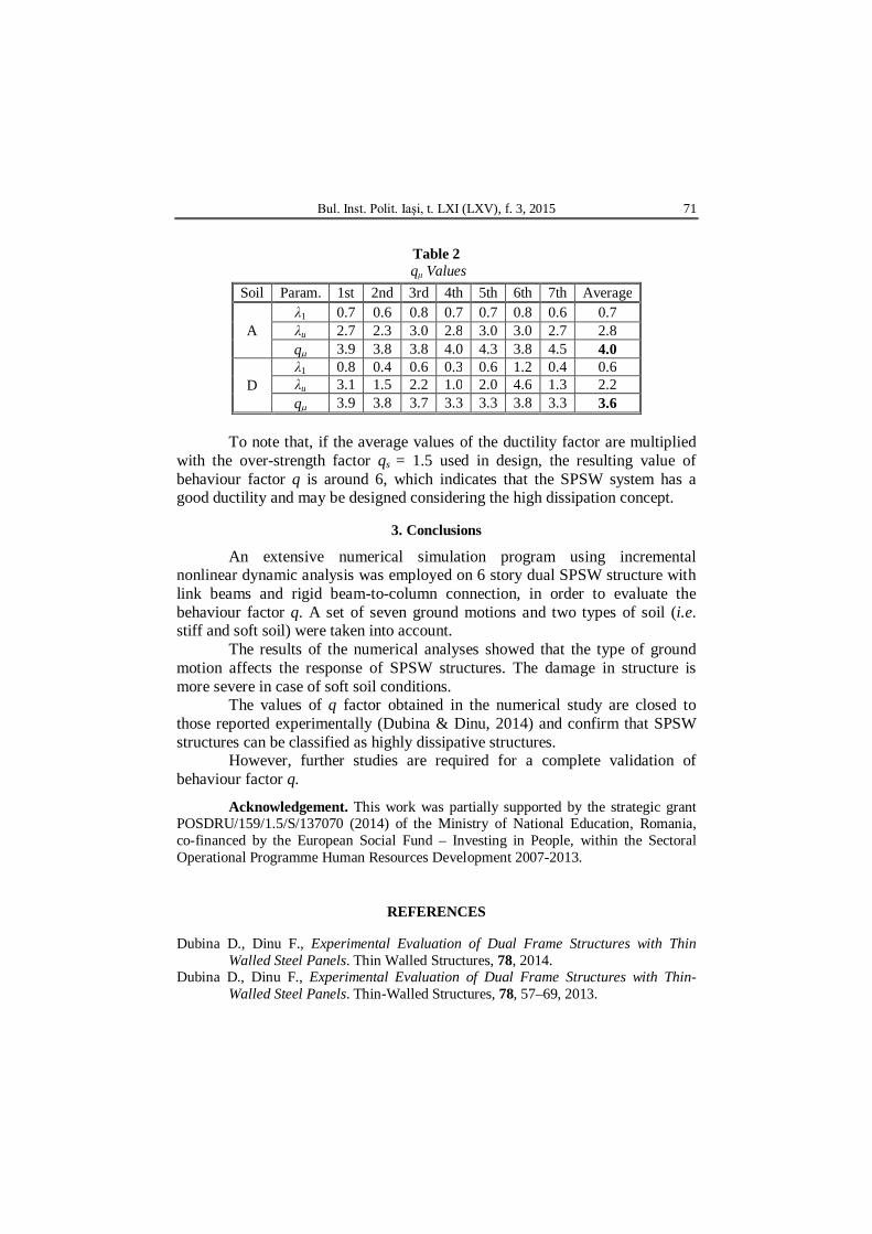
One of the main parameters associated with the global performance of the SPSW systems is the behaviour factor q. The behaviour factor q can be expressed as a product of the ductility reduction factor, qμ, and the over-strength factor, qs. The over-strength may vary significantly and is affected by the contribution of gravity loads, material over-strength, structural redundancy, etc. The ductility component qμ is defined as the ratio between the acceleration multiplier leading to collapse, λu, and the acceleration multiplier leading to first yielding, λ1. The ductility factor is more important when the dissipation capacity is of concern, and will be further investigated.
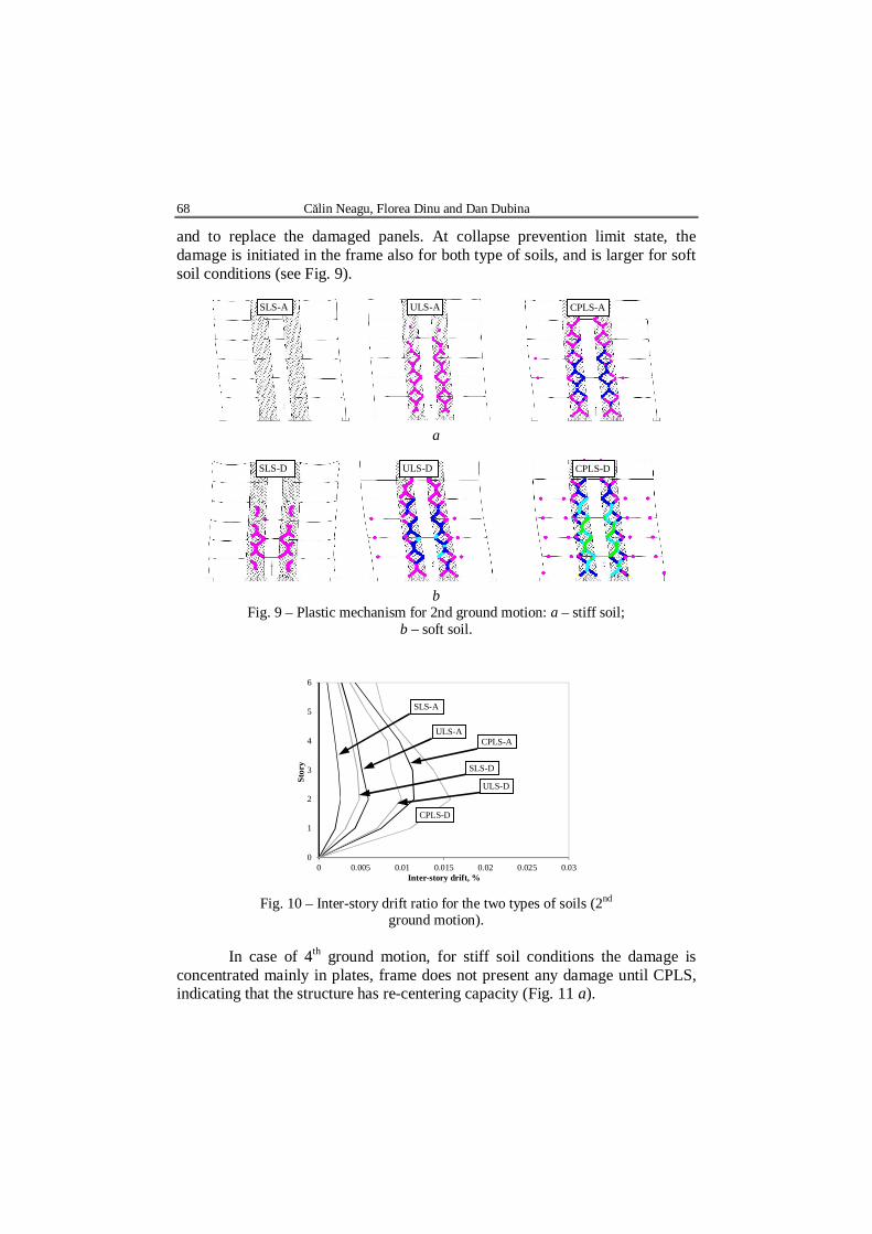
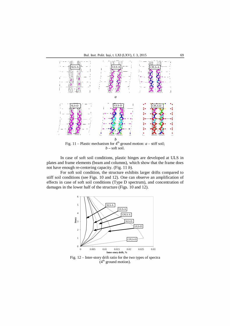
Fig. 9 to Fig. 12 show the development of plastic hinges and the inter-story drift ratios for the 6 story structure. In this paper is presented only the plastic mechanisms for the 2nd and 4th ground motions (see Fig. 5), while the corresponding inter-story drifts are shown in comparison for the two types of soil conditions.
In case of 2nd ground motion, at ultimate limit state the plastic hinges are mainly developed in plates, with very small damage in moment resisting frame for soft soil conditions. This indicates that the frames remained in elastic domain and poses the restoring force that is required to re-center the structure
a
b
68 Călin Neagu, Florea Dinu and Dan Dubina
and to replace the damaged panels. At collapse prevention limit state, the damage is initiated in the frame also for both type of soils, and is larger for soft soil conditions (see Fig. 9).
a
b
Fig. 9 – Plastic mechanism for 2nd ground motion: a – stiff soil; b – soft soil.
0
1
2
3
4
5
6
0 0.005 0.01 0.015 0.02 0.025 0.03
Stor
y
Inter-story drift, %
ULS-A
SLS-A
CPLS-A
SLS-D
ULS-D
CPLS-D
Fig. 10 – Inter-story drift ratio for the two types of soils (2nd
ground motion).
In case of 4th ground motion, for stiff soil conditions the damage is concentrated mainly in plates, frame does not present any damage until CPLS, indicating that the structure has re-centering capacity (Fig. 11 a).
SLS-D ULS-D CPLS-D
CPLS-A ULS-A SLS-A
Bul. Inst. Polit. Iaşi, t. LXI (LXV), f. 3, 2015 69
a
b
Fig. 11 – Plastic mechanism for 4th ground motion: a – stiff soil; b – soft soil.
In case of soft soil conditions, plastic hinges are developed at ULS in
plates and frame elements (beam and columns), which show that the frame does not have enough re-centering capacity. (Fig. 11 b).
For soft soil condition, the structure exhibits larger drifts compared to stiff soil conditions (see Figs. 10 and 12). One can observe an amplification of effects in case of soft soil conditions (Type D spectrum), and concentration of damages in the lower half of the structure (Figs. 10 and 12).
0
1
2
3
4
5
6
0 0.005 0.01 0.015 0.02 0.025 0.03
Stor
y
Inter-story drift, %
ULS-A SLS-A
CPLS-A
SLS-D
ULS-D
CPLS-D
Fig. 12 – Inter-story drift ratio for the two types of spectra
(4th ground motion).
CPLS-A ULS-A SLS-A
SLS-D ULS-D CPLS-D

70 Călin Neagu, Florea Dinu and Dan Dubina
Table 1 present the plastic rotations in hinges developed in beams (B) and columns (C) at the three limit states for the two ground motions presented above (2nd and 4th).
Table 1 Plastic Hinges Values for the Two Ground Motions
Soil Level 2nd acc. 4th acc. B C B C
A SLS – – – – ULS – – – –
CPLS 0.002 0.001 0.003 0.001
B SLS – – – – ULS 0.004 0.002 - 0.016
CPLS DI DI DI DI Note: B – beams; C- column; DI – dynamic instability.
Fig. 13 shows the incremental dynamic analysis curves in terms of
inter-story drift ratios and acceleration multipliers for the structure for the two types of soil conditions considered in this study.
In case of ground motions scaled to type D spectrum, the structure attains the collapse criteria before reaching collapse prevention limit state for 3 ground motions (2nd, 4th and 7th). In case of ground motions scaled to type A spectrum, the structures attain the collapse criteria well after collapse prevention limit state.
Table 2 shows the individual values for each ground motion and the average value of the ductility component, qμ, per type of spectrum. For stiff soil conditions (type A spectrum), the average value of the ductility factor is 4.0, while for soft soil conditions (type D spectrum), qμ amounts 3.6. The type of ground motion influences the yielding and the ultimate value of the acceleration but the effect on qμ factor is not very significant.
D soil
1st
6th
7th 5th
4th
3rd
2nd
4th
2nd
5th 6th
1st
3rd
7th
A soil
Fig. 13 – IDA curves for ground motions scaled to type A and D spectra.
Bul. Inst. Polit. Iaşi, t. LXI (LXV), f. 3, 2015 71
Table 2
qμ Values Soil Param. 1st 2nd 3rd 4th 5th 6th 7th Average
A λ1 0.7 0.6 0.8 0.7 0.7 0.8 0.6 0.7 λu 2.7 2.3 3.0 2.8 3.0 3.0 2.7 2.8 q 3.9 3.8 3.8 4.0 4.3 3.8 4.5 4.0
D λ1 0.8 0.4 0.6 0.3 0.6 1.2 0.4 0.6 λu 3.1 1.5 2.2 1.0 2.0 4.6 1.3 2.2 q 3.9 3.8 3.7 3.3 3.3 3.8 3.3 3.6
To note that, if the average values of the ductility factor are multiplied
with the over-strength factor qs = 1.5 used in design, the resulting value of behaviour factor q is around 6, which indicates that the SPSW system has a good ductility and may be designed considering the high dissipation concept.
3. Conclusions
An extensive numerical simulation program using incremental nonlinear dynamic analysis was employed on 6 story dual SPSW structure with link beams and rigid beam-to-column connection, in order to evaluate the behaviour factor q. A set of seven ground motions and two types of soil (i.e. stiff and soft soil) were taken into account.
The results of the numerical analyses showed that the type of ground motion affects the response of SPSW structures. The damage in structure is more severe in case of soft soil conditions.
The values of q factor obtained in the numerical study are closed to those reported experimentally (Dubina & Dinu, 2014) and confirm that SPSW structures can be classified as highly dissipative structures.
However, further studies are required for a complete validation of behaviour factor q.
Acknowledgement. This work was partially supported by the strategic grant POSDRU/159/1.5/S/137070 (2014) of the Ministry of National Education, Romania, co-financed by the European Social Fund – Investing in People, within the Sectoral Operational Programme Human Resources Development 2007-2013.
REFERENCES Dubina D., Dinu F., Experimental Evaluation of Dual Frame Structures with Thin
Walled Steel Panels. Thin Walled Structures, 78, 2014. Dubina D., Dinu F., Experimental Evaluation of Dual Frame Structures with Thin-
Walled Steel Panels. Thin-Walled Structures, 78, 57–69, 2013.

72 Călin Neagu, Florea Dinu and Dan Dubina
Neagu C., Multi-Storey Building Frames Stiffened with Dissipative Shear Walls. Ph. D. Diss., Univ. Politehnica Timişoara, Romania, 2011.
Vamvatsikos D., Cornell C.A., Incremental Dynamic Analysis. Earthquake Engng. a. Struct. Dynam., 31, 3, 491–514 (2002).
* * * ANSI/AISC 341-10, Seismic Provisions for Structural Steel Buildings. Amer. Inst. for Steel Constr., 2010.
* * * ECCS 1985, Recommended Testing Procedures for Assessing the Behavior of Structural Elements under Cyclic Loads. European Convention for Constructional Steelwork. Technical Committee 1, TWG 1.3 – Seismic Design, No.45, 1985.
* * * Eurocode 3: Design of Steel Structures. Part 1-1: General Rules and Rules for Buildings. EN 1993-1-1, CEN, 2005.
* * * Eurocode 8: Design of Structures for Earthquake Resistance. Part 1: General Rules, Seismic Actions and Rules for Buildings. EN 1998-1, CEN, 2004.
* * * Eurocode 3: Design of Steel Structures. Part 1-8: Design of Joints. EN1993-1-8, CEN, 2005.
STUDIU PARAMETRIC PENTRU RĂSPUNSUL SEISMIC AL CADRELOR DUALE DE OŢEL CU PANOURI DISIPATIVE DIN OŢEL
(Rezumat)
Se investighează răspunul parametric al cadrelor duale de oţel formate din
cadre necontravântuite şi panouri de forfecare din oţel (SPSW). Studiul parametric a fost efectuat folosind un model numeric validat cu ajutorul
unor teste experimentale. Sap2000 a fost folosit pentru a calibra rezultatele testelor în vederea validării modelului numeric. Acest model a fost folosit pentru efectuarea unor analize dinamice incrementale pe un cadru SPSW cu 6 nivele în vederea determinării răspunsului seismic. În aceste analize au fost luate în considerare două tipuri de teren şi şapte accelerograme diferite. Obiectivul principal l-a constituit estimarea factorului de comportare q, care este folosit în proiectarea seismică curentă al acestui tip de structuri. Rezultatele principale sunt prezentate pe scurt.