parker autoclave engineers vft - rg-group.com full... · autoclave a reputation for reliable and...
TRANSCRIPT

Valves, Fittings and TubingPressures to 150,000 psi (10,000 bar)
Parker Autoclave Engineers: Fluid Components Product CatalogFebruary 2013

All general terms and conditions of sale, including limitations of our liability, apply to all products and services sold. 1
Needle Valves - 10V & SW Series
Low PressureNeedle Valves
Pressures to 15,000 psi (1034 bar)
10V & SW SeriesLow Pressure
Since 1945 Parker Autoclave Engineers has designed and built premium quality valves, fittings and tubing. This commitment to engineering and manufacturing excellence has earned Parker Autoclave a reputation for reliable efficient product performance. Parker Autoclave Engineers has long been established as the world leader in high pressure fluid handling components for the chemical/petrochemical, research, and oil and gas industries.
Low Pressure Valve Features:• 10V Series valve design provides in-line tube connections for 1/4” to 1/2” tube sizes.• SW Series valve design provides increased flow capabilities.• Tubing sizes from 1/8” to 1/2”.• Rising stem/barstock body design.• Non-rotating stem prevents stem/seat galling.• Metal-to-metal seating achieves bubble-tight shut- off, longer stem/seat life in abrasive flow, greater durability for repeated on/off cycles and excellent corrosion resistance.• PTFE encapsulated packing provides dependable stem and body sealing.• Stem sleeve and packing gland materials have been selected to achieve extended thread cycle life and reduced handle torque. • Choice of Vee or Regulating stem tips.• Available in five body patterns.
Parker Autoclave Engineers valves are complemented by a complete line of low pressure fittings, tubing, check valves and line filters. The 10V and SW series use Parker Autoclave Engineers' SpeedBite connection. This single-ferrule compression sleeve connection delivers fast, easy make-up and reliable bubble-tight performance in liquid or gas service.
www.autoclave.com

All general terms and conditions of sale, including limitations of our liability, apply to all products and services sold.2
Valve Series - 10V SeriesPressures to 15,000 psi (1034 bar)
Tube Pressure Outside Rating Diameter Orifice psi (bar) Size Connection Size Rated @ Room Inches Type Inches (mm) Cv* Temperature** 1/8 W125 0.094 (2.39) 0.12 15,000 (1034) 1/4 W250 0.125 (3.18) 0.20 15,000 (1034) 3/8 W375 0.125 (3.18) 0.20 15,000 (1034) 1/2 SW500 0.250 (6.35) 0.86 10,000 (690)
Notes: * CV values shown are for 2-way straight valve pattern. For 2-way angle patterns, increase CV value 50%. (Based on water)
** For complete temperature ratings see pressure/temperature rating guide in Technical Information section.
To ensure proper fit use Autoclave tubing
Generalized Flow Coefficient Curves (Cv)
% of rated Cv
Nu
mb
er o
f tu
rns
op
en
10 20 30 40 50 60 70 80 90 100
7
6
5
4
3
2
1
0
Regulating Stem
Vee Stem
Ordering ProcedureFor complete information on available stem types, optional connections and additional valve options, see Needle Valve Options section or contact your Sales Representative. 10V Series valves are furnished complete with connection components, unless otherwise specified.
Typical catalog number: 10V4071
2-1/8”4-1/4”6-3/8”8-1/2”
07 - non-rotating Vee stem (on-off service) 08 - non-rotating regulating stem (tapered tip for regulating and shutoff) 87 - Vee stem with replaceable seat 88 - Regulating stem with replaceable seat
1 - two-way straight2 - two-way angle3 - three-way, two on pressure4 - three-way, one on pressure5 - three-way, two stem manifold valve
For extreme temperature and other
options, see Valve Options.
XXOptions
1Body
Pattern
07Stem/Seat
Type
4Outside Diameter
Tube Size
10VValveSeries
LOW FRICTION ALUMINUM BRONZE PACKING GLAND
COLD WORKED TYPE 316 SS BODY IN FIVE PATTERNS
NON-ROTATINGSTEM
ADJUSTABLE PACKINGBELOW THREADS
LOCKING DEVICE
SPEEDBITE "W" CONNECTIONS (EXCEPT 1/2" SPEEDBITE SW)
METAL-TO-METAL SEATING
CHOICE OF VEE OR REGULATING STEM TIP
ANTI-EXTRUSIONBACK-UP RINGS
POWDER COATEDSTAINLESS STEELHANDLE
Note: Contact Sales for 1/16”tube size or see MVE Series.

All general terms and conditions of sale, including limitations of our liability, apply to all products and services sold. 3
3-Way / 2 on Pressure
2-Way Angle
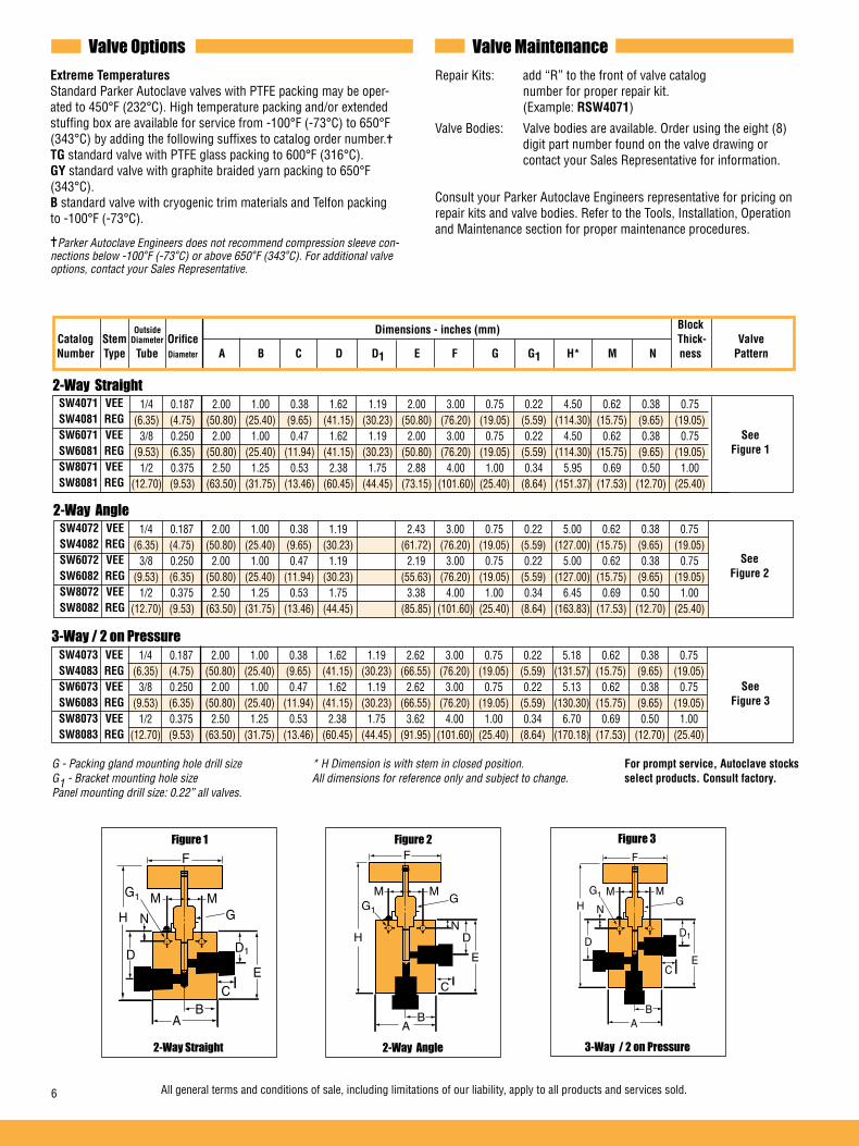
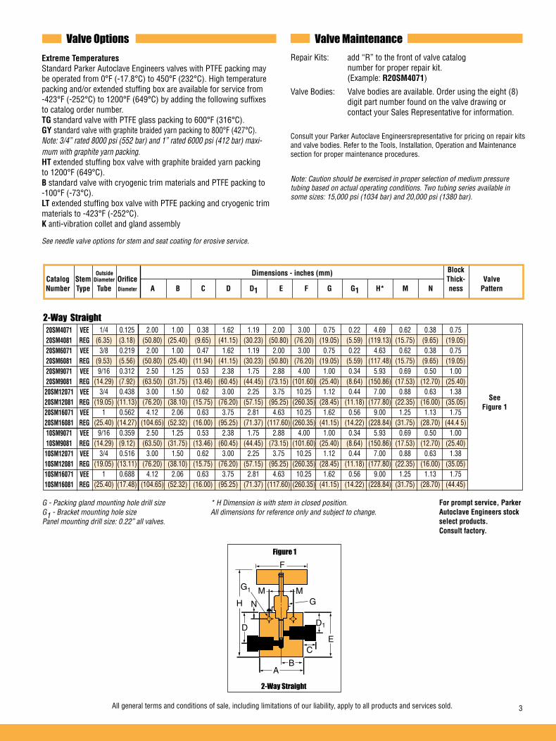
Valve Options Valve MaintenanceExtreme Temperatures Standard Parker Autoclave valves with PTFE packing may be operated to 450°F (232°C). High temperature packing and/or extended stuffing box is available for service from -100°F (-73°C) to 650°F (343°C) by adding the following suffixes to catalog order number.TG standard valve with PTFE glass packing to 600°F (316°C).GY standard valve with graphite braided yarn packing to 650°F (343°C).B standard valve with cryogenic trim materials and Telfon packing to -100°F (-73°C).
Parker Autoclave Engineers does not recommend compression sleeve con-nections below -100°F (-73°C) or above 650°F (343°C). For additional valve options, contact your Sales Representative.
Repair Kits: add “R” to the front of valve catalog number for proper repair kit. (Example: R10V4071)Valve Bodies: Valve bodies are available. Order using the eight (8) digit part number found on the valve drawing or contact your Sales Representative for information.Consult your Parker Autoclave Engineers representative for pricing on repair kits and valve bodies. Refer to the Tools, Installation, Operation and Maintenance section for proper maintenance procedures.
10V2073 VEE 10V2083 REG 10V4073 VEE 10V4083 REG 10V6073 VEE 10V6083 REG 10V8073 VEE 10V8083 REG
1/8** 0.094 1.50 0.75 0.31 1.06 0.81 1.69 3.00 0.62 0.17 4.06 0.56 0.31 0.62 (3.18) (2.39) (38.10) (19.05) (7.87) (26.92) 20.57 (42.93) (76.20) (15.75) (4.32) (103.12) (12.70) (7.87) (15.75) 1/4 0.125 2.00 1.00 0.56 1.19 2.19 3.00 0.97 0.22 4.81 0.69 0.38 1.00 (6.35) (3.18) (50.80) (25.40) (14.22) (30.23) (55.63) (76.20) (24.64) (5.59) (122.17) (17.53) (9.65) (25.40) 3/8 0.125 2.00 1.00 0.62 1.19 2.19 3.00 0.97 0.22 4.81 0.69 0.38 1.00 (9.53) (3.18) (50.80) (25.40) (15.75) (30.23) (55.63) (76.20) (24.64) (5.59) (122.17) (17.53) (9.65) (25.40) 1/2 0.250 2.50 1.25 0.53 1.19 2.44 3.00 0.97 0.22 5.06 0.69 0.38 1.00 (12.70) (6.35) (63.50) (31.75) (13.46) (30.23) (61.98) (76.20) (24.64) (5.59) (128.52) (17.53) (9.65) (25.40)
10V2072 VEE 10V2082 REG 10V4072 VEE 10V4082 REG 10V6072 VEE 10V6082 REG 10V8072 VEE 10V8082 REG
1/8 0.094 1.50 0.75 0.31 0.81 1.56 3.00 0.62 0.17 3.94 0.56 0.31 0.62 (3.18) (2.39) (38.1) (19.05) (7.87) (20.57) (39.62) (76.20) (15.75) (4.32) (100.08) (12.70) (7.87) (15.75) 1/4 0.125 2.00 1.00 0.56 1.19 2.19 3.00 0.97 0.22 4.81 0.69 0.31 1.00 (6.35) (3.18) (50.80) (25.40) (14.2) (30.23) (55.63) (76.20) (24.64) (5.59) (122.17) (17.53) (7.87) (25.40) 3/8 0.125 2.00 1.00 0.62 1.19 2.19 3.00 0.97 0.22 4.81 0.69 0.31 1.00 (9.53) (3.18) (50.80) (25.40) (15.7) (30.23) (55.63) (76.20) (24.64) (5.59) (122.17) (17.53) (7.87) (25.40) 1/2 0.250 2.50 1.25 0.53 1.25 2.50 3.00 0.97 0.22 5.06 0.69 0.38 1.00 (12.70) (6.35) (63.50) (31.75) (13.5) (31.75) (63.50) (76.20) (24.64) (5.59) (128.52) (17.53) (9.65) (25.40)
2-Way Straight 10V2071 VEE 10V2081 REG 10V4071 VEE 10V4081 REG 10V6071 VEE 10V6081 REG 10V8071 VEE 10V8081 REG
1/8** 0.094 1.50 0.75 0.31 1.06 0.81 1.38 3.00 0.62 0.17 3.75 0.56 0.31 0.62 (3.18) (2.39) (38.10) (19.05) (7.87) (26.92) (20.57) (35.05) (76.20) (15.75) (4.32) (95.25) (14.22) (7.87) (15.75) 1/4 0.125 2.00 1.00 0.56 1.19 1.69 3.00 0.97 0.22 4.44 0.69 0.38 1.00 (6.35) (3.18) (50.80) (25.40) (14.22) (30.23) (42.93) (76.20) (24.64) (5.59) (112.78) (17.53) (9.65) (25.40) 3/8 0.125 2.00 1.00 0.62 1.19 1.69 3.00 0.97 0.22 4.31 0.69 0.38 1.00 (9.53) (3.18) (50.80) (25.40) (15.75) (30.23) (42.93) (76.20) (24.64) (5.59) (109.47) (17.53) (9.65) (25.40) 1/2 0.250 2.50 1.25 0.53 1.25 1.81 3.00 0.97 0.22 4.44 0.69 0.38 1.00 (12.70) (6.35) (63.50) (31.75) (13.46) (31.75) (45.97) (76.20) (24.64) (5.59) (112.78) (17.53) (9.65) (25.40)
G - Packing gland mounting hole drill size * H Dimension is with stem in closed position. For prompt service, Autoclave stocksG1 - Bracket mounting hole size ** 1/8” straight and 3-Way/2 on pressure valves have offset select products. Consult factory.Panel mounting drill size: 0.22” all valves. tube connections. All dimensions for reference only and subject to change.
Dimensions - inches (mm)Outside
H
F
G1
G
D
E
A
M
C
B
M
N
H
F
G1G
D1
E
A
C
B
M M
N
DH N
M M
F
G1
G
D1DE
BA
C
2-Way Angle 3-Way / 2 on Pressure2-Way Straight
Figure 3Figure 2Figure 1
See Figure 1
See Figure 2
See Figure 3
Block Catalog Stem Diameter Orifice Thick- Number Type Tube Diameter A B C D D1 E F G G1 H* M N ness
Valve Pattern

All general terms and conditions of sale, including limitations of our liability, apply to all products and services sold.4
3-Way / 2-Stem Manifold
2-Way Angle / Replaceable Seat
3-Way / 1 on Pressure
G - Packing gland mounting hole drill size * H Dimension is with stem in closed position. For prompt service, Autoclave G1 - Bracket mounting hole size All dimensions for reference only and subject to change. stocks select products. Panel mounting drill size: 0.22” all valves. Consult factory.
10V2075 VEE 10V2085 REG 10V4075 VEE 10V4085 REG 10V6075 VEE 10V6085 REG 10V8075 VEE 10V8085 REG
1/8 0.094 1.50 0.75 0.31 1.12 0.81 2.25 3.00 0.62 0.17 4.63 0.56 0.31 0.62 (3.18) (2.39) (38.10) (19.05) (7.87) (28.45) (20.57) (57.15) (76.20) (15.75) (4.32) (117.60) (12.70) (7.87) (15.7) 1/4 0.125 2.00 1.00 0.56 1.69 1.09 3.38 3.00 0.97 0.22 5.82 0.69 0.38 1.00 (6.35) (3.18) (50.80) (25.40) (14.22) (42.93) (27.69) (85.85) (76.20) (24.64) (5.59) (147.83) (17.53) (9.65) (25.40) 3/8 0.125 2.00 1.00 0.62 1.69 1.09 3.38 3.00 0.97 0.22 5.82 0.69 0.38 1.00 (9.53) (3.18) (50.80) (25.40) (15.75) (42.93) (27.69) (85.85) (76.20) (24.64) (5.59) (147.83) (17.53) (9.65) (25.40) 1/2 0.250 2.50 1.25 0.53 1.69 1.03 3.38 3.00 0.97 0.22 5.82 0.69 0.38 1.00 (12.70) (6.35) (63.50) (31.75) (13.46) (42.93) (26.16) (85.85) (76.20) (24.64) (5.59) (147.83) (17.53) (9.65) (25.40)
10V2872 VEE 10V2882 REG 10V4872 VEE 10V4882 REG 10V6872 VEE 10V6882 REG 10V8872 VEE 10V8882 REG
1/8 0.094 1.50 0.75 0.31 0.81 1.28 1.56 3.00 0.62 0.17 4.50 0.56 0.31 0.62 (3.18) (2.39) (38.10) (19.05) (7.87) (20.57) (32.51) (39.62) (76.20) (15.75) (4.32) (114.30) (12.70) (7.87) (15.75) 1/4 0.125 2.00 1.00 0.56 1.12 2.13 2.25 3.00 0.97 0.22 6.00 0.69 0.38 1.00 (6.35) (3.18) (50.80) (25.40) (14.22) (28.45) (54.10) (57.15) (76.20) (24.64) (5.59) (152.40) (17.53) (9.65) (25.40) 3/8 0.125 2.00 1.00 0.62 1.12 2.28 2.25 3.00 0.97 0.22 6.00 0.69 0.38 1.00 (9.53) (3.18) (50.80) (25.40) (15.75) (28.45) (57.91) (57.15) (76.20) (24.64) (5.59) (152.40) (17.53) (9.65) (25.40) 1/2 0.250 2.50 1.25 0.53 1.00 2.50 2.38 3.00 0.97 0.28 6.06 0.69 0.38 1.00 (12.70) (6.35) (63.50) (31.75) (13.46) (25.45) (63.50) (60.45) (76.20) (24.64) (7.11) (153.92) (17.53) (9.65) (25.40)
10V2074 VEE 10V2084 REG 10V4074 VEE 10V4084 REG 10V6074 VEE 10V6084 REG 10V8074 VEE 10V8084 REG
1/8 0.094 1.50 0.75 0.31 0.81 1.56 3.00 0.62 0.17 3.94 0.56 0.31 0.62 (3.18) (2.39) (38.1) (19.05) (7.87) (20.57) (39.62) (76.20) (15.75) (4.32) (100.08) (12.70) (7.87) (15.7) 1/4 0.125 2.00 1.00 0.56 1.19 2.19 3.00 0.97 0.22 4.81 0.69 0.38 1.00 (6.35) (3.18) (50.8) (25.40) (14.22) (30.23) (55.63) (76.20) (24.64) (5.59) (122.17) (17.53) (9.65) (25.40) 3/8 0.125 2.00 1.00 0.62 1.19 2.19 3.00 0.97 0.22 4.81 0.69 0.38 1.00 (9.53) (3.18) (50.8) (25.40) (15.75) (30.23) (55.63) (76.20) (24.64) (5.59) (122.17) (17.53) (9.65) (25.40) 1/2 0.250 2.50 1.25 0.53 1.19 2.44 3.00 0.97 0.22 5.06 0.69 0.38 1.00 (12.70) (6.35) (63.5) (31.75) (13.46) (30.23) (61.98) (76.20) (24.64) (5.59) (128.52) (17.53) (9.65) (25.40)
Dimensions - inches (mm)Outside
H N
M M
F
G1
G
DDE
C
BA
3-Way / 1 on Pressure
Figure 4
H
N
M M
F
G1
G
D
E
C
BA
C
D1
H N
M M
F
G1
G
D1
E
C
BA
D1
D
2-Way Angle / Replaceable Seat 3-Way / 2-Stem Manifold
Figure 6Figure 5
See Figure 6
See Figure 5
See Figure 4
Block Catalog Stem Diameter Orifice Thick- Number Type Tube Diameter A B C D D1 E F G G1 H* M N ness
Valve Pattern

All general terms and conditions of sale, including limitations of our liability, apply to all products and services sold. 5
Needle Valves - SW SeriesPressures to 15,000 psi (1034 bar)
Tube Pressure Outside Rating Diameter Orifice psi (bar) Size Connection Size Rated @ Room Inches Type Inches (mm) Cv* Temperature** 1/8 W125 — Refer to 10V Series Valves — 1/4 SW250 0.188 (4.77) 0.65 15,000 (1034) 3/8 SW375 0.250 (6.35) 0.95 15,000 (1034) 1/2 SW500 0.375 (9.52) 1.90 10,000 (690)
Notes: * CV values shown are for 2-way straight valve pattern. For 2-way angle patterns, increase CV value 50%. (Based on water)
** For complete temperature ratings see pressure/temperature rating guide in Technical Information section.
To ensure proper fit use Autoclave tubing
Generalized Flow Coefficient Curves (Cv)
% of rated Cv
Nu
mb
er o
f tu
rns
op
en
10 20 30 40 50 60 70 80 90 100
7
6
5
4
3
2
1
0
Regulating Stem
Vee Stem
Ordering ProcedureFor complete information on available stem types, optional connections and additional valve options, see Needle Valve Options section or contact your Sales Representative. SW Series valves are furnished complete with connection components, unless otherwise specified.
Typical catalog number: SW4071
4-1/4”6-3/8”8-1/2”
07 - non-rotating Vee stem (on off service)08 - non-rotating regulating stem (tapered tip for regulating and shutoff)87 - Vee stem with replaceable seat88 - Regulating stem with replaceable seat
1 - two-way straight2 - two-way angle3 - three-way, two on pressure4 - three-way, one on pressure5 - three-way, two stem manifold valve
For extreme temperature and other
options, see Valve Options.
XXOptions
1Body
Pattern
07Stem/Seat
Type
4Outside Diameter
Tube Size
SWValveSeries
LOCKING DEVICE
NON-ROTATINGSTEM
ADJUSTABLE PACKING BELOW THREADS
SPEEDBITE "SW" TUBE CONNECTIONS(except 1/8" SpeedBite W)METAL-TO-METAL
SEATING
CHOICE OF VEE OR REGULATING STEM TIP
COLD WORKED TYPE 316 SS BODY IN FIVE PATTERNS
ANTI-EXTRUSION BACK-UP RINGS
LOW FRICTION ALUMINUM BRONZE PACKING GLAND
POWDER COATEDSTAINLESS STEELHANDLE
All general terms and conditions of sale, including limitations of our liability, apply to all products and services sold.6
2-Way Straight
2-Way Angle
3-Way / 2 on Pressure
Valve Options Valve MaintenanceExtreme Temperatures Standard Parker Autoclave valves with PTFE packing may be oper-ated to 450°F (232°C). High temperature packing and/or extended stuffing box are available for service from -100°F (-73°C) to 650°F (343°C) by adding the following suffixes to catalog order number.TG standard valve with PTFE glass packing to 600°F (316°C).GY standard valve with graphite braided yarn packing to 650°F (343°C).B standard valve with cryogenic trim materials and Telfon packing to -100°F (-73°C).
Parker Autoclave Engineers does not recommend compression sleeve con-nections below -100°F (-73°C) or above 650°F (343°C). For additional valve options, contact your Sales Representative.
Repair Kits: add “R” to the front of valve catalog number for proper repair kit. (Example: RSW4071)
Valve Bodies: Valve bodies are available. Order using the eight (8) digit part number found on the valve drawing or contact your Sales Representative for information.
Consult your Parker Autoclave Engineers representative for pricing on repair kits and valve bodies. Refer to the Tools, Installation, Operation and Maintenance section for proper maintenance procedures.
G - Packing gland mounting hole drill size * H Dimension is with stem in closed position. For prompt service, Autoclave stocksG1 - Bracket mounting hole size All dimensions for reference only and subject to change. select products. Consult factory.Panel mounting drill size: 0.22” all valves.
Block Catalog Stem Diameter Orifice Thick- Valve Number Type Tube Diameter A B C D D1 E F G G1 H* M N ness Pattern
Dimensions - inches (mm)
SW4071 VEE SW4081 REG SW6071 VEE SW6081 REG SW8071 VEE SW8081 REG
1/4 0.187 2.00 1.00 0.38 1.62 1.19 2.00 3.00 0.75 0.22 4.50 0.62 0.38 0.75 (6.35) (4.75) (50.80) (25.40) (9.65) (41.15) (30.23) (50.80) (76.20) (19.05) (5.59) (114.30) (15.75) (9.65) (19.05) 3/8 0.250 2.00 1.00 0.47 1.62 1.19 2.00 3.00 0.75 0.22 4.50 0.62 0.38 0.75 (9.53) (6.35) (50.80) (25.40) (11.94) (41.15) (30.23) (50.80) (76.20) (19.05) (5.59) (114.30) (15.75) (9.65) (19.05) 1/2 0.375 2.50 1.25 0.53 2.38 1.75 2.88 4.00 1.00 0.34 5.95 0.69 0.50 1.00 (12.70) (9.53) (63.50) (31.75) (13.46) (60.45) (44.45) (73.15) (101.60) (25.40) (8.64) (151.37) (17.53) (12.70) (25.40)
1/4 0.187 2.00 1.00 0.38 1.19 2.43 3.00 0.75 0.22 5.00 0.62 0.38 0.75 (6.35) (4.75) (50.80) (25.40) (9.65) (30.23) (61.72) (76.20) (19.05) (5.59) (127.00) (15.75) (9.65) (19.05) 3/8 0.250 2.00 1.00 0.47 1.19 2.19 3.00 0.75 0.22 5.00 0.62 0.38 0.75 (9.53) (6.35) (50.80) (25.40) (11.94) (30.23) (55.63) (76.20) (19.05) (5.59) (127.00) (15.75) (9.65) (19.05) 1/2 0.375 2.50 1.25 0.53 1.75 3.38 4.00 1.00 0.34 6.45 0.69 0.50 1.00 (12.70) (9.53) (63.50) (31.75) (13.46) (44.45) (85.85) (101.60) (25.40) (8.64) (163.83) (17.53) (12.70) (25.40)
1/4 0.187 2.00 1.00 0.38 1.62 1.19 2.62 3.00 0.75 0.22 5.18 0.62 0.38 0.75 (6.35) (4.75) (50.80) (25.40) (9.65) (41.15) (30.23) (66.55) (76.20) (19.05) (5.59) (131.57) (15.75) (9.65) (19.05) 3/8 0.250 2.00 1.00 0.47 1.62 1.19 2.62 3.00 0.75 0.22 5.13 0.62 0.38 0.75 (9.53) (6.35) (50.80) (25.40) (11.94) (41.15) (30.23) (66.55) (76.20) (19.05) (5.59) (130.30) (15.75) (9.65) (19.05) 1/2 0.375 2.50 1.25 0.53 2.38 1.75 3.62 4.00 1.00 0.34 6.70 0.69 0.50 1.00 (12.70) (9.53) (63.50) (31.75) (13.46) (60.45) (44.45) (91.95) (101.60) (25.40) (8.64) (170.18) (17.53) (12.70) (25.40)
Outside
SW4072 VEE SW4082 REG SW6072 VEE SW6082 REG SW8072 VEE SW8082 REG
SW4073 VEE SW4083 REG SW6073 VEE SW6083 REG SW8073 VEE SW8083 REG
H
F
G1G
D
E
A
M
B
M
N
C
H
F
G1G
D1
E
A
C
B
M M
N
D
H N
F
G1
G
D1DE
M M
AB
C
2-Way Angle 3-Way / 2 on Pressure2-Way Straight
Figure 3Figure 2Figure 1
See Figure 1
See Figure 2
See Figure 3

All general terms and conditions of sale, including limitations of our liability, apply to all products and services sold. 7
2-Way Angle / Replaceable Seat
3-Way / 2-Stem Manifold
3-Way / 1 on Pressure
G - Packing gland mounting hole drill size * H Dimension is with stem in closed position. For prompt service, Autoclave G1 - Bracket mounting hole size All dimensions for reference only and subject to change. stocks select products. Consult Panel mounting drill size: 0.22” all valves. factory.
SW4872 VEE SW4882 REG SW6872 VEE SW6882 REG SW8872 VEE SW8882 REG
1/4 0.187 2.00 1.00 0.38 1.19 1.88 2.25 3.00 0.75 0.22 5.75 0.62 0.38 0.75 (6.35) (4.75) (50.80) (25.40) (9.65) (30.23) (47.75) (57.15) (76.20) (19.05) (5.59) (146.05) (15.75) (9.65) (19.05) 3/8 0.250 2.00 1.00 0.47 1.19 2.19 2.25 3.00 0.75 0.22 5.75 0.62 0.38 0.75 (9.53) (6.35) (50.80) (25.40) (11.94) (30.23) (55.62) (57.15) (76.20) (19.05) (5.59) (146.05) (15.75) (9.65) (19.05) 1/2 0.375 2.50 1.25 0.53 1.75 2.50 3.25 4.00 1.00 0.34 7.51 0.69 0.50 1.00 (12.70) (9.53) (63.50) (31.75) (13.46) (44.45) (63.50) (82.55) (101.60) (25.40) (8.64) (190.75) (17.53) (12.70) (25.40)
SW4075 VEE SW4085 REG SW6075 VEE SW6085 REG SW8075 VEE SW8085 REG
1/4 0.187 2.00 1.00 0.38 1.68 1.19 3.38 3.00 0.75 0.22 5.94 0.62 0.38 0.75 (6.35) (4.75) (50.80) (25.40) (9.65) (42.67) (30.23) (85.85) (76.20) (19.05) (5.59) (150.88) (15.75) (9.65) (19.05) 3/8 0.250 2.00 1.00 0.47 1.68 1.19 3.38 3.00 0.75 0.22 5.94 0.62 0.38 0.75 (9.53) (6.35) (50.80) (25.40) (11.94) (42.67) (30.23) (85.85) (76.20) (19.05) (5.59) (150.88) (15.75) (9.65) (19.05) 1/2 0.375 2.50 1.25 0.53 2.56 1.75 5.12 4.00 1.00 0.34 8.20 0.69 0.50 1.00 (12.70) (9.53) (63.50) (31.75) (13.46) (65.02) (44.45) (130.05) (101.60) (25.40) (8.64) (208.28) (17.53) (12.70) (25.40)
SW4074 VEE SW4084 REG SW6074 VEE SW6084 REG SW8074 VEE SW8084 REG
1/4 0.187 2.00 1.00 0.38 1.19 2.43 3.00 0.75 0.22 5.00 0.62 0.38 0.75 (6.35) (4.75) (50.80) (25.40) (9.65) (30.23) (61.72) (76.20) (19.05) (5.59) (127.00) (15.75) (9.65) (19.05) 3/8 0.250 2.00 1.00 0.47 1.19 2.43 3.00 0.75 0.22 5.00 0.62 0.38 0.75 (9.53) (6.35) (50.80) (25.40) (11.94) (30.23) (61.72) (76.20) (19.05) (5.59) (127.00) (15.75) (9.65) (19.05) 1/2 0.375 2.50 1.25 0.53 1.75 3.38 4.00 1.00 0.34 6.45 0.69 0.50 1.00 (12.70) (9.53) (63.50) (31.75) (13.46) (44.45) (85.85) (101.60) (25.40) (8.64) (163.83) (17.53) (12.70) (25.40)
H N
M M
F
G1
G
DD
E
C
BA
3-Way / 1 on Pressure
Figure 4
H
N
M M
F
G1
G
D
E
C
BA
C
D1
H NM M
F
G1
G
D1
E
CBA
D1
D
2-Way Angle / Replaceable Seat 3-Way / 2-Stem Manifold
Figure 6Figure 5
See Figure 4
See Figure 5
See Figure 6
All general terms and conditions of sale, including limitations of our liability, apply to all products and services sold.
Block Catalog Stem Diameter Orifice Thick- Valve Number Type Tube Diameter A B C D D1 E F G G1 H* M N ness Pattern
Dimensions -inches (mm)Outside

All general terms and conditions of sale, including limitations of our liability, apply to all products and services sold.8
02-0102SE January2013© 2013 Parker Hannifin Corporation | Autoclave Engineers is a registered trademark of the Parker Hannifin Corporation
Parker Hannifin Manufacturing Ltd. Instrumentation Products Division, Europe Industrial Estate WhitemillWexford, Republic of IrelandPH: 353 53 914 1566FAX: 353 53 914 1582
Instrumentation Products DivisionAutoclave Engineers Operation8325 Hessinger DriveErie, Pennsylvania 16509-4679 USAPH: 814-860-5700 FAX: 814-860-5811www.autoclave.com
WARNINGFAILURE, IMPROPER SELECTION OR IMPROPER USE OF THE PRODUCTS AND/OR SYSTEMS DESCRIBED HEREIN OR RELATED ITEMS CAN CAUSE DEATH, PERSONAL INJURY AND PROPERTY DAMAGE.This document and other information from Parker Hannifin Corporation, its subsidiaries and authorized distributors provide product and/or system options for further investiga-tion by users having technical expertise. It is important that you analyze all aspects of your application and review the information concerning the product or system in the current product catalog. Due to the variety of operating conditions and applications for these products or systems, the user, through its own analysis and testing, is solely responsible for making the final selection of the products and systems and assuring that all performance, safety and warning requirements of the application are met. The products described herein, including without limitation, product features, specifications, designs, availability and pricing, are subject to change by Parker Hannifin Corporation and its subsidiaries at any time without notice.
Offer of SaleThe items described in this document are available for sale by Parker Hannifin Corporation, its subsidiaries or its authorized distributors. Any sale contract entered by Parker will begoverned by the provisions stated in Parker's standard terms and conditions of sale (copy available upon request).
ISO-9001 Certified
Caution! Do not mix or interchange parts or tubing with those of other manufacturers. Doing so is unsafe and will void warranty.
Caution! Parker Autoclave Engineers Valves, Fittings and Tools are not designed to work with common commercial instrument tubing and will only work with tubing built to Parker Autoclave Engineers AES Specifications. Failure to do so will void warranty.
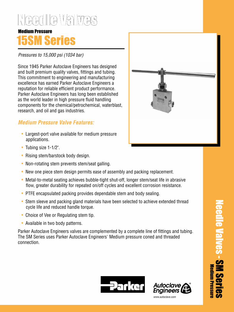
Since 1945 Parker Autoclave Engineers has designed and built premium quality valves, fittings and tubing. This commitment to engineering and manufacturing excellence has earned Parker Autoclave Engineers a reputation for reliable efficient product performance. Parker Autoclave Engineers has long been established as the world leader in high pressure fluid handling components for the chemical/petrochemical, waterblast, research, and oil and gas industries.
Medium Pressure Valve Features:
• Largest-port valve available for medium pressure applications.
• Tubing size 1-1/2".
• Rising stem/barstock body design.
• Non-rotating stem prevents stem/seat galling.
• New one piece stem design permits ease of assembly and packing replacement.
• Metal-to-metal seating achieves bubble-tight shut-off, longer stem/seat life in abrasive flow, greater durability for repeated on/off cycles and excellent corrosion resistance.
• PTFE encapsulated packing provides dependable stem and body sealing.
• Stem sleeve and packing gland materials have been selected to achieve extended thread cycle life and reduced handle torque.
• Choice of Vee or Regulating stem tip.
• Available in two body patterns.
Parker Autoclave Engineers valves are complemented by a complete line of fittings and tubing. The SM Series uses Parker Autoclave Engineers' Medium pressure coned and threaded connection.
Needle Valves
Pressures to 15,000 psi (1034 bar)
15SM SeriesMedium Pressure
Needle Valves - SM SeriesMedium
Pressure
www.autoclave.com

Needle Valves - 15SM SeriesPressures to 15,000 psi (1034 bar)
Tube Pressure Outside Rating Diameter Orifice psi (bar) Size Connection Size Rated @ Room Inches Type Inches (mm) Cv* Temperature** 1-1/2 SF1500CX .937 (23.80) 14 15,000 (1034)
Notes:
* CV values shown are for 2-way straight valve pattern. For 2-way angle patterns, increase CV value 50%. (Based on water)
** For complete temperature ratings see pressure/temperature rating guide in Technical Information section.
To ensure proper fit use Parker Autoclave tubing
Ordering ProcedureFor complete information on available stem types, optional connections and additional valve options, see Needle Valve Options section or contact your Sales Representative. 15SM Series valves are furnished complete with connection components, unless otherwise specified. Typical catalog number: 15SM24071
24-1-1/2” 07 - non-rotating Vee stem (on-off service)08 - non-rotating regulating stem (tapered tip for regulating and shutoff)
1 - two-way straight2 - two-way angle
For extreme temperature and other
options, see Valve Options.
XXOptions
1Body
Pattern
07Stem/Seat
Type
24Outside Diameter
Tube Size
15SMValveSeries
2 All general terms and conditions of sale, including limitations of our liability, apply to all products and services sold.
STAINLESS STEEL T-HANDLE
NON-ROTATINGSTEM
ADJUSTABLE PACKING BELOW THREADS
HIGH PRESSURE CONED AND THREADEDCONNECTIONS
METAL-TO-METAL SEATING
CHOICE OF VEE OR REGULATING STEM TIP
COLD WORKED TYPE 316 SS BODY IN TWOPATTERNS
ANTI-EXTRUSION BACK-UP RINGS
LOW FRICTION ALUMINUM BRONZE PACKING GLAND
NOT
AVAILABLE
Generalized Flow Coefficient Curves (Cv)
% of rated Cv
Num
ber
of tu
rns
open
10 20 30 40 50 60 70 80 90 100
7
6
5
4
3
2
1
0
Regulating Stem
Vee Stem

Valve Options Valve MaintenanceExtreme Temperatures Standard Parker Autoclave Engineers valves with PTFE packing may be operated from 0°F (-17.8°C) to 450°F (232°C). High temperature packing and/or extended stuffing box are available for service from -423°F (-252°C) to 1200°F (649°C) by adding the following suffixes to catalog order number.TG standard valve with PTFE glass packing to 600°F (316°C).GY standard valve with graphite braided yarn packing to 800°F (427°C). Note: Contact factory for pressure ratings using graphite yarn packing.HT extended stuffing box valve with graphite braided yarn packing to 1200°F (649°C).B standard valve with cryogenic trim materials and PTFE packing to -100°F (-73°C).LT extended stuffing box valve with PTFE packing and cryogenic trim materials to -423°F (-252°C).K anti-vibration collet and gland assembly
See needle valve options for stem and seat coating for erosive service.
Repair Kits: add “R” to the front of valve catalog number for proper repair kit. (Example: R15SM24071)
Valve Bodies: Valve bodies are available. Order using the eight (8) digit part number found on the valve drawing or contact your Sales Representative for information. Consult your Parker Autoclave Engineers representative for pricing on repair kits and valve bodies. Refer to the Tools, Installation, Operation and Mainte-nance section for proper maintenance procedures.
Note: Caution should be exercised in proper selection of medium pressure tub-ing based on actual operating conditions. Two tubing series available in some sizes: 15,000 psi (1034 bar) and 20,000 psi (1380 bar).
G - Packing gland mounting hole drill size * H Dimension is with stem in closed position. For prompt service, Parker G1 - Bracket mounting hole size All dimensions for reference only and subject to change. Autoclave Engineers stock select Panel mounting drill size: 0.75” all valves. products. Consult factory.
All general terms and conditions of sale, including limitations of our liability, apply to all products and services sold. 3
Dimensions - inches (mm)PipeSize
Fitting Pattern
StemType
H
N
F
G1
D
E
M M
A B
C
H N
F
G1
D1DE
M M
AB
C
2-Way Angle2-Way Straight
Figure 2Figure 1
2-Way Straight VEE 1-1/2 0.937 5.75 2.88 1.00 5.25 3.75 6.38 23.75 0.75 10.98 1.88 1.50 2.25 REG (38.10) (23.80) (146.05) (73.03) (25.40) (133.35) (95.25) (161.93) (603.25) (19.05) (278.79) (47.63) (38.10) (57.15)
See Fig. 1
15SM2407115SM24081
Block Thick-ness A B C D D1 E F G G1 H M N
2-Way Angle VEE 1-1/2 0.937 5.75 2.88 1.00 3.75 6.75 23.75 0.75 11.35 1.88 1.50 2.25 REG (38.10) (23.80) (146.05) (73.03) (25.40) (95.25) (171.45) (603.25) (19.05) (288.32) (47.63) (38.10) (57.15)
See Fig. 2
15SM2407215SM24082
OrificeDia.
Catalog Number
02-9225BE January2013© 2013 Parker Hannifin Corporation | Autoclave Engineers is a registered trademark of the Parker Hannifin Corporation
Parker Hannifin Manufacturing Ltd. Instrumentation Products Division, Europe Industrial Estate WhitemillWexford, Republic of IrelandPH: 353 53 914 1566FAX: 353 53 914 1582
Instrumentation Products DivisionAutoclave Engineers Operation8325 Hessinger DriveErie, Pennsylvania 16509-4679 USAPH: 814-860-5700 FAX: 814-860-5811www.autoclave.com
WARNING
FAILURE, IMPROPER SELECTION OR IMPROPER USE OF THE PRODUCTS AND/OR SYSTEMS DESCRIBED HEREIN OR RELATED ITEMS CAN CAUSE DEATH, PERSONAL INJURY AND PROPERTY DAMAGE.This document and other information from Parker Hannifin Corporation, its subsidiaries and authorized distributors provide product and/or system options for further investigation by users having technical expertise. It is important that you analyze all aspects of your application and review the information concerning the product or system in the current product catalog. Due to the variety of operating conditions and applications for these products or systems, the user, through its own analysis and testing, is solely responsible for making the final selection of the products and systems and assuring that all performance, safety and warning requirements of the application are met. The products described herein, including without limitation, product features, specifications, designs, availability and pricing, are subject to change by Parker Hannifin Corporation and its subsidiaries at any time without notice.
Offer of Sale
The items described in this document are available for sale by Parker Hannifin Corporation, its subsidiaries or its authorized distributors. Any sale contract entered by Parker will be governed by the provisions stated in Parker's standard terms and conditions of sale (copy available upon request).
ISO-9001 Certified
Caution! Do not mix or interchange parts or tubing with those of other manufacturers. Doing so is unsafe and will void warranty.
Caution! Parker Autoclave Engineers Valves, Fittings and Tools are not designed to work with common commercial instrument tubing and will only work with tubing built to Parker Autoclave Engineers AES Specifications. Failure to do so will void warranty.

Since 1945 Parker Autoclave Engineers has designed and built premium quality valves, fittings and tubing. This commitment to engineering and manufacturing excellence has earned Parker Autoclave Engineers a reputation for reliable efficient product performance. Parker Autoclave Engineers has long been established as the world leader in high pressure fluid handling components for the chemical/petrochemical, waterblast, research, and oil and gas industries.
Medium Pressure Valve Features:
• Largest-port valves available for medium pressure applications.
• Tubing sizes available from 1/4” to 1”.
• Rising stem/barstock body design.
• Non-rotating stem prevents stem/seat galling.
• New one piece stem design permits ease of assembly and packing replacement.
• Metal-to-metal seating achieves bubble-tight shut-off, longer stem/seat life in abrasive flow, greater durability for repeated on/off cycles and excellent corrosion resistance.
• PTFE encapsulated packing provides dependable stem and body sealing.
• Stem sleeve and packing gland materials have been selected to achieve extended thread cycle life and reduced handle torque.
• Choice of Vee or Regulating stem tip.
• Available in five body patterns.
Parker Autoclave Engineers valves are complemented by a complete line of fittings, tubing, check valves and line filters. The SM Series uses Parker Autoclave Engineers’ Medium pressure connection. The coned-and-threaded connection features orifice sizes to match the high flow characteristics of this series.
Note: SM Series replaces 20SC Series.
Needle Valves
Pressures to 20,000 psi (1379 bar)
SM SeriesMedium Pressure
Needle Valves - SM SeriesMedium
Pressure
www.autoclave.com
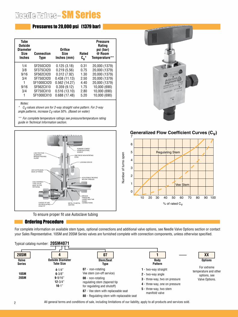
Needle Valves - SM SeriesPressures to 20,000 psi (1379 bar)
Tube Pressure Outside Rating Diameter Orifice psi (bar) Size Connection Size Rated @ Room Inches Type Inches (mm) Cv* Temperature** 1/4 SF250CX20 0.125 (3.18) 0.31 20,000 (1379) 3/8 SF375CX20 0.219 (5.56) 0.75 20,000 (1379) 9/16 SF562CX20 0.312 (7.92) 1.30 20,000 (1379) 3/4 SF750CX20 0.438 (11.13) 2.50 20,000 (1379) 1 SF1000CX20 0.562 (14.27) 4.40 20,000 (1379) 9/16 SF562CX10 0.359 (9.12) 1.75 10,000 (690) 3/4 SF750CX10 0.516 (13.10) 2.80 10,000 (690) 1 SF1000CX10 0.688 (17.48) 5.20 10,000 (690) Notes:
* CV values shown are for 2-way straight valve pattern. For 2-way angle patterns, increase CV value 50%. (Based on water)
** For complete temperature ratings see pressure/temperature rating guide in Technical Information section.
To ensure proper fit use Autoclave tubing
Ordering ProcedureFor complete information on available stem types, optional connections and additional valve options, see Needle Valve Options section or contact your Sales Representative. 10SM and 20SM Series valves are furnished complete with connection components, unless otherwise specified. Typical catalog number: 20SM4071
LOCKING DEVICE
ADJUSTABLE PACKING BELOW THREADS
MEDIUM PRESSURE CONED-AND-THREADED CONNECTIONSMETAL-TO-METAL
SEATING
CHOICE OF VEE OR REGULATING STEM TIP
COLD WORKED TYPE 316 SS BODY IN FIVE PATTERNS
ANTI-EXTRUSION BACK-UP RINGS
LOW FRICTION ALUMINUM BRONZE PACKING GLAND
ONE PIECE NON-ROTATINGSTEM
POWDER COATEDSTAINLESS STEELHANDLE
Generalized Flow Coefficient Curves (Cv)
% of rated Cv
Num
ber
of tu
rns
open
10 20 30 40 50 60 70 80 90 100
7
6
5
4
3
2
1
0
Regulating Stem
Vee Stem
4-1/4”6-3/8”9-9/16” 12-3/4”16-1”
07 - non-rotating Vee stem (on-off service)08 - non-rotating regulating stem (tapered tip for regulating and shutoff)87 - Vee stem with replaceable seat88 - Regulating stem with replaceable seat
1 - two-way straight2 - two-way angle3 - three-way, two on pressure4 - three-way, one on pressure5 - three-way, two stem manifold valve
For extreme temperature and other
options, see Valve Options.
XXOptions
1Body
Pattern
07Stem/Seat
Type
4Outside Diameter
Tube Size
20SMValveSeries
10SM20SM
2 All general terms and conditions of sale, including limitations of our liability, apply to all products and services sold.
Valve Options Valve MaintenanceExtreme Temperatures Standard Parker Autoclave Engineers valves with PTFE packing may be operated from 0°F (-17.8°C) to 450°F (232°C). High temperature packing and/or extended stuffing box are available for service from -423°F (-252°C) to 1200°F (649°C) by adding the following suffixes to catalog order number.TG standard valve with PTFE glass packing to 600°F (316°C).GY standard valve with graphite braided yarn packing to 800°F (427°C). Note: 3/4” rated 8000 psi (552 bar) and 1” rated 6000 psi (412 bar) maxi-mum with graphite yarn packing.HT extended stuffing box valve with graphite braided yarn packing to 1200°F (649°C).B standard valve with cryogenic trim materials and PTFE packing to -100°F (-73°C).LT extended stuffing box valve with PTFE packing and cryogenic trim materials to -423°F (-252°C).K anti-vibration collet and gland assembly
See needle valve options for stem and seat coating for erosive service.
Repair Kits: add “R” to the front of valve catalog number for proper repair kit. (Example: R20SM4071)
Valve Bodies: Valve bodies are available. Order using the eight (8) digit part number found on the valve drawing or contact your Sales Representative for information. Consult your Parker Autoclave Engineersrepresentative for pricing on repair kits and valve bodies. Refer to the Tools, Installation, Operation and Maintenance section for proper maintenance procedures.
Note: Caution should be exercised in proper selection of medium pressure tubing based on actual operating conditions. Two tubing series available in some sizes: 15,000 psi (1034 bar) and 20,000 psi (1380 bar).
Block Catalog Stem Diameter Orifice Thick- Valve Number Type Tube Diameter A B C D D1 E F G G1 H* M N ness Pattern
Dimensions - inches (mm)
2-Way Straight 20SM4071 VEE 20SM4081 REG 20SM6071 VEE 20SM6081 REG 20SM9071 VEE 20SM9081 REG 20SM12071 VEE 20SM12081 REG 20SM16071 VEE 20SM16081 REG 10SM9071 VEE 10SM9081 REG 10SM12071 VEE 10SM12081 REG 10SM16071 VEE 10SM16081 REG
1/4 0.125 2.00 1.00 0.38 1.62 1.19 2.00 3.00 0.75 0.22 4.69 0.62 0.38 0.75 (6.35) (3.18) (50.80) (25.40) (9.65) (41.15) (30.23) (50.80) (76.20) (19.05) (5.59) (119.13) (15.75) (9.65) (19.05) 3/8 0.219 2.00 1.00 0.47 1.62 1.19 2.00 3.00 0.75 0.22 4.63 0.62 0.38 0.75 (9.53) (5.56) (50.80) (25.40) (11.94) (41.15) (30.23) (50.80) (76.20) (19.05) (5.59) (117.48) (15.75) (9.65) (19.05) 9/16 0.312 2.50 1.25 0.53 2.38 1.75 2.88 4.00 1.00 0.34 5.93 0.69 0.50 1.00 (14.29) (7.92) (63.50) (31.75) (13.46) (60.45) (44.45) (73.15) (101.60) (25.40) (8.64) (150.86) (17.53) (12.70) (25.40) 3/4 0.438 3.00 1.50 0.62 3.00 2.25 3.75 10.25 1.12 0.44 7.00 0.88 0.63 1.38 (19.05) (11.13) (76.20) (38.10) (15.75) (76.20) (57.15) (95.25) (260.35) (28.45) (11.18) (177.80) (22.35) (16.00) (35.05) 1 0.562 4.12 2.06 0.63 3.75 2.81 4.63 10.25 1.62 0.56 9.00 1.25 1.13 1.75 (25.40) (14.27) (104.65) (52.32) (16.00) (95.25) (71.37) (117.60) (260.35) (41.15) (14.22) (228.84) (31.75) (28.70) (44.4 5) 9/16 0.359 2.50 1.25 0.53 2.38 1.75 2.88 4.00 1.00 0.34 5.93 0.69 0.50 1.00 (14.29) (9.12) (63.50) (31.75) (13.46) (60.45) (44.45) (73.15) (101.60) (25.40) (8.64) (150.86) (17.53) (12.70) (25.40) 3/4 0.516 3.00 1.50 0.62 3.00 2.25 3.75 10.25 1.12 0.44 7.00 0.88 0.63 1.38 (19.05) (13.11) (76.20) (38.10) (15.75) (76.20) (57.15) (95.25) (260.35) (28.45) (11.18) (177.80) (22.35) (16.00) (35.05) 1 0.688 4.12 2.06 0.63 3.75 2.81 4.63 10.25 1.62 0.56 9.00 1.25 1.13 1.75 (25.40) (17.48) (104.65) (52.32) (16.00) (95.25) (71.37) (117.60) (260.35) (41.15) (14.22) (228.84) (31.75) (28.70) (44.45)
Outside
2-Way Straight
Figure 1
See Figure 1
H N
F
G1
G
D1DE
M M
AB
C
All general terms and conditions of sale, including limitations of our liability, apply to all products and services sold. 3
G - Packing gland mounting hole drill size * H Dimension is with stem in closed position. G1 - Bracket mounting hole size All dimensions for reference only and subject to change. Panel mounting drill size: 0.22” all valves.
For prompt service, Parker Autoclave Engineers stock select products. Consult factory.

Block Catalog Stem Diameter Orifice Thick- Valve Number Type Tube Diameter A B C D D1 E F G G1 H* M N ness Pattern
Dimensions - inches (mm)
2-Way Angle 20SM4072 VEE 20SM4082 REG 20SM6072 VEE 20SM6082 REG 20SM9072 VEE 20SM9082 REG 20SM12072 VEE 20SM12082 REG 20SM16072 VEE 20SM16082 REG 10SM9072 VEE 10SM9082 REG 10SM12072 VEE 10SM12082 REG 10SM16072 VEE 10SM16082 REG
1/4 0.125 2.00 1.00 0.38 1.19 2.44 3.00 0.75 0.22 4.81 0.62 0.38 0.75 (6.35) (3.18) (50.80) (25.40) (9.65) (30.23) (61.90) (76.20) (19.05) (5.59) (122.25) (15.75) (9.65) (19.05) 3/8 0.219 2.00 1.00 0.47 1.19 2.44 3.00 0.75 0.22 4.81 0.62 0.38 0.75 (9.53) (5.56) (50.80) (25.40) (11.94) (30.23) (61.90) (76.20) (19.05) (5.59) (122.25) (15.75) (9.65) (19.05) 9/16 0.312 2.50 1.25 0.53 1.75 3.38 4.00 1.00 0.34 6.43 0.69 0.50 1.00 (14.29) (7.92) (63.50) (31.75) (13.46) (44.45) (85.85) (101.60) (25.40) (8.64) (163.56) (17.53) (12.70) (25.40) 3/4 0.438 3.00 1.50 0.62 2.25 4.25 10.25 1.12 0.44 7.50 0.88 0.63 1.38 (19.05) (11.13) (76.20) (38.10) (15.75) (57.15) (107.95) (260.35) (28.45) (11.18) (190.50) (22.35) (16.00) (35.05) 1 0.562 4.12 2.06 0.63 2.81 5.12 10.25 1.62 0.56 9.00 1.25 1.13 1.75 (25.40) (14.27) (104.65) (52.32) (16.00) (71.37) (130.05) (260.35) (41.15) (14.22) (228.84) (31.75) (28.70) (44.4 5) 9/16 0.359 2.50 1.25 0.53 1.75 3.38 4.00 1.00 0.34 6.43 0.69 0.50 1.00 (14.29) (9.12) (63.50) (31.75) (13.46) (44.45) (85.85) (101.60) (25.40) (8.64) (163.56) (17.53) (12.70) (25.40) 3/4 0.516 3.00 1.50 0.62 2.25 4.25 10.25 1.12 0.44 7.50 0.88 0.63 1.38 (19.03) (13.11) (76.20) (38.10) (15.75) (57.15) (107.95) (260.35) (28.45) (11.18) (190.50) (22.35) (16.00) (35.05) 1 0.688 4.12 2.06 0.63 2.81 5.12 10.25 1.62 0.56 9.00 1.25 1.13 1.75 (25.40) (17.48) (104.65) (52.32) (16.00) (71.37) (130.05) (260.35) (41.15) (14.22) (228.84) (31.75) (28.70) (44.45)
Outside
See Figure 2
3-Way / 2 on Pressure 20SM4073 VEE 20SM4083 REG 20SM6073 VEE 20SM6083 REG 20SM9073 VEE 20SM9083 REG 20SM12073 VEE 20SM12083 REG 20SM16073 VEE 20SM16083 REG 10SM9073 VEE 10SM9083 REG 10SM12073 VEE 10SM12083 REG 10SM16073 VEE 10SM16083 REG
1/4 0.125 2.00 1.00 0.38 1.63 1.19 2.63 3.00 0.75 0.22 5.00 0.62 0.38 0.75 (6.35) (3.18) (50.80) (25.40) (9.65) (41.28) (30.23) (66.68) (76.20) (19.05) (5.59) (127.00) (15.75) (9.65) (19.05) 3/8 0.219 2.00 1.00 0.47 1.63 1.19 2.63 3.00 0.75 0.22 5.00 0.62 0.38 0.75 (9.53) (5.56) (50.80) (25.40) (11.94) (41.28) (30.23) (66.68) (76.20) (19.05) (5.59) (127.00) (15.75) (9.65) (19.05) 9/16 0.312 2.50 1.25 0.53 2.38 1.75 3.63 4.00 1.00 0.34 6.51 0.69 0.50 1.00 (14.29) (7.92) (63.50) (31.75) (13.46) (60.45) (44.45) (92.08) (101.60) (25.40) (8.64) (165.59) (17.53) (12.70) (25.40) 3/4 0.438 3.00 1.50 0.62 3.00 2.25 4.63 10.25 1.12 0.44 7.88 0.88 0.63 1.38 (19.05) (11.13) (76.20) (38.10) (15.75) (76.20) (57.15) (117.48) (260.35) (28.45) (11.18) (200.03) (22.35) (16.00) (35.05) 1 0.562 4.12 2.06 0.63 3.75 2.81 5.88 10.25 1.62 0.56 9.75 1.25 1.13 1.75 (25.40) (14.27) (104.65) (52.32) (16.00) (95.25) (71.37) (149.35) (260.35) (41.15) (14.22) (247.89) (31.75) (28.70) (44.4 5) 9/16 0.359 2.50 1.25 0.53 2.38 1.75 3.63 4.00 1.00 0.34 6.52 0.69 0.50 1.00 (14.29) (9.12) (63.50) (31.75) (13.46) (60.45) (44.45) (92.08) (101.60) (25.40) (8.64) (165.59) (17.53) (12.70) (25.40) 3/4 0.516 3.00 1.50 0.62 3.00 2.25 4.63 10.25 1.12 0.44 7.88 0.88 0.63 1.38 (19.03) (13.11) (76.20) (38.10) (15.75) (76.20) (57.15) (117.48) (260.35) (28.45) (11.18) (200.03) (22.35) (16.00) (35.05) 1 0.688 4.12 2.06 0.63 3.75 2.81 5.88 10.25 1.62 0.56 9.75 1.25 1.13 1.75 (25.40) (17.48) (104.65) (52.32) (16.00) (95.25) (71.37) (149.35) (260.35) (41.15) (14.22) (247.89) (31.75) (28.70) (44.45)
See Figure 3
2-Way Angle
Figure 2
3-Way / 2 on Pressure
Figure 3
H
F
G1G
D
E
A
M
B
M
N
C
H
F
G1G
D1
E
A
C
B
M M
N
D
4 All general terms and conditions of sale, including limitations of our liability, apply to all products and services sold.
G - Packing gland mounting hole drill size * H Dimension is with stem in closed position. G1 - Bracket mounting hole size All dimensions for reference only and subject to change. Panel mounting drill size: 0.22” all valves.
For prompt service, Parker Autoclave Engineers stock select products. Consult factory.
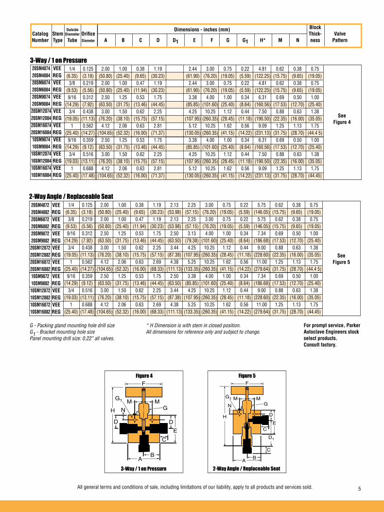
2-Way Angle / Replaceable Seat
3-Way / 1 on Pressure
Block Catalog Stem Diameter Orifice Thick- Valve Number Type Tube Diameter A B C D D1 E F G G1 H* M N ness Pattern
Dimensions - inches (mm)
20SM4074 VEE 20SM4084 REG 20SM6074 VEE 20SM6084 REG 20SM9074 VEE 20SM9084 REG 20SM12074 VEE 20SM12084 REG 20SM16074 VEE 20SM16084 REG 10SM9074 VEE 10SM9084 REG 10SM12074 VEE 10SM12084 REG 10SM16074 VEE 10SM16084 REG
1/4 0.125 2.00 1.00 0.38 1.19 2.44 3.00 0.75 0.22 4.81 0.62 0.38 0.75 (6.35) (3.18) (50.80) (25.40) (9.65) (30.23) (61.90) (76.20) (19.05) (5.59) (122.25) (15.75) (9.65) (19.05) 3/8 0.219 2.00 1.00 0.47 1.19 2.44 3.00 0.75 0.22 4.81 0.62 0.38 0.75 (9.53) (5.56) (50.80) (25.40) (11.94) (30.23) (61.90) (76.20) (19.05) (5.59) (122.25) (15.75) (9.65) (19.05) 9/16 0.312 2.50 1.25 0.53 1.75 3.38 4.00 1.00 0.34 6.31 0.69 0.50 1.00 (14.29) (7.92) (63.50) (31.75) (13.46) (44.45) (85.85) (101.60) (25.40) (8.64) (160.56) (17.53) (12.70) (25.40) 3/4 0.438 3.00 1.50 0.62 2.25 4.25 10.25 1.12 0.44 7.50 0.88 0.63 1.38 (19.05) (11.13) (76.20) (38.10) (15.75) (57.15) (107.95) (260.35) (28.45) (11.18) (190.50) (22.35) (16.00) (35.05) 1 0.562 4.12 2.06 0.63 2.81 5.12 10.25 1.62 0.56 9.09 1.25 1.13 1.75 (25.40) (14.27) (104.65) (52.32) (16.00) (71.37) (130.05) (260.35) (41.15) (14.22) (231.13) (31.75) (28.70) (44.4 5) 9/16 0.359 2.50 1.25 0.53 1.75 3.38 4.00 1.00 0.34 6.31 0.69 0.50 1.00 (14.29) (9.12) (63.50) (31.75) (13.46) (44.45) (85.85) (101.60) (25.40) (8.64) (160.56) (17.53) (12.70) (25.40) 3/4 0.516 3.00 1.50 0.62 2.25 4.25 10.25 1.12 0.44 7.50 0.88 0.63 1.38 (19.03) (13.11) (76.20) (38.10) (15.75) (57.15) (107.95) (260.35) (28.45) (11.18) (190.50) (22.35) (16.00) (35.05) 1 0.688 4.12 2.06 0.63 2.81 5.12 10.25 1.62 0.56 9.09 1.25 1.13 1.75 (25.40) (17.48) (104.65) (52.32) (16.00) (71.37) (130.05) (260.35) (41.15) (14.22) (231.13) (31.75) (28.70) (44.45)
Outside
See Figure 4
3-Way / 1 on Pressure
Figure 4
2-Way Angle / Replaceable Seat
Figure 5
20SM4872 VEE 20SM4882 REG 20SM6872 VEE 20SM6882 REG 20SM9872 VEE 20SM9882 REG 20SM12872 VEE 20SM12882 REG 20SM16872 VEE 20SM16882 REG 10SM9872 VEE 10SM9882 REG 10SM12872 VEE 10SM12882 REG 10SM16872 VEE 10SM16882 REG
1/4 0.125 2.00 1.00 0.38 1.19 2.13 2.25 3.00 0.75 0.22 5.75 0.62 0.38 0.75 (6.35) (3.18) (50.80) (25.40) (9.65) (30.23) (53.98) (57.15) (76.20) (19.05) (5.59) (146.05) (15.75) (9.65) (19.05) 3/8 0.219 2.00 1.00 0.47 1.19 2.13 2.25 3.00 0.75 0.22 5.75 0.62 0.38 0.75 (9.53) (5.56) (50.80) (25.40) (11.94) (30.23) (53.98) (57.15) (76.20) (19.05) (5.59) (146.05) (15.75) (9.65) (19.05) 9/16 0.312 2.50 1.25 0.53 1.75 2.50 3.13 4.00 1.00 0.34 7.34 0.69 0.50 1.00 (14.29) (7.92) (63.50) (31.75) (13.46) (44.45) (63.50) (79.38) (101.60) (25.40) (8.64) (186.68) (17.53) (12.70) (25.40) 3/4 0.438 3.00 1.50 0.62 2.25 3.44 4.25 10.25 1.12 0.44 9.00 0.88 0.63 1.38 (19.05) (11.13) (76.20) (38.10) (15.75) (57.15) (87.38) (107.95) (260.35) (28.45) (11.18) (228.60) (22.35) (16.00) (35.05) 1 0.562 4.12 2.06 0.63 2.69 4.38 5.25 10.25 1.62 0.56 11.00 1.25 1.13 1.75 (25.40) (14.27) (104.65) (52.32) (16.00) (68.33) (111.13) (133.35) (260.35) (41.15) (14.22) (279.64) (31.75) (28.70) (44.4 5) 9/16 0.359 2.50 1.25 0.53 1.75 2.50 3.38 4.00 1.00 0.34 7.34 0.69 0.50 1.00 (14.29) (9.12) (63.50) (31.75) (13.46) (44.45) (63.50) (85.85) (101.60) (25.40) (8.64) (186.68) (17.53) (12.70) (25.40) 3/4 0.516 3.00 1.50 0.62 2.25 3.44 4.25 10.25 1.12 0.44 9.00 0.88 0.63 1.38 (19.03) (13.11) (76.20) (38.10) (15.75) (57.15) (87.38) (107.95) (260.35) (28.45) (11.18) (228.60) (22.35) (16.00) (35.05) 1 0.688 4.12 2.06 0.63 2.69 4.38 5.25 10.25 1.62 0.56 11.00 1.25 1.13 1.75 (25.40) (17.48) (104.65) (52.32) (16.00) (68.33) (111.13) (133.35) (260.35) (41.15) (14.22) (279.64) (31.75) (28.70) (44.45)
See Figure 5
H N
M M
F
G1
G
DD
E
C
BA
H
N
M M
F
G1
G
D
EC
BA
C
D1
All general terms and conditions of sale, including limitations of our liability, apply to all products and services sold. 5
G - Packing gland mounting hole drill size * H Dimension is with stem in closed position. G1 - Bracket mounting hole size All dimensions for reference only and subject to change. Panel mounting drill size: 0.22” all valves.
For prompt service, Parker Autoclave Engineers stock select products. Consult factory.
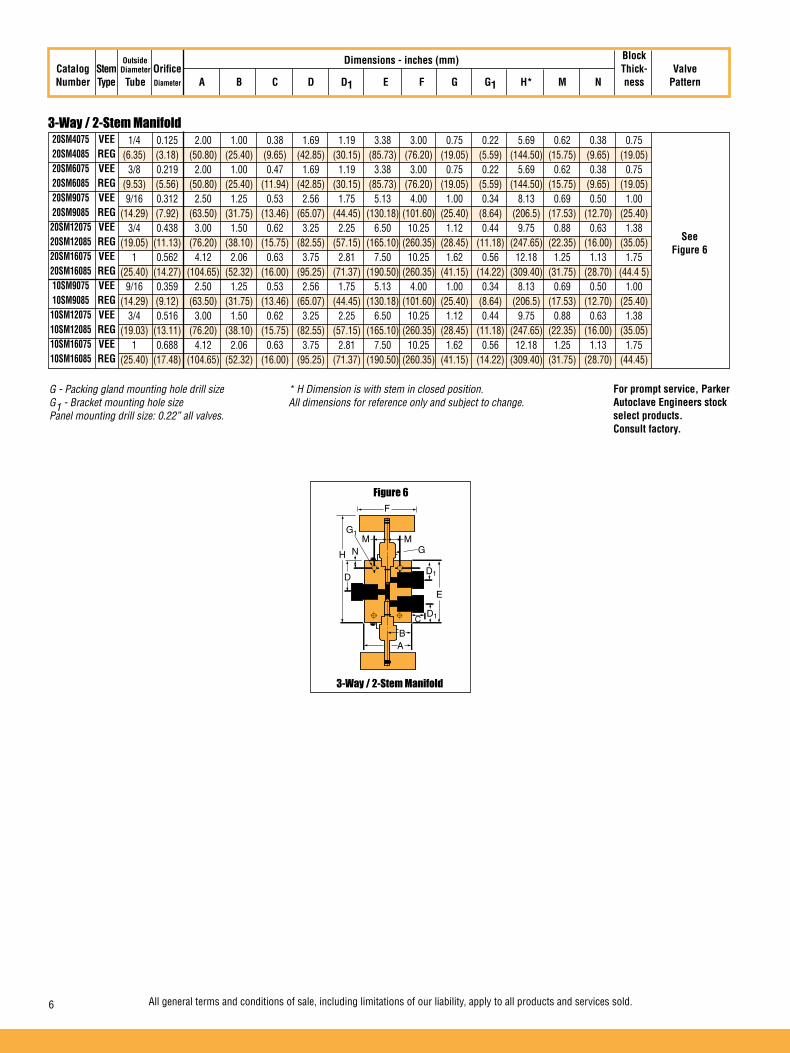
3-Way / 2-Stem Manifold
Block Catalog Stem Diameter Orifice Thick- Valve Number Type Tube Diameter A B C D D1 E F G G1 H* M N ness Pattern
Dimensions - inches (mm)Outside
3-Way / 2-Stem Manifold
Figure 6
20SM4075 VEE 20SM4085 REG 20SM6075 VEE 20SM6085 REG 20SM9075 VEE 20SM9085 REG 20SM12075 VEE 20SM12085 REG 20SM16075 VEE 20SM16085 REG 10SM9075 VEE 10SM9085 REG 10SM12075 VEE 10SM12085 REG 10SM16075 VEE 10SM16085 REG
1/4 0.125 2.00 1.00 0.38 1.69 1.19 3.38 3.00 0.75 0.22 5.69 0.62 0.38 0.75 (6.35) (3.18) (50.80) (25.40) (9.65) (42.85) (30.15) (85.73) (76.20) (19.05) (5.59) (144.50) (15.75) (9.65) (19.05) 3/8 0.219 2.00 1.00 0.47 1.69 1.19 3.38 3.00 0.75 0.22 5.69 0.62 0.38 0.75 (9.53) (5.56) (50.80) (25.40) (11.94) (42.85) (30.15) (85.73) (76.20) (19.05) (5.59) (144.50) (15.75) (9.65) (19.05) 9/16 0.312 2.50 1.25 0.53 2.56 1.75 5.13 4.00 1.00 0.34 8.13 0.69 0.50 1.00 (14.29) (7.92) (63.50) (31.75) (13.46) (65.07) (44.45) (130.18) (101.60) (25.40) (8.64) (206.5) (17.53) (12.70) (25.40) 3/4 0.438 3.00 1.50 0.62 3.25 2.25 6.50 10.25 1.12 0.44 9.75 0.88 0.63 1.38 (19.05) (11.13) (76.20) (38.10) (15.75) (82.55) (57.15) (165.10) (260.35) (28.45) (11.18) (247.65) (22.35) (16.00) (35.05) 1 0.562 4.12 2.06 0.63 3.75 2.81 7.50 10.25 1.62 0.56 12.18 1.25 1.13 1.75 (25.40) (14.27) (104.65) (52.32) (16.00) (95.25) (71.37) (190.50) (260.35) (41.15) (14.22) (309.40) (31.75) (28.70) (44.4 5) 9/16 0.359 2.50 1.25 0.53 2.56 1.75 5.13 4.00 1.00 0.34 8.13 0.69 0.50 1.00 (14.29) (9.12) (63.50) (31.75) (13.46) (65.07) (44.45) (130.18) (101.60) (25.40) (8.64) (206.5) (17.53) (12.70) (25.40) 3/4 0.516 3.00 1.50 0.62 3.25 2.25 6.50 10.25 1.12 0.44 9.75 0.88 0.63 1.38 (19.03) (13.11) (76.20) (38.10) (15.75) (82.55) (57.15) (165.10) (260.35) (28.45) (11.18) (247.65) (22.35) (16.00) (35.05) 1 0.688 4.12 2.06 0.63 3.75 2.81 7.50 10.25 1.62 0.56 12.18 1.25 1.13 1.75 (25.40) (17.48) (104.65) (52.32) (16.00) (95.25) (71.37) (190.50) (260.35) (41.15) (14.22) (309.40) (31.75) (28.70) (44.45)
See Figure 6
6 All general terms and conditions of sale, including limitations of our liability, apply to all products and services sold.
H NM M
F
G1
G
D1
E
C
BA
D1
D
G - Packing gland mounting hole drill size * H Dimension is with stem in closed position. G1 - Bracket mounting hole size All dimensions for reference only and subject to change. Panel mounting drill size: 0.22” all valves.
For prompt service, Parker Autoclave Engineers stock select products. Consult factory.

All general terms and conditions of sale, including limitations of our liability, apply to all products and services sold. 7
02-0112SE January2013© 2013 Parker Hannifin Corporation | Autoclave Engineers is a registered trademark of the Parker Hannifin Corporation
Parker Hannifin Manufacturing Ltd. Instrumentation Products Division, Europe Industrial Estate WhitemillWexford, Republic of IrelandPH: 353 53 914 1566FAX: 353 53 914 1582
Instrumentation Products DivisionAutoclave Engineers Operation8325 Hessinger DriveErie, Pennsylvania 16509-4679 USAPH: 814-860-5700 FAX: 814-860-5811www.autoclave.com
WARNINGFAILURE, IMPROPER SELECTION OR IMPROPER USE OF THE PRODUCTS AND/OR SYSTEMS DESCRIBED HEREIN OR RELATED ITEMS CAN CAUSE DEATH, PERSONAL INJURY AND PROPERTY DAMAGE.This document and other information from Parker Hannifin Corporation, its subsidiaries and authorized distributors provide product and/or system options for further investiga-tion by users having technical expertise. It is important that you analyze all aspects of your application and review the information concerning the product or system in the current product catalog. Due to the variety of operating conditions and applications for these products or systems, the user, through its own analysis and testing, is solely responsible for making the final selection of the products and systems and assuring that all performance, safety and warning requirements of the application are met. The products described herein, including without limitation, product features, specifications, designs, availability and pricing, are subject to change by Parker Hannifin Corporation and its subsidiaries at any time without notice.
Offer of SaleThe items described in this document are available for sale by Parker Hannifin Corporation, its subsidiaries or its authorized distributors. Any sale contract entered by Parker will begoverned by the provisions stated in Parker's standard terms and conditions of sale (copy available upon request).
ISO-9001 Certified
Caution! Do not mix or interchange parts or tubing with those of other manufacturers. Doing so is unsafe and will void warranty.
Caution! Parker Autoclave Engineers Valves, Fittings and Tools are not designed to work with common commercial instrument tubing and will only work with tubing built to Parker Autoclave Engineers AES Specifications. Failure to do so will void warranty.
1
Needle Valves
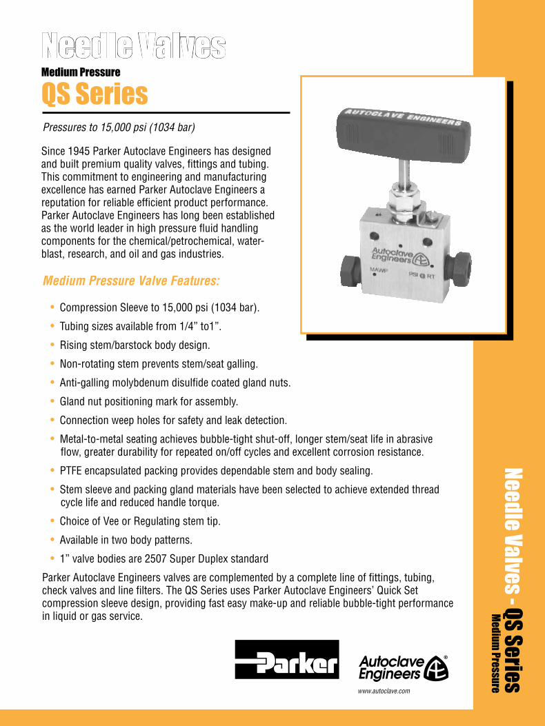
Pressures to 15,000 psi (1034 bar)
QS Series
Medium Pressure Valve Features:
• Compression Sleeve to 15,000 psi (1034 bar).
• Tubing sizes available from 1/4” to1”.
• Rising stem/barstock body design.
• Non-rotating stem prevents stem/seat galling.
• Anti-galling molybdenum disulfide coated gland nuts.
• Gland nut positioning mark for assembly.
• Connection weep holes for safety and leak detection.
• Metal-to-metal seating achieves bubble-tight shut-off, longer stem/seat life in abrasive flow, greater durability for repeated on/off cycles and excellent corrosion resistance.
• PTFE encapsulated packing provides dependable stem and body sealing.
• Stem sleeve and packing gland materials have been selected to achieve extended thread cycle life and reduced handle torque.
• Choice of Vee or Regulating stem tip.
• Available in two body patterns.
• 1” valve bodies are 2507 Super Duplex standard
Parker Autoclave Engineers valves are complemented by a complete line of fittings, tubing, check valves and line filters. The QS Series uses Parker Autoclave Engineers’ Quick Set compression sleeve design, providing fast easy make-up and reliable bubble-tight performance in liquid or gas service.
Needle Valves - QS SeriesMedium
Pressure
Medium Pressure
Since 1945 Parker Autoclave Engineers has designed and built premium quality valves, fittings and tubing. This commitment to engineering and manufacturing excellence has earned Parker Autoclave Engineers a reputation for reliable efficient product performance. Parker Autoclave Engineers has long been established as the world leader in high pressure fluid handling components for the chemical/petrochemical, water-blast, research, and oil and gas industries.
www.autoclave.com

2
Pressures to 15,000 psi (1034 bar)
Tube Pressure Outside Rating Diameter Orifice psi (bar) Size Connection Size Rated @ Room Inches Type Inches (mm) Cv* Temperature** 1/4 QS 250 0.125 (3.18) 0.31 15,000 (1034) 3/8 QS 375 0.219 (5.56) 0.75 15,000 (1034) 9/16 QS 562 0.359 (9.12) 2.80 15,000 (1034) 3/4 QS 750 0.516 (13.10) 5.20 15,000 (1034) 1 QS 1000 0.688 (17.48) 5.20 15,000 (1034) Notes:
* CV values shown are for 2-way straight valve pattern. For 2-way angle patterns, increase CV value 50%. (Based on water)
** For complete temperature ratings see pressure/temperature rating guide in Technical Information section.
Needle Valves - QS Series
To ensure proper fit use Parker Autoclave Engineers tubing
Ordering ProcedureFor complete information on available stem types, optional connections and additional valve options, see Needle Valve Options section or contact your Sales Representative. QS Series valves are furnished complete with connection components, unless otherwise specified.
Typical catalog number: 15QS4071
4-1/4”6-3/8”9-9/16” 12-3/4”16-1”
07 - non-rotating Vee stem (on-off service)08 - non-rotating regulating stem (tapered tip for regulating and shutoff)87 - Vee stem with replaceable seat88 - Regulating stem with replaceable seat
1 - two-way straight2 - two-way angle3 - three-way, two on pressure4 - three-way, one on pressure5 - three-way, two stem manifold valve
TG - PTFE Glass PlatingGY - Graphite Yarn Packing
See valve options for ratings
XXOptions
1Body
Pattern
07Stem/Seat
Type
4Outside Diameter
Tube Size
15QSValveSeries
15QS
Generalized Flow Coefficient Curves (Cv)
% of rated Cv
Num
ber
of tu
rns
open
10 20 30 40 50 60 70 80 90 100
7
6
5
4
3
2
1
0
Regulating Stem
Vee Stem
LOCKING DEVICE
ADJUSTABLE PACKING BELOW THREADS
METAL-TO-METAL SEATING
CHOICE OF VEE OR REGULATING STEM TIP
COLD WORKED TYPE 316 SS BODY IN FIVE PATTERNS(See Note)
ANTI-EXTRUSION BACK-UP RINGS
LOW FRICTION ALUMINUM BRONZE PACKING GLAND
ONE PIECE NON-ROTATINGSTEM
POWDER COATEDSTAINLESS STEELHANDLE
MEDIUM PRESSURE COMPRESSION SLEEVE CONNECTIONS
(Note: 1” valves are 2507 Super Duplex)

3
2-Way Straight
2-Way Angle
Block Catalog Stem Diameter Orifice Thick- Valve Number Type Tube Diameter A B C D D1 E F G G1 H* M N ness Pattern
Valve MaintenanceValve OptionsExtreme Temperatures Standard Parker Autoclave Engineers valves with PTFE packing may be operated to 450°F (232°C). High temperature packing and/or extended stuffing box are available for service from -100°F (-73°C) to 650°F (343°C) by adding the following suffixes to catalog order number.†TG standard valve with PTFE glass packing to 600°F (316°C).GY standard valve with graphite braided yarn packing to 650°F (343°C).B standard valve with cryogenic trim materials and PTFE packing to -100°F (-73°C).
†Parker Autoclave Engineers does not recommend compression sleeve connections below -100°F (-73°C) or above 650°F (343°C). For additional valve options, contact your Sales Representative.
Repair Kits: add “R” to the front of valve catalog number for proper repair kit. (Example: R15QS4071)
Valve Bodies: Valve bodies are available. Order using the eight (8) digit part number found on the valve drawing or contact your Sales Representative for information. Consult your Parker Autoclave Engineers representative for pricing on repair kits and valve bodies.
G - Packing gland mounting hole drill size * H Dimension is with stem in closed position. For prompt service, Parker Autoclave Engineers stocks G1 - Bracket mounting hole size **1/8" straight and 3-Way/2 on pressure valves have offset select products. Consult factory. Panel mounting drill size: 0.22” all valves. tube connections All dimensions for reference only and subject to change.
Dimensions - inches (mm)
15QS4071 VEE 15QS4081 REG 15QS6071 VEE 15QS6081 REG 15QS9071 VEE 15QS9081 REG 15QS12071 VEE 15QS12081 REG 15QS16071 VEE 15QS16081 REG
1/4 0.125 2.00 1.00 0.38 1.62 1.19 2.00 3.00 0.75 0.22 4.69 0.62 0.38 0.75 (6.35) (3.18) (50.80) (25.40) (9.53) (41.15) (30.23) (50.80) (76.20) (19.05) (5.59) (119.13) (15.75) (9.65) (19.05) 3/8 0.219 2.00 1.00 0.47 1.62 1.19 2.00 3.00 0.75 0.22 4.63 0.62 0.38 0.81 (9.53) (5.56) (50.80) (25.40) (11.94) (41.15) (30.23) (50.80) (76.20) (19.05) (5.59) (117.60) (15.75) (9.65) (20.57) 9/16 0.359 3.00 1.50 0.53 2.38 1.75 3.00 4.00 1.00 0.34 6.05 0.69 0.50 1.25 (14.29) (9.12) (76.20) (38.10) (13.46) (60.45) (44.45) (76.20) (101.60) (25.40) (8.64) (153.67) (17.53) (12.70) (31.75) 3/4 0.516 4.12 2.06 0.62 3.00 2.25 3.88 10.25 1.12 0.44 7.13 0.88 0.63 1.50 (19.05) (13.11) (104.65) (52.32) (15.75) (76.20) (57.15) (98.43) (260.35) (28.45) (11.18) (180.98) (22.35) (16.00) (38.10) 1 0.688 4.75 2.38 1.19 3.75 2.63 4.75 10.25 1.12 0.44 8.00 0.88 0.63 2.00 (25.40) (17.48) (120.65) (60.33) (30.18) (95.25) (66.68) (120.65) (260.35) (28.45) (11.18) (203.20) (22.35) (16.00) (50.80)
Outside
See Figure 1
2-Way Straight
Figure 1
15QS4072 VEE 15QS4082 REG 15QS6072 VEE 15QS6082 REG 15QS9072 VEE 15QS9082 REG 15QS12072 VEE 15QS12082 REG 15QS16072 VEE 15QS16082 REG
1/4 0.125 2.00 1.00 0.38 1.19 2.44 3.00 0.75 0.22 4.81 0.62 0.38 0.75 (6.35) (3.18) (50.80) (25.40) (9.53) (30.23) (61.98) (76.20) (19.05) (5.59) (122.17) (15.75) (9.65) (19.05) 3/8 0.219 2.00 1.00 0.47 1.20 2.56 3.00 0.75 0.22 4.93 0.62 0.38 0.81 (9.53) (5.56) (50.80) (25.40) (11.94) (30.48) (65.02) (76.20) (19.05) (5.59) (125.22) (15.75) (9.65) (20.62) 9/16 0.359 3.00 1.50 0.53 1.69 3.50 4.00 1.00 0.36 6.55 0.69 0.50 1.25 (14.29) (9.12) (76.20) (38.10) (13.46) (42.88) (88.90) (101.60) (25.40) (9.14) (166.37) (17.53) (12.70) (31.75) 3/4 0.516 4.12 2.06 0.62 2.19 4.63 10.25 1.12 0.44 7.88 0.88 0.63 1.50 (19.05) (13.11) (104.65) (52.32) (15.75) (55.58) (117.48) (260.35) (28.45) (11.18) (200.15) (22.35) (16.00) (38.10) 1 0.688 4.75 2.38 1.19 3.75 5.38 10.25 1.12 0.44 8.63 0.88 0.63 2.00 (25.40) (17.48) (120.65) (60.33) (30.18) (95.25) (136.53) (260.35) (28.45) (11.18) (219.25) (22.35) (16.00) (50.80)
See Figure 2
2-Way Angle
Figure 2
H
F
G1
G
DE
A
M
C
B
M
NH N
F
G1
G
D1DE
M M
AB
C
Note: 1” valve bodies are 2507 Super Duplex
Note: 1” valve bodies are 2507 Super Duplex

02-1246BE January2013© 2013 Parker Hannifin Corporation | Autoclave Engineers is a registered trademark of the Parker Hannifin Corporation
Parker Hannifin Manufacturing Ltd. Instrumentation Products Division, Europe Industrial Estate WhitemillWexford, Republic of IrelandPH: 353 53 914 1566FAX: 353 53 914 1582
Instrumentation Products DivisionAutoclave Engineers Operation8325 Hessinger DriveErie, Pennsylvania 16509-4679 USAPH: 814-860-5700 FAX: 814-860-5811www.autoclave.com
WARNING
FAILURE, IMPROPER SELECTION OR IMPROPER USE OF THE PRODUCTS AND/OR SYSTEMS DESCRIBED HEREIN OR RELATED ITEMS CAN CAUSE DEATH, PERSONAL INJURY AND PROPERTY DAMAGE.This document and other information from Parker Hannifin Corporation, its subsidiaries and authorized distributors provide product and/or system options for further investigation by users having technical expertise. It is important that you analyze all aspects of your application and review the information concerning the product or system in the current product catalog. Due to the variety of operating conditions and applications for these products or systems, the user, through its own analysis and testing, is solely responsible for making the final selection of the products and systems and assuring that all performance, safety and warning requirements of the application are met. The products described herein, including without limitation, product features, specifications, designs, availability and pricing, are subject to change by Parker Hannifin Corporation and its subsidiaries at any time without notice.
Offer of Sale
The items described in this document are available for sale by Parker Hannifin Corporation, its subsidiaries or its authorized distributors. Any sale contract entered by Parker will be governed by the provisions stated in Parker's standard terms and conditions of sale (copy available upon request).
ISO-9001 Certified
Caution! Do not mix or interchange parts or tubing with those of other manufacturers. Doing so is unsafe and will void warranty.
Caution! Parker Autoclave Engineers Valves, Fittings and Tools are not designed to work with common commercial instrument tubing and will only work with tubing built to Parker Autoclave Engineers AES Specifications. Failure to do so will void warranty.
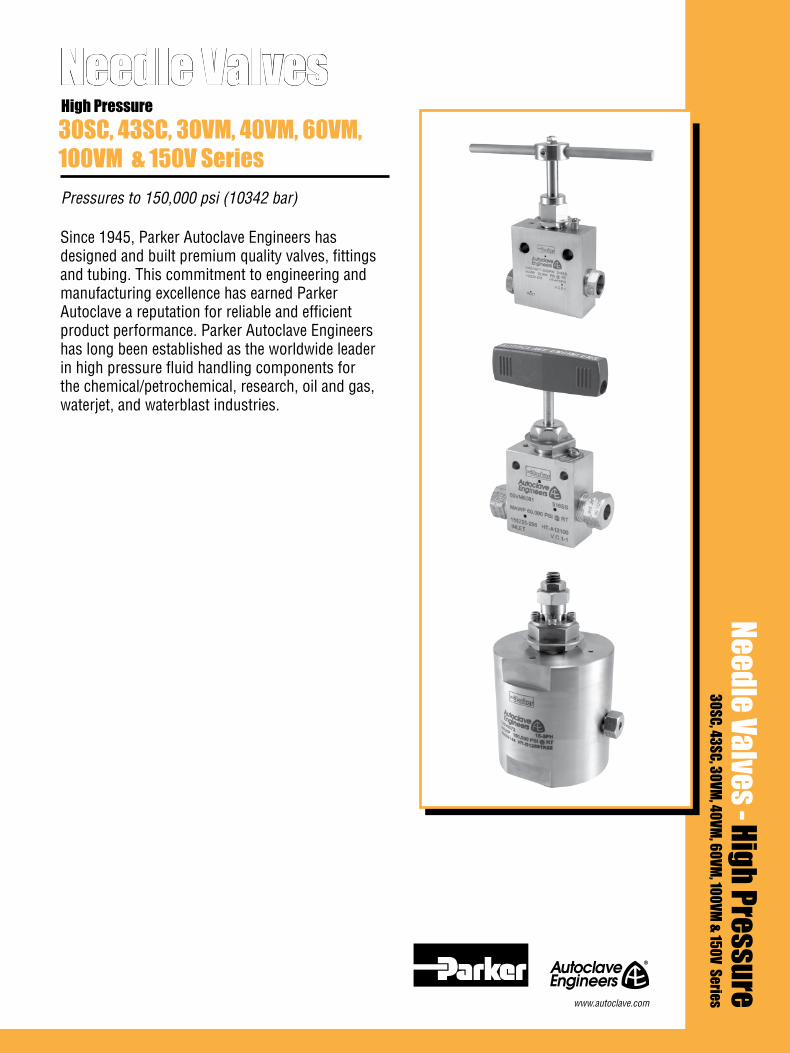
Since 1945, Parker Autoclave Engineers has designed and built premium quality valves, fittings and tubing. This commitment to engineering and manufacturing excellence has earned Parker Autoclave a reputation for reliable and efficient product performance. Parker Autoclave Engineers has long been established as the worldwide leader in high pressure fluid handling components for the chemical/petrochemical, research, oil and gas, waterjet, and waterblast industries.
Needle Valves
Pressures to 150,000 psi (10342 bar)
30SC, 43SC, 30VM, 40VM, 60VM, 100VM & 150V Series
High Pressure
Needle Valves - High Pressure30SC, 43SC, 30VM, 40VM, 60VM, 100VM & 150V Serieswww.autoclave.com

2 All general terms and conditions of sale, including limitations of our liability, apply to all products and services sold.
• Tubing sizes from 1/4” to 1”.
• Non-rotating stem prevents stem/seat galling.
• Rising stem/barstock body design.
• Metal-to-metal seating achieves bubble-tight shut-off, longer stem/seat life in abrasive flow, greater durability for repeated on/off cycles and excellent corrosion resistance.
• For dependable stem and body sealing 30SC, 43SC and 30VM valves are furnished with PTFE encapsulated packing; the 40VM and 60VM valves feature nylon/leather packing below threads.
• Stem sleeve and packing gland materials have been selected to achieve extended thread cycle life and reduced handle torque.
• Choice of Vee or Regulating stem tips.
Series 100VM: Pressures to 100,000 psi (6895 bar) features:
• Cold-worked type 316 or 15-5PH stainless steel body with aluminum bronze packing gland and non-rotating stem.
• Nylon and leather packing below stem threads.
Series 150V: Pressures to 150,000 psi (10342 bar) features:
• Cylindrical body of high strength 15-5PH stainless steel with stainless steel packing gland. Tool steel non- rotating stem with replaceable seat of nickel maraging steel. Stem must be actuated with torque wrench (refer to Tools, Installation, Operation and Maintenance section).
• Wedge-type PTFE and leather packing below stem threads with beryllium-copper Autoclave Anti-Extrusion Back up Rings.
• Vee stem tip only
Parker Autoclave Engineers valves are complemented by a complete line of high pressure fittings and tubing. The high pressure series uses Parker Autoclave Engineers' coned-and-threaded connections for dependable performance in gas or liquid service.
Needle Valves - High PressureHigh Pressure Valve Features

All general terms and conditions of sale, including limitations of our liability, apply to all products and services sold. 3
To ensure proper fit use Autoclave tubing% of rated Cv
100
1
Num
ber o
f tur
ns o
pen
Generalized Flow Coefficient Curves (Cv)
2
3
4
5
6
7
20 30 40 50 60 70 80 90 100
Regulating Stem
Vee Stem
Ordering ProcedureFor complete information on available stem types, optional connections and additional valve options, see Needle Valve Options section or contact your Sales Representative. The 30SC Series valves are furnished complete with connection components, unless otherwise specified.
Typical catalog number: 30SC16071
16-1” 07 - non-rotating Vee stem (on-off service)08 - non-rotating regulating stem (tapered tip for regulating and shutoff)87 - Vee stem with replaceable seat88 - Regulating stem with replaceable seat
1 - two-way straight2 - two-way angle
For extreme temperature and other options,
see Valve Options.
XXOptions
1Body
Pattern
07Stem/Seat
Type
16Outside Diameter
Tube Size
30SCValveSeries
STAINLESS STEEL T-HANDLE
LOCKING DEVICE
NON-ROTATINGSTEM
ADJUSTABLE PACKING BELOW THREADS
HIGH PRESSURE CONED AND THREADEDCONNECTIONS
METAL-TO-METAL SEATING
CHOICE OF VEE OR REGULATING STEM TIP
COLD WORKED TYPE 316 SS BODY IN TWOPATTERNS
ANTI-EXTRUSION BACK-UP RINGS
LOW FRICTION ALUMINUM BRONZE PACKING GLAND
Needle Valves - SC SeriesPressures to 43,000 psi (2965 bar)
Tube Pressure Outside Rating Diameter Orifice psi (bar) Size Connection Size Rated @ Room Inches Type Inches (mm) Cv* Temperature** Series 30SC 1 F1000C43 .438 (11.12) 2.6 30,000 (2068) Series 43SC 1 F1000C43 .438 (11.12) 2.6 43,000 (2965)
Notes: * CV values shown are for 2-way straight valve pattern. For 2-way angle patterns, increase CV value 50%.
** For complete temperature ratings see pressure/temperature rating guide in Technical Information section.
30SC43SC

4 All general terms and conditions of sale, including limitations of our liability, apply to all products and services sold.
2-Way Angle/Replaceable Seat
2-Way Angle
2-Way Straight
Valve Options Valve MaintenanceExtreme Temperatures Standard Parker Autoclave Engineers valves with PTFE packing may be operated from 0°F (-17.8°C) to 450°F (232°C). High temperature packing is available for service from -423°F (-252°C) to 1200°F (649°C) by adding the following suffixes to catalog order number.
TG - standard valve with PTFE glass packing to 600°F (316°C).GY - standard valve with graphite braided yarn packing to 800°F (427°C). 8,000 psi (569 bar) max.HT - extended stuffing box valve with graphite braided yarn packing to 1200°F (649°C).B - standard valve with cryogenic trim material and PTFE packing to -100°F (-73°C).LT - extended stuffing box valve with PTFE packing & Cryogenic trim materials to -423°F (-252°C).K - anti-vibration collet and gland assembly.
Repair Kits: add “R” to the front of valve catalog number for proper repair kit. (Example: R30SC16071)
Valve Bodies: Valve bodies are available. Order using the eight (8) digit part number found in the valve drawing or contact your Sales Representative for information.Consult your Parker Autoclave Engineers representative for pricing on repair kits and valve bodies. Refer to the Tools, Installation, Operation and Maintenance section for proper maintenance procedures.
Dimensions - inches (mm)
30SC16071 VEE 30SC16081 REG
1” 0.438 4.13 2.06 0.72 3.50 2.75 4.44 10.25 1.62 0.56 8.42 1.25 1.12 1.75 (25.40) (11.12) (104.90) (52.32) (18.28) (88.90) (69.85) (112.77) (260.35) (41.14) (14.22) (213.86) (31.75) (28.44) (44.45)
Catalog Number
OutsideDiameter
Tube
OrificeDiameter
StemType
30SC16072 VEE 30SC16082 REG
1” 0.438 4.13 2.06 0.72 2.75 5.12 10.25 1.62 0.56 9.35 1.25 1.12 1.75 (25.40) (11.12) (104.90) (52.32) (18.28) (69.85) (130.04) (260.35) (41.14) (14.22) (237.49) (31.75) (28.44) (44.45)
30SC16872 VEE 30SC16882 REG
1” 0.438 4.13 2.06 0.72 2.75 4.31 5.24 10.25 1.62 0.56 10.56 1.25 1.12 1.75 (25.40) (11.12) (104.90) (52.32) (18.28) (71.37) (109.47) (133.35) (260.35) (41.14) (14.22) (268.22) (31.75) (28.44) (44.45)
H
N
F
G1
G
D
E
M M
A B
C
2-Way Angle 2-Way Angle / Replaceable Seat2-Way Straight
Figure 3Figure 2Figure 1
See Figure 1
See Figure 2
See Figure 3
H
N
F
G1
G
D
E
M M
A B
C
D1
43SC16071 VEE 43SC16081 REG
1” 0.438 4.88 2.44 0.72 3.50 2.75 4.44 10.25 1.62 0.56 8.42 1.25 1.12 2.25 (25.40) (11.12) (123.96) (61.96) (18.28) (88.90) (69.85) (112.77) (260.35) (41.14) (14.22) (213.86) (31.75) (28.44) (57.15)
43SC16072 VEE 43SC16082 REG
1” 0.438 4.88 2.44 0.72 2.75 5.12 10.25 1.62 0.56 9.35 1.25 1.12 2.25 (25.40) (11.12) (123.96) (61.96) (18.28) (69.85) (130.04) (260.35) (41.14) (14.22) (237.49) (31.75) (28.44) (57.15)
43SC16872 VEE 43SC16882 REG
Block Thick- Valve A B C D D1 E F G G1 H* M N ness Pattern
1” 0.438 4.88 2.44 0.72 2.75 4.31 5.24 10.25 1.62 0.56 10.56 1.25 1.12 2.25 (25.40) (11.12) (123.96) (61.96) (18.28) (71.37) (109.47) (133.35) (260.35) (41.14) (14.22) (268.22) (31.75) (28.44) (57.15)
G - Packing gland mounting hole drill size * H Dimension is with stem in closed position. G1 - Bracket mounting hole size All dimensions for reference only and subject to change. Panel mounting drill size: 0.22” all valves.
For prompt service, Parker Autoclave Engineers stock select products. Consult factory.
All general terms and conditions of sale, including limitations of our liability, apply to all products and services sold. 5
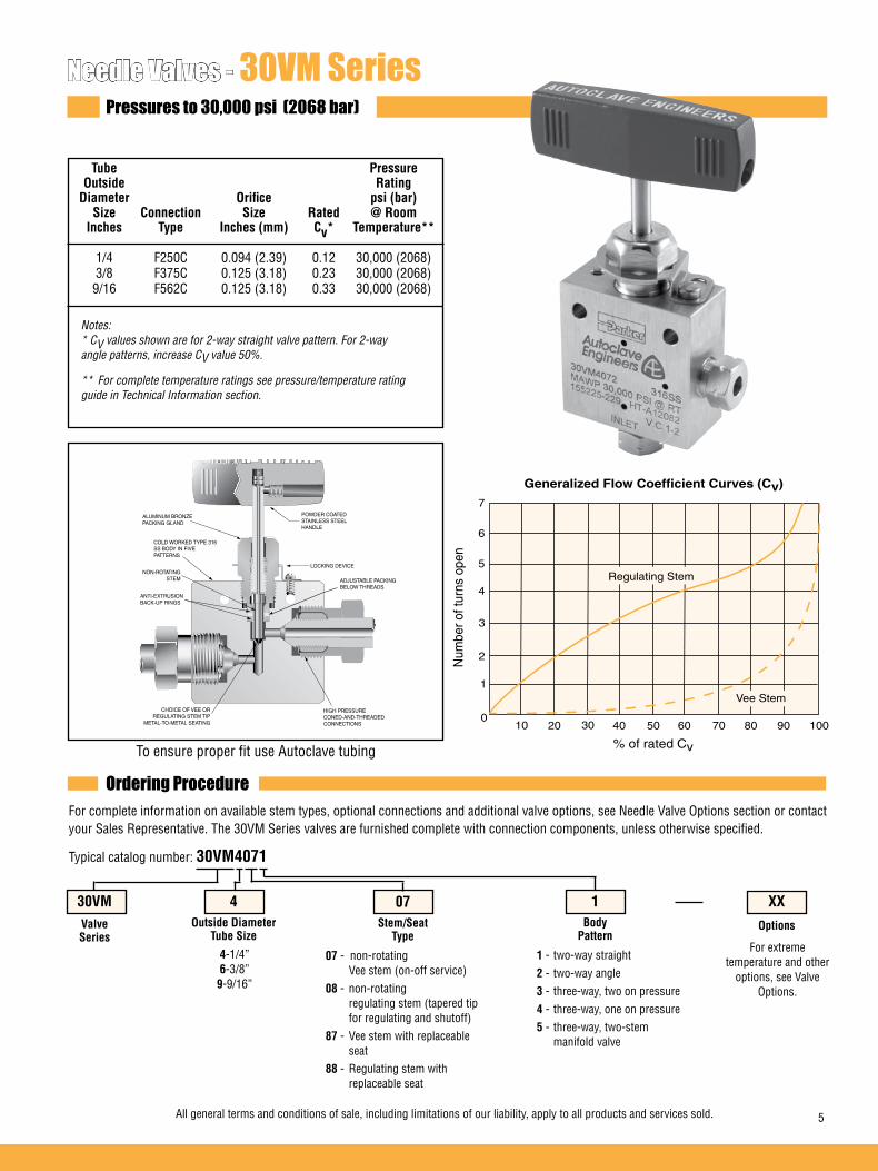
Needle Valves - 30VM SeriesPressures to 30,000 psi (2068 bar)
To ensure proper fit use Autoclave tubing % of rated Cv
100
1
Num
ber o
f tur
ns o
pen
Generalized Flow Coefficient Curves (Cv)
2
3
4
5
6
7
20 30 40 50 60 70 80 90 100
Regulating Stem
Vee Stem
Ordering ProcedureFor complete information on available stem types, optional connections and additional valve options, see Needle Valve Options section or contact your Sales Representative. The 30VM Series valves are furnished complete with connection components, unless otherwise specified.
Typical catalog number: 30VM4071
4-1/4”6-3/8”9-9/16”
07 - non-rotating Vee stem (on-off service)08 - non-rotating regulating stem (tapered tip for regulating and shutoff)87 - Vee stem with replaceable seat88 - Regulating stem with replaceable seat
1 - two-way straight2 - two-way angle3 - three-way, two on pressure4 - three-way, one on pressure5 - three-way, two-stem manifold valve
For extreme temperature and other
options, see Valve Options.
XX
Options
1Body
Pattern
07Stem/Seat
Type
4Outside Diameter
Tube Size
30VMValveSeries
ALUMINUM BRONZE PACKING GLAND
COLD WORKED TYPE 316 SS BODY IN FIVE PATTERNS
NON-ROTATINGSTEM ADJUSTABLE PACKING
BELOW THREADS
LOCKING DEVICE
HIGH PRESSURE CONED-AND-THREADED CONNECTIONS
CHOICE OF VEE OR REGULATING STEM TIP
METAL-TO-METAL SEATING
ANTI-EXTRUSIONBACK-UP RINGS
POWDER COATEDSTAINLESS STEELHANDLE
Tube Pressure Outside Rating Diameter Orifice psi (bar) Size Connection Size Rated @ Room Inches Type Inches (mm) Cv* Temperature** 1/4 F250C 0.094 (2.39) 0.12 30,000 (2068) 3/8 F375C 0.125 (3.18) 0.23 30,000 (2068) 9/16 F562C 0.125 (3.18) 0.33 30,000 (2068)
Notes: * CV values shown are for 2-way straight valve pattern. For 2-way angle patterns, increase CV value 50%.
** For complete temperature ratings see pressure/temperature rating guide in Technical Information section.
6 All general terms and conditions of sale, including limitations of our liability, apply to all products and services sold.
2-Way Straight
2-Way Angle
3-Way / 2 on Pressure
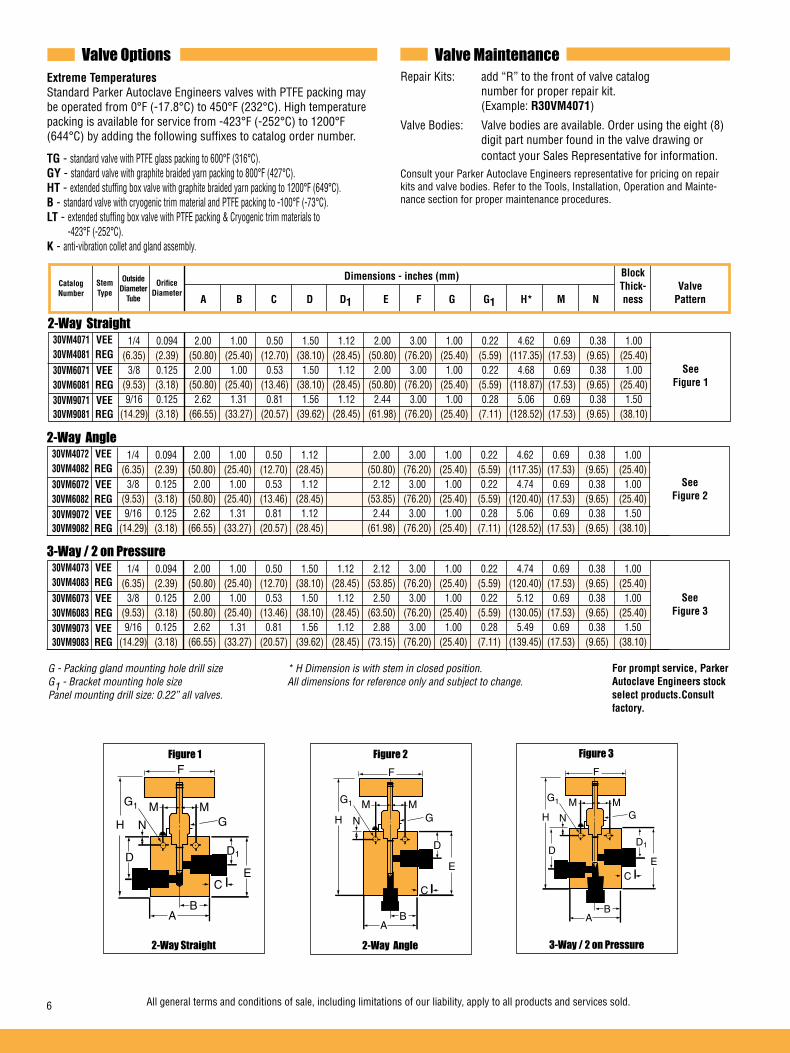
Valve Options Valve MaintenanceExtreme Temperatures Standard Parker Autoclave Engineers valves with PTFE packing may be operated from 0°F (-17.8°C) to 450°F (232°C). High temperature packing is available for service from -423°F (-252°C) to 1200°F (644°C) by adding the following suffixes to catalog order number.
TG - standard valve with PTFE glass packing to 600°F (316°C).GY - standard valve with graphite braided yarn packing to 800°F (427°C).HT - extended stuffing box valve with graphite braided yarn packing to 1200°F (649°C).B - standard valve with cryogenic trim material and PTFE packing to -100°F (-73°C).LT - extended stuffing box valve with PTFE packing & Cryogenic trim materials to -423°F (-252°C).K - anti-vibration collet and gland assembly.
Repair Kits: add “R” to the front of valve catalog number for proper repair kit. (Example: R30VM4071)
Valve Bodies: Valve bodies are available. Order using the eight (8) digit part number found in the valve drawing or contact your Sales Representative for information.Consult your Parker Autoclave Engineers representative for pricing on repair kits and valve bodies. Refer to the Tools, Installation, Operation and Mainte-nance section for proper maintenance procedures.
30VM4071 VEE 30VM4081 REG 30VM6071 VEE 30VM6081 REG 30VM9071 VEE 30VM9081 REG
1/4 0.094 2.00 1.00 0.50 1.50 1.12 2.00 3.00 1.00 0.22 4.62 0.69 0.38 1.00 (6.35) (2.39) (50.80) (25.40) (12.70) (38.10) (28.45) (50.80) (76.20) (25.40) (5.59) (117.35) (17.53) (9.65) (25.40) 3/8 0.125 2.00 1.00 0.53 1.50 1.12 2.00 3.00 1.00 0.22 4.68 0.69 0.38 1.00 (9.53) (3.18) (50.80) (25.40) (13.46) (38.10) (28.45) (50.80) (76.20) (25.40) (5.59) (118.87) (17.53) (9.65) (25.40) 9/16 0.125 2.62 1.31 0.81 1.56 1.12 2.44 3.00 1.00 0.28 5.06 0.69 0.38 1.50 (14.29) (3.18) (66.55) (33.27) (20.57) (39.62) (28.45) (61.98) (76.20) (25.40) (7.11) (128.52) (17.53) (9.65) (38.10)
30VM4072 VEE 30VM4082 REG 30VM6072 VEE 30VM6082 REG 30VM9072 VEE 30VM9082 REG
1/4 0.094 2.00 1.00 0.50 1.12 2.00 3.00 1.00 0.22 4.62 0.69 0.38 1.00 (6.35) (2.39) (50.80) (25.40) (12.70) (28.45) (50.80) (76.20) (25.40) (5.59) (117.35) (17.53) (9.65) (25.40) 3/8 0.125 2.00 1.00 0.53 1.12 2.12 3.00 1.00 0.22 4.74 0.69 0.38 1.00 (9.53) (3.18) (50.80) (25.40) (13.46) (28.45) (53.85) (76.20) (25.40) (5.59) (120.40) (17.53) (9.65) (25.40) 9/16 0.125 2.62 1.31 0.81 1.12 2.44 3.00 1.00 0.28 5.06 0.69 0.38 1.50 (14.29) (3.18) (66.55) (33.27) (20.57) (28.45) (61.98) (76.20) (25.40) (7.11) (128.52) (17.53) (9.65) (38.10)
30VM4073 VEE 30VM4083 REG 30VM6073 VEE 30VM6083 REG 30VM9073 VEE 30VM9083 REG
1/4 0.094 2.00 1.00 0.50 1.50 1.12 2.12 3.00 1.00 0.22 4.74 0.69 0.38 1.00 (6.35) (2.39) (50.80) (25.40) (12.70) (38.10) (28.45) (53.85) (76.20) (25.40) (5.59) (120.40) (17.53) (9.65) (25.40) 3/8 0.125 2.00 1.00 0.53 1.50 1.12 2.50 3.00 1.00 0.22 5.12 0.69 0.38 1.00 (9.53) (3.18) (50.80) (25.40) (13.46) (38.10) (28.45) (63.50) (76.20) (25.40) (5.59) (130.05) (17.53) (9.65) (25.40) 9/16 0.125 2.62 1.31 0.81 1.56 1.12 2.88 3.00 1.00 0.28 5.49 0.69 0.38 1.50 (14.29) (3.18) (66.55) (33.27) (20.57) (39.62) (28.45) (73.15) (76.20) (25.40) (7.11) (139.45) (17.53) (9.65) (38.10)
See Figure 1
See Figure 2
See Figure 3
Dimensions - inches (mm)Orifice
DiameterStemType
H N
F
G1
G
D1DE
M M
AB
C
H N
F
G1
G
D
E
M M
AB
C
H N
F
G1
G
D1
E
M M
AB
C
D
2-Way Angle 3-Way / 2 on Pressure2-Way Straight
Figure 3Figure 2Figure 1
CatalogNumber
Block Thick- Valve A B C D D1 E F G G1 H* M N ness Pattern
OutsideDiameter
Tube
G - Packing gland mounting hole drill size * H Dimension is with stem in closed position. G1 - Bracket mounting hole size All dimensions for reference only and subject to change. Panel mounting drill size: 0.22” all valves.
For prompt service, Parker Autoclave Engineers stock select products.Consult factory.
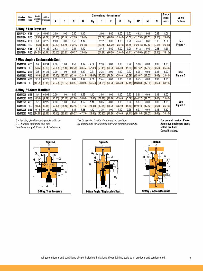
All general terms and conditions of sale, including limitations of our liability, apply to all products and services sold. 7
3-Way / 1 on Pressure
2-Way Angle / Replaceable Seat
3-Way / 2-Stem Manifold
30VM4074 VEE 30VM4084 REG 30VM6074 VEE 30VM6084 REG 30VM9074 VEE 30VM9084 REG
1/4 0.094 2.00 1.00 0.50 1.12 2.00 3.00 1.00 0.22 4.62 0.69 0.38 1.00 (6.35) (2.39) (50.80) (25.40) (12.70) (28.45) (50.80) (76.20) (25.40) (5.59) (117.35) (17.53) (9.65) (25.40) 3/8 0.125 2.00 1.00 0.53 1.12 2.12 3.00 1.00 0.22 4.74 0.69 0.38 1.00 (9.53) (3.18) (50.80) (25.40) (13.46) (28.45) (53.85) (76.20) (25.40) (5.59) (120.40) (17.53) (9.65) (25.40) 9/16 0.125 2.62 1.31 0.81 1.12 2.44 3.00 1.00 0.28 5.12 0.69 0.38 1.50 (14.29) (3.18) (66.55) (33.27) (20.57) (28.45) (61.98) (76.20) (25.40) (7.11) (130.05) (17.53) (9.65) (38.10)
30VM4872 VEE 30VM4882 REG 30VM6872 VEE 30VM6882 REG 30VM9872 VEE 30VM9882 REG
1/4 0.094 2.00 1.00 0.50 1.12 2.06 2.38 3.00 1.00 0.22 5.80 0.69 0.38 1.00 (6.35) (2.39) (50.80) (25.40) (12.70) (28.45) (52.32) (60.45) (76.20) (25.40) (5.59) (147.32) (17.53) (9.65) (25.40) 3/8 0.125 2.00 1.00 0.53 1.12 2.31 2.38 3.00 1.00 0.22 6.05 0.69 0.38 1.00 (9.53) (3.18) (50.80) (25.40) (13.46) (28.45) (58.67) (60.45) (76.20) (25.40) (5.59) (153.67) (17.53) (9.65) (25.40) 9/16 0.125 2.62 1.31 0.81 1.19 2.62 2.44 3.00 1.00 0.28 6.45 0.69 0.38 1.50 (14.29) (3.18) (66.55) (33.27) (20.57) (30.23) (66.55) (61.98) (76.20) (25.40) (7.11) (163.83) (17.53) (9.65) (38.10)
30VM4075 VEE 30VM4085 REG 30VM6075 VEE 30VM6085 REG 30VM9075 VEE 30VM9085 REG
1/4 0.094 2.00 1.00 0.50 1.53 1.12 3.06 3.00 1.00 0.22 5.68 0.69 0.38 1.00 (6.35) (2.39) (50.80) (25.40) (12.70) (38.86) (28.45) (77.72) (76.20) (25.40) (5.59) (144.27) (17.53) (9.65) (25.40) 3/8 0.125 2.00 1.00 0.53 1.62 1.12 3.25 3.00 1.00 0.22 5.87 0.69 0.38 1.00 (9.53) (3.18) (50.80) (25.40) (13.46) (41.15) (28.45) (82.55) (76.20) (25.40) (5.59) (149.10) (17.53) (9.65) (25.40) 9/16 0.125 2.62 1.31 0.81 1.88 1.12 3.75 3.00 1.00 0.28 6.37 0.69 0.38 1.50 (14.29) (3.18) (66.55) (33.27) (20.57) (47.75) (28.45) (95.25) (76.20) (25.40) (7.11) (161.80) (17.53) (9.65) (38.10)
See Figure 4
See Figure 5
See Figure 6
Dimensions - inches (mm)StemType
H
N
F
G1
G
D
E
M M
AB
C
D1
H N
M M
F
G1
G
D1
E
CBA
D1
D
2-Way Angle / Replacable Seat 3-Way / 2-Stem Manifold3-Way / 1 on Pressure
Figure 6Figure 5Figure 4
CatalogNumber
Block Thick- Valve A B C D D1 E F G G1 H* M N ness Pattern
OutsideDiameter
Tube
OrificeDiameter
G - Packing gland mounting hole drill size * H Dimension is with stem in closed position. G1 - Bracket mounting hole size All dimensions for reference only and subject to change. Panel mounting drill size: 0.22” all valves.
For prompt service, Parker Autoclave engineers stock select products. Consult factory.

8 All general terms and conditions of sale, including limitations of our liability, apply to all products and services sold.
Needle Valves - 40VM SeriesPressures to 40,000 psi (2760 bar)
To ensure proper fit use Autoclave tubing
% of rated Cv
100
1
Num
ber o
f tur
ns o
pen
Generalized Flow Coefficient Curves (Cv)
2
3
4
5
6
7
20 30 40 50 60 70 80 90 100
Regulating Stem
Vee Stem
Ordering ProcedureFor complete information on available stem types, optional connections and additional valve options, see Needle Valve Options Section or contact your Sales Representative. The 40VM Series valves are furnished complete with connection components, unless otherwise specified.
Typical catalog number: 40VM9071
9-9/16” 07 - non-rotating Vee stem (on-off service)08 - non-rotating regulating stem (tapered tip for regulating and shutoff)
1 - two-way straight2 - two-way angle5 - three-way, two-stem manifold valve
For extreme temperature and other
options, see Valve Options.
XXOptions
1Body
Pattern
07Stem/Seat
Type
9Outside Diameter
Tube Size
40VMValveSeries
ALUMINUM BRONZE PACKING GLAND
COLD WORKED TYPE 316 SS BODY IN TWO PATTERNS
NON-ROTATINGSTEM
ADJUSTABLE PACKINGBELOW THREADS
LOCKING DEVICE
HIGH PRESSURE CONED-AND-THREADED CONNECTIONS
CHOICE OF VEE OR REGULATING STEM TIP
METAL-TO-METAL SEATING
ANTI-EXTRUSIONBACK-UP RINGS
POWDER COATEDSTAINLESS STEELHANDLE
Tube Pressure Outside Rating Diameter Orifice psi (bar) Size Connection Size Rated @ Room Inches Type Inches (mm) Cv* Temperature** 9/16 F562C40 0.109 (2.77) 0.28 40,000 (2760)
Notes: * CV values shown are for 2-way straight valve pattern. For 2-way angle patterns, increase CV value 50%.
** For complete temperature ratings see pressure/temperature rating guide in Technical Information section.
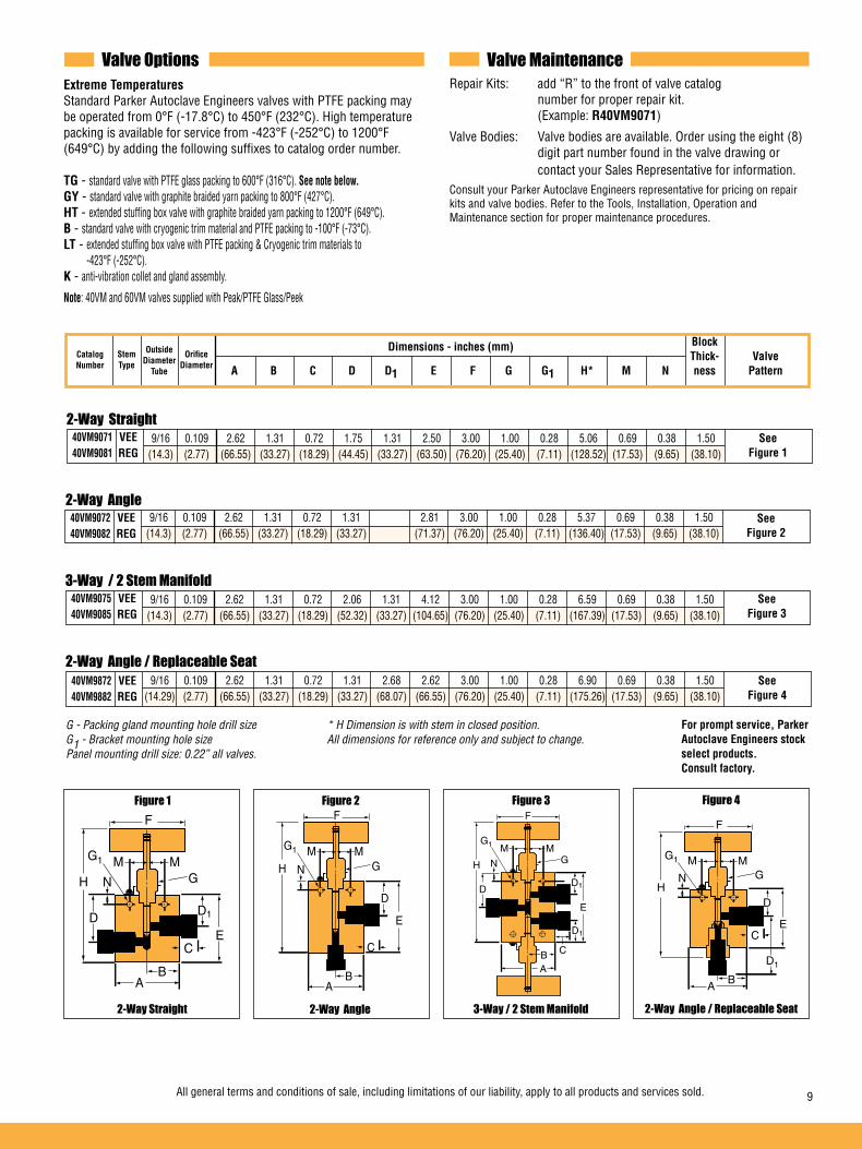
All general terms and conditions of sale, including limitations of our liability, apply to all products and services sold. 9
3-Way / 2 Stem Manifold
2-Way Angle
2-Way Straight
Valve Options Valve MaintenanceExtreme Temperatures Standard Parker Autoclave Engineers valves with PTFE packing may be operated from 0°F (-17.8°C) to 450°F (232°C). High temperature packing is available for service from -423°F (-252°C) to 1200°F (649°C) by adding the following suffixes to catalog order number.
TG - standard valve with PTFE glass packing to 600°F (316°C). See note below.GY - standard valve with graphite braided yarn packing to 800°F (427°C).HT - extended stuffing box valve with graphite braided yarn packing to 1200°F (649°C).B - standard valve with cryogenic trim material and PTFE packing to -100°F (-73°C).LT - extended stuffing box valve with PTFE packing & Cryogenic trim materials to -423°F (-252°C).K - anti-vibration collet and gland assembly.
Note: 40VM and 60VM valves supplied with Peak/PTFE Glass/Peek
Repair Kits: add “R” to the front of valve catalog number for proper repair kit. (Example: R40VM9071)
Valve Bodies: Valve bodies are available. Order using the eight (8) digit part number found in the valve drawing or contact your Sales Representative for information.Consult your Parker Autoclave Engineers representative for pricing on repair kits and valve bodies. Refer to the Tools, Installation, Operation and Maintenance section for proper maintenance procedures.
Dimensions - inches (mm)
40VM9071 VEE 40VM9081 REG
9/16 0.109 2.62 1.31 0.72 1.75 1.31 2.50 3.00 1.00 0.28 5.06 0.69 0.38 1.50 (14.3) (2.77) (66.55) (33.27) (18.29) (44.45) (33.27) (63.50) (76.20) (25.40) (7.11) (128.52) (17.53) (9.65) (38.10)
OutsideDiameter
Tube
OrificeDiameter
StemType
40VM9072 VEE 40VM9082 REG
9/16 0.109 2.62 1.31 0.72 1.31 2.81 3.00 1.00 0.28 5.37 0.69 0.38 1.50 (14.3) (2.77) (66.55) (33.27) (18.29) (33.27) (71.37) (76.20) (25.40) (7.11) (136.40) (17.53) (9.65) (38.10)
H N
F
G1
G
D
E
M M
AB
C
H N
F
G1
G
D1DE
M M
AB
C
2-Way Angle2-Way Straight
Figure 2Figure 1
See Figure 1
See Figure 2
40VM9075 VEE 40VM9085 REG
9/16 0.109 2.62 1.31 0.72 2.06 1.31 4.12 3.00 1.00 0.28 6.59 0.69 0.38 1.50 (14.3) (2.77) (66.55) (33.27) (18.29) (52.32) (33.27) (104.65) (76.20) (25.40) (7.11) (167.39) (17.53) (9.65) (38.10)
See Figure 3
3-Way / 2 Stem Manifold
Figure 3
H N
M M
F
G1
G
D1
E
CBA
D1
D
CatalogNumber
HN
F
G1
G
D
E
M M
AB
C
D1
2-Way Angle / Replaceable Seat
Figure 4
2-Way Angle / Replaceable Seat 40VM9872 VEE 40VM9882 REG
9/16 0.109 2.62 1.31 0.72 1.31 2.68 2.62 3.00 1.00 0.28 6.90 0.69 0.38 1.50 (14.29) (2.77) (66.55) (33.27) (18.29) (33.27) (68.07) (66.55) (76.20) (25.40) (7.11) (175.26) (17.53) (9.65) (38.10)
See Figure 4
Block Thick- Valve A B C D D1 E F G G1 H* M N ness Pattern
G - Packing gland mounting hole drill size * H Dimension is with stem in closed position. G1 - Bracket mounting hole size All dimensions for reference only and subject to change. Panel mounting drill size: 0.22” all valves.
For prompt service, Parker Autoclave Engineers stock select products. Consult factory.
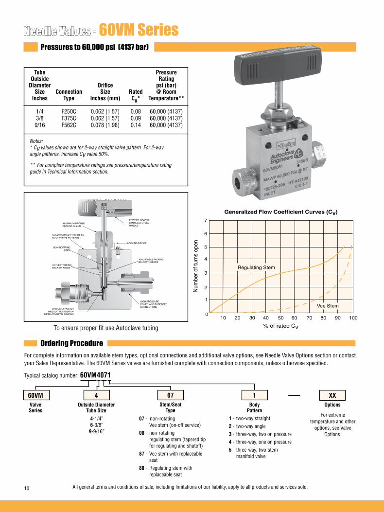
10 All general terms and conditions of sale, including limitations of our liability, apply to all products and services sold.
Needle Valves - 60VM SeriesPressures to 60,000 psi (4137 bar)
To ensure proper fit use Autoclave tubing % of rated Cv
100
1
Num
ber o
f tur
ns o
pen
Generalized Flow Coefficient Curves (Cv)
2
3
4
5
6
7
20 30 40 50 60 70 80 90 100
Regulating Stem
Vee Stem
Ordering ProcedureFor complete information on available stem types, optional connections and additional valve options, see Needle Valve Options section or contact your Sales Representative. The 60VM Series valves are furnished complete with connection components, unless otherwise specified.
Typical catalog number: 60VM4071
4-1/4”6-3/8”9-9/16”
07 - non-rotating Vee stem (on-off service)08 - non-rotating regulating stem (tapered tip for regulating and shutoff)87 - Vee stem with replaceable seat88 - Regulating stem with replaceable seat
1 - two-way straight2 - two-way angle3 - three-way, two on pressure4 - three-way, one on pressure5 - three-way, two-stem manifold valve
For extreme temperature and other
options, see Valve Options.
XXOptions
1Body
Pattern
07Stem/Seat
Type
4Outside Diameter
Tube Size
60VMValveSeries
ALUMINUM BRONZE PACKING GLAND
COLD WORKED TYPE 316 SS BODY IN FIVE PATTERNS
NON-ROTATINGSTEM
ADJUSTABLE PACKINGBELOW THREADS
LOCKING DEVICE
HIGH PRESSURE CONED-AND-THREADED CONNECTIONS
CHOICE OF VEE OR REGULATING STEM TIP
METAL-TO-METAL SEATING
ANTI-EXTRUSIONBACK-UP RINGS
POWDER COATEDSTAINLESS STEELHANDLE
Tube Pressure Outside Rating Diameter Orifice psi (bar) Size Connection Size Rated @ Room Inches Type Inches (mm) Cv* Temperature** 1/4 F250C 0.062 (1.57) 0.08 60,000 (4137) 3/8 F375C 0.062 (1.57) 0.09 60,000 (4137) 9/16 F562C 0.078 (1.98) 0.14 60,000 (4137)
Notes: * CV values shown are for 2-way straight valve pattern. For 2-way angle patterns, increase CV value 50%.
** For complete temperature ratings see pressure/temperature rating guide in Technical Information section.
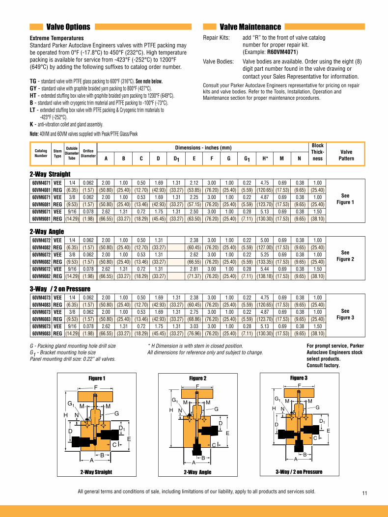
All general terms and conditions of sale, including limitations of our liability, apply to all products and services sold. 11
2-Way Straight
2-Way Angle
3-Way / 2 on Pressure
Valve Options Valve MaintenanceExtreme Temperatures Standard Parker Autoclave Engineers valves with PTFE packing may be operated from 0°F (-17.8°C) to 450°F (232°C). High temperature packing is available for service from -423°F (-252°C) to 1200°F (649°C) by adding the following suffixes to catalog order number.
TG - standard valve with PTFE glass packing to 600°F (316°C). See note below.GY - standard valve with graphite braided yarn packing to 800°F (427°C).HT - extended stuffing box valve with graphite braided yarn packing to 1200°F (649°C).B - standard valve with cryogenic trim material and PTFE packing to -100°F (-73°C).LT - extended stuffing box valve with PTFE packing & Cryogenic trim materials to -423°F (-252°C).K - anti-vibration collet and gland assembly.
Note: 40VM and 60VM valves supplied with Peak/PTFE Glass/Peek
Repair Kits: add “R” to the front of valve catalog number for proper repair kit. (Example: R60VM4071)
Valve Bodies: Valve bodies are available. Order using the eight (8) digit part number found in the valve drawing or contact your Sales Representative for information.Consult your Parker Autoclave Engineers representative for pricing on repair kits and valve bodies. Refer to the Tools, Installation, Operation and Maintenance section for proper maintenance procedures.
60VM4071 VEE 60VM4081 REG 60VM6071 VEE 60VM6081 REG 60VM9071 VEE 60VM9081 REG
1/4 0.062 2.00 1.00 0.50 1.69 1.31 2.12 3.00 1.00 0.22 4.75 0.69 0.38 1.00 (6.35) (1.57) (50.80) (25.40) (12.70) (42.93) (33.27) (53.85) (76.20) (25.40) (5.59) (120.65) (17.53) (9.65) (25.40) 3/8 0.062 2.00 1.00 0.53 1.69 1.31 2.25 3.00 1.00 0.22 4.87 0.69 0.38 1.00 (9.53) (1.57) (50.80) (25.40) (13.46) (42.93) (33.27) (57.15) (76.20) (25.40) (5.59) (123.70) (17.53) (9.65) (25.40) 9/16 0.078 2.62 1.31 0.72 1.75 1.31 2.50 3.00 1.00 0.28 5.13 0.69 0.38 1.50 (14.29) (1.98) (66.55) (33.27) (18.29) (45.45) (33.27) (63.50) (76.20) (25.40) (7.11) (130.30) (17.53) (9.65) (38.10)
60VM4072 VEE 60VM4082 REG 60VM6072 VEE 60VM6082 REG 60VM9072 VEE 60VM9082 REG
1/4 0.062 2.00 1.00 0.50 1.31 2.38 3.00 1.00 0.22 5.00 0.69 0.38 1.00 (6.35) (1.57) (50.80) (25.40) (12.70) (33.27) (60.45) (76.20) (25.40) (5.59) (127.00) (17.53) (9.65) (25.40) 3/8 0.062 2.00 1.00 0.53 1.31 2.62 3.00 1.00 0.22 5.25 0.69 0.38 1.00 (9.53) (1.57) (50.80) (25.40) (13.46) (33.27) (66.55) (76.20) (25.40) (5.59) (133.35) (17.53) (9.65) (25.40) 9/16 0.078 2.62 1.31 0.72 1.31 2.81 3.00 1.00 0.28 5.44 0.69 0.38 1.50 (14.29) (1.98) (66.55) (33.27) (18.29) (33.27) (71.37) (76.20) (25.40) (7.11) (138.18) (17.53) (9.65) (38.10)
60VM4073 VEE 60VM4083 REG 60VM6073 VEE 60VM6083 REG 60VM9073 VEE 60VM9083 REG
1/4 0.062 2.00 1.00 0.50 1.69 1.31 2.38 3.00 1.00 0.22 4.75 0.69 0.38 1.00 (6.35) (1.57) (50.80) (25.40) (12.70) (42.93) (33.27) (60.45) (76.20) (25.40) (5.59) (120.65) (17.53) (9.65) (25.40) 3/8 0.062 2.00 1.00 0.53 1.69 1.31 2.75 3.00 1.00 0.22 4.87 0.69 0.38 1.00 (9.53) (1.57) (50.80) (25.40) (13.46) (42.93) (33.27) (68.86) (76.20) (25.40) (5.59) (123.70) (17.53) (9.65) (25.40) 9/16 0.078 2.62 1.31 0.72 1.75 1.31 3.03 3.00 1.00 0.28 5.13 0.69 0.38 1.50 (14.29) (1.98) (66.55) (33.27) (18.29) (45.45) (33.27) (76.96) (76.20) (25.40) (7.11) (130.30) (17.53) (9.65) (38.10)
See Figure 1
See Figure 2
See Figure 3
Dimensions - inches (mm)OutsideDiameter
Tube
StemType
H N
F
G1
G
D1DE
M M
AB
C
H N
F
G1
G
D
E
M M
AB
C
H N
F
G1
G
D1
E
M M
AB
C
D
2-Way Angle 3-Way / 2 on Pressure2-Way Straight
Figure 3Figure 2Figure 1
CatalogNumber
Block Thick- Valve A B C D D1 E F G G1 H* M N ness Pattern
OrificeDiameter
G - Packing gland mounting hole drill size * H Dimension is with stem in closed position. G1 - Bracket mounting hole size All dimensions for reference only and subject to change. Panel mounting drill size: 0.22” all valves.
For prompt service, Parker Autoclave Engineers stock select products. Consult factory.
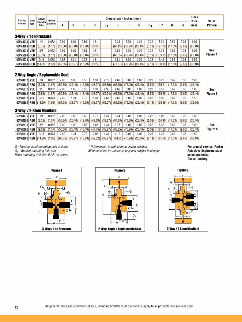
12 All general terms and conditions of sale, including limitations of our liability, apply to all products and services sold.
3-Way / 1 on Pressure
2-Way Angle / Replaceable Seat
3-Way / 2-Stem Manifold
60VM4074 VEE 60VM4084 REG 60VM6074 VEE 60VM6084 REG 60VM9074 VEE 60VM9084 REG
1/4 0.062 2.00 1.00 0.50 1.31 2.38 3.00 1.00 0.22 5.00 0.69 0.38 1.00 (6.35) (1.57) (50.80) (25.40) (12.70) (33.27) (60.45) (76.20) (25.40) (5.59) (127.00) (17.53) (9.65) (25.40) 3/8 0.062 2.00 1.00 0.53 1.31 2.62 3.00 1.00 0.22 5.25 0.69 0.38 1.00 (9.53) (1.57) (50.80) (25.40) (13.46) (33.27) (66.55) (76.20) (25.40) (5.59) (133.35) (17.53) (9.65) (25.40) 9/16 0.078 2.62 1.31 0.72 1.31 2.81 3.00 1.00 0.28 5.44 0.69 0.38 1.50 (14.29) (1.98) (66.55) (33.27) (18.29) (33.27) (71.37) (76.20) (25.40) (7.11) (138.18) (17.53) (9.65) (38.10)
60VM4872 VEE 60VM4882 REG 60VM6872 VEE 60VM6882 REG 60VM9872 VEE 60VM9882 REG
1/4 0.062 2.00 1.00 0.50 1.31 2.12 2.62 3.00 1.00 0.22 6.28 0.69 0.38 1.00 (6.35) (1.57) (50.80) (25.40) (12.70) (33.27) (53.85) (66.55) (76.20) (25.40) (5.59) (159.51) (17.53) (9.65) (25.40) 3/8 0.062 2.00 1.00 0.53 1.31 2.36 2.62 3.00 1.00 0.22 6.52 0.69 0.38 1.00 (9.53) (1.57) (50.80) (25.40) (13.46) (33.27) (59.94) (66.55) (76.20) (25.40) (5.59) (165.60) (17.53) (9.65) (25.40) 9/16 0.078 2.62 1.31 0.72 1.31 2.68 2.62 3.00 1.00 0.28 6.90 0.69 0.38 1.50 (14.29) (1.98) (66.55) (33.27) (18.29) (33.27) (68.07) (66.55) (76.20) (25.40) (7.11) (175.26) (17.53) (9.65) (38.10)
60VM4075 VEE 60VM4085 REG 60VM6075 VEE 60VM6085 REG 60VM9075 VEE 60VM9085 REG
1/4 0.062 2.00 1.00 0.50 1.72 1.31 3.44 3.00 1.00 0.22 6.07 0.69 0.38 1.00 (6.35) (1.57) (50.80) (25.40) (12.70) (43.69) (33.27) (87.38) (76.20) (25.40) (5.59) (154.18) (17.53) (9.65) (25.40) 3/8 0.062 2.00 1.00 0.53 1.88 1.31 3.75 3.00 1.00 0.22 6.37 0.69 0.38 1.00 (9.53) (1.57) (50.80) (25.40) (13.46) (47.75) (33.27) (95.25) (76.20) (25.40) (5.59) (161.80) (17.53) (9.65) (25.40) 9/16 0.078 2.62 1.31 0.72 2.06 1.31 4.12 3.00 1.00 0.28 6.37 0.69 0.38 1.50 (14.29) (1.98) (66.55) (33.27) (18.29) (52.32) (33.27) (104.65) (76.20) (25.40) (7.11) (161.80) (17.53) (9.65) (38.10)
Dimensions - inches (mm)OutsideDiameter
Tube
OrificeDiameter
StemType
See Figure 4
See Figure 5
See Figure 6
HN
F
G1
G
D
E
M M
AB
C
D1
H N
M M
F
G1
G
D1
E
CBA
D1
D
2-Way Angle / Replaceable Seat 3-Way / 2 Stem Manifold3-Way / 1 on Pressure
Figure 6Figure 5Figure 4
H N
F
G1
G
D
E
M M
AB
C
D
CatalogNumber
Block Thick- Valve A B C D D1 E F G G1 H* M N ness Pattern
G - Packing gland mounting hole drill size * H Dimension is with stem in closed position. G1 - Bracket mounting hole size All dimensions for reference only and subject to change. Panel mounting drill size: 0.22” all valves.
For prompt service, Parker Autoclave Engineers stock select products. Consult factory.

All general terms and conditions of sale, including limitations of our liability, apply to all products and services sold. 13
Needle Valves - 100VM & 150V SeriesPressures to 150,000 psi (10350 bar)
To ensure proper fit use Autoclave tubing
100VM Series 150V Series
Notes: Torque wrench required to operate valves.
Tube Pressure Outside Rating Diameter Orifice psi (bar) Size Connection Size Rated @ Room Inches Type Inches (mm) Cv* Temperature** Series 100VM 1/4, 5/16, 3/8 F312C150 0.062 (1.57) .09 100,000 (6895)
Series 150V 5/16 F312C150 0.062 (1.57) .06 150,000 (10342) Notes:
* CV values shown are for 2-way straight valve pattern. For 2-way angle patterns, increase CV value 50%.
** For complete temperature ratings see pressure/temperature rating guide in Technical Information section.
% of rated Cv
100
1
Num
ber
of tu
rns
open
Generalized Flow Coefficient Curves (Cv)
2
3
4
5
6
7
20 30 40 50 60 70 80 90 100
Vee Stem
150V
100VM
ALUMINUM BRONZE PACKING GLAND
NON-ROTATINGSTEM
ADJUSTABLE PACKING BELOW THREADS
LOCKINGDEVICE
15-5PH HIGH STRENGTH STAINLESS STEEL
PACKING GLAND
COLD WORKED 316/15-5PH SS BODY IN THREE PATTERNS
NON-ROTATINGSTEM ADJUSTABLE PACKING
BELOW THREADS
LOCKING DEVICE
METAL-TO-METAL SEATING
ANTI-EXTRUSIONBACK-UP RINGS
POWDER COATEDSTAINLESS STEELHANDLE

14 All general terms and conditions of sale, including limitations of our liability, apply to all products and services sold.
2-Way Straight
2-Way Angle
H N
F
G1
G
D1DE
M M
AB
C
2-Way Angle2-Way Straight
Figure 2Figure 1
Ordering ProcedureFor complete information on available stem types, optional connections and additional valve options, see Needle Valve Options section or contact your Sales Representative. The 100V Series valves are furnished complete with connection components, unless otherwise specified.
Typical catalog number: 100VM5071
*4-1/4”5-5/16” *6-3/8”
07 - non-rotating Vee stem (on off service)08 - non-rotating regulating stem (tapered tip for regulating shutoff
1 - two-way straight2 - two-way angle3 - three-way, two on pressure
For extreme temperature and other
options, see Valve Options.
XXOptions
1Body
Pattern
07StemType
5Outside Diameter
Tube Size
100VMValveSeries
100VM150V
Block Thick- Valve A B C D D1 E F G G1 H* M N ness Pattern
Dimensions - inches (mm)Catalog Number
OutsideDiameter
Tube
OrificeDiameter
StemType
100VM4071 100VM5071 VEE 100VM6071
0.062 3.00 1.50 0.52 1.75 1.44 2.25 4.00 1.12 0.34 5.32 1.12 0.50 1.38 (1.57) (76.20) (38.10) (13.21) (44.45) (36.58) (57.15) (101.60) (28.45) (8.64) (135.13) (28.45) (12.70) (35.05)
0.062 2.25 1.50 0.52 1.44 3.00 4.00 1.12 0.34 6.05 0.94 0.50 1.38 (1.57) (57.15) (38.10) (13.21) (36.58) (76.20) (101.60) (28.45) (8.64) (153.67) (23.88) (12.70) (35.05)
See Figure 2
See Figure 1
Valve Options Valve MaintenanceExtreme Temperatures Standard Parker Autoclave Engineers valves with PTFE packing may be operated to 450°F (232°C), and to 230°F (110°C) with nylon-leather packing. K - anti-vibration collet and gland assembly.
For other packing options consult the factory.
Repair Kits: add “R” to the front of valve catalog number for proper repair kit. (Example: R100VM15071)
Valve Bodies: Valve bodies are available. Order using the eight (8) digit part number found in the valve drawing or contact your Sales Representative for information.Consult your Parker Autoclave Engineers representative for pricing on repair kits and valve bodies. Refer to the Tools, Installation, Operation and Maintenance section for proper maintenance procedures.
* Note: 1/4" and 3/8" for 100VM only.
100VM4072 100VM5072 VEE 100VM6072
1/4" (6.35)5/16" (7.93) 3/8" (9.53)
1/4" (6.35)5/16" (7.93) 3/8" (9.53)
H N
F
G
D
E
M
AB
C
G1
G - Packing gland mounting hole drill size * H Dimension is with stem in closed position. G1 - Bracket mounting hole size All dimensions for reference only and subject to change. Panel mounting drill size: 0.22” all valves.
For prompt service, Parker Autoclave Engineers stock select products. Consult factory.

All general terms and conditions of sale, including limitations of our liability, apply to all products and services sold. 15
2-Way Angle / Replaceable Seat
3-Way / 2 On Pressure
2-Way Angle/Replaceable Seat
H N
F
G1
G
D1
E
M M
AB
C
D
3-Way / 2 on Pressure
Figure 3
2-Way Angle / Replaceable Seat
Figure 4
150V5072 VEE
5/16 0.062 3.75 1.88 .052 2.25 2.63 4.00 1.650 7.12 1.25= (7.93) (1.57) (95.25) (47.63) (13.21) (57.15) (66.80) (101.60) (41.91) (180.85) (31.75)
See Figure 5
Dimensions - inches (mm)Catalog Number
OutsideDiameter
Tube
OrificeDiameter
StemType
0.062 3.00 1.50 0.52 1.75 1.44 3.25 4.00 1.12 0.34 6.31 1.12 0.50 1.38 (1.57) (76.20) (38.10) (13.21) (44.45) (36.58) (82.55) (101.60) (28.45) (8.64) (160.27) (28.45) (12.70) (35.05)
See Figure 3
100VM4073 100VM5073 VEE 100VM6073
1/4" (6.35) 5/16" (7.93) 3/8" (9.53)
2-Way Angle / Replaceable Seat
Figure 5
HD
A DiameterB
E
D1
C
G=M
0.062 2.25 1.50 0.52 1.44 3.00 4.00 1.12 0.34 7.57 0.94 0.50 1.38 (1.57) (57.15) (38.10) (13.21) (36.58) (76.20) (101.60) (28.45) (8.64) (192.30) (23.88) (12.70) (35.05)
See Figure 4
100VM4872 100VM5872 VEE 100VM6872
H N
F
G
E
M
AB
C
G1
D1
= (2) 1/4"-20 mounting holes 180 apart and (1) locking device screw 90 apart
1/4" (6.35) 5/16" (7.93) 3/8" (9.53)
Block Thick- Valve A B C D D1 E F G G1 H* M N ness Pattern
G - Packing gland mounting hole drill size * H Dimension is with stem in closed position. G1 - Bracket mounting hole size All dimensions for reference only and subject to change. Panel mounting drill size: 0.22” all valves.See mounting note below for 150V series.
For prompt service, Parker Autoclave Engineers stock select products. Consult factory.

02-0113SE January2013© 2013 Parker Hannifin Corporation | Autoclave Engineers is a registered trademark of the Parker Hannifin Corporation
Parker Hannifin Manufacturing Ltd. Instrumentation Products Division, Europe Industrial Estate WhitemillWexford, Republic of IrelandPH: 353 53 914 1566FAX: 353 53 914 1582
Instrumentation Products DivisionAutoclave Engineers Operation8325 Hessinger DriveErie, Pennsylvania 16509-4679 USAPH: 814-860-5700 FAX: 814-860-5811www.autoclave.com
WARNINGFAILURE, IMPROPER SELECTION OR IMPROPER USE OF THE PRODUCTS AND/OR SYSTEMS DESCRIBED HEREIN OR RELATED ITEMS CAN CAUSE DEATH, PERSONAL INJURY AND PROPERTY DAMAGE.This document and other information from Parker Hannifin Corporation, its subsidiaries and authorized distributors provide product and/or system options for further investiga-tion by users having technical expertise. It is important that you analyze all aspects of your application and review the information concerning the product or system in the current product catalog. Due to the variety of operating conditions and applications for these products or systems, the user, through its own analysis and testing, is solely responsible for making the final selection of the products and systems and assuring that all performance, safety and warning requirements of the application are met. The products described herein, including without limitation, product features, specifications, designs, availability and pricing, are subject to change by Parker Hannifin Corporation and its subsidiaries at any time without notice.
Offer of SaleThe items described in this document are available for sale by Parker Hannifin Corporation, its subsidiaries or its authorized distributors. Any sale contract entered by Parker will begoverned by the provisions stated in Parker's standard terms and conditions of sale (copy available upon request).
ISO-9001 Certified
Caution! Do not mix or interchange parts or tubing with those of other manufacturers. Doing so is unsafe and will void warranty.
Caution! Parker Autoclave Engineers Valves, Fittings and Tools are not designed to work with common commercial instrument tubing and will only work with tubing built to Parker Autoclave Engineers AES Specifications. Failure to do so will void warranty.

All general terms and conditions of sale, including limitations of our liability, apply to all products and services sold. 1
Needle Valves - P Pipe Valve SeriesNeedle Valves
Pressures to 15,000 psi (1034 bar)
P SeriesPipe Valves
Since 1945 Parker Autoclave Engineers has designed and built premium quality valves, fittings and tubing. This commitment to engineering and manufacturing excellence has earned Parker Autoclave Engineers a reputation for reliable efficient product performance. Parker Autoclave Engineers has long been established as the world leader in high pressure fluid handling components for the chemical/petrochemical, research, and oil and gas industries.
Pipe Valve Features:
• P Series valve design provides in-line pipe connections for 1/4” to 1” pipe sizes. 1/8 connections offset.
• Rising stem/barstock body design.• Non-rotating stem prevents stem/seat galling (1/8" NPT rotating stem design).
• Metal-to-metal seating achieves bubble-tight shut-off, longer stem/seat life in abrasive flow, greater durability for repeated on/off cycles and excellent corrosion resistance.
• PTFE encapsulated packing provides dependable stem and body sealing.
• Stem sleeve and packing gland materials have been selected to achieve extended thread cycle life and reduced handle torque.
• Choice of Vee or Regulating stem tips.
• Operating temperature range from -423°F (-252°C) to 400°F (204°C).
Parker Autoclave Engineers valves are complemented by a complete line of fittings, tubing, check valves and line filters.
www.autoclave.com

All general terms and conditions of sale, including limitations of our liability, apply to all products and services sold.2
Valve Series - P SeriesPressures to 15,000 psi (1034 bar)
Ordering ProcedureFor complete information on available stem types, optional connections and additional valve options, see Needle Valve Options section or contact your Sales Representative.
Typical catalog number: 15P4071
2-1/8”4-1/4”6-3/8”8-1/2”12-3/4” 16-1”
00 - rotating Vee stem (on-off service) 01 - rotating regulating stem (tapered tip for regulating and shut off) 07 - non-rotating Vee stem (on-off service) 08 - non-rotating regulating stem (tapered tip for regulating and shutoff)
1 - two-way straight
2 - two-way angle3 - three-way, two on pressure4 - three-way, one on pressure5 - three-way, two stem manifold valve
1Body
Pattern
07Stem/Seat
Type
4NominalPipe Size
15PValveSeries
Tube Pressure Outside Rating Diameter Orifice psi (bar) Size Connection Size Rated @ Room Inches Type Inches (mm) Cv* Temperature** 1/8 Pipe 0.078 (1.98) 0.11 15,000 (1034) 1/4 Pipe 0.203 (5.16) 0.63 15,000 (1034) 3/8 Pipe 0.219 (5.56) 0.75 15,000 (1034) 1/2 Pipe 0.312 (7.92) 1.30 15,000 (1034) 3/4 Pipe 0.438 (11.13) 2.50 10,000 (690) 1 Pipe 0.562 (14.27) 4.40 10,000 (690)
Notes: * CV values shown are for 2-way straight valve pattern. For 2-way angle patterns, increase CV value 50%. (Based on water)** For complete temperature ratings see pressure/temperature rating guide in Technical Information section.
Generalized Flow Coefficient Curves (Cv)
% of rated Cv
Num
ber
of tu
rns
open
10 20 30 40 50 60 70 80 90 100
7
6
5
4
3
2
1
0
Regulating Stem
Vee Stem
LOW FRICTION ALUMINUM BRONZE PACKING GLAND
COLD WORKED TYPE 316 SS BODY IN FIVE PATTERNS
NON-ROTATING STEMROTATING STEM FOR 1/8”
ADJUSTABLE PACKINGBELOW THREADS
LOCKING DEVICE
PIPE CONNECTIONMETAL-TO-METAL
SEATING
CHOICE OF VEE OR REGULATING STEM TIP
ANTI-EXTRUSIONBACK-UP RINGS
POWDER COATEDSTAINLESS STEELHANDLE
10P-10,000 psi (690 bar)15P-15,000 psi (1034 bar)
Note: 3/4" and 1" 10,000 psi (690 bar) max.
For extreme temperature and other options, see Valve Options.
XXOptions
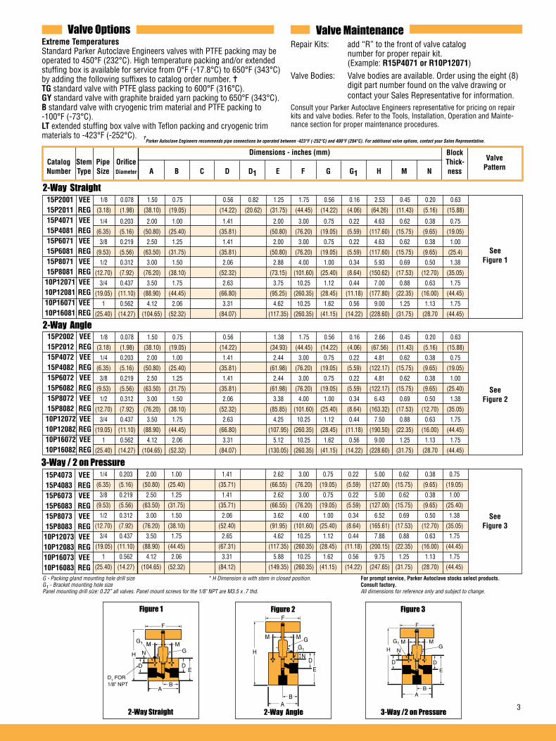
All general terms and conditions of sale, including limitations of our liability, apply to all products and services sold. 3
Parker Autoclave Engineers recommends pipe connections be operated between -423°F (-252°C) and 400°F (204°C). For additional valve options, contact your Sales Representative.
Valve Options Valve MaintenanceRepair Kits: add “R” to the front of valve catalog number for proper repair kit. (Example: R15P4071 or R10P12071)Valve Bodies: Valve bodies are available. Order using the eight (8) digit part number found on the valve drawing or contact your Sales Representative for information.Consult your Parker Autoclave Engineers representative for pricing on repair kits and valve bodies. Refer to the Tools, Installation, Operation and Mainte-nance section for proper maintenance procedures.
G - Packing gland mounting hole drill size * H Dimension is with stem in closed position. For prompt service, Parker Autoclave stocks select products. G1 - Bracket mounting hole size Consult factory.Panel mounting drill size: 0.22” all valves. Panel mount screws for the 1/8" NPT are M3.5 x .7 thd. All dimensions for reference only and subject to change.
Dimensions - inches (mm)
Figure 1
2-Way Straight
Block Catalog Stem Pipe Orifice Thick- Number Type Size Diameter A B C D D1 E F G G1 H M N ness
ValvePattern
2-Way Straight
See Figure 1
2-Way Angle
See Figure 2
H
F
G1
G
D
E
A
M
B
M
N
Figure 2
2-Way Angle
3-Way / 2 on Pressure 15P4073 VEE 15P4083 REG 15P6073 VEE 15P6083 REG 15P8073 VEE 15P8083 REG 10P12073 VEE 10P12083 REG 10P16073 VEE 10P16083 REG
See Figure 3
Figure 3
H
F
G1G
E
AB
M M
N
D D
3-Way /2 on Pressure
1/4 0.203 2.00 1.00 1.41 2.44 3.00 0.75 0.22 4.81 0.62 0.38 0.75
(6.35) (5.16) (50.80) (25.40) (35.81) (61.98) (76.20) (19.05) (5.59) (122.17) (15.75) (9.65) (19.05)
3/8 0.219 2.50 1.25 1.41 2.44 3.00 0.75 0.22 4.81 0.62 0.38 1.00
(9.53) (5.56) (63.50) (31.75) (35.81) (61.98) (76.20) (19.05) (5.59) (122.17) (15.75) (9.65) (25.40)
1/2 0.312 3.00 1.50 2.06 3.38 4.00 1.00 0.34 6.43 0.69 0.50 1.38
(12.70) (7.92) (76.20) (38.10) (52.32) (85.85) (101.60) (25.40) (8.64) (163.32) (17.53) (12.70) (35.05)
3/4 0.437 3.50 1.75 2.63 4.25 10.25 1.12 0.44 7.50 0.88 0.63 1.75
(19.05) (11.10) (88.90) (44.45) (66.80) (107.95) (260.35) (28.45) (11.18) (190.50) (22.35) (16.00) (44.45)
1 0.562 4.12 2.06 3.31 5.12 10.25 1.62 0.56 9.00 1.25 1.13 1.75
(25.40) (14.27) (104.65) (52.32) (84.07) (130.05) (260.35) (41.15) (14.22) (228.60) (31.75) (28.70 (44.45)
1/4 0.203 2.00 1.00 1.41 2.62 3.00 0.75 0.22 5.00 0.62 0.38 0.75
(6.35) (5.16) (50.80) (25.40) (35.71) (66.55) (76.20) (19.05) (5.59) (127.00) (15.75) (9.65) (19.05)
3/8 0.219 2.50 1.25 1.41 2.62 3.00 0.75 0.22 5.00 0.62 0.38 1.00
(9.53) (5.56) (63.50) (31.75) (35.71) (66.55) (76.20) (19.05) (5.59) (127.00) (15.75) (9.65) (25.40)
1/2 0.312 3.00 1.50 2.06 3.62 4.00 1.00 0.34 6.52 0.69 0.50 1.38
(12.70) (7.92) (76.20) (38.10) (52.40) (91.95) (101.60) (25.40) (8.64) (165.61) (17.53) (12.70) (35.05)
3/4 0.437 3.50 1.75 2.65 4.62 10.25 1.12 0.44 7.88 0.88 0.63 1.75
(19.05) (11.10) (88.90) (44.45) (67.31) (117.35) (260.35) (28.45) (11.18) (200.15) (22.35) (16.00) (44.45)
1 0.562 4.12 2.06 3.31 5.88 10.25 1.62 0.56 9.75 1.25 1.13 1.75
(25.40) (14.27) (104.65) (52.32) (84.12) (149.35) (260.35) (41.15) (14.22) (247.65) (31.75) (28.70) (44.45)
1/4 0.203 2.00 1.00 1.41 2.00 3.00 0.75 0.22 4.63 0.62 0.38 0.75
(6.35) (5.16) (50.80) (25.40) (35.81) (50.80) (76.20) (19.05) (5.59) (117.60) (15.75) (9.65) (19.05)
3/8 0.219 2.50 1.25 1.41 2.00 3.00 0.75 0.22 4.63 0.62 0.38 1.00
(9.53) (5.56) (63.50) (31.75) (35.81) (50.80) (76.20) (19.05) (5.59) (117.60) (15.75) (9.65) (25.4)
1/2 0.312 3.00 1.50 2.06 2.88 4.00 1.00 0.34 5.93 0.69 0.50 1.38
(12.70) (7.92) (76.20) (38.10) (52.32) (73.15) (101.60) (25.40) (8.64) (150.62) (17.53) (12.70) (35.05)
3/4 0.437 3.50 1.75 2.63 3.75 10.25 1.12 0.44 7.00 0.88 0.63 1.75
(19.05) (11.10) (88.90) (44.45) (66.80) (95.25) (260.35) (28.45) (11.18) (177.80) (22.35) (16.00) (44.45)
1 0.562 4.12 2.06 3.31 4.62 10.25 1.62 0.56 9.00 1.25 1.13 1.75
(25.40) (14.27) (104.65) (52.32) (84.07) (117.35) (260.35) (41.15) (14.22) (228.60) (31.75) (28.70 (44.45)
1/8 0.078 1.50 0.75 0.56 0.82 1.25 1.75 0.56 0.16 2.53 0.45 0.20 0.63
(3.18) (1.98) (38.10) (19.05) (14.22) (20.62) (31.75) (44.45) (14.22) (4.06) (64.26) (11.43) (5.16) (15.88)
1/8 0.078 1.50 0.75 0.56 1.38 1.75 0.56 0.16 2.66 0.45 0.20 0.63
(3.18) (1.98) (38.10) (19.05) (14.22) (34.93) (44.45) (14.22) (4.06) (67.56) (11.43) (5.16) (15.88)
H N
MM M
F
G1
G
DE
BA
D
D1 FOR 1/8” NPT
15P2001 VEE 15P2011 REG 15P4071 VEE 15P4081 REG 15P6071 VEE 15P6081 REG 15P8071 VEE 15P8081 REG 10P12071 VEE 10P12081 REG 10P16071 VEE 10P16081 REG
15P2002 VEE 15P2012 REG 15P4072 VEE 15P4082 REG 15P6072 VEE 15P6082 REG 15P8072 VEE 15P8082 REG 10P12072 VEE 10P12082 REG 10P16072 VEE 10P16082 REG
Extreme Temperatures Standard Parker Autoclave Engineers valves with PTFE packing may be operated to 450°F (232°C). High temperature packing and/or extended stuffing box is available for service from 0°F (-17.8°C) to 650°F (343°C) by adding the following suffixes to catalog order number. TG standard valve with PTFE glass packing to 600°F (316°C).GY standard valve with graphite braided yarn packing to 650°F (343°C).B standard valve with cryogenic trim material and PTFE packing to -100°F (-73°C). LT extended stuffing box valve with Teflon packing and cryogenic trim materials to -423°F (-252°C).

02-1251SE January2013© 2013 Parker Hannifin Corporation | Autoclave Engineers is a registered trademark of the Parker Hannifin Corporation
Parker Hannifin Manufacturing Ltd. Instrumentation Products Division, Europe Industrial Estate WhitemillWexford, Republic of IrelandPH: 353 53 914 1566FAX: 353 53 914 1582
Instrumentation Products DivisionAutoclave Engineers Operation8325 Hessinger DriveErie, Pennsylvania 16509-4679 USAPH: 814-860-5700 FAX: 814-860-5811www.autoclave.com
WARNING
FAILURE, IMPROPER SELECTION OR IMPROPER USE OF THE PRODUCTS AND/OR SYSTEMS DESCRIBED HEREIN OR RELATED ITEMS CAN CAUSE DEATH, PERSONAL INJURY AND PROPERTY DAMAGE.This document and other information from Parker Hannifin Corporation, its subsidiaries and authorized distributors provide product and/or system options for further investigation by users having technical expertise. It is important that you analyze all aspects of your application and review the information concerning the product or system in the current product catalog. Due to the variety of operating conditions and applications for these products or systems, the user, through its own analysis and testing, is solely responsible for making the final selection of the products and systems and assuring that all performance, safety and warning requirements of the application are met. The products described herein, including without limitation, product features, specifications, designs, availability and pricing, are subject to change by Parker Hannifin Corporation and its subsidiaries at any time without notice.
Offer of Sale
The items described in this document are available for sale by Parker Hannifin Corporation, its subsidiaries or its authorized distributors. Any sale contract entered by Parker will be governed by the provisions stated in Parker's standard terms and conditions of sale (copy available upon request).
ISO-9001 Certified
Caution! Do not mix or interchange parts or tubing with those of other manufacturers. Doing so is unsafe and will void warranty.
Caution! Parker Autoclave Engineers Valves, Fittings and Tools are not designed to work with common commercial instrument tubing and will only work with tubing built to Parker Autoclave Engineers AES Specifications. Failure to do so will void warranty.
G - Packing gland mounting hole drill size *H Dimension is with stem in closed position. For prompt service, Parker G1 - Bracket mounting hole size All dimensions for reference only and subject to change. Autoclave Engineers stocks select Panel mounting drill size: 0.22” all valves. products. Consult factory.
3-Way/2-Stem Manifold 15P4075 VEE 15P4085 REG 15P6075 VEE 15P6085 REG 15P8075 VEE 15P8085 REG 10P12075 VEE 10P12085 REG 10P16075 VEE 10P16085 REG
1/4 0.203 2.00 1.00 1.69 1.19 3.38 3.00 0.75 0.22 5.75 0.62 0.38 0.75
(6.35) (5.16) (50.80) (25.40) (42.88) (30.18) (85.85) (76.20) (19.05) (5.59) (146.05) (15375) (9.65) (19.05)
3/8 0.219 2.50 1.25 1.69 1.19 3.38 3.00 0.75 0.22 5.75 0.62 0.38 1.00
(9.53) (5.56) (63.50) (31.75) (42.88) (30.18) (85.85) (76.20) (19.05) (5.59) (146.05) (15.75) (9.65) (25.40)
1/2 0.312 3.00 1.50 2.56 1.75 5.12 4.00 1.00 0.34 8.05 0.69 0.50 1.38
(12.70) (7.92) (76.20) (38.10) (65.07) (44.45) (130.05) (101.60) (25.40) (8.64) (204.47) (17.53) (12.70) (35.05)
3/4 0.437 3.50 1.75 3.25 2.25 6.50 10.25 1.12 0.44 9.75 0.88 0.63 1.75
(19.05) (11.10) (88.90) (44.45) (82.55) (57.15) (165.10) (260.35) (28.45) (11.18) (247.65) (22.35) (16.00) (44.45)
1 0.562 4.12 2.06 3.75 2.81 7.50 10.25 1.62 0.56 11.47 1.25 1.13 1.75
(25.40) (14.27) (104.65) (52.32) (95.25) (71.42) (190.50) (260.35) (41.15) (14.22) (291.38) (31.75) (28.70) (44.45)
3-Way / 1 on Pressure 15P4074 VEE 15P4084 REG 15P6074 VEE 15P6084 REG 15P8074 VEE 15P8084 REG 10P12074 VEE 10P12084 REG 10P16074 VEE 10P16084 REG
1/4 .0203 2.00 1.00 1.41 2.44 3.00 0.75 0.22 4.81 0.62 0.38 0.75
(6.35) (5.16) (50.80) (25.40) (35.71) (61.98) (76.20) (19.05) (5.59) (122.17) (15.75) (9.65) (19.05)
3/8 0.219 2.50 1.25 1.41 2.44 3.00 0.75 0.22 4.81 0.62 0.38 1.00
(9.53) (5.56) (63.50) (31.75) (35.71) (61.98) (76.20) (19.05) (5.59) (122.17) (15.75) (9.65) (25.40)
1/2 0.312 3.00 1.50 2.06 3.38 4.00 1.00 0.34 6.31 0.69 0.50 1.38
(12.70) (7.92) (76.20) (38.10) (52.40) (85.85) (101.60) (25.40) (8.64) (160.27) (17.53) (12.70) (35.05)
3/4 0.437 3.50 1.75 2.65 4.25 10.25 1.12 0.44 7.50 0.88 0.63 1.75
(19.05) (11.10) (88.90) (44.45) (67.31) (107.95) (260.35) (28.45) (11.18) (190.50) (22.35) (16.00) (44.45)
1 0.562 4.12 2.06 3.31 5.12 10.25 1.62 0.56 9.09 1.25 1.13 1.75
(25.40) (14.27) (104.65) (52.32) (84.07) (130.05) (260.35) (41.15) (14.22) (230.89) (31.75) (28.70) (44.45)
Dimensions - inches (mm)Outside
H N
M M
F
G1
G
DDE
BA
H
F
G1G
E
AB
M M
N
D D
See Figure 5
See Figure 4
Block Catalog Stem Diameter Orifice Thick- Number Type Tube Diameter A B C D D1 E F G G1 H* M N ness
Valve Pattern
3-Way/1 on Pressure
Figure 4
3-Way/2-Stem Manifold
Figure 5NOTE: NPT (Pipe) Connections:- NPT threads must be sealed using a high quality PTFE tape and/or paste product. Refer to thread sealant manufacturer's instructions on how to apply thread sealant.- Sealing performance may vary based on many factors such as pressure, temperature, media, thread quality, thread material, proper thread engagement and proper use of thread sealant.- Customer should limit the number of times an NPT fitting is assembled and disassembled because thread deformation during assembly will result in deteriorating seal quality over time. When using only PTFE tape, consider using thread lubrication to prevent galling of mating parts.

Since 1945 Parker Autoclave Engineers has designed and built premium quality valves, fittings and tubing. This commitment to engineering and manufacturing excellence has earned Parker Autoclave a reputation for reliable efficient product performance. Parker Autoclave Engineers has long been established as the world leader in high pressure fluid handling components for the chemical/petrochemical, research, and oil and gas industries.
Mini Valve Features:
• Mini valve provides a rugged compact design.
• Tubing sizes available are 1/16” and 1/8”.
• Rising stem/barstock body design.
• Metal-to-metal seating achieves bubble-tight shut-off, longer stem/seat life in abrasive flow, greater durability for repeated on/off cycles and excellent corrosion resistance.
• PTFE encapsulated packing provides dependable stem and body sealing.
• Stem and packing gland design have been selected to achieve extended thread cycle life and reduced handle torque.
• Vee stem tip provided.
• Available in five body patterns.
• Mini valves available with metric tube glands.
Parker Autoclave Engineers valves are complemented by a complete line of mini fittings and tubing. The MVE/MV Series uses Parker Autoclave Engineers' SpeedBite connection. This single-ferrule compression sleeve connection delivers fast, easy make-up and reliable bubble-tight performance in liquid or gas service.
Needle Valves
Pressures to 15,000 psi (1034 bar)
MVE/MV SeriesMini Valves
Needle Valves - MVE/MV SeriesMini Valves
www.autoclave.com
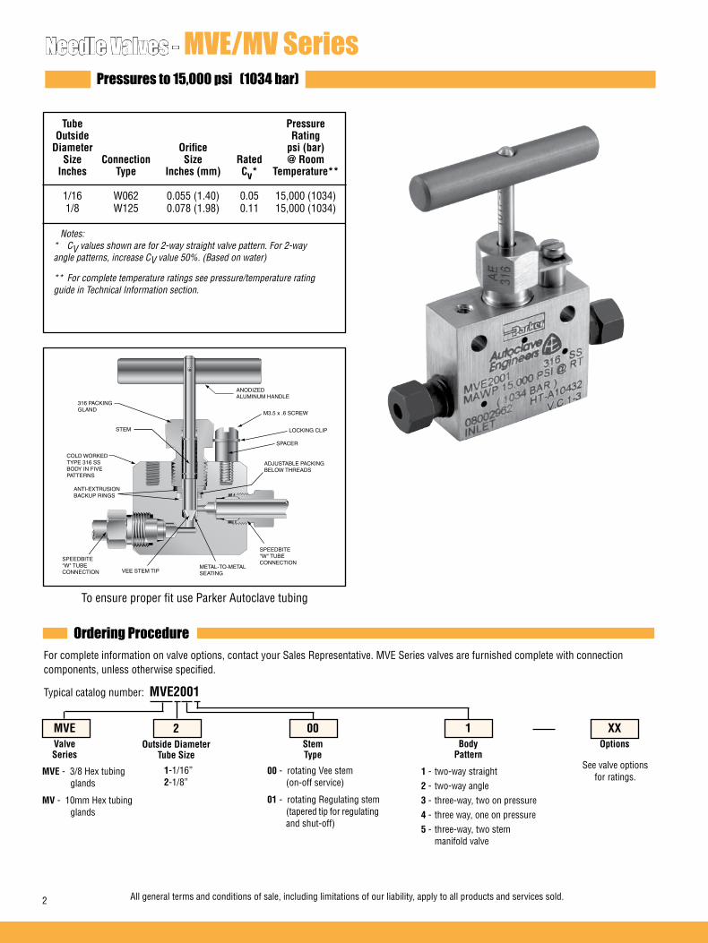
Needle Valves - MVE/MV SeriesPressures to 15,000 psi (1034 bar)
Tube Pressure Outside Rating Diameter Orifice psi (bar) Size Connection Size Rated @ Room Inches Type Inches (mm) Cv* Temperature** 1/16 W062 0.055 (1.40) 0.05 15,000 (1034) 1/8 W125 0.078 (1.98) 0.11 15,000 (1034) Notes:
* CV values shown are for 2-way straight valve pattern. For 2-way angle patterns, increase CV value 50%. (Based on water)
** For complete temperature ratings see pressure/temperature rating guide in Technical Information section.
To ensure proper fit use Parker Autoclave tubing
Ordering ProcedureFor complete information on valve options, contact your Sales Representative. MVE Series valves are furnished complete with connection components, unless otherwise specified.
Typical catalog number: MVE2001
1-1/16”2-1/8”
00 - rotating Vee stem (on-off service)
01 - rotating Regulating stem (tapered tip for regulating and shut-off)
1 - two-way straight2 - two-way angle3 - three-way, two on pressure4 - three way, one on pressure5 - three-way, two stem manifold valve
See valve options for ratings.
XXOptions
1Body
Pattern
00StemType
2Outside Diameter
Tube Size
MVEValveSeries
MVE - 3/8 Hex tubing glands
MV - 10mm Hex tubing glands
ANODIZEDALUMINUM HANDLE
STEM
ADJUSTABLE PACKING BELOW THREADS
COLD WORKED TYPE 316 SS BODY IN FIVE PATTERNS
316 PACKING GLAND
ANTI-EXTRUSIONBACKUP RINGS
VEE STEM TIPMETAL-TO-METAL SEATING
M3.5 x .6 SCREW
SPEEDBITE"W" TUBE CONNECTION
LOCKING CLIP
SPACER
SPEEDBITE"W" TUBE CONNECTION
All general terms and conditions of sale, including limitations of our liability, apply to all products and services sold.2

2-Way Angle
2-Way Straight
Valve Options Valve MaintenanceExtreme Temperatures Standard Parker Autoclave Engineers valves with PTFE packing may be operated to 450°F (232°C). High temperature packing is available for service from 0°F (-17.8°C) to 600°F (316°C) by adding the fol-lowing suffixes to catalog order number.=TG standard valve with PTFE glass packing to 600°F (316°C).
=Parker Autoclave Engineers does not recommend compression sleeve connections below 0°F (-17.8°C) or above 650°F (343°C). For additional valve options, contact your Sales Representative.
Refer to the Tools, Installation, Operation and Maintenance section for proper maintenance procedures.
G - Packing gland mounting hole drill size * H Dimension is with stem in closed position. For prompt service, Parker AutoclaveG1 - Bracket mounting hole size All dimensions for reference only and subject to change. Engineers stocks select products. Panel mounting screws are M3.5 x .7 thd. Consult factory.Tube glands are 3/8” hex on standard MVE modelsTube glands are 10mm hex on MV models.
Block Catalog Stem Diameter Orifice Thick- Valve Number Type Tube Diameter A B C D D1 E F G G1 H* M N ness Pattern
Dimensions - inches (mm)
MVE1001 VEE MV1001 VEE MVE2001 VEE MV2001 VEE
1/16 0.055 1.38 0.69 0.45 0.81 0.56 1.13 1.75 0.56 0.16 2.38 0.45 0.20 0.56 (1.57) (1.40) (34.93) (17.45) (11.43) (20.65) (14.30) (28.58) (44.45) (14.27) (4.04) (60.38) (11.49) (5.16) (14.27) 1/8 0.078 1.38 0.69 0.45 0.81 0.56 1.13 1.75 0.56 0.16 2.38 0.45 0.20 0.56 (3.18) (1.98) (34.93) (17.45) (11.43) (20.65) (14.30) (28.58) (44.45) (14.27) (4.04) (60.38) (11.49) (5.16) (14.27)
1/16 0.055 1.38 0.69 0.45 0.56 1.38 1.75 0.56 0.16 2.63 0.45 0.20 0.56 (1.57) (1.40) (34.93) (17.45) (11.43) (14.30) (34.93) (44.45) (14.27) (4.04) (66.75) (11.49) (5.16) (14.27) 1/8 0.078 1.38 0.69 0.45 0.56 1.38 1.75 0.56 0.16 2.38 0.45 0.20 0.56 (3.18) (1.98) (34.93) (17.45) (11.43) (14.30) (34.93) (44.45) (14.27) (4.04) (60.38) (11.49) (5.16) (14.27)
3-Way / 2 on Pressure 1/16 0.055 1.38 0.69 0.45 0.81 0.56 1.44 1.75 0.56 0.16 2.69 0.45 0.20 0.56 (1.57) (1.40) (34.93) (17.45) (11.43) (20.65) (14.30) (36.50) (44.45) (14.27) (4.04) (68.30) (11.49) (5.16) (14.27) 1/8 0.078 1.38 0.69 0.45 0.81 0.56 1.44 1.75 0.56 0.16 2.69 0.45 0.20 0.56 (3.18) (1.98) (34.93) (17.45) (11.43) (20.65) (14.30) (36.50) (44.45) (14.27) (4.04) (68.30) (11.49) (5.16) (14.27)
Outside
MVE1002 VEE MV1002 VEE MVE2002 VEE MV2002 VEE
MVE1003 VEE MV1003 VEE MVE2003 VEE MV2003 VEE
H N
F
G1G
DE
AB
C
D1
M M
2-Way Straight
Figure 1
H N
F
G1G
D
E
A
C
M M
B
2-Way Angle 3-Way / 2 on Pressure
Figure 3Figure 2
See Figure 1
See Figure 2
See Figure 3
All general terms and conditions of sale, including limitations of our liability, apply to all products and services sold. 3
H N
F
G1G
D
E
M M
C
D
AB

3-Way / 2-Stem Manifold
3-Way / 1 on Pressure
G - Packing gland mounting hole drill size * H Dimension is with stem in closed position. For prompt service, ParkerG1 - Bracket mounting hole size All dimensions for reference only and subject to change. Autoclave stocks select products. Panel mounting screws are M3.5 x .7 thd. Consult factory.Tube glands are 3/8 hex on standard MVE models Tube glands are 10mm hex on MV models
MVE1005 VEE MV1005 VEE MVE2005 VEE MV2005 VEE
1/16 0.055 1.38 0.69 0.45 0.81 0.56 1.63 1.75 0.56 0.16 4.11 0.45 0.20 0.56 (1.57) (1.40) (34.93) (17.45) (11.43) (20.65) (14.30) (41.28) (44.45) (14.27) (4.04) (104.44) (11.49) (5.16) (14.27) 1/8 0.078 1.38 0.69 0.45 0.81 0.56 1.63 1.75 0.56 0.16 4.11 0.45 0.20 0.56 (3.18) (1.98) (34.93) (17.45) (11.43) (20.65) (14.30) (41.28) (44.45) (14.27) (4.04) (104.44) (11.49) (5.16) (14.27)
MVE1004 VEE MV1004 VEE
MVE2004 VEE MV2004 VEE
1/16 0.055 1.38 0.69 0.45 0.56 0.56 1.44 1.75 0.56 0.16 2.69 0.45 0.20 0.56 (1.57) (1.40) (34.93) (17.45) (11.43) (14.22) (14.30) (36.50) (44.45) (14.27) (4.04) (68.30) (11.49) (5.16) (14.27) 1/8 0.078 1.38 0.69 0.45 0.56 0.56 1.44 1.75 0.56 0.16 2.69 0.45 0.20 0.56 (3.18) (1.98) (34.93) (17.45) (11.43) (14.22) (14.30) (36.50) (44.45) (14.27) (4.04) (68.30) (11.49) (5.16) (14.27)
H N
F
G1G
DE
M M
D
C
AB
3-Way / 1 on Pressure
Figure 4
H
N
F
G1G
D
E
D
D1
A
M M
B
3-Way / 2-Stem Manifold
Figure 5
See Figure 4
See Figure 5
Block Catalog Stem Diameter Orifice Thick- Valve Number Type Tube Diameter A B C D D1 E F G G1 H* M N ness Pattern
Dimensions - inches (mm)Outside
02-0114SE January2013© 2013 Parker Hannifin Corporation | Autoclave Engineers is a registered trademark of the Parker Hannifin Corporation
Parker Hannifin Manufacturing Ltd. Instrumentation Products Division, Europe Industrial Estate WhitemillWexford, Republic of IrelandPH: 353 53 914 1566FAX: 353 53 914 1582
Instrumentation Products DivisionAutoclave Engineers Operation8325 Hessinger DriveErie, Pennsylvania 16509-4679 USAPH: 814-860-5700 FAX: 814-860-5811www.autoclave.com
WARNINGFAILURE, IMPROPER SELECTION OR IMPROPER USE OF THE PRODUCTS AND/OR SYSTEMS DESCRIBED HEREIN OR RELATED ITEMS CAN CAUSE DEATH, PERSONAL INJURY AND PROPERTY DAMAGE.This document and other information from Parker Hannifin Corporation, its subsidiaries and authorized distributors provide product and/or system options for further investiga-tion by users having technical expertise. It is important that you analyze all aspects of your application and review the information concerning the product or system in the current product catalog. Due to the variety of operating conditions and applications for these products or systems, the user, through its own analysis and testing, is solely responsible for making the final selection of the products and systems and assuring that all performance, safety and warning requirements of the application are met. The products described herein, including without limitation, product features, specifications, designs, availability and pricing, are subject to change by Parker Hannifin Corporation and its subsidiaries at any time without notice.
Offer of SaleThe items described in this document are available for sale by Parker Hannifin Corporation, its subsidiaries or its authorized distributors. Any sale contract entered by Parker will begoverned by the provisions stated in Parker's standard terms and conditions of sale (copy available upon request).
ISO-9001 Certified
Caution! Do not mix or interchange parts or tubing with those of other manufacturers. Doing so is unsafe and will void warranty.
Caution! Parker Autoclave Engineers Valves, Fittings and Tools are not designed to work with common commercial instrument tubing and will only work with tubing built to Parker Autoclave Engineers AES Specifications. Failure to do so will void warranty.

All general terms and conditions of sale, including limitations of our liability, apply to all products and services sold. 1
Needle Valves - Bottle Valve SeriesLow Pressure
Needle Valves
Pressures to 15,000 psi (1034 bar)
Bottle Valve SeriesLow Pressure
Since 1945 Parker Autoclave Engineers has designed and built premium quality valves, fittings and tubing. Parker Autoclave Engineers has long been established as the world leader in high-pres-sure fluid handling components for the chemical/petrochemical, research, and oil and gas industries. Bottle valves are used on sample bottles and cylin-ders for remote sampling in the oil industry.
Bottle Valve Features:
• BTV Series valve design provides male inlet connections from 1/8" to 1/2" NPT.
• Outlet connections in NPT or tube to 1/4".
• Rising stem/barstock body design.
• Non-rotating stem prevents stem/seat galling.
• Metal-to-metal seating achieves bubble-tight shut- off, longer stem/seat life in abrasive flow, greater durability for repeated on/off cycles and excellent corrosion resistance.
• PTFE encapsulated packing provides dependable stem and body sealing.
• Stem sleeve and packing gland materials have been selected to achieve extended thread cycle life and reduced handle torque.
• Available with Vee stem tips.
• Available in five body patterns.
Parker Autoclave Engineers valves are comple-mented by a complete line of low pressure fittings, tubing, check valves and line filters. The Bottle Valve Series use Parker Autoclave Engineers' SpeedBite connection. This single-ferrule compression sleeve-connection delivers fast, easy make-up and reliable bubble-tight performance in liquid or gas service.
www.autoclave.com

All general terms and conditions of sale, including limitations of our liability, apply to all products and services sold.2
Valve Options Valve MaintenanceStandard Parker Autoclave valves with PTFE packing may be operated to 450°F (232°C).R regulating stem Parker Autoclave Engineers does not recommend compression sleeve con-nections below 0°F (-17.8°C) or above 650°F(343°C). For additional valve options, contact your Sales Representative.
Repair Kits: add “R” to the front of valve catalog number for proper repair kit. (Example: RBTV4F2L1)
Valve Bodies: Valve bodies are available. Order using the eight (8) digit part number found on the valve drawing or contact your Sales Representative for information.Consult your Parker Autoclave Engineers representative for pricing on repair kits and valve bodies. Refer to the Tools, Installation, Operation and Mainte-nance section for proper maintenance procedures.
Valve Series - BTV SeriesPressures to 15,000 psi (1034 bar)
To ensure proper fit use Autoclave tubing
Ordering ProcedureFor complete information on available stem types, optional connections and additional valve options, see Needle Valve Options section or contact your Sales Representative. BTV Series valves are furnished complete with connection components, unless otherwise specified.
Typical catalog number: BTV4S4P1
2-1/8”4-1/4”6-3/8”8-1/2”
F - FrontS - Side B - Bottom
PFemale
Connection Type
4Female
Port Sizes
SMale NPT Position
4Male NPT
BTV Valve Series
*Note: 1 inlet is NPT male 2 inlets are NPT male and 1 female connection
2-1/8”4-1/4”6-3/8”8-1/2”
P - NPTL - Low Pressure
1 - Straight2 - Angle 3 - 3 Way 2 on Pressure *24 - 3 Way 1 on Pressure *1
1Body
Pattern
PACKING GLAND
COLD WORKED TYPE 316SS VALVE BODY
NON-ROTATINGSTEM
ADJUSTABLE PACKINGBELOW THREADS
LOCKINGDEVICE
METAL-TO-METAL SEATING
BOTTOMWASHER
ALUMINUM HANDLE
XXOptions
R - Regulating Stem

All general terms and conditions of sale, including limitations of our liability, apply to all products and services sold. 3
3-Way/2 on Pressure
3-Way/1 on Pressure
2-Way Angle
2-Way Straight BTV4S4P1 VEE Side Inlet
BTV4F2L1 VEE Front Inlet
1/4 0.094 2.00 1.31 0.69 0.82 0.82 1.28 1.50 0.61 3.41 0.56 0.75
(6.35) (2.39) (50.80) (33.27) (17.53) (20.83) (20.83) (32.51) (38.10) (15.49) (86.61) (14.22) (19.05)
1/8 0.094 1.50 0.75 0.63 0.81 0.88 1.38 1.50 0.61 3.49 0.56 0.63
(3.18) (2.39) (38.10) (19.05) (15.88) (20.57) (22.35) (35.05) (38.10) (15.49) (88.65) (14.22) (16.00)
G - Packing gland mounting hole drill size * H Dimension is with stem in closed position. For prompt service, Parker Autoclave Engineers stocks select products. Consult factory.All dimensions for reference only and subject to change.
2-Way Straight 2-Way Angle2-Way Straight
Figure 3Figure 2Figure 1
See Figure 1
Catalog Stem Pipe/ Orifice Number Type Tube Diameter A B C D D1 D2 E F G H M
Dimensions - inches (mm)Valve
PatternBlock Thickness
BTV4B2L2 VEE Bottom Inlet
BTV4B4P2 VEE Bottom Inlet
1/8 0.094 2.00 1.00 0.81 1.19 1.63 1.50 0.75 4.75 0.62 0.75
(3.18) (2.39) (50.80) (25.40) (20.57) (30.23) (41.40) (38.10) (19.05) (120.65) (15.75) (19.05)
1/4 0.203 1.50 1.00 1.25 1.19 1.63 3.00 0.75 5.30 0.62 0.75
(6.35) (5.16) (38.10) (25.40) (31.75) (30.23) (41.40) (76.20) (19.05) (134.62) (15.75) (19.05)
See Figure 3
See Figure 2
See Figure 3
BTV4F2L3 VEE Front Inlet
1/8 0.094 1.50 0.75 0.63 0.81 1.06 0.88 1.38 1.50 0.75 3.49 0.50 0.75
(3.18) (2.39) (38.10) (19.05) (15.88) (20.57) (26.92) (22.35) (34.93) (38.10) (19.05) (88.65) (12.70) (19.05)
See Figure 4
BTV4F2L4 VEE Front Inlet
1/8 0.094 1.50 .75 0.63 0.81 0.81 0.88 1.38 1.50 0.75 3.49 0.50 0.75
(3.18) (2.39) (38.10) (19.05) (15.88) (20.57) (20.57) (22.35) (34.93) (38.10) (19.05) (86.66) (12.70) (19.05)
See Figure 5
Catalog Stem Pipe/ Orifice Number Type Tube Diameter A B C D D1 D2 E F G H M
Dimensions - inches (mm)Valve
PatternBlock Thickness
Figure 4 Figure 5
3-Way / 2 on Pressure 3-Way / 1 on Pressure
H
F
G
D1DE
M
ABC
E
F
G
D
HM
AB
D2
C
E
F
G
DH
M
AB
C
E
F
G
D
HM
AB
D1 D2
C
E
F
G
D
HM
AB
D1 D2
C

02-1248SE January 2013© 2013 Parker Hannifin Corporation | Autoclave Engineers is a registered trademark of the Parker Hannifin Corporation
Parker Hannifin Manufacturing Ltd. Instrumentation Products Division, Europe Industrial Estate WhitemillWexford, Republic of IrelandPH: 353 53 914 1566FAX: 353 53 914 1582
Instrumentation Products DivisionAutoclave Engineers Operation8325 Hessinger DriveErie, Pennsylvania 16509-4679 USAPH: 814-860-5700 FAX: 814-860-5811www.autoclave.com
WARNING
FAILURE, IMPROPER SELECTION OR IMPROPER USE OF THE PRODUCTS AND/OR SYSTEMS DESCRIBED HEREIN OR RELATED ITEMS CAN CAUSE DEATH, PERSONAL INJURY AND PROPERTY DAMAGE.This document and other information from Parker Hannifin Corporation, its subsidiaries and authorized distributors provide product and/or system options for further investigation by users having technical expertise. It is important that you analyze all aspects of your application and review the information concerning the product or system in the current product catalog. Due to the variety of operating conditions and applications for these products or systems, the user, through its own analysis and testing, is solely responsible for making the final selection of the products and systems and assuring that all performance, safety and warning requirements of the application are met. The products described herein, including without limitation, product features, specifications, designs, availability and pricing, are subject to change by Parker Hannifin Corporation and its subsidiaries at any time without notice.
Offer of Sale
The items described in this document are available for sale by Parker Hannifin Corporation, its subsidiaries or its authorized distributors. Any sale contract entered by Parker will be governed by the provisions stated in Parker's standard terms and conditions of sale (copy available upon request).
ISO-9001 Certified
Caution! Do not mix or interchange parts or tubing with those of other manufacturers. Doing so is unsafe and will void warranty.
Caution! Parker Autoclave Engineers Valves, Fittings and Tools are not designed to work with common commercial instrument tubing and will only work with tubing built to Parker Autoclave Engineers AES Specifications. Failure to do so will void warranty.

MicroMetering Valve Features:
• Barrel and Thimble design permits repeatable settings.• Barrel divisions every 0.025”• 25 Thimble divisions, each representing 0.001” stem travel• One revolution = 0.025” stem travel• Cold-worked type 316 stainless steel body with stainless steel packing gland. Stem
and seat are cold-worked type 316 stainless steel.• Packing below stem threads is PTFE for the 10VRMM and 30VRMM valves and nylon- leather for the 60VRMM. For packing options, see Technical Information Section.• SpeedBite “W” connections are used on the 10VRMM and Parker AE High Pressure
coned-and-threaded connections on 30VRMM and 60VRMM.Parker Autoclave Engineers valves are complemented by a complete line of fittings, tubing, check valves andline filters.
MicroMetering valves are designed for applications where more precise control of small flows is required than is possible with a standard regulating stem. Barrel and Thimble micrometer design permits settings to be repeated.Metering is effected by a finely tapered stem acting in a precisely mated replaceable seat. Very fine stem position is achieved utilizing a 40 TPI thread. The Barrel and Thimble are set for proper metering at the factory.These valves are designed for metering only and cannot be used as a shutoff valve. Minimum flow is factory set and occurs at “0” position. DO NOT OPERATE THE VALVE BELOW THE ZERO POSITION OR DAMAGE WILL RESULT. When shutoff action is re-quired, a correlated shutoff valve from Parker AE series 10V, 30VM or 60VM should be installed in series with the MicroMetering valve.
Needle Valves
Pressures to 60,000 psi (4137 bar)
VRMM SeriesMicroMetering
Needle Valves - VRMM SeriesMicroMeteringwww.autoclave.com

Needle Valves - MicroMeteringPressures to 60,000 psi (4137 bar)
Tube Pressure Outside Rating Diameter Orifice psi (bar) Size Connection Size Rated @ Room Inches Type Inches (mm) Cv Temperature** 10VRMM 1/8 W125 0.062 (1.57) 0.004 15,000 (1034) 30VRMM 1/4 F250C 0.062 (1.57) 0.004 30,000 (2069) 60VRMM 1/4 F250C 0.062 (1.57) 0.004 60,000 (4137) 60VRMM 3/8 F375C 0.062 (1.57) 0.004 60,000 (4137) .
To ensure proper fit use Parker Autoclave Engineers tubing
Ordering ProcedureFor complete information on available stem types, optional connections and additional valve options, see Needle Valve Options section or contact your Sales Representative. VRMM Series valves are furnished complete with connection components, unless otherwise specified.
Typical catalog number: 60VRMM4812
Flow Coefficient (Cv)
Cv
Ste
m T
rave
l: In
ches
(m
m)
0.001 0.002 0.003 0.004
0.175
0.150
0.125
0.100
0.075
0.050
0.025
0
(4.45)
(3.81)
(3.18)
(2.54)
(1.90)
(1.27)
(.64)
LOCKING DEVICEPACKING GLAND
*NON-ROTATINGSTEM
ADJUSTABLEPACKING BELOW THREADS
STAINLESS STEEL BODY REPLACEABLE SEAT
POWDER COATEDSTAINLESS STEEL
HANDLE
2-1/8”4-1/4”6-3/8”
81 - Rotating regulating one piece stem with replaceable seat.
2 - two-way angle For extreme temperature and other
options, see Valve Options.
XXOptions
2Body
Pattern
81Stem/Seat
Type
4Outside Diameter
Tube Size
60VRMMValveSeries
10VRMM 30VRMM 60VRMM
2 All general terms and conditions of sale, including limitations of our liability, apply to all products and services sold.
NOTE:Ordering procedure for information only. Models available are shown in tables on next page.
Note:
** For complete temperature ratings see pressure/temperature rating guide in Technical Information section
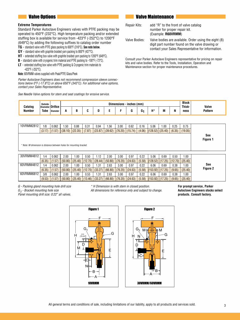
Block Catalog Diameter Orifice Thick- Valve Number Tube Diameter A B C D E F G G1 H* M N ness Pattern
Valve Options Valve MaintenanceExtreme Temperatures Standard Parker Autoclave Engineers valves with PTFE packing may be operated to 450°F (232°C). High temperature packing and/or extended stuffing box is available for service from -423°F (-252°C) to 1200°F (649°C) by adding the following suffixes to catalog order numberTG - standard valve with PTFE glass packing to 600°F (316°C). See note below.GY - standard valve with graphite braided yarn packing to 800°F (427°C).HT - extended stuffing box valve with graphite braided yarn packing to 1200°F (649°C).B - standard valve with cryogenic trim material and PTFE packing to -100°F (-73°C).LT - extended stuffing box valve with PTFE packing & Cryogenic trim materials to -423°F (-252°C).Note: 60VRMM valves supplied with Peak/PTFE Glass/Peek
Parker Autoclave Engineers does not recommend compression sleeve connec-tions below 0°F (-17.8°C) or above 650°F (343°C). For additional valve options, contact your Sales Representative.
See Needle Valve options for stem and seat coatings for erosive service.
Repair Kits: add “R” to the front of valve catalog number for proper repair kit. (Example: R60VRMM)
Valve Bodies: Valve bodies are available. Order using the eight (8) digit part number found on the valve drawing or contact your Sales Representative for information. Consult your Parker Autoclave Engineers representative for pricing on repair kits and valve bodies. Refer to the Tools, Installation, Operation and Maintenance section for proper maintenance procedures.
G - Packing gland mounting hole drill size * H Dimension is with stem in closed position. For prompt service, Parker G1 - Bracket mounting hole size All dimensions for reference only and subject to change. Autoclave Engineers stocks select Panel mounting drill size: 0:22” all valves. products. Consult factory.
Dimensions - inches (mm)
10VRMM2812 1/8 0.062 1.50 0.88 0.31 0.94 1.56 3.00 0.62 0.16 5.06 1.00 0.25 0.75 (3.17) (1.57) (38.10) (22.35) (7.87) (23.87) (39.62) (76.20) (15.74) (4.06) (128.52) (25.40) (6.35) (19.05)
Outside
30VRMM4812 1/4 0.062 2.00 1.00 0.50 1.12 2.00 3.00 0.97 0.22 5.06 0.69 0.50 1.00 (6.35) (1.57) (50.80) (25.40) (12.70) (28.44) (50.80) (76.20) (24.63) (5.58) (128.52) (17.25) (12.70) (25.40) 1/4 0.062 2.00 1.00 0.50 1.31 2.63 3.00 0.97 0.22 6.06 0.69 0.38 1.00 (6.35) (1.57) (50.80) (25.40) (12.70) (33.27) (66.80) (76.20) (24.63) (5.58) (153.92) (17.25) (9.65) (25.40) 3/8 0.062 2.00 1.00 0.53 1.31 2.63 3.00 0.97 0.22 6.06 0.69 0.38 1.00 (9.53) (1.57) (50.80) (25.40) (13.46) (33.27) (66.80) (76.20) (24.63) (5.58) (153.92) (17.25) (9.65) (25.40)
60VRMM4812
60VRMM6812
* Note: M dimension is distance between holes for mounting bracket.
10VRMM
Figure 1
See Figure 1
30VRMM/60VRMM
Figure 2
See Figure 2
All general terms and conditions of sale, including limitations of our liability, apply to all products and services sold. 3
H
N
F
G1G
DE
AB
C
M
.312(79.24) H N
F
G1
G
D
E
M M
AB
C

02-0115SE January2013© 2013 Parker Hannifin Corporation | Autoclave Engineers is a registered trademark of the Parker Hannifin Corporation
Parker Hannifin Manufacturing Ltd. Instrumentation Products Division, Europe Industrial Estate WhitemillWexford, Republic of IrelandPH: 353 53 914 1566FAX: 353 53 914 1582
Instrumentation Products DivisionAutoclave Engineers Operation8325 Hessinger DriveErie, Pennsylvania 16509-4679 USAPH: 814-860-5700 FAX: 814-860-5811www.autoclave.com
WARNINGFAILURE, IMPROPER SELECTION OR IMPROPER USE OF THE PRODUCTS AND/OR SYSTEMS DESCRIBED HEREIN OR RELATED ITEMS CAN CAUSE DEATH, PERSONAL INJURY AND PROPERTY DAMAGE.This document and other information from Parker Hannifin Corporation, its subsidiaries and authorized distributors provide product and/or system options for further investiga-tion by users having technical expertise. It is important that you analyze all aspects of your application and review the information concerning the product or system in the current product catalog. Due to the variety of operating conditions and applications for these products or systems, the user, through its own analysis and testing, is solely responsible for making the final selection of the products and systems and assuring that all performance, safety and warning requirements of the application are met. The products described herein, including without limitation, product features, specifications, designs, availability and pricing, are subject to change by Parker Hannifin Corporation and its subsidiaries at any time without notice.
Offer of SaleThe items described in this document are available for sale by Parker Hannifin Corporation, its subsidiaries or its authorized distributors. Any sale contract entered by Parker will begoverned by the provisions stated in Parker's standard terms and conditions of sale (copy available upon request).
ISO-9001 Certified
Caution! Do not mix or interchange parts or tubing with those of other manufacturers. Doing so is unsafe and will void warranty.
Caution! Parker Autoclave Engineers Valves, Fittings and Tools are not designed to work with common commercial instrument tubing and will only work with tubing built to Parker Autoclave Engineers AES Specifications. Failure to do so will void warranty.
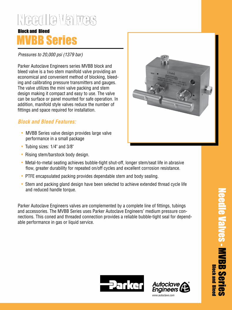
Parker Autoclave Engineers series MVBB block and bleed valve is a two stem manifold valve providing an economical and convenient method of blocking, bleed-ing and calibrating pressure transmitters and gauges. The valve utilizes the mini valve packing and stem design making it compact and easy to use. The valve can be surface or panel mounted for safe operation. In addition, manifold style valves reduce the number of fittings and space required for installation.
Block and Bleed Features:
• MVBB Series valve design provides large valve performance in a small package
• Tubing sizes: 1/4" and 3/8"
• Rising stem/barstock body design.
• Metal-to-metal seating achieves bubble-tight shut-off, longer stem/seat life in abrasive flow, greater durability for repeated on/off cycles and excellent corrosion resistance.
• PTFE encapsulated packing provides dependable stem and body sealing.
• Stem and packing gland design have been selected to achieve extended thread cycle life and reduced handle torque.
Parker Autoclave Engineers valves are complemented by a complete line of fittings, tubings and accessories. The MVBB Series uses Parker Autoclave Engineers’ medium pressure con-nections. This coned and threaded connection provides a reliable bubble-tight seal for depend-able performance in gas or liquid service.
Needle Valves
Pressures to 20,000 psi (1379 bar)
MVBB SeriesBlock and Bleed
Needle Valves - MVBB SeriesBlock and Bleed
www.autoclave.com
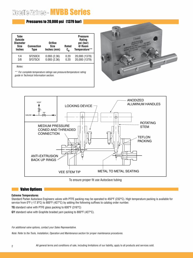
Valve Options
Needle Valves - MVBB SeriesPressures to 20,000 psi (1379 bar)
Tube Pressure Outside Rating Diameter Orifice psi (bar) Size Connection Size Rated @ Room Inches Type Inches (mm) Cv Temperature** 1/4 SF250CX 0.093 (2.36) 0.20 20,000 (1379) 3/8 SF375CX 0.093 (2.36) 0.20 20,000 (1379) Notes:
** For complete temperature ratings see pressure/temperature rating guide in Technical Information section.
To ensure proper fit use Autoclave tubing
Extreme Temperatures Standard Parker Autoclave Engineers valves with PTFE packing may be operated to 450°F (232°C). High temperature packing is available for service from 0°F (-17.8°C) to 800°F (427°C) by adding the following suffixes to catalog order number.
TG standard valve with PTFE glass packing to 600°F (316°C)
GY standard valve with Graphite braided yarn packing to 800°F (427°C).
For additional valve options, contact your Sales Representative.
Note: Refer to the Tools, Installation, Operation and Maintenance section for proper maintenance procedures.
TEFLONPACKING
ROTATINGSTEM
METAL TO METAL SEATINGVEE STEM TIP
ANODIZED ALUMINUM HANDLES
MEDIUM PRESSURECONED AND THREADEDCONNECTION
LOCKING DEVICE
ANTI-EXTRUSIONBACK UP RINGS
2 All general terms and conditions of sale, including limitations of our liability, apply to all products and services sold.
GAUGE
VENT
IN
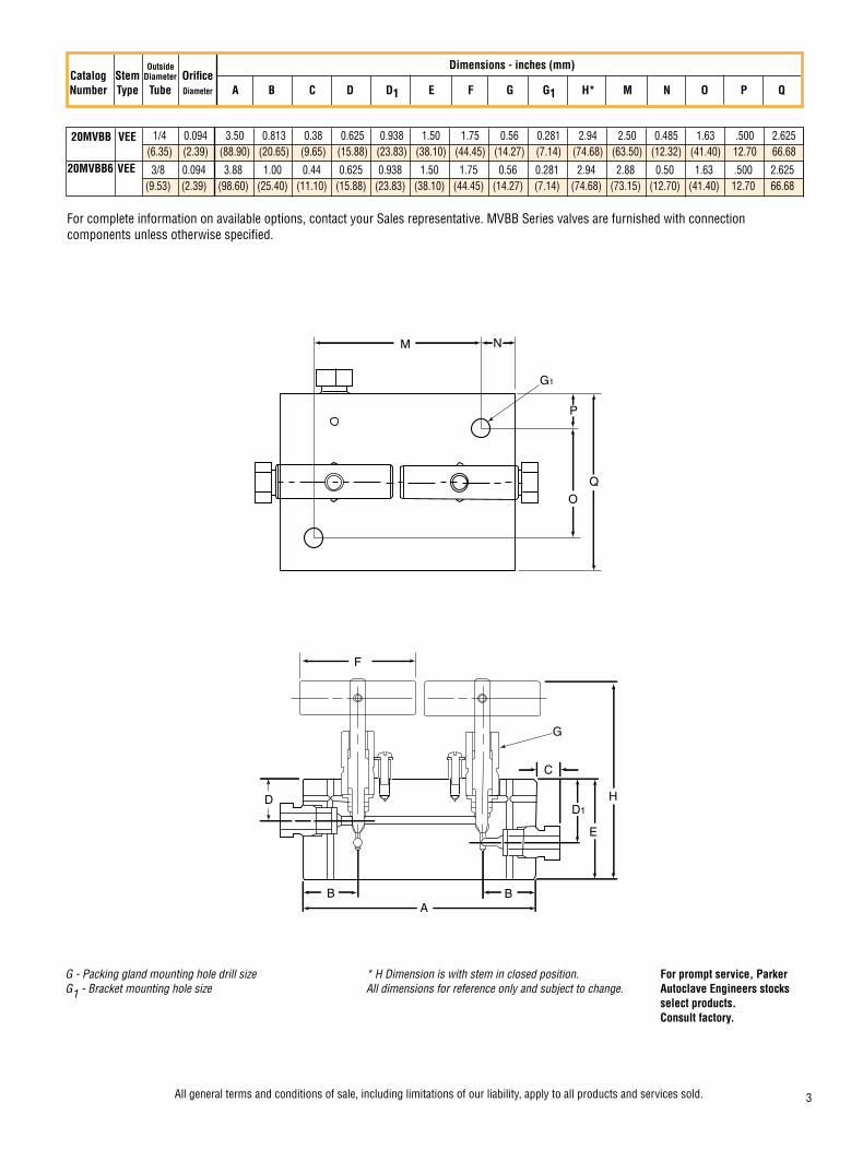
G - Packing gland mounting hole drill size * H Dimension is with stem in closed position. For prompt service, Parker G1 - Bracket mounting hole size All dimensions for reference only and subject to change. Autoclave Engineers stocks select products. Consult factory.
Catalog Stem Diameter Orifice Number Type Tube Diameter A B C D D1 E F G G1 H* M N O P Q
Dimensions - inches (mm)
20MVBB VEE
1/4 0.094 3.50 0.813 0.38 0.625 0.938 1.50 1.75 0.56 0.281 2.94 2.50 0.485 1.63 .500 2.625 (6.35) (2.39) (88.90) (20.65) (9.65) (15.88) (23.83) (38.10) (44.45) (14.27) (7.14) (74.68) (63.50) (12.32) (41.40) 12.70 66.68
Outside
F
D
B BA
D1
C
E
H
G
M N
G1
O
P
Q
For complete information on available options, contact your Sales representative. MVBB Series valves are furnished with connection components unless otherwise specified.
All general terms and conditions of sale, including limitations of our liability, apply to all products and services sold. 3
3/8 0.094 3.88 1.00 0.44 0.625 0.938 1.50 1.75 0.56 0.281 2.94 2.88 0.50 1.63 .500 2.625 (9.53) (2.39) (98.60) (25.40) (11.10) (15.88) (23.83) (38.10) (44.45) (14.27) (7.14) (74.68) (73.15) (12.70) (41.40) 12.70 66.68
20MVBB6 VEE

02-0116SE January2013© 2013 Parker Hannifin Corporation | Autoclave Engineers is a registered trademark of the Parker Hannifin Corporation
Parker Hannifin Manufacturing Ltd. Instrumentation Products Division, Europe Industrial Estate WhitemillWexford, Republic of IrelandPH: 353 53 914 1566FAX: 353 53 914 1582
Instrumentation Products DivisionAutoclave Engineers Operation8325 Hessinger DriveErie, Pennsylvania 16509-4679 USAPH: 814-860-5700 FAX: 814-860-5811www.autoclave.com
WARNINGFAILURE, IMPROPER SELECTION OR IMPROPER USE OF THE PRODUCTS AND/OR SYSTEMS DESCRIBED HEREIN OR RELATED ITEMS CAN CAUSE DEATH, PERSONAL INJURY AND PROPERTY DAMAGE.This document and other information from Parker Hannifin Corporation, its subsidiaries and authorized distributors provide product and/or system options for further investiga-tion by users having technical expertise. It is important that you analyze all aspects of your application and review the information concerning the product or system in the current product catalog. Due to the variety of operating conditions and applications for these products or systems, the user, through its own analysis and testing, is solely responsible for making the final selection of the products and systems and assuring that all performance, safety and warning requirements of the application are met. The products described herein, including without limitation, product features, specifications, designs, availability and pricing, are subject to change by Parker Hannifin Corporation and its subsidiaries at any time without notice.
Offer of SaleThe items described in this document are available for sale by Parker Hannifin Corporation, its subsidiaries or its authorized distributors. Any sale contract entered by Parker will begoverned by the provisions stated in Parker's standard terms and conditions of sale (copy available upon request).
ISO-9001 Certified
Caution! Do not mix or interchange parts or tubing with those of other manufacturers. Doing so is unsafe and will void warranty.
Caution! Parker Autoclave Engineers Valves, Fittings and Tools are not designed to work with common commercial instrument tubing and will only work with tubing built to Parker Autoclave Engineers AES Specifications. Failure to do so will void warranty.

Parker Autoclave Engineers series DBNV double block and bleed valve is a three system manifold valve provid-ing an economical and convenient method of blocking and bleeding in applications such as pressure monitor-ing and test, chemical injection and drain line isolation. The valve utilizes our standard valve packing and stem design to make it compact and easy to use. Manifold style valves reduce the number of fittings and space required for installation.
Block and Bleed Features:
• 20DBNV Series valve design provides large valve performance in a small package.
• Tubing sizes: 1/4" to 1".
• Rising stem/barstock body design.
• Metal-to-metal seating achieves bubble-tight shut-off, longer stem/seat life in abrasive flow, greater durability for repeated on/off cycles and excellent corrosion resistance.
• PTFE encapsulated packing provides dependable stem and body sealing.
• Stem and packing gland design have been selected to achieve extended thread cycle life and reduced handle torque.
• Temperatures from -100°F (-73°C) to 600°F (316°C)
Parker Autoclave Engineers' valves are complemented by a complete line of fittings, tubings and accessories. The 20DBNV Series uses Parker Autoclave Engineers' pressure connections. This coned and threaded connection provides a reliable bubble-tight seal for dependable performance in gas or liquid service.
Needle Valves
Pressures to 20,000 psi (1379 bar)
20DBNV SeriesDouble Block and Bleed
Needle Valves - 20DBNV SeriesDouble Block and Bleed
www.autoclave.com

Valve Options
Needle Valves - 20DBNV SeriesPressures to 20,000 psi (1379 bar)
Tube Pressure Outside Rating Diameter Orifice psi (bar) Size Connection Size Rated @ Room Inches Type Inches (mm) Cv Temperature** 1/4 SF250CX 0.093 (2.36) 0.10 20,000 (1379) 3/8 SF375CX 0.093 (2.36) 0.27 20,000 (1379) 9/16 F562C 0.093 (2.36) 0.27 20,000 (1379) Notes:
** For complete temperature ratings see pressure/temperature rating guide in Technical Information section.
To ensure proper fit use Parker Autoclave Engineers tubing
Extreme Temperatures Standard Parker Autoclave Engineers' valves with PTFE packing may be operated to 450°F (232°C). High temperature packing is available for service from 0°F (-17.8°C) to 800°F (427°C) by adding the following suffixes to catalog order number.TG standard valve with PTFE glass packing to 600°F (316°C).
B standard valve with cryogenic trim material and PTFE packing to -100°F (-73°C).
For additional valve options, contact your Sales Representative.Note: Refer to the Tools, Installation, Operation and Maintenance section for proper maintenance procedures.
2 All general terms and conditions of sale, including limitations of our liability, apply to all products and services sold.
ALUMINUM BRONZE PACKING GLAND
COLD WORKED TYPE 316 SS BODY
NON-ROTATINGSTEM
ADJUSTABLEPACKINGBELOW THREADS
LOCKING DEVICE
HIGH PRESSURE CONED-AND-THREADED CONNECTIONS
VEE STEM TIPMETAL-TO-METAL SEATING
ANTI-EXTRUSIONBACK-UP RINGS
POWDER COATEDSTAINLESS STEELHANDLE
VENT CONNECTION
INLET
PLUGGED
OUTLET
VENT VALVE
BOTTOM VIEW
All general terms and conditions of sale, including limitations of our liability, apply to all products and services sold. 3
Connection Options
Catalog Tube Connection MAWP @ Vent Connection Vent Number Number Connection Room Temperature Number Connection
20DBNVM4M4 M4 SF250CX20 20,000 psi (1379 bar) M4 SF250CX20
20DBNVM6M4 M6 SF375CX20 20,000 psi (1379 bar) M4 SF250CX20
20DBNVH9M4 H9 F562C 20,000 psi (1379 bar) M4 SF250CX20
See needle valve options for complete information on available stem types, optional connections and additional valve options.For material options consult factory.
Consult your Parker Autoclave Engineers representative for pricing on repair kits. Refer to the Operation and Mainte-nance manual for proper maintenance procedures.
Valve Maintenance
MAWP: Maximum Allowable Working Pressure
Ordering Procedure
M4Vent ConnectionM4 - SF250CX20(see chart below)
M4Tube
Connection
20DBNVValveSeries
20DBNV DoubleBlock & BleedNeedle Valve
For complete information on available end connections, see end connections options below. 20DBNV valves are furnished complete with tube connections.
Typical catalog number: 20DBNV M4 M4 XXX
XXX
TG - PTFE Glass PackingB - Cryogenic Trim -100°F (-73°C)K - Anti-vibration Collet & Gland Assembly
Options
Valve Options
M4 - SF250CX20M6 - SF375CX20H9 - F562C(see chart below)

For complete information on available options, contact your Sales representative. 20DBNV Series valves are furnished with connection components unless otherwise specified.
G
D1
E
M
B
H
F
D
V
N
M
A
B
X
P
C
O
PLUGGEDINLET
OUTLETVENT
BOTTOM VIEW
VENT VALVE
G - Packing gland mounting hole drill size H Dimension is with stem in closed position. All dimensions for reference only and subject to change For prompt service, Parker Autoclave Engineers stocks select products. Consult factory.
02-9259BE January 2013© 2013 Parker Hannifin Corporation | Autoclave Engineers is a registered trademark of the Parker Hannifin Corporation
Parker Hannifin Manufacturing Ltd. Instrumentation Products Division, Europe Industrial Estate WhitemillWexford, Republic of IrelandPH: 353 53 914 1566FAX: 353 53 914 1582
Instrumentation Products DivisionAutoclave Engineers Operation8325 Hessinger DriveErie, Pennsylvania 16509-4679 USAPH: 814-860-5700 FAX: 814-860-5811www.autoclave.com
WARNING
FAILURE, IMPROPER SELECTION OR IMPROPER USE OF THE PRODUCTS AND/OR SYSTEMS DESCRIBED HEREIN OR RELATED ITEMS CAN CAUSE DEATH, PERSONAL INJURY AND PROPERTY DAMAGE.This document and other information from Parker Hannifin Corporation, its subsidiaries and authorized distributors provide product and/or system options for further investigation by users having technical expertise. It is important that you analyze all aspects of your application and review the information concerning the product or system in the current product catalog. Due to the variety of operating conditions and applications for these products or systems, the user, through its own analysis and testing, is solely responsible for making the final selection of the products and systems and assuring that all performance, safety and warning requirements of the application are met. The products described herein, including without limitation, product features, specifications, designs, availability and pricing, are subject to change by Parker Hannifin Corporation and its subsidiaries at any time without notice.
Offer of Sale
The items described in this document are available for sale by Parker Hannifin Corporation, its subsidiaries or its authorized distributors. Any sale contract entered by Parker will be governed by the provisions stated in Parker's standard terms and conditions of sale (copy available upon request).
CatalogNumber
StemType
Pipe Size
Orifice
Dia.
Dimensions - inches (mm)
A B C D D1 E F G H M N O P Q V X
20DBNVM4M4 VEE1/4 0.094 5.25 1.00 0.38 1.50 1.13 2.13 3.00 1.00 4.65 0.69 0.50 0.75 0.63 1.50 1.43 .50
(6.35) (2.39) (133.35) (25.40) (9.65) (38.10) (28.70) (54.10) (76.20) (25.40) (118.11) (17.53) (12.70) (19.05) (16.00) (38.10) (36.32) (12.70)
20DBNVM6M4 VEE3/8 0.094 5.25 1.00 0.44 1.50 1.13 2.13 3.00 1.00 4.65 0.69 0.50 0.75 0.63 1.50 1.43 .50
(9.53) (2.39) (133.35) (25.40) (11.18) (38.10) (28.70) (54.10) (76.20) (25.40) (118.11) (17.53) (12.70) (19.05) (16.00) (38.10) (36.32) (12.70)
20DBNVH9M4 VEE9/16 0.094 5.88 1.31 0.53 1.50 1.13 3.00 3.00 1.00 5.53 0.69 0.50 1.38 0.63 1.75 1.43 .75
(14.29) (2.39) (149.35) (33.27) (13.46) (38.10) (28.70) (76.20) (76.20) (25.40) (140.46) (17.53) (12.70) (35.05) (16.00) (44.45) (36.32) (19.05)
ISO-9001 Certified
Caution! Do not mix or interchange parts or tubing with those of other manufacturers. Doing so is unsafe and will void warranty.
Caution! Parker Autoclave Engineers Valves, Fittings and Tools are not designed to work with common commercial instrument tubing and will only work with tubing built to Parker Autoclave Engineers AES Specifications. Failure to do so will void warranty.

Tube Pressure Outside Rating Series Diameter Orifice psi (bar) Size Connection Size Rated @ Room Inches Type Inches (mm) Cv Temperature 20GV 3/8 F375C 0.125 (3.18) 0.23 20,000 (1379) 20GV 9/16 SF562CX 0.125 (3.18) 0.23 20,000 (1379) 30GV 9/16 F562C 0.125 (3.18) 0.33 30,000 (2068)
Bleed Valve 20BV 3/8 SM375CX 0.093 (2.36) - 20,000 (1379) 20BV 9/16 SM562CX 0.093 (2.36) - 20,000 (1379) 30BV 9/16 M562C 0.093 (2.36) - 30,000 (2068)*
Ordering Procedure
6-3/8”9-9/16”
00 - one piece VEE stem07- non-rotating VEE stem
8 - 4 ports, 1 inlet, 3 outlets
8Body
Pattern
07StemType
9Outside Diameter
Tube Size
30GVValveSeries
Needle Valves - Wellhead Gauge and Bleed ValvesPressures to 30,000 psi (2068 bar)
Notes: * Rating shown is in closed position. Rating @ 15,000 psi (1034 bar) in open position. Glands and collars included
Parker Autoclave Engineers’ Wellhead Gauge valves are designed for reliable shut-off service at a maximum work-ing pressure of 30,000 psi (2068 bar). The Wellhead Gauge and Bleed Valves are standard in 316 stainless steel material. Special materials available on request.
Applications: Wellhead Gauge Valve • Sample Lines • Instrument calibration
Bleed Valve • Pressure bleed
Gauge Valve Features: • One inlet, three outlet ports • Metal-to-metal bubble tight shut-off • Packing below stem threads • Two piece non-rotating stem on standard valves Bleed Valve Features: • One piece hex construction allows easy installation • Vent port tapped for plumbing to safe area • Tee handle for easy operation • Positive blow out prevention on stem • 1/8” NPT outlet connection
20GV30GV
Typical catalog number: 30GV9078
6-3/8”9-9/16”
00 - one piece VEE stem 2 -Angle
2Body
Pattern
00StemType
9Outside Diameter
Tube Size
30BVValveSeries
20BV30BV
Typical catalog number: 30BV9002Bleed Valve
Wellhead Gauge Valve

Valve A B C D E F G H J Pattern
Dimensions - inches (mm)
SF375CX 3/8 20,000 2.00 3.12 2.00 4.52 1.13 1.00 0.50 0.94 3.00 (1379) (50.80) (79.25) (50.80) (114.80) (28.58) (25.40) (12.70) (23.83) (76.20) SF562CX 9/16 20,000 2.00 3.88 2.75 4.54 1.31 1.38 0.66 0.94 3.00 (1379) (50.80) (98.55) (69.85) (115.31) (33.27) (34.93) (16.76) (23.83) (76.20) F562C 9/16 30,000 2.00 3.88 2.75 4.50 1.31 1.38 0.66 0.94 3.00 (2068) (50.80) (98.55) (69.85) (114.30) (33.27) (34.93) (16.76) (23.83) (76.20)
Catalog Number
Connection Size
Pressure Ratingpsi (bar)
ConnectionType
Figure 1 - Wellhead Gauge Valve
See Figure 1
20GV6078
20GV9078
Wellhead Gauge Valve
A B C D E
Dimensions - inches (mm)
SM375CX 3/8 20,000 3.23 2.42 1.12 1.38 1.50 (1379) (82.04) (61.47) (28.45) (35.05) (38.10) SM562CX 9/16 20,000 3.68 2.86 1.12 1.38 1.50 (1379) (93.47) (76.64) (28.45) (35.05) (38.10) M562C 9/16 30,000 3.44 2.61 1.12 1.38 1.50 (2068) (87.38) (66.29) (28.45) (35.05) (38.10)
Catalog Number
Connection Size
Pressure Ratingpsi (bar)
ConnectionType
20BV6002
20BV9002
Bleed Valve
30GV9078
30BV9002
Mounting Dimensions
K L “M” Dia.
20GV6078 .25 (6.4) .25 (6.4) .28 (7.1)
20GV9078 .38 (9.7) .38 (9.7) .28 (7.1)
30GV9078 .38 (9.7) .38 (9.7) .28 (7.1)
C
F
HG
BE
A
D
J
K
L"M"
C
B
A
E
D HEX
ConnectionType
1/8 NPT (F)Connection
ValvePattern
02-1250SE January2013© 2013 Parker Hannifin Corporation | Autoclave Engineers is a registered trademark of the Parker Hannifin Corporation
Parker Hannifin Manufacturing Ltd. Instrumentation Products Division, Europe Industrial Estate WhitemillWexford, Republic of IrelandPH: 353 53 914 1566FAX: 353 53 914 1582
Instrumentation Products DivisionAutoclave Engineers Operation8325 Hessinger DriveErie, Pennsylvania 16509-4679 USAPH: 814-860-5700 FAX: 814-860-5811www.autoclave.com
WARNING
FAILURE, IMPROPER SELECTION OR IMPROPER USE OF THE PRODUCTS AND/OR SYSTEMS DESCRIBED HEREIN OR RELATED ITEMS CAN CAUSE DEATH, PERSONAL INJURY AND PROPERTY DAMAGE.This document and other information from Parker Hannifin Corporation, its subsidiaries and authorized distributors provide product and/or system options for further investigation by users having technical expertise. It is important that you analyze all aspects of your application and review the information concerning the product or system in the current product catalog. Due to the variety of operating conditions and applications for these products or systems, the user, through its own analysis and testing, is solely responsible for making the final selection of the products and systems and assuring that all performance, safety and warning requirements of the application are met. The products described herein, including without limitation, product features, specifications, designs, availability and pricing, are subject to change by Parker Hannifin Corporation and its subsidiaries at any time without notice.
Offer of Sale
The items described in this document are available for sale by Parker Hannifin Corporation, its subsidiaries or its authorized distributors. Any sale contract entered by Parker will be governed by the provisions stated in Parker's standard terms and conditions of sale (copy available upon request).
ISO-9001 Certified
Caution! Do not mix or interchange parts or tubing with those of other manufacturers. Doing so is unsafe and will void warranty.
Caution! Parker Autoclave Engineers Valves, Fittings and Tools are not designed to work with common commercial instrument tubing and will only work with tubing built to Parker Autoclave Engineers AES Specifications. Failure to do so will void warranty.

Parker Autoclave Engineers has two different styles of valves for extreme temperature. Standard valves can be supplied with packing for operation from -100°F (-73°C) to 800°F (427°C), or with the addition of an extended packing housing for operation from -423°F (-252°C) to 1200°F (649°C). The extended packing housing provides the means of removing the packing from the extreme temperature medium. Machined grooves on the housing act as a heatsink to remove heat or cold.The second, which is economically priced, is a modified standard designed for the power industry. It operates to 1200°F (649°C) with graphite packing and no extended packing housing.
Needle Valves
Pressures to 60,000 psi (4137 bar)
HT, LT and PV SeriesExtreme Temperature
Extreme Temperature Valve Features:• The extreme temperature option can be ordered on
low, medium, high, micro-metering and other valve series.
• Reliable long life operation with extended stuffing box at very high and low temperatures.
• Design available for operation to 1200°F (649°C) without extended packing housing.
• Available with a variety of tubing connections and orifice sizes.
• Non-rotating stem.
• Wide range of material options
• Adjustable packing below threads.
• Metal to metal seating.
• Anti-extrusion back-up rings.
Parker Autoclave Engineers valves are complemented by a complete line of fittings, tubing, and accessories.
Applications:• Hot well condenser • Super-heated steam hookup/ measurement • Supercritical fluid processing• Boiler ignition system
Needle Valves - HT, LT and PV SeriesExtrem
e Temperaturewww.autoclave.com
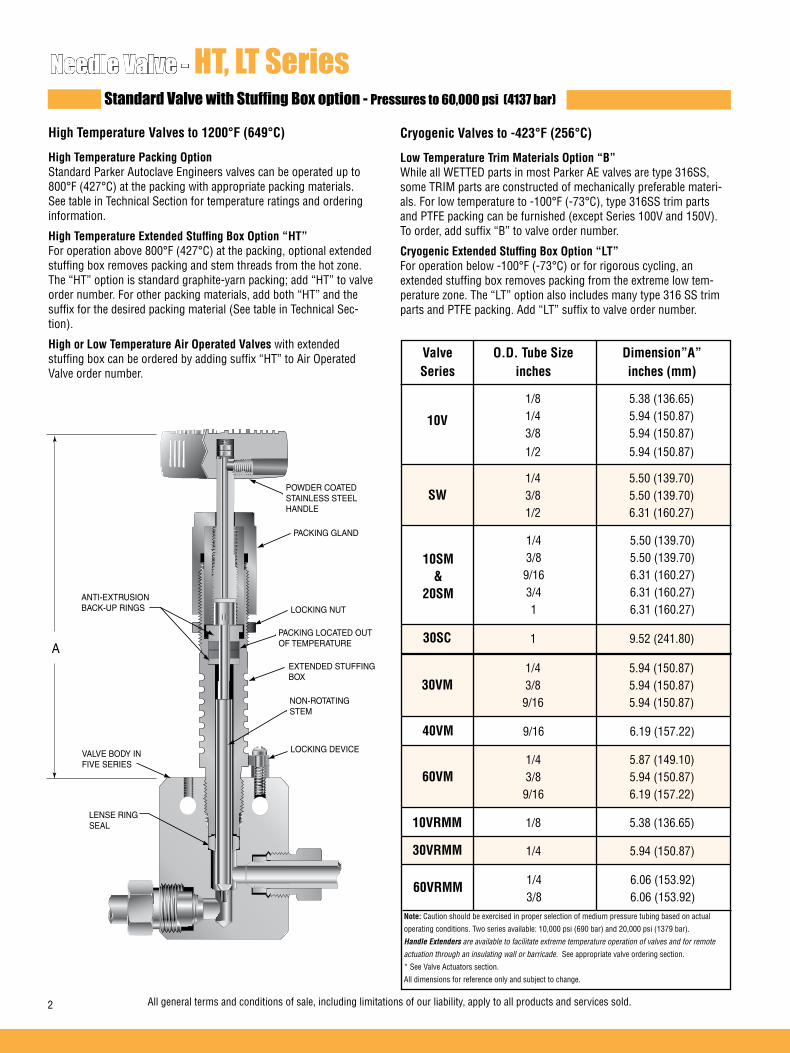
1/4 5.87 (149.10) 3/8 5.94 (150.87) 9/16 6.19 (157.22)
60VM
1/4 5.94 (150.87) 3/8 5.94 (150.87) 9/16 5.94 (150.87)
30VM
Standard Valve with Stuffing Box option - Pressures to 60,000 psi (4137 bar)
High Temperature Valves to 1200°F (649°C)
High Temperature Packing Option Standard Parker Autoclave Engineers valves can be operated up to 800°F (427°C) at the packing with appropriate packing materials. See table in Technical Section for temperature ratings and ordering information.
High Temperature Extended Stuffing Box Option “HT” For operation above 800°F (427°C) at the packing, optional extended stuffing box removes packing and stem threads from the hot zone. The “HT” option is standard graphite-yarn packing; add “HT” to valve order number. For other packing materials, add both “HT” and the suffix for the desired packing material (See table in Technical Sec-tion).
High or Low Temperature Air Operated Valves with extended stuffing box can be ordered by adding suffix “HT” to Air Operated Valve order number.
Cryogenic Valves to -423°F (256°C)
Low Temperature Trim Materials Option “B” While all WETTED parts in most Parker AE valves are type 316SS, some TRIM parts are constructed of mechanically preferable materi-als. For low temperature to -100°F (-73°C), type 316SS trim parts and PTFE packing can be furnished (except Series 100V and 150V). To order, add suffix “B” to valve order number.
Cryogenic Extended Stuffing Box Option “LT” For operation below -100°F (-73°C) or for rigorous cycling, an extended stuffing box removes packing from the extreme low tem-perature zone. The “LT” option also includes many type 316 SS trim parts and PTFE packing. Add “LT” suffix to valve order number.
Valve O.D. Tube Size Dimension”A” Series inches inches (mm)
1/8 5.38 (136.65) 1/4 5.94 (150.87) 3/8 5.94 (150.87)
1/2 5.94 (150.87)
10V
1/4 5.50 (139.70) 3/8 5.50 (139.70) 1/2 6.31 (160.27)
SW
1/4 5.50 (139.70) 3/8 5.50 (139.70) 9/16 6.31 (160.27) 3/4 6.31 (160.27) 1 6.31 (160.27)
10SM&
20SM
9/16 6.19 (157.22)40VM
1/8 5.38 (136.65)10VRMM
1/4 5.94 (150.87)
30VRMM
1/4 6.06 (153.92) 3/8 6.06 (153.92)
60VRMM
Note: Caution should be exercised in proper selection of medium pressure tubing based on actual
operating conditions. Two series available: 10,000 psi (690 bar) and 20,000 psi (1379 bar).
Handle Extenders are available to facilitate extreme temperature operation of valves and for remote
actuation through an insulating wall or barricade. See appropriate valve ordering section.
* See Valve Actuators section.
All dimensions for reference only and subject to change.
LOCKING NUTANTI-EXTRUSION BACK-UP RINGS
NON-ROTATINGSTEM
PACKING LOCATED OUT OF TEMPERATURE
EXTENDED STUFFING BOX
LOCKING DEVICEVALVE BODY IN FIVE SERIES
LENSE RINGSEAL
PACKING GLAND
A
POWDER COATEDSTAINLESS STEELHANDLE
Needle Valve - HT, LT Series
1 9.52 (241.80)
30SC
2 All general terms and conditions of sale, including limitations of our liability, apply to all products and services sold.

Pressures to 6,000 psi (414 bar)
Needle Valve - PV Series
Pressure Rating Tube psi (bar) Outside Connection Orifice @ Room Diameter Type Size Temperature** 1/4 TW/PW 3/16” 6,000 (414) 3/8 TW/PW 1/4” 6,000 (414) 1/2 TW/PW 1/4” 6,000 (414) 3/4 TW/PW 1/2” 6,000 (414) 10mm TW 6.50mm 6,000 (414) 12mm TW 6.50mm 6,000 (414) 14mm TW 6.50mm or 9.0mm 6,000 (414) 16mm TW 9.00mm or 11.0mm 6,000 (414) TW - Tube Weld PW - Pipe Weld Note: ** For temperature ratings see pressure/temperature rating guide chart below..
Ordering ProcedureFor complete information on available stem types, optional connections and additional valve options, see Needle Valve Options section or contact your Sales Representative.
Typical catalog number: PV4TW6MG
4-1/4”6-3/8”8-1/2”
12- 3/4”A-10mmB-12mmC-14mmD-16mm
TW - Tube Socket Weld
PW - Pipe Socket Weld
3 -3/16”
4 -1/4”
8 -1/2”
6M - 6.5mm
9M - 9.0mm
11M - 11.0mm
G - Graphic Yarn
GF - Grafoil
GPacking
6MPortSize
TWConnection
Type
4Outside Diameter
Tube Size
PVValveSeries
POWDER COATEDSTAINLESS STEELHANDLEPACKING GLAND
COLD WORKED TYPE 316 SS BODY
NON-ROTATINGSTEM
ADJUSTABLE PACKINGBELOW THREADS
LOCKING DEVICE
WELDED CONNECTIONMETAL-TO-METAL SEATING
CHOICE OF VEE OR REGULATING STEM TIP
ANTI-EXTRUSIONBACK-UP RINGS
INLET OUTLET
All general terms and conditions of sale, including limitations of our liability, apply to all products and services sold. 3
Size/Type
Outlet See Note
Note: Use if outlet connection is different - Example: PV4TWATW6M-G
See Technical Information section for curve details.

Valve Options Valve MaintenanceFor optional connection sizes, connection types,material or other options not listed contact your sales representative. Consult factory for availability of dissimilar end connections.
Repair Kits: add “R” to the front of valve catalog number for proper repair kit. (Example: RPV4TWG)
Valve Bodies: Valve bodies are available. Order using the eight (8) digit part number found on the valve drawing or contact your Sales Representative for information. Consult your Parker Autoclave Engineers representative for pricing on repair kits and valve bodies. Refer to the Tools, Installation, Operation and Mainte-nance section for proper maintenance procedures.
G - Packing gland mounting hole drill size * H Dimension is with stem in closed position. For prompt service, Parker G1 - Bracket mounting hole size All dimensions for reference only and subject to change. Autoclave Engineers stocks select Panel mounting drill size: 0.22” all valves. products. Consult factory.
Block Catalog Stem Diameter Orifice Thick- Valve Number Type Tube Diameter A B C D D1 E F G G1 H* M N ness Pattern
Dimensions - inches (mm)
2-Way Straight PV4TW3G VEE 1/4 0.187 2.00 1.00 1.41 1.41 2.00 3.00 0.75 0.22 4.43 0.62 0.38 0.75
(6.35) (4.75) (50.80) (25.40) (35.81) (35.81) (50.80) (76.20) (19.05) (5.59) (112.52) (15.75) (9.65) (19.05) 3/8 0.250 2.00 1.00 1.41 1.41 2.00 3.00 0.75 0.22 4.43 0.62 0.38 0.75 (9.53) (6.35) (50.80) (25.40) (35.81) (35.81) (50.80) (76.20) (19.05) (5.59) (112.52) (15.75) (9.65) (19.05) 14.00 6.5 50.80 25.40 35.81 35.81 50.80 76.20 19.05 5.59 111.00 15.75 9.65 19.05 (0.55) (0.26) (2.00) (1.00) (1.41) (1.41) (2.00) (3.00) (0.75) (0.22) (4.37) (0.62) (0.38) (0.75) 14.00 9.0 63.50 31.75 52.32 52.32 73.15 101.60 22.23 5.59 148.34 17.53 12.70 25.40 (0.55) (0.35) (2.50) (1.25) (2.06) (2.06) (2.88) (4.00) (0.88) (0.22) (5.84) (0.69) (0.50) (1.00)
Outside
See Figure 1
PVT6TW4G VEE
PVCTW6MG VEE
PVCTW9MG VEE
Metric (In)
Figure 1
2-Way Straight
H N
M M
F
G1
G
D1DE
BA
02-0117SE January2013© 2013 Parker Hannifin Corporation | Autoclave Engineers is a registered trademark of the Parker Hannifin Corporation
Parker Hannifin Manufacturing Ltd. Instrumentation Products Division, Europe Industrial Estate WhitemillWexford, Republic of IrelandPH: 353 53 914 1566FAX: 353 53 914 1582
Instrumentation Products DivisionAutoclave Engineers Operation8325 Hessinger DriveErie, Pennsylvania 16509-4679 USAPH: 814-860-5700 FAX: 814-860-5811www.autoclave.com
WARNING
FAILURE, IMPROPER SELECTION OR IMPROPER USE OF THE PRODUCTS AND/OR SYSTEMS DESCRIBED HEREIN OR RELATED ITEMS CAN CAUSE DEATH, PERSONAL INJURY AND PROPERTY DAMAGE.This document and other information from Parker Hannifin Corporation, its subsidiaries and authorized distributors provide product and/or system options for further investigation by users having technical expertise. It is important that you analyze all aspects of your application and review the information concerning the product or system in the current product catalog. Due to the variety of operating conditions and applications for these products or systems, the user, through its own analysis and testing, is solely responsible for making the final selection of the products and systems and assuring that all performance, safety and warning requirements of the application are met. The products described herein, including without limitation, product features, specifications, designs, availability and pricing, are subject to change by Parker Hannifin Corporation and its subsidiaries at any time without notice.
Offer of Sale
The items described in this document are available for sale by Parker Hannifin Corporation, its subsidiaries or its authorized distributors. Any sale contract entered by Parker will be governed by the provisions stated in Parker's standard terms and conditions of sale (copy available upon request).
ISO-9001 Certified
Caution! Do not mix or interchange parts or tubing with those of other manufacturers. Doing so is unsafe and will void warranty.
Caution! Parker Autoclave Engineers Valves, Fittings and Tools are not designed to work with common commercial instrument tubing and will only work with tubing built to Parker Autoclave Engineers AES Specifications. Failure to do so will void warranty.
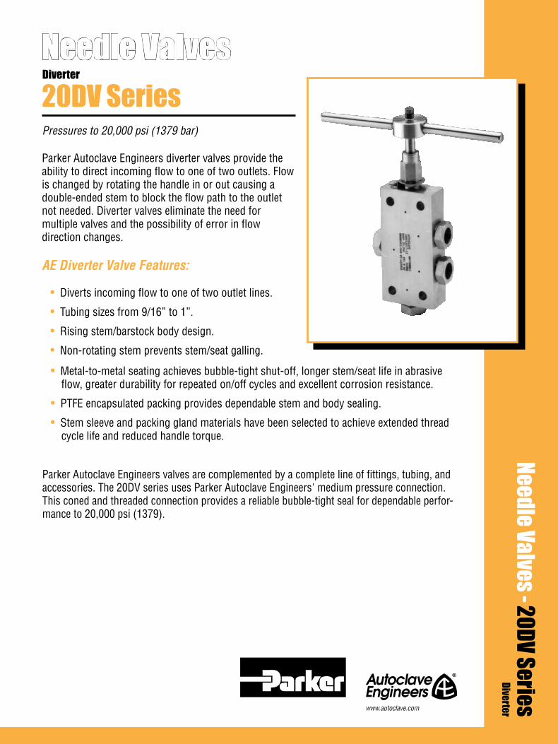
Parker Autoclave Engineers diverter valves provide the ability to direct incoming flow to one of two outlets. Flow is changed by rotating the handle in or out causing a double-ended stem to block the flow path to the outlet not needed. Diverter valves eliminate the need for multiple valves and the possibility of error in flow direction changes.
AE Diverter Valve Features:
• Diverts incoming flow to one of two outlet lines.
• Tubing sizes from 9/16” to 1”.
• Rising stem/barstock body design.
• Non-rotating stem prevents stem/seat galling.
Needle Valves
Pressures to 20,000 psi (1379 bar)
20DV SeriesDiverter
• Metal-to-metal seating achieves bubble-tight shut-off, longer stem/seat life in abrasive flow, greater durability for repeated on/off cycles and excellent corrosion resistance.
• PTFE encapsulated packing provides dependable stem and body sealing.
• Stem sleeve and packing gland materials have been selected to achieve extended thread cycle life and reduced handle torque.
Parker Autoclave Engineers valves are complemented by a complete line of fittings, tubing, and accessories. The 20DV series uses Parker Autoclave Engineers' medium pressure connection. This coned and threaded connection provides a reliable bubble-tight seal for dependable perfor-mance to 20,000 psi (1379).
Needle Valves - 20DV SeriesDiverterwww.autoclave.com
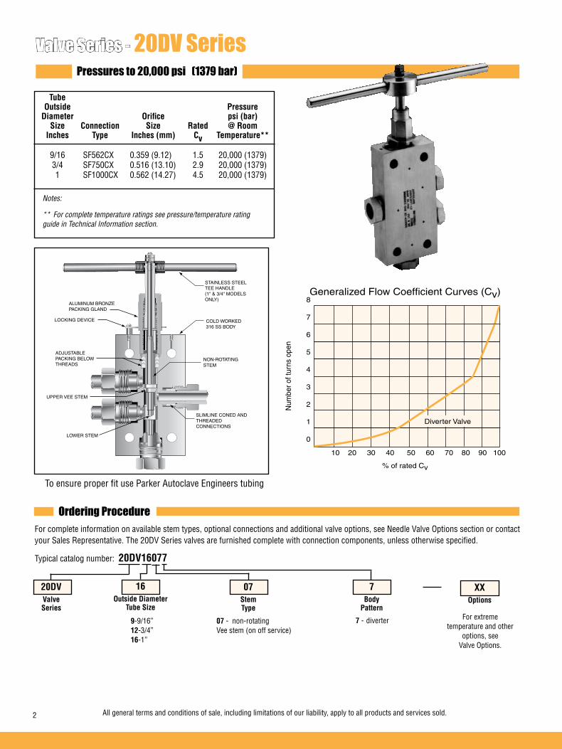
Valve Series - 20DV SeriesPressures to 20,000 psi (1379 bar)
To ensure proper fit use Parker Autoclave Engineers tubing
Generalized Flow Coefficient Curves (Cv)
% of rated Cv
Num
ber o
f tur
ns o
pen
10 20 30 40 50 60 70 80 90 100
8
7
6
5
4
3
2
1
0
Diverter Valve
Ordering ProcedureFor complete information on available stem types, optional connections and additional valve options, see Needle Valve Options section or contact your Sales Representative. The 20DV Series valves are furnished complete with connection components, unless otherwise specified.
Typical catalog number: 20DV16077
9-9/16”12-3/4”16-1”
07 - non-rotating Vee stem (on off service)
7 - diverter For extreme temperature and other
options, see Valve Options.
XXOptions
7Body
Pattern
07StemType
16Outside Diameter
Tube Size
20DVValveSeries
STAINLESS STEEL TEE HANDLE(1" & 3/4" MODELS ONLY)
LOCKING DEVICE
ALUMINUM BRONZE PACKING GLAND
COLD WORKED 316 SS BODY
ADJUSTABLE PACKING BELOW THREADS
NON-ROTATING STEM
UPPER VEE STEM
SLIMLINE CONED AND THREADED CONNECTIONS
LOWER STEM
All general terms and conditions of sale, including limitations of our liability, apply to all products and services sold.2
Tube Outside Pressure Diameter Orifice psi (bar) Size Connection Size Rated @ Room Inches Type Inches (mm) Cv Temperature** 9/16 SF562CX 0.359 (9.12) 1.5 20,000 (1379) 3/4 SF750CX 0.516 (13.10) 2.9 20,000 (1379) 1 SF1000CX 0.562 (14.27) 4.5 20,000 (1379)
Notes:
** For complete temperature ratings see pressure/temperature rating guide in Technical Information section.

Valve Options Valve MaintenanceExtreme Temperatures Standard Parker Autoclave Engineers valves with PTFE packing may be operated to 450°F (232°C). High temperature packing and/or extended stuffing box is available for service from -423°F (-252°C) to 1200°F (649°C) by adding the following suffixes to catalog order number.
HT extended stuffing box valve with graphite braided yarn packing to 1200°F (648°C).B standard valve with cryogenic trim materials and PTFE packing to -100°F (-73°C).LT extended stuffing box valve with PTFE packing and cryogenic trim materials to -423°F (-252°C).K anti-vibe collet gland assembly.
Repair Kits: add “R” to the front of valve catalog number for proper repair kit. (Example: R20DV16077)
Valve Bodies: Valve bodies are available. Order using the eight (8) digit part number found on the valve drawing or contact your Sales Representative for information.Consult your Parker Autoclave Engineers representative for pricing on repair kits and valve bodies. Refer to the Tools, Installation, Operation and Mainte-nance section for proper maintenance procedures.
20DV9077 VEE 20DV12077 VEE
9/16 0.359 2.50 1.25 0.53 2.41 1.75/1.63 4.69 4.00 1.00 0.34 8.88 0.69 0.50 1.00
(14.29) (9.12) (63.50) (31.75) (13.46) (61.21) (44.45/41.40) (119.13) (101.60) (25.40) (8.64) (225.55) (17.53) (12.70) (25.40)
3/4 0.516 3.00 1.50 0.62 3.00 2.13/1.81 5.69 10.25 1.12 0.44 10.12 0.88 0.62 1.38
(19.05) (13.11) (76.20) (38.10) (15.75) (76.20) (54.10/45.97) (144.53) (260.35) (28.45) (11.18) (257.05) (22.35) (15.75) (35.05)
1 0.562 4.12 2.06 0.72 3.75 2.81/2.62 7.25 10.25 1.62 0.56 12.79 1.25 1.12 1.75
(25.40) (14.27) (104.65) (52.33) (18.29) (95.25) (71.37/66.55) (184.15) (260.35) (41.15) (14.22) (324.87) (31.75) (28.45) (44.45)
G - Packing gland mounting hole drill size * H Dimension is with stem in closed position. For prompt service, Parker G1 - Bracket mounting hole size All dimensions for reference only and subject to change. Autoclave Engineers stocks select Panel mounting drill size: 0.22” all valves. products. Consult factory.
Block Catalog Stem Diameter Orifice Thick- Number Type Tube Diameter A B C D D1 E F G G1 H* M N ness
Dimensions - inches (mm)Outside
Diverter 20DV Series
Figure 1
See Figure 1
20DV16077 VEE
HN
M M
F
G1
G
D1
E
CBA
D1
D
N
All general terms and conditions of sale, including limitations of our liability, apply to all products and services sold. 3
Valve Pattern

02-0118SE January2013© 2013 Parker Hannifin Corporation | Autoclave Engineers is a registered trademark of the Parker Hannifin Corporation
Parker Hannifin Manufacturing Ltd. Instrumentation Products Division, Europe Industrial Estate WhitemillWexford, Republic of IrelandPH: 353 53 914 1566FAX: 353 53 914 1582
Instrumentation Products DivisionAutoclave Engineers Operation8325 Hessinger DriveErie, Pennsylvania 16509-4679 USAPH: 814-860-5700 FAX: 814-860-5811www.autoclave.com
WARNING
FAILURE, IMPROPER SELECTION OR IMPROPER USE OF THE PRODUCTS AND/OR SYSTEMS DESCRIBED HEREIN OR RELATED ITEMS CAN CAUSE DEATH, PERSONAL INJURY AND PROPERTY DAMAGE.This document and other information from Parker Hannifin Corporation, its subsidiaries and authorized distributors provide product and/or system options for further investigation by users having technical expertise. It is important that you analyze all aspects of your application and review the information concerning the product or system in the current product catalog. Due to the variety of operating conditions and applications for these products or systems, the user, through its own analysis and testing, is solely responsible for making the final selection of the products and systems and assuring that all performance, safety and warning requirements of the application are met. The products described herein, including without limitation, product features, specifications, designs, availability and pricing, are subject to change by Parker Hannifin Corporation and its subsidiaries at any time without notice.
Offer of Sale
The items described in this document are available for sale by Parker Hannifin Corporation, its subsidiaries or its authorized distributors. Any sale contract entered by Parker will be governed by the provisions stated in Parker's standard terms and conditions of sale (copy available upon request).
ISO-9001 Certified
Caution! Do not mix or interchange parts or tubing with those of other manufacturers. Doing so is unsafe and will void warranty.
Caution! Parker Autoclave Engineers Valves, Fittings and Tools are not designed to work with common commercial instrument tubing and will only work with tubing built to Parker Autoclave Engineers AES Specifications. Failure to do so will void warranty.

Parker Autoclave Engineers’ yoke valves are extra heavy-duty, plant grade instrument valves for industrial and severe service applications. Yoke valves feature low closing torque for ease of operation and are designed for use with Parker Autoclave Engineers medium and high pressure tubing and fittings.
Yoke Valve Features:
• Tubing sizes from 9/16” to 1”.
• Rising stem/barstock body design.
• Non-rotating stem prevents stem/seat galling.
• Metal-to-metal seating achieves bubble-tight shut-off, longer stem/seat life in abrasive flow, greater durability for repeated on/off cycles and excellent corrosion resistance.
Needle Valves
Pressures to 50,000 psi (3447 bar)
Y SeriesYoke
• PTFE encapsulated packing provides dependable stem and body sealing.
• Stem sleeve and packing gland materials have been selected to achieve extended thread cycle life and reduced handle torque.
• Choice of Vee or Regulating stem tips.
• Available in two body patterns.
• Optional materials for cryogenic and other applications.
Parker Autoclave Engineers valves are complemented by a complete line of fittings, tubing, and accessories.
Needle Valves - Y SeriesYoke
www.autoclave.com

Valve Series - Y SeriesPressures to 50,000 psi (3447 bar)
To ensure proper fit use Parker Autoclave Engineers tubing
Generalized Flow Coefficient Curves (Cv)
% of rated Cv
Nu
mb
er o
f tu
rns
op
en
10 20 30 40 50 60 70 80 90 100
7
6
5
4
3
2
1
0
15Y & 43Y Regulating Stem
15Y & 43Y Vee Stem
50Y Regulating Stem
50Y Vee Stem
Ordering ProcedureFor complete information on available stem types, optional connections and additional valve options, see Needle Valve Options section or contact your Sales Representative. The Y Series valves are furnished complete with connection components, unless otherwise specified.
Typical catalog number: 50Y9071
9-9/16”12-3/4”16-1.0”
07 - non-rotating Vee stem (on-off service)
08 - non-rotating Regulating stem (tapered tip for Regulating and shutoff)
87 - Vee stem with replaceable seat
88 - Regulating stem with replaceable seat
1 - two-way straight2 - two-way angle
TG - PTFE Glass Packing B - Cryogenic Trim and PTFE Packing
See Valve optionsfor ratings
XXOptions
1Body
Pattern
07Stem/Seat
Type
9Outside Diameter
Tube Size
50YValveSeries
STAINLESS STEEL TEE HANDLE(except 9/16 replaceable seat)
PACKING GLAND
COLD WORKEDTYPE 316 SSBODY
NON-ROTATINGSTEM
TYPE 316 SS BONNET
ADJUSTABLE PACKING BELOW THREADS
AE MEDIUM PRESSURE CONED-AND-THREADED CONNECTIONS ON SERIES 15Y, AE HIGH PRESSURE ON 50Y AND
15Y43Y50Y
2 All general terms and conditions of sale, including limitations of our liability, apply to all products and services sold.
Tube Outside Pressure Diameter Orifice psi (bar) Size Connection Size Rated @ Room Inches Type Inches (mm) Cv * Temperature** 9/16 F562C 0.188 (4.76) 0.66 50,000 (3447) 3/4 SF750CX 0.438 (11.13) 2.41 15,000 (1034) 1 SF1000CX 0.562(14.27) 3.15 15,000 (1034) 1 F1000C43 0.375 (9.53) 2.3 43,000 (2965) Notes: * CV values shown are for 2-way straight valve pattern. For 2-way angle patterns, increase CV value 50%.
** For complete temperature ratings see pressure/temperature rating guide in Technical Information section.

2-Way Straight
2-Way Angle
2-Way Angle/Replaceable Seat
Valve MaintenanceExtreme Temperatures Standard Parker Autoclave Engineers valves with PTFE packing may be operated to 450°F (232°C). High temperature packing is available for service from 0°F (-17.8°C) to 600°F (316°C) by adding the follow-ing suffixes to catalog order number.
TG standard valve with PTFE glass packing to 600°F (316°C).B standard valve with cryogenic trim materials and PTFE packing to -100°F (-73°C).
Repair Kits: add “R” to the front of valve catalog number for proper repair kit. (Example: R50Y9071)
Valve Bodies: Valve bodies are available. Order using the eight (8) digit part number found on the valve drawing or contact your Sales Representative for information.Consult your Parker Autoclave Engineers representative for pricing on repair kits and valve bodies. Refer to the Tools, Installation, Operation and Mainte-nance section for proper maintenance procedures.
15Y12071 VEE 15Y12081 REG 15Y16071 VEE 15Y16081 REG 43Y16071 VEE 43Y16081 REG 50Y9071 VEE 50Y9081 REG
3/4 0.438 3.00 1.50 0.63 .75 1.50 3.50 8.00 0.28 9.38 1.13 0.88 1.38
(19.05) (11.13) (76.20) (38.10) (15.88) (19.05) (38.10) (88.90) (203.20) (7.11) (238.25) (28.58) (22.23) (34.93)
1.00 0.562 4.13 2.06 0.63 .88 1.88 4.13 10.25 0.28 10.00 1.50 1.13 1.75
(25.40) (14.27) (104.78) (52.39) (15.88) (22.35) (47.75) (104.78) (260.35) (7.11) (254.00) (38.10) (28.58) (44.45)
1.00 0.375 4.13 2.07 0.72 1.00 1.88 4.13 10.25 0.28 9.56 1.50 1.00 1.75
(25.40) (9.53) (104.90) (52.45) (18.29) (25.40) (47.75) (104.78) (260.35) (7.11) (242.82) (38.10) (25.40) (44.45)
9/16 0.188 3.00 1.50 0.56 .688 1.25 3.25 13.00 0.50 8.69 1.13 0.88 1.38
(14.27) (4.78) (76.20) (38.10) (14.27) (17.48) (31.75) (82.55) (330.20) (12.70) (220.73) (28.58) (22.23) (34.93)
G - Bracket mounting hole size * H Dimension is with stem in closed position. For prompt service, Parker Autoclave All dimensions for reference only and subject to change. Engineers stocks select products. Consult factory.
Block Catalog Stem Diameter Orifice Thick- Number Type Tube Diameter A B C D D1 E F G G1 H* M N ness
Dimensions - inches (mm)Outside
See Figure 1
15Y12072 VEE 15Y12082 REG 15Y16072 VEE 15Y16082 REG 43Y16072 VEE 43Y16082 REG 50Y9072 VEE 50Y9082 REG
3/4 0.438 3.00 1.50 0.63 1.75 3.75 8.00 0.28 9.63 1.13 0.88 1.38
(19.05) (11.13) (76.20) (38.10) (15.88) (44.45) (95.25) (203.20) (7.11) (244.48) (28.58) (22.23) (34.93)
1.00 0.562 4.13 2.06 0.63 2.25 4.50 10.25 0.28 10.38 1.50 1.13 1.75
(25.40) (14.27) (104.90) (52.39) (15.88) (57.15) (114.30) (260.35) (7.11) (263.53) (38.10) (28.58) (44.45)
1.00 0.375 4.13 2.07 0.72 2.31 4.56 10.25 0.28 10.80 1.50 1.00 1.75
(25.40) (9.53) (104.90) (52.45) (18.29) (58.67) (115.82) (260.35) (7.11) (274.32) (38.10) (25.40) (44.45)
9/16 0.188 3.00 1.50 0.56 1.50 3.50 13.00 0.50 8.81 1.13 0.88 1.38
(14.27) (4.78) (76.20) (38.10) (14.27) (38.10) (88.90) (330.20) (12.70) (223.82) (28.58) (22.23) (34.93)
See Figure 2
15Y12872 VEE 15Y12882 REG 15Y16872 VEE 15Y16882 REG 43Y16872 VEE 43Y16882 REG 50Y9872 VEE 50Y9882 REG
3/4 0.438 3.00 1.50 0.63 2.06 4.00 8.00 0.28 11.31 1.13 0.88 1.38
(19.05) (11.13) (76.20) (38.10) (15.88) (52.32) (101.60) (203.20) (7.11) (287.27) (28.58) (22.23) (34.93)
1.00 0.562 4.13 2.06 0.63 2.06 4.13 10.25 0.28 11.75 1.50 1.03 1.75
(25.40) (14.27) (104.78) (52.39) (15.88) (52.32) (104.78) (260.35) (7.11) (298.45) (38.10) (26.16) (44.45)
1.00 0.375 4.13 2.07 0.72 2.13 4.38 10.25 0.28 11.95 1.50 1.00 1.75
(25.40) (9.53) (104.78) (52.45) (18.29) (54.10) (111.25) (260.35) (7.11) (303.53) (38.10) (25.40) (44.45)
9/16 0.188 3.00 1.50 0.56 1.38 3.38 4.00 0.28 12.12 1.13 1.06 1.38
(14.27) (4.78) (76.20) (38.10) (14.27) (35.05) (85.73) (101.60) (7.11) (307.85) (28.58) (26.97) (34.93)
See Figure 3
2-Way Straight
Figure 1
H
N
F
D1ED
B
AM
C
G1
M
2-Way Angle
Figure 2
H
N
F
D E
B
A
C
G1
M M
2-Way Angle/Replaceable Seat
Figure 3
H
N
F
D E
B
A
C
G1
M M
All general terms and conditions of sale, including limitations of our liability, apply to all products and services sold. 3
Valve Pattern
Valve Options

02-0119SE January2013© 2013 Parker Hannifin Corporation | Autoclave Engineers is a registered trademark of the Parker Hannifin Corporation
Parker Hannifin Manufacturing Ltd. Instrumentation Products Division, Europe Industrial Estate WhitemillWexford, Republic of IrelandPH: 353 53 914 1566FAX: 353 53 914 1582
Instrumentation Products DivisionAutoclave Engineers Operation8325 Hessinger DriveErie, Pennsylvania 16509-4679 USAPH: 814-860-5700 FAX: 814-860-5811www.autoclave.com
WARNING
FAILURE, IMPROPER SELECTION OR IMPROPER USE OF THE PRODUCTS AND/OR SYSTEMS DESCRIBED HEREIN OR RELATED ITEMS CAN CAUSE DEATH, PERSONAL INJURY AND PROPERTY DAMAGE.This document and other information from Parker Hannifin Corporation, its subsidiaries and authorized distributors provide product and/or system options for further investigation by users having technical expertise. It is important that you analyze all aspects of your application and review the information concerning the product or system in the current product catalog. Due to the variety of operating conditions and applications for these products or systems, the user, through its own analysis and testing, is solely responsible for making the final selection of the products and systems and assuring that all performance, safety and warning requirements of the application are met. The products described herein, including without limitation, product features, specifications, designs, availability and pricing, are subject to change by Parker Hannifin Corporation and its subsidiaries at any time without notice.
Offer of Sale
The items described in this document are available for sale by Parker Hannifin Corporation, its subsidiaries or its authorized distributors. Any sale contract entered by Parker will be governed by the provisions stated in Parker's standard terms and conditions of sale (copy available upon request).
ISO-9001 Certified
Caution! Do not mix or interchange parts or tubing with those of other manufacturers. Doing so is unsafe and will void warranty.
Caution! Parker Autoclave Engineers Valves, Fittings and Tools are not designed to work with common commercial instrument tubing and will only work with tubing built to Parker Autoclave Engineers AES Specifications. Failure to do so will void warranty.

Parker Autoclave Engineer’s Needle Valves can be supplied with a number of options to meet your requirements. These include various materials of construction, packing material, high temperature packing, handle colors, stem options, custom valves, pneumatic actuators, and a number of other options.
The following pages provide details on these options. For additional or technical information not found in this section, please consult the factory or local distributor.
Needle Valves - OptionsNeedle ValvesOptions
www.autoclave.com

Needle Valves - Stem OptionsThree Stem Types
Three types of stems are offered by Parker Autoclave Engineers: Vee, Regulating and MicroMetering. Both Vee and Regulating stems are interchangable on most Parker AE valves and provide bubble-tight shut-off against liquids and gases.
The Vee stem is used for direct on-off, metal-to-metal shut-off with quick-opening flow characteristics.
In some applications, more precise flow control is required than is possible with a Vee stem. For these cases, Autoclave offers a non-rotating, two-piece regulat-ing stem which can be used for both control and shut-off. This stem has a 4° taper at the tip in conjunction with a standard 60° section for shut-off. While it is not as precise as the control as-sociated with the MicroMetering stem, especially with smaller flows, it does offer substantially better control than the Vee stem.
Where precise control of small flows is required, Autoclave offers special MicroMetering valves. For complete information on MicroMetering valves, refer to Micro-Metering in the Needle Valve section.
Optional Materials
VEE Stem Regulating Stem MicroMetering Stem
To order optional materials for wetted parts, add the following designations to the order number. 316L Type 316 extra low carbon stainless steel HB *Hastelloy B-2 HC *Hastelloy C276 wetted parts IN *Inconel 600 IN625 *Inconel 625 IN825 *Incoloy 825 KMO *Monel K500 MO *Monel 400 or 450 NI Nickel 200 TI Titanium grade 2Note: For duplex, super duplex and other materials contact your sales representative.
*Trademark names
All general terms and conditions of sale, including limitations of our liability, apply to all products and services sold.2

Air Operated Valves
Refer to Valve Actuators section for available models.
Optional Connections
In addition to standard tube connections, Parker Autoclave Engineers can supply many valve and fitting series with such optional end connections as Female or Male NPT, Socket Weld to O.D. tube size, or nominal pipe size, Female “AN” (MS 33649), Male “AN (MS 33656), Butt Weld and British straight thread. Contact factory for current information. Metric sizes can be supplied on most Parker Autoclave Engineers valves and fittings on special order.
Anti-Vibration AdderFor valves or other components supplied with anti-vibration option, add -K to catalog number. See fitting and tubing sections for anti-vibration information.
Stem and Handle ExtendersStem Extenders are offered for high or low temperature operation on most Parker Autoclave Engineers valves. They are also useful for remote actuation, such as behind a barricade. To order any valve with a Stem Extender, add “ES” and the length (6”, 12”, 18” or 24”) to the beginning of the valve catalog number: e.g. ES12-30VM4071. Other lengths on special order. To order stem extender only, please provide extender number and the prefix of the valve model. Ex: ES12-20SM6 (handle not included.)
Abrasive or Highly Erosive Service OptionFor service conditions where high flows, erosive mediums, or high pressures cause premature wear on stems and seats, N-Dura coating can be supplied to increase component life.
N-Dura coating is specifically used to enhance stem and seat life by providing a protective coating over a base substrate. This creates a thin, hard, protective coating with no effects of brittleness. The coating will not peel, chip or flake off the base material. The coating hardness is in a range of minimum 85 Rc surpassing other coatings and most materials.
The additional performance characteristics provided with the coating are reduced friction, corrosion resis-tance exceeding 400 stainless steel, and operating temperature ranges from -300°F to 1200°F.The coating has been tested in erosive applications, yielding far better results than Stellite®, which has been utilized extensively in these applications. With few exceptions, most major ferrous and non ferrous materials can be successfully coated.
Most valves in this catalog are available with N-Dura coated stems or with both N-Dura coated stems and replaceable seats. This coating is available for all stem options. To order both N-Dura stems on any valve pattern, add suffix “CS” to the catalog model number. To order both N-Dura coated stems and N-Dura coated replaceable seats (available on 2-way angle replaceable seat pattern only) add suffix “CSS” to the catalog number. Stellite® is available as a special upon request.
Optional Valve HandlesBlue powder coated stainless handles are standard on the majority of the valve series. Stainess handles can be purchased in different colors if required, contact the factory for color options.
Packing Options
Refer to the valve model required, and see valve options in that section.
All general terms and conditions of sale, including limitations of our liability, apply to all products and services sold. 3
"ES"Specify desired
extra lengthin inches
Exception: Heavy-duty Stainless Steel T-handles assemblies are standard on our larger valves, see detailed information on each section for handles used.
Panel MountingMost Parker Autoclave Engineers valve series can be panel mounted through the locking device screw hole and a corresponding hole opposite the packing gland. To order a set of two panel mounting screws, add PM to the catalog order number.
Handle Lockouts: Handle lockouts are available to lockout valves in the open or closed position preventing unauthorized personnel from actuating valves during shutdowns or emergency situations. Lockouts consist of two halves that completely cover the valve handle and can be locked for security. They are constructed of durable plastic resistant to abrasion, solvents, and chemical agents. Consult factory for details.To order lockouts with valves add -L to part number.Lockout part numbers: 90088 - 2.5" (63.5) to 5.0" (127.0) handle size 90194 - 6.5" (165.1) to 10.0" (254.0) handle sizeNote: Modifications may be required to some valves to use lockouts if purchased separately. See page 1 of ball valve options for photo of clamp style lockout.
Note: Many standard and special options and accessories for Parker Autoclave Engineers valves are listed here. Not all options apply to all valve series - see individual ordering pages for specifics. Some options listed here are special order options with prices quoted on application. See Custom Valves/Manifolds section for other options.
For prompt service, Parker Autoclave Engineers stocks select products. Consult your local representative.
02-0120SE January2013© 2013 Parker Hannifin Corporation | Autoclave Engineers is a registered trademark of the Parker Hannifin Corporation
Parker Hannifin Manufacturing Ltd. Instrumentation Products Division, Europe Industrial Estate WhitemillWexford, Republic of IrelandPH: 353 53 914 1566FAX: 353 53 914 1582
Instrumentation Products DivisionAutoclave Engineers Operation8325 Hessinger DriveErie, Pennsylvania 16509-4679 USAPH: 814-860-5700 FAX: 814-860-5811www.autoclave.com
WARNING
FAILURE, IMPROPER SELECTION OR IMPROPER USE OF THE PRODUCTS AND/OR SYSTEMS DESCRIBED HEREIN OR RELATED ITEMS CAN CAUSE DEATH, PERSONAL INJURY AND PROPERTY DAMAGE.This document and other information from Parker Hannifin Corporation, its subsidiaries and authorized distributors provide product and/or system options for further investigation by users having technical expertise. It is important that you analyze all aspects of your application and review the information concerning the product or system in the current product catalog. Due to the variety of operating conditions and applications for these products or systems, the user, through its own analysis and testing, is solely responsible for making the final selection of the products and systems and assuring that all performance, safety and warning requirements of the application are met. The products described herein, including without limitation, product features, specifications, designs, availability and pricing, are subject to change by Parker Hannifin Corporation and its subsidiaries at any time without notice.
Offer of Sale
The items described in this document are available for sale by Parker Hannifin Corporation, its subsidiaries or its authorized distributors. Any sale contract entered by Parker will be governed by the provisions stated in Parker's standard terms and conditions of sale (copy available upon request).
ISO-9001 Certified
Caution! Do not mix or interchange parts or tubing with those of other manufacturers. Doing so is unsafe and will void warranty.
Caution! Parker Autoclave Engineers Valves, Fittings and Tools are not designed to work with common commercial instrument tubing and will only work with tubing built to Parker Autoclave Engineers Specifications AES-222. Failure to do so will void warranty.
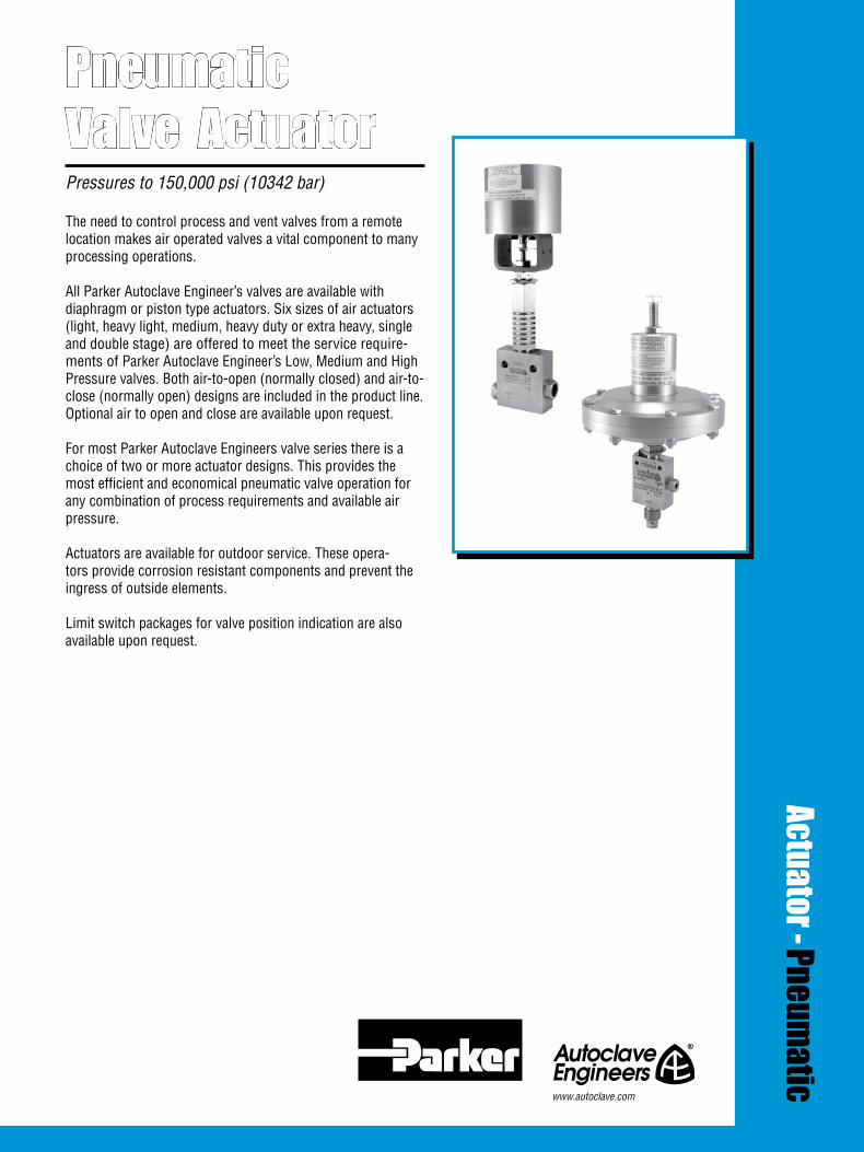
Pneumatic Valve Actuator
Actuator - Pneumatic
Pressures to 150,000 psi (10342 bar) The need to control process and vent valves from a remote location makes air operated valves a vital component to many processing operations. All Parker Autoclave Engineer’s valves are available with diaphragm or piston type actuators. Six sizes of air actuators (light, heavy light, medium, heavy duty or extra heavy, single and double stage) are offered to meet the service require-ments of Parker Autoclave Engineer’s Low, Medium and High Pressure valves. Both air-to-open (normally closed) and air-to-close (normally open) designs are included in the product line. Optional air to open and close are available upon request. For most Parker Autoclave Engineers valve series there is a choice of two or more actuator designs. This provides the most efficient and economical pneumatic valve operation for any combination of process requirements and available air pressure.
Actuators are available for outdoor service. These opera-tors provide corrosion resistant components and prevent the ingress of outside elements.
Limit switch packages for valve position indication are also available upon request.
www.autoclave.com


Pneumatic Valve Actuators - General informationPressures to 150,000 psi (10342 bar)
Pneumatic Actuator Pressures to 150,000 psi (10342 bar)
Six sizes of air operators (light, heavy light, medium, heavy duty or extra heavy, single and double stage) are offered for remote on-off operation or automatic operation of Parker Autoclave Engineer’s low, medium or high pressure valves. The actuators are available in air-to-open (normally closed) and air-to-close (normally open) designs.
Remote on-offParker Autoclave Engineer’s air-operated valves (ATO- Air-To-Open or ATC-Air-To-Close) can be controlled by a 3-way manual low pressure valve or by a low pressure solenoid valve. These are actuated by either a manual switch or an automatic control instrument. Parker Autoclave Engineer’s air-operated, high pressure valves permit process control from a remotely located panel without the necessity of piping high pressure lines to the control panel. Safety is greatly increased and process “hold-up” is reduced. Prudent selection of ATO or ATC valves, together with the air controlling devices, permits the design of systems to “fail safe” in either the closed or open condition in the event of loss of operating air, or electrical failure, or malfunction.Where explosion proof conditions are a requirement, pneumat-ic actuated valves can be considered. Remote mounting of the solenoid valve removes the potential from the hazardous area.
Ordering ProcedureTo order a valve with an air operator, select the duty rating and type of the air operator from the chart below. Add the air operator identifying suffix to the catalog number of the Parker Autoclave Engineer’s valve. To order a 2-way straight, 30VM vee stem, 9/16” valve with a medium duty air-to-close air operator, specify: ex: 30VM9071-C1S for a yoke style piston air actu-ated valve or 30VM9071-CM for an integral style diaphragm air operated valve.
To order the same valve with an extended high temperature stuffing box, add HT to the ordering number: ex: 30VM9071-C1SHT or 30VM9071-CMHT.
To order a dual air operator manifold valve, specify both operators if different. The same valve with a medium duty ATC on one stem and a medium duty ATO on the other, specify: ex: 30VM9075-C1SO1S.
To order a valve with operators for outdoor service add an “OD” suffix to the catalog number.
Note: Ordering air actuated valves models with regulating stems is not recommend. These are open/close actuators and will not regulate flow.
AOV
Solenoid Valve
Air-in
Manual electric switch orinstrument for remote operation
AOV Air-in
Vent
Vent
Manual 3-way valve for remotecontrol of diaphragm air
2
Duty Rating Operator Type Ordering Suffix
Light
DiaphragmAir-to-open OL
Air-to-close CL
PistonAir-to-open OLP
Air-to-close CLP
Mini-Light PistonAir-to-open OHLP
Air-to-close CHLP
Medium
DiaphragmAir-to-open OM
Air-to-close CM
PistonAir-to-open O1S
Air-to-close C1S
Heavy
DiaphragmAir-to-open OH
Air-to-close CH
PistonAir-to-open O2S
Air-to-close C2S
Extra HeavySingle Stage Piston
Air-to-open HO1S
Air-to-close HC1S
Extra HeavyDouble Stage Piston
Air-to-open HO2S
Air-to-close HC2S
Outdoor Service Actuators
Medium PistonAir-to-open O1SOD
Air-to-close C1SOD
Heavy PistonAir-to-open O2SOD
Air-to-close C2SOD
Extra HeavySingle Stage Piston
Air-to-open HO1SOD
Air-to-close HC1SOD
Extra HeavyDoubl Stage Piston
Air-to-open HO2SOD
Air-to-close HC2SOD

Pneumatic Valve Actuators - Actuator Quick Selector GuideThis table allows the designer to quickly select an appropriate air actuator based on valve style and size, maximum system operating pressure and maximum available air pressure. For example, if the system operating pressure is 25,000 psi (1724 bar) and the
available air pressure is 60 psi (4.14 bar) and an air-to-open (spring fail closed) valve is required, a 30VM or 60VM valve with a heavy duty air operator can be used. More specific sizing data is available in the sizing charts on the following pages.
ValveSeries
Air-to-Close
Light Medium Heavy Extra HeavySingle Stage
Extra HeavyTwo Stage
SystemPressurepsi (bar)
AirPressurepsi (bar)
SystemPressurepsi (bar)
AirPressurepsi (bar)
SystemPressurepsi (bar)
AirPressurepsi (bar)
SystemPressurepsi (bar)
AirPressurepsi (bar)
SystemPressurepsi (bar)
AirPressurepsi (bar)
Tube Outside
Diameter in (mm)
10V
SW
10SM
20SM
NOTE: For 10P and 15P series pipe valves see sizing data tables.
Maximum pressure rating is based on the lowest rating of any component. Actual working pressure may be determined by tubing pressure rating, if lower.
All dimensions for reference only and subject to change.For prompt service, Parker Autoclave Engineers stocks select products. Consult your local representative.
3
1/8 15,000 100 15,000 30 (3.18) (1034.20) (6.89) (1034.20) (2.07)
1/4 10,000 100 15,000 40 (6.35) (689.46) (6.89) (1034.20) (2.76)
3/8 10,000 100 15,000 40 (9.52) (689.46) (6.89) (1034.20) (2.76)
1/2 10,000 65 (12.70) (689.46) (4.48)
1/4 15,000 65 (6.35) (1034.20) (4.48)
3/8 15,000 90 15,000 50 (9.52) (1034.20) (6.21) (1034.20) (3.45)
1/2 8,000 100 10,000 60 (12.70) (551.57) (6.89) (689.46) (4.13)
9/16 8,600 100 10,000 55 10,000 45 10,000 20 (14.27) (592.94) (6.89) (689.45) (3.79) (689.45) (3.10) (689.46) (1.38)
3/4 4,,800 100 10,000 100 10,000 75 10,000 35 (19.05) (330.94) (6.89) (689.46) (6.89) (689.46) (5.17) (689.46) (2.41)
1 2,800 100 6,300 100 8,500 100 10,000 35 (25.40) (193.05) (6.89) (434.36) (6.89) (586.04) (6.89) (689.46) (2.41)
1/4 20,000 95 20,000 50 (6.35) (1378.93) (6.55) (1378.93) (3.45)
3/8 19,000 100 20,000 55 (9.52) (1310.00) (6.89) (1378.93) (3.79)
9/16 10,700 100 20,000 85 20,000 60 20,000 30 (14.27) (737.73) (6.89) (1378.93) (5.86) (1378.93) (4.13) (1378.93) (2.07)
3/4 6,100 100 13,600 100 19,000 100 20,000 50 (19.05) (420.57) (6.89) (937.67) (6.89) (1310.00) (6.89) (1378.93) (3.45)
1 3,900 100 8,800 100 12,500 100 20,000 75 (25.40) (268.89) (6.89) (606.73) (6.89) (861.83) (6.89) (1378.93) (5.17)
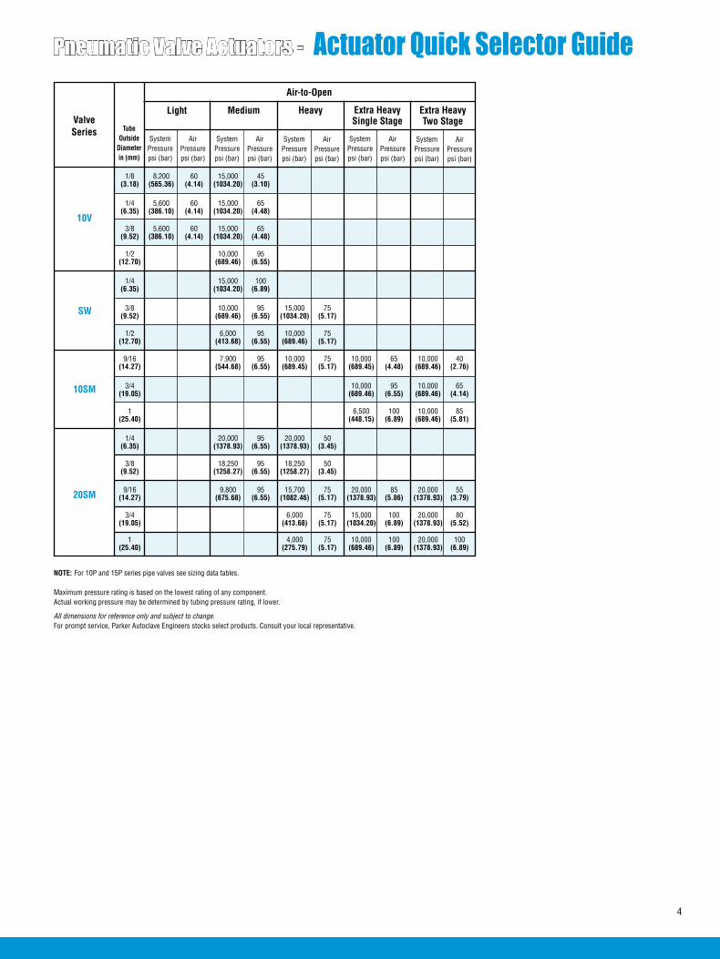
ValveSeries
Air-to-Open
Light Medium Heavy Extra HeavySingle Stage
Extra HeavyTwo Stage
SystemPressurepsi (bar)
AirPressurepsi (bar)
SystemPressurepsi (bar)
AirPressurepsi (bar)
SystemPressurepsi (bar)
AirPressurepsi (bar)
SystemPressurepsi (bar)
AirPressurepsi (bar)
SystemPressurepsi (bar)
AirPressurepsi (bar)
Tube Outside
Diameter in (mm)
10V
SW
10SM
Pneumatic Valve Actuators - Actuator Quick Selector Guide
4
20SM
NOTE: For 10P and 15P series pipe valves see sizing data tables. Maximum pressure rating is based on the lowest rating of any component. Actual working pressure may be determined by tubing pressure rating, if lower.
All dimensions for reference only and subject to change.For prompt service, Parker Autoclave Engineers stocks select products. Consult your local representative.
1/8 8,200 60 15,000 45 (3.18) (565.36) (4.14) (1034.20) (3.10)
1/4 5,600 60 15,000 65 (6.35) (386.10) (4.14) (1034.20) (4.48)
3/8 5,600 60 15,000 65 (9.52) (386.10) (4.14) (1034.20) (4.48)
1/2 10,000 95 (12.70) (689.46) (6.55)
1/4 15,000 100 (6.35) (1034.20) (6.89)
3/8 10,000 95 15,000 75 (9.52) (689.46) (6.55) (1034.20) (5.17)
1/2 6,000 95 10,000 75 (12.70) (413.68) (6.55) (689.46) (5.17)
9/16 7,900 95 10,000 75 10,000 65 10,000 40 (14.27) (544.68) (6.55) (689.45) (5.17) (689.45) (4.48) (689.46) (2.76)
3/4 10,000 95 10,000 65 (19.05) (689.46) (6.55) (689.46) (4.14)
1 6,500 100 10,000 85 (25.40) (448.15) (6.89) (689.46) (5.81)
1/4 20,000 95 20,000 50 (6.35) (1378.93) (6.55) (1378.93) (3.45)
3/8 18,250 95 18,250 50 (9.52) (1258.27) (6.55) (1258.27) (3.45)
9/16 9,800 95 15,700 75 20,000 85 20,000 55 (14.27) (675.68) (6.55) (1082.46) (5.17) (1378.93) (5.86) (1378.93) (3.79)
3/4 6,000 75 15,000 100 20,000 80 (19.05) (413.68) (5.17) (1034.20) (6.89) (1378.93) (5.52)
1 4,000 75 10,000 100 20,000 100 (25.40) (275.79) (5.17) (689.46) (6.89) (1378.93) (6.89)

ValveSeries
Air-to-Close Air-to-Open
Light Medium Heavy Extra HeavyTwo Stage
Light Medium Heavy Extra HeavyTwo Stage
SystemPressurepsi (bar)
AirPressurepsi (bar)
SystemPressurepsi (bar)
AirPressurepsi (bar)
SystemPressurepsi (bar)
AirPressurepsi (bar)
SystemPressurepsi (bar)
AirPressurepsi (bar)
SystemPressurepsi (bar)
AirPressurepsi (bar)
SystemPressurepsi (bar)
AirPressurepsi (bar)
SystemPressurepsi (bar)
AirPressurepsi (bar)
SystemPressurepsi (bar)
AirPressurepsi (bar)
Tube Outside
Diameter in (mm)
30VM
40VM
60VM
100VM
150V
1/4 30,000 50 30,000 30 30,000 75 30,000 40 (6.35) (2068.39) (3.45) (2068.39) (2.07) (2068.39) (5.17) (2068.39) (2.76) 3/8 30,000 75 30,000 40 30,000 95 30,000 50 (9.52) (2068.39) (5.17) (2068.39) (2.76) (2068.39) (6.55) (2068.39) (3.45) 9/16 30,000 75 30,000 40 30,000 95 30,000 50 (14.27) (2068.39) (5.17) (2068.39) (2.76) (2068.39) (6.55) (2068.39) (3.45) 9/16 40,000 45 40,000 55 (14.27) (2757.86) (3.10) (2757.86) (3.79) 1/4 60,000 75 60,000 40 60,000 95 60,000 50 (6.35) (4136.79) (5.17) (4136.79) (2.76) (4136.79) (6.55) (4136.79) (3.45) 3/8 60,000 75 60,000 40 60,000 95 60,000 50 (9.52) (4136.79) (5.17) (4136.79) (2.76) (4136.79) (6.55) (4136.79) (3.45) 9/16 60,000 90 60,000 45 60,000 95 60,000 50 (14.27) (4136.79) (6.21) (4136.79) (3.10) (4136.79) (6.55) (4136.79) (3.45)
5/16 100,000 100 100,000 50 100,000 70 (7.92) (6894.55) (6.89) (6894.65) (3.45) (6894.65) (4.83) 5/16 150,000 80 150,000 75 (7.92) (10341.97) (5.52) (10341.97) (5.17)
MVE
MV
1/16 15,000 100 (1.57) (1034.20) (6.89)
Air-to-Open
Mini-Light
1/8 15,000 100 (3.18) (1034.20) (6.89)
MVE/MV Mini Valves Series
Mini-Light
Air-to-Close
15,000 75 (1034.20) (5.17)
15,000 75 (1034.20) (5.17)
Pneumatic Valve Actuators - Actuator Quick Selector Guide
Maximum pressure rating is based on the lowest rating of any component. Actual working pressure may be determined by tubing pressure rating, if lower.
All dimensions for reference only and subject to change.For prompt service, Parker Autoclave Engineers stocks select products. Consult your local representative.
Tube Outside
Diameter in (mm)
ValveSeries
5
30SC 1 30,000 80 30,000 80 (25.40) (2068.39) (5.52) (2068.39) (5.52)
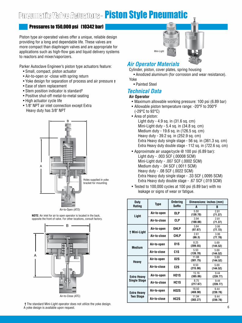
Pneumatic Valve Actuators - Piston Style Pneumatic Pressures to 150,000 psi (10342 bar)
Piston type air-operated valves offer a unique, reliable design providing for a long and dependable life. These valves are more compact than diaphragm valves and are appropriate for applications such as high-flow gas and liquid delivery systems to reactors and mixer/vaporizers.
Parker Autoclave Engineer’s piston type actuators feature: • Small, compact, piston actuator • Air-to-open or -close with spring return • Yoke design for separation of process and air pressure † • Ease of stem replacement • Stem position indicator is standard† • Positive shut-off metal-to-metal seating • High actuator cycle life • 1/8" NPT air inlet connection except Extra Heavy duty has 3/8" NPT
Duty Rating
TypeOrdering
Suffix
Light
† Mini-Light
Air Operator Materials Cylinder, piston, cover plates, spring housing • Anodized aluminum (for corrosion and wear resistance). Yoke • Painted Steel
Technical Data Air Operator • Maximum allowable working pressure: 100 psi (6.89 bar) • Allowable piston temperature range: -20°F to 200°F (-29°C to 93°C) • Area of piston: Light duty - 4.9 sq. in (31.6 sq. cm) Mini-Light duty - 5.4 sq. in (34.8 sq. cm) Medium duty - 19.6 sq. in (126.5 sq. cm) Heavy duty - 39.2 sq. in (252.9 sq. cm) Extra Heavy duty single stage - 56 sq. in (361.3 sq. cm) Extra Heavy duty double stage - 112 sq. in (722.6 sq. cm) • Approximate air usage/cycle @ 100 psi (6.89 bar): Light duty - .003 SCF (.00008 SCM) Mini-Light duty - .007 SCF (.0002 SCM) Medium duty - .04 SCF (.0011 SCM) Heavy duty - .08 SCF (.0022 SCM) Extra Heavy duty single stage - .33 SCF (.0095 SCM) Extra Heavy duty double stage - .67 SCF (.019 SCM) • Tested to 100,000 cycles at 100 psi (6.89 bar) with no leakage or signs of wear or fatigue.
Dimensions: inches (mm)A B
Air-to-open OLP5.50
(139.70)2.81
(71.37)
Air-to-close CLP 3.94(100.08)
2.81(71.37)
Air-to-open OHLP3.84
(97.67)3.06
(77.72)
Medium
Heavy
Extra HeavyTwo Stage
Air-to-open O2S11.88
(301.75)5.69
(144.52)
Air-to-close HC2S11.94
(303.27)9.44
(239.78)
Air-to-open O1S 8.25(209.55)
5.69(144.52)
Air-to-close C1S 5.50(139.70)
5.69(144.52)
Air-to-close C2S8.50
(215.90)5.69
(144.52)
Air-to-open HO2S 18.50(469.90)
9.44(239.78)
Mini-Light
† The standard Mini-Light operator does not utilize the yoke design. A yoke design is available upon request.
Air-to-Open (ATO)
Air-to-Close (ATC)
Air-to-close CHLP 2.61(66.3)
3.06(77.70)
Extra HeavySingle Stage
Air-to-open HO1S15.16
(385.06)9.44
(239.77)
Air-to-close HC1S 8.75(217.67)
9.44(239.77)
A
B
Air-to-Open (ATO)
6
A
B
Air-to-Close (ATC)
Holes supplied in yoke bracket for mounting
NOTE: Air inlet for air to open operator is located in the back, opposite the front of valve. For other locations, consult factory.

7
Pneumatic Valve Actuators - Diaphragm Style Pneumatic Pressures to 150,000 psi (10342 bar)
Diaphragm type air-operated valves are an efficient and eco-nomical means for “remote on-off” control of a wide range of process requirements. Diaphragm type actuators are designed to provide a dependable alternative to piston type actuators.
Parker Autoclave Engineer’s diaphragm type air actuators feature: • Economical diaphragm design • Air-to-open or -close with spring return • Integral connection of valve and operator for height resticted applications. • Oversized weep holes for separation of process and air operator pressures. • Stem position indicator optional • Medium actuator cycle life • 1/8" NPT air inlet connection
Duty Rating
TypeOrdering
Suffix
Light
Medium
Heavy
Air-to-open
Air-to-close
Air-to-open
Air-to-close
Air-to-open
Air-to-close
Air Operator Materials Upper and lower housing, spring housing • Anodized aluminum† Diaphragm plate • Cast ductile iron.
Technical Data Air Operator • Maximum allowable working pressure: 100 psi (6.89 bar) • Allowable diaphragm temperature range: -40°F to 200°F (-40°C to 93°C) • Area of diaphragm: Light duty - 4.9 sq. in (31.6 sq. cm) Medium duty - 19.6 sq. in (126.5 sq. cm) Heavy duty - 45.66 sq. in (294.58 sq. cm) • Approximate air usage/cycle @ 100 psi (6.89 bar): Light duty - .007 SCF (.00019 SCM) Medium duty - .07 SCF (.0019 SCM) Heavy duty - .2 SCF (.0056 SCM)
Dimensions: inches (mm)
A B
OL
CL
OM
CM
OH
CH
5.00(127.00)
4.25(107.95)
2.38(60.45)
4.25(107.95)
6.42(163.01)
7.12(180.90)
3.75(95.25)
7.12(180.90)
8.75(222.25)
10.00(254.00)
4.69(119.13)
10.00(254.00)
A
B
Air-to-Open (ATO)
A
B
Air-to-Close (ATC)
†Note: OH and CH are carbon steel painted

ValveSeries Operator Duty
Pneumatic Valve Actuators - Air Operator Sizing DataAir-to-Close
Medium Duty
AirPressurepsi (bar)
System Pressure KSI (Mpa)Maximum Pressure psi (bar)*
Stem Travel in (mm)
FlowCoefficient**
10V2
1-4 6 8 10 12 14 15 (6.89-27.57) (41.37) (55.16) (68.95) (82.74) (96.53) (103.42)
30 40 55 65 85 95 100 15,000 0.16 0.12 (2.07) (2.76) (3.79) (4.48) (5.86) (6.55) (6.89) (1034.20) (4.06)
25 25 25 25 25 25 30 (1.72) (1.72) (1.72) (1.72) (1.72) (1.72) (2.07)
Light Duty
Medium Duty10V4
Light Duty 40 60 75 95 10,000 0.19 0.20 (2.76) (4.13) (5.17) (6.55) (689.46) (4.83)
30 30 30 30 35 35 40 15,000 (2.07) (2.07) (2.07) (2.07) (2.41) (2.41) (2.76) (1034.20)
Medium Duty10V6
Light Duty 40 60 75 100 10,000 0.19 0.20 (2.76) (4.13) (5.17) (6.89) (689.46) (4.83)
30 30 30 35 35 35 40 15,000 (2.07) (2.07) (2.07) (2.41) (2.41) (2.41) (2.76) (1034.20)
Medium Duty
10V8 Medium Duty 50 50 55 65 10,000 0.31 0.86 (3.45) (3.45) (3.79) (4.48) (689.46) (7.90)
40 40 40 50 55 60 65 15,000 0.25 0.65 (2.76) (2.76) (2.76) (3.45) (3.79) (4.13) (4.48) (1034.20) (6.40)
Medium Duty
SW6Medium Duty
50 50 55 70 75 85 90 15,000 0.25 0.95 (3.45) (3.45) (3.79) (4.83) (5.17) (5.86) (6.21) (1034.20) (6.40)
65 70 100 8,000 0.38 1.90 (4.48) (4.83) (6.89) (551.57) (9.70)
Heavy DutySW8
35 35 50 60 10,000 (2.41) (2.41) (3.45) (4.13) (698.46)
SW4
Series 10V and SW Valves
Heavy Duty 20 25 30 35 40 45 50 15,000 (1.38) (1.72) (2.07) (2.41) (2.76) (3.10) (3.45) (1034.20)
8
AirPressurepsi (bar)
Heavy Duty
10SM12
Medium Duty 90 100 4,800 0.44 2.80 (6.21) (6.89) (330.94) (11.18)
45 45 60 80 100 10,000 (3.10) (3.10) (4.13) (5.52) (6.89) (689.46)
35 35 50 60 70 10,000 (2.41) (2.41) (3.45) (4.13) (4.83) (689.46)
Heavy Duty
10SM16
Medium Duty 100 2,800 0.56 5.20 (6.89) (193.05) (14.22)
60 70 100 6,300 (4.13) (4.83) (6.89) (434.36)
Extra Heavy Duty
Single Stage 25 25 35 45 55 10,000 (1.72) (1.72) (2.41) (3.10) (3.79) (689.46)
Extra Heavy DutySingle Stage
ValveSeries Operator Duty System Pressure KSI (Mpa)
Maximum Pressure psi (bar)*
Stem Travel in (mm)
FlowCoefficient**
1-3 4 6 8 10 12 14 16 18 20 (6.89-20.68) (27.58) (41.37) (55.16) (68.95) (82.74) (96.53) (110.31) (124.10) (137.89)
Heavy Duty
10SM9
Medium Duty 65 65 75 100 8,600 0.38 1.75 (4.48) (4.48) (5.17) (6.89) (592.94) (9.65)
35 35 40 50 55 10,000 (2.41) (2.41) (2.76) (3.45) (3.79) (689.46)
Extra Heavy DutySingle Stage
30 30 30 35 45 10,000 (2.07) (2.07) (2.07) (2.41) (3.10) (689.46)
Extra Heavy DutyTwo Stage
15 15 15 20 20 10,000 (1.03) (1.03) (1.03) (1.38) (1.38) (689.46)
Extra Heavy DutyTwo Stage
Extra Heavy DutyTwo Stage
45 50 70 95 8,500 (3.10) (3.45) (4.83) (6.55) (586.46)
20 20 25 30 35 10,000 (1.38) (1.38) (1.72) (2.07) (2.41) (689.46)
Series 10SM Valves

9
ValveSeries Operator Duty
Heavy Duty
AirPressurepsi (bar)
System Pressure KSI (Mpa)Maximum Pressure psi (bar)*
Stem Travel in (mm)
FlowCoefficient**
20SM415P4†
1-3 4 6 8 10 12 14 16 18 20 (6.89-20.68) (27.58) (41.37) (55.16) (68.95) (82.74) (96.53) (110.31) (124.10) (137.89)
40 40 40 40 50 60 70 80 85 95 20,000 0.25 0.31 (2.76) (2.76) (2.76) (2.76) (3.45) (4.13) (4.83) (5.52) (5.86) (6.55) (1378.93) (6.35) Medium Duty
Heavy Duty
20SM615P6†
Medium Duty
Heavy Duty
20SM915P8†
Medium Duty 60 60 65 80 100 10,700 0.38 1.30 (4.13) (4.13) (4.48) (5.52) (6.89) (737.73) (9.65)
30 30 30 40 50 55 60 70 80 85 20,000 (2.07) (2.07) (2.07) (2.76) (3.45) (3.79) (4.13) (4.83) (5.52) (5.86) (1378.93)
Extra Heavy Duty
Single Stage
25 25 25 30 35 45 50 55 60 65 20,000 (1.72) (1.72) (1.72) (2.07) (2.41) (3.10) (3.45) (3.79) (4.13) (4.48) (1378.93)
Series 20SM Valves
45 45 45 45 55 65 75 85 95 100 19,000 0.25 0.75 (3.10) (3.10) (3.10) (3.10) (3.79) (4.48) (5.17) (5.86) (6.55) (6.89) (1309.98) (6.35)
25 25 25 25 30 35 40 45 50 55 20,000 (1.72) (1.72) (1.72) (1.72) (2.07) (2.41) (2.76) (3.10) (3.45) (3.79) (1378.93)
20SM1610P16†
Heavy Duty
Medium Duty 80 80 100 6,100 0.44 2.50 (5.44) (5.44) (6.80) (420.57) (11.18)
40 40 50 60 75 90 100 13,600 (2.72) (2.72) (3.40) (4.08) (5.10) (6.12) (6.80) (937.67)
15 15 20 25 30 35 40 45 50 50 20,000 (1.03) (1.03) (1.38) (1.72) (2.07) (2.41) (2.76) (3.10) (3.45) (3.45) (1378.93)
Heavy Duty
Medium Duty 100 100 3,900 0.56 3.40 (6.89) (6.89) (268.89) (14.22)
50 50 70 100 8,800 (3.45) (3.45) (4.83) (6.89) (606.73)
40 40 55 70 85 100 12,500 (2.76) (2.76) (3.79) (4.83) (5.86) (6.89) (861.83)
Extra Heavy Duty
Single Stage
Air-to-Close -
15 15 15 15 20 20 25 25 30 30 20,000 (1.03) (1.03) (1.03) (1.03) (1.38) (1.38) (1.72) (1.72) (2.07) (2.07) (1378.93)
Extra Heavy DutyTwo Stage
20 20 20 20 25 30 35 40 45 50 (1.38) (1.38) (1.38) (1.38) (1.72) (2.07) (2.41) (2.76) (3.10) (3.45)
30 30 40 50 60 65 75 85 95 100 19,000 (2.07) (2.07) (2.76) (3.45) (4.13) (4.48) (5.17) (5.86) (6.55) (6.89) (1310.00)
Extra Heavy DutyTwo Stage
Extra Heavy Duty
Single Stage
AirPressurepsi (bar)
30SC16
ValveSeries Operator Duty System Pressure KSI (Mpa)
Maximum Pressure psi (bar)*
Stem Travel in (mm)
FlowCoefficient**
1-10 15 16 18 20 22 24 26 28 30 (6.89-68.94) (103.42) (110.31) (124.10) (137.89) (151.68) (165.47) (179.26) (193.05) (206.84)
Series 30SC Valves
Extra Heavy DutyTwo Stage
30 40 45 50 55 60 65 70 75 80 30,000 0.50 2.61 (2.07) (2.76) (3.10) (3.45) (3.79) (4.13) (4.48) (4.83) (5.17) (5.52) (2068.39) (12.70)
Extra Heavy DutyTwo Stage
20 20 25 35 40 50 55 60 70 75 20,000 (1.38) (1.38) (1.72) (2.41) (2.76) (3.45) (3.79) (4.48) (4.83) (5.17) (1378.93)
20SM1210P12†
** Cv data is for 2-way straight valves.For angle pattern, add approximately 50% to the CV valve.
CAUTION: While testing has shown O-rings to provide satisfactory service life, both cyclic and shelf life may vary widely with differing service conditions, properties of reactants, pressure and temperature cycling and age of the O-ring, FREQUENT INSPECTIONS SHOULD BE MADE to detect any deterioration, and O-rings replaced as required.
*Maximum pressure rating is based on the lowest rating of any component. Actual working pressure may be determined by tubing pressure rating, if lower.
All dimensions for reference only and subject to change.For prompt service, Parker Autoclave Engineers stocks select products. Consult your local representative.
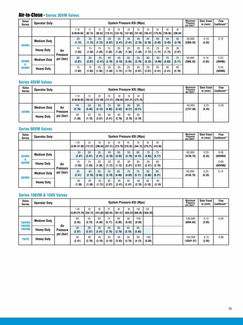
10
ValveSeries Operator Duty
Heavy Duty
System Pressure KSI (Mpa)Maximum Pressure psi (bar)*
Stem Travel in (mm)
FlowCoefficient**
30VM4
1-10 12 14 16 18 20 22 24 26 28 30 (6.89-68.94) (82.74) (96.53) (110.31) (124.10) (137.89) (151.68) (165.47) (179.26) (193.05) (206.84)
25 25 25 30 35 35 40 45 50 50 55 30,000 0.19 0.12 (1.72) (1.72) (1.72) (2.07) (2.41) (2.41) (2.76) (3.10) (3.45) (3.45) (3.79) (2068.39) (4.83)
15 15 15 15 20 20 20 25 25 25 30 (1.03) (1.03) (1.03) (1.03) (1.38) (1.38) (1.38) (1.72) (1.72) (1.72) (2.07)
Medium Duty
Heavy Duty
30VM6 &
30VM9
Medium Duty
Air-to-Close - Series 30VM Valves
30 30 35 40 45 50 55 60 65 70 75 30,000 0.19 0.23 (2.07) (2.07) (2.41) (2.76) (3.10) (3.45) (3.79) (4.13) (4.48) (4.83) (5.17) (2068.39) (4.83) (30VM6)
15 15 20 20 25 25 30 30 35 35 40 0.33 (1.03) (1.03) (1.38) (1.38) (1.72) (1.72) (2.07) (2.07) (2.41) (2.41) (2.76) (30VM9)
AirPressurepsi (bar)
ValveSeries Operator Duty
Heavy Duty
System Pressure KSI (Mpa)Maximum Pressure psi (bar)*
Stem Travel in (mm)
FlowCoefficient**
40VM9
1-10 15 20 25 30 35 40 ( 6.89-68.94) (103.42) (137.89) (172.37) (206.84) (241.31) (275.79)
40 50 60 70 80 90 90 40,000 0.25 0.28 (2.76) (3.45) (4.13) (4.83) (5.52) (6.21) (6.21) (2757.86) (6.35)
20 25 30 35 40 45 45 (1.38) (1.70) (2.07) (2.41) (2.76) (3.10) (3.10)
Medium Duty
Series 40VM Valves
AirPressurepsi (bar)
ValveSeries Operator Duty
Heavy Duty
System Pressure KSI (Mpa)Maximum Pressure psi (bar)*
Stem Travel in (mm)
FlowCoefficient**
60VM4&
60VM6
1-20 25 30 35 40 45 50 55 60 (6.89-137.89) (172.37) (206.84) (241.31) (275.79) (310.26) (344.73) (379.21) (413.68)
30 30 35 45 50 55 60 70 75 60,000 0.25 0.08 (2.07) (2.07) (2.41) (3.10) (3.45) (3.79) (4.13) (4.83) (5.17) (4136.79) (6.35) (60VM4)
15 15 20 25 25 30 30 35 40 0.09 (1.03) (1.03) (1.38) (1.72) (1.72) (2.07) (2.07) (2.41) (2.76) (60VM6)
Medium Duty
Heavy Duty60VM9
Medium Duty
Series 60VM Valves
35 40 50 55 65 70 75 85 90 60,000 0.25 0.14 (2.41) (2.76) (3.45) (3.79) (4.48) (4.83) (5.17) (5.86) (6.21) (4136.79) (6.35)
20 20 25 30 35 35 40 45 45 (1.38) (1.38) (1.72) (2.07) (2.41) (2.41) (2.76) (3.10) (3.10)
AirPressurepsi (bar)
ValveSeries Operator Duty
Heavy Duty
System Pressure KSI (Mpa)Maximum Pressure psi (bar)*
Stem Travel in (mm)
FlowCoefficient**
100VM4100VM5100VM6
1-40 50 60 70 80 90 100 150 (6.89-275.79) (344.73) (413.68) (482.63) (551.57) (620.52) (689.46) (1034.20)
50 55 65 75 85 95 100 100,000 0.12 0.09 (3.45) (3.79) (4.48) (5.17) (5.86) (6.55) (6.89) (6894.65) (3.05)
30 30 35 40 40 45 50 (2.07) (2.07) (2.41) (2.76) (2.76) (3.10) (3.45)
Medium Duty
Series 100VM & 150V Valves
AirPressurepsi (bar)
Heavy Duty 35 40 45 45 50 55 60 100 150,000 0.12 0.06 (2.41) (2.76) (3.10) (3.10) (3.45) (3.79) (4.13) (6.89) (10341.97) (3.05)
150V5
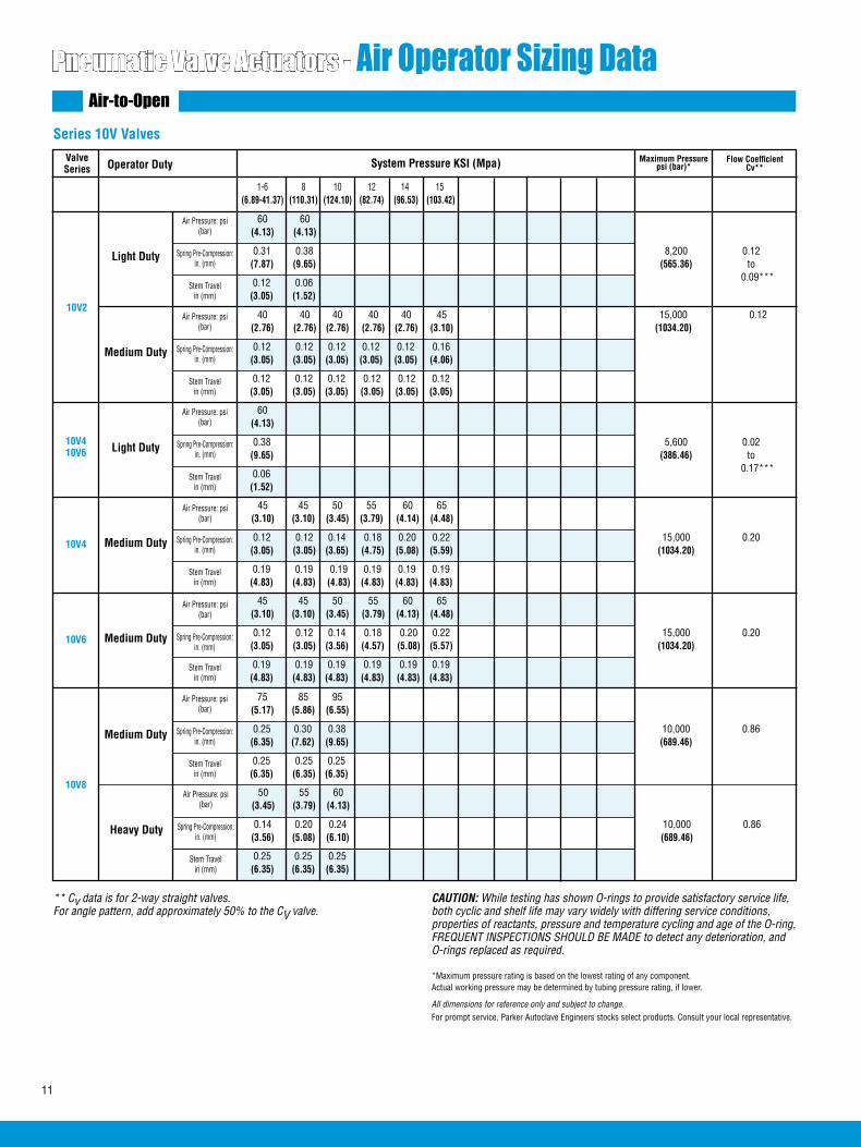
11
Pneumatic Valve Actuators - Air Operator Sizing DataAir-to-Open
ValveSeries Operator Duty System Pressure KSI (Mpa)
10V2
1-6 8 10 12 14 15 (6.89-41.37) (110.31) (124.10) (82.74) (96.53) (103.42)
60 60 (4.13) (4.13)
Light Duty
Series 10V Valves
0.12 0.06 (3.05) (1.52)
Air Pressure: psi (bar)
Spring Pre-Compression:in. (mm)
Stem Travel in (mm)
Maximum Pressure psi (bar)*
Flow Coefficient Cv**
40 40 40 40 40 45 15,000 0.12 (2.76) (2.76) (2.76) (2.76) (2.76) (3.10) (1034.20)
Medium Duty 0.12 0.12 0.12 0.12 0.12 0.16 (3.05) (3.05) (3.05) (3.05) (3.05) (4.06)
0.12 0.12 0.12 0.12 0.12 0.12 (3.05) (3.05) (3.05) (3.05) (3.05) (3.05)
Air Pressure: psi (bar)
Spring Pre-Compression:in. (mm)
Stem Travel in (mm)
10V4 10V6
60 (4.13)
Light Duty
0.06 (1.52)
Air Pressure: psi (bar)
Stem Travel in (mm)
10V4
45 45 50 55 60 65 (3.10) (3.10) (3.45) (3.79) (4.14) (4.48)
Medium Duty
0.19 0.19 0.19 0.19 0.19 0.19 (4.83) (4.83) (4.83) (4.83) (4.83) (4.83)
Air Pressure: psi (bar)
Spring Pre-Compression:in. (mm)
Stem Travel in (mm)
10V6
45 45 50 55 60 65 (3.10) (3.10) (3.45) (3.79) (4.13) (4.48)
Medium Duty 0.12 0.12 0.14 0.18 0.20 0.22 15,000 0.20 (3.05) (3.05) (3.56) (4.57) (5.08) (5.57) (1034.20)
0.19 0.19 0.19 0.19 0.19 0.19 (4.83) (4.83) (4.83) (4.83) (4.83) (4.83)
Air Pressure: psi (bar)
Stem Travel in (mm)
10V8
75 85 95 (5.17) (5.86) (6.55)
Medium Duty 0.25 0.30 0.38 10,000 0.86 (6.35) (7.62) (9.65) (689.46) 0.25 0.25 0.25 (6.35) (6.35) (6.35)
Air Pressure: psi (bar)
Spring Pre-Compression:in. (mm)
Stem Travel in (mm)
Spring Pre-Compression:in. (mm)
Spring Pre-Compression:in. (mm)
0.38 5,600 0.02 (9.65) (386.46) to 0.17***
0.31 0.38 8,200 0.12 (7.87) (9.65) (565.36) to 0.09***
50 55 60 (3.45) (3.79) (4.13)
Heavy Duty 0.14 0.20 0.24 10,000 0.86 (3.56) (5.08) (6.10) (689.46) 0.25 0.25 0.25 (6.35) (6.35) (6.35)
Air Pressure: psi (bar)
Spring Pre-Compression:in. (mm)
Stem Travel in (mm)
0.12 0.12 0.14 0.18 0.20 0.22 15,000 0.20 (3.05) (3.05) (3.65) (4.75) (5.08) (5.59) (1034.20)
** Cv data is for 2-way straight valves.For angle pattern, add approximately 50% to the CV valve.
CAUTION: While testing has shown O-rings to provide satisfactory service life, both cyclic and shelf life may vary widely with differing service conditions, properties of reactants, pressure and temperature cycling and age of the O-ring, FREQUENT INSPECTIONS SHOULD BE MADE to detect any deterioration, and O-rings replaced as required.
*Maximum pressure rating is based on the lowest rating of any component. Actual working pressure may be determined by tubing pressure rating, if lower.
All dimensions for reference only and subject to change.For prompt service, Parker Autoclave Engineers stocks select products. Consult your local representative.
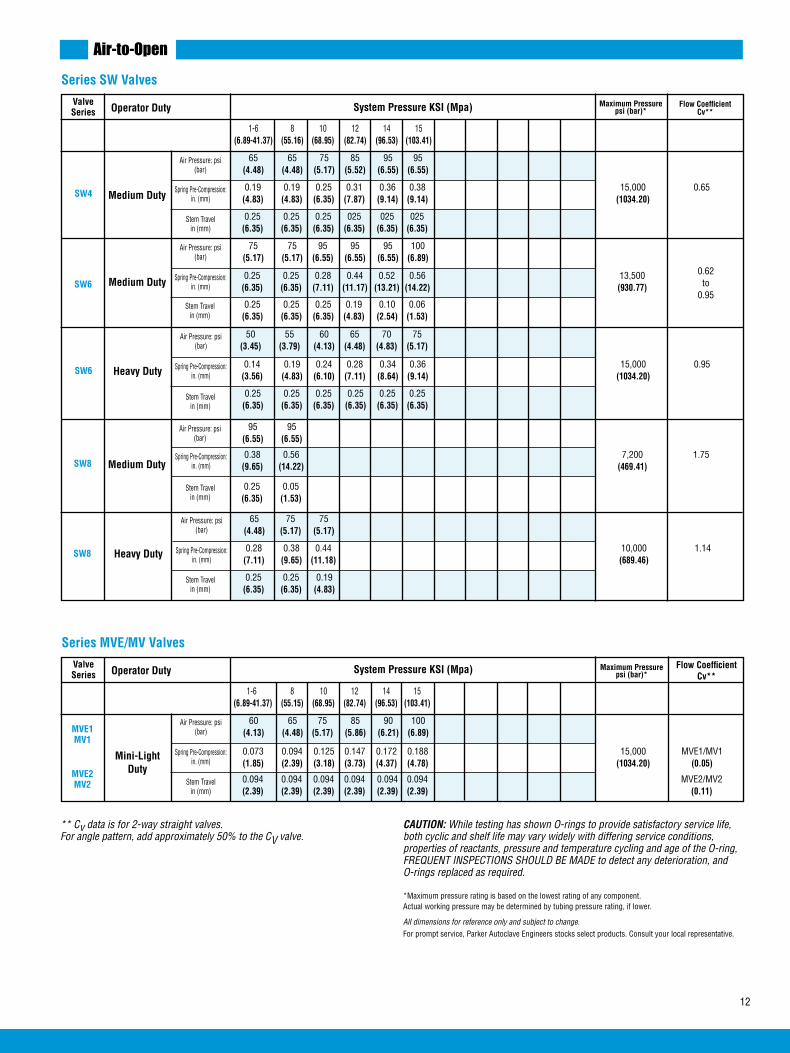
12
Spring Pre-Compression:in. (mm)
ValveSeries Operator Duty System Pressure KSI (Mpa)
SW4
1-6 8 10 12 14 15 (6.89-41.37) (55.16) (68.95) (82.74) (96.53) (103.41)
65 65 75 85 95 95 (4.48) (4.48) (5.17) (5.52) (6.55) (6.55)
Medium Duty
Series SW Valves
0.19 0.19 0.25 0.31 0.36 0.38 15,000 0.65 (4.83) (4.83) (6.35) (7.87) (9.14) (9.14) (1034.20)
0.25 0.25 0.25 025 025 025 (6.35) (6.35) (6.35) (6.35) (6.35) (6.35)
Air Pressure: psi (bar)
Spring Pre-Compression:in. (mm)
Stem Travel in (mm)
75 75 95 95 95 100 (5.17) (5.17) (6.55) (6.55) (6.55) (6.89)
Medium Duty 0.25 0.25 0.28 0.44 0.52 0.56 13,500 (6.35) (6.35) (7.11) (11.17) (13.21) (14.22) (930.77)
0.25 0.25 0.25 0.19 0.10 0.06 (6.35) (6.35) (6.35) (4.83) (2.54) (1.53)
Air Pressure: psi (bar)
Spring Pre-Compression:in. (mm)
Stem Travel in (mm)
SW6
** Cv data is for 2-way straight valves.For angle pattern, add approximately 50% to the CV valve.
CAUTION: While testing has shown O-rings to provide satisfactory service life, both cyclic and shelf life may vary widely with differing service conditions, properties of reactants, pressure and temperature cycling and age of the O-ring, FREQUENT INSPECTIONS SHOULD BE MADE to detect any deterioration, and O-rings replaced as required.
*Maximum pressure rating is based on the lowest rating of any component. Actual working pressure may be determined by tubing pressure rating, if lower.
All dimensions for reference only and subject to change.For prompt service, Parker Autoclave Engineers stocks select products. Consult your local representative.
ValveSeries Operator Duty System Pressure KSI (Mpa) Maximum Pressure
psi (bar)*
MVE1MV1
1-6 8 10 12 14 15 (6.89-41.37) (55.15) (68.95) (82.74) (96.53) (103.41)
60 65 75 85 90 100 (4.13) (4.48) (5.17) (5.86) (6.21) (6.89)
Mini-Light Duty
Series MVE/MV Valves
0.073 0.094 0.125 0.147 0.172 0.188 15,000 MVE1/MV1 (1.85) (2.39) (3.18) (3.73) (4.37) (4.78) (1034.20) (0.05)
0.094 0.094 0.094 0.094 0.094 0.094 MVE2/MV2 (2.39) (2.39) (2.39) (2.39) (2.39) (2.39) (0.11)
Air Pressure: psi (bar)
Spring Pre-Compression:in. (mm)
Stem Travel in (mm)
Flow Coefficient Cv**
MVE2MV2
Air-to-Open
50 55 60 65 70 75 (3.45) (3.79) (4.13) (4.48) (4.83) (5.17)
Heavy Duty 0.14 0.19 0.24 0.28 0.34 0.36 15,000 0.95 (3.56) (4.83) (6.10) (7.11) (8.64) (9.14) (1034.20)
0.25 0.25 0.25 0.25 0.25 0.25 (6.35) (6.35) (6.35) (6.35) (6.35) (6.35)
Air Pressure: psi (bar)
Spring Pre-Compression:in. (mm)
Stem Travel in (mm)
SW6
95 95 (6.55) (6.55)
Medium Duty 0.38 0.56 7,200 1.75 (9.65) (14.22) (469.41) 0.25 0.05 (6.35) (1.53)
Air Pressure: psi (bar)
Stem Travel in (mm)
SW8
65 75 75 (4.48) (5.17) (5.17)
Heavy Duty 0.28 0.38 0.44 10,000 1.14 (7.11) (9.65) (11.18) (689.46)
0.25 0.25 0.19 (6.35) (6.35) (4.83)
Air Pressure: psi (bar)
Spring Pre-Compression:in. (mm)
Stem Travel in (mm)
SW8
Maximum Pressure psi (bar)*
Flow Coefficient Cv**
0.62to
0.95
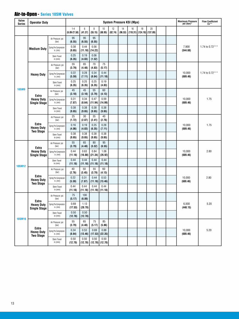
13
ValveSeries Operator Duty System Pressure KSI (Mpa)
10SM9
1-4 6 8 10 12 14 16 18 20 (6.89-27.58) (41.37) (55.15) (68.95) (82.74) (96.53) (110.31) (124.10) (137.89)
95 95 95 (6.55) (6.55) (6.55)
0.38 0.44 0.56 7,900 1.74 to 0.72*** (9.65) (11.18) (14.22) (544.68)
0.25 0.19 0.06 (6.35) (4.83) (1.52)
55 65 70 75 (3.79) (4.48) (4.83) (5.17)
0.22 0.28 0.34 0.44 10,000 1.74 to 0.72*** (5.59) (7.11) (8.64) (11.18) (689.46)
0.25 0.25 0.25 0.19 (6.35) (6.35) (6.35) (4.83)
45 45 55 60 (3.10) (3.10) (3.79) (4.13)
0.31 0.34 0.47 0.59 10,000 1.75 (7.87) (8.64) (11.94) (14.99) (689.46)
0.38 0.38 0.38 0.38 (9.65) (9.65) (9.65) (9.65)
25 30 35 40 (1.72) (2.07) (2.41) (2.76)
0.16 0.19 0.25 0.28 10,000 1.75 (4.06) (4.83) (6.35) (7.11) (689.46)
0.38 0.38 0.38 0.38 (9.65) (9.65) (9.65) (9.65)
Series 10SM Valves
10SM12
Air-to-Open -
Medium Duty
Air Pressure: psi (bar)
Spring Pre-Compression:in. (mm)
Stem Travel in (mm)
Heavy Duty
Air Pressure: psi (bar)
Spring Pre-Compression:in. (mm)
Stem Travel in (mm)
Air Pressure: psi (bar)
Spring Pre-Compression:in. (mm)
Stem Travel in (mm)
Extra Heavy DutyTwo Stage
Air Pressure: psi (bar)
Spring Pre-Compression:in. (mm)
Stem Travel in (mm)
Extra Heavy Duty
Single Stage
Air Pressure: psi (bar)
Spring Pre-Compression:in. (mm)
Stem Travel in (mm)
Extra Heavy DutyTwo Stage
Air Pressure: psi (bar)
Spring Pre-Compression:in. (mm)
Stem Travel in (mm)
Extra Heavy Duty
Single Stage
40 50 55 60 (2.76) (3.45) (3.79) (4.13)
0.22 0.31 0.44 0.53 10,000 2.80 (5.59) (7.87) (11.18) (13.46) (689.46)
0.44 0.44 0.44 0.44 (11.18) (11.18) (11.18) (11.18)
55 65 80 95 (3.79) (4.48) (5.52) (6.55)
0.44 0.63 0.84 1.06 10,000 2.80 (11.18) (16.00) (21.34) (26.92) (689.46)
0.44 0.44 0.44 0.44 (11.18) (11.18) (11.18) (11.18)
Air Pressure: psi (bar)
Spring Pre-Compression:in. (mm)
Stem Travel in (mm)
Extra Heavy DutyTwo Stage
Air Pressure: psi (bar)
Spring Pre-Compression:in. (mm)
Stem Travel in (mm)
Extra Heavy Duty
Single Stage
55 65 75 85 (3.79) (4.48) (5.17) (5.86)
0.34 0.53 0.69 0.88 10,000 5.20 (8.64) (13.46) (17.53) (22.35) (689.46)
0.50 0.50 0.50 0.50 (12.70) (12.70) (12.70) (12.70)
75 100 (5.17) (6.89)
0.69 1.13 6,500 5.20 (17.53) (28.70) (448.15)
0.50 0.50 (12.70) (12.70)
10SM16
Maximum Pressure psi (bar)*
Flow Coefficient Cv**

14
Series 10SM Valves
Air Pressure: psi (bar)
Spring Pre-Compression:in. (mm)
Stem Travel in (mm)
Medium Duty
Air Pressure: psi (bar)
Spring Pre-Compression:in. (mm)
Stem Travel in (mm)
Heavy Duty
Air Pressure: psi (bar)
Spring Pre-Compression:in. (mm)
Stem Travel in (mm)
ExtraHeavy DutyTwo Stage
20SM915P8†
ExtraHeavy Duty
Single Stage
Air Pressure: psi (bar)
Spring Pre-Compression:in. (mm)
Stem Travel in (mm)
65 65 65 75 85 95 95 95 95 (4.48) (4.48) (4.48) (5.17) (5.86) (6.55) (6.55) (6.55) (6.55)
0.19 0.19 0.19 0.25 0.31 0.38 0.44 0.50 0.56 (4.83) (4.83) (4.83) (6.35) (7.87) (9.65) (11.18) (12.70) (14.22)
0.25 0.25 0.25 0.25 0.25 0.25 0.19 0.12 0.06 20,000 0.31 to 0.22*** (6.35) (6.35) (6.35) (6.35) (6.35) (6.35) (4.83) (3.05) (1.52) (1378.93)
35 35 35 40 45 50 50 50 50 (2.41) (2.41) (2.41) (2.76) (3.10) (3.45) (3.45) (3.45) (3.45)
Air Pressure: psi (bar)Medium Duty
Spring Pre-Compression:in. (mm)
Stem Travel in (mm)
Air Pressure: psi (bar)Heavy Duty
20SM415P4†
ValveSeries Operator Duty System Pressure KSI (Mpa)
1-4 6 8 10 12 14 16 18 20 (6.89-27.58) (41.37) (55.15) (68.95) (82.74) (96.53) (110.31) (124.10) (137.89)
Series 20SM ValvesAir-to-Open -
65 65 75 85 95 95 95 95 (4.48) (4.48) (5.17) (5.86) (6.55) (6.55) (6.55) (6.55)
0.19 0.19 0.25 0.31 0.38 0.44 0.50 0.56 (4.83) (4.83) (6.35) (7.87) (9.65) (11.18) (12.70) (14.22)
0.25 0.25 0.25 0.25 0.25 0.19 0.12 0.06 18,250 0.75 to 0.57*** (6.35) (6.35) (6.35) (6.35) (6.35) (4.83) (3.05) (1.52) (1258.27)
35 35 40 45 50 50 50 50 (2.41) (2.41) (2.76) (3.10) (3.45) (3.45) (3.45) (3.45)
Air Pressure: psi (bar)Medium Duty
Spring Pre-Compression:in. (mm)
Stem Travel in (mm)
Air Pressure: psi (bar)Heavy Duty
20SM615P6†
85 90 95 95 (5.86) (6.21) (6.55) (6.55)
0.31 0.34 0.47 0.56 9,800 1.29 to 0.53*** (7.87) (8.64) (11.94) (14.22) (675.68)
0.25 0.25 0.15 0.06 (6.35) (6.35) (3.81) (1.52)
50 55 65 70 75 75 75 (3.45) (3.79) (4.48) (4.83) (5.17) (5.17) (5.17)
0.19 0.22 0.28 0.34 0.44 0.50 0.56 15,700 1.29 to 0.53*** (4.83) (5.59) (7.11) (8.64) (11.18) (12.70) (14.22) (1082.46)
0.25 0.25 0.25 0.25 0.19 0.12 0.06 (6.35) (6.35) (6.35) (6.35) (4.83) (3.05) (1.52)
40 40 50 55 60 65 70 75 85 (2.76) (2.76) (3.45) (3.79) (4.13) (4.48) (4.83) (5.17) (5.86)
0.25 0.28 0.38 0.47 0.56 0.66 0.75 0.84 0.94 20,000 1.30 (6.35) (7.11) (9.65) (11.94) (14.22) (16.76) (19.05) (21.34) (23.88) (1378.93)
0.38 0.38 0.38 0.38 0.38 0.38 0.38 0.38 0.38 (9.65) (9.65) (9.65) (9.65) (9.65) (9.65) (9.65) (9.65) (9.65)
30 35 35 40 40 45 50 50 55 (2.07) (2.41) (2.41) (2.72) (2.72) (3.10) (3.45) (3.45) (3.79)
0.13 0.16 0.19 0.25 0.28 0.34 0.38 0.44 0.47 20,000 1.30 (3.30) (4.06) (4.83) (6.35) (7.11) (8.64) (9.65) (11.18) (11.94) (1378.93)
0.38 0.38 0.38 0.38 0.38 0.38 0.38 0.38 0.38 (9.65) (9.65) (9.65) (9.65) (9.65) (9.65) (9.65) (9.65) (9.65)
Maximum Pressure psi (bar)*
Flow Coefficient Cv**
† Maximum rating is based on the valve rating.
*** Cv varies because of spring compression limitations. The flow coefficient range is given for the maximum stem travel (lowest system pressure) to minimum travel (highest system pressure).
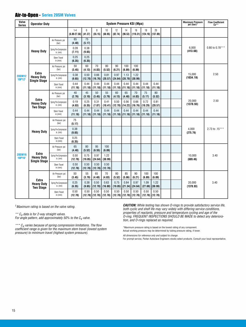
15
ValveSeries Operator Duty System Pressure KSI (Mpa)
65 75 (4.48) (5.17)
0.28 0.38 (7.11) (9.65)
0.25 0.25 (6.35) (6.35)
50 60 70 80 90 100 100 (3.45) (4.13) (4.83) (5.52) (6.21) (6.89) (6.89)
0.38 0.50 0.66 0.81 0.97 1.13 1.22 (9.65) (12.70) (16.76) (20.57) (24.64) (28.70) (30.99)
0.44 0.44 0.44 0.44 0.44 0.44 0.44 0.44 0.44 (11.18) (11.18) (11.18) (11.18) (11.18) (11.18) (11.18) (11.18) (11.18)
40 45 50 55 60 65 70 75 80 (2.76) (3.10) (3.45) (3.79) (4.13) (4.48) (4.83) (5.17) (5.52)
0.19 0.25 0.31 0.41 0.50 0.56 0.66 0.72 0.81 (4.83) (6.35) (7.87) (10.41) (12.70) (14.22) (16.76) (18.29) (20.57)
0.44 0.44 0.44 0.44 0.44 0.44 0.44 0.44 0.44 (11.18) (11.18) (11.18) (11.18) (11.18) (11.18) (11.18) (11.18) (11.18)
Air Pressure: psi (bar)
Spring Pre-Compression:in. (mm)
Stem Travel in (mm)
Heavy Duty
Air Pressure: psi (bar)
Spring Pre-Compression:in. (mm)
Stem Travel in (mm)
ExtraHeavy Duty
Single Stage20SM1210P12†
Air Pressure: psi (bar)
Spring Pre-Compression:in. (mm)
Stem Travel in (mm)
Series 20SM ValvesAir-to-Open -
ExtraHeavy DutyTwo Stage
6,000 0.80 to 0.78*** (413.68)
15,000 2.50 (1034.19)
20,000 2.50 (1378.93)
Air Pressure: psi (bar)
Spring Pre-Compression:in. (mm)
Stem Travel in (mm)
Heavy Duty
Air Pressure: psi (bar)
Spring Pre-Compression:in. (mm)
Stem Travel in (mm)
ExtraHeavy Duty
Single Stage
20SM1610P16†
Air Pressure: psi (bar)
Spring Pre-Compression:in. (mm)
Stem Travel in (mm)
ExtraHeavy DutyTwo Stage
65 80 95 100 (4.48) (5.52) (6.55) (6.89)
0.50 0.75 0.97 1.22 10,000 3.40 (12.70) (19.05) (24.64) (30.99) (689.46)
0.50 0.50 0.50 0.50 (12.70) (12.70) (12.70) (12.70)
50 55 65 70 80 85 90 100 100 (3.45) (3.79) (4.48) (4.83) (5.52) (5.86) (6.21) (6.89) (6.89)
0.25 0.38 0.50 0.63 0.75 0.84 0.97 1.09 1.22 20,000 3.40 (6.35) (9.65) (12.70) (16.00) (19.05) (21.34) (24.64) (27.69) (30.99) (1378.93)
0.50 0.50 0.50 0.50 0.50 0.50 0.50 0.50 0.50 (12.70) (12.70) (12.70) (12.70) (12.70) (12.70) (12.70) (12.70) (12.70)
† Maximum rating is based on the valve rating.
** Cv data is for 2-way straight valves.For angle pattern, add approximately 50% to the Cv valve.
*** Cv varies because of spring compression limitations. The flow coefficient range is given for the maximum stem travel (lowest system pressure) to minimum travel (highest system pressure).
CAUTION: While testing has shown O-rings to provide satisfactory service life, both cyclic and shelf life may vary widely with differing service conditions, properties of reactants, pressure and temperature cycling and age of the O-ring, FREQUENT INSPECTIONS SHOULD BE MADE to detect any deteriora-tion, and O-rings replaced as required.
*Maximum pressure rating is based on the lowest rating of any component. Actual working pressure may be determined by tubing pressure rating, if lower.
All dimensions for reference only and subject to change.For prompt service, Parker Autoclave Engineers stocks select products. Consult your local representative.
Maximum Pressure psi (bar)*
Flow Coefficient Cv**
75 (5.17)
0.38 4,000 2.73 to .15*** (9.65) (275.79)
0.25 (6.35)
1-4 6 8 10 12 14 16 18 20 (6.89-27.58) (41.37) (55.15) (68.95) (82.74) (96.53) (110.31) (124.10) (137.89)
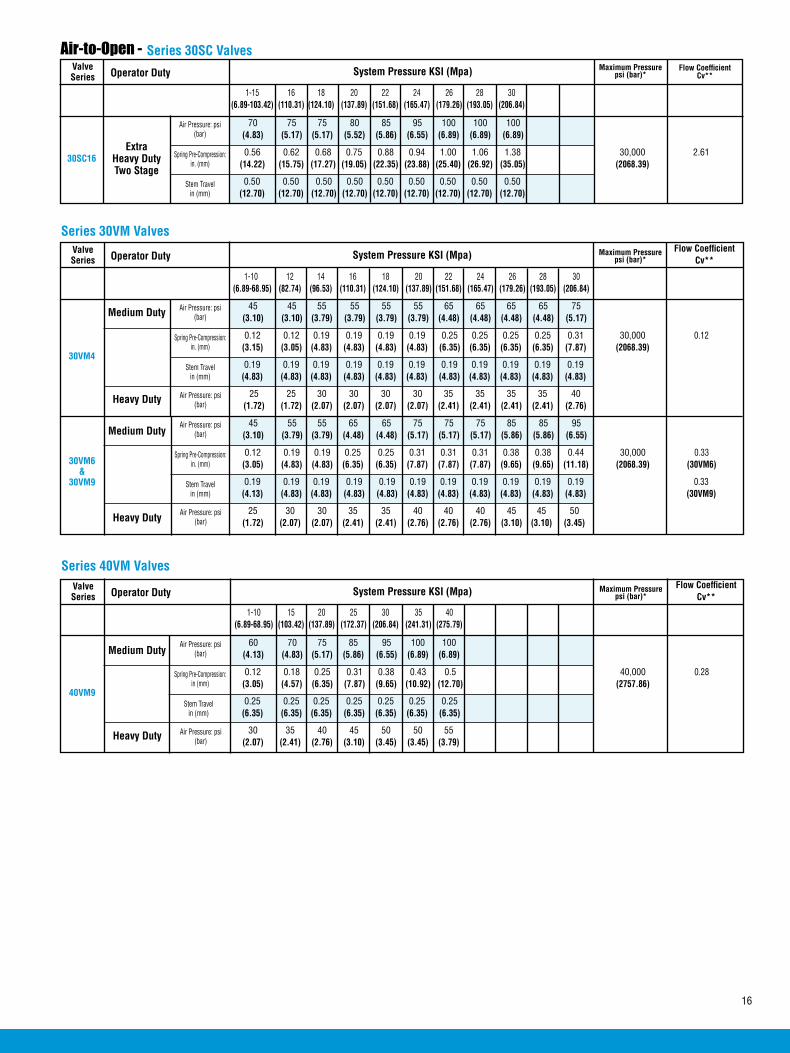
16
ValveSeries Operator Duty System Pressure KSI (Mpa) Maximum Pressure
psi (bar)*
40VM9
1-10 15 20 25 30 35 40 (6.89-68.95) (103.42) (137.89) (172.37) (206.84) (241.31) (275.79)
60 70 75 85 95 100 100 (4.13) (4.83) (5.17) (5.86) (6.55) (6.89) (6.89) Medium Duty
Series 40VM Valves
0.12 0.18 0.25 0.31 0.38 0.43 0.5 40,000 0.28 (3.05) (4.57) (6.35) (7.87) (9.65) (10.92) (12.70) (2757.86)
0.25 0.25 0.25 0.25 0.25 0.25 0.25 (6.35) (6.35) (6.35) (6.35) (6.35) (6.35) (6.35)
Air Pressure: psi (bar)
Stem Travel in (mm)
Flow Coefficient Cv**
Air Pressure: psi (bar)Heavy Duty 30 35 40 45 50 50 55
(2.07) (2.41) (2.76) (3.10) (3.45) (3.45) (3.79)
Spring Pre-Compression: in (mm)
ValveSeries Operator Duty System Pressure KSI (Mpa) Maximum Pressure
psi (bar)*
30VM4
1-10 12 14 16 18 20 22 24 26 28 30 (6.89-68.95) (82.74) (96.53) (110.31) (124.10) (137.89) (151.68) (165.47) (179.26) (193.05) (206.84)
45 45 55 55 55 55 65 65 65 65 75 (3.10) (3.10) (3.79) (3.79) (3.79) (3.79) (4.48) (4.48) (4.48) (4.48) (5.17) Medium Duty
Series 30VM Valves
0.12 0.12 0.19 0.19 0.19 0.19 0.25 0.25 0.25 0.25 0.31 30,000 0.12 (3.15) (3.05) (4.83) (4.83) (4.83) (4.83) (6.35) (6.35) (6.35) (6.35) (7.87) (2068.39)
0.19 0.19 0.19 0.19 0.19 0.19 0.19 0.19 0.19 0.19 0.19 (4.83) (4.83) (4.83) (4.83) (4.83) (4.83) (4.83) (4.83) (4.83) (4.83) (4.83)
Air Pressure: psi (bar)
Spring Pre-Compression:in. (mm)
Stem Travel in (mm)
Flow Coefficient Cv**
Air Pressure: psi (bar)Heavy Duty 25 25 30 30 30 30 35 35 35 35 40
(1.72) (1.72) (2.07) (2.07) (2.07) (2.07) (2.41) (2.41) (2.41) (2.41) (2.76)
30VM6&
30VM9
45 55 55 65 65 75 75 75 85 85 95 (3.10) (3.79) (3.79) (4.48) (4.48) (5.17) (5.17) (5.17) (5.86) (5.86) (6.55) Medium Duty
Air Pressure: psi (bar)
Spring Pre-Compression:in. (mm)
Stem Travel in (mm)
Air Pressure: psi
(bar)Heavy Duty 25 30 30 35 35 40 40 40 45 45 50 (1.72) (2.07) (2.07) (2.41) (2.41) (2.76) (2.76) (2.76) (3.10) (3.10) (3.45)
ValveSeries Operator Duty System Pressure KSI (Mpa)
30SC16
1-15 16 18 20 22 24 26 28 30 (6.89-103.42) (110.31) (124.10) (137.89) (151.68) (165.47) (179.26) (193.05) (206.84)
70 75 75 80 85 95 100 100 100 (4.83) (5.17) (5.17) (5.52) (5.86) (6.55) (6.89) (6.89) (6.89)
ExtraHeavy DutyTwo Stage
Series 30SC Valves
0.56 0.62 0.68 0.75 0.88 0.94 1.00 1.06 1.38 30,000 2.61 (14.22) (15.75) (17.27) (19.05) (22.35) (23.88) (25.40) (26.92) (35.05) (2068.39)
0.50 0.50 0.50 0.50 0.50 0.50 0.50 0.50 0.50 (12.70) (12.70) (12.70) (12.70) (12.70) (12.70) (12.70) (12.70) (12.70)
Air Pressure: psi (bar)
Spring Pre-Compression:in. (mm)
Stem Travel in (mm)
Air-to-Open - Maximum Pressure
psi (bar)*Flow Coefficient
Cv**
0.19 0.19 0.19 0.19 0.19 0.19 0.19 0.19 0.19 0.19 0.19 0.33 (4.13) (4.83) (4.83) (4.83) (4.83) (4.83) (4.83) (4.83) (4.83) (4.83) (4.83) (30VM9)
0.12 0.19 0.19 0.25 0.25 0.31 0.31 0.31 0.38 0.38 0.44 30,000 0.33 (3.05) (4.83) (4.83) (6.35) (6.35) (7.87) (7.87) (7.87) (9.65) (9.65) (11.18) (2068.39) (30VM6)
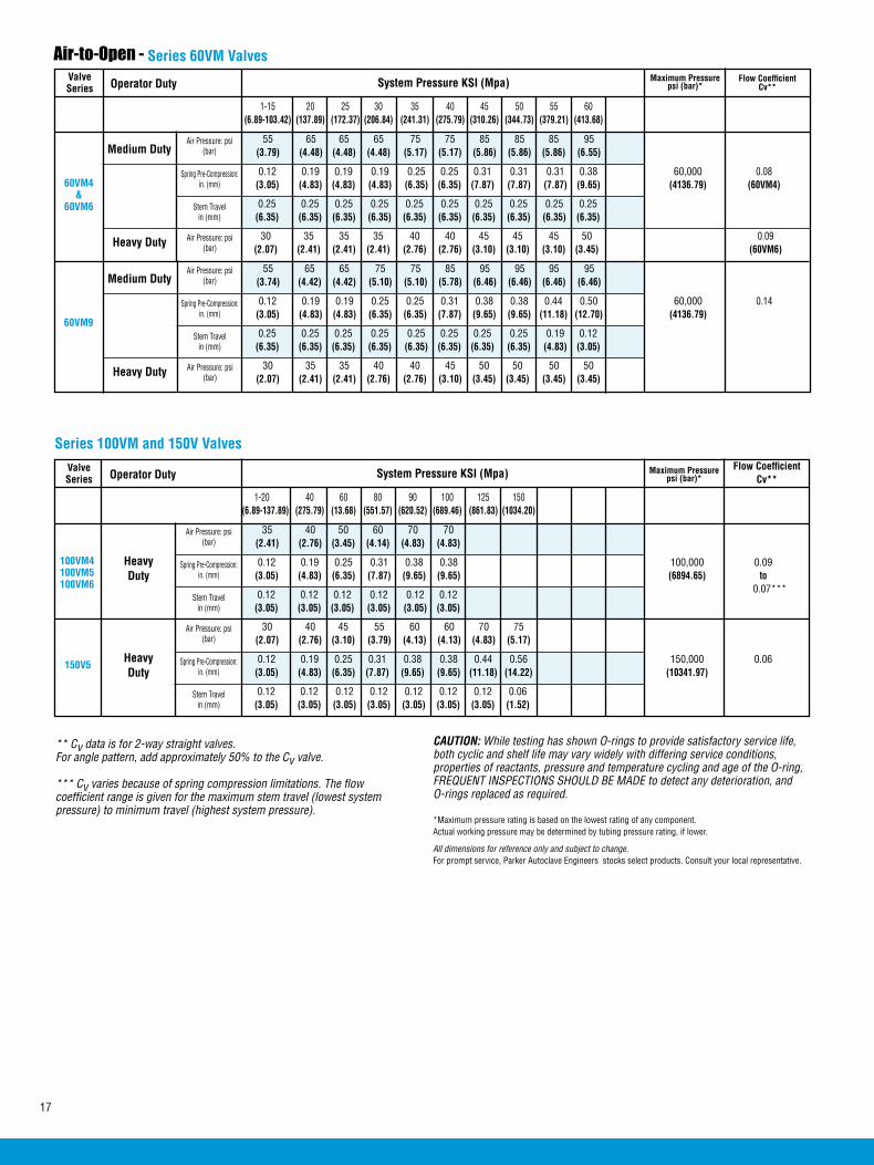
17
ValveSeries Operator Duty System Pressure KSI (Mpa) Maximum Pressure
psi (bar)*
1-20 40 60 80 90 100 125 150 (6.89-137.89) (275.79) (13.68) (551.57) (620.52) (689.46) (861.83) (1034.20)
35 40 50 60 70 70 (2.41) (2.76) (3.45) (4.14) (4.83) (4.83)
Heavy Duty
Series 100VM and 150V Valves
Air Pressure: psi (bar)
Spring Pre-Compression:in. (mm)
Stem Travel in (mm)
Flow Coefficient Cv**
150V5
30 40 45 55 60 60 70 75 (2.07) (2.76) (3.10) (3.79) (4.13) (4.13) (4.83) (5.17)
Heavy Duty
0.12 0.19 0.25 0.31 0.38 0.38 0.44 0.56 150,000 0.06 (3.05) (4.83) (6.35) (7.87) (9.65) (9.65) (11.18) (14.22) (10341.97)
0.12 0.12 0.12 0.12 0.12 0.12 0.12 0.06 (3.05) (3.05) (3.05) (3.05) (3.05) (3.05) (3.05) (1.52)
Air Pressure: psi (bar)
Spring Pre-Compression:in. (mm)
Stem Travel in (mm)
ValveSeries Operator Duty System Pressure KSI (Mpa)
60VM9
1-15 20 25 30 35 40 45 50 55 60 (6.89-103.42) (137.89) (172.37) (206.84) (241.31) (275.79) (310.26) (344.73) (379.21) (413.68)
55 65 65 65 75 75 85 85 85 95 (3.79) (4.48) (4.48) (4.48) (5.17) (5.17) (5.86) (5.86) (5.86) (6.55) Medium Duty
Series 60VM Valves
0.12 0.19 0.19 0.19 0.25 0.25 0.31 0.31 0.31 0.38 60,000 0.08 (3.05) (4.83) (4.83) (4.83) (6.35) (6.35) (7.87) (7.87) (7.87) (9.65) (4136.79) (60VM4)
0.25 0.25 0.25 0.25 0.25 0.25 0.25 0.25 0.25 0.25 (6.35) (6.35) (6.35) (6.35) (6.35) (6.35) (6.35) (6.35) (6.35) (6.35)
Air Pressure: psi (bar)
Spring Pre-Compression:in. (mm)
Stem Travel in (mm)
Air Pressure: psi (bar)Heavy Duty 30 35 35 35 40 40 45 45 45 50 0.09
(2.07) (2.41) (2.41) (2.41) (2.76) (2.76) (3.10) (3.10) (3.10) (3.45) (60VM6)
60VM4&
60VM6
55 65 65 75 75 85 95 95 95 95 (3.74) (4.42) (4.42) (5.10) (5.10) (5.78) (6.46) (6.46) (6.46) (6.46) Medium Duty
0.25 0.25 0.25 0.25 0.25 0.25 0.25 0.25 0.19 0.12 (6.35) (6.35) (6.35) (6.35) (6.35) (6.35) (6.35) (6.35) (4.83) (3.05)
Air Pressure: psi (bar)
Spring Pre-Compression:in. (mm)
Stem Travel in (mm)
Air Pressure: psi (bar)Heavy Duty
0.12 0.19 0.25 0.31 0.38 0.38 100,000 0.09 (3.05) (4.83) (6.35) (7.87) (9.65) (9.65) (6894.65) to 0.07***
Air-to-Open -
0.12 0.12 0.12 0.12 0.12 0.12 (3.05) (3.05) (3.05) (3.05) (3.05) (3.05)
100VM4100VM5100VM6
Maximum Pressure psi (bar)*
Flow Coefficient Cv**
** Cv data is for 2-way straight valves.For angle pattern, add approximately 50% to the Cv valve.
*** Cv varies because of spring compression limitations. The flow coefficient range is given for the maximum stem travel (lowest system pressure) to minimum travel (highest system pressure).
CAUTION: While testing has shown O-rings to provide satisfactory service life, both cyclic and shelf life may vary widely with differing service conditions, properties of reactants, pressure and temperature cycling and age of the O-ring, FREQUENT INSPECTIONS SHOULD BE MADE to detect any deterioration, and O-rings replaced as required.
*Maximum pressure rating is based on the lowest rating of any component. Actual working pressure may be determined by tubing pressure rating, if lower.
All dimensions for reference only and subject to change.For prompt service, Parker Autoclave Engineers stocks select products. Consult your local representative.
0.12 0.19 0.19 0.25 0.25 0.31 0.38 0.38 0.44 0.50 60,000 0.14 (3.05) (4.83) (4.83) (6.35) (6.35) (7.87) (9.65) (9.65) (11.18) (12.70) (4136.79)
30 35 35 40 40 45 50 50 50 50 (2.07) (2.41) (2.41) (2.76) (2.76) (3.10) (3.45) (3.45) (3.45) (3.45)


02-0121SE January2013© 2013 Parker Hannifin Corporation | Autoclave Engineers is a registered trademark of the Parker Hannifin Corporation
Parker Hannifin Manufacturing Ltd. Instrumentation Products Division, Europe Industrial Estate WhitemillWexford, Republic of IrelandPH: 353 53 914 1566FAX: 353 53 914 1582
Instrumentation Products DivisionAutoclave Engineers Operation8325 Hessinger DriveErie, Pennsylvania 16509-4679 USAPH: 814-860-5700 FAX: 814-860-5811www.autoclave.com
WARNING
FAILURE, IMPROPER SELECTION OR IMPROPER USE OF THE PRODUCTS AND/OR SYSTEMS DESCRIBED HEREIN OR RELATED ITEMS CAN CAUSE DEATH, PERSONAL INJURY AND PROPERTY DAMAGE.This document and other information from Parker Hannifin Corporation, its subsidiaries and authorized distributors provide product and/or system options for further investigation by users having technical expertise. It is important that you analyze all aspects of your application and review the information concerning the product or system in the current product catalog. Due to the variety of operating conditions and applications for these products or systems, the user, through its own analysis and testing, is solely responsible for making the final selection of the products and systems and assuring that all performance, safety and warning requirements of the application are met. The products described herein, including without limitation, product features, specifications, designs, availability and pricing, are subject to change by Parker Hannifin Corporation and its subsidiaries at any time without notice.
Offer of Sale
The items described in this document are available for sale by Parker Hannifin Corporation, its subsidiaries or its authorized distributors. Any sale contract entered by Parker will be governed by the provisions stated in Parker's standard terms and conditions of sale (copy available upon request).
ISO-9001 Certified
Caution! Do not mix or interchange parts or tubing with those of other manufacturers. Doing so is unsafe and will void warranty.
Caution! Parker Autoclave Engineers Valves, Fittings and Tools are not designed to work with common commercial instrument tubing and will only work with tubing built to Parker Autoclave Engineers AES Specifications. Failure to do so will void warranty.
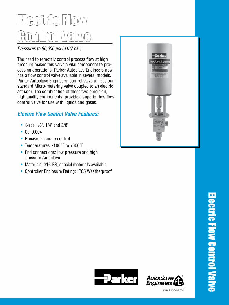
Electric FlowControl Valve
Electric Flow Control Valve
Pressures to 60,000 psi (4137 bar) The need to remotely control process flow at high pressure makes this valve a vital component to pro-cessing operations. Parker Autoclave Engineers now has a flow control valve available in several models. Parker Autoclave Engineers' control valve utilizes our standard Micro-metering valve coupled to an electric actuator. The combination of these two precision, high quality components, provide a superior low flow control valve for use with liquids and gases.
Electric Flow Control Valve Features:
• Sizes 1/8", 1/4" and 3/8"• Cv: 0.004• Precise, accurate control• Temperatures: -100°F to +600°F• End connections: low pressure and high
pressure Autoclave• Materials: 316 SS, special materials available• Controller Enclosure Rating: IP65 Weatherproof
www.autoclave.com
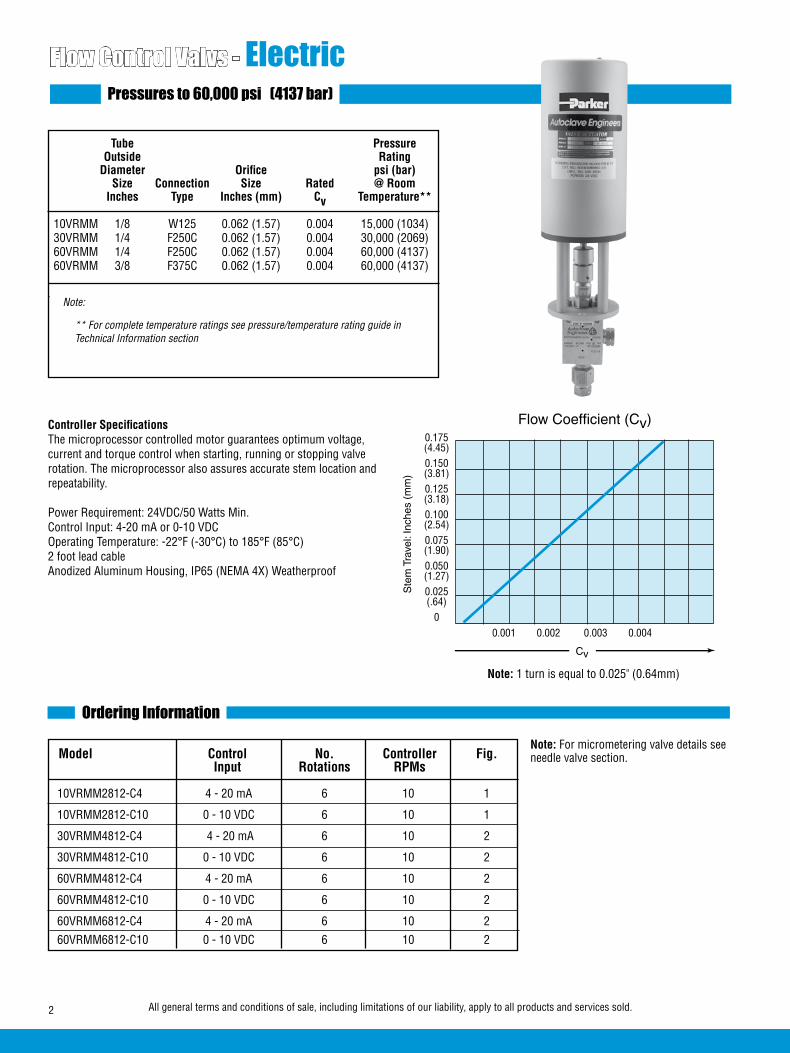
Flow Control Valvs - ElectricPressures to 60,000 psi (4137 bar)
Tube Pressure Outside Rating Diameter Orifice psi (bar) Size Connection Size Rated @ Room Inches Type Inches (mm) Cv Temperature** 10VRMM 1/8 W125 0.062 (1.57) 0.004 15,000 (1034) 30VRMM 1/4 F250C 0.062 (1.57) 0.004 30,000 (2069) 60VRMM 1/4 F250C 0.062 (1.57) 0.004 60,000 (4137) 60VRMM 3/8 F375C 0.062 (1.57) 0.004 60,000 (4137) .
Ordering Information
Flow Coefficient (Cv)
Cv
Ste
m T
rave
l: In
ches
(m
m)
0.001 0.002 0.003 0.004
0.175
0.150
0.125
0.100
0.075
0.050
0.025
0
(4.45)
(3.81)
(3.18)
(2.54)
(1.90)
(1.27)
(.64)
2 All general terms and conditions of sale, including limitations of our liability, apply to all products and services sold.
Note:
** For complete temperature ratings see pressure/temperature rating guide in Technical Information section
Note: 1 turn is equal to 0.025" (0.64mm)
Controller Specifications The microprocessor controlled motor guarantees optimum voltage, current and torque control when starting, running or stopping valve rotation. The microprocessor also assures accurate stem location and repeatability.
Power Requirement: 24VDC/50 Watts Min.Control Input: 4-20 mA or 0-10 VDCOperating Temperature: -22°F (-30°C) to 185°F (85°C)2 foot lead cableAnodized Aluminum Housing, IP65 (NEMA 4X) Weatherproof
Model Control No. Controller Fig. Input Rotations RPMs
10VRMM2812-C4 4 - 20 mA 6 10 1
10VRMM2812-C10 0 - 10 VDC 6 10 1
30VRMM4812-C4 4 - 20 mA 6 10 2
30VRMM4812-C10 0 - 10 VDC 6 10 2
60VRMM4812-C4 4 - 20 mA 6 10 2
60VRMM4812-C10 0 - 10 VDC 6 10 2
60VRMM6812-C4 4 - 20 mA 6 10 2
60VRMM6812-C10 0 - 10 VDC 6 10 2
Note: For micrometering valve details see needle valve section.

Block Catalog Diameter Orifice Thick- Valve Number Tube Diameter A B C D E F G J K ness Pattern
Valve Options Valve MaintenanceExtreme Temperatures Standard Parker Autoclave Engineers valves with PTFE packing may be operated to 450°F (232°C). Optional packing or trim material available by adding the following suffixes to catalog order number.=
TG - standard valve with PTFE glass packing to 600°F (316°C).B - standard valve with cryogenic trim material and PTFE packing to -100°F (-73°C).
=Parker Autoclave Engineers does not recommend compression sleeve connec-tions below 0°F (-17.8°C) or above 650°F (343°C). For additional valve options, contact your Sales Representative.
See Needle Valve options for stem and seat coatings for erosive service.Metering valve not to be used as a shutoff valve.
Repair Kits: add “R” to the front of valve catalog number for proper repair kit. (Example: R60VRMM4882-C)
Valve Bodies: Valve bodies are available. Order using the eight (8) digit part number found on the valve drawing or contact your Sales Representative for information. Consult your Parker Autoclave Engineers representative for pricing on repair kits and valve bodies. Refer to the Tools, Installation, Operation and Mainte-nance section for proper maintenance procedures.
Dimensions - inches (mm)
10VRMM2812-C4
10VRMM2812-C10 1/8 0.062 1.50 0.88 0.31 0.94 1.56 4.50 2.50 4.75 3.50 0.75 (3.17) (1.57) (38.10) (22.35) (7.87) (23.87) (39.62) (114.30) (63.50) (120.65) (88.90) (19.05)
Outside
30VRMM4812-C4
30VRMM4812-C10
1/4 0.062 2.00 1.00 *0.50 1.12 2.00 3.50 3.50 4.75 3.50 1.00 (6.35) (1.57) (50.80) (25.40) (12.70) (28.44) (50.80) (88.90) (88.90) (120.65) (88.90) (25.40) 1/4 0.062 2.00 1.00 0.50 1.31 2.63 3.50 3.50 8.30 4.10 1.00 (6.35) (1.57) (50.80) (25.40) (12.70) (33.27) (66.80) (88.90) (88.90) (210.80) (104.14) (25.40) 3/8 0.062 2.00 1.00 0.53 1.31 2.63 3.50 3.50 8.30 4.10 1.00 (9.53) (1.57) (50.80) (25.40) (13.46) (33.27) (66.80) (88.90) (88.90) (210.80) (104.14) (25.40)
60VRMM4812-C4
60VRMM4812-C10
60VRMM6812-C4
60VRMM6812-C10
Figure 1
See Figure 1
Figure 2
See Figure 2
All general terms and conditions of sale, including limitations of our liability, apply to all products and services sold. 3
*Distance gland extends
K
J
J
F
D
C
BA
E
K
F
DC
BA
J
E
+
+ +
+
2.50(63.50)
0.75(19.05)
3.50(88.90)
Electronic ValveActuator
View A
Coupling
Mounting Bracket
Electronic ValveActuator
Mounting Rods
Coupling
Support Plate
0.250(6.35)
1.50(38.1)
0.50(12.70) 0.50
(12.70)
0.20 TYP(5.16)
0.34 TYP(8.74)
2.90(73.66)
K
J
J
F
D
C
BA
E
K
F
DC
BA
J
E
+
+ +
+
2.50(63.50)
0.75(19.05)
3.50(88.90)
Electronic ValveActuator
View A
Coupling
Mounting Bracket
Electronic ValveActuator
Mounting Rods
Coupling
Support Plate
0.250(6.35)
1.50(38.1)
0.50(12.70) 0.50
(12.70)
0.20 TYP(5.16)
0.34 TYP(8.74)
2.90(73.66)
K
J
J
F
D
C
BA
E
K
F
DC
BA
J
E
+
+ +
+
2.50(63.50)
0.75(19.05)
3.50(88.90)
Electronic ValveActuator
View A
Coupling
Mounting Bracket
Electronic ValveActuator
Mounting Rods
Coupling
Support Plate
0.250(6.35)
1.50(38.1)
0.50(12.70) 0.50
(12.70)
0.20 TYP(5.16)
0.34 TYP(8.74)
2.90(73.66)
K
J
J
F
D
C
BA
E
K
F
DC
BA
J
E
+
+ +
+
2.50(63.50)
0.75(19.05)
3.50(88.90)
Electronic ValveActuator
View A
Coupling
Mounting Bracket
Electronic ValveActuator
Mounting Rods
Coupling
Support Plate
0.250(6.35)
1.50(38.1)
0.50(12.70) 0.50
(12.70)
0.20 TYP(5.16)
0.34 TYP(8.74)
2.90(73.66)
10VRMM
30VRMM/60VRMM
60VRMM
30VRMM
Mounting DimensionsView A
Mounting Dimensions

02-9228BE January2013© 2013 Parker Hannifin Corporation | Autoclave Engineers is a registered trademark of the Parker Hannifin Corporation
Parker Hannifin Manufacturing Ltd. Instrumentation Products Division, Europe Industrial Estate WhitemillWexford, Republic of IrelandPH: 353 53 914 1566FAX: 353 53 914 1582
Instrumentation Products DivisionAutoclave Engineers Operation8325 Hessinger DriveErie, Pennsylvania 16509-4679 USAPH: 814-860-5700 FAX: 814-860-5811www.autoclave.com
WARNING
FAILURE, IMPROPER SELECTION OR IMPROPER USE OF THE PRODUCTS AND/OR SYSTEMS DESCRIBED HEREIN OR RELATED ITEMS CAN CAUSE DEATH, PERSONAL INJURY AND PROPERTY DAMAGE.This document and other information from Parker Hannifin Corporation, its subsidiaries and authorized distributors provide product and/or system options for further investigation by users having technical expertise. It is important that you analyze all aspects of your application and review the information concerning the product or system in the current product catalog. Due to the variety of operating conditions and applications for these products or systems, the user, through its own analysis and testing, is solely responsible for making the final selection of the products and systems and assuring that all performance, safety and warning requirements of the application are met. The products described herein, including without limitation, product features, specifications, designs, availability and pricing, are subject to change by Parker Hannifin Corporation and its subsidiaries at any time without notice.
Offer of Sale
The items described in this document are available for sale by Parker Hannifin Corporation, its subsidiaries or its authorized distributors. Any sale contract entered by Parker will be governed by the provisions stated in Parker's standard terms and conditions of sale (copy available upon request).
ISO-9001 Certified
Caution! Do not mix or interchange parts or tubing with those of other manufacturers. Doing so is unsafe and will void warranty.
Caution! Parker Autoclave Engineers Valves, Fittings and Tools are not designed to work with common commercial instrument tubing and will only work with tubing built to Parker Autoclave Engineers AES Specifications. Failure to do so will void warranty.

Since 1945 Parker Autoclave Engineers has designed and built premium quality valves, fittings and tubing. This commitment to engineering and manufacturing excellence has earned Parker Autoclave Engineers a reputation for reliable, efficient product performance. Parker Autoclave Engineers has long been established as the world leader in high pressure fluid handling compo-nents for the chemical/petrochemical, research, and oil and gas industries.
Low Pressure Fittings and Tubing Features:
• Single-ferrule compression sleeve.
• Fast easy make-up of connection.
• Available sizes are 1/16”, 1/8”, 1/4”, 3/8”, & 1/2”.
• Fittings manufactured from cold worked 316 stainless steel.
• Tubing is manufactured from dual rated 316/316L and 304/304L annealed stainless steel.
• All items available in special materials.
• Operating temperatures from -100°F (-73°C) to 650°F (343°C).
• Molybdenum disulfide-coated gland nuts to prevent galling.
The Low Pressure Series uses Parker Autoclave Engineers' SpeedBite connection. This single-ferrule compression sleeve connection delivers fast, easy make-up and reliable bubble-tight performance, in liquid or gas service.
Fittings and Tubing - Low PressureFittings and Tubing
Pressures to 15,000 psi (1034 bar)
Low Pressure
www.autoclave.com

Elbow SL2200 W125 1/8 15,000 0.094 1.00 1.50 0.31 0.38 0.75 0.75 0.62 (3.18) (1034.19) (2.39) (25.40) (38.10) (7.87) (9.53) (19.05) (19.05) (15.75) SL4400 SW250 1/4 15,000 0.188 1.38 2.00 0.44 0.63 1.00 1.00 0.75 (6.35) (1034.19) (4.78) (35.05) (50.80) (11.18) (15.88) (25.40) (25.40) (19.05) SL6600 SW375 3/8 15,000 0.250 1.38 2.00 0.53 0.75 1.00 1.00 0.75 (9.53) (1034.19) (6.35) (35.05) (50.80) (13.46) (19.05) (25.40) (25.40) (19.05) SL8800 SW500 1/2 10,000 0.375 1.75 2.50 0.53 0.93 1.25 1.25 1.00 (12.70) (689.46) (9.53) (44.45) (63.50) (13.46) (23.62) (31.75) (31.75) (25.40)
Dimensions - inches (mm)
Fittings and Tubing - Low Pressure FittingsPressures to 15,000 psi (1034 bar)
See Figure 1
Parker Autoclave Engineers Low Pressure Fittings are designed for use with low pressure valves and tubing. These fittings feature improved SpeedBite compression connections with larger orifices for excellent flow capabilities. Parker Autoclave Engi-neers fittings and components are manufactured of cold-worked type 316 stainless steel. Optional materials are available upon request.
Connection ComponentsAll valves and fittings are supplied complete with appropriate glands and compression sleeves. To order these components sepa-rately, use order numbers listed. When using plug, sleeve is not required.
† When ordering glands separately for 10V Series 1/4” and 3/8” valves, substitute 10N for SMN.
1/16” tubing system components are available in the mini-fitting series. 1/16” tubing components can be used in 10V Series valves and fittings if required. Consult factory for information on 1/16” tubing assembly in 1/8” tubing components.
To ensure proper fit use Parker Autoclave Engineers tubing. For mounting hole op-tion add suffix PM to catalog number. Consult factory for mounting hole dimensions.
Add tube size ( ) 1/8” - 20 1/4” - 40 3/8” - 60 1/2” - 80
Example: 1/4” Gland - SMN 40
Catalog Number
Connection Type
Outside Diameter
Tube
Pressure Rating
psi (bar)*
Minimum Opening
Block Thickness
Fitting Pattern A B C D E F G
Typical Thickness
Elbow
Figure 1
D HEXF
C
A
B
E
Plug SP ( )
Sleeve SSL ( )
Gland SMN ( )
*Maximum pressure rating is based on the lowest rating of any component. Actual working pressure may be determined by tubing pressure rating, if lower.
All dimensions for reference only and subject to change.For prompt service, Parker Autoclave Engineers stocks select prod-ucts. Consult your local representative.
2 All general terms and conditions of sale, including limitations of our liability, apply to all products and services sold.
Note: Special material glands may be supplied with four flats in place of standard hex.

Dimensions - inches (mm)Catalog Number
Connection Type
Outside Diameter
Tube
Pressure Rating
psi (bar)*
Minimum Opening
Block Thickness
Fitting Pattern A B C D E F G
Typical Thickness
Tee ST2220 W125 1/8 15,000 0.094 1.00 1.50 0.31 0.38 0.75 0.75 0.62 (3.18) (1034.19) (2.39) (25.40) (38.10) (7.87) (9.53) (19.05) (19.05) (15.75) ST4440 SW250 1/4 15,000 0.188 1.38 2.00 0.44 0.63 1.00 1.00 0.75 (6.35) (1034.19) (4.78) (35.05) (50.80) (11.18) (15.88) (25.40) (25.40) (19.05) ST6660 SW375 3/8 15,000 0.250 1.38 2.00 0.53 0.75 1.00 1.00 0.75 (9.53) (1034.19) (6.35) (35.05) (50.80) (13.46) (19.05) (25.40) (25.40) (19.05) ST8880 SW500 1/2 10,000 0.375 1.75 2.50 0.53 0.93 1.25 1.25 1.00 (12.70) (689.46) (9.53) (44.45) (63.50) (13.46) (23.62) (31.75) (31.75) (25.40)
See Figure 2
Cross SX2222 W125 1/8 15,000 0.094 1.50 1.50 0.31 0.38 0.75 0.75 0.62 (3.18) (1034.19) (2.39) (38.10) (38.10) (7.87) (9.53) (19.05) (19.05) (15.75) SX4444 SW250 1/4 15,000 0.188 2.00 2.00 0.44 0.63 1.00 1.00 0.75 (6.35) (1034.19) (4.78) (50.80) (50.80) (11.18) (15.88) (25.40) (25.40) (19.05) SX6666 SW375 3/8 15,000 0.250 2.00 2.00 0.53 0.75 1.00 1.00 0.75 (9.53) (1034.19) (6.35) (50.80) (50.80) (13.46) (19.05) (25.40) (25.40) (19.05) SX8888 SW500 1/2 10,000 0.375 2.50 2.50 0.53 0.93 1.25 1.25 1.00 (12.70) (689.46) (9.53) (63.50) (63.50) (13.46) (23.62) (31.75) (31.75) (25.40)
See Figure 3
Bulkhead Coupling 15BF2211 W125 1/8 15,000 0.094 0.690 1.75 0.31 0.38 0.38 0.75 0.38 (3.18) (1034.19) (2.39) (17.53) (44.45) (7.87) (9.53) (9.53) (19.05) (9.53) 6BF4422 SW250 1/4 15,000 0.188 0.940 1.88 0.44 0.63 0.50 1.00 0.38 (6.35) (1034.19) (4.78) (23.88) (47.75) (11.18) (15.88) (12.70) (25.40) (9.53) 6BF6622 SW375 3/8 15,000 0.250 0.940 1.88 0.53 0.75 0.50 1.00 0.38 (9.53) (1034.19) (6.35) (23.88) (47.75) (13.46) (19.05) (12.70) (25.40) (9.53) 4BF8822 SW500 1/2 10,000 0.375 1.120 2.38 0.53 0.93 0.78 1.38 0.38 (12.70) (689.46) (9.53) (28.45) (60.45) (13.46) (23.62) (19.81) (35.05) (9.53)
See Figure 5
Straight Coupling 15F2211 W125 1/8 15,000 0.094 0.50 1.25 0.31 0.38 (3.18) (1034.19) (2.39) (12.70) (31.75) (7.87) (9.53) 6F4422 SW250 1/4 15,000 0.188 0.62 1.62 0.44 0.63 (6.35) (1034.19) (4.78) (15.75) (41.15) (11.18) (15.88) 6F6622 SW375 3/8 15,000 0.250 0.75 1.75 0.53 0.75 (9.53) (1034.19) (6.35) (19.05) (44.45) (13.46) (19.05) 4F8822 SW500 1/2 10,000 0.375 1.00 2.00 0.53 0.93 (12.70) (689.46) (9.53) (25.40) (50.80) (13.46) (23.62)
See Figure 4
Tee
Figure 2
Cross
Figure 3
DHEX
F
C
A
B
E
Straight Coupling
Figure 4
DHEX
CB
A HEX
Bulkhead Coupling
Figure 5
G MAX
CBE
ADHEX
FHEX
D HEXF
C
A
B
E
*Maximum pressure rating is based on the lowest rating of any component. Actual working pressure may be determined by tubing pressure rating, if lower.
All dimensions for reference only and subject to change.For prompt service, Parker Autoclave Engineers stocks select products. Consult your local representative.
All general terms and conditions of sale, including limitations of our liability, apply to all products and services sold. 3
(A=Panel hole drill size)
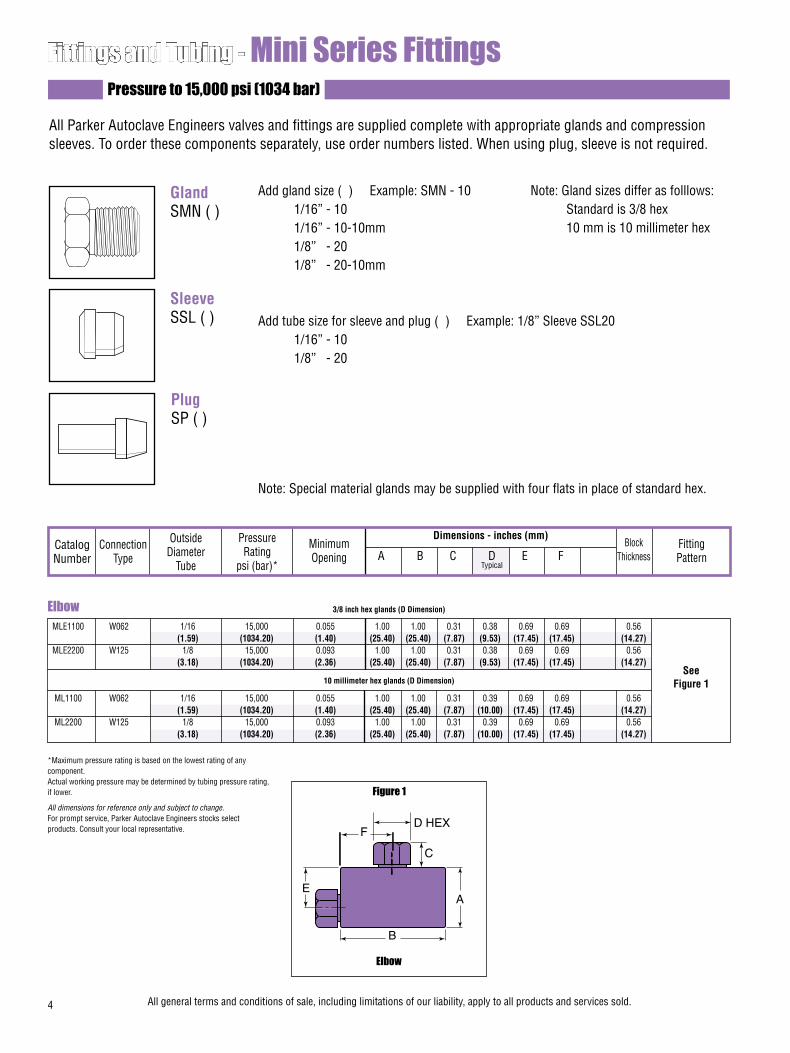
MLE1100 W062 1/16 15,000 0.055 1.00 1.00 0.31 0.38 0.69 0.69 0.56 (1.59) (1034.20) (1.40) (25.40) (25.40) (7.87) (9.53) (17.45) (17.45) (14.27) MLE2200 W125 1/8 15,000 0.093 1.00 1.00 0.31 0.38 0.69 0.69 0.56 (3.18) (1034.20) (2.36) (25.40) (25.40) (7.87) (9.53) (17.45) (17.45) (14.27)
ML1100 W062 1/16 15,000 0.055 1.00 1.00 0.31 0.39 0.69 0.69 0.56 (1.59) (1034.20) (1.40) (25.40) (25.40) (7.87) (10.00) (17.45) (17.45) (14.27) ML2200 W125 1/8 15,000 0.093 1.00 1.00 0.31 0.39 0.69 0.69 0.56 (3.18) (1034.20) (2.36) (25.40) (25.40) (7.87) (10.00) (17.45) (17.45) (14.27)
Dimensions - inches (mm)
Fittings and Tubing - Mini Series FittingsPressure to 15,000 psi (1034 bar)
See Figure 1
All Parker Autoclave Engineers valves and fittings are supplied complete with appropriate glands and compression sleeves. To order these components separately, use order numbers listed. When using plug, sleeve is not required.
Gland SMN ( )
Sleeve SSL ( )
Plug SP ( )
Add gland size ( ) Example: SMN - 10 1/16” - 10 1/16” - 10-10mm 1/8” - 20 1/8” - 20-10mm
Add tube size for sleeve and plug ( ) Example: 1/8” Sleeve SSL20 1/16” - 10 1/8” - 20
Note: Special material glands may be supplied with four flats in place of standard hex.
Catalog Number
Connection Type
Outside Diameter
Tube
Pressure Rating
psi (bar)*
Minimum Opening
Block Thickness
Fitting Pattern A B C D E F
Typical
Elbow
Figure 1
D HEXF
C
A
B
E
*Maximum pressure rating is based on the lowest rating of any component. Actual working pressure may be determined by tubing pressure rating, if lower.
All dimensions for reference only and subject to change.For prompt service, Parker Autoclave Engineers stocks select products. Consult your local representative.
4 All general terms and conditions of sale, including limitations of our liability, apply to all products and services sold.
Elbow 3/8 inch hex glands (D Dimension)
10 millimeter hex glands (D Dimension)
Note: Gland sizes differ as folllows: Standard is 3/8 hex 10 mm is 10 millimeter hex
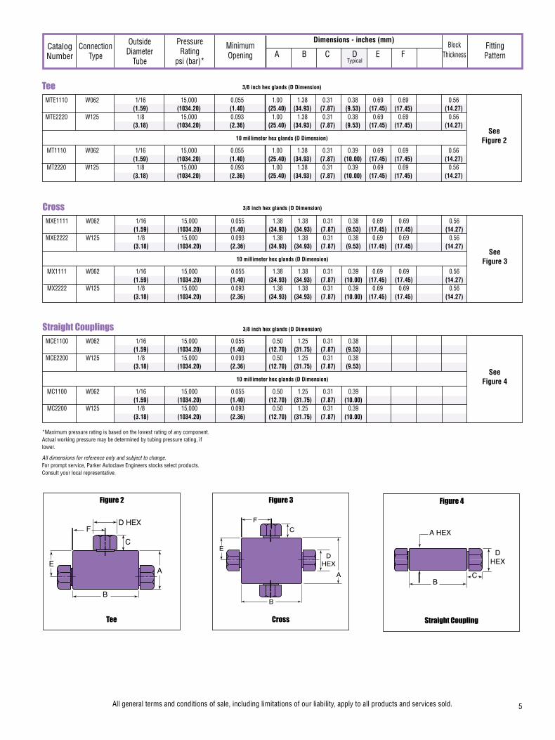
MXE1111 W062 1/16 15,000 0.055 1.38 1.38 0.31 0.38 0.69 0.69 0.56 (1.59) (1034.20) (1.40) (34.93) (34.93) (7.87) (9.53) (17.45) (17.45) (14.27) MXE2222 W125 1/8 15,000 0.093 1.38 1.38 0.31 0.38 0.69 0.69 0.56 (3.18) (1034.20) (2.36) (34.93) (34.93) (7.87) (9.53) (17.45) (17.45) (14.27)
MX1111 W062 1/16 15,000 0.055 1.38 1.38 0.31 0.39 0.69 0.69 0.56 (1.59) (1034.20) (1.40) (34.93) (34.93) (7.87) (10.00) (17.45) (17.45) (14.27) MX2222 W125 1/8 15,000 0.093 1.38 1.38 0.31 0.39 0.69 0.69 0.56 (3.18) (1034.20) (2.36) (34.93) (34.93) (7.87) (10.00) (17.45) (17.45) (14.27)
Dimensions - inches (mm)Catalog Number
Connection Type
Outside Diameter
Tube
Pressure Rating
psi (bar)*
Minimum Opening
Block Thickness
Fitting Pattern A B C D E F
Typical
MCE1100 W062 1/16 15,000 0.055 0.50 1.25 0.31 0.38 (1.59) (1034.20) (1.40) (12.70) (31.75) (7.87) (9.53) MCE2200 W125 1/8 15,000 0.093 0.50 1.25 0.31 0.38 (3.18) (1034.20) (2.36) (12.70) (31.75) (7.87) (9.53)
MC1100 W062 1/16 15,000 0.055 0.50 1.25 0.31 0.39 (1.59) (1034.20) (1.40) (12.70) (31.75) (7.87) (10.00) MC2200 W125 1/8 15,000 0.093 0.50 1.25 0.31 0.39 (3.18) (1034.20) (2.36) (12.70) (31.75) (7.87) (10.00)
10 millimeter hex glands (D Dimension)
See Figure 3
See Figure 4
MTE1110 W062 1/16 15,000 0.055 1.00 1.38 0.31 0.38 0.69 0.69 0.56 (1.59) (1034.20) (1.40) (25.40) (34.93) (7.87) (9.53) (17.45) (17.45) (14.27) MTE2220 W125 1/8 15,000 0.093 1.00 1.38 0.31 0.38 0.69 0.69 0.56 (3.18) (1034.20) (2.36) (25.40) (34.93) (7.87) (9.53) (17.45) (17.45) (14.27)
MT1110 W062 1/16 15,000 0.055 1.00 1.38 0.31 0.39 0.69 0.69 0.56 (1.59) (1034.20) (1.40) (25.40) (34.93) (7.87) (10.00) (17.45) (17.45) (14.27) MT2220 W125 1/8 15,000 0.093 1.00 1.38 0.31 0.39 0.69 0.69 0.56 (3.18) (1034.20) (2.36) (25.40) (34.93) (7.87) (10.00) (17.45) (17.45) (14.27)
10 millimeter hex glands (D Dimension)See
Figure 2
Tee
Figure 2
D HEXF
C
A
B
E
Cross
Figure 3
DHEX
F
C
A
B
E
Straight Coupling
Figure 4
*Maximum pressure rating is based on the lowest rating of any component. Actual working pressure may be determined by tubing pressure rating, if lower.
All dimensions for reference only and subject to change.For prompt service, Parker Autoclave Engineers stocks select products. Consult your local representative.
All general terms and conditions of sale, including limitations of our liability, apply to all products and services sold. 5
Straight Couplings
Cross
Tee 3/8 inch hex glands (D Dimension)
3/8 inch hex glands (D Dimension)
3/8 inch hex glands (D Dimension)
10 millimeter hex glands (D Dimension)
DHEX
CB
A HEX

Fittings and Tubing - Low Pressure TubingPressures to 15,000 psi (1034 bar)
Parker Autoclave Engineers offers a complete selection of annealed, seamless stain-less steel tubing designed to match the performance standards of Parker Autoclave low pressure valves and fittings. Parker Autoclave Engineers low pressure tubing is furnished in random lengths between 20 feet (6 meters) and 26.5 feet (8.0 meters). The average is 24 feet (7.3 meters). The tubing is available in five sizes and a variety of materials. In order to ensure proper sleeve “bite” into tubing, Parker Autoclave Engineers specifies and controls the strength levels of both the tube and sleeve materials.
Catalog Tube Fits Tube Size Inches (mm) Flow Working Pressure psi (bar)* Number Materials Connection Outside Inside Wall Area 0 - 100°F 200°F 400°F 600°F 650°F Type Diameter Diameter Thickness in.2 (mm2) -17.8 to 37.8°C 93°C 204°C 316°C 343°C
Special MaterialsIn addition to the type 316/316L and 304/304L stainless steel tubing listed in this section, Parker Autoclave Engineers has a limited stock of hard-to-obtain shorter lengths of the following tubing materials:Monel 400*, Inconel 600*, Titanium Grade 2*, Nickel 200*, Hastelloy C276* - (* Trademark names)
Please consult factory for stock availabilty.
Tubing ToleranceNominal Tubing Size Tolerance/Outside Diameter inches (mm) inches (mm)1/16 (1.59) .064/.062 (1.62/1.57)1/8 (3.18) .128/.125 (3.25/3.18)1/4 (6.35) .254/.250 (6.45/6.35)3/8 (9.53) .379/.375 (9.74/9.53)1/2 (12.70) .505/.500 (12.83/12.70)
6All general terms and conditions of sale, including limitations of our liability, apply to all products and services sold.
Inspection and TestingParker Autoclave Engineers low pressure tubing is inspected for compliance with specified defect restrictions as well as carburization or intergranular carbide precipitation. The tubing outside diameter and wall thickness is controlled within close tolerance to assure proper fit. Sample pieces of tube (for each lot) are tested to confirm mechanical properties for proper compression sleeve “bite” and pressure capability. Furthermore, the sample tubes are pressure tested as a final check.
MS15-070 316SS W062 1/16 0.026 0.018 0.0005 15,000 15,000 14,400 13,600 12,600 (1.59) (0.66) (0.46) (0.32) (1034.20) (1034.20) (992.83) (937.67) (868.73)
MS15-200 316SS 0.052 0.036 0.002 15,000 15,000 14,400 13,600 12,600 (1.32) (0.91) (1.29) (1034.20) (1034.20) (992.83) (937.67) (868.73)
MS15-166= 304SS 0.069 0.028 0.004 9,950 9,400 8,550 8,450 8,000 (1.75) (0.71) (2.58) (686.02) (648.10) (589.49) (582.60) (551.57)
MS15-203 316SS 0.084 0.083 0.029 15,000 15,000 14,400 13,600 12,600 (2.13) (2.11) (18.71) (1034.16) (1034.16) (992.83) (937.67) (868.73)
MS15-055 316SS 0.125 0.062 0.012 11,650 11,650 11,250 10,600 9,850 (3.18) (1.57) (7.74) (803.23) (761.86) (775.65) (730.83) (679.12)
MS15-161= 304SS 1/4 0.180 0.035 0.026 5,450 5,150 4,700 4,600 4,400 (6.35) (4.57) (0.89) (16.77) (375.76) (355.07) (324.05) (317.15) (303.36)
MS15-069 316SS 0.180 0.035 0.026 5,450 5,450 5,250 4,950 4,600 (4.57) (0.89) (16.77) (375.76) (375.76) (361.97) (341.29) (317.15)
MS15-158= 304SS 0.194 0.028 0.029 4,600 4,350 3,950 3,900 3,700 (4.93) (0.71) (18.71) (317.15) (299.92) (272.34) (272.34) (255.10)
MS15-204 316SS 0.139 0.118 0.015 15,000 15,000 14,400 13,600 12,600 (3.53) (3.00) (9.79) (1034.16) (1034.16) (992.83) (937.67) (868.73)
MS15-184 304SS 0.195 0.090 0.030 10,000 9,400 8,600 8,500 8,450 3/8 (4.95) (2.29) (19.35) (689.46) (648.10) (592.94) (586.05) (582.60)
MS15-084 316SS (9.53) 0.195 0.090 0.030 10,000 10,000 9,650 9,000 8,400 (4.95) (2.29) (19.35) (689.46) (689.46) (665.33) (620.52) (579.15)
MS15-155= 304SS 0.250 0.062 0.049 7,500 7,100 6,450 6,350 6,050 (6.35) (1.57) (31.61) (517.10) (489.52) (444.70) (437.81) (417.13)
W250
or
SW250
W125
W375
or
SW375
1/8(3.18)

Fittings and Tubing - Low Pressure Check ValvesPressures to 15,000 psi (1034 bar)
Provide unidirectional flow and tight shut-off for liquids and gases with high reliability. When differential drops below cracking pressure*, valve shuts off. (Not for use as relief valve.)
Materials: 316 Stainless Steel: body, cover, poppet and cover gland. 300 Series Stainless Steel: springStandard O-ring: Viton, for operation to 400° F (204°C). Buna-N or PTFE available for 250°F (121°C) or 400°F (204°C) respectively; specify when ordering.
*Cracking Pressure: 20 psi (1.38 bar) ±30%. Springs for higher cracking pressures (up to 100 psi (6.89bar)) available on special order for O-ring style check valves only.
Prevent reverse flow where leak-tight shut-off is not manda-tory. When differential drops below cracking pressure, valve closes. With all-metal components, valve can be used up to 650°F (343°C). See Technical Information section for connec-tion temperature limitations. (Not for use as a relief valve.)
Ball and poppet are an integral design to assure positive, in-line seating without “chatter”. Poppet is designed essen-tially for axial flow with minimum pressure drop.
Materials: 316 Stainless Steel: body, cover, cover gland, ball poppet. 300 Series Stainless Steel: spring
O-Ring Check Valves
Ball Check Valves
All general terms and conditions of sale, including limitations of our liability, apply to all products and services sold. 7
CAUTION: While testing has shown O-Rings to provide satisfactory service life, both cyclic and shelf life may vary widely with differing service conditions, properties of reactants, pressure and temperature cycling and age of the O-ring. FREQUENT INSPECTIONS SHOULD BE MADE to detect any deterioration, and O-rings replaced as required.
CAUTION: See Tubing section for proper selection of tubing. NOTE: For optional material see Needle Valve Options section.
FLOW
Minimum operating temperature for standard o-ring check valves 0°F (-17.8°C).For low temperature option to -100°F (-73°C) add suffix LTTO (Low temperature spring & PTFE o-ring).
Minimum operating temperature for standard ball check valves 0°F (-17.8°C).For low temperature option to -100°F (-73°C) add suffix LT (Low temperature spring).
FLOW
Catalog Tube Fits Tube Size Inches (mm) Flow Working Pressure psi (bar)* Number Materials Connection Outside Inside Wall Area 0 - 100°F 200°F 400°F 600°F 650°F Type Diameter Diameter Thickness in.2 (mm2) -17.8 to - 37.8°C 93°C 204°C 316°C 343°C
*Maximum pressure rating is based on the lowest rating of any component. Actual working pressure may be determined by tubing pressure rating, if lower.
All dimensions for reference only and subject to change.For prompt service, Parker Autoclave Engineers stocks select products. Consult your local representative.
=Items are being discontinued. Contact the factory for available stock
MS15-062 316SS W375 3/8 0.250 0.062 0.049 7,500 7,500 7,200 6,800 6,300 or (9.53) (6.35) (1.57) (31.61) (517.10) (517.10) (496.41) (468.84) (434.36) MS15-162= 304SS SW375 0.305 0.035 0.073 3,800 3,550 3,250 3,200 3,050 (7.75) (0.89) (47.10) (262.00) (244.76) (224.08) (220.63) (210.29)
MS15-205 316SS 0.270 0.118 0.055 10,000 10,000 9,650 9,000 8,400 (6.86) (3.00) (35.48) (689.46) (689.46) (665.33) (620.52) (579.15)
MS15-208= 304SS W500 1/2 0.270 0.118 0.055 10,000 9,400 8,600 8,500 8,450 or (12.70) (6.86) (3.00) (35.48) (689.46) (648.10) (592.94) (586.05) (582.60
MS15-065 316SS SW500 0.375 0.062 0.110 5,500 5,500 5,250 4,950 4,600 (9.53) (1.57) (70.97) (379.21) (379.21) (361.97) (341.29) (317.15)
MS15-165= 304SS 0.402 0.048 0.127 4,000 3,750 3,400 3,400 3,200 (10.21) (1.22) (81.94) (275.79) (258.55) (234.42) (234.42) (220.63)

Protects pressure gauges and pressure instrumentation from sudden surges in flow or venting in the event of line failure.
Materials: 316 Stainless Steel: body, cover, gland nut and sleeve. 300 Series Stainless Steel: ball
Vertical Installation: Since this type of check valve employs a non-spring loaded ball, valve MUST be installed in VERTICAL position with arrow on valve body pointing UP. (cover gland up).
Resetting Valve: Equalize the pressure across the ball. The ball will drop and reset automatically.
Protects pressure gauges and other pressure instrumenta-tion from sudden surges in flow due to operator error or line failure. This valve provides dependable, tight shut-off.
Materials: 316 Stainless Steel: body, cover and sleeve. O-Ring: Viton for operation to 400°F (204°C). Buna-N or PTFE available for 250°F (121°C) or 400°F ( 204°C) respectively; specify when ordering.
Vertical Installation: Since this type of check valve employs a non-spring loaded poppet, valve MUST be installed in VERTI-CAL position with arrow on valve body pointing UP. (cover gland up).
Resetting Valve: Equalize the pressure across the poppet. The poppet will drop and reset automatically.
O-Ring Type Excess Flow Valves
CAUTION: While testing has shown O-Rings to provide satisfactory service life, both cyclic and shelf life may vary widely with differing service conditions, properties of reactants, pressure and temperature cycling and age of the O-ring. FREQUENT INSPECTIONS SHOULD BE MADE to detect any deterioration, and O-rings replaced as required.
CAUTION: See Tubing section for proper selection of tubing. NOTE: For optional material see Needle Valve Options section.
Ball Type Excess Flow Valves
FLO
W
(Vertical Installation O
nly)
FLO
W
(Vertical Installation O
nly)
8 All general terms and conditions of sale, including limitations of our liability, apply to all products and services sold.
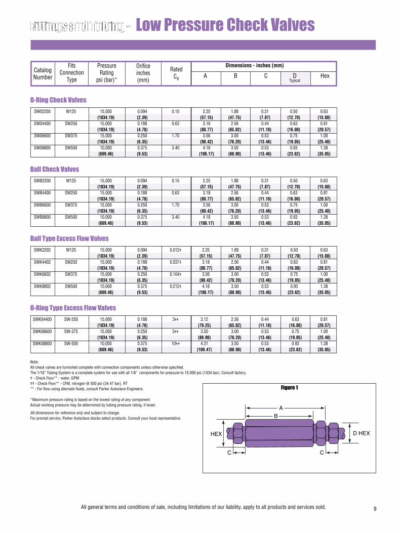
O-Ring Check Valves SW02200 W125 15,000 0.094 0.15 2.25 1.88 0.31 0.50 0.63 (1034.19) (2.39) (57.15) (47.75) (7.87) (12.70) (15.88) SW04400 SW250 15,000 0.188 0.63 3.18 2.56 0.44 0.63 0.81 (1034.19) (4.78) (80.77) (65.02) (11.18) (16.00) (20.57) SW06600 SW375 15,000 0.250 1.70 3.56 3.00 0.53 0.75 1.00 (1034.19) (6.35) (90.42) (76.20) (13.46) (19.05) (25.40) SW08800 SW500 10,000 0.375 3.40 4.18 3.50 0.53 0.93 1.38 (689.46) (9.53) (106.17) (88.90) (13.46) (23.62) (35.05)
Dimensions - inches (mm)
Fittings and Tubing - Low Pressure Check Valves
Catalog Number
Fits Connection
Type
Orifice inches (mm)
Pressure Rating
psi (bar)*
Rated Cv A B C D Hex
Typical
Ball Check Valves SWB2200 W125 15,000 0.094 0.15 2.25 1.88 0.31 0.50 0.63 (1034.19) (2.39) (57.15) (47.75) (7.87) (12.70) (15.88) SWB4400 SW250 15,000 0.188 0.63 3.18 2.56 0.44 0.63 0.81 (1034.19) (4.78) (80.77) (65.02) (11.18) (16.00) (20.57) SWB6600 SW375 15,000 0.250 1.70 3.56 3.00 0.53 0.75 1.00 (1034.19) (6.35) (90.42) (76.20) (13.46) (19.05) (25.40) SWB8800 SW500 10,000 0.375 3.40 4.18 3.50 0.53 0.93 1.38 (689.46) (9.53) (106.17) (88.90) (13.46) (23.62) (35.05)
Ball Type Excess Flow Valves SWK2202 W125 15,000 0.094 0.012= 2.25 1.88 0.31 0.50 0.63 (1034.19) (2.39) (57.15) (47.75) (7.87) (12.70) (15.88) SWK4402 SW250 15,000 0.188 0.037= 3.18 2.56 0.44 0.63 0.81 (1034.19) (4.78) (80.77) (65.02) (11.18) (16.00) (20.57) SWK6602 SW375 15,000 0.250 0.104= 3.56 3.00 0.53 0.75 1.00 (1034.19) (6.35) (90.42) (76.20) (13.46) (19.05) (25.40) SWK8802 SW500 10,000 0.375 0.212= 4.18 3.50 0.53 0.93 1.38 (689.46) (9.53) (106.17) (88.90) (13.46) (23.62) (35.05)
O-Ring Type Excess Flow Valves SWK04400 SW-250 15,000 0.188 3== 3.12 2.56 0.44 0.63 0.81 (1034.19) (4.78) (79.25) (65.02) (11.18) (16.00) (20.57) SWK06600 SW-375 15,000 0.250 5== 3.50 3.00 0.53 0.75 1.00 (1034.19) (6.35) (88.90) (76.20) (13.46) (19.05) (25.40) SWK08800 SW-500 10,000 0.375 10== 4.31 3.50 0.53 0.93 1.38 (689.46) (9.53) (109.47) (88.90) (13.46) (23.62) (35.05)
Figure 1
HEX
C
B
A
C
D HEX
Note: All check valves are furnished complete with connection components unless otherwise specified. The 1/16” Tubing System is a complete system for use with all 1/8” components for pressure to 15,000 psi (1034 bar). Consult factory.= - Check Flow** - water, GPM== - Check Flow** - CFM, nitrogen @ 500 psi (34.47 bar), RT** - For flow using alternate fluids, consult Parker Autoclave Engineers.
*Maximum pressure rating is based on the lowest rating of any component. Actual working pressure may be determined by tubing pressure rating, if lower.
All dimensions for reference only and subject to change.For prompt service, Parker Autoclave stocks select products. Consult your local representative.
All general terms and conditions of sale, including limitations of our liability, apply to all products and services sold. 9
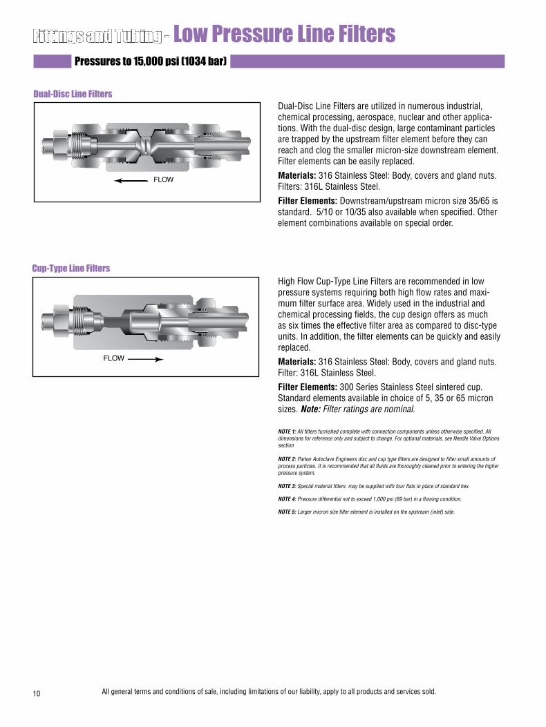
Fittings and Tubing - Low Pressure Line FiltersPressures to 15,000 psi (1034 bar)
Dual-Disc Line Filters are utilized in numerous industrial, chemical processing, aerospace, nuclear and other applica-tions. With the dual-disc design, large contaminant particles are trapped by the upstream filter element before they can reach and clog the smaller micron-size downstream element. Filter elements can be easily replaced.
Materials: 316 Stainless Steel: Body, covers and gland nuts. Filters: 316L Stainless Steel.
Filter Elements: Downstream/upstream micron size 35/65 is standard. 5/10 or 10/35 also available when specified. Other element combinations available on special order.
High Flow Cup-Type Line Filters are recommended in low pressure systems requiring both high flow rates and maxi-mum filter surface area. Widely used in the industrial and chemical processing fields, the cup design offers as much as six times the effective filter area as compared to disc-type units. In addition, the filter elements can be quickly and easily replaced.
Materials: 316 Stainless Steel: Body, covers and gland nuts. Filter: 316L Stainless Steel.
Filter Elements: 300 Series Stainless Steel sintered cup. Standard elements available in choice of 5, 35 or 65 micron sizes. Note: Filter ratings are nominal.
NOTE 1: All filters furnished complete with connection components unless otherwise specified. All dimensions for reference only and subject to change. For optional materials, see Needle Valve Options section
NOTE 2: Parker Autoclave Engineers disc and cup type filters are designed to filter small amounts of process particles. It is recommended that all fluids are thoroughly cleaned prior to entering the higher pressure system.
NOTE 3: Special material filters may be supplied with four flats in place of standard hex.
NOTE 4: Pressure differential not to exceed 1,000 psi (69 bar) in a flowing condition.
NOTE 5: Larger micron size filter element is installed on the upstream (inlet) side.
Dual-Disc Line Filters
FLOW
Cup-Type Line Filters
FLOW
10 All general terms and conditions of sale, including limitations of our liability, apply to all products and services sold.

Dimensions - inches (mm)Catalog Number
Orifice inches (mm)
Pressure Rating
psi (bar)*
Micron Size** A B C D Hex
Typical
Effective Filter
ElementArea
in.2 (mm2)
Connection Size and
Type
Fittings and Tubing - Low Pressure Line Filters
SWF4-5 5
SWF4-35 35
SWF4-65 65
SWF6-5 5
SWF6-35 35
SWF6-65 65
SWF8-5 5
SWF8-35 35
SWF8-65 65
** Larger micron size filter element is installed on upstream (inlet) side. All filters furnished complete with connection components unless otherwise specified.
Other micron sizes available on special order. Change last digits of the catalog number accordingly. For optional materials, see Needle Valve Options section.
The 1/16” Tubing System is a complete system for use with all 1/8” components for pressure to 15,000 psi (1034 bar). Consult factory.
Dual-Disc Line Filters Cup-Type Line Filters
Dual-Disc Line Filters SLF2200 35/65
SLF2200-5/10 5/10
SLF2200-10/35 10/35
SLF4400 35/65
SLF4400-5/10 5/10
SLF4400-10/35 10/35
SLF6600 35/65
SLF6600-5/10 5/10
SLF6600-10/35 10/35
SLF8800 35/65
SLF8800-5/10 5/10
SLF8800-10/35 10/35
15,000 .094 W125 .06 2.31 1.25 0.31 .50 0.62 (1034.19) (2.39) (38.70) (58.67) (31.75) (7.87) (12.70) (15.74)
15,000 .125 SW250 .15 2.94 1.68 0.44 .63 0.81 (1034.19) (3.18) (96.77) (75.56) (42.67) (11.17) (15.88) (20.57)
15,000 .125 SW375 .15 2.94 1.68 0.53 .75 1.00 (1034.19) (3.18) (96.77) (75.56) (42.67) (13.46) (19.05) (25.40)
10,000 .188 SW500 .25 3.56 1.94 0.53 .93 1.18 (689.46) (4.78) (161.29) (90.42) (49.27) (13.46) (23.62) (29.97)
Cup-Type Line Filters
15,000 .188 SW250 0.81 3.18 2.56 0.44 0.63 0.81 (1034.19) (4.78) (522.57) (80.77) (65.02) (11.17) (15.88) (20.57)
15,000 .312 SW375 0.81 3.56 3.00 0.53 0.75 1.00 (1034.19) (7.92) (522.57) (90.42) (76.20) (13.46) (19.05) (25.40)
10,000 .438 SW500 1.53 4.18 3.50 0.53 .93 1.38 (689.46) (11.13) (987.09) (106.17) (88.90) (13.46) (23.62) (35.05)
HEX
C B
AD
HEXC
*Maximum pressure rating is based on the lowest rating of any component. Actual working pressure may be determined by tubing pressure rating, if lower.
All dimensions for reference only and subject to change.For prompt service, Parker Autoclave Engineers stocks select products. Consult your local representative.
All general terms and conditions of sale, including limitations of our liability, apply to all products and services sold. 11
HEX
B
AD
HEXCC

02-0123SE January2013© 2013 Parker Hannifin Corporation | Autoclave Engineers is a registered trademark of the Parker Hannifin Corporation
Parker Hannifin Manufacturing Ltd. Instrumentation Products Division, Europe Industrial Estate WhitemillWexford, Republic of IrelandPH: 353 53 914 1566FAX: 353 53 914 1582
Instrumentation Products DivisionAutoclave Engineers Operation8325 Hessinger DriveErie, Pennsylvania 16509-4679 USAPH: 814-860-5700 FAX: 814-860-5811www.autoclave.com
WARNING
FAILURE, IMPROPER SELECTION OR IMPROPER USE OF THE PRODUCTS AND/OR SYSTEMS DESCRIBED HEREIN OR RELATED ITEMS CAN CAUSE DEATH, PERSONAL INJURY AND PROPERTY DAMAGE.This document and other information from Parker Hannifin Corporation, its subsidiaries and authorized distributors provide product and/or system options for further investigation by users having technical expertise. It is important that you analyze all aspects of your application and review the information concerning the product or system in the current product catalog. Due to the variety of operating conditions and applications for these products or systems, the user, through its own analysis and testing, is solely responsible for making the final selection of the products and systems and assuring that all performance, safety and warning requirements of the application are met. The products described herein, including without limitation, product features, specifications, designs, availability and pricing, are subject to change by Parker Hannifin Corporation and its subsidiaries at any time without notice.
Offer of Sale
The items described in this document are available for sale by Parker Hannifin Corporation, its subsidiaries or its authorized distributors. Any sale contract entered by Parker will be governed by the provisions stated in Parker's standard terms and conditions of sale (copy available upon request).
ISO-9001 Certified
Caution! Do not mix or interchange parts or tubing with those of other manufacturers. Doing so is unsafe and will void warranty.
Caution! Parker Autoclave Engineers Valves, Fittings and Tools are not designed to work with common commercial instrument tubing and will only work with tubing built to Parker Autoclave Engineers AES Specifications. Failure to do so will void warranty.

Since 1945 Parker Autoclave Engineers has designed and built premium quality valves, fittings and tubing. This commitment to engineering and manufacturing excellence has earned Parker Autoclave Engineers a reputation for reliable, efficient product perfor-mance. Parker Autoclave Engineers has long been established as the world leader in high pressure fluid handling components for the chemical/petrochemi-cal, research, and oil and gas industries.
Medium Pressure Fittings, Tubing and Nipples Features:
• Coned-and-Threaded Connection.
• Available sizes are 1/4", 3/8", 9/16", 3/4", 1" and 1-1/2".
• Fittings manufactured from cold worked 316 stainless steel.
• Tubing is manufactured from dual rated 316/316L and 304/304L cold worked stainless steel.
• Operating Temperatures from -423°F (-252°C) to 1200°F (649°C).
• Anti-vibration connection components available.
• All items available in special material.
The medium pressure series uses Parker Autoclave Engineers medium pressure connection. This coned-and-threaded connection features orifice sizes to match the high flow characteristics of this series.
Pressures to 20,000 psi (1379 bar)
Medium PressureFittings, Tubing & Nipples
Fittings ,Tubing & Nipples - Medium Pressure
www.autoclave.com
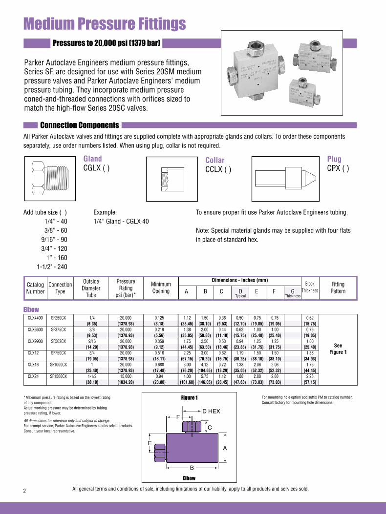
Elbow CLX4400 SF250CX 1/4 20,000 0.125 1.12 1.50 0.38 0.50 0.75 0.75 0.62 (6.35) (1378.93) (3.18) (28.45) (38.10) (9.53) (12.70) (19.05) (19.05) (15.75) CLX6600 SF375CX 3/8 20,000 0.219 1.38 2.00 0.44 0.62 1.00 1.00 0.75 (9.53) (1378.93) (5.56) (35.05) (50.80) (11.10) (15.75) (25.40) (25.40) (19.05) CLX9900 SF562CX 9/16 20,000 0.359 1.75 2.50 0.53 0.94 1.25 1.25 1.00 (14.29) (1378.93) (9.12) (44.45) (63.50) (13.46) (23.88) (31.75) (31.75) (25.40) CLX12 SF750CX 3/4 20,000 0.516 2.25 3.00 0.62 1.19 1.50 1.50 1.38 (19.05) (1378.93) (13.11) (57.15) (76.20) (15.75) (30.23) (38.10) (38.10) (34.93) CLX16 SF1000CX 1 20,000 0.688 3.00 4.12 0.72 1.38 2.06 2.06 1.75 (25.40) (1378.93) (17.48) (76.20) (104.65) (18.29) (35.05) (52.32) (52.32) (44.45) CLX24 SF1500CX 1-1/2 15,000 0.94 4.00 5.75 1.12 1.88 2.88 2.88 2.25 (38.10) (1034.20) (23.80) (101.60) (146.05) (28.45) (47.63) (73.03) (73.03) (57.15)
Dimensions - inches (mm)
Medium Pressure FittingsPressures to 20,000 psi (1379 bar)
See Figure 1
Parker Autoclave Engineers medium pressure fittings, Series SF, are designed for use with Series 20SM medium pressure valves and Parker Autoclave Engineers' medium pressure tubing. They incorporate medium pressure coned-and-threaded connections with orifices sized to match the high-flow Series 20SC valves.
Connection ComponentsAll Parker Autoclave valves and fittings are supplied complete with appropriate glands and collars. To order these components separately, use order numbers listed. When using plug, collar is not required.
To ensure proper fit use Parker Autoclave Engineers tubing.
Note: Special material glands may be supplied with four flats in place of standard hex.
Gland CGLX ( )
Add tube size ( ) Example: 1/4” - 40 1/4” Gland - CGLX 40 3/8” - 60 9/16” - 90 3/4” - 120 1” - 160 1-1/2" - 240
Catalog Number
Connection Type
Outside Diameter
Tube
Pressure Rating
psi (bar)*
Minimum Opening
Block Thickness
Fitting Pattern A B C D E F G
Typical Thickness
Elbow
Figure 1
D HEXF
C
A
B
E
Plug CPX ( )
Collar CCLX ( )
*Maximum pressure rating is based on the lowest rating of any component. Actual working pressure may be determined by tubing pressure rating, if lower.
All dimensions for reference only and subject to change.For prompt service, Parker Autoclave Engineers stocks select products. Consult your local representative.
2 All general terms and conditions of sale, including limitations of our liability, apply to all products and services sold.
For mounting hole option add suffix PM to catalog number. Consult factory for mounting hole dimensions.

Dimensions - inches (mm)Catalog Number
Connection Type
Outside Diameter
Tube
Pressure Rating
psi (bar)*
Minimum Opening
Block Thickness
Fitting Pattern A B C D E F G
Typical Thickness
Tee CTX4440 SF250CX 1/4 20,000 0.125 1.12 1.50 0.38 0.50 0.75 0.75 0.62 (6.35) (1378.93) (3.18) (28.45) (38.10) (9.53) (12.70) (19.05) (19.05) (15.75) CTX6660 SF375CX 3/8 20,000 0.219 1.38 2.00 0.44 0.62 1.00 1.00 0.75 (9.53) (1378.93) (5.56) (35.05) (50.80) (11.10) (15.75) (25.40) (25.40) (19.05) CTX9990 SF562CX 9/16 20,000 0.359 1.75 2.50 0.53 0.94 1.25 1.25 1.00 (14.29) (1378.93) (9.12) (44.45) (63.50) (13.46) (23.88) (31.75) (31.75) (25.40) CTX12 SF750CX 3/4 20,000 0.516 2.25 3.00 0.62 1.19 1.50 1.50 1.38 (19.05) (1378.93) (13.11) (57.15) (76.20) (15.75) (30.23) (38.10) (38.10) (34.93) CTX16 SF1000CX 1 20,000 0.688 3.00 4.12 0.72 1.38 2.06 2.06 1.75 (25.40) (1378.93) (17.48) (76.20) (104.65) (18.29) (35.05) (52.32) (52.32) (44.45) CTX24 SF1500CX 1-1/2 15,000 0.94 4.00 5.75 1.12 1.88 2.88 2.88 2.25 (38.10) (1034.20) (23.80) (101.60) (146.05) (28.45) (47.63) (73.03) (73.03) (57.15)
See Figure 2
Cross CXX4444 SF250CX 1/4 20,000 0.125 1.50 1.50 0.38 0.50 0.75 0.75 0.62 (6.35) (1378.93) (3.18) (38.10) (38.10) (9.53) (12.70) (19.05) (19.05) (15.75) CXX6666 SF375CX 3/8 20,000 0.219 2.00 2.00 0.44 0.62 1.00 1.00 0.75 (9.53) (1378.93) (5.56) (50.80) (50.80) (11.10) (15.75) (25.40) (25.40) (19.05) CXX9999 SF562CX 9/16 20,000 0.359 2.50 2.50 0.53 0.94 1.25 1.25 1.00 (14.29) (1378.93) (9.12) (63.50) (63.50) (13.46) (23.88) (31.75) (31.75) (25.40) CXX12 SF750CX 3/4 20,000 0.516 3.00 3.00 0.62 1.19 1.50 1.50 1.38 (19.05) (1378.93) (13.11) (76.20) (76.20) (15.75) (30.23) (38.10) (38.10) (34.93) CXX16 SF1000CX 1 20,000 0.688 4.12 4.12 0.72 1.38 2.06 2.06 1.75 (25.40) (1378.93) (17.48) (104.65) (104.65) (18.29) (35.05) (52.32) (52.32) (44.45) CXX24 SF1500CX 1-1/2 15,000 0.94 5.75 5.75 1.12 1.88 2.88 2.88 2.25 (38.10) (1034.20) (23.80) (146.05) (146.05) (28.45) (47.63) (73.03) (73.03) (57.15)
See Figure 3
Cross
Figure 3
D HEXF
C
A
B
E
Tee
Figure 2
D HEXF
C
A
B
E
*Maximum pressure rating is based on the lowest rating of any component. Actual working pressure may be determined by tubing pressure rating, if lower.
All dimensions for reference only and subject to change.For prompt service, Parker Autoclave Engineers stocks select products. Consult your local representative.
All general terms and conditions of sale, including limitations of our liability, apply to all products and services sold. 3
For mounting hole option add suffix PM to catalog number. Consult factory for mounting hole dimensions.

Straight Coupling / Union Coupling
Figure 4
Bulkhead Coupling
Figure 5
Dimensions - inches (mm)Catalog Number
Connection Type
Outside Diameter
Tube
Pressure Rating
psi (bar)*
Minimum Opening
Block Thickness
Fitting Pattern A B C D E F G
Typical Thickness
Straight Coupling / Union Coupling 20FX4466 SF250CX 1/4 20,000 0.125 0.62 1.62 0.38 0.50 Straight 20UFX4466 (6.35) (1378.93) (3.18) (15.75) (41.15) (9.53) (12.70) Union 20FX6666 SF375CX 3/8 20,000 0.219 0.75 1.75 0.44 0.62 Straight 20UFX6666 (9.53) (1378.93) (5.56) (19.05) (44.45) (11.10) (15.75) Union 20FX9966 SF562CX 9/16 20,000 0.359 1.00 2.12 0.53 0.94 Straight 20UFX9966 (14.29) (1378.93) (9.12) (25.40) (53.85) (13.46) (23.88) Union 20FX12 SF750CX 3/4 20,000 0.516 1.38 2.50 0.62 1.19 Straight 20UFX12 (19.05) (1378.93) (13.11) (35.05) (63.50) (15.75) (30.23) Union 20FX16 SF1000CX 1 20,000 0.688 1.75 3.50 0.72 1.38 Straight 20UFX16 (25.40) (1378.93) (17.48) (44.45) (88.90) (18.29) (35.05) Union 15FX24 SF1500CX 1-1/2 15,000 0.94 2.25 5.00 1.12 1.88 Straight 15UFX24 (38.10) (1034.20) (23.80) (25.15) (127.00) (28.45) (47.63) Union
See Figure 4
Bulkhead Coupling 20BFX4466 SF250CX 1/4 20,000 0.125 0.81 1.88 0.38 0.50 0.53 1.00 0.38 (6.35) (1378.93) (3.18) (20.57) (47.75) (9.53) (12.70) (13.46) (25.40) (9.53) 20BFX6666 SF375CX 3/8 20,000 0.219 0.94 2.00 0.44 0.62 0.62 1.00 0.38 (9.53) (1378.93) (5.56) (23.88) (50.80) (11.10) (15.75) (15.75) (25.40) (9.53) 20BFX9966 SF562CX 9/16 20,000 0.359 1.12 2.38 0.53 0.94 0.78 1.38 0.38 (14.29) (1378.93) (9.12) (28.45) (60.45) (13.46) (23.88) (19.81) (35.05) (9.53) 20BFX12 SF750CX 3/4 20,000 0.516 1.69 2.62 0.62 1.19 0.91 1.88 0.38 (19.05) (1378.93) (13.11) (42.93) (66.55) (15.75) (30.23) (23.11) (47.75) (9.53) 20BFX16 SF1000CX 1 20,000 0.688 1.94 3.50 0.72 1.38 1.50 1.88+ 0.38 (25.40) (1378.93) (17.48) (49.28) (88.90) (18.29) (35.05) (38.10) (47.75) (9.53) 15BFX24 SF1500CX 1-1/2 15,000 0.94 2.44 5.00 1.12 1.88 2.00 2.50+ 0.38 (38.10) (1034.20) (23.80) (61.85) (127.00) (28.45) (47.63) (50.80) (63.50) (9.53)
See Figure 5
*Maximum pressure rating is based on the lowest rating of any component. Actual working pressure may be determined by tubing pressure rating, if lower.+ distance across flats
All dimensions for reference only and subject to change.For prompt service, Parker Autoclave Engineers stocks select products. Consult your local representative.
4 All general terms and conditions of sale, including limitations of our liability, apply to all products and services sold.
Union Couplings are designed with a removable seat insert allowing disassembly and tubing removal without the necessity of loosening other items in a line.
DHEX
CB
A HEX
G MAX
CB
E
AD
HEXF
HEX
(A=Panel hole drill size)
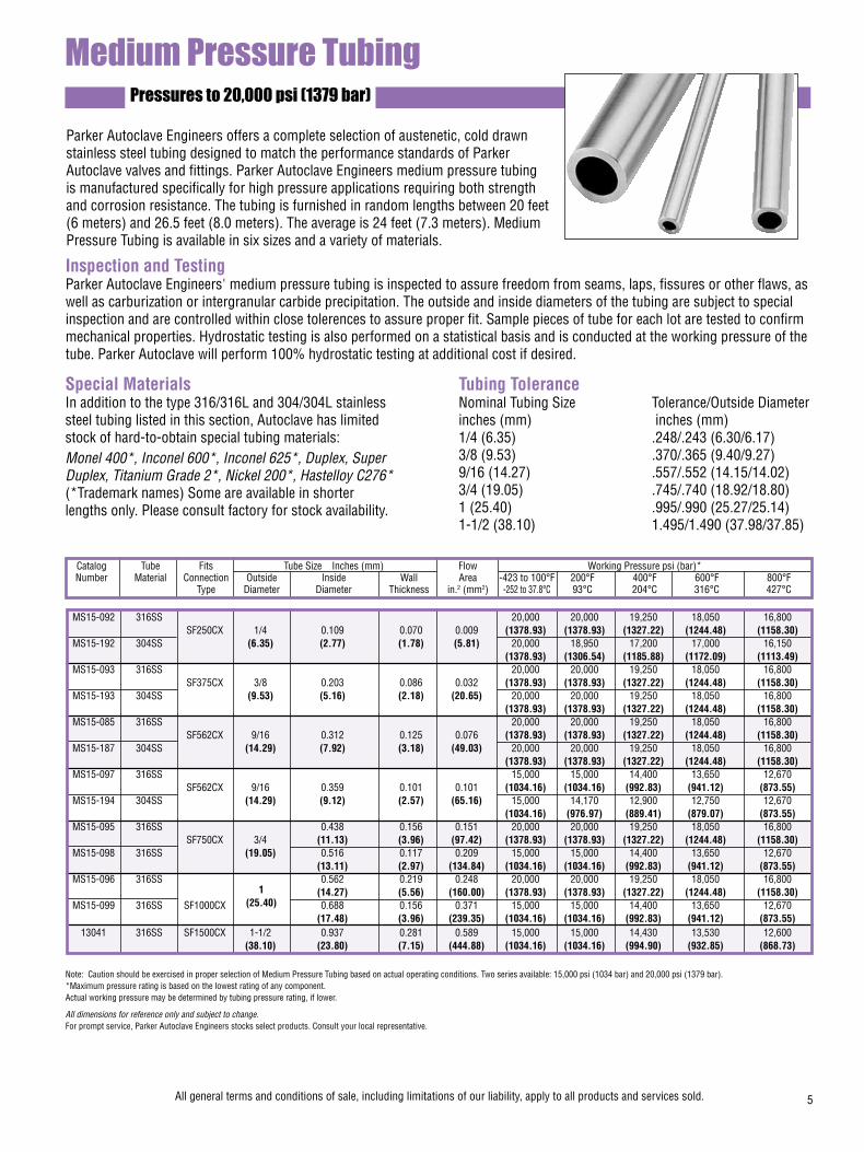
Pressures to 20,000 psi (1379 bar)
Parker Autoclave Engineers offers a complete selection of austenetic, cold drawn stainless steel tubing designed to match the performance standards of Parker Autoclave valves and fittings. Parker Autoclave Engineers medium pressure tubing is manufactured specifically for high pressure applications requiring both strength and corrosion resistance. The tubing is furnished in random lengths between 20 feet (6 meters) and 26.5 feet (8.0 meters). The average is 24 feet (7.3 meters). Medium Pressure Tubing is available in six sizes and a variety of materials.
Catalog Tube Fits Tube Size Inches (mm) Flow Working Pressure psi (bar)* Number Material Connection Outside Inside Wall Area -423 to 100°F 200°F 400°F 600°F 800°F Type Diameter Diameter Thickness in.2 (mm2) -252 to 37.8°C 93°C 204°C 316°C 427°C
Inspection and TestingParker Autoclave Engineers' medium pressure tubing is inspected to assure freedom from seams, laps, fissures or other flaws, as well as carburization or intergranular carbide precipitation. The outside and inside diameters of the tubing are subject to special inspection and are controlled within close tolerences to assure proper fit. Sample pieces of tube for each lot are tested to confirm mechanical properties. Hydrostatic testing is also performed on a statistical basis and is conducted at the working pressure of the tube. Parker Autoclave will perform 100% hydrostatic testing at additional cost if desired.
Special MaterialsIn addition to the type 316/316L and 304/304L stainless steel tubing listed in this section, Autoclave has limited stock of hard-to-obtain special tubing materials: Monel 400*, Inconel 600*, Inconel 625*, Duplex, SuperDuplex, Titanium Grade 2*, Nickel 200*, Hastelloy C276*(*Trademark names) Some are available in shorterlengths only. Please consult factory for stock availability.
Tubing ToleranceNominal Tubing Size Tolerance/Outside Diameterinches (mm) inches (mm)1/4 (6.35) .248/.243 (6.30/6.17)3/8 (9.53) .370/.365 (9.40/9.27)9/16 (14.27) .557/.552 (14.15/14.02)3/4 (19.05) .745/.740 (18.92/18.80)1 (25.40) .995/.990 (25.27/25.14)1-1/2 (38.10) 1.495/1.490 (37.98/37.85)
Medium Pressure Tubing
Note: Caution should be exercised in proper selection of Medium Pressure Tubing based on actual operating conditions. Two series available: 15,000 psi (1034 bar) and 20,000 psi (1379 bar).*Maximum pressure rating is based on the lowest rating of any component. Actual working pressure may be determined by tubing pressure rating, if lower.
All dimensions for reference only and subject to change.For prompt service, Parker Autoclave Engineers stocks select products. Consult your local representative.
All general terms and conditions of sale, including limitations of our liability, apply to all products and services sold. 5
MS15-092 316SS 20,000 20,000 19,250 18,050 16,800 SF250CX 1/4 0.109 0.070 0.009 (1378.93) (1378.93) (1327.22) (1244.48) (1158.30) MS15-192 304SS (6.35) (2.77) (1.78) (5.81) 20,000 18,950 17,200 17,000 16,150 (1378.93) (1306.54) (1185.88) (1172.09) (1113.49) MS15-093 316SS 20,000 20,000 19,250 18,050 16,800 SF375CX 3/8 0.203 0.086 0.032 (1378.93) (1378.93) (1327.22) (1244.48) (1158.30) MS15-193 304SS (9.53) (5.16) (2.18) (20.65) 20,000 20,000 19,250 18,050 16,800 (1378.93) (1378.93) (1327.22) (1244.48) (1158.30) MS15-085 316SS 20,000 20,000 19,250 18,050 16,800 SF562CX 9/16 0.312 0.125 0.076 (1378.93) (1378.93) (1327.22) (1244.48) (1158.30) MS15-187 304SS (14.29) (7.92) (3.18) (49.03) 20,000 20,000 19,250 18,050 16,800 (1378.93) (1378.93) (1327.22) (1244.48) (1158.30) MS15-097 316SS 15,000 15,000 14,400 13,650 12,670 SF562CX 9/16 0.359 0.101 0.101 (1034.16) (1034.16) (992.83) (941.12) (873.55) MS15-194 304SS (14.29) (9.12) (2.57) (65.16) 15,000 14,170 12,900 12,750 12,670 (1034.16) (976.97) (889.41) (879.07) (873.55) MS15-095 316SS 0.438 0.156 0.151 20,000 20,000 19,250 18,050 16,800 SF750CX 3/4 (11.13) (3.96) (97.42) (1378.93) (1378.93) (1327.22) (1244.48) (1158.30) MS15-098 316SS (19.05) 0.516 0.117 0.209 15,000 15,000 14,400 13,650 12,670 (13.11) (2.97) (134.84) (1034.16) (1034.16) (992.83) (941.12) (873.55) MS15-096 316SS 0.562 0.219 0.248 20,000 20,000 19,250 18,050 16,800 (14.27) (5.56) (160.00) (1378.93) (1378.93) (1327.22) (1244.48) (1158.30) MS15-099 316SS SF1000CX 0.688 0.156 0.371 15,000 15,000 14,400 13,650 12,670 (17.48) (3.96) (239.35) (1034.16) (1034.16) (992.83) (941.12) (873.55) 13041 316SS SF1500CX 1-1/2 0.937 0.281 0.589 15,000 15,000 14,430 13,530 12,600 (38.10) (23.80) (7.15) (444.88) (1034.16) (1034.16) (994.90) (932.85) (868.73)
1(25.40)
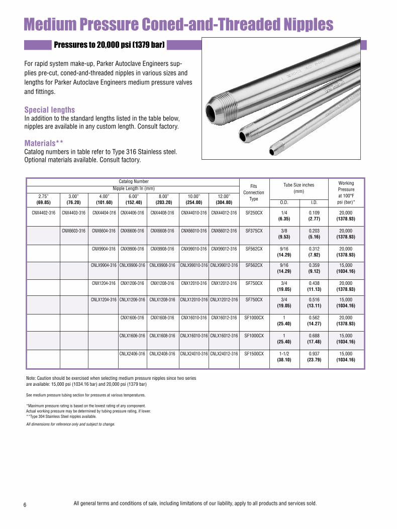
FitsConnection
Type
WorkingPressureat 100°F
psi (bar)*
Tube Size inches(mm)
Pressures to 20,000 psi (1379 bar)
Medium Pressure Coned-and-Threaded Nipples
For rapid system make-up, Parker Autoclave Engineers sup-plies pre-cut, coned-and-threaded nipples in various sizes and lengths for Parker Autoclave Engineers medium pressure valves and fittings.
Special lengthsIn addition to the standard lengths listed in the table below, nipples are available in any custom length. Consult factory.
Materials**Catalog numbers in table refer to Type 316 Stainless steel. Optional materials available. Consult factory.
Note: Caution should be exercised when selecting medium pressure nipples since two series are available: 15,000 psi (1034.16 bar) and 20,000 psi (1379 bar)
See medium pressure tubing section for pressures at various temperatures.
*Maximum pressure rating is based on the lowest rating of any component. Actual working pressure may be determined by tubing pressure rating, if lower.**Type 304 Stainless Steel nipples available.
All dimensions for reference only and subject to change.
6 All general terms and conditions of sale, including limitations of our liability, apply to all products and services sold.
Catalog Number Nipple Length In (mm)
2.75” 3.00” 4.00” 6.00” 8.00” 10.00” 12.00” (69.85) (76.20) (101.60) (152.40) (203.20) (254.00) (304.80) O.D. I.D.
CNX4402-316 CNX4403-316 CNX4404-316 CNX4406-316 CNX4408-316 CNX44010-316 CNX44012-316 SF250CX 1/4 0.109 20,000 (6.35) (2.77) (1378.93)
CNX6603-316 CNX6604-316 CNX6606-316 CNX6608-316 CNX66010-316 CNX66012-316 SF375CX 3/8 0.203 20,000 (9.53) (5.16) (1378.93)
CNX9904-316 CNX9906-316 CNX9908-316 CNX99010-316 CNX99012-316 SF562CX 9/16 0.312 20,000 (14.29) (7.92) (1378.93)
CNLX9904-316 CNLX9906-316 CNLX9908-316 CNLX99010-316 CNLX99012-316 SF562CX 9/16 0.359 15,000 (14.29) (9.12) (1034.16)
CNX1204-316 CNX1206-316 CNX1208-316 CNX12010-316 CNX12012-316 SF750CX 3/4 0.438 20,000 (19.05) (11.13) (1378.93)
CNLX1204-316 CNLX1206-316 CNLX1208-316 CNLX12010-316 CNLX12012-316 SF750CX 3/4 0.516 15,000 (19.05) (13.11) (1034.16)
CNX1606-316 CNX1608-316 CNX16010-316 CNX16012-316 SF1000CX 1 0.562 20,000 (25.40) (14.27) (1378.93)
CNLX1606-316 CNLX1608-316 CNLX16010-316 CNLX16012-316 SF1000CX 1 0.688 15,000 (25.40) (17.48) (1034.16)
CNLX2406-316 CNLX2408-316 CNLX24010-316 CNLX24012-316 SF1500CX 1-1/2 0.937 15,000 (38.10) (23.79) (1034.16)

Medium Pressure Check ValvesPressures to 20,000 (1379 bar)
Provides unidirectional flow and tight shut-off for liquids and gas with high reliability. When differential drops below crack-ing pressure*, valve shuts off. (Not for use as relief valve.)
Materials: 316 Stainless Steel: body, cover, poppet, cover gland. 300 Series Stainless Steel: springStandard O-ring: Viton, for operation to 400° F (204°C). Buna-N or PTFE available for 250°F (121°C) or 400°F (204°C) respectively; specify when ordering.
*Cracking Pressure: 20 psi (1.38 bar) ±30%. Springs for higher cracking pressures (up to 100 psi (6.89 bar)) available on special order for O-ring style check valves only.
Prevents reverse flow where leak-tight shut-off is not manda-tory. When differential drops below cracking pressure, valve closes. With all-metal components, valve can be used up to 1200°F (649°C). See Technical Information section for con-nection temperature limitations. (Not for use as a relief valve.)
The ball and poppet are an integral design to assure positive, in-line seating without “chatter”. Poppet is designed essentially for axial flow with minimum pressure drop.
Materials: 316 Stainless Steel: body, cover, ball poppet, cover gland. 300 Series Stainless Steel: ball, spring.
Protects pressure gauges and pressure instrumentation from surges in flow or sudden venting in the event of line failure.
Materials: 316 Stainless Steel: body, cover, sleeve, cover gland. 300 Series Stainless Steel: ball.
Vertical Installation: Since this type of check valve employs a non-spring loaded ball, valve MUST be installed in VERTICAL position with arrow on valve body pointing UP. (cover gland up).
Resetting Valve: Equalize the pressure across the ball. The ball will drop and reset automatically.
O-Ring Check Valves
Ball Check Valves
Ball Type Excess Flow Valves
CAUTION: While testing has shown O-Rings to provide satisfactory service life, both cyclic and shelf life may vary widely with differing service conditions, properties of reactants, pressure and temperature cycling and age of the O-ring. FREQUENT INSPECTIONS SHOULD BE MADE to detect any deterioration, and O-rings replaced as required.
CAUTION: See Tubing section for proper selection of tubing. NOTE: For optional material see Needle Valve Options section.
NOTE: Special material check valves may be supplied with four flats in place of standard hex.
FLO
W
(Vertical Installation O
nly)
All general terms and conditions of sale, including limitations of our liability, apply to all products and services sold. 7
FLOW
Minimum operating temperature for standard o-ring check valves 0°F (-17.8°C).For low temperature option to -423°F (-252°C) add suffix LTTO (Low temperature spring & PTFE o-ring).
Minimum operating temperature for standard ball check valves -110°F (-79°C).For low temperature option to -423°F (-252°C) add suffix LT (Low temperature spring).
FLOW
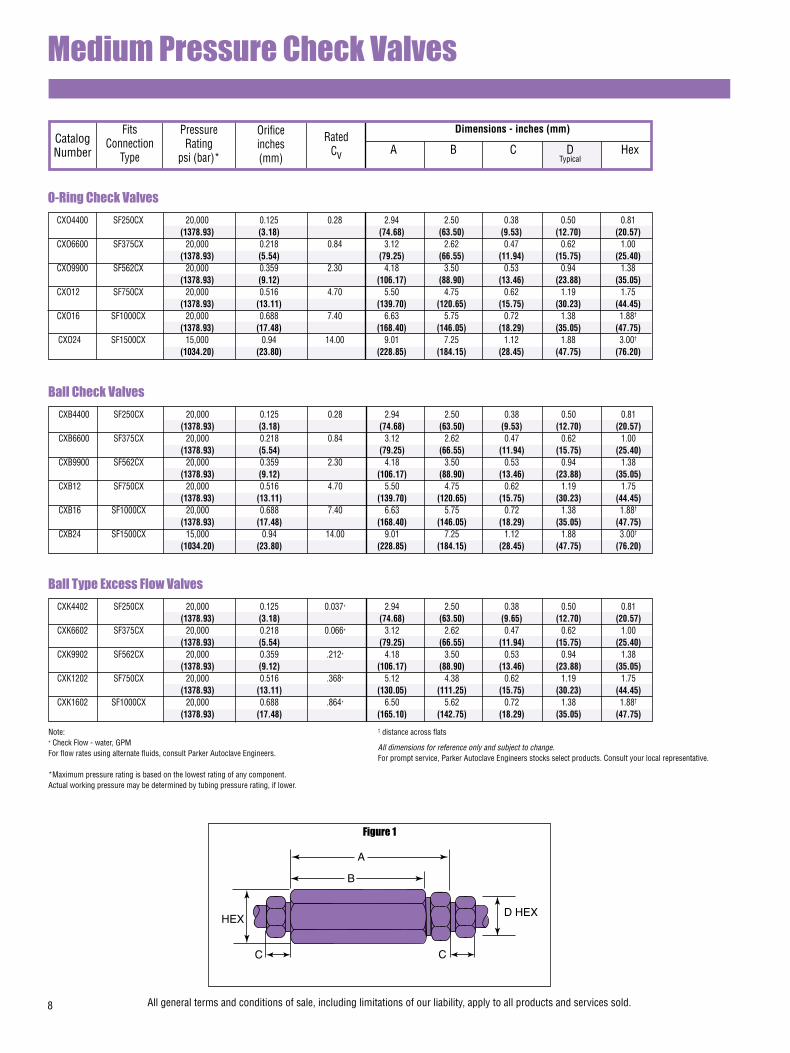
O-Ring Check Valves CXO4400 SF250CX 20,000 0.125 0.28 2.94 2.50 0.38 0.50 0.81 (1378.93) (3.18) (74.68) (63.50) (9.53) (12.70) (20.57) CXO6600 SF375CX 20,000 0.218 0.84 3.12 2.62 0.47 0.62 1.00 (1378.93) (5.54) (79.25) (66.55) (11.94) (15.75) (25.40) CXO9900 SF562CX 20,000 0.359 2.30 4.18 3.50 0.53 0.94 1.38 (1378.93) (9.12) (106.17) (88.90) (13.46) (23.88) (35.05) CXO12 SF750CX 20,000 0.516 4.70 5.50 4.75 0.62 1.19 1.75 (1378.93) (13.11) (139.70) (120.65) (15.75) (30.23) (44.45) CXO16 SF1000CX 20,000 0.688 7.40 6.63 5.75 0.72 1.38 1.88†
(1378.93) (17.48) (168.40) (146.05) (18.29) (35.05) (47.75) CXO24 SF1500CX 15,000 0.94 14.00 9.01 7.25 1.12 1.88 3.00†
(1034.20) (23.80) (228.85) (184.15) (28.45) (47.75) (76.20)
Dimensions - inches (mm)
Medium Pressure Check Valves
Catalog Number
Fits Connection
Type
Orifice inches (mm)
Pressure Rating
psi (bar)*
Rated Cv A B C D Hex
Typical
Figure 1
Ball Check Valves CXB4400 SF250CX 20,000 0.125 0.28 2.94 2.50 0.38 0.50 0.81 (1378.93) (3.18) (74.68) (63.50) (9.53) (12.70) (20.57) CXB6600 SF375CX 20,000 0.218 0.84 3.12 2.62 0.47 0.62 1.00 (1378.93) (5.54) (79.25) (66.55) (11.94) (15.75) (25.40) CXB9900 SF562CX 20,000 0.359 2.30 4.18 3.50 0.53 0.94 1.38 (1378.93) (9.12) (106.17) (88.90) (13.46) (23.88) (35.05) CXB12 SF750CX 20,000 0.516 4.70 5.50 4.75 0.62 1.19 1.75 (1378.93) (13.11) (139.70) (120.65) (15.75) (30.23) (44.45) CXB16 SF1000CX 20,000 0.688 7.40 6.63 5.75 0.72 1.38 1.88†
(1378.93) (17.48) (168.40) (146.05) (18.29) (35.05) (47.75) CXB24 SF1500CX 15,000 0.94 14.00 9.01 7.25 1.12 1.88 3.00†
(1034.20) (23.80) (228.85) (184.15) (28.45) (47.75) (76.20)
Ball Type Excess Flow Valves CXK4402 SF250CX 20,000 0.125 0.037+ 2.94 2.50 0.38 0.50 0.81 (1378.93) (3.18) (74.68) (63.50) (9.65) (12.70) (20.57) CXK6602 SF375CX 20,000 0.218 0.066+ 3.12 2.62 0.47 0.62 1.00 (1378.93) (5.54) (79.25) (66.55) (11.94) (15.75) (25.40) CXK9902 SF562CX 20,000 0.359 .212+ 4.18 3.50 0.53 0.94 1.38 (1378.93) (9.12) (106.17) (88.90) (13.46) (23.88) (35.05) CXK1202 SF750CX 20,000 0.516 .368+ 5.12 4.38 0.62 1.19 1.75 (1378.93) (13.11) (130.05) (111.25) (15.75) (30.23) (44.45) CXK1602 SF1000CX 20,000 0.688 .864+ 6.50 5.62 0.72 1.38 1.88† (1378.93) (17.48) (165.10) (142.75) (18.29) (35.05) (47.75)
Note: + Check Flow - water, GPMFor flow rates using alternate fluids, consult Parker Autoclave Engineers. *Maximum pressure rating is based on the lowest rating of any component. Actual working pressure may be determined by tubing pressure rating, if lower.
8 All general terms and conditions of sale, including limitations of our liability, apply to all products and services sold.
† distance across flats
All dimensions for reference only and subject to change.For prompt service, Parker Autoclave Engineers stocks select products. Consult your local representative.
HEX
C
B
A
C
D HEX
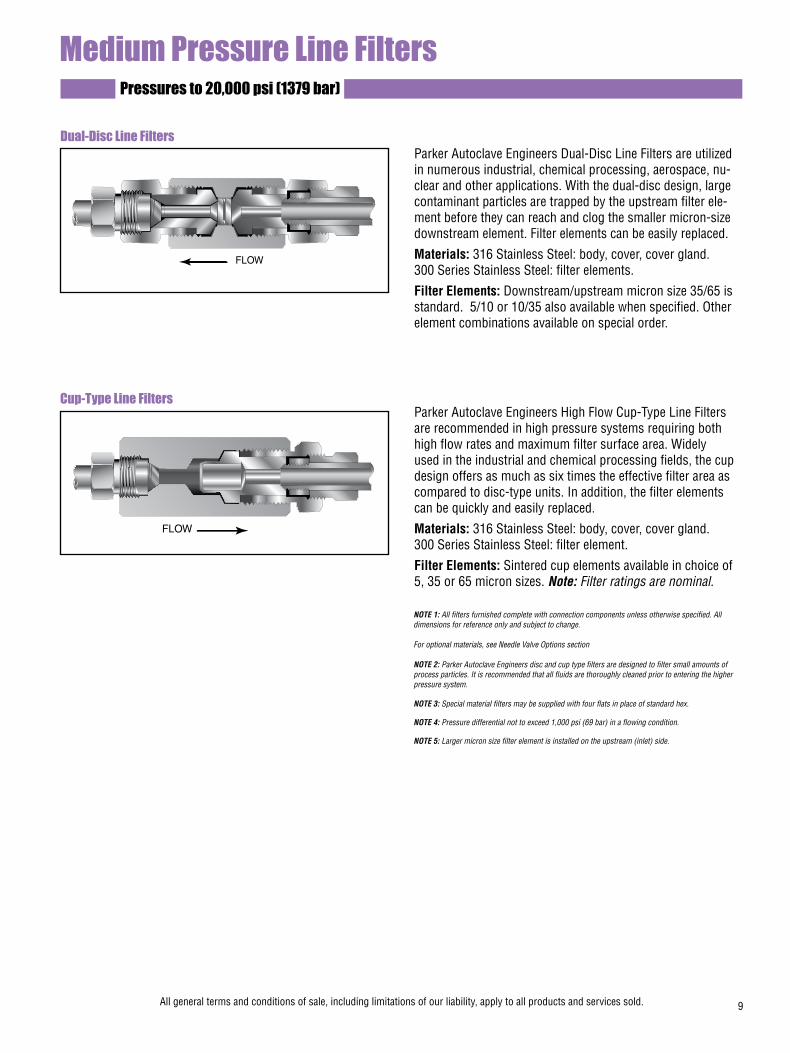
Medium Pressure Line FiltersPressures to 20,000 psi (1379 bar)
Parker Autoclave Engineers Dual-Disc Line Filters are utilized in numerous industrial, chemical processing, aerospace, nu-clear and other applications. With the dual-disc design, large contaminant particles are trapped by the upstream filter ele-ment before they can reach and clog the smaller micron-size downstream element. Filter elements can be easily replaced.
Materials: 316 Stainless Steel: body, cover, cover gland.300 Series Stainless Steel: filter elements.
Filter Elements: Downstream/upstream micron size 35/65 is standard. 5/10 or 10/35 also available when specified. Other element combinations available on special order.
Parker Autoclave Engineers High Flow Cup-Type Line Filters are recommended in high pressure systems requiring both high flow rates and maximum filter surface area. Widely used in the industrial and chemical processing fields, the cup design offers as much as six times the effective filter area as compared to disc-type units. In addition, the filter elements can be quickly and easily replaced.
Materials: 316 Stainless Steel: body, cover, cover gland.300 Series Stainless Steel: filter element.
Filter Elements: Sintered cup elements available in choice of 5, 35 or 65 micron sizes. Note: Filter ratings are nominal.
Dual-Disc Line Filters
Cup-Type Line Filters
NOTE 1: All filters furnished complete with connection components unless otherwise specified. All dimensions for reference only and subject to change.
For optional materials, see Needle Valve Options section
NOTE 2: Parker Autoclave Engineers disc and cup type filters are designed to filter small amounts of process particles. It is recommended that all fluids are thoroughly cleaned prior to entering the higher pressure system.
NOTE 3: Special material filters may be supplied with four flats in place of standard hex.
NOTE 4: Pressure differential not to exceed 1,000 psi (69 bar) in a flowing condition.
NOTE 5: Larger micron size filter element is installed on the upstream (inlet) side.
FLOW
FLOW
All general terms and conditions of sale, including limitations of our liability, apply to all products and services sold. 9
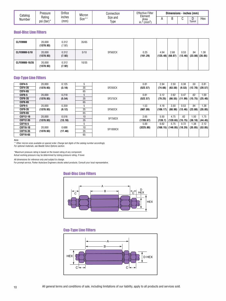
Cup-Type Line Filters
Note: **Other micron sizes available on special order. Change last digits of the catalog number accordingly.For optional materials, see Needle Valve Options section.
*Maximum pressure rating is based on the lowest rating of any component. Actual working pressure may be determined by tubing pressure rating, if lower.
All dimensions for reference only and subject to change.For prompt service, Parker Autoclave Engineers stocks select products. Consult your local representative.
Dimensions - inches (mm)Catalog Number
Orifice inches (mm)
Pressure Rating
psi (bar)*
Micron Size** A B C D Hex
Typical
Effective Filter
ElementArea
in.2 (mm2)
Connection Size and
Type
Dual-Disc Line Filters
CLFX9900 20,000 0.312 35/65 (1378.93) (7.92)
CLFX9900-5/10 20,000 0.312 5/10 SF562CX 0.25 4.94 2.68 0.53 .94 1.38 (1378.93) (7.92) (161.29) (125.48) (68.07) (13.46) (23.88) (35.05)
CLFX9900-10/35 20,000 0.312 10/35 (1378.93) (7.92)
10 All general terms and conditions of sale, including limitations of our liability, apply to all products and services sold.
Dual-Disc Line Filters
Cup-Type Line Filters
HEX
CB
AD
HEXC
HEX
C
B
A
C
D HEX
CXF4-5 20,000 0.125 5 0.81 2.94 2.50 0.38 .50 0.81 CXF4-35 (1378.93) (3.18) 35 SF250CX (522.57) (74.68) (63.50) (9.53) (12.70) (20.57) CXF4-65 65 CXF6-5 20,000 0.218 5 0.81 3.12 2.62 0.47 .62 1.00 CXF6-35 (1378.93) (5.54) 35 SF375CX (522.57) (79.25) (66.55) (11.99) (15.75) (25.40) CXF6-65 65 CXF9-5 20,000 0.359 5 1.53 4.18 3.50 0.53 .94 1.38 CXF9-35 (1378.93) (9.12) 35 SF562CX (987.09) (106.17) (88.90) (13.46) (23.88) (35.05) CXF9-65 65 CXF12-10 20,000 0.516 10 2.65 5.50 4.75 .62 1.50 1.75 CXF12-35 (1378.93) (13.10) 35 (1709.67) (139.7) (120.65) (15.75) (38.10) (44.45) CXF16-5 5 5.00 6.62 5.75 0.72 1.38 2.12 CXF16-10 20,000 0.688 10 (3225.80) (168.15) (146.05) (18.29) (35.05) (53.05) CXF16-35 (1378.93) (17.48) 35 CXF16-65 65
SF750CX
SF1000CX

Anti-Vibration Collet Gland AssemblyPressures to 20,000 psi (1379 bar)
Series KCBGLX Sizes to 1-1/2” (38.10 mm)For extreme conditions of vibration and/or shock in tubing systems, such as an unsupported line near a compressor, coned-and-threaded connections are offered with the Parker Autoclave anti-vibration collet gland assembly. Completely interchangeable with standard Parker Autoclave Engineers medium pressure connections, the collet gland assembly provides equally effective pressure handling capability.
In standard connection systems, the bending stresses on the threaded area of the tubing imposed by excessive vibration or movement may cause premature fatigue failure of the tubing at the back of the thread. By moving the stress concentration back to the unthreaded part of the tubing and providing a wedge-type gripping action, the Parker Autocalve Engineers anti-vibration collet gland assembly strengthens the entire structure. With stress concentration reduced and overall stress level maintained well below the endurance limit of the material, the result is virtu-ally unlimited vibrational fatigue life.
A less complex and more economical design than other vibra-tion-resistant connections, the collet gland assembly utilizes the same coned-and-threaded features of Parker Autoclave Engineers medium pressure connections. Series KCBGLX extends the gland nut to provide room for the tapered slotted collet. The design provides a slight difference in angles between the collet and the corresponding taper of the gland nut. As the nut is tightened, it acts to wedge the tapered end of the collet into a gripping engagement with the tubing.
Series KCBGLXPressures to 20,000 (1379 bar)
Materials Type 316 stainless steel with bonded dry film (316 MC) moly lubricant. Note: 1) To order components with anti-vibration assemblies add -K to catalog numbers. 2) Special material assemblies may be supplied with four flats in place of standard hex.
CatalogNumber Part
Outside Diameter
Tubing Sizein. (mm)
Dimensions - inches (mm)
A B Hex
Series KCBGLX20,000 psi ( 1379 bar)
Standard Parker Autoclave Engineers collar not included
in complete assembly
AB
Hex
Gland Nut
Collet grips tubing here for anti-vibration support
Collar
Slotted Collet
Collet Body
Valve or fitting body
Line contact seating
All dimensions for reference only and subject to change.For prompt service, Parker Autoclave Engineers stocks select products. Consult your local representative.
All general terms and conditions of sale, including limitations of our liability, apply to all products and services sold. 11
KCBGLX40-316MC Complete assembly KCBLX40-316MC Collet body 1/4 0.94 1.19 0.62 KCCLX40-316MC Slotted collet (6.35) (23.88) (30.23) (15.75) KGLX40-316MC Gland nut KCBGLX60-316MC Complete assembly KCBLX60-316MC Collet body 3/8 1.19 1.50 0.81 KCCLX60-316MC Slotted collet (9.53) (30.23) (38.10) (20.63) KGLX60-316MC Gland nut KCBGLX90-316MC Complete assembly KCBLX90-316MC Collet body 9/16 1.41 1.78 0.94 KCCLX90-316MC Slotted collet (14.29) (35.81) (45.21) (23.88) KGLX90-316MC Gland nut KCBGLX120-316MC Complete assembly KCBLX120-316MC Collet body 3/4 1.59 2.00 1.25 KCCLX120-316MC Slotted collet (19.05) (40.37) (50.80) (31.75) KGLX120-316MC Gland nut KCBGLX160-316MC Complete assembly KCBLX160-316MC Collet body 1 1.69 2.38 1.50 KCCLX160-316MC Slotted collet (25.40) (42.93) (60.45) (38.10) KGLX160-316MC Gland nut KCBGLX240-316MC Complete assembly KCBLX240-316MC Collet body 1-1/2 2.75 3.63 2.25 KCCLX240-316MC Slotted collet (38.10) (69.85) (92.20) (57.15) KGLX240-316MC Gland nut

02-0124SE January2013© 2013 Parker Hannifin Corporation | Autoclave Engineers is a registered trademark of the Parker Hannifin Corporation
Parker Hannifin Manufacturing Ltd. Instrumentation Products Division, Europe Industrial Estate WhitemillWexford, Republic of IrelandPH: 353 53 914 1566FAX: 353 53 914 1582
Instrumentation Products DivisionAutoclave Engineers Operation8325 Hessinger DriveErie, Pennsylvania 16509-4679 USAPH: 814-860-5700 FAX: 814-860-5811www.autoclave.com
WARNING
FAILURE, IMPROPER SELECTION OR IMPROPER USE OF THE PRODUCTS AND/OR SYSTEMS DESCRIBED HEREIN OR RELATED ITEMS CAN CAUSE DEATH, PERSONAL INJURY AND PROPERTY DAMAGE.This document and other information from Parker Hannifin Corporation, its subsidiaries and authorized distributors provide product and/or system options for further investigation by users having technical expertise. It is important that you analyze all aspects of your application and review the information concerning the product or system in the current product catalog. Due to the variety of operating conditions and applications for these products or systems, the user, through its own analysis and testing, is solely responsible for making the final selection of the products and systems and assuring that all performance, safety and warning requirements of the application are met. The products described herein, including without limitation, product features, specifications, designs, availability and pricing, are subject to change by Parker Hannifin Corporation and its subsidiaries at any time without notice.
Offer of Sale
The items described in this document are available for sale by Parker Hannifin Corporation, its subsidiaries or its authorized distributors. Any sale contract entered by Parker will be governed by the provisions stated in Parker's standard terms and conditions of sale (copy available upon request).
ISO-9001 Certified
Caution! Do not mix or interchange parts or tubing with those of other manufacturers. Doing so is unsafe and will void warranty.
Caution! Parker Autoclave Engineers Valves, Fittings and Tools are not designed to work with common commercial instrument tubing and will only work with tubing built to Parker Autoclave Engineers AES Specifications. Failure to do so will void warranty.
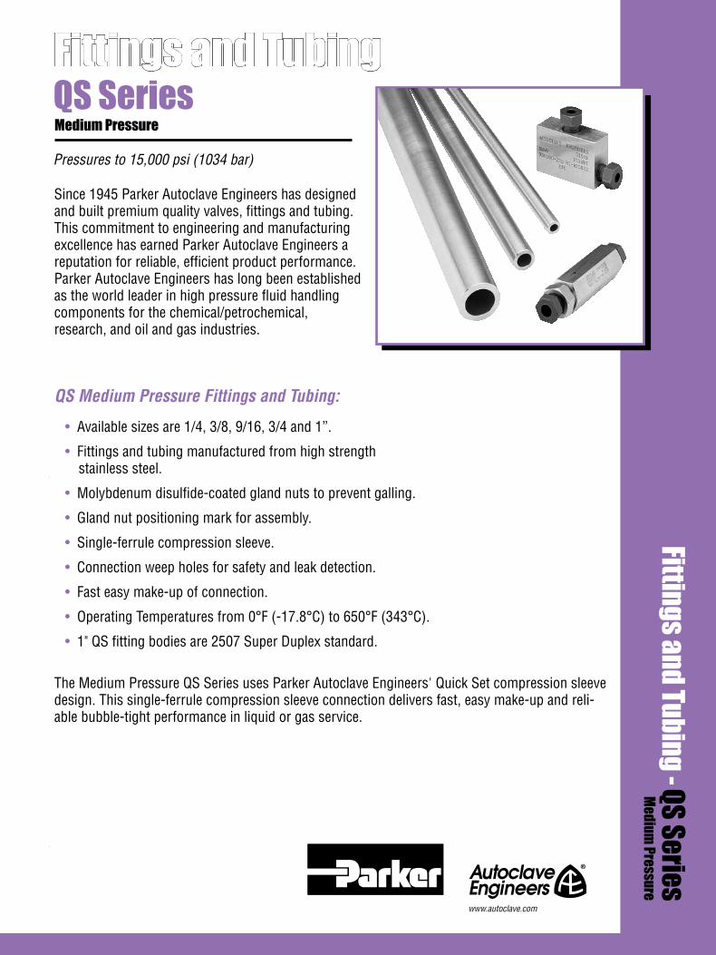
Pressures to 15,000 psi (1034 bar)
Fittings and TubingFittings and Tubing - QS Series
Medium Pressure
QS SeriesMedium Pressure
Since 1945 Parker Autoclave Engineers has designed and built premium quality valves, fittings and tubing. This commitment to engineering and manufacturing excellence has earned Parker Autoclave Engineers a reputation for reliable, efficient product performance. Parker Autoclave Engineers has long been established as the world leader in high pressure fluid handling components for the chemical/petrochemical, research, and oil and gas industries.
QS Medium Pressure Fittings and Tubing:
• Available sizes are 1/4, 3/8, 9/16, 3/4 and 1”.
• Fittings and tubing manufactured from high strength stainless steel.
• Molybdenum disulfide-coated gland nuts to prevent galling.
• Gland nut positioning mark for assembly.
• Single-ferrule compression sleeve.
• Connection weep holes for safety and leak detection.
• Fast easy make-up of connection.
• Operating Temperatures from 0°F (-17.8°C) to 650°F (343°C).
• 1" QS fitting bodies are 2507 Super Duplex standard.
The Medium Pressure QS Series uses Parker Autoclave Engineers' Quick Set compression sleeve design. This single-ferrule compression sleeve connection delivers fast, easy make-up and reli-able bubble-tight performance in liquid or gas service.
www.autoclave.com

2

Elbow
Dimensions - inches (mm)
See Figure 1
Connection ComponentsAll Parker Autoclave Engineers valves and fittings are supplied complete with appropriate glands and sleeves. To order these components separately, use order numbers listed. When using plug, sleeve is not required.
To ensure proper fit use Parker Autoclave Engineers tubing. For mounting hole option add suffix PM to catalog number. Consult factory for mounting hole dimensions.
Gland QSG ( )
Add tube size ( ) Example: 1/4” - 40 1/4” Gland - QSG 40 3/8” - 60 9/16” - 90 3/4” - 120 1" - 160
Catalog Number
Connection Type
Outside Diameter
Tube
Pressure Rating
psi (bar)*
Minimum Opening
Block Thickness
Fitting Pattern A B C D E F G
Typical Thickness
Elbow
Figure 1
D HEXF
C
A
B
E
Plug QSP ( )
Sleeve QSS ( )
*Maximum pressure rating is based on the lowest rating of any component. Actual working pressure may be determined by tubing pressure rating, if lower.
All dimensions for reference only and subject to change.For prompt service, Parker Autoclave Engineers stocks select products. Consult your local representative.
1" QS fitting bodies are 2507 Super Duplex
For mounting hole option add suffix PM to catalog number. Consult factory for mounting hole dimensions.
Fittings and Tubing - QS SeriesPressures to 15,000 psi (1034 bar)
Parker Autoclave Engineers Medium Pressure QS Fittings are designed for use with QS Series valves and medium pressure tub-ing. These fittings feature improved compression connections with larger orifices for excellent flow capabilities. Parker Autoclave Engineers fittings and components are manufactured of high strength stainless steel.
QSL4400 QS250 1/4 15,000 0.16 1.38 2.00 0.52 0.63 1.00 1.00 0.75 (6.35) (1034.20) (3.99) (34.93) (50.80) (13.23) (15.88) (25.40) (25.40) (19.05) QSL6600 QS375 3/8 15,000 0.25 1.50 2.00 0.55 0.75 1.00 1.00 0.81 (9.53) (1034.20) (6.35) (38.10) (50.80) (14.00) (19.05) (25.40) (25.40) (20.62) QSL9900 QS562 9/16 15,000 0.36 2.19 3.00 0.82 1.19 1.50 1.50 1.25 (14.29) (1034.20) (9.12) (55.58) (76.20) (20.83) (30.18) (38.10) (38.10) (31.75) QSL12 QS750 3/4 15,000 0.52 2.94 4.13 1.04 1.50 2.06 2.06 1.50 (19.05) (1034.20) (13.11) (74.63) (104.78) (26.37) (38.10) (52.40) (52.40) (38.10) QSL16 QSF1000 1 15,000 0.688 3.5 4.75 1.19 1.75 2.38 2.38 2.00 (25.4) (1034.20) (17.48) (88.90) (120.65) (30.18) (44.45) (60.33) (60.33) (50.80)
3
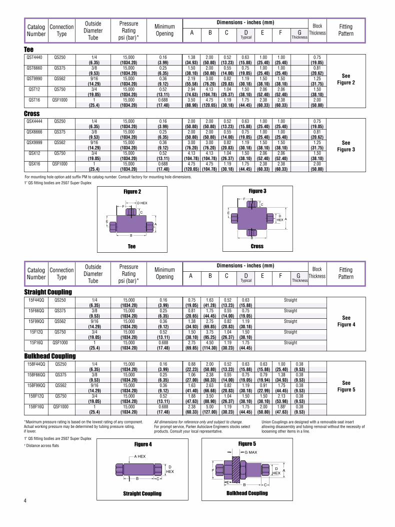
Dimensions - inches (mm)Catalog Number
Connection Type
Outside Diameter
Tube
Pressure Rating
psi (bar)*
Minimum Opening
Block Thickness
Fitting Pattern A B C D E F G
Typical Thickness
Tee
See Figure 2
Cross
See Figure 3
Cross
Figure 3
DHEX
F
C
A
B
E
Tee
Figure 2
D HEXF
C
A
B
E
*Maximum pressure rating is based on the lowest rating of any component. Actual working pressure may be determined by tubing pressure rating, if lower.
For mounting hole option add suffix PM to catalog number. Consult factory for mounting hole dimensions.
QST4440 QS250 1/4 15,000 0.16 1.38 2.00 0.52 0.63 1.00 1.00 0.75 (6.35) (1034.20) (3.99) (34.93) (50.80) (13.23) (15.88) (25.40) (25.40) (19.05) QST6660 QS375 3/8 15,000 0.25 1.50 2.00 0.55 0.75 1.00 1.00 0.81 (9.53) (1034.20) (6.35) (38.10) (50.80) (14.00) (19.05) (25.40) (25.40) (20.62) QST9990 QS562 9/16 15,000 0.36 2.19 3.00 0.82 1.19 1.50 1.50 1.25 (14.29) (1034.20) (9.12) (55.58) (76.20) (20.83) (30.18) (38.10) (38.10) (31.75) QST12 QS750 3/4 15,000 0.52 2.94 4.13 1.04 1.50 2.06 2.06 1.50 (19.05) (1034.20) (13.11) (74.63) (104.78) (26.37) (38.10) (52.40) (52.40) (38.10) QST16 QSF1000 1 15,000 0.688 3.50 4.75 1.19 1.75 2.38 2.38 2.00 (25.4) (1034.20) (17.48) (88.90) (120.65) (30.18) (44.45) (60.33) (60.33) (50.80)
Straight Coupling 15F44QQ QS250 1/4 15,000 0.16 0.75 1.63 0.52 0.63 Straight (6.35) (1034.20) (3.99) (19.05) (41.28) (13.23) (15.88) 15F66QQ QS375 3/8 15,000 0.25 0.81 1.75 0.55 0.75 Straight (9.53) (1034.20) (6.35) (20.65) (44.45) (14.00) (19.05) 15F99QQ QS562 9/16 15,000 0.36 1.38 2.75 0.82 1.19 Straight (14.29) (1034.20) (9.12) (34.93) (69.85) (20.83) (30.18) 15F12Q QS750 3/4 15,000 0.52 1.50 3.75 1.04 1.50 Straight (19.05) (1034.20) (13.11) (38.10) (95.25) (26.37) (38.10) 15F16Q QSF1000 1 15,000 0.688 2.75 4.50 1.19 1.75 Straight (25.4) (1034.20) (17.48) (69.85) (114.30) (30.23) (44.45)
See Figure 4
Bulkhead Coupling 15BF44QQ QS250 1/4 15,000 0.16 0.88 2.00 0.52 0.63 0.63 1.00 0.38 (6.35) (1034.20) (3.99) (22.23) (50.80) (13.23) (15.88) (15.88) (25.40) (9.53) 15BF66QQ QS375 3/8 15,000 0.25 1.06 2.38 0.55 0.75 0.79 1.38 0.38 (9.53) (1034.20) (6.35) (27.00) (60.33) (14.00) (19.05) (19.94) (34.93) (9.53) 15BF99QQ QS562 9/16 15,000 0.36 1.63 2.63 0.82 1.19 0.91 1.75 0.38 (14.29) (1034.20) (9.12) (41.40) (66.68) (20.83) (30.18) (22.99) (44.45) (9.53) 15BF12Q QS750 3/4 15,000 0.52 1.88 3.50 1.04 1.50 1.50 2.13 0.38 (19.05) (1034.20) (13.11) (47.63) (88.90) (26.37) (38.10) (38.10) (53.98) (9.53) 15BF16Q QSF1000 1 15,000 0.688 2.38 5.00 1.19 1.75 2.00 1.88† 0.38 (25.4) (1034.20) (17.48) (60.33) (127.00) (30.23) (44.45) (50.80) (47.63) (9.53)
See Figure 5
Straight Coupling
Figure 4
Bulkhead Coupling
Figure 5
DHEX
CB
A HEXG MAX
CB
F
E
ADHEX
Union Couplings are designed with a removable seat insert allowing disassembly and tubing removal without the necessity of loosening other items in a line.
All dimensions for reference only and subject to change.For prompt service, Parker Autoclave Engineers stocks select products. Consult your local representative.
QSX4444 QS250 1/4 15,000 0.16 2.00 2.00 0.52 0.63 1.00 1.00 0.75 (6.35) (1034.20) (3.99) (50.80) (50.80) (13.23) (15.88) (25.40) (25.40) (19.05) QSX6666 QS375 3/8 15,000 0.25 2.00 2.00 0.55 0.75 1.00 1.00 0.81 (9.53) (1034.20) (6.35) (50.80) (50.80) (14.00) (19.05) (25.40) (25.40) (20.62) QSX9999 QS562 9/16 15,000 0.36 3.00 3.00 0.82 1.19 1.50 1.50 1.25 (14.29) (1034.20) (9.12) (76.20) (76.20) (20.83) (30.18) (38.10) (38.10) (31.75) QSX12 QS750 3/4 15,000 0.52 4.13 4.13 1.04 1.50 2.06 2.06 1.50 (19.05) (1034.20) (13.11) (104.78) (104.78) (26.37) (38.10) (52.40) (52.40) (38.10) QSX16 QSF1000 1 15,000 0.688 4.75 4.75 1.19 1.75 2.38 2.38 2.00 (25.4) (1034.20) (17.48) (120.65) (104.78) (30.18) (44.45) (60.33) (60.33) (50.80)
4
Dimensions - inches (mm)Catalog Number
Connection Type
Outside Diameter
Tube
Pressure Rating
psi (bar)*
Minimum Opening
Block Thickness
Fitting Pattern A B C D E F G
Typical Thickness
1" QS fitting bodies are 2507 Super Duplex
1" QS fitting bodies are 2507 Super Duplex† Distance across flats

Pressures to 15,000 psi (1034 bar)
Parker Autoclave Engineers offers a complete selection of austenetic, cold drawn stainless steel tubing designed to match the performance standards of Parker Autoclave Engineers valves and fittings. Parker Autoclave Engineers medium pres-sure tubing is manufactured specifically for high pressure applications requiring both strength and corrosion resistance. The tubing is furnished in random lengths between 20 feet (6 meters) and 26.5 feet (8.0 meters). The average is 24 feet (7.3 meters). Medium Pressure Tubing is available in five sizes and a variety of materials.
Inspection and TestingParker Autoclave Engineer’s medium pressure tubing is inspected to assure freedom from seams, laps, fissures or other flaws, as well as carburization or intergranular carbide precipitation. The outside and inside diameters of the tubing are subject to special inspection and are controlled within close tolerences to assure proper fit. Sample pieces of tube for each lot are tested to confirm mechanical properties. Hydrostatic testing is also performed on a statistical basis and is conducted at the working pressure of the tube. Parker Autoclave Engineers will perform 100% hydrostatic testing at additional cost if desired.
Medium Pressure Tubing
*Maximum pressure rating is based on the lowest rating of any component. Actual working pressure may be determined by tubing pressure rating, if lower.All dimensions for reference only and subject to change. For prompt service, Parker Autoclave Engineers stocks select products. Consult your local representative.**Larger inside diameters are available as special order.
Tubing ToleranceNominal Tubing Size Tolerance/Outside Diameterinches (mm) inches (mm)1/4 (6.35) .248/.243 (6.30/6.17)3/8 (9.53) .370/.365 (9.40/9.27)9/16 (14.27) .557/.552 (14.15/14.02)3/4 (19.05) .745/.740 (18.92/18.80)1 (25.4) .995/.990 (25.27/25.14)
MS15-092** 316SS 20,000 20,000 19,250 18,050 QS250 1/4 0.109 0.070 0.009 (1378.93) (1378.93) (1327.22) (1244.48) MS15-192** 304SS (6.35) (2.77) (1.78) (5.81) 20,000 18,950 17,200 17,000 (1378.93) (1306.54) (1185.88) (1172.09) MS15-093** 316SS 20,000 20,000 19,250 18,050 QS375 3/8 0.203 0.086 0.032 (1378.93) (1378.93) (1327.22) (1244.48) MS15-193** 304SS (9.53) (5.16) (2.18) (20.65) 20,000 20,000 19,250 18,050 (1378.93) (1378.93) (1327.22) (1244.48) MS15-097 316SS
Catalog Tube Fits Tube Size Inches (mm) Flow Working Pressure psi (bar)* Number Material Connection Outside Inside Wall Area -425 to 100°F 200°F 400°F 600°F Type Diameter Diameter Thickness in.2 (mm2) -252 to 37.8°C 93°C 204°C 316°C
QS562 9/16 0.359 0.101 0.101 (14.29) (9.12) (2.57) (65.16)
15,000 15,000 14,400 13,650(1034.19) (1034.19) (992.82) (941.12)
QS750 3/4 0.516 0.117 0.209 15,000 15,000 14,400 13,650 (19.05) (13.11) (2.97) (134.84) (1034.19) (1034.19) (992.82) (941.12)
5
MS15-194 304SS
MS15-099 316SS 0.688 0.156 0.371 15,000 15,000 14,400 13,650 (17.48) (3.96) (239.35) (1034.16) (1034.16) (992.83) (941.12)
QS1000 1(25.4)
Special MaterialsIn addition to the type 316/316L and 304/304L stainless steel tubing listed in this section, Parker Autoclave Engineers has limited stock of hard-to-obtain special tubing materials: Monel 400*, Inconel 600*, Inconel 625*, Duplex, SuperDuplex, Titanium Grade 2*, Nickel 200*, Hastelloy C276*(*Trademark names) Some are available in shorterlengths only. Please consult factory for stock availability.
MS15-098 316SS
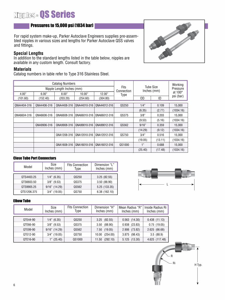
6
Pressures to 15,000 psi (1034 bar)
For rapid system make-up, Parker Autoclave Engineers supplies pre-assem-bled nipples in various sizes and lengths for Parker Autoclave QSS valves and fittings.
Special LengthsIn addition to the standard lengths listed in the table below, nipples areavailable in any custom length. Consult factory.
MaterialsCatalog numbers in table refer to Type 316 Stainless Steel.
Nipples - QS Series
Catalog NumbersNipple Length Inches (mm) Fits
ConnectionType
Tube SizeInches (mm)
Working Pressureat 100°psi (bar)
4.00” 6.00” 8.00” 10.00” 12.00” (101.60) (152.40) (203.20) (254.60) (304.80)
QNA4404-316 QNA4406-316 QNA4408-316 QNA44010-316 QNA44012-316 QS250 1/4” 0.109 15,000
(6.35) (2.77) (1034.16)
QNA6604-316 QNA6606-316 QNA6608-316 QNA66010-316 QNA66012-316 QS375 3/8” 0.203 15,000
(9.53) (5.16) (1034.16)
QNA9906-316 QNA9908-316 QNA99010-316 QNA99012-316 QS562 9/16” 0.359 15,000
(14.29) (9.12) (1034.16)
QNA1208-316 QNA12010-316 QNA12012-316 QS750 3/4” 0.516 15,000
(19.05) (13.11) (1034.16)
QNA1608-316 QNA16010-316 QNA16012-316 QS1000 1” 0.688 15,000
(25.40) (17.48) (1034.16)
Close Tube Port Connectors
ModelSize
Inches (mm)Fits Connection
TypeDimension “L”Inches (mm)
QTS4403.25 1/4” (6.35) QS250 3.25 (82.55)
QTS6603.50 3/8” (9.53) QS375 3.50 (88.90)
QTS9905.25 9/16” (14.29) QS562 5.25 (133.35)
QTS1206.375 3/4” (19.05) QS750 6.38 (162.10)
Elbow Tube
Model SizeInches (mm)
Fits ConnectionType
Dimension “H”Inches (mm)
QTE44-90 1/4” (6.35) QS250 3.25 (82.55) 0.563 (14.30) 0.438 (11.13)
QTE66-90 3/8” (9.53) QS375 3.50 (88.90) 0.938 (23.83) 0.75 (19.05)
QTE99-90 9/16” (14.29) QS562 7.50 (19.05) 2.906 (73.82) 2.625 (66.68)
QTE12-90 3/4” (19.05) QS750 10.00 (254.00) 3.875 (98.43) 3.5 (88.9)
QTE16-90 1” (25.40) QS1000 11.50 (292.10) 5.125 (13.30) 4.625 (117.48)
Mean Radius “R”Inches (mm)
Inside Radius RiInches (mm)
OD ID
L
H Typ.
R
Ri
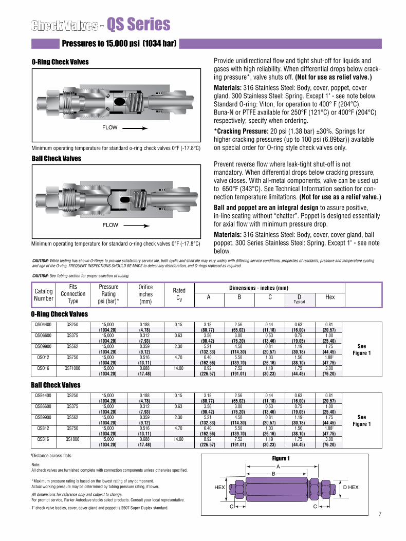
7
Check Valves - QS SeriesPressures to 15,000 psi (1034 bar)
Provide unidirectional flow and tight shut-off for liquids and gases with high reliability. When differential drops below crack-ing pressure*, valve shuts off. (Not for use as relief valve.)
Materials: 316 Stainless Steel: Body, cover, poppet, cover gland. 300 Stainless Steel: Spring. Except 1" - see note below.Standard O-ring: Viton, for operation to 400° F (204°C). Buna-N or PTFE available for 250°F (121°C) or 400°F (204°C) respectively; specify when ordering.
*Cracking Pressure: 20 psi (1.38 bar) ±30%. Springs for higher cracking pressures (up to 100 psi (6.89bar)) available on special order for O-ring style check valves only.
Prevent reverse flow where leak-tight shut-off is not mandatory. When differential drops below cracking pressure, valve closes. With all-metal components, valve can be used up to 650°F (343°C). See Technical Information section for con-nection temperature limitations. (Not for use as a relief valve.)
Ball and poppet are an integral design to assure positive, in-line seating without “chatter”. Poppet is designed essentially for axial flow with minimum pressure drop.
Materials: 316 Stainless Steel: Body, cover, cover gland, ball poppet. 300 Series Stainless Steel: Spring. Except 1" - see note below.
O-Ring Check Valves
Ball Check Valves
CAUTION: While testing has shown O-Rings to provide satisfactory service life, both cyclic and shelf life may vary widely with differing service conditions, properties of reactants, pressure and temperature cycling and age of the O-ring. FREQUENT INSPECTIONS SHOULD BE MADE to detect any deterioration, and O-rings replaced as required.
CAUTION: See Tubing section for proper selection of tubing.
FLOW
O-Ring Check Valves
Dimensions - inches (mm)
See Figure 1
Catalog Number
Fits Connection
Type
Orifice inches (mm)
Pressure Rating
psi (bar)*
Rated Cv A B C D Hex
Typical
Ball Check Valves
See Figure 1
Figure 1Note: All check valves are furnished complete with connection components unless otherwise specified.
*Maximum pressure rating is based on the lowest rating of any component. Actual working pressure may be determined by tubing pressure rating, if lower.
All dimensions for reference only and subject to change.For prompt service, Parker Autoclave stocks select products. Consult your local representative.
1" check valve bodies, cover, cover gland and poppet is 2507 Super Duplex standard.
†Distance across flats
HEX
C
B
A
C
D HEX
QSO4400 QS250 15,000 0.188 0.15 3.18 2.56 0.44 0.63 0.81 (1034.20) (4.78) (80.77) (65.02) (11.18) (16.00) (20.57) QSO6600 QS375 15,000 0.312 0.63 3.56 3.00 0.53 0.75 1.00 (1034.20) (7.93) (90.42) (76.20) (13.46) (19.05) (25.40) QSO9900 QS562 15,000 0.359 2.30 5.21 4.50 0.81 1.19 1.75 (1034.20) (9.12) (132.33) (114.30) (20.57) (30.18) (44.45) QSO12 QS750 15,000 0.516 4.70 6.40 5.50 1.03 1.50 1.88†
(1034.20) (13.11) (162.56) (139.70) (26.16) (38.10) (47.75) QSO16 QSF1000 15,000 0.688 14.00 8.92 7.52 1.19 1.75 3.00 (1034.20) (17.48) (226.57) (191.01) (30.23) (44.45) (76.20)
QSB4400 QS250 15,000 0.188 0.15 3.18 2.56 0.44 0.63 0.81 (1034.20) (4.78) (80.77) (65.02) (11.18) (16.00) (20.57) QSB6600 QS375 15,000 0.312 0.63 3.56 3.00 0.53 0.75 1.00 (1034.20) (7.93) (90.42) (76.20) (13.46) (19.05) (25.40) QSB9900 QS562 15,000 0.359 2.30 5.21 4.50 0.81 1.19 1.75 (1034.20) (9.12) (132.33) (114.30) (20.57) (30.18) (44.45) QSB12 QS750 15,000 0.516 4.70 6.40 5.50 1.03 1.50 1.88†
(1034.20) (13.11) (162.56) (139.70) (26.16) (38.10) (47.75) QSB16 QS1000 15,000 0.688 14.00 8.92 7.52 1.19 1.75 3.00 (1034.20) (17.48) (226.57) (191.01) (30.23) (44.45) (76.20)
FLOW
Minimum operating temperature for standard o-ring check valves 0°F (-17.8°C)
Minimum operating temperature for standard o-ring check valves 0°F (-17.8°C)
02-1247BE January2013© 2013 Parker Hannifin Corporation | Autoclave Engineers is a registered trademark of the Parker Hannifin Corporation
Parker Hannifin Manufacturing Ltd. Instrumentation Products Division, Europe Industrial Estate WhitemillWexford, Republic of IrelandPH: 353 53 914 1566FAX: 353 53 914 1582
Instrumentation Products DivisionAutoclave Engineers Operation8325 Hessinger DriveErie, Pennsylvania 16509-4679 USAPH: 814-860-5700 FAX: 814-860-5811www.autoclave.com
WARNING
FAILURE, IMPROPER SELECTION OR IMPROPER USE OF THE PRODUCTS AND/OR SYSTEMS DESCRIBED HEREIN OR RELATED ITEMS CAN CAUSE DEATH, PERSONAL INJURY AND PROPERTY DAMAGE.This document and other information from Parker Hannifin Corporation, its subsidiaries and authorized distributors provide product and/or system options for further investigation by users having technical expertise. It is important that you analyze all aspects of your application and review the information concerning the product or system in the current product catalog. Due to the variety of operating conditions and applications for these products or systems, the user, through its own analysis and testing, is solely responsible for making the final selection of the products and systems and assuring that all performance, safety and warning requirements of the application are met. The products described herein, including without limitation, product features, specifications, designs, availability and pricing, are subject to change by Parker Hannifin Corporation and its subsidiaries at any time without notice.
Offer of Sale
The items described in this document are available for sale by Parker Hannifin Corporation, its subsidiaries or its authorized distributors. Any sale contract entered by Parker will be governed by the provisions stated in Parker's standard terms and conditions of sale (copy available upon request).
ISO-9001 Certified
Caution! Do not mix or interchange parts or tubing with those of other manufacturers. Doing so is unsafe and will void warranty.
Caution! Parker Autoclave Engineers Valves, Fittings and Tools are not designed to work with common commercial instrument tubing and will only work with tubing built to Parker Autoclave Engineers AES Specifications. Failure to do so will void warranty.
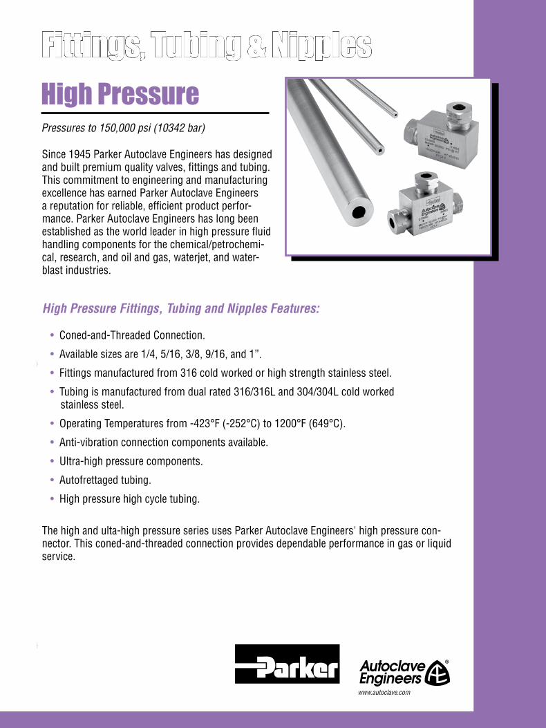
Since 1945 Parker Autoclave Engineers has designed and built premium quality valves, fittings and tubing. This commitment to engineering and manufacturing excellence has earned Parker Autoclave Engineers a reputation for reliable, efficient product perfor-mance. Parker Autoclave Engineers has long been established as the world leader in high pressure fluid handling components for the chemical/petrochemi-cal, research, and oil and gas, waterjet, and water-blast industries.
High Pressure Fittings, Tubing and Nipples Features:
• Coned-and-Threaded Connection.
• Available sizes are 1/4, 5/16, 3/8, 9/16, and 1”.
• Fittings manufactured from 316 cold worked or high strength stainless steel.
• Tubing is manufactured from dual rated 316/316L and 304/304L cold worked stainless steel.
• Operating Temperatures from -423°F (-252°C) to 1200°F (649°C).
• Anti-vibration connection components available.
• Ultra-high pressure components.
• Autofrettaged tubing.
• High pressure high cycle tubing.
The high and ulta-high pressure series uses Parker Autoclave Engineers' high pressure con-nector. This coned-and-threaded connection provides dependable performance in gas or liquid service.
Pressures to 150,000 psi (10342 bar)
High PressureFittings, Tubing & Nipples
www.autoclave.com
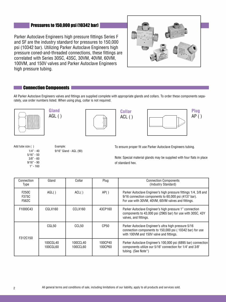
Pressures to 150,000 psi (10342 bar)
Parker Autoclave Engineers high pressure fittings Series F and SF are the industry standard for pressures to 150,000 psi (10342 bar). Utilizing Parker Autoclave Engineers high pressure coned-and-threaded connections, these fittings are correlated with Series 30SC, 43SC, 30VM, 40VM, 60VM, 100VM, and 150V valves and Parker Autoclave Engineers high pressure tubing.
To ensure proper fit use Parker Autoclave Engineers tubing.
Note: Special material glands may be supplied with four flats in place
of standard hex.
Gland AGL ( )
Add tube size ( ) Example: 1/4” - 40 9/16” Gland - AGL (90) 5/16” - 50 3/8” - 60 9/16” - 90 1” - 160
Plug AP ( )
Collar ACL ( )
Connection Gland Collar Plug Connection Components Type (Industry Standard)
F250C AGL( ) ACL( ) AP( ) Parker Autoclave Engineer’s high pressure fittings 1/4, 3/8 and F375C 9/16 connection components to 60,000 psi (4137 bar). F562C For use with 30VM, 40VM, 60VM valves and fittings.
F1000C43 CGLX160 CCLX160 43CP160 Parker Autoclave Engineer’s high pressure 1” connection components to 43,000 psi (2965 bar) for use with 30SC, 43Y valves, and fittings.
CGL50 CCL50 CP50 Parker Autoclave Engineer’s ultra high pressure 5/16 connection components to 150,000 psi ( 10342 bar) for use with 100VM and 150V valve and fittings. 100CGL40 100CCL40 100CP40 Parker Autoclave Engineer’s 100,000 psi (6895 bar) connection 100CGL60 100CCL60 100CP60 components utilize our 5/16" connection for 1/4" and 3/8" tubing. (See Note*)
All Parker Autoclave Engineers valves and fittings are supplied complete with appropriate glands and collars. To order these components sepa-rately, use order numbers listed. When using plug, collar is not required.
2 All general terms and conditions of sale, including limitations of our liability, apply to all products and services sold.
F312C150
Connection Components
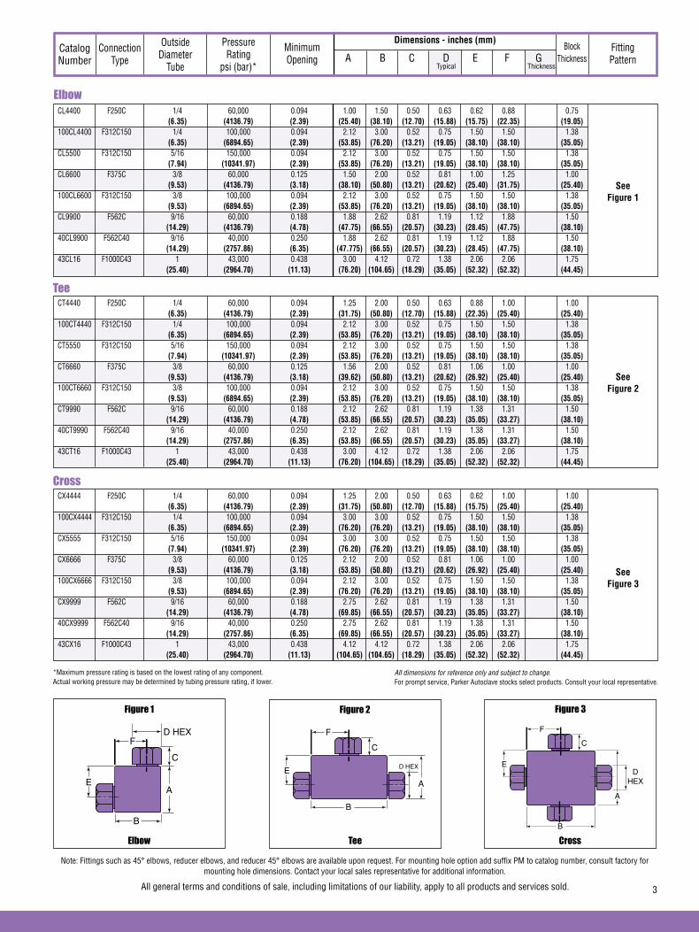
See Figure 1
Dimensions - inches (mm)Catalog Number
Connection Type
Outside Diameter
Tube
Pressure Rating
psi (bar)*
Minimum Opening
Block Thickness
Fitting Pattern A B C D E F G
Typical Thickness
Tee
See Figure 2
Cross
See Figure 3
Elbow
Figure 1
Tee
Figure 2
Cross
Figure 3
DHEX
F
C
A
B
E
Note: Fittings such as 45° elbows, reducer elbows, and reducer 45° elbows are available upon request. For mounting hole option add suffix PM to catalog number, consult factory for mounting hole dimensions. Contact your local sales representative for additional information.
D HEXF
C
A
B
E
D HEX
F
C
A
B
E
*Maximum pressure rating is based on the lowest rating of any component. Actual working pressure may be determined by tubing pressure rating, if lower.
All general terms and conditions of sale, including limitations of our liability, apply to all products and services sold. 3
All dimensions for reference only and subject to change.For prompt service, Parker Autoclave stocks select products. Consult your local representative.
CL4400 F250C 1/4 60,000 0.094 1.00 1.50 0.50 0.63 0.62 0.88 0.75 (6.35) (4136.79) (2.39) (25.40) (38.10) (12.70) (15.88) (15.75) (22.35) (19.05) 100CL4400 F312C150 1/4 100,000 0.094 2.12 3.00 0.52 0.75 1.50 1.50 1.38 (6.35) (6894.65) (2.39) (53.85) (76.20) (13.21) (19.05) (38.10) (38.10) (35.05) CL5500 F312C150 5/16 150,000 0.094 2.12 3.00 0.52 0.75 1.50 1.50 1.38 (7.94) (10341.97) (2.39) (53.85) (76.20) (13.21) (19.05) (38.10) (38.10) (35.05) CL6600 F375C 3/8 60,000 0.125 1.50 2.00 0.52 0.81 1.00 1.25 1.00 (9.53) (4136.79) (3.18) (38.10) (50.80) (13.21) (20.62) (25.40) (31.75) (25.40) 100CL6600 F312C150 3/8 100,000 0.094 2.12 3.00 0.52 0.75 1.50 1.50 1.38 (9.53) (6894.65) (2.39) (53.85) (76.20) (13.21) (19.05) (38.10) (38.10) (35.05) CL9900 F562C 9/16 60,000 0.188 1.88 2.62 0.81 1.19 1.12 1.88 1.50 (14.29) (4136.79) (4.78) (47.75) (66.55) (20.57) (30.23) (28.45) (47.75) (38.10) 40CL9900 F562C40 9/16 40,000 0.250 1.88 2.62 0.81 1.19 1.12 1.88 1.50 (14.29) (2757.86) (6.35) (47.775) (66.55) (20.57) (30.23) (28.45) (47.75) (38.10) 43CL16 F1000C43 1 43,000 0.438 3.00 4.12 0.72 1.38 2.06 2.06 1.75 (25.40) (2964.70) (11.13) (76.20) (104.65) (18.29) (35.05) (52.32) (52.32) (44.45)
CT4440 F250C 1/4 60,000 0.094 1.25 2.00 0.50 0.63 0.88 1.00 1.00 (6.35) (4136.79) (2.39) (31.75) (50.80) (12.70) (15.88) (22.35) (25.40) (25.40) 100CT4440 F312C150 1/4 100,000 0.094 2.12 3.00 0.52 0.75 1.50 1.50 1.38 (6.35) (6894.65) (2.39) (53.85) (76.20) (13.21) (19.05) (38.10) (38.10) (35.05) CT5550 F312C150 5/16 150,000 0.094 2.12 3.00 0.52 0.75 1.50 1.50 1.38 (7.94) (10341.97) (2.39) (53.85) (76.20) (13.21) (19.05) (38.10) (38.10) (35.05) CT6660 F375C 3/8 60,000 0.125 1.56 2.00 0.52 0.81 1.06 1.00 1.00 (9.53) (4136.79) (3.18) (39.62) (50.80) (13.21) (20.62) (26.92) (25.40) (25.40) 100CT6660 F312C150 3/8 100,000 0.094 2.12 3.00 0.52 0.75 1.50 1.50 1.38 (9.53) (6894.65) (2.39) (53.85) (76.20) (13.21) (19.05) (38.10) (38.10) (35.05) CT9990 F562C 9/16 60,000 0.188 2.12 2.62 0.81 1.19 1.38 1.31 1.50 (14.29) (4136.79) (4.78) (53.85) (66.55) (20.57) (30.23) (35.05) (33.27) (38.10) 40CT9990 F562C40 9/16 40,000 0.250 2.12 2.62 0.81 1.19 1.38 1.31 1.50 (14.29) (2757.86) (6.35) (53.85) (66.55) (20.57) (30.23) (35.05) (33.27) (38.10) 43CT16 F1000C43 1 43,000 0.438 3.00 4.12 0.72 1.38 2.06 2.06 1.75 (25.40) (2964.70) (11.13) (76.20) (104.65) (18.29) (35.05) (52.32) (52.32) (44.45)
CX4444 F250C 1/4 60,000 0.094 1.25 2.00 0.50 0.63 0.62 1.00 1.00 (6.35) (4136.79) (2.39) (31.75) (50.80) (12.70) (15.88) (15.75) (25.40) (25.40) 100CX4444 F312C150 1/4 100,000 0.094 3.00 3.00 0.52 0.75 1.50 1.50 1.38 (6.35) (6894.65) (2.39) (76.20) (76.20) (13.21) (19.05) (38.10) (38.10) (35.05) CX5555 F312C150 5/16 150,000 0.094 3.00 3.00 0.52 0.75 1.50 1.50 1.38 (7.94) (10341.97) (2.39) (76.20) (76.20) (13.21) (19.05) (38.10) (38.10) (35.05) CX6666 F375C 3/8 60,000 0.125 2.12 2.00 0.52 0.81 1.06 1.00 1.00 (9.53) (4136.79) (3.18) (53.85) (50.80) (13.21) (20.62) (26.92) (25.40) (25.40) 100CX6666 F312C150 3/8 100,000 0.094 2.12 3.00 0.52 0.75 1.50 1.50 1.38 (9.53) (6894.65) (2.39) (76.20) (76.20) (13.21) (19.05) (38.10) (38.10) (35.05) CX9999 F562C 9/16 60,000 0.188 2.75 2.62 0.81 1.19 1.38 1.31 1.50 (14.29) (4136.79) (4.78) (69.85) (66.55) (20.57) (30.23) (35.05) (33.27) (38.10) 40CX9999 F562C40 9/16 40,000 0.250 2.75 2.62 0.81 1.19 1.38 1.31 1.50 (14.29) (2757.86) (6.35) (69.85) (66.55) (20.57) (30.23) (35.05) (33.27) (38.10) 43CX16 F1000C43 1 43,000 0.438 4.12 4.12 0.72 1.38 2.06 2.06 1.75 (25.40) (2964.70) (11.13) (104.65) (104.65) (18.29) (35.05) (52.32) (52.32) (44.45)
Elbow
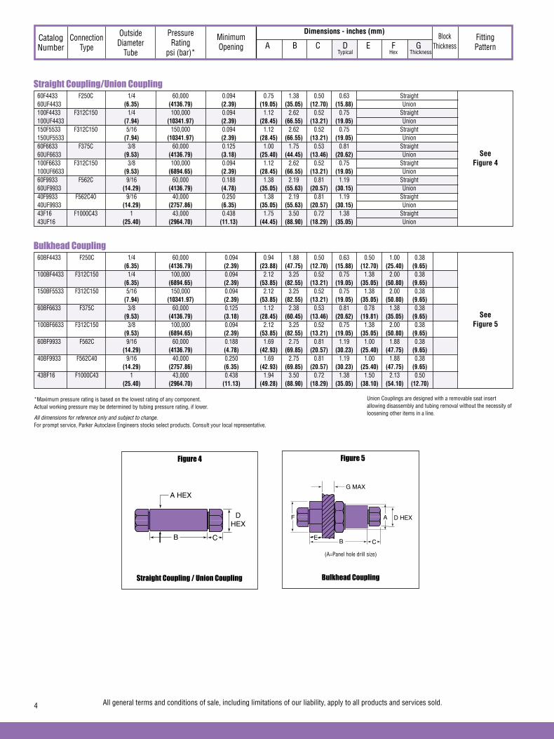
Straight Coupling/Union Coupling
See Figure 4
Dimensions - inches (mm)Catalog Number
Connection Type
Outside Diameter
Tube
Pressure Rating
psi (bar)*
Minimum Opening
Block Thickness
Fitting Pattern A B C D E F G
Typical Hex Thickness
Bulkhead Coupling
See Figure 5
Straight Coupling / Union Coupling
Figure 4
Bulkhead Coupling
Figure 5
DHEX
CB
A HEX
*Maximum pressure rating is based on the lowest rating of any component. Actual working pressure may be determined by tubing pressure rating, if lower.
All dimensions for reference only and subject to change.For prompt service, Parker Autoclave Engineers stocks select products. Consult your local representative.
All general terms and conditions of sale, including limitations of our liability, apply to all products and services sold.4
60F4433 F250C 1/4 60,000 0.094 0.75 1.38 0.50 0.63 Straight 60UF4433 (6.35) (4136.79) (2.39) (19.05) (35.05) (12.70) (15.88) Union 100F4433 F312C150 1/4 100,000 0.094 1.12 2.62 0.52 0.75 Straight 100UF4433 (7.94) (10341.97) (2.39) (28.45) (66.55) (13.21) (19.05) Union 150F5533 F312C150 5/16 150,000 0.094 1.12 2.62 0.52 0.75 Straight 150UF5533 (7.94) (10341.97) (2.39) (28.45) (66.55) (13.21) (19.05) Union 60F6633 F375C 3/8 60,000 0.125 1.00 1.75 0.53 0.81 Straight 60UF6633 (9.53) (4136.79) (3.18) (25.40) (44.45) (13.46) (20.62) Union 100F6633 F312C150 3/8 100,000 0.094 1.12 2.62 0.52 0.75 Straight 100UF6633 (9.53) (6894.65) (2.39) (28.45) (66.55) (13.21) (19.05) Union 60F9933 F562C 9/16 60,000 0.188 1.38 2.19 0.81 1.19 Straight 60UF9933 (14.29) (4136.79) (4.78) (35.05) (55.63) (20.57) (30.15) Union 40F9933 F562C40 9/16 40,000 0.250 1.38 2.19 0.81 1.19 Straight 40UF9933 (14.29) (2757.86) (6.35) (35.05) (55.63) (20.57) (30.15) Union 43F16 F1000C43 1 43,000 0.438 1.75 3.50 0.72 1.38 Straight 43UF16 (25.40) (2964.70) (11.13) (44.45) (88.90) (18.29) (35.05) Union
60BF4433 F250C 1/4 60,000 0.094 0.94 1.88 0.50 0.63 0.50 1.00 0.38 (6.35) (4136.79) (2.39) (23.88) (47.75) (12.70) (15.88) (12.70) (25.40) (9.65) 100BF4433 F312C150 1/4 100,000 0.094 2.12 3.25 0.52 0.75 1.38 2.00 0.38 (6.35) (6894.65) (2.39) (53.85) (82.55) (13.21) (19.05) (35.05) (50.80) (9.65) 150BF5533 F312C150 5/16 150,000 0.094 2.12 3.25 0.52 0.75 1.38 2.00 0.38 (7.94) (10341.97) (2.39) (53.85) (82.55) (13.21) (19.05) (35.05) (50.80) (9.65) 60BF6633 F375C 3/8 60,000 0.125 1.12 2.38 0.53 0.81 0.78 1.38 0.38 (9.53) (4136.79) (3.18) (28.45) (60.45) (13.46) (20.62) (19.81) (35.05) (9.65) 100BF6633 F312C150 3/8 100,000 0.094 2.12 3.25 0.52 0.75 1.38 2.00 0.38 (9.53) (6894.65) (2.39) (53.85) (82.55) (13.21) (19.05) (35.05) (50.80) (9.65) 60BF9933 F562C 9/16 60,000 0.188 1.69 2.75 0.81 1.19 1.00 1.88 0.38 (14.29) (4136.79) (4.78) (42.93) (69.85) (20.57) (30.23) (25.40) (47.75) (9.65) 40BF9933 F562C40 9/16 40,000 0.250 1.69 2.75 0.81 1.19 1.00 1.88 0.38 (14.29) (2757.86) (6.35) (42.93) (69.85) (20.57) (30.23) (25.40) (47.75) (9.65) 43BF16 F1000C43 1 43,000 0.438 1.94 3.50 0.72 1.38 1.50 2.13 0.50 (25.40) (2964.70) (11.13) (49.28) (88.90) (18.29) (35.05) (38.10) (54.10) (12.70)
G MAX
CB
F
E
A D HEX
(A=Panel hole drill size)
Union Couplings are designed with a removable seat insert allowing disassembly and tubing removal without the necessity of loosening other items in a line.
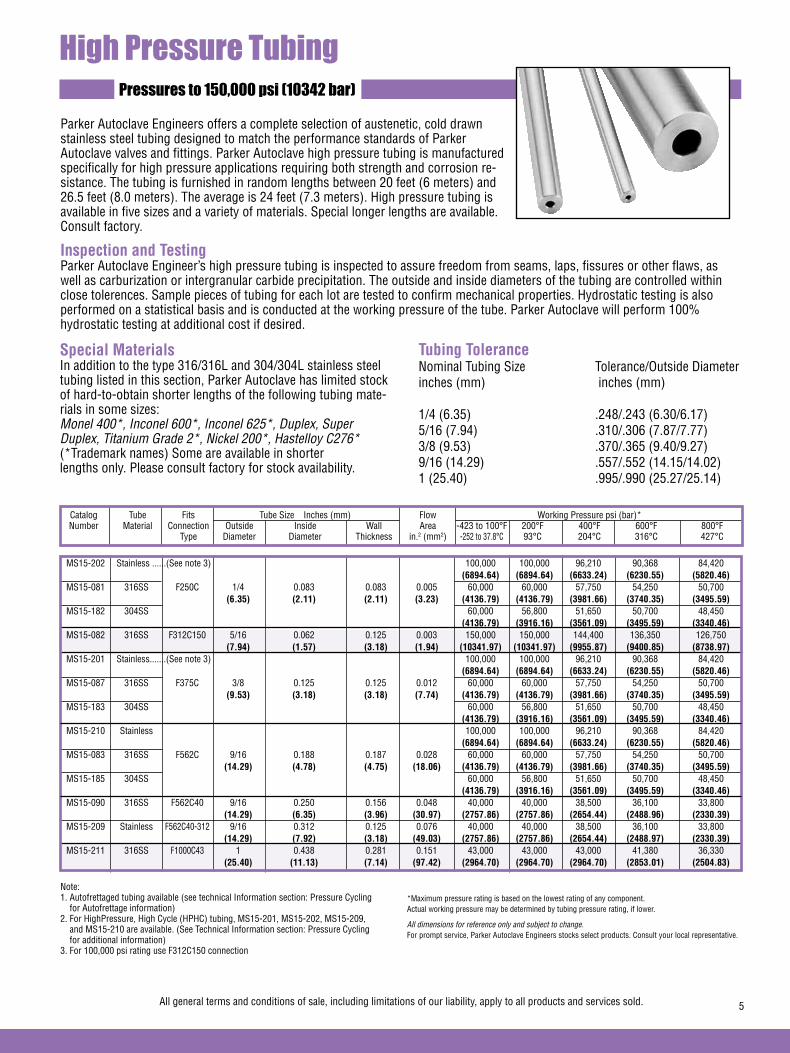
Pressures to 150,000 psi (10342 bar)
Parker Autoclave Engineers offers a complete selection of austenetic, cold drawn stainless steel tubing designed to match the performance standards of Parker Autoclave valves and fittings. Parker Autoclave high pressure tubing is manufactured specifically for high pressure applications requiring both strength and corrosion re-sistance. The tubing is furnished in random lengths between 20 feet (6 meters) and 26.5 feet (8.0 meters). The average is 24 feet (7.3 meters). High pressure tubing is available in five sizes and a variety of materials. Special longer lengths are available. Consult factory.
Catalog Tube Fits Tube Size Inches (mm) Flow Working Pressure psi (bar)* Number Material Connection Outside Inside Wall Area -423 to 100°F 200°F 400°F 600°F 800°F Type Diameter Diameter Thickness in.2 (mm2) -252 to 37.8°C 93°C 204°C 316°C 427°C
Special MaterialsIn addition to the type 316/316L and 304/304L stainless steel tubing listed in this section, Parker Autoclave has limited stock of hard-to-obtain shorter lengths of the following tubing mate-rials in some sizes:Monel 400*, Inconel 600*, Inconel 625*, Duplex, SuperDuplex, Titanium Grade 2*, Nickel 200*, Hastelloy C276*(*Trademark names) Some are available in shorterlengths only. Please consult factory for stock availability.
Tubing ToleranceNominal Tubing Size Tolerance/Outside Diameterinches (mm) inches (mm) 1/4 (6.35) .248/.243 (6.30/6.17)5/16 (7.94) .310/.306 (7.87/7.77)3/8 (9.53) .370/.365 (9.40/9.27)9/16 (14.29) .557/.552 (14.15/14.02)1 (25.40) .995/.990 (25.27/25.14)
High Pressure Tubing
Note: 1. Autofrettaged tubing available (see technical Information section: Pressure Cycling for Autofrettage information)2. For HighPressure, High Cycle (HPHC) tubing, MS15-201, MS15-202, MS15-209, and MS15-210 are available. (See Technical Information section: Pressure Cycling for additional information)3. For 100,000 psi rating use F312C150 connection
All general terms and conditions of sale, including limitations of our liability, apply to all products and services sold. 5
*Maximum pressure rating is based on the lowest rating of any component. Actual working pressure may be determined by tubing pressure rating, if lower.
All dimensions for reference only and subject to change.For prompt service, Parker Autoclave Engineers stocks select products. Consult your local representative.
Inspection and TestingParker Autoclave Engineer’s high pressure tubing is inspected to assure freedom from seams, laps, fissures or other flaws, as well as carburization or intergranular carbide precipitation. The outside and inside diameters of the tubing are controlled within close tolerences. Sample pieces of tubing for each lot are tested to confirm mechanical properties. Hydrostatic testing is also performed on a statistical basis and is conducted at the working pressure of the tube. Parker Autoclave will perform 100% hydrostatic testing at additional cost if desired.
MS15-202 Stainless ......(See note 3) 100,000 100,000 96,210 90,368 84,420 (6894.64) (6894.64) (6633.24) (6230.55) (5820.46) MS15-081 316SS F250C 1/4 0.083 0.083 0.005 60,000 60,000 57,750 54,250 50,700 (6.35) (2.11) (2.11) (3.23) (4136.79) (4136.79) (3981.66) (3740.35) (3495.59) MS15-182 304SS 60,000 56,800 51,650 50,700 48,450 (4136.79) (3916.16) (3561.09) (3495.59) (3340.46) MS15-082 316SS F312C150 5/16 0.062 0.125 0.003 150,000 150,000 144,400 136,350 126,750 (7.94) (1.57) (3.18) (1.94) (10341.97) (10341.97) (9955.87) (9400.85) (8738.97) MS15-201 Stainless.......(See note 3) 100,000 100,000 96,210 90,368 84,420 (6894.64) (6894.64) (6633.24) (6230.55) (5820.46) MS15-087 316SS F375C 3/8 0.125 0.125 0.012 60,000 60,000 57,750 54,250 50,700 (9.53) (3.18) (3.18) (7.74) (4136.79) (4136.79) (3981.66) (3740.35) (3495.59) MS15-183 304SS 60,000 56,800 51,650 50,700 48,450 (4136.79) (3916.16) (3561.09) (3495.59) (3340.46) MS15-210 Stainless 100,000 100,000 96,210 90,368 84,420 (6894.64) (6894.64) (6633.24) (6230.55) (5820.46) MS15-083 316SS F562C 9/16 0.188 0.187 0.028 60,000 60,000 57,750 54,250 50,700 (14.29) (4.78) (4.75) (18.06) (4136.79) (4136.79) (3981.66) (3740.35) (3495.59) MS15-185 304SS 60,000 56,800 51,650 50,700 48,450 (4136.79) (3916.16) (3561.09) (3495.59) (3340.46) MS15-090 316SS F562C40 9/16 0.250 0.156 0.048 40,000 40,000 38,500 36,100 33,800 (14.29) (6.35) (3.96) (30.97) (2757.86) (2757.86) (2654.44) (2488.96) (2330.39) MS15-209 Stainless F562C40-312 9/16 0.312 0.125 0.076 40,000 40,000 38,500 36,100 33,800 (14.29) (7.92) (3.18) (49.03) (2757.86) (2757.86) (2654.44) (2488.97) (2330.39) MS15-211 316SS F1000C43 1 0.438 0.281 0.151 43,000 43,000 43,000 41,380 36,330 (25.40) (11.13) (7.14) (97.42) (2964.70) (2964.70) (2964.70) (2853.01) (2504.83)

Pressures to 150,000 psi (10342 bar)
High Pressure Coned-and-Threaded Nipples
For rapid system make-up, Parker Autoclave Engineers supplies pre-cut, coned-and-threaded nipples in various sizes and lengths for Parker Autoclave high pressure valves and fittings.
Special lengthsIn addition to the standard lengths listed in the table below, nipples are available in any custom length. Consult factory.
Materials**Catalog numbers in table refer to Type 316 Stainless steel.Note: Most items available in 304SS. Consult factory for availability.
FitsConnection
Type
Working*Pressure
at 100°F (37.8°C)psi (bar)
Tube Size inches(mm)
Note: See High pressure tubing section for pressure ratings at various temperatures.
Material in table is 316 Stainless steel
*Maximum pressure rating is based on the lowest rating of any component. Actual working pressure may be determined by tubing pressure rating, if lower.
All dimensions for reference only and subject to change.For prompt service, Parker Autoclave Engineers stocks select products. Consult your local representative.
All general terms and conditions of sale, including limitations of our liability, apply to all products and services sold.6
Catalog Number Nipple Length In (mm)
2.75” 3.00” 4.00” 6.00” 8.00” 10.00” 12.00” (69.85) (76.20) (101.60) (152.40) (203.20) (254.00) (304.80) O.D. I.D.
CN4402-316 CN4403-316 CN4404-316 CN4406-316 CN4408-316 CN44010-316 CN44012-316 F250C 1/4 0.083 60,000 (6.35) (2.11) (4136.79)
CN5504-316 CN5506-316 CN5508-316 CN55010-316 CN55012-316 F312C150 5/16 0.062 150,000 (7.94) (1.57) (10341.97)
CN6603-316 CN6604-316 CN6606-316 CN6608-316 CN66010-316 CN66012-316 F375C 3/8 0.125 60,000 (9.53) (3.18) (4136.79)
CN9904-316 CN9906-316 CN9908-316 CN99010-316 CN99012-316 F562C 9/16 0.188 60,000 (14.29) (4.78) (4136.79)
40CN9904-316 40CN9906-316 40CN9908-316 40CN99010-316 40CN99012-316 F562C40 9/16 0.250 40,000 (14.29) (6.35) (2757.86)
43CN1606-316 43CN1608-316 43CN16010-316 43CN16012-316 F1000C43 1 0.438 43,000 (25.40) (12.40) (2964.70)

High Pressure Check ValvesPressures to 60,000 psi (4137 bar)
Provides unidirectional flow and tight shut-off for liquids and gas with high reliability. When differential drops below crack-ing pressure*, valve shuts off. (Not for use as relief valve.)
Materials: 316 Stainless Steel: body, cover, poppet, cover gland. 300 Series Stainless Steel: spring. Standard O-ring: Viton, for operation to 400° F (204°C). Buna-N or PTFE available for 250°F (121°C) or 400°F (204°C) respectively; specify when ordering.
*Cracking Pressure: 20 psi (1.38 bar) ±30%. Springs for higher cracking pressures (up to 100 psi (6.89 bar) available on special order for O-ring style check valves only.
Prevents reverse flow where leak-tight shut-off is not manda-tory. When differential drops below cracking pressure, valve closes. With all-metal components, valve can be used up to 1200°F (649°C). See Technical Information section for connection temperature limitations. (Not for use as a relief valve.)
Ball and poppet are an integral design to assure positive, in-line seating without “chatter”. Poppet is designed essentially for axial flow with minimum pressure drop.
Materials: 316 Stainless Steel: body, cover, ball poppet, cover gland. 300 Series Stainless Steel: spring.
Protects pressure gauges and pressure instrumentation from surges in flow or sudden venting in the event of line failure.
Materials: 316 Stainless Steel: body, cover, sleeve, cover gland. 300 Series Stainless Steel: ball.
Vertical Installation: Since this type of check valve employs a non-spring loaded ball, valve MUST be installed in VERTICAL position with arrow on valve body pointing UP. (cover gland up).
Resetting Valve: Equalize the pressure across the ball. The ball will drop and reset automatically.
O-Ring Check Valves
Ball Check Valves
Ball Type Excess Flow Valves
CAUTION: While testing has shown O-Rings to provide satisfactory service life, both cyclic and shelf life may vary widely with differing service conditions, properties of reactants, pressure and temperature cycling and age of the O-ring. FREQUENT INSPECTIONS SHOULD BE MADE to detect any deterioration, and O-rings replaced as required.
NOTE: For optional material see Needle Valve Options section.
FLO
W
(Vertical Installation O
nly)
7All general terms and conditions of sale, including limitations of our liability, apply to all products and services sold.
FLOW
Minimum operating temperature for standard o-ring check valves 0°F (-17.8°C).For low temperature option to -423°F (-252°C) add suffix LTTO (Low temperature spring & PTFE o-ring).
Minimum operating temperature for standard ball check valves -110°F (-79°C).For low temperature option to -423°F (-252°C) add suffix LT (Low temperature spring).
FLOW

O-Ring Check Valves CKO4400 F250C 60,000 0.094 0.15 3.38 2.50 0.50 0.63 1.18 (4136.79) (2.39) (85.85) (63.50) (12.70) (16.00) (29.97) CKO6600 F375C 60,000 0.125 0.28 3.75 2.62 0.53 0.75 1.18 (4136.79) (3.18) (95.25) (66.55) (13.46) (19.05) (29.97) CKO9900 F562C 60,000 0.187 0.63 4.62 3.38 0.81 1.12 1.50 (4136.79) (4.75) (117.35) (85.85) (20.57) (28.45) (38.10) 40CKO9900 F562C40 40,000 0.250 0.78 4.64 3.38 0.72 1.19 1.50 (2757.85) (6.35) (117.86) (85.73) (18.29) (30.23) (38.10) 43CKO16 F1000C43 43,000 0.438 4.3 6.54 5.63 .72 1.38 1.88†
(2964.70) (11.13) (166.11) (143.00) (18.29) (35.05) (47.76)
Dimensions - inches (mm)
High Pressure Check Valves
Catalog Number
Fits Connection
Type
Orifice inches (mm)
Pressure Rating
psi (bar)*
Rated Cv A B C D Hex
Typical
Ball Check Valves CB4401 F250C 60,000 0.094 0.15 3.38 2.50 0.50 0.63 1.18 (4136.79) (2.39) (85.85) (63.50) (12.70) (16.00) (29.97) 100CB4401+ F312C150 100,000 0.0094 0.11 4.61 3.50 0.52 1.75† .75 (6894.65) (2.39) (117.09) (88.9) (13.21) (44.50) (19.05) 100CB5501+ F312C150 100,000 0.0094 0.11 4.61 3.50 .52 1.75† .75 (6894.65) (2.39) (117.09) (88.9) (13.21) (44.50) (19.05) CB6601 F375C 60,000 0.125 0.28 3.75 2.62 0.53 0.75 1.18 (4136.79) (3.18) (95.25) (66.55) (13.46) (19.05) (29.97) 100CB6601+ F312C150 100,000 0.0094 0.11 4.61 3.50 .52 1.75† .75 (6894.65) (2.39) (117.09) (88.9) (13.21) (44.50) (19.05) CB9901 F562C 60,000 0.187 0.63 4.62 3.38 0.81 1.12 1.50 (4136.79) (4.75) (117.35) (85.85) (20.57) (28.45) (38.10) 43CB16 F1000C43 43,000 0.438 4.3 6.54 5.63 .72 1.38 1.88†
(2964.70) (11.13) (166.11) (143.00) (18.29) (35.05) (47.76)
All general terms and conditions of sale, including limitations of our liability, apply to all products and services sold.8
Figure 1
HEX
C
B
A
C
D HEX
Ball Type Excess Flow Valves CK4402 F250C 60,000 0.094 3.38 2.50 0.50 0.63 1.18 (4136.79) (2.39) (85.85) (63.50) (12.70) (16.00) (29.97) CK6602 F375C 60,000 0.125 3.75 2.62 0.53 0.75 1.18 (4136.79) (3.18) (95.25) (66.55) (13.46) (19.05) (29.97) CK9902 F562C 60,000 0.187 4.62 3.38 0.81 1.12 1.50 (4136.79) (4.75) (117.35) (85.85) (20.57) (28.45) (38.10) *Maximum pressure rating is based on the lowest rating of any component. Actual working pressure may be determined by tubing pressure rating, if lower.
All dimensions for reference only and subject to change.For prompt service, Parker Autoclave Engineers stocks select products. Consult your local representative.
† Distance across flats
+Body material is 15-5PH

High Pressure Line FiltersPressures to 60,000 psi (4137 bar)
Parker Autoclave Engineers Dual-Disc Line Filters are utilized in numerous industrial, chemical processing, aerospace, nu-clear and other applications. With the dual-disc design, large contaminant particles are trapped by the upstream filter ele-ment before they can reach and clog the smaller micron-size downstream element. Filter elements can be easily replaced.
Materials: 316 Stainless Steel: body, cover, cover gland. 300 Series Stainless Steel: filter elements.
Filter Elements: Downstream/upstream micron size 35/65 is standard. 5/10 or 10/35 also available when specified. Other element combinations available on special order.
Parker Autoclave Engineers High Flow Cup-Type Line Filters are recommended in high pressure systems requiring both high flow rates and maximum filter surface area. Widely used in the industrial and chemical processing fields, the cup design offers as much as six times the effective filter area as compared to disc-type units. In addition, the filter elements can be quickly and easily replaced.
Materials: 316 Stainless Steel: body, cover, cover gland. 300 Series Stainless Steel: filter element.
Filter Elements: 300 Series Stainless Steel sintered cup. Standard elements available in choice of 5, 35 or 65 micron sizes. NOTE: Filter ratings are nominal.
Dual-Disc Line Filters
Cup-Type Line Filters
NOTE 1: All filters furnished complete with connection components unless specified without. All dimensions for reference only and subject to change.
NOTE 2: Parker Autoclave Engineers disc and cup type filters are designed to filter small amounts of process particles. It is recommended that all fluids are thoroughly cleaned prior to entering the higher pressure system.
For optional materials, see Needle Valve Options section
NOTE 3: Special material filters may be supplied with four flats in place of standard hex.
NOTE 4: Pressure differential not to exceed 1,000 psi (69 bar) in a flowing condition.
NOTE 5: Larger micron size filter element is installed on the upstream (inlet) side.
FLOW
FLOW
9All general terms and conditions of sale, including limitations of our liability, apply to all products and services sold.

Note:
**Other micron sizes available on special order. Change last digits of the catalog number accordingly.For optional materials, see Needle Valve Options section.
*Maximum pressure rating is based on the lowest rating of any component. Actual working pressure may be determined by tubing pressure rating, if lower.
All dimensions for reference only and subject to change.For prompt service, Parker Autoclave Engineers stocks select products. Consult your local representative.
Dimensions - inches (mm)Catalog Number
Orifice inches (mm)
Pressure Rating
psi (bar)*
Micron Size** A B C D Hex
Typical
Effective Filter
ElementArea
in.2 (mm2)
Connection Size and
Type
Dual-Disc Line Filters CLF4400 60,000 0.094 35/65 0.07 4.75 3.00 0.50 .63 1.12 CLF4400-5/10 (4136.79) (2.39) 5/10 F250C (45.16) (20.65) (76.20) (12.70) (16.00) (28.45) CLF4400-10/35 10/35 CLF6600 60,000 0.125 35/65 0.07 5.12 3.00 0.53 .75 1.12 CLF6600-5/10 (4136.79) (3.18) 5/10 F375C (45.16) (130.16) (76.20) (13.46) (19.05) (28.45) CLF6600-10/35 10/35 CLF9900 60,000 0.187 35/65 0.15 5.81 3.38 0.81 1.12 1.38 CLF9900-5/10 (4136.79) (4.75) 5/10 F562C (96.77) (147.57) (85.85) (20.58) (28.45) (35.05) CLF9900-10/35 10/35
Cup-Type Line Filters CF4-5 60,000 0.094 5 1.29 4.19 3.38 0.50 .63 1.38 CF4-35 (4136.79) (2.39) 35 F250C (832.26) (106.42) (85.85) (12.70) (16.00) (35.05) CF4-65 65 CF6-5 60,000 0.125 5 1.29 4.62 3.62 0.53 .75 1.38 CF6-35 (4136.79) (3.18) 35 F375C (832.26) (117.35) (91.94) (13.46) (19.05) (35.05 CF6-65 65 CF9-5 60,000 0.187 5 1.29 5.25 4.06 0.81 1.12 1.50 CF9-35 (4136.79) (4.75) 35 F562C (832.26) (133.35) (103.12) (20.58) (28.45) (38.10) CF9-65 65
Dual-Disc Line Filters
Cup-Type Line Filters
HEX
C
B
A
C
D HEX
All general terms and conditions of sale, including limitations of our liability, apply to all products and services sold.10
HEX
CB
AD
HEXC

High Anti-Vibration Collet Gland AssemblyPressures to 150,000 psi (10342 bar)
Series KCGL Sizes to 9/16” (14.29 mm)
For extreme conditions of vibration and/or shock in tubing systems, such as locating valve or fitting on an unsup-ported line near a compressor, Parker Autoclave Engineers coned-and-threaded connections are offered with the Anti-Vibration Collet Gland Assemblies. Completely inter-changeable with standard Parker Autoclave Engineers high pressure connections, the Collet Gland Assemblies provide equally effective pressure handling capability.
In standard connection systems, the bending stresses on the threaded area of the tubing imposed by exces-sive vibration or movement may cause premature fatigue failure of the tubing at the back of the thread. By moving the stress concentration back to the unthreaded part of the tubing and providing a wedge-type gripping action, the Parker Autoclave Engineers anti-vibration collet gland assembly strengthens the entire structure. With stress concentration reduced and overall stress level maintained well below the endurance limit of the material, the result is virtually unlimited vibrational fatigue life.
A less complex and more economical design than other vibration-resistant connections, the Collet Gland Assembly utilizes the same coned-and-threaded features of Parker Autoclave Engineers high pressure connections. In Series KCGL the gland nut is recessed to accommodate a tapered, slotted collet that grips the tubing at a point behind the threaded area of the tubing.The design provides a slight difference in angles between the collet and the correspond-ing taper of the gland nut. As the nut is tightened, it acts to wedge the tapered end of the collet into a gripping engagement with the tubing and, at the same time, forces the collar and tubing assembly into line contact with the connection seat.
Series KCGLPressures to 60,000 psi (4137 bar)
KCGL40-316 Complete assembly KCL40-316 Slotted collet 1/4 0.50 0.81 0.62 KGL40-316 Gland nut (6.35) (12.70) (20.58) (15.75) KCGL60-316 Complete assembly KCL60-316 Slotted collet 3/8 0.62 1.12 0.81 KGL60-316 Gland nut (9.53) (15.75) (28.45) (20.58) KCGL90-316 Complete assembly KCL90-316 Slotted collet 9/16 1.00 1.50 1.19 KGL90-316 Gland nut (14.29) (25.40) (38.10) (30.23)
CatalogNumber Part
Outside Diameter
Tubing Sizein. (mm)
Dimensions - inches (mm)
A B Hex
Series KCGL60,000 psi (4137 bar)
Standard Parker Autoclave Engineers collar not included in complete assembly
Gland Nut
Collet grips tubing here for anti-vibration support
Collar
Valve or fitting body
Line contact seating
Slotted Collet
A
B
Hex
11All general terms and conditions of sale, including limitations of our liability, apply to all products and services sold.
All dimensions for reference only and subject to change.For prompt service, Parker Autoclave stocks select products. Consult your local representative.
Note: 1) To order components with anti-vibration assemblies add -K to catalog numbers. 2) Special material assemblies may be supplied with four flats in place of standard hex.

Series KCBGLX - Sizes to 1” (25.40)
Series KCBGL - Sizes to 1/4" (6.35), 5/16" (7.94), 3/8" (9.53) For extreme conditions of vibration and/or shock in tubing systems, such as locating a valve or fitting on an unsupported line near a compressor, Autoclave coned-and-threaded connections are offered with the Anti-Vibration Collet Gland Assemblies. A less complex and more economical design than other vibration-resistant connections, the collet gland assembly utilizes the same coned-and-threaded features of Autoclave high pressure connections.Series KCBGLX and KCBGL extends the gland nut to provide room for the tapered, slotted collet and collet nut. The design provides a slight difference in angles between the collet and the corresponding taper of the gland nut. As the nut is tightened, it acts to wedge the tapered end of the collet into a gripping engagement with the tubing.
MaterialsType 316 stainless steel with bonded dry film (316MC) moly lubricant.
Series KCBGLX - Pressures to 43,000 psi (2965 bar)Series KCBGL - Pressures to 150,000 psi (10342 bar)
Series KCBGLX - 43,000 psi (2965 bar) Series KCBGL - 150,000 psi (10342 bar)
Standard Autoclave Engineers collar not
included in complete assembly
AB
Hex
Gland Nut
Collet grips tubing here for anti-vibration support
Collar
Slotted Collet
Collet Body
Valve or fitting body
Line contact seating
All dimensions for reference only and subject to change.For prompt service, Parker Autoclave stocks select products. Consult your local representative.
Note: 1) To order components with anti-vibration assemblies add -K to catalog numbers. 2) Special material assemblies may be supplied with four flats in place of standard hex.
† KCBGL anti-vibes are for 100,000 and 150,000 psi components.
CatalogNumber Part Outside Diameter
Tubing Size in. (mm)Dimensions - inches (mm)
A B Hex
KCBGLX160-316MC Complete assembly
1.0 (25.40)
1.69 (25.40)
2.38 (60.45)
1.50 (38.10)
KCBLX160-316MC Collet body
KCCLX160-316MC Slotted collet
KGLX160-316MC Gland nut
KCBGL40-316MC† Complete assembly
.250 (6.35)
1.38 (34.92)
1.88 (47.62)
.75 (19.05)
KCBL40-316MC Collet body
KCCLX40-316MC Slotted collet
KGL40-316MC Gland nut
KCBGL50-316MC† Complete assembly
.312 (7.94)
1.38 (34.92)
1.88 (47.62)
.75 (19.05)
KCBL50-316MC Collet body
KCCL50-316MC Slotted collet
KGL50-316MC Gland nut
KCBGL60-316MC† Complete assembly
.375 (9.53)
1.38 (34.92)
1.88 (47.62)
.75 (19.05)
KCBL60-316MC Collet body
KCCLX60-316MC Slotted collet
KGL60-316MC Gland nut
02-0125SE January2013© 2013 Parker Hannifin Corporation | Autoclave Engineers is a registered trademark of the Parker Hannifin Corporation
Parker Hannifin Manufacturing Ltd. Instrumentation Products Division, Europe Industrial Estate WhitemillWexford, Republic of IrelandPH: 353 53 914 1566FAX: 353 53 914 1582
Instrumentation Products DivisionAutoclave Engineers Operation8325 Hessinger DriveErie, Pennsylvania 16509-4679 USAPH: 814-860-5700 FAX: 814-860-5811www.autoclave.com
WARNING
FAILURE, IMPROPER SELECTION OR IMPROPER USE OF THE PRODUCTS AND/OR SYSTEMS DESCRIBED HEREIN OR RELATED ITEMS CAN CAUSE DEATH, PERSONAL INJURY AND PROPERTY DAMAGE.This document and other information from Parker Hannifin Corporation, its subsidiaries and authorized distributors provide product and/or system options for further investigation by users having technical expertise. It is important that you analyze all aspects of your application and review the information concerning the product or system in the current product catalog. Due to the variety of operating conditions and applications for these products or systems, the user, through its own analysis and testing, is solely responsible for making the final selection of the products and systems and assuring that all performance, safety and warning requirements of the application are met. The products described herein, including without limitation, product features, specifications, designs, availability and pricing, are subject to change by Parker Hannifin Corporation and its subsidiaries at any time without notice.
Offer of Sale
The items described in this document are available for sale by Parker Hannifin Corporation, its subsidiaries or its authorized distributors. Any sale contract entered by Parker will be governed by the provisions stated in Parker's standard terms and conditions of sale (copy available upon request).
ISO-9001 Certified
Caution! Do not mix or interchange parts or tubing with those of other manufacturers. Doing so is unsafe and will void warranty.
Caution! Parker Autoclave Engineers Valves, Fittings and Tools are not designed to work with common commercial instrument tubing and will only work with tubing built to Parker Autoclave Engineers AES Specifications. Failure to do so will void warranty.

Since 1945 Parker Autoclave Engineers has designed and built premium quality valves, fittings and tubing. This commitment to engineering and manufacturing excellence has earned Parker Autoclave Engineers a reputation for reliable, efficient product perfor-mance. Parker Autoclave Engineers has long been established as the world leader in high pressure fluid handling components for the chemical/petrochemi-cal, research and oil and gas industries.
Pipe Fittings, Tubing and Nipples Features:
• Available sizes are 1/4", 3/8", 1/2", 3/4" and 1"
• Fittings and tubing manufactured from cold worked 316 stainless steel.
• Operating Temperatures from -423°F (-252°C) to 400°F (204°C).
Pressures to 15,000 psi (1034 bar)
P Series Pipe FittingsFittings, Tubing & Nipples
Fittings ,Tubing & Nipples - P Series
www.autoclave.com
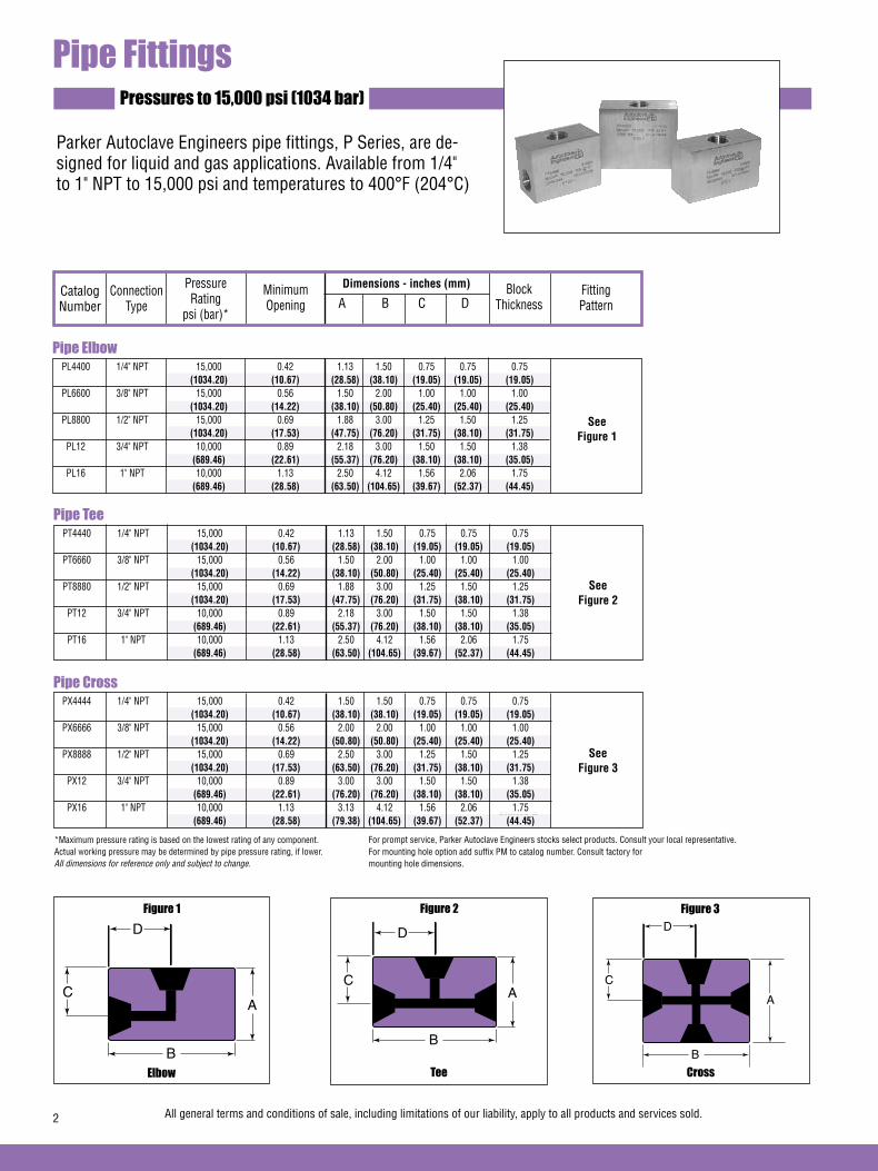
Pipe Elbow PL4400 1/4" NPT 15,000 0.42 1.13 1.50 0.75 0.75 0.75 (1034.20) (10.67) (28.58) (38.10) (19.05) (19.05) (19.05) PL6600 3/8" NPT 15,000 0.56 1.50 2.00 1.00 1.00 1.00 (1034.20) (14.22) (38.10) (50.80) (25.40) (25.40) (25.40) PL8800 1/2" NPT 15,000 0.69 1.88 3.00 1.25 1.50 1.25 (1034.20) (17.53) (47.75) (76.20) (31.75) (38.10) (31.75) PL12 3/4" NPT 10,000 0.89 2.18 3.00 1.50 1.50 1.38 (689.46) (22.61) (55.37) (76.20) (38.10) (38.10) (35.05) PL16 1" NPT 10,000 1.13 2.50 4.12 1.56 2.06 1.75 (689.46) (28.58) (63.50) (104.65) (39.67) (52.37) (44.45)
Dimensions - inches (mm)
Pipe FittingsPressures to 15,000 psi (1034 bar)
See Figure 1
Parker Autoclave Engineers pipe fittings, P Series, are de-signed for liquid and gas applications. Available from 1/4" to 1" NPT to 15,000 psi and temperatures to 400°F (204°C)
Catalog Number
Connection Type
Pressure Rating
psi (bar)*
Minimum Opening
Block Thickness
Fitting Pattern A B C D
Cross
Figure 3*Maximum pressure rating is based on the lowest rating of any component. Actual working pressure may be determined by pipe pressure rating, if lower.All dimensions for reference only and subject to change.
2 All general terms and conditions of sale, including limitations of our liability, apply to all products and services sold.
For mounting hole option add suffix PM to catalog number. Consult factory for mounting hole dimensions.
Pipe Tee PT4440 1/4" NPT 15,000 0.42 1.13 1.50 0.75 0.75 0.75 (1034.20) (10.67) (28.58) (38.10) (19.05) (19.05) (19.05) PT6660 3/8" NPT 15,000 0.56 1.50 2.00 1.00 1.00 1.00 (1034.20) (14.22) (38.10) (50.80) (25.40) (25.40) (25.40) PT8880 1/2" NPT 15,000 0.69 1.88 3.00 1.25 1.50 1.25 (1034.20) (17.53) (47.75) (76.20) (31.75) (38.10) (31.75) PT12 3/4" NPT 10,000 0.89 2.18 3.00 1.50 1.50 1.38 (689.46) (22.61) (55.37) (76.20) (38.10) (38.10) (35.05) PT16 1" NPT 10,000 1.13 2.50 4.12 1.56 2.06 1.75 (689.46) (28.58) (63.50) (104.65) (39.67) (52.37) (44.45)
See Figure 2
Pipe Cross PX4444 1/4" NPT 15,000 0.42 1.50 1.50 0.75 0.75 0.75 (1034.20) (10.67) (38.10) (38.10) (19.05) (19.05) (19.05) PX6666 3/8" NPT 15,000 0.56 2.00 2.00 1.00 1.00 1.00 (1034.20) (14.22) (50.80) (50.80) (25.40) (25.40) (25.40) PX8888 1/2" NPT 15,000 0.69 2.50 3.00 1.25 1.50 1.25 (1034.20) (17.53) (63.50) (76.20) (31.75) (38.10) (31.75) PX12 3/4" NPT 10,000 0.89 3.00 3.00 1.50 1.50 1.38 (689.46) (22.61) (76.20) (76.20) (38.10) (38.10) (35.05) PX16 1" NPT 10,000 1.13 3.13 4.12 1.56 2.06 1.75 (689.46) (28.58) (79.38) (104.65) (39.67) (52.37) (44.45)
See Figure 3
Elbow
Figure 1
D HEX
D
A
B
C
Tee
Figure 2
D
A
B
C
D
A
B
C
Figure 3
For prompt service, Parker Autoclave Engineers stocks select products. Consult your local representative.

All general terms and conditions of sale, including limitations of our liability, apply to all products and services sold. 3
NOTE: NPT (Pipe) Connections:- NPT threads must be sealed using a high quality PTFE tape and/or paste product. Refer to thread sealant manufacturer's instructions on how to apply thread sealant.- Sealing performance may vary based on many factors such as pressure, temperature, media, thread quality, thread material, proper thread engagement and proper use of thread sealant.- Customer should limit the number of times an NPT fitting is assembled and disassembled because thread deformation during assembly will result in deteriorating seal quality over time. When using only PTFE tape, consider using thread lubrication to prevent galling of mating parts.
NOTE: Special material components may be supplied with four flats in place of standard hex.
Coupling
Figure 4
Bulkhead Coupling
Figure 5
*Maximum pressure rating is based on the lowest rating of any component. + distance across flats
(A=Panel hole drill size)
Pipe Coupling 15F4488 1/4" NPT 15,000 0.42 .075 1.50 (1034.20) (10.67) (19.05) (38.10) 15F6688 3/8" NPT 15,000 0.56 1.00 1.63 (1034.20) (14.22) (25.40) (41.28) 15F8888 1/2" NPT 15,000 0.69 1.19 2.00 (1034.20) (17.53) (30.23) (50.80) 10F121288 3/4" NPT 10,000 0.89 1.38 2.75 (689.46) (22.61) (30.06) (69.90) 10F161688 1" NPT 10,000 1.13 1.75 2.50 (689.46) (28.58) (44.50) (63.50)
Dimensions - in.(mm)
See Figure 4
Catalog Number
Connection Type
Pressure Rating
psi (bar)*
Minimum Opening A B
Pipe Bulkhead Coupling 15BF4488 1/4" NPT 15,000 0.42 0.94 2.00 1.00 0.63 0.38 (1034.20) (10.67) (23.80) (50.80) (25.40) (15.75) (9.53) 15BF6688 3/8" NPT 15,000 0.56 1.13 2.38 1.38 0.79 0.38 (1034.20) (14.22) (28.60) (60.50) (35.05) (20.07) (9.53) 15BF8888 1/2" NPT 15,000 0.69 1.68 2.63 1.88 0.91 0.38 (1034.20) (17.53) (42.67) (66.80) (47.80) (23.11) (9.53) 10BF121288 3/4" NPT 10,000 0.89 1.68 2.63 1.88 0.91 0.38 (689.46) (22.61) (42.67) (66.80) (47.80) (23.11) (9.53) 10BF161688 1" NPT 10,000 1.13 1.94 3.50 1.87+ 1.50 0.38 (689.46) (28.58) (49.28) (88.90) (47.50) (38.10) (9.53)
See Figure 5
Dimensions - inches (mm)Catalog Number
Connection Type
Pressure Rating
psi (bar)*
Minimum Opening
E Max
Fitting Pattern A B C D
Fitting Pattern
A HEX
B
E MAX
B
D
AC
HEX
All dimensions for reference only and subject to change.For prompt service, Parker Autoclave Engineers stocks select products. Consult your local representative.
Pipe Plugs PP40 1/4" NPT 15,000 0.63 1.12 (1034.20) (16.00) (28.45) PP60 3/8" NPT 15,000 0.75 1.12 (1034.20) (19.05) (28.45) PP80 1/2" NPT 15,000 1.00 1.50 (1034.20) (25.40) (38.10) PP120 3/4" NPT 10,000 1.38 1.50 (689.46) (35.05) (38.10) PP160 1" NPT 10,000 1.38 1.88 (689.46) (35.05) (47.75)
Dimensions - in.(mm)
See Figure 6
Catalog Number
Connection Type
Pressure Rating
psi (bar)* A B
Fitting Pattern
Figure 6
Plugs
B
A HEX
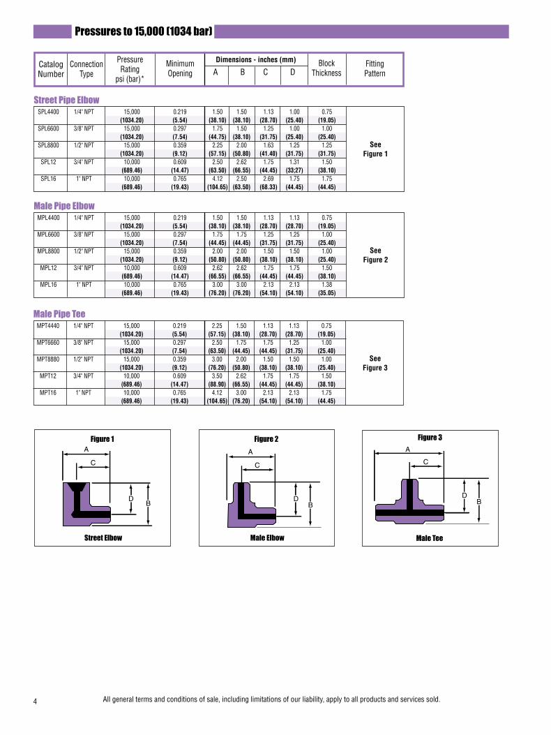
4 All general terms and conditions of sale, including limitations of our liability, apply to all products and services sold.
Street Pipe Elbow SPL4400 1/4" NPT 15,000 0.219 1.50 1.50 1.13 1.00 0.75 (1034.20) (5.54) (38.10) (38.10) (28.70) (25.40) (19.05) SPL6600 3/8" NPT 15,000 0.297 1.75 1.50 1.25 1.00 1.00 (1034.20) (7.54) (44.75) (38.10) (31.75) (25.40) (25.40) SPL8800 1/2" NPT 15,000 0.359 2.25 2.00 1.63 1.25 1.25 (1034.20) (9.12) (57.15) (50.80) (41.40) (31.75) (31.75) SPL12 3/4" NPT 10,000 0.609 2.50 2.62 1.75 1.31 1.50 (689.46) (14.47) (63.50) (66.55) (44.45) (33;27) (38.10) SPL16 1" NPT 10,000 0.765 4.12 2.50 2.69 1.75 1.75 (689.46) (19.43) (104.65) (63.50) (68.33) (44.45) (44.45)
Dimensions - inches (mm)Catalog Number
Connection Type
Pressure Rating
psi (bar)*
Minimum Opening
Block Thickness
Fitting Pattern A B C D
See Figure 1
Male Pipe Elbow MPL4400 1/4" NPT 15,000 0.219 1.50 1.50 1.13 1.13 0.75 (1034.20) (5.54) (38.10) (38.10) (28.70) (28.70) (19.05) MPL6600 3/8" NPT 15,000 0.297 1.75 1.75 1.25 1.25 1.00 (1034.20) (7.54) (44.45) (44.45) (31.75) (31.75) (25.40) MPL8800 1/2" NPT 15,000 0.359 2.00 2.00 1.50 1.50 1.00 (1034.20) (9.12) (50.80) (50.80) (38.10) (38.10) (25.40) MPL12 3/4" NPT 10,000 0.609 2.62 2.62 1.75 1.75 1.50 (689.46) (14.47) (66.55) (66.55) (44.45) (44.45) (38.10) MPL16 1" NPT 10,000 0.765 3.00 3.00 2.13 2.13 1.38 (689.46) (19.43) (76.20) (76.20) (54.10) (54.10) (35.05)
See Figure 2
Pressures to 15,000 (1034 bar)
Male Pipe Tee MPT4440 1/4" NPT 15,000 0.219 2.25 1.50 1.13 1.13 0.75 (1034.20) (5.54) (57.15) (38.10) (28.70) (28.70) (19.05) MPT6660 3/8" NPT 15,000 0.297 2.50 1.75 1.75 1.25 1.00 (1034.20) (7.54) (63.50) (44.45) (44.45) (31.75) (25.40) MPT8880 1/2" NPT 15,000 0.359 3.00 2.00 1.50 1.50 1.00 (1034.20) (9.12) (76.20) (50.80) (38.10) (38.10) (25.40) MPT12 3/4" NPT 10,000 0.609 3.50 2.62 1.75 1.75 1.50 (689.46) (14.47) (88.90) (66.55) (44.45) (44.45) (38.10) MPT16 1" NPT 10,000 0.765 4.12 3.00 2.13 2.13 1.75 (689.46) (19.43) (104.65) (76.20) (54.10) (54.10) (44.45)
See Figure 3
Male Tee
Figure 3A
C
DB
A
C
DB
A
C
DB
A
C
DB
B
A HEXD
B
A
C
A
C
DB
A
C
DB
A
C
DB
A
C
DB
B
A HEXD
B
A
C
A
C
DB
A
C
DB
A
C
DB
A
C
DB
B
A HEXD
B
A
C
Figure 1
Street Elbow
Figure 2
Male Elbow
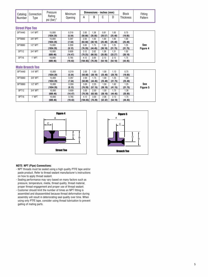
5
Street Pipe Tee SPT4440 1/4" NPT 15,000 0.219 2.00 1.38 0.81 1.00 0.75 (1034.20) (5.54) (50.80) (35.05) (20.57) (25.40) (19.05) SPT6660 3/8" NPT 15,000 0.297 2.50 1.50 1.00 1.00 1.00 (1034.20) (7.54) (63.50) (38.10) (25.40) (25.40) (25.40) SPT8880 1/2" NPT 15,000 0.359 3.00 1.75 1.50 1.25 1.25 (1034.20) (9.12) (76.20) (44.45) (38.10) (31.75) (31.75) SPT12 3/4" NPT 10,000 0.609 3.12 2.62 1.38 1.31 1.50 (689.46) (14.47) (79.25) (66.55) (35.05) (33.27) (38.10) SPT16 1" NPT 10,000 0.765 4.12 3.00 2.13 2.13 1.75 (689.46) (19.43) (104.65) (76.20) (54.10) (54.10) (44.45)
See Figure 4
A
C
DB
A
C
DB
A
C
DB
A
C
DB
B
A HEXD
B
A
C
Street Tee
Figure 4
Dimensions - inches (mm)Catalog Number
Connection Type
Pressure Rating
psi (bar)*
Minimum Opening
Block Thickness
Fitting Pattern A B C D
Male Branch Tee BPT4440 1/4" NPT 15,000 0.219 2.00 1.50 1.00 1.13 0.75 (1034.20) (5.54) (50.80) (38.10) (25.40) (28.70) (19.05) BPT6660 3/8" NPT 15,000 0.297 2.00 1.75 1.00 1.25 1.00 (1034.20) (7.54) (50.80) (44.45) (25.40) (31.75) (25.40) BPT8880 1/2" NPT 15,000 0.359 3.00 2.25 1.50 1.62 1.25 (1034.20) (9.12) (76.20) (57.15) (38.10) (41.15) (31.75) BPT12 3/4" NPT 10,000 0.609 3.00 2.50 1.50 1.75 1.38 (689.46) (14.47) (76.20) (63.50) (38.10) (44.45) (35.05) BPT16 1" NPT 10,000 0.765 4.12 3.00 2.06 2.13 1.75 (689.46) (19.43) (104.65) (76.20) (52.32) (54.10) (44.45)
See Figure 5
Branch Tee
Figure 5
DB
A
C
NOTE: NPT (Pipe) Connections:- NPT threads must be sealed using a high quality PTFE tape and/or paste product. Refer to thread sealant manufacturer's instructions on how to apply thread sealant.- Sealing performance may vary based on many factors such as pressure, temperature, media, thread quality, thread material, proper thread engagement and proper use of thread sealant.- Customer should limit the number of times an NPT fitting is assembled and disassembled because thread deformation during assembly will result in deteriorating seal quality over time. When using only PTFE tape, consider using thread lubrication to prevent galling of mating parts.

All general terms and conditions of sale, including limitations of our liability, apply to all products and services sold.6
Pressures to 15,000 psi (1034 bar)
Pipe Hex Nipples
For rapid system make-up, Parker Autoclave Engineers supplies pipe nipples in various sizes and lengths for pipe valves and fittings.Special lengthsIn addition to the standard lengths listed in the table below, nipples are available in custom lengths. Consult factory.
Special material filters may be supplied with four flats in place of standard hex.
*Maximum pressure rating is based on the lowest rating of any component. Actual working pressure may be determined by tubing pressure rating, if lower.
All dimensions for reference only and subject to change.
Dimensions - in.(mm)Catalog Number
Connection Type
Pressure Rating
psi (bar)*
Minimum Opening A Hex B
Pipe Hex Close Nipples 15MAP4P4 1/4" NPT 15,000 0.219 0.63 1.81 (1034.20) (5.54) (16.00) (46.02) 15MAP6P6 3/8" NPT 15,000 0.297 0.75 1.88 (1034.20) (7.54) (19.05) (47.63) 15MAP8P8 1/2" NPT 15,000 0.359 0.94 2.50 (1034.20) (9.12) (23.88) (63.50) 10MAP12P12 3/4" NPT 10,000 0.609 1.19 2.50 (689.46) (14.47) (30.23) (63.50) 10MAP16P16 1" NPT 10,000 0.765 1.38 3.19 (689.46) (19.43) (35.05) (81.03)
See Figure 1
Pipe Hex Nipples 15MAP4P4-4 1/4" NPT 15,000 0.219 0.63 4.00 (1034.20) (5.54) (16.00) (101.60) 15MAP4P4-6 1/4" NPT 15,000 0.219 0.63 6.00 (1034.20) (5.54) (16.00) (152.40) 15MAP4P4-8 1/4" NPT 15,000 0.219 0.63 8.00 (1034.20) (5.54) (16.00) (203.20) 15MAP6P6-4 3/8" NPT 15,000 0.297 0.75 4.00 (1034.20) (7.54) (19.05) (101.60) 15MAP6P6-6 3/8" NPT 15,000 0.297 0.75 6.00 (1034.20) (7.54) (19.05) (152.40)
See Figure 1
15MAP6P6-8 3/8" NPT 15,000 0.297 0.75 8.00 (1034.20) (7.54) (19.05) (203.20) 15MAP8P8-4 1/2" NPT 15,000 0.359 0.94 4.00 (1034.20) (9.12) (23.88) (101.60) 15MAP8P8-6 1/2" NPT 15,000 0.359 0.94 6.00 (1034.20) (9.12) (23.88) (152.40) 15MAP8P8-8 1/2" NPT 15,000 0.359 0.94 8.00 (1034.20) (9.12) (23.88) (203.20) 10MAP12P12-4 3/4" NPT 10,000 0.609 1.19 4.00 (689.46) (14.47) (30.23) (101.60)10MAP12P12-6 3/4" NPT 10,000 0.609 1.19 6.00 (689.46) (14.47) (30.23) (152.40) 10MAP12P12-8 3/4" NPT 10,000 0.609 1.19 8.00 (689.46) (14.47) (30.23) (203.20) 10MAP16P16-4 1" NPT 10,000 0.765 1.38 4.00 (689.46) (19.43) (35.05) (101.60) 10MAP16P16-6 1" NPT 10,000 0.765 1.38 6.00 (689.46) (19.43) (35.05) (152.40) 10MAP16P16-8 1" NPT 10,000 0.765 1.38 8.00 (689.46) (19.43) (35.05) (203.20)
B
A HEX
Pipe Nipple
Figure 1
Pipe Hex Reducer Nipples 15MAP4P6 1/4" to 3/8" NPT 15,000 0.203 0.75 1.88 (1034.20) (5.16) (19.05) (47.75) 15MAP4P8 1/4" to 1/2" NPT 15,000 0.203 0.94 2.31 (1034.20) (5.16) (23.88) (58.67) 10MAP8P16 1/2" to 1" NPT 10,000 0.375 1.38 2.88 (689.46) (9.53) (35.05) (73.15) 10MAP12P16 3/4" to 1" NPT 10,000 0.500 1.38 2.94 (689.46) (12.70) (35.05) (74.68)
Fitting Pattern
See Figure 2
Figure 2
Reducer Nipple
B
A HEX

7
Pipe Check ValvesPressures to 15,000 (1034 bar)
Provides unidirectional flow and tight shut-off for liquids and gas with high reliability. When differential drops below crack-ing pressure*, valve shuts off. (Not for use as relief valve.)
Materials: 316 Stainless Steel: body, cover, poppet, cover gland. 300 Series Stainless Steel: springStandard O-ring: Viton, for operation to 400° F (204°C). Buna-N or PTFE available for 250°F (121°C) or 400°F (204°C) respectively; specify when ordering.
*Cracking Pressure: 20 psi (1.38 bar) ±30%. Springs for higher cracking pressures (up to 100 psi (6.89 bar)) available on special order for O-ring style check valves only.
Prevents reverse flow where leak-tight shut-off is not manda-tory. When differential drops below cracking pressure, valve closes. With all-metal components, valve can be used up to 400°F (204°C). See Technical Information section for connec-tion temperature limitations. (Not for use as a relief valve.)
Ball and poppet are an integral design to assure positive, in-line seating without “chatter”. Poppet is designed essen-tially for axial flow with minimum pressure drop.
Materials: 316 Stainless Steel: body, cover, ball poppet, cover gland. 300 Series Stainless Steel: ball, spring.
Pipe O-Ring Check Valves
Pipe Ball Check Valves
CAUTION: While testing has shown O-Rings to provide satisfactory service life, both cyclic and shelf life may vary widely with differing service conditions, properties of reactants, pressure and temperature cycling and age of the O-ring. FREQUENT INSPECTIONS SHOULD BE MADE to detect any deterioration, and O-rings replaced as required.
Special material check valves may be supplied with four flats in place of standard hex.
Minimum operating temperature for standard o-ring check valves 0°F (-17.8°C).
Minimum operating temperature for pipe ball check valves 0°F (-17.8°C).
FLOW
FLOWFLOW
FLOW
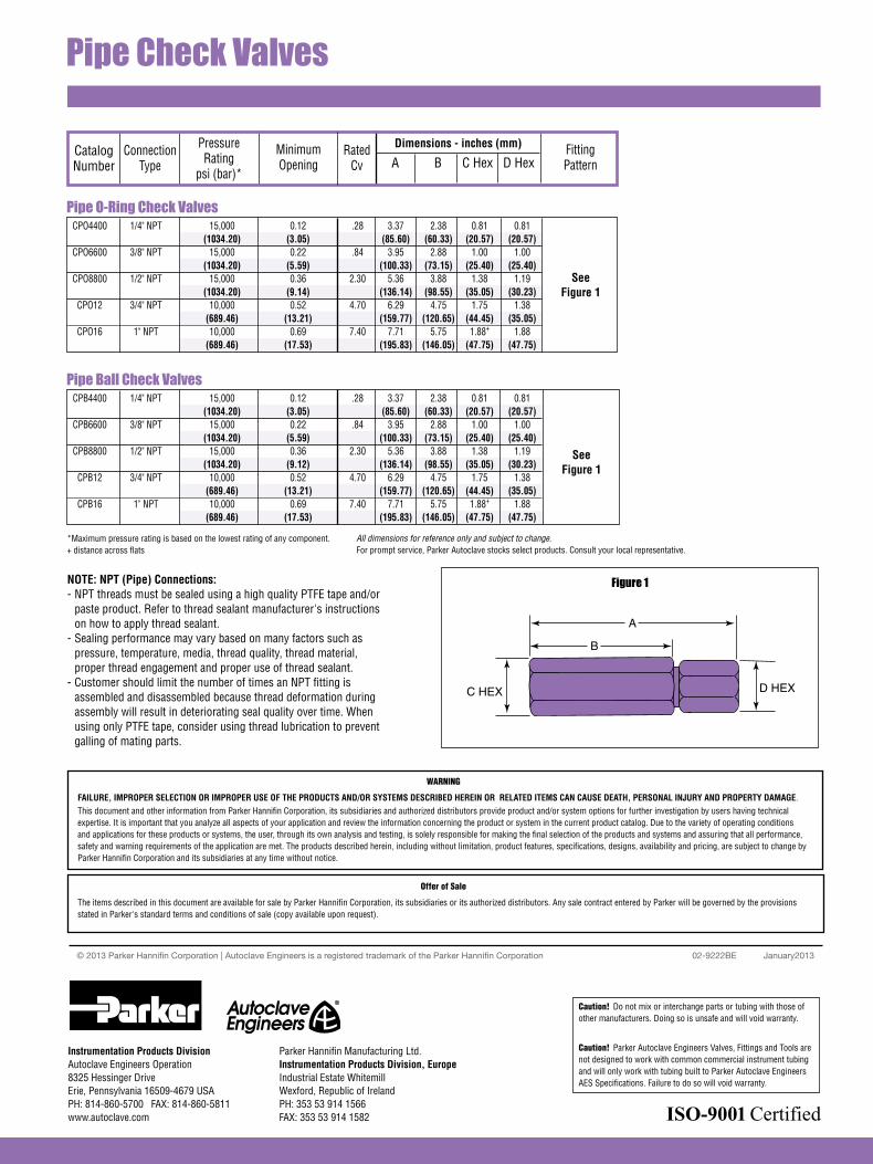
Pipe Check Valves
Figure 1
*Maximum pressure rating is based on the lowest rating of any component.+ distance across flats
All dimensions for reference only and subject to change.For prompt service, Parker Autoclave stocks select products. Consult your local representative.
Pipe O-Ring Check Valves CPO4400 1/4" NPT 15,000 0.12 .28 3.37 2.38 0.81 0.81 (1034.20) (3.05) (85.60) (60.33) (20.57) (20.57) CPO6600 3/8" NPT 15,000 0.22 .84 3.95 2.88 1.00 1.00 (1034.20) (5.59) (100.33) (73.15) (25.40) (25.40) CPO8800 1/2" NPT 15,000 0.36 2.30 5.36 3.88 1.38 1.19 (1034.20) (9.14) (136.14) (98.55) (35.05) (30.23) CPO12 3/4" NPT 10,000 0.52 4.70 6.29 4.75 1.75 1.38 (689.46) (13.21) (159.77) (120.65) (44.45) (35.05) CPO16 1" NPT 10,000 0.69 7.40 7.71 5.75 1.88+ 1.88 (689.46) (17.53) (195.83) (146.05) (47.75) (47.75)
See Figure 1
Catalog Number
Connection Type
Pressure Rating
psi (bar)*
Minimum Opening
Dimensions - inches (mm) Fitting Pattern A B C Hex D Hex
Pipe Ball Check Valves CPB4400 1/4" NPT 15,000 0.12 .28 3.37 2.38 0.81 0.81 (1034.20) (3.05) (85.60) (60.33) (20.57) (20.57) CPB6600 3/8" NPT 15,000 0.22 .84 3.95 2.88 1.00 1.00 (1034.20) (5.59) (100.33) (73.15) (25.40) (25.40) CPB8800 1/2" NPT 15,000 0.36 2.30 5.36 3.88 1.38 1.19 (1034.20) (9.12) (136.14) (98.55) (35.05) (30.23) CPB12 3/4" NPT 10,000 0.52 4.70 6.29 4.75 1.75 1.38 (689.46) (13.21) (159.77) (120.65) (44.45) (35.05) CPB16 1" NPT 10,000 0.69 7.40 7.71 5.75 1.88+ 1.88 (689.46) (17.53) (195.83) (146.05) (47.75) (47.75)
See Figure 1
B
A
D HEXC HEX
Rated Cv
NOTE: NPT (Pipe) Connections:- NPT threads must be sealed using a high quality PTFE tape and/or paste product. Refer to thread sealant manufacturer's instructions on how to apply thread sealant.- Sealing performance may vary based on many factors such as pressure, temperature, media, thread quality, thread material, proper thread engagement and proper use of thread sealant.- Customer should limit the number of times an NPT fitting is assembled and disassembled because thread deformation during assembly will result in deteriorating seal quality over time. When using only PTFE tape, consider using thread lubrication to prevent galling of mating parts.
02-9222BE January2013© 2013 Parker Hannifin Corporation | Autoclave Engineers is a registered trademark of the Parker Hannifin Corporation
Parker Hannifin Manufacturing Ltd. Instrumentation Products Division, Europe Industrial Estate WhitemillWexford, Republic of IrelandPH: 353 53 914 1566FAX: 353 53 914 1582
Instrumentation Products DivisionAutoclave Engineers Operation8325 Hessinger DriveErie, Pennsylvania 16509-4679 USAPH: 814-860-5700 FAX: 814-860-5811www.autoclave.com
WARNING
FAILURE, IMPROPER SELECTION OR IMPROPER USE OF THE PRODUCTS AND/OR SYSTEMS DESCRIBED HEREIN OR RELATED ITEMS CAN CAUSE DEATH, PERSONAL INJURY AND PROPERTY DAMAGE.This document and other information from Parker Hannifin Corporation, its subsidiaries and authorized distributors provide product and/or system options for further investigation by users having technical expertise. It is important that you analyze all aspects of your application and review the information concerning the product or system in the current product catalog. Due to the variety of operating conditions and applications for these products or systems, the user, through its own analysis and testing, is solely responsible for making the final selection of the products and systems and assuring that all performance, safety and warning requirements of the application are met. The products described herein, including without limitation, product features, specifications, designs, availability and pricing, are subject to change by Parker Hannifin Corporation and its subsidiaries at any time without notice.
Offer of Sale
The items described in this document are available for sale by Parker Hannifin Corporation, its subsidiaries or its authorized distributors. Any sale contract entered by Parker will be governed by the provisions stated in Parker's standard terms and conditions of sale (copy available upon request).
ISO-9001 Certified
Caution! Do not mix or interchange parts or tubing with those of other manufacturers. Doing so is unsafe and will void warranty.
Caution! Parker Autoclave Engineers Valves, Fittings and Tools are not designed to work with common commercial instrument tubing and will only work with tubing built to Parker Autoclave Engineers AES Specifications. Failure to do so will void warranty.
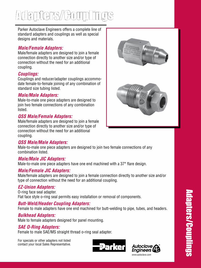
Adapters/Couplings Adapters/Couplings
Parker Autoclave Engineers offers a complete line of standard adapters and couplings as well as special designs and materials.
Male/Female Adapters:Male/female adapters are designed to join a female connection directly to another size and/or type of connection without the need for an additional coupling.
Couplings:Couplings and reducer/adapter couplings accommo-date female-to-female joining of any combination of standard size tubing listed.
Male/Male Adapters:Male-to-male one piece adapters are designed to join two female connections of any combination listed.
QSS Male/Female Adapters:Male/female adapters are designed to join a female connection directly to another size and/or type of connection without the need for an additional coupling.
QSS Male/Male Adapters:Male-to-male one piece adapters are designed to join two female connections of any combination listed.
Male/Male JIC Adapters:Male-to-male one piece adapters have one end machined with a 37° flare design.
Male/Female JIC Adapters:Male/female adapters are designed to join a female connection directly to another size and/ortype of connection without the need for an additional coupling.
EZ-Union Adapters:O-ring face seal adapter. Flat face style o-ring seal permits easy installation or removal of components.
Butt-Weld/Header Coupling Adapters:Female to male adapters have one end machined for butt-welding to pipe, tubes, and headers.
Bulkhead Adapters:Male to female adapters designed for panel mounting.
SAE O-Ring Adapters:Female to male SAE/MS straight thread o-ring seal adapter.
For specials or other adapters not listed contact your local Sales Representative.
www.autoclave.com
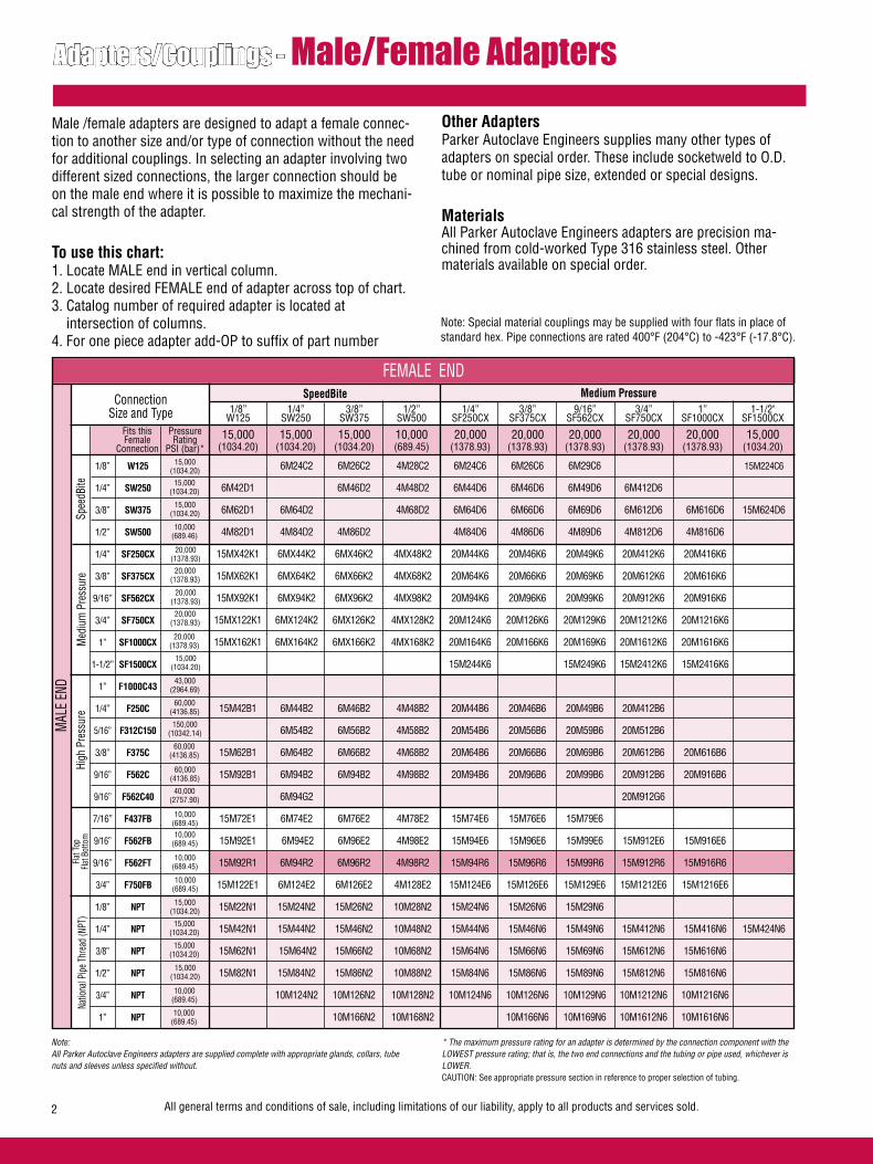
All general terms and conditions of sale, including limitations of our liability, apply to all products and services sold.2
Adapters/Couplings - Male/Female AdaptersMale /female adapters are designed to adapt a female connec-tion to another size and/or type of connection without the need for additional couplings. In selecting an adapter involving two different sized connections, the larger connection should be on the male end where it is possible to maximize the mechani-cal strength of the adapter. To use this chart:1. Locate MALE end in vertical column.2. Locate desired FEMALE end of adapter across top of chart.3. Catalog number of required adapter is located at intersection of columns.4. For one piece adapter add-OP to suffix of part number
ConnectionSize and Type
SpeedBite
Spee
dBite
Med
ium
Pre
ssur
eFla
t Top
Fla
t Bot
tom
Note:All Parker Autoclave Engineers adapters are supplied complete with appropriate glands, collars, tube nuts and sleeves unless specified without.
Other AdaptersParker Autoclave Engineers supplies many other types of adapters on special order. These include socketweld to O.D. tube or nominal pipe size, extended or special designs.
MaterialsAll Parker Autoclave Engineers adapters are precision ma-chined from cold-worked Type 316 stainless steel. Other materials available on special order.
1/8” W125 6M24C2 6M26C2 4M28C2 6M24C6 6M26C6 6M29C6 15M224C6
1/4” SW250 6M42D1 6M46D2 4M48D2 6M44D6 6M46D6 6M49D6 6M412D6
3/8” SW375 6M62D1 6M64D2 4M68D2 6M64D6 6M66D6 6M69D6 6M612D6 6M616D6 15M624D6
1/2” SW500 4M82D1 4M84D2 4M86D2 4M84D6 4M86D6 4M89D6 4M812D6 4M816D6
1/4” SF250CX 15MX42K1 6MX44K2 6MX46K2 4MX48K2 20M44K6 20M46K6 20M49K6 20M412K6 20M416K6
3/8” SF375CX 15MX62K1 6MX64K2 6MX66K2 4MX68K2 20M64K6 20M66K6 20M69K6 20M612K6 20M616K6
9/16” SF562CX 15MX92K1 6MX94K2 6MX96K2 4MX98K2 20M94K6 20M96K6 20M99K6 20M912K6 20M916K6
3/4” SF750CX 15MX122K1 6MX124K2 6MX126K2 4MX128K2 20M124K6 20M126K6 20M129K6 20M1212K6 20M1216K6
1” SF1000CX 15MX162K1 6MX164K2 6MX166K2 4MX168K2 20M164K6 20M166K6 20M169K6 20M1612K6 20M1616K6
1-1/2” SF1500CX 15M244K6 15M249K6 15M2412K6 15M2416K6
1” F1000C43
1/4” F250C 15M42B1 6M44B2 6M46B2 4M48B2 20M44B6 20M46B6 20M49B6 20M412B6
5/16” F312C150 6M54B2 6M56B2 4M58B2 20M54B6 20M56B6 20M59B6 20M512B6
3/8” F375C 15M62B1 6M64B2 6M66B2 4M68B2 20M64B6 20M66B6 20M69B6 20M612B6 20M616B6
9/16” F562C 15M92B1 6M94B2 6M94B2 4M98B2 20M94B6 20M96B6 20M99B6 20M912B6 20M916B6
9/16” F562C40 6M94G2 20M912G6
7/16” F437FB 15M72E1 6M74E2 6M76E2 4M78E2 15M74E6 15M76E6 15M79E6
9/16” F562FB 15M92E1 6M94E2 6M96E2 4M98E2 15M94E6 15M96E6 15M99E6 15M912E6 15M916E6
9/16” F562FT 15M92R1 6M94R2 6M96R2 4M98R2 15M94R6 15M96R6 15M99R6 15M912R6 15M916R6
3/4” F750FB 15M122E1 6M124E2 6M126E2 4M128E2 15M124E6 15M126E6 15M129E6 15M1212E6 15M1216E6
1/8” NPT 15M22N1 15M24N2 15M26N2 10M28N2 15M24N6 15M26N6 15M29N6
1/4” NPT 15M42N1 15M44N2 15M46N2 10M48N2 15M44N6 15M46N6 15M49N6 15M412N6 15M416N6 15M424N6
3/8” NPT 15M62N1 15M64N2 15M66N2 10M68N2 15M64N6 15M66N6 15M69N6 15M612N6 15M616N6
1/2” NPT 15M82N1 15M84N2 15M86N2 10M88N2 15M84N6 15M86N6 15M89N6 15M812N6 15M816N6
3/4” NPT 10M124N2 10M126N2 10M128N2 10M124N6 10M126N6 10M129N6 10M1212N6 10M1216N6
1” NPT 10M166N2 10M168N2 10M166N6 10M169N6 10M1612N6 10M1616N6
Medium Pressure
High
Pre
ssur
eNa
tiona
l Pipe
Thr
ead
(NPT
)
* The maximum pressure rating for an adapter is determined by the connection component with the LOWEST pressure rating; that is, the two end connections and the tubing or pipe used, whichever is LOWER. CAUTION: See appropriate pressure section in reference to proper selection of tubing.
15,000(1034.20)
15,000(1034.20)
15,000(1034.20)
10,000(689.46)
20,000(1378.93)
20,000(1378.93)
20,000(1378.93)
20,000(1378.93)
20,000(1378.93)
43,000(2964.69)
60,000(4136.85)
150,000(10342.14)
60,000(4136.85)
60,000(4136.85)
40,000(2757.90)
10,000(689.45)10,000
(689.45)
10,000(689.45)
10,000(689.45)
15,000(1034.20)
15,000(1034.20)
15,000(1034.20)
15,000(1034.20)
10,000(689.45)
10,000(689.45)
Note: Special material couplings may be supplied with four flats in place of standard hex. Pipe connections are rated 400°F (204°C) to -423°F (-17.8°C).
FEMALE END
MAL
E EN
D
1/8” 1/4” 3/8” 1/2” 1/4” 3/8” 9/16” 3/4” 1” 1-1/2" W125 SW250 SW375 SW500 SF250CX SF375CX SF562CX SF750CX SF1000CX SF1500CX
15,000 15,000 15,000 10,000 20,000 20,000 20,000 20,000 20,000 15,000 (1034.20) (1034.20) (1034.20) (689.45) (1378.93) (1378.93) (1378.93) (1378.93) (1378.93) (1034.20)
15,000(1034.20)
Fits this Female
Connection
PressureRating
PSI (bar)*

All general terms and conditions of sale, including limitations of our liability, apply to all products and services sold. 3
High Pressure
6M24C3 6M26C3 6M29C3 15M22C8 15M24C8 15M26C8 15M28C8
6M44D3 6M46D3 6M49D3 15M42D8 15M44D8 15M46D8 15M48D8 10M412D8
6M64D3 6M66D3 6M69D3 15M62D8 15M64D8 15M66D8 15M68D8 10M612D8 10M616D8
4M84D3 4M86D3 4M89D3 10M82D8 10M84D8 10M86D8 10M88D8 10M812D8 10M816D8
20M44K3 20M45K3 20M46K3 20M49K3 15MX42K8 15MX44K8 15MX46K8 15MX48K8 10MX412K8
20M64K3 20M65K3 20M66K3 20M69K3 15MX62K8 15MX64K8 15MX66K8 15MX68K8 10MX612K8 10MX616K8
20M94K3 20M95K3 20M96K3 20M99K3 15MX92K8 15MX94K8 15MX96K8 15MX98K8 10MX912K8 10MX916K8
20M1216K3 20M124K3 20M125K3 20M126K3 20M129K3 20M129K40 15MX124K8 15MX126K8 15MX128K8 10MX1212K8 10MX1216K8
20M164K3 20M166K3 20M169K3 15MX164K8 15MX166K8 15MX168K8 10MX1612K8 10MX1616K8
15M244K8 15M248K8
43M164B3 43M166B3 43M169B3 43M169B40
43M416B3 60M44B3 60M45B3 60M46B3 60M49B3 15M42B8 15M44B8 15M46B8 15M48B8 10M412B8 10M416B8
60M54B3 60M56B3 60M59B3 15M58B8 10M512B8
43M616B3 60M64B3 60M65B3 60M66B3 60M69B3 15M62B8 15M64B8 15M66B8 15M68B8 10M612B8 10M616B8
43M916B3 60M94B3 60M95B3 60M96B3 60M99B3 15M92B8 15M94B8 15M96B8 15M98B8 10M912B8 10M916B8
15M98G8
15M74E3 15M76E3 15M79E3 10M72E8 10M74E8 10M76E8 10M78E8 10M712E8
15M94E3 15M96E3 10M92E8 10M94E8 10M96E8 10M98E8 10M912E8 10M916E8
15M94R3 15M96R3 15M99R3 10M92R8 10M94R8 10M96R8 10M98R8 10M912R8 10M916R8
15M124E3 15M126E3 15M129E3 10M122E8 10M124E8 10M126E8 10M128E8 10M1212E8 10M1216E8
15M24N3 15M26N3 15M29N3 15M24N8
15M44N3 15M45N3 15M46N3 15M49N3 15M42N8 15M46N8 15M48N8
15M64N3 15M66N3 15M69N3 15M69N40 15M64N8 15M68N8
15M84N3 15M86N3 15M89N3 15M89N40 15M84N8 15M86N8 10M812N8
10M124N3 10M126N3 10M129N3 10M122N8 10M124N8 10M128N8
10M166N3 10M169N3 10M168N8
National Pipe Thread (NPT)
Parker Autoclave Engineers Male/Female Adapters are available in a “one-piece” design. They are identi-cal to the two piece designs in length and can be ordered by adding the suffix - OP to the two piece adapter part numbers listed.
Double Cone Plug Double Cone Plug Flat Bottom Gasket Flat Top Gasket Male NPT (Medium Pressure shown) (SpeedBite shown) (Medium Pressure shown) (SpeedBite shown) (High Pressure shown)
For prompt service, Parker Autoclave Engineers stocks select products. Consult factory.
FEMALE END
43,000 60,000 150,000 60,000 60,000 40,000 15,000 15,000 15,000 15,000 10,000 10,000 (2964.69) (4136.85) (10342.14) (4136.85) (4136.85) (2757.90) (1034.20) (1034.20) (1034.20) (1034.20) (689.45) (689.45)
1” 1/4” 5/16” 3/8” 9/16” 9/16” 1/8” 1/4” 3/8” 1/2” 3/4” 1” F1000C43 F250C F312C150 F375C F562C F562C40 NPT NPT NPT NPT NPT NPT
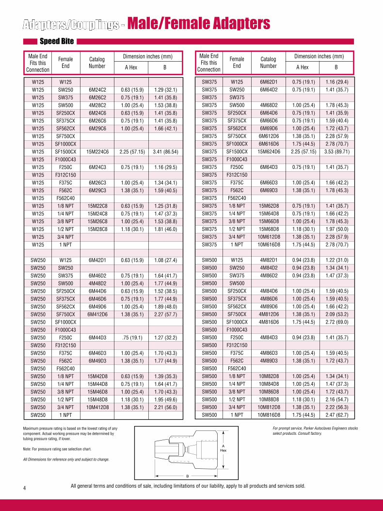
Adapters/Couplings - Male/Female AdaptersSpeed Bite
Female End
Male End Fits this
Connection
CatalogNumber
Dimension inches (mm)
A Hex BFemale
EndCatalogNumber
Dimension inches (mm)
A Hex B
AHex
B
All general terms and conditions of sale, including limitations of our liability, apply to all products and services sold.4
For prompt service, Parker Autoclaves Engineers stocks select products. Consult factory.
Maximum pressure rating is based on the lowest rating of any component. Actual working pressure may be determined by tubing pressure rating, if lower.
Note: For pressure rating see selection chart.
All Dimensions for reference only and subject to change.
Male End Fits this
Connection
W125 W125 W125 SW250 6M24C2 0.63 (15.9) 1.29 (32.1) W125 SW375 6M26C2 0.75 (19.1) 1.41 (35.8) W125 SW500 4M28C2 1.00 (25.4) 1.53 (38.8) W125 SF250CX 6M24C6 0.63 (15.9) 1.41 (35.8) W125 SF375CX 6M26C6 0.75 (19.1) 1.41 (35.8) W125 SF562CX 6M29C6 1.00 (25.4) 1.66 (42.1) W125 SF750CX W125 SF1000CX W125 SF1500CX 15M224C6 2.25 (57.15) 3.41 (86.54) W125 F1000C43 W125 F250C 6M24C3 0.75 (19.1) 1.16 (29.5) W125 F312C150 W125 F375C 6M26C3 1.00 (25.4) 1.34 (34.1) W125 F562C 6M29C3 1.38 (35.1) 1.59 (40.5) W125 F562C40 W125 1/8 NPT 15M22C8 0.63 (15.9) 1.25 (31.8) W125 1/4 NPT 15M24C8 0.75 (19.1) 1.47 (37.3) W125 3/8 NPT 15M26C8 1.00 (25.4) 1.53 (38.8) W125 1/2 NPT 15M28C8 1.18 (30.1) 1.81 (46.0) W125 3/4 NPT W125 1 NPT
SW250 W125 6M42D1 0.63 (15.9) 1.08 (27.4) SW250 SW250 SW250 SW375 6M46D2 0.75 (19.1) 1.64 (41.7) SW250 SW500 4M48D2 1.00 (25.4) 1.77 (44.9) SW250 SF250CX 6M44D6 0.63 (15.9) 1.52 (38.5) SW250 SF375CX 6M46D6 0.75 (19.1) 1.77 (44.9) SW250 SF562CX 6M49D6 1.00 (25.4) 1.89 (48.0) SW250 SF750CX 6M412D6 1.38 (35.1) 2.27 (57.7) SW250 SF1000CX SW250 F1000C43 SW250 F250C 6M44D3 .75 (19.1) 1.27 (32.2) SW250 F312C150 SW250 F375C 6M46D3 1.00 (25.4) 1.70 (43.3) SW250 F562C 6M49D3 1.38 (35.1) 1.77 (44.9) SW250 F562C40 SW250 1/8 NPT 15M42D8 0.63 (15.9) 1.39 (35.3) SW250 1/4 NPT 15M44D8 0.75 (19.1) 1.64 (41.7) SW250 3/8 NPT 15M46D8 1.00 (25.4) 1.70 (43.3) SW250 1/2 NPT 15M48D8 1.18 (30.1) 1.95 (49.6) SW250 3/4 NPT 10M412D8 1.38 (35.1) 2.21 (56.0) SW250 1 NPT
SW375 W125 6M62D1 0.75 (19.1) 1.16 (29.4) SW375 SW250 6M64D2 0.75 (19.1) 1.41 (35.7) SW375 SW375 SW375 SW500 4M68D2 1.00 (25.4) 1.78 (45.3) SW375 SF250CX 6M64D6 0.75 (19.1) 1.41 (35.9) SW375 SF375CX 6M66D6 0.75 (19.1) 1.59 (40.4) SW375 SF562CX 6M69D6 1.00 (25.4) 1.72 (43.7) SW375 SF750CX 6M612D6 1.38 (35.1) 2.28 (57.9) SW375 SF1000CX 6M616D6 1.75 (44.5) 2.78 (70.7) SW375 SF1500CX 15M624D6 2.25 (57.15) 3.53 (89.71) SW375 F1000C43 SW375 F250C 6M64D3 0.75 (19.1) 1.41 (35.7) SW375 F312C150 SW375 F375C 6M66D3 1.00 (25.4) 1.66 (42.2) SW375 F562C 6M69D3 1.38 (35.1) 1.78 (45.3) SW375 F562C40 SW375 1/8 NPT 15M62D8 0.75 (19.1) 1.41 (35.7) SW375 1/4 NPT 15M64D8 0.75 (19.1) 1.66 (42.2) SW375 3/8 NPT 15M66D8 1.00 (25.4) 1.78 (45.3) SW375 1/2 NPT 15M68D8 1.18 (30.1) 1.97 (50.0) SW375 3/4 NPT 10M612D8 1.38 (35.1) 2.28 (57.9) SW375 1 NPT 10M616D8 1.75 (44.5) 2.78 (70.7)
SW500 W125 4M82D1 0.94 (23.8) 1.22 (31.0) SW500 SW250 4M84D2 0.94 (23.8) 1.34 (34.1) SW500 SW375 4M86D2 0.94 (23.8) 1.47 (37.3) SW500 SW500 SW500 SF250CX 4M84D6 1.00 (25.4) 1.59 (40.5) SW500 SF375CX 4M86D6 1.00 (25.4) 1.59 (40.5) SW500 SF562CX 4M89D6 1.00 (25.4) 1.66 (42.2) SW500 SF750CX 4M812D6 1.38 (35.1) 2.09 (53.2) SW500 SF1000CX 4M816D6 1.75 (44.5) 2.72 (69.0) SW500 F1000C43 SW500 F250C 4M84D3 0.94 (23.8) 1.41 (35.7) SW500 F312C150 SW500 F375C 4M86D3 1.00 (25.4) 1.59 (40.5) SW500 F562C 4M89D3 1.38 (35.1) 1.72 (43.7) SW500 F562C40 SW500 1/8 NPT 10M82D8 1.00 (25.4) 1.34 (34.1) SW500 1/4 NPT 10M84D8 1.00 (25.4) 1.47 (37.3) SW500 3/8 NPT 10M86D8 1.00 (25.4) 1.72 (43.7) SW500 1/2 NPT 10M88D8 1.18 (30.1) 2.16 (54.7) SW500 3/4 NPT 10M812D8 1.38 (35.1) 2.22 (56.3) SW500 1 NPT 10M816D8 1.75 (44.5) 2.47 (62.7)

Medium Pressure
Female End
Male End Fits this
Connection
CatalogNumber
Dimension inches (mm)
A Hex BFemale
End
Male End Fits this
Connection
CatalogNumber
Dimension inches (mm)
A Hex B
B
AHex
All general terms and conditions of sale, including limitations of our liability, apply to all products and services sold. 5
For prompt service, Parker Autoclave Engineers stocks select products. Consult factory.
Maximum pressure rating is based on the lowest rating of any component. Actual working pressure may be determined by tubing pressure rating, if lower.
Note: For pressure rating see selection chart.
All Dimensions for reference only and subject to change.
Adapter configurations may vary from outline shown
SF250CX W125 15MX42K1 0.63 (15.9) 1.34 (34.1) SF250CX SW250 6MX44K2 0.63 (15.9) 1.59 (40.5) SF250CX SW375 6MX46K2 0.75 (19.1) 1.59 (40.5) SF250CX SW500 4MX48K2 1.00 (25.4) 1.00 (25.4) SF250CX SF250CX 20M44K6 0.63 (15.9) 1.47 (37.3) SF250CX SF375CX 20M46K6 0.75 (19.1) 1.59 (40.5) SF250CX SF562CX 20M49K6 1.00 (25.4) 1.97 (50.0) SF250CX SF750CX 20M412K6 1.38 (35.1) 2.34 (59.5) SF250CX SF1000CX 20M416K6 1.75 (44.5) 2.84 (72.2) SF250CX F1000C43 SF250CX F250C 20M44K3 0.75 (19.1) 1.28 (32.5) SF250CX F312C150 20M45K3 1.00 (25.4) 2.09 (53.2) SF250CX F375C 20M46K3 1.00 (25.4) 1.59 (40.5) SF250CX F562C 20M49K3 1.38 (35.1) 1.97 (50.0) SF250CX F562C40 SF250CX 1/8 NPT 15MX42K8 0.63 (15.9) 1.47(37.3) SF250CX 1/4 NPT 15MX44K8 0.75 (19.1) 1.59 (40.5) SF250CX 3/8 NPT 15MX46K8 1.00 (25.4) 1.66 (42.2) SF250CX 1/2 NPT 15MX48K8 1.18 (30.1) 1.97 (50.0) SF250CX 3/4 NPT 10MX412K8 1.38 (35.1) 2.09 (53.2) SF250CX 1 NPT
SF375CX W125 15MX62K1 0.63 (15.9) 1.50 (38.1) SF375CX SW250 6MX64K2 0.63 (15.9) 1.63 (41.3) SF375CX SW375 6MX66K2 1.00 (25.4) 1.82 (46.0) SF375CX SW500 4MX68K2 1.00 (25.4) 2.00 (50.8) SF375CX SF250CX 20M64K6 0.63 (15.9) 1.39 (35.2) SF375CX SF375CX 20M66K6 .75 (19.1) 1.66 (42.2) SF375CX SF562CX 20M69K6 1.00 (25.4) 2.06 (52.4) SF375CX SF750CX 20M612K6 1.38 (35.1) 2.50 (63.5) SF375CX SF1000CX 20M616K6 1.75 (44.5) 3.06 (77.8) SF375CX F1000C43 SF375CX F250C 20M64K3 0.75 (19.1) 1.44 (36.5) SF375CX F312C150 20M65K3 1.00 (25.4) 2.25 (57.2) SF375CX F375C 20M66K3 1.00 (25.4) 1.63 (41.3) SF375CX F562C 20M69K3 1.38 (35.1) 1.88 (47.6) SF375CX F562C40 SF375CX 1/8 NPT 15MX62K8 0.63 (15.9) 1.75 (44.5) SF375CX 1/4 NPT 15MX64K8 0.75 (19.1) 1.81 (46.0) SF375CX 3/8 NPT 15MX66K8 1.00 (25.4) 1.88 (47.6) SF375CX 1/2 NPT 15MX68K8 1.18 (30.1) 2.12 (54.0) SF375CX 3/4 NPT 10MX612K8 1.38 (35.1) 2.38 (60.3) SF375CX 1 NPT 10MX616K8 1.75 (44.5) 2.63 (66.7)
SF562CX W125 15MX92K1 0.81 (20.6) 1.75 (44.5) SF562CX SW250 6MX94K2 0.94 (23.8) 1.75 (44.5) SF562CX SW375 6MX96K2 0.94 (23.8) 1.75 (44.5) SF562CX SW500 4MX98K2 1.00 (25.4) 1.94 (49.2) SF562CX SF250CX 20M94K6 0.94 (23.8) 1.34 (34.1) SF562CX SF375CX 20M96K6 0.94 (23.8) 1.34 (59.5) SF562CX SF562CX 20M99K6 1.00 (25.4) 2.00 (50.8) SF562CX SF750CX 20M912K6 1.38 (35.1) 3.12 (79.3) SF562CX SF1000CX 20M916K6 1.75 (44.5) 3.75 (95.3) SF562CX F1000C43 SF562CX F250C 20M94K3 0.81 (20.6) 1.81 (46.0) SF562CX F312C150 20M95K3 1.00 (25.4) 2.50 (63.5) SF562CX F375C 20M96K3 1.00 (25.4) 2.00 (50.8) SF562CX F562C 20M99K3 1.38 (35.1) 2.12 (54.0) SF562CX F562C40 SF562CX 1/8 NPT 15MX92K8 0.94 (23.8) 1.75 (44.5) SF562CX 1/4 NPT 15MX94K8 0.94 (23.8) 2.18 (55.5) SF562CX 3/8 NPT 15MX96K8 0.94 (23.8) 2.18 (55.5) SF562CX 1/2 NPT 15MX98K8 1.18 (30.1) 2.44 (61.9) SF562CX 3/4 NPT 10MX912K8 1.50 (38.1) 2.50 (63.5) SF562CX 1 NPT 10MX916K8 1.75 (44.5) 3.00 (76.2)
SF750CX W125 SF750CX SW250 6MX124K2 1.18 (30.1) 2.06 (52.4) SF750CX SW375 6MX126K2 1.18 (30.1) 1.97 (50.0) SF750CX SW500 4MX128K2 1.18 (30.1) 2.32 (58.72) SF750CX SF250CX 20M124K6 1.18 (30.1) 2.06 (52.4) SF750CX SF375CX 20M126K6 1.18 (30.1) 2.06 (52.4) SF750CX SF562CX 20M129K6 1.18 (30.1) 1.69 (61.9) SF750CX SF750CX 20M1212K6 1.38 (35.1) 2.56 (65.0) SF750CX SF1000CX 20M1216K6 1.75 (44.5) 3.50 (88.9) SF750CX F1000C43 20M1216K3 1.75 (44.5) 3.063 (77.78) SF750CX F250C 20M124K3 1.18 (30.1) 2.06 (52.32) SF750CX F312C150 20M125K3 1.18 (30.1) 3.12 (79.3) SF750CX F375C 20M126K3 1.18 (30.1) 2.06 (52.4) SF750CX F562C 20M129K3 1.38 (35.1) 2.32 (58.93) SF750CX F562C40 20M129K40 1.38 (35.1) 2.38 (60.4) SF750CX 1/8 NPT SF750CX 1/4 NPT 15MX124K8 1.18 (30.1) 2.50 (63.5) SF750CX 3/8 NPT 15MX126K8 1.18 (30.1) 2.88 (73.0) SF750CX 1/2 NPT 15MX128K8 1.18 (30.1) 2.88 (73.0) SF750CX 3/4 NPT 10MX1212K8 1.38 (35.1) 3.12 (79.3) SF750CX 1 NPT 10MX1216K8 1.75 (44.5) 3.50 (88.9)
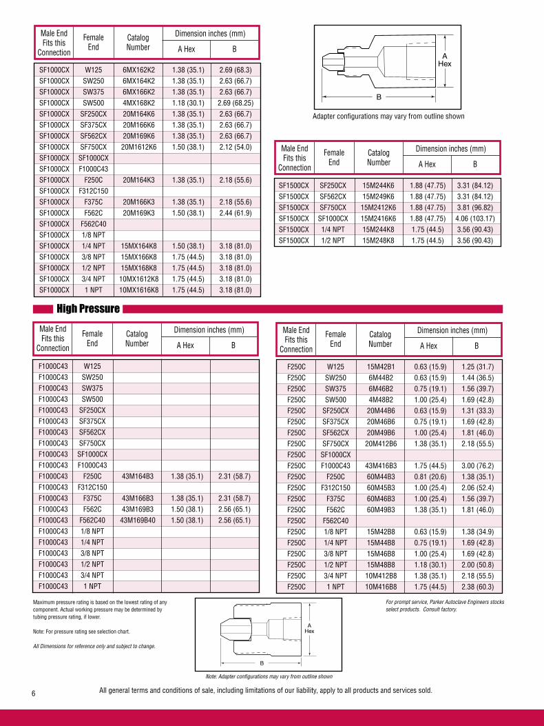
Female End
Male End Fits this
Connection
CatalogNumber
Dimension inches (mm)
A Hex B
High Pressure
Female End
Male End Fits this
Connection
CatalogNumber
Dimension inches (mm)
A Hex B
F1000C43 W125 F1000C43 SW250 F1000C43 SW375 F1000C43 SW500 F1000C43 SF250CX F1000C43 SF375CX F1000C43 SF562CX F1000C43 SF750CX F1000C43 SF1000CX F1000C43 F1000C43 F1000C43 F250C 43M164B3 1.38 (35.1) 2.31 (58.7) F1000C43 F312C150 F1000C43 F375C 43M166B3 1.38 (35.1) 2.31 (58.7) F1000C43 F562C 43M169B3 1.50 (38.1) 2.56 (65.1) F1000C43 F562C40 43M169B40 1.50 (38.1) 2.56 (65.1) F1000C43 1/8 NPT F1000C43 1/4 NPT F1000C43 3/8 NPT F1000C43 1/2 NPT F1000C43 3/4 NPT F1000C43 1 NPT
Female End
Male End Fits this
Connection
CatalogNumber
Dimension inches (mm)
A Hex B
B
AHex
B
AHex
All general terms and conditions of sale, including limitations of our liability, apply to all products and services sold.6
For prompt service, Parker Autoclave Engineers stocks select products. Consult factory.
Maximum pressure rating is based on the lowest rating of any component. Actual working pressure may be determined by tubing pressure rating, if lower.
Note: For pressure rating see selection chart.
All Dimensions for reference only and subject to change.
Adapter configurations may vary from outline shown
Note: Adapter configurations may vary from outline shown
SF1000CX W125 6MX162K2 1.38 (35.1) 2.69 (68.3) SF1000CX SW250 6MX164K2 1.38 (35.1) 2.63 (66.7) SF1000CX SW375 6MX166K2 1.38 (35.1) 2.63 (66.7) SF1000CX SW500 4MX168K2 1.18 (30.1) 2.69 (68.25) SF1000CX SF250CX 20M164K6 1.38 (35.1) 2.63 (66.7) SF1000CX SF375CX 20M166K6 1.38 (35.1) 2.63 (66.7) SF1000CX SF562CX 20M169K6 1.38 (35.1) 2.63 (66.7) SF1000CX SF750CX 20M1612K6 1.50 (38.1) 2.12 (54.0) SF1000CX SF1000CX SF1000CX F1000C43 SF1000CX F250C 20M164K3 1.38 (35.1) 2.18 (55.6) SF1000CX F312C150 SF1000CX F375C 20M166K3 1.38 (35.1) 2.18 (55.6) SF1000CX F562C 20M169K3 1.50 (38.1) 2.44 (61.9) SF1000CX F562C40 SF1000CX 1/8 NPT SF1000CX 1/4 NPT 15MX164K8 1.50 (38.1) 3.18 (81.0) SF1000CX 3/8 NPT 15MX166K8 1.75 (44.5) 3.18 (81.0) SF1000CX 1/2 NPT 15MX168K8 1.75 (44.5) 3.18 (81.0) SF1000CX 3/4 NPT 10MX1612K8 1.75 (44.5) 3.18 (81.0) SF1000CX 1 NPT 10MX1616K8 1.75 (44.5) 3.18 (81.0)
F250C W125 15M42B1 0.63 (15.9) 1.25 (31.7) F250C SW250 6M44B2 0.63 (15.9) 1.44 (36.5) F250C SW375 6M46B2 0.75 (19.1) 1.56 (39.7) F250C SW500 4M48B2 1.00 (25.4) 1.69 (42.8) F250C SF250CX 20M44B6 0.63 (15.9) 1.31 (33.3) F250C SF375CX 20M46B6 0.75 (19.1) 1.69 (42.8) F250C SF562CX 20M49B6 1.00 (25.4) 1.81 (46.0) F250C SF750CX 20M412B6 1.38 (35.1) 2.18 (55.5) F250C SF1000CX F250C F1000C43 43M416B3 1.75 (44.5) 3.00 (76.2) F250C F250C 60M44B3 0.81 (20.6) 1.38 (35.1) F250C F312C150 60M45B3 1.00 (25.4) 2.06 (52.4) F250C F375C 60M46B3 1.00 (25.4) 1.56 (39.7) F250C F562C 60M49B3 1.38 (35.1) 1.81 (46.0) F250C F562C40 F250C 1/8 NPT 15M42B8 0.63 (15.9) 1.38 (34.9) F250C 1/4 NPT 15M44B8 0.75 (19.1) 1.69 (42.8) F250C 3/8 NPT 15M46B8 1.00 (25.4) 1.69 (42.8) F250C 1/2 NPT 15M48B8 1.18 (30.1) 2.00 (50.8) F250C 3/4 NPT 10M412B8 1.38 (35.1) 2.18 (55.5) F250C 1 NPT 10M416B8 1.75 (44.5) 2.38 (60.3)
Female End
Male End Fits this
Connection
CatalogNumber
Dimension inches (mm)
A Hex B
SF1500CX SF250CX 15M244K6 1.88 (47.75) 3.31 (84.12) SF1500CX SF562CX 15M249K6 1.88 (47.75) 3.31 (84.12) SF1500CX SF750CX 15M2412K6 1.88 (47.75) 3.81 (96.82) SF1500CX SF1000CX 15M2416K6 1.88 (47.75) 4.06 (103.17) SF1500CX 1/4 NPT 15M244K8 1.75 (44.5) 3.56 (90.43) SF1500CX 1/2 NPT 15M248K8 1.75 (44.5) 3.56 (90.43)
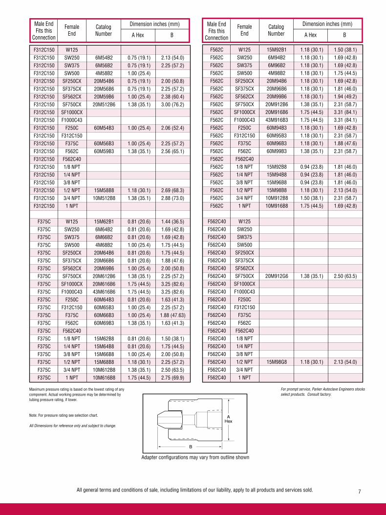
Female End
Male End Fits this
Connection
CatalogNumber
Dimension inches (mm)
A Hex BFemale
End
Male End Fits this
Connection
CatalogNumber
Dimension inches (mm)
A Hex B
B
AHex
All general terms and conditions of sale, including limitations of our liability, apply to all products and services sold. 7
For prompt service, Parker Autoclave Engineers stocks select products. Consult factory.
Maximum pressure rating is based on the lowest rating of any component. Actual working pressure may be determined by tubing pressure rating, if lower.
Note: For pressure rating see selection chart.
All Dimensions for reference only and subject to change.
Adapter configurations may vary from outline shown
F312C150 W125 F312C150 SW250 6M54B2 0.75 (19.1) 2.13 (54.0) F312C150 SW375 6M56B2 0.75 (19.1) 2.25 (57.2) F312C150 SW500 4M58B2 1.00 (25.4) F312C150 SF250CX 20M54B6 0.75 (19.1) 2.00 (50.8) F312C150 SF375CX 20M56B6 0.75 (19.1) 2.25 (57.2) F312C150 SF562CX 20M59B6 1.00 (25.4) 2.38 (60.4) F312C150 SF750CX 20M512B6 1.38 (35.1) 3.00 (76.2) F312C150 SF1000CX F312C150 F1000C43 F312C150 F250C 60M54B3 1.00 (25.4) 2.06 (52.4) F312C150 F312C150 F312C150 F375C 60M56B3 1.00 (25.4) 2.25 (57.2) F312C150 F562C 60M59B3 1.38 (35.1) 2.56 (65.1) F312C150 F562C40 F312C150 1/8 NPT F312C150 1/4 NPT F312C150 3/8 NPT F312C150 1/2 NPT 15M58B8 1.18 (30.1) 2.69 (68.3) F312C150 3/4 NPT 10M512B8 1.38 (35.1) 2.88 (73.0) F312C150 1 NPT
F375C W125 15M62B1 0.81 (20.6) 1.44 (36.5) F375C SW250 6M64B2 0.81 (20.6) 1.69 (42.8) F375C SW375 6M66B2 0.81 (20.6) 1.69 (42.8) F375C SW500 4M68B2 1.00 (25.4) 1.75 (44.5) F375C SF250CX 20M64B6 0.81 (20.6) 1.75 (44.5) F375C SF375CX 20M66B6 0.81 (20.6) 1.88 (47.6) F375C SF562CX 20M69B6 1.00 (25.4) 2.00 (50.8) F375C SF750CX 20M612B6 1.38 (35.1) 2.25 (57.2) F375C SF1000CX 20M616B6 1.75 (44.5) 3.25 (82.6) F375C F1000C43 43M616B6 1.75 (44.5) 3.25 (82.6) F375C F250C 60M64B3 0.81 (20.6) 1.63 (41.3) F375C F312C150 60M65B3 1.00 (25.4) 2.25 (57.2) F375C F375C 60M66B3 1.00 (25.4) 1.88 (47.63) F375C F562C 60M69B3 1.38 (35.1) 1.63 (41.3) F375C F562C40 F375C 1/8 NPT 15M62B8 0.81 (20.6) 1.50 (38.1) F375C 1/4 NPT 15M64B8 0.81 (20.6) 1.75 (44.5) F375C 3/8 NPT 15M66B8 1.00 (25.4) 2.00 (50.8) F375C 1/2 NPT 15M68B8 1.18 (30.1) 2.25 (57.2) F375C 3/4 NPT 10M612B8 1.38 (35.1) 2.50 (63.5) F375C 1 NPT 10M616B8 1.75 (44.5) 2.75 (69.9)
F562C W125 15M92B1 1.18 (30.1) 1.50 (38.1) F562C SW250 6M94B2 1.18 (30.1) 1.69 (42.8) F562C SW375 6M96B2 1.18 (30.1) 1.69 (42.8) F562C SW500 4M98B2 1.18 (30.1) 1.75 (44.5) F562C SF250CX 20M94B6 1.18 (30.1) 1.69 (42.8) F562C SF375CX 20M96B6 1.18 (30.1) 1.81 (46.0) F562C SF562CX 20M99B6 1.18 (30.1) 1.94 (49.2) F562C SF750CX 20M912B6 1.38 (35.1) 2.31 (58.7) F562C SF1000CX 20M916B6 1.75 (44.5) 3.31 (84.1) F562C F1000C43 43M916B3 1.75 (44.5) 3.31 (84.1) F562C F250C 60M94B3 1.18 (30.1) 1.69 (42.8) F562C F312C150 60M95B3 1.18 (30.1) 2.31 (58.7) F562C F375C 60M96B3 1.18 (30.1) 1.88 (47.6) F562C F562C 60M99B3 1.38 (35.1) 2.31 (58.7) F562C F562C40 F562C 1/8 NPT 15M92B8 0.94 (23.8) 1.81 (46.0) F562C 1/4 NPT 15M94B8 0.94 (23.8) 1.81 (46.0) F562C 3/8 NPT 15M96B8 0.94 (23.8) 1.81 (46.0) F562C 1/2 NPT 15M98B8 1.18 (30.1) 2.13 (54.0) F562C 3/4 NPT 10M912B8 1.50 (38.1) 2.31 (58.7) F562C 1 NPT 10M916B8 1.75 (44.5) 1.69 (42.8)
F562C40 W125 F562C40 SW250 F562C40 SW375 F562C40 SW500 F562C40 SF250CX F562C40 SF375CX F562C40 SF562CX F562C40 SF750CX 20M912G6 1.38 (35.1) 2.50 (63.5) F562C40 SF1000CX F562C40 F1000C43 F562C40 F250C F562C40 F312C150 F562C40 F375C F562C40 F562C F562C40 F562C40 F562C40 1/8 NPT F562C40 1/4 NPT F562C40 3/8 NPT F562C40 1/2 NPT 15M98G8 1.18 (30.1) 2.13 (54.0) F562C40 3/4 NPT F562C40 1 NPT
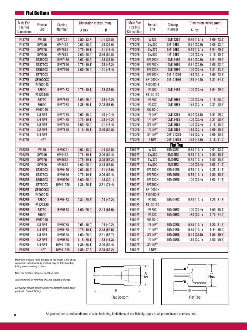
Flat Bottom
Female End
Male End Fits this
Connection
CatalogNumber
Dimension inches (mm)
A Hex BFemale
End
Male End Fits this
Connection
CatalogNumber
Dimension inches (mm)
A Hex B
Flat Top
B
AHex
All general terms and conditions of sale, including limitations of our liability, apply to all products and services sold.8
Flat Bottom Flat Top
Maximum pressure rating is based on the lowest rating of any component. Actual working pressure may be determined by tubing pressure rating, if lower.
Note: For pressure rating see selection chart.
All Dimensions for reference only and subject to change.
For prompt service, Parker Autoclave Engineers stocks select products. Consult factory. B
AHex
F437FB W125 15M72E1 0.50 (12.7) 1.41 (35.8) F437FB SW250 6M74E2 0.63 (15.9) 1.53 (38.9) F437FB SW375 6M76E2 0.75 (19.1) 1.91 (48.4) F437FB SW500 4M78E2 1.00 (25.4) 2.16 (54.8) F437FB SF250CX 15M74E6 0.63 (15.9) 1.53 (38.9) F437FB SF375CX 15M76E6 0.75 (19.1) 1.78 (45.2) F437FB SF562CX 15M79E6 1.00 (25.4) 1.91 (48.4) F437FB SF750CX F437FB SF1000CX F437FB F1000C43 F437FB F250C 15M74E3 0.75 (19.1) 1.53 (38.9) F437FB F312C150 F437FB F375C 15M76E3 1.00 (25.4) 1.78 (45.2) F437FB F562C 15M79E3 1.38 (35.1) 2.03 (51.6) F437FB F562C40 F437FB 1/8 NPT 10M72E8 0.63 (15.9) 1.59 (40.4) F437FB 1/4 NPT 10M74E8 0.75 (19.1) 1.78 (45.2) F437FB 3/8 NPT 10M76E8 1.00 (25.4) 1.91 (48.4) F437FB 1/2 NPT 10M78E8 1.18 (30.1) 2.16 (54.8) F437FB 3/4 NPT F437FB 1 NPT
F562FB W125 15M92E1 0.63 (15.9) 1.44 (36.5) F562FB SW250 6M94E2 0.75 (19.1) 2.06 (52.4) F562FB SW375 6M96E2 0.75 (19.1) 2.25 (57.2) F562FB SW500 4M98E2 1.00 (25.4) 2.18 (55.5) F562FB SF250CX 15M94E6 0.63 (15.9) 1.81 (46.0) F562FB SF375CX 15M96E6 0.75 (19.1) 2.06 (52.4) F562FB SF562CX 15M99E6 1.00 (25.4) 1.18 (30.1) F562FB SF750CX 15M912E6 1.38 (35.1) 2.81 (71.4) F562FB SF1000CX F562FB F1000C43 F562FB F250C 15M94E3 0.81 (20.6) 1.94 (49.2) F562FB F312C150 F562FB F375C 15M96E3 1.00 (25.4) 2.44 (61.9) F562FB F562C F562FB F562C40 F562FB 1/8 NPT 10M92E8 0.63 (15.9) 1.94 (49.2) F562FB 1/4 NPT 10M94E8 0.75 (19.1) 2.18 (55.5) F562FB 3/8 NPT 10M96E8 1.00 (25.4) 2.31 (58.7) F562FB 1/2 NPT 10M98E8 1.18 (30.1) 1.63 (41.3) F562FB 3/4 NPT 10M912E8 1.38 (35.1) 2.06 (52.4) F562FB 1 NPT 10M916E8 1.88 (47.6) 2.25 (57.2)
F750FB W125 15M122E1 0.75 (19.1) 1.69 (42.8) F750FB SW250 6M124E2 0.81 (20.6) 2.06 (52.4) F750FB SW375 6M126E2 0.75 (19.1) 1.94 (49.2) F750FB SW500 4M128E2 1.00 (25.4) 2.18 (55.5) F750FB SF250CX 15M124E6 0.81 (20.6) 1.94 (49.2) F750FB SF375CX 15M126E6 0.81 (20.6) 2.06 (52.4) F750FB SF562CX 15M129E6 1.00 (25.4) 1.31 (33.3) F750FB SF750CX 15M1212E6 1.38 (35.1) 1.69 (42.8) F750FB SF1000CX 15M1216E6 1.75 (44.5) 3.31 (84.1) F750FB F1000C43 F750FB F250C 15M124E3 1.00 (25.4) 1.94 (49.2) F750FB F312C150 F750FB F375C 15M126E3 1.00 (25.4) 2.18 (55.5) F750FB F562C 15M129E3 1.38 (35.1) 2.31 (58.7) F750FB F562C40 F750FB 1/8 NPT 10M122E8 0.94 (23.8) 1.81 (46.0) F750FB 1/4 NPT 10M124E8 1.00 (25.4) 2.31 (58.7) F750FB 3/8 NPT 10M126E8 1.00 (25.4) 2.18 (55.5) F750FB 1/2 NPT 10M128E8 1.18 (30.1) 2.69 (68.3) F750FB 3/4 NPT 10M1212E8 1.38 (35.1) 2.69 (68.3) F750FB 1 NPT 10M1216E8 1.88 (47.6) 3.18 (81.0)
F562FT W125 15M92R1 0.75 (19.1) 0.94 (23.9) F562FT SW250 6M94R2 0.75 (19.1) 1.50 (38.1) F562FT SW375 6M96R2 0.75 (19.1) 1.50 (38.1) F562FT SW500 4M98R2 1.00 (25.4) 1.63 (41.3) F562FT SF250CX 15M94R6 0.75 (19.1) 1.25 (31.8) F562FT SF375CX 15M96R6 0.75 (19.1) 1.50 (38.1) F562FT SF562CX 15M99R6 1.00 (25.4) 1.63 (41.3) F562FT SF750CX F562FT SF1000CX F562FT F1000C43 F562FT F250C 15M94R3 0.75 (19.1) 1.25 (31.8) F562FT F312C150 F562FT F375C 15M96R3 1.00 (25.4) 1.50 (38.1) F562FT F562C 15M99R3 1.38 (35.1) 1.75 (44.5) F562FT F562C40 F562FT 1/8 NPT 10M92R8 0.75 (19.1) 1.25 (31.8) F562FT 1/4 NPT 10M94R8 0.75 (19.1) 1.44 (36.5) F562FT 3/8 NPT 10M96R8 0.94 (23.8) 1.56 (39.7) F562FT 1/2 NPT 10M98R8 1.18 (30.1) 2.00 (50.8) F562FT 3/4 NPT F562FT 1 NPT
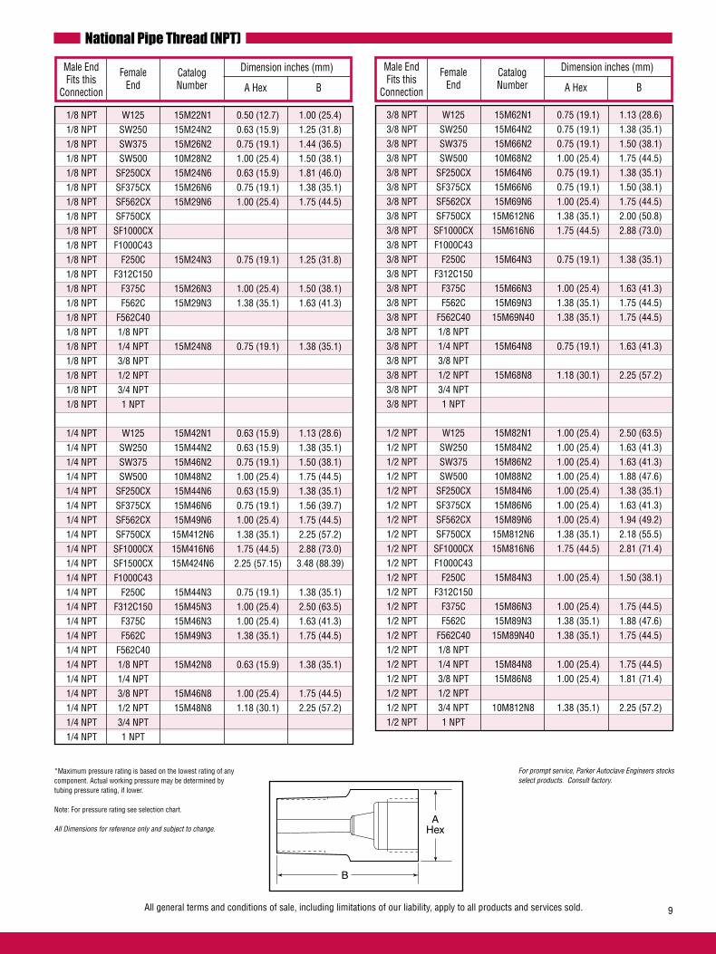
National Pipe Thread (NPT)
Female End
Male End Fits this
Connection
CatalogNumber
Dimension inches (mm)
A Hex BFemale
End
Male End Fits this
Connection
CatalogNumber
Dimension inches (mm)
A Hex B
All general terms and conditions of sale, including limitations of our liability, apply to all products and services sold. 9
For prompt service, Parker Autoclave Engineers stocks select products. Consult factory.
*Maximum pressure rating is based on the lowest rating of any component. Actual working pressure may be determined by tubing pressure rating, if lower.
Note: For pressure rating see selection chart.
All Dimensions for reference only and subject to change.
1/8 NPT W125 15M22N1 0.50 (12.7) 1.00 (25.4) 1/8 NPT SW250 15M24N2 0.63 (15.9) 1.25 (31.8) 1/8 NPT SW375 15M26N2 0.75 (19.1) 1.44 (36.5) 1/8 NPT SW500 10M28N2 1.00 (25.4) 1.50 (38.1) 1/8 NPT SF250CX 15M24N6 0.63 (15.9) 1.81 (46.0) 1/8 NPT SF375CX 15M26N6 0.75 (19.1) 1.38 (35.1) 1/8 NPT SF562CX 15M29N6 1.00 (25.4) 1.75 (44.5) 1/8 NPT SF750CX 1/8 NPT SF1000CX 1/8 NPT F1000C43 1/8 NPT F250C 15M24N3 0.75 (19.1) 1.25 (31.8) 1/8 NPT F312C150 1/8 NPT F375C 15M26N3 1.00 (25.4) 1.50 (38.1) 1/8 NPT F562C 15M29N3 1.38 (35.1) 1.63 (41.3) 1/8 NPT F562C40 1/8 NPT 1/8 NPT 1/8 NPT 1/4 NPT 15M24N8 0.75 (19.1) 1.38 (35.1) 1/8 NPT 3/8 NPT 1/8 NPT 1/2 NPT 1/8 NPT 3/4 NPT 1/8 NPT 1 NPT
1/4 NPT W125 15M42N1 0.63 (15.9) 1.13 (28.6) 1/4 NPT SW250 15M44N2 0.63 (15.9) 1.38 (35.1) 1/4 NPT SW375 15M46N2 0.75 (19.1) 1.50 (38.1) 1/4 NPT SW500 10M48N2 1.00 (25.4) 1.75 (44.5) 1/4 NPT SF250CX 15M44N6 0.63 (15.9) 1.38 (35.1) 1/4 NPT SF375CX 15M46N6 0.75 (19.1) 1.56 (39.7) 1/4 NPT SF562CX 15M49N6 1.00 (25.4) 1.75 (44.5) 1/4 NPT SF750CX 15M412N6 1.38 (35.1) 2.25 (57.2) 1/4 NPT SF1000CX 15M416N6 1.75 (44.5) 2.88 (73.0) 1/4 NPT SF1500CX 15M424N6 2.25 (57.15) 3.48 (88.39) 1/4 NPT F1000C43 1/4 NPT F250C 15M44N3 0.75 (19.1) 1.38 (35.1) 1/4 NPT F312C150 15M45N3 1.00 (25.4) 2.50 (63.5) 1/4 NPT F375C 15M46N3 1.00 (25.4) 1.63 (41.3) 1/4 NPT F562C 15M49N3 1.38 (35.1) 1.75 (44.5) 1/4 NPT F562C40 1/4 NPT 1/8 NPT 15M42N8 0.63 (15.9) 1.38 (35.1) 1/4 NPT 1/4 NPT 1/4 NPT 3/8 NPT 15M46N8 1.00 (25.4) 1.75 (44.5) 1/4 NPT 1/2 NPT 15M48N8 1.18 (30.1) 2.25 (57.2) 1/4 NPT 3/4 NPT 1/4 NPT 1 NPT
3/8 NPT W125 15M62N1 0.75 (19.1) 1.13 (28.6) 3/8 NPT SW250 15M64N2 0.75 (19.1) 1.38 (35.1) 3/8 NPT SW375 15M66N2 0.75 (19.1) 1.50 (38.1) 3/8 NPT SW500 10M68N2 1.00 (25.4) 1.75 (44.5) 3/8 NPT SF250CX 15M64N6 0.75 (19.1) 1.38 (35.1) 3/8 NPT SF375CX 15M66N6 0.75 (19.1) 1.50 (38.1) 3/8 NPT SF562CX 15M69N6 1.00 (25.4) 1.75 (44.5) 3/8 NPT SF750CX 15M612N6 1.38 (35.1) 2.00 (50.8) 3/8 NPT SF1000CX 15M616N6 1.75 (44.5) 2.88 (73.0) 3/8 NPT F1000C43 3/8 NPT F250C 15M64N3 0.75 (19.1) 1.38 (35.1) 3/8 NPT F312C150 3/8 NPT F375C 15M66N3 1.00 (25.4) 1.63 (41.3) 3/8 NPT F562C 15M69N3 1.38 (35.1) 1.75 (44.5) 3/8 NPT F562C40 15M69N40 1.38 (35.1) 1.75 (44.5) 3/8 NPT 1/8 NPT 3/8 NPT 1/4 NPT 15M64N8 0.75 (19.1) 1.63 (41.3) 3/8 NPT 3/8 NPT 3/8 NPT 1/2 NPT 15M68N8 1.18 (30.1) 2.25 (57.2) 3/8 NPT 3/4 NPT 3/8 NPT 1 NPT
1/2 NPT W125 15M82N1 1.00 (25.4) 2.50 (63.5) 1/2 NPT SW250 15M84N2 1.00 (25.4) 1.63 (41.3) 1/2 NPT SW375 15M86N2 1.00 (25.4) 1.63 (41.3) 1/2 NPT SW500 10M88N2 1.00 (25.4) 1.88 (47.6) 1/2 NPT SF250CX 15M84N6 1.00 (25.4) 1.38 (35.1) 1/2 NPT SF375CX 15M86N6 1.00 (25.4) 1.63 (41.3) 1/2 NPT SF562CX 15M89N6 1.00 (25.4) 1.94 (49.2) 1/2 NPT SF750CX 15M812N6 1.38 (35.1) 2.18 (55.5) 1/2 NPT SF1000CX 15M816N6 1.75 (44.5) 2.81 (71.4) 1/2 NPT F1000C43 1/2 NPT F250C 15M84N3 1.00 (25.4) 1.50 (38.1) 1/2 NPT F312C150 1/2 NPT F375C 15M86N3 1.00 (25.4) 1.75 (44.5) 1/2 NPT F562C 15M89N3 1.38 (35.1) 1.88 (47.6) 1/2 NPT F562C40 15M89N40 1.38 (35.1) 1.75 (44.5) 1/2 NPT 1/8 NPT 1/2 NPT 1/4 NPT 15M84N8 1.00 (25.4) 1.75 (44.5) 1/2 NPT 3/8 NPT 15M86N8 1.00 (25.4) 1.81 (71.4) 1/2 NPT 1/2 NPT 1/2 NPT 3/4 NPT 10M812N8 1.38 (35.1) 2.25 (57.2) 1/2 NPT 1 NPT
B
AHex
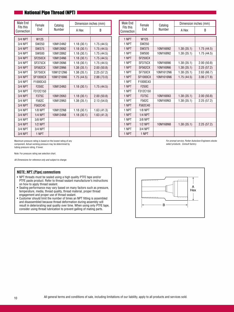
Female End
Male End Fits this
Connection
CatalogNumber
Dimension inches (mm)
A Hex BFemale
End
Male End Fits this
Connection
CatalogNumber
Dimension inches (mm)
A Hex B
B
AHex
All general terms and conditions of sale, including limitations of our liability, apply to all products and services sold.10
National Pipe Thread (NPT)
For prompt service, Parker Autoclave Engineers stocks select products. Consult factory.
Maximum pressure rating is based on the lowest rating of any component. Actual working pressure may be determined by tubing pressure rating, if lower.
Note: For pressure rating see selection chart.
All Dimensions for reference only and subject to change.
3/4 NPT W125 3/4 NPT SW250 10M124N2 1.18 (30.1) 1.75 (44.5) 3/4 NPT SW375 10M126N2 1.18 (30.1) 1.75 (44.5) 3/4 NPT SW500 10M128N2 1.18 (30.1) 1.75 (44.5) 3/4 NPT SF250CX 10M124N6 1.18 (30.1) 1.75 (44.5) 3/4 NPT SF375CX 10M126N6 1.18 (30.1) 1.75 (44.5) 3/4 NPT SF562CX 10M129N6 1.38 (35.1) 2.00 (50.8) 3/4 NPT SF750CX 10M1212N6 1.38 (35.1) 2.25 (57.2) 3/4 NPT SF1000CX 10M1216N6 1.75 (44.5) 2.88 (73.0) 3/4 NPT F1000C43 3/4 NPT F250C 10M124N3 1.18 (30.1) 1.75 (44.5) 3/4 NPT F312C150 3/4 NPT F375C 10M126N3 1.18 (30.1) 2.00 (50.8) 3/4 NPT F562C 10M129N3 1.38 (35.1) 2.13 (54.0) 3/4 NPT F562C40 3/4 NPT 1/8 NPT 10M122N8 1.18 (30.1) 1.63 (41.3) 3/4 NPT 1/4 NPT 10M124N8 1.18 (30.1) 1.63 (41.3) 3/4 NPT 3/8 NPT 3/4 NPT 1/2 NPT 3/4 NPT 3/4 NPT 3/4 NPT 1 NPT
1 NPT W125 1 NPT SW250 1 NPT SW375 10M166N2 1.38 (35.1) 1.75 (44.5) 1 NPT SW500 10M168N2 1.38 (35.1) 1.75 (44.5) 1 NPT SF250CX 1 NPT SF375CX 10M166N6 1.38 (35.1) 2.00 (50.8) 1 NPT SF562CX 10M169N6 1.38 (35.1) 2.25 (57.2) 1 NPT SF750CX 10M1612N6 1.38 (35.1) 2.63 (66.7) 1 NPT SF1000CX 10M1616N6 1.75 (44.5) 3.06 (77.8) 1 NPT F1000C43 1 NPT F250C 1 NPT F312C150 1 NPT F375C 10M166N3 1.38 (35.1) 2.00 (50.8) 1 NPT F562C 10M169N3 1.38 (35.1) 2.25 (57.2) 1 NPT F562C40 1 NPT 1/8 NPT 1 NPT 1/4 NPT 1 NPT 3/8 NPT 1 NPT 1/2 NPT 10M168N8 1.38 (35.1) 2.25 (57.2) 1 NPT 3/4 NPT 1 NPT 1 NPT
NOTE: NPT (Pipe) connections• NPT threads must be sealed using a high quality PTFE tape and/or PTFE paste product. Refer to thread sealant manufacturer’s instructions on how to apply thread sealant.• Sealing performance may vary based on many factors such as pressure, temperature, media, thread quality, thread material, proper thread engagement and proper use of thread sealant.• Customer should limit the number of times an NPT fitting is assembled and disassembled because thread deformation during assembly will result in deteriorating seal quality over time. When using only PTFE tape, consider using thread lubrication to prevent galling of mating parts.

Adapters/Couplings - Couplings
The couplings shown here permit the joining of any combina-tion of standard size tubing or tubing and standard pipe with female-to-female couplings. Other couplings available on special order. Pressure Rating - The pressure rating of Parker Autoclave Engineers couplings is based on the lower rated connection used.
Tube 1/8 1/4 3/8 1/2** 1/4 3/8 9/16 3/4 1 1 1/4 3/8 9/16 9/16 5/16 Outside Connector Pressure W SW SW SW SF SF SF SF SF F F F F F F in (mm) Type psi 125 250 375 500 250 375 562 750 1000 1000 250 375 562 562 312 (bar)* CX CX CX CX CX C43 C C C C40 C150
1/8 W125 15,000 15F 6F 6F 4F 15F 15F 15F 15F 15F 15F 15F (3.18) (1034) 2211 2412 2612 2812 2416 2616 2916 21616 2413 2613 2913
1/4 SW250 15,000 6F 6F 4F 6F 6F 6F 6F 6F 6F (6.35) (1034) 4422 4622 4822 4426 4626 4926 4423 4623 4923
3/8 SW375 15,000 6F 4F 6F 6F 6F 6F 6F 6F 6F 6F (9.52) (1034) 6622 6822 6426 6626 6926 61226 61626 6423 6623 6923
1/2 SW500 10,000 4F 4F 4F 4F 4F 4F 4F 4F 4F (12.70) (690) 8822 8426 8626 8926 81226 81626 8423 8623 8923
1/4 SF250 20,000 20FX 20F 20F 20F 20F 20F 20F 20F 20F 20F (6.35) CX (1379) 4466 4666 4966 41266 41666 41663 4463 4663 4963 4563
3/8 SF375 20,000 20FX 20F 20F 20F 20F 20F 20F 20F 20F (9.52) CX (1379) 6666 6966 61266 61666 61663 6463 6663 6963 6563
9/16 SF562 20,000 20FX 20F 20F 20F 20F 20F 20F (14.27) CX (1379) 9966 91266 91666 9463 9663 9963 9563
3/4 SF750 20,000 20FX 20F 20F 20F 20F 20F (19.05) CX (1379) 12 121666 12463 12663 12963 12563
1 SF1000 20,000 20FX 20F 20F 20F 20F (25.40) CX (1379) 16 16463 16663 16963 16563
1 F1000 43,000 43F (25.40) C43 (2965) 16
1/4 F250 60,000 43F 60F 60F 60F 60F (6.35) C (4137) 41633 4433 4633 4933 4533
3/8 F375 60,000 43F 60F 60F 60F (9.52) C (4137) 61633 6633 6933 6533
9/16 F562 60,000 43F 60F 60F (14.27) C (4137) 91633 9933 9533
9/16 F562 40,000 40F (14.27) C40 (2760) 9933 5/16 F312 15,000 150F (7.92) C150 (1034) 5533 1/8 NPT 15,000 15F 15F 15F 10F 15F 15F 15F 15F 15F 15F 15F 15F (3.18) (1034) 2281 2482 2682 2882 2486 2686 2986 21286 2483 2683 2983 2583
1/4 NPT 15,000 15F 15F 15F 10F 15F 15F 15F 15F 15F 15F 15F 15F 15F (6.35) (1034) 4281 4482 4682 4882 4486 4686 4986 41286 41686 4483 4683 4983 4583
3/8 NPT 15,000 15F 15F 15F 10F 15F 15F 15F 15F 15F 15F 15F 15F 15F (9.52) (1034) 6281 6482 6682 6882 6486 6686 6986 61286 61686 6483 6683 6983 6583
1/2 NPT 15,000 15F 15F 15F 10F 15F 15F 15F 15F 15F 15F 15F 15F 15F (12.70) (1034) 8281 8482 8682 8882 8486 8686 8986 81286 81686 8483 8683 8983 8583
3/4 NPT 10,000 10F 10F 10F 10F 10F 10F (19.05) (1034) 12882 12686 12986 121286 121686 12983 1 NPT 10,000 10F 10F 10F 10F (25.40) (1034) 16986 161686 16483 16983
How to use the Ordering Chart below: 1. Locate “A” connection in the vertical column.2. Locate the desired “B” connection across the top of the chart.3. The catalog number of the required coupling is located at the intersection of the two columns.
“A”Connection
“B” ConnectionSpeedBite Medium Pressure High Pressure
Spee
dBite
Med
ium
Pre
ssur
eHi
gh P
ress
ure
Natio
nal P
ipe
Thre
ad (N
PT)
*Maximum pressure rating is based on the lowest rating of any component. Actual working pressure may be determined by tubing pressure rating, if lower.**1/2 low pressure rated to 10,000 psi.
All dimensions for reference only and subject to change.For prompt service, Parker Autoclave Engineers stocks select products. Consult your local representative.CAUTION: See appropriate pressure section in reference to proper selection of tubing.
All general terms and conditions of sale, including limitations of our liability, apply to all products and services sold. 11
"A"CONNECTION
FEMALE
"B"CONNECTION
FEMALE
Note: Special material couplings may be supplied with four flats in place of standard hex.

All general terms and conditions of sale, including limitations of our liability, apply to all products and services sold.
Coupling Dimensions - Speedbite
Connection “B”
Connection “A”
CatalogNumber
Dimension inches (mm)
A Hex B
W125 W125 15F2211 0.50 (12.7) 1.25 (31.7) W125 SW250 6F2412 0.63 (15.9) 1.44 (36.6) W125 SW375 6F2612 0.75 (19.1) 1.50 (38.1) W125 SW500 4F2812 1.00 (25.4) 1.63 (41.4) W125 SF250CX 15F2416 0.63 (15.9) 1.38 (35.1) W125 SF375CX 15F2616 0.75 (19.1) 1.50 (38.1) W125 SF562CX 15F2916 1.00 (25.4) 1.75 (44.5) W125 SF1000CX 15F21616 1.75 (44.5) 2.75 (69.9) W125 F250C 15F2413 0.75 (19.1) 1.25 (31.7) W125 F375C 15F2613 1.00 (25.4) 1.50 (38.1) W125 F562C 15F2913 1.38 (35.1) 1.75 (44.5)
SW250 SW250 6F4422 0.63 (15.9) 1.63 (41.4) SW250 SW375 6F4622 0.75 (19.1) 1.69 (42.9) SW250 SW500 4F4822 1.00 (25.4) 1.88 (47.8) SW250 SF250CX 6F4426 0.63 (15.9) 1.63 (41.4) SW250 SF375CX 6F4626 0.75 (19.1) 1.75 (44.5) SW250 SF562CX 6F4926 1.00 (25.4) 2.00 (50.8) SW250 F250C 6F4423 0.75 (19.1) 1.50 (38.1) SW250 F375C 6F4623 1.00 (25.4) 1.69 (42.9) SW250 F562C 6F4923 1.38 (35.1) 2.06 (52.3)
Connection “B”
Connection “A”
CatalogNumber
Dimension inches (mm)
A Hex B
SW375 SW375 6F6622 0.75 (19.1) 1.75 (44.5) SW375 SW500 4F6822 1.00 (25.4) 1.88 (47.8) SW375 SF250CX 6F6426 0.75 (19.1) 0.88 (22.2) SW375 SF375CX 6F6626 0.75 (19.1) 1.75 (44.5) SW375 SF562CX 6F6926 1.00 (25.4) 2.00 (50.8) SW375 SF750CX 6F61226 1.38 (35.1) 2.25 (57.2) SW375 SF1000CX 6F61626 1.75 (44.5) 3.00 (76.2) SW375 F250C 6F6423 0.75 (19.1) 1.63 (41.4) SW375 F375C 6F6623 1.00 (25.4) 1.81 (46.0) SW375 F562C 6F6923 1.38 (35.1) 2.00 (50.8)
SW500 SW500 4F8822 1.00 (25.4) 2.00 (50.8) SW500 SF250CX 4F8426 1.00 (25.4) 1.63 (41.4) SW500 SF375CX 4F8626 1.00 (25.4) 1.88 (47.8) SW500 SF562CX 4F8926 1.00 (25.4) 2.00 (50.8) SW500 SF750CX 4F81226 1.38 (35.1) 2.25 (57.2) SW500 SF1000CX 4F81626 1.75 (44.5) 3.00 (76.2) SW500 F250C 4F8423 1.00 (25.4) 1.69 (42.9) SW500 F375C 4F8623 1.00 (25.4) 1.88 (47.8) SW500 F562C 4F8923 1.38 (35.1) 2.06 (52.3)
Maximum pressure rating is based on the lowest rating of any component. Actual working pressure may be determined by tubing pressure rating, if lower.Note: For pressure rating see selection chart.
All dimensions for reference only and subject to change.For prompt service, Parker Autoclave Engineers stocks select products. Consult your local representative.
12
Coupling Dimensions - Medium Pressure
Connection “B”
Connection “A”
CatalogNumber
Dimension inches (mm)
A Hex BConnection
“B”Connection
“A”CatalogNumber
Dimension inches (mm)
A Hex B
SF750CX SF750CX 20FX12 1.38 (35.1) 2.50 (63.5) SF750CX SF1000CX 20F121666 1.75 (44.5) 3.00 (76.2) SF750CX F250C 20F12463 1.38 (35.1) 2.50 (63.5) SF750CX F375C 20F12663 1.38 (35.1) 2.38 (60.33) SF750CX F562C 20F12963 1.38 (35.1) 2.75 (69.9) SF750CX F312C150 20F12563 1.38 (35.1) 2.75 (69.9)
SF1000CX SF1000CX 20FX16 1.75 (44.5) 3.50 (88.9) SF1000CX F250C 20F16463 1.75 (44.5) 2.75 (69.9) SF1000CX F375C 20F16663 1.75 (44.5) 2.88 (73.0) SF1000CX F562C 20F16963 1.75 (44.5) 3.25 (82.6) SF1000CX F312C150 20F16563 1.75 (44.5) 3.25 (82.6)
SF250CX SF250CX 20FX4466 0.63 (15.9) 1.63 (41.4) SF250CX SF375CX 20F4666 0.75 (19.1) 1.75 (44.5) SF250CX SF562CX 20F4966 1.00 (25.4) 2.00 (50.8) SF250CX SF750CX 20F41266 1.38 (35.1) 2.25 (57.2) SF250CX SF1000CX 20F41666 1.75 (44.5) 2.75 (69.9) SF250CX F250C 20F4463 0.75 (19.1) 1.38 (35.1) SF250CX F375C 20F4663 1.00 (25.4) 1.63 (41.4) SF250CX F562C 20F4963 1.38 (35.1) 1.88 (47.8) SF250CX F312C150 20F4563 1.00 (25.4) 2.13 (54.1) SF250CX F1000C43 43F41663 1.75 (44.5) 2.75 (69.9) SF375CX SF375CX 20FX6666 0.75 (19.1) 1.75 (44.5) SF375CX SF562CX 20F6966 1.00 (25.4) 2.00 (50.8) SF375CX SF750CX 20F61266 1.38 (35.1) 2.25 (57.2) SF375CX SF1000CX 20F61666 1.75 (44.5) 2.88 (73.0) SF375CX F250C 20F6463 0.75 (19.1) 1.63 (41.4) SF375CX F375C 20F6663 1.00 (25.4) 2.00 (50.8) SF375CX F562C 20F6963 1.38 (35.1) 2.00 (50.8) SF375CX F312C150C 20F6563 1.00 (25.4) 2.25 (57.2) SF375CX F1000C43 43F61663 1.75 (44.5) 2.88 (73.0) SF562CX SF562CX 20FX9966 1.00 (25.4) 2.13 (54.1) SF562CX SF750CX 20F91266 1.38 (35.1) 2.50 (63.5) SF562CX SF1000CX 20F91666 1.75 (44.5) 3.00 (76.2) SF562CX F250C 20F9463 1.00 (25.4) 2.00 (50.8) SF562CX F375C 20F9663 1.00 (25.4) 2.00 (50.8) SF562CX F562C 20F9963 1.38 (35.1) 2.25 (57.2) SF562CX F312C150C 20F9563 1.00 (25.4) 2.50 (63.5)
AHEX
B

Coupling Dimensions - National Pipe Thread (NPT)
All general terms and conditions of sale, including limitations of our liability, apply to all products and services sold.
Coupling Dimensions - High Pressure
Connection “B”
Connection “A”
CatalogNumber A Hex B
F250C F250C 60F4433 0.75 (19.1) 1.38 (35.1) F250C F375C 60F4633 1.00 (25.4) 1.63 (41.4) F250C F562C 60F4933 1.38 (35.1) 1.75 (44.5) F250C F312C150 60F4533 1.00 (25.4) 2.00 (50.8) F250C F1000C43 43F41633 1.75 (44.5) 2.75 (69.9) F375C F375C 60F6633 1.00 (25.4) 1.75 (44.5) F375C F562C 60F6933 1.38 (35.1) 2.00 (50.8) F375C F312C150 60F6533 1.00 (25.4) 2.25 (57.2) F375C F1000C43 43F61633 1.75 (44.5) 2.88 (73.0) F562C F562C 60F9933 1.38 (35.1) 2.19 (55.6) F562C40 F562C40 40F9933 1.38 (35.1) 2.19 (55.6) F562C F312C150 60F9533 1.19 (30.1) 2.63 (66.7) F562C SF1000C43 43F91633 1.75 (44.5) 3.75 (82.6) F312C150 F312C150 150F5533 1.38 (35.1) 2.50 (63.5) F1000C43 F1000C43 43F16 1.75 (44.5) 3.50 (88.9)
Connection “B”
Connection “A”
CatalogNumber
Dimension inches (mm)
A Hex BConnection
“B”Connection
“A”CatalogNumber
Dimension inches (mm)
A Hex B
1/8 NPT W125 15F2281 0.63 (15.9) 1.38 (35.1) 1/8 NPT SW250 15F2482 0.63 (15.9) 1.50 (38.1) 1/8 NPT SW375 15F2682 0.75 (19.1) 1.63 (41.4) 1/8 NPT SW500 10F2882 1.00 (25.4) 1.50 (38.1) 1/8 NPT SF250CX 15F2486 0.63 (15.9) 1.38 (35.1) 1/8 NPT SF375CX 15F2686 0.75 (19.1) 1.50 (38.1) 1/8 NPT SF562CX 15F2986 1.00 (25.4) 1.63 (41.4) 1/8 NPT SF750CX 15F21286 1.38 (35.1) 1.75 (44.5) 1/8 NPT F250C 15F2483 0.75 (19.1) 1.38 (35.1) 1/8 NPT F375C 15F2683 1.00 (25.4) 1.63 (41.4) 1/8 NPT F562C 15F2983 1.38 (35.1) 1.82 (46.2) 1/8 NPT F312C150 15F2583 1.00 (25.4) 2.13 (54.1)
1/4 NPT W125 15F4281 0.75 (19.1) 1.50 (38.1) 1/4 NPT SW250 15F4482 0.75 (19.1) 1.63 (41.4) 1/4 NPT SW375 15F4682 0.75 (19.1) 1.75 (44.5) 1/4 NPT SW500 10F4882 1.00 (25.4) 2.00 (50.8) 1/4 NPT SF250CX 15F4486 0.75 (19.1) 1.63 (41.4) 1/4 NPT SF375CX 15F4686 0.75 (19.1) 1.75 (44.5) 1/4 NPT SF562CX 15F4986 1.00 (25.4) 2.00 (50.8) 1/4 NPT SF750CX 15F41286 1.38 (35.1) 1.75 (44.5) 1/4 NPT SF1000CX 15F41686 1.38 (35.1) 2.38 (60.33) 1/4 NPT F250C 15F4483 0.75 (19.1) 1.63 (41.4) 1/4 NPT F375C 15F4683 1.00 (25.4) 1.88 (47.8) 1/4 NPT F562C 15F4983 1.38 (35.1) 2.00 (50.8) 1/4 NPT F312C150 15F4583 1.00 (25.4) 2.50 (63.5)
Maximum pressure rating is based on the lowest rating of any component. Actual working pressure may be determined by tubing pressure rating, if lower.Note: For pressure rating see selection chart.
All dimensions for reference only and subject to change.For prompt service, Parker Autoclave Engineers stocks select products. Consult your local representative.
13
AHEX
B
AHEX
B
Dimension inches (mm)
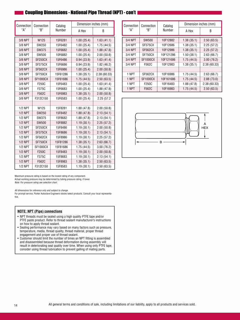
All general terms and conditions of sale, including limitations of our liability, apply to all products and services sold.14
Coupling Dimensions - National Pipe Thread (NPT) - con’t
Connection “B”
Connection “A”
CatalogNumber
Dimension inches (mm)
A Hex BConnection
“B”Connection
“A”CatalogNumber
Dimension inches (mm)
A Hex B
3/4 NPT SW500 10F12882 1.38 (35.1) 2.50 (63.5) 3/4 NPT SF375CX 10F12686 1.38 (35.1) 2.25 (57.2) 3/4 NPT SF562CX 10F12986 1.38 (35.1) 2.25 (57.2) 3/4 NPT SF750CX 10F121286 1.50 (38.1) 2.63 (66.7) 3/4 NPT SF1000CX 10F121686 1.75 (44.5) 3.00 (76.2) 3/4 NPT F562C 10F12983 1.38 (35.1) 2.38 (60.33) 1 NPT SF562CX 10F16986 1.75 (44.5) 2.63 (66.7) 1 NPT SF1000CX 10F161686 1.75 (44.5) 2.88 (73.0) 1 NPT F250C 10F16483 1.88 (47.8) 2.38 (60.33) 1 NPT F562C 10F16983 1.75 (44.5) 2.50 (63.5)
3/8 NPT W125 15F6281 1.00 (25.4) 1.63 (41.1) 3/8 NPT SW250 15F6482 1.00 (25.4) 1.75 (44.5) 3/8 NPT SW375 15F6682 1.00 (25.4) 1.88 (47.8) 3/8 NPT SW500 10F6882 1.00 (25.4) 2.00 (50.8) 3/8 NPT SF250CX 15F6486 0.94 (23.9) 1.63 (41.4) 3/8 NPT SF375CX 15F6686 0.94 (23.9) 1.82 (46.2) 3/8 NPT SF562CX 15F6986 1.00 (25.4) 2.00 (50.8) 3/8 NPT SF750CX 15F61286 1.38 (35.1) 2.38 (60.33) 3/8 NPT SF1000CX 15F61686 1.75 (44.5) 2.50 (63.5) 3/8 NPT F250C 15F6483 1.00 (25.4) 1.63 (41.4) 3/8 NPT F375C 15F6683 1.00 (25.4) 1.88 (47.8) 3/8 NPT F562C 15F6983 1.38 (35.1) 2.00 (50.8) 3/8 NPT F312C150 15F6583 1.00 (25.4) 2.25 (57.2
1/2 NPT W125 15F8281 1.88 (47.8) 2.00 (50.8) 1/2 NPT SW250 15F8482 1.88 (47.8) 2.13 (54.1) 1/2 NPT SW375 15F8682 1.88 (47.8) 2.13 (54.1) 1/2 NPT SW500 10F8882 1.19 (30.1) 2.25 (57.2) 1/2 NPT SF250CX 15F8486 1.19 (30.1) 2.00 (50.8) 1/2 NPT SF375CX 15F8686 1.19 (30.1) 2.13 (54.1) 1/2 NPT SF562CX 15F8986 1.19 (30.1) 2.25 (57.2) 1/2 NPT SF750CX 15F81286 1.38 (35.1) 2.63 (66.7) 1/2 NPT SF1000CX 15F81686 1.75 (44.5) 3.00 (76.2) 1/2 NPT F250C 15F8483 1.19 (30.1) 2.00 (50.8) 1/2 NPT F375C 15F8683 1.19 (30.1) 2.13 (54.1) 1/2 NPT F562C 15F8983 1.38 (35.1) 2.50 (63.5) 1/2 NPT F312C150 15F8583 1.19 (30.1) 2.50 (63.5)
Maximum pressure rating is based on the lowest rating of any component. Actual working pressure may be determined by tubing pressure rating, if lower.Note: For pressure rating see selection chart.
All dimensions for reference only and subject to change.For prompt service, Parker Autoclave Engineers stocks select products. Consult your local representa-tive.
AHEX
B
NOTE: NPT (Pipe) connections• NPT threads must be sealed using a high quality PTFE tape and/or PTFE paste product. Refer to thread sealant manufacturer’s instructions on how to apply thread sealant.• Sealing performance may vary based on many factors such as pressure, temperature, media, thread quality, thread material, proper thread engagement and proper use of thread sealant.• Customer should limit the number of times an NPT fitting is assembled and disassembled because thread deformation during assembly will result in deteriorating seal quality over time. When using only PTFE tape, consider using thread lubrication to prevent galling of mating parts.
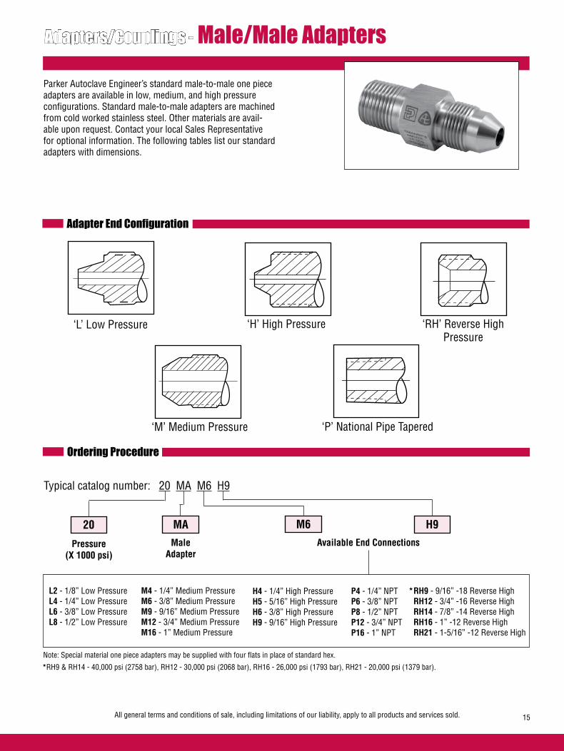
Adapters/Couplings - Male/Male Adapters
Parker Autoclave Engineer’s standard male-to-male one piece adapters are available in low, medium, and high pressure configurations. Standard male-to-male adapters are machined from cold worked stainless steel. Other materials are avail-able upon request. Contact your local Sales Representative for optional information. The following tables list our standard adapters with dimensions.
Adapter End Configuration
‘L’ Low Pressure ‘H’ High Pressure ‘RH’ Reverse High Pressure
‘M’ Medium Pressure
Ordering Procedure
Typical catalog number: 20 MA M6 H9
20
Pressure(X 1000 psi)
MAMale
Adapter
M6
M4 - 1/4” Medium PressureM6 - 3/8” Medium PressureM9 - 9/16” Medium PressureM12 - 3/4” Medium PressureM16 - 1” Medium Pressure
H9
P4 - 1/4” NPTP6 - 3/8” NPTP8 - 1/2” NPTP12 - 3/4” NPTP16 - 1” NPT
Available End Connections
L2 - 1/8” Low PressureL4 - 1/4” Low PressureL6 - 3/8” Low PressureL8 - 1/2” Low Pressure
All general terms and conditions of sale, including limitations of our liability, apply to all products and services sold. 15
‘P’ National Pipe Tapered
H4 - 1/4” High PressureH5 - 5/16” High PressureH6 - 3/8” High PressureH9 - 9/16” High Pressure
* RH9 - 9/16” -18 Reverse High RH12 - 3/4” -16 Reverse High RH14 - 7/8” -14 Reverse High RH16 - 1” -12 Reverse High RH21 - 1-5/16” -12 Reverse High
Note: Special material one piece adapters may be supplied with four flats in place of standard hex.
*RH9 & RH14 - 40,000 psi (2758 bar), RH12 - 30,000 psi (2068 bar), RH16 - 26,000 psi (1793 bar), RH21 - 20,000 psi (1379 bar).
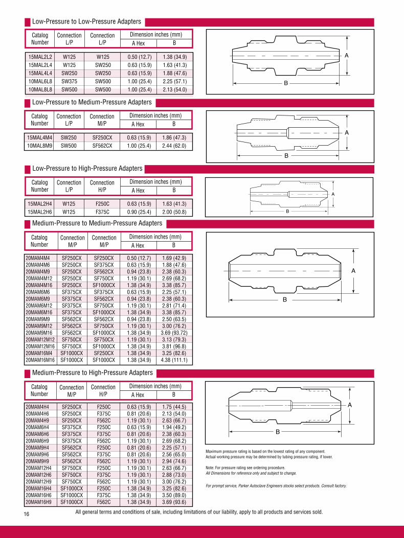
Low-Pressure to Low-Pressure Adapters
Medium-Pressure to Medium-Pressure Adapters
20MAM4H4 SF250CX F250C 0.63 (15.9) 1.75 (44.5) 20MAM4H6 SF250CX F375C 0.81 (20.6) 2.13 (54.0) 20MAM4H9 SF250CX F562C 1.19 (30.1) 2.63 (66.7) 20MAM6H4 SF375CX F250C 0.63 (15.9) 1.94 (49.2) 20MAM6H6 SF375CX F375C 0.81 (20.6) 2.38 (60.3) 20MAM6H9 SF375CX F562C 1.19 (30.1) 2.69 (68.2) 20MAM9H4 SF562CX F250C 0.81 (20.6) 2.25 (57.1) 20MAM9H6 SF562CX F375C 0.81 (20.6) 2.56 (65.0) 20MAM9H9 SF562CX F562C 1.19 (30.1) 2.94 (74.6) 20MAM12H4 SF750CX F250C 1.19 (30.1) 2.63 (66.7) 20MAM12H6 SF750CX F375C 1.19 (30.1) 2.88 (73.0) 20MAM12H9 SF750CX F562C 1.19 (30.1) 3.00 (76.2) 20MAM16H4 SF1000CX F250C 1.38 (34.9) 3.25 (82.6) 20MAM16H6 SF1000CX F375C 1.38 (34.9) 3.50 (89.0) 20MAM16H9 SF1000CX F562C 1.38 (34.9) 3.69 (93.6)
Medium-Pressure to High-Pressure Adapters
All general terms and conditions of sale, including limitations of our liability, apply to all products and services sold.16
A
B
B
A
A
B
Maximum pressure rating is based on the lowest rating of any component.Actual working pressure may be determined by tubing pressure rating, if lower.
Note: For pressure rating see ordering procedure.All Dimensions for reference only and subject to change.
For prompt service, Parker Autoclave Engineers stocks select products. Consult factory.
B
A
15MAL2L2 W125 W125 0.50 (12.7) 1.38 (34.9) 15MAL2L4 W125 SW250 0.63 (15.9) 1.63 (41.3) 15MAL4L4 SW250 SW250 0.63 (15.9) 1.88 (47.6) 10MAL6L8 SW375 SW500 1.00 (25.4) 2.25 (57.1) 10MAL8L8 SW500 SW500 1.00 (25.4) 2.13 (54.0)
20MAM4M4 SF250CX SF250CX 0.50 (12.7) 1.69 (42.9) 20MAM4M6 SF250CX SF375CX 0.63 (15.9) 1.88 (47.6) 20MAM4M9 SF250CX SF562CX 0.94 (23.8) 2.38 (60.3) 20MAM4M12 SF250CX SF750CX 1.19 (30.1) 2.69 (68.2) 20MAM4M16 SF250CX SF1000CX 1.38 (34.9) 3.38 (85.7) 20MAM6M6 SF375CX SF375CX 0.63 (15.9) 2.25 (57.1) 20MAM6M9 SF375CX SF562CX 0.94 (23.8) 2.38 (60.3) 20MAM6M12 SF375CX SF750CX 1.19 (30.1) 2.81 (71.4) 20MAM6M16 SF375CX SF1000CX 1.38 (34.9) 3.38 (85.7) 20MAM9M9 SF562CX SF562CX 0.94 (23.8) 2.50 (63.5) 20MAM9M12 SF562CX SF750CX 1.19 (30.1) 3.00 (76.2) 20MAM9M16 SF562CX SF1000CX 1.38 (34.9) 3.69 (93.72) 20MAM12M12 SF750CX SF750CX 1.19 (30.1) 3.13 (79.3) 20MAM12M16 SF750CX SF1000CX 1.38 (34.9) 3.81 (96.8) 20MAM16M4 SF1000CX SF250CX 1.38 (34.9) 3.25 (82.6) 20MAM16M16 SF1000CX SF1000CX 1.38 (34.9) 4.38 (111.1)
Connection L/P
Catalog Number
ConnectionL/P
Dimension inches (mm)A Hex B
Low-Pressure to Medium-Pressure Adapters
15MAL4M4 SW250 SF250CX 0.63 (15.9) 1.86 (47.3) 10MAL8M9 SW500 SF562CX 1.00 (25.4) 2.44 (62.0)
Connection L/P
Catalog Number
Dimension inches (mm)A Hex B
Catalog Number
Dimension inches (mm)A Hex B
Catalog Number
Dimension inches (mm)A Hex B
Low-Pressure to High-Pressure Adapters
15MAL2H4 W125 F250C 0.63 (15.9) 1.63 (41.3) 15MAL2H6 W125 F375C 0.90 (25.4) 2.00 (50.8)
Connection L/P
Catalog Number
Dimension inches (mm)A Hex B
B
A
ConnectionM/P
ConnectionH/P
ConnectionM/P
ConnectionM/P
ConnectionM/P
ConnectionH/P

A
B
Dimension inches (mm)
B
High-Pressure to High-Pressure Adapters
ConnectionNPT
Dimension inches (mm)
A Hex B
Medium-Pressure to NPT Adapters
Connection L/P
Catalog Number
ConnectionNPT
Dimension inches (mm)
A Hex B
Low-Pressure to NPT Adapters
All general terms and conditions of sale, including limitations of our liability, apply to all products and services sold. 17
A
B
A
B
Maximum pressure rating is based on the lowest rating of any component. Actual working pressure may be determined by tubing pressure rating, if lower.Note: For pressure rating see ordering procedure.All Dimensions for reference only and subject to change.
For prompt service, Parker Autoclave Engineers stocks select products. Consult factory.
NOTE: NPT (Pipe) connections• NPT threads must be sealed using a high quality PTFE tape and/or PTFE paste product. Refer to thread sealant manufacturer’s instructions on how to apply thread sealant.• Sealing performance may vary based on many factors such as pressure, temperature, media, thread quality, thread material, proper thread engagement and proper use of thread sealant.• Customer should limit the number of times an NPT fitting is assembled and disassembled because thread deformation during assembly will result in deteriorating seal quality over time. When using only PTFE tape, consider using thread lubrication to prevent galling of mating parts.
40MAH9H9 F562C40 F562C40 1.19 (30.1) 2.94 (74.6) 60MAH4H4 F250C F250C 0.63 (15.9) 1.69 (42.8) 60MAH4H5 F250C F312C150 0.75 (19.1) 2.63 (66.7) 60MAH4H6 F250C F375C 0.81 (20.6) 2.13 (54.0) 60MAH4H9 F250C F562C 1.19 (30.1) 2.56 (65.0) 60MAH5H6 F312C150 F375C 0.81 (20.6) 2.81 (71.4) 60MAH6H6 F375C F375C 0.81 (20.6) 2.25 (57.1) 60MAH6H9 F375C F562C 1.19 (30.1) 2.88 (73.0) 60MAH9H9 F562C F562C 1.19 (30.1) 3.00 (76.2) 150MAH5H5 F312C150 F312C150 0.75 (19.1) 3.38 (85.7)
Catalog Number
ConnectionH/P A Hex
Connection M/P
Catalog Number
15MAM4P4 SF250CX 1/4” 0.63 (15.9) 1.75 (44.5) 15MAM4P6 SF250CX 3/8” 0.75 (19.1) 1.81 (46.2) 15MAM4P8 SF250CX 1/2” 0.94 (23.8) 2.19 (55.5) 15MAM6P4 SF375CX 1/4” 0.63 (15.9) 1.94 (49.1) 15MAM6P6 SF375CX 3/8” 0.75 (19.1) 2.00 (50.8) 15MAM6P8 SF375CX 1/2” 0.94 (23.8) 2.38 (60.3) 15MAM9P4 SF562CX 1/4” 0.81 (20.6) 2.25 (57.1) 15MAM9P6 SF562CX 3/8” 0.81 (20.6) 2.13 (54.0) 15MAM9P8 SF562CX 1/2” 0.94 (23.8) 2.56 (65.0) 10MAM9P12 SF562CX 3/4” 1.19 (30.1) 2.75 (69.9) 10MAM9P16 SF562CX 1” 1.38 (34.9) 3.00 (76.2) 15MAM12P4 SF750CX 1/4” 1.19 (30.1) 2.63 (66.7) 15MAM12P6 SF750CX 3/8” 1.19 (30.1) 2.63 (66.7) 15MAM12P8 SF750CX 1/2” 1.19 (30.1) 2.81 (71.4) 10MAM12P12 SF750CX 3/4” 1.19 (30.1) 2.81 (71.4) 10MAM12P16 SF750CX 1” 1.19 (30.1) 2.81 (71.4) 15MAM16P4 SF1000CX 1/4” 1.38 (34.9) 3.38 (85.7) 15MAM16P6 SF1000CX 3/8” 1.38 (34.9) 3.31 (84.1) 15MAM16P8 SF1000CX 1/2” 1.38 (34.9) 3.44 (87.3) 10MAM16P12 SF1000CX 3/4” 1.50 (38.1) 3.75 (95.3) 10MAM16P16 SF1000CX 1” 1.50 (38.1) 4.00 (101.6)
15MAL2P2 W125 1/8” 0.50 (12.7) 1.38 (34.9) 15MAL2P4 W125 1/4” 0.63 (15.9) 1.63 (41.2) 15MAL2P8 W125 1/2” 1.00 (25.4) 2.13 (54.0) 15MAL4P8 SW250 1/2” 1.00 (25.4) 2.25 (57.1) 15MAL4P2 SW250 1/8” 0.63 (15.9) 1.63 (41.2) 15MAL4P4 SW250 1/4” 0.63 (15.9) 1.75 (44.5) 15MAL6P4 SW375 1/4” 0.75 (19.1) 1.88 (47.6) 15MAL6P8 SW375 1/2” 1.00 (25.4) 2.25 (57.1) 10MAL8P6 SW500 3/8” 1.00 (25.4) 2.00 (50.0) 10MAL8P8 SW500 1/2” 1.00 (25.4) 2.31 (58.7) 10MAL8P12 SW500 3/4” 1.19 (30.1) 2.38 (60.3)
Connection H/P

A
B
Connection H/P
Catalog Number
ConnectionNPT
Dimension inches (mm)
A Hex B
High-Pressure to NPT Adapters
Connection M/P
Catalog Number
ConnectionRH
Dimension inches (mm)
A Hex B
Medium-Pressure to Reverse High-Pressure Adapters
Connection NPT
Catalog Number
ConnectionNPT
Dimension inches (mm)
A Hex B
NPT to NPT Adapters
All general terms and conditions of sale, including limitations of our liability, apply to all products and services sold.18
A
B
A
B
Maximum pressure rating is based on the lowest rating of any component. Actual working pressure may be determined by tubing pressure rating, if lower.Note: For pressure rating see ordering procedure.All Dimensions for reference only and are subject to change. For prompt service, Parker Autoclave Engineers stocks select products. Consult factory.
15MAH4P4 F250C 1/4” 0.63 (15.9) 1.81 (46.2) 15MAH4P6 F250C 3/8” 0.75 (19.1) 1.88 (47.6) 15MAH4P8 F250C 1/2” 0.94 (23.8) 2.25 (57.1) 15MAH6P4 F375C 1/4” 0.81 (20.6) 2.13 (54.0) 15MAH6P6 F375C 3/8” 0.81 (20.6) 2.13 (54.0) 15MAH6P8 F375C 1/2” 0.94 (23.8) 2.50 (63.5) 15MAH9P4 F562C 1/4” 1.19 (30.1) 2.63 (66.7) 15MAH9P6 F562C 3/8” 1.19 (30.1) 2.56 (65.0) 15MAH9P8 F562C 1/2” 1.19 (30.1) 2.75 (69.9)
15MAP4P4 1/4 1/4” 0.63 (15.9) 1.81 (46.2) 15MAP4P6 1/4 3/8” 0.75 (19.1) 1.88 (47.6) 15MAP4P8 1/4 1/2” 0.94 (23.8) 2.31 (58.7) 15MAP6P6 3/8 3/8” 0.75 (19.1) 1.88 (47.6) 15MAP6P8 3/8 1/2” 0.94 (23.8) 2.31 (58.7) 15MAP8P8 1/2 1/2” 0.94 (23.8) 2.50 (63.5)
20MAM4RH9 SF250CX 9/16” 0.63 (15.9) 1.56 (39.7) 20MAM4RH12 SF250CX 3/4” 0.81 (20.6) 1.88 (47.6) 20MAM4RH16 SF250CX 1” 1.00 (25.4) 2.13 (54.0) 20MAM6RH9 SF375CX 9/16” 0.63 (15.9) 1.69 (42.8) 20MAM6RH12 SF375CX 3/4” 0.81 (20.6) 1.81 (46.2) 20MAM6RH16 SF375CX 1” 1.00 (25.4) 2.25 (57.1) 20MAM9RH9 SF562CX 9/16” 0.94 (23.8) 2.00 (50.8) 20MAM9RH12 SF562CX 3/4” 0.94 (23.8) 2.13 (54.0) 20MAM9RH14 SF562CX 7/8” 0.94 (23.8) 2.44 (61.9) 20MAM9RH16 SF562CX 1” 1.00 (25.4) 2.25 (57.1) 20MAM9RH21 SF562CX 1-5/16” 1.38 (34.9) 2.38 (60.3) 20MAM12RH9 SF750CX 9/16” 1.19 (30.1) 2.38 (60.3) 20MAM12RH12 SF750CX 3/4” 1.19 (30.1) 2.44 (61.9) 20MAM12RH16 SF750CX 1” 1.19 (30.1) 2.50 (63.5) 20MAM12RH21 SF750CX 1-5/16” 1.50 (38.1) 2.75 (69.9) 20MAM16RH9 SF1000CX 9/16” 1.38 (34.9) 3.13 (79.3) 20MAM16RH12 SF1000CX 3/4” 1.38 (34.9) 3.19 (80.9) 20MAM16RH14 SF1000CX 7/8” 1.38 (34.9) 3.34 (84.9) 20MAM16RH16 SF1000CX 1” 1.38 (34.9) 3.38 (85.7) 20MAM16RH21 SF1000CX 1-5/16” 1.50 (38.1) 3.25 (82.6)
NOTE: NPT (Pipe) connections• NPT threads must be sealed using a high quality PTFE tape and/or PTFE paste product. Refer to thread sealant manufacturer’s instructions on how to apply thread sealant.• Sealing performance may vary based on many factors such as pressure, temperature, media, thread quality, thread material, proper thread engagement and proper use of thread sealant.• Customer should limit the number of times an NPT fitting is assembled and disassembled because thread deformation during assembly will result in deteriorating seal quality over time. When using only PTFE tape, consider using thread lubrication to prevent galling of mating parts.

Connection H/P
Catalog Number
ConnectionRH
Dimension inches (mm)
A Hex B
26MAH4RH16 F250C 1” 1.00 (25.4) 2.13 (54.0) 26MAH6RH16 F375C 1” 1.00 (25.4) 2.25 (57.1) 26MAH9RH16 F562C 1” 1.19 (30.1) 2.69 (68.2) 30MAH4RH12 F250C 3/4” 0.81 (20.6) 1.88 (47.6) 30MAH6RH12 F375C 3/4” 0.81 (20.6) 2.06 (54.0) 30MAH9RH12 F562C 3/4” 1.19 (30.1) 2.50 (63.5) 40MAH4RH9 F250C 9/16” 0.63 (15.9) 1.56 (39.7) 40MAH6RH9 F375C 9/16” 0.81 (20.6) 1.94 (49.1) 40MAH9RH9 F562C 9/16” 1.19 (30.1) 2.38 (60.3)
High-Pressure to Reverse High-Pressure Adapters
Connection NPT
Catalog Number
ConnectionRH
Dimension inches (mm)
A Hex B
NPT to Reverse High-Pressure Adapters
Connection RH
Catalog Number
ConnectionRH
Dimension inches (mm)
A Hex B
Reverse High-Pressure to Reverse High-Pressure Adapters
All general terms and conditions of sale, including limitations of our liability, apply to all products and services sold. 19
B
A
A
B
A
B
Maximum pressure rating is based on the lowest rating of any component. Actual working pressure may be determined by tubing pressure rating, if lower.
Note: For pressure rating see ordering procedure.
All Dimensions for reference only and are subject to change. For prompt service, Parker Autoclave Engineers stocks select products. Consult factory.
15MAP4RH9 1/4 9/16” 0.63 (15.9) 1.63 (41.2) 15MAP4RH12 1/4 3/4” 0.81 (20.6) 1.88 (47.6) 15MAP4RH16 1/4 1” 1.00 (25.4) 2.25 (57.1) 15MAP6RH9 3/8 9/16” 0.75 (19.1) 1.81 (46.2) 15MAP6RH12 3/8 3/4” 0.81 (20.6) 1.94 (49.1) 15MAP6RH16 3/8 1” 1.00 (25.4) 2.13 (54.0) 15MAP8RH9 1/2 9/16” 0.94 (23.8) 2.00 (50.8) 15MAP8RH12 1/2 3/4” 0.94 (23.8) 2.13 (54.0) 15MAP8RH14 1/2 7/8” 1.00 (25.4) 2.25 (57.1) 15MAP8RH16 1/2 1” 1.00 (25.4) 2.31 (58.7) 10MAP12RH12 3/4 3/4” 1.19 (30.1) 2.31 (58.7) 10MAP12RH16 3/4 1” 1.38 (34.9) 2.63 (66.7) 10MAP12RH21 3/4 1-5/16” 1.38 (34.9) 2.63 (66.7) 10MAP16RH9 1 9/16” 1.38 (34.9) 2.25 (57.2) 10MAP16RH16 1 1” 1.38 (34.9) 2.81 (71.4) 10MAP16RH21 1 1-5/16” 1.38 (34.9) 2.68 (68.0)
20MARH21RH21 1-5/16 1-5/16” 1.38 (34.9) 2.13 (54.1)
26MARH9RH16 9/16 1” 1.00 (25.4) 1.88 (47.6) 26MARH12RH16 3/4 1” 1.00 (25.4) 2.00 (50.8) 26MARH16RH16 1 1” 1.00 (25.4) 2.00 (50.8) 30MARH9RH12 9/16 3/4” 0.81 (20.6) 1.63 (41.2) 30MARH12RH12 3/4 3/4” 0.81 (20.6) 1.75 (44.5) 40MARH9RH9 9/16 9/16” 0.63 (15.9) 1.50 (38.1)
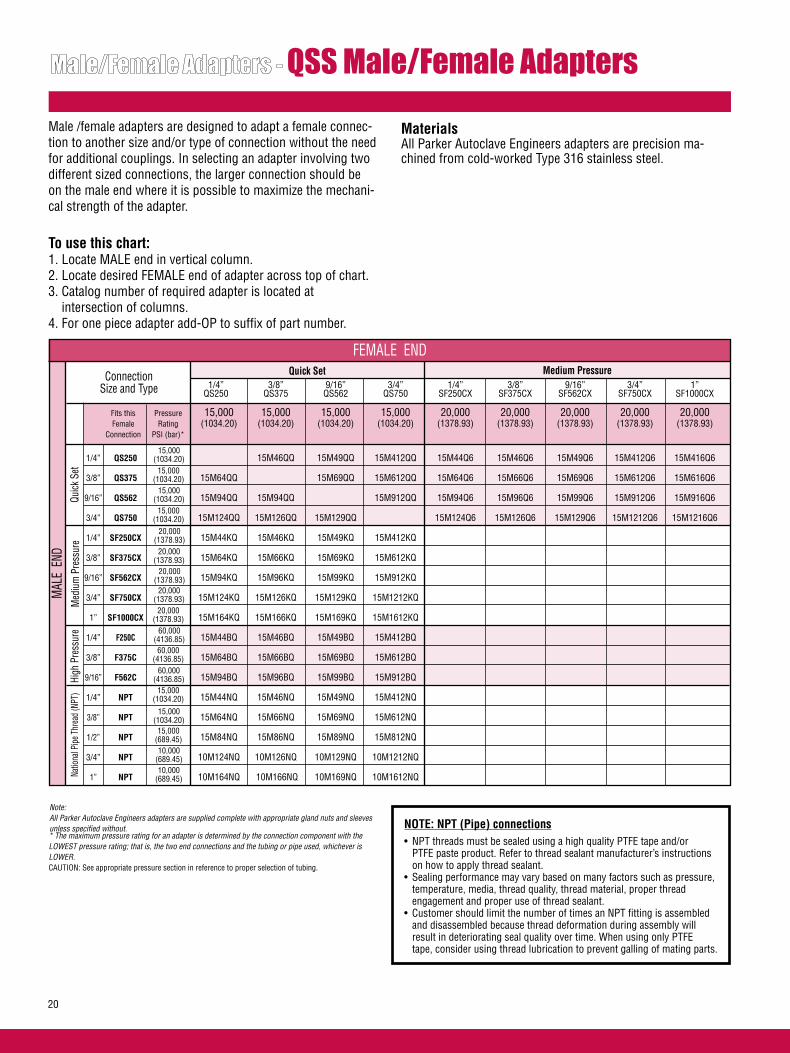
QSS Male/Female Adapters
Male /female adapters are designed to adapt a female connec-tion to another size and/or type of connection without the need for additional couplings. In selecting an adapter involving two different sized connections, the larger connection should be on the male end where it is possible to maximize the mechani-cal strength of the adapter. To use this chart:1. Locate MALE end in vertical column.2. Locate desired FEMALE end of adapter across top of chart.3. Catalog number of required adapter is located at intersection of columns.4. For one piece adapter add-OP to suffix of part number.
ConnectionSize and Type
Quick Set
Quick
Set
Med
ium
Pre
ssur
e
Note:All Parker Autoclave Engineers adapters are supplied complete with appropriate gland nuts and sleeves unless specified without.
MaterialsAll Parker Autoclave Engineers adapters are precision ma-chined from cold-worked Type 316 stainless steel.
Medium Pressure
High
Pre
ssur
eNa
tiona
l Pipe
Thr
ead
(NPT
)
* The maximum pressure rating for an adapter is determined by the connection component with the LOWEST pressure rating; that is, the two end connections and the tubing or pipe used, whichever is LOWER. CAUTION: See appropriate pressure section in reference to proper selection of tubing.
FEMALE END
MAL
E E
ND
NOTE: NPT (Pipe) connections• NPT threads must be sealed using a high quality PTFE tape and/or PTFE paste product. Refer to thread sealant manufacturer’s instructions on how to apply thread sealant.• Sealing performance may vary based on many factors such as pressure, temperature, media, thread quality, thread material, proper thread engagement and proper use of thread sealant.• Customer should limit the number of times an NPT fitting is assembled and disassembled because thread deformation during assembly will result in deteriorating seal quality over time. When using only PTFE tape, consider using thread lubrication to prevent galling of mating parts.
20
1/4” 3/8” 9/16” 3/4” 1/4” 3/8” 9/16” 3/4” 1” QS250 QS375 QS562 QS750 SF250CX SF375CX SF562CX SF750CX SF1000CX
Fits this Pressure 15,000 15,000 15,000 15,000 20,000 20,000 20,000 20,000 20,000 Female Rating (1034.20) (1034.20) (1034.20) (1034.20) (1378.93) (1378.93) (1378.93) (1378.93) (1378.93) Connection PSI (bar)*
1/4” QS250 15M46QQ 15M49QQ 15M412QQ 15M44Q6 15M46Q6 15M49Q6 15M412Q6 15M416Q6
3/8” QS375 15M64QQ 15M69QQ 15M612QQ 15M64Q6 15M66Q6 15M69Q6 15M612Q6 15M616Q6
9/16” QS562 15M94QQ 15M94QQ 15M912QQ 15M94Q6 15M96Q6 15M99Q6 15M912Q6 15M916Q6
3/4” QS750 15M124QQ 15M126QQ 15M129QQ 15M124Q6 15M126Q6 15M129Q6 15M1212Q6 15M1216Q6
1/4” SF250CX 15M44KQ 15M46KQ 15M49KQ 15M412KQ
3/8” SF375CX 15M64KQ 15M66KQ 15M69KQ 15M612KQ
9/16” SF562CX 15M94KQ 15M96KQ 15M99KQ 15M912KQ
3/4” SF750CX 15M124KQ 15M126KQ 15M129KQ 15M1212KQ
1” SF1000CX 15M164KQ 15M166KQ 15M169KQ 15M1612KQ
1/4” F250C 15M44BQ 15M46BQ 15M49BQ 15M412BQ
3/8” F375C 15M64BQ 15M66BQ 15M69BQ 15M612BQ
9/16” F562C 15M94BQ 15M96BQ 15M99BQ 15M912BQ
1/4” NPT 15M44NQ 15M46NQ 15M49NQ 15M412NQ
3/8” NPT 15M64NQ 15M66NQ 15M69NQ 15M612NQ
1/2” NPT 15M84NQ 15M86NQ 15M89NQ 15M812NQ
3/4” NPT 10M124NQ 10M126NQ 10M129NQ 10M1212NQ
1” NPT 10M164NQ 10M166NQ 10M169NQ 10M1612NQ
15,000(1034.20)
15,000(1034.20)
15,000(1034.20)
15,000(1034.20)
20,000(1378.93)
20,000(1378.93)
20,000(1378.93)
20,000(1378.93)20,000
(1378.93)60,000
(4136.85)60,000
(4136.85)60,000
(4136.85)15,000
(1034.20)
15,000(1034.20)
15,000(689.45)10,000
(689.45)10,000
(689.45)

High Pressure 1/4” 3/8” 9/16” 1/4” 3/8” 1/2” 3/4” 1” F250C F375C F562C NPT NPT NPT NPT NPT
60,000 60,000 150,000 15,000 15,000 15,000 10,000 10,000 (4136.85) (4136.85) (10342.14) (1034.20) (1034.20) (1034.20) (689.45) (689.45)
15M44Q3 15M46Q3 15M49Q3 15M44Q8 15M46Q8 15M48Q8 10M412Q8 10M416Q8
15M64Q3 15M66Q3 15M69Q3 15M64Q8 15M66Q8 15M68Q8 10M612Q8 10M616Q8
15M94Q3 15M96Q3 15M99Q3 15M94Q8 15M96Q8 15M98Q8 10M912Q8 10M916Q8
15M124Q3 15M126Q3 15M129Q3 15M124Q8 15M126Q8 15M128Q8 10M1212Q8 10M1216Q8
National Pipe Thread (NPT)
AE Male/Female Adapters are available in a “one-piece” design. They are identical to the two piece designs in length and can be ordered by adding the suffix - OP to the two piece adapter part numbers listed.
For prompt service, Parker Autoclave Engineers stocks select products. Consult factory.factory.
FEMALE END
Quick Set Femaleto
Quick Set Male
Quick Set Femaleto
Medium Pressure Male
Quick Set Femaleto
High Pressure Male
Quick Set Femaleto
National Pipe Male
21

QS Series
Female End
Male End Fits this
Connection
CatalogNumber
Dimension inches (mm)
A Hex BFemale
EndCatalogNumber
Dimension inches (mm)
A Hex B
For prompt service, Parker Autoclave Engineers stocks select products. Consult factory. Maximum pressure rating is based on the lowest rating of any component. Actual working pressure may be determined by tubing pressure rating, if lower.Note: For pressure rating see selection chart.All Dimensions for reference only and subject to change.
Male End Fits this
Connection
AHEX
B
AHEX
B
QSS to Pipe QSS to QSS
QS250 QS250 QS250 QS375 15M46QQ QS250 QS562 15M49QQ 1.38 (34.9) 2.25 (57.1) QS250 QS750 15M412QQ QS250 SF250CX 15M44Q6 QS250 SF375CX 15M46Q6 QS250 SF562CX 15M49Q6 QS250 SF750CX 15M412Q6 QS250 SF1000CX 15M416Q6 QS250 F250C 15M44Q3 QS250 F375C 15M46Q3 QS250 F562C 10M49Q3 QS250 1/4 NPT 15M44Q8 0.75 (19.1) 1.69 (42.9) QS250 3/8 NPT 15M46Q8 QS250 1/2 NPT 15M48Q8 QS250 3/4 NPT 10M412Q8 QS250 1 NPT 10M416Q8 QS375 QS250 15M64QQ 0.75 (19.1) 1.53 (38.9) QS375 QS375 QS375 QS562 15M69QQ QS375 QS750 15M612QQ 1.50 (38.1) 2.78 (70.6) QS375 SF250CX 15M64Q6 QS375 SF375CX 15M66Q6 0.75 (19.1) 1.66 (42.2) QS375 SF562CX 15M69Q6 1.00 (25.4) 1.78 (45.2) QS375 SF750CX 15M612Q6 QS375 SF1000CX 15M616Q6 QS375 F250C 15M64Q3 QS375 F375C 15M66Q3 QS375 F562C 15M69Q3 QS375 1/4 NPT 15M64Q8 0.75 (19.1) 1.66 (42.2) QS375 3/8 NPT 15M66Q8 1.00 (25.4) 1.78 (45.3) QS375 1/2 NPT 15M68Q8 1.19 (30.1) 2.16 (54.8) QS375 3/4 NPT 10M612Q8 QS375 1 NPT 10M616Q8
QS562 QS250 15M94QQ 1.00 (25.4) 1.85 (46.8) QS562 QS375 15M96QQ 1.00 (25.4) 1.85 (46.8) QS562 QS562 QS562 QS750 15M912QQ 1.50 (38.1) 3.16 (80.3) QS562 SF250CX 15M94Q6 QS562 SF375CX 15M96Q6 QS562 SF562CX 15M99Q6 QS562 SF750CX 15M912Q6 QS562 SF1000CX 15M916Q6 QS562 F250C 15M94Q3 QS562 F375C 15M96Q3 QS562 F562C 15M99Q3 QS562 1/4 NPT 15M94Q8 1.19 (30.1) 2.22 (56.4) QS562 3/8 NPT 15M96Q8 1.19 (30.1) 2.22 (56.4) QS562 1/2 NPT 15M98Q8 1.19 (30.1) 2.41 (61.1) QS562 3/4 NPT 10M912Q8 QS562 1 NPT 10M916Q8 QS750 QS250 15M124QQ QS750 QS375 15M126QQ 1.50 (38.1) 2.53 (64.1) QS750 QS562 15M129QQ 1.50 (38.1) 2.53 (64.1) QS750 QS750 QS750 SF250CX 15M124Q6 QS750 SF375CX 15M126Q6 QS750 SF562CX 15M129Q6 QS750 SF750CX 15M1212Q6 QS750 SF1000CX 15M1216Q6 QS750 F250C 15M124Q3 QS750 F375C 15M126Q3 QS750 F562C 15M129Q3 QS750 1/4 NPT 15M124Q8 QS750 3/8 NPT 15M126Q8 QS750 1/2 NPT 15M128Q8 1.50 (38.1) 2.78 (70.5) QS750 3/4 NPT 10M1212Q8 QS750 1 NPT 10M1216Q8
22

SF562CX QS250 15M94KQ 0.94 (23.8) 1.75 (44.5) SF562CX QS375 15M96KQ 0.94 (23.8) 1.75 (44.5) SF562CX QS562 15M99KQ 1.38 (34.9) 2.50 (63.5) SF562CX QS750 15M912KQ 1.50 (38.1) 3.25 (82.6)
SF750CX QS250 15M124KQ SF750CX QS375 15M126KQ SF750CX QS562 15M129KQ SF750CX QS750 15M1212KQ 1.50 (38.1) 3.06 (77.7)
SF1000CX QS250 15M164KQ SF1000CX QS375 15M166KQ SF1000CX QS562 15M169KQ 1.50 (38.1) 2.88 (73.0) SF1000CX QS750 15M1612KQ 1.50 (38.1) 3.38 (85.7)
Maximum pressure rating is based on the lowest rating of any component. Actual working pressure may be determined by tubing pressure rating, if lower.Note: For pressure rating see selection chart.All Dimensions for reference only and subject to change.Adapter configurations may vary from outline shown.
FFor prompt service, Parker Autoclave Engineers stocks select products. Consult factory.
F375C QS250 15M64BQ F375C QS375 15M66BQ 0.81 (20.6) 1.69 (42.9) F375C QS562 15M69BQ F375C QS750 15M612BQ
F562C QS250 15M94BQ 1.19 (30.1) 1.81(46.1) F562C QS375 15M96BQ 1.19 (30.1) 1.69 (42.9) F562C QS562 15M99BQ 1.38 (34.9) 2.32 (58.8) F562C QS750 15M912BQ 1.50 (38.1) 3.06 (77.7)
SF250CX QS250 15M44KQ 0.75 (19.1) 1.68 (42.7) SF250CX QS375 15M46KQ 0.81 (20.6) 1.68 (42.7) SF250CX QS562 15M49KQ 1.19 (30.1) 2.22 (56.4) SF250CX QS750 15M412KQ
SF375CX QS250 15M64KQ 0.75 (19.1) 1.63 (41.4) SF375CX QS375 15M66KQ 0.81 (20.6) 1.81 (46.1) SF375CX QS562 15M69KQ SF375CX QS750 15M612KQ 1.50 (38.1) 3.00 (76.20)
F250C QS250 15M44BQ 0.75 (19.1) 1.31 (33.3) F250C QS375 15M46BQ 0.81 (20.6) 1.56 (39.7) F250C QS562 15M49BQ F250C QS750 15M412BQ
B
AHEX
MP to QSS HP to QSS
B
AHEX
QS Series
Female End
Male End Fits this
Connection
CatalogNumber
Dimension inches (mm)
A Hex BFemale
EndCatalogNumber
Dimension inches (mm)
A Hex B
Male End Fits this
Connection
23

3/4 NPT QS250 10M124NQ 3/4 NPT QS375 10M126NQ 3/4 NPT QS562 10M129NQ 1.38 (35.1) 2.38 (60.3) 3/4 NPT QS750 10M1212NQ 1.50 (38.1) 2.81 (71.4)
1 NPT QS250 10M164NQ 1 NPT QS275 10M166NQ 1 NPT QS562 10M169NQ 1.50 (38.1) 2.38 (60.3) 1 NPT QS750 10M1612NQ 1.50 (38.1) 2.38 (60.3)
Maximum pressure rating is based on the lowest rating of any component. Actual working pressure may be determined by tubing pressure rating, if lower.Note: For pressure rating see selection chart.All Dimensions for reference only and subject to change.Adapter configurations may vary from outline shown.
For prompt service, Parker Autoclave Engineers stocks select products. Consult factory.
B
AHEX
NPT to QSS
QS Series
Female End
Male End Fits this
Connection
CatalogNumber
Dimension inches (mm)
A Hex B
24
1/4 NPT QS250 15M44NQ 0.75 (19.1) 1.44 (36.5) 1/4 NPT QS375 15M46NQ 0.81 (20.6) 1.63 (41.3) 1/4 NPT QS562 15M49NQ 1/4 NPT QS750 15M412NQ 3/8 NPT QS250 15M64NQ 0.75 (19.1) 1.50 (38.1) 3/8 NPT QS375 15M66NQ 0.81 (20.6) 1.63 (41.3) 3/8 NPT QS562 15M69NQ 1.38 (35.1) 2.13 (53.5) 3/8 NPT QS750 15M612NQ
1/2 NPT QS250 15M84NQ 0.94 (23.8) 1.75 (44.5) 1/2 NPT QS375 15M86NQ 0.94 (23.8) 1.63 (41.3) 1/2 NPT QS562 15M89NQ 1.38 (35.1) 2.25 (57.2) 1/2 NPT QS750 15M812NQ 1.50 (38.1) 2.81 (71.4)
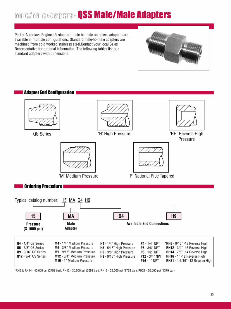
QSS Male/Male Adapters
Parker Autoclave Engineer’s standard male-to-male one piece adapters are available in multiple configurations. Standard male-to-male adapters are machined from cold worked stainless steel.Contact your local Sales Representative for optional information. The following tables list our standard adapters with dimensions.
Adapter End Configuration
QS Series ‘H’ High Pressure ‘RH’ Reverse High Pressure
‘M’ Medium Pressure
Ordering Procedure
Typical catalog number: 15 MA Q4 H9
15
Pressure(X 1000 psi)
MAMale
Adapter
Q4
M4 - 1/4” Medium PressureM6 - 3/8” Medium PressureM9 - 9/16” Medium PressureM12 - 3/4” Medium PressureM16 - 1” Medium Pressure
H9
P4 - 1/4” NPTP6 - 3/8” NPTP8 - 1/2” NPTP12 - 3/4” NPTP16 - 1” NPT
Available End Connections
Q4 - 1/4” QS SeriesQ6 - 3/8” QS SeriesQ9 - 9/16” QS SeriesQ12 - 3/4” QS Series
‘P’ National Pipe Tapered
H4 - 1/4” High PressureH5 - 5/16” High PressureH6 - 3/8” High PressureH9 - 9/16” High Pressure
* RH9 - 9/16” -18 Reverse High RH12 - 3/4” -16 Reverse High RH14 - 7/8” -14 Reverse High RH16 - 1” -12 Reverse High RH21 - 1-5/16” -12 Reverse High
*RH9 & RH14 - 40,000 psi (2758 bar), RH12 - 30,000 psi (2068 bar), RH16 - 26,000 psi (1793 bar), RH21 - 20,000 psi (1379 bar).
25

Catalog Number
ConnectionRH
Dimension inches (mm)
A Hex B
QS Series to Reverse High-Pressure Adapters
Connection QS
15MAQ4RH9 QS250 9/16” 0.63 (15.9) 1.70 (43.2) 15MAQ6RH9 QS375 9/16” 0.75 (19.1) 1.81 (46.2) 15MAQ9RH9 QS562 9/16” 1.19 (30.1) 2.25 (57.1) 15MAQ9RH12 QS562 3/4” 1.19 (30.1) 2.38 (60.3) 15MAQ9RH16 QS562 1” 1.19 (30.1) 2.56 (65.1)
A
B
Catalog Number
Dimension inches (mm)
A Hex BConnection
QS
15MAQ9H4 QS562 1/4” 0.75 (19.1) 2.00 (50.8)
A
B
QS Series to High-Pressure Adapter
ConnectionH/P
Catalog Number
Dimension inches (mm)
A Hex BConnection
QS
15MAQ6P4 QS375 1/4” 0.75 (19.1) 2.00 (50.8)
QS Series to NPT Adapter
ConnectionNPT
A
B
26
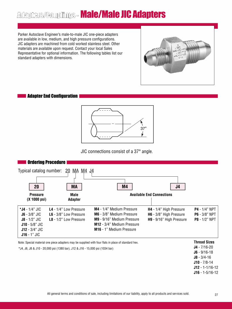
Adapters/Couplings - Male/Male JIC Adapters
Parker Autoclave Engineer’s male-to-male JIC one-piece adapters are available in low, medium, and high pressure configurations. JIC adapters are machined from cold worked stainless steel. Other materials are available upon request. Contact your local Sales Representative for optional information. The following tables list our standard adapters with dimensions.
Adapter End Configuration
JIC connections consist of a 37° angle.
Ordering ProcedureTypical catalog number: 20 MA M4 J4
20
Pressure(X 1000 psi)
MA M4 J4
Available End Connections
L4 - 1/4” Low PressureL6 - 3/8” Low PressureL8 - 1/2” Low Pressure
M4 - 1/4” Medium PressureM6 - 3/8” Medium PressureM9 - 9/16” Medium PressureM12 - 3/4” Medium PressureM16 - 1” Medium Pressure
H4 - 1/4” High PressureH6 - 3/8” High PressureH9 - 9/16” High Pressure
P4 - 1/4” NPTP6 - 3/8” NPTP8 - 1/2” NPT
All general terms and conditions of sale, including limitations of our liability, apply to all products and services sold. 27
MaleAdapter
Note: Special material one piece adapters may be supplied with four flats in place of standard hex.
*J4 - 1/4” JIC J6 - 3/8” JIC J8 - 1/2” JIC J10 - 5/8” JIC J12 - 3/4” JIC J16 - 1” JIC
*J4, J6, J8 & J10 - 20,000 psi (1380 bar), J12 & J16 - 15,000 psi (1034 bar)
Thread SizesJ4 - 7/16-20J6 - 9/16-18J8 - 3/4-16J10 - 7/8-14J12 - 1-1/16-12J16 - 1-5/16-12
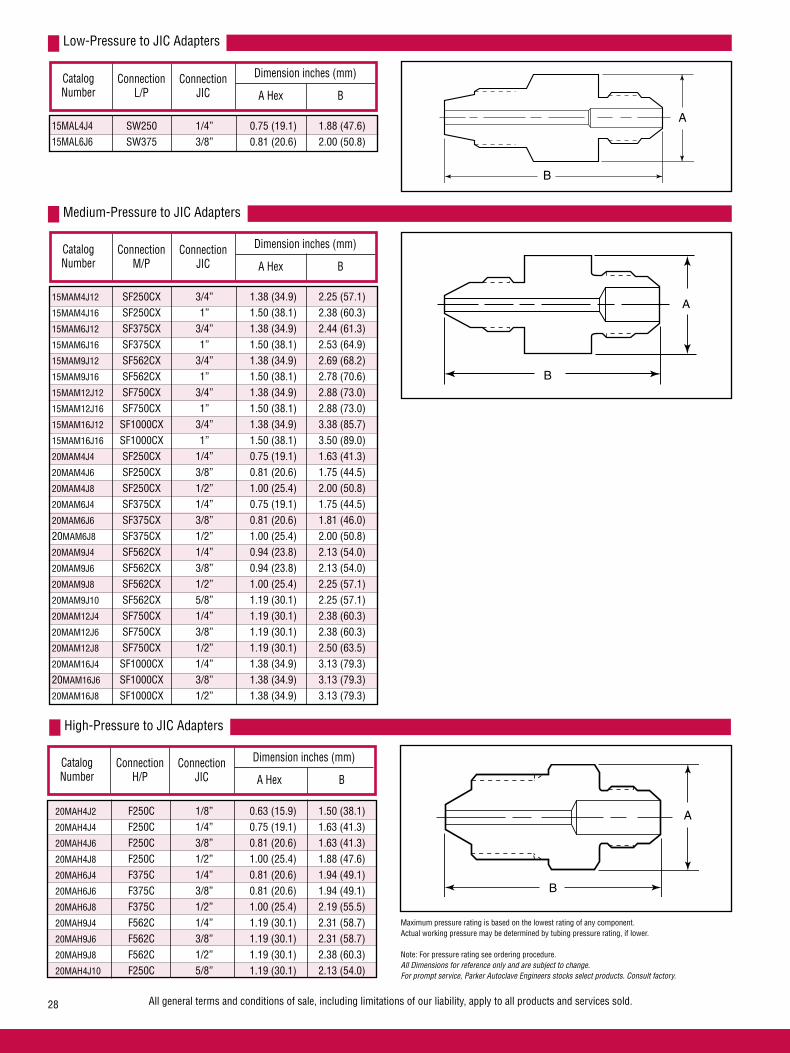
Connection L/P
Catalog Number
ConnectionJIC
Dimension inches (mm)
A Hex B
Low-Pressure to JIC Adapters
Connection M/P
Catalog Number
ConnectionJIC
Dimension inches (mm)
A Hex B
Medium-Pressure to JIC Adapters
Connection H/P
Catalog Number
ConnectionJIC
Dimension inches (mm)
A Hex B
High-Pressure to JIC Adapters
All general terms and conditions of sale, including limitations of our liability, apply to all products and services sold.28
A
B
B
A
A
B
Maximum pressure rating is based on the lowest rating of any component. Actual working pressure may be determined by tubing pressure rating, if lower.
Note: For pressure rating see ordering procedure.All Dimensions for reference only and are subject to change. For prompt service, Parker Autoclave Engineers stocks select products. Consult factory.
20MAH4J2 F250C 1/8” 0.63 (15.9) 1.50 (38.1) 20MAH4J4 F250C 1/4” 0.75 (19.1) 1.63 (41.3) 20MAH4J6 F250C 3/8” 0.81 (20.6) 1.63 (41.3) 20MAH4J8 F250C 1/2” 1.00 (25.4) 1.88 (47.6) 20MAH6J4 F375C 1/4” 0.81 (20.6) 1.94 (49.1) 20MAH6J6 F375C 3/8” 0.81 (20.6) 1.94 (49.1) 20MAH6J8 F375C 1/2” 1.00 (25.4) 2.19 (55.5) 20MAH9J4 F562C 1/4” 1.19 (30.1) 2.31 (58.7) 20MAH9J6 F562C 3/8” 1.19 (30.1) 2.31 (58.7) 20MAH9J8 F562C 1/2” 1.19 (30.1) 2.38 (60.3) 20MAH4J10 F250C 5/8” 1.19 (30.1) 2.13 (54.0)
15MAL4J4 SW250 1/4” 0.75 (19.1) 1.88 (47.6) 15MAL6J6 SW375 3/8” 0.81 (20.6) 2.00 (50.8)
15MAM4J12 SF250CX 3/4” 1.38 (34.9) 2.25 (57.1) 15MAM4J16 SF250CX 1” 1.50 (38.1) 2.38 (60.3) 15MAM6J12 SF375CX 3/4” 1.38 (34.9) 2.44 (61.3) 15MAM6J16 SF375CX 1” 1.50 (38.1) 2.53 (64.9) 15MAM9J12 SF562CX 3/4” 1.38 (34.9) 2.69 (68.2) 15MAM9J16 SF562CX 1” 1.50 (38.1) 2.78 (70.6) 15MAM12J12 SF750CX 3/4” 1.38 (34.9) 2.88 (73.0) 15MAM12J16 SF750CX 1” 1.50 (38.1) 2.88 (73.0) 15MAM16J12 SF1000CX 3/4” 1.38 (34.9) 3.38 (85.7) 15MAM16J16 SF1000CX 1” 1.50 (38.1) 3.50 (89.0) 20MAM4J4 SF250CX 1/4” 0.75 (19.1) 1.63 (41.3) 20MAM4J6 SF250CX 3/8” 0.81 (20.6) 1.75 (44.5) 20MAM4J8 SF250CX 1/2” 1.00 (25.4) 2.00 (50.8) 20MAM6J4 SF375CX 1/4” 0.75 (19.1) 1.75 (44.5) 20MAM6J6 SF375CX 3/8” 0.81 (20.6) 1.81 (46.0) 20MAM6J8 SF375CX 1/2” 1.00 (25.4) 2.00 (50.8) 20MAM9J4 SF562CX 1/4” 0.94 (23.8) 2.13 (54.0) 20MAM9J6 SF562CX 3/8” 0.94 (23.8) 2.13 (54.0) 20MAM9J8 SF562CX 1/2” 1.00 (25.4) 2.25 (57.1) 20MAM9J10 SF562CX 5/8” 1.19 (30.1) 2.25 (57.1) 20MAM12J4 SF750CX 1/4” 1.19 (30.1) 2.38 (60.3) 20MAM12J6 SF750CX 3/8” 1.19 (30.1) 2.38 (60.3) 20MAM12J8 SF750CX 1/2” 1.19 (30.1) 2.50 (63.5) 20MAM16J4 SF1000CX 1/4” 1.38 (34.9) 3.13 (79.3) 20MAM16J6 SF1000CX 3/8” 1.38 (34.9) 3.13 (79.3) 20MAM16J8 SF1000CX 1/2” 1.38 (34.9) 3.13 (79.3)

Connection JIC
Catalog Number
ConnectionJIC A Hex B
JIC to JIC Adapters
Connection NPT
Catalog Number
ConnectionJIC
Dimension inches (mm)
A Hex B
NPT to JIC Adapters
All general terms and conditions of sale, including limitations of our liability, apply to all products and services sold. 29
B
A
B
A
Maximum pressure rating is based on the lowest rating of any component. Actual working pressure may be determined by tubing pressure rating, if lower.
Note: For pressure rating see ordering procedure.
All Dimensions for reference only and are subject to change. For prompt service, Parker Autoclave Engineers stocks select products. Consult factory.
15MAP4J4 1/4 1/4” 0.75 (19.1) 1.69 (42.8) 15MAP4J6 1/4 3/8” 0.81 (20.6) 1.75 (44.5) 15MAP4J8 1/4 1/2” 1.00 (25.4) 1.94 (49.1) 15MAP4J12 1/4 3/4” 1.38 (34.9) 2.25 (57.1) 15MAP6J4 3/8 1/4” 0.75 (19.1) 1.69 (42.8) 15MAP6J6 3/8 3/8” 0.81 (20.6) 1.75 (44.5) 15MAP6J8 3/8 1/2” 1.00 (25.4) 1.81 (46.0) 15MAP6J12 3/8 3/4” 1.38 (34.9) 2.25 (57.1) 15MAP8J4 1/2 1/4” 0.94 (23.8) 2.00 (50.8) 15MAP8J8 1/2 1/2” 1.00 (25.4) 2.13 (54.0) 15MAP8J12 1/2 3/4” 1.38 (34.9) 2.44 (61.9)
Dimension inches (mm)
NOTE: NPT (Pipe) connections• NPT threads must be sealed using a high quality PTFE tape and/or PTFE paste product. Refer to thread sealant manufacturer’s instructions on how to apply thread sealant.• Sealing performance may vary based on many factors such as pressure, temperature, media, thread quality, thread material, proper thread engagement and proper use of thread sealant.• Customer should limit the number of times an NPT fitting is assembled and disassembled because thread deformation during assembly will result in deteriorating seal quality over time. When using only PTFE tape, consider using thread lubrication to prevent galling of mating parts.
20MAJ4J4 1/4 1/4” 0.75 (19.1) 1.56 (39.7)
20MAJ6J6 3/8 3/8” 0.81 (20.6) 1.56 (39.7) 20MAJ6J8 3/8 1/2” 1.00 (25.4) 1.75 (44.5) 20MAJ8J8 1/2 1/2” 1.00 (25.4) 1.81 (46.0)

All general terms and conditions of sale, including limitations of our liability, apply to all products and services sold.30
ConnectionSize and Type
JIC
JIC
Med
ium
Pre
ssur
e
Medium Pressure
High
Pre
ssur
e
FEMALE END
MAL
E E
NDAdapters/Couplings - Male/Female JIC AdaptersMale /female adapters are designed to adapt a female connec-tion to another size and/or type of connection without the need for additional couplings. In selecting an adapter involving two different sized connections, the larger connection should be on the male end where it is possible to maximize the mechani-cal strength of the adapter. To use this chart:1. Locate MALE end in vertical column.2. Locate desired FEMALE end of adapter across top of chart.3. Catalog number of required adapter is located at intersection of columns.4. For one piece adapter add-OP to suffix of part number where applicable.
Other AdaptersParker Autoclave Engineers supplies many other types of adapters on special order. These include Parker Autoclave UniVersa-Lok swaged-type connections, socketweld to O.D. tube or nominal pipe size, male or female AN connections and others.
MaterialsAll Parker Autoclave Engineers adapters are precision machined from cold-worked Type 316 stainless steel. Other materials available on special order.
Note: Special material couplings may be supplied with four flats in place of standard hex.
Note:All adapters with Parker Autoclave connections are supplied with appropriate glands, collars, tube nuts and sleeves unless specified without.JIC connections are not supplied with connection components.
* The maximum pressure rating for an adapter is determined by the connection component with the LOWEST pressure rating; that is, the two end connections and the tubing or pipe used, whichever is LOWER. CAUTION: See appropriate pressure section in reference to proper selection of tubing.
1/4” 3/8” 1/2” 5/8” 3/4” 1” 1/4” 3/8” 9/16” JIC4 JIC6 JIC8 JIC10 JIC12 JIC16 SF250CX SF375CX SF562CX
Fits this Pressure 20,000 20,000 20,000 20,000 15,000 15,000 20,000 20,000 20,000 Female Rating (1378.93) (1378.93) (1378.93) (1378.93) (1034.20) (1034.20) (1378.93) (1378.93) (1378.93) Connection PSI (bar)*
1/4” JIC4 20MFAJ4M4 20MFAJ4M6 20MFAJ4M9
3/8” JIC6 20MFAJ6M4 20MFAJ6M6 20MFAJ6M9
1/2” JIC8 20MFAJ8M4 20MFAJ8M6 20MFAJ8M9
5/8” JIC10
3/4" JIC12 15MFAJ12M4 15MFAJ12M6 15MFAJ12M9
1" JIC16 15MFAJ16M4 15MFAJ16M6 15MFAJ16M9
1/4” SF250CX 20MFAM4J4 20MFAM4J6
3/8” SF375CX
9/16” SF562CX
3/4” SF750CX 20MFAM12J4
1” SF1000CX
1/4” F250C 20MFAH4J4
3/8” F375C
9/16” F562C
1/4” NPT
3/8” NPT 15MFAP6J6
1/2” NPT
3/4” NPT
1” NPT
Natio
nal P
ipe T
hrea
d (N
PT)
20,000(1378.93)
20,000(1378.93)
20,000(1378.93)
20,000(1378.93)
15,000(1034.20)
15,000(1034.20)
20,000(1378.93)
20,000(1378.93)20,000
(1378.93)20,000
(1378.93)20,000
(1378.93)60,000
(4136.85)60,000
(4136.85)
60,000(4136.85)
15,000(1034.20)
15,000(1034.20)
15,000(1034.20)
10,000(689.45)10,000
(689.45)
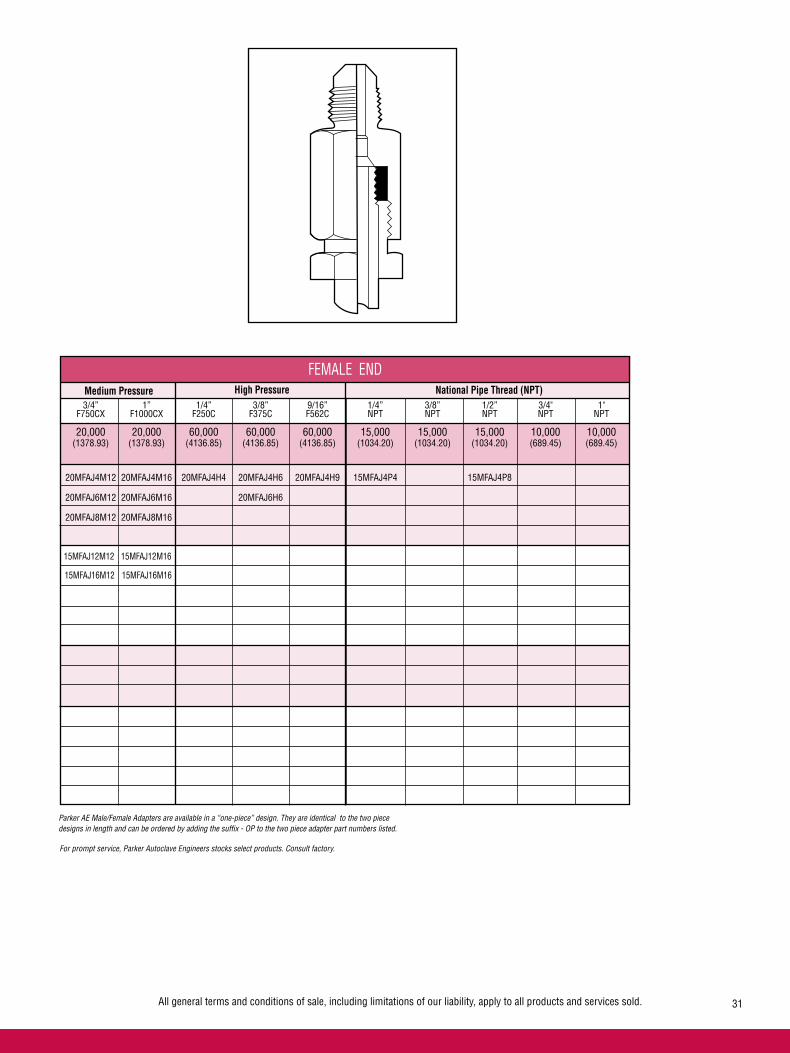
All general terms and conditions of sale, including limitations of our liability, apply to all products and services sold.
High Pressure National Pipe Thread (NPT)
FEMALE ENDMedium Pressure
15MFAJ12M12 15MFAJ12M16
31
3/4” 1” 1/4” 3/8” 9/16” 1/4” 3/8” 1/2” 3/4" 1" F750CX F1000CX F250C F375C F562C NPT NPT NPT NPT NPT
20,000 20,000 60,000 60,000 60,000 15,000 15,000 15,000 10,000 10,000 (1378.93) (1378.93) (4136.85) (4136.85) (4136.85) (1034.20) (1034.20) (1034.20) (689.45) (689.45)
20MFAJ4M12 20MFAJ4M16 20MFAJ4H4 20MFAJ4H6 20MFAJ4H9 15MFAJ4P4 15MFAJ4P8
20MFAJ6M12 20MFAJ6M16 20MFAJ6H6
20MFAJ8M12 20MFAJ8M16
15MFAJ16M12 15MFAJ16M16
Parker AE Male/Female Adapters are available in a “one-piece” design. They are identical to the two piece designs in length and can be ordered by adding the suffix - OP to the two piece adapter part numbers listed.
For prompt service, Parker Autoclave Engineers stocks select products. Consult factory.

Female End
Male End Fits this
Connection
CatalogNumber
Dimension inches (mm)
A Hex B
Adapters/Couplings - Male/Female JIC Adapters
B
AHex
32
JIC to Medium Pressure 1/4" JIC SF250CX 20MFAJ4M4 0.63 (15.9) 1.25 (31.8) 1/4" JIC SF375CX 20MFAJ4M6 0.75 (19.1) 1.50 (38.1) 1/4" JIC SF562CX 20MFAJ4M9 1.00 (25.4) 1.88 (47.8) 1/4" JIC SF750CX 20MFAJ4M12 1.38 (35.1) 2.13 (54.0) 1/4" JIC SF1000CX 20MFAJ4M16 1.75 (44.5) 2.75 (69.9) 3/8" JIC SF250CX 20MFAJ6M4 0.63 (15.9) 1.25 (31.8) 3/8" JIC SF375CX 20MFAJ6M6 0.75 (19.1) 1.44 (36.5) 3/8" JIC SF562CX 20MFAJ6M9 1.00 (25.4) 1.88 (47.8) 3/8" JIC SF750CX 20MFAJ6M12 1.38 (35.1) 2.13 (54.0) 3/8" JIC SF1000CX 20MFAJ6M16 1.75 (44.5) 2.62 (66.5)
1/2" JIC SF250CX 20MFAJ8M4 0.81 (20.6) 1.63 (41.3) 1/2" JIC SF375CX 20MFAJ8M6 0.81 (20.6) 1.75 (44.5) 1/2" JIC SF562CX 20MFAJ8M9 1.00 (25.4) 1.88 (47.8) 1/2" JIC SF750CX 20MFAJ8M12 1.38 (35.1) 2.25 (57.2) 1/2" JIC SF1000CX 20MFAJ8M16 1.75 (44.5) 2.75 (69.9)
3/4" JIC SF250CX 15MFAJ12M4 1.38 (35.1) 2.00 (50.8) 3/4" JIC SF375CX 15MFAJ12M6 1.38 (35.1) 2.00 (50.8) 3/4" JIC SF562CX 15MFAJ12M9 1.38 (35.1) 2.00 (50.8) 3/4" JIC SF750CX 15MFAJ12M12 1.38 (35.1) 2.25 (57.2) 3/4" JIC SF1000CX 15MFAJ12M16 1.75 (44.5) 3.25 (82.6)
1" JIC SF250CX 15MFAJ16M4 1.50 (38.1) 2.00 (50.8) 1" JIC SF375CX 15MFAJ16M6 1.50 (38.1) 2.00 (50.8) 1" JIC SF562CX 15MFAJ16M9 1.50 (38.1) 2.25 (57.2) 1" JIC SF750CX 15MFAJ16M12 1.38 (35.1) 2.62 (66.5) 1" JIC SF1000CX 15MFAJ16M16 1.75 (44.5) 3.25 (82.6)
JIC to High Pressure 1/4" JIC SF250C 20MFAJ4H4 0.75 (19.1) 1.38 (35.1) 1/4" JIC SF375C 20MFAJ4H6 1.00 (25.4) 1.50 (38.1) 1/4" JIC SF562C 20MFAJ4H9 1.38 (35.1) 2.00 (50.8) 3/8" JIC SF375C 20MFAJ6H6 1.00 (25.4) 1.50 (38.1)
JIC to NPT 1/4" JIC 1/4" NPT 15MFAJ4P4 0.94 (23.8) 1.50 (38.1) 1/4" JIC 1/2" NPT 15MFAJ4P8 1.19 (30.1) 1.88 (47.8)
Medium Pressure to JIC SF250CX 1/4" JIC 20MFAM4J4 0.75 (19.1) 1.56 (39.7) SF250CX 3/8" JIC 20MFAM4J6 0.81 (20.6) 1.50 (38.1) SF750CX 1/4" JIC 20MFAJ12J4 1.19 (30.1) 2.00 (50.8) High Pressure to JIC F250C 1/4" JIC 20MFAH4J4 0.75 (19.1) 1.50 (38.1)
NPT to JIC 3/8" NPT 3/8" JIC 15MFAP6J6 0.81 (20.6) 1.50 (38.1)
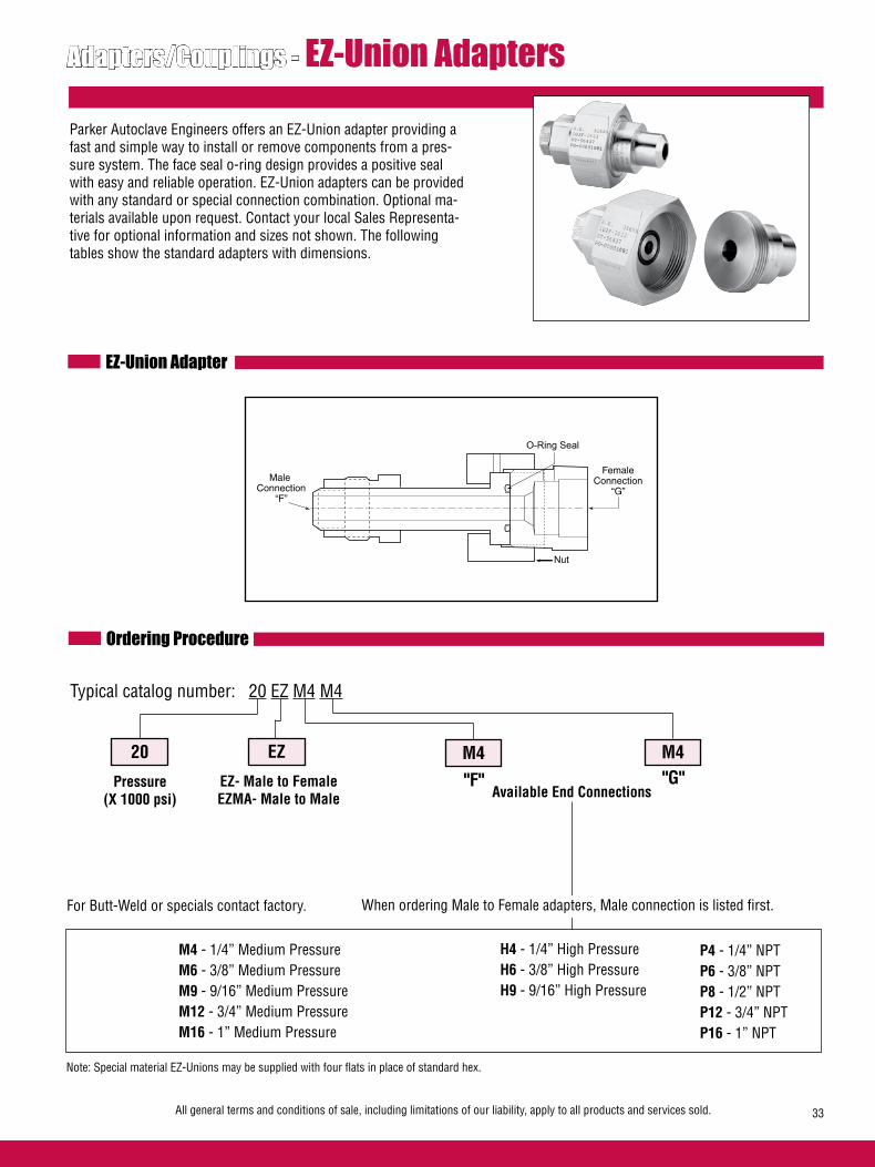
All general terms and conditions of sale, including limitations of our liability, apply to all products and services sold. 33
Adapters/Couplings - EZ-Union Adapters
Parker Autoclave Engineers offers an EZ-Union adapter providing a fast and simple way to install or remove components from a pres-sure system. The face seal o-ring design provides a positive seal with easy and reliable operation. EZ-Union adapters can be provided with any standard or special connection combination. Optional ma-terials available upon request. Contact your local Sales Representa-tive for optional information and sizes not shown. The following tables show the standard adapters with dimensions.
EZ-Union Adapter
Ordering Procedure
Typical catalog number: 20 EZ M4 M4
20
Pressure(X 1000 psi)
EZ
Available End Connections
M4 - 1/4” Medium PressureM6 - 3/8” Medium PressureM9 - 9/16” Medium PressureM12 - 3/4” Medium PressureM16 - 1” Medium Pressure
H4 - 1/4” High PressureH6 - 3/8” High PressureH9 - 9/16” High Pressure
P4 - 1/4” NPTP6 - 3/8” NPTP8 - 1/2” NPTP12 - 3/4” NPTP16 - 1” NPT
EZ- Male to FemaleEZMA- Male to Male
Note: Special material EZ-Unions may be supplied with four flats in place of standard hex.
M4 M4
"F" "G"
For Butt-Weld or specials contact factory.
O-Ring Seal
Nut
Male Connection
“F”
FemaleConnection
“G”
When ordering Male to Female adapters, Male connection is listed first.

Catalog Number
Dimension inches (mm)
EZ-Union Male to Female Adapters
EZ-Union Male to Male Adapters
Note1: EZ-Unions are constructed from 316 SS and are supplied with a Viton o-ring as standard.
Note 2: Gland and collar supplied with medium and high pressure connections.
Maximum pressure rating is based on the lowest rating of any component. Actual working pressure may be determined by tubing pressure rating, if lower.
Note: For pressure rating see ordering procedure.All Dimensions for reference only and subject to change.
FFor prompt service, Parker Autoclave Engineers stocks select products. Consult factory.
All general terms and conditions of sale, including limitations of our liability, apply to all products and services sold.34
AB
E
Male Connection
“F”
D
CC
Female Connection
“G”
E Min OpeningD HexBA C HexFemale
"G" ConnectionPressure
Rating psi (bar)
Catalog Number
Dimension inches (mm)
E Min OpeningD HexBA C HexPressure
Rating psi (bar)
20EZMAH4H6 M250C M375C 20,000 (1379) 5.94 (150.88) 3.56 (90.42) 1.00 (25.40) 0.81 (20.57) 0.09 (2.29) 10EZMAP12M12 SM750CX20 3/4" NPT 10,000 (690) 6.50 (165.10) 3.25 (82.55) 1.75 (44.45) 0.87 (22.05)* 0.44 (11.13)
*across flats
Male"F" Connection
Male"G" Connection
Male"F" Connection
A
B
E
C
D
Male Connection
“F”Male
Connection“G”
20EZM4M4 SM250CX20 SF250CX20 20,000 (1379) 3.13 (79.50) 1.00 (25.40) 1.00 (25.40) 0.81 (20.57) 0.109 (2.77) 10EZM9M9 SM562CX20 SF562CX20 10,000 (690) 4.63 (117.60) 1.63 (41.40) 1.75 (44.45) 1.38 (34.93) 0.31 (7.92) 10EZM12M12 SM750CX20 SF750CX20 10,000 (690) 4.63 (117.60) 1.38 (35.05) 1.75 (44.45) 1.50 (38.10) 0.44 (11.13) 10EZM16M16 SM1000CX20 SF1000CX20 10,000 (690) 6.44 (163.58) 2.31 (58.67) 1.75 (44.45) 1.75 (44.45) 0.56 (14.27) 10EZP12M12 3/4" NPT SF750CX20 10,000 (690) 4.63 (117.60) 1.38 (35.05) 1.75 (44.45) 1.50 (38.10) 0.44 (11.13) 10EZM16P8 SM1000CX20 1/2" NPT 10,000 (690) 5.38 (136.65) 1.25 (31.75) 1.75 (44.45) 1.38 (35.05) 0.56 (14.27)
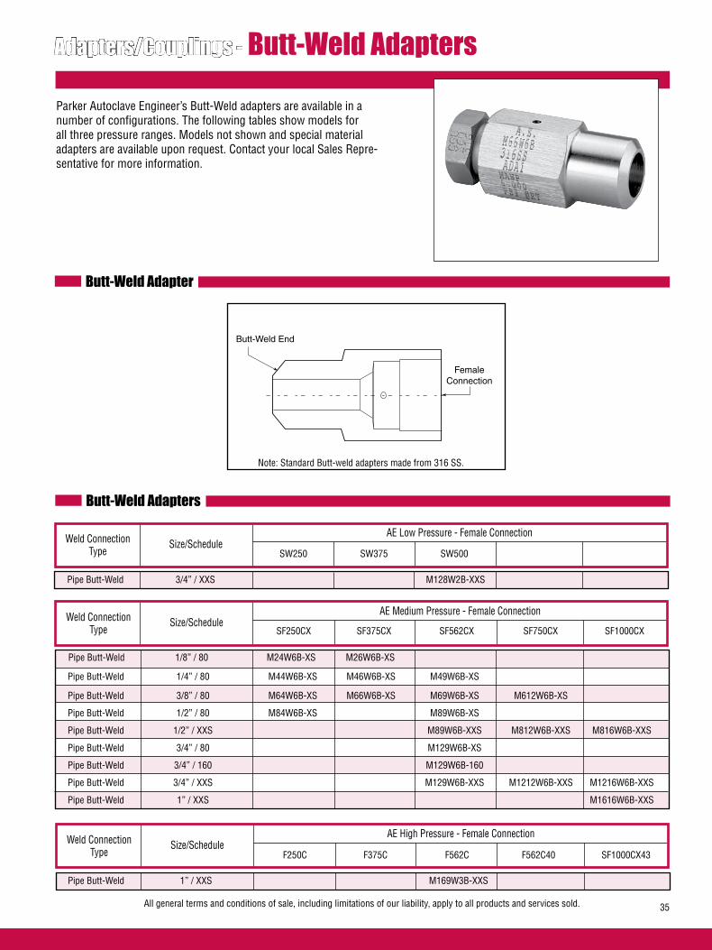
All general terms and conditions of sale, including limitations of our liability, apply to all products and services sold. 35
Adapters/Couplings - Butt-Weld Adapters
Parker Autoclave Engineer’s Butt-Weld adapters are available in a number of configurations. The following tables show models for all three pressure ranges. Models not shown and special material adapters are available upon request. Contact your local Sales Repre-sentative for more information.
Butt-Weld Adapter
Butt-Weld Adapters
Butt-Weld End
FemaleConnection
Size/ScheduleWeld Connection Type
AE Low Pressure - Female Connection
Pipe Butt-Weld 3/4” / XXS M128W2B-XXS
SW250 SW375 SW500
Size/ScheduleWeld Connection Type
AE Medium Pressure - Female Connection
SF250CX SF375CX SF562CX SF750CX SF1000CX
Pipe Butt-Weld 1/4” / 80 M44W6B-XS M46W6B-XS M49W6B-XS
Pipe Butt-Weld 3/8” / 80 M64W6B-XS M66W6B-XS M69W6B-XS M612W6B-XS
Pipe Butt-Weld 1/2” / 80 M84W6B-XS M89W6B-XS
Pipe Butt-Weld 1/2” / XXS M89W6B-XXS M812W6B-XXS M816W6B-XXS
Pipe Butt-Weld 3/4” / 80 M129W6B-XS
Pipe Butt-Weld 3/4” / 160 M129W6B-160
Pipe Butt-Weld 3/4” / XXS M129W6B-XXS M1212W6B-XXS M1216W6B-XXS
Pipe Butt-Weld 1” / XXS M1616W6B-XXS
Size/ScheduleWeld Connection Type
AE High Pressure - Female Connection
Pipe Butt-Weld 1” / XXS M169W3B-XXS
F250C F375C F562C F562C40 SF1000CX43
Note: Standard Butt-weld adapters made from 316 SS.
Pipe Butt-Weld 1/8” / 80 M24W6B-XS M26W6B-XS
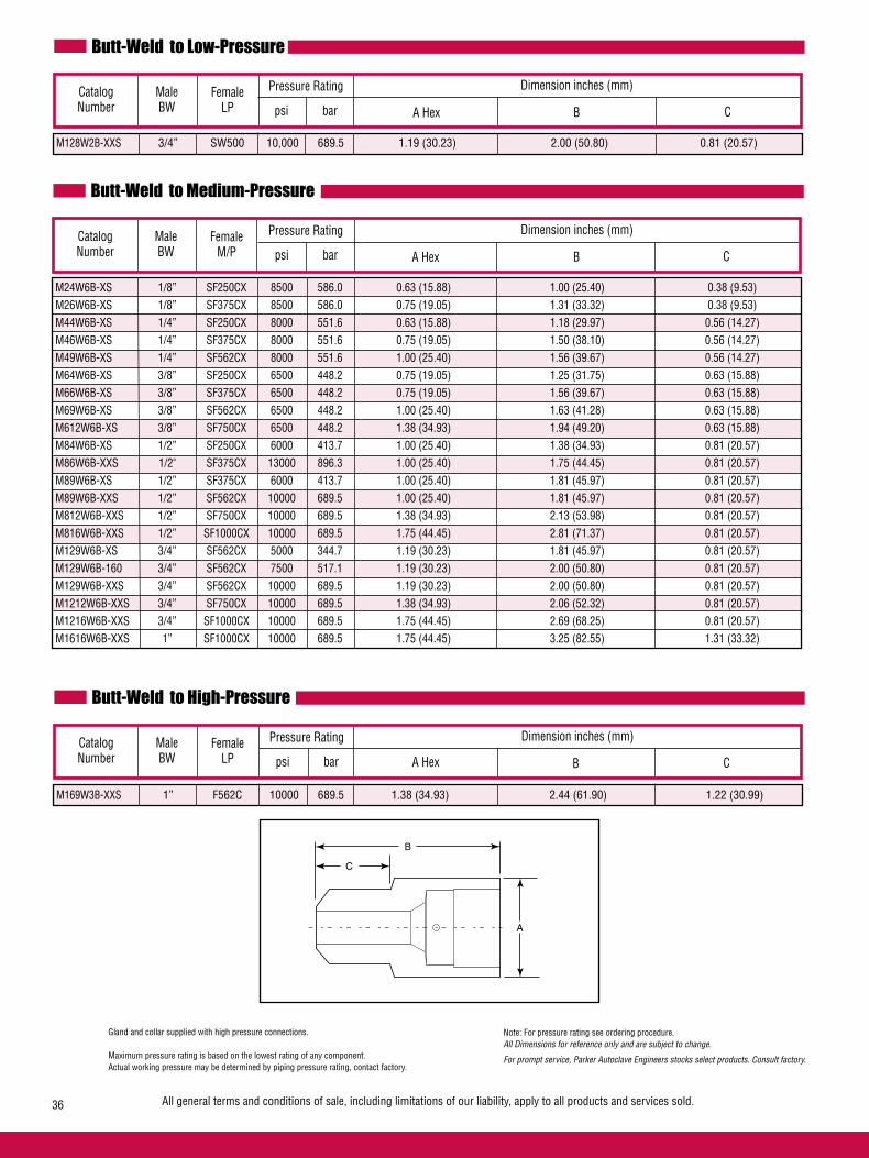
Butt-Weld to Low-Pressure
Male BW
Catalog Number
FemaleLP
Dimension inches (mm)
A Hex
M128W2B-XXS 3/4” SW500 10,000 689.5 1.19 (30.23) 2.00 (50.80) 0.81 (20.57)
B C
Butt-Weld to Medium-Pressure
Male BW
Catalog Number
Dimension inches (mm)
A Hex B C
Butt-Weld to High-Pressure
Male BW
Catalog Number
FemaleLP
Dimension inches (mm)
A Hex
M169W3B-XXS 1” F562C 10000 689.5 1.38 (34.93) 2.44 (61.90) 1.22 (30.99)
B C
B
C
A
Gland and collar supplied with high pressure connections.
Maximum pressure rating is based on the lowest rating of any component. Actual working pressure may be determined by piping pressure rating, contact factory.
Note: For pressure rating see ordering procedure.All Dimensions for reference only and are subject to change.
For prompt service, Parker Autoclave Engineers stocks select products. Consult factory.
All general terms and conditions of sale, including limitations of our liability, apply to all products and services sold.36
FemaleM/P
Pressure Rating
psi bar
Pressure Rating
psi bar
Pressure Rating
psi bar
M24W6B-XS 1/8” SF250CX 8500 586.0 0.63 (15.88) 1.00 (25.40) 0.38 (9.53) M26W6B-XS 1/8” SF375CX 8500 586.0 0.75 (19.05) 1.31 (33.32) 0.38 (9.53) M44W6B-XS 1/4” SF250CX 8000 551.6 0.63 (15.88) 1.18 (29.97) 0.56 (14.27) M46W6B-XS 1/4” SF375CX 8000 551.6 0.75 (19.05) 1.50 (38.10) 0.56 (14.27) M49W6B-XS 1/4” SF562CX 8000 551.6 1.00 (25.40) 1.56 (39.67) 0.56 (14.27) M64W6B-XS 3/8” SF250CX 6500 448.2 0.75 (19.05) 1.25 (31.75) 0.63 (15.88) M66W6B-XS 3/8” SF375CX 6500 448.2 0.75 (19.05) 1.56 (39.67) 0.63 (15.88) M69W6B-XS 3/8” SF562CX 6500 448.2 1.00 (25.40) 1.63 (41.28) 0.63 (15.88) M612W6B-XS 3/8” SF750CX 6500 448.2 1.38 (34.93) 1.94 (49.20) 0.63 (15.88) M84W6B-XS 1/2” SF250CX 6000 413.7 1.00 (25.40) 1.38 (34.93) 0.81 (20.57) M86W6B-XXS 1/2" SF375CX 13000 896.3 1.00 (25.40) 1.75 (44.45) 0.81 (20.57) M89W6B-XS 1/2” SF375CX 6000 413.7 1.00 (25.40) 1.81 (45.97) 0.81 (20.57) M89W6B-XXS 1/2” SF562CX 10000 689.5 1.00 (25.40) 1.81 (45.97) 0.81 (20.57) M812W6B-XXS 1/2” SF750CX 10000 689.5 1.38 (34.93) 2.13 (53.98) 0.81 (20.57) M816W6B-XXS 1/2” SF1000CX 10000 689.5 1.75 (44.45) 2.81 (71.37) 0.81 (20.57) M129W6B-XS 3/4” SF562CX 5000 344.7 1.19 (30.23) 1.81 (45.97) 0.81 (20.57) M129W6B-160 3/4” SF562CX 7500 517.1 1.19 (30.23) 2.00 (50.80) 0.81 (20.57) M129W6B-XXS 3/4” SF562CX 10000 689.5 1.19 (30.23) 2.00 (50.80) 0.81 (20.57) M1212W6B-XXS 3/4” SF750CX 10000 689.5 1.38 (34.93) 2.06 (52.32) 0.81 (20.57) M1216W6B-XXS 3/4” SF1000CX 10000 689.5 1.75 (44.45) 2.69 (68.25) 0.81 (20.57) M1616W6B-XXS 1” SF1000CX 10000 689.5 1.75 (44.45) 3.25 (82.55) 1.31 (33.32)
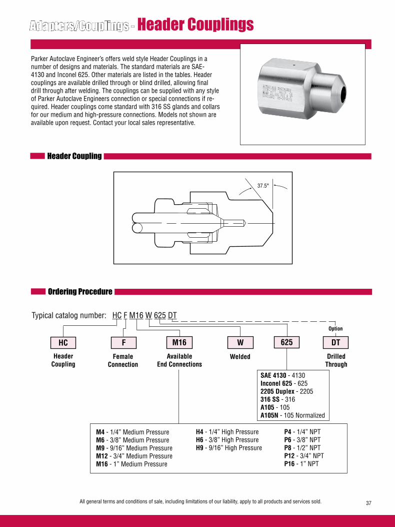
All general terms and conditions of sale, including limitations of our liability, apply to all products and services sold. 37
Adapters/Couplings - Header Couplings
Parker Autoclave Engineer’s offers weld style Header Couplings in a number of designs and materials. The standard materials are SAE-4130 and Inconel 625. Other materials are listed in the tables. Header couplings are available drilled through or blind drilled, allowing final drill through after welding. The couplings can be supplied with any style of Parker Autoclave Engineers connection or special connections if re-quired. Header couplings come standard with 316 SS glands and collars for our medium and high-pressure connections. Models not shown are available upon request. Contact your local sales representative.
Header Coupling
Ordering Procedure
Typical catalog number: HC F M16 W 625 DT
HC
HeaderCoupling
F M16 W
Available End Connections
M4 - 1/4” Medium PressureM6 - 3/8” Medium PressureM9 - 9/16” Medium PressureM12 - 3/4” Medium PressureM16 - 1” Medium Pressure
H4 - 1/4” High PressureH6 - 3/8” High PressureH9 - 9/16” High Pressure
FemaleConnection
625 DT
Welded DrilledThrough
SAE 4130 - 4130Inconel 625 - 6252205 Duplex - 2205316 SS - 316A105 - 105A105N - 105 Normalized
Option
P4 - 1/4” NPTP6 - 3/8” NPTP8 - 1/2” NPTP12 - 3/4” NPTP16 - 1” NPT
37.5°

Material
Catalog Number
Pressurepsi (bar)
Dimension inches (mm)FemaleM/P A Flats
Female Medium-Pressure Header Coupling Blind End
B C
Gland and collar supplied with high pressure connections. Maximum pressure rating is based on the lowest rating of any component. Actual working pressure may be determined by tubing pressure rating, if lower.
All Dimensions for reference only and are subject to change.
For prompt service, Parker Autoclave Engineers stocks select products. Consult factory.
All general terms and conditions of sale, including limitations of our liability, apply to all products and services sold.38
E
Material
Catalog Number
Pressurepsi (bar)
Dimension inches (mm)FemaleH/P A Flats
HCFH9W316 316SS 30,000 (2068) F562C 1.50 (38.10) 2.31 (58.67) 1.19 (30.18) 1.31 (33.27) 0.19 (4.75) HCFH9W4130 SAE-4130 30,000 (2068) F562C 1.50 (38.10) 2.31 (58.67) 1.19 (30.18) 1.31 (33.27) 0.19 (4.75) HCFH9W625 Inconel 625 30,000 (2068) F562C 1.50 (38.10) 2.31 (58.67) 1.19 (30.18) 1.31 (33.27) 0.19 (4.75) HCFH16W4130 SAE-4130 20,000 (1379) F1000C43 1.75 (44.45) 3.00 (76.20) 1.05 (26.59) 1.32 (33.53) 0.44 (11.10) HCFH16W625 Inconel 625 22,000 (1551) F1000C43 1.75 (44.45) 3.00 (76.20) 1.05 (26.59) 1.32 (33.53) 0.44 (11.10)
Female High-Pressure Header Coupling Blind End
B C E
A
B
C
E
D
D
D
HCFM12W316 316 SS 10,000 (690) SF750CX20 1.75 (44.45) 3.00 (76.2) 1.05 (26.7) 1.32 (33.5) 0.44 (11.2) HCFM12W105 SA-105 10,000 (690) SF750CX20 1.75 (44.45) 3.00 (76.2) 1.05 (26.7) 1.32 (33.5) 0.44 (11.2) HCFM12W4130 SAE-4130 20,000 (1379) SF750CX20 1.75 (44.45) 3.00 (76.2) 1.05 (26.7) 1.32 (33.5) 0.44 (11.2) HCFM12W2205 2205 Duplex 15,000 (1034) SF750CX20 1.75 (44.45) 3.00 (76.2) 1.05 (26.7) 1.32 (33.5) 0.44 (11.2) HCFM16W316 316 SS 10,000 (690) SF1000CX20 1.75 (44.45) 2.62 (66.55) 1.00 (25.40) 1.38 (34.93) 0.56 (14.27) HCFM16W2205 2205 Duplex 15,000 (1034) SF1000CX20 1.75 (44.45) 3.00 (76.2) 1.05 (26.7) 1.31 (33.27) 0.56 (14.27)
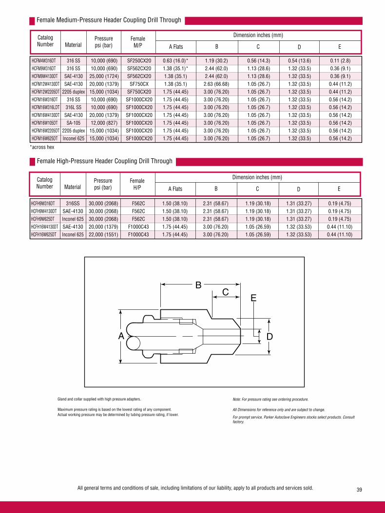
Material
Catalog Number
Pressurepsi (bar)
Dimension inches (mm)FemaleM/P A Flats
Female Medium-Pressure Header Coupling Drill Through
B C
All general terms and conditions of sale, including limitations of our liability, apply to all products and services sold. 39
E
Female High-Pressure Header Coupling Drill Through
A
BC
E
D
Gland and collar supplied with high pressure adapters. Maximum pressure rating is based on the lowest rating of any component. Actual working pressure may be determined by tubing pressure rating, if lower.
Note: For pressure rating see ordering procedure.
All Dimensions for reference only and are subject to change.
For prompt service, Parker Autoclave Engineers stocks select products. Consult factory.
D
Material
Catalog Number
Pressurepsi (bar)
Dimension inches (mm)FemaleH/P A Flats B C ED
HCFH9W316DT 316SS 30,000 (2068) F562C 1.50 (38.10) 2.31 (58.67) 1.19 (30.18) 1.31 (33.27) 0.19 (4.75) HCFH9W4130DT SAE-4130 30,000 (2068) F562C 1.50 (38.10) 2.31 (58.67) 1.19 (30.18) 1.31 (33.27) 0.19 (4.75) HCFH9W625DT Inconel 625 30,000 (2068) F562C 1.50 (38.10) 2.31 (58.67) 1.19 (30.18) 1.31 (33.27) 0.19 (4.75) HCFH16W4130DT SAE-4130 20,000 (1379) F1000C43 1.75 (44.45) 3.00 (76.20) 1.05 (26.59) 1.32 (33.53) 0.44 (11.10) HCFH16W625DT Inconel 625 22,000 (1551) F1000C43 1.75 (44.45) 3.00 (76.20) 1.05 (26.59) 1.32 (33.53) 0.44 (11.10)
HCFM4W316DT 316 SS 10,000 (690) SF250CX20 0.63 (16.0)* 1.19 (30.2) 0.56 (14.3) 0.54 (13.6) 0.11 (2.8) HCFM9W316DT 316 SS 10,000 (690) SF562CX20 1.38 (35.1)* 2.44 (62.0) 1.13 (28.6) 1.32 (33.5) 0.36 (9.1) HCFM9W4130DT SAE-4130 25,000 (1724) SF562CX20 1.38 (35.1) 2.44 (62.0) 1.13 (28.6) 1.32 (33.5) 0.36 (9.1) HCFM12W4130DT SAE-4130 20,000 (1379) SF750CX 1.38 (35.1) 2.63 (66.68) 1.05 (26.7) 1.32 (33.5) 0.44 (11.2) HCFM12W2205DT 2205 duplex 15,000 (1034) SF750CX20 1.75 (44.45) 3.00 (76.20) 1.05 (26.7) 1.32 (33.5) 0.44 (11.2) HCFM16W316DT 316 SS 10,000 (690) SF1000CX20 1.75 (44.45) 3.00 (76.20) 1.05 (26.7) 1.32 (33.5) 0.56 (14.2) HCFM16W316LDT 316L SS 10,000 (690) SF1000CX20 1.75 (44.45) 3.00 (76.20) 1.05 (26.7) 1.32 (33.5) 0.56 (14.2) HCFM16W4130DT SAE-4130 20,000 (1379) SF1000CX20 1.75 (44.45) 3.00 (76.20) 1.05 (26.7) 1.32 (33.5) 0.56 (14.2) HCFM16W105DT SA-105 12,000 (827) SF1000CX20 1.75 (44.45) 3.00 (76.20) 1.05 (26.7) 1.32 (33.5) 0.56 (14.2) HCFM16W2205DT 2205 duplex 15,000 (1034) SF1000CX20 1.75 (44.45) 3.00 (76.20) 1.05 (26.7) 1.32 (33.5) 0.56 (14.2) HCFM16W625DT Inconel 625 15,000 (1034) SF1000CX20 1.75 (44.45) 3.00 (76.20) 1.05 (26.7) 1.32 (33.5) 0.56 (14.2) *across hex
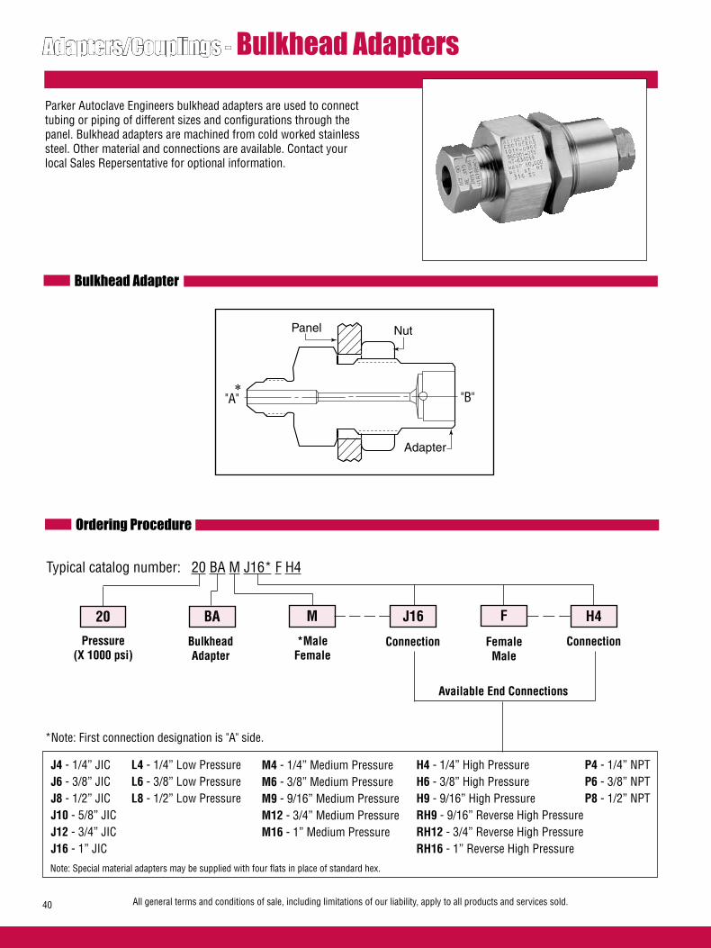
All general terms and conditions of sale, including limitations of our liability, apply to all products and services sold.40
Adapters/Couplings - Bulkhead Adapters
Parker Autoclave Engineers bulkhead adapters are used to connect tubing or piping of different sizes and configurations through the panel. Bulkhead adapters are machined from cold worked stainless steel. Other material and connections are available. Contact your local Sales Repersentative for optional information.
Bulkhead Adapter
Ordering Procedure
Typical catalog number: 20 BA M J16* F H4
20
Pressure(X 1000 psi)
BA M J16
*MaleFemale
BulkheadAdapter
F H4
Connection Connection
Panel Nut
Adapter
FemaleMale
J4 - 1/4” JICJ6 - 3/8” JICJ8 - 1/2” JICJ10 - 5/8” JICJ12 - 3/4” JICJ16 - 1” JIC
L4 - 1/4” Low PressureL6 - 3/8” Low PressureL8 - 1/2” Low Pressure
M4 - 1/4” Medium PressureM6 - 3/8” Medium PressureM9 - 9/16” Medium PressureM12 - 3/4” Medium PressureM16 - 1” Medium Pressure
H4 - 1/4” High PressureH6 - 3/8” High PressureH9 - 9/16” High PressureRH9 - 9/16” Reverse High PressureRH12 - 3/4” Reverse High Pressure RH16 - 1” Reverse High Pressure
P4 - 1/4” NPTP6 - 3/8” NPTP8 - 1/2” NPT
Available End Connections
Note: Special material adapters may be supplied with four flats in place of standard hex.
"A" "B"
*Note: First connection designation is "A" side.
*
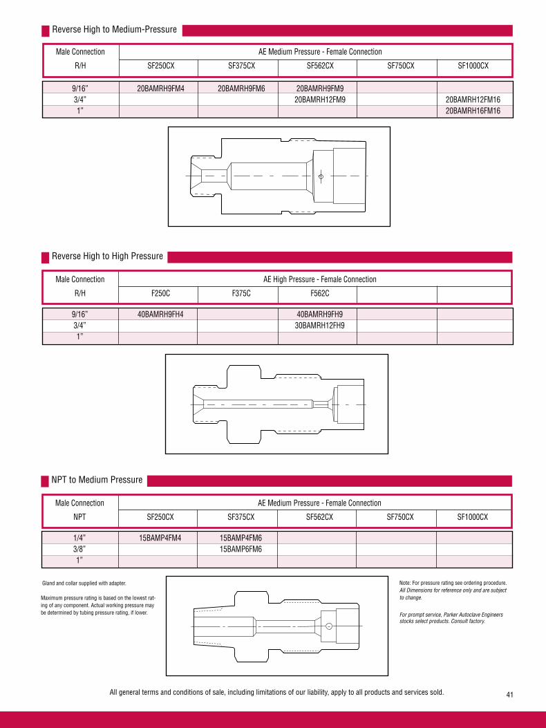
Male Connection AE Medium Pressure - Female Connection
R/H SF250CX SF375CX SF562CX SF750CX SF1000CX
Reverse High to Medium-Pressure
9/16” 20BAMRH9FM4 20BAMRH9FM6 20BAMRH9FM9 3/4” 20BAMRH12FM9 20BAMRH12FM16 1” 20BAMRH16FM16
Male Connection AE High Pressure - Female Connection
R/H F250C F375C F562C
Reverse High to High Pressure
9/16” 40BAMRH9FH4 40BAMRH9FH9 3/4” 30BAMRH12FH9 1”
Male Connection AE Medium Pressure - Female Connection
NPT SF250CX SF375CX SF562CX SF750CX SF1000CX
NPT to Medium Pressure
1/4” 15BAMP4FM4 15BAMP4FM6 3/8” 15BAMP6FM6 1”
All general terms and conditions of sale, including limitations of our liability, apply to all products and services sold. 41
Gland and collar supplied with adapter.
Maximum pressure rating is based on the lowest rat-ing of any component. Actual working pressure may be determined by tubing pressure rating, if lower.
Note: For pressure rating see ordering procedure.All Dimensions for reference only and are subject to change.
For prompt service, Parker Autoclave Engineers stocks select products. Consult factory.
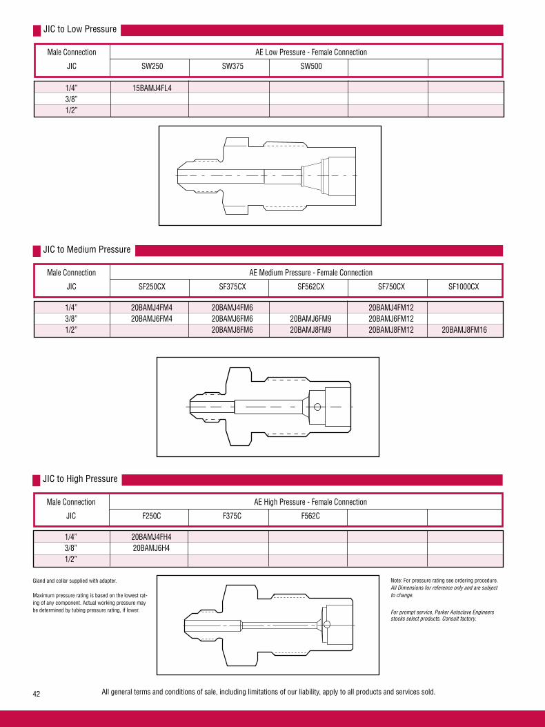
All general terms and conditions of sale, including limitations of our liability, apply to all products and services sold.42
Male Connection AE Low Pressure - Female Connection
JIC SW250 SW375 SW500
JIC to Low Pressure
1/4” 15BAMJ4FL4 3/8” 1/2”
Male Connection AE Medium Pressure - Female Connection
JIC SF250CX SF375CX SF562CX SF750CX SF1000CX
JIC to Medium Pressure
1/4” 20BAMJ4FM4 20BAMJ4FM6 20BAMJ4FM12 3/8” 20BAMJ6FM4 20BAMJ6FM6 20BAMJ6FM9 20BAMJ6FM12 1/2” 20BAMJ8FM6 20BAMJ8FM9 20BAMJ8FM12 ě20BAMJ8FM16
Male Connection AE High Pressure - Female Connection
JIC F250C F375C F562C
JIC to High Pressure
1/4” 20BAMJ4FH4 3/8” 20BAMJ6H4 1/2”
Gland and collar supplied with adapter.
Maximum pressure rating is based on the lowest rat-ing of any component. Actual working pressure may be determined by tubing pressure rating, if lower.
Note: For pressure rating see ordering procedure.All Dimensions for reference only and are subject to change.
For prompt service, Parker Autoclave Engineers stocks select products. Consult factory.

All general terms and conditions of sale, including limitations of our liability, apply to all products and services sold. 43
Male R/H
Catalog Number
FemaleM/P
Dimension inches (mm)
A Panel Hole
Reverse High Pressure to Medium Pressure
B C D Max E Hex
Male R/H
Catalog Number
FemaleH/P
Dimension inches (mm)
A Panel Hole
40BAMRH9FH4 9/16” F250C 0.94 (23.88) 2.50 (63.50) 1.00 (25.40) 0.38 (9.65) 1.00 (25.40) 40BAMRH9FH9 9/16” F562C 1.69 (42.85) 3.38 (85.85) 1.50 (38.10) 0.38 (9.65) 1.88 (47.75) 30BAMRH12FH9 3/4” F562C 1.69 (42.85) 3.50 (88.90) 1.62 (41.15) 0.38 (9.65) 1.88 (47.75)
Reverse High Pressure to High Pressure
B C D Max E Hex
Male NPT
Catalog Number
FemaleM/P
Dimension inches (mm)
A Panel Hole
Pipe to Medium Pressure
B C E Hex
Gland and collar supplied with adapter.
Maximum pressure rating is based on the lowest rating of any component. Actual working pressure may be determined by tubing pressure rating, if lower.
Note: For pressure rating see ordering procedure.All Dimensions for reference only and are subject to change.
For prompt service, Parker Autoclave Engineers stocks select products. Consult factory.
EHex
C DMaximum
APanel HoleDrill Size
B
D Max
20BAMRH9FM4 9/16” SF250CX 0.81 (20.62) 2.56 (65.0) 1.22 (31.0) 0.38 (9.65) 1.00 (25.40)
20BAMRH9FM6 9/16” SF375CX 0.94 (23.88) 2.63 (66.80) 1.13 (28.70) 0.38 (9.65) 1.00 (25.40)
20BAMRH9FM9 9/16” SF562CX 1.13 (28.58) 3.00 (76.20) 1.28 (32.51) 0.38 (9.65) 1.38 (34.93)
20BAMRH12FM9 3/4” SF562CX 1.13 (28.58) 3.13 (79.50) 1.41 (35.81) 0.38 (9.65) 1.38 (34.93)
20BAMRH12FM16 3/4” SF1000CX 1.94 (49.28) 4.26 (108.20) 2.13 (54.10) 0.38 (9.65) 2.13 (54.10)
20BAMRH16FM16 1” SF1000CX 1.94 (49.28) 4.41 (112.01) 2.28 (57.91) 0.38 (9.65) 2.13 (54.10)
15BAMP4FM4 1/4” SF250CX 0.81 (20.62) 2.56 (65.02) 1.22 (31.01) 0.38 (9.65) 1.00 (25.40)
15BAMP4FM6 1/4” SF375CX 0.94 (23.88) 2.69 (68.33) 1.31 (33.35) 0.38 (9.65) 1.00 (25.40)
15BAMP6FM6 3/8” SF375CX 0.94 (23.88) 2.75 (69.85) 1.25 (31.75) 0.38 (9.65) 1.00 (25.40)

All general terms and conditions of sale, including limitations of our liability, apply to all products and services sold.44
Male JIC
Catalog Number
FemaleLP
Dimension inches (mm)
A Panel Hole
15BAMJ4FL4 1/4” SW250 0.94 (23.88) 2.29 (58.04) 0.91 (23.11) 0.38 (9.65) 1.00 (25.40)
JIC to Low Pressure
B C E Hex
Male JIC
Catalog Number
FemaleMP
Dimension inches (mm)
A Panel Hole
JIC to Medium Pressure
B C E Hex
Male JIC
Catalog Number
FemaleHP
Dimension inches (mm)
A Panel Hole
JIC to High Pressure
B C E Hex
Gland and collar supplied with adapter.
Maximum pressure rating is based on the lowest rating of any component. Actual working pressure may be determined by tubing pressure rating, if lower.
Note: For pressure rating see ordering procedure.All Dimensions for reference only and are subject to change.
For prompt service, Parker Autoclave Engineers stocks select products. Consult factory.
D Max
D Max
D Max
*Dimension across flats
20BAMJ4FM4 1/4” SF250CX 0.81 (20.62) 2.25 (57.15) 0.91 (23.11) 0.38 (9.65) 1.00 (25.40) 20BAMJ4FM6 1/4” SF375CX 0.81 (20.62) 2.44 (61.93) 0.94 (23.88) 0.38 (9.65) 1.00 (25.40) 20BAMJ4FM12 1/4” SF750CX 1.69 (42.85) 2.94 (74.68) 1.22 (31.0) 0.38 (9.65) 1.88 (47.75) 20BAMJ6FM4 3/8” SF250CX 0.81 (20.62) 2.25 (57.15) 0.91 (23.11) 0.38 (9.65) 1.00 (25.40) 20BAMJ6FM6 3/8” SF375CX 0.94 (23.88) 2.44 (61.98) 0.94 (23.88) 0.38 (9.65) 1.00 (25.40) 20BAMJ6FM9 3/8” SF562CX 1.13 (28.58) 2.75 (69.85) 1.16 (29.46) 0.38 (9.65) 1.38 (34.93) 20BAMJ6FM12 3/8” SF750CX 1.69 (42.85) 2.94 (74.68) 1.22 (31.0) 0.38 (9.65) 1.88 (47.75) 20BAMJ8FM6 1/2” SF375CX 0.81 (20.62) 2.53 (64.26) 1.03 (26.16) 0.38 (9.65) 1.00 (25.40) 20BAMJ8FM9 1/2” SF562CX 1.13 (28.58) 3.00 (76.20) 1.41 (35.69) 0.38 (9.65) 1.38 (34.93) 20BAMJ8FM12 1/2” SF750CX 1.69 (42.85) 3.13 (79.38) 1.41 (35.69) 0.38 (9.65) 1.88 (47.75) 20BAMJ8FM16 1/2” SF1000CX 1.94 (49.20) 4.36 (110.72) 2.23 (56.62) 0.50 (12.70) 1.87 (47.50*)
20BAMJ4FH4 1/4” F250C 0.94 (23.80) 2.44 (61.90) 1.06 (26.97) 0.38 (9.65) 1.00 (25.40) 20BAMJ6FH4 3/8” F250C 0.94 (23.80) 2.47 (62.74) 1.09 (27.79) 0.38 (9.65) 1.00 (25.40)
EHex
C DMaximum
APanel HoleDrill Size
B

Adapters/Couplings - SAE O-Ring AdaptersParker Autoclave Engineers also offers a line of components that assist in adapting into and out of specialized connections with Parker Autoclave Engineers products. Along with the adapters shown, Parker Autoclave Engineers can provide other special adapters to fill your requirements. Contact your local Sales representative for information.
AE Low, Medium and High Medium Pressure (Female) SAE/MS Male
MC240 (SAE/MS Straight thread Boss)
AE Medium Pressure (Female) SAE/MS Thread Size (inches) SF250CX SF375CX SF562CX SF750CX SF1000CX
ConnectionType
MC240(SAE/MS)
For additional information contact your local sales representative.
All general terms and conditions of sale, including limitations of our liability, apply to all products and services sold. 45
MC240
SAE/MS
O-Ring
Note: O-rings are standard Buna-N.
10,000 psi (690 bar) operating pressure.
SAE/MS Thread Size (inches) W125 SW250 SW 375 SW500
AE Low Pressure (Female)Connection
Type
MC240(SAE/MS)
5/16-24 7/16-20 M44MC2B M46MC2B 9/16-18 3/4-16
AE High Pressure (Female) SAE/MS Thread Size (inches) F250C F375C F562C
ConnectionType
MC240(SAE/MS)
5/16-24 7/16-20 M44MC3B M46MC3B 9/16-18 M64MC3B M66MC3B 3/4-16
5/16-24 M24MC6B M26MC6B 7/16-20 M44MC6B M46MC6B M49MC6B 9/16-18 M64MC6B M66MC6B M69MC6B 3/4-16 M86MC6B M89MC6B M812MC6B 7/8-14 M1012MC6B M1016MC6B 1-1/16-12 M126MC6B M1212MC6B M1216MC6B 1-5/16-12 M1616MC6B
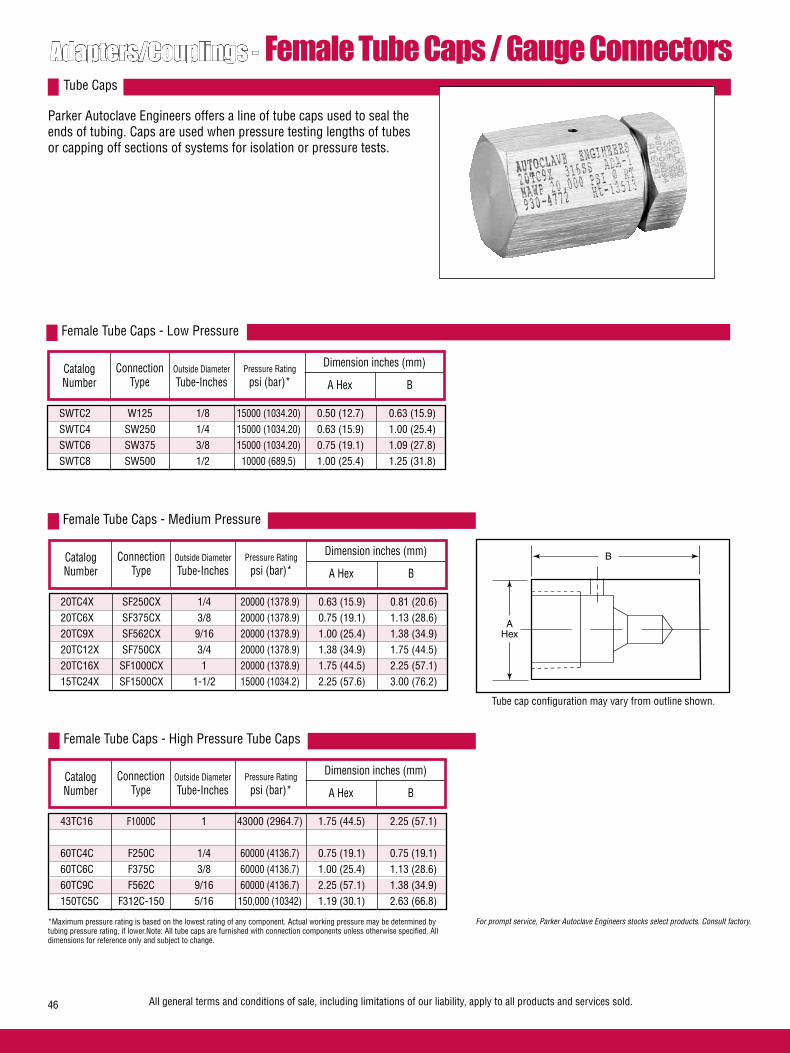
Adapters/Couplings - Female Tube Caps / Gauge ConnectorsParker Autoclave Engineers offers a line of tube caps used to seal the ends of tubing. Caps are used when pressure testing lengths of tubes or capping off sections of systems for isolation or pressure tests.
Tube Caps
Connection Type
Catalog Number
Outside DiameterTube-Inches
Dimension inches (mm)
A Hex B
Female Tube Caps - Low Pressure
Pressure Ratingpsi (bar)*
Connection Type
Catalog Number
Outside DiameterTube-Inches
Dimension inches (mm)
A Hex B
Female Tube Caps - Medium Pressure
Pressure Ratingpsi (bar)*
AHex
B
All general terms and conditions of sale, including limitations of our liability, apply to all products and services sold.46
Connection Type
Catalog Number
Outside DiameterTube-Inches
Dimension inches (mm)
A Hex B
Female Tube Caps - High Pressure Tube Caps
Pressure Ratingpsi (bar)*
*Maximum pressure rating is based on the lowest rating of any component. Actual working pressure may be determined by tubing pressure rating, if lower.Note: All tube caps are furnished with connection components unless otherwise specified. All dimensions for reference only and subject to change.
For prompt service, Parker Autoclave Engineers stocks select products. Consult factory.
Tube cap configuration may vary from outline shown.
SWTC2 W125 1/8 15000 (1034.20) 0.50 (12.7) 0.63 (15.9) SWTC4 SW250 1/4 15000 (1034.20) 0.63 (15.9) 1.00 (25.4) SWTC6 SW375 3/8 15000 (1034.20) 0.75 (19.1) 1.09 (27.8) SWTC8 SW500 1/2 10000 (689.5) 1.00 (25.4) 1.25 (31.8)
20TC4X SF250CX 1/4 20000 (1378.9) 0.63 (15.9) 0.81 (20.6) 20TC6X SF375CX 3/8 20000 (1378.9) 0.75 (19.1) 1.13 (28.6) 20TC9X SF562CX 9/16 20000 (1378.9) 1.00 (25.4) 1.38 (34.9) 20TC12X SF750CX 3/4 20000 (1378.9) 1.38 (34.9) 1.75 (44.5) 20TC16X SF1000CX 1 20000 (1378.9) 1.75 (44.5) 2.25 (57.1) 15TC24X SF1500CX 1-1/2 15000 (1034.2) 2.25 (57.6) 3.00 (76.2)
43TC16 F1000C 1 43000 (2964.7) 1.75 (44.5) 2.25 (57.1) 60TC4C F250C 1/4 60000 (4136.7) 0.75 (19.1) 0.75 (19.1) 60TC6C F375C 3/8 60000 (4136.7) 1.00 (25.4) 1.13 (28.6) 60TC9C F562C 9/16 60000 (4136.7) 2.25 (57.1) 1.38 (34.9) 150TC5C F312C-150 5/16 150,000 (10342) 1.19 (30.1) 2.63 (66.8)
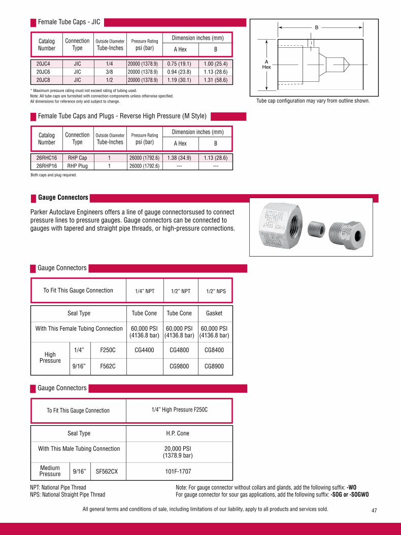
Gauge Connectors
1/4” NPT 1/2” NPT 1/2” NPS
With This Female Tubing Connection 60,000 PSI 60,000 PSI 60,000 PSI (4136.8 bar) (4136.8 bar) (4136.8 bar)
1/4” F250C CG4400 CG4800 CG8400
9/16” F562C CG9800 CG8900
HighPressure
To Fit This Gauge Connection
Seal Type H.P. Cone
Gauge Connectors
➧ 1/4” High Pressure F250C
With This Male Tubing Connection 20,000 PSI (1378.9 bar) ➧
MediumPressure 9/16” SF562CX 101F-1707
NPT: National Pipe Thread Note: For gauge connector without collars and glands, add the following suffix: -WONPS: National Straight Pipe Thread For gauge connector for sour gas applications, add the following suffix: -SOG or -SOGWO
All general terms and conditions of sale, including limitations of our liability, apply to all products and services sold. 47
Parker Autoclave Engineers offers a line of gauge connectorsused to connect pressure lines to pressure gauges. Gauge connectors can be connected to gauges with tapered and straight pipe threads, or high-pressure connections.
Gauge Connectors
Connection Type
Catalog Number
Outside DiameterTube-Inches
Dimension inches (mm)
A Hex B
Female Tube Caps - JIC
Pressure Ratingpsi (bar)
* Maximum pressure rating must not exceed rating of tubing used.Note: All tube caps are furnished with connection components unless otherwise specified. All dimensions for reference only and subject to change.
AHex
B
Tube cap configuration may vary from outline shown.
Adapters/Couplings - Female Tube Caps / Gauge Connectors
20JC4 JIC 1/4 20000 (1378.9) 0.75 (19.1) 1.00 (25.4) 20JC6 JIC 3/8 20000 (1378.9) 0.94 (23.8) 1.13 (28.6) 20JC8 JIC 1/2 20000 (1378.9) 1.19 (30.1) 1.31 (58.6)
To Fit This Gauge Connection
Seal Type Tube Cone Tube Cone Gasket
Connection Type
Catalog Number
Outside DiameterTube-Inches
Dimension inches (mm)
A Hex B
Female Tube Caps and Plugs - Reverse High Pressure (M Style)
Pressure Ratingpsi (bar)
Both caps and plug required.
26RHC16 RHP Cap 1 26000 (1792.6) 1.38 (34.9) 1.13 (28.6) 26RHP16 RHP Plug 1 26000 (1792.6) --- ---

GaugeConnection
Type
Catalog Number
Outside DiameterTube-Inches
Dimension inches (mm)
A Hex B
CG4400 Tube Cone 1/4 60000 (4136.7) 1.00 (25.4) .813 (20.6) CG4800 Tube Cone 1/4 60000 (4136.7) 1.19 (30.1) .94 (23.8) CG9800 Tube Cone 9/16 60000 (4136.7) 1.50 (38.1) 1.25 (31.8)
CG8400 Gasket 1/4 60000 (4136.7) 1.19 (30.1) 1.19 (30.1) CG8900 Gasket 9/16 60000 (4136.7) 1.38 (34.9) 2.25 (57.1)
101F-1707 1/4” 9/16 20000 (1379) 0.63 (15.9) 2.75 (69.9) High Pressure
Gauge Connectors
Pressure Ratingpsi (bar)
See Figure 1
See Figure 2
See Figure 3
AHex
B
AHex
B
B
AHex
Figure 1 Figure 2 Figure 3
For prompt service, Parker Autoclave Engineers stocks select products. Consult factory.
*Maximum pressure rating is based on the lowest rating of any component. Actual working pressure may be determined by tubing pressure rating, if lower.
Note: 1) For pressure rating see selection chart. These adapters are not intended as couplings. 2) Operation of this connector will depend on the inlet hole configuration in the gauge. Check to see that tubing will seal.
See note 2
02-0127SE January2013© 2013 Parker Hannifin Corporation | Autoclave Engineers is a registered trademark of the Parker Hannifin Corporation
Parker Hannifin Manufacturing Ltd. Instrumentation Products Division, Europe Industrial Estate WhitemillWexford, Republic of IrelandPH: 353 53 914 1566FAX: 353 53 914 1582
Instrumentation Products DivisionAutoclave Engineers Operation8325 Hessinger DriveErie, Pennsylvania 16509-4679 USAPH: 814-860-5700 FAX: 814-860-5811www.autoclave.com
WARNING
FAILURE, IMPROPER SELECTION OR IMPROPER USE OF THE PRODUCTS AND/OR SYSTEMS DESCRIBED HEREIN OR RELATED ITEMS CAN CAUSE DEATH, PERSONAL INJURY AND PROPERTY DAMAGE.This document and other information from Parker Hannifin Corporation, its subsidiaries and authorized distributors provide product and/or system options for further investigation by users having technical expertise. It is important that you analyze all aspects of your application and review the information concerning the product or system in the current product catalog. Due to the variety of operating conditions and applications for these products or systems, the user, through its own analysis and testing, is solely responsible for making the final selection of the products and systems and assuring that all performance, safety and warning requirements of the application are met. The products described herein, including without limitation, product features, specifications, designs, availability and pricing, are subject to change by Parker Hannifin Corporation and its subsidiaries at any time without notice.
Offer of Sale
The items described in this document are available for sale by Parker Hannifin Corporation, its subsidiaries or its authorized distributors. Any sale contract entered by Parker will be governed by the provisions stated in Parker's standard terms and conditions of sale (copy available upon request).
ISO-9001 Certified
Caution! Do not mix or interchange parts or tubing with those of other manufacturers. Doing so is unsafe and will void warranty.
Caution! Parker Autoclave Engineers Valves, Fittings and Tools are not designed to work with common commercial instrument tubing and will only work with tubing built to Parker Autoclave Engineers AES Specifications. Failure to do so will void warranty.

1All general terms and conditions of sale, including limitations of our liability, apply to all products and services sold.
Ball Valves2-Way SeriesPressures to 20,000 psi (1379 bar)
Ball Valves - 2-Way Series
Flow Configuration
Applications:
• Laboratories• Test Stands• Control Panels• Chemical Research• Pilot Plants• Water Blast Pumping Units• High volume chemical injection
skids.
Parker Autoclave Engineers high-pressure ball valves have been de-signed to provide superior quality for maximum performance within a variety of valve styles, sizes, and process connections. Some of the more unique design innovations include an integral one-piece trunnion mounted style ball and stem that eliminates the shear failure common in two piece designs, re-torqueable seat glands that result in longer seat life, and a low friction stem seal that reduces actuation torque and enhances cycle life.
These ball valves can also be modified to incorporate the use of special materials, seals for high temperature applications, subsea models, and valve actuators.
When it comes to high-pressure applications, these ball valves with the associated high-pressure components, provide the critical performance demanded by the high pressure market.
Ball Valve Features:• One-piece, trunnion mounted style, stem design
eliminates shear failure and reduces the effects of side loading found in two piece designs.
• Re-torqueable seat glands for longer seat life.
• PEEK seats offer excellent resistance to chemicals, heat, and wear/abrasion.
• Full-port flow path minimizes pressure drop.
• 316 cold worked stainless steel construction.
• Low friction pressure assisted graphite filled PTFE stem seal increases cycle life and reduces operating torque.
• Quarter turn from open to close with positive stop.
• Viton o-rings for operation from 0°F (-17.8°C) to 400°F (204°C).
• Optional o-rings available for high-temperature applications.
• Optional wetted materials.
• Wide selection of tube and pipe end fittings available.
• Electric and pneumatic actuator options.
Two-WayShut-Off
www.autoclave.com

2 All general terms and conditions of sale, including limitations of our liability, apply to all products and services sold.
Ball Valves - 2-Way Series (1/4” Orifice)Pressures to 20,000 psi (1379 bar) .250” (6.35mm) Orifice
Ordering ProcedureFor complete information on available end connections and material options, see next page. 2-way ball valves are furnished complete with tube or pipe connections.
Typical catalog number: 2B 4 S 20 M9
4-1/4”(6.35 mm)
S -316SS
(For material options contact factory)
M9 - SF562CX20
(See Chart on next page)
M9End Connection
20Pressure
(X 1000 psi)
SMaterial
4Ball
OrificeDiameter
2BValveSeries
2B: 2-way
MAWP @ Minimum Orifice Connection Room Temperature inches(mm)
W125 15,000 psi (1034 bar) .094 (2.39)
SW250 15,000 psi (1034 bar) .128 (3.25)
SW375 15,000 psi (1034 bar) .250 (6.35)
SW500 10,000 psi (690 bar) .250 (6.35)
SF250CX20 20,000 psi (1379 bar) .109 (2.77)
SF375CX20 20,000 psi (1379 bar) .203 (5.16)
SF562CX20 20,000 psi (1379 bar) .250 (6.35)
F250C 20,000 psi (1379 bar) .094 (2.39)
F375C 20,000 psi (1379 bar) .125 (3.17)
F562C 20,000 psi (1379 bar) .188 (4.77)
1/8” NPT 15,000 psi (1034 bar) .250 (6.35)
1/4” NPT 15,000 psi (1034 bar) .250 (6.35)
3/8” NPT 15,000 psi (1034 bar) .250 (6.35)
1/2” NPT 15,000 psi (1034 bar) .250 (6.35)
Valve Cv=1.51
HT - High Temperature
XXXOptions
(Ball Valve Actuators, see next page)
MAWP: Maximum Allowable Working PressureCv listed is for maximum orifice size of .250 inches only.
Consult factory for Cv of valves with reduced orifice sizes.
NOTE: Ball valves are not recommended for critical gas applications such as Hydrogen, Helium or other small molecular gases.
TEMPERATURE ˚F
100 200 300 400 5000
5,000
10,000
15,000
20,000
PR
ES
SU
RE
PS
IG
PRESSURE TEMPERATURE RATINGS
SF & F CONNECTIONS
W125, SW250, SW375, & NPT CONNECTIONS
SW500 CONNECTION
Pressure ratings are determined by the end connections chosen, see chart.
(1379)
(1034)
(690)
(345)
TEMPERATURE ˚C
(-18) (38) (93) (150) (204) (260)
PR
ES
SU
RE
BA
R
NPT connections rated 400˚F (204˚C) maximum.
STAINLESS STEEL HANDLE
STOPPING DEVICE
PACKING GLAND
LOCKING PIECE
SEAT GLAND
VITON O-RING
SEAT RETAINER
PEEK BEARING
LOCKNUT
SPRING ENERGIZED SEAL
THRUST WASHER
ONE PIECE BALLAND STEM
PEEK SEATS
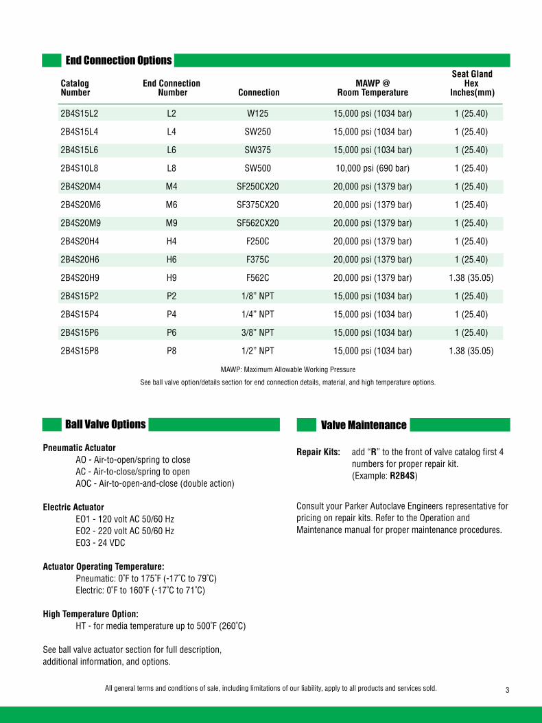
3All general terms and conditions of sale, including limitations of our liability, apply to all products and services sold.
End Connection Options
Catalog End Connection MAWP @ Hex Number Number Connection Room Temperature Inches(mm)
2B4S15L2 L2 W125 15,000 psi (1034 bar) 1 (25.40)
2B4S15L4 L4 SW250 15,000 psi (1034 bar) 1 (25.40)
2B4S15L6 L6 SW375 15,000 psi (1034 bar) 1 (25.40)
2B4S10L8 L8 SW500 10,000 psi (690 bar) 1 (25.40)
2B4S20M4 M4 SF250CX20 20,000 psi (1379 bar) 1 (25.40)
2B4S20M6 M6 SF375CX20 20,000 psi (1379 bar) 1 (25.40)
2B4S20M9 M9 SF562CX20 20,000 psi (1379 bar) 1 (25.40)
2B4S20H4 H4 F250C 20,000 psi (1379 bar) 1 (25.40)
2B4S20H6 H6 F375C 20,000 psi (1379 bar) 1 (25.40)
2B4S20H9 H9 F562C 20,000 psi (1379 bar) 1.38 (35.05)
2B4S15P2 P2 1/8” NPT 15,000 psi (1034 bar) 1 (25.40)
2B4S15P4 P4 1/4” NPT 15,000 psi (1034 bar) 1 (25.40)
2B4S15P6 P6 3/8” NPT 15,000 psi (1034 bar) 1 (25.40)
2B4S15P8 P8 1/2” NPT 15,000 psi (1034 bar) 1.38 (35.05)
Pneumatic Actuator AO - Air-to-open/spring to close AC - Air-to-close/spring to open AOC - Air-to-open-and-close (double action)
Electric Actuator EO1 - 120 volt AC 50/60 Hz EO2 - 220 volt AC 50/60 Hz EO3 - 24 VDC
Actuator Operating Temperature: Pneumatic: 0˚F to 175˚F (-17˚C to 79˚C) Electric: 0˚F to 160˚F (-17˚C to 71˚C)
High Temperature Option: HT - for media temperature up to 500˚F (260˚C)
See ball valve actuator section for full description, additional information, and options.
Repair Kits: add “R” to the front of valve catalog first 4 numbers for proper repair kit. (Example: R2B4S)
Consult your Parker Autoclave Engineers representative for pricing on repair kits. Refer to the Operation and Maintenance manual for proper maintenance procedures.
Valve Maintenance
MAWP: Maximum Allowable Working Pressure
See ball valve option/details section for end connection details, material, and high temperature options.
Ball Valve Options
Seat Gland
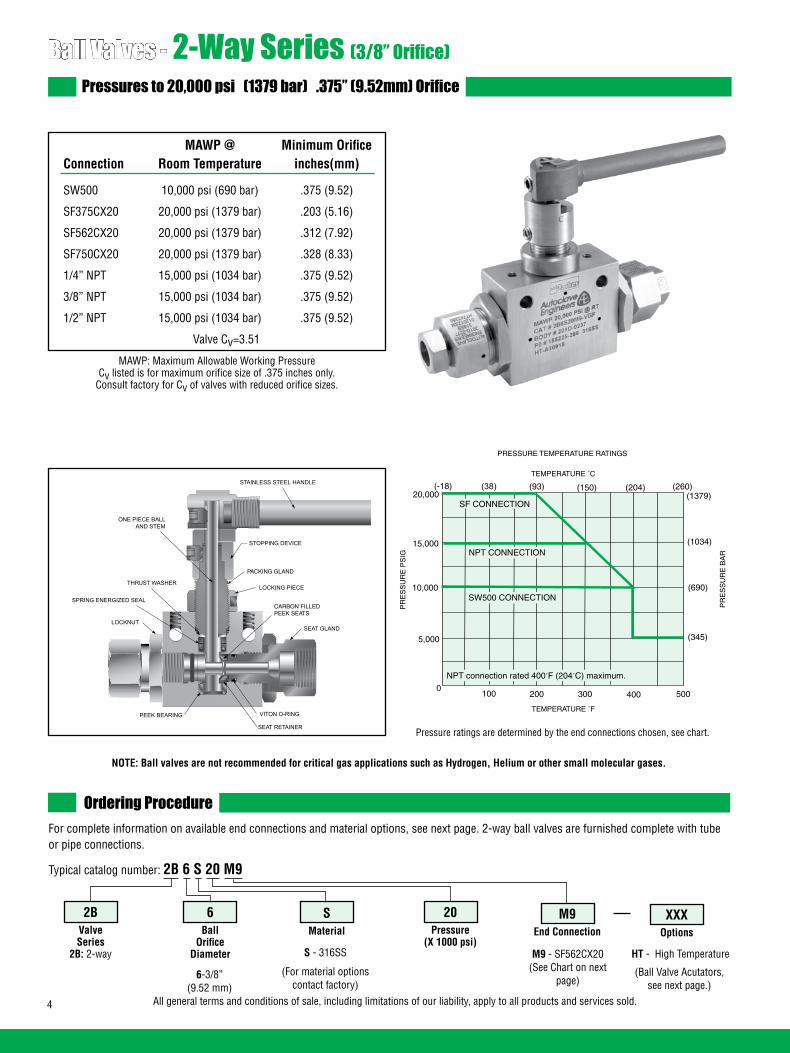
4 All general terms and conditions of sale, including limitations of our liability, apply to all products and services sold.
Ball Valves - 2-Way Series (3/8” Orifice)Pressures to 20,000 psi (1379 bar) .375” (9.52mm) Orifice
Ordering ProcedureFor complete information on available end connections and material options, see next page. 2-way ball valves are furnished complete with tube or pipe connections.
Typical catalog number: 2B 6 S 20 M9
6-3/8”(9.52 mm)
S - 316SS
(For material options contact factory)
M9 - SF562CX20 (See Chart on next
page)
M9End Connection
20Pressure
(X 1000 psi)
SMaterial
6Ball
OrificeDiameter
2BValveSeries
2B: 2-way
MAWP @ Minimum Orifice Connection Room Temperature inches(mm)
SW500 10,000 psi (690 bar) .375 (9.52)
SF375CX20 20,000 psi (1379 bar) .203 (5.16)
SF562CX20 20,000 psi (1379 bar) .312 (7.92)
SF750CX20 20,000 psi (1379 bar) .328 (8.33)
1/4” NPT 15,000 psi (1034 bar) .375 (9.52)
3/8” NPT 15,000 psi (1034 bar) .375 (9.52)
1/2” NPT 15,000 psi (1034 bar) .375 (9.52)
Valve Cv=3.51
HT - High Temperature
XXXOptions
(Ball Valve Acutators,see next page.)
MAWP: Maximum Allowable Working PressureCv listed is for maximum orifice size of .375 inches only.
Consult factory for Cv of valves with reduced orifice sizes.
NOTE: Ball valves are not recommended for critical gas applications such as Hydrogen, Helium or other small molecular gases.
TEMPERATURE ˚F
100 200 300 400 5000
5,000
10,000
15,000
20,000
PR
ES
SU
RE
PS
IG
PRESSURE TEMPERATURE RATINGS
SF CONNECTION
NPT CONNECTION
SW500 CONNECTION
*pressure ratings are determined by the end connections chosen, see chart.
(1379)
(1034)
(690)
(345)
TEMPERATURE ˚C
(-18) (38) (93) (150) (204) (260)
PR
ES
SU
RE
BA
R
NPT connection rated 400˚F (204˚C) maximum.
STAINLESS STEEL HANDLE
STOPPING DEVICE
PACKING GLAND
LOCKING PIECE
SEAT GLAND
VITON O-RING
SEAT RETAINER
PEEK BEARING
LOCKNUT
SPRING ENERGIZED SEAL
THRUST WASHER
ONE PIECE BALLAND STEM
CARBON FILLEDPEEK SEATS
Pressure ratings are determined by the end connections chosen, see chart.

5All general terms and conditions of sale, including limitations of our liability, apply to all products and services sold.
Ball Valve Options
Pneumatic Actuator AO - Air-to-open/spring to close AC - Air-to-close/spring to open AOC - Air-to-open-and-close (double action)
Electric Actuator EO1 - 120 volt AC 50/60 Hz EO2 - 220 volt AC 50/60 Hz EO3 - 24 VDC
Actuator Operating Temperature: Pneumatic: 0˚F to 175˚F (-17˚C to 79˚C) Electric: 0˚F to 160˚F (-17˚C to 71˚C)
High Temperature Option: HT - for media temperature up to 500˚F (260˚C)
See ball valve actuator section for full description, additional information, and options.
Repair Kits: add “R” to the front of valve catalog first 4 numbers for proper repair kit. (Example: R2B6S)
Consult your Parker Autoclave Engineers representative for pricing on repair kits. Refer to the Operation and Maintenance manual for proper maintenance procedures.
Valve Maintenance
End Connection Options
Catalog End Connection MAWP @ Hex Number Number Connection Room Temperature Inches(mm)
2B6S10L8 L8 SW500 10,000 psi (690 bar) 1.38 (35.05)
2B6S20M6 M6 SF375CX20 20,000 psi (1379 bar) 1.38 (35.05)
2B6S20M9 M9 SF562CX20 20,000 psi (1379 bar) 1.38 (35.05)
2B6S20M12 M12 SF750CX20 20,000 psi (1379 bar) 1.38 (35.05)
2B6S15P4 P4 1/4” NPT 15,000 psi (1034 bar) 1.38 (35.05)
2B6S15P6 P6 3/8” NPT 15,000 psi (1034 bar) 1.38 (35.05)
2B6S15P8 P8 1/2” NPT 15,000 psi (1034 bar) 1.38 (35.05)
MAWP: Maximum Allowable Working Pressure
See ball valve option/details section for end connection details, material, and high temperature options.
Seat Gland
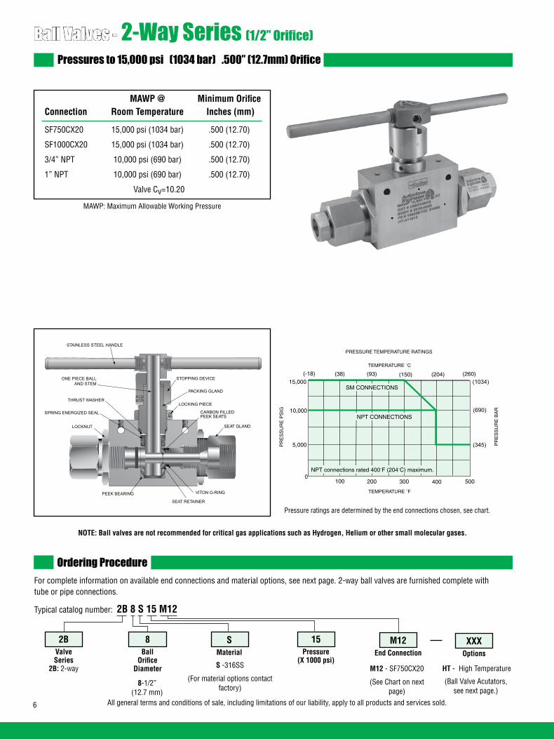
6 All general terms and conditions of sale, including limitations of our liability, apply to all products and services sold.
Ball Valves - 2-Way Series (1/2” Orifice)Pressures to 15,000 psi (1034 bar) .500” (12.7mm) Orifice
Ordering ProcedureFor complete information on available end connections and material options, see next page. 2-way ball valves are furnished complete with tube or pipe connections.
Typical catalog number: 2B 8 S 15 M12
8-1/2”(12.7 mm)
S -316SS
(For material options contact factory)
M12 - SF750CX20
(See Chart on next page)
M12End Connection
15Pressure
(X 1000 psi)
SMaterial
8Ball
OrificeDiameter
2BValveSeries
2B: 2-way
MAWP @ Minimum Orifice Connection Room Temperature Inches (mm)
SF750CX20 15,000 psi (1034 bar) .500 (12.70)
SF1000CX20 15,000 psi (1034 bar) .500 (12.70)
3/4” NPT 10,000 psi (690 bar) .500 (12.70)
1” NPT 10,000 psi (690 bar) .500 (12.70)
Valve Cv=10.20
HT - High Temperature
XXXOptions
(Ball Valve Acutators,see next page.)
MAWP: Maximum Allowable Working Pressure
NOTE: Ball valves are not recommended for critical gas applications such as Hydrogen, Helium or other small molecular gases.
STAINLESS STEEL HANDLE
STOPPING DEVICE
PACKING GLAND
LOCKING PIECE
SEAT GLAND
VITON O-RING
SEAT RETAINER
PEEK BEARING
LOCKNUT
SPRING ENERGIZED SEAL
THRUST WASHER
ONE PIECE BALLAND STEM
CARBON FILLEDPEEK SEATS
TEMPERATURE ˚F
100 200 300 400 5000
5,000
10,000
15,000
PR
ES
SU
RE
PS
IG
PRESSURE TEMPERATURE RATINGS
NPT CONNECTIONS
(1034)
(690)
(345)
TEMPERATURE ˚C
(-18) (38) (93) (150) (204) (260)
PR
ES
SU
RE
BA
R
SM CONNECTIONS
NPT connections rated 400˚F (204˚C) maximum.
Pressure ratings are determined by the end connections chosen, see chart.

7All general terms and conditions of sale, including limitations of our liability, apply to all products and services sold.
Ball Valve Options
Pneumatic Actuator AO - Air-to-open/spring to close AC - Air-to-close/spring to open AOC - Air-to-open-and-close (double action)
Electric Actuator EO1 - 120 volt AC 50/60 Hz EO2 - 220 volt AC 50/60 Hz EO3 - 24 VDC
Actuator Operating Temperature: Pneumatic: 0˚F to 175˚F (-17˚C to 79˚C) Electric: 0˚F to 160˚F (-17˚C to 71˚C)
High Temperature Option: HT - for media temperature up to 500˚F (260˚C)
See ball valve Actuator section for full description, additional information, and options.
Repair Kits: add “R” to the front of valve catalog first 4 numbers for proper repair kit. (Example: R2B8S)
Consult your Parker Autoclave Engineers representative for pricing on repair kits. Refer to the Operation and Maintenance manual for proper maintenance procedures.
Valve Maintenance
End Connection Options
Catalog End Connection MAWP @ Hex Number Number Connection Room Temperature Inches(mm)
2B8S15M12 M12 SF750CX20 15,000 psi (1034 bar) 1.75 (44.5)
2B8S15M16 M16 SF1000CX20 15,000 psi (1034 bar) 1.75 (44.5)
2B8S10P12 P12 3/4” NPT 10,000 psi (690 bar) 1.75 (44.5)
2B8S10P16 P16 1” NPT 10,000 psi (690 bar) 1.75 (44.5)
MAWP: Maximum Allowable Working Pressure
See ball valve option/details section for end connection details, material, and high temperature options.
Seat Gland

8 All general terms and conditions of sale, including limitations of our liability, apply to all products and services sold.
Ball Valve Dimensions - inches (mm)
Ball Valve Panel Mounting Dimensions - inches (mm)
VALVE MODELS
2B4S 2B6S 2B8S 4.33 4.97 5.97 (109.99) (126.30) (151.64)
4.19 5.53 7.73 (106.49) (140.41) (196.46)
2.00 3.00 4.13 (50.80) (76.20) (104.78)
3.37 4.99 5.12 (85.55) (126.82) (130.04)
3.90 5.52 10.25 (99.02) (140.32) (260.35)
1.13 1.38 1.76 (28.58) (34.92) (44.70)
1.50 2.00 3.00 (38.10) (50.80) (76.20)
0.75 1.00 1.50 (19.05) (25.40) (38.10)
0.43 0.41 0.50 (10.92) (10.31) (12.70)
0.28 0.28 0.28 (7.11) (7.11) (7.11)
1.91 2.50 3.09 (48.41) (63.50) (78.58)
1.00 1.38 1.75 (25.40) (34.92) (44.45)
VALVE MODELS
2B4S 2B6S 2B8S 1.500 2.000 3.000 (38.10) (50.80) (76.20)
0.750 1.000 1.500 (19.05) (25.40) (38.10)
1.06 1.50 1.88 (26.92) (38.10) (47.63)
0.28 0.28 0.28 (7.11) (7.11) (7.11)
Note: Body mounting 1/4” - 20 thread
A
B
C
D
E
F
G
H
J
K
L
BlockThickness
A
B
C
D
*
C (Diameter)
D (Typical Diameter)
A
B
All dimensions are for reference only and are subject to change without notice.
See Note:
L
K TYPICAL DIAMETER
BLOCK THICKNESS
B
D
C
F
A
JTYPICAL
H
G
E
E*
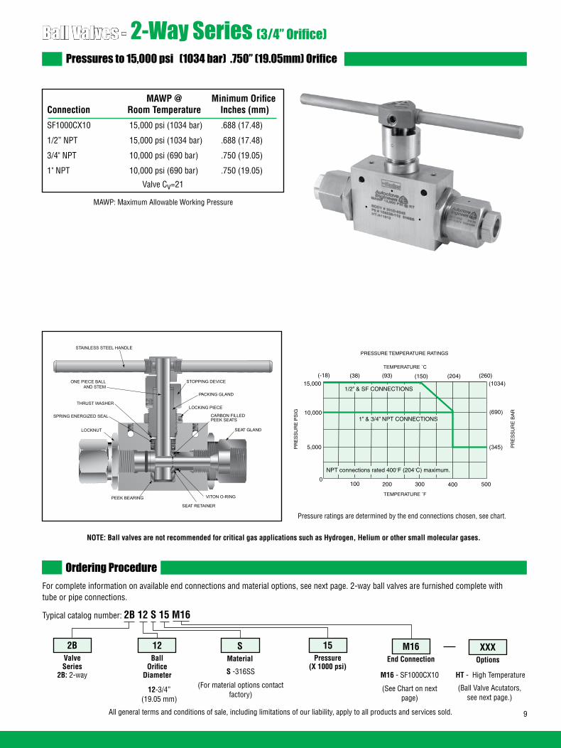
9All general terms and conditions of sale, including limitations of our liability, apply to all products and services sold.
Ball Valves - 2-Way Series (3/4” Orifice)Pressures to 15,000 psi (1034 bar) .750” (19.05mm) Orifice
Ordering ProcedureFor complete information on available end connections and material options, see next page. 2-way ball valves are furnished complete with tube or pipe connections.
Typical catalog number: 2B 12 S 15 M16
12-3/4”(19.05 mm)
S -316SS
(For material options contact factory)
M16 - SF1000CX10
(See Chart on next page)
M16End Connection
15Pressure
(X 1000 psi)
SMaterial
12Ball
OrificeDiameter
2BValveSeries
2B: 2-way HT - High Temperature
XXXOptions
(Ball Valve Acutators,see next page.)
MAWP: Maximum Allowable Working Pressure
NOTE: Ball valves are not recommended for critical gas applications such as Hydrogen, Helium or other small molecular gases.
STAINLESS STEEL HANDLE
STOPPING DEVICE
PACKING GLAND
LOCKING PIECE
SEAT GLAND
VITON O-RING
SEAT RETAINER
PEEK BEARING
LOCKNUT
SPRING ENERGIZED SEAL
THRUST WASHER
ONE PIECE BALLAND STEM
CARBON FILLEDPEEK SEATS
MAWP @ Minimum Orifice Connection Room Temperature Inches (mm)
SF1000CX10 15,000 psi (1034 bar) .688 (17.48)
1/2” NPT 15,000 psi (1034 bar) .688 (17.48)
3/4" NPT 10,000 psi (690 bar) .750 (19.05)
1" NPT 10,000 psi (690 bar) .750 (19.05)
TEMPERATURE ˚F
100 200 300 400 5000
5,000
10,000
15,000
PR
ES
SU
RE
PS
IG
PRESSURE TEMPERATURE RATINGS
1” & 3/4” NPT CONNECTIONS
(1034)
(690)
(345)
TEMPERATURE ˚C
(-18) (38) (93) (150) (204) (260)
PR
ES
SU
RE
BA
R
1/2” & SF CONNECTIONS
NPT connections rated 400˚F (204˚C) maximum.
Valve Cv=21
Pressure ratings are determined by the end connections chosen, see chart.

10 All general terms and conditions of sale, including limitations of our liability, apply to all products and services sold.
Ball Valve Options
Valve Actuators Consult Factory
Actuator Operating Temperature: Pneumatic: 0˚F to 175˚F (-17˚C to 79˚C) Electric: 0˚F to 160˚F (-17˚C to 71˚C)
Repair Kits: add “R” to the front of valve catalog first 4 numbers for proper repair kit. (Example: R2B12S)
Consult your Parker Autoclave Engineers representative for pricing on repair kits. Refer to the Operation and Maintenance manual for proper maintenance procedures.
Valve Maintenance
End Connection Options
Catalog End Connection MAWP @ Hex Number Number Connection Room Temperature Inches(mm)
2B12S15M16 M16 SF1000CX10 15,000 psi (1034 bar) 1.88 (47.6)
2B12S15P8 P8 1/2" NPT 15,000 psi (1034 bar) 1.88 (47.6)
2B12S10P12 P12 3/4" NPT 10,000 psi (690 bar) 1.88 (47.6)
2B12S10P16 P16 1" NPT 10,000 psi (690 bar) 1.88 (47.6)
MAWP: Maximum Allowable Working Pressure
See ball valve option/details section for end connection details, material, and high temperature options.
Seat Gland

11All general terms and conditions of sale, including limitations of our liability, apply to all products and services sold.
Ball Valve Dimensions - inches (mm)
Ball Valve Panel Mounting Dimensions - inches (mm)
All dimensions are for reference only and are subject to change without notice.
NOTE: Body mounting 3/8”-16 thread
2.38 (60.3)
.44 (11.2)(Typical Diameter)See Note:
1.63(41.4)
3.25(82.6)
22.00(558.8)
11.00 (279.4)
10.13(257.3)
3.25(82.6)
1.63(41.4)
0.69 (17.5)TYPICAL
.41 (10.4)TYPICAL DIAMETER
3.00 (76.2)BLOCK THICKNESS
4.50(114.3)
9.18(233.2)
2.47(62.7)
4.50(114.3)

12 All general terms and conditions of sale, including limitations of our liability, apply to all products and services sold.
Ball Valves - 2-Way Series (1” Orifice)Pressures to 10,000 psi (690 bar) 1.000” (25.40mm) Orifice
Ordering ProcedureFor complete information on available end connections and material options, see next page. 2-way ball valves are furnished complete with tube or pipe connections.
Typical catalog number: 2B 16 S 10 MA24
16-1.0”(25.40 mm)
S -316SS
(For material options contact factory)
MA24 - SM1500CX10
(See Chart on next page)
MA24End Connection
10Pressure
(X 1000 psi)
SMaterial
16Ball
OrificeDiameter
2BValveSeries
2B: 2-way HT - High Temperature
XXXOptions
(Ball Valve Acutators,see next page.)
MAWP: Maximum Allowable Working Pressure
NOTE: Ball valves are not recommended for critical gas applications such as Hydrogen, Helium or other small molecular gases.
STAINLESS STEEL HANDLE
STOPPING DEVICE
PACKING GLAND
LOCKING PIECE
SEAT GLAND
VITON O-RING
SEAT RETAINER
PEEK BEARING
LOCKNUT
SPRING ENERGIZED SEAL
THRUST WASHER
ONE PIECE BALLAND STEM
CARBON FILLEDPEEK SEATS
MAWP @ Minimum Orifice Connection Room Temperature Inches (mm) Valve Cv
SM1500CX10 (Male) 10,000 psi (690 bar) .938 (23.83) 30
1” SAE (Female) 10,000 psi (690 bar) 1.00 (25.40) 34
1” NPT (Female) 10,000 psi (690 bar) 1.00 (25.40) 34
TEMPERATURE ˚F
100 200 300 400 5000
5,000
10,000
15,000
PR
ES
SU
RE
PS
IG
PRESSURE TEMPERATURE RATINGS
(1034)
(690)
(345)
TEMPERATURE �C
(-18) (38) (93) (150) (204) (260)
PR
ES
SU
RE
BA
R
NPT, SAE & SM CONNECTIONS
NPT connections rated 400˚F (204˚C) maximum.
Pressure ratings are determined by the end connections chosen, see chart.

13All general terms and conditions of sale, including limitations of our liability, apply to all products and services sold.
Ball Valve Options
Valve Actuators Consult Factory
Actuator Operating Temperature: Pneumatic: 0˚F to 175˚F (-17˚C to 79˚C) Electric: 0˚F to 160˚F (-17˚C to 71˚C)
Repair Kits: add “R” to the front of valve catalog first 4 numbers for proper repair kit. (Example: R2B16S)
Consult your Parker Autoclave Engineers representative for pricing on repair kits. Refer to the Operation and Maintenance manual for proper maintenance procedures.
Valve Maintenance
End Connection Options
Catalog End Connection MAWP @ Hex Number Number Connection Room Temperature Inches(mm)
2B16S10MA24 M24 SM1500CX10 (Male) 10,000 psi (690 bar) 1.88 (47.6)
2B16S10S16 S16 1" SAE (Female) 10,000 psi (690 bar) 1.88 (47.6)
2B16S10P16 P16 1" NPT (Female) 10,000 psi (690 bar) 1.88 (47.6)
MAWP: Maximum Allowable Working Pressure
See ball valve option/details section for end connection details, material, and high temperature options.
Seat Gland
*Square

14 All general terms and conditions of sale, including limitations of our liability, apply to all products and services sold.
Ball Valve Dimensions - inches (mm)
Ball Valve Panel Mounting Dimensions - inches (mm)
L
28.00(711.2)
14.00 (355.6)
11.87(301.5)
4.00(101.6)
2.00(50.8)
0.88 (22.2)TYPICAL
.53 (13.5)TYPICAL DIAMETER
3.38 (85.9)BLOCK THICKNESS
5.00(127.00)
8.41(213.7)
20.74(526.7)
3.10(78.6)
5.46(138.6)
*SM1500CX20 Connection Only
Female Connection Only
All dimensions are for reference only and are subject to change without notice.
NOTE: Body mounting 3/8”-16 thread
2.94 (74.7)
.44 (11.2)(Typical Diameter)See Note:
2.000(50.8)
4.000(101.6)
1.500(38.1)
.750 (19.1)

15All general terms and conditions of sale, including limitations of our liability, apply to all products and services sold.

16 All general terms and conditions of sale, including limitations of our liability, apply to all products and services sold.
02-0105SE January2013© 2013 Parker Hannifin Corporation | Autoclave Engineers is a registered trademark of the Parker Hannifin Corporation
Parker Hannifin Manufacturing Ltd. Instrumentation Products Division, Europe Industrial Estate WhitemillWexford, Republic of IrelandPH: 353 53 914 1566FAX: 353 53 914 1582
Instrumentation Products DivisionAutoclave Engineers Operation8325 Hessinger DriveErie, Pennsylvania 16509-4679 USAPH: 814-860-5700 FAX: 814-860-5811www.autoclave.com
WARNINGFAILURE, IMPROPER SELECTION OR IMPROPER USE OF THE PRODUCTS AND/OR SYSTEMS DESCRIBED HEREIN OR RELATED ITEMS CAN CAUSE DEATH, PERSONAL INJURY AND PROPERTY DAMAGE.This document and other information from Parker Hannifin Corporation, its subsidiaries and authorized distributors provide product and/or system options for further investiga-tion by users having technical expertise. It is important that you analyze all aspects of your application and review the information concerning the product or system in the current product catalog. Due to the variety of operating conditions and applications for these products or systems, the user, through its own analysis and testing, is solely responsible for making the final selection of the products and systems and assuring that all performance, safety and warning requirements of the application are met. The products described herein, including without limitation, product features, specifications, designs, availability and pricing, are subject to change by Parker Hannifin Corporation and its subsidiaries at any time without notice.
Offer of SaleThe items described in this document are available for sale by Parker Hannifin Corporation, its subsidiaries or its authorized distributors. Any sale contract entered by Parker will begoverned by the provisions stated in Parker's standard terms and conditions of sale (copy available upon request).
ISO-9001 Certified
Caution! Do not mix or interchange parts or tubing with those of other manufacturers. Doing so is unsafe and will void warranty.
Caution! Parker Autoclave Engineers Valves, Fittings and Tools are not designed to work with common commercial instrument tubing and will only work with tubing built to Parker Autoclave Engineers AES Specifications. Failure to do so will void warranty.

1All general terms and conditions of sale, including limitations of our liability, apply to all products and services sold.
Ball Valves3-Way SeriesPressures to 20,000 psi (1379 bar)
Ball Valves - 3-Way Series
Flow Configuration
Applications:
• Laboratories• Test Stands• Control Panels• Chemical Research• Pilot Plants• Water Blast Pumping Units• High volume chemical injection
skids.
3-WayDiverting
90 Turn
3-WayCrossover90° Turn
3-WaySwitching180° Turn
3-WaySwitching
180 Turn
www.autoclave.com
Ball Valve Features:• One-piece, trunnion mounted style, stem design
eliminates shear failure found in two piece designs and reduces effects of side loading.
• Re-torqueable seat glands for longer seat life.
• Carbon filled PEEK seats offer excellent resistance to chemicals, heat, and wear/abrasion.
• Full-port flow path minimizes pressure drop.
• 316 cold worked stainless steel construction.
• Low friction pressure assisted graphite filled PTFE stem seal increases cycle life and reduces operating torque.
• Available in 90° turn diverter and 180° turn switching models.
• Viton o-rings for operation from 0°F (-17.8°C) to 400°F (204°C).
• Optional o-rings available for high-temperature applications.
• Optional wetted materials.
• Wide selection of tube and pipe end fittings available.
• Electric and pneumatic actuator options.
Parker Autoclave Engineers high-pressure ball valves have been designed to provide superior quality for maximum performance within a variety of valve styles, sizes, and process connections. Some of the more unique design innovations include an integral one-piece trunnion mounted style ball and stem that eliminates the shear failure common in two piece designs, re-torqueable seat glands that result in longer seat life, and a low friction stem seal that reduces actuation torque and enhances cycle life.
These ball valves can also be modified to incorporate the use of special materials, seals for high temperature applications, subsea models, and valve actuators.
When it comes to high-pressure applications, these ball valves with the associated high-pressure components, provide the critical performance demanded by the high pressure market.

2 All general terms and conditions of sale, including limitations of our liability, apply to all products and services sold.
Ball Valves - 3/16" 3-Way SeriesPressures to 20,000 psi (1379 bar) .187” (4.77mm) Orifice
Ordering ProcedureFor complete information on available end connections and material options, see next page. 3-way ball valves are furnished complete with tube or pipe connections.
Typical catalog number: 3B 3 S 20 M9
3-3/16”(4.77 mm)
S -316SS
(For material options contact factory)
M9 - SF562CX20 (See Chart on next page)
M9End Connection
20Pressure
(X 1000 psi)
SMaterial
3Ball
OrificeDiameter
3BValveSeries
3B: 3-way 3BD: 3-way diverter
MAWP @ Minimum Orifice Connection Room Temperature inches(mm)
W125 15,000 psi (1034 bar) .094 (2.39)
SW250 15,000 psi (1034 bar) .128 (3.25)
SW375 15,000 psi (1034 bar) .188 (4.77)
SW500 10,000 psi (690 bar) .188 (4.77)
SF250CX20 20,000 psi (1379 bar) .109 (2.77)
SF375CX20 20,000 psi (1379 bar) .188 (4.77)
SF562CX20 20,000 psi (1379 bar) .188 (4.77)
F250C 20,000 psi (1379 bar) .094 (2.39)
F375C 20,000 psi (1379 bar) .125 (3.17)
F562C 20,000 psi (1379 bar) .188 (4.77)
1/8” NPT 15,000 psi (1034 bar) .188 (4.77)
1/4” NPT 15,000 psi (1034 bar) .188 (4.77)
3/8” NPT 15,000 psi (1034 bar) .188 (4.77)
1/2” NPT 15,000 psi (1034 bar) .188 (4.77)
HT - High Temperature
XXXOptions
(Ball Valve Actuators, see next page)
MAWP: Maximum Allowable Working PressureCv listed is for maximum orifice size of .188 inches only.
Consult factory for Cv of valves with reduced orifice sizes.
NOTE: Ball valves are not recommended for critical gas applications such as Hydrogen, Helium or other small molecular gases.
Valve Cv=.50
LOCKNUT
STAINLESS STEEL HANDLE
STOPPING DEVICE
PACKING GLAND
LOCKING PIECE
O-RING
O-RING
SEAT RETAINER
BOTTOM GLAND
SPRING ENERGIZED SEAL
THRUST WASHER
SET SCREW
BELLEVILLE BACKUP
BEARING
O-RINGCARBON FILLED PEEK SEATS
BELLEVILLE WASHERS
ONE PIECE BALLAND STEM
SEAT GLAND
TEMPERATURE ˚F
100 200 300 400 5000
5,000
10,000
15,000
20,000
PR
ES
SU
RE
PS
IG
PRESSURE TEMPERATURE RATINGS
PR
ES
SU
RE
BA
R
(345)
(690)
(1034)
(1379)(-18) (38) (93) (150) (204) (260)
TEMPERATURE ˚C
SF & F CONNECTIONS See Note
W125, SW250, SW375, & NPT CONNECTIONS
SW500 CONNECTION
NPT connections rated 400˚F (204˚C) maximum.
Pressure ratings are determined by the end connections chosen, see chart.Note: Maximum side connection inlet pressure 15,000 psi (1034 bar)

3All general terms and conditions of sale, including limitations of our liability, apply to all products and services sold.
End Connection Options Catalog End Connection MAWP @ Hex Number Number Connection Room Temperature Inches(mm)
3B3S15L2 L2 W125 15,000 psi (1034 bar) 1 (25.40) 3BD3S15L2 3B3S15L4 L4 SW250 15,000 psi (1034 bar) 1 (25.40) 3BD3S15L4 3B3S15L6 L6 SW375 15,000 psi (1034 bar) 1 (25.40) 3BD3S15L6 3B3S10L8 L8 SW500 10,000 psi (690 bar) 1 (25.40) 3BD3S10L8 3B3S20M4 M4 SF250CX20 20,000 psi (1379 bar) 1 (25.40) 3BD3S20M4 3B3S20M6 M6 SF375CX20 20,000 psi (1379 bar) 1 (25.40) 3BD3S20M6 3B3S20M9 M9 SF562CX20 20,000 psi (1379 bar) 1 (25.40) 3BD3S20M9 3B3S20H4 H4 F250C 20,000 psi (1379 bar) 1 (25.40) 3BD3S20H4 3B3S20H6 H6 F375C 20,000 psi (1379 bar) 1 (25.40) 3BD3S20H6 3B3S20H9 H9 F562C 20,000 psi (1379 bar) 1.38 (35.05) 3BD3S20H9 3B3S15P2 P2 1/8” NPT 15,000 psi (1034 bar) 1 (25.40) 3BD3S15P2 3B3S15P4 P4 1/4” NPT 15,000 psi (1034 bar) 1 (25.40) 3BD3S15P4 3B3S15P6 P6 3/8” NPT 15,000 psi (1034 bar) 1 (25.40) 3BD3S15P6 3B3S15P8 P8 1/2” NPT 15,000 psi (1034 bar) 1.38 (35.05) 3BD3S15P8
Ball Valve OptionsPneumatic Actuator: AO - Air-to-open/Spring to close (diverter style only) AC - Air-to-close/Spring to open (diverter style only) AOC - Air-to-open-and-close (double action)Electric Actuator: EO1 - 120 volt AC 50/60 Hz EO2 - 220 volt AC 50/60 Hz EO3 - 24 VDCActuator Operating Temperature: Pneumatic: 0˚F to 175˚F (-17˚C to 79˚C) Electric: 0˚F to 160˚F (-17˚C to 71˚C)High Temperature Option: HT - for media temperature up to 500˚F (260˚C)
See ball valve option/detail section for end connection details, material, and high temperature options.
Repair Kits: add “R” to the front of valve catalog numbers for proper repair kit. (Example: R3B3S)
Consult your Parker Autoclave Engineers representative for pricing on repair kits. Refer to the Operation and Maintenance manual for proper maintenance procedures.
Valve Maintenance
*The Diverter Valve design permits inlet flow through the bottom port. Outlet flow may be diverted to either valve side port.
OPEN OPEN
*3-Way Diverter Valve 90° Turn
OPEN CLOSED
3-Way Ball Valve180 Turn
OPEN
See ball valve actuator section for full description, additional information, and options.
*3-Way Diverter Valve90° Turn
3-Way Ball Valve180° Turn
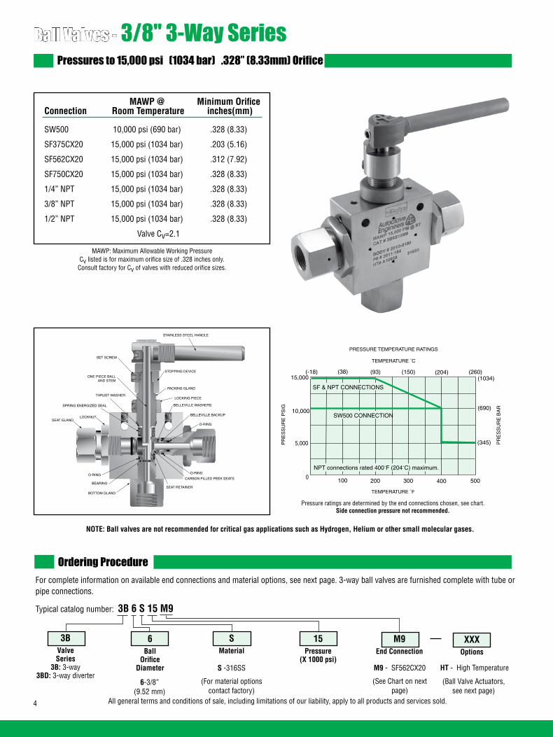
4 All general terms and conditions of sale, including limitations of our liability, apply to all products and services sold.
Ball Valves - 3/8" 3-Way SeriesPressures to 15,000 psi (1034 bar) .328” (8.33mm) Orifice
Ordering ProcedureFor complete information on available end connections and material options, see next page. 3-way ball valves are furnished complete with tube or pipe connections.
Typical catalog number: 3B 6 S 15 M9
6-3/8”(9.52 mm)
S -316SS
(For material options contact factory)
M9 - SF562CX20
(See Chart on next page)
M9End Connection
15Pressure
(X 1000 psi)
SMaterial
6Ball
OrificeDiameter
3BValveSeries
3B: 3-way 3BD: 3-way diverter
HT - High Temperature
XXXOptions
(Ball Valve Actuators, see next page)
MAWP: Maximum Allowable Working PressureCv listed is for maximum orifice size of .328 inches only.
Consult factory for Cv of valves with reduced orifice sizes.
NOTE: Ball valves are not recommended for critical gas applications such as Hydrogen, Helium or other small molecular gases.
LOCKNUT
STAINLESS STEEL HANDLE
STOPPING DEVICE
PACKING GLAND
LOCKING PIECE
O-RING
O-RING
SEAT RETAINER
BOTTOM GLAND
SPRING ENERGIZED SEAL
THRUST WASHER
SET SCREW
BELLEVILLE BACKUP
BEARING
O-RINGCARBON FILLED PEEK SEATS
BELLEVILLE WASHERS
ONE PIECE BALLAND STEM
SEAT GLAND
MAWP @ Minimum Orifice Connection Room Temperature inches(mm)
SW500 10,000 psi (690 bar) .328 (8.33)
SF375CX20 15,000 psi (1034 bar) .203 (5.16)
SF562CX20 15,000 psi (1034 bar) .312 (7.92)
SF750CX20 15,000 psi (1034 bar) .328 (8.33)
1/4” NPT 15,000 psi (1034 bar) .328 (8.33)
3/8” NPT 15,000 psi (1034 bar) .328 (8.33)
1/2” NPT 15,000 psi (1034 bar) .328 (8.33)
Valve Cv=2.1
TEMPERATURE ˚F
100 200 300 400 5000
5,000
10,000
15,000
PR
ES
SU
RE
PS
IG
PRESSURE TEMPERATURE RATINGS
Pressure ratings are determined by the end connections chosen, see chart.Side connection pressure not recommended.
(345)
(690)
(1034)(-18) (38) (93) (150) (204) (260)
TEMPERATURE ˚C
PR
ES
SU
RE
BA
R
SF & NPT CONNECTIONS
SW500 CONNECTION
NPT connections rated 400˚F (204˚C) maximum.

5All general terms and conditions of sale, including limitations of our liability, apply to all products and services sold.
End Connection Options
Catalog End Connection MAWP @ Hex Number Number Connection Room Temperature Inches(mm)
3B6S10L8 L8 SW500 10,000 psi (690 bar) 1.38 (35.05) 3BD6S10L8 3B6S15M6 M6 SF375CX20 15,000 psi (1034 bar) 1.38 (35.05) 3BD6S15M6 3B6S15M9 M9 SF562CX20 15,000 psi (1034 bar) 1.38 (35.05) 3BD6S15M9 3B6S15M12 M12 SF750CX20 15,000 psi (1034 bar) 1.38 (35.05) 3BD6S15M12 3B6S15P4 P4 1/4” NPT 15,000 psi (1034 bar) 1.38 (35.05) 3BD6S15P4 3B6S15P6 P6 3/8” NPT 15,000 psi (1034 bar) 1.38 (35.05) 3BD6S15P6 3B6S15P8 P8 1/2” NPT 15,000 psi (1034 bar) 1.38 (35.05) 3BD6S15P8
Ball Valve Options
Pneumatic Actuator: AO - Air-to-open/Spring to close (diverter style only) AC - Air-to-close/Spring to open (diverter style only) AOC - Air-to-open-and-close (double action)Electric Actuator: EO1 - 120 volt AC 50/60 Hz EO2 - 220 volt AC 50/60 Hz EO3 - 24 VDCActuator Operating Temperature: Pneumatic: 0˚F to 175˚F (-17˚C to 79˚C) Electric: 0˚F to 160˚F (-17˚C to 71˚C)High Temperature Option: HT - for media temperature up to 500˚F (260˚C)
See ball valve option/details section for end connection details, material, and high temperature options.
Repair Kits: add “R” to the front of valve catalog numbers for proper repair kit. (Example: R3B6S)
Consult your Parker Autoclave Engineers representative for pricing on repair kits. Refer to the Operation and Maintenance manual for proper maintenance procedures.
See ball valve actuator section for full description, additional information, and options.
Valve Maintenance
*The Diverter Valve design permits inlet flow through the bottom port. Outlet flow may be diverted to either valve side port.
OPEN CLOSED
3-Way Ball Valve180 Turn
OPENOPEN OPEN
*3-Way Diverter Valve 90° Turn
MAWP: Maximum Allowable Working Pressure
*3-Way Diverter Valve90° Turn
3-Way Ball Valve180° Turn
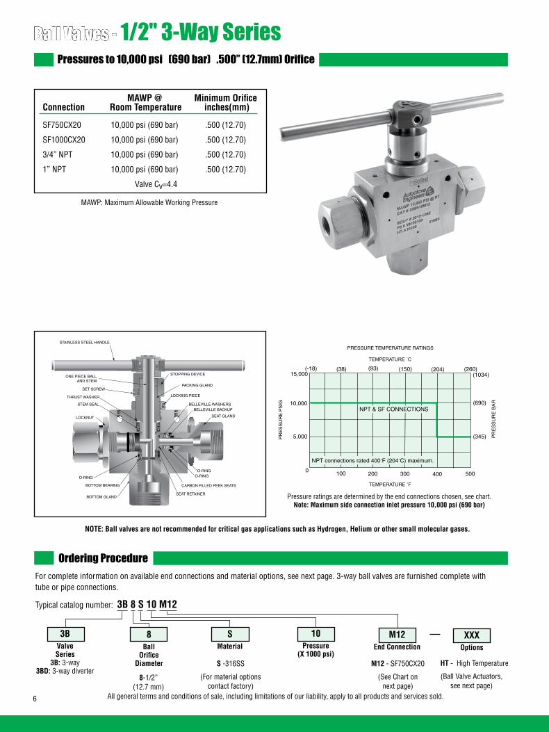
6 All general terms and conditions of sale, including limitations of our liability, apply to all products and services sold.
Ball Valves - 1/2" 3-Way SeriesPressures to 10,000 psi (690 bar) .500” (12.7mm) Orifice
MAWP @ Minimum Orifice Connection Room Temperature inches(mm)
SF750CX20 10,000 psi (690 bar) .500 (12.70)
SF1000CX20 10,000 psi (690 bar) .500 (12.70)
3/4” NPT 10,000 psi (690 bar) .500 (12.70)
1” NPT 10,000 psi (690 bar) .500 (12.70)
Valve Cv=4.4
Ordering ProcedureFor complete information on available end connections and material options, see next page. 3-way ball valves are furnished complete with tube or pipe connections.
Typical catalog number: 3B 8 S 10 M12
8-1/2”(12.7 mm)
S -316SS
(For material options contact factory)
M12 - SF750CX20
(See Chart on next page)
M12End Connection
10Pressure
(X 1000 psi)
SMaterial
8Ball
OrificeDiameter
3BValveSeries
3B: 3-way 3BD: 3-way diverter
HT - High Temperature
XXXOptions
(Ball Valve Actuators, see next page)
MAWP: Maximum Allowable Working Pressure
NOTE: Ball valves are not recommended for critical gas applications such as Hydrogen, Helium or other small molecular gases.
TEMPERATURE ˚F
100 200 300 400 5000
5,000
10,000
15,000
PR
ES
SU
RE
PS
IG
PRESSURE TEMPERATURE RATINGS
NPT & SF CONNECTIONS
(345)
(690)
(1034)(260)
TEMPERATURE �C
PR
ES
SU
RE
BA
R
(-18) (38) (93) (150) (204)
NPT connections rated 400˚F (204˚C) maximum.
ONE PIECE BALLAND STEM
O-RING
STAINLESS STEEL HANDLE
STOPPING DEVICE
PACKING GLAND
LOCKING PIECE
SEAT GLAND
O-RING
CARBON FILLED PEEK SEATS BOTTOM BEARING
LOCKNUT
STEM SEAL
THRUST WASHER
BELLEVILLE WASHERS
SEAT RETAINER BOTTOM GLAND
O-RING
BELLEVILLE BACKUP
SET SCREW
Pressure ratings are determined by the end connections chosen, see chart.Note: Maximum side connection inlet pressure 10,000 psi (690 bar)

7All general terms and conditions of sale, including limitations of our liability, apply to all products and services sold.
End Connection Options
Catalog End Connection MAWP @ Hex Number Number Connection Room Temperature Inches(mm)
3B8S10M12 M12 SF750CX20 10,000 psi (690 bar) 1.75 (44.5) 3BD8S10M12 3B8S10M16 M16 SF1000CX20 10,000 psi (690 bar) 1.75 (44.5) 3BD8S10M16 3B8S10P12 P12 3/4” NPT 10,000 psi (690 bar) 1.75 (44.5) 3BD8S10P12 3B8S10P16 P16 1” NPT 10,000 psi (690 bar) 1.75 (44.5) 3BD8S10P16
Ball Valve Options
Pneumatic Actuator: AO - Air-to-open/Spring to close (diverter style only) AC-Air-to-open/Spring to close (diverter style only) AOC - Air-to-open-and-close (double action)Electric Actuator: EO1 - 120 volt AC 50/60 Hz EO2 - 220 volt AC 50/60 Hz E03 - 24 VDCActuator Operating Temperature: Pneumatic: 0˚F to 175˚F (-17˚C to 79˚C) Electric: 0˚F to 160˚F (-17˚C to 71˚C) High Temperature Option: HT - for media temperature up to 500˚F (260˚C)
See ball valve options for end connection details, material, and high temperature options.
Repair Kits: add “R” to the front of valve catalog numbers for proper repair kit. (Example: R3B8S)
Consult your Parker Autoclave Engineers representative for pricing on repair kits. Refer to the Operation and Maintenance manual for proper maintenance procedures.
See ball valve actuator section for full description, additional information, and options.
Valve Maintenance
*The Diverter Valve design permits inlet flow through the bottom port. Outlet flow may be diverted to either valve side port.
OPEN OPEN
*3-Way Diverter Valve 90° Turn
OPEN CLOSED
3-Way Ball Valve180 Turn
OPEN
MAWP: Maximum Allowable Working Pressure
*3-Way Diverter Valve90° Turn
3-Way Ball Valve180° Turn
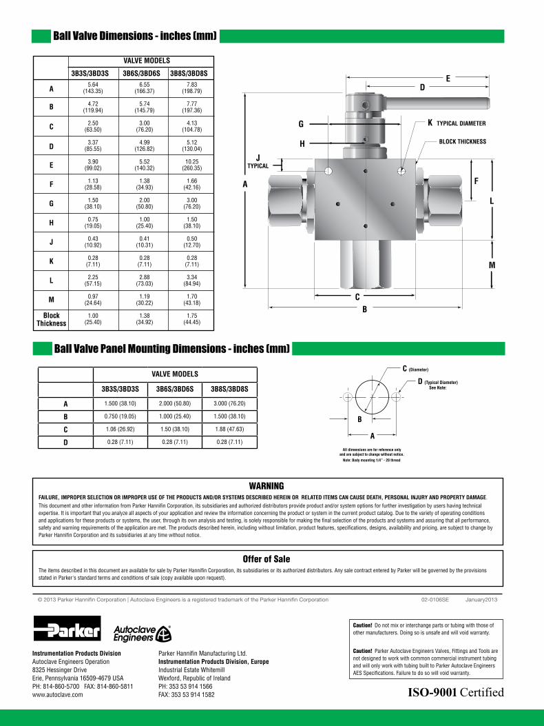
8 All general terms and conditions of sale, including limitations of our liability, apply to all products and services sold.
Ball Valve Dimensions - inches (mm)
Ball Valve Panel Mounting Dimensions - inches (mm)
BC
A
JTYPICAL
G
ED
L
F
K TYPICAL DIAMETER
BLOCK THICKNESSH
M
C (Diameter)
D (Typical Diameter)
A
B
All dimensions are for reference only and are subject to change without notice.
See Note:
Note: Body mounting 1/4” - 20 thread
VALVE MODELS
3B3S/3BD3S 3B6S/3BD6S 3B8S/3BD8S
A
B
C
D
E
F
G
H
J
K
L
M
BlockThickness
5.64 6.55 7.83 (143.35) (166.37) (198.79)
4.72 5.74 7.77 (119.94) (145.79) (197.36)
2.50 3.00 4.13 (63.50) (76.20) (104.78)
3.37 4.99 5.12 (85.55) (126.82) (130.04)
3.90 5.52 10.25 (99.02) (140.32) (260.35)
1.13 1.38 1.66 (28.58) (34.93) (42.16)
1.50 2.00 3.00 (38.10) (50.80) (76.20)
0.75 1.00 1.50 (19.05) (25.40) (38.10)
0.43 0.41 0.50 (10.92) (10.31) (12.70)
0.28 0.28 0.28 (7.11) (7.11) (7.11) 2.25 2.88 3.34 (57.15) (73.03) (84.94)
0.97 1.19 1.70 (24.64) (30.22) (43.18)
1.00 1.38 1.75 (25.40) (34.92) (44.45)
02-0106SE January2013© 2013 Parker Hannifin Corporation | Autoclave Engineers is a registered trademark of the Parker Hannifin Corporation
Parker Hannifin Manufacturing Ltd. Instrumentation Products Division, Europe Industrial Estate WhitemillWexford, Republic of IrelandPH: 353 53 914 1566FAX: 353 53 914 1582
Instrumentation Products DivisionAutoclave Engineers Operation8325 Hessinger DriveErie, Pennsylvania 16509-4679 USAPH: 814-860-5700 FAX: 814-860-5811www.autoclave.com
WARNINGFAILURE, IMPROPER SELECTION OR IMPROPER USE OF THE PRODUCTS AND/OR SYSTEMS DESCRIBED HEREIN OR RELATED ITEMS CAN CAUSE DEATH, PERSONAL INJURY AND PROPERTY DAMAGE.This document and other information from Parker Hannifin Corporation, its subsidiaries and authorized distributors provide product and/or system options for further investigation by users having technical expertise. It is important that you analyze all aspects of your application and review the information concerning the product or system in the current product catalog. Due to the variety of operating conditions and applications for these products or systems, the user, through its own analysis and testing, is solely responsible for making the final selection of the products and systems and assuring that all performance, safety and warning requirements of the application are met. The products described herein, including without limitation, product features, specifications, designs, availability and pricing, are subject to change by Parker Hannifin Corporation and its subsidiaries at any time without notice.
Offer of SaleThe items described in this document are available for sale by Parker Hannifin Corporation, its subsidiaries or its authorized distributors. Any sale contract entered by Parker will be governed by the provisions stated in Parker's standard terms and conditions of sale (copy available upon request).
VALVE MODELS
3B3S/3BD3S 3B6S/3BD6S 3B8S/3BD8S
A 1.500 (38.10) 2.000 (50.80) 3.000 (76.20)
B 0.750 (19.05) 1.000 (25.40) 1.500 (38.10)
C 1.06 (26.92) 1.50 (38.10) 1.88 (47.63)
D 0.28 (7.11) 0.28 (7.11) 0.28 (7.11)
ISO-9001 Certified
Caution! Do not mix or interchange parts or tubing with those of other manufacturers. Doing so is unsafe and will void warranty.
Caution! Parker Autoclave Engineers Valves, Fittings and Tools are not designed to work with common commercial instrument tubing and will only work with tubing built to Parker Autoclave Engineers AES Specifications. Failure to do so will void warranty.
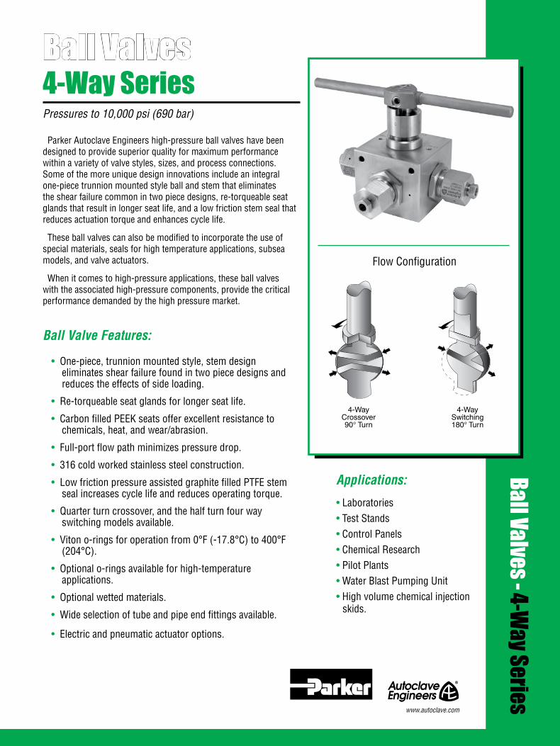
1All general terms and conditions of sale, including limitations of our liability, apply to all products and services sold.
Ball Valves4-Way SeriesPressures to 10,000 psi (690 bar)
Ball Valves - 4-Way Series
Flow Configuration
Applications:
• Laboratories• Test Stands• Control Panels• Chemical Research• Pilot Plants• Water Blast Pumping Unit• High volume chemical injection
skids.
4-WayCrossover
90 Turn
4-WaySwitching
180 Turn
4-WayCrossover90° Turn
4-WaySwitching180° Turn
www.autoclave.com
Parker Autoclave Engineers high-pressure ball valves have been designed to provide superior quality for maximum performance within a variety of valve styles, sizes, and process connections. Some of the more unique design innovations include an integral one-piece trunnion mounted style ball and stem that eliminates the shear failure common in two piece designs, re-torqueable seat glands that result in longer seat life, and a low friction stem seal that reduces actuation torque and enhances cycle life.
These ball valves can also be modified to incorporate the use of special materials, seals for high temperature applications, subsea models, and valve actuators.
When it comes to high-pressure applications, these ball valves with the associated high-pressure components, provide the critical performance demanded by the high pressure market.
Ball Valve Features:
• One-piece, trunnion mounted style, stem design eliminates shear failure found in two piece designs and reduces the effects of side loading.
• Re-torqueable seat glands for longer seat life.
• Carbon filled PEEK seats offer excellent resistance to chemicals, heat, and wear/abrasion.
• Full-port flow path minimizes pressure drop.
• 316 cold worked stainless steel construction.
• Low friction pressure assisted graphite filled PTFE stem seal increases cycle life and reduces operating torque.
• Quarter turn crossover, and the half turn four way switching models available.
• Viton o-rings for operation from 0°F (-17.8°C) to 400°F (204°C).
• Optional o-rings available for high-temperature applications.
• Optional wetted materials.
• Wide selection of tube and pipe end fittings available.
• Electric and pneumatic actuator options.

2 All general terms and conditions of sale, including limitations of our liability, apply to all products and services sold.
Ball Valves - 4-Way Series (3/8” Orifice)Pressures to 10,000 psi (690 bar) .375” (9.52mm) Orifice
MAWP @ Minimum Orifice Connection Room Temperature inches(mm)
SW500 10,000 psi (690 bar) .375 (9.52)
SF375CX20 10,000 psi (690 bar) .203 (5.16)
SF562CX20 10,000 psi (690 bar) .312 (7.92)
SF750CX20 10,000 psi (690 bar) .375 (9.52)
1/4” NPT 10,000 psi (690 bar) .375 (9.52)
3/8” NPT 10,000 psi (690 bar) .375 (9.52)
1/2” NPT 10,000 psi (690 bar) .375 (9.52)
Valve Cv=2.5
Ordering ProcedureFor complete information on available end connections and material options, see next page. 4-way ball valves are furnished complete with tube or pipe connections.
Typical catalog number: 4B 6 S 10 M9
6-3/8”(9.52 mm)
S -316SS
(For material options contact factory)
M9 - SF562CX20
(See Chart on next page)
M9End Connection
10Pressure
(X 1000 psi)
SMaterial
6Ball
OrificeDiameter
4BValveSeries
4B: 4-way crossover 4BS: 4-way switching
HT - High Temperature
XXXOptions
(Ball Valve Actuators, see next page)
MAWP: Maximum Allowable Working Pressure
NOTE: Ball valves are not recommended for critical gas applications such as Hydrogen, Helium or other small molecular gases.
STAINLESS STEEL HANDLE
STOPPING DEVICE
PACKING GLAND
LOCKING PIECE
SEAT GLAND
O-RING
CARBON FILLED PEEK SEATS BOTTOM BEARING
LOCKNUT
STEM SEAL
THRUST WASHER
ONE PIECE BALLAND STEM
BELLEVILLE WASHERS
O-RING
BELLEVILLE BACKUP
SET SCREW
SEAT RETAINER
TEMPERATURE ˚F
100 200 300 400 5000
5,000
10,000
15,000
PR
ES
SU
RE
PS
IG
PRESSURE TEMPERATURE RATINGS
SW500 NPT & SF CONNECTIONS
Pressure ratings are determined by the end connections chosen, see chart.
TEMPERATURE ˚C
(345)
(690)
(1034)(-18) (38) (93) (150) (204) (260)
PR
ES
SU
RE
BA
R
NPT connections rated 400˚F (204˚C) maximum.
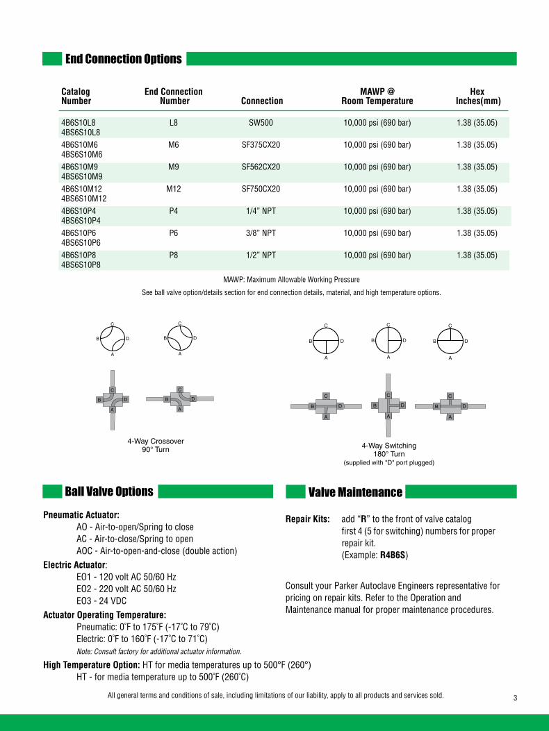
3All general terms and conditions of sale, including limitations of our liability, apply to all products and services sold.
End Connection Options
Catalog End Connection MAWP @ Hex Number Number Connection Room Temperature Inches(mm)
4B6S10L8 L8 SW500 10,000 psi (690 bar) 1.38 (35.05) 4BS6S10L8 4B6S10M6 M6 SF375CX20 10,000 psi (690 bar) 1.38 (35.05) 4BS6S10M6 4B6S10M9 M9 SF562CX20 10,000 psi (690 bar) 1.38 (35.05) 4BS6S10M9 4B6S10M12 M12 SF750CX20 10,000 psi (690 bar) 1.38 (35.05) 4BS6S10M12 4B6S10P4 P4 1/4” NPT 10,000 psi (690 bar) 1.38 (35.05) 4BS6S10P4 4B6S10P6 P6 3/8” NPT 10,000 psi (690 bar) 1.38 (35.05) 4BS6S10P6 4B6S10P8 P8 1/2” NPT 10,000 psi (690 bar) 1.38 (35.05) 4BS6S10P8
Ball Valve OptionsPneumatic Actuator: AO - Air-to-open/Spring to close AC - Air-to-close/Spring to open AOC - Air-to-open-and-close (double action)Electric Actuator: EO1 - 120 volt AC 50/60 Hz EO2 - 220 volt AC 50/60 Hz EO3 - 24 VDCActuator Operating Temperature: Pneumatic: 0˚F to 175˚F (-17˚C to 79˚C) Electric: 0˚F to 160˚F (-17˚C to 71˚C) Note: Consult factory for additional actuator information.
High Temperature Option: HT for media temperatures up to 500°F (260°) HT - for media temperature up to 500˚F (260˚C)
Repair Kits: add “R” to the front of valve catalog first 4 (5 for switching) numbers for proper repair kit. (Example: R4B6S)
Consult your Parker Autoclave Engineers representative for pricing on repair kits. Refer to the Operation and Maintenance manual for proper maintenance procedures.
Valve Maintenance
4 Way Crossover90 Turn
A
B
C
D
A
B
C
D
A
B
C
D
A
B
C
D
4-Way Switching180 Turn
(supplied with "D" port plugged)
A
B
C
D
A
B
C
D
A
B
C
D
A
B
C
D
A
B
C
D
A
B
C
D
MAWP: Maximum Allowable Working Pressure
See ball valve option/details section for end connection details, material, and high temperature options.
4-Way Crossover90° Turn 4-Way Switching
180° Turn(supplied with "D" port plugged)
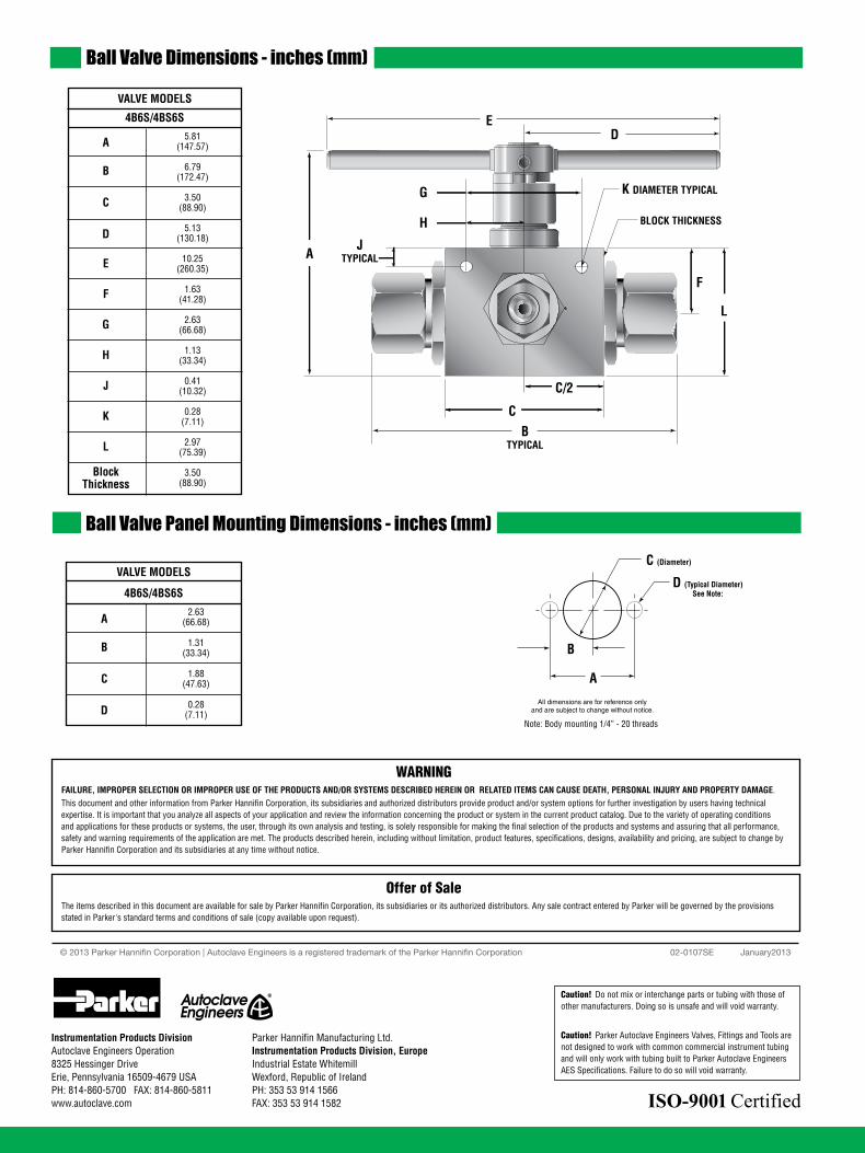
4 All general terms and conditions of sale, including limitations of our liability, apply to all products and services sold.
Ball Valve Dimensions - inches (mm)
Ball Valve Panel Mounting Dimensions - inches (mm)
5.81 (147.57)
6.79 (172.47)
3.50 (88.90)
5.13 (130.18)
10.25 (260.35)
1.63 (41.28)
2.63 (66.68)
1.13 (33.34)
0.41 (10.32)
0.28 (7.11)
2.97 (75.39)
3.50 (88.90)
2.63 (66.68)
1.31 (33.34)
1.88 (47.63)
0.28 (7.11)
C (Diameter)
D (Typical Diameter)
A
B
All dimensions are for reference only and are subject to change without notice.
See Note:
BTYPICAL
C
AJ
TYPICAL
H
G
ED
L
F
K DIAMETER TYPICAL
BLOCK THICKNESS
C/2
Note: Body mounting 1/4” - 20 threads
A
B
C
D
E
F
G
H
J
K
L
BlockThickness
A
B
C
D
VALVE MODELS
4B6S/4BS6S
VALVE MODELS
4B6S/4BS6S
02-0107SE January2013© 2013 Parker Hannifin Corporation | Autoclave Engineers is a registered trademark of the Parker Hannifin Corporation
Parker Hannifin Manufacturing Ltd. Instrumentation Products Division, Europe Industrial Estate WhitemillWexford, Republic of IrelandPH: 353 53 914 1566FAX: 353 53 914 1582
Instrumentation Products DivisionAutoclave Engineers Operation8325 Hessinger DriveErie, Pennsylvania 16509-4679 USAPH: 814-860-5700 FAX: 814-860-5811www.autoclave.com
WARNINGFAILURE, IMPROPER SELECTION OR IMPROPER USE OF THE PRODUCTS AND/OR SYSTEMS DESCRIBED HEREIN OR RELATED ITEMS CAN CAUSE DEATH, PERSONAL INJURY AND PROPERTY DAMAGE.This document and other information from Parker Hannifin Corporation, its subsidiaries and authorized distributors provide product and/or system options for further investigation by users having technical expertise. It is important that you analyze all aspects of your application and review the information concerning the product or system in the current product catalog. Due to the variety of operating conditions and applications for these products or systems, the user, through its own analysis and testing, is solely responsible for making the final selection of the products and systems and assuring that all performance, safety and warning requirements of the application are met. The products described herein, including without limitation, product features, specifications, designs, availability and pricing, are subject to change by Parker Hannifin Corporation and its subsidiaries at any time without notice.
Offer of SaleThe items described in this document are available for sale by Parker Hannifin Corporation, its subsidiaries or its authorized distributors. Any sale contract entered by Parker will be governed by the provisions stated in Parker's standard terms and conditions of sale (copy available upon request).
ISO-9001 Certified
Caution! Do not mix or interchange parts or tubing with those of other manufacturers. Doing so is unsafe and will void warranty.
Caution! Parker Autoclave Engineers Valves, Fittings and Tools are not designed to work with common commercial instrument tubing and will only work with tubing built to Parker Autoclave Engineers AES Specifications. Failure to do so will void warranty.
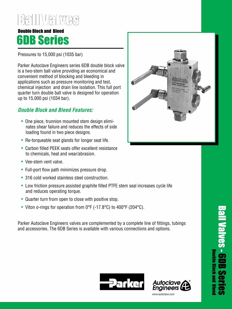
Parker Autoclave Engineers series 6DB double block valve is a two-stem ball valve providing an economical and convenient method of blocking and bleeding in applications such as pressure monitoring and test, chemical injection and drain line isolation. This full port quarter turn double ball valve is designed for operation up to 15,000 psi (1034 bar).
Double Block and Bleed Features:
• One piece, trunnion mounted stem design elimi- nates shear failure and reduces the effects of side loading found in two piece designs.
• Re-torqueable seat glands for longer seat life.
• Carbon filled PEEK seats offer excellent resistance to chemicals, heat and wear/abrasion.
• Vee-stem vent valve.
• Full-port flow path minimizes pressure drop.
• 316 cold worked stainless steel construction.
• Low friction pressure assisted graphite filled PTFE stem seal increases cycle life and reduces operating torque.
• Quarter turn from open to close with positive stop.
• Viton o-rings for operation from 0°F (-17.8°C) to 400°F (204°C).
Parker Autoclave Engineers valves are complemented by a complete line of fittings, tubings and accessories. The 6DB Series is available with various connections and options.
Ball Valves
Pressures to 15,000 psi (1035 bar)
6DB SeriesDouble Block and Bleed
Ball Valves - 6DB SeriesDouble Block and Bleed
www.autoclave.com
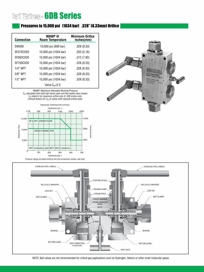
Ball Valves - 6DB SeriesPressures to 15,000 psi (1034 bar) .328” (8.33mm) Orifice
MAWP @ Minimum Orifice Connection Room Temperature inches(mm)
SW500 10,000 psi (690 bar) .328 (8.33)
SF375CX20 15,000 psi (1034 bar) .203 (5.16)
SF562CX20 15,000 psi (1034 bar) .312 (7.92)
SF750CX20 15,000 psi (1034 bar) .328 (8.33)
1/4” NPT 15,000 psi (1034 bar) .328 (8.33)
3/8” NPT 15,000 psi (1034 bar) .328 (8.33)
1/2” NPT 15,000 psi (1034 bar) .328 (8.33)
Valve Cv=2.3
MAWP: Maximum Allowable Working PressureCv calculated with both ball valves open and the needle valve closed.
Cv listed is for maximum orifice size of .328 inches only.Consult factory for Cv of valves with reduced orifice sizes.
NOTE: Ball valves are not recommended for critical gas applications such as Hydrogen, Helium or other small molecular gases.
TEMPERATURE ˚F
100 200 300 400 5000
5,000
10,000
15,000
PR
ES
SU
RE
PS
IG
PRESSURE TEMPERATURE RATINGS
SW500 CONNECTION
Pressure ratings are determined by the end connections chosen, see chart.
(1034)
(690)
(345)
TEMPERATURE ˚C
(-18) (38) (93) (150) (204) (260)P
RE
SS
UR
E B
AR
SF & NPT CONNECTIONS
NPT connections rated 400˚F (204˚C) maximum.
STAINLESS STEEL HANDLE
STOPPING DEVICE
PACKING GLAND
LOCKING PIECE
THRUST WASHER
SPRING ENERGIZEDSEALS
SEATS
STAINLESS STEEL HANDLE
BELLEVILLE WASHERS
LOCK NUT
SEAT GLANDS
BELLEVILLE WASHERS
LOCK NUT
SEAT GLANDS
BEARING
BOTTOM GLAND
BEARING
BOTTOM GLAND
VENT VALVE
O-RING O-RING
VENT CONNECTIONon back side
Connection Options
Catalog Tube Connection MAWP @ Hex Vent Connection Vent Number Number Connection Room Temperature Inches(mm) Number Connection
6DB10L8P4 L8 SW500 10,000 psi (690 bar) 1.38 (35.05) P4 1/4" NPT
6DB15M4M4 M4 SF250CX20 15,000 psi (1034 bar) 1.38 (35.05) M4 SF250CX20
6DB15M6M4 M6 SF375CX20 15,000 psi (1034 bar) 1.38 (35.05) M4 SF250CX20
6DB15M9M4 M9 SF562CX20 15,000 psi (1034 bar) 1.38 (35.05) M4 SF250CX20
6DB15M12M4 M12 SF750CX20 15,000 psi (1034 bar) 1.38 (35.05) M4 SF250CX20
6DB15M9P4 M9 SF562CX20 15,000 psi (1034 bar) 1.38 (35.05) P4 1/4" NPT
6DB15M16P4 M16 SF1000CX20 15,000 psi (1034 bar) 1.75 (44.45) P4 1/4" NPT
6DB15P4P4 P4 1/4" NPT 15,000 psi (1034 bar) 1.38 (35.05) P4 1/4" NPT
6DB15P6P4 P6 3/8" NPT 15,000 psi (1034 bar) 1.38 (35.05) P4 1/4" NPT
6DB15P8P4 P8 1/2" NPT 15,000 psi (1034 bar) 1.38 (35.05) P4 1/4" NPT
Ball Valve Options
High Temperature Option: HT - for media temperature up to 500˚F (260˚C)
See ball valve options/details for full description, connection details and high temperature options.
For material options consult factory.
Consult your Parker Autoclave Engineers representative for pricing on repair kits. Refer to the Operation and Mainte-nance manual for proper maintenance procedures.
Valve Maintenance
MAWP: Maximum Allowable Working Pressure
Ordering Procedure
M4Vent ConnectionM4 - SF250CX20(see chart below)
M9Tube
ConnectionM9 - SF562CX20(see chart below)
15Pressure
(X 1000 psi)
6DBValveSeries
6DB: 3/8 Double Block
For complete information on available end connections, see end connections options below. 6DB Series ball valves are furnished complete with tube or pipe connections.
Typical catalog number: 6DB 15 M9 M4 -XXX
XXXHT - High Temperature
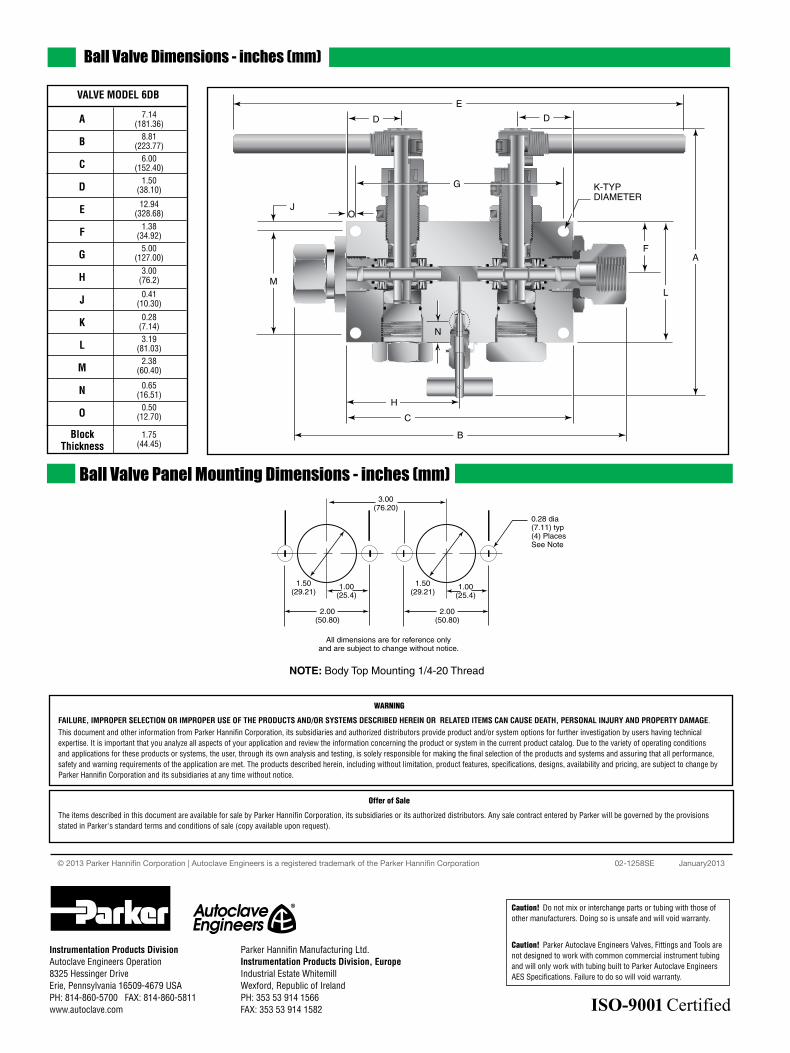
Ball Valve Dimensions - inches (mm)
VALVE MODEL 6DB
A
B
C
D
E
F
G
H
J
K
L
M
N
O
BlockThickness
7.14 (181.36) 8.81 (223.77) 6.00 (152.40) 1.50 (38.10)
12.94 (328.68) 1.38 (34.92) 5.00 (127.00) 3.00 (76.2)
0.41 (10.30)
0.28 (7.14) 3.19 (81.03) 2.38 (60.40)
0.65 (16.51) 0.50 (12.70)
1.75 (44.45)
E
D
A
B
J
G
L
F
K-TYPDIAMETER
C
M
D
O
H
N
All dimensions are for reference only and are subject to change without notice.
1.50(29.21)
3.00(76.20)
1.00(25.4)
1.50(29.21)
2.00(50.80)
1.00(25.4)
2.00(50.80)
0.28 dia(7.11) typ (4) PlacesSee Note
NOTE: Body Top Mounting 1/4-20 Thread
Ball Valve Panel Mounting Dimensions - inches (mm)
02-1258SE January2013© 2013 Parker Hannifin Corporation | Autoclave Engineers is a registered trademark of the Parker Hannifin Corporation
Parker Hannifin Manufacturing Ltd. Instrumentation Products Division, Europe Industrial Estate WhitemillWexford, Republic of IrelandPH: 353 53 914 1566FAX: 353 53 914 1582
Instrumentation Products DivisionAutoclave Engineers Operation8325 Hessinger DriveErie, Pennsylvania 16509-4679 USAPH: 814-860-5700 FAX: 814-860-5811www.autoclave.com
WARNING
FAILURE, IMPROPER SELECTION OR IMPROPER USE OF THE PRODUCTS AND/OR SYSTEMS DESCRIBED HEREIN OR RELATED ITEMS CAN CAUSE DEATH, PERSONAL INJURY AND PROPERTY DAMAGE.This document and other information from Parker Hannifin Corporation, its subsidiaries and authorized distributors provide product and/or system options for further investigation by users having technical expertise. It is important that you analyze all aspects of your application and review the information concerning the product or system in the current product catalog. Due to the variety of operating conditions and applications for these products or systems, the user, through its own analysis and testing, is solely responsible for making the final selection of the products and systems and assuring that all performance, safety and warning requirements of the application are met. The products described herein, including without limitation, product features, specifications, designs, availability and pricing, are subject to change by Parker Hannifin Corporation and its subsidiaries at any time without notice.
Offer of Sale
The items described in this document are available for sale by Parker Hannifin Corporation, its subsidiaries or its authorized distributors. Any sale contract entered by Parker will be governed by the provisions stated in Parker's standard terms and conditions of sale (copy available upon request).
ISO-9001 Certified
Caution! Do not mix or interchange parts or tubing with those of other manufacturers. Doing so is unsafe and will void warranty.
Caution! Parker Autoclave Engineers Valves, Fittings and Tools are not designed to work with common commercial instrument tubing and will only work with tubing built to Parker Autoclave Engineers AES Specifications. Failure to do so will void warranty.

Ball ValvesSubsea SeriesInternal Pressures to 20,000 psi (1379 bar) Water Depths to 12,500 ft (3810 meters)
Parker Autoclave Engineers subsea ball valves have been designed to fulfill the ever growing demand in the petroleum industry as well as the need for externally pressurized components in other markets. Utilizing the same design technology as the standard ball valve, the subsea design incorporates the necessary design alterations to provide a reliable externally pressurized valve for the subsea industry.
With the availability of fittings, tubing, and related equipment our ball valves can provide all your needs on high-pressure applica-tions above or below the surface.
Ball Valve Features:
• One-piece, trunnion mounted style, stem design eliminates shear failure found in two-piece designs.
• Re-torqueable seat glands for longer seat life.
• PEEK seats which offer excellent resistance to chemicals, heat, and wear/abrasion.
• Full-port flow path minimizes pressure drop.
• 316 cold worked stainless steel construction.
• Buna-N o-ring standard 250°F (121°C) max.
• Low friction pressure assisted graphite filled PTFE stem seal increases cycle life.
• Wide selection of tube and pipe end fittings available.
• Available to NACE MR-01-75.
• Optional wetted materials.
• Available in a number of flow configurations and port sizes.
Ball Valves - Subsea Series
Applications:
• Subsea hydraulic manifolds• Subsea control panels• Subsea trees
Adaptable for Remote Operated Vehicle (ROV) operation by customer
www.autoclave.com

The Parker Autoclave Engineers ball valves can be utilized to switch or isolate flow. The standard material of construction of the valve is 316 cold worked stainless steel with PEEK seats, graphite filled PTFE stem seal, and o-ring material as required by the process fluid.
The subsea ball valve design incorporates additional o-ring seals, which prevent the ingress of seawater into the valve which would adversely affect the operation of the valve as well as contaminate the process fluid. A significant feature of the subsea design is a thrust washer positioned under the stem preventing outside sea water from moving the stem from it’s aligned position.
Subsea ball valves are designed to facilitate operation by a Remote Operated vehicle (ROV). ROV operator assemblies are used for valve mounting and to provide positive stopping for precise 90° operation.
Various tube and pipe connections are available throughout a variety of valve configurations with standard port sizes from 3/16” to 1”. Contact Parker Autoclave Engineers technical sales support or your local distributor for more information on optional materials of construction, seal materials and ROV operator designs to fit your application requirements.
2

Ball Valves - 2-Way Subsea Series (1/4” Orifice)Pressures to 20,000 psi (1379 bar) .250” (6.35mm) Orifice
Ordering ProcedureFor complete information on available end connections, see next page. 2-way ball valves are furnished complete with tube or pipe connections. Standard valve has Buna-N o-rings [250°F (121°C)] max.
Typical catalog number: S2B 4 S 20 M9
4-1/4”(6.35mm)
S - 316SS
(For material options contact factory)
M9 - SF562CX20 (See Chart on
next page)
M9End Connection
20Pressure
(X 1000 psi)
SMaterial
4Ball
OrificeDiameter
S2BValveSeries
Subsea-2-way V - Viton: 400°F (204°C) maxEPDM - Ethylene Propylene: 250°F (121°C) max
XXXOptions
MAWP: Maximum Allowable Working PressureCv listed is for maximum orifice size of .250 inches only.
Consult factory for Cv of valves with reduced orifice sizes.
NOTE: Ball valves are not recommended for critical gas applications such as Hydrogen, Helium or other small molecular gases.
3
MAWP @ Minimum Orifice Connection Room Temperature inches(mm)
W125 15,000 psi (1034 bar) .094 (2.39)
SW250 15,000 psi (1034 bar) .128 (3.25)
SW375 15,000 psi (1034 bar) .250 (6.35)
SW500 10,000 psi (690 bar) .250 (6.35)
SF250CX20 20,000 psi (1379 bar) .109 (2.77)
SF375CX20 20,000 psi (1379 bar) .203 (5.16)
SF562CX20 20,000 psi (1379 bar) .250 (6.35)
F250C 20,000 psi (1379 bar) .094 (2.39)
F375C 20,000 psi (1379 bar) .125 (3.17)
F562C 20,000 psi (1379 bar) .188 (4.77)
1/8” NPT 15,000 psi (1034 bar) .250 (6.35)
1/4” NPT 15,000 psi (1034 bar) .250 (6.35)
3/8” NPT 15,000 psi (1034 bar) .250 (6.35)
1/2” NPT 15,000 psi (1034 bar) .250 (6.35)
Valve Cv=1.51
TEMPERATURE ˚F
100 200 300 400 5000
5,000
10,000
15,000
20,000
PR
ES
SU
RE
PS
IG
PRESSURE TEMPERATURE RATINGS
SF & F CONNECTIONS
W125, SW250, SW375, & NPT CONNECTIONS
SW500 CONNECTION
Pressure ratings are determined by the end connections chosen, see chart.
(1379)
(1034)
(690)
(345)
TEMPERATURE ˚C
(-18) (38) (93) (150) (204) (260)
PR
ES
SU
RE
BA
R
NPT connections rated 400˚F (204˚C) maximum.
PACKING GLAND
LOCKING PIECE
SEAT GLAND
O-RING
SEAT RETAINERBEARING
LOCKING PIECE
SPRING ENERGIZED SEAL
THRUST WASHER
ONE PIECE BALL STEM
PEEK SEATS
BOTTOM GLAND
O-RINGBOTTOM THRUST WASHER
O-RING
O-RING
Maximum temperature rating is determined by the o-ring material (see descriptions below).
Maximum pressure rating is determined by the end connection (see table above).

4Dimensions for reference only and subject to change.
End Connection Options
Catalog End Connection MAWP @ Hex Number Number Connection Room Temperature Inches(mm)
S2B4S15L2 L2 W125 15,000 psi (1034 bar) 1 (25.40)
S2B4S15L4 L4 SW250 15,000 psi (1034 bar) 1 (25.40)
S2B4S15L6 L6 SW375 15,000 psi (1034 bar) 1 (25.40)
S2B4S10L8 L8 SW500 10,000 psi (690 bar) 1 (25.40)
S2B4S20M4 M4 SF250CX20 20,000 psi (1379 bar) 1 (25.40)
S2B4S20M6 M6 SF375CX20 20,000 psi (1379 bar) 1 (25.40)
S2B4S20M9 M9 SF562CX20 20,000 psi (1379 bar) 1 (25.40)
S2B4S20H4 H4 F250C 20,000 psi (1379 bar) 1 (25.40)
S2B4S20H6 H6 F375C 20,000 psi (1379 bar) 1 (25.40)
S2B4S20H9 H9 F562C 20,000 psi (1379 bar) 1.38 (35.05)
S2B4S15P2 P2 1/8” NPT 15,000 psi (1034 bar) 1 (25.40)
S2B4S15P4 P4 1/4” NPT 15,000 psi (1034 bar) 1 (25.40)
S2B4S15P6 P6 3/8” NPT 15,000 psi (1034 bar) 1 (25.40)
S2B4S15P8 P8 1/2” NPT 15,000 psi (1034 bar) 1.38 (35.05)
MAWP: Maximum Allowable Working Pressure See ball valve option/details section for end connection details, material, and high temperature options.
Seat Gland
NOTE:1. MAWP (See Table)2. Maximum Sea Depth 12,500 FT (3811 meters)3. Maximum External Pressure 5,500 psi (379 bar)
0.216 ± 0.001 FLAT(5.48 ± .025)
Ø 0.249 ± 0.001(6.32 ± .025)
0.50 FLAT LG(12.7)
1.27(32.4)
Ø 0.28(7.1)
0.25(6.4)
0.43(10.9)
1.50(38.1)
4.18(106.3)
2.00(50.8)
0.31(7.7)
4.31(109.3)
0.81 HEX(20.6)
1.19(30.2)HEX
SEE SEATGLAND HEX
1.50(38.1)
0.75(19.1)
0.50(12.7)
1/4-20 THD
1.00(25.4)
SEE ENDCONNECTIONOPTIONS (both ends)
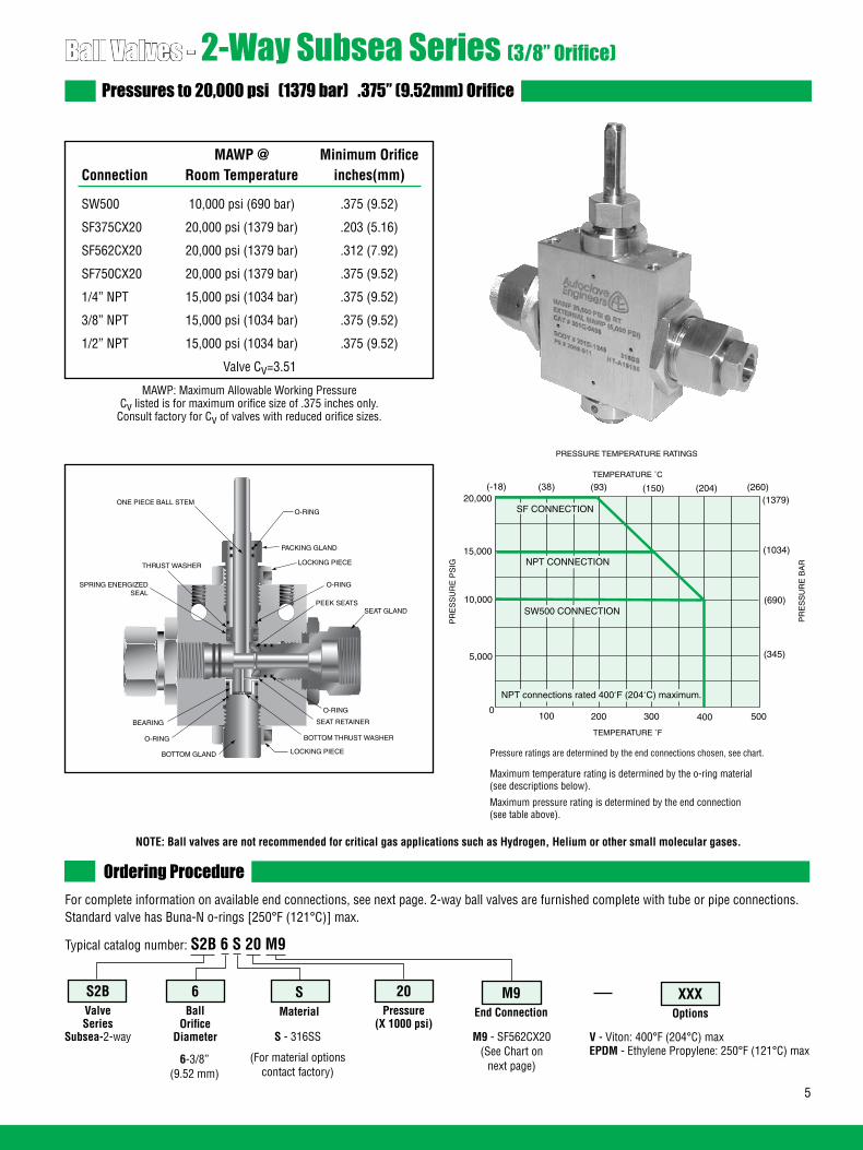
Dimensions for reference only and subject to change.
Ball Valves - 2-Way Subsea Series (3/8” Orifice)Pressures to 20,000 psi (1379 bar) .375” (9.52mm) Orifice
Ordering ProcedureFor complete information on available end connections, see next page. 2-way ball valves are furnished complete with tube or pipe connections.Standard valve has Buna-N o-rings [250°F (121°C)] max.
Typical catalog number: S2B 6 S 20 M9
6-3/8”(9.52 mm)
S - 316SS
(For material options contact factory)
M9 - SF562CX20 (See Chart on
next page)
M9End Connection
20Pressure
(X 1000 psi)
SMaterial
6Ball
OrificeDiameter
S2BValveSeries
Subsea-2-way
MAWP @ Minimum Orifice Connection Room Temperature inches(mm)
SW500 10,000 psi (690 bar) .375 (9.52)
SF375CX20 20,000 psi (1379 bar) .203 (5.16)
SF562CX20 20,000 psi (1379 bar) .312 (7.92)
SF750CX20 20,000 psi (1379 bar) .375 (9.52)
1/4” NPT 15,000 psi (1034 bar) .375 (9.52)
3/8” NPT 15,000 psi (1034 bar) .375 (9.52)
1/2” NPT 15,000 psi (1034 bar) .375 (9.52)
Valve Cv=3.51
XXXOptions
MAWP: Maximum Allowable Working PressureCv listed is for maximum orifice size of .375 inches only.
Consult factory for Cv of valves with reduced orifice sizes.
NOTE: Ball valves are not recommended for critical gas applications such as Hydrogen, Helium or other small molecular gases.
TEMPERATURE ˚F
100 200 300 400 5000
5,000
10,000
15,000
20,000
PR
ES
SU
RE
PS
IGPRESSURE TEMPERATURE RATINGS
SF CONNECTION
NPT CONNECTION
SW500 CONNECTION
Pressure ratings are determined by the end connections chosen, see chart.
(1379)
(1034)
(690)
(345)
TEMPERATURE ˚C
(-18) (38) (93) (150) (204) (260)
PR
ES
SU
RE
BA
R
NPT connections rated 400˚F (204˚C) maximum.
5
V - Viton: 400°F (204°C) maxEPDM - Ethylene Propylene: 250°F (121°C) max
Maximum temperature rating is determined by the o-ring material (see descriptions below).
Maximum pressure rating is determined by the end connection (see table above).
PACKING GLAND
LOCKING PIECE
SEAT GLAND
O-RING
SEAT RETAINERBEARING
LOCKING PIECE
SPRING ENERGIZEDSEAL
THRUST WASHER
PEEK SEATS
BOTTOM GLAND
O-RING BOTTOM THRUST WASHER
O-RING
O-RING
ONE PIECE BALL STEM

End Connection Options
Catalog End Connection MAWP @ Hex Number Number Connection Room Temperature Inches(mm)
S2B6S10L8 L8 SW500 10,000 psi (690 bar) 1.38 (35.05)
S2B6S20M6 M6 SF375CX20 20,000 psi (1379 bar) 1.38 (35.05)
S2B6S20M9 M9 SF562CX20 20,000 psi (1379 bar) 1.38 (35.05)
S2B6S20M12 M12 SF750CX20 20,000 psi (1379 bar) 1.38 (35.05)
S2B6S15P4 P4 1/4” NPT 15,000 psi (1034 bar) 1.38 (35.05)
S2B6S15P6 P6 3/8” NPT 15,000 psi (1034 bar) 1.38 (35.05)
S2B6S15P8 P8 1/2” NPT 15,000 psi (1034 bar) 1.38 (35.05)
MAWP: Maximum Allowable Working Pressure
See ball valve option/details section for end connection details, material, and high temperature options.
Seat Gland
6
NOTE:1. MAWP (See Table)2. Maximum Sea Depth 11,500 FT (3505 meters)3. Maximum External Pressure 5,000 psi (345 bar)
Dimensions for reference only and subject to change.
1.25(31.8)
1.03(26.2)
0.44(26.2)
5.78(146.8)
1.75” HEX(44.5)
5.53(140.3)
3.00(76.2)
0.76(19.2)
1.78(45.2)
3.28(83.3)
0.375 ± 0.001 SQUARE(9.35 ± 0.02)
0.44(11.1)
0.88(22.3)
2.50(63.5)
HEX0.94
(23.9)
0.44(11.1)
1.25(31.8)
1.38(35.1)
0.69(17.5)
1.38(34.9)BODY
THICKNESS
5/16-18 THRD.59” DEEP TYP(4) PLACES
SEE SEATGLAND HEX
SEE ENDCONNECTIONOPTIONS(both ends)
1.25(31.8)
1.03(26.2)
0.44(26.2)
5.78(146.8)
1.75” HEX(44.5)
5.53(140.3)
3.00(76.2)
0.76(19.2)
1.78(45.2)
3.28(83.3)
0.375 ± 0.001 SQUARE(9.35 ± 0.02)
0.44(11.1)
0.88(22.3)
2.50(63.5)
HEX0.94
(23.9)
0.44(11.1)
1.25(31.8)
1.38(35.1)
0.69(17.5)
1.38(34.9)BODY
THICKNESS
5/16-18 THRD.59” DEEP TYP(4) PLACES
SEE SEATGLAND HEX
SEE ENDCONNECTIONOPTIONS(both ends)
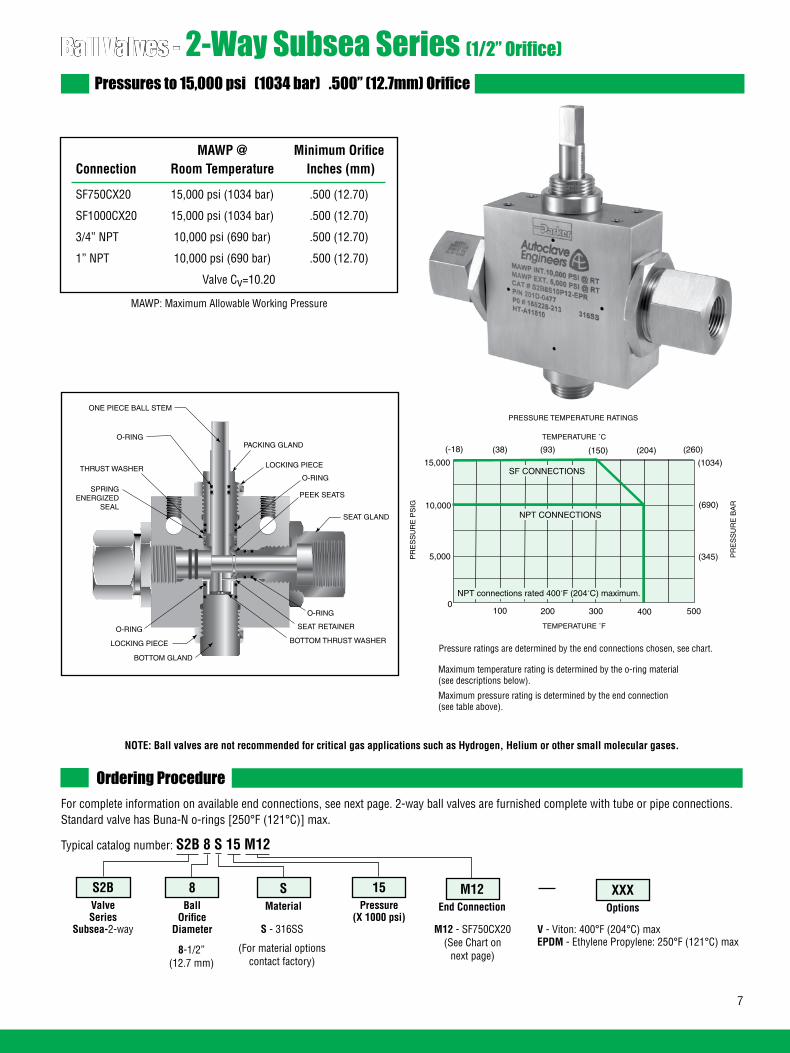
Ball Valves - 2-Way Subsea Series (1/2” Orifice)Pressures to 15,000 psi (1034 bar) .500” (12.7mm) Orifice
Ordering ProcedureFor complete information on available end connections, see next page. 2-way ball valves are furnished complete with tube or pipe connections.Standard valve has Buna-N o-rings [250°F (121°C)] max.
Typical catalog number: S2B 8 S 15 M12
8-1/2”(12.7 mm)
S - 316SS
(For material options contact factory)
M12 - SF750CX20 (See Chart on
next page)
M12End Connection
15Pressure
(X 1000 psi)
SMaterial
8Ball
OrificeDiameter
S2BValveSeries
Subsea-2-way
XXXOptions
NOTE: Ball valves are not recommended for critical gas applications such as Hydrogen, Helium or other small molecular gases.
7
MAWP @ Minimum Orifice Connection Room Temperature Inches (mm)
SF750CX20 15,000 psi (1034 bar) .500 (12.70)
SF1000CX20 15,000 psi (1034 bar) .500 (12.70)
3/4” NPT 10,000 psi (690 bar) .500 (12.70)
1” NPT 10,000 psi (690 bar) .500 (12.70)
Valve Cv=10.20
MAWP: Maximum Allowable Working Pressure
V - Viton: 400°F (204°C) maxEPDM - Ethylene Propylene: 250°F (121°C) max
Maximum temperature rating is determined by the o-ring material (see descriptions below).
Maximum pressure rating is determined by the end connection (see table above).
PACKING GLAND
LOCKING PIECE
SEAT GLAND
O-RING
SEAT RETAINER
LOCKING PIECE
SPRINGENERGIZED
SEAL
THRUST WASHER
ONE PIECE BALL STEM
PEEK SEATS
BOTTOM GLAND
O-RING
BOTTOM THRUST WASHER
O-RING
O-RING
TEMPERATURE ˚F
100 200 300 400 5000
5,000
10,000
15,000
PR
ES
SU
RE
PS
IGPRESSURE TEMPERATURE RATINGS
NPT CONNECTIONS
(1034)
(690)
(345)
TEMPERATURE ˚C
(-18) (38) (93) (150) (204) (260)
PR
ES
SU
RE
BA
R
SF CONNECTIONS
NPT connections rated 400˚F (204˚C) maximum.
Pressure ratings are determined by the end connections chosen, see chart.
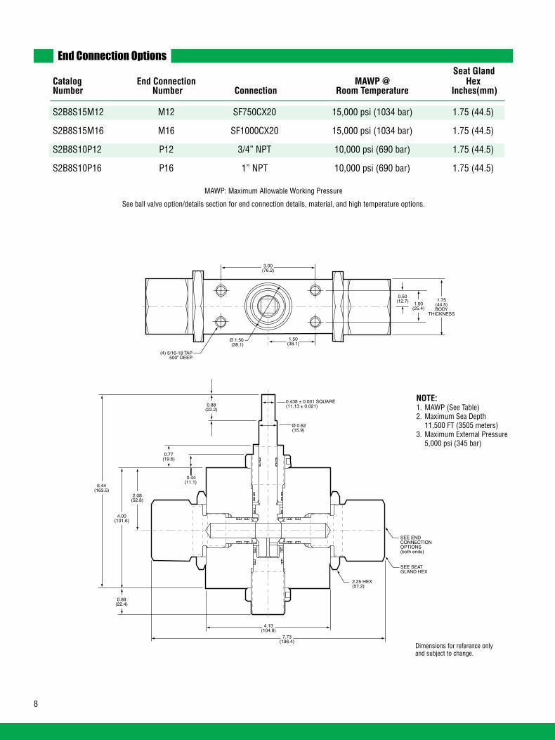
End Connection Options
Catalog End Connection MAWP @ Hex Number Number Connection Room Temperature Inches(mm)
S2B8S15M12 M12 SF750CX20 15,000 psi (1034 bar) 1.75 (44.5)
S2B8S15M16 M16 SF1000CX20 15,000 psi (1034 bar) 1.75 (44.5)
S2B8S10P12 P12 3/4” NPT 10,000 psi (690 bar) 1.75 (44.5)
S2B8S10P16 P16 1” NPT 10,000 psi (690 bar) 1.75 (44.5)
MAWP: Maximum Allowable Working Pressure
See ball valve option/details section for end connection details, material, and high temperature options.
Seat Gland
2.08(52.8)
4.00(101.6)
6.44(163.5)
0.77(19.6)
0.88(22.2)
0.88(22.4)
4.13(104.8)
7.73(196.4)
0.44(11.1)
0.438 ± 0.001 SQUARE(11.13 ± 0.021)
Ø 0.62(15.9)
(4) 5/16-18 TAP.500” DEEP
1.50(38.1)
1.00(25.4)
3.00(76.2)
Ø 1.50(38.1)
0.50(12.7) 1.75
(44.5)BODY
THICKNESS
2.25 HEX(57.2)
SEE SEATGLAND HEX
SEE ENDCONNECTIONOPTIONS(both ends)2.08
(52.8)
4.00(101.6)
6.44(163.5)
0.77(19.6)
0.88(22.2)
0.88(22.4)
4.13(104.8)
7.73(196.4)
0.44(11.1)
0.438 ± 0.001 SQUARE(11.13 ± 0.021)
Ø 0.62(15.9)
(4) 5/16-18 TAP.500” DEEP
1.50(38.1)
1.00(25.4)
3.00(76.2)
Ø 1.50(38.1)
0.50(12.7) 1.75
(44.5)BODY
THICKNESS
2.25 HEX(57.2)
SEE SEATGLAND HEX
SEE ENDCONNECTIONOPTIONS(both ends)
Dimensions for reference only and subject to change.
NOTE:1. MAWP (See Table)2. Maximum Sea Depth 11,500 FT (3505 meters)3. Maximum External Pressure 5,000 psi (345 bar)
8

Ball Valves - 2-Way Subsea Series (3/4” Orifice)Pressures to 15,000 psi (1034 bar) .750” (19mm) Orifice
Ordering ProcedureFor complete information on available end connections, see next page. 2-way ball valves are furnished complete with tube or pipe connections.Standard valve has Buna-N o-rings [250°F (121°C)] max.
Typical catalog number: S2B 12 S 15 M12
12-3/4”(19.05 mm)
S - 316SS
(For material options contact factory)
M12 - SF750CX10 (See Chart on
next page)
M12End Connection
15Pressure
(X 1000 psi)
SMaterial
12Ball
OrificeDiameter
S2BValveSeries
Subsea-2-way
XXXOptions
NOTE: Ball valves are not recommended for critical gas applications such as Hydrogen, Helium or other small molecular gases.
MAWP @ Minimum Orifice Connection Room Temperature Inches (mm)
SF750CX10 15,000 psi (1034 bar) .516 (13.10)
SF1000CX10 15,000 psi (1034 bar) .688 (17.47)
1/2” NPT 15,000 psi (1034 bar) .688 (17.47)
3/4” NPT 10,000 psi (690 bar) .75 (19.05)
1” NPT 10,000 psi (690 bar) .75 (19.05)
Valve Cv=21
MAWP: Maximum Allowable Working PressureCv listed is for maximum orifice size of .750 inch only.
Consult factory for Cv of valves with reduced orifice sizes.
V - Viton: 400°F (204°C) maxEPDM - Ethylene Propylene: 250°F (121°C) max
Maximum temperature rating is determined by the o-ring material (see descriptions below).
Maximum pressure rating is determined by the end connection (see table above).
Pressure ratings are determined by the end connections chosen, see chart.
9
TEMPERATURE ˚F
100 200 300 400 5000
5,000
10,000
15,000
PR
ES
SU
RE
PS
IG
PRESSURE TEMPERATURE RATINGS
3/4” & 1” NPT
(1034)
(690)
(345)
TEMPERATURE ˚C
(-18) (38) (93) (150) (204) (260)
PR
ES
SU
RE
BA
R
SF750CX, SF1000CX, 1/2” NPT
NPT connections rated 400˚F (204˚C) maximum.
PACKING GLAND
LOCKING PIECE
SEAT GLAND
O-RING
SEAT RETAINER
LOCKING PIECE
SPRINGENERGIZED
SEAL
THRUST WASHER
ONE PIECE BALL STEM
PEEK SEATS
BOTTOM GLAND
O-RING
BOTTOM THRUST WASHER
O-RING
O-RING

End Connection Options
Catalog End Connection MAWP @ Hex Number Number Connection Room Temperature Inches(mm)
S2B12S15M12 M12 SF750CX20 15,000 psi (1034 bar) 1.88 (47.8)
S2B12S15M16 M16 SF1000CX20 15,000 psi (1034 bar) 1.88 (47.8)
S2B12S15P8 P8 1/2” NPT 15,000 psi (1034 bar) 1.88 (47.8)
S2B12S10P12 P12 3/4” NPT 10,000 psi (690 bar) 1.88 (47.8)
S2B12S10P16 P16 1” NPT 10,000 psi (690 bar) 1.88 (47.8)
MAWP: Maximum Allowable Working Pressure
See ball valve option/details section for end connection details, material, and high temperature options.
Seat Gland
2.67(67.9)
5.31(134.9)
8.58(217.93)
.980(24.89)
1.50(38.10)
0.75(19.05)
4.50(114.30)
9.18(233.10)
0.50(12.70)
0.750 ± 0.001 SQUARE(19.05 ± 0.021)
.938(23.81)
(4) 3/8-16 TAP.625” DEEP
1.75(44.45)
1.50(38.10)
3.50(88.9)
2.25(57.2)
0.75(19.05) 3.00
(76.2)BODY
THICKNESS
2.25 HEX(57.2)
SEE SEATGLAND HEX
SEE ENDCONNECTIONOPTIONS(both ends)
Dimensions for reference only and subject to change.
NOTE:1. MAWP (See Table)2. Maximum Sea Depth 11,500 FT (3505 meters)3. Maximum External Pressure 5,000 psi (345 bar)
10
2.67(67.9)
5.31(134.9)
8.58(217.93)
.980(24.89)
1.50(38.10)
0.75(19.05)
4.50(114.30)
9.18(233.10)
0.50(12.70)
0.750 ± 0.001 SQUARE(19.05 ± 0.021)
.938(23.81)
(4) 3/8-16 TAP.625” DEEP
1.75(44.45)
1.50(38.10)
3.50(88.9)
2.25(57.2)
0.75(19.05) 3.00
(76.2)BODY
THICKNESS
2.25 HEX(57.2)
SEE SEATGLAND HEX
SEE ENDCONNECTIONOPTIONS(both ends)
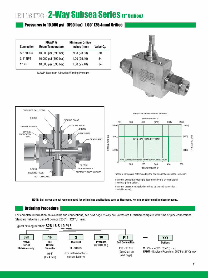
Ball Valves - 2-Way Subsea Series (1” Orifice)Pressures to 10,000 psi (690 bar) 1.00” (25.4mm) Orifice
Ordering ProcedureFor complete information on available end connections, see next page. 2-way ball valves are furnished complete with tube or pipe connections.Standard valve has Buna-N o-rings [250°F (121°C)] max.
Typical catalog number: S2B 16 S 10 P16
16-1”(25.4 mm)
S - 316SS
(For material options contact factory)
P16 - 1” NPT (See Chart on
next page)
P16End Connection
10Pressure
(X 1000 psi)
SMaterial
16Ball
OrificeDiameter
S2BValveSeries
Subsea-2-way
XXXOptions
NOTE: Ball valves are not recommended for critical gas applications such as Hydrogen, Helium or other small molecular gases.
MAWP @ Minimum Orifice Connection Room Temperature Inches (mm) Valve CV
SF1500CX 10,000 psi (690 bar) .938 (23.83) 30
3/4” NPT 10,000 psi (690 bar) 1.00 (25.40) 34
1” NPT 10,000 psi (690 bar) 1.00 (25.40) 34
MAWP: Maximum Allowable Working Pressure
V - Viton: 400°F (204°C) maxEPDM - Ethylene Propylene: 250°F (121°C) max
Maximum temperature rating is determined by the o-ring material (see descriptions below).
Maximum pressure rating is determined by the end connection (see table above).
Pressure ratings are determined by the end connections chosen, see chart.
11
PACKING GLAND
LOCKING PIECE
SEAT GLAND
O-RING
SEAT RETAINER
LOCKING PIECE
SPRINGENERGIZED
SEAL
THRUST WASHER
ONE PIECE BALL STEM
PEEK SEATS
BOTTOM GLAND
O-RING
BOTTOM THRUST WASHER
O-RING
O-RING
TEMPERATURE ˚F
100 200 300 400 5000
5,000
10,000
15,000
PR
ES
SU
RE
PS
IG
PRESSURE TEMPERATURE RATINGS
SF & NPT CONNECTIONS
(1034)
(690)
(345)
TEMPERATURE ˚C
(-18) (38) (93) (150) (204) (260)
PR
ES
SU
RE
BA
R
NPT connections rated 400˚F (204˚C) maximum.

End Connection Options
Catalog End Connection MAWP @ Hex Number Number Connection Room Temperature Inches(mm)
S2B16S10M24 M24 SF1500CX 10,000 psi (690 bar) 1.88 (47.75)
S2B16S10P12 P12 3/4” NPT 10,000 psi (690 bar) 1.88 (47.75)
S2B16S10P16 P16 1” NPT 10,000 psi (690 bar) 1.88 (47.75)
MAWP: Maximum Allowable Working Pressure
See ball valve option/details section for end connection details, material, and high temperature options.
Seat Gland
Dimensions for reference only and subject to change.
NOTE:1. MAWP (See Table)2. Maximum Sea Depth 11,500 FT (3505 meters)3. Maximum External Pressure 5,000 psi (345 bar)
12
2.67(67.9)
5.80(147.2)
9.96(253.0)
1.25(31.8)
1.75(44.5)
0.98(24.9)
5.19(131.8)
8.41(213.7)
0.50(12.70)
1.000 ± .005 SQUARE(25.40 ± 0.12)
1.25(31.7)
(4) 3/8-16 TAP.625” DEEP
2.00(50.8)
1.50(38.10)
4.00(101.6)
2.88(73.0)
0.75(19.05) 3.38
(85.7)BODY
THICKNESS
2.88 DIA(73.0)
SEE SEATGLAND HEX
SEE ENDCONNECTIONOPTIONS(both ends)2.67
(67.9)
5.80(147.2)
9.96(253.0)
1.25(31.8)
1.75(44.5)
0.98(24.9)
5.19(131.8)
8.41(213.7)
0.50(12.70)
1.000 ± .005 SQUARE(25.40 ± 0.12)
1.25(31.7)
(4) 3/8-16 TAP.625” DEEP
2.00(50.8)
1.50(38.10)
4.00(101.6)
2.88(73.0)
0.75(19.05) 3.38
(85.7)BODY
THICKNESS
2.88 DIA(73.0)
SEE SEATGLAND HEX
SEE ENDCONNECTIONOPTIONS(both ends)
Dimensions for P12 and P16 connections only. Contact facotry for M16 dimensions.
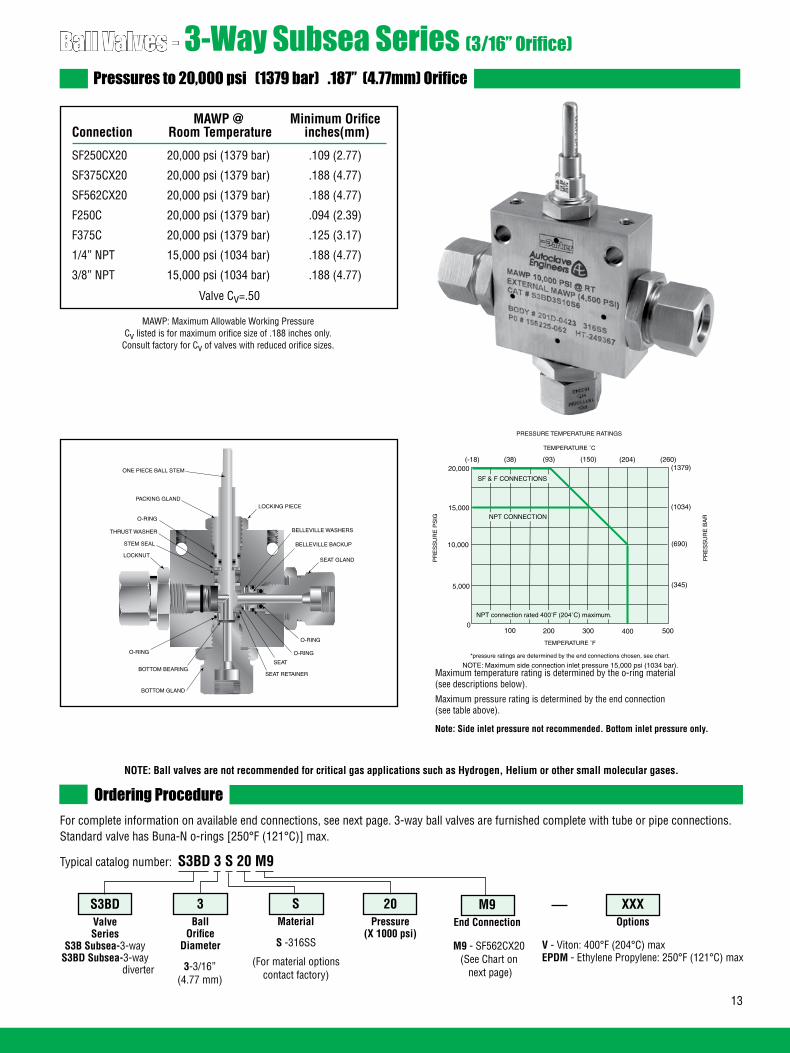
Ball Valves - 3-Way Subsea Series (3/16” Orifice)Pressures to 20,000 psi (1379 bar) .187” (4.77mm) Orifice
Ordering ProcedureFor complete information on available end connections, see next page. 3-way ball valves are furnished complete with tube or pipe connections.Standard valve has Buna-N o-rings [250°F (121°C)] max.
Typical catalog number: S3BD 3 S 20 M9
3-3/16”(4.77 mm)
S -316SS
(For material options contact factory)
M9 - SF562CX20 (See Chart on next page)
M9End Connection
20Pressure
(X 1000 psi)
SMaterial
3Ball
OrificeDiameter
MAWP @ Minimum Orifice Connection Room Temperature inches(mm)
SF250CX20 20,000 psi (1379 bar) .109 (2.77)
SF375CX20 20,000 psi (1379 bar) .188 (4.77)
SF562CX20 20,000 psi (1379 bar) .188 (4.77)
F250C 20,000 psi (1379 bar) .094 (2.39)
F375C 20,000 psi (1379 bar) .125 (3.17)
1/4” NPT 15,000 psi (1034 bar) .188 (4.77)
3/8” NPT 15,000 psi (1034 bar) .188 (4.77)
XXXOptions
MAWP: Maximum Allowable Working PressureCv listed is for maximum orifice size of .188 inches only.
Consult factory for Cv of valves with reduced orifice sizes.
NOTE: Ball valves are not recommended for critical gas applications such as Hydrogen, Helium or other small molecular gases.
Valve Cv=.50
Note: Side inlet pressure not recommended. Bottom inlet pressure only.
Maximum temperature rating is determined by the o-ring material (see descriptions below).
Maximum pressure rating is determined by the end connection (see table above).
V - Viton: 400°F (204°C) maxEPDM - Ethylene Propylene: 250°F (121°C) max
S3BDValveSeries
S3B Subsea-3-way S3BD Subsea-3-way
diverter
ONE PIECE BALL STEM
O-RING
O-RING
PACKING GLANDLOCKING PIECE
SEAT GLAND
O-RING
SEAT BOTTOM BEARING
LOCKNUT
STEM SEAL
THRUST WASHER BELLEVILLE WASHERS
SEAT RETAINER
BOTTOM GLAND
O-RING
BELLEVILLE BACKUP
13
TEMPERATURE ˚F
100 200 300 400 5000
5,000
10,000
15,000
20,000
PR
ES
SU
RE
PS
IGPRESSURE TEMPERATURE RATINGS
*pressure ratings are determined by the end connections chosen, see chart.
PR
ES
SU
RE
BA
R
(345)
(690)
(1034)
(1379)(-18) (38) (93) (150) (204) (260)
TEMPERATURE ˚C
NOTE: Maximum side connection inlet pressure 15,000 psi (1034 bar).
SF & F CONNECTIONS
NPT CONNECTION
NPT connection rated 400˚F (204˚C) maximum.

14
End Connection Options Catalog End Connection MAWP @ Hex Number Number Connection Room Temperature Inches(mm)
S3B3S15M4 M4 SF250CX20 15,000 psi (1034 bar) 1 (25.40) S3BD3S20M4 20,000 psi (1379 bar) S3B3S15M6 M6 SF375CX20 15,000 psi (1034 bar) 1 (25.40) S3BD3S20M6 20,000 psi (1379 bar) S3B3S15M9 M9 SF562CX20 15,000 psi (1034 bar) 1 (25.40) S3BD3S20M9 20,000 psi (1379 bar) S3B3S15H4 H4 F250C 15,000 psi (1034 bar) 1 (25.40) S3BD3S20H4 20,000 psi (1379 bar) S3B3S15H6 H6 F375C 15,000 psi (1034 bar) 1 (25.40) S3BD3S20H6 20,000 psi (1379 bar) S3B3S15P4 P4 1/4” NPT 15,000 psi (1034 bar) 1 (25.40) S3BD3S15P4 S3B3S15P6 P6 3/8” NPT 15,000 psi (1034 bar) 1 (25.40) S3BD3S15P6
See ball valve option/detail section for end connection details, material, and high temperature options.
*The Diverter Valve design permits inlet flow through the bottom port. Outlet flow may be diverted to either valve side port.
OPEN OPEN
*3-Way Diverter Valve 90° Turn
OPEN CLOSED
3-Way Ball Valve180 Turn
OPEN
*3-Way Diverter Valve90° Turn
3-Way Ball Valve180° Turn
Seat Gland
0.216 ± .001(5.49 ± .025)
1/4-20 TAP.41 DEEP
(2) PLACES
.041 TYP(10.41)
Ø 0.28 TYP(7.11)
0.94(23.87)
0.50 FLAT LGTH(12.7)
2.00(50.8)
1.50(38.1)
2.56(65.02)
1.28(32.5)
4.34(110.23)
2.50(63.50)
4.72(119.89)
1.19 HEX TYP(30.22)
1.00 HEX TYP(25.4)
1.00(25.4)
2.50(63.50)
1.25(31.75)
Ø 0.25 STEM REF(6.35)
1.00 THK BODY(25.4)
0.50(12.7)
SEE END CONNECTIONOPTONS(3 PLACES)
.249 ± .001(6.32 ± .025)
NOTE:1. MAWP (See Table)2. Maximum Sea Depth 10,300 FT (3140 meters)3. Maximum External Pressure 4,500 psi (310 bar)
Dimensions for reference only and subject to change.

Ball Valves - 3-Way Subsea Series (3/8” Orifice)Pressures to 10,000 psi (689 bar) .328” (8.33mm) Orifice
Ordering ProcedureFor complete information on available end connections, see next page. 3-way ball valves are furnished complete with tube or pipe connections.Standard valve has Buna-N o-rings [250°F (121°C)] max.
Typical catalog number: S3B 6 S 10 M9
6-3/8”(9.52 mm)
S -316SS
(For material options contact factory)
M9 - SF562CX20(See Chart on
next page)
M9End Connection
10Pressure
(X 1000 psi)
SMaterial
6Ball
OrificeDiameter
S3BValveSeries
S3B Subsea-3-way S3BD Subsea-3-way
diverter
XXXOptions
MAWP: Maximum Allowable Working PressureCv listed is for maximum orifice size of .328 inches only.
Consult factory for Cv of valves with reduced orifice sizes.
NOTE: Ball valves are not recommended for critical gas applications such as Hydrogen, Helium or other small molecular gases.
MAWP @ Minimum Orifice Connection Room Temperature inches(mm)
SW500 10,000 psi (690 bar) .328 (8.33)
SF375CX20 10,000 psi (690 bar) .203 (5.16)
SF562CX20 10,000 psi (690 bar) .312 (7.92)
SF750CX20 10,000 psi (690 bar) .328 (8.33)
1/4” NPT 10,000 psi (690 bar) .328 (8.33)
3/8” NPT 10,000 psi (690 bar) .328 (8.33)
1/2” NPT 10,000 psi (690 bar) .328 (8.33)
Valve Cv=2.1
ONE PIECE BALL STEM
O-RING
O-RING
PACKING GLAND
LOCKING PIECE
SEAT GLAND
O-RING
SEAT BOTTOM BEARING
LOCKNUT
STEM SEAL
THRUST WASHERBELLEVILLE WASHERS
SEAT RETAINER
BOTTOM GLAND
O-RING
BELLEVILLE BACKUP
V - Viton: 400°F (204°C) maxEPDM - Ethylene Propylene: 250°F (121°C) max
Note: Side inlet pressure not recommended. Bottom inlet pressure only.
Maximum temperature rating is determined by the o-ring material (see descriptions below).
Maximum pressure rating is determined by the end connection (see table above).
15
TEMPERATURE ˚F
100 200 300 400 5000
5,000
10,000
15,000
PR
ES
SU
RE
PS
IG
PRESSURE TEMPERATURE RATINGS
SF, SW500 & NPT CONNECTIONS
(345)
(690)
(1034)(260)
TEMPERATURE C
PR
ES
SU
RE
BA
R
(-18) (38) (93) (150) (204)
NPT connections rated 400˚F (204˚C) maximum.

16
End Connection Options
See ball valve option/details section for end connection details, material, and high temperature options.
*The Diverter Valve design permits inlet flow through the bottom port. Outlet flow may be diverted to either valve side port.
OPEN CLOSED
3-Way Ball Valve180 Turn
OPENOPEN OPEN
*3-Way Diverter Valve 90° Turn
MAWP: Maximum Allowable Working Pressure
*3-Way Diverter Valve90° Turn
3-Way Ball Valve180° Turn
Dimensions for reference only and subject to change.
NOTE:1. MAWP (See Table)2. Maximum Sea Depth 11,500 FT (3505 meters)3. Maximum External Pressure 5,000 psi (345 bar)
S3B6S10L8 L8 SW500 10,000 psi (690 bar) 1.38 (35.05) S3BD6S10L8 S3B6S10M6 M6 SF375CX20 10,000 psi (690 bar) 1.38 (35.05) S3BD6S10M6 S3B6S10M9 M9 SF562CX20 10,000 psi (690 bar) 1.38 (35.05) S3BD6S10M9 S3B6S10M12 M12 SF750CX20 10,000 psi (690 bar) 1.38 (35.05) S3BD6S10M12 S3B6S10P4 P4 1/4” NPT 10,000 psi (690 bar) 1.38 (35.05) S3BD6S10P4 S3B6S10P6 P6 3/8” NPT 10,000 psi (690 bar) 1.38 (35.05) S3BD6S10P6 S3B6S10P8 P8 1/2” NPT 10,000 psi (690 bar) 1.38 (35.05) S3BD6S10P8
3.03(77.0)
1.63(41.4)
2.06(52.3)
0.41 TYP(10.4)
0.81FLAT LENGTH
(20.6)
2.00(50.8)
1.00(25.4)
0.281 ± 0.0012 FLATS 180º APART(7.14 ± .025)
Ø 0.437 ± 0.001(11.1 ± .025)
Ø 0.28 HOLE(2) PLACES(7.1)
3.00(76.2)
5.74(145.8)
5.08(129.0)
1.38(35.1)
0.69(17.5)
1.00(25.4)
1.75” HEX(44.5)
1/4-20 THREAD(2) PLACES
0.281 FLATS REF.(7.1)
B
.66(16.8) .44
(11.2)
SEE SEATGLAND HEX
1.38(35.1)
SEE ENDCONNECTIONOPTIONS(3 PLACES)
1.28(32.5)
DETAIL B
Seat Gland Catalog End Connection MAWP @ Hex Number Number Connection Room Temperature Inches(mm)

Ball Valves - 3-Way Subsea Series (1/2” Orifice)Pressures to 10,000 psi (690 bar) .500” (12.7mm) Orifice
MAWP @ Minimum Orifice Connection Room Temperature inches(mm)
SF750CX20 10,000 psi (690 bar) .500 (12.70)
SF1000CX20 10,000 psi (690 bar) .500 (12.70)
3/4” NPT 10,000 psi (690 bar) .500 (12.70)
1” NPT 10,000 psi (690 bar) .500 (12.70)
Valve Cv=4.4
Ordering ProcedureFor complete information on available end connections, see next page. 3-way ball valves are furnished complete with tube or pipe connections.Standard valve has Buna-N o-rings [250°F (121°C)] max.
Typical catalog number: S3B 8 S 10 M12
8-1/2”(12.7 mm)
S -316SS
(For material options contact factory)
M12 - SF750CX20(See Chart on
next page)
M12End Connection
10Pressure
(X 1000 psi)
SMaterial
8Ball
OrificeDiameter
XXXOptions
MAWP: Maximum Allowable Working Pressure
NOTE: Ball valves are not recommended for critical gas applications such as Hydrogen, Helium or other small molecular gases.
Note: Side inlet pressure not recommended. Bottom inlet pressure only.
S3BValveSeries
S3B Subsea-3-way S3BD Subsea-3-way
diverter
V - Viton: 400°F (204°C) maxEPDM - Ethylene Propylene: 250°F (121°C) max
Maximum temperature rating is determined by the o-ring material (see descriptions below).
Maximum pressure rating is determined by the end connection (see table above).
1/2” 3 WAY SUBSEA BALL VALVE STEM
O-RING
O-RING
PACKING GLAND
LOCKING PIECE
SEAT GLAND
O-RING
SEAT
BOTTOM BEARING
LOCKNUT
STEM SEAL
THRUST WASHERBELLEVILLE WASHERS
SEAT RETAINER
BOTTOM GLAND
O-RING
BELLEVILLE BACKUP
17
TEMPERATURE ˚F
100 200 300 400 5000
5,000
10,000
15,000
PR
ES
SU
RE
PS
IG
PRESSURE TEMPERATURE RATINGS
NPT & SF CONNECTIONS
(345)
(690)
(1034)(260)
TEMPERATURE C
PR
ES
SU
RE
BA
R
(-18) (38) (93) (150) (204)
NPT connections rated 400˚F (204˚C) maximum.

18
End Connection Options
Catalog End Connection MAWP @ Hex Number Number Connection Room Temperature Inches(mm)
S3B8S10M12 M12 SF750CX20 10,000 psi (690 bar) 1.75 (44.5) S3BD8S10M12 S3B8S10M16 M16 SF1000CX20 10,000 psi (690 bar) 1.75 (44.5) S3BD8S10M16 S3B8S10P12 P12 3/4” NPT 10,000 psi (690 bar) 1.75 (44.5) S3BD8S10P12 S3B8S10P16 P16 1” NPT 10,000 psi (690 bar) 1.75 (44.5) S3BD8S10P16
See ball valve options for end connection details, material, and high temperature options.
*The Diverter Valve design permits inlet flow through the bottom port. Outlet flow may be diverted to either valve side port.
OPEN OPEN
*3-Way Diverter Valve 90° Turn
OPEN CLOSED
3-Way Ball Valve180 Turn
OPEN
MAWP: Maximum Allowable Working Pressure
*3-Way Diverter Valve90° Turn
3-Way Ball Valve180° Turn
Seat Gland
DETAIL B
2.32(58.9)
1.188(30.2)
FLAT LENGTH
0.50 TYP(12.7)
2.00(50.8)
3.62(91.9)
4.13(104.9)
SEE SEATGLAND HEX
1.50(38.1)
3.00(76.2)
Ø 0.686(17.4)
Ø 0.28(7.1)(2) PLACES
0.438 ± 0.001(11.1 ± .025)
SQUARE
B
7.77(197.4)
0.438 (11.1) REF
1.75(44.5)
0.88(22.4)
3.00(76.2)1.50
(38.1)
1/4-20 THREAD(2) PLACES
2.25” HEX(57.2)
SEE ENDCONNECTION OPTIONS(3 PLACES)
1.79(45.5)
Ø1.75(44.5)
.65(16.5) .44
(11.2)
Dimensions for reference only and subject to change.
NOTE:1. MAWP (See Table)2. Maximum Sea Depth 11,500 FT (3505 meters)3. Maximum External Pressure 5,000 psi (345 bar)

This page is blank
19

02-0108SE January2013© 2013 Parker Hannifin Corporation | Autoclave Engineers is a registered trademark of the Parker Hannifin Corporation
Parker Hannifin Manufacturing Ltd. Instrumentation Products Division, Europe Industrial Estate WhitemillWexford, Republic of IrelandPH: 353 53 914 1566FAX: 353 53 914 1582
Instrumentation Products DivisionAutoclave Engineers Operation8325 Hessinger DriveErie, Pennsylvania 16509-4679 USAPH: 814-860-5700 FAX: 814-860-5811www.autoclave.com
WARNINGFAILURE, IMPROPER SELECTION OR IMPROPER USE OF THE PRODUCTS AND/OR SYSTEMS DESCRIBED HEREIN OR RELATED ITEMS CAN CAUSE DEATH, PERSONAL INJURY AND PROPERTY DAMAGE.This document and other information from Parker Hannifin Corporation, its subsidiaries and authorized distributors provide product and/or system options for further investiga-tion by users having technical expertise. It is important that you analyze all aspects of your application and review the information concerning the product or system in the current product catalog. Due to the variety of operating conditions and applications for these products or systems, the user, through its own analysis and testing, is solely responsible for making the final selection of the products and systems and assuring that all performance, safety and warning requirements of the application are met. The products described herein, including without limitation, product features, specifications, designs, availability and pricing, are subject to change by Parker Hannifin Corporation and its subsidiaries at any time without notice.
Offer of SaleThe items described in this document are available for sale by Parker Hannifin Corporation, its subsidiaries or its authorized distributors. Any sale contract entered by Parker will begoverned by the provisions stated in Parker's standard terms and conditions of sale (copy available upon request).
ISO-9001 Certified
Caution! Do not mix or interchange parts or tubing with those of other manufacturers. Doing so is unsafe and will void warranty.
Caution! Parker Autoclave Engineers Valves, Fittings and Tools are not designed to work with common commercial instrument tubing and will only work with tubing built to Parker Autoclave Engineers AES Specifications. Failure to do so will void warranty.

1All general terms and conditions of sale, including limitations of our liability, apply to all products and services sold.
Ball ValvesActuatorsPneumatic Actuators Electric Actuators
Parker Autoclave Engineers ball valves can be supplied with either pneumatic or electric operators for automated or remote operation. Pneumatic and electric operators can be supplied with a variety of features and options. Operators are sized for each valve series to provide reliable and trouble free operation. Listed below are the operator features and available options.
Ball Valve Actuator Features/Options:
Pneumatic Operators
• Used for remote and automatic operation
• Air-to-open/spring-to-close
• Air-to-close/spring-to-open
• Air-to-open and close (double acting)
• Limit switches or limit switches with visual indicators available
• High temperature option available.
• Stainless steel housing for corrosive applications available.
• Optional solenoid valve available
• Standard anodized aluminum housing
• Optional epoxy coated housing available
Electric Operators
• Interface with control systems for automated operation and monitoring
• 120 & 220 VAC, 50/60 Hz standard
• 24VDC
• Explosion proof available
• CE mark available
Ball Valves - Actuators
www.autoclave.com

2 All general terms and conditions of sale, including limitations of our liability, apply to all products and services sold.
Ball Valves - ActuatorsPneumatic Operated Ball Valves
Add the suffix -AO, -AC or -AOC to the appropriate valve catalog number for a complete valve assembly
“A” “B” “C” “D” “E” “F” “G” “H” “I” “J” 2B4-AO/AC 6.69 2.56 2.50 1.25 1.00 0.50 0.28 1.14 2.50 1.58 80 psi (169.92) (65.02) (63.50) (31.75) (25.40) (12.70) (7.11) (28.95) (63.50) (40.13) (5.51 bar)
2B6-AO/AC 9.84 3.94 3.00 1.50 1.50 0.75 0.34 1.87 3.00 2.24 80 psi (249.93) (100.07) (76.20) (38.10) (25.40) (19.05) (8.63) (47.49) (76.20_) (56.89) (5.51 bar)
2B8-AO/AC 11.65 4.57 3.00 1.50 2.00 1.00 0.53 2.17 3.00 2.48 80 psi (259.91) (116.07) (76.20) (38.10) (50.80) (25.40) (13.46) (55.11) (76.20) (62.99) (5.51 bar)
3BD3-AO/AC 6.69 2.56 2.50 1.25 1.00 0.50 0.28 1.14 2.50 1.58 80 psi (169.92) (65.02) (63.50) (31.75) (25.40) (12.70) (7.11) (28.95) (63.50) (40.13) (5.51 bar)
3BD6-AO/AC 9.84 3.94 3.00 1.50 1.50 0.75 0.34 1.87 3.00 2.24 80 psi (249.93) (100.07) (76.20) (38.10) (25.40) (19.05) (8.63) (47.49) (76.20_) (56.89) (5.51 bar)
3BD8-AO/AC 11.65 4.57 3.00 1.50 2.00 1.00 0.53 2.17 3.00 2.48 80 psi (259.91) (116.07) (76.20) (38.10) (50.80) (25.40) (13.46) (55.11) (76.20) (62.99) (5.51 bar)
2B4-AOC 6.69 2.56 2.50 1.25 1.00 0.50 0.28 1.14 2.50 1.58 80 psi (169.92) (65.02) (63.50) (31.75) (25.40) (12.70) (7.11) (28.95) (63.50) (40.13) (5.51 bar)
2B6-AOC 7.95 3.07 3.00 1.50 1.50 0.75 0.34 1.40 3.00 1.77 80 psi (201.93) (77.97) (76.20) (38.10) (38.10) (19.05) (8.63) (35.56) (76.20_) (44.95) (5.51 bar)
2B8-AOC 9.84 3.94 3.00 1.50 2.00 1.00 0.53 1.87 3.00 2.24 80 psi (249.91) (100.07) (76.20) (38.10) (50.80) (25.40) (13.46) (47.49) (76.20) (56.89) (5.51 bar)
3BD3-AOC 6.69 2.56 2.50 1.25 1.00 0.50 0.28 1.14 2.50 1.58 80 psi (169.92) (65.02) (63.50) (31.75) (25.40) (12.70) (7.11) (28.95) (63.50) (40.13) (5.51 bar)
3BD6-AOC 7.95 3.07 3.00 1.50 1.50 0.75 0.34 1.40 3.00 1.77 80 psi (201.93) (77.97) (76.20) (38.10) (25.40) (19.05) (8.63) (35.56) (76.20_) (44.95) (5.51 bar)
3BD8-AOC 9.84 3.94 3.00 1.50 2.00 1.00 0.53 1.87 3.00 2.24 80 psi (249.91) (100.07) (76.20) (38.10) (50.80) (25.40) (13.46) (47.49) (76.20) (56.89) (5.51 bar)
VALVE SERIES
DIMENSION DATA - Inches (mm) MINIMUM REQUIRED
AIR PRESSURE
NOTE: • Maximum allowable air pressure is 150 psi (10.34) • Actuators operating temperature: 0°F to 175°F (-17°C to 79°C) • 1/8” NPT female air connector (*= 1/4” NPT) • High temperature actuator option available, consult factory • AO: Air to open/spring to close • Stainless steel housing actuator models available, consult factory • AC: Air to close/spring to open • Actuators available with limit switches and visual indicators. • AOC: Air to open/air to close (double acting) • Corrosion resistant anodized aluminum housing. • Epoxy coated housing available. • Solenoids availabe, direct or nipple mount.
"C"
"D"
"G" DIAMETER(2) Holes
"F""E"
"B"
"A"/2"A"
"I""I"/2
"J" "H"
*
*
NOTE: Operators 90° rotations standard. 180° options available upon request.

3All general terms and conditions of sale, including limitations of our liability, apply to all products and services sold.
"F""F/2"
Ball Valves - ActuatorsElectric Operated Ball Valves
Add the suffix -EO1, -EO2 or -EO3 to the appropriate valve catalog number for a complete valve assembly
NOTE: • EO1: Electric 120 VAC • For other voltages consult factory • EO2: Electric 220 VAC • Actuator operating temperature: 0°F to 160°F (-17°C to 71°C) • EO3: Electric 24 VDC • Corrosive resistant Zytel housing • CSA approved for NEMA 4 & 4X • Consult factory for epoxy option
"B"
"E" DIAMETER(2) Holes
"D""C"
"A"
VALVE SERIES
DIMENSION DATA - Inches (mm) VOLTAGE
“A” “B” “C” “D” “E” “F” 2B4-EO1 2.50 1.25 1.00 0.50 0.28 2.50 120 VAC 2B4-EO2 (63.50) (31.75) (25.40) (12.70) (7.11) (63.50) 240 VAC
2B6-EO1 3.00 1.50 1.50 0.75 0.34 3.00 120 VAC 2B6-EO2 (76.20) (38.10) (38.10) (19.05) (8.63) (76.20) 240 VAC
3BD3-EO1 2.50 1.25 1.00 0.50 0.28 2.50 120 VAC 3BD3-EO2 (63.50) (31.75) (25.40) (12.70) (7.11) (63.50) 240 VAC
3BD6-EO1 3.00 1.50 1.50 0.75 0.34 3.00 120 VAC 3BD6-EO2 (76.20) (38.10) (38.10) (19.05) (8.63) (76.20) 240 VAC
2B4-EO3 2.50 1.25 1.00 0.50 0.28 2.50 24 VDC (63.50) (31.75) (25.40) (12.70) (7.11) (63.50)
2B6-EO3 3.00 1.50 1.50 0.75 0.34 3.00 24 VDC (76.20) (38.10) (38.10) (19.05) (8.63) (76.20)
3BD3-EO3 2.50 1.25 1.00 0.50 0.28 2.50 24 VDC (63.50) (31.75) (25.40) (12.70) (7.11) (63.50)
3BD6-EO3 3.00 1.50 1.50 0.75 0.34 3.00 24 VDC (76.20) (38.10) (38.10) (19.05) (8.63) (76.20)
50/60 Hz
50/60 Hz
50/60 Hz
50/60 Hz
NOTE: Operators 90° rotations standard. 180° options available upon request.
* Contact factory for dimensions
*
*
*
**
*
**

4 All general terms and conditions of sale, including limitations of our liability, apply to all products and services sold.
Ball Valves - ActuatorsElectric Operated Ball Valves
Add the suffix -EO1, -EO2 or -EO3 to the appropriate valve catalog number for a complete valve assembly
NOTE:
• EO1: Electric 120 VAC • EO2: Electric 220 VAC• EO3: Electric 24 VDC• Explosion proof• Actuator operating temperature: 0°F to 160°F (-17°C to 71°C)• Powder coated aluminum housing• CE marked• UL listed & CSA approved for NEMA 4, 4x, 7 & 9• For other voltages consult factory
2.00 (50.80)1.00 (25.40)
0.53 (13.46)(2) HOLES
1.50(38.10)
3.00(76.20)
1.50(38.10)3.00
(76.20)
2B8-EO1 120 VAC
3BD8-EO1 120 VAC
2B8-EO2 220 VAC
3BD8-EO2 220 VAC
VALVE SERIES
VOLTAGE
50/60 HZ
VALVE SERIES
2B8-EO3 24 VDC
3BD8-EO3 24 VDC
2B8-EO3 24 VDC
3BD8-EO3 24 VDC
VOLTAGE
02-0109SE January2013© 2013 Parker Hannifin Corporation | Autoclave Engineers is a registered trademark of the Parker Hannifin Corporation
Parker Hannifin Manufacturing Ltd. Instrumentation Products Division, Europe Industrial Estate WhitemillWexford, Republic of IrelandPH: 353 53 914 1566FAX: 353 53 914 1582
Instrumentation Products DivisionAutoclave Engineers Operation8325 Hessinger DriveErie, Pennsylvania 16509-4679 USAPH: 814-860-5700 FAX: 814-860-5811www.autoclave.com
WARNINGFAILURE, IMPROPER SELECTION OR IMPROPER USE OF THE PRODUCTS AND/OR SYSTEMS DESCRIBED HEREIN OR RELATED ITEMS CAN CAUSE DEATH, PERSONAL INJURY AND PROPERTY DAMAGE.This document and other information from Parker Hannifin Corporation, its subsidiaries and authorized distributors provide product and/or system options for further investiga-tion by users having technical expertise. It is important that you analyze all aspects of your application and review the information concerning the product or system in the current product catalog. Due to the variety of operating conditions and applications for these products or systems, the user, through its own analysis and testing, is solely responsible for making the final selection of the products and systems and assuring that all performance, safety and warning requirements of the application are met. The products described herein, including without limitation, product features, specifications, designs, availability and pricing, are subject to change by Parker Hannifin Corporation and its subsidiaries at any time without notice.
Offer of SaleThe items described in this document are available for sale by Parker Hannifin Corporation, its subsidiaries or its authorized distributors. Any sale contract entered by Parker will begoverned by the provisions stated in Parker's standard terms and conditions of sale (copy available upon request).
NOTE: * Contact factory for dimensions
*
* *
**
*
* *
***
ISO-9001 Certified
Caution! Do not mix or interchange parts or tubing with those of other manufacturers. Doing so is unsafe and will void warranty.
Caution! Parker Autoclave Engineers Valves, Fittings and Tools are not designed to work with common commercial instrument tubing and will only work with tubing built to Parker Autoclave Engineers AES Specifications. Failure to do so will void warranty.
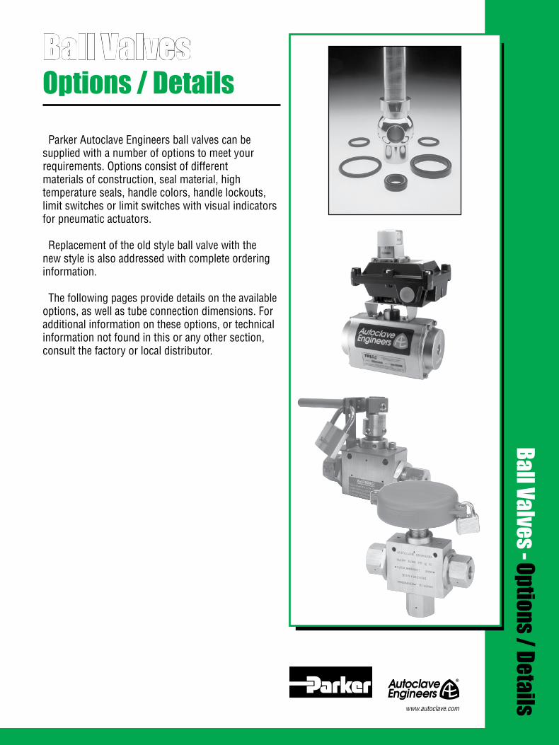
1All general terms and conditions of sale, including limitations of our liability, apply to all products and services sold.
Ball ValvesOptions / Details
Parker Autoclave Engineers ball valves can be supplied with a number of options to meet your requirements. Options consist of different materials of construction, seal material, high temperature seals, handle colors, handle lockouts, limit switches or limit switches with visual indicators for pneumatic actuators.
Replacement of the old style ball valve with the new style is also addressed with complete ordering information. The following pages provide details on the available options, as well as tube connection dimensions. For additional information on these options, or technical information not found in this or any other section, consult the factory or local distributor.
Ball Valves - Options / Details
www.autoclave.com
2 All general terms and conditions of sale, including limitations of our liability, apply to all products and services sold.
High Temperature Option Ball valves are available with alternate o-rings for high temperature operation. Standard Viton o-rings are replaced with Kalrez o-rings to increase the operating temperature to 500°F (260°C). To specify this option, add “-HT” to the catalog number as shown in the ball valve sections.
High temperature pneumatic valve actuators are also available. Consult factory with your application and for specific information.
Material Options Standard ball valves are constructed of 316 stainless steel. Other materials are available for specific applications upon request. NACE (MR0175-2002) approved materials for sour service can be supplied upon request. Consult factory for later NACE revisions and for the materials available as well as the temperature and pressure ratings.
Limit Switches or Limit Switches with Visual Indicators Pneumatic actuators are available with limit switches or limit switches with visual indicators. Consult the factory for information on these items or questions concerning your applications.
Handle Lockouts Handle lockouts are available to lockout ball valves in the open or closed position preventing unauthorized personnel from actuating valves during shutdowns or emergency situations.Note: To purchase ball valves with lockouts add -L to part number.Part numbers to purchase lockout separately:
2-Way Ball Valves 3-Way Ball Valves 1/4" 2B4-L 3/16" 3B3-L 3/8" 2B6-L 3/8" 3B6-L 1/2" 2B8-L 1/2" 3B8-L
For 3-way switching ball valves, consult factory.For 6DB (double block and bleed) valves use two 2B6-L lockouts.
Obsolete Ball Valves Ball valves complete with connection adapters are available for direct replacement of our older obsolete ball valve. The ball valve seat glands are designed to permit replacement without having to modify your existing tubing. To order valves for direct replacement add “-OS” to the end of the standard ball valve catalog number.Note: This applies only to the 1/4” 2-way ball valve.
Connection Detail Dimensions The following are reference dimensions for the tube connections used in the ball valves. For complete connection information see the Tools, Installation, Operation and Maintenance section in the Parker Autoclave Engineers Fluid Components complete catalog.
Ball Valves - Options / Details

3All general terms and conditions of sale, including limitations of our liability, apply to all products and services sold.
Tube Connection Dimensions - AE SpeedBite W *
Dimensions - Inches (mm)Connection
TypeA B C D E F G
1/8 W125 “Q” 0.332 3/8 -24 0.22 0.31 0.47 0.19 #30 0.128 (3.18) “Q” (8.43) (9.53) -24 (5.59) (7.87) (11.90) (4.83) #30 (3.25)
1/4 W250 11/16 3/4 -16 0.38 0.44 0.69 0.35 “F” 0.257 (6.35) (17.50) (19.10) -16 (9.65) (11.20) (17.50) (8.89) “F” (6.53)
3/8 W375 11/16 3/4 -16 0.38 0.44 0.69 0.48 “W” 0.386 (9.53) (17.50) (19.10) -16 (9.65) (11.20) (17.50) (12.20) “W” (9.80)
Dimensions - Inches (mm)Tube
Outside Diameterinches (mm)
Connection Type
A B C D E F G
1/4 SW250 29/64 1/2 -20 0.34 0.44 0.69 0.35 “F” 0.257 (6.35) (11.50) (12.7) -20 (8.64) (11.20) (17.50) (8.89) “F” (6.53) 3/8 SW375 37/64 5/8 -18 0.38 0.47 0.75 0.48 “W” 0.386 (19.50) (14.70) (15.90) -18 (9.65) (11.90) (19.10) (12.20) “W” (9.80)
1/2 SW500 3/4 13/16 -16 0.41 0.50 0.81 0.60 0.514 (12.70) (19.10) (20.60) -16 (10.50) (12.70) (20.60) (15.20) (13.100)
Note: All dimensions are shown for reference only and should not be considered as actual machine dimensions. * For port diameter please see orifice sizes for specific valves and fittings. All threads are manufactured to a class 2A or 2B fit.
For prompt service, Parker Autoclave Engineers stocks select products.
Consult factory
Tube Outside
Diameterinches (mm)
BTHREAD
ADRILL
F
24•
20•
E
DCG
*
BTHREAD
ADRILL
F
24•
20•
E
DCG
*
Tube Connection Dimensions - AE SpeedBite SW *
Dimensions - Inches (mm)Connection
TypeA B C D F
Tube Outside
Diameterinches (mm) B
THREAD
ADRILL
F
60•
Z = NPS Male Tap
DC
WEEPHOLE
5°
*
Tube Connection Dimensions - AE Medium Pressure SFCX **
1/4 SF250CX20 25/64 7/16 -20 0.28 0.50 0.19 (6.35) (9.92) (11.10) -20 (7.11) (12.70) (4.83)
3/8 SF375CX20 33/64 9/16 -18 0.38 0.62 0.31 (9.53) (13.10) (14.30) -18 (9.65) (15.70) (7.87)
9/16 SF562CX20 3/4 13/16 -16 0.44 0.75 0.50 (14.30) (19.10) (20.60) -16 (11.20) (19.10) (12.70)
3/4 SF750CX20 61/64 3/4 -14z 0.50 0.94 0.62 (19.10) (24.20) (19.10) -14z (12.70) (23.90) (15.70)
1 SF100CX20 1 -19/64 1-3/8 -12 0.81 1.31 0.88 (25.40) (32.90) (34.90) -12 (20.60) (33.30) (22.40)
1-1/2 SF1500CX 1-25/32 1-7/8-12 1.00 1.59 1.38 (38.10) (45.24) (47.63)-12 (25.40) (40.49) 34.93)
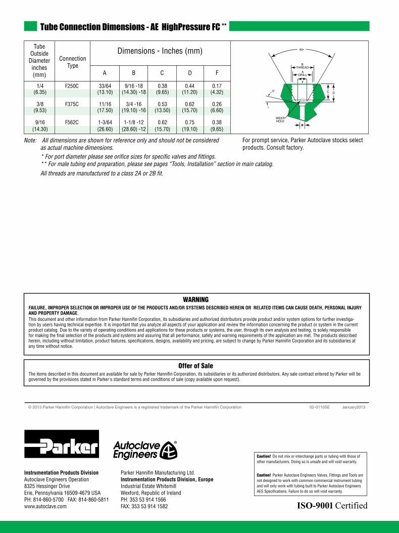
4 All general terms and conditions of sale, including limitations of our liability, apply to all products and services sold.
Note: All dimensions are shown for reference only and should not be considered as actual machine dimensions. * For port diameter please see orifice sizes for specific valves and fittings. ** For male tubing end preparation, please see pages “Tools, Installation” section in main catalog. All threads are manufactured to a class 2A or 2B fit.
Tube Connection Dimensions - AE HighPressure FC **
Dimensions - Inches (mm)Connection
TypeA B C D F
1/4 F250C 33/64 9/16 -18 0.38 0.44 0.17 (6.35) (13.10) (14.30) -18 (9.65) (11.20) (4.32)
3/8 F375C 11/16 3/4 -16 0.53 0.62 0.26 (9.53) (17.50) (19.10) -16 (13.50) (15.70) (6.60)
9/16 F562C 1-3/64 1-1/8 -12 0.62 0.75 0.38 (14.30) (26.60) (28.60) -12 (15.70) (19.10) (9.65)
For prompt service, Parker Autoclave stocks select products. Consult factory.
Tube Outside
Diameterinches (mm)
BTHREAD
ADRILL
F
60•
D
WEEPHOLE
C
*
5°
02-0110SE January2013© 2013 Parker Hannifin Corporation | Autoclave Engineers is a registered trademark of the Parker Hannifin Corporation
Parker Hannifin Manufacturing Ltd. Instrumentation Products Division, Europe Industrial Estate WhitemillWexford, Republic of IrelandPH: 353 53 914 1566FAX: 353 53 914 1582
Instrumentation Products DivisionAutoclave Engineers Operation8325 Hessinger DriveErie, Pennsylvania 16509-4679 USAPH: 814-860-5700 FAX: 814-860-5811www.autoclave.com
WARNINGFAILURE, IMPROPER SELECTION OR IMPROPER USE OF THE PRODUCTS AND/OR SYSTEMS DESCRIBED HEREIN OR RELATED ITEMS CAN CAUSE DEATH, PERSONAL INJURY AND PROPERTY DAMAGE.This document and other information from Parker Hannifin Corporation, its subsidiaries and authorized distributors provide product and/or system options for further investiga-tion by users having technical expertise. It is important that you analyze all aspects of your application and review the information concerning the product or system in the current product catalog. Due to the variety of operating conditions and applications for these products or systems, the user, through its own analysis and testing, is solely responsible for making the final selection of the products and systems and assuring that all performance, safety and warning requirements of the application are met. The products described herein, including without limitation, product features, specifications, designs, availability and pricing, are subject to change by Parker Hannifin Corporation and its subsidiaries at any time without notice.
Offer of SaleThe items described in this document are available for sale by Parker Hannifin Corporation, its subsidiaries or its authorized distributors. Any sale contract entered by Parker will begoverned by the provisions stated in Parker's standard terms and conditions of sale (copy available upon request).
ISO-9001 Certified
Caution! Do not mix or interchange parts or tubing with those of other manufacturers. Doing so is unsafe and will void warranty.
Caution! Parker Autoclave Engineers Valves, Fittings and Tools are not designed to work with common commercial instrument tubing and will only work with tubing built to Parker Autoclave Engineers AES Specifications. Failure to do so will void warranty.
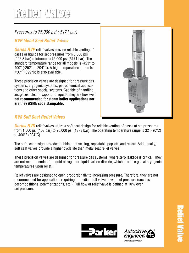
Pressures to 75,000 psi ( 5171 bar)
RVP Metal Seat Relief Valves
Series RVP relief valves provide reliable venting of gases or liquids for set pressures from 3,000 psi (206.8 bar) minimum to 75,000 psi (5171 bar). The standard temperature range for all models is -423° to 400° (-252° to 204°C). A high temperature option to 750°F (399°C) is also available.
These precision valves are designed for pressure gas systems, cryogenic systems, petrochemical applica-tions and other special systems. Capable of handling air, gases, steam, vapor and liquids, they are however, not recommended for steam boiler applications nor are they ASME code stampable.
RVS Soft Seat Relief Valves
Series RVS relief valves utilize a soft seat design for reliable venting of gases at set pressures from 1,500 psi (103 bar) to 20,000 psi (1378 bar). The operating temperature range is 32°F (0°C) to 400°F (204°C).
The soft seat design provides bubble tight sealing, repeatable pop-off, and reseat. Additionally, soft seat valves provide a higher cycle life than metal seat relief valves.
These precision valves are designed for pressure gas systems, where zero leakage is critical. They are not recommended for liquid nitrogen or liquid carbon dioxide, which produce gas at cryogenic temperatures upon relief.
Relief valves are designed to open proportionally to increasing pressure. Therefore, they are not recommended for applications requiring immediate full valve flow at set pressure (such as decompositions, polymerizations, etc.). Full flow of relief valve is defined at 10% over set pressure.
Relief Valve Relief Valve
www.autoclave.com
Materials: Standard models of Relief Valves are constructed of 316 stainless steel with selected compo-nents made of anti-galling stainless steel material for optimum economy and ruggedness.
Connections: All models except 30, 60, & 75 RVP series are designed with 9/16” Parker Autoclave Engi-neers Medium Pressure inlet connections. The 30 & 60 RVP have 3/8” high pressure connection, while the 75 RVP has a 5/16” high pressure connections. The outlet connection on all models is a female 3/4” NPT. While adapters to other sizes and connection types are available, they must be sized for specific flow re-quirements. See Adapter section.
Orifice Sizes: Orifice diameters range from .062 (1.57mm) to .312” (7.92mm).
Full Lift for Full Flow: These relief valves are designed to open as a function of increasing system pressure. Proper spring selection assures repeatability of opening, full lift and flow, and reseat pressures.
Reliability and Long Service Life: Materials engineering and stringent quality control procedures combine to assure the highest quality, reliability and service life. Each valve is preset and factory sealed to ensure proper valve operation.
High Set Pressure Capability: Unique seat construction plus over-the-nozzle guiding and proper selection of materials permits standard set pressures to 75,000 psi. (5171 bar)
Dependable Shut-off: Series RVP relief valves are designed to provide shut-off of liquids and gases under pressure to commercial tightness standards. Series RVS relief valves are designed to provide bubble tight shut off of gases.
Fewer Parts, Ease of Maintenance: Engineered to perform with fewer basic components, both RVP and RVS valves facilitate minimum stocking of spare parts and ease of maintenance. The combined angle seat in the RVP series eliminates the need for lapping in rework.
Special Requirements: Most models available with CE Mark. SOG option available upon request.
AE Relief Valves Features
All general terms and conditions of sale, including limitations of our liability, apply to all products and services sold.2

Relief Valves - RVP Metal Seat Relief Valves
Ordering Table and Specifications
InletConnection
Catalog*Number Outlet
Connection NPT
Pressure Rating psi (bar) @100°F (38°C)*OrficeDiameter
inches (mm)
All RVP models are designed primarily for thermal expansion or low volume relief applications at high pressures where flow is not critical. Thus, liquid curves for these models are not shown.
Note: Curves on this page are based on capacities of valves only and do not take tubing into account.
Caution should be exercised in proper selection of medium pressure tubing based on actual operating conditions. Two series available: 15,000 (1034.20 bar) and 20,000 (1380 bar).
Connection Size and Type
Minimum Setting
Maximum Setting
Maximum Back Pressure
RVP Series - See Figure 1
Dimension Inches (mm)
A
Figure 1 - RVP Series
Gas Flow Curves (SCFM of nitrogen)Consult factory for set pressures higher than 15,000 psi (1034 bar)
15,000(1034)
10,000(690)
5,000(344)
0
5 RVP
10 RVP
15 RVP 15 RVP setpressure range
10 RVP setpressure range
5 RVP setpressure range
1,000(28.32)
2,000(56.64)
3,000(84.96)
4,000(113.28)
SCFM (SCMM) @ 10% overpressure
Set
pre
ssur
e (p
sig@
100°
F)
Note: See back cover for options and ordering information.
All general terms and conditions of sale, including limitations of our liability, apply to all products and services sold. 3
For prompt service, Parker Autoclave Engineers stocks select products. Consult factory.
*Maximum pressure rating is based on the lowest rating of any component. Actual working pressure may be determined by tubing pressure rating, if lower.
Note: For pressure rating see selection chart.
Cap
Spring Washer
Spring
Lock Nut
Adjusting Bolt
Lock Nut
Gasket
Spindle
SpringCylinder
316 SSValve Body
316 SSSeat Gland
InletConnection
A
2.0050.80
Nitronic 60Plug Guide
316SS Plug
316SS Seat
1.1930.22
Mounting Holes.28” (7.11mm)
3.2582.55
2.5063.50
1.9449.28
3/4” NPTOutlet
5RVP9072 SF562CX 3/4 0.312 (7.92) 3,000 (206.84) 5,000 (344.73) 500 (34.47) 9.40 (238.76)
10RVP9072 SF562CX 3/4 0.250 (6.35) 5,000 (344.73) 10,000 (689.46) 500 (34.47) 9.40 (238.76)
15RVP9072 SF562CX 3/4 0.188 (4.78) 10,000 (689.46) 15,000 (1034.20) 500 (34.47) 9.40 (238.76)
20RVP9072 SF562CX 3/4 0.156 (3.96) 15,000 (1034.20) 20,000 (1378.93) 500 (34.47) 9.40 (238.76)
30RVP6072 F375C 3/4 0.125 (3.18) 20,000 (1378.93) 30,000 (2068.39) 500 (34.47) 9.52 (241.81)
45RVP9072 F562C 3/4 0.093 (2.36) 25,000 (1723.66) 45,000 (3102.59) 500 (34.47) 9.52 (241.81)
60RVP6072 F375C 3/4 0.078 (1.98) 30,000 (2068.39) 60,000 (4136.79) 500 (34.47) 9.52 (241.81)
75RVP5072 F312C150 3/4 0.062 (1.57) 37,000 (2551.02) 75,000 (5170.99) 500 (34.47) 9.83 (249.68)

Cap
Spring Washer
Spring
Lock Nut
Adjusting Bolt
Lock Nut
Gasket
Spindle
3/4” NPTOutlet
316 SSValve Body
316 SSSeat Gland
ArlonSoft Seat
Nitronic 60Plug Guide
A
InletConnection 2.00
50.80
1.1930.22
Mounting Holes.28” (7.11mm)
3.2582.55
2.5063.50
1.9449.28
Ordering Table and Specifications
Options: Parker Autoclave Engineers can supply various options on special order. A high temperature option is also available for temperatures to 750°F (399°C) for RVP models. Low temperature options are available for the soft seat valves.
To specify high temperature option:Add suffix “HT” for 750°F (399°C) high temperature option (RVP series only)
Caution: 1. AE relief valves are preset and factory sealed. Warranty is voided if seal is broken by customer. 2. Maximum system operating pressure should not exceed 90% of relief valve set pressure. Operating pressures in excess of this may cause weep age resulting in damage to the plug and seat.
Ordering Instructions: To permit prompt and correct responses to your order, we will require the following information: quantity, valve catalog number, service require-ments (liquid, gas & vapor), set pressure (PSIG - bar), and service temperature range.
Figure 2 - RVS Series
InletConnection
Catalog*Number Outlet
Connection NPT
Pressure Rating psi (bar) @100°F (38°C)OrficeDiameter
inches (mm)
Connection Size and Type
Minimum Setting
Maximum Setting
Maximum Back Pressure
RVS Series - See Figure 2
Dimension Inches (mm)
A
For prompt service, Parker Autoclave Engineers stocks select products. Consult factory.
*Maximum pressure rating is based on the lowest rating of any component. Actual working pressure may be determined by tubing pressure rating, if lower.
Note: For pressure rating see selection chart.
5RVS9072 SF562CX 3/4 0.312 (7.92) 1,500 (103.42) 5,000 (344.73) 500 (34.47) 9.40 (238.76)
10RVS9072 SF562CX 3/4 0.25 (6.35) 5,000 (344.73) 10,000 (689.46) 500 (34.47) 9.40 (238.76)
20RVS9072 SF562CX 3/4 0.156 (3.96) 10,000 (689.46) 20,000 (1378.93) 500 (34.47) 9.40 (238.76)
02-0129SE January2013© 2013 Parker Hannifin Corporation | Autoclave Engineers is a registered trademark of the Parker Hannifin Corporation
Parker Hannifin Manufacturing Ltd. Instrumentation Products Division, Europe Industrial Estate WhitemillWexford, Republic of IrelandPH: 353 53 914 1566FAX: 353 53 914 1582
Instrumentation Products DivisionAutoclave Engineers Operation8325 Hessinger DriveErie, Pennsylvania 16509-4679 USAPH: 814-860-5700 FAX: 814-860-5811www.autoclave.com
WARNING
FAILURE, IMPROPER SELECTION OR IMPROPER USE OF THE PRODUCTS AND/OR SYSTEMS DESCRIBED HEREIN OR RELATED ITEMS CAN CAUSE DEATH, PERSONAL INJURY AND PROPERTY DAMAGE.This document and other information from Parker Hannifin Corporation, its subsidiaries and authorized distributors provide product and/or system options for further investigation by users having technical expertise. It is important that you analyze all aspects of your application and review the information concerning the product or system in the current product catalog. Due to the variety of operating conditions and applications for these products or systems, the user, through its own analysis and testing, is solely responsible for making the final selection of the products and systems and assuring that all performance, safety and warning requirements of the application are met. The products described herein, including without limitation, product features, specifications, designs, availability and pricing, are subject to change by Parker Hannifin Corporation and its subsidiaries at any time without notice.
Offer of Sale
The items described in this document are available for sale by Parker Hannifin Corporation, its subsidiaries or its authorized distributors. Any sale contract entered by Parker will be governed by the provisions stated in Parker's standard terms and conditions of sale (copy available upon request).
ISO-9001 Certified
Caution! Do not mix or interchange parts or tubing with those of other manufacturers. Doing so is unsafe and will void warranty.
Caution! Parker Autoclave Engineers Valves, Fittings and Tools are not designed to work with common commercial instrument tubing and will only work with tubing built to Parker Autoclave Engineers AES Specifications. Failure to do so will void warranty.

Parker Autoclave Engineer’s offers special components designed to meet customer specific requirements.
The following pages provide a brief outline of our optional connections and valve styles. Other styles of connections are available such as flange, SAE, AE Easy-Union, or metric, upon request.
Manifolds are well suited for particular applications such as termination of common lines as a distri-bution source from a large line to several smaller ones. Parker Autoclave Engineers manifolds are made to customer specifications and can be rated up to 100,000 psi (6895 bar). Manifolds can be supplied with any number and variety of connec-tions, including our medium and high-pressure con-nections, NPT, SAE, BSP, clamp-style, and others.
Components are available in non-standard materials, and can be supplied with special testing, cleaning or other requirements.
Specialty components such as adapters and dielectric fittings are available upon request.
Contact your local sales representative for availability and pricing of custom components.
Custom Valves, Adapters & Manifolds
CustomValves, Adapters & Manifolds
www.autoclave.com

Custom Valves, Adapters & Manifolds
Parker Autoclave Engineers offers a product line of non-standard valves and fittings with alternate style connections. Military Style Connections According to military standards • MS16142 • MS33649 • MS33656Up to 1” (25.4mm) in size.
Tube or Pipe Socket Weld Weld connections up to 1” (25.4mm) in size.
Tube or Pipe Butt Weld Weld connections up to 1” (25.4mm) in size.
British Standard Pipe Threads
Special Adapters
All general terms and conditions of sale, including limitations of our liability, apply to all products and services sold.2
Parker Autoclave Engineers also offers a line of compo-nents that assist in adapting into and out of specialized connections with Parker Autoclave Engineers medium pressure products. Along with the adapters shown, Parker Autoclave Engineers can provide other special adapters to fill requirements. Contact your local sales representative for information.
Dielectric FittingsDielectric couplings isolate components from the effects of electrical current. Available as male/female coupling rated to 15,000 psi (1034 bar) with selected connection sizes. For more information contact local sales or the factory
Tube orpipe socket
weld
Military styleconnections
Pipe or tubebutt weld
AE Medium Pressure (Male)
KC105 - 2 Piece
KC105 - 1 Piece

All general terms and conditions of sale, including limitations of our liability, apply to all products and services sold. 3
Custom Valves, Adapters & Manifolds
Parker Autoclave Engineers medium and high pressure valves and fittings are available in a variety of special ma-terials and configurations to satisfy most process require-ments. Please refer to the Valve Options section for types of materials available and ordering information.Other custom valves available include large port valves for ammonia, urea and polyethylene production service, and Y style straight-thru valves designed to minimize pressure drop.Contact your local sales representative to find out more about these custom products. See the metric section in this catalog for our complete line of metric valves, fitting and tubing line.
Manifold Block
Clamp Style Manifolds
Parker Autoclave Engineers will design and build manifolds with clamp-type metal to metal seats to meet customer specific applications. Manifolds can be designed with vari-ous sizes of clamp type closure are rated in accordance with the maximum rating of the clamp type closure or other connections, whichever is lower. A wide variation of connections can be supplied to meet required applications. These manifolds are used anywhere multiple ports are needed. They are often used on high pressure liquid nitrogen pumping systems or other gas/liquid handling systems requiring high flow capacities with dependable seal integrity.
Metric, Special Material & Special Configuration Valves, Fittings & Tubing
Specialty pressure manifolds minimize space requirements and reduce the installation time necessary to plumb a pressure system. In addition, by reducing the number of components used in a system, manifolds also reduce the number of potential leak joints. Parker Autoclave Engineers will design and build pressure manifolds to meet specific installation, layout, and pressure requirements. These mani-folds are capable of withstanding pressures from vacuum to 100,000 psi (6895 bar), and are available in a variety of ma-terials and sizes. Among the pressure connections that can be incorporated are Parker Autoclave Engineers low, medium and high pressure, NPT, SAE, BSP and others. Transitions in system line sizes and tubing pressure can be accomplished through a specialty manifold. These manifolds are appropri-ate wherever pressure tubing systems are utilized.

02-0131SE January2013© 2013 Parker Hannifin Corporation | Autoclave Engineers is a registered trademark of the Parker Hannifin Corporation
Parker Hannifin Manufacturing Ltd. Instrumentation Products Division, Europe Industrial Estate WhitemillWexford, Republic of IrelandPH: 353 53 914 1566FAX: 353 53 914 1582
Instrumentation Products DivisionAutoclave Engineers Operation8325 Hessinger DriveErie, Pennsylvania 16509-4679 USAPH: 814-860-5700 FAX: 814-860-5811www.autoclave.com
WARNING
FAILURE, IMPROPER SELECTION OR IMPROPER USE OF THE PRODUCTS AND/OR SYSTEMS DESCRIBED HEREIN OR RELATED ITEMS CAN CAUSE DEATH, PERSONAL INJURY AND PROPERTY DAMAGE.This document and other information from Parker Hannifin Corporation, its subsidiaries and authorized distributors provide product and/or system options for further investigation by users having technical expertise. It is important that you analyze all aspects of your application and review the information concerning the product or system in the current product catalog. Due to the variety of operating conditions and applications for these products or systems, the user, through its own analysis and testing, is solely responsible for making the final selection of the products and systems and assuring that all performance, safety and warning requirements of the application are met. The products described herein, including without limitation, product features, specifications, designs, availability and pricing, are subject to change by Parker Hannifin Corporation and its subsidiaries at any time without notice.
Offer of Sale
The items described in this document are available for sale by Parker Hannifin Corporation, its subsidiaries or its authorized distributors. Any sale contract entered by Parker will be governed by the provisions stated in Parker's standard terms and conditions of sale (copy available upon request).
ISO-9001 Certified
Caution! Do not mix or interchange parts or tubing with those of other manufacturers. Doing so is unsafe and will void warranty.
Caution! Parker Autoclave Engineers Valves, Fittings and Tools are not designed to work with common commercial instrument tubing and will only work with tubing built to Parker Autoclave Engineers AES Specifications. Failure to do so will void warranty.
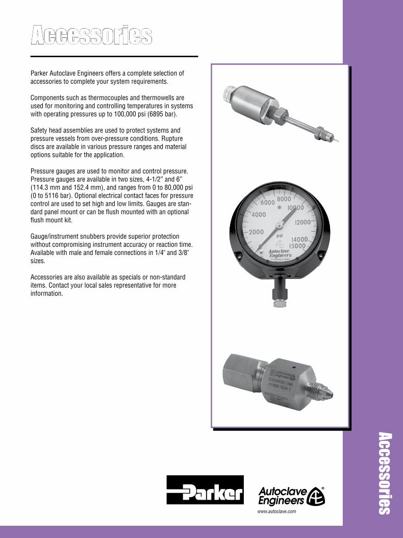
AccessoriesAccessories
Parker Autoclave Engineers offers a complete selection of accessories to complete your system requirements.
Components such as thermocouples and thermowells are used for monitoring and controlling temperatures in systems with operating pressures up to 100,000 psi (6895 bar).
Safety head assemblies are used to protect systems and pressure vessels from over-pressure conditions. Rupture discs are available in various pressure ranges and material options suitable for the application.
Pressure gauges are used to monitor and control pressure. Pressure gauges are available in two sizes, 4-1/2” and 6” (114.3 mm and 152.4 mm), and ranges from 0 to 80,000 psi (0 to 5116 bar). Optional electrical contact faces for pressure control are used to set high and low limits. Gauges are stan-dard panel mount or can be flush mounted with an optional flush mount kit.
Gauge/instrument snubbers provide superior protection without compromising instrument accuracy or reaction time. Available with male and female connections in 1/4" and 3/8" sizes. Accessories are also available as specials or non-standard items. Contact your local sales representative for more information.
www.autoclave.com

Accessories - Pencil-type ThermocouplesPressures to 15,000 psi (1034 bar)
Thermocouples provide reliable temperature measurement within a system.
The design permits installation of the element in direct contact with the fluid stream, thereby providing reliable temperature measurement. The quick-connector affords system flexibility. The thermocouple tip has a grounded-type junction.
MaterialsPrecision-molded plastic connectors have heavy duty, spring-loaded jack inserts for positive contact. The sheath is type 316 stainless steel with 316 SS ferrule and gland. We offer a choice of iron constantan (J) or chromel-alumel (K) type elements (please specify when ordering). Basic assembly includes 1/8” Parker Autoclave Engineers Speedbite connection with adapt-ers for other connection sizes.
Pressure/Temperature RatingsRatings to 15,000 psi (1034 bar) maximum working pressure. Temperature rating based on connection style. Low pressure Speedbite connection not recommended below 0°F (-17.8C) or above 650°F (343°C) Ordering InformationCatalog order numbers in the table refer to the complete as-sembly. Add suffix”J” for iron constantan element or “K” for chromel-alumel. To order a basic thermocouple with plug/jack assembly and connection (without through or angle block), change last digit in order number to “0” and specify sheath length if different from standard 3.62” (91.94 mm) length.
Ordering examples: TP4400K 6” (152.4 mm) denotes basic thermocouple to fit into a 1/4” Parker Autoclave Engineers SpeedBite connection with chromel-alumel element and 6” (152.4 mm) sheath. TP 4401K denotes the above unit com-plete with through-type block and standard 3.62” (91.94 mm) sheath.
2 All general terms and conditions of sale, including limitations of our liability, apply to all products and services sold.
Calibration Type Type of Thermocouple Temperature Range Comments
Iron (+) 32 - 1400°F Reducing atmoshphere recommended. Iron leg Constantan (-) (0 - 760°C) subject to oxidation to elevated temperatures- use larger gauge to compensate.
Chromel (+) -328 - 2300°F Well suited for oxidizing atmosphere. Most Alumel (-) (-200 - 1260°) commonly used calibration type.
J
K
Thermocouple Specification Table
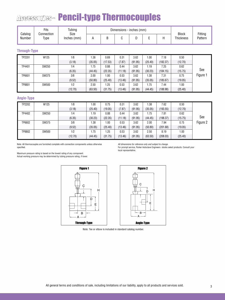
Accessories - Pencil-type Thermocouples
Note: All thermocouples are furnished complete with connection components unless otherwise specified.
Maximum pressure rating is based on the lowest rating of any component. Actual working pressure may be determined by tubing pressure rating, if lower.
All general terms and conditions of sale, including limitations of our liability, apply to all products and services sold. 3
Fits Tubing Catalog Connection Size Block Fitting Number Type Inches (mm) A B C D E H Thickness Pattern
Dimensions - inches (mm)
TP2201 W125 1/8 1.38 0.69 0.31 3.62 1.00 7.18 0.50 (3.18) (35.05) (17.53) (7.87) (91.95) (25.40) (182.37) (12.70) TP4401 SW250 1/4 1.75 0.88 0.44 3.62 1.19 7.25 0.62 (6.35) (44.45) (22.35) (11.18) (91.95) (30.23) (184.15) (15.75) TP6601 SW375 3/8 2.00 1.00 0.53 3.62 1.38 7.31 0.75 (9.52) (50.80) (25.40) (13.46) (91.95) (35.05) (185.67) (19.05) TP8801 SW500 1/2 2.50 1.25 0.53 3.62 1.75 7.44 1.00 (12.70) (63.50) (31.75) (13.46) (91.95) (44.45) (188.98) (25.40)
SeeFigure 1
Through-Type
TP2202 W125 1/8 1.00 0.75 0.31 3.62 1.38 7.62 0.50 (3.18) (25.40) (19.05) (7.87) (91.95) (35.05) (193.55) (12.70) TP4402 SW250 1/4 1.19 0.88 0.44 3.62 1.75 7.81 0.62 (6.35) (30.23) (22.35) (11.18) (91.95) (44.45) (198.37) (15.75) TP6602 SW375 3/8 1.38 1.00 0.53 3.62 2.00 7.94 0.75 (9.52) (35.05) (25.40) (13.46) (91.95) (50.80) (201.68) (19.05) TP8802 SW500 1/2 1.75 1.25 0.53 3.62 2.50 8.19 1.00 (12.70) (44.45) (31.75) (13.46) (91.95) (63.50) (208.03) (25.40)
SeeFigure 2
Angle-Type
All dimensions for reference only and subject to change.For prompt service, Parker Autoclave Engineers stocks select products. Consult your local representative.
Angle-TypeThrough-Type
Figure 2Figure 1
AB
C
D
E
H
AB
C
D
E
H
Note: Tee or elbow is included in standard catalog number.

4 All general terms and conditions of sale, including limitations of our liability, apply to all products and services sold.
Accessories - Sheath-type ThermocouplesPressures to 60,000 psi (4137 bar)
Thermocouples provide reliable temperature measurement within a fluid system.
Similar to low pressure thermocouples, this design also permits direct temperature monitoring at any point in a fluid system. The sheath type thermocouple features grounded junc-tion and rapid response - 100 milliseconds or less at 63.3% of a step charge. Temperature RatingRating to 2,000°F (1093°C) at tip of thermocouple. (Refer to adjacent Pressure/Temperature chart for elevated tempera-tures.) Minimum operating temperature 0°F (-17.8°C)
Sheath LengthDiffers for each size connection for optimum tip contact with fluid stream. MaterialsBodies are 15-5PH stainless steel. 316 sheath brazed into body with gold-nickel alloy brazing material. An aluminum terminal housing is threaded into the body for ready access to termi-nals. An o-ring seal provides moisture protection.
Ordering InformationTo order thermocouples for use in standard Parker Autoclave Engineers tees or crosses, use order numbers listed in table (fittings not included as standard). For custom length sheaths, to extend through a vessel wall or cover, calculate sheath length as follows:
1. Add vessel wall or cover thickness to the distance the sheath will extend into vessel. 2. When using a basic 1/4” Autoclave connection, subtract dimension “M” for proper sheath length to order. 3. For all other connection sizes, add dimension “N” to measurement obtained in step 1. 4. Order a custom length sheath by adding desired length in inches as suffix to order number.
Standard collar and gland are cold worked 316 SS for use up to 1200°F (649°C). When cold worked 316 SS collar and gland are used, the physical properties are permanently altered after use above 800°F (427°C).
CAUTION: While testing has shown O-rings to provide satis-factory service life, both cyclic and shelf life may vary widely with differing service conditions, properties of reactants, pressure and temperature cycling, and age of the O-ring. FREQUENT INSPECTION SHOULD BE MADE to detect any deterioration, and O-rings replaced as required.
CAUTION: See appropriate pressure section in reference to proper selection of tubing.
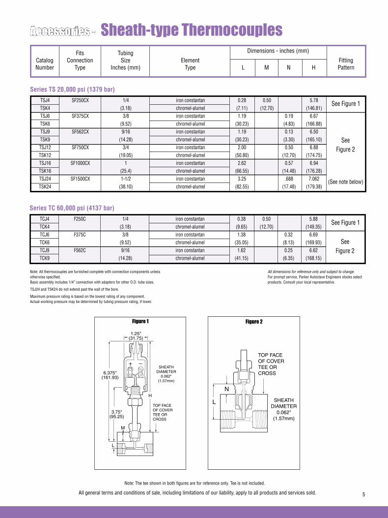
All general terms and conditions of sale, including limitations of our liability, apply to all products and services sold. 5
Accessories - Sheath-type Thermocouples
Note: All thermocouples are furnished complete with connection components unless otherwise specified. Basic assembly includes 1/4” connection with adapters for other O.D. tube sizes.
TSJ24 and TSK24 do not extend past the wall of the bore.
Maximum pressure rating is based on the lowest rating of any component. Actual working pressure may be determined by tubing pressure rating, if lower.
Fits Tubing Catalog Connection Size Element Fitting Number Type Inches (mm) Type L M N H Pattern
TSJ4 SF250CX 1/4 iron constantan 0.28 0.50 5.78 TSK4 (3.18) chromel-alumel (7.11) (12.70) (146.81) TSJ6 SF375CX 3/8 iron constantan 1.19 0.19 6.67 TSK6 (9.52) chromel-alumel (30.23) (4.83) (166.88) TSJ9 SF562CX 9/16 iron constantan 1.19 0.13 6.50 TSK9 (14.28) chromel-alumel (30.23) (3.30) (165.10) TSJ12 SF750CX 3/4 iron constantan 2.00 0.50 6.88 TSK12 (19.05) chromel-alumel (50.80) (12.70) (174.75) TSJ16 SF1000CX 1 iron constantan 2.62 0.57 6.94 TSK16 (25.4) chromel-alumel (66.55) (14.48) (176.28) TSJ24 SF1500CX 1-1/2 iron constantan 3.25 .688 7.062 TSK24 (38.10) chromel-alumel (82.55) (17.48) (179.38)
SeeFigure 2
Series TS 20,000 psi (1379 bar)
All dimensions for reference only and subject to change.For prompt service, Parker Autoclave Engineers stocks select products. Consult your local representative.
Dimensions - inches (mm)
TCJ4 F250C 1/4 iron constantan 0.38 0.50 5.88 TCK4 (3.18) chromel-alumel (9.65) (12.70) (149.35) TCJ6 F375C 3/8 iron constantan 1.38 0.32 6.69 TCK6 (9.52) chromel-alumel (35.05) (8.13) (169.93) TCJ9 F562C 9/16 iron constantan 1.62 0.25 6.62 TCK9 (14.28) chromel-alumel (41.15) (6.35) (168.15)
SeeFigure 2
Series TC 60,000 psi (4137 bar)
Figure 2Figure 1
L
H
M
1.25"(31.75)
SHEATHDIAMETER
0.062" (1.57mm)
TOP FACEOF COVERTEE OR CROSS
6.375"(161.93)
3.75"(95.25)
L SHEATHDIAMETER
0.062" (1.57mm)
TOP FACEOF COVERTEE OR CROSS
N
See Figure 1
See Figure 1
Note: The tee shown in both figures are for reference only. Tee is not included.
(See note below)
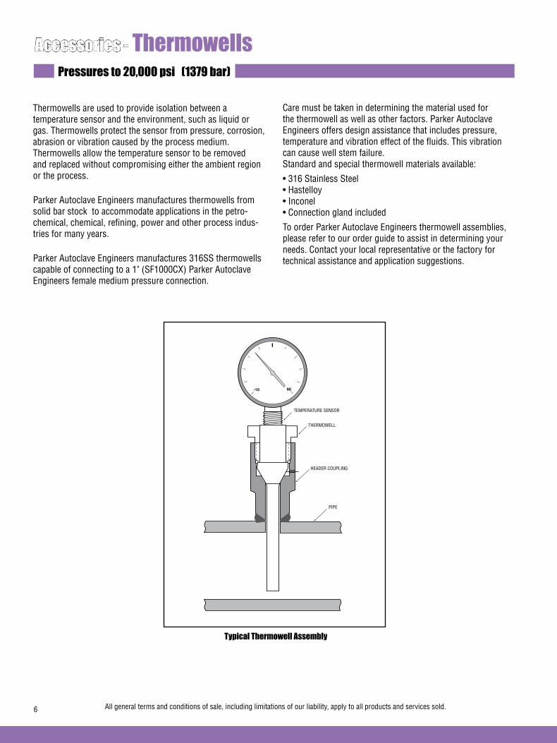
6 All general terms and conditions of sale, including limitations of our liability, apply to all products and services sold.
Accessories - ThermowellsPressures to 20,000 psi (1379 bar)
Thermowells are used to provide isolation between a temperature sensor and the environment, such as liquid or gas. Thermowells protect the sensor from pressure, corrosion, abrasion or vibration caused by the process medium. Thermowells allow the temperature sensor to be removed and replaced without compromising either the ambient region or the process.
Parker Autoclave Engineers manufactures thermowells from solid bar stock to accommodate applications in the petro-chemical, chemical, refining, power and other process indus-tries for many years.
Parker Autoclave Engineers manufactures 316SS thermowells capable of connecting to a 1" (SF1000CX) Parker Autoclave Engineers female medium pressure connection.
Care must be taken in determining the material used for the thermowell as well as other factors. Parker Autoclave Engineers offers design assistance that includes pressure, temperature and vibration effect of the fluids. This vibration can cause well stem failure.Standard and special thermowell materials available:
• 316 Stainless Steel• Hastelloy• Inconel• Connection gland included
To order Parker Autoclave Engineers thermowell assemblies, please refer to our order guide to assist in determining your needs. Contact your local representative or the factory for technical assistance and application suggestions.
Typical Thermowell Assembly
TEMPERATURE SENSOR
THERMOWELL
HEADER COUPLING
PIPE
-10 90
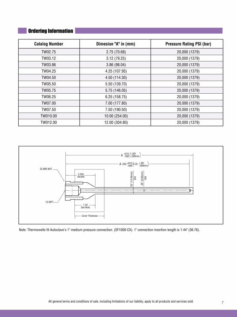
Ordering Information
Catalog Number Dimesion "A" in (mm) Pressure Rating PSI (bar)
TW02.75 2.75 (70.68) 20,000 (1379)
TW03.12 3.12 (79.25) 20,000 (1379)
TW03.86 3.86 (98.04) 20,000 (1379)
TW04.25 4.25 (107.95) 20,000 (1379)
TW04.50 4.50 (114.30) 20,000 (1379)
TW05.50 5.50 (139.70) 20,000 (1379)
TW05.75 5.75 (146.05) 20,000 (1379)
TW06.25 6.25 (158.75) 20,000 (1379)
TW07.00 7.00 (177.80) 20,000 (1379)
TW07.50 7.50 (190.50) 20,000 (1379)
TW010.00 10.00 (254.00) 20,000 (1379)
TW012.00 12.00 (304.80) 20,000 (1379)
All general terms and conditions of sale, including limitations of our liability, apply to all products and services sold. 7
A +015-.000
+.381-.000mm
A +015-.000
+.381-.000mm
-250 6.35
1/2 NPT
.53”
(13.
46m
m)
.26”
(6.6
0mm
)DI
A
DIA
GLAND NUT
2.350(59.69)
1.44See Note
Cover Thickness
Note: Thermowells fit Autoclave's 1" medium pressure connection. (SF1000-CX). 1" connection insertion length is 1.44" (36.76).

Accessories - Universal Safety HeadsPressures to 110,000 psi (7584 bar)
Safety Heads/Rupture Discs - Safety Heads and Rupture Discs offer an economical and dependable relief port to guard against system over-pressure.
Parker Autoclave Engineers offers universal safety heads in three series compatible in orifice size and maximum pressure rating with Parker Autoclave Low Pressure, Medium Pressure and High Pressure valves, fittings and tubing.
Parker Autoclave Engineers Low Pressure Series SS: Parker Autoclave SpeedBite Ermeto-type tube connection, maximum rupture pressures to 15,000 psi (1034 bar).
Parker Autoclave Engineers Medium Pressure Series CSX: Parker Autoclave Medium-Pressure coned-and-threaded tube connection, maximum rupture pressures to 20,000 psi (1379 bar).
Parker Autoclave Engineers High Pressure Series CS: Parker Autoclave High Pressure coned-and-threaded tube connection, maximum rupture pressure to 110,000 psi (7584 bar).
The 3/16F style features a 3/16” blow-out diameter and a flat seat which can be ordered in pressure range from 200 to 27,000 psi (13.8 to 1862 bar).
The 1/4A style features a 1/4” blow-out diameter and an angular seat which can be ordered in pressures from 900 to 60,000 psi (62 to 4137 bar).
The 1/4F style features a 1/4” blow-out diameter and a flat seat which is used for pressure above 60,000 psi (4137 bar).
The 1/2F style features a 1/2” blow-out diameter and a flat seat which can be ordered in pressures from 500 to 10,000 psi (35 to 690 bar).
Materials and Features• Non-rotating double-cone plug design avoids galling and scoring of safety head or connection during installation. Reduces likelihood of leakage.
• Interchangeable hold-down rings permit use of several dif-ferent sizes and types of rupture discs in a single safety head. Accommodates discs with rupture pressures as low as 90 psi (6.2 bar) and ranging to 60,000 psi (4137 bar) and above.
• Installs in any standard Parker Autoclave Engineers coupling, elbow, cross or tee.
• Cold-worked Type 316 SS body hold down gland and plug, all series.
• Hold down rings are corrossion resistant stainless steel.
Consult Local Sales Representative for safety head assemblies rated above 60,000 psi (4137 bar).
ASME Safety Head - Parker Autoclave Engineers now has an ASME Section VIII Div. 3 safety head assembly rated to 115,000 psi (7929 bar).Contact the factory or your local sales representative for details and ordering information.
8 All general terms and conditions of sale, including limitations of our liability, apply to all products and services sold.
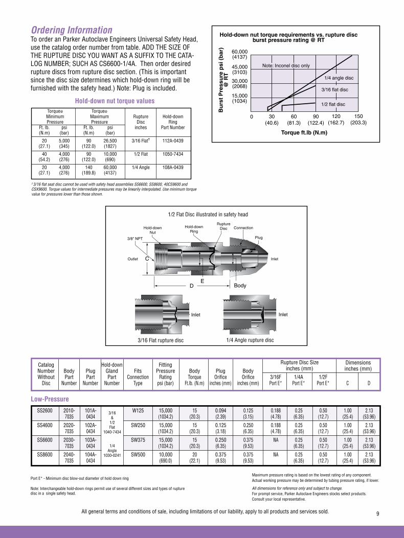
Port E* - Minimum disc blow-out diameter of hold down ring
Note: Interchangeable hold-down rings permit use of several different sizes and types of rupture disc in a single safety head.
Catalog Hold-down Fitting Number Body Plug Gland Fits Pressure Body Plug Body Without Part Part Part Connection Rating Torque Orifice Orifice 3/16F 1/4A 1/2F Disc Number Number Number Type psi (bar) Ft.lb. (N.m) inches (mm) inches (mm) Port E* Port E* Port E* C D
Rupture Disc Sizeinches (mm)
Low-Pressure
Ordering InformationTo order an Parker Autoclave Engineers Universal Safety Head, use the catalog order number from table. ADD THE SIZE OF THE RUPTURE DISC YOU WANT AS A SUFFIX TO THE CATA-LOG NUMBER; SUCH AS CS6600-1/4A. Then order desired rupture discs from rupture disc section. (This is important since the disc size determines which hold-down ring will be furnished with the safety head.) Note: Plug is included.
Dimensionsinches (mm)
SS2600 2010- 101A- W125 15,000 15 0.094 0.125 0.188 0.25 0.50 1.00 2.13 7035 0434 (1034.2) (20.3) (2.39) (3.15) (4.78) (6.35) (12.7) (25.4) (53.96)
SS4600 2020- 102A- SW250 15,000 15 0.125 0.250 0.188 0.25 0.50 1.00 2.13 7035 0434 (1034.2) (20.3) (3.18) (6.35) (4.78) (6.35) (12.7) (25.4) (53.96)
SS6600 2030- 103A- SW375 15,000 15 0.250 0.375 NA 0.25 0.50 1.00 2.13 7035 0434 (1034.2) (20.3) (6.35) (9.53) (6.35) (12.7) (25.4) (53.96)
SS8600 2040- 104A- SW500 10,000 20 0.375 0.375 NA 0.25 0.50 1.00 2.13 7035 0434 (690.0) (22.1) (9.53) (9.53) (6.35) (12.7) (25.4) (53.96)
Maximum pressure rating is based on the lowest rating of any component. Actual working pressure may be determined by tubing pressure rating, if lower.
All dimensions for reference only and subject to change.For prompt service, Parker Autoclave Engineers stocks select products. Consult your local representative.
3/16 &
1/2Flat
1040-7434
1/4 Angle
1030-0241
3/16 Flat rupture disc 1/4 Angle rupture disc
1/2 Flat Disc illustrated in safety head
150(203.3)
120(162.7)
90(122.4)
60(81.3)
30(40.6)
15,000(1034)
Bu
rst
Pre
ssu
re p
si (
bar
)@
RT
Torque ft.lb (N.m)
0
30,000(2068)
45,000(3103)
60,000(4137)
Hold-down nut torque requirements vs. rupture disc burst pressure rating @ RT
Note: Inconel disc only
1/4 angle disc
3/16 flat disc
1/2 flat discHold-down nut torque values Torque@ Torque@
Minimum Maximum Rupture Hold-down Pressure Pressure Disc Ring Ft. lb. psi Ft. lb. psi inches Part Number (N.m) (bar) (N.m) (bar)
20 5,000 90 26,500 3/16 Flat= 112A-0439 (27.1) (345) (122.0) (1827)
40 4,000 90 10,000 1/2 Flat 1050-7434 (54.2) (276) (122.0) (690)
20 4,000 140 60,000 1/4 Angle 108A-0439 (27.1) (276) (189.8) (4137)
All general terms and conditions of sale, including limitations of our liability, apply to all products and services sold. 9
† 3/16 flat seat disc cannot be used with safety head assemblies SS6600, SS8600, 40CS9600 andCSX9600. Torque values for intermediate pressures may be linearily interpolated. Use minimum torquevalue for pressures lower than those shown.
Inlet
C
D Body
Plug
ConnectionRupture
DiscHold-downRing
Hold-downNut
E
3/8" NPT
InletOutlet
Inlet
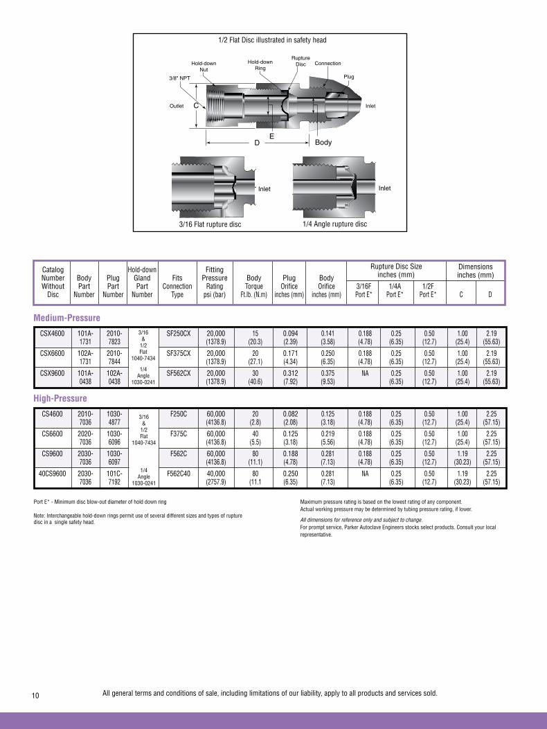
Catalog Hold-down Fitting Number Body Plug Gland Fits Pressure Body Plug Body Without Part Part Part Connection Rating Torque Orifice Orifice 3/16F 1/4A 1/2F Disc Number Number Number Type psi (bar) Ft.lb. (N.m) inches (mm) inches (mm) Port E* Port E* Port E* C D
Rupture Disc Sizeinches (mm)
Dimensionsinches (mm)
Medium-Pressure
CSX4600 101A- 2010- SF250CX 20,000 15 0.094 0.141 0.188 0.25 0.50 1.00 2.19 1731 7823 (1378.9) (20.3) (2.39) (3.58) (4.78) (6.35) (12.7) (25.4) (55.63)
CSX6600 102A- 2010- SF375CX 20,000 20 0.171 0.250 0.188 0.25 0.50 1.00 2.19 1731 7844 (1378.9) (27.1) (4.34) (6.35) (4.78) (6.35) (12.7) (25.4) (55.63)
CSX9600 101A- 102A- SF562CX 20,000 30 0.312 0.375 NA 0.25 0.50 1.00 2.19 0438 0438 (1378.9) (40.6) (7.92) (9.53) (6.35) (12.7) (25.4) (55.63)
High-Pressure
CS4600 2010- 1030- F250C 60,000 20 0.082 0.125 0.188 0.25 0.50 1.00 2.25 7036 4877 (4136.8) (2.8) (2.08) (3.18) (4.78) (6.35) (12.7) (25.4) (57.15)
CS6600 2020- 1030- F375C 60,000 40 0.125 0.219 0.188 0.25 0.50 1.00 2.25 7036 6096 (4136.8) (5.5) (3.18) (5.56) (4.78) (6.35) (12.7) (25.4) (57.15)
CS9600 2030- 1030- F562C 60,000 80 0.188 0.281 0.188 0.25 0.50 1.19 2.25 7036 6097 (4136.8) (11.1) (4.78) (7.13) (4.78) (6.35) (12.7) (30.23) (57.15)
40CS9600 2030- 101C- F562C40 40,000 80 0.250 0.281 NA 0.25 0.50 1.19 2.25 7036 7192 (2757.9) (11.1 (6.35) (7.13) (6.35) (12.7) (30.23) (57.15)
3/16 &
1/2Flat
1040-7434
1/4 Angle
1030-0241
3/16 &
1/2Flat
1040-7434
1/4 Angle
1030-0241
3/16 Flat rupture disc 1/4 Angle rupture disc
1/2 Flat Disc illustrated in safety head
Port E* - Minimum disc blow-out diameter of hold down ring
Note: Interchangeable hold-down rings permit use of several different sizes and types of rupture disc in a single safety head.
Maximum pressure rating is based on the lowest rating of any component. Actual working pressure may be determined by tubing pressure rating, if lower.
All dimensions for reference only and subject to change.For prompt service, Parker Autoclave Engineers stocks select products. Consult your local representative.
All general terms and conditions of sale, including limitations of our liability, apply to all products and services sold.10
C
D Body
Plug
ConnectionRupture
DiscHold-downRing
Hold-downNut
E
3/8" NPT
InletOutlet
InletInlet

• Specify quantity, disc size, type, material and temperature.• Indicate desired rupture rating which should be at least
110% of operating pressure. The burst rating tolerance is +/- 5% of the furnished tag rating. Discs are rated at 72°F (22°C).• 0% optional manufacturing range is available upon request.
0% option provides the burst pressure requested with a +/-5% burst tolerance. • Minimum order of 6 discs required for materials other than
Inconel.• See next page for standard part numbers.
Note: Inconel disc normally available from stock.
PTFE coating available on one or both sides to increase minimum rupture rating.
CAUTION: High pressure-to-rupture ratios, severe pressure or temperature cycling, corrosion and metal fatigue affect disc life and rupture pressure. Frequent disc replacement may be desirable to avoid premature rupture. Rupture disc manufacturers recommended a 140 to 170 percent margin on disc ratings for extended disc life.
All dimensions for reference only and subject to change.For prompt service, Parker Autoclave Engineers stocks select products. Consult your local representative.
Accessories - Prebulged Rupture DiscsOrdering Information
Disc Disc Size Rupture Pressures Standard Maximum Temperature Material Seat Type Available Range ± 5% Rating
Inches psi (bar) °F (°C)
3/16 flat 220 to 1,750 (15.2 to 120.7) 250 (121)
Aluminum 1/4 angle 160 to 2,000 (11.0 to 137.9) 250 (121)
1/2 flat 90 to 1,000 (6.2 to 68.9) 250 (121)
3/16 flat 500 to 4,500 (34.5 to 310.3) 250 (121)
Silver 1/4 angle 360 to 6,000 (24.8 to 413.7) 250 (121)
1/2 flat 190 to 1,700 (13.1 to 117.2) 250 (121)
3/16 flat 4,400 to 65,000 (303.4 to 4481.5) 1,000 (538)
Hastelloy C 1/4 angle 3,300 to 70,000 (227.5 to 4826.3) 1,000 (538)
1/2 flat 1,000 to 11,500 (68.9 to 792.9) 1,000 (538)
3/16 flat 770 to 20,000 (53.1 to 1378.9) 750 (399)
Nickel 1/4 angle 550 to 35,000 (37.9 to 2413.1) 750 (399)
1/2 flat 300 to 7,500 (20.7 to 517.1) 750 (399)
3/16 flat 2,650 to 20,000 (182.7 to 1378.9) 800 (427)
Monel 1/4 angle 2,000 to 40,000 (137.9 to 2757.9) 800 (427)
1/2 flat 1,000 to 7,500 (68.5 to 517.1) 800 (427)
3/16 flat 1,250 to 20,000 (86.2 to 1378.9) 900 (482)
Inconel 600 (Standard) 1/4 angle 900 to 75,000 (62.1 to 5171.0) 900 (482)
1/2 flat 500 to 10,000 (34.5 to 690.0) 900 (482)
3/16 flat 1,750 to 20,000 (120.7 to 1378.9) 900 (482)
Type 316 Stainless Steel 1/4 angle 1,250 to 60,000 (86.2 to 4136.8) 900 (482)
1/2 flat 700 to 10,000 (48.3 to 690.0) 900 (482)
1/4A Ref. O.D..62" (15.7 mm)
1/4" Dia.(6.35 mm)
Flat Seat Rupture Disc 30° Angular Seat Rupture Disc
All general terms and conditions of sale, including limitations of our liability, apply to all products and services sold. 11
3/16 F Ref. O.D..375" (9.53 mm)
1/2 F Ref. O.D..68" (17.3 mm)
3/16" Dia.(4.76 mm)
1/2" Dia.(12.7 mm)

Rupture Disc Stock Part List - 3/16 Flat Disc
Part Pressure Pressure Number Description Material Range Range (psi) (bar)
P-7003 3/16F DISC Inconel 1940-2120 134-146P-7674 3/16F DISC Inconel 2231-2438 154-168 P-7005 3/16F DISC Inconel 2910-3180 201-219P-7007 3/16F DISC Inconel 3201-3498 221-241P-7009 3/16F DISC Inconel 3880-4240 268-292P-7011 3/16F DISC Inconel 4365-4700 301-324P-7013 3/16F DISC Inconel 4850-5300 334-365P-7015 3/16F DISC Inconel 5141-5618 355-387P-7017 3/16F DISC Inconel 5335-5830 368-402P-7018 3/16F DISC Inconel 5626-6148 388-424P-7019 3/16F DISC Inconel 5723-6254 395-431P-7020 3/16F DISC Inconel 5820-6360 401-439P-7021 3/16F DISC Inconel 6014-6572 415-453P-7022 3/16F DISC Inconel 6111-6678 421-460P-7024 3/16F DISC Inconel 6305-6890 435-475P-7026 3/16F DISC Inconel 6790-7420 468-512P-7028 3/16F DISC Inconel 7275-7950 502-548P-7030 3/16F DISC Inconel 7760-8480 535-585P-7032 3/16F DISC Inconel 8245-9010 568-621P-7034 3/16F DISC Inconel 8730-9540 602-658P-7040 3/16F DISC Inconel 10185-11130 702-767P-7044 3/16F DISC Inconel 11155-12190 769-840P-7046 3/16F DISC Inconel 11640-12720 803-877P-7048 3/16F DISC Inconel 12125-13250 836-914P-7050 3/16F DISC Inconel 12610-13780 869-950P-7052 3/16F DISC Inconel 13095-14310 903-987P-7054 3/16F DISC Inconel 13580-14840 936-1023P-7056 3/16F DISC Inconel 14065-15370 970-1060P-7058 3/16F DISC Inconel 14550-15900 1003-1096P-7060 3/16F DISC Inconel 15035-16430 1037-1133P-7062 3/16F DISC Inconel 15520-16960 1070-1169P-7064 3/16F DISC Inconel 16005-17490 1103-1206P-7068 3/16F DISC Inconel 16975-18550 1170-1279P-7072 3/16F DISC Inconel 17945-19610 1237-1352P-7074 3/16F DISC Inconel 18430-20140 1271-1389P-7080 3/16F DISC Inconel 19885-21730 1371-1498P-7082 3/16F DISC Inconel 20370-22260 1404-1535P-7084 3/16F DISC Inconel 20885-22790 1440-1571P-7086 3/16F DISC Inconel 21340-23320 1471-1608P-7088 3/16F DISC Inconel 21825-23850 1505-1644P-7094 3/16F DISC Inconel 23280-25440 1605-1754P-7096 3/16F DISC Inconel 24250-26500 1672-1827 P-7098 3/16F DISC Inconel 24735-27030 1705-1864
All general terms and conditions of sale, including limitations of our liability, apply to all products and services sold.12

Rupture Disc Stock Part List - 1/4 Angle Disc
Part Pressure Pressure Number Description Material Range Range (psi) (bar)
P-7301 1/4A DISC Inconel 970-1060 67-73 P-7303 1/4A DISC Inconel 1164-1272 80-88 P-7305 1/4A DISC Inconel 1445-1590 100-110 P-7307 1/4A DISC Inconel 1697-1855 117-128 P-7309 1/4A DISC Inconel 1940-2120 134-146 P-7311 1/4A DISC Inconel 2425-2650 167-183 P-7313 1/4A DISC Inconel 2910-3180 201-219P-7315 1/4A DISC Inconel 3395-3710 234-256 P-7317 1/4A DISC Inconel 3880-4240 268-292 P-7319 1/4A DISC Inconel 4365-4770 301-329 P-7321 1/4A DISC Inconel 4850-5300 334-365 P-7323 1/4A DISC Inconel 5335-5830 368-402 P-7325 1/4A DISC Inconel 5820-6360 401-438 P-7327 1/4A DISC Inconel 6305-6890 435-475P-7329 1/4A DISC Inconel 6790-7420 468-512P-7331 1/4A DISC Inconel 7275-7950 502-548P-7333 1/4A DISC Inconel 7760-8480 535-585P-7335 1/4A DISC Inconel 8245-9010 568-621P-7337 1/4A DISC Inconel 8730-9540 602-658P-7339 1/4A DISC Inconel 9215-10070 635-694P-7341 1/4A DISC Inconel 9700-10600 669-731P-7343 1/4A DISC Inconel 10185-11130 702-767P-7345 1/4A DISC Inconel 10670-11660 736-804P-7347 1/4A DISC Inconel 11155-12190 769-841P-7349 1/4A DISC Inconel 11640-12720 803-877P-7351 1/4A DISC Inconel 12125-13250 836-914P-7353 1/4A DISC Inconel 12610-13780 869-950P-7355 1/4A DISC Inconel 13095-14310 903-987P-7357 1/4A DISC Inconel 13580-14840 936-1023P-7361 1/4A DISC Inconel 14550-15900 1003-1096P-7363 1/4A DISC Inconel 15035-16430 1037-1133P-7365 1/4A DISC Inconel 15520-16960 1070-1169P-7367 1/4A DISC Inconel 16005-17490 1103-1206P-7369 1/4A DISC Inconel 16490-18020 1137-1242P-7371 1/4A DISC Inconel 16975-18550 1170-1279P-7373 1/4A DISC Inconel 17460-19080 1204-1315P-7375 1/4A DISC Inconel 17945-19610 1237-1352P-7377 1/4A DISC Inconel 18915-20670 1304-1425P-7379 1/4A DISC Inconel 19400-21200 1338-1462P-7381 1/4A DISC Inconel 19885-21730 1371-1498P-7382 1/4A DISC Inconel 21000-22000 1448-1517P-7383 1/4A DISC Inconel 21825-23850 1505-1644P-7385 1/4A DISC Inconel 24250-26500 1672-1827
All general terms and conditions of sale, including limitations of our liability, apply to all products and services sold. 13

Part Pressure Pressure Number Description Material Range Range (psi) (bar)
P-7387 1/4A DISC Inconel 25220-27560 1739-1900P-7389 1/4A DISC Inconel 26190-28620 1806-1973P-7391 1/4A DISC Inconel 27160-29680 1873-2046P-7393 1/4A DISC Inconel 29100-31800 2006-2192P-7395 1/4A DISC Inconel 30070-32860 2073-2266P-7397 1/4A DISC Inconel 31525-34450 2174-2375P-7399 1/4A DISC Inconel 33950-37100 2341-2558P-7401 1/4A DISC Inconel 36375-39750 2508-2741P-7403 1/4A DISC Inconel 38880-42400 2681-2923P-7405 1/4A DISC Inconel 41255-45050 2844-3106P-7407 1/4A DISC Inconel 43650-47700 3010-3289P-7409 1/4A DISC Inconel 48500-53000 3344-3654P-7411 1/4A DISC Inconel 53350-58300 3678-4020P-7413 1/4A DISC Inconel 58200-63600 4013-4385P-7415 1/4A DISC Inconel 62155-66000 4285-4550P-7417 1/4A DISC Inconel 65960-72080 4548-4970P-7419 1/4A DISC Inconel 68870-75260 4748-5189
Rupture Disc Stock Part List - 1/4 Angle Disc - con’t
14 All general terms and conditions of sale, including limitations of our liability, apply to all products and services sold.

Part Pressure Pressure Number Description Material Range Range (psi) (bar)
P-7601 1/2F DISC Inconel 485-530 33-37P-7603 1/2F DISC Inconel 679-742 47-51P-7605 1/2F DISC Inconel 727-795 50-55P-7607 1/2F DISC Inconel 873-954 60-73P-7609 1/2F DISC Inconel 970-1060 67-75P-7610 1/2F DISC Inconel 1006-1100 69-76P-7611 1/2F DISC Inconel 1164-1272 80-88P-7613 1/2F DISC Inconel 1213-1323 84-91P-7615 1/2F DISC Inconel 1358-1484 94-102P-7617 1/2F DISC Inconel 1455-1590 100-110P-7619 1/2F DISC Inconel 1552-1696 107-117P-7621 1/2F DISC Inconel 1697-1855 117-128P-7623 1/2F DISC Inconel 1746-1908 120-132P-7625 1/2F DISC Inconel 1940-2120 134-146P-7627 1/2F DISC Inconel 2183-2385 151-164P-7629 1/2F DISC Inconel 2271-2438 157-168P-7631 1/2F DISC Inconel 2425-2650 167-183P-7633 1/2F DISC Inconel 2619-2862 181-197P-7635 1/2F DISC Inconel 2716-2968 187-204P-7637 1/2F DISC Inconel 2910-3180 201-219P-7639 1/2F DISC Inconel 3104-3392 214-234P-7641 1/2F DISC Inconel 3395-3710 234-256P-7643 1/2F DISC Inconel 3589-3922 247-270P-7645 1/2F DISC Inconel 3637-3975 251-274P-7647 1/2F DISC Inconel 3880-4240 268-292P-7649 1/2F DISC Inconel 4365-4770 301-329P-7651 1/2F DISC Inconel 4462-4876 308-336P-7653 1/2F DISC Inconel 4850-5300 334-365P-7655 1/2F DISC Inconel 5335-5830 368-402P-7657 1/2F DISC Inconel 5626-6148 388-424P-7659 1/2F DISC Inconel 5820-6360 401-438P-7661 1/2F DISC Inconel 6305-6890 435-475P-7663 1/2F DISC Inconel 6790-7420 468-512P-7665 1/2F DISC Inconel 7275-7950 502-548P-7667 1/2F DISC Inconel 7760-8480 535-585P-7669 1/2F DISC Inconel 8245-9010 568-621P-7671 1/2F DISC Inconel 8730-9540 602-658P-7673 1/2F DISC Inconel 9700-10600 669-731
Rupture Disc Stock Part List - 1/2 Flat Disc
All general terms and conditions of sale, including limitations of our liability, apply to all products and services sold. 15
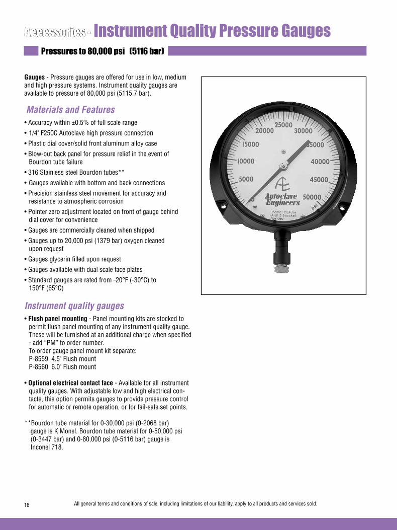
Accessories - Instrument Quality Pressure GaugesPressures to 80,000 psi (5116 bar)
Gauges - Pressure gauges are offered for use in low, medium and high pressure systems. Instrument quality gauges are available to pressure of 80,000 psi (5115.7 bar).
Materials and Features• Accuracy within ±0.5% of full scale range
• 1/4" F250C Autoclave high pressure connection
• Plastic dial cover/solid front aluminum alloy case
• Blow-out back panel for pressure relief in the event of Bourdon tube failure
• 316 Stainless steel Bourdon tubes**
• Gauges available with bottom and back connections
• Precision stainless steel movement for accuracy and resistance to atmospheric corrosion
• Pointer zero adjustment located on front of gauge behind dial cover for convenience
• Gauges are commercially cleaned when shipped
• Gauges up to 20,000 psi (1379 bar) oxygen cleaned upon request
• Gauges glycerin filled upon request
• Gauges available with dual scale face plates
• Standard gauges are rated from -20°F (-30°C) to 150°F (65°C)
Instrument quality gauges• Flush panel mounting - Panel mounting kits are stocked to
permit flush panel mounting of any instrument quality gauge. These will be furnished at an additional charge when specified - add “PM” to order number.
To order gauge panel mount kit separate: P-8559 4.5" Flush mount P-8560 6.0" Flush mount
• Optional electrical contact face - Available for all instrument quality gauges. With adjustable low and high electrical con-tacts, this option permits gauges to provide pressure control for automatic or remote operation, or for fail-safe set points.
**Bourdon tube material for 0-30,000 psi (0-2068 bar) gauge is K Monel. Bourdon tube material for 0-50,000 psi (0-3447 bar) and 0-80,000 psi (0-5116 bar) gauge is Inconel 718.
All general terms and conditions of sale, including limitations of our liability, apply to all products and services sold.16

Bottom connection calibrated in psi only
Pressure Minor Interval Dial Catalog Range Value Diameter Number psi (bar) psi (bar) inches (mm)
P-0499-CG 0-1,000 (0-69) 10 (.69) 4-1/2 (114.3)
P-0479-CG 0-1,500 (0-103) 10 (.69) 4-1/2 (114.3)
P-0480-CG 0-3,000 (0-207) 20 (1.38) 4-1/2 (114.3)
P-0481-CG 0-5,000 (0-345) 50 (3.44) 4-1/2 (114.3)
P-0482-CG 0-10,000 (0-690) 100 (6.89) 4-1/2 (114.3)
P-0483-CG 0-15,000 (0-1034) 100 (6.89) 4-1/2 (114.3)
P-0487-CG 0-20,000 (0-1379) 200 (13.79) 4-1/2 (114.3)
P-0488-CG** 0-30,000 (0-2068) 250 (17.24) 6 (152.4)
P-0489-CG** 0-50,000 (0-3447) 500 (34.47) 6 (152.4)
P-0490-CG** 0-80,000 (0-5116) 1,000 (68.94) 6 (152.4)
Gauge “A” “B” “C” Size cutout inches - (mm) inches - (mm) inches - (mm) inches - (mm)
4-1/2” (114.3) 4.937 (125.39) 5.375 (136.52) .218 (5.54)
6” (152.4) 6.437 (163.49) 7.0 (177.80) .218 (5.54)
**Bourdon tube material for 0-30,000 psi (0-2068 bar) gauge is K Monel. Bourdon tube material for 0-50,000 psi (0-3447 bar) and 0-80,000 psi (0-5116 bar) gauge is Inconel 718.
Note: Gauge connections are 1/4” (F250C) coned-and-threaded connection. Furnished with collar and gland.
"B" DIAMETER
120 TYPICAL
"C" DIAMETER Catalog Number Fits Gauge Dial Diameter inches - (mm)
Optional Electrical Contact Face
All general terms and conditions of sale, including limitations of our liability, apply to all products and services sold. 17
Back connection gauges calibrated in psi only Pressure Minor Interval Dial Catalog Range Value Diameter Number psi (bar) psi (bar) inches (mm)
P-0482B-CG 0-10,000 (0-690) 100 (6.89) 4-1/2 (114.3)
P-0483B-CG 0-15,000 (0-1034) 100 (6.89) 4-1/2(114.3)
P-0487B-CG 0-20,000 (0-1379) 200 (13.79) 4-1/2 (114.3)
P-0488B-CG 0-30,000 (0-2068) 250 (17.24) 6 (152.4)
P-0489B-CG 0-50,000 (0-3447) 500 (34.47) 6 (152.4)
P-0713 4-1/2 (114.3)
P-0714 6 (152.4)
A
ModelsP-0489-CGP-0490-CGOnly
5.8(147.2)
1.62(41.15)
BackConnection
1.625(41.28)
.585(14.86)
0.875(22.23)

H4 - 1/4" High Pressure - F250CH6 - 3/8" High Pressure - F375C
Accessories - Gauge/Instrument SnubbersPressures to 60,000 psi (4137 bar)
Parker Autoclave Engineers Pressure Snubbers provide protection to gauges and instrumentation from pressure surges, pulsation and shock. The unique snubber design provides superior instrument protection while not compromis-ing instrument accuracy or reaction time. This is accomplished by the use of existing technology from our excess flow check valve with additional design features.
When sudden flow is seen, the poppet will rise, blocking the pressure surge and a small bleed hole in the poppet will allow pressure to slowly equalize. When the pressure is equalized, the poppet will then drop back down allowing normal flow to the gauge. A filter is used to prevent the hole in the plug from becoming plugged. The snubber must be mounted in the vertical position as indicated on the unit.
Snubbers are offered in 316SS as standard, with either male, female or male/female connections in 1/4" and 3/8" sizes. Optional materials available upon request.
Typical catalog number: SNB F H4 F H4
H4Outlet
Connection
FFemale
H4Inlet
Connection
FFemale
SNBGauge
Snubber
INLET
Available End Connections
All general terms and conditions of sale, including limitations of our liability, apply to all products and services sold.18

A C
B
HEX
D HEX
A
C
B
HEX
A
B
HEX
CC
D HEX
D HEX
Catalog Pressure Dimensions – Inches (mm) Fig Number Rating psi (bar) A B C D Hex
Accessories - Gauge/Instrument Snubbers
Figure 1
Figure 2
Figure 3
A C
B
HEX
D HEX
A
C
B
HEX
A
B
HEX
CC
D HEX
D HEX
A C
B
HEX
D HEX
A
C
B
HEX
A
B
HEX
CC
D HEX
D HEX
All general terms and conditions of sale, including limitations of our liability, apply to all products and services sold. 19
SNBFH4FH4 60,000 (4137) 3.36 (85.34) 2.50 (63.50) 0.50 (12.70) 0.63 (15.33) 1.19 (30.15) 1
SNBFH4MH4 60,000 (4137) 4.05 (102.87) 2.50 (63.50) 0.50 (12.70) 0.63 (15.33) 1.19 (30.15) 2
SNBMH6MH4 60,000 (4137) 3.68 (93.47) 2.13 (54.10) 1.50 (38.10) 0.75 (19.05) 1.19 (30.15) 3

02-0134SE January2013© 2013 Parker Hannifin Corporation | Autoclave Engineers is a registered trademark of the Parker Hannifin Corporation
Parker Hannifin Manufacturing Ltd. Instrumentation Products Division, Europe Industrial Estate WhitemillWexford, Republic of IrelandPH: 353 53 914 1566FAX: 353 53 914 1582
Instrumentation Products DivisionAutoclave Engineers Operation8325 Hessinger DriveErie, Pennsylvania 16509-4679 USAPH: 814-860-5700 FAX: 814-860-5811www.autoclave.com
WARNING
FAILURE, IMPROPER SELECTION OR IMPROPER USE OF THE PRODUCTS AND/OR SYSTEMS DESCRIBED HEREIN OR RELATED ITEMS CAN CAUSE DEATH, PERSONAL INJURY AND PROPERTY DAMAGE.This document and other information from Parker Hannifin Corporation, its subsidiaries and authorized distributors provide product and/or system options for further investigation by users having technical expertise. It is important that you analyze all aspects of your application and review the information concerning the product or system in the current product catalog. Due to the variety of operating conditions and applications for these products or systems, the user, through its own analysis and testing, is solely responsible for making the final selection of the products and systems and assuring that all performance, safety and warning requirements of the application are met. The products described herein, including without limitation, product features, specifications, designs, availability and pricing, are subject to change by Parker Hannifin Corporation and its subsidiaries at any time without notice.
Offer of Sale
The items described in this document are available for sale by Parker Hannifin Corporation, its subsidiaries or its authorized distributors. Any sale contract entered by Parker will be governed by the provisions stated in Parker's standard terms and conditions of sale (copy available upon request).
ISO-9001 Certified
Caution! Do not mix or interchange parts or tubing with those of other manufacturers. Doing so is unsafe and will void warranty.
Caution! Parker Autoclave Engineers Valves, Fittings and Tools are not designed to work with common commercial instrument tubing and will only work with tubing built to Parker Autoclave Engineers AES Specifications. Failure to do so will void warranty.

All general terms and conditions of sale, including limitations of our liability, apply to all products and services sold. 1
For over 50 years Parker Autoclave Engineers has designed and built premium quality valves, fittings and tubing. This commitment to engineering and manufacturing excellence has earned Parker Autoclave a reputation for reliable, efficient product performance and has established Autoclave as the worldwide leader in high pressure fluid components for the oil and gas industry. Parker Autoclave Engineers designs and builds high pres-sure valves, fittings and tubing for use with sour oil and gas (H2S). Parker Autoclave Engineers “SOG” components meet or exceed all requirements of NACE MR0175-2002. High Pressure Valve Features:
• Rising stem/barstock body design.
• Metal-to-metal seating achieves bubble-tight shut-off, longer stem/seat life in abrasive flow, greater durabil-ity for repeated on/off cycles and excellent corrosion resistance.
• PTFE encapsulated packing provides dependable stem and body sealing.
• Solid, one-piece stem provides an economical valve for SOG service.
• Optional non-rotating stem assembly available.
• Stem and packing gland materials have been selected to optimize thread cycle life.
Parker Autoclave Engineers valves are complemented by a complete line of high pressure fittings, tubing and check valves. All high pressure valves and fittings use Parker Autclave Engineers' high pressure coned-and-threaded con-nections for dependable performance under widely varying conditions.
www.autoclaveengineers.com
Sour Service ProductsPressures to 30,000 psi (2068 bar)
Sour Service Products
www.autoclave.com
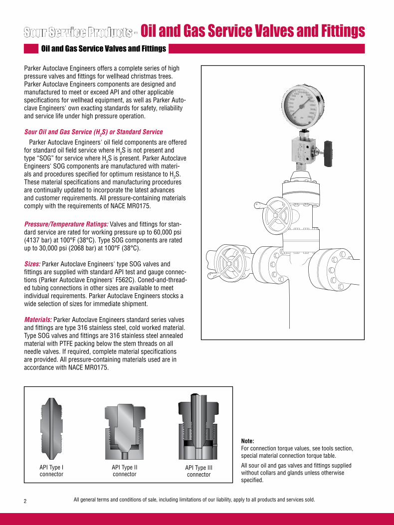
All general terms and conditions of sale, including limitations of our liability, apply to all products and services sold.2
Parker Autoclave Engineers offers a complete series of high pressure valves and fittings for wellhead christmas trees. Parker Autoclave Engineers components are designed and manufactured to meet or exceed API and other applicable specifications for wellhead equipment, as well as Parker Auto-clave Engineers' own exacting standards for safety, reliability and service life under high pressure operation.
Sour Oil and Gas Service (H2S) or Standard Service
Parker Autoclave Engineers' oil field components are offered for standard oil field service where H2S is not present and type “SOG” for service where H2S is present. Parker Autoclave Engineers' SOG components are manufactured with materi-als and procedures specified for optimum resistance to H2S. These material specifications and manufacturing procedures are continually updated to incorporate the latest advances and customer requirements. All pressure-containing materials comply with the requirements of NACE MR0175.
Pressure/Temperature Ratings: Valves and fittings for stan-dard service are rated for working pressure up to 60,000 psi (4137 bar) at 100°F (38°C). Type SOG components are rated up to 30,000 psi (2068 bar) at 100°F (38°C).
Sizes: Parker Autoclave Engineers' type SOG valves and fittings are supplied with standard API test and gauge connec-tions (Parker Autoclave Engineers' F562C). Coned-and-thread-ed tubing connections in other sizes are available to meet individual requirements. Parker Autoclave Engineers stocks a wide selection of sizes for immediate shipment.
Materials: Parker Autoclave Engineers standard series valves and fittings are type 316 stainless steel, cold worked material. Type SOG valves and fittings are 316 stainless steel annealed material with PTFE packing below the stem threads on all needle valves. If required, complete material specifications are provided. All pressure-containing materials used are in accordance with NACE MR0175.
Sour Service Products - Oil and Gas Service Valves and FittingsOil and Gas Service Valves and Fittings
All sour oil and gas valves and fittings supplied without collars and glands unless otherwise specified.
API Type Iconnector
API Type IIconnector
API Type IIIconnector
Note:For connection torque values, see tools section, special material connection torque table.
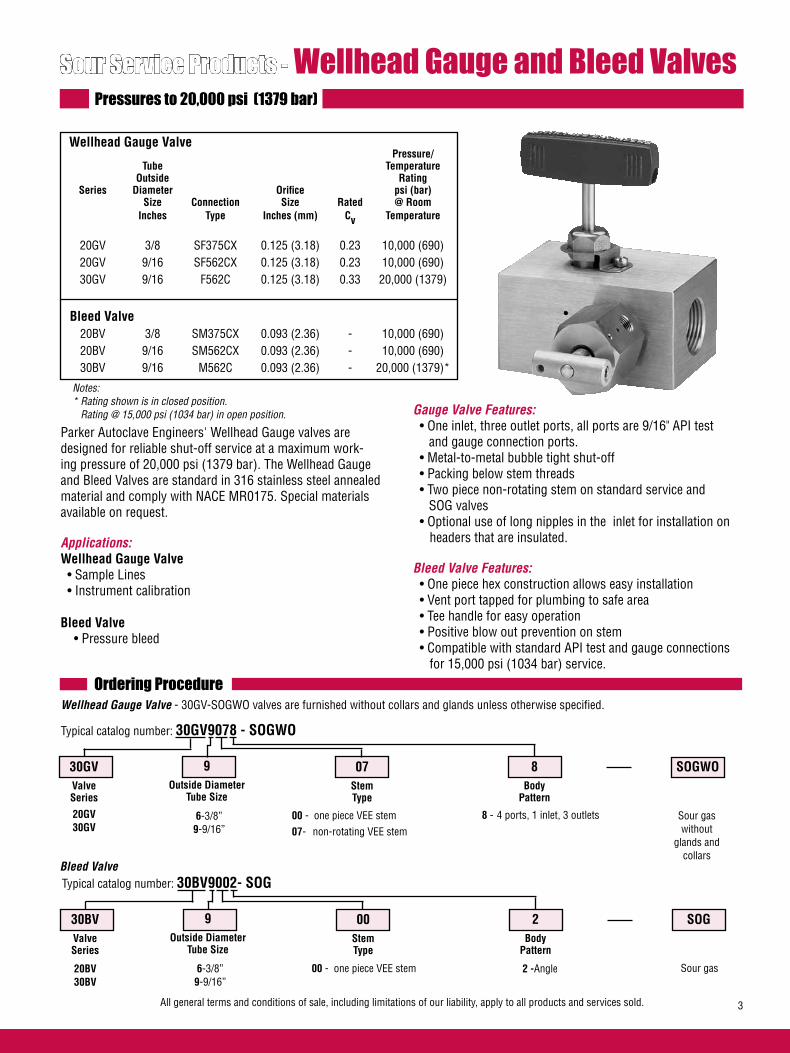
All general terms and conditions of sale, including limitations of our liability, apply to all products and services sold. 3
Pressure/ Tube Temperature Outside Rating Series Diameter Orifice psi (bar) Size Connection Size Rated @ Room Inches Type Inches (mm) Cv Temperature 20GV 3/8 SF375CX 0.125 (3.18) 0.23 10,000 (690) 20GV 9/16 SF562CX 0.125 (3.18) 0.23 10,000 (690) 30GV 9/16 F562C 0.125 (3.18) 0.33 20,000 (1379)
Bleed Valve 20BV 3/8 SM375CX 0.093 (2.36) - 10,000 (690) 20BV 9/16 SM562CX 0.093 (2.36) - 10,000 (690) 30BV 9/16 M562C 0.093 (2.36) - 20,000 (1379)*
Ordering ProcedureWellhead Gauge Valve - 30GV-SOGWO valves are furnished without collars and glands unless otherwise specified.
6-3/8”9-9/16”
00 - one piece VEE stem07- non-rotating VEE stem
8 - 4 ports, 1 inlet, 3 outlets
SOGWO8Body
Pattern
07StemType
9Outside Diameter
Tube Size
30GVValveSeries
Sour Service Products - Wellhead Gauge and Bleed ValvesPressures to 20,000 psi (1379 bar)
Notes: * Rating shown is in closed position. Rating @ 15,000 psi (1034 bar) in open position.
Parker Autoclave Engineers' Wellhead Gauge valves are designed for reliable shut-off service at a maximum work-ing pressure of 20,000 psi (1379 bar). The Wellhead Gauge and Bleed Valves are standard in 316 stainless steel annealed material and comply with NACE MR0175. Special materials available on request.
Applications: Wellhead Gauge Valve • Sample Lines • Instrument calibration
Bleed Valve • Pressure bleed
Gauge Valve Features: • One inlet, three outlet ports, all ports are 9/16" API test and gauge connection ports. • Metal-to-metal bubble tight shut-off • Packing below stem threads • Two piece non-rotating stem on standard service and SOG valves • Optional use of long nipples in the inlet for installation on headers that are insulated. Bleed Valve Features: • One piece hex construction allows easy installation • Vent port tapped for plumbing to safe area • Tee handle for easy operation • Positive blow out prevention on stem • Compatible with standard API test and gauge connections for 15,000 psi (1034 bar) service.
20GV30GV
Typical catalog number: 30GV9078 - SOGWO
6-3/8”9-9/16”
00 - one piece VEE stem 2 -Angle
SOG2Body
Pattern
00StemType
9Outside Diameter
Tube Size
30BVValveSeries
20BV30BV
Typical catalog number: 30BV9002- SOGBleed Valve
Sour gas without
glands and collars
Sour gas
Wellhead Gauge Valve
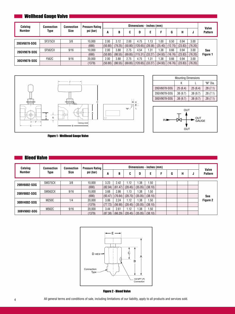
All general terms and conditions of sale, including limitations of our liability, apply to all products and services sold.4
Valve A B C D E F G H J Pattern
Dimensions - inches (mm)
SF375CX 3/8 10,000 2.00 3.12 2.00 4.75 1.13 1.00 0.50 0.94 3.00 (690) (50.80) (79.25) (50.80) (120.65) (28.58) (25.40) (12.70) (23.83) (76.20) SF562CX 9/16 10,000 2.00 3.88 2.75 4.54 1.31 1.38 0.66 0.94 3.00 (690) (50.80) (98.55) (69.85) (115.31) (33.27) (34.93) (16.76) (23.83) (76.20) F562C 9/16 20,000 2.00 3.88 2.75 4.75 1.31 1.38 0.66 0.94 3.00 (1379) (50.80) (98.55) (69.85) (120.65) (33.27) (34.93) (16.76) (23.83) (76.20)
Catalog Number
Connection Size
Pressure Ratingpsi (bar)
ConnectionType
See Figure 1
20GV6078-SOG
20GV9078-SOG
Wellhead Gauge Valve
Valve A B C D E F G H J Pattern
Dimensions - inches (mm)
SM375CX 3/8 10,000 3.23 2.42 1.12 1.38 1.50 (690) (82.04) (61.47) (28.45) (35.05) (38.10) SM562CX 9/16 10,000 3.68 2.86 1.13 1.38 1.50 (690) (93.47) (76.64) (28.70) (35.05) (38.10) M250C 1/4 20,000 3.06 2.24 1.12 1.38 1.50 (1379) (77.72) (56.90) (28.45) (35.05) (38.10) M562C 9/16 20,000 3.44 2.61 1.12 1.38 1.50 (1379) (87.38) (66.29) (28.45) (35.05) (38.10)
Catalog Number
Connection Size
Pressure Ratingpsi (bar)
ConnectionType
Figure 2 - Bleed Valve
See Figure 2
20BV6002-SOG
20BV9002-SOG
Bleed Valve
30BV4002-SOG
30GV9078-SOG
30BV9002-SOG
Figure 1 - Wellhead Gauge Valve
Mounting Dimensions
K L “M” Dia.
20GV6078-SOG .25 (6.4) .25 (6.4) .28 (7.1)
20GV9078-SOG .38 (9.7) .38 (9.7) .28 (7.1)
30GV9078-SOG .38 (9.7) .38 (9.7) .28 (7.1)
C
F
HG
BE
A
D
J
K
L"M"
C
B
A
E
D HEX
ConnectionType
1/8 NPT (F)Connection
OUTGAUGEIN
OUT
OUT
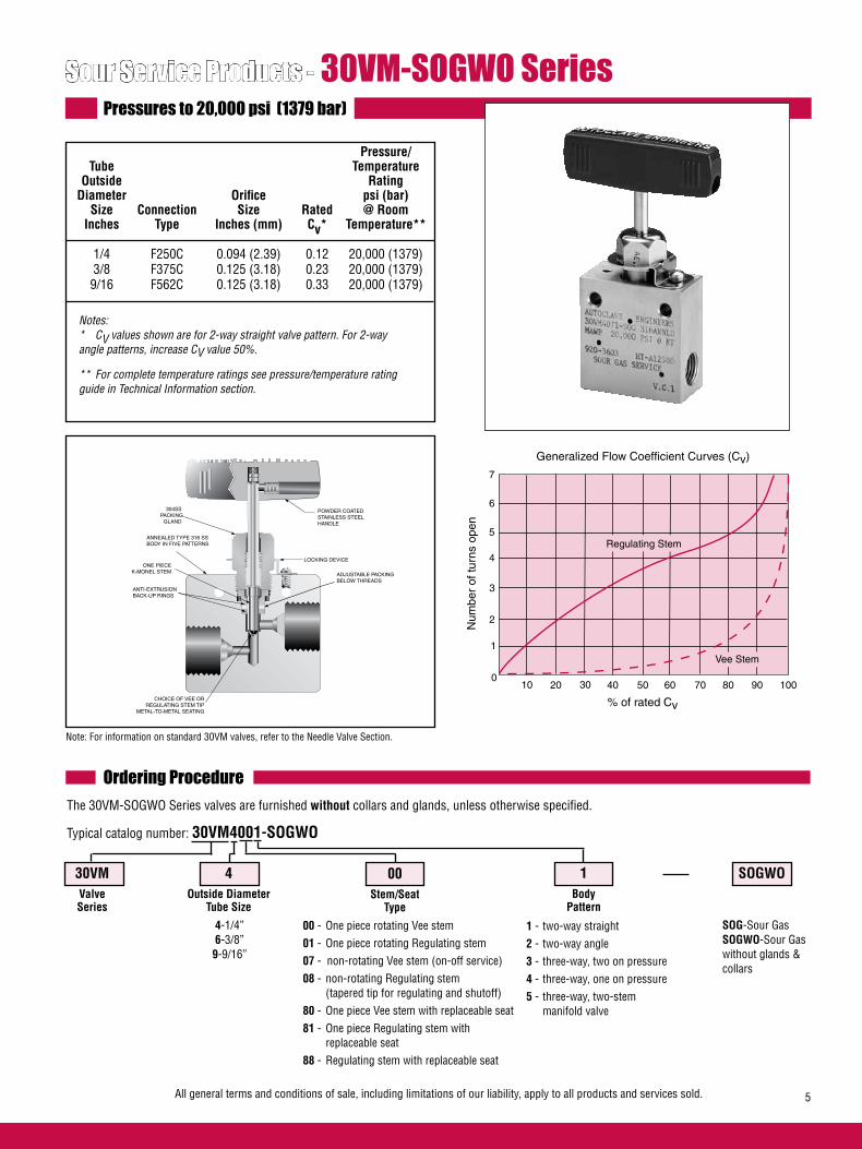
All general terms and conditions of sale, including limitations of our liability, apply to all products and services sold. 5
Sour Service Products - 30VM-SOGWO SeriesPressures to 20,000 psi (1379 bar)
Pressure/ Tube Temperature Outside Rating Diameter Orifice psi (bar) Size Connection Size Rated @ Room Inches Type Inches (mm) Cv* Temperature** 1/4 F250C 0.094 (2.39) 0.12 20,000 (1379) 3/8 F375C 0.125 (3.18) 0.23 20,000 (1379) 9/16 F562C 0.125 (3.18) 0.33 20,000 (1379)
Notes: * CV values shown are for 2-way straight valve pattern. For 2-way angle patterns, increase CV value 50%.
** For complete temperature ratings see pressure/temperature rating guide in Technical Information section.
Note: For information on standard 30VM valves, refer to the Needle Valve Section.
Ordering ProcedureThe 30VM-SOGWO Series valves are furnished without collars and glands, unless otherwise specified.
Typical catalog number: 30VM4001-SOGWO
4-1/4”6-3/8”9-9/16”
00 - One piece rotating Vee stem01 - One piece rotating Regulating stem07 - non-rotating Vee stem (on-off service)08 - non-rotating Regulating stem (tapered tip for regulating and shutoff)80 - One piece Vee stem with replaceable seat81 - One piece Regulating stem with replaceable seat88 - Regulating stem with replaceable seat
1 - two-way straight2 - two-way angle3 - three-way, two on pressure4 - three-way, one on pressure5 - three-way, two-stem manifold valve
SOGWO1Body
Pattern
00Stem/Seat
Type
4Outside Diameter
Tube Size
30VMValveSeries
SOG-Sour Gas SOGWO-Sour Gas without glands & collars
% of rated Cv
100
1
Num
ber
of tu
rns
open
Generalized Flow Coefficient Curves (Cv)
2
3
4
5
6
7
20 30 40 50 60 70 80 90 100
Regulating Stem
Vee Stem
POWDER COATEDSTAINLESS STEELHANDLE
304SS PACKING GLAND
ANNEALED TYPE 316 SS BODY IN FIVE PATTERNS
ONE PIECEK-MONEL STEM ADJUSTABLE PACKING
BELOW THREADS
LOCKING DEVICE
CHOICE OF VEE OR REGULATING STEM TIP
METAL-TO-METAL SEATING
ANTI-EXTRUSIONBACK-UP RINGS

All general terms and conditions of sale, including limitations of our liability, apply to all products and services sold.6
Valve Maintenance
Note: All sour service valves and fittings supplied without collars and glands unless otherwise specified.
Repair Kits: add “R” to the front of valve catalog number for proper repair kit. (Example: R30VM4001-SOGWO)Valve Bodies: Valve bodies are available. Order using the eight (8) digit part number found in the valve drawing or contact your Sales Representative for information.Consult your Parker Autoclave Engineers representative for pricing on repair kits and valve bodies. Refer to the Tools, Installation, Operation and Maintenance section for proper maintenance procedures.
2-Way Straight 30VM4001-SOGWO VEE 30VM4081-SOGWO REG 30VM6001-SOGWO VEE 30VM6081-SOGWO REG 30VM9001-SOGWO VEE 30VM9081-SOGWO REG
1/4 0.094 2.00 1.00 0.50 1.50 1.12 2.00 3.00 1.00 0.22 4.62 0.69 0.38 1.00 (6.35) (2.39) (50.80) (25.40) (12.70) (38.10) (28.45) (50.80) (76.20) (25.40) (5.59) (117.35) (17.53) (9.65) (25.40) 3/8 0.125 2.00 1.00 0.53 1.50 1.12 2.00 3.00 1.00 0.22 4.68 0.69 0.38 1.00 (9.53) (3.18) (50.80) (25.40) (13.46) (38.10) (28.45) (50.80) (76.20) (25.40) (5.59) (118.87) (17.53) (9.65) (25.40) 9/16 0.125 2.62 1.31 0.81 1.56 1.12 2.44 3.00 1.00 0.28 5.06 0.69 0.38 1.50 (14.29) (3.18) (66.55) (33.27) (20.57) (39.62) (28.45) (61.98) (76.20) (25.40) (7.11) (128.52) (17.53) (9.65) (38.10)
2-Way Angle 1/4 0.094 2.00 1.00 0.50 1.12 2.00 3.00 1.00 0.22 4.62 0.69 0.38 1.00 (6.35) (2.39) (50.80) (25.40) (12.70) (28.45) (50.80) (76.20) (25.40) (5.59) (117.35) (17.53) (9.65) (25.40) 3/8 0.125 2.00 1.00 0.53 1.12 2.12 3.00 1.00 0.22 4.74 0.69 0.38 1.00 (9.53) (3.18) (50.80) (25.40) (13.46) (28.45) (53.85) (76.20) (25.40) (5.59) (120.40) (17.53) (9.65) (25.40) 9/16 0.125 2.62 1.31 0.81 1.12 2.44 3.00 1.00 0.28 5.06 0.69 0.38 1.50 (14.29) (3.18) (66.55) (33.27) (20.57) (28.45) (61.98) (76.20) (25.40) (7.11) (128.52) (17.53) (9.65) (38.10)
3-Way / 2 on Pressure 1/4 0.094 2.00 1.00 0.50 1.50 1.12 2.12 3.00 1.00 0.22 4.74 0.69 0.38 1.00 (6.35) (2.39) (50.80) (25.40) (12.70) (38.10) (28.45) (53.85) (76.20) (25.40) (5.59) (120.40) (17.53) (9.65) (25.40) 3/8 0.125 2.00 1.00 0.53 1.50 1.12 2.50 3.00 1.00 0.22 5.12 0.69 0.38 1.00 (9.53) (3.18) (50.80) (25.40) (13.46) (38.10) (28.45) (63.50) (76.20) (25.40) (5.59) (130.05) (17.53) (9.65) (25.40) 9/16 0.125 2.62 1.31 0.81 1.56 1.12 2.88 3.00 1.00 0.28 5.49 0.69 0.38 1.50 (14.29) (3.18) (66.55) (33.27) (20.57) (39.62) (28.45) (73.15) (76.20) (25.40) (7.11) (139.45) (17.53) (9.65) (38.10)
See Figure 1
See Figure 2
See Figure 3
2-Way Angle 3-Way / 2 on Pressure2-Way Straight
Figure 3Figure 2Figure 1
30VM4002-SOGWO VEE 30VM4082-SOGWO REG 30VM6002-SOGWO VEE 30VM6082-SOGWO REG 30VM9002-SOGWO VEE 30VM9082-SOGWO REG
30VM4003-SOGWO VEE 30VM4083-SOGWO REG 30VM6003-SOGWO VEE 30VM6083-SOGWO REG 30VM9003-SOGWO VEE 30VM9083-SOGWO REG
Block Thick- Valve A B C D D1 E F G G1 H* M N ness Pattern
Dimensions - inches (mm) Catalog
NumberOutside
DiameterTube
OrificeDiameter
StemType
H N
F
G1
G
D1DE
M M
AB
C
H N
F
G1
G
DE
M M
AB
C
H N
F
G1
G
D1
E
M M
AB
C
D
G - Packing gland mounting hole drill size All dimensions for reference only and subject to change. For prompt service, G1 - Bracket mounting hole size * H Dimension is with stem in the closed position. Parker Autoclave Engineers stocks Panel mounting drill size: 0.22” all valves. select products. Consult factory.

All general terms and conditions of sale, including limitations of our liability, apply to all products and services sold. 7
3-Way / 1 on Pressure 30VM4004-SOGWO VEE 30VM4084-SOGWO REG 30VM6004-SOGWO VEE 30VM6084-SOGWO REG 30VM9004-SOGWO VEE 30VM9084-SOGWO REG
1/4 0.094 2.00 1.00 0.50 1.12 2.00 3.00 1.00 0.22 4.62 0.69 0.38 1.00 (6.35) (2.39) (50.80) (25.40) (12.70) (28.45) (50.80) (76.20) (25.40) (5.59) (117.35) (17.53) (9.65) (25.40) 3/8 0.125 2.00 1.00 0.53 1.12 2.12 3.00 1.00 0.22 4.74 0.69 0.38 1.00 (9.53) (3.18) (50.80) (25.40) (13.46) (28.45) (53.85) (76.20) (25.40) (5.59) (120.40) (17.53) (9.65) (25.40) 9/16 0.125 2.62 1.31 0.81 1.12 2.44 3.00 1.00 0.28 5.12 0.69 0.38 1.50 (14.29) (3.18) (66.55) (33.27) (20.57) (28.45) (61.98) (76.20) (25.40) (7.11) (130.05) (17.53) (9.65) (38.10)
2-Way Angle / Replaceable Seat
3-Way / 2-Stem Manifold 1/4 0.094 2.00 1.00 0.50 1.53 1.12 3.06 3.00 1.00 0.22 5.68 0.69 0.38 1.00 (6.35) (2.39) (50.80) (25.40) (12.70) (38.86) (28.45) (77.72) (76.20) (25.40) (5.59) (144.27) (17.53) (9.65) (25.40) 3/8 0.125 2.00 1.00 0.53 1.62 1.12 3.25 3.00 1.00 0.22 5.87 0.69 0.38 1.00 (9.53) (3.18) (50.80) (25.40) (13.46) (41.15) (28.45) (82.55) (76.20) (25.40) (5.59) (149.10) (17.53) (9.65) (25.40) 9/16 0.125 2.62 1.31 0.81 1.88 1.12 3.75 3.00 1.00 0.28 6.37 0.69 0.38 1.50 (14.29) (3.18) (66.55) (33.27) (20.57) (47.75) (28.45) (95.25) (76.20) (25.40) (7.11) (161.80) (17.53) (9.65) (38.10)
See Figure 4
See Figure 5
See Figure 6
2-Way Angle / Replacable Seat 3-Way / 2-Stem Manifold3-Way / 1 on Pressure
Figure 6Figure 5Figure 4
G - Packing gland mounting hole drill size All dimensions for reference only and subject to change. For prompt service, G1 - Bracket mounting hole size * H Dimension is with stem in the closed position. Parker Autoclave Engineers stocks Panel mounting drill size: 0.22” all valves. select products. Consult factory.
Block Thick- Valve A B C D D1 E F G G1 H* M N ness Pattern
Dimensions - inches (mm) Catalog
NumberOutside
DiameterTube
OrificeDiameter
StemType
30VM4802-SOGWO VEE 30VM4882-SOGWO REG 30VM6802-SOGWO VEE 30VM6882-SOGWO REG 30VM9802-SOGWO VEE 30VM9882-SOGWO REG
30VM4005-SOGWO VEE 30VM4085-SOGWO REG 30VM6005-SOGWO VEE 30VM6085-SOGWO REG 30VM9005-SOGWO VEE 30VM9085-SOGWO REG
H N
F
G1
G
D
E
M M
AB
C
DH
N
F
G1
G
D
E
M M
A B
C
D1
H N
M M
F
G1
G
D1
E
CBA
D1
D
1/4 0.094 2.00 1.00 0.50 1.12 2.06 2.38 3.00 1.00 0.22 5.80 0.69 0.38 1.00 (6.35) (2.39) (50.80) (25.40) (12.70) (28.45) (52.32) (60.45) (76.20) (25.40) (5.59) (147.32) (17.53) (9.65) (25.40) 3/8 0.125 2.00 1.00 0.53 1.12 2.31 2.38 3.00 1.00 0.22 6.05 0.69 0.38 1.00 (9.53) (3.18) (50.80) (25.40) (13.46) (28.45) (58.67) (60.45) (76.20) (25.40) (5.59) (153.67) (17.53) (9.65) (25.40) 9/16 0.125 2.62 1.31 0.81 1.19 2.62 2.44 3.00 1.00 0.28 6.45 0.69 0.38 1.50 (14.29) (3.18) (66.55) (33.27) (20.57) (30.23) (66.55) (61.98) (76.20) (25.40) (7.11) (163.83) (17.53) (9.65) (38.10)

All general terms and conditions of sale, including limitations of our liability, apply to all products and services sold.8
Sour Service Products - 60VM-SOGWO SeriesPressures to 30,000 psi (2068 bar)
Pressure/ Tube Temperature Outside Rating Diameter Orifice psi (bar) Size Connection Size Rated @ Room Inches Type Inches (mm) Cv* Temperature** 1/4 F250C 0.062 (1.57) 0.08 30,000 (2068) 3/8 F375C 0.062 (1.57) 0.09 30,000 (2068) 9/16 F562C 0.078 (1.98) 0.14 30,000 (2068)
Notes: * CV values shown are for 2-way straight valve pattern. For 2-way angle patterns, increase CV value 50%.
** For complete temperature ratings see pressure/temperature rating guide in Technical Information section.
Note: For information in standard 60VM valves refer to the Needle Valve Section.
Ordering Procedure The 60VM-SOGWO Series valves are furnished without glands and collars, unless otherwise specified.
Typical catalog number: 60VM4071-SOGWO
4-1/4”6-3/8”9-9/16”
07 - non-rotating Vee stem (on-off service)08 - non-rotating regulating stem (tapered tip for regulating and shutoff)81 - Regulating one piece stem with replaceable seat87 - Vee stem with replaceable seat88 - Regulating stem with replaceable seat
1 - two-way straight2 - two-way angle3 - three-way, two on pressure4 - three-way, one on pressure5 - three-way, two-stem manifold valve
SOGWO1Body
Pattern
07Stem/Seat
Type
4Outside Diameter
Tube Size
60VMValveSeries
304SS PACKING GLAND
ANNEALED TYPE 316 SS BODY IN FIVE PATTERNS
ONE-PIECEK-MONEL
STEM
ADJUSTABLE PACKINGBELOW THREADS
LOCKING DEVICE
HIGH PRESSURE CONED-AND-THREADED CONNECTIONS
CHOICE OF VEE OR REGULATING STEM TIP
METAL-TO-METAL SEATING
ANTI-EXTRUSIONBACK-UP RINGS
POWDER COATEDSTAINLESS STEELHANDLE
SOG-Sour Gas SOGWO-Sour Gas without glands & collars
% of rated Cv
100
1
Num
ber
of tu
rns
open
Generalized Flow Coefficient Curves (Cv)
2
3
4
5
6
7
20 30 40 50 60 70 80 90 100
Regulating Stem
Vee Stem
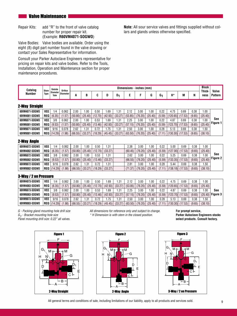
All general terms and conditions of sale, including limitations of our liability, apply to all products and services sold. 9
2-Way Straight 60VM4071-SOGWO VEE 60VM4081-SOGWO REG 60VM6071-SOGWO VEE 60VM6081-SOGWO REG 60VM9071-SOGWO VEE 60VM9081-SOGWO REG
1/4 0.062 2.00 1.00 0.50 1.69 1.31 2.12 3.00 1.00 0.22 4.75 0.69 0.38 1.00 (6.35) (1.57) (50.80) (25.40) (12.70) (42.93) (33.27) (53.85) (76.20) (25.40) (5.59) (120.65) (17.53) (9.65) (25.40) 3/8 0.062 2.00 1.00 0.53 1.69 1.31 2.25 3.00 1.00 0.22 4.87 0.69 0.38 1.00 (9.53) (1.57) (50.80) (25.40) (13.46) (42.93) (33.27) (57.15) (76.20) (25.40) (5.59) (123.70) (17.53) (9.65) (25.40) 9/16 0.078 2.62 1.31 0.72 1.75 1.31 2.50 3.00 1.00 0.28 5.13 0.69 0.38 1.50 (14.29) (1.98) (66.55) (33.27) (18.29) (45.45) (33.27) (63.50) (76.20) (25.40) (7.11) (130.30) (17.53) (9.65) (38.10)
2-Way Angle 60VM4072-SOGWO VEE 60VM4082-SOGWO REG 60VM6072-SOGWO VEE 60VM6082-SOGWO REG 60VM9072-SOGWO VEE 60VM9082-SOGWO REG
1/4 0.062 2.00 1.00 0.50 1.31 2.38 3.00 1.00 0.22 5.00 0.69 0.38 1.00 (6.35) (1.57) (50.80) (25.40) (12.70) (33.27) (60.45) (76.20) (25.40) (5.59) (127.00) (17.53) (9.65) (25.40) 3/8 0.062 2.00 1.00 0.53 1.31 2.62 3.00 1.00 0.22 5.25 0.69 0.38 1.00 (9.53) (1.57) (50.80) (25.40) (13.46) (33.27) (66.55) (76.20) (25.40) (5.59) (133.35) (17.53) (9.65) (25.40) 9/16 0.078 2.62 1.31 0.72 1.31 2.81 3.00 1.00 0.28 5.44 0.69 0.38 1.50 (14.29) (1.98) (66.55) (33.27) (18.29) (33.27) (71.37) (76.20) (25.40) (7.11) (138.18) (17.53) (9.65) (38.10)
3-Way / 2 on Pressure 60VM4073-SOGWO VEE 60VM4083-SOGWO REG 60VM6073-SOGWO VEE 60VM6083-SOGWO REG 60VM9073-SOGWO VEE 60VM9083-SOGWO REG
1/4 0.062 2.00 1.00 0.50 1.69 1.31 2.12 3.00 1.00 0.22 4.75 0.69 0.38 1.00 (6.35) (1.57) (50.80) (25.40) (12.70) (42.93) (33.27) (53.85) (76.20) (25.40) (5.59) (120.65) (17.53) (9.65) (25.40) 3/8 0.062 2.00 1.00 0.53 1.69 1.31 2.25 3.00 1.00 0.22 4.87 0.69 0.38 1.00 (9.53) (1.57) (50.80) (25.40) (13.46) (42.93) (33.27) (57.15) (76.20) (25.40) (5.59) (123.70) (17.53) (9.65) (25.40) 9/16 0.078 2.62 1.31 0.72 1.75 1.31 2.50 3.00 1.00 0.28 5.13 0.69 0.38 1.50 (14.29) (1.98) (66.55) (33.27) (18.29) (45.45) (33.27) (63.50) (76.20) (25.40) (7.11) (130.30) (17.53) (9.65) (38.10)
See Figure 1
See Figure 2
See Figure 3
2-Way Angle 3-Way / 2 on Pressure2-Way Straight
Figure 3Figure 2Figure 1
Valve Maintenance
Note: All sour service valves and fittings supplied without col-lars and glands unless otherwise specified.
Repair Kits: add “R” to the front of valve catalog number for proper repair kit. (Example: R60VM4071-SOGWO)
Valve Bodies: Valve bodies are available. Order using the eight (8) digit part number found in the valve drawing or contact your Sales Representative for information.
Consult your Parker Autoclave Engineers representative for pricing on repair kits and valve bodies. Refer to the Tools, Installation, Operation and Maintenance section for proper maintenance procedures.
Block Thick- Valve A B C D D1 E F G G1 H* M N ness Pattern
Dimensions - inches (mm) Catalog
NumberOutside
DiameterTube
OrificeDiameter
StemType
H N
F
G1
G
D1DE
M M
AB
C
H N
F
G1
G
DE
M M
AB
C
H N
F
G1
G
D1
E
M M
AB
C
D
G - Packing gland mounting hole drill size All dimensions for reference only and subject to change. For prompt service, G1 - Bracket mounting hole size * H Dimension is with stem in the closed position. Parker Autoclave Engineers stocks Panel mounting drill size: 0.22” all valves. select products. Consult factory.

All general terms and conditions of sale, including limitations of our liability, apply to all products and services sold.10
3-Way / 1 on Pressure 60VM4074-SOGWO VEE 60VM4084-SOGWO REG 60VM6074-SOGWO VEE 60VM6084-SOGWO REG 60VM9074-SOGWO VEE 60VM9084-SOGWO REG
1/4 0.062 2.00 1.00 0.50 1.31 2.38 3.00 1.00 0.22 5.00 0.69 0.38 1.00 (6.35) (1.57) (50.80) (25.40) (12.70) (33.27) (60.45) (76.20) (25.40) (5.59) (127.00) (17.53) (9.65) (25.40) 3/8 0.062 2.00 1.00 0.53 1.31 2.62 3.00 1.00 0.22 5.25 0.69 0.38 1.00 (9.53) (1.57) (50.80) (25.40) (13.46) (33.27) (66.55) (76.20) (25.40) (5.59) (133.35) (17.53) (9.65) (25.40) 9/16 0.078 2.62 1.31 0.72 1.31 2.81 3.00 1.00 0.28 5.44 0.69 0.38 1.50 (14.29) (1.98) (66.55) (33.27) (18.29) (33.27) (71.37) (76.20) (25.40) (7.11) (138.18) (17.53) (9.65) (38.10)
2-Way Angle / Replaceable Seat 60VM4872-SOGWO VEE 60VM4882-SOGWO REG 60VM6872-SOGWO VEE 60VM6882-SOGWO REG 60VM9872-SOGWO VEE 60VM9882-SOGWO REG
1/4 0.062 2.00 1.00 0.50 1.31 2.12 2.62 3.00 1.00 0.22 6.28 0.69 0.38 1.00 (6.35) (1.57) (50.80) (25.40) (12.70) (33.27) (53.85) (66.55) (76.20) (25.40) (5.59) (159.51) (17.53) (9.65) (25.40) 3/8 0.062 2.00 1.00 0.53 1.31 2.36 2.62 3.00 1.00 0.22 6.52 0.69 0.38 1.00 (9.53) (1.57) (50.80) (25.40) (13.46) (33.27) (59.94) (66.55) (76.20) (25.40) (5.59) (165.60) (17.53) (9.65) (25.40) 9/16 0.078 2.62 1.31 0.72 1.31 2.68 2.62 3.00 1.00 0.28 6.90 0.69 0.38 1.50 (14.29) (1.98) (66.55) (33.27) (18.29) (33.27) (68.07) (66.55) (76.20) (25.40) (7.11) (175.26) (17.53) (9.65) (38.10)
3-Way / 2-Stem Manifold 60VM4075-SOGWO VEE 60VM4085-SOGWO REG 60VM6075-SOGWO VEE 60VM6085-SOGWO REG 60VM9075-SOGWO VEE 60VM9085-SOGWO REG
1/4 0.062 2.00 1.00 0.50 1.72 1.31 3.44 3.00 1.00 0.22 6.07 0.69 0.38 1.00 (6.35) (1.57) (50.80) (25.40) (12.70) (43.69) (33.27) (87.38) (76.20) (25.40) (5.59) (154.18) (17.53) (9.65) (25.40) 3/8 0.062 2.00 1.00 0.53 1.88 1.31 3.75 3.00 1.00 0.22 6.37 0.69 0.38 1.00 (9.53) (1.57) (50.80) (25.40) (13.46) (47.75) (33.27) (95.25) (76.20) (25.40) (5.59) (161.80) (17.53) (9.65) (25.40) 9/16 0.078 2.62 1.31 0.72 2.06 1.31 4.12 3.00 1.00 0.28 6.37 0.69 0.38 1.50 (14.29) (1.98) (66.55) (33.27) (18.29) (52.32) (33.27) (104.65) (76.20) (25.40) (7.11) (161.80) (17.53) (9.65) (38.10)
See Figure 4
See Figure 5
See Figure 6
2-Way Angle / Replaceable Seat 3-Way / 2 Stem Manifold3-Way / 1 on Pressure
Figure 6Figure 5Figure 4
Block Thick- Valve A B C D D1 E F G G1 H* M N ness Pattern
Dimensions - inches (mm) Catalog
NumberOutside
DiameterTube
OrificeDiameter
StemType
H N
F
G1
G
D
E
M M
AB
C
D
HN
F
G1
G
D
E
M M
AB
C
D1
H N
M M
F
G1
G
D1
E
CBA
D1
D
G - Packing gland mounting hole drill size All dimensions for reference only and subject to change. For prompt service, G1 - Bracket mounting hole size * H Dimension is with stem in the closed position. Parker Autoclave Engineers stocks Panel mounting drill size: 0.22” all valves. select products. Consult factory.
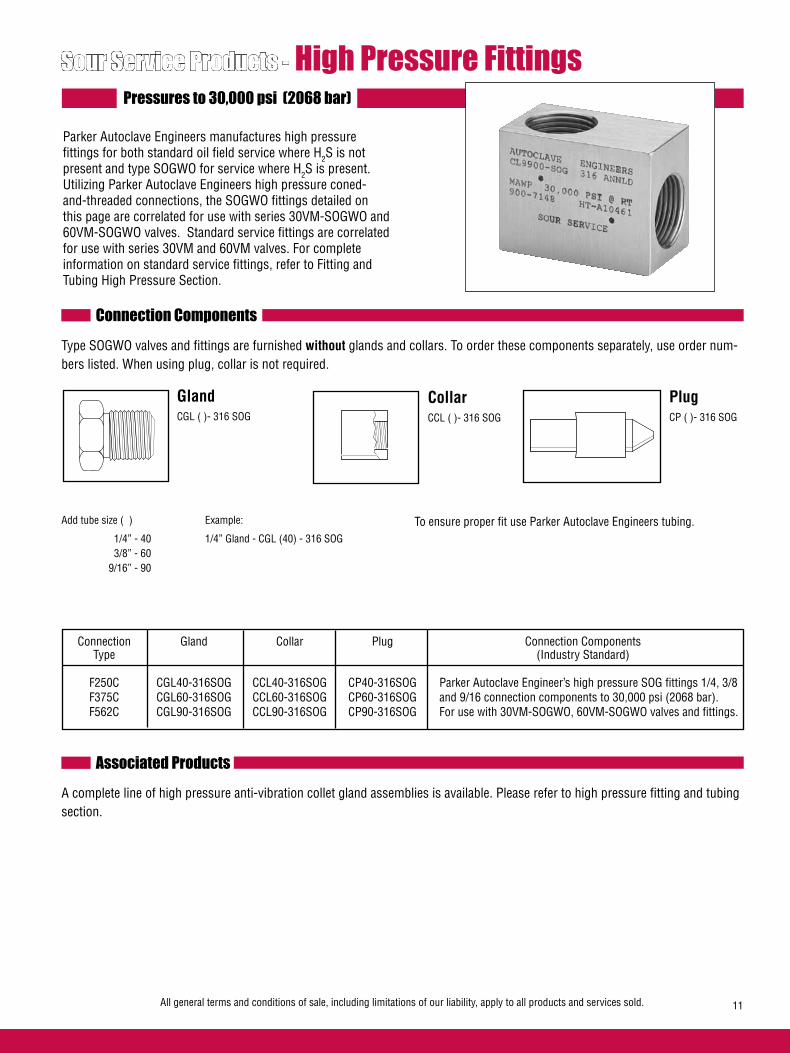
All general terms and conditions of sale, including limitations of our liability, apply to all products and services sold. 11
Sour Service Products - High Pressure Fittings
Parker Autoclave Engineers manufactures high pressure fittings for both standard oil field service where H2S is not present and type SOGWO for service where H2S is present. Utilizing Parker Autoclave Engineers high pressure coned-and-threaded connections, the SOGWO fittings detailed on this page are correlated for use with series 30VM-SOGWO and 60VM-SOGWO valves. Standard service fittings are correlated for use with series 30VM and 60VM valves. For complete information on standard service fittings, refer to Fitting and Tubing High Pressure Section.
Connection Components
To ensure proper fit use Parker Autoclave Engineers tubing.
Gland CGL ( )- 316 SOG
Add tube size ( ) Example:
1/4” - 40 1/4” Gland - CGL (40) - 316 SOG 3/8” - 60 9/16” - 90
Plug CP ( )- 316 SOG
Collar CCL ( )- 316 SOG
Connection Gland Collar Plug Connection Components Type (Industry Standard)
F250C CGL40-316SOG CCL40-316SOG CP40-316SOG Parker Autoclave Engineer’s high pressure SOG fittings 1/4, 3/8 F375C CGL60-316SOG CCL60-316SOG CP60-316SOG and 9/16 connection components to 30,000 psi (2068 bar). F562C CGL90-316SOG CCL90-316SOG CP90-316SOG For use with 30VM-SOGWO, 60VM-SOGWO valves and fittings.
Type SOGWO valves and fittings are furnished without glands and collars. To order these components separately, use order num-bers listed. When using plug, collar is not required.
Pressures to 30,000 psi (2068 bar)
Associated ProductsA complete line of high pressure anti-vibration collet gland assemblies is available. Please refer to high pressure fitting and tubing section.
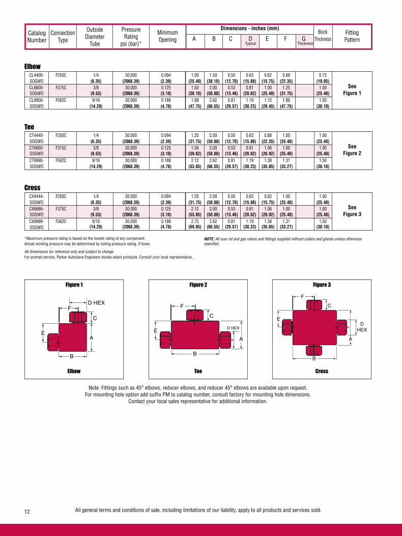
All general terms and conditions of sale, including limitations of our liability, apply to all products and services sold.12
Elbow CL4400- F250C 1/4 30,000 0.094 1.00 1.50 0.50 0.63 0.62 0.88 0.75 SOGWO (6.35) (2068.39) (2.39) (25.40) (38.10) (12.70) (15.88) (15.75) (22.35) (19.05) CL6600- F375C 3/8 30,000 0.125 1.50 2.00 0.53 0.81 1.00 1.25 1.00 SOGWO (9.53) (2068.39) (3.18) (38.10) (50.80) (13.46) (20.62) (25.40) (31.75) (25.40) CL9900- F562C 9/16 30,000 0.188 1.88 2.62 0.81 1.19 1.12 1.88 1.50 SOGWO (14.29) (2068.39) (4.78) (47.75) (66.55) (20.57) (30.23) (28.45) (47.75) (38.10)
See Figure 1
Dimensions - inches (mm)Catalog Number
Connection Type
Outside Diameter
Tube
Pressure Rating
psi (bar)*
Minimum Opening
Block Thickness
Fitting Pattern A B C D E F G
Typical Thickness
Tee CT4440- F250C 1/4 30,000 0.094 1.25 2.00 0.50 0.63 0.88 1.00 1.00 SOGWO (6.35) (2068.39) (2.39) (31.75) (50.80) (12.70) (15.88) (22.35) (25.40) (25.40) CT6660- F375C 3/8 30,000 0.125 1.56 2.00 0.53 0.81 1.06 1.00 1.00 SOGWO (9.53) (2068.39) (3.18) (39.62) (50.80) (13.46) (20.62) (26.92) (25.40) (25.40) CT9990- F562C 9/16 30,000 0.188 2.12 2.62 0.81 1.19 1.38 1.31 1.50 SOGWO (14.29) (2068.39) (4.78) (53.85) (66.55) (20.57) (30.23) (35.05) (33.27) (38.10)
See Figure 2
Cross CX4444- F250C 1/4 30,000 0.094 1.25 2.00 0.50 0.63 0.62 1.00 1.00 SOGWO (6.35) (2068.39) (2.39) (31.75) (50.80) (12.70) (15.88) (15.75) (25.40) (25.40) CX6666- F375C 3/8 30,000 0.125 2.12 2.00 0.53 0.81 1.06 1.00 1.00 SOGWO (9.53) (2068.39) (3.18) (53.85) (50.80) (13.46) (20.62) (26.92) (25.40) (25.40) CX9999- F562C 9/16 30,000 0.188 2.75 2.62 0.81 1.19 1.38 1.31 1.50 SOGWO (14.29) (2068.39) (4.78) (69.85) (66.55) (20.57) (30.23) (35.05) (33.27) (38.10)
See Figure 3
Elbow
Figure 1
Tee
Figure 2
Cross
Figure 3
Note: Fittings such as 45° elbows, reducer elbows, and reducer 45° elbows are available upon request.For mounting hole option add suffix PM to catalog number, consult factory for mounting hole dimensions.
Contact your local sales representative for additional information.
*Maximum pressure rating is based on the lowest rating of any component. Actual working pressure may be determined by tubing pressure rating, if lower.
All dimensions for reference only and subject to change.For prompt service, Parker Autoclave Engineers stocks select products. Consult your local representative.
NOTE: All sour oil and gas valves and fittings supplied without collars and glands unless otherwise specified.
D HEXF
C
A
B
ED HEX
F
C
A
B
ED
HEX
F
C
A
B
E
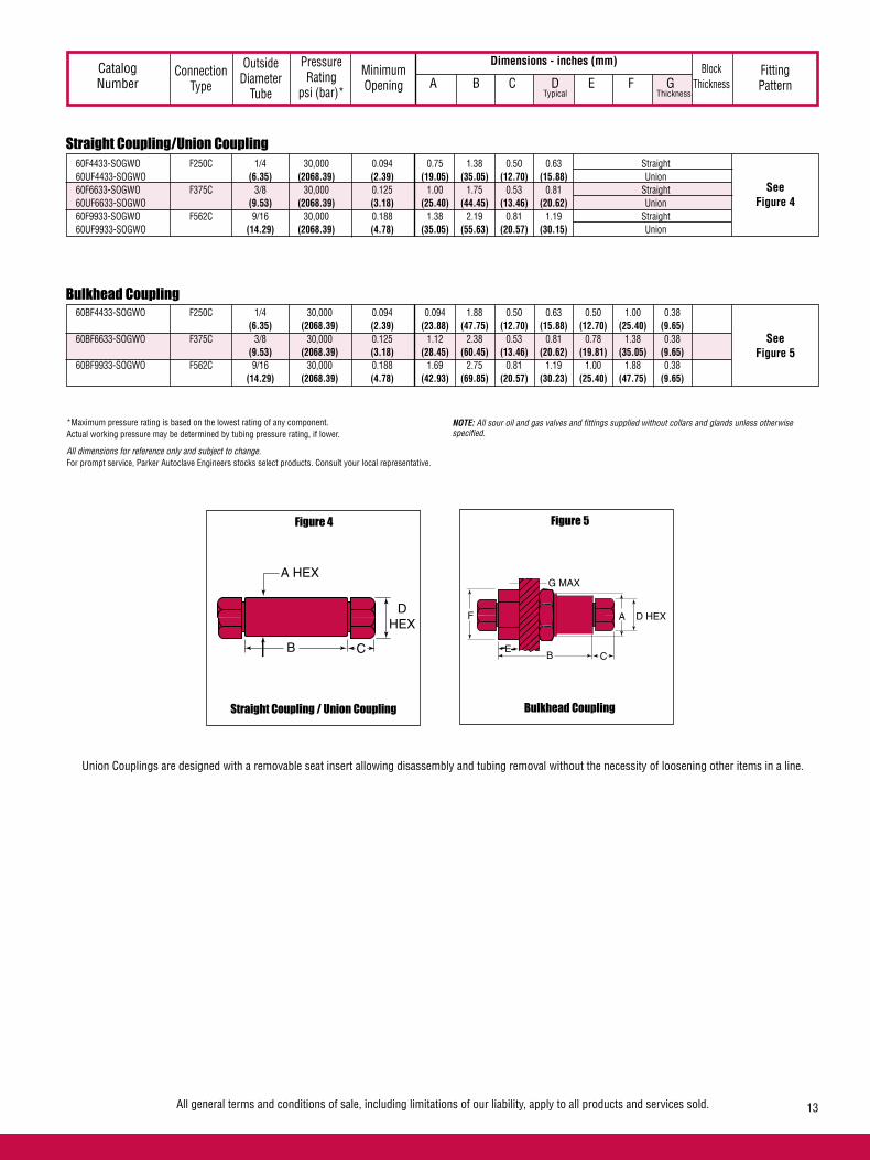
All general terms and conditions of sale, including limitations of our liability, apply to all products and services sold. 13
Straight Coupling/Union Coupling 60F4433-SOGWO F250C 1/4 30,000 0.094 0.75 1.38 0.50 0.63 Straight 60UF4433-SOGWO (6.35) (2068.39) (2.39) (19.05) (35.05) (12.70) (15.88) Union 60F6633-SOGWO F375C 3/8 30,000 0.125 1.00 1.75 0.53 0.81 Straight 60UF6633-SOGWO (9.53) (2068.39) (3.18) (25.40) (44.45) (13.46) (20.62) Union 60F9933-SOGWO F562C 9/16 30,000 0.188 1.38 2.19 0.81 1.19 Straight 60UF9933-SOGWO (14.29) (2068.39) (4.78) (35.05) (55.63) (20.57) (30.15) Union
See Figure 4
Dimensions - inches (mm)Catalog Number
Connection Type
Outside Diameter
Tube
Pressure Rating
psi (bar)*
Minimum Opening
Block Thickness
Fitting Pattern A B C D E F G
Typical Thickness
Bulkhead Coupling 60BF4433-SOGWO F250C 1/4 30,000 0.094 0.094 1.88 0.50 0.63 0.50 1.00 0.38 (6.35) (2068.39) (2.39) (23.88) (47.75) (12.70) (15.88) (12.70) (25.40) (9.65) 60BF6633-SOGWO F375C 3/8 30,000 0.125 1.12 2.38 0.53 0.81 0.78 1.38 0.38 (9.53) (2068.39) (3.18) (28.45) (60.45) (13.46) (20.62) (19.81) (35.05) (9.65) 60BF9933-SOGWO F562C 9/16 30,000 0.188 1.69 2.75 0.81 1.19 1.00 1.88 0.38 (14.29) (2068.39) (4.78) (42.93) (69.85) (20.57) (30.23) (25.40) (47.75) (9.65)
See Figure 5
Union Couplings are designed with a removable seat insert allowing disassembly and tubing removal without the necessity of loosening other items in a line.
Straight Coupling / Union Coupling
Figure 4
Bulkhead Coupling
Figure 5
*Maximum pressure rating is based on the lowest rating of any component. Actual working pressure may be determined by tubing pressure rating, if lower.
All dimensions for reference only and subject to change.For prompt service, Parker Autoclave Engineers stocks select products. Consult your local representative.
NOTE: All sour oil and gas valves and fittings supplied without collars and glands unless otherwise specified.
DHEX
CB
A HEXG MAX
CB
F
E
A D HEX
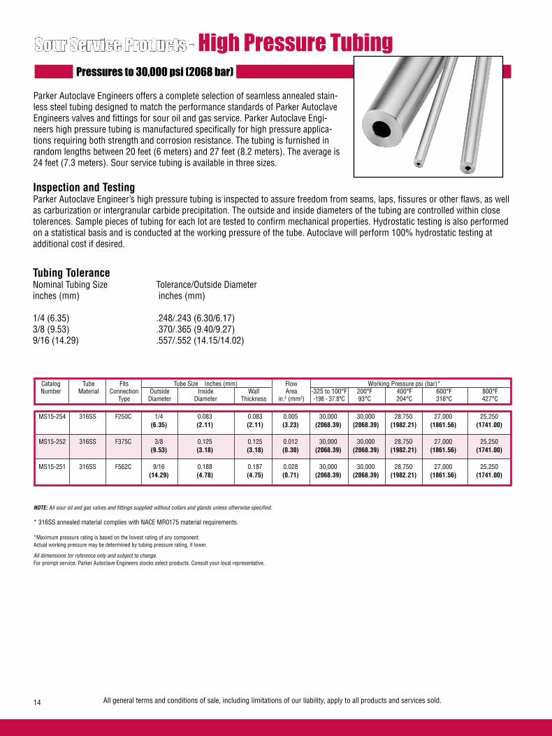
All general terms and conditions of sale, including limitations of our liability, apply to all products and services sold.14
Pressures to 30,000 psi (2068 bar)
Parker Autoclave Engineers offers a complete selection of seamless annealed stain-less steel tubing designed to match the performance standards of Parker Autoclave Engineers valves and fittings for sour oil and gas service. Parker Autoclave Engi-neers high pressure tubing is manufactured specifically for high pressure applica-tions requiring both strength and corrosion resistance. The tubing is furnished in random lengths between 20 feet (6 meters) and 27 feet (8.2 meters). The average is 24 feet (7.3 meters). Sour service tubing is available in three sizes.
Catalog Tube Fits Tube Size Inches (mm) Flow Working Pressure psi (bar)* Number Material Connection Outside Inside Wall Area -325 to 100°F 200°F 400°F 600°F 800°F Type Diameter Diameter Thickness in.2 (mm2) -198 - 37.8°C 93°C 204°C 316°C 427°C
Tubing ToleranceNominal Tubing Size Tolerance/Outside Diameterinches (mm) inches (mm) 1/4 (6.35) .248/.243 (6.30/6.17)3/8 (9.53) .370/.365 (9.40/9.27)9/16 (14.29) .557/.552 (14.15/14.02)
MS15-254 316SS F250C 1/4 0.083 0.083 0.005 30,000 30,000 28,750 27,000 25,250 (6.35) (2.11) (2.11) (3.23) (2068.39) (2068.39) (1982.21) (1861.56) (1741.00) MS15-252 316SS F375C 3/8 0.125 0.125 0.012 30,000 30,000 28,750 27,000 25,250 (9.53) (3.18) (3.18) (0.30) (2068.39) (2068.39) (1982.21) (1861.56) (1741.00) MS15-251 316SS F562C 9/16 0.188 0.187 0.028 30,000 30,000 28,750 27,000 25,250 (14.29) (4.78) (4.75) (0.71) (2068.39) (2068.39) (1982.21) (1861.56) (1741.00)
Sour Service Products - High Pressure Tubing
NOTE: All sour oil and gas valves and fittings supplied without collars and glands unless otherwise specified.
* 316SS annealed material complies with NACE MR0175 material requirements. *Maximum pressure rating is based on the lowest rating of any component. Actual working pressure may be determined by tubing pressure rating, if lower.
All dimensions for reference only and subject to change.For prompt service, Parker Autoclave Engineers stocks select products. Consult your local representative.
Inspection and TestingParker Autoclave Engineer’s high pressure tubing is inspected to assure freedom from seams, laps, fissures or other flaws, as well as carburization or intergranular carbide precipitation. The outside and inside diameters of the tubing are controlled within close tolerences. Sample pieces of tubing for each lot are tested to confirm mechanical properties. Hydrostatic testing is also performed on a statistical basis and is conducted at the working pressure of the tube. Autoclave will perform 100% hydrostatic testing at additional cost if desired.

All general terms and conditions of sale, including limitations of our liability, apply to all products and services sold. 15
Sour Service Products - High Pressure Coned-and-Threaded Nipples
For rapid system make-up, Parker Autoclave Engineers supplies pre-cut, coned-and-threaded nipples in various sizes and lengths for Parker Autoclave Engineers high pressure valves and fittings.
Special lengthsIn addition to the standard lengths listed in the table below, nipples are available in any custom length. Consult factory.
MaterialsCatalog numbers in table refer to Type 316 Stainless steel.Catalog numbers with suffix 316SOG denote 316SS annealed in compliance with NACE MR0175.
Catalog Number Nipple Length In (mm)
2.75” 3.00” 4.00” 6.00” 8.00” 10.00” 12.00” (69.85) (76.20) (101.60) (152.40) (203.20) (254.00) (304.80) O.D. I.D.
CN4402- CN4403- CN4404- CN4406- CN4408- CN44010- CN44012- F250C 1/4 0.083 30,000 316SOG 316SOG 316SOG 316SOG 316SOG 316SOG 316SOG (6.35) (2.11) (2068.39)
CN6603- CN6604- CN6606- CN6608- CN66010- CN66012- F375C 3/8 0.125 30,000 316SOG 316SOG 316SOG 316SOG 316SOG 316SOG (9.53) (3.18) (2068.39)
CN9904- CN9906- CN9908- CN99010- CN99012- F562C 9/16 0.188 30,000 316SOG 316SOG 316SOG 316SOG 316SOG (14.29) (4.78) (2068.39)
FitsConnection
Type
WorkingPressure
at 100°F (37.8°C)psi (bar)
Tube Size inches(mm)
Note: 1. See Sour Service tubing section for pressure ratings at various temperatures. 2. Parker Autocalve Engineers does not recommend bending of SOG tubing.
Material in table is 316 Stainless steel
*Maximum pressure rating is based on the lowest rating of any component. Actual working pressure may be determined by tubing pressure rating, if lower.
All dimensions for reference only and subject to change.For prompt service, Parker Autoclave Engineers stocks select products. Consult your local representative.
Pressures to 30,000 psi (2068 bar)

All general terms and conditions of sale, including limitations of our liability, apply to all products and services sold.16
Sour Service Products - High Pressure Check ValvesPressures to 30,000 (2068 bar)
Provides unidirectional flow and tight shut-off for liquids and gas with high reliability. When differential drops below crack-ing pressure*, valve shuts off. (Not for use as relief valve.)
Materials: Body, cover, poppet: 316 Annealed Stainless Steel, Cover gland: Annealed Stainless Steel, Spring: High Nickel Alloy, Standard O-ring: Viton, for operation to 400° F (204°C). Buna-N or PTFE available for 250°F (121°C) or 400°F (204°C) respectively; specify when ordering.
*Cracking Pressure: 20 psi (1.38 bar) ±30%. Springs for higher cracking pressures (up to 100 psi (6.89 bar)) available on special order for O-ring style check valves only.
Prevents reverse flow where leak-tight shut-off is not manda-tory. When differential drops below cracking pressure, valve closes. With all-metal components, valve can be used up to 1200°F (649°C). See Technical Information section for connection temperature limitations. (Not for use as a relief valve.)Ball and poppet are an integral design to assure positive, in-line seating without “chatter”. Poppet is designed essentially for axial flow with minimum pressure drop.Materials: Body, cover, poppet: 316 Annealed Stainless Steel, Cover gland: Annealed Stainless Steel, Ball, Spring: High Nickel Alloy
Protects pressure gauges and pressure instrumentation from surges in flow or sudden venting in the event of line failure.Materials: Body, cover, sleeve: Type 316 Annealed Stainless Steel, Ball: 300 Series Annealed Stainless Steel, Cover gland: annealed stainless steel.Vertical Installation: Since this type of check valve employs a non-spring loaded ball, valve MUST be installed in VERTICAL position with arrow on valve body pointing UP. (cover gland up).Resetting Valve: Equalize the pressure across the ball. The ball will drop and reset automatically.
O-Ring Check Valves
Ball Check Valves
Ball Type Excess Flow Valves
NOTE: All sour oil and gas valves and fittings supplied without collars and glands unless otherwise specified.
CAUTION: While testing has shown O-Rings to provide satisfactory service life, both cyclic and shelf life may vary widely with differing service conditions, properties of reactants, pressure and temperature cycling and age of the O-ring. FREQUENT INSPECTIONS SHOULD BE MADE to detect any deterioration, and O-rings replaced as required.
FLOW
FLOW
FLO
W
(Vertical Installation O
nly)
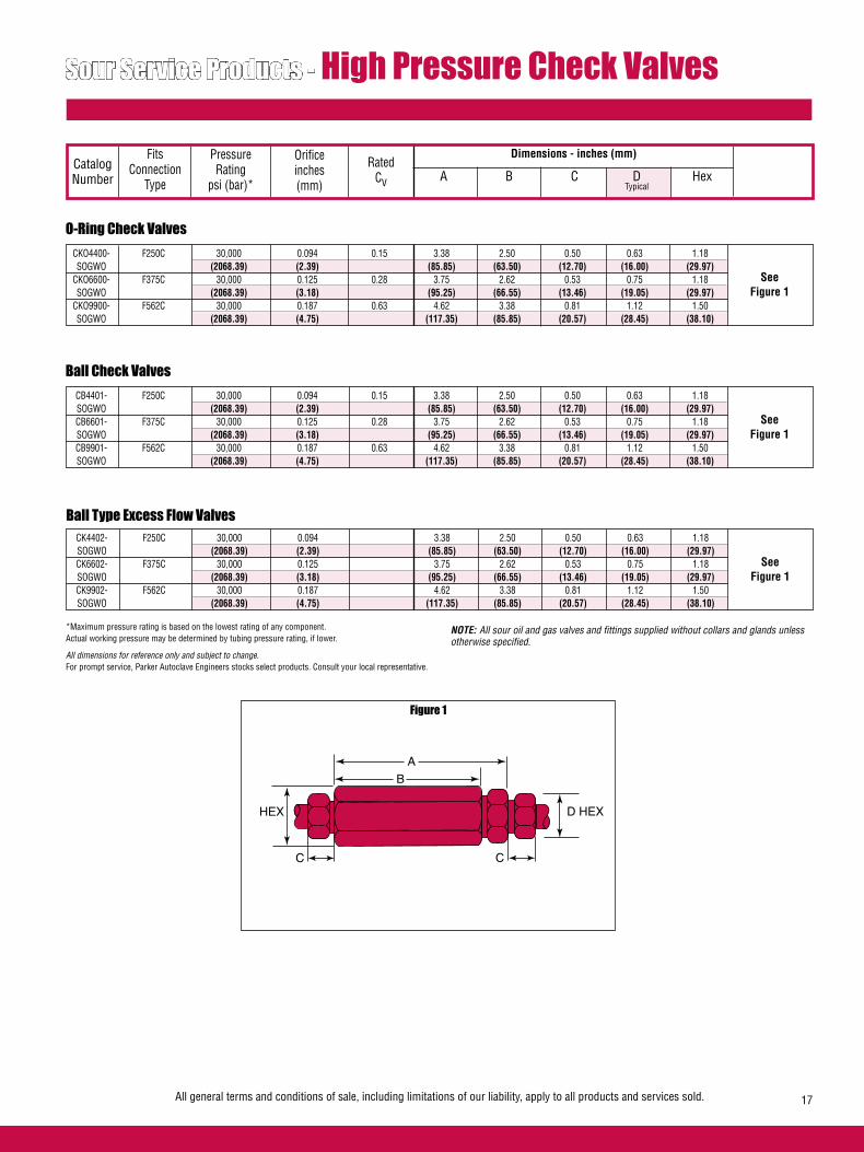
All general terms and conditions of sale, including limitations of our liability, apply to all products and services sold. 17
O-Ring Check Valves CKO4400- F250C 30,000 0.094 0.15 3.38 2.50 0.50 0.63 1.18 SOGWO (2068.39) (2.39) (85.85) (63.50) (12.70) (16.00) (29.97) CKO6600- F375C 30,000 0.125 0.28 3.75 2.62 0.53 0.75 1.18 SOGWO (2068.39) (3.18) (95.25) (66.55) (13.46) (19.05) (29.97) CKO9900- F562C 30,000 0.187 0.63 4.62 3.38 0.81 1.12 1.50 SOGWO (2068.39) (4.75) (117.35) (85.85) (20.57) (28.45) (38.10)
Dimensions - inches (mm)
Sour Service Products - High Pressure Check Valves
See Figure 1
Catalog Number
Fits Connection
Type
Orifice inches (mm)
Pressure Rating
psi (bar)*
Rated Cv A B C D Hex
Typical
Figure 1
Ball Check Valves CB4401- F250C 30,000 0.094 0.15 3.38 2.50 0.50 0.63 1.18 SOGWO (2068.39) (2.39) (85.85) (63.50) (12.70) (16.00) (29.97) CB6601- F375C 30,000 0.125 0.28 3.75 2.62 0.53 0.75 1.18 SOGWO (2068.39) (3.18) (95.25) (66.55) (13.46) (19.05) (29.97) CB9901- F562C 30,000 0.187 0.63 4.62 3.38 0.81 1.12 1.50 SOGWO (2068.39) (4.75) (117.35) (85.85) (20.57) (28.45) (38.10)
See Figure 1
Ball Type Excess Flow Valves CK4402- F250C 30,000 0.094 3.38 2.50 0.50 0.63 1.18 SOGWO (2068.39) (2.39) (85.85) (63.50) (12.70) (16.00) (29.97) CK6602- F375C 30,000 0.125 3.75 2.62 0.53 0.75 1.18 SOGWO (2068.39) (3.18) (95.25) (66.55) (13.46) (19.05) (29.97) CK9902- F562C 30,000 0.187 4.62 3.38 0.81 1.12 1.50 SOGWO (2068.39) (4.75) (117.35) (85.85) (20.57) (28.45) (38.10)
See Figure 1
*Maximum pressure rating is based on the lowest rating of any component. Actual working pressure may be determined by tubing pressure rating, if lower.
All dimensions for reference only and subject to change.For prompt service, Parker Autoclave Engineers stocks select products. Consult your local representative.
NOTE: All sour oil and gas valves and fittings supplied without collars and glands unless otherwise specified.
HEX
C
B
A
C
D HEX
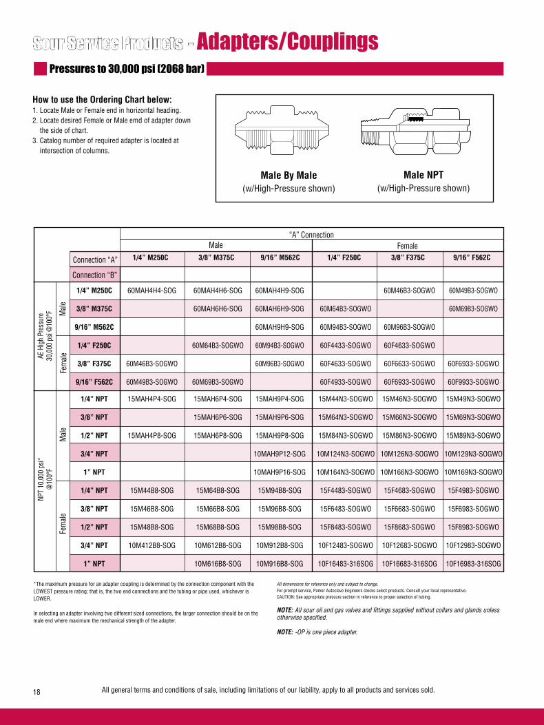
All general terms and conditions of sale, including limitations of our liability, apply to all products and services sold.18
Sour Service Products - Adapters/Couplings
How to use the Ordering Chart below: 1. Locate Male or Female end in horizontal heading.2. Locate desired Female or Male emd of adapter down the side of chart.3. Catalog number of required adapter is located at intersection of columns.
“A” ConnectionMale
AE H
igh
Pres
sure
30,0
00 p
si @
100°
F
*The maximum pressure for an adapter coupling is determined by the connection component with the LOWEST pressure rating; that is, the two end connections and the tubing or pipe used, whichever is LOWER.
In selecting an adapter involving two different sized connections, the larger connection should be on the male end where maximum the mechanical strength of the adapter.
Pressures to 30,000 psi (2068 bar)
Female
Connection “B”
Connection “A”
Male
Fem
ale
NPT
10,0
00 p
si*@
100°
F
Male
Fem
ale
1/4” M250C 3/8” M375C 9/16” M562C 1/4” F250C 3/8” F375C 9/16” F562C
1/4” M250C 60MAH4H4-SOG 60MAH4H6-SOG 60MAH4H9-SOG 60M46B3-SOGWO 60M49B3-SOGWO
3/8” M375C 60MAH6H6-SOG 60MAH6H9-SOG 60M64B3-SOGWO 60M69B3-SOGWO
9/16” M562C 60MAH9H9-SOG 60M94B3-SOGWO 60M96B3-SOGWO
1/4” F250C 60M64B3-SOGWO 60M94B3-SOGWO 60F4433-SOGWO 60F4633-SOGWO
3/8” F375C 60M46B3-SOGWO 60M96B3-SOGWO 60F4633-SOGWO 60F6633-SOGWO 60F6933-SOGWO
9/16” F562C 60M49B3-SOGWO 60M69B3-SOGWO 60F4933-SOGWO 60F6933-SOGWO 60F9933-SOGWO
1/4” NPT 15MAH4P4-SOG 15MAH6P4-SOG 15MAH9P4-SOG 15M44N3-SOGWO 15M46N3-SOGWO 15M49N3-SOGWO
3/8” NPT 15MAH6P6-SOG 15MAH9P6-SOG 15M64N3-SOGWO 15M66N3-SOGWO 15M69N3-SOGWO
1/2” NPT 15MAH4P8-SOG 15MAH6P8-SOG 15MAH9P8-SOG 15M84N3-SOGWO 15M86N3-SOGWO 15M89N3-SOGWO
3/4” NPT 10MAH9P12-SOG 10M124N3-SOGWO 10M126N3-SOGWO 10M129N3-SOGWO
1” NPT 10MAH9P16-SOG 10M164N3-SOGWO 10M166N3-SOGWO 10M169N3-SOGWO
1/4” NPT 15M44B8-SOG 15M64B8-SOG 15M94B8-SOG 15F4483-SOGWO 15F4683-SOGWO 15F4983-SOGWO
3/8” NPT 15M46B8-SOG 15M66B8-SOG 15M96B8-SOG 15F6483-SOGWO 15F6683-SOGWO 15F6983-SOGWO
1/2” NPT 15M48B8-SOG 15M68B8-SOG 15M98B8-SOG 15F8483-SOGWO 15F8683-SOGWO 15F8983-SOGWO
3/4” NPT 10M412B8-SOG 10M612B8-SOG 10M912B8-SOG 10F12483-SOGWO 10F12683-SOGWO 10F12983-SOGWO
1” NPT 10M616B8-SOG 10M916B8-SOG 10F16483-316SOG 10F16683-316SOG 10F16983-316SOG
All dimensions for reference only and subject to change.For prompt service, Parker Autoclave Engineers stocks select products. Consult your local representative.CAUTION: See appropriate pressure section in reference to proper selection of tubing.
NOTE: All sour oil and gas valves and fittings supplied without collars and glands unless otherwise specified. NOTE: -OP is one piece adapter.
Male NPT(w/High-Pressure shown)
Male By Male(w/High-Pressure shown)

All general terms and conditions of sale, including limitations of our liability, apply to all products and services sold. 19
Sour Service Products - Severe Service ValvePressures to 10,000 psi (690 bar)
Parker Autoclave Engineers' severe service valve is designed for reliable shut-off service with maximum working pressure to 10,000 psi (690 bar). They are suitable for a wide range of severe duty applications and comply with NACE MR0175. The valve’s unique stem design includes a non-rotation ball point as well as blow-out protection.
Applications: • All areas where reliable shut-off is required in severe service including abrasive, erosive, corrosive and sour fluids. • Sampling and blowdown lines. • Blow-out preventers • Wireline service equipment • Chemical processing industry
Parker Autoclave Engineers service valves feature: • Low operating torque • Non-rotating tungsten carbide (ball point) stem • Stem back seat for blow-out prevention • Dust seal prevents stem thread contamination • Stem packing adjustment not required • Complies with NACE MR0175 • Moly lubricated stem threads • Panel mount option available
Aluminum Handle
Viton™Dust Seal
Metal-to-metalBack Seat
Hytrel™seals
Body - 316SS
Ball PointTungsten Carbide
Bonnet SS
Stem - 316SS
Packing WashersAluminum Bronze
Snap RingPH 15-7MO
All valves 100% factory tested
Maximum Valve Working Size Orifice Rated Pressure (inches) inches (mm) Cv psi (bar)
1/4 .188 (4.76) .61 10,000 (690) 1/2 .250 (6.35) .78 10,000 (690) 3/4 .375 (9.53) 1.79 7,500 (517)
Operating temperature: -20°F to 275°F (-29°C to 135°C)

All general terms and conditions of sale, including limitations of our liability, apply to all products and services sold.20
2-Way Straight 1/4” male 1/4” Female 3.00 1.75 - 1.25 .625 3.25 3.41 0.75 2.50 (76.20) (44.45) - (31.75) (15.88) (82.55) (86.51) (19.05) (63.50) 1/4” Female 1/4” Female 3.00 1.50 - 1.25 0.63 3.25 3.41 0.75 2.50 (76.20) (38.10) - (31.75) (15.88) (82.55) (86.51) (19.05) (63.50) 1/2” Male 1/2” Female 3.81 2.22 - 1.50 0.75 4.25 4.41 1.00 3.25 (96.82) (56.34) - (38.10) (19.05) (107.95) (111.91) (25.40) (82.55) 1/2” Female 1/2” Female 3.81 1.91 - 1.50 0.75 4.25 4.41 1.00 3.25 (96.82) (48.41) - (38.10) (19.05) (107.95) (111.91) (25.40) (82.55) 3/4” Male 3/4” Female 3.81 2.19 - 1.75 0.88 4.94 5.13 1.00 3.25 (96.82) (55.55) - (44.45) (22.23) (125.40) (130.18) (25.40) (82.55) 3/4” Female 3/4” Female 3.81 1.91 - 1.75 0.88 4.94 5.13 1.00 3.25 (96.82) (48.41) - (44.45) (22.23) (125.40) (130.18) (25.40) (82.55)
See Figure 1
2-Way Angle2-Way Straight
Figure 2Figure 1
All dimensions for reference only and subject to change. For prompt service, Parker Autoclave Engineers stocks select products. Consult factory.
Valve Pattern A B C D E F G H J
Dimensions - inches (mm) Catalog
Number InletN.P.T.
OutletN.P.T.
End Connection
SSV71F8
2-Way Angle 1/4” Female 1/4” Male 3.75 1.63 1.16 1.25 0.63 3.25 3.41 0.75 2.50 (95.25) (41.28) (29.36) (31.75) (15.88) (82.55) (86.51) (19.05) (63.50) 1/4” Female 1/4” Female 3.00 1.63 1.16 1.25 0.63 3.25 3.41 0.75 2.50 (76.20) (41.28) (29.63) (31.75) (15.88) (82.55) (86.51) (19.05) (63.50) 1/2” Female 1/2” Male 4.25 2.03 1.28 1.50 0.75 4.25 4.41 1.00 3.25 (107.95) (51.59) (32.54) (38.10) (19.05) (107.95) (111.91) (25.40) (82.55) 1/2” Female 1/2” Female 3.81 2.00 1.28 1.50 0.75 4.25 4.41 1.00 3.25 (96.82) (50.80) (32.54) (38.10) (19.05) (107.95) (111.91) (25.40) (82.55) 3/4” Female 3/4” Male 4.94 2.75 2.00 1.75 0.88 4.94 5.13 1.00 3.25 (125.40) (69.85) (50.80) (44.45) (22.23) (125.40) (130.18) (25.40) (82.55) 3/4” Female 3/4” Female 4.50 2.75 2.00 1.75 0.88 4.94 5.13 1.00 3.25 (114.30) (69.85) (50.80) (44.45) (22.23) (125.40) (130.18) (25.40) (82.55)
See Figure 2
All general terms and conditions of sale, including limitations of our liability, apply to all products and service sold.
GOpen
FClosed
J
BA
D(Square)
H(Diameter)
E
Inlet InletC
SSV71M4F4
SSV71F4
SSV71M8F8
SSV71M12F12
SSV71F12
SSV72F8
SSV72M4F4
SSV721F4
SSV72M8F8
SSV72M12F12
SSV72F12

All general terms and conditions of sale, including limitations of our liability, apply to all products and services sold. 21
Sour Service Products - Pressure Gauges
Material and Features:
• Accuracy within 1.0% of full scale range
• Stainless steel case and ring
• K-Monel Bourdon tube and socket
• M562C male 9/16” tube connection in bottom (API Type III)
• Precision stainless steel movement for accuracy and resistance to atmospheric corrosion.
• Pointer zero adjustment located on front of gauge behind dial cover for convenience.
• Gauges can be liquid filled (Add - LF to Catalog #)*
• All gauges furnished with SOG collar and gland
• Gauges are NACE MR175-2002
Pressures to 20,000 psi (1379 bar)
Calibrated in PSI Only Minor Interval Dial Catalog Pressure Value Diameter Number psi (bar) psi (bar) inches (mm)
H-0380 0-5000 (345) 50 (3.45) 4-1/2 (114.30) H-0336 0-10,000 (690) 100 (6.90) 4-1/2 (114.30) H-0071 0-15,000 (1034) 100 (6.90) 4-1/2 (114.30) H-0304 0-20,000 (1379) 200 (13.79) 4-1/2 (114.30) H-0360 0-30,000 (2068) 500 (34.5) 4-1/2 (114.30)
* Glycerine is standard liquid fill for “LF” option.


02-0136SE January2013© 2013 Parker Hannifin Corporation | Autoclave Engineers is a registered trademark of the Parker Hannifin Corporation
Parker Hannifin Manufacturing Ltd. Instrumentation Products Division, Europe Industrial Estate WhitemillWexford, Republic of IrelandPH: 353 53 914 1566FAX: 353 53 914 1582
Instrumentation Products DivisionAutoclave Engineers Operation8325 Hessinger DriveErie, Pennsylvania 16509-4679 USAPH: 814-860-5700 FAX: 814-860-5811www.autoclave.com
WARNING
FAILURE, IMPROPER SELECTION OR IMPROPER USE OF THE PRODUCTS AND/OR SYSTEMS DESCRIBED HEREIN OR RELATED ITEMS CAN CAUSE DEATH, PERSONAL INJURY AND PROPERTY DAMAGE.This document and other information from Parker Hannifin Corporation, its subsidiaries and authorized distributors provide product and/or system options for further investigation by users having technical expertise. It is important that you analyze all aspects of your application and review the information concerning the product or system in the current product catalog. Due to the variety of operating conditions and applications for these products or systems, the user, through its own analysis and testing, is solely responsible for making the final selection of the products and systems and assuring that all performance, safety and warning requirements of the application are met. The products described herein, including without limitation, product features, specifications, designs, availability and pricing, are subject to change by Parker Hannifin Corporation and its subsidiaries at any time without notice.
Offer of Sale
The items described in this document are available for sale by Parker Hannifin Corporation, its subsidiaries or its authorized distributors. Any sale contract entered by Parker will be governed by the provisions stated in Parker's standard terms and conditions of sale (copy available upon request).
ISO-9001 Certified
Caution! Do not mix or interchange parts or tubing with those of other manufacturers. Doing so is unsafe and will void warranty.
Caution! Parker Autoclave Engineers Valves, Fittings and Tools are not designed to work with common commercial instrument tubing and will only work with tubing built to Parker Autoclave Engineers AES Specifications. Failure to do so will void warranty.
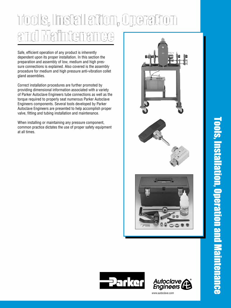
1All general terms and conditions of sale, including limitations of our liability, apply to all products and services sold.
Safe, efficient operation of any product is inherently dependent upon its proper installation. In this section the preparation and assembly of low, medium and high pres-sure connections is explained. Also covered is the assembly procedure for medium and high pressure anti-vibration collet gland assemblies.
Correct installation procedures are further promoted by providing dimensional information associated with a variety of Parker Autoclave Engineers tube connections as well as the torque required to properly seat numerous Parker Autoclave Engineers components. Several tools developed by Parker Autoclave Engineers are presented to help accomplish proper valve, fitting and tubing installation and maintenance.
When installing or maintaining any pressure component, common practice dictates the use of proper safety equipment at all times.
Tools, Installation, Operationand Maintenance
Tools, Installation, Operation and Maintenance
www.autoclave.com

2 All general terms and conditions of sale, including limitations of our liability, apply to all products and services sold.
Tools, Installation, Operation and Maintenance - InstallationParker Autoclave Engineers Speedbite Connections
Fast, Positive Sealing for Pressures up to 15,000 psi* (1034 bar) 1. Cut tubing to length and deburr. Allow extra length for proper engagement (per table below).
Outside Diameter Extra Allowance** Tube Size for Engagement inches (mm) inches (mm)
1/16 (1.59) 0.50 (12.70)
1/8 (3.18) 0.50 (12.70)
1/4 (6.35) 0.75 (19.05)
3/8 (9.53) 0.75 (19.05)
1/2 (12.70) 0.88 (22.35)
2. Lubricate male threads. (Lubrication not necessary if tube nut has Bonded Dry-Film Lubricant.) Slip gland and sleeve onto tubing.Note: Be sure to remove gland and sleeve from components and slide them onto the tubing before inserting the tubing into the components. Make sure larger end of sleeve is toward gland. Push tubing into valve or fitting until it bottoms. If process tolerable, a slight amount of inert grease on the nose of the compression sleeve will improve sealability.
3. TIGHTEN GLAND UNTIL SLEEVE BEGINS TO GRIP TUBING.
4. Note starting position of wrench. Tighten gland approxi-mately 1-1/4 turns for the SW and 1/8" W connection. For 1/4" and 1/2" W connections tighten glands approximately 1 turn.
Step 1 Step 2
Step 3 Step 4
Complete Connection
The illustration below shows the condition of sleeve and tubing after completion of “sleeve seating.” The sleeve has cut into the tubing as it moved forward into the tapered seat, upsetting material ahead of it and establishing a shoulder on the tubing to provide positive mechanical support for the tubing end-load. A properly seated sleeve cannot be displaced back and forth along the tubing but may be rotated around the tubing.
Reassembly
To reassemble a connection, insert tubing with sleeve and gland into valve or fitting. Tighten gland “finger-tight”. Tighten gland with a wrench approximately 3/8 of a turn for a gas-tight seal. After frequent reassemblies, it may take less than 3/8 turn to effect a gas-tight seal, and as little as 1/8 of a turn may be sufficient.
* No special torque wrenches or mandrels required.
** Distance tubing protrudes into connection from face of fitting.
Fully annealed tubing with proper outside diameter tolerences is recommended for these connection components.
Bite into tubing exaggerated for clarity
SpeedBite "SW" and "W" Style
Larger end of sleeve toward gland
Gland
Fitting
See Note **
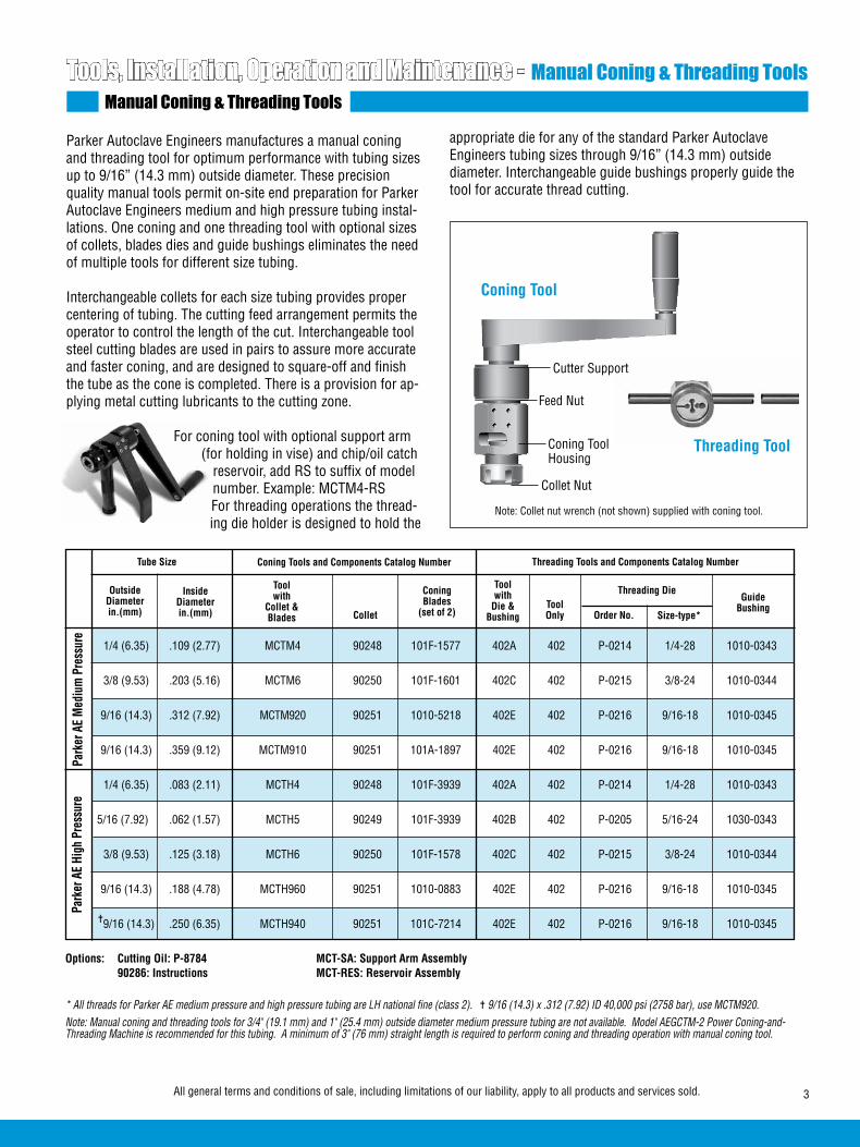
3All general terms and conditions of sale, including limitations of our liability, apply to all products and services sold.
Tools, Installation, Operation and Maintenance - Manual Coning & Threading ToolsManual Coning & Threading Tools
Parker Autoclave Engineers manufactures a manual coning and threading tool for optimum performance with tubing sizes up to 9/16” (14.3 mm) outside diameter. These precision quality manual tools permit on-site end preparation for Parker Autoclave Engineers medium and high pressure tubing instal-lations. One coning and one threading tool with optional sizes of collets, blades dies and guide bushings eliminates the need of multiple tools for different size tubing.
Interchangeable collets for each size tubing provides proper centering of tubing. The cutting feed arrangement permits the operator to control the length of the cut. Interchangeable tool steel cutting blades are used in pairs to assure more accurate and faster coning, and are designed to square-off and finish the tube as the cone is completed. There is a provision for ap-plying metal cutting lubricants to the cutting zone.
For coning tool with optional support arm (for holding in vise) and chip/oil catch
reservoir, add RS to suffix of model number. Example: MCTM4-RSFor threading operations the thread-ing die holder is designed to hold the
Coning Tools and Components Catalog NumberTube Size
OutsideDiameterin.(mm)
InsideDiameterin.(mm)
Toolwith
Collet &Blades
Toolwith
Die &Bushing
ConingBlades
(set of 2)ToolOnly
Guide Bushing
Size-type*Order No.
Threading Tools and Components Catalog Number
Threading Die
Park
er A
E Hi
gh P
ress
ure
Park
er A
E M
ediu
m P
ress
ure
1/4 (6.35) .109 (2.77) MCTM4 90248 101F-1577 402A 402 P-0214 1/4-28 1010-0343
3/8 (9.53) .203 (5.16) MCTM6 90250 101F-1601 402C 402 P-0215 3/8-24 1010-0344
9/16 (14.3) .312 (7.92) MCTM920 90251 1010-5218 402E 402 P-0216 9/16-18 1010-0345
9/16 (14.3) .359 (9.12) MCTM910 90251 101A-1897 402E 402 P-0216 9/16-18 1010-0345
1/4 (6.35) .083 (2.11) MCTH4 90248 101F-3939 402A 402 P-0214 1/4-28 1010-0343
5/16 (7.92) .062 (1.57) MCTH5 90249 101F-3939 402B 402 P-0205 5/16-24 1030-0343
3/8 (9.53) .125 (3.18) MCTH6 90250 101F-1578 402C 402 P-0215 3/8-24 1010-0344
9/16 (14.3) .188 (4.78) MCTH960 90251 1010-0883 402E 402 P-0216 9/16-18 1010-0345
=9/16 (14.3) .250 (6.35) MCTH940 90251 101C-7214 402E 402 P-0216 9/16-18 1010-0345
Options: Cutting Oil: P-8784 MCT-SA: Support Arm Assembly 90286: Instructions MCT-RES: Reservoir Assembly
* All threads for Parker AE medium pressure and high pressure tubing are LH national fine (class 2). = 9/16 (14.3) x .312 (7.92) ID 40,000 psi (2758 bar), use MCTM920. Note: Manual coning and threading tools for 3/4" (19.1 mm) and 1" (25.4 mm) outside diameter medium pressure tubing are not available. Model AEGCTM-2 Power Coning-and-Threading Machine is recommended for this tubing. A minimum of 3" (76 mm) straight length is required to perform coning and threading operation with manual coning tool.
Collet
Coning Tool
Threading Tool
Cutter Support
Feed Nut
Coning Tool Housing
Collet Nut
appropriate die for any of the standard Parker Autoclave Engineers tubing sizes through 9/16” (14.3 mm) outside diameter. Interchangeable guide bushings properly guide the tool for accurate thread cutting.
Note: Collet nut wrench (not shown) supplied with coning tool.
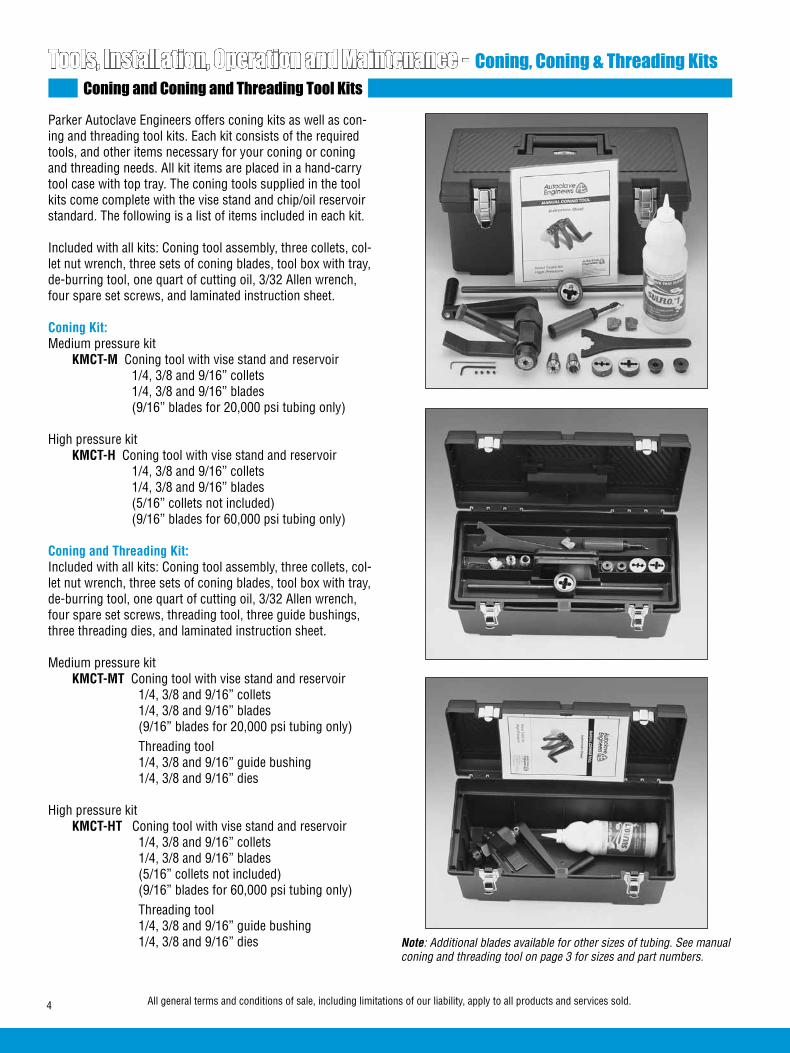
4 All general terms and conditions of sale, including limitations of our liability, apply to all products and services sold.
Tools, Installation, Operation and Maintenance - Coning, Coning & Threading KitsConing and Coning and Threading Tool Kits
Parker Autoclave Engineers offers coning kits as well as con-ing and threading tool kits. Each kit consists of the required tools, and other items necessary for your coning or coning and threading needs. All kit items are placed in a hand-carry tool case with top tray. The coning tools supplied in the tool kits come complete with the vise stand and chip/oil reservoir standard. The following is a list of items included in each kit.
Included with all kits: Coning tool assembly, three collets, col-let nut wrench, three sets of coning blades, tool box with tray, de-burring tool, one quart of cutting oil, 3/32 Allen wrench, four spare set screws, and laminated instruction sheet.
Coning Kit: Medium pressure kit KMCT-M Coning tool with vise stand and reservoir 1/4, 3/8 and 9/16” collets 1/4, 3/8 and 9/16” blades (9/16” blades for 20,000 psi tubing only) High pressure kit KMCT-H Coning tool with vise stand and reservoir 1/4, 3/8 and 9/16” collets 1/4, 3/8 and 9/16” blades (5/16” collets not included) (9/16” blades for 60,000 psi tubing only)
Coning and Threading Kit: Included with all kits: Coning tool assembly, three collets, col-let nut wrench, three sets of coning blades, tool box with tray, de-burring tool, one quart of cutting oil, 3/32 Allen wrench, four spare set screws, threading tool, three guide bushings, three threading dies, and laminated instruction sheet.
Medium pressure kit KMCT-MT Coning tool with vise stand and reservoir 1/4, 3/8 and 9/16” collets 1/4, 3/8 and 9/16” blades (9/16” blades for 20,000 psi tubing only) Threading tool 1/4, 3/8 and 9/16” guide bushing 1/4, 3/8 and 9/16” dies High pressure kit KMCT-HT Coning tool with vise stand and reservoir 1/4, 3/8 and 9/16” collets 1/4, 3/8 and 9/16” blades (5/16” collets not included) (9/16” blades for 60,000 psi tubing only) Threading tool 1/4, 3/8 and 9/16” guide bushing 1/4, 3/8 and 9/16” dies Note: Additional blades available for other sizes of tubing. See manual
coning and threading tool on page 3 for sizes and part numbers.
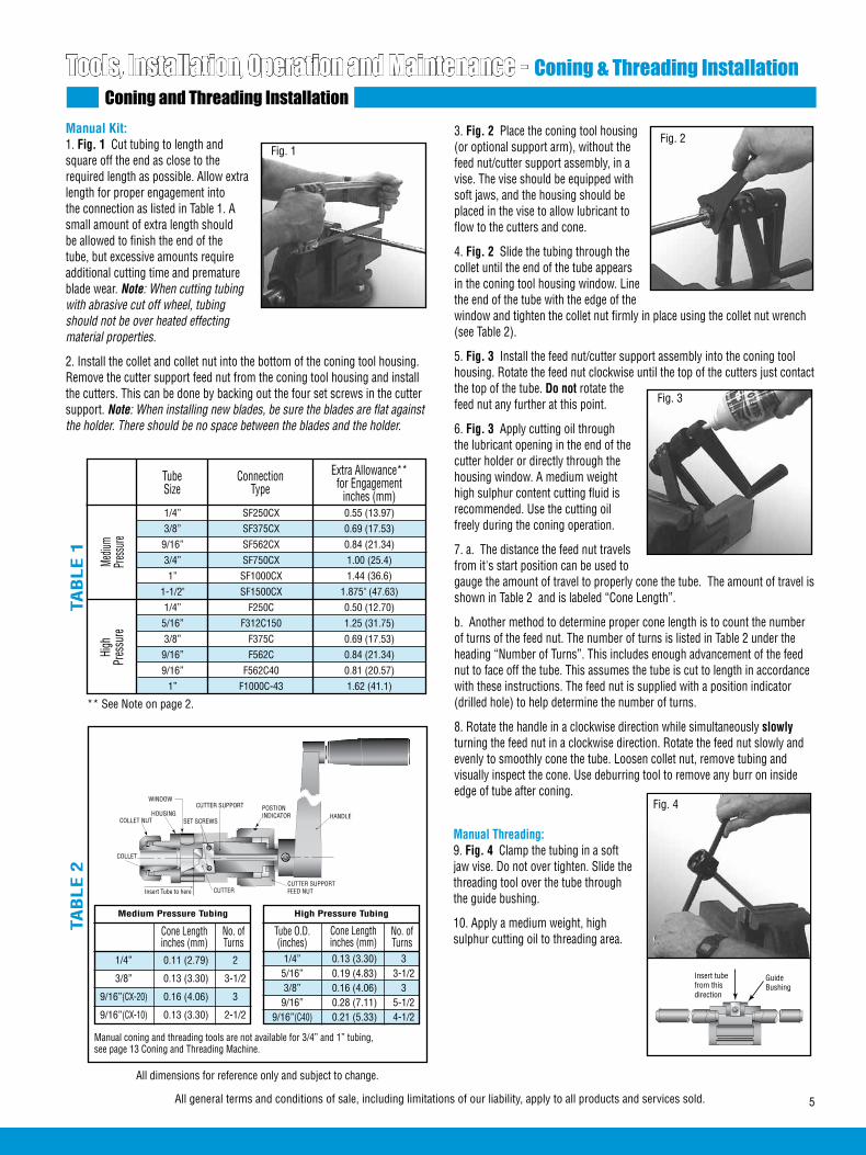
5All general terms and conditions of sale, including limitations of our liability, apply to all products and services sold.
3. Fig. 2 Place the coning tool housing (or optional support arm), without the feed nut/cutter support assembly, in a vise. The vise should be equipped with soft jaws, and the housing should be placed in the vise to allow lubricant to flow to the cutters and cone.
4. Fig. 2 Slide the tubing through the collet until the end of the tube appears in the coning tool housing window. Line the end of the tube with the edge of the window and tighten the collet nut firmly in place using the collet nut wrench (see Table 2).
5. Fig. 3 Install the feed nut/cutter support assembly into the coning tool housing. Rotate the feed nut clockwise until the top of the cutters just contact the top of the tube. Do not rotate the feed nut any further at this point.
6. Fig. 3 Apply cutting oil through the lubricant opening in the end of the cutter holder or directly through the housing window. A medium weight high sulphur content cutting fluid is recommended. Use the cutting oil freely during the coning operation.
7. a. The distance the feed nut travels from it's start position can be used to gauge the amount of travel to properly cone the tube. The amount of travel is shown in Table 2 and is labeled “Cone Length”.
b. Another method to determine proper cone length is to count the number of turns of the feed nut. The number of turns is listed in Table 2 under the heading “Number of Turns”. This includes enough advancement of the feed nut to face off the tube. This assumes the tube is cut to length in accordance with these instructions. The feed nut is supplied with a position indicator (drilled hole) to help determine the number of turns.
8. Rotate the handle in a clockwise direction while simultaneously slowly turning the feed nut in a clockwise direction. Rotate the feed nut slowly and evenly to smoothly cone the tube. Loosen collet nut, remove tubing and visually inspect the cone. Use deburring tool to remove any burr on inside edge of tube after coning.
Manual Kit: 1. Fig. 1 Cut tubing to length and square off the end as close to the required length as possible. Allow extra length for proper engagement into the connection as listed in Table 1. A small amount of extra length should be allowed to finish the end of the tube, but excessive amounts require additional cutting time and premature blade wear. Note: When cutting tubing with abrasive cut off wheel, tubing should not be over heated effecting material properties.
2. Install the collet and collet nut into the bottom of the coning tool housing.Remove the cutter support feed nut from the coning tool housing and install the cutters. This can be done by backing out the four set screws in the cutter support. Note: When installing new blades, be sure the blades are flat against the holder. There should be no space between the blades and the holder.
Tools, Installation, Operation and Maintenance - Coning & Threading InstallationConing and Threading Installation
Cone Lengthinches (mm)
No. ofTurns
Medium Pressure Tubing
Manual coning and threading tools are not available for 3/4” and 1” tubing, see page 13 Coning and Threading Machine.
Tube O.D.(inches)
No. ofTurns
High Pressure Tubing
1/4” SF250CX 0.55 (13.97) 3/8” SF375CX 0.69 (17.53) 9/16” SF562CX 0.84 (21.34) 3/4” SF750CX 1.00 (25.4) 1” SF1000CX 1.44 (36.6) 1-1/2" SF1500CX 1.875" (47.63) 1/4” F250C 0.50 (12.70) 5/16” F312C150 1.25 (31.75) 3/8” F375C 0.69 (17.53) 9/16” F562C 0.84 (21.34) 9/16” F562C40 0.81 (20.57) 1” F1000C-43 1.62 (41.1)
Extra Allowance**for Engagement
inches (mm)TubeSize
ConnectionType
Mediu
mPr
essu
reHi
ghPr
essu
re
TAB
LE 2
TAB
LE 1
All dimensions for reference only and subject to change.
Fig. 1
Fig. 3
Insert tubefrom thisdirection
Guide Bushing
Cone Lengthinches (mm)
** See Note on page 2.
Manual Threading: 9. Fig. 4 Clamp the tubing in a soft jaw vise. Do not over tighten. Slide the threading tool over the tube through the guide bushing.
10. Apply a medium weight, high sulphur cutting oil to threading area.
Fig. 4
Fig. 2
COLLET NUT
COLLET
HOUSINGCUTTER SUPPORT
SET SCREWS
CUTTERCUTTER SUPPORTFEED NUT
HANDLE
WINDOW
Insert Tube to here
POSTION INDICATOR
1/4” 0.11 (2.79) 2
3/8” 0.13 (3.30) 3-1/2
9/16”(CX-20) 0.16 (4.06) 3
9/16”(CX-10) 0.13 (3.30) 2-1/2
1/4” 0.13 (3.30) 3 5/16” 0.19 (4.83) 3-1/2 3/8” 0.16 (4.06) 3 9/16” 0.28 (7.11) 5-1/2 9/16”(C40) 0.21 (5.33) 4-1/2
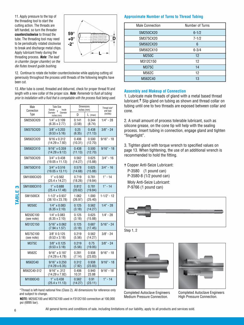
6 All general terms and conditions of sale, including limitations of our liability, apply to all products and services sold.
11. Apply pressure to the top of the threading tool to start the cutting action. The threads are left handed, so turn the threader counterclockwise to thread the tube. The threading tool may need to be periodically rotated clockwise to break and discharge metal chips.Apply lubricant freely during the threading process. Note: The lead in chamfer (larger chamfer) on the die flutes toward guide bushing.
12. Continue to rotate die holder counterclockwise while applying cutting oil generously throughout the process until threads of the following lengths have been cut.
13. After tube is coned, threaded and deburred, check for proper thread fit and length with a new collar of the proper size. Note: Rememebr to flush all tubing prior to installation with a fluid that is compatiable with the process fluid being used.
MaleConnection
Type
TAB
LE 3
Tube Size Outside Inside Diameter Diameter
inches (mm)
X D L (max)
Dimensionsinches (mm)
Thread size*and type(inches)
Assembly and Makeup of Connection1. Lubricate male threads of gland with a metal based thread lubricant.= Slip gland on tubing as shown and thread collar on tubing until one to two threads are exposed between collar and cone.
2. A small amount of process tolerable lubricant, such as silicone grease, on the cone tip will help with the sealing process. Insert tubing in connection, engage gland and tighten “fingertight”.
3. Tighten gland with torque wrench to specified values on page 13. When tightening, the use of an additional wrench is recommended to hold the fitting.
= Copper Anti-Seize Lubricant: P-3580 (1 pound can) P-3580-8 (1/2 pound can)
Moly Anti-Seize Lubricant: P-9766 (1 pound can)
Step 1, 2
Completed Autoclave Engineers Medium Pressure Connection.
Completed Autoclave Engineers High Pressure Connection.
L
D59°+0°-2°
NOTE: M250C100 and M375C100 used in F312C150 connection at 100,000 psi (6895 bar).
SM250CX20 1/4” x 0.109 0.141 0.344 1/4” - 28 (6.35 x 2.77) (3.58) (8.74)
SM375CX20 3/8” x 0.203 0.25 0.438 3/8” - 24 (9.53 x 5.16) (6.35) (11.13)
SM562CX20 9/16 x 0.312 0.406 0.500 9/16” - 18 (14.29 x 7.92) (10.31) (12.70)
SM562CX10 9/16” x 0.359 0.438 0.500 9/16” - 18 (14.29 x 9.12) (11.13) (12.70)
SM750CX20 3/4” x 0.438 0.562 0.625 3/4” - 16 (19.05 x 11.13) (14.27) (15.88)
SM750CX10 3/4” x 0.516 0.578 0.625 3/4” - 16 (19.05 x 13.11) (14.68) (15.88)
SM1000CX20 1” x 0.562 0.719 0.781 1” - 14 (25.4 x 14.27) (18.26) (19.84)
SM1000CX10 1” x 0.688 0.812 0.781 1” - 14 (25.4 x 17.48) (20.62) (19.84)
SM1500CX 1-1/2" x 0.937 1.062 1.000 1-1/2" - 12 (38.10 x 23.78) (26.97) (25.40)
M250C 1/4” x 0.083 0.125 0.562 1/4” - 28 (6.35 x 2.10) (3.18) (14.27)
M250C100 1/4" x 0.083 0.125 0.625 1/4" - 28 (see note) (6.35 x 2.10) (3.18) (15.88)
M312C150 5/16” x 0.062 0.125 0.687 5/16” - 24 (7.94 x 1.57) (3.18) (17.45)
M375C100 3/8" X 0.125 0.219 0.562 3/8" - 24 (see note) (9.53 x 3.18) (5.56) (14.27)
M375C 3/8” x 0.125 0.219 0.75 3/8” - 24 (9.53 x 3.18) (5.56) (19.05)
M562C 9/16” x 0.187 0.281 0.938 9/16” - 18 (14.29 x 4.78) (7.14) (23.83)
M562C40 9/16” x 0.250 0.312 0.938 9/16” - 18 (14.29 x 6.35) (7.92) (23.83) M562C40-312 9/16” x .312 0.406 0.940 9/16" - 18 (14.29 x 7.92) 10.31 23.88 M1000C43 1” x 0.438 0.562 0.91 1” - 14 (25.4 x 11.13) (14.27) (23.11)
*Thread is left-hand national fine (Class 2). All dimensions for reference only and subject to change.
Approximate Number of Turns to Thread Tubing
Male Connection Number of Turns
SM250CX20 6-1/2
SM375CX20 7-1/2
SM562CX20 6
SM562CX10 6-3/4
M250C 12
M312C150 12
M375C 14
M562C 12
M562C40 13

7All general terms and conditions of sale, including limitations of our liability, apply to all products and services sold.
1. Cut tubing to length and deburr. Allow extra length for proper engagement (per table below).
2. Slip gland and sleeve onto tubing.
Note: Be sure to remove gland and sleeve from components and slide them onto the tubing before inserting the tubing into the components.
Make sure larger end of sleeve is toward gland.
Push tubing into valve or fitting until it bottoms. Lubricate gland nut threads to aid in assembly. If process tolerable, a slight amount of inert grease on the nose of the compression sleeve is recommended to improve sealability.
3. TIGHTEN GLAND NUT UNTIL SLEEVE BEGINS TO GRIP TUBING.
4. Note starting position of wrench.† Tighten gland nut 1-1/4 turns to complete the QSS connection.*
Outside Diameter Extra Allowance** Tube Size for Engagement inches (mm) inches (mm)
1/4 (6.35) 0.75 (19.05)
3/8 (9.53) 0.81 (20.64)
Tools, Installation, Operation and Maintenance - QSS Assembly ProcedureQSS Assembly Procedure
Step 1 Step 2
Step 3 Step 4
Completed Connection
The illustration below shows the condition of sleeve and tub-ing after completion of “sleeve setting.” The sleeve has cut into the tubing as it moved forward into the tapered seat, up-setting material ahead of it and establishing a shoulder on the tubing to provide positive mechanical support for the tubing end-load. A properly set sleeve cannot be displaced back and forth along the tubing but may be rotated around the tubing.
Larger end of sleeve toward gland
Gland
Fitting
See Note **
Bite into tubing exaggerated for clarity
Reassembly
To reassemble a 1/4 or 3/8 connection, insert tubing with sleeve and gland nut into valve or fitting. Tighten gland nut until the sleeve begins to grip tubing. Tighten gland with a wrench 1/4 of a turn for a gas-tight seal. After frequent reas-semblies, it may take less than 1/4 turn to affect a gas-tight seal and as little as 1/8 of a turn may be sufficient.
Fast, Positive Sealing for Pressures up to 15,000 psi (1034 bar)1/4” & 3/8” Tubing Size (Standard setting operation)See next page for setting with hydraulic tool.(Setting with hydraulic tool is recommended but not required).
Torque values can be used for both initial setting and reas-sembly connections. See the following page for reassembly values and ranges. Initial setting torque ft-lbs (NM) 1/4” 40 (54.3) 3/8” 80 (108.5)
* No special torque wrenches or mandrels required.
** Distance tubing protrudes into connection from face of fitting.† A small blind hole on the face of the gland is provided for a starting position reference.
Parker Autoclave Engineers Medium Pressure tubing is r equired for these connection components.
When assembling tubing into fittings such as in rack systems, alignment of tubing is critical in connection make up.Do not force tubing into alignment with connections as bend-ing stress will effect the sealing capability of the connections.

8 All general terms and conditions of sale, including limitations of our liability, apply to all products and services sold.
Tools, Installation, Operation and Maintenance - QSS Assembly ProcedureQSS Assembly Procedure
1. Cut tubing to length and deburr. Allow extra length for proper engagement (per table below).
2. Slip gland nut and sleeve onto tubing. Lubricate the nose of the compression sleeve or the tapered die surface with a metal to metal lubricant. We recommend Jetlube MP-50. Make sure larger end of sleeve is toward gland nut. Push tubing into hydraulic set tool until it bottoms into the setting die. For the 1" size only, as-semble the split nut (2A-1) around the tubing between the sleeve and gland with the larger counter bore towards the gland and thread into the cap. Be sure both the split nut and cap have been tightened down and neither can be moved by hand. The cap should always be flush with the top of the housing (2A-2) whilethe split nut will not. Skip step 3.
Fast, Positive Sealing for Pressures up to 15,000 psi (1034 bar)Hydraulic Set Tool Assembly
3. Thread gland nut into cap until the hex touches the top surface.4. Pressurize cylinder up to the set pressure (per table below.)DO NOT EXCEED THE SET PRESSURE.AS WITH ALL HIGH PRESSURE EQUIPMENT, USE CAUTIONDURING OPERATION. SET TOOL MAWP IS 10,000 PSI (690 BAR).
Vent all presssure from hydraulic cylinder. Remove gland assembly from preset tool and inspect biting end of sleeve. Looking inside the biting end of the sleeve you should see a shoulder pushed up from the tubing material. A properly set sleeve must spin freely to achieve a seal. If the sleeve is seized in place after setting, discard and make another. Do not set a sleeve more than once.5. Install gland assembly into valve/fitting. If process tolerable, a slight amount of inert grease on the nose of the compression sleeve should be used to aid sealing. Lubrication of gland threadswill also aid in assembly.TIGHTEN GLAND NUT UNTIL SLEEVE BEGINS TO GRIP TUBING.6. Note starting position of wrench.† Tighten gland nut 1/4 turn to complete the QSS connection. Since the mechanical bite has already been completed with the hydraulic set tool, it is permis-sible to vary the torque to achieve sealing.
Completed ConnectionThe hydraulically set sleeve has cut into the tubing as it moved forward into the tapered seat, upsetting material ahead of it and establishing a shoulder on the tubing to provide positive mechan-ical support for the tubing end-load. A properly set sleeve cannot be displaced back and forth along the tubing but may be rotated around the tubing.ReassemblyTo reassemble a connection, insert tubing with sleeve and gland nut into valve or fitting. Install gland into valve/fitting.TIGHTEN GLAND NUT UNTIL SLEEVE BEGINS TO GRIP TUBING.Note starting position of wrench.† Tighten gland nut 1/4 turn to complete the QSS connection. ** Distance tubing protrudes into connection from face of fitting.† A small blind hole on the face of the gland is provided for a start-ing position reference.Parker Autoclave Engineers Medium Pressure tubing is required for these connection components.
Outside Diameter Tube Size Extra Allowance for Engagement** inches (mm) inches (mm)
1/4 (6.35) 0.75 (19.05) 3/8 (9.53) 0.81 (20.64) 9/16 (14.27) 1.25 (31.75) 3/4 (19.04) 1.63 (41.28) 1 (25.40) 1.75 (44.45)
Outside Diameter Tube Size Set Pressure for Full Tubing Bite inches (mm) psi (bar)
1/4 (6.35) 3/8 (9.53) 9/16 (14.27) 4500 (310) to 5000 (344) 3/4 (19.04) 8000 (552) to 10000 (690) 1 (25.4) 9000 (620) to 9500 (655)
When assembling tubing into fittings such as in rack systems, alignment of tubing is critical in connection make up. Do not force into alignment with connections as bending stress will effect the sealing capability of the connections.
Step 1 Step 2
Step 5 Step 6
Step 3 Step 4
Step 2A-1 Step 2A-2
If torque values are required, use the following: Size Required Torque Max. Torque Torque Wrench Adapter (in) ft-lbs (Nm) ft-lbs (Nm) Adapter Size Part # 1/4” 30 (40.7) 50 (67.8) 5/8” P-1683 3/8” 35 (47.5) 75 (101.6) 3/4” P-9813 9/16” 90 (122.0) 135 (183.0) 1-3/16” P-1689 3/4” 175 (237.3) 250 (339.0) 1-1/2” P-6040 1” 375 (508.4) 500 (677.9) 1-3/4” 91269

9All general terms and conditions of sale, including limitations of our liability, apply to all products and services sold.
Tools, Installation, Operation and Maintenance - Hydraulic Sleeve Set ToolHydraulic Sleeve Set Tool
The Parker Autoclave Engineers hydraulic sleeve set tool is designed for use with the QS Series glands, sleeves and Autoclave tubing. This tool is required to set the sleeve for the 9/16” and 3/4” sizes and suggested for the 1/4” and 3/8” sizes. It not only produces the required bite into the tubing, it is much easier than trying to set the sleeve the conventional method. The tool comes in a self contained portable, lockable case complete with hand or air pump, cap and dies for all sizes.
Cap
Die
Housing
HydraulicCylinder
Base
Hose Connection3/8” NPT
Tooling Installation and Changing SizesTo change tooling to another size only requires interchanging 2 parts.1. Loosen the 5/16" set screw that locks the threaded cap from rotating.2. Using a 5/32" hex key to rotate and remove the threaded steel cap from the aluminum housing.3. Turn the tool assembly upside down to remove the die from inside the housing.4. Install the die of the appropriate connection size you wish to use. The solid side of the die should be facing down towards the hydraulic cylinder.5. Install the appropriate size cap to match the size of the die. Insert cap with the 5/32" hex up. Rotate with a 5/32" hex key until it bottoms out on the shoulder side of the housing.6. Thread in the 5/16" set screw until it bottoms out on the cap threads. Tighten set screw to prevent movement during use.
Ordering InformationHST-912: Complete tool kit with hand pump (shown in photo) HST-912TW: Complete tool kit with torque wrench and adapters HST-912A: Complete tool kit with air-operated pump (Airoperated pump #P-1948)HST-912ATW: Complete tool kit with torque wrench and adapters HST-S: Complete table mounted system that includes everything in the HST-912ATW plus the required tooling for the 1" size connections.Not shown. Consult factory for replacement parts.
Description Part #
Hydraulic Cylinder 90588 Gauge 90594 Adapter 90593 Base 101F-3407 Housing 101F-3408 Hydraulic Pump P-1893 Hose P-1894 3/4” Die HSTD12 9/16” Die HSTD9 3/4” Cap HSTC12 9/16” Cap HSTC9 Tool Chest P-10011 Moly Paste P-9766
20 to 150 ft-lbs (27-203 Nm) Torque Wrench P-168075 to 250 ft-lbs (102-339 Nm) Torque Wrench 910205/8” wrench adapter P-16833/4” wrench adapter P-98131-3/16” wrench adapter P-16891-1/2” wrench adapter P-6040
1/4” Die HSTD4 1/4” Cap HSTC4 3/8” Die HSTD6 3/8” Cap HSTC6 (TW) Kits with torque and adapters
FeaturesCase Dimensions: 28”W x 14.25”H x 13.75”D (711cm x 362cm x 292cm)Total Weight: 69 lbs. (31 Kg)Hand Pump: Single stage hydraulic (standard)Hydraulic Cylinder: 10,000 psi, 2.5” 25 tonBase & Housing: Aluminum anodizedDie and Cap: Precision hardened steelGauge: 15,000 psi (1034 bar)Air-operated hydraulic pump option can be furnished in place of standard hand pump. (Add “-A” to order number). Operating pressure 0 to 10,000 psi (0 to 690 bar). Required air presssure, 30 psi (2.1 bar) minimum 120 psi (8.3 bar) maximum. Reservoir capacity: 24 cu. in. (393cm3). Air lubricator/air separator is recommended for air operated units.
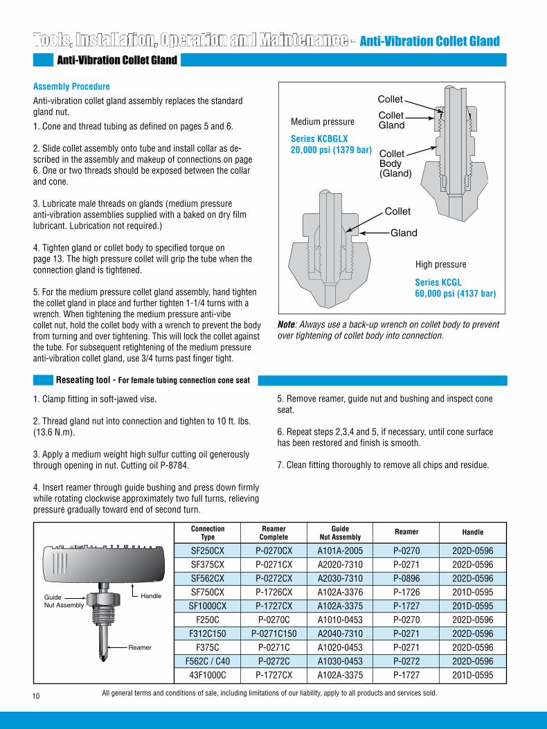
10 All general terms and conditions of sale, including limitations of our liability, apply to all products and services sold.
Tools, Installation, Operation and Maintenance - Anti-Vibration Collet GlandAnti-Vibration Collet Gland
Assembly Procedure
Anti-vibration collet gland assembly replaces the standard gland nut.
1. Cone and thread tubing as defined on pages 5 and 6.
2. Slide collet assembly onto tube and install collar as de-scribed in the assembly and makeup of connections on page 6. One or two threads should be exposed between the collar and cone.
3. Lubricate male threads on glands (medium pressure anti-vibration assemblies supplied with a baked on dry film lubricant. Lubrication not required.)
4. Tighten gland or collet body to specified torque on page 13. The high pressure collet will grip the tube when the connection gland is tightened.
5. For the medium pressure collet gland assembly, hand tighten the collet gland in place and further tighten 1-1/4 turns with a wrench. When tightening the medium pressure anti-vibecollet nut, hold the collet body with a wrench to prevent the body from turning and over tightening. This will lock the collet against the tube. For subsequent retightening of the medium pressure anti-vibration collet gland, use 3/4 turns past finger tight.
SF250CX P-0270CX A101A-2005 P-0270 202D-0596 SF375CX P-0271CX A2020-7310 P-0271 202D-0596 SF562CX P-0272CX A2030-7310 P-0896 202D-0596 SF750CX P-1726CX A102A-3376 P-1726 201D-0595 SF1000CX P-1727CX A102A-3375 P-1727 201D-0595 F250C P-0270C A1010-0453 P-0270 202D-0596 F312C150 P-0271C150 A2040-7310 P-0271 202D-0596 F375C P-0271C A1020-0453 P-0271 202D-0596 F562C / C40 P-0272C A1030-0453 P-0272 202D-0596 43F1000C P-1727CX A102A-3375 P-1727 201D-0595
ConnectionType
ReamerComplete
GuideNut Assembly
Reamer Handle
5. Remove reamer, guide nut and bushing and inspect cone seat.
6. Repeat steps 2,3,4 and 5, if necessary, until cone surface has been restored and finish is smooth.
7. Clean fitting thoroughly to remove all chips and residue.
1. Clamp fitting in soft-jawed vise.
2. Thread gland nut into connection and tighten to 10 ft. lbs. (13.6 N.m).
3. Apply a medium weight high sulfur cutting oil generously through opening in nut. Cutting oil P-8784.
4. Insert reamer through guide bushing and press down firmly while rotating clockwise approximately two full turns, relieving pressure gradually toward end of second turn.
Series KCBGLX20,000 psi (1379 bar)
Series KCGL60,000 psi (4137 bar)
Medium pressure
High pressure
Reseating tool - For female tubing connection cone seat
GuideNut Assembly
Reamer
Handle
Note: Always use a back-up wrench on collet body to prevent over tightening of collet body into connection.
Collet
ColletGland
ColletBody(Gland)
Collet
Gland
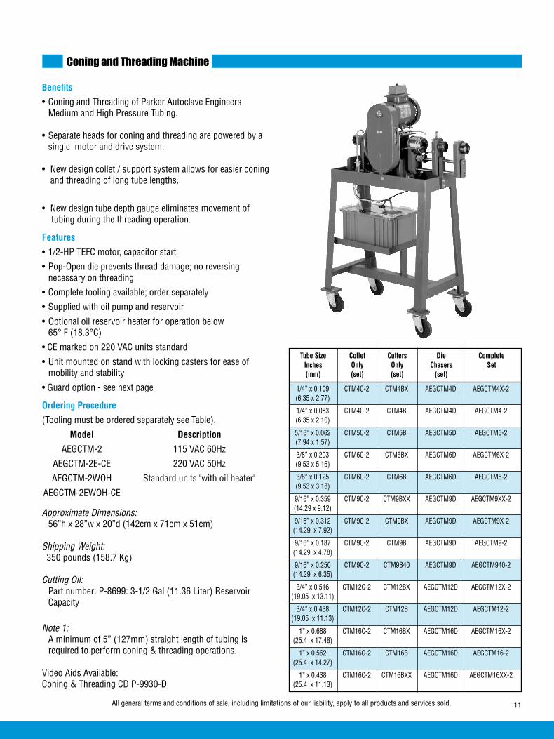
11All general terms and conditions of sale, including limitations of our liability, apply to all products and services sold.
Coning and Threading Machine
Benefits
• Coning and Threading of Parker Autoclave Engineers Medium and High Pressure Tubing. • Separate heads for coning and threading are powered by a single motor and drive system. • New design collet / support system allows for easier coning and threading of long tube lengths.
• New design tube depth gauge eliminates movement of tubing during the threading operation.
Features
• 1/2-HP TEFC motor, capacitor start
• Pop-Open die prevents thread damage; no reversing necessary on threading
• Complete tooling available; order separately
• Supplied with oil pump and reservoir
• Optional oil reservoir heater for operation below 65° F (18.3°C)
• CE marked on 220 VAC units standard
• Unit mounted on stand with locking casters for ease of mobility and stability
• Guard option - see next page
Ordering Procedure
(Tooling must be ordered separately see Table).
Model Description
AEGCTM-2 115 VAC 60Hz
AEGCTM-2E-CE 220 VAC 50Hz
AEGCTM-2WOH Standard units "with oil heater"
AEGCTM-2EWOH-CE
Approximate Dimensions: 56”h x 28”w x 20”d (142cm x 71cm x 51cm)
Shipping Weight: 350 pounds (158.7 Kg)
Cutting Oil: Part number: P-8699: 3-1/2 Gal (11.36 Liter) Reservoir Capacity
Note 1: A minimum of 5” (127mm) straight length of tubing is required to perform coning & threading operations.
Video Aids Available:Coning & Threading CD P-9930-D
1/4” x 0.109 CTM4C-2 CTM4BX AEGCTM4D AEGCTM4X-2 (6.35 x 2.77)
1/4” x 0.083 CTM4C-2 CTM4B AEGCTM4D AEGCTM4-2 (6.35 x 2.10)
5/16” x 0.062 CTM5C-2 CTM5B AEGCTM5D AEGCTM5-2 (7.94 x 1.57)
3/8” x 0.203 CTM6C-2 CTM6BX AEGCTM6D AEGCTM6X-2 (9.53 x 5.16)
3/8” x 0.125 CTM6C-2 CTM6B AEGCTM6D AEGCTM6-2 (9.53 x 3.18)
9/16” x 0.359 CTM9C-2 CTM9BXX AEGCTM9D AEGCTM9XX-2 (14.29 x 9.12)
9/16” x 0.312 CTM9C-2 CTM9BX AEGCTM9D AEGCTM9X-2 (14.29 x 7.92)
9/16” x 0.187 CTM9C-2 CTM9B AEGCTM9D AEGCTM9-2 (14.29 x 4.78)
9/16” x 0.250 CTM9C-2 CTM9B40 AEGCTM9D AEGCTM940-2 (14.29 x 6.35)
3/4” x 0.516 CTM12C-2 CTM12BX AEGCTM12D AEGCTM12X-2 (19.05 x 13.11)
3/4” x 0.438 CTM12C-2 CTM12B AEGCTM12D AEGCTM12-2 (19.05 x 11.13)
1” x 0.688 CTM16C-2 CTM16BX AEGCTM16D AEGCTM16X-2 (25.4 x 17.48)
1” x 0.562 CTM16C-2 CTM16B AEGCTM16D AEGCTM16-2 (25.4 x 14.27)
1” x 0.438 CTM16C-2 CTM16BXX AEGCTM16D AEGCTM16XX-2 (25.4 x 11.13)
Tube Size Collet Cutters Die Complete Inches Only Only Chasers Set (mm) (set) (set) (set)

12 All general terms and conditions of sale, including limitations of our liability, apply to all products and services sold.
Coning and Threading Machine
Note: Detailed operational instructions are supplied with the machine in two forms, printed and DVD. Refer to these instruc-tions for tooling installation, machine adjustment, and maintenance instructions.
Optional Oil/Chip Guard
A threading die oil/chip guard is available as an option on our AEGCTM machines.
The guard is a swing away Plexiglas design providing protection from splashing oil or thrown chips while allowing full access to the die head. The guard’s sole purpose is the prevention of flying chips and oil not the prevention of operator access. A guard option will also be available in a retrofit kit for our new existing machines (-2 models). The kit will contain all required items along with instructions.
To order a guard with a model, just add a G to the catalog number. AEGCTM-2G AEGCTM-2E-CEGAEGCTM-2GK Retrofit kit catalog number
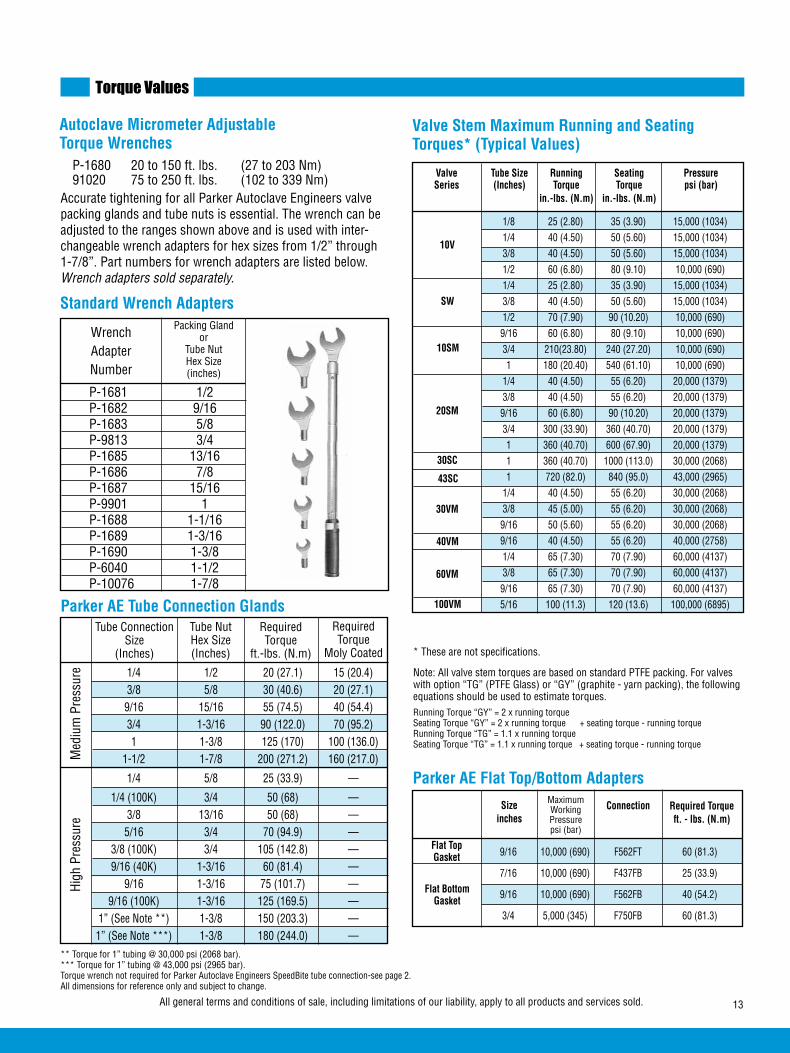
13All general terms and conditions of sale, including limitations of our liability, apply to all products and services sold.
Torque Values
Autoclave Micrometer Adjustable Torque Wrenches
WrenchAdapterNumber
Packing Gland or
Tube Nut Hex Size(inches)
Note: All valve stem torques are based on standard PTFE packing. For valves with option “TG” (PTFE Glass) or “GY” (graphite - yarn packing), the following equations should be used to estimate torques.Running Torque “GY” = 2 x running torqueSeating Torque “GY” = 2 x running torque + seating torque - running torqueRunning Torque “TG” = 1.1 x running torqueSeating Torque “TG” = 1.1 x running torque + seating torque - running torque
1/8 25 (2.80) 35 (3.90) 15,000 (1034) 1/4 40 (4.50) 50 (5.60) 15,000 (1034) 3/8 40 (4.50) 50 (5.60) 15,000 (1034) 1/2 60 (6.80) 80 (9.10) 10,000 (690) 1/4 25 (2.80) 35 (3.90) 15,000 (1034) 3/8 40 (4.50) 50 (5.60) 15,000 (1034) 1/2 70 (7.90) 90 (10.20) 10,000 (690) 9/16 60 (6.80) 80 (9.10) 10,000 (690) 3/4 210(23.80) 240 (27.20) 10,000 (690) 1 180 (20.40) 540 (61.10) 10,000 (690) 1/4 40 (4.50) 55 (6.20) 20,000 (1379) 3/8 40 (4.50) 55 (6.20) 20,000 (1379) 9/16 60 (6.80) 90 (10.20) 20,000 (1379) 3/4 300 (33.90) 360 (40.70) 20,000 (1379) 1 360 (40.70) 600 (67.90) 20,000 (1379) 1 360 (40.70) 1000 (113.0) 30,000 (2068) 1 720 (82.0) 840 (95.0) 43,000 (2965) 1/4 40 (4.50) 55 (6.20) 30,000 (2068) 3/8 45 (5.00) 55 (6.20) 30,000 (2068) 9/16 50 (5.60) 55 (6.20) 30,000 (2068) 9/16 40 (4.50) 55 (6.20) 40,000 (2758) 1/4 65 (7.30) 70 (7.90) 60,000 (4137) 3/8 65 (7.30) 70 (7.90) 60,000 (4137) 9/16 65 (7.30) 70 (7.90) 60,000 (4137) 5/16 100 (11.3) 120 (13.6) 100,000 (6895)
Valve Tube Size Running Seating Pressure Series (Inches) Torque Torque psi (bar) in.-lbs. (N.m) in.-lbs. (N.m)
Valve Stem Maximum Running and Seating Torques* (Typical Values)
10V
SW
20SM
30SC
30VM
40VM
60VM
100VM
9/16 10,000 (690) F562FT 60 (81.3)
7/16 10,000 (690) F437FB 25 (33.9)
9/16 10,000 (690) F562FB 40 (54.2)
3/4 5,000 (345) F750FB 60 (81.3)
Parker AE Flat Top/Bottom Adapters
Flat TopGasket
Flat BottomGasket
Maximum Working Pressure psi (bar)
Sizeinches
Connection Required Torqueft. - lbs. (N.m)
10SM
Standard Wrench Adapters
P-1681 1/2 P-1682 9/16 P-1683 5/8 P-9813 3/4 P-1685 13/16 P-1686 7/8 P-1687 15/16 P-9901 1 P-1688 1-1/16 P-1689 1-3/16 P-1690 1-3/8 P-6040 1-1/2 P-10076 1-7/8
* These are not specifications.
P-1680 20 to 150 ft. lbs. (27 to 203 Nm)91020 75 to 250 ft. lbs. (102 to 339 Nm)
Accurate tightening for all Parker Autoclave Engineers valve packing glands and tube nuts is essential. The wrench can be adjusted to the ranges shown above and is used with inter-changeable wrench adapters for hex sizes from 1/2” through 1-7/8”. Part numbers for wrench adapters are listed below. Wrench adapters sold separately.
Parker AE Tube Connection GlandsTube Connection
Size (Inches)
Tube NutHex Size(Inches)
RequiredTorque
ft.-lbs. (N.m)
High
Pre
ssur
eM
ediu
m P
ress
ure
** Torque for 1” tubing @ 30,000 psi (2068 bar).*** Torque for 1” tubing @ 43,000 psi (2965 bar).Torque wrench not required for Parker Autoclave Engineers SpeedBite tube connection-see page 2. All dimensions for reference only and subject to change.
1/4 1/2 20 (27.1) 15 (20.4) 3/8 5/8 30 (40.6) 20 (27.1) 9/16 15/16 55 (74.5) 40 (54.4) 3/4 1-3/16 90 (122.0) 70 (95.2) 1 1-3/8 125 (170) 100 (136.0) 1-1/2 1-7/8 200 (271.2) 160 (217.0)
1/4 5/8 25 (33.9) —
1/4 (100K) 3/4 50 (68) — 3/8 13/16 50 (68) — 5/16 3/4 70 (94.9) — 3/8 (100K) 3/4 105 (142.8) — 9/16 (40K) 1-3/16 60 (81.4) — 9/16 1-3/16 75 (101.7) — 9/16 (100K) 1-3/16 125 (169.5) — 1” (See Note **) 1-3/8 150 (203.3) — 1” (See Note ***) 1-3/8 180 (244.0) —
RequiredTorque
Moly Coated
43SC

14 All general terms and conditions of sale, including limitations of our liability, apply to all products and services sold.
1/8 1/2 12 (16.3) 1/4 13/16 40 (54.2) 3/8 13/16 40 (54.2) 1/2 13/16 30 (40.7) 1/4 5/8 30 (40.7) 3/8 5/8 4 (54.2) 1/2 13/16 50 (67.8) 1/4 5/8 40 (54.2) 3/8 5/8 40 (54.2) 9/16 13/16 80 (108.5) 3/4 13/16 Note: 2
1 1-3/8 20 (27.1) 1 1-3/8 230 (311.8) 1/4 13/16 60 (81.3) 3/8 13/16 60 (81.3) 9/16 13/16 60 (81.3)
Parker AE Packing Glands
10V
Packing Gland Hex (Inches)
Outside Diameter
Size (inches)
Required Torque1
ft.-lbs. (N.m)
1 - Torque may vary ±10%. Torque values apply to standard PTFE packing. For graphite yarn packing, add 25% to tthe above values.
2 - 3/4 turn past finger tight with hex wrench.
Torque Values
Valve Series
SW
10SM&
20SM
30SC
30VM
9/16 13/16 40 (54.2) 1/4 13/16 60 (81.3) 3/8 13/16 60 (81.3) 9/16 13/16 60 (81.3) 5/16 15/16 60 (81.3) 5/16 1-3/8 150 (203.3) 3/4 15/16 130 (176.3) 1 1-1/16 150 (203.3) 9/16 15/16 85 (115.2) 9/16 9/16 20 (27.1) 3/4 13/16 50 (67.8) 1/4 13/16 50 (67.8) 3/8 13/16 50 (67.8)
Parker AE Packing Glands
40VM
Packing Gland Hex (Inches)
Outside Diameter
Size (Inches)
Required Torque1
ft.-lbs. (N.m)Valve Series
150V
10VRMM
60VRMM
60VM
100VM
15Y
50Y
30VRMM
10 (13.6) 10 (13.6) 10 (13.6) 10 (13.6) 15 (20.3) 20 (27.1) — — — — —
10 (13.6) 10 (13.6) 10 (13.6) 15 (20.3) 25 (33.9) 30 (40.7) — — — — —
20 (27.1) 20 (27.1) 30 (40.7) 55 (74.6) — — — — — — —
15 (20.3) 15 (20.3) 15 (20.3) 30 (40.7) 40 (54.2) 55 (74.6) — — — — —
25 (33.9) 25 (33.9) 40 (54.2) 75 (101.7) — — — — — — —
20 (27.1) 20 (27.1) 25 (33.9) 45 (61.0) 70 (94.9) 90 (122.0) — — — — —
40 (54.2) 40 (54.2) 65 (88.1) 125 (169.5) — — — — — — —
35 (47.5) 35 (47.5) 50 (67.8) 100 (135.6) 115 (156.0) 125 (169.5) — — — — —
30 (40.7) 30 (40.7) 50 (67.8) 65 (88.1) 75 (101.7) 100 (135.6) 125 (169.5) 150 (203.3) 180 (244.0) — —
10 (13.6) 10 (13.6) 10 (13.6) 10 (13.6) 10 (13.6) 10 (13.6) 15 (20.3) 15 (20.3) 20 (27.1) 25 (33.9) 25 (33.9)
10 (13.6) 10 (13.6) 10 (13.6) 10 (13.6) 15 (20.3) 20 (27.1) 25 (33.9) 25 (33.9) 35 (47.5) 45 (61.0) 50 (67.8)
15 (20.3) 15 (20.3) 15 (20.3) 15 (20.3) 20 (27.1) 25 (33.9) 35 (47.5) 40 (54.2) 50 (67.86) 65 (88.1) 75 (101.7)
15 (20.3) 15 (20.3) 15 (20.3) 15 (20.3) 25 (33.9) 30 (40.7) 40 (54.2) 45 (61.0) 60 (81.3) — —
Special Material Connection Torque Table Pressure psi (bar) vs. Torque ft.-lbs. (N.m)
SF250CX
ConnectionMinumum 2,500 (172) 5,000 (345) 10,000 (690) 15,000 (1034) 20,000 (1379) 25,000 (1724) 30,000 (2068) 40,000 (2758) 50,000 (3447) 60,000 (4137)
SF375CX
SF562CX10
SF562CX20
SF750CX10
SF750CX20
SF1000CX10
SF1000CX20
F1000C43
F250C
F375C
F562C
F562C40
Pressure psi (bar)
Note: Use the recommended torque value for special material valves and fittings based on the maximum allowable working pressure of the valve or fitting
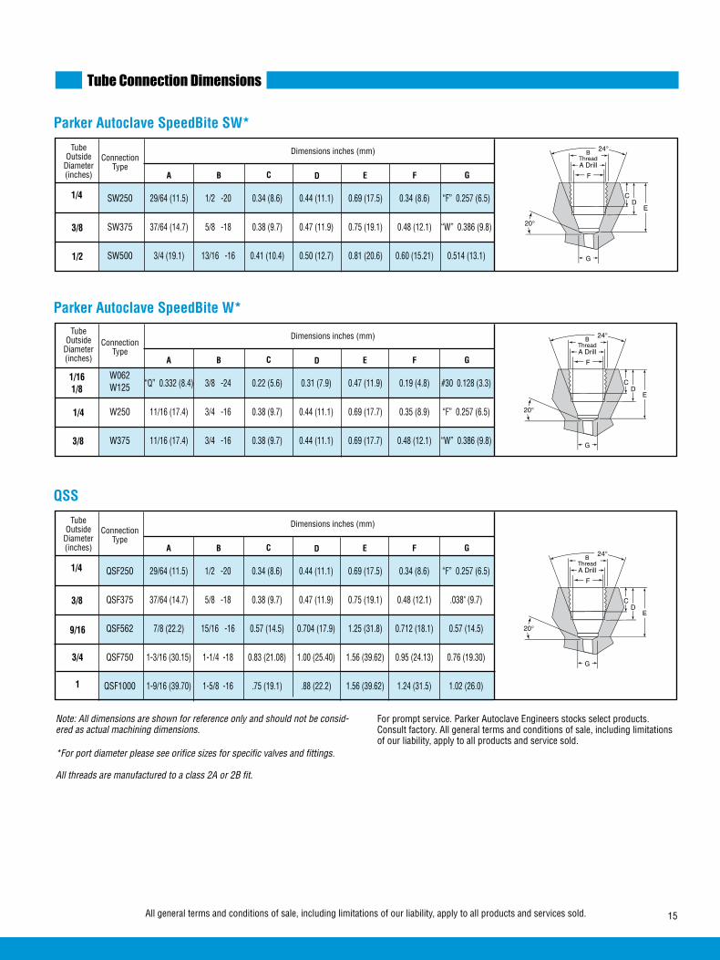
15All general terms and conditions of sale, including limitations of our liability, apply to all products and services sold.
“Q” 0.332 (8.4) 3/8 -24 0.22 (5.6) 0.31 (7.9) 0.47 (11.9) 0.19 (4.8) #30 0.128 (3.3)
W250 11/16 (17.4) 3/4 -16 0.38 (9.7) 0.44 (11.1) 0.69 (17.7) 0.35 (8.9) “F” 0.257 (6.5)
W375 11/16 (17.4) 3/4 -16 0.38 (9.7) 0.44 (11.1) 0.69 (17.7) 0.48 (12.1) “W” 0.386 (9.8)
Parker Autoclave SpeedBite W*
1/161/8
ConnectionType
Tube Outside
Diameter(inches)
3/8
A C D E G
Dimensions inches (mm)
1/4
B F
Tube Connection Dimensions
Note: All dimensions are shown for reference only and should not be consid-ered as actual machining dimensions.
*For port diameter please see orifice sizes for specific valves and fittings.
All threads are manufactured to a class 2A or 2B fit.
For prompt service. Parker Autoclave Engineers stocks select products. Consult factory. All general terms and conditions of sale, including limitations of our liability, apply to all products and service sold.
W062W125
G
ED
C
FA Drill
BThread
SW250 29/64 (11.5) 1/2 -20 0.34 (8.6) 0.44 (11.1) 0.69 (17.5) 0.34 (8.6) “F” 0.257 (6.5)
SW375 37/64 (14.7) 5/8 -18 0.38 (9.7) 0.47 (11.9) 0.75 (19.1) 0.48 (12.1) “W” 0.386 (9.8)
SW500 3/4 (19.1) 13/16 -16 0.41 (10.4) 0.50 (12.7) 0.81 (20.6) 0.60 (15.21) 0.514 (13.1)
Parker Autoclave SpeedBite SW*
1/4
ConnectionType
Tube Outside
Diameter(inches) A C D E G
Dimensions inches (mm)
3/8
B F
1/2
G
ED
C
FA Drill
BThread
QSF250 29/64 (11.5) 1/2 -20 0.34 (8.6) 0.44 (11.1) 0.69 (17.5) 0.34 (8.6) “F” 0.257 (6.5)
QSF375 37/64 (14.7) 5/8 -18 0.38 (9.7) 0.47 (11.9) 0.75 (19.1) 0.48 (12.1) .038" (9.7)
QSF562 7/8 (22.2) 15/16 -16 0.57 (14.5) 0.704 (17.9) 1.25 (31.8) 0.712 (18.1) 0.57 (14.5)
QSF750 1-3/16 (30.15) 1-1/4 -18 0.83 (21.08) 1.00 (25.40) 1.56 (39.62) 0.95 (24.13) 0.76 (19.30)
QSF1000 1-9/16 (39.70) 1-5/8 -16 .75 (19.1) .88 (22.2) 1.56 (39.62) 1.24 (31.5) 1.02 (26.0)
QSS
1/4
ConnectionType
Tube Outside
Diameter(inches) A C D E G
Dimensions inches (mm)
3/8
B F
G
ED
C
FA Drill
BThread
9/16
3/4
1

16 All general terms and conditions of sale, including limitations of our liability, apply to all products and services sold.
Tube Connection Dimensions
Note: All dimensions are shown for reference only and should not be consid-ered as actual machining dimensions.
*For port diameter please see orifice sizes for specific valves and fittings.
**For male tubing end preparation, please see pages 5 and 6. All threads are manufactured to a class 2A or 2B fit.
SF250CX20 25/64 (9.9) 7/16 -20 0.28 (7.1) 0.50 (12.7) 0.19 (4.8) 0.109 (2.8)
SF375CX20 33/64 (13.1) 9/16 -18 0.38 (9.7) 0.62 (15.7) 0.31 (7.9) 0.203 (5.2)
3/4 (19.1) 13/16 -16 0.44 (11.1) 0.75 (19.1) 0.50 (12.7)
61/64 (24.2) 3/4 -14z 0.50 (12.7) 0.94 (23.9) 0.62 (15.7)
1-19/64 (32.9) 1-3/8 -12 0.81 (20.6) 1.31 (33.3) 0.88 (22.4)
SF1500CX 1.790 (45.47) 1-7/8 -12 1.00 (25.4) 1.594 (40.49) 1.375 (34.93) .937 (23.80)
Parker Autoclave Medium Pressure SFCX **
1/4
ConnectionType
Tube Outside(inches)
3/8
9/16
3/4
A B C D F H
Dimensions inches (mm)
1
1
F250C 33/64 (13.1) 9/16 -18 0.38 (9.7) 0.44 (11.1) 0.17 (4.3) 0.094 (2.4)
F375C 11/16 (17.4) 3/4 -16 0.53 (13.5) 0.62 (15.7) 0.26 (6.6) 0.125 (3.2)
F562C 1-3/64 (26.6) 1-1/8 -12 0.62 (15.7) 0.75 (19.1) 0.38 (9.7) 0.188 (4.8)
F562C40 1-3/64 (26.6) 1-1/8 -12 0.62 (15.7) 0.75 (19.1) 0.38 (9.7) 0.250 (6.4)
F312C150 37/64 (14.7) 5/8 -18 0.62 (15.7) 1.06 (26.9) 0.25 (6.4) 0.094 (2.4)
F1000C43 1-19/64 (32.9) 1-3/8 -12 0.81 (20.6) 1.31 (33.3) 0.88 (22.4) 0.438 (11.1)
Parker Autoclave High Pressure FC**
1/4
ConnectionType
Tube Outside(inches)
3/8
9/16
9/16
A B C D F H
Dimensions inches (mm)
5/16
For prompt service. Parker Autoclave Engineers stocks select products. Consult factory.All general terms and conditions of sale, including limitations of our liability, apply to all products and service sold.
Z = NPS Male Tap
*SF562CX10SF562CX20
*SF750CX10SF750CX20
*SF1000CX10 SF1000CX20
0.359 (9.1)0.312 (7.9)
0.516 (13.1)0.438 (11.1)
0.688 (17.5)0.562 (14.3)
* Connection used in fittings rated for 20,000 psi (1379 bar) .
1-1/2
F
BThread
ADrill
5°
Weephole
60°
C D
H
DC
H
F
BThread
ADrill
5°
60°
Weephole

17All general terms and conditions of sale, including limitations of our liability, apply to all products and services sold.
Hydraulic Tube Bender
For Single Pass Bending of High Pressure TubingThe Parker Autoclave Engineers hydraulic tube bender is designed to bend heavy wall tubing and provide fast, accurate and reliable bending with only one setup. The tube bender is complete with pump, cylinder, frame and bending shoes which are self contained in a portable, lockable case. (Order number: HTB)
9/16 (14.29) 0.359 (9.12) 15,000 (1034) 2.62 (66.5) 14 (35.6)
3/4 (19.05) 0.516 (13.11) 15,000 (1034) 3.50 (88.9) 16 (40.6)
1 (25.4) 0.688 (17.48) 15,000 (1034) 4.62 (117.3) 22 (55.8)
1/4 (6.35) 0.109 (2.77) 20,000 (1379) 1.25† (31.8) 8 (20.3)
3/8 (9.53) 0.203 (5.16) 20,000 (1379) 1.75 (44.5) 8 (20.3)
9/16 (14.29) 0.312 (7.92) 20,000 (1379) 2.62 (66.5) 14 (35.6)
3/4 (19.05) 0.438 (11.13) 20,000 (1379) 3.50 (88.9) 16 (40.6)
1 (25.4) 0.562 (14.27) 20,000 (1379) 4.62 (117.3) 22 (55.8)
1 (25.4) 0.438 (11.13) 43,000 (2965) 4.62 (117.3) 22 (55.8)
1/4 (6.35) 0.083 (2.10) 60,000 (4137) 1.25 (31.8) 8 (20.3)
3/8 (9.53) 0.125 (3.18) 60,000 (4137) 1.75 (44.5) 8 (20.3)
9/16 (14.29) 0.250 (6.35) 40,000 (2758) 2.62 (66.5) 14 (35.6)
9/16 (14.29) 0.188 (4.78) 60,000 (4137) 2.62 (66.5) 14 (35.6)
5/16 (7.94) 0.062 (1.57) 150,000 (10342) 6.00 (152.4) 8 (20.3)
Shoe* Catalog Number
Minimum Bend (Mandrel) Radius
201A-6016
FeaturesDimensions: 27.5”W x 14.0”H x 14.0”D (69.9cm x 35.6cm x 35.6cm).
Weight: 55 lbs. (29.9 Kg)
Single-stage hydraulic hand pump (standard)
Ram retractor valve relieves system pressure after bending. The spring loaded ram retracts for easy removal of tubing after bending is completed.
Quick release pivot pins lock and unlock easily for tube removal.
One-piece shoe locking pin locks bending shoe securely but allows for quick release to interchange shoes.
Rugged bending frame is lightweight, aircraft quality, alumi-num alloy.
Precision one-piece bending shoes are permanent mold, heat-treated, aircraft quality, aluminum alloy.
Air-operated hydraulic pump option can be furnished in place of standard hand pump. (Add “-A” to order number) Operating pressure 0 to 10,000 psi (0 to 690 bar). Required air pres-sure 30 psi (2.1 bar) minimum 120 psi ( 8.3 bar) maximum. Reservoir capacity 24 cu. in. (393cm3). Available with optional hydraulic pressure gauge and gauge adapter. A lubricator/air separator is recommended for air operated units.
Annealed Parkre Autoclave Engineeers pressure tubing may also be bent on HTB tube bender using bending shoe sizes specified above. * HTB bending shoes are constructed of heat-treated aluminum alloy and designed specifically for use with Parker Autoclave Engineers’ heavy wall stainless tubing. They are not intended for bending such components as com-mercial pipe. Because of diameter differences, such misuse could fracture the bending shoe. ** Information on bending 150,000 psi (10342 bar) tubing is included here for reference only. This tubing should not be bent on HTB hydraulic tube bender because of the 6” required minimum radius.
† Value shown is mimimum bend radius of the tubing; bending shoe furnished (201A-6014) will bend tubing to 1.75” (44.5).
†† Pressure rating of the bent tube will be reduced. Consult the Technical Application section for pressure rating at various bend radii.
All dimensions for reference only and subject to change.
201A-6018
201A-6020
201A-6014†
201A-6014
201A-6016
201A-6018
201A-6020
201A-6020
201A-6014†
201A-6014
201A-6016
201A-6016
N/A**
Tube Size Inches (mm)
†† Rated Pressure (bar)
††Minimum
Bend Inside Radius
Inches (mm)
Minimum Length
Required 90°Bend
Inches (cm)Outside
DiameterInside
Diameter
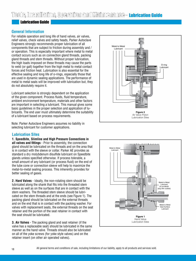
18 All general terms and conditions of sale, including limitations of our liability, apply to all products and services sold.
Tools, Installation, Operation and Maintenance - Lubrication GuideLubrication Guide
General InformationFor reliable operation and long life of hand valves, air valves, relief valves, check valves and safety heads, Parker Autoclave Engineers strongly recommends proper lubrication of all components that are subject to friction during assembly and /or operation. This is especially important where metal to metal contact occurs such as on connection gland threads, packing gland threads and stem threads. Without proper lubrication, the high loads imposed on these threads may cause the parts to weld (or gall) together from the high metal to metal contact forces and friction heat. Lubrication is also essential for the effective sealing and long life of o-rings, especially those that are used in dynamic sealing applications. The performance of metal to metal seals will be improved with lubrication but, they do not absolutely require it.
Lubricant selection is strongly dependent on the application of the given component. Process fluids, fluid temperature, ambient environment temperature, materials and other factors are important in selecting a lubricant. This manual gives some basic guidelines in the proper selection and application of lu-bricants. The end user must ultimately determine the suitability of a lubricant based on process requirements.
Note: Parker Autoclave Engineers assumes no liability in selecting lubricant for customer applications.
Lubrication Sites1. Speedbite, Slimline and High Pressure Connections in all valves and fittings - Prior to assembly, the connection gland should be lubricated on the threads and on the area that is in contact with the sleeve or collar. Parker AE provides as standard a dry molybdenum disulfide lubricant on Speedbite glands unless specified otherwise. If process tolerable, a small amount of any lubricant (or process fluid) on the end of the tube cone or connection sleeve will help to maximize the metal-to-metal sealing process. This inherently provides for better sealing of gases.
2. Hard Valves - Ideally, the non-rotating stem should be lubricated along the shank that fits into the threaded stem sleeve as well as on the surfaces that are in contact with the stem washers. The threaded stem sleeve should be lubri-cated on the stem threads and at the ends (see Figure 1). The packing gland should be lubricated on the external threads and on the end that is in contact with the packing washer. For valves with replacement seats, the external threads on the seat retainer and the portion of the seat retainer in contact with the seat should be lubricated.
3. Air Valves - The packing gland and seat retainer (if the valve has a replaceable seat) should be lubricated in the same manner as the hand valve. Threads should also be lubricated on all of the yoke screws (for yoke style valves) and on the retainer insert (on other air operated valves).
Figure 2Air Valve Piston
Lubrication Sites
Metal to MetalLubricant
O-ringLubricant
Metal to MetalLubricant
Metal to MetalLubricant
(If not MoS2{dry} film coated)
Metal to MetalSeal Surface
Lubricant
Figure 1Hand Valve
Lubrication Sites

19All general terms and conditions of sale, including limitations of our liability, apply to all products and services sold.
For piston type air operators, o-ring lubricant should be applied to the inside of the operator housing, on the center rod and on all the o-rings, on the pistons and divider plates. On air-to-open diaphragm operators, the o-ring on the stem should be lubricated. The threads and end of the spring adjust-ment screw should be lubricated on all air-to-open valves. Refer to Figure 2 and 3 for lubrication sites on piston and diaphragm style operators.
4. Check Valves - The gland nut should be lubricated on the external threads and at the end where it contacts the cover. The cover should be lubricated at the sealing surface where it contacts the body. For o-ring check valves, a small amount of o-ring lubricant on the o-ring will help swell the elastomer and aid sealing. Refer to Figure 4 for lubrication sites on check valves.
5. Relief Valves - Threads should be lubricated on the cap, spring cylinder, adjustment bolt and on the seat gland. Refer to Figure 5 for lubrication sites on the relief valve.
6. Safety Heads - The threads and end of the hold down nut should be lubricated. Refer to figure 6 for lubrication sites on the safety head.
For any part not covered in the above statements, the general rule is that parts that will move against each other during assembly or operation should be lubricated at the points/areas of contact.
Recommended LubricantsNote: This information is provided for reference only. The manufacture of the lubricant should be contacted for specific information based on your application. Refer to the material safety data sheets for information on safe usage and storage methods for these lubricants.
Figure 3Air Valve (Diaphragm)
Lubrication Sites
1. Jet Lube SS-301 - This lubricant consists of pure copper flakes that are homogenized into a non-melting, nonvolatile viscous carrier. It is fortified with anti-oxidants, rust and cor-rosion inhibitors. Jet Lube SS-30 is the standard lubricant for Parker Autoclave VFT components with sliding metal to metal contact surfaces. The surfaces are copper coated and prevents seizure, galling and heat freeze. SS-30 comes in the form of a thick oil that can be easily brushed on the surfaces to be lubricated. The absolute service temperature range is from 0 to 1800°F (-17.8 to 982°C). Jet Lube SS-30 is not recommended for extreme low temperature applications or processes that will not tolerate the presence of copper.
2. Jet Lube MP-50 Moly Paste1 - This is a thick paste that contains molybdenum disulfide (MoS). This lubricant is suitable for preventing seizure and galling of parts at absolute temperatures of -300 to 750°F (-184 to 399°C). It is recom-mended for metal to metal components that are exposed to temperatures of less than 0ºF. Other lubricants may solidify under these conditions and prevent the effective operation of dynamic components.
3. DuPont Krytox 240AC2 - Krytox is a non-flammable fluorinated grease used for metal to metal lubrication in valves that are cleaned and designated for oxygen service. It comes in the form of a white grease and has a recommended absolute service temperature range of -15 to 500°F (-26.1 to 260°C).
4. Molycoat 55M4 (Dow Corning) - This grease is used for static lubrication between rubber and metal parts in ball valves and o-ring check valves. It is a silicone based lubricant and meets Military Specifications MIL-G-4343. It is not recom-mended for use on silicone rubber o-rings and seals. It has a recommended absolute service temperature range of -85 to 350°F (-65 to 177°C).
5. Neolube DAG 1563 - This is a dry film lubricant for valves used in Navy Nuclear service. It consists of graphite particles in a thermoplastic resin and ispropanol and meets Military Specification MIL-L-24131B. The dry film form allows tight control of impurities that are required for these applications. It has an absolute service temperature of -100 to 400°F.
6. LubriPlate-NSF H-1 Registered, Extremely Tacky, Food Grade Greases - This grease is used for dynamic lubrication between rubber and metal parts in pneumatic systems such as piston style air operators. A tacky, adhesive, highly water resistant grease for medium to slow dynamic speeds. It has a recommended absolute service temperature range of -0 to 350°F (-17.8 tp 177°C).
Figure 4Check Valve
Lubrication Sites
Metal to MetalLubricant
O-ringLubricant

02-0140SE January2013© 2013 Parker Hannifin Corporation | Autoclave Engineers is a registered trademark of the Parker Hannifin Corporation
Parker Hannifin Manufacturing Ltd. Instrumentation Products Division, Europe Industrial Estate WhitemillWexford, Republic of IrelandPH: 353 53 914 1566FAX: 353 53 914 1582
Instrumentation Products DivisionAutoclave Engineers Operation8325 Hessinger DriveErie, Pennsylvania 16509-4679 USAPH: 814-860-5700 FAX: 814-860-5811www.autoclave.com
WARNING
FAILURE, IMPROPER SELECTION OR IMPROPER USE OF THE PRODUCTS AND/OR SYSTEMS DESCRIBED HEREIN OR RELATED ITEMS CAN CAUSE DEATH, PERSONAL INJURY AND PROPERTY DAMAGE.This document and other information from Parker Hannifin Corporation, its subsidiaries and authorized distributors provide product and/or system options for further investigation by users having technical expertise. It is important that you analyze all aspects of your application and review the information concerning the product or system in the current product catalog. Due to the variety of operating conditions and applications for these products or systems, the user, through its own analysis and testing, is solely responsible for making the final selection of the products and systems and assuring that all performance, safety and warning requirements of the application are met. The products described herein, including without limitation, product features, specifications, designs, availability and pricing, are subject to change by Parker Hannifin Corporation and its subsidiaries at any time without notice.
Offer of Sale
The items described in this document are available for sale by Parker Hannifin Corporation, its subsidiaries or its authorized distributors. Any sale contract entered by Parker will be governed by the provisions stated in Parker's standard terms and conditions of sale (copy available upon request).
ISO-9001 Certified
Caution! Do not mix or interchange parts or tubing with those of other manufacturers. Doing so is unsafe and will void warranty.
Caution! Parker Autoclave Engineers Valves, Fittings and Tools are not designed to work with common commercial instrument tubing and will only work with tubing built to Parker Autoclave Engineers AES Specifications. Failure to do so will void warranty.
For service, contact the Parker Autoclave Engineers’ Representative in your area, or FAX Parker Autoclave Engineers’ Customer Support Services at 1-814-860-5703.
Figure 5Relief Valve
Lubrication Sites
Figure 6Safety Head
Lubrication Sites
Metal to Metal Lubricant
Metal to MetalSeal Surface Lubricant
Metal to MetalLubricant
Tools, Installation, Operation and Maintenance - Lubrication GuideServices
Lubrication Selection Chart
Notes: Specific applications may require other service temperature ranges. 1SS-30 and MP-50 Moly Paste are registered trademarks of Jet Lube Inc. 2Krytox is a registered trademark of E.I.duPont de Nemours & Co., Inc. 3DAG is a registered trademark of Acheson Industries, Inc. 4Molycoat and Dow Corning are registered trademarks of Dow Corning Corp
Lubrication Part No. Application Absolute Service Temperature Range
Jet-Lube SS-30 P-3580 Metal to Metal, Standard Application 0°F to 1800°F (-18°C to 982°C)
Jet-Lube Moly Paste MP-50 P-9766 Metal to Metal, Low Temperature Application -300°F to 750°F (-185°C to 398°C)
Krytox 240 AC 53893 Metal to Metal, Oxygen Clean Components -15°F to 500°F (-26°C to 260°C)
MolyKote 55 Dow Corning 90085 Check Valve Ball and Poppet Lubricant -85°F to 350°F (-65°C to 177°C)
Neolube DAG 156 90406 Metal to Metal, Nuclear Service -100°F to 400°F (-73°C to 204°C)
LubriPlate Pure Tac P-9981 Dynamic O-ring Seals-Air Operator Housing 0°F to 350°F (-18°C to 177°C)

1All general terms and conditions of sale, including limitations of our liability, apply to all products and services sold.
The information presented in this section is intended to assist designers in the proper selection of Parker Autoclave Engi-neers’ valves, fittings and tubing for fluid handling systems. This technical data does not represent product specifications but rather guidelines for direction in the proper application of the referenced equipment. These guidelines are general in nature because of the many process variables.
For severe service applications, selection of the appropriate valves, fittings and tubing is essential in order to optimize the service life of these products. Parker Autoclave Engineers’ technical staff is available to assist in the interpretation of this information.
Technical InformationTechnical Inform
ation
www.autoclave.comwww.autoclave.com

2 All general terms and conditions of sale, including limitations of our liability, apply to all products and services sold.
Technical Information - General InformationTechnical and Application Information
Materials:
Widely varying conditions frequently require that valves, fittings and tubing be constructed of materials other than con-ventional stainless steel. Since many variables affect the corro-sion resistance of metallic materials, it is Parker Autoclave Engineers’ policy not to recommend materials based on corrosion resistance for specific fluid applications. We can, however, suggest materials based on mechanical strength and also indicate materials generally used in a specific application. Other materials not listed in this section are also available.
Pressure:
Included in this section are the standard pressure ratings for several common materials for valves and fittings as well as tubing. Parker Autoclave Engineers stocks a select quantity of special material tubing for immediate delivery.
Temperature:
Also contained in this section are pressure reduction factors at various temperatures for several materials. To obtain the maximum pressure rating at an elevated temperature, multiply the maximum pressure rating of the item at room temperature by the elevated temperature factor (% of RT).
High and low temperatures or high heat up and/or cool down rates can affect the capability of a metal-to-metal seal. When selecting a valve series, consideration should not only be given to static pressure rating, but also static and dynamic temperature conditions. Generally, the smaller the seal diam-eter of a metal-to-metal seal, the more reliable the seal will be.
Gas or Liquid Service:
Light gases such as hydrogen and helium are more difficult to seal than liquids. When selecting a valve series, consideration should be given to the fluid application and not just pressure and temperature requirements. The higher the rating of the valve or fitting, the less the likelihood of weepage problems with light gases. Tubing selections should also consider the service requirements, since thicker wall, smaller outside diameter tube sizes will produce a more reliable connection seal. Handling of fittings and tubing during installation will make a difference in sealability of light gases as well as liquids. Do not handle the tube or fitting in such a way as to damage the sealing surfaces. If it is process tolerable, a small amount of lubrication (or even process fluid) on the seal area during installation will help the sealing process. Refer to the Tools, Installation, Operation and Maintenance section for further information.
Valve Stem Packing Materials:
The considerations listed thus far should be applied when selecting a suitable valve stem packing material (PTFE, PTFE glass or Graphite yarn). Where possible, PTFE packing is the most reliable, low maintenance, packing choice; PTFE/glass is the second. While graphite yarn packing is a reliable pack-
ing material for the majority of extremely high temperature applications, some gases may permeate more readily through graphite yarn packing than through the PTFE packing in a valve with an extended stuffing box. The packing material must be kept below the maximum permitted temperature listed on page 5.
Valve Stem Seating:
Abrasive flow or high cycle service will require more frequent maintenance. Special materials and the proper valve series selection may extend service life. For example, if flow is not critical, a 30VM valve with an N-Dura stem will require less maintenance than an SW series valve used in a low pressure, high cycle, abrasive flow application. Although all application parameters cannot be considered in this section, the user can generally expect several thousand cycles in a liquid application and several hundred cycles for gas service. The packing gland may require adjustment, however, to achieve these results.
Pressure Cycling:
In medium and high pressure applications, static as well as dynamic (cyclic) pressure must be considered when selecting an appropriate valve series. If fatigue life is a concern, Parker Autoclave Engineers can supply tubing which has been auto-frettaged for improved fatigue resistance. For internally pres-surized tubing, autofrettaging is a method by which the inner wall of the tube is precompressed to reduce the tube operating bore stresses. By applying sufficient internal pressure, greater than the maximum working pressure of the tube, the inner wall is plastically deformed by a controlled amount. The remain-ing outer portion of the wall acts elastically, and when the pressure is released, a positive compressive load at the bore will exist. As mentioned previously, the result is reduced bore stress and increased fatigue life. In addition to the autofrettag-ing method to increase cycle life, Parker Autoclave Engineers offers HP-HC (high-pressure — high cycle) tubing, rated to 100,000 psi (6895 bar). This tubing can be substituted for our standard 60,000 psi (4137 bar) tubing providing longer life at 60,000 psi (4137 bar) operation.
Vacuum Service:
The high, medium and low pressure series of Parker Autoclave Engineers’ standard valves, fittings and tubing can be used in light vacuum services to 10-2 torr. For high vacuums to 10-5 or
10-6 torr, Parker Autoclave Engineers’ high pressure series is recommended. Extreme care and proper seal lubrication is re-quired (as mentioned in the Gas or Liquid Service paragraph) to achieve these degrees of vacuum. The pump type and size will determine the final vacuum pressure.
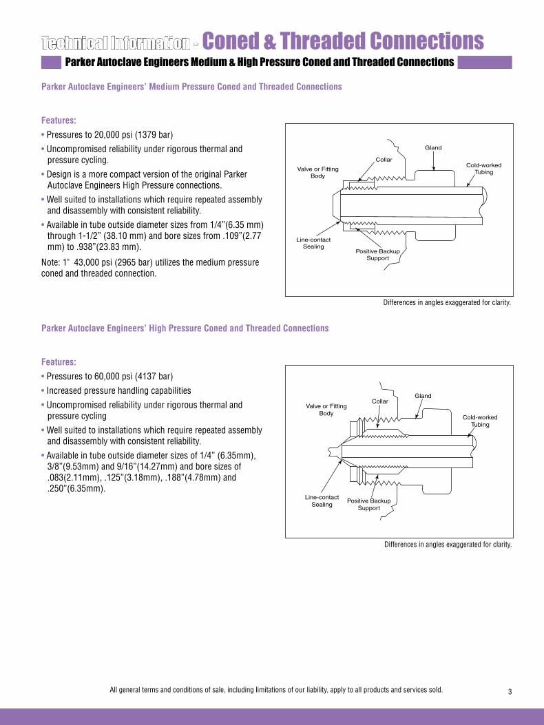
3All general terms and conditions of sale, including limitations of our liability, apply to all products and services sold.
Technical Information - Coned & Threaded ConnectionsParker Autoclave Engineers Medium & High Pressure Coned and Threaded Connections
Parker Autoclave Engineers’ Medium Pressure Coned and Threaded Connections
Features:
• Pressures to 20,000 psi (1379 bar)
• Uncompromised reliability under rigorous thermal and pressure cycling.
• Design is a more compact version of the original Parker Autoclave Engineers High Pressure connections.
• Well suited to installations which require repeated assembly and disassembly with consistent reliability.
• Available in tube outside diameter sizes from 1/4”(6.35 mm) through 1-1/2” (38.10 mm) and bore sizes from .109”(2.77 mm) to .938”(23.83 mm).
Note: 1" 43,000 psi (2965 bar) utilizes the medium pressure coned and threaded connection.
Parker Autoclave Engineers’ High Pressure Coned and Threaded Connections
Features:
• Pressures to 60,000 psi (4137 bar)
• Increased pressure handling capabilities
• Uncompromised reliability under rigorous thermal and pressure cycling
• Well suited to installations which require repeated assembly and disassembly with consistent reliability.
• Available in tube outside diameter sizes of 1/4” (6.35mm), 3/8”(9.53mm) and 9/16”(14.27mm) and bore sizes of .083(2.11mm), .125”(3.18mm), .188”(4.78mm) and .250”(6.35mm).
Valve or FittingBody
Collar
Gland
Cold-workedTubing
Positive Backup Support
Line-contactSealing
Valve or FittingBody
CollarGland
Cold-workedTubing
Positive Backup Support
Line-contactSealing
Differences in angles exaggerated for clarity.
Differences in angles exaggerated for clarity.
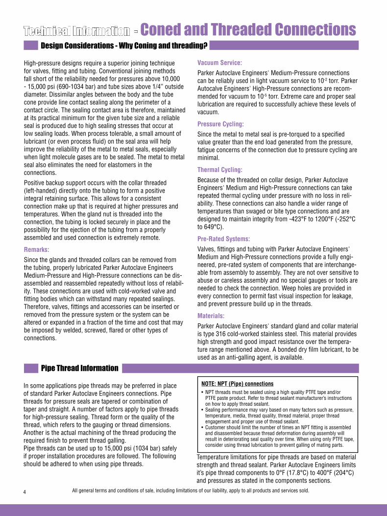
4 All general terms and conditions of sale, including limitations of our liability, apply to all products and services sold.
Technical Information - Coned and Threaded ConnectionsDesign Considerations - Why Coning and threading?
High-pressure designs require a superior joining technique for valves, fitting and tubing. Conventional joining methods fall short of the reliability needed for pressures above 10,000 - 15,000 psi (690-1034 bar) and tube sizes above 1/4” outside diameter. Dissimilar angles between the body and the tube cone provide line contact sealing along the perimeter of a contact circle. The sealing contact area is therefore, maintained at its practical minimum for the given tube size and a reliable seal is produced due to high sealing stresses that occur at low sealing loads. When process tolerable, a small amount of lubricant (or even process fluid) on the seal area will help improve the reliability of the metal to metal seals, especially when light molecule gases are to be sealed. The metal to metal seal also eliminates the need for elastomers in the connections.
Positive backup support occurs with the collar threaded (left-handed) directly onto the tubing to form a positive integral retaining surface. This allows for a consistent connection make up that is required at higher pressures and temperatures. When the gland nut is threaded into the connection, the tubing is locked securely in place and the possibility for the ejection of the tubing from a properly assembled and used connection is extremely remote.
Remarks:
Since the glands and threaded collars can be removed from the tubing, properly lubricated Parker Autoclave Engineers Medium-Pressure and High-Pressure connections can be dis-assembled and reassembled repeatedly without loss of relabil-ity. These connections are used with cold-worked valve and fitting bodies which can withstand many repeated sealings. Therefore, valves, fittings and accessories can be inserted or removed from the pressure system or the system can be altered or expanded in a fraction of the time and cost that may be imposed by welded, screwed, flared or other types of connections.
Vacuum Service:
Parker Autoclave Engineers' Medium-Pressure connections can be reliably used in light vacuum service to 10-2 torr. Parker Autocalve Engineers' High-Pressure connections are recom-mended for vacuum to 10-5 torr. Extreme care and proper seal lubrication are required to successfully achieve these levels of vacuum.
Pressure Cycling:
Since the metal to metal seal is pre-torqued to a specified value greater than the end load generated from the pressure, fatigue concerns of the connection due to pressure cycling are minimal.
Thermal Cycling:
Because of the threaded on collar design, Parker Autoclave Engineers' Medium and High-Pressure connections can take repeated thermal cycling under pressure with no loss in reli-ability. These connections can also handle a wider range of temperatures than swaged or bite type connections and are designed to maintain integrity from -423°F to 1200°F (-252°C to 649°C).
Pre-Rated Systems:
Valves, fittings and tubing with Parker Autoclave Engineers' Medium and High-Pressure connections provide a fully engi-neered, pre-rated system of components that are interchange-able from assembly to assembly. They are not over sensitive to abuse or careless assembly and no special gauges or tools are needed to check the connection. Weep holes are provided in every connection to permit fast visual inspection for leakage, and prevent pressure build up in the threads.
Materials:
Parker Autoclave Engineers' standard gland and collar material is type 316 cold-worked stainless steel. This material provides high strength and good impact resistance over the tempera-ture range mentioned above. A bonded dry film lubricant, to be used as an anti-galling agent, is available.
In some applications pipe threads may be preferred in place of standard Parker Autoclave Engineers connections. Pipe threads for pressure seals are tapered or combination of taper and straight. A number of factors apply to pipe threads for high-pressure sealing. Thread form or the quality of the thread, which refers to the gauging or thread dimensions. Another is the actual machining of the thread producing the required finish to prevent thread galling. Pipe threads can be used up to 15,000 psi (1034 bar) safely if proper installation procedures are followed. The following should be adhered to when using pipe threads.
NOTE: NPT (Pipe) connections• NPT threads must be sealed using a high quality PTFE tape and/or PTFE paste product. Refer to thread sealant manufacturer’s instructions on how to apply thread sealant.• Sealing performance may vary based on many factors such as pressure, temperature, media, thread quality, thread material, proper thread engagement and proper use of thread sealant.• Customer should limit the number of times an NPT fitting is assembled and disassembled because thread deformation during assembly will result in deteriorating seal quality over time. When using only PTFE tape, consider using thread lubrication to prevent galling of mating parts.
Temperature limitations for pipe threads are based on material strength and thread sealant. Parker Autoclave Engineers limits it’s pipe thread components to 0°F (17.8°C) to 400°F (204°C) and pressures as stated in the components sections.
Pipe Thread Information

5All general terms and conditions of sale, including limitations of our liability, apply to all products and services sold.
Technical Information - Pressure/Temperature Rating GuidePressure/temperature Rating Guide
Information in this rating guide is furnished to approximate the pressure/temperature capabilities of Parker Autoclave Engineers valves and fittings with various options.
To determine approximate ratings, the following factors should be considered:
• Refer to valve or fitting ordering pages for the base pressure rating of component at room temperature (R.T.).
• Refer to Technical Information section for pressure ratings of materials at elevated temperatures.
• Refer to appropriate tubing section for pressure ratings of standard Parker Autoclave Engineers' tubing at various tem-peratures to 800°F (427°C).
• Note maximum temperature ratings for Parker Autoclave Engineers' valves with various packing and stem options in table below.
• Note pressure/temperature curve on page 6 for type 316 stainless steel bodies and tubing.
• Note temperature information checklist on page 6.
10V Vee or Reg., Metal-to-Metal -100 (-73) 450 (232) NA NA -100 (-73) 600 (316) 0 (-17.8) 8002 (427)
SW Vee or Reg., Metal-to-Metal -100 (-73) 450 (232) NA NA -100 (-73) 600 (316) 0 (-17.8) 8002 (427)
10SM/20SM Vee or Reg., Metal-to-Metal -100 (-73) 450 (232) NA NA -100 (-73) 600 (316) 0 (-17.8) 800 (427)
30SC Vee or Reg., Metal-to-Metal -100 (-73) 450 (232) NA NA -100 (-73) 600 (316) NA NA
30VM Vee or Reg., Metal-to-Metal -100 (-73) 450 (232) NA NA -100 (-73) 600 (316) 0 (-17.8) 800 (427)
40VM Vee or Reg., Metal-to-Metal NA NA 40 (4.4) 230 (110) -100 (-73) 600 (316) 0 (-17.8) 800 (427)
60VM Vee or Reg., Metal-to-Metal NA NA 40 (4.4) 230 (110) -100 (-73) 600 (316) 0 (-17.8) 800 (427)
100VM Vee Stem, Metal-to-Metal NA NA 40 (4.4) 230 (110) NA NA NA NA
15Y Vee or Reg., Metal-to-Metal -100 (-73) 450 (232) NA NA -100 (-73) 600 (316) 0 (-17.8) 800 (427)
50Y Vee or Reg., Metal-to-Metal -100 (-73) 450 (232) NA NA NA NA 0 (-17.8) 800 (427)
10VRMM Micrometering -100 (-73) 450 (232) NA NA -100 (-73) 600 (316) 0 (-17.8) 8002 (427)
30VRMM Micrometering -100 (-73) 450 (232) NA NA -100 (-73) 600 (316) 0 (-17.8) 800 (427)
60VRMM Micrometering NA NA 40 (4.4) 230 (110) -100 (-73) 600 (316) 0 (-17.8) 800 (427)
(No Suffix Required) (Add “TG” toOrder Number)
(Add “GY” toOrder Number)
Min Max Min Max Min Max Min Max
StandardPTFE
Packing
StandardNylon-Leather
OptionalPTFEGlass2
OptionalGraphite
Yarn1
OptionalExtended
Stuffing Box
See page 2of Extreme Tem-perature Series Needle Valve
Section for information
on extended stuffing box.
Caution: While testing has shown O-rings to provide satisfactory service life, both cyclic and shelf life may vary widely with differing service conditions, properties of reactants, pressure and temperature cycling and age of the O-ring. FREQUENT INSPECTION SHOULD BE MADE to detect any deterioration, and O-rings replaced as required.
Note:1. Optional graphite-yarn packing not recommended for hydrogen or helium service.2. 40VM, 60VM and 60VRMM valves use Peak/PTFE/Peak for the PTFE glass option.
3. Compression sleeve-type connections such as Parker Autoclave Engineers’ UniVersaLok, Parker Autoclave Engineers’ SpeedBite or other swaged or bite-type connections are not recommended for ser-vice above 650°F (343°C) or below 0°F (-17.8°C). For such applica-tions, Parker Autoclave Engineers recommends its medium pressure components with Parker Autoclave Engineers Medium Pressure coned-and -threaded connections, offering excellent thermal cycling capability.
4. Pressure Limitations: Consult factory on 3/4 and 1 inch sizes.
Stem TypeValve Stem
Packing Temperature: °F (°C)
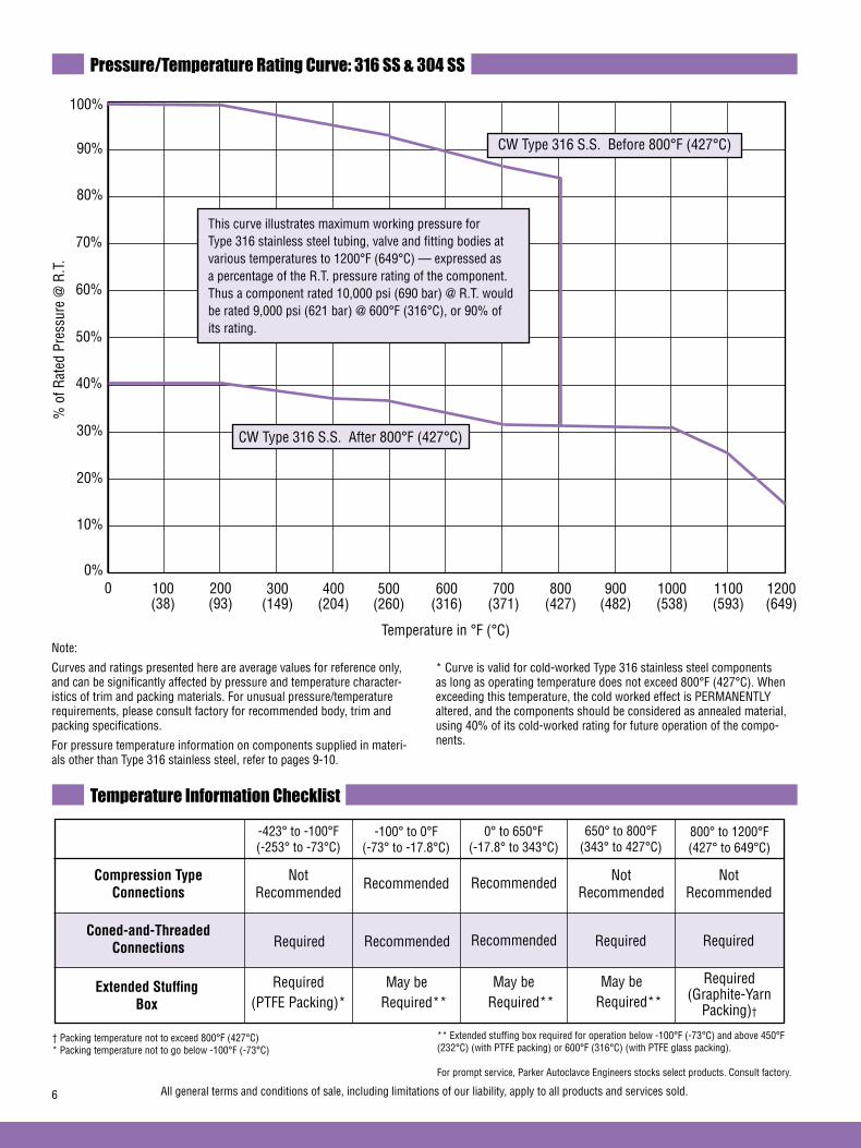
6 All general terms and conditions of sale, including limitations of our liability, apply to all products and services sold.
Pressure/Temperature Rating Curve: 316 SS & 304 SS
100%
0%
90%
80%
70%
60%
50%
40%
30%
20%
10%
% o
f Rat
ed P
ress
ure
@ R
.T.
0 100(38)
200(93)
300(149)
400(204)
500(260)
600(316)
700(371)
800(427)
900(482)
1000(538)
1100(593)
1200(649)
This curve illustrates maximum working pressure for Type 316 stainless steel tubing, valve and fitting bodies at various temperatures to 1200°F (649°C) — expressed as a percentage of the R.T. pressure rating of the component. Thus a component rated 10,000 psi (690 bar) @ R.T. would be rated 9,000 psi (621 bar) @ 600°F (316°C), or 90% of its rating.
Temperature in °F (°C)
CW Type 316 S.S. After 800°F (427°C)
CW Type 316 S.S. Before 800°F (427°C)
Note:
Curves and ratings presented here are average values for reference only, and can be significantly affected by pressure and temperature character-istics of trim and packing materials. For unusual pressure/temperature requirements, please consult factory for recommended body, trim and packing specifications.
For pressure temperature information on components supplied in materi-als other than Type 316 stainless steel, refer to pages 9-10.
* Curve is valid for cold-worked Type 316 stainless steel components as long as operating temperature does not exceed 800°F (427°C). When exceeding this temperature, the cold worked effect is PERMANENTLY altered, and the components should be considered as annealed material, using 40% of its cold-worked rating for future operation of the compo-nents.
Temperature Information Checklist
Compression Type Not Not Not Connections Recommended Recommended Recommended
Recommended
Coned-and-Threaded Connections Recommended
Extended Stuffing Box
-423° to -100°F (-253° to -73°C)
-100° to 0°F (-73° to -17.8°C)
0° to 650°F (-17.8° to 343°C)
650° to 800°F (343° to 427°C)
800° to 1200°F (427° to 649°C)
† Packing temperature not to exceed 800°F (427°C)* Packing temperature not to go below -100°F (-73°C)
** Extended stuffing box required for operation below -100°F (-73°C) and above 450°F (232°C) (with PTFE packing) or 600°F (316°C) (with PTFE glass packing).
For prompt service, Parker Autoclavce Engineers stocks select products. Consult factory.
Required Recommended Required Required
Required (PTFE Packing)*
May be Required**
May be Required**
May be Required**
Required (Graphite-Yarn
Packing)†
Recommended

7All general terms and conditions of sale, including limitations of our liability, apply to all products and services sold.
Technical Information - Material vs. Pressure RatingParker Autocalve Engineers Valves, Fittings and Tubing
ValveSeries
ConnectionType
TubeSize(in.) 316CW (Std.) Hastelloy C276 Inconel 600 Monel 400 Nickel 200 Titanium Gr2 Titanium 6AL4V
10V
SW
20SM
30VM
60VM
W125 1/8 15,000 (1034) 11,000 (758) 11,000 (758) 11,000 (758) 9,900 (683) 6,000 (414) 7,500 (531) 11,000 (758)
W250 1/4 15,000 (1034) 11,500 (793) 11,500 (793) 11,500 (793) 9,900 (683) 6,000 (414) 7,500 (531)) 11,500 (793)
W375 3/8 15,000 (1034) 7,500 (517) 7,500 (517) 7,500 (517) 6,300 (434) 3,800 (262) 4,800 (331) 7,500 (517)
W500 1/2 10,000 (690) 5,500 (379) 5,500 (379) 5,500 (379) 4,600 (317) 2,700 (186) 3,400 (234) 5,500 (379)
SW250 1/4 15,000 (1034) 9,600 (662) 7,700 (531) 12,500 (862) 6,300 (434) 3,800 (262) 4,800 (331) 11,500 (793)
SW375 3/8 15,000 (1034) 7,500 (517) 7,500 (517) 7,500 (517) 6,300 (434) 3,800 (262) 4,800 (331) 7,500 (517)
SW500 1/2 10,000 (690) 5,500 (379) 5,500 (379) 5,500 (379) 4,600 (317) 2,700 (186) 3,400 (234) 5,500 (379)
SF562CX10 9/16 10,000 (690) 10,000 (690) 9,300 (641) 10,000 (690) 6,600 (455) 4,000 (276) 6,600 (455) 10,000 (690)
SF70CX10 3/4 10,000 (690) 10,000 (690) 9,300 (641) 10,000 (690) 6,600 (455) 4,000 (276) 6,600 (455) 10,000 (690)
SF1000CX10 1 10,000 (690) 10,000 (690) 9,300 (641) 10,000 (690) 6,600 (455) 4,000 (276) 6,600 (455) 10,000 (690)
SF250CX 1/4 20,000 (1379) 12,200 (841) 9,300 (641) 15,000 (1034) 6,600 (455) 4,000 (276) 6,600 (455) 20,000 (1379)
SF375CX 3/8 20,000 (1379) 12,200 (841) 9,300 (641) 15,000 (1034) 6,600 (455) 4,000 (276) 6,600 (455) 20,000 (1379)
SF562CX20 9/16 20,000 (1379) 12,200 (841) 15,000 (1034) 20,000 (1379)
SF750CX20 3/4 20,000 (1379) 12,200 (841) 15,000 (1034) 20,000 (1379)
SF1000CX20 1 20,000 (1379) 12,200 (841) 15,000 (1034) 20,000 (1379)
F250C 1/4 30,000 (2068) 22,400 (1544) 17,300 (1193) 22,500 (1551) 13,000 (896) 8,200 (565) 15,200 (1048) 30,000 (2068)
F375C 3/8 30,000 (2068) 22,400 (1544) 17,300 (1193) 22,500 (1551) 13,000 (896) 8,200 (565) 15,200 (1048) 30,000 (2068)
F562C 9/16 30,000 (2068) 22,400 (1544) 17,300 (1193) 22,500 (1551) 13,000 (896) 8,200 (565) 15,200 (1048) 30,000 (2068)
F562C40 9/16 40,000 (2758) 23,500 (1620) 18,400 (1269) 27,000 (1862) 13,800 (951) 8,700 (600) 16,200 (1117) 40,000 (2758)
F250C 1/4 60,000 (4137) 35,900 (2475) 27,700 (1910) 35,900 (2475) 20,800 (1434) 13,100 (903) 24,300 (1675) 60,000 (4137)
F375C 3/8 60,000 (4137) 35,900 (2475) 27,700 (1910) 35,900 (2475) 20,800 (1434) 13,100 (903) 24,300 (1675) 60,000 (4137)
F562C 9/16 60,000 (4137) 35,900 (2475) 27,700 (1910) 35,900 (2475) 20,800 (1434) 13,100 (903) 24,300 (1675) 60,000 (4137)
Material vs. Pressure Rating psi (bar) @ Room Temperature *
Valves & Fittings
* For ratings at elevated temperatures see P/T Rating Curves on pages 9 and 10. Tubing, connection type and/or packing material may limit maximum temperature rating. See pages 5 and 6 for further temperature limitations.
ValveSeries
Tubing Size Outside x Inside
Diameter Inches (mm)
Low
Pre
ssur
e
Material vs. Pressure Rating psi (bar) @ Room Temperature ††*
Tubing (Seamless) - Low Pressure**
1/16 x 0.026 15,000 15,000 15,000 15,000 11,500 7,100 11,500 (1.59 x 0.66) (1034.20) (1034.20) (1034.20) (1034.20) (792.88) (489.52 (792.88
1/8 x 0.052 15,000 15,000 15,000 15,000 12,000 7,200 12,000 (3.19 x 1.32) (1034.20) (1034.20) (1034.20) (1034.20) (827.36) (496.41) (827.36)
1/8 x 0.062 11,650 14,000 11,000 11,650 9,900 6,000 7,500 (3.19 x 1.57) (803.23) (965) (758.41) (803.23) (682.57) (413.68) (517.10)
1/8 x 0.069 9,950 11,000 10,600 11,500 9,300 5,300 6,650 (3.19 x 1.75) (686.02) (758.41) (730.83) (792.88) (641.26) (365.42) (458.49)
1/8 x 0.085 6,850 7,750 7,300 10,000 6,400 3,650 4,450 (3.19 x 2.16) (472.28) (534.34) (503.31) (689.46) (441.26) (251.65) (306.81)
1/4 x 0.125 11,650 11,500 11,500 12,500 9,900 6,000 7,500 (6.35 x 3.18) (803.23) (792.88) (792.88) (861.83) (682.57) (413.68) (517.10)
1/4 x 0.180 5,450 6,650 6,300 9,000 5,500 3,150 3,900 (6.35 x 4.57) (375.76) (458.49) (434.36) (620.52) (379.21) (217.18) (268.89)
1/4 x 0.194 4,600 5,200 4,900 7,200 4,300 2,450 3,050 (6.35 x 4.93) (317.15) (358.52) (337.84) (496.41) (296.47) (168.92) (210.29)
316CW† Hastelloy C276 Inconel 600 Monel 400 Nickel 200 Titanium Gr2
10SM
†† The tubing pressure rating in some instances is lower than the rating of the valve and fitting. Tubing connection type and/or packing material may limit maximum temperature rating. See pages 5 & 6 for further temperature limitations.
† Except low pressure series which is 316 annealed.* For ratings at elevated temperatures see P/T Rating Curves on pages 9 & 10.** Except Hastelloy C276 which is welded and drawn or seamless.
Tubing (Seamless) - Low Pressure, continued on page 8
Inconel 625
Inconel 625
40VM
uUse 10SM SeriesNote: Hastelloy C276 values for SW are based on the valve ratings.
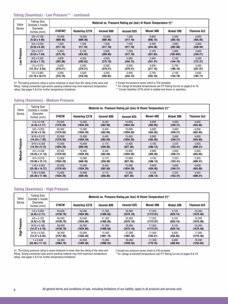
8 All general terms and conditions of sale, including limitations of our liability, apply to all products and services sold.
ValveSeries
316CW Hastelloy C276 Monel 400 Nickel 200 Titanium Gr2
Med
ium
Pre
ssur
e
1/4 x 0.109 20,000 15,000 8,450 15,000 6,600 3,600 6,600 (6.35 x 2.77) (1378.93) (1034.20) (582.60) (1034.20) (455.05) (248.21) (455.05)
3/8 x 0.203 20,000 15,000 8,450 15,000 6,600 3,600 6,600 (9.53 x 5.16) (1378.93) (1034.20) (582.60) (1034.20) (455.05) (248.21) (455.05)
9/16 x 0.312 20,000 15,000 8,450 15,000 6,600 3,600 6,600 (14.29 x 7.92) (1378.93) (1034.20) (582.60) (1034.20) (455.05) (248.21) (455.05)
9/16 x 0.359 15,000 10,000 5,175 12,000 4,150 2,225 5,925 (14.29 x 9.12) (1034.20) (689.46) (356.80) (827.36) (286.13) (153.41) (408.51)
3/4 x 0.438 20,000 15,000 8,450 15,000 6,600 3,600 6,600 (19.05 x 11.13) (1378.93) (1034.20) (582.60) (1034.20) (455.05) (248.21) (455.05)
3/4 x 0.516 15,000 10,000 5,175 12,000 4,150 2,225 5,925 (19.05 x 13.11) (1034.20) (689.46) (356.80) (827.36) (286.13) (153.41) (408.51)
1.00 x 0.562 20,000 15,000 8,450 15,000 6,600 3,600 6,600 (25.40 x 14.27) (1378.93) (1034.20) (582.60) (1034.20) (455.05) (248.21) (455.05)
1.00 x 0.688 15,000 10,000 5,175 12,000 4,150 2,225 5,925 (25.40 x 17.48) (1034.20) (689.46) (356.80) (827.36) (286.13) (153.41) (408.51)
Material vs. Pressure Rating psi (bar) @ Room Temperature ††*
Tubing (Seamless) - Medium Pressure
†† The tubing pressure rating in some instances is lower than the rating of the valve and fitting. Tubing connection type and/or packing material may limit maximum temperature rating. See pages 5 & 6 for further temperature limitations.
† Except low pressure series which is 316 annealed.* For ratings at elevated temperatures see P/T Rating Curves on pages 9 & 10.
ValveSeries
316CW Hastelloy C276 Monel 400 Nickel 200 Titanium Gr2
High
Pre
ssur
e
1/4 x 0.083 60,000 30,000 21,300 35,900 17,025 9,125 24,300 (6.35 x 2.11) (4136.79) (1934.98) (1468.56) (2475.18) (1173.81) (629.14) (1675.40)
3/8 x 0.125 60,000 30,000 21,300 35,900 17,025 9,125 24,300 (9.53 x 3.18) (4136.79) (1934.98) (1468.56) (2475.18) (1173.81) (629.14) (1675.40)
9/16 x 0.188 60,000 30,000 21,300 35,900 17,025 9,125 24,300 (14.27 x 4.78) (4136.79) (1934.98) (1468.56) (2475.18) (1173.81) (629.14) (1675.40)
9/16 x 0.250 40,000 23,000 15,400 27,000 11,000 6,600 17,600 (14.27 x 6.35) (2757.86) (1483.48) (1061.78) (1861.56) (758.41) (455.05) (1213.46)
1 x 0.438 43,000 23,000 15,900 28,000 11,300 6,800 18,200 (25.40 x 11.13) (2964.70) (1483.48) (1096.25) (1930.50) (779.10) (468.84) (1254.83)
Material vs. Pressure Rating psi (bar) @ Room Temperature ††*
Tubing (Seamless) - High Pressure
Tubing Size Outside x Inside
Diameter Inches (mm)
Tubing Size Outside x Inside
Diameter Inches (mm)
ValveSeries
Tubing Size Outside x Inside
Diameter Inches (mm)
Low
Pre
ssur
eMaterial vs. Pressure Rating psi (bar) @ Room Temperature ††*
Tubing (Seamless) - Low Pressure** - continued
3/8 x 0.195 10,000 10,000 10,000 7,500 8,800 5,300 6,600 (9.53 x 4.95) (689.46) (689.46) (689.46) (517.10) (606.73) (365.42) (455.05)
3/8 x 0.250 7,500 7,500 7,500 7,500 6,300 3,800 4,800 (9.53 x 6.35) (517.10) 517.10) (517.10) (517.10) (434.36) (262.00) (330.94)
3/8 x 0.277 5,450 6,150 5,800 7,500 5,100 2,900 3,600 (9.53 x 7.04) (375.76) (424.02) (399.89) (517.10) (351.63) (199.942) (248.21)
3/8 x 0.305 3,800 4,250 4,000 5,000 3,500 2,100 2,500 (9.53 x 7.75) (262.00) (293.02) (275.79) (344.73) (241.31) (144.79) (172.37)
1/2 x 0.375 5,500 5,500 5,500 5,500 4,600 2,700 3,450 (12.70 x 9.53) (379.21) (379.21) (379.21) (379.21) (317.15) (186.16) (237.87)
1/2 x 0.402 4,000 4,500 4,250 5,000 3,700 2,100 2,650 (12.70 x 10.21) (275.79) (310.26) (293.02) (344.73) (255.10) (144.79) (182.71)
316CW† Hastelloy C276 Inconel 600 Monel 400 Nickel 200 Titanium Gr2
†† The tubing pressure rating in some instances is lower than the rating of the valve and fitting. Tubing connection type and/or packing material may limit maximum temperature rating. See pages 5 & 6 for further temperature limitations.
† Except low pressure sereis which is 316 annealed.* For ratings at elevated temperatures see P/T Rating Curves on pages 9 & 10.** Except Hastelloy C276 which is welded and drawn or seamless.
Inconel 600
Inconel 600 Inconel 625
Inconel 625
Inconel 625

9All general terms and conditions of sale, including limitations of our liability, apply to all products and services sold.
Technical Information - Pressure vs. Temperature Rating Curves
s Maximum Coincident Metal Temperature s Maximum Coincident Metal Temperature
s Maximum Coincident Metal Temperature
Example: What would be the pressure rating of a 30VM 1/4 inch valve constructed of Hastelloy C276 at 600°F (316°C)?From the Material vs. Pressure rating chart on pages 7 & 8 for valves and fittings, the maximum pressure rating for a 30VM 1/4 inch valve constructed of Hastelloy C276 would be 22,400 psi (1544 bar).To determine the approximate pressure rating at 600°F (316°C), the Pressure vs. Temperature Rating Curves will be used. A vertical line on the x-axis (Temperature) is traced at 600°F (316°C) [on the Hastelloy C276 graph], until it intersects the curve. A horizontal line is then drawn to the y-axis (% of rated pressure @ RT) and read as 93%. The room temperature rating of the Hastelloy C276 valve is multiplied by the temperature reduction factor (.93) 22,400 psi (1544 bar) to approximate the temperature corrected pressure of 20,800 psi (1434 bar).See page 5 for further packing temperature limitations.
Curves and ratings presented here are average values for reference only and can be significantly affected by pressure and temperature characteristics of trim materials, stem packing materials (or o-rings), and connection type. Other options such as an extended stuffing box will be required to achieve the maximum temperature rating. See pages 5 and 6 for further temperature limitations. For unusual pressure/temperature requirements, please consult factory for recommended body, trim and packing specifications.To obtain the maximum pressure rating at an elevated temperature, multiply the maximum pressure rating of the item (in special material) at room temperature, by the elevated temperature factor (% of RT).
Inconel 600100
100(38)
90
80
70
60
50
40
30
20
10
0200(93)
300(149)
400(204)
500(260)
600(316)
700(371)
800(427)
900(482)
1000(538)
1100(593)
1200(649)
Temperature in °F (°C)
% o
f Roo
m T
empe
ratu
re R
atin
g

10 All general terms and conditions of sale, including limitations of our liability, apply to all products and services sold.
Technical Information - Pressure vs. Temperature Rating Curves
s Maximum Coincident Metal Temperature s Maximum Coincident Metal Temperature
s Maximum Coincident Metal Temperature
Curves and ratings presented here are average values for reference only and can be significantly affected by pressure and temperature characteristics of trim materials, stem packing materials (or o-rings), and connection type. Other options such as an extended stuffing box will be required to achieve the maximum temperature rating. See pages 5 and 6 for further temperature limitations. For unusual pressure/temperature requirements, please consult factory for recommended body, trim and packing specifications.To obtain the maximum pressure rating at an elevated temperature, multiply the maximum pressure rating of the item (in special material) at room tem-perature, by the elevated temperature factor (% of RT).
Nickel 200100
100(38)
90
80
70
60
50
40
30
20
10
0200(93)
300(149)
400(204)
500(260)
600(316)
700(371)
800(427)
900(482)
1000(538)
1100(593)
1200(649)
Temperature in °F (°C)
% o
f Roo
m T
empe
ratu
re R
atin
g
Titanium Grade 2 100
100(38)
90
80
70
60
50
40
30
20
10
0200(93)
300(149)
400(204)
500(260)
600(316)
700(371)
800(427)
900(482)
1000(538)
1100(593)
1200(649)
Temperature in °F (°C)
% o
f Roo
m T
empe
ratu
re R
atin
g
Titanium 6AL4V100
100(38)
90
80
70
60
50
40
30
20
10
0200(93)
300(149)
400(204)
500(260)
600(316)
700(371)
800(427)
900(482)
1000(538)
1100(593)
1200(649)
Temperature in °F (°C)
% o
f Roo
m T
empe
ratu
re R
atin
g
Monel 400100
100(38)
90
80
70
60
50
40
30
20
10
0200(93)
300(149)
400(204)
500(260)
600(316)
700(371)
800(427)
900(482)
1000(538)
1100(593)
1200(649)
Temperature in °F (°C)
% o
f Roo
m T
empe
ratu
re R
atin
g
s Maximum Coincident Metal Temperature
Example: What would be the pressure rating of a 30VM 1/4 inch valve constructed of Titanium Grade 2 at 600°F (316°C)?From the Material vs. Pressure rating chart on pages 7 & 8 for valves and fittings, the maximum pressure rating for a 30VM 1/4 inch valve constructed of Titanium Grade 2 would be 15,200 psi (1048 bar).To determine the approximate pressure rating at 600°F (316°C), the Pressure vs. Temperature Rating Curves will be used. A vertical line on the x-axis Temperature) is traced at 600°F (316°C) [on the Titanium Grade 2 graph], until it intersects the curve. A horizontal line is then drawn to the y-axis (% of rated pressure @ RT) and read as 44%. The room temperature rating of the Titanium Grade 2 valve is multiplied by the temperature reduction factor (.44) 15,200 psi (1048 bar) to approximate the temperature corrected pressure of 6,688 psi (461 bar).See page 5 for further packing temperature limitations.
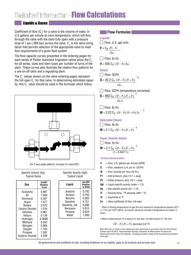
11All general terms and conditions of sale, including limitations of our liability, apply to all products and services sold.
Technical Information - Flow CalculationsLiquids & Gases
Coefficient of flow (Cv) for a valve is the volume of water, in U.S gallons per minute at room temperature, which will flow through the valve with the stem fully open with a pressure drop of 1 psi (.069 bar) across the valve. Cv is the valve sizing factor that permits selection of the appropriate valve to meet flow requirements of a given fluid system
The flow capacity curves presented in the ordering pages for each series of Parker Autoclave Engineers valves show the Cv for all series, sizes and stem types per number of turns of the stem. These curves also illustrate the relative flow patterns for a vee on-off stem and a regulating stem.
The Cv values shown on the valve ordering pages represent the full-open Cv for that valve. In determining estimated capac-ity, this Cv value should be used in the formulas which follow.
LiquidsFlow, U.S. gal./min.
V = Cv √P1 - P2
√SGF
Flow Formulas
Flow, lb./hr.
V = 500 Cv √(P1 - P2) /SGF
GasesFlow, SCFH
Q = 42.2 Cv √(P1 - P2) (P1 + P2)
√SGF
Flow, SCFH (temperature corrected)
Q = 963 Cv √(P1 - P2) (P1 + P2)
√SG TF
Flow, lb./hr.
W = 3.22 Cv √(P1 - P2) (P1 + P2)/ SG
†
†
*†
Saturated SteamFlow, lb./hr.
W = 2.1 Cv √(P1 - P2) (P1 + P2) †
Super Heated SteamFlow, lb./hr.
W = 2.1 Cv √(P1 - P2) (P1 + P2) †
(1 + 0.0007 TS)
Specific Gravity (Sg) Typical Gases
GasSG@RTRelative to Air
Acetylene 0.897 Air 1.000 Ammonia 0.587 Argon 1.377 Butane 2.070 Carbon Dioxide 1.516 Ethylene 0.967 Helium 0.138 Hydrogen 0.0695 Methane 0.553 Nitrogen 0.966 Oxygen 1.103 Propane 1.562 Sulphur Dioxide 2.208
Specific Gravity (Sgf) Typical Liquid
Liquid
Acetone 0.792 Alcohol 0.792 Benzine 0.902 Gasoline 0.751 Gasoline, nat. 0.680 Kerosene 0.815 Pentane 0.624 Water 1.000
Formula Nomenclature
V = Flow, U.S. gallons per minute (GPM)
Q = Flow, standard cu.ft. per hr. (SCFH)
W = Flow, pounds per hour (lb./hr.)
P1 = Inlet pressure, psia (14.7 + psig)
P2 = Outlet pressure, psia (14.7 + psig)
Sgf = Liquid specific gravity (water = 1.0)
Sg = Gas specific gravity (air = 1.0)
Tf = Flowing temp., °R absolute (460 + °F)
Ts = Superheat in °F
Cv = Valve coefficient of flow, full open
* Effect of flowing temperatures on gas flow are minimal for temperatures between 30°F (-1.1°C) and 150°F (66°C). Correction should be included if temperatures are higher or lower. † Where outlet pressure P2 is equal to or less than 1/2 inlet pressure P1, the term:
√(P1 - P2) (P1 + P2) becomes 0.87 P1
Note: Maximum Cv values in this catalog have been determined in accordance with the Fluid Controls Institute report FCI58-2. “Recommended Voluntary Standards for Measurement Procedure for Determining Control Valve Flow Capacity,” including procedure, design of the test stand and evaluation of the data.
SGF@RTRelative to Water
For 2 way angle patterns, increase Cv value 50%
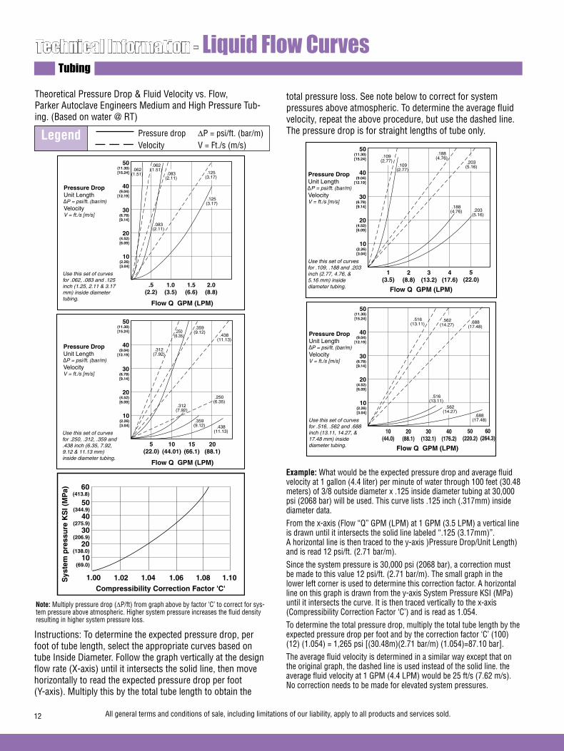
12 All general terms and conditions of sale, including limitations of our liability, apply to all products and services sold.
Technical Information - Liquid Flow CurvesTubing
Theoretical Pressure Drop & Fluid Velocity vs. Flow, Parker Autoclave Engineers Medium and High Pressure Tub-ing. (Based on water @ RT)
Instructions: To determine the expected pressure drop, per foot of tube length, select the appropriate curves based on tube Inside Diameter. Follow the graph vertically at the design flow rate (X-axis) until it intersects the solid line, then move horizontally to read the expected pressure drop per foot (Y-axis). Multiply this by the total tube length to obtain the
Legend Pressure drop ∆P = psi/ft. (bar/m)Velocity V = Ft./s (m/s)
Pressure DropUnit Length P = psi/ft. (bar/m)Velocity V = ft./s [m/s]
Use this set of curves for .062, .083 and .125 inch (1.25, 2.11 & 3.17 mm) inside diameter tubing.
Flow Q GPM (LPM)
50(11.30)[15.24]
.5(2.2)
.062(1.51)
40(9.04)
[12.19]
30(6.78)[9.14]
20(4.52)[6.09]
10(2.26)[3.04]
1.0(3.5)
1.5(6.6)
2.0(8.8)
.062(1.51)
.083(2.11)
.083(2.11)
.125(3.17)
.125(3.17)∆
Pressure DropUnit Length P = psi/ft. (bar/m)Velocity V = ft./s [m/s]
Use this set of curves for .250, .312, .359 and .438 inch (6.35, 7.92, 9.12 & 11.13 mm) inside diameter tubing.
Flow Q GPM (LPM)
50(11.30)[15.24]
5(22.0)
40(9.04)
[12.19]
30(6.78)[9.14]
20(4.52)[6.09]
10(2.26)[3.04]
10(44.01)
15(66.1)
20(88.1)
.250(6.35)
.438(11.13)
.312(7.92)
.359(9.12)
.438(11.13)
.359(9.12).250
(6.35)
.312(7.92)
∆
Pressure DropUnit Length P = psi/ft. (bar/m)Velocity V = ft./s [m/s]
Use this set of curves for .109, .188 and .203 inch (2.77, 4.76, & 5.16 mm) inside diameter tubing. Flow Q GPM (LPM)
50(11.30)[15.24]
1(3.5)
40(9.04)
[12.19]
30(6.78)[9.14]
20(4.52)[6.09]
10(2.26)[3.04]
2(8.8)
3(13.2)
4(17.6)
.203(5.16)
.188(4.76).109
(2.77)
5(22.0)
.109(2.77)
.188(4.76) .203
(5.16)
∆
Pressure DropUnit Length P = psi/ft. (bar/m)Velocity V = ft./s [m/s]
Use this set of curves for .516, .562 and .688 inch (13.11, 14.27, & 17.48 mm) inside diameter tubing. Flow Q GPM (LPM)
50(11.30)[15.24]
10(44.0)
40(9.04)
[12.19]
30(6.78)[9.14]
20(4.52)[6.09]
10(2.26)[3.04]
20(88.1)
30(132.1)
40(176.2)
50(220.2)
.562(14.27)
.688(17.48)
60(264.3)
.516(13.11)
.516(13.11)
.562(14.27)
.688(17.48)
∆
60(413.8)
50(344.9)
40(275.9)
30(206.9)
20(138.0)
10(69.0)
1.00 1.02 1.04 1.06 1.08 1.10Compressibility Correction Factor 'C'
Sys
tem
pre
ssu
re K
SI (
MP
a)
Example: What would be the expected pressure drop and average fluid velocity at 1 gallon (4.4 liter) per minute of water through 100 feet (30.48 meters) of 3/8 outside diameter x .125 inside diameter tubing at 30,000 psi (2068 bar) will be used. This curve lists .125 inch (.317mm) inside diameter data.From the x-axis (Flow “Q” GPM (LPM) at 1 GPM (3.5 LPM) a vertical line is drawn until it intersects the solid line labeled “.125 (3.17mm)”. A horizontal line is then traced to the y-axis )Pressure Drop/Unit Length) and is read 12 psi/ft. (2.71 bar/m).Since the system pressure is 30,000 psi (2068 bar), a correction must be made to this value 12 psi/ft. (2.71 bar/m). The small graph in the lower left corner is used to determine this correction factor. A horizontal line on this graph is drawn from the y-axis System Pressure KSI (MPa) until it intersects the curve. It is then traced vertically to the x-axis (Compressibility Correction Factor ‘C’) and is read as 1.054. To determine the total pressure drop, multiply the total tube length by the expected pressure drop per foot and by the correction factor ‘C’ (100) (12) (1.054) = 1,265 psi [(30.48m)(2.71 bar/m) (1.054)=87.10 bar].The average fluid velocity is determined in a similar way except that on the original graph, the dashed line is used instead of the solid line. the average fluid velocity at 1 GPM (4.4 LPM) would be 25 ft/s (7.62 m/s). No correction needs to be made for elevated system pressures.
Note: Multiply pressure drop (∆P/ft) from graph above by factor ‘C’ to correct for sys-tem pressure above atmospheric. Higher system pressure increases the fluid density resulting in higher system pressure loss.
total pressure loss. See note below to correct for system pressures above atmospheric. To determine the average fluid velocity, repeat the above procedure, but use the dashed line. The pressure drop is for straight lengths of tube only.

13All general terms and conditions of sale, including limitations of our liability, apply to all products and services sold.
Technical Information - Conversion Tables
0 -18 460 255 32 0 492 273 -460 -273 0 0
Temperature Equivalents
Fahrenheit °F Celcius °C Rankine°R Kelvin°KDegrees Fahrenheit = °F
Degrees Celcius = 5/9 (°F - 32)
Degrees Kelvin = °C + 273.15
Degrees Rankine = °F + 459.67
Linear Equivalents
foot inch meter centimeter millimeter micron angstrom
Pressure Equivalents Pa MPa atm bar kg/cm2 psi inches Hg Microns Hg
1 35.31 264.2 1000 1056.8 61023 1x10⁶
28.317x10⁻³ 1 7.4822 28.317 29.92 1728 28.317x10³
3.785x10⁻³ 0.1337 1 3.785 4 231 3785 1x10⁻³ 0.03531 0.2642 1 1.057 61.023 1000 9.463x10⁻⁴ 0.03342 0.25 0.9463 1 57.75 946.25 1.638x10⁻⁵ 5.787x10⁻⁴ 43.29x10⁻⁴ 0.01639 0.01732 1 16.387 1x10⁻⁶ 35.31x10⁻⁶ 2.642x10⁻⁴ 1x10⁻³ 10.568x10⁻⁴ 0.06102 1
Volume Equivalents
meter3 foot3 gallon* liter quart inch3 cc
1 1728 231 27.68x10³ 27.6797 5.787x10⁻⁴ 1 0.1337 16.018 0.01602 4.33x10⁻³ 7.48 1 119.8257 0.11983 3.613x10⁻⁵ 0.06243 8.3445x10⁻³ 1 .001 0.03613 62.43 8.3445 1000 1
Density Equivalents
pound/inch3 pound/ft3 kg/meter* pound/gallon3 gram/cm3
1 0.01667 0.1337 2.228x10⁻³ 3.7848 0.06308 63.08 60 1 8.022 0.1337 227.1 3.7848 3784.8 7.48 0.1247 1 0.01667 28.32 0.472 472 448.8 7.48 60 1 1698.6 28.32 28.32x10³
0.26418 4.403x10⁻³ 0.03531 5.886x10⁻⁴ 1 0.01667 16.67 15.8502 264.18x10⁻³ 2.11887 0.03531 60 1 1000 .01585 264.2x10⁻⁶ 2.1187x10⁻³ 35.3145x10⁻⁶ .06 0.001 1
Fluid Flow Equivalents
*gal/hr *gal/min cu ft/hr cu ft/min liters/hr liters/min cc/min
*U.S. Gallons
*U.S. Gallons
*U.S. Gallons
PSIG = lb./in.2 Gage
PSIG = lb./in.2 absolute
PSIA = PSIG plus atmospheric pressure
1Torr = 133.322Pa
US. gallon = 0.833 British Imperial gallon
British Imperial gallon = 1.201 US. gallon
US. gallon water = 8.345 pounds
British Imperial gallon water= 10.022 pounds
US. fluid ounce = 29.573 centimeters3
British Imperial fluid ounce = 28.413 centimeters3
1 1x10⁻⁶ 9.8692x10⁻⁶ 1x10⁻⁵ 1.0197x10⁻⁵ 1.4504x10⁻⁴ 2.9530x10⁻⁴ 7.50059 1x10⁻⁶ 1 9.8692 10 10.1971 145.04 295.30 7.5006x10⁶
101325 0.101325 1 1.01325 1.0332 14.696 29.921 760x103
100000 0.1 0.98692 1 1.01971 14.504 29.53 750.059x10³
98066.5 0.098067 0.96784 0.98067 1 14.223 28.959 735.56x10³
6894.757 6.8948x10⁻³ 0.06805 0.06895 0.07031 1 2.036 51.715x10⁶
3386.389 3.3864x10⁻³ 0.03342 0.03386 0.03453 0.49116 1 2.54x10⁴
0.133322 1.3332x10⁻⁷ 1.3158x10⁻⁶ 1.3332x10⁻⁶ 1.3595x10⁻⁶ 19.337x10⁻⁶ 39.37x10⁻⁶ 1
1 12 0.3048 30.48 304.800 3.048x10⁵ 3.048x10⁹
0.08333 1 0.0254 2.54 25.4 2.54x10⁴ 2.54x10⁸
3.28083 39.37 1 100 1000 1x10⁶ 1x10¹⁰
0.03281 0.3937 0.01 1 10 1x10⁴ 1x10⁸
3.281x10⁻³ 0.03937 0.001 0.1 1 1000 1x10⁷
3.281x10⁻⁶ 3.937x10⁻⁵ 1x10⁻⁶ 1x10⁻⁴ 1x10⁻³ 1 1x10⁴
3.281x10⁻¹⁰ 3.937x10⁻⁹ 1x10⁻¹⁰ 1x10⁻⁸ 1x10⁻⁷ 1x10⁻⁴ 1

14 All general terms and conditions of sale, including limitations of our liability, apply to all products and services sold.
Technical Information - Conversion Tables Area Equivalents
ft2 in2 m2 cm2 mm2
1 16 .45351 453.592 7000 0.0625 1 .02836 28.345 437.5 2.205 35.27 1 1000 15.435x10³
2.205x10⁻³ 0.03527 0.001 1 15.435 1.428x10⁻⁴ 0.002285 64.8x10⁻⁶ 0.0648 1
Weight Equivalents
pound ounce kilogram gram grain
Power Equivalents
kilowatt horsepower* ft lbs/sec ft lbs/min ft lbs/hr Btu/sec Btu/min Btu/hrUS. horsepower = 1.014 metric horse-power
Metric. horsepower = 0.986 US. horse-power
Work or Energy Equivalents kilowatt- horsepower* foot- inch- Btu kilogram- kilogram- joules hours hours pounds pounds meters calories Newton meters
1 0.01 0.6 0.036 0.03281 1.9685 0.02237 100 1 60 3.6 3.281 196.85 2.2369 1.667 0.01667 1 0.06 0.05468 3.281 .03728 27.78 0.2778 16.67 1 0.91134 54.681 0.62137 30.48 0.3048 18.29 1.0973 1 60 0.68182 0.508 508x10-3 0.3048 0.01829 0.01667 1 0.01136 44.704 0.44704 26.82 1.6093 1.4667 88 1
Velocity Equivalents
cm/sec meter/sec meter/min kilometer/hr feet/sec feet/min mile/hr
*U.S. Horsepower
*U.S. Horsepower
Statute mile/hour = .8684 knot
Knot = 1.1516 mile/hour = 1.689 feet/second
1 Statue Mile = 5280 feet
1 Nautical Mile = 6076 feet
1 144 0.09291 929.034 9.29x10⁴
6.944x10⁻³ 1 6.451x10⁻⁴ 6.4516 645.1625 10.7639 1550 1 1x10⁻⁴ 1x10⁶
1.0764x10⁻³ 0.155 1x10⁻⁴ 1 100 1.076x10⁻⁵ 1.55x10⁻³ 1x10⁻⁶ .01 1
1 1.341 738 44.280 2.653x10⁶ 0.948 56.9 3413 .7457 1 550 33x103 1.99x10⁶ 0.707 42.41 25.44 13.55x10⁻⁴ 18.18x10⁻⁴ 1 60 3600 12.84x10⁻⁴ 0.0771 4.62 22.59x10⁻⁶ 0.303x10⁻⁴ 0.01667 1 60 21.41x10⁻⁶ 12.84x10⁻⁴ 0.0771 0.376x10⁻⁶ 0.505x10⁻⁶ 2.78x10⁻⁴ 0.01667 1 0.357x10⁻⁶ 21.41x10⁻⁶ 12.84x10⁻⁴
1.055 1.416 778 46.7x10³ 2.802x10⁻⁶ 1 60 3600 0.01759 0.02359 12.98 778 46.7x10³ 0.01667 1 60 2.925x10⁻⁴ 3.933x10⁻⁴ 0.2163 12.98 778 2.778x10⁻⁴ 0.01667 1
1 1.342 2.655x10⁶ 31.86x10⁶ 3415 367.1x10³ 860.238 3.6x10⁶
.7457 1 1.98x10⁶ 23.76x10⁶ 2546.5 273.546x10³ 641.477 2.685x10⁶
0.376x10⁻⁶ 0.505x10⁻⁶ 1 12 1.286x10⁻³ 0.13826 3.239x10⁻⁴ 1.3562 0.313x10⁻⁷ 0.458x10⁻⁷ 0.08333 1 0.107x10⁻³ 11.522x10⁻³ 0.27x10⁻⁴ 0.11302 2.928x10⁻⁴ 3.929x10⁻⁴ 778 9336 1 107.5 0.2519 1054.8 2.717x10⁻⁶ 3.653x10⁻⁶ 7.233 86.796 9.302x10⁻³ 1 23.43x10⁻⁴ 9.804 1.161x10⁻³ 1.558x10⁻³ 3088.26 37059.12 3.9683 427.32 1 4189.48 2.774x10⁻⁷ 3.7229x10⁻⁷ 0.7373 8.8476 9.478x10⁻⁴ 0.10194 2.39x10⁻⁴ 1

15All general terms and conditions of sale, including limitations of our liability, apply to all products and services sold.
Technical Information - Pressure vs. Bend RadiusTubing
Allowable Pressure vs. Bend (Mandrel) Radius
Parker Autoclave Engineers Medium & High Pressure tubing (316 & 304 SS)
Parker Autoclave Engineers Ultra High Pressure tubing (316SS)
MAW
P ps
i x 1
000
(bar
x 1
000)
@ R
T
Mandrel Radius (inches)0 2 4 6 8 10 12 14 16 18 20 22 24 26 28
150(10.34)
150,000 psi tubing(10342 bar)
149(10.27)
148(10.20)
147(10.13)
146(10.06)
145(9.99)
Mandrel radius(Rm)
60,000 and 100,000 psi (4137 & 6895 bar)High Pressure Tubing Size Rm (min.) Inches inches (mm)1 1/4 x .083 1.25 (31.8)2 3/8 x .125 1.75 (44.5)3 9/16 x .188 2.625 (66.7)
40,000 psi (2758 bar)High Pressure Tubing
43,000 psi (2965 bar)High Pressure Tubing Size Rm (min.) Inches inches (mm) 1 x .438 4.625 (117.5)
20,000 psi (1379 bar)Medium Pressure Tubing
150,000 psi (10342 bar)Ultra High Pressure Tubing Size Rm (min.) Inches inches (mm) 5/16 x 1/16 6 (152.4)
15,000 psi (1034 bar) Medium Pressure Tubing Size Rm (min.) Inches inches (mm)1 9/16 x .359 2.625 (66.7)2 3/4 x .516 3.5 (89.9)3 1 x .688 4.625 (117.5)4 1 1/2 x .938 4.50 (114.3)
0 1 2 3 4 5 6 7 8 9 10 11 12 13 14
14,000(9.6)
15,000(1034)
19,000(13.0)
20,000(13.8)
39,000(26.9)
40,000(27.6)
58,000(40.0)
59,000(40.7)
60,000(41.4)
MA
WP
psi
x (
bar
x 10
0) @
RT
Mandrel Radius (inches)
60,000 psi (4137 bar)high pressure tubing
41,000(28.3)
43,000 psi (2965 bar)high pressure tubing
20,000 psi (1379 bar)medium pressure tubing
15,000 psi (1034 bar)medium pressure tubing
1
2 3
1
2
1
23 4 5
12 3
40,000 psi (2756 bar)high pressure tubing
42,000(29.0)
43,000(29.6)
Size Rm (min.) Inches inches (mm)1 1/4 x .109 1.25 (31.8)2 3/8 x .203 1.75 (44.5)3 9/16 x .312 2.625 (66.7)4 3/4 x .438 3.5 (89.9)5 1 x .562 4.625 (117.5)
Size Rm (min.) Inches inches (mm)1 9/16 x .250 2.625 (66.7)2 9/16 x .312
(Curved not shown)

02-0142SE January2013© 2013 Parker Hannifin Corporation | Autoclave Engineers is a registered trademark of the Parker Hannifin Corporation
Parker Hannifin Manufacturing Ltd. Instrumentation Products Division, Europe Industrial Estate WhitemillWexford, Republic of IrelandPH: 353 53 914 1566FAX: 353 53 914 1582
Instrumentation Products DivisionAutoclave Engineers Operation8325 Hessinger DriveErie, Pennsylvania 16509-4679 USAPH: 814-860-5700 FAX: 814-860-5811www.autoclave.com
WARNING
FAILURE, IMPROPER SELECTION OR IMPROPER USE OF THE PRODUCTS AND/OR SYSTEMS DESCRIBED HEREIN OR RELATED ITEMS CAN CAUSE DEATH, PERSONAL INJURY AND PROPERTY DAMAGE.This document and other information from Parker Hannifin Corporation, its subsidiaries and authorized distributors provide product and/or system options for further investigation by users having technical expertise. It is important that you analyze all aspects of your application and review the information concerning the product or system in the current product catalog. Due to the variety of operating conditions and applications for these products or systems, the user, through its own analysis and testing, is solely responsible for making the final selection of the products and systems and assuring that all performance, safety and warning requirements of the application are met. The products described herein, including without limitation, product features, specifications, designs, availability and pricing, are subject to change by Parker Hannifin Corporation and its subsidiaries at any time without notice.
Offer of Sale
The items described in this document are available for sale by Parker Hannifin Corporation, its subsidiaries or its authorized distributors. Any sale contract entered by Parker will be governed by the provisions stated in Parker's standard terms and conditions of sale (copy available upon request).
ISO-9001 Certified
Caution! Do not mix or interchange parts or tubing with those of other manufacturers. Doing so is unsafe and will void warranty.
Caution! Parker Autoclave Engineers Valves, Fittings and Tools are not designed to work with common commercial instrument tubing and will only work with tubing built to Parker Autoclave Engineers AES Specifications. Failure to do so will void warranty.
VFTLubrication GuideVFTLubrication Guide
General Information
For reliable operation and long life of hand valves, air valves, relief valves, check valves and safety heads, Autoclave Engineers strongly recommends proper lubrication of all components that are subject to friction dur-ing assembly and /or operation. This is especially important where metal to metal contact occurs such as on connection gland threads, packing gland threads and stem threads. Without proper lubrication, the high loads imposed on these threads may cause the parts to weld (or gall) together from the high metal to metal contact forces and friction heat. Lubrication is also essential for the effective sealing and long life of o-rings, especially those that are used in dynamic sealing applications. The performance of metal to metal seals will be improved with lubrication but, they do not absolutely require it.
Lubricant selection is strongly dependent on the application of the given component. Process fluids, fluid tem-perature, ambient environment temperature, materials and other factors are important in selecting a lubricant. This manual gives some basic guidelines in the proper selection and application of lubricants. The end user must ultimately determine the suitability of a lubricant based on process requirements.
Note: Autoclave Engineers assumes no liability in selecting lubricant for customer applications.
Autoclave Engineers reserves the right to alter the specifications given in this publication in line with our policy of continuous improve-ment.
All general terms and conditions of sale, including limitations of our liability, apply to all products and services sold.
Caution: While testing has shown o-rings to provide satisfactory service life, both cyclic and shelf life may vary widely with differing service conditions, properties of reactants, pressure and temperature cycling, and age of the o-ring. Frequent inspection should be made to detect any deterioration and o-rings replaced as required.ISO-9001 Certified

Lubrication Sites
1. Speedbite, Slimline and High PressureConnections in all valves and fittings - Prior to assembly, the connection gland should be lubricated on the threads and on the area that is in contact with the sleeve or collar. AE provides as standard a dry molybdenum disulfide lubricant on Speedbite glands unless specified otherwise. If process tolerable, a small amount of any lubricant (or process fluid) on the end of the tube cone or connection sleeve will help to maximize the metal-to-metal sealing process. This inherently provides for better sealing of gases.
2. Hard Valves - Ideally, the non-rotating stem should be lubricated along the shank that fits into the threaded stem sleeve as well as on the surfac-es that are in contact with the stem washers. The threaded stem sleeve should be lubricated on the stem threads and at the ends (see Figure 1). The packing gland should be lubricated on the external threads and on the end that is in contact with the packing washer. For valves with replacement seats, the external threads on the seat retainer and the portion of the seat retainer in contact with the seat should be lubricated.
3. Air Valves - The packing gland and seat retainer (if the valve has a replaceable seat) should be lubricated in the same manner as the hand valve. Threads should also be lubricated on all of the yoke screws (for yoke style valves) and on the retainer insert (on other air operated valves).
For piston type air operators, o-ring lubricant should be applied to the inside of the operator housing, on the center rod and on all the o-rings, on the pistons and divider plates. On air-to-open diaphragm operators, the o-ring on the stem should be lubricat-ed. The threads and end of the spring adjustment screw should be lubricated on all air-to-open valves. Refer to Figure 2 and 3 for lubrication sites on piston and diaphragm style operators.
4. Check Valves - The gland nut should be lubricated on the external threads and at the end where it contacts the cover. The cover should be lubricated at the sealing surface where it contacts the body. For o-ring check valves, a small amount of o-ring lubricant on the o-ring will help swell the elas-tomer and aid sealing. Refer to Figure 4 for lubrica-tion sites on check valves.
5. Relief Valves - Threads should be lubricated on the cap, spring cylinder, adjustment bolt and on the seat gland. Refer to Figure 5 for lubrication sites on the relief valve.
6. Safety Heads - The threads and end of the hold down nut should be lubricated. Refer to figure 6 for lubrication sites on the safety head.
For any part not covered in the above statements, the general rule is that parts that will move against each other during assembly or operation should be lubricated at the points/areas of contact.
Figure 2Air Valve PistonLubrication Sites
Metal to MetalLubricant
O-ringLubricant
Metal to MetalLubricant
Metal to MetalLubricant
(If not MoS2{dry} film coated)
Metal to MetalSeal Surface
Lubricant
Figure 1Hand Valve
Lubrication Sites

1. Jet Lube SS-301 - This lubricant consists of pure copper flakes that are homogenized into a non-melting, nonvolatile viscous carrier. It is fortified with anti-oxidants, rust and corrosion inhibitors. Jet Lube SS-30 is the standard lubricant for Autoclave VFT components with sliding metal to metal con-tact surfaces. The surfaces are copper coated and prevents seizure, galling and heat freeze. SS-30 comes in the form of a thick oil that can be eas-ily brushed on the surfaces to be lubricated. The absolute service temperature range is form 0 to 1800ºF. Jet Lube SS-30 is not recommended for extreme low temperature applications or processes that will not tolerate the presence of copper.
2. Jet Lube MP-50 Moly Paste1 - This is a thick paste that contains molybdenum disulfide (MoS). This lubricant is suitable for preventing seizure and galling of parts at absolute temperatures of -300ºF to 750ºF. It is recommended for metal to metal components that are exposed to temperatures of less than 0ºF. Other lubricants may solidify under these conditions and prevent the effective opera-tion of dynamic components.
3. DuPont Krytox 240AC2 - Krytox is a non-flam-mable fluorinated grease used for metal to metallubrication in valves that are cleaned and desig-nated for oxygen service. It comes in the form of a white grease and has a recommended absolute service temperature range of -15 to 500ºF.
4. Hallocarbon 25-5S - This is a silica thickened chlorotrifluorethylene grease that is recommended for use on check valve balls and o-rings. It is not recommended for use on magnesium and aluminum alloys and in contact with sodium potassium, amines, liquid flurine and liquid chlorine trifluoride. It has a recommended absolute service temperature range of 0 to 350ºF.
5. Neolube DAG 1563 - This is a dry film lubricant for valves used in Navy Nuclear service. It consists of graphite particles in a thermoplastic resin and ispropanol and meets Military Specification MIL-L-24131B. The dry film form allows tight control of impurities that are required for these applications. It has an absolute service temperature of -100 to 400ºF.
6. Dow Corning Molycoat 55M4 - This grease is used for dynamic lubrication between rubber and metal parts in pneumatic systems such as piston style air operators. It is a silicone based lubricant and meets Military Specifications MIL-G-4343. It is not recommended for use on silicone rubber o-rings and seals. It has a recommended absolute service temperature range of -85 to 350ºF.
Figure 3Air Valve (Diaphragm)
Lubrication Sites
Figure 4Check Valve
Lubrication Sites
Recommended Lubricants
Note: This information is provided for reference only. The manufacture of the lubricant should be contacted for specific information based on your application. Refer to the material safety data sheets for information on safe usage and storage methods for these lubricants.
Metal to MetalLubricant
Metal to MetalLubricant
O-ring Lubricant
Metal to MetalLubricant
O-ring Lubricant

02-0027BE-0304
ISO-9001 CertifiedIndustrial EstateWhitemill-WexfordRepublic of IrelandPH: 353-53-41566 FAX: 353-53-41582e-mail: [email protected]
8325 Hessinger DriveErie, Pennsylvania 16509-4679 USAPH: 814-838-5700 FAX: 814-838-5811e-mail: [email protected]
All general terms and conditions of sale, including limitations of our liability, apply to all products and services sold.
! WARNING !
FAILURE OR IMPROPER SELECTION OR IMPROPER USE OF THE PRODUCTS AND/OR SYSTEMS DESCRIBED HEREIN OR RELATED ITEMS CAN CAUSE DEATH, PERSONAL INJURY AND/OR PROPERTY DAMAGE.
This document and other information from Snap-tite, Inc., its subsidiaries and authorized distributors, provides product and/or system options for further investigation by users having technical expertise. It is important that you analyze all aspects of your application and review the information concerning the product or system in the current product catalog. Due to the variety of operation conditions and applications for these products or systems, the user, through its own
analysis and testing, is solely responsible for making the final selection of the products and systems and assuring that all performance, safety and warning requirements of the application are met. The products described herein, including without limitation, product features, specifications, designs, availability and pricing, are subject to change by Snap-tite, Inc. and its subsidiaries at any time without notice.
For service, contact the Autocalve Engineers’ Representative in you area, or FAX Autoclave Engineers’ Cus-tomer Support Services at 1-814-860-5703.
Lubricant Selection Chart
Lubricant Application Absolute Service Temperature Range
Jet-Lube SS-30 Metal to Metal, Standard Application 0ºF to 1800ºF (-18ºC to 982ºC)
Jet-Lube Moly Paste MP-50 Metal to Metal, Low Temperature Application -300ºF to 750ºF (-185ºC to 398ºC)
Krytox 240 AC Metal to Metal, Oxygen Clean Components -15ºF to 500ºF (-26ºC to 260ºC)
Hallocarbon 25-5S Check Valve Ball and Poppet Lubricant 0ºF to 350ºF (-18ºC to 177ºC)
Neolube DAG 156 Metal to Metal, Nuclear Service -100ºF to 400ºF (-73ºC to 204ºC)
Dow Corning M55 Dynamic O-ring Seals -85ºF to 350ºF (-65ºC to 177ºC)
Notes: Specific applications may require other service temperature ranges. 1SS-30 and MP-50 Moly Paste are registered trademarks of Jet Lube Inc. 2Krytox is a registered trademark of E.I.duPont de Nemours & Co., Inc. 3DAG is a registered trademark of Acheson Industries, Inc. 4Molycoat and Dow Corning are registered trademarks of Dow Corning Corp.
Figure 5Relief Valve
Lubrication Sites
Figure 6Safety Head
Lubrication Sites
Metal to Metal Lubricant
Metal to MetalSeal Surface Lubricant
Metal to MetalLubricant
Services
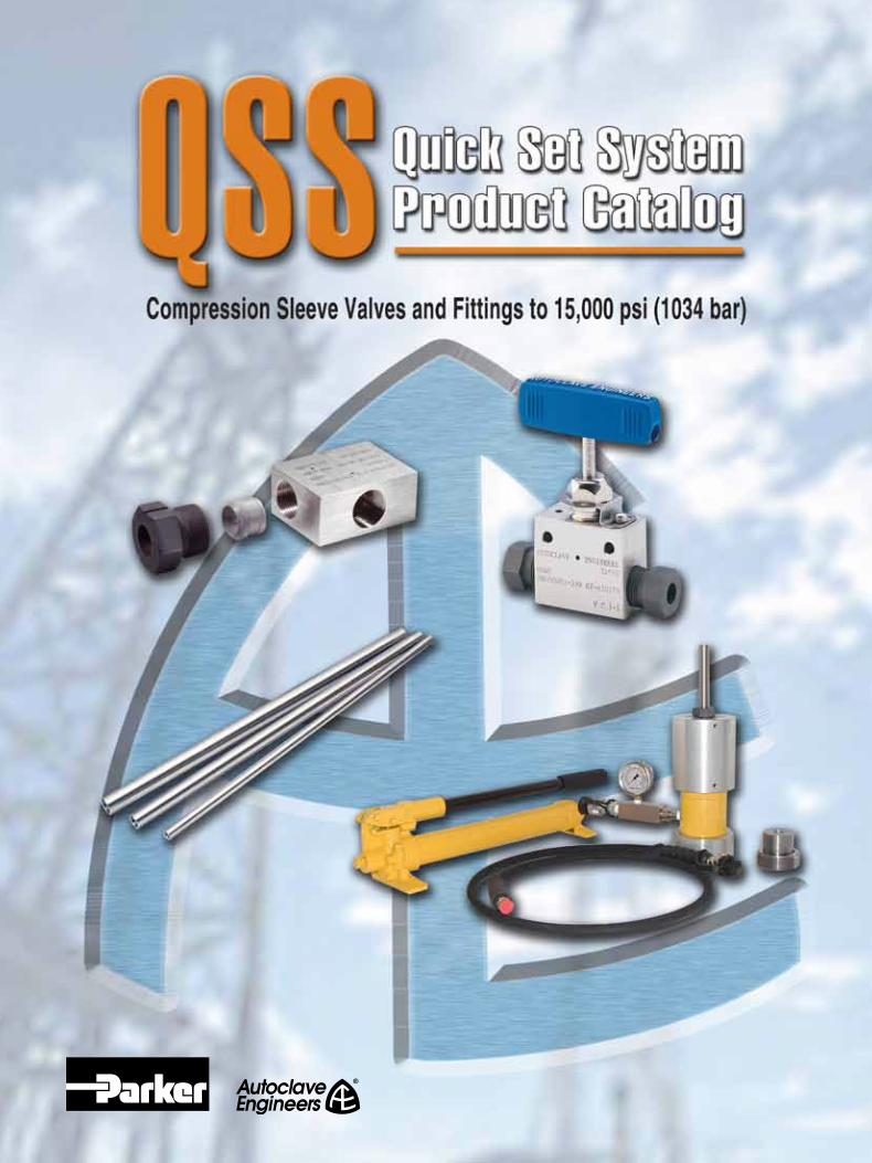

22
This page left blank

3
QSS-Quick Set SystemIndex
QSS - Index
3
QSS Introduction .................................. 4-5
QS Valves .......................................... 7-9• 1/4", 3/8", 9/16" and 3/4", Pressures to 15,000 psi (1034 bar)
QS Ball Valves and Actuators ................ 11-30• 2 and 3 Way Ball Valves
QS Fittings and Tubing ........................ 31-36• 1/4", 3/8", 9/16" and 3/4", Pressures to 15,000 psi (1034 bar)• Elbows, Tees, Crosses, Couplings and Bulkhead Adapters• Tubing and Nipples• Check Valves
QS Adapters .................................... 37-43 • Male to Female
QSS Tools, Installation, Operation and Maintenance.................................... 44-47 • QSS Assembly Procedure
• Hydraulic Sleeve Set Tool

Parker Autoclave Engineers, the recog-nized world leading designer and manu-facturer of high pressure equipment up to 150,000 psi (10342 bar), has engineered an advanced single ferrule fitting system called the QSS-Quick Set System. This 1/4” through 3/4” O.D. heavy-walled, high flowing tubing system operates in all sizes up to 15,000 psi (1034 bar).
The single compression sleeve design will provide leak free, vibration resistant ser-vice from 0° to 650°F (-17.8° to 343°C). Its design reduces the risk of lost parts and incorrect installation common with the more complex 2-ferrule conceptions and is much easier to handle, reducing assembly errors.
In certain applications, this ferrule style fitting may be an advantage for your installation. With only a wrench needed for the smaller sizes and a hydraulic set tool for the larger sizes, no special train-ing or knowledge is needed to create safe, re-settable tube end connections.
Safe, Reliable, Cost Effective…QSS-Quick Set System
4
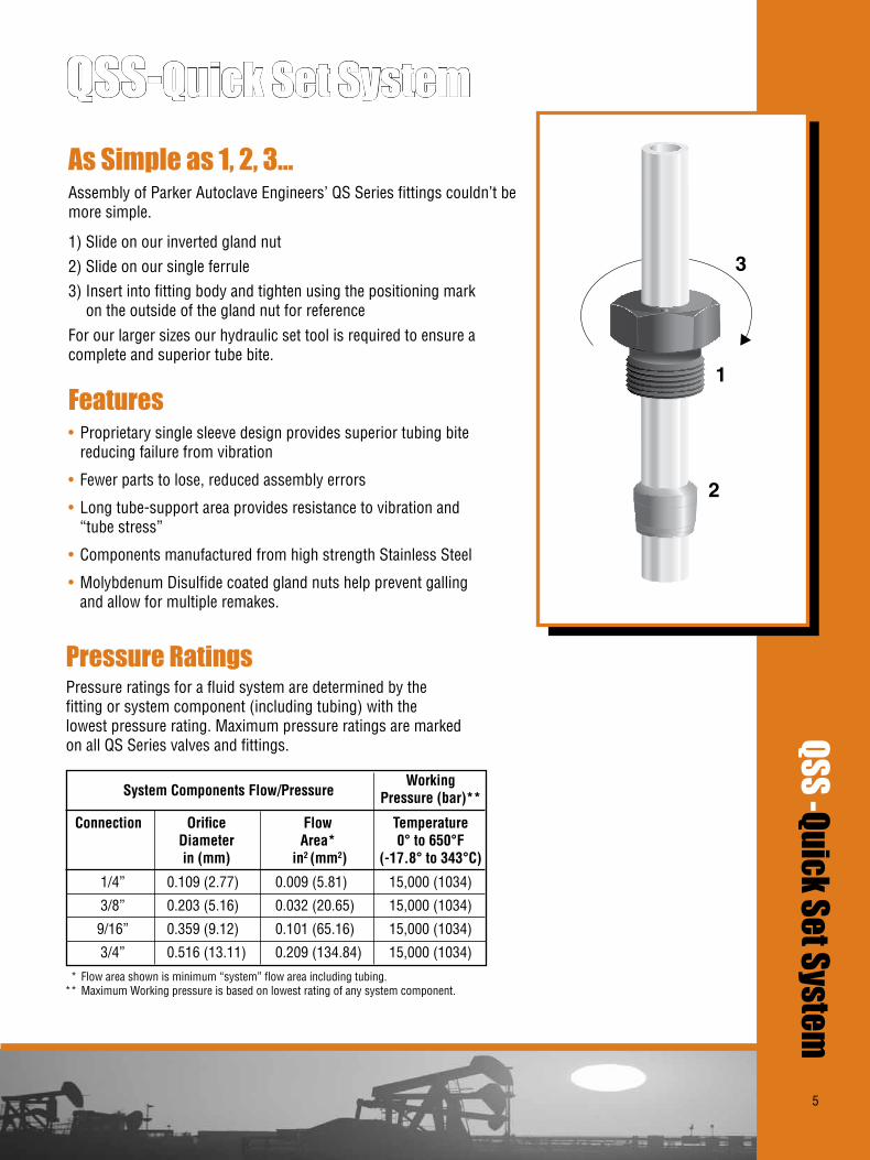
QSS -Quick Set System
1
2
3
As Simple as 1, 2, 3…Assembly of Parker Autoclave Engineers’ QS Series fittings couldn’t be more simple.
1) Slide on our inverted gland nut2) Slide on our single ferrule3) Insert into fitting body and tighten using the positioning mark on the outside of the gland nut for referenceFor our larger sizes our hydraulic set tool is required to ensure a complete and superior tube bite.
• Proprietary single sleeve design provides superior tubing bite reducing failure from vibration
• Fewer parts to lose, reduced assembly errors
• Long tube-support area provides resistance to vibration and “tube stress”
• Components manufactured from high strength Stainless Steel
• Molybdenum Disulfide coated gland nuts help prevent galling and allow for multiple remakes.
Features
Pressure RatingsPressure ratings for a fluid system are determined by the fitting or system component (including tubing) with the lowest pressure rating. Maximum pressure ratings are marked on all QS Series valves and fittings.
1/4” 0.109 (2.77) 0.009 (5.81) 15,000 (1034)
3/8” 0.203 (5.16) 0.032 (20.65) 15,000 (1034)
9/16” 0.359 (9.12) 0.101 (65.16) 15,000 (1034)
3/4” 0.516 (13.11) 0.209 (134.84) 15,000 (1034)
QSS-Quick Set System
Working Pressure (bar)**
Connection Orifice Flow Temperature Diameter Area* 0°to650°F in(mm) in2 (mm2) (-17.8°to343°C)
SystemComponentsFlow/Pressure
* Flow area shown is minimum “system” flow area including tubing. ** Maximum Working pressure is based on lowest rating of any system component.
5

6
This page left blank

7
Needle Valves
Pressures to 15,000 psi (1034 bar)
QS Series
Since 1945 Parker Autoclave Engineers has designed and built premium quality valves, fittings and tubing. This commitment to engineering and manufacturing excellence has earned Parker Autoclave Engineers a reputation for reliable efficient product performance. Parker Autoclave Engineers has long been established as the world leader in high pressure fluid handling components for the chemical/petrochemical, waterblast, research, and oil and gas industries.
Medium Pressure Valve Features:
• Compression Sleeve to 15,000 psi (1034 bar).
• Tubing sizes available from 1/4” to 3/4”.
• Rising stem/barstock body design.
• Non-rotating stem prevents stem/seat galling.
• Anti-galling molybdenum disulfide coated gland nuts.
• Gland nut positioning mark for assembly.
• Connection weep holes for safety and leak detection.
• Metal-to-metal seating achieves bubble-tight shut-off, longer stem/seat life in abrasive flow, greater durability for repeated on/off cycles and excellent corrosion resistance.
• PTFE (Teflon) encapsulated packing provides dependable stem and body sealing.
• Stem sleeve and packing gland materials have been selected to achieve extended thread cycle life and reduced handle torque.
• Choice of Vee or Regulating stem tip.
• Available in two body patterns.
Parker Autoclave Engineers valves are complemented by a complete line of fittings, tubing, check valves and line filters. The QS Series uses Parker Autoclave Engineers’ Quick Set compression sleeve design, providing fast easy make-up and reliable bubble-tight performance in liquid or gas service.
Needle Valves - QS SeriesMedium
Pressure
Medium Pressure
7

8
Pressures to 15,000 psi (1034 bar)
Pressure/ Tube Temperature Outside Rating Diameter Orifice psi(bar) Size Connection Size Rated @Room Inches Type Inches(mm) Cv* Temperature** 1/4 QS 250 0.125 (3.18) 0.31 15,000 (1034) 3/8 QS 375 0.219 (5.56) 0.75 15,000 (1034) 9/16 QS 562 0.359 (9.12) 2.80 15,000 (1034) 3/4 QS 750 0.516 (13.10) 5.20 15,000 (1034) Notes:
* CV values shown are for 2-way straight valve pattern. For 2-way angle patterns, increase CV value 50%. (Based on water)
** For complete temperature ratings see pressure/temperature rating guide in Technical Information section.
Needle Valves - QS Series
To ensure proper fit use Parker Autoclave Engineers tubing
Ordering ProcedureFor complete information on available stem types, optional connections and additional valve options, see Needle Valve Options section or contact your Sales Representative. QS Series valves are furnished complete with connection components, unless otherwise specified.
Typical catalog number: 15QS4071
Generalized Flow Coefficient Curves (Cv)
% of rated Cv
Num
ber
of tu
rns
open
10 20 30 40 50 60 70 80 90 100
7
6
5
4
3
2
1
0
Regulating Stem
Vee Stem
4-1/4”6-3/8”9-9/16” 12-3/4”
07- non-rotating Vee stem (on-off service)08- non-rotating regulating stem (tapered tip for regulating and shutoff)87 - Vee stem with replaceable seat88 - Regulating stem with replaceable seat
1 - two-way straight2 - two-way angle3- three-way, two on pressure4- three-way, one on pressure5- three-way, two stem manifold valve
For extreme temperature and other
options, see Valve Options.
OptionsOptions
1Body
Pattern
07Stem/SeatType
4OutsideDiameterTubeSize
15QSValveSeries
15QS
LOCKING DEVICE
ADJUSTABLE PACKING BELOW THREADS
METAL-TO-METAL SEATING
CHOICE OF VEE OR REGULATING STEM TIP
COLD WORKED TYPE 316 SS BODY IN FIVE PATTERNS
ANTI-EXTRUSION BACK-UP RINGS
LOW FRICTION ALUMINUM BRONZE PACKING GLAND
ONE PIECE NON-ROTATINGSTEM
POWDER COATEDSTAINLESS STEELHANDLE
MEDIUM PRESSURE COMPRESSION SLEEVE CONNECTIONS
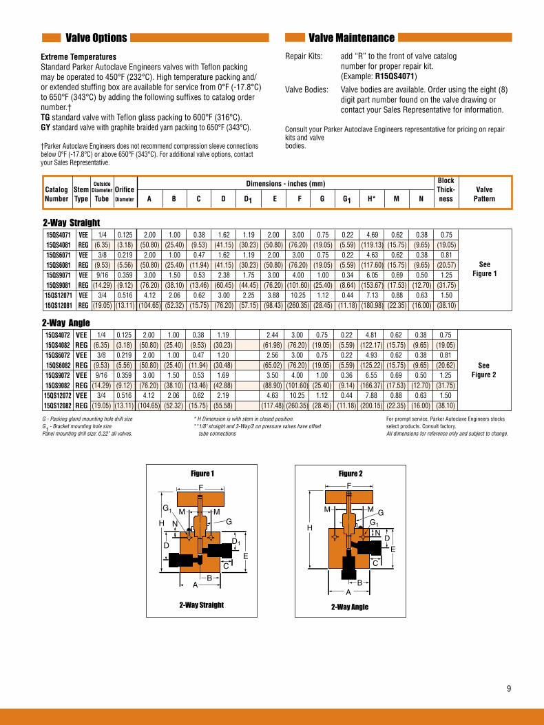
9
Valve MaintenanceValve OptionsExtremeTemperatures Standard Parker Autoclave Engineers valves with Teflon packing may be operated to 450°F (232°C). High temperature packing and/or extended stuffing box are available for service from 0°F (-17.8°C) to 650°F (343°C) by adding the following suffixes to catalog order number.†TG standard valve with Teflon glass packing to 600°F (316°C).GY standard valve with graphite braided yarn packing to 650°F (343°C).
†Parker Autoclave Engineers does not recommend compression sleeve connections below 0°F (-17.8°C) or above 650°F (343°C). For additional valve options, contact your Sales Representative.
Repair Kits: add “R” to the front of valve catalog number for proper repair kit. (Example:R15QS4071)
Valve Bodies: Valve bodies are available. Order using the eight (8) digit part number found on the valve drawing or contact your Sales Representative for information. Consult your Parker Autoclave Engineers representative for pricing on repair kits and valve bodies.
G - Packing gland mounting hole drill size * H Dimension is with stem in closed position. For prompt service, Parker Autoclave Engineers stocks G1 - Bracket mounting hole size **1/8" straight and 3-Way/2 on pressure valves have offset select products. Consult factory. Panel mounting drill size: 0.22” all valves. tube connections All dimensions for reference only and subject to change.
Block Catalog StemDiameterOrifice Thick- ValveNumber Type Tube Diameter A B C D D1 E F G G1 H* M N ness Pattern
Dimensions-inches(mm)
2-Way Straight 15QS4071 VEE 15QS4081 REG 15QS6071 VEE 15QS6081 REG 15QS9071 VEE 15QS9081 REG 15QS12071 VEE 15QS12081 REG
1/4 0.125 2.00 1.00 0.38 1.62 1.19 2.00 3.00 0.75 0.22 4.69 0.62 0.38 0.75 (6.35) (3.18) (50.80) (25.40) (9.53) (41.15) (30.23) (50.80) (76.20) (19.05) (5.59) (119.13) (15.75) (9.65) (19.05) 3/8 0.219 2.00 1.00 0.47 1.62 1.19 2.00 3.00 0.75 0.22 4.63 0.62 0.38 0.81 (9.53) (5.56) (50.80) (25.40) (11.94) (41.15) (30.23) (50.80) (76.20) (19.05) (5.59) (117.60) (15.75) (9.65) (20.57) 9/16 0.359 3.00 1.50 0.53 2.38 1.75 3.00 4.00 1.00 0.34 6.05 0.69 0.50 1.25 (14.29) (9.12) (76.20) (38.10) (13.46) (60.45) (44.45) (76.20) (101.60) (25.40) (8.64) (153.67) (17.53) (12.70) (31.75) 3/4 0.516 4.12 2.06 0.62 3.00 2.25 3.88 10.25 1.12 0.44 7.13 0.88 0.63 1.50 (19.05) (13.11) (104.65) (52.32) (15.75) (76.20) (57.15) (98.43) (260.35) (28.45) (11.18) (180.98) (22.35) (16.00) (38.10)
Outside
See Figure1
2-Way Straight
Figure 1
H N
F
G1
G
D1DE
M M
AB
C
2-Way Angle 15QS4072 VEE 15QS4082 REG 15QS6072 VEE 15QS6082 REG 15QS9072 VEE 15QS9082 REG 15QS12072 VEE 15QS12082 REG
1/4 0.125 2.00 1.00 0.38 1.19 2.44 3.00 0.75 0.22 4.81 0.62 0.38 0.75 (6.35) (3.18) (50.80) (25.40) (9.53) (30.23) (61.98) (76.20) (19.05) (5.59) (122.17) (15.75) (9.65) (19.05) 3/8 0.219 2.00 1.00 0.47 1.20 2.56 3.00 0.75 0.22 4.93 0.62 0.38 0.81 (9.53) (5.56) (50.80) (25.40) (11.94) (30.48) (65.02) (76.20) (19.05) (5.59) (125.22) (15.75) (9.65) (20.62) 9/16 0.359 3.00 1.50 0.53 1.69 3.50 4.00 1.00 0.36 6.55 0.69 0.50 1.25 (14.29) (9.12) (76.20) (38.10) (13.46) (42.88) (88.90) (101.60) (25.40) (9.14) (166.37) (17.53) (12.70) (31.75) 3/4 0.516 4.12 2.06 0.62 2.19 4.63 10.25 1.12 0.44 7.88 0.88 0.63 1.50 (19.05) (13.11) (104.65) (52.32) (15.75) (55.58) (117.48) (260.35) (28.45) (11.18) (200.15) (22.35) (16.00) (38.10)
See Figure2
2-Way Angle
Figure 2
H
F
G1
G
D
E
A
M
C
B
M
N

10
This page left blank
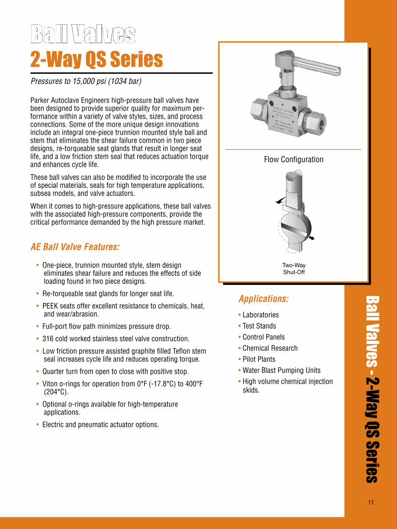
11
Ball Valves2-Way QS SeriesPressures to 15,000 psi (1034 bar)
Ball Valves - 2-Way QS Series
Flow Configuration
Two-WayShut-Off
Applications:
• Laboratories• Test Stands• Control Panels• Chemical Research• Pilot Plants• Water Blast Pumping Units• High volume chemical injection
skids.
Parker Autoclave Engineers high-pressure ball valves have been designed to provide superior quality for maximum per-formance within a variety of valve styles, sizes, and process connections. Some of the more unique design innovations include an integral one-piece trunnion mounted style ball and stem that eliminates the shear failure common in two piece designs, re-torqueable seat glands that result in longer seat life, and a low friction stem seal that reduces actuation torque and enhances cycle life.
These ball valves can also be modified to incorporate the use of special materials, seals for high temperature applications, subsea models, and valve actuators.
When it comes to high-pressure applications, these ball valves with the associated high-pressure components, provide the critical performance demanded by the high pressure market.
AE Ball Valve Features:
• One-piece, trunnion mounted style, stem design eliminates shear failure and reduces the effects of side loading found in two piece designs.
• Re-torqueable seat glands for longer seat life.
• PEEK seats offer excellent resistance to chemicals, heat, and wear/abrasion.
• Full-port flow path minimizes pressure drop.
• 316 cold worked stainless steel valve construction.
• Low friction pressure assisted graphite filled Teflon stem seal increases cycle life and reduces operating torque.
• Quarter turn from open to close with positive stop.
• Viton o-rings for operation from 0°F (-17.8°C) to 400°F (204°C).
• Optional o-rings available for high-temperature applications.
• Electric and pneumatic actuator options.
11

12
Ball Valves - 1/4” 2-Way QS SeriesPressures to 15,000 psi (1034 bar) .250” (6.35mm) Orifice
Ordering ProcedureFor complete information on available end connections see complete catalog.
4-1/4”(6.35 mm)
S -316SS Q4- QS 250
(See Chart on next page)
Q4End Connection
15Pressure(X1000psi)
SMaterial
4BallOrificeDiameter
2BValveSeries
2B: 2-way
MAWP@ MinimumOrifice Connection RoomTemperature inches(mm)
QS250 15,000 psi (1034 bar) .157 (3.99)
QS375 15,000 psi (1034 bar) .250 (6.35)
Valve Cv=1.51
HT- High Temperature
XXXOptions
(Ball Valve Actuators, see next page)
MAWP: Maximum Allowable Working PressureCv listed is for maximum orifice size of .250 inches only.
Consult factory for Cv of valves with reduced orifice sizes.
NOTE: Ball valves are not recommended for critical gas applications such as Hydrogen, Helium or other small molecular gases.
Typical catalog number: 2B4S15Q4
TEMPERATURE ˚F
100 200 300 400 5000
5,000
10,000
15,000
20,000
PR
ES
SU
RE
PS
IG
PRESSURE TEMPERATURE RATINGS
QS CONNECTION
(1379)
(1034)
(690)
(345)
TEMPERATURE ˚C
(-18) (38) (93) (150) (204) (260)
PR
ES
SU
RE
BA
R
STAINLESS STEEL HANDLE
STOPPING DEVICE
PACKING GLAND
LOCKING PIECE
SEAT GLAND
VITON O-RING
SEAT RETAINER
PEEK BEARING
LOCKNUT
SPRING ENERGIZED SEAL
THRUST WASHER
ONE PIECE BALLAND STEM
PEEK SEATS
13
End Connection Options
Catalog EndConnection MAWP@ Hex Number Number Connection RoomTemperature Inches(mm)
2B4S15Q4 Q4 QS250 15,000 psi (1034 bar) 1 (25.40)
2B4S15Q6 Q6 QS375 15,000 psi (1034 bar) 1 (25.40)
PneumaticActuator AO - Air-to-open/spring to close AC - Air-to-close/spring to open AOC - Air-to-open-and-close (double action)
ElectricActuator EO1 - 120 volt AC 50/60 Hz EO2 - 220 volt AC 50/60 Hz EO3 - 24 VDC
ActuatorOperatingTemperature: Pneumatic: -20˚F to 175˚F (-29˚C to 79˚C) Electric: -20˚F to 160˚F (-29˚C to 71˚C)
HighTemperatureOption: HT - for media temperature up to 500˚F (260˚C)
See ball valve actuator section for full description, additional infomation, and options.
RepairKits: add “R” to the front of valve catalog first 4 numbers for proper repair kit. (Example:R2B4S)
Consult your Parker Autoclave Engineers representative for pricing on repair kits. Refer to the Operation and Mainte-nance manual for proper maintenance procedures.
Valve Maintenance
MAWP: Maximum Allowable Working Pressure
Ball Valve Options
SeatGland
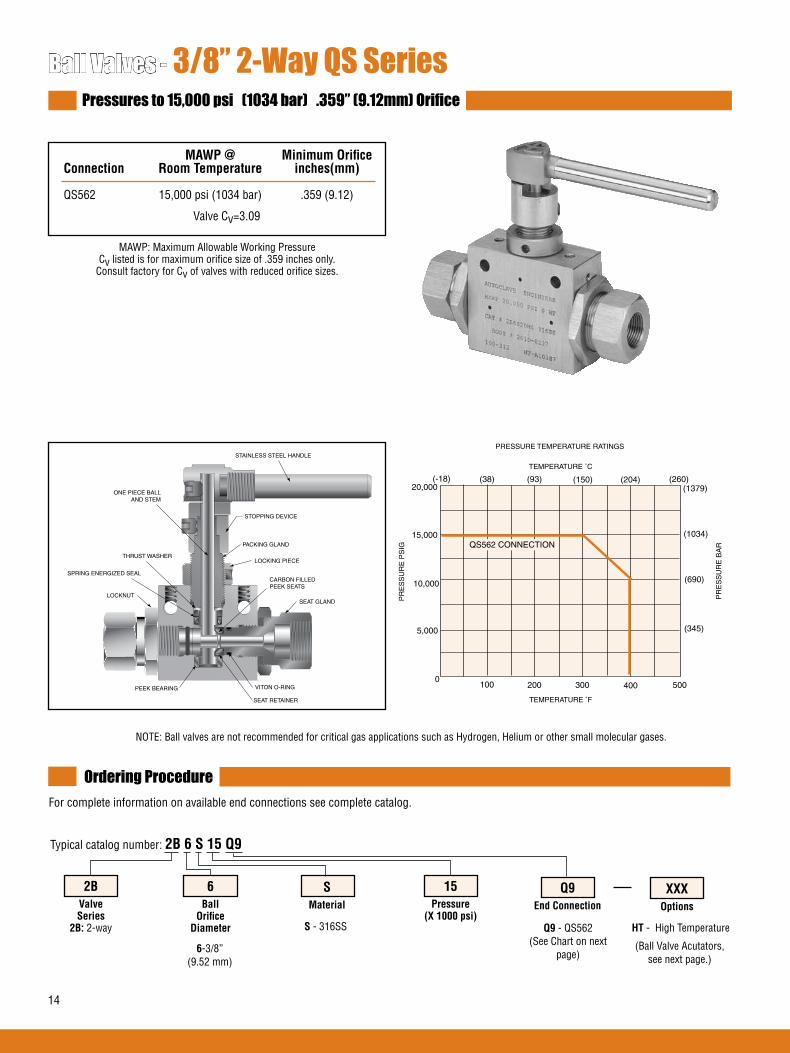
14
Ball Valves - 3/8” 2-Way QS SeriesPressures to 15,000 psi (1034 bar) .359” (9.12mm) Orifice
Ordering ProcedureFor complete information on available end connections see complete catalog.
6-3/8”(9.52 mm)
S - 316SS Q9- QS562 (See Chart on next
page)
Q9End Connection
15Pressure(X1000psi)
SMaterial
6BallOrificeDiameter
2BValveSeries
2B: 2-way
MAWP@ MinimumOrifice Connection RoomTemperature inches(mm)
QS562 15,000 psi (1034 bar) .359 (9.12)
Valve Cv=3.09
HT- High Temperature
XXXOptions
(Ball Valve Acutators,see next page.)
MAWP: Maximum Allowable Working PressureCv listed is for maximum orifice size of .359 inches only.
Consult factory for Cv of valves with reduced orifice sizes.
NOTE: Ball valves are not recommended for critical gas applications such as Hydrogen, Helium or other small molecular gases.
STAINLESS STEEL HANDLE
STOPPING DEVICE
PACKING GLAND
LOCKING PIECE
SEAT GLAND
VITON O-RING
SEAT RETAINER
PEEK BEARING
LOCKNUT
SPRING ENERGIZED SEAL
THRUST WASHER
ONE PIECE BALLAND STEM
CARBON FILLEDPEEK SEATS
Typical catalog number: 2B6S15Q9
TEMPERATURE ˚F
100 200 300 400 5000
5,000
10,000
15,000
20,000
PR
ES
SU
RE
PS
IG
PRESSURE TEMPERATURE RATINGS
QS562 CONNECTION
(1379)
(1034)
(690)
(345)
TEMPERATURE ˚C
(-18) (38) (93) (150) (204) (260)
PR
ES
SU
RE
BA
R
15
Ball Valve Options
PneumaticActuator AO - Air-to-open/spring to close AC - Air-to-close/spring to open AOC - Air-to-open-and-close (double action)
ElectricActuator EO1 - 120 volt AC 50/60 Hz EO2 - 220 volt AC 50/60 Hz EO3 - 24 VDC
ActuatorOperatingTemperature: Pneumatic: -20˚F to 175˚F (-29˚C to 79˚C) Electric: -20˚F to 160˚F (-29˚C to 71˚C)
HighTemperatureOption: HT - for media temperature up to 500˚F (260˚C)
See ball valve actuator section for full description, additional information, and options.
RepairKits: add “R” to the front of valve catalog first 4 numbers for proper repair kit. (Example:R2B6S)
Consult your Parker Autoclave Engineers representative for pricing on repair kits. Refer to the Operation and Maintenance manual for proper maintenance procedures.
Valve Maintenance
End Connection Options
Catalog EndConnection MAWP@ Hex Number Number Connection RoomTemperature Inches(mm)
2B6S15Q9 Q9 QS562 15,000 psi (1034 bar) 1.38 (35.05)
MAWP: Maximum Allowable Working Pressure
SeatGland

16
Ball Valves - 1/2” 2-Way QS SeriesPressures to 15,000 psi (1034 bar) .500” (12.7mm) Orifice
Ordering ProcedureFor complete information on available end connections see complete catalog.
8-1/2”(12.7 mm)
S -316SS MAQ12- Male QS750
(See Chart on next page)
MAQ12End Connection
15Pressure(X1000psi)
SMaterial
8BallOrificeDiameter
2BValveSeries
2B: 2-way
MAWP@ MinimumOrifice Connection RoomTemperature Inches(mm)
Male QS750 15,000 psi (1034 bar) .500 (12.70)
Valve Cv=10.20
HT- High Temperature
XXXOptions
(Ball Valve Acutators,see next page.)
MAWP: Maximum Allowable Working Pressure
NOTE: Ball valves are not recommended for critical gas applications such as Hydrogen, Helium or other small molecular gases.
Typical catalog number: 2B8S15MAQ12
TEMPERATURE ˚F
100 200 300 400 5000
5,000
10,000
15,000
PR
ES
SU
RE
PS
IG
PRESSURE TEMPERATURE RATINGS
QS750 CONNECTION(1034)
(690)
(345)
TEMPERATURE ˚C
(-18) (38) (93) (150) (204) (260)
PR
ES
SU
RE
BA
R
STAINLESS STEEL HANDLE
STOPPING DEVICE
PACKING GLAND
LOCKING PIECE
SEAT GLAND
VITON O-RING
SEAT RETAINER
PEEK BEARING
LOCKNUT
SPRING ENERGIZED SEAL
THRUST WASHER
ONE PIECE BALLAND STEM
CARBON FILLEDPEEK SEATS

17
Ball Valve Options
PneumaticActuator AO - Air-to-open/spring to close AC - Air-to-close/spring to open AOC - Air-to-open-and-close (double action)
ElectricActuator EO1 - 120 volt AC 50/60 Hz EO2 - 220 volt AC 50/60 Hz EO3 - 24 VDC
ActuatorOperatingTemperature: Pneumatic: -20˚F to 175˚F (-29˚C to 79˚C) Electric: -20˚F to 160˚F (-29˚C to 71˚C)
HighTemperatureOption: HT - for media temperature up to 500˚F (260˚C)
See ball valve Actuator section for full description, additional information, and options.
RepairKits: add “R” to the front of valve catalog first 4 numbers for proper repair kit. (Example: R2B8S)
Consult your Parker Autoclave Engineers representative for pricing on repair kits. Refer to the Operation and Mainte-nance manual for proper maintenance procedures.
Valve Maintenance
End Connection Options
MAWP: Maximum Allowable Working Pressure
SeatGland Catalog EndConnection MAWP@ Square Number Number Connection RoomTemperature Inches(mm)
2B8S15MAQ12 MAQ12 Male QS750 15,000 psi (1034 bar) 1.19 (30.2)
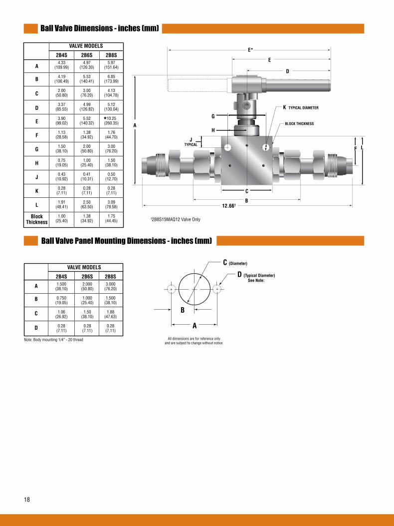
18
Ball Valve Dimensions - inches (mm)
Ball Valve Panel Mounting Dimensions - inches (mm)
VALVEMODELS
2B4S 2B6S 2B8S 1.500 2.000 3.000 (38.10) (50.80) (76.20)
0.750 1.000 1.500 (19.05) (25.40) (38.10)
1.06 1.50 1.88 (26.92) (38.10) (47.63)
0.28 0.28 0.28 (7.11) (7.11) (7.11)
Note: Body mounting 1/4” - 20 thread
A
B
C
D
E
F
G
H
J
K
L
BlockThickness
A
B
C
D
L
K TYPICAL DIAMETER
BLOCK THICKNESS
B
D
12.66†
C
F
A
JTYPICAL
H
G
E
E* VALVEMODELS
2B4S 2B6S 2B8S 4.33 4.97 5.97 (109.99) (126.30) (151.64)
4.19 5.53 6.85 (106.49) (140.41) (173.99)
2.00 3.00 4.13 (50.80) (76.20) (104.78)
3.37 4.99 5.12 (85.55) (126.82) (130.04)
3.90 5.52 10.25 (99.02) (140.32) (260.35)
1.13 1.38 1.76 (28.58) (34.92) (44.70)
1.50 2.00 3.00 (38.10) (50.80) (76.20)
0.75 1.00 1.50 (19.05) (25.40) (38.10)
0.43 0.41 0.50 (10.92) (10.31) (12.70)
0.28 0.28 0.28 (7.11) (7.11) (7.11)
1.91 2.50 3.09 (48.41) (63.50) (78.58)
1.00 1.38 1.75 (25.40) (34.92) (44.45)
*
†2B8S15MAQ12 Valve Only
C (Diameter)
D (Typical Diameter)
A
B
All dimensions are for reference only and are subject to change without notice.
See Note:

19
Ball Valves3-Way QS SeriesPressures to 15,000 psi (1034 bar)
Parker Autoclave Engineers high-pressure ball valves have been designed to provide superior quality for maximum per-formance within a variety of valve styles, sizes, and process connections. Some of the more unique design innovations include an integral one-piece trunnion mounted style ball and stem that eliminates the shear failure common in two piece designs, re-torqueable seat glands that result in longer seat life, and a low friction stem seal that reduces actuation torque and enhances cycle life.
These ball valves can also be modified to incorporate the use of special materials, seals for high temperature applications, subsea models, and valve actuators.
When it comes to high-pressure applications, these ball valves with the associated high-pressure components, provide the critical performance demanded by the high pressure market.
AE Ball Valve Features:
• One-piece, trunnion mounted style, stem design eliminates shear failure found in two piece designs and reduces effects of side loading.
• Re-torqueable seat glands for longer seat life.
• Carbon filled PEEK seats offer excellent resistance to chemicals, heat, and wear/abrasion.
• Full-port flow path minimizes pressure drop.
• 316 cold worked stainless steel valve construction.
• Low friction pressure assisted graphite filled Teflon stem seal increases cycle life and reduces operating torque.
• Available in 90° turn diverter and 180° turn switching models.
• Viton o-rings for operation from 0°F (-17.8°C) to 400°F (204°C).
• Optional o-rings available for high-temperature applications.
• Electric and pneumatic actuator options.
Ball Valves - 3-Way QS Series
Flow Configuration
Applications:
• Laboratories• Test Stands• Control Panels• Chemical Research• Pilot Plants• Water Blast Pumping Units• High volume chemical injection
skids.
3-WayDiverting
90 Turn
3-WaySwitching
180 Turn
3-WayCrossover90° Turn
3-WaySwitching180° Turn
19
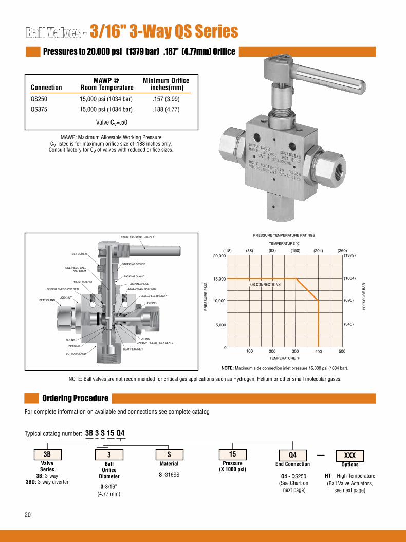
20
Ball Valves - 3/16" 3-Way QS SeriesPressures to 20,000 psi (1379 bar) .187” (4.77mm) Orifice
Ordering ProcedureFor complete information on available end connections see complete catalog
3-3/16”(4.77 mm)
S -316SS Q4- QS250 (See Chart on next page)
Q4End Connection
15Pressure(X1000psi)
SMaterial
3BallOrificeDiameter
3BValveSeries3B:3-way
3BD: 3-way diverter
MAWP@ MinimumOrifice Connection RoomTemperature inches(mm)
QS250 15,000 psi (1034 bar) .157 (3.99)
QS375 15,000 psi (1034 bar) .188 (4.77)
HT- High Temperature
XXXOptions
(Ball Valve Actuators, see next page)
MAWP: Maximum Allowable Working PressureCv listed is for maximum orifice size of .188 inches only.
Consult factory for Cv of valves with reduced orifice sizes.
NOTE: Ball valves are not recommended for critical gas applications such as Hydrogen, Helium or other small molecular gases.
Valve Cv=.50
STAINLESS STEEL HANDLE
STOPPING DEVICE
PACKING GLAND
LOCKING PIECE
O-RING
O-RING
SEAT RETAINER
BOTTOM GLAND
LOCKNUT
SPRING ENERGIZED SEAL
THRUST WASHER
SET SCREW
BELLEVILLE BACKUP
BEARING
O-RINGCARBON FILLED PEEK SEATS
SEAT GLAND
BELLEVILLE WASHERS
ONE PIECE BALLAND STEM
Typical catalog number: 3B3S15Q4
TEMPERATURE ˚F
100 200 300 400 5000
5,000
10,000
15,000
20,000
PR
ES
SU
RE
PS
IG
PRESSURE TEMPERATURE RATINGS
PR
ES
SU
RE
BA
R
(345)
(690)
(1034)
(1379)(-18) (38) (93) (150) (204) (260)
TEMPERATURE ˚C
QS CONNECTIONS
NOTE: Maximum side connection inlet pressure 15,000 psi (1034 bar).
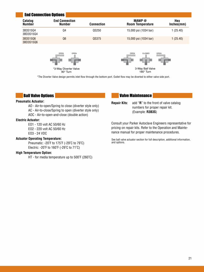
21
End Connection Options Catalog EndConnection MAWP@ Hex Number Number Connection RoomTemperature Inches(mm)
3B3S15Q4 Q4 QS250 15,000 psi (1034 bar) 1 (25.40) 3BD3S15Q4 3B3S15Q6 Q6 QS375 15,000 psi (1034 bar) 1 (25.40) 3BD3S15Q6
Ball Valve OptionsPneumaticActuator: AO - Air-to-open/Spring to close (diverter style only) AC - Air-to-close/Spring to open (diverter style only) AOC - Air-to-open-and-close (double action)ElectricActuator: EO1 - 120 volt AC 50/60 Hz EO2 - 220 volt AC 50/60 Hz EO3 - 24 VDCActuatorOperatingTemperature: Pneumatic: -20˚F to 175˚F (-29˚C to 79˚C) Electric: -20˚F to 160˚F (-29˚C to 71˚C)HighTemperatureOption: HT - for media temperature up to 500˚F (260˚C)
RepairKits: add “R” to the front of valve catalog numbers for proper repair kit. (Example:R3B3S)
Consult your Parker Autoclave Engineers representative for pricing on repair kits. Refer to the Operation and Mainte-nance manual for proper maintenance procedures.
Valve Maintenance
*The Diverter Valve design permits inlet flow through the bottom port. Outlet flow may be diverted to either valve side port.
OPEN OPEN
*3-Way Diverter Valve 90° Turn
OPEN CLOSED
3-Way Ball Valve180 Turn
OPEN
See ball valve actuator section for full description, additional information, and options.
*3-Way Diverter Valve90° Turn
3-Way Ball Valve180° Turn

22
Ball Valves - 3/8" 3-Way QS SeriesPressures to 15,000 psi (1034 bar) .328” (8.33mm) Orifice
Ordering ProcedureFor complete information on available end connections see complete catalog.
6-3/8”(9.52 mm)
S -316SS Q9- QS562
(See Chart on next page)
Q9End Connection
15Pressure(X1000psi)
SMaterial
6BallOrificeDiameter
3BValveSeries3B:3-way
3BD: 3-way diverterHT- High Temperature
XXXOptions
(Ball Valve Actuators, see next page)
MAWP: Maximum Allowable Working PressureCv listed is for maximum orifice size of .328 inches only.
Consult factory for Cv of valves with reduced orifice sizes.
NOTE: Ball valves are not recommended for critical gas applications such as Hydrogen, Helium or other small molecular gases.
STAINLESS STEEL HANDLE
STOPPING DEVICE
PACKING GLAND
LOCKING PIECE
O-RING
O-RING
SEAT RETAINER
BOTTOM GLAND
LOCKNUT
SPRING ENERGIZED SEAL
THRUST WASHER
SET SCREW
BELLEVILLE BACKUP
BEARING
O-RINGCARBON FILLED PEEK SEATS
SEAT GLAND
BELLEVILLE WASHERS
ONE PIECE BALLAND STEM
MAWP@ MinimumOrifice Connection RoomTemperature inches(mm)
QS562 15,000 psi (1034 bar) .328 (8.33)
Valve Cv=2.1
Typical catalog number: 3B6S15Q9
TEMPERATURE ˚F
100 200 300 400 5000
5,000
10,000
15,000
PR
ES
SU
RE
PS
IG
PRESSURE TEMPERATURE RATINGS
Side connection pressure not recommended.
(345)
(690)
(1034)(-18) (38) (93) (150) (204) (260)
TEMPERATURE ˚C
PR
ES
SU
RE
BA
R
QS CONNECTION
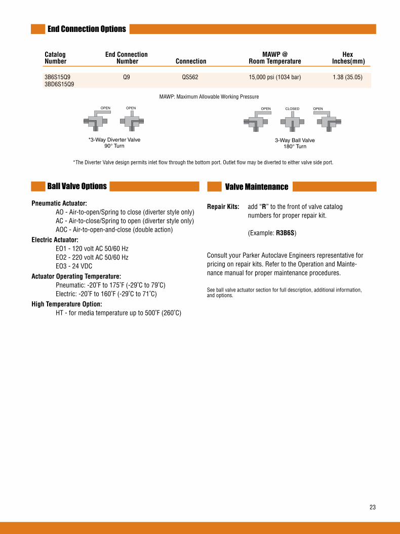
23
End Connection Options
Catalog EndConnection MAWP@ Hex Number Number Connection RoomTemperature Inches(mm)
3B6S15Q9 Q9 QS562 15,000 psi (1034 bar) 1.38 (35.05) 3BD6S15Q9
Ball Valve Options
PneumaticActuator: AO - Air-to-open/Spring to close (diverter style only) AC - Air-to-close/Spring to open (diverter style only) AOC - Air-to-open-and-close (double action)ElectricActuator: EO1 - 120 volt AC 50/60 Hz EO2 - 220 volt AC 50/60 Hz EO3 - 24 VDCActuatorOperatingTemperature: Pneumatic: -20˚F to 175˚F (-29˚C to 79˚C) Electric: -20˚F to 160˚F (-29˚C to 71˚C)HighTemperatureOption: HT - for media temperature up to 500˚F (260˚C)
RepairKits: add “R” to the front of valve catalog numbers for proper repair kit. (Example:R3B6S)
Consult your Parker Autoclave Engineers representative for pricing on repair kits. Refer to the Operation and Mainte-nance manual for proper maintenance procedures.
See ball valve actuator section for full description, additional information, and options.
Valve Maintenance
*The Diverter Valve design permits inlet flow through the bottom port. Outlet flow may be diverted to either valve side port.
OPEN CLOSED
3-Way Ball Valve180 Turn
OPENOPEN OPEN
*3-Way Diverter Valve 90° Turn
MAWP: Maximum Allowable Working Pressure
*3-Way Diverter Valve90° Turn
3-Way Ball Valve180° Turn

24
Ball Valves - 1/2" 3-Way QS SeriesPressures to 10,000 psi (690 bar) .500” (12.7mm) Orifice
MAWP@ MinimumOrifice Connection RoomTemperature inches(mm)
Male QS750 10,000 psi (690 bar) .500 (12.70)
Valve Cv=4.4
Ordering ProcedureFor complete information on available end connections see complete catalog.
8-1/2”(12.7 mm)
S -316SS
(For material options contact factory)
MAQ12-Male QS750
(See Chart on next page)
MAQ12End Connection
10Pressure(X1000psi)
SMaterial
8BallOrificeDiameter
3BValveSeries3B:3-way
3BD: 3-way diverterHT- High Temperature
XXXOptions
(Ball Valve Actuators, see next page)
MAWP: Maximum Allowable Working Pressure
NOTE: Ball valves are not recommended for critical gas applications such as Hydrogen, Helium or other small molecular gases.
Typical catalog number: 3B8S10MAQ12
TEMPERATURE ˚F
100 200 300 400 5000
5,000
10,000
15,000
PR
ES
SU
RE
PS
IG
PRESSURE TEMPERATURE RATINGS
QS CONNECTION
Maximum side connection inlet pressure 10,000 psi (690 bar)
(345)
(690)
(1034)(-18) (38) (93) (150) (204) (260)
TEMPERATURE ˚C
PR
ES
SU
RE
BA
R
STAINLESS STEEL HANDLE
STOPPING DEVICE
PACKING GLAND
LOCKING PIECE
BOTTOM BEARING
STEM SEAL
THRUST WASHER
SEAT RETAINER
BOTTOM GLAND
O-RING
SET SCREW
LOCKNUTSEAT GLAND
ONE PIECE BALLAND STEM
BELLEVILLE WASHERSBELLEVILLE BACKUP
CARBON FILLED PEEK SEATS
O-RINGO-RING
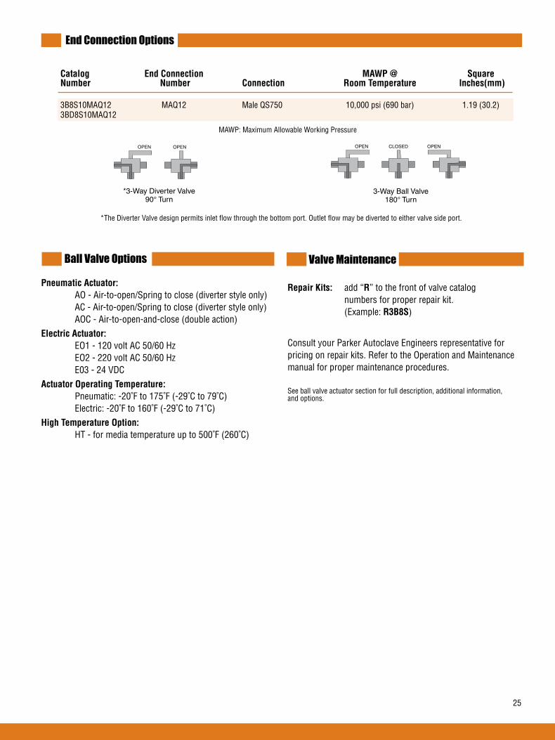
25
End Connection Options
Catalog EndConnection MAWP@ Square Number Number Connection RoomTemperature Inches(mm)
3B8S10MAQ12 MAQ12 Male QS750 10,000 psi (690 bar) 1.19 (30.2) 3BD8S10MAQ12
Ball Valve Options
PneumaticActuator: AO - Air-to-open/Spring to close (diverter style only) AC - Air-to-open/Spring to close (diverter style only) AOC - Air-to-open-and-close (double action)ElectricActuator: EO1 - 120 volt AC 50/60 Hz EO2 - 220 volt AC 50/60 Hz E03 - 24 VDCActuatorOperatingTemperature: Pneumatic: -20˚F to 175˚F (-29˚C to 79˚C) Electric: -20˚F to 160˚F (-29˚C to 71˚C)HighTemperatureOption: HT - for media temperature up to 500˚F (260˚C)
RepairKits: add “R” to the front of valve catalog numbers for proper repair kit. (Example:R3B8S)
Consult your Parker Autoclave Engineers representative for pricing on repair kits. Refer to the Operation and Maintenance manual for proper maintenance procedures.
See ball valve actuator section for full description, additional information, and options.
Valve Maintenance
*The Diverter Valve design permits inlet flow through the bottom port. Outlet flow may be diverted to either valve side port.
OPEN OPEN
*3-Way Diverter Valve 90° Turn
OPEN CLOSED
3-Way Ball Valve180 Turn
OPEN
MAWP: Maximum Allowable Working Pressure
*3-Way Diverter Valve90° Turn
3-Way Ball Valve180° Turn
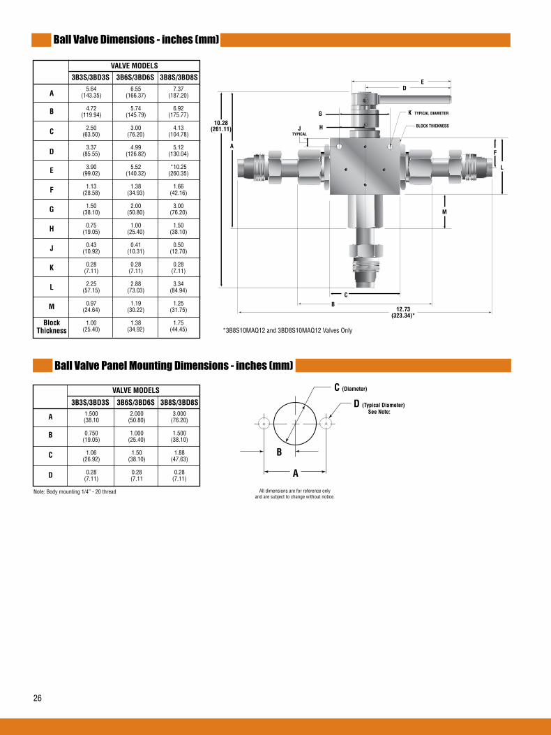
26
Ball Valve Dimensions - inches (mm)
Ball Valve Panel Mounting Dimensions - inches (mm)
Note: Body mounting 1/4” - 20 thread
VALVEMODELS
3B3S/3BD3S 3B6S/3BD6S 3B8S/3BD8S
A
B
C
D
A
B
C
D
E
F
G
H
J
K
L
M
BlockThickness
5.64 6.55 7.37 (143.35) (166.37) (187.20)
4.72 5.74 6.92 (119.94) (145.79) (175.77)
2.50 3.00 4.13 (63.50) (76.20) (104.78)
3.37 4.99 5.12 (85.55) (126.82) (130.04)
3.90 5.52 *10.25 (99.02) (140.32) (260.35)
1.13 1.38 1.66 (28.58) (34.93) (42.16)
1.50 2.00 3.00 (38.10) (50.80) (76.20)
0.75 1.00 1.50 (19.05) (25.40) (38.10)
0.43 0.41 0.50 (10.92) (10.31) (12.70)
0.28 0.28 0.28 (7.11) (7.11) (7.11) 2.25 2.88 3.34 (57.15) (73.03) (84.94)
0.97 1.19 1.25 (24.64) (30.22) (31.75)
1.00 1.38 1.75 (25.40) (34.92) (44.45)
1.500 2.000 3.000 (38.10 (50.80) (76.20)
0.750 1.000 1.500 (19.05) (25.40) (38.10)
1.06 1.50 1.88 (26.92) (38.10) (47.63)
0.28 0.28 0.28 (7.11) (7.11 (7.11)
VALVEMODELS
3B3S/3BD3S 3B6S/3BD6S 3B8S/3BD8S
*3B8S10MAQ12 and 3BD8S10MAQ12 Valves Only
C (Diameter)
D (Typical Diameter)
A
B
All dimensions are for reference only and are subject to change without notice.
See Note:
B
C
A
JTYPICAL
G
ED
L
K TYPICAL DIAMETER
BLOCK THICKNESSH
M
12.73 (323.34)*
10.28 (261.11)
F

2727
Ball ValvesActuatorsPneumatic Actuators Electric Actuators
Parker Autoclave Engineers ball valves can be supplied with either pneumatic or electric operators for automated or re-mote operation. Pneumatic and electric operators can be supplied with a vari-ety of features and options. Operators are sized for each valve series to provide reliable and trouble free operation. Listed below are the operator features and available options.
AE Ball Valve Actuator Features/Options:
PneumaticOperators
• Used for remote and automatic operation
• Air-to-open/spring-to-close
• Air-to-close/spring-to-open
• Air-to-open and close (double acting)
• Limit switches or limit switches with visual indicators available
• High temperature option available.
• Stainless steel housing for corrosive applications available.
• Optional solenoid valve available
• Standard anodized aluminum housing
• Optional epoxy coated housing available
ElectricOperators
• Interface with control systems for automated operation and monitoring
• 120 & 220 VAC, 50/60 Hz standard
• 24VDC
• Explosion proof available
• CE mark available
Ball Valves - Actuators
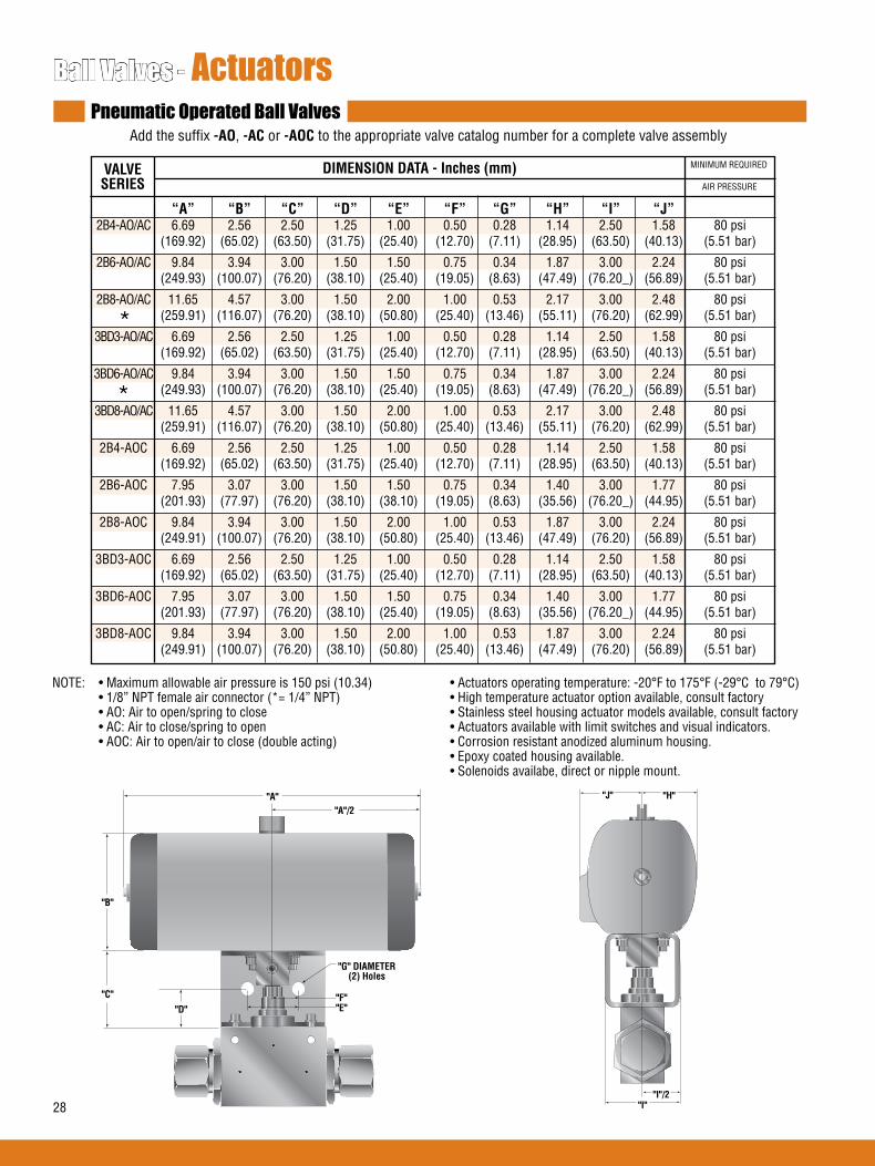
28
Ball Valves - ActuatorsPneumatic Operated Ball Valves
Add the suffix -AO, -ACor-AOC to the appropriate valve catalog number for a complete valve assembly
“A” “B” “C” “D” “E” “F” “G” “H” “I” “J” 2B4-AO/AC 6.69 2.56 2.50 1.25 1.00 0.50 0.28 1.14 2.50 1.58 80 psi (169.92) (65.02) (63.50) (31.75) (25.40) (12.70) (7.11) (28.95) (63.50) (40.13) (5.51 bar)
2B6-AO/AC 9.84 3.94 3.00 1.50 1.50 0.75 0.34 1.87 3.00 2.24 80 psi (249.93) (100.07) (76.20) (38.10) (25.40) (19.05) (8.63) (47.49) (76.20_) (56.89) (5.51 bar)
2B8-AO/AC 11.65 4.57 3.00 1.50 2.00 1.00 0.53 2.17 3.00 2.48 80 psi (259.91) (116.07) (76.20) (38.10) (50.80) (25.40) (13.46) (55.11) (76.20) (62.99) (5.51 bar)
3BD3-AO/AC 6.69 2.56 2.50 1.25 1.00 0.50 0.28 1.14 2.50 1.58 80 psi (169.92) (65.02) (63.50) (31.75) (25.40) (12.70) (7.11) (28.95) (63.50) (40.13) (5.51 bar)
3BD6-AO/AC 9.84 3.94 3.00 1.50 1.50 0.75 0.34 1.87 3.00 2.24 80 psi (249.93) (100.07) (76.20) (38.10) (25.40) (19.05) (8.63) (47.49) (76.20_) (56.89) (5.51 bar)
3BD8-AO/AC 11.65 4.57 3.00 1.50 2.00 1.00 0.53 2.17 3.00 2.48 80 psi (259.91) (116.07) (76.20) (38.10) (50.80) (25.40) (13.46) (55.11) (76.20) (62.99) (5.51 bar)
2B4-AOC 6.69 2.56 2.50 1.25 1.00 0.50 0.28 1.14 2.50 1.58 80 psi (169.92) (65.02) (63.50) (31.75) (25.40) (12.70) (7.11) (28.95) (63.50) (40.13) (5.51 bar)
2B6-AOC 7.95 3.07 3.00 1.50 1.50 0.75 0.34 1.40 3.00 1.77 80 psi (201.93) (77.97) (76.20) (38.10) (38.10) (19.05) (8.63) (35.56) (76.20_) (44.95) (5.51 bar)
2B8-AOC 9.84 3.94 3.00 1.50 2.00 1.00 0.53 1.87 3.00 2.24 80 psi (249.91) (100.07) (76.20) (38.10) (50.80) (25.40) (13.46) (47.49) (76.20) (56.89) (5.51 bar)
3BD3-AOC 6.69 2.56 2.50 1.25 1.00 0.50 0.28 1.14 2.50 1.58 80 psi (169.92) (65.02) (63.50) (31.75) (25.40) (12.70) (7.11) (28.95) (63.50) (40.13) (5.51 bar)
3BD6-AOC 7.95 3.07 3.00 1.50 1.50 0.75 0.34 1.40 3.00 1.77 80 psi (201.93) (77.97) (76.20) (38.10) (25.40) (19.05) (8.63) (35.56) (76.20_) (44.95) (5.51 bar)
3BD8-AOC 9.84 3.94 3.00 1.50 2.00 1.00 0.53 1.87 3.00 2.24 80 psi (249.91) (100.07) (76.20) (38.10) (50.80) (25.40) (13.46) (47.49) (76.20) (56.89) (5.51 bar)
VALVE SERIES
DIMENSIONDATA-Inches(mm) MINIMUM REQUIRED
AIR PRESSURE
NOTE: • Maximum allowable air pressure is 150 psi (10.34) • Actuators operating temperature: -20°F to 175°F (-29°C to 79°C) • 1/8” NPT female air connector (*= 1/4” NPT) • High temperature actuator option available, consult factory • AO: Air to open/spring to close • Stainless steel housing actuator models available, consult factory • AC: Air to close/spring to open • Actuators available with limit switches and visual indicators. • AOC: Air to open/air to close (double acting) • Corrosion resistant anodized aluminum housing. • Epoxy coated housing available. • Solenoids availabe, direct or nipple mount.
"C"
"D"
"G" DIAMETER(2) Holes
"F""E"
"B"
"A"/2"A"
"I""I"/2
"J" "H"
*
*
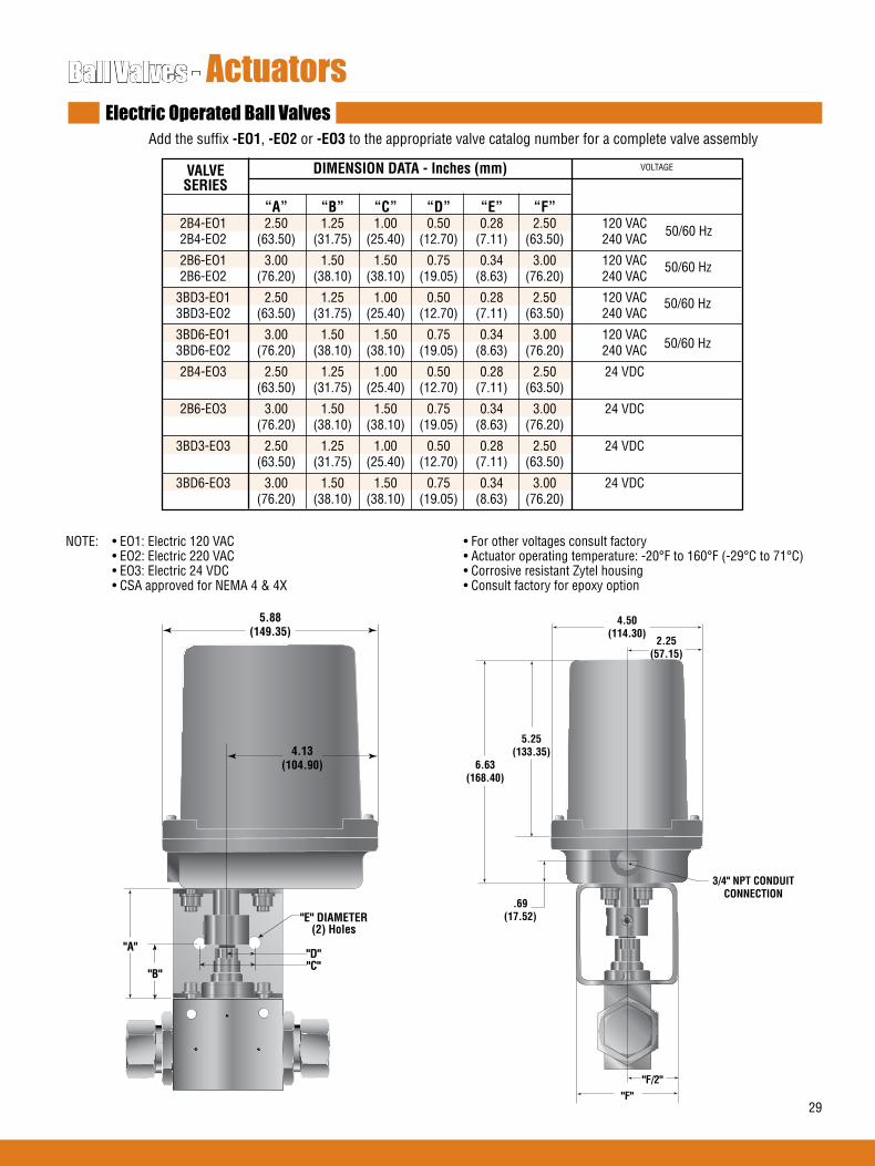
29
Ball Valves - ActuatorsElectric Operated Ball Valves
Add the suffix -EO1, -EO2 or -EO3 to the appropriate valve catalog number for a complete valve assembly
NOTE: • EO1: Electric 120 VAC • For other voltages consult factory • EO2: Electric 220 VAC • Actuator operating temperature: -20°F to 160°F (-29°C to 71°C) • EO3: Electric 24 VDC • Corrosive resistant Zytel housing • CSA approved for NEMA 4 & 4X • Consult factory for epoxy option
"B"
"E" DIAMETER(2) Holes
"D""C"
"A"
5.88(149.35)
4.13(104.90)
"F""F/2"
4.50(114.30)
3/4" NPT CONDUITCONNECTION
2.25(57.15)
5.25(133.35)
6.63(168.40)
.69(17.52)
VALVE SERIES
DIMENSIONDATA-Inches(mm) VOLTAGE
“A” “B” “C” “D” “E” “F” 2B4-EO1 2.50 1.25 1.00 0.50 0.28 2.50 120 VAC 2B4-EO2 (63.50) (31.75) (25.40) (12.70) (7.11) (63.50) 240 VAC
2B6-EO1 3.00 1.50 1.50 0.75 0.34 3.00 120 VAC 2B6-EO2 (76.20) (38.10) (38.10) (19.05) (8.63) (76.20) 240 VAC
3BD3-EO1 2.50 1.25 1.00 0.50 0.28 2.50 120 VAC 3BD3-EO2 (63.50) (31.75) (25.40) (12.70) (7.11) (63.50) 240 VAC
3BD6-EO1 3.00 1.50 1.50 0.75 0.34 3.00 120 VAC 3BD6-EO2 (76.20) (38.10) (38.10) (19.05) (8.63) (76.20) 240 VAC
2B4-EO3 2.50 1.25 1.00 0.50 0.28 2.50 24 VDC (63.50) (31.75) (25.40) (12.70) (7.11) (63.50)
2B6-EO3 3.00 1.50 1.50 0.75 0.34 3.00 24 VDC (76.20) (38.10) (38.10) (19.05) (8.63) (76.20)
3BD3-EO3 2.50 1.25 1.00 0.50 0.28 2.50 24 VDC (63.50) (31.75) (25.40) (12.70) (7.11) (63.50)
3BD6-EO3 3.00 1.50 1.50 0.75 0.34 3.00 24 VDC (76.20) (38.10) (38.10) (19.05) (8.63) (76.20)
50/60 Hz
50/60 Hz
50/60 Hz
50/60 Hz

30
Ball Valves - ActuatorsElectric Operated Ball Valves
Add the suffix -EO1, -EO2 or -EO3 to the appropriate valve catalog number for a complete valve assembly
2B8-EO1 120 VAC
3BD8-EO1 120 VAC
2B8-EO2 220 VAC
3BD8-EO2 220 VAC
VALVE SERIES
VOLTAGE
50/60 HZ
NOTE: • EO1: Electric 120 VAC • CE marked. • EO2: Electric 220 VAC • UL listed & CSA approved for NEMA 4, 4x, 7 & 9 • EO3: Electric 24 VDC • Explosion proof • For other voltages consult factory • Actuator operating temperature: -20°F to 160°F (-29°C to 71°C) • Powder coated aluminum housing
9.21(233.93)
3/4" NPT CONDUITCONNECTION
2.00 (50.80)1.00 (25.40)
0.53 (13.46)(2) HOLES
4.04(102.61)
11.04(280.29)
8.87(225.29)
1.50(38.10)
3.00(76.20)
3/4" NPT CONDUITCONNECTION
7.96(202.18)
3.98(101.09)
3.69(93.72)
1.63(41.40)
2.35(59.69)
1.50(38.10)3.00
(76.20)
VALVE SERIES
2B8-EO3 24 VDC
3BD8-EO3 24 VDC
2B8-EO3 24 VDC
3BD8-EO3 24 VDC
VOLTAGE
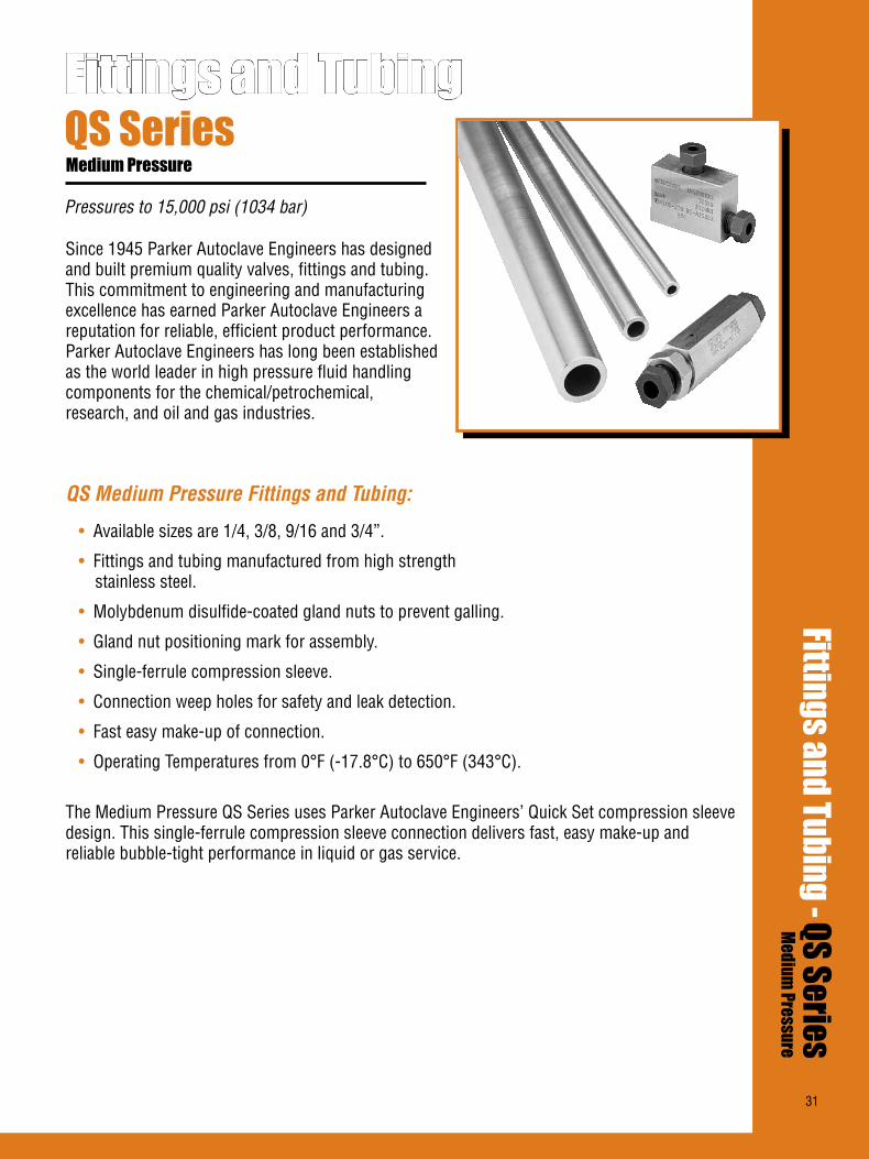
31
Since 1945 Parker Autoclave Engineers has designed and built premium quality valves, fittings and tubing. This commitment to engineering and manufacturing excellence has earned Parker Autoclave Engineers a reputation for reliable, efficient product performance. Parker Autoclave Engineers has long been established as the world leader in high pressure fluid handling components for the chemical/petrochemical, research, and oil and gas industries.
QS Medium Pressure Fittings and Tubing:
• Available sizes are 1/4, 3/8, 9/16 and 3/4”.
• Fittings and tubing manufactured from high strength stainless steel.
• Molybdenum disulfide-coated gland nuts to prevent galling.
• Gland nut positioning mark for assembly.
• Single-ferrule compression sleeve.
• Connection weep holes for safety and leak detection.
• Fast easy make-up of connection.
• Operating Temperatures from 0°F (-17.8°C) to 650°F (343°C).
The Medium Pressure QS Series uses Parker Autoclave Engineers’ Quick Set compression sleeve design. This single-ferrule compression sleeve connection delivers fast, easy make-up and reliable bubble-tight performance in liquid or gas service.
Pressures to 15,000 psi (1034 bar)
Fittings and TubingFittings and Tubing - QS Series
Medium Pressure
QS SeriesMedium Pressure
31

32
Elbow QSL4400 QS250 1/4 15,000 0.16 1.38 2.00 0.52 0.63 1.00 1.00 0.75 (6.35) (1034,20) (3.99) (34.93) (50.80) (13.23) (15.88) (25.40) (25.40) (19.05) QSL6600 QS375 3/8 15,000 0.25 1.50 2.00 0.55 0.75 1.00 1.00 0.81 (9.53) (1034,20) (6.35) (38.10) (50.80) (14.00) (19.05) (25.40) (25.40) (20.62) QSL9900 QS562 9/16 15,000 0.36 2.19 3.00 0.82 1.19 1.50 1.50 1.25 (14.29) (1034,20) (9.12) (55.58) (76.20) (20.83) (30.18) (38.10) (38.10) (31.75) QSL12 QS750 3/4 15,000 0.52 2.94 4.13 1.04 1.50 2.06 2.06 1.50 (19.05) (1034,20) (13.11) (74.63) (104.78) (26.37) (38.10) (52.40) (52.40) (38.10)
Dimensions-inches(mm)
See Figure1
Connection ComponentsAll Parker Autoclave Engineers valves and fittings are supplied complete with appropriate glands and sleeves. To order these com-ponents separately, use order numbers listed. When using plug, sleeve is not required.
To ensure proper fit use Parker Autoclave Engineers tubing. For mounting hole option add suffix PM to catalog number. Consult factory for mounting hole dimensions.
Gland QSG ( )
Add tube size ( ) Example: 1/4” - 40 1/4” Gland - QSG 40 3/8” - 60 9/16” - 90 3/4” - 120
Catalog Number
Connection Type
Outside Diameter
Tube
Pressure Rating
psi (bar)*
Minimum Opening
Block Thickness
Fitting Pattern A B C D E F G
Typical Thickness
Elbow
Figure 1
D HEXF
C
A
B
E
Plug QSP ( )
Sleeve QSS ( )
*Maximum pressure rating is based on the lowest rating of any component. Actual working pressure may be determined by tubing pressure rating, if lower.
All dimensions for reference only and subject to change.For prompt service, Parker Autoclave Engineers stocks select products. Consult your local representative.
For mounting hole option add suffix PM to catalog number. Consult factory for mounting hole dimensions.
Fittings and Tubing - QS SeriesPressures to 15,000 psi (1034 bar)
Parker Autoclave Engineers Medium Pressure QS Fittings are designed for use with QS Series valves and medium pressure tubing. These fittings feature improved compression connections with larger orifices for excellent flow capabilities. Autoclave fittings and components are manufactured of high strength stainless steel.

33
Dimensions-inches(mm)Catalog Number
Connection Type
Outside Diameter
Tube
Pressure Rating
psi (bar)*
Minimum Opening
Block Thickness
Fitting Pattern A B C D E F G
Typical Thickness
Tee
See Figure2
Cross
See Figure3
Cross
Figure 3
DHEX
F
C
A
B
E
Tee
Figure 2D HEX
F
C
A
B
E
*Maximum pressure rating is based on the lowest rating of any component. Actual working pressure may be determined by tubing pressure rating, if lower.
For mounting hole option add suffix PM to catalog number. Consult factory for mounting hole dimensions.
QST4440 QS250 1/4 15,000 0.16 1.38 2.00 0.52 0.63 1.00 1.00 0.75 (6.35) (1034,20) (3.99) (34.93) (50.80) (13.23) (15.88) (25.40) (25.40) (19.05) QST6660 QS375 3/8 15,000 0.25 1.50 2.00 0.55 0.75 1.00 1.00 0.81 (9.53) (1034,20) (6.35) (38.10) (50.80) (14.00) (19.05) (25.40) (25.40) (20.62) QST9990 QS562 9/16 15,000 0.36 2.19 3.00 0.82 1.19 1.50 1.50 1.25 (14.29) (1034,20) (9.12) (55.58) (76.20) (20.83) (30.18) (38.10) (38.10) (31.75) QST12 QS750 3/4 15,000 0.52 2.94 4.13 1.04 1.50 2.06 2.06 1.50 (19.05) (1034,20) (13.11) (74.63) (104.78) (26.37) (38.10) (52.40) (52.40) (38.10)
Dimensions-inches(mm)Catalog Number
Connection Type
Outside Diameter
Tube
Pressure Rating
psi (bar)*
Minimum Opening
Block Thickness
Fitting Pattern A B C D E F G
Typical Thickness
Straight Coupling 15F44QQ QS250 1/4 15,000 0.16 0.75 1.63 0.52 0.63 Straight (6.35) (1034,20) (3.99) (19.05) (41.28) (13.23) (15.88) 15F66QQ QS375 3/8 15,000 0.25 0.81 1.75 0.55 0.75 Straight (9.53) (1034,20) (6.35) (20.65) (44.45) (14.00) (19.05) 15F99QQ QS562 9/16 15,000 0.36 1.38 2.75 0.82 1.19 Straight (14.29) (1034,20) (9.12) (34.93) (69.85) (20.83) (30.18) 15F12Q QS750 3/4 15,000 0.52 1.50 3.75 1.04 1.50 Straight (19.05) (1034,20) (13.11) (38.10) (95.25) (26.37) (38.10)
See Figure4
Bulkhead Coupling 15BF44QQ QS250 1/4 15,000 0.16 0.88 2.00 0.52 0.63 0.63 1.00 0.38 (6.35) (1034,20) (3.99) (22.23) (50.80) (13.23) (15.88) (15.88) (25.40) (9.53) 15BF66QQ QS375 3/8 15,000 0.25 1.06 2.38 0.55 0.75 0.79 1.38 0.38 (9.53) (1034,20) (6.35) (27.00) (60.33) (14.00) (19.05) (19.94) (34.93) (9.53) 15BF99QQ QS562 9/16 15,000 0.36 1.63 2.63 0.82 1.19 0.91 1.88 0.38 (14.29) (1034,20) (9.12) (41.40) (66.68) (20.83) (30.18) (22.99) (47.75) (9.53) 15BF12Q QS750 3/4 15,000 0.52 1.88 3.50 1.04 1.50 1.50 2.13 0.38 (19.05) (1034,20) (13.11) (47.63) (88.90) (26.37) (38.10) (38.10) (53.98) (9.53)
See Figure5
Straight Coupling
Figure 4
Bulkhead Coupling
Figure 5
DHEX
CB
A HEX
Union Couplings are designed with a removable seat insert allowing disassembly and tubing removal without the necessity of loosening other items in a line.
All dimensions for reference only and subject to change.For prompt service, Autoclave stocks select products. Consult your local representative.
QSX4444 QS250 1/4 15,000 0.16 2.00 2.00 0.52 0.63 1.00 1.00 0.75 (6.35) (1034,20) (3.99) (50.80) (50.80) (13.23) (15.88) (25.40) (25.40) (19.05) QSX6666 QS375 3/8 15,000 0.25 2.00 2.00 0.55 0.75 1.00 1.00 0.81 (9.53) (1034,20) (6.35) (50.80) (50.80) (14.00) (19.05) (25.40) (25.40) (20.62) QSX9999 QS562 9/16 15,000 0.36 3.00 3.00 0.82 1.19 1.50 1.50 1.25 (14.29) (1034,20) (9.12) (76.20) (76.20) (20.83) (30.18) (38.10) (38.10) (31.75) QSX12 QS750 3/4 15,000 0.52 4.13 4.13 1.04 1.50 2.06 2.06 1.50 (19.05) (1034,20) (13.11) (104.78) (104.78) (26.37) (38.10) (52.40) (52.40) (38.10)
G MAX
CB
F
E
AD
HEX

34
Pressures to 15,000 psi (1034 bar)
Parker Autoclave Engineers offers a complete selection of austenetic, cold drawn stainless steel tubing designed to match the performance standards of Parker Autoclave Engineers valves and fittings. Parker Autoclave Engi-neers medium pressure tubing is manufactured specifically for high pressure applications requiring both strength and corrosion resistance. The tubing is furnished in random lengths between 20 feet (6 meters) and 27 feet (8.2 meters). The average is 24 feet (7.3 meters). Medium Pressure Tubing is available in four sizes and a variety of materials.
InspectionandTestingParker Autoclave Engineer’s medium pressure tubing is inspected to assure freedom from seams, laps, fissures or other flaws, as well as carburization or intergranular carbide precipitation. The outside and inside diameters of the tubing are subject to special inspection and are controlled within close tolerences to assure proper fit. Sample pieces of tube for each lot are tested to confirm mechanical properties. Hydrostatic testing is also performed on a statistical basis and is conducted at the working pressure of the tube. Parker Autoclave Engineers will perform 100% hydrostatic testing at additional cost if desired.
Medium Pressure Tubing
*Maximum pressure rating is based on the lowest rating of any component. Actual working pressure may be determined by tubing pressure rating, if lower.All dimensions for reference only and subject to change. For prompt service, Parker Autoclave Engineers stocks select products. Consult your local representative.**Larger inside diameters are available as special order.
TubingToleranceNominal Tubing Size Tolerance/Outside Diameterinches (mm) inches (mm)1/4 (6.35) .248/.243 (6.30/6.17)3/8 (9.53) .370/.365 (9.40/9.27)9/16 (14.27) .557/.552 (14.15/14.02)3/4 (19.05) .745/.740 (18.92/18.80)
MS15-092** 316SS 20,000 20,000 19,250 18,050 QS250 1/4 0.109 0.070 0.009 (1378.93) (1378.93) (1327.22) (1244.48) MS15-192** 304SS (6.35) (2.77) (1.78) (5.81) 20,000 18,950 17,200 17,000 (1378.93) (1306.54) (1185.88) (1172.09) MS15-093** 316SS 20,000 20,000 19,250 18,050 QS375 3/8 0.203 0.086 0.032 (1378.93) (1378.93) (1327.22) (1244.48) MS15-193** 304SS (9.53) (5.16) (2.18) (20.65) 20,000 20,000 19,250 18,050 (1378.93) (1378.93) (1327.22) (1244.48) MS15-097 316SS
Catalog Tube Fits Tube Size Inches (mm) Flow Working Pressure psi (bar)* Number Material Connection Outside Inside Wall Area -325 to 100°F 200°F 400°F 600°F Type Diameter Diameter Thickness in.2 (mm2) -198 to - 37.8°C 93°C 204°C 316°C
QS562 9/16 0.359 0.101 0.101 (14.29) (9.12) (2.57) (65.16)
MS15-098 316SS
15,000 15,000 14,400 13,650(1034.19) (1034.19) (992.82) (941.12)
QS750 3/4 0.516 0.117 0.209 15,000 15,000 14,400 13,650 (19.05) (13.11) (2.97) (134.84) (1034.19) (1034.19) (992.82) (941.12)

35
Pressures to 15,000 psi (1034 bar)
For rapid system make-up, Parker Autoclave Engineers supplies pre-assem-bled nipples in various sizes and lengths for Parker Autoclave Engineers QSS valves and fittings.
SpecialLengthsIn addition to the standard lengths listed in the table below, nipples areavailable in any custom length. Consult factory.
MaterialsCatalog numbers in table refer to Type 316 Stainless Steel.
Nipples - QS Series
Catalog NumbersNipple Length Inches (mm) Fits
ConnectionType
Tube SizeInches (mm)
Working Pressureat 100°psi (bar)
4.00” 6.00” 8.00” 10.00” 12.00” (101.60) (152.40) (203.20) (254.60) (304.80)
QNA4404-316 QNA4406-316 QNA4408-316 QNA44010-316 QNA44012-316 QS250 1/4” 0.109 15,000
(6.35) (2.77) (1034.16)
QNA6604-316 QNA6606-316 QNA6608-316 QNA66010-316 QNA66012-316 QS375 3/8” 0.203 15,000
(9.53) (5.16) (1034.16)
QNA9906-316 QNA9908-316 QNA99010-316 QNA99012-316 QS562 9/16” 0.359 15,000
(14.29) (9.12) (1034.16)
QNA1208-316 QNA12010-316 QNA12012-316 QS750 3/4” 0.516 15,000
(19.05) (13.11) (1034.16)
Close Tube Port Connectors
ModelSize
Inches (mm)Fits Connection
TypeDimension “L”Inches (mm)
QTS4403.25 1/4” (6.35) QS250 3.25 (82.55)
QTS6603.50 3/8” (9.53) QS375 3.50 (88.90)
QTS9905.25 9/16” (14.29) QS562 5.25 (133.35)
QTS1206.375 3/4” (19.05) QS750 6.38 (162.10)
Elbow Tube
Model SizeInches (mm)
Fits ConnectionType
Dimension “H”Inches (mm)
QTE44-90 1/4” (6.35) QS250 3.25 (82.55) 0.563 (14.30) 0.438 (11.13)
QTE66-90 3/8” (9.53) QS375 3.50 (88.90) 0.938 (23.83) 0.75 (19.05)
QTE99-90 9/16” (14.29) QS562 7.50 (19.05) 2.906 (73.82) 2.625 (66.68)
QTE12-90 3/4” (19.05) QS750 10.00 (254.00) 3.875 (98.43) 3.5 (88.9)
Mean Radius “R”Inches (mm)
Inside Radius RiInches (mm)
OD ID
L
H Typ.
R
Ri

36
Check Valves - QS SeriesPressures to 15,000 psi (1034 bar)
Provide unidirectional flow and tight shut-off for liquids and gases with high reliability. When differential drops below crack-ing pressure*, valve shuts off. (Notforuseasreliefvalve.)
Materials: 316 Stainless Steel: Body, cover, poppet, cover gland. 300 Stainless Steel: Spring.Standard O-ring: Viton, for operation to 500° F (260°C). Buna-N or Teflon available for 250°F (121°C) or 400°F (204°C) respectively; specify when ordering.
*Cracking Pressure: 20 psi (1.38 bar) ±30%. Springs for higher cracking pressures (up to 100 psi (6.89bar)) available on special order for O-ring style check valves only.
Prevent reverse flow where leak-tight shut-off is not mandatory. When differential drops below cracking pressure, valve closes. With all-metal components, valve can be used up to 650°F (343°C). See Technical Information section for con-nection temperature limitations. (Notforuseasareliefvalve.)
Ballandpoppetareanintegraldesign to assure positive, in-line seating without “chatter”. Poppet is designed essentially for axial flow with minimum pressure drop.
Materials: 316 Stainless Steel: Body, cover, cover gland, ball poppet. 300 Series Stainless Steel: Spring
O-Ring Check Valves
FLOW
Ball Check Valves
CAUTION: While testing has shown O-Rings to provide satisfactory service life, both cyclic and shelf life may vary widely with differing service conditions, properties of reactants, pressure and temperature cycling and age of the O-ring. FREQUENT INSPECTIONS SHOULD BE MADE to detect any deterioration, and O-rings replaced as required.
CAUTION: See Tubing section for proper selection of tubing.
O-Ring Check Valves
Dimensions-inches(mm)
See Figure1
Catalog Number
Fits Connection
Type
Orifice inches (mm)
Pressure Rating
psi (bar)*
Rated Cv A B C D Hex
Typical
Ball Check Valves
See Figure1
Figure 1Note: All check valves are furnished complete with connection components unless otherwise specified.
*Maximum pressure rating is based on the lowest rating of any component. Actual working pressure may be determined by tubing pressure rating, if lower.
All dimensions for reference only and subject to change.For prompt service, Parker Autoclave Engineers stocks select products. Consult your local representative.
†Distance across flats
HEX
C
B
A
C
D HEX
QSO4400 QS250 15,000 0.188 0.15 3.18 2.56 0.44 0.63 0.81 (1034.20) (4.78) (80.77) (65.02) (11.18) (16.00) (20.57) QSO6600 QS375 15,000 0.312 0.63 3.56 3.00 0.53 0.75 1.00 (1034.20) (7.93) (90.42) (76.20) (13.46) (19.05) (25.40) QSO9900 QS562 15,000 0.359 2.30 5.21 4.50 0.81 1.19 1.75 (1034.20) (9.12) (132.33) (114.30) (20.57) (30.18) (44.45) QSO12 QS750 15,000 0.516 4.70 6.40 5.50 1.03 1.50 1.88†
(1034.20) (13.11) (162.56) (139.70) (26.16) (38.10) (47.75)
QSB4400 QS250 15,000 0.188 0.15 3.18 2.56 0.44 0.63 0.81 (1034.20) (4.78) (80.77) (65.02) (11.18) (16.00) (20.57) QSB6600 QS375 15,000 0.312 0.63 3.56 3.00 0.53 0.75 1.00 (1034.20) (7.93) (90.42) (76.20) (13.46) (19.05) (25.40) QSB9900 QS562 15,000 0.359 2.30 5.21 4.50 0.81 1.19 1.75 (1034.20) (9.12) (132.33) (114.30) (20.57) (30.18) (44.45) QSB12 QS750 15,000 0.516 4.70 6.40 5.50 1.03 1.50 1.88†
(1034.20) (13.11) (162.56) (139.70) (26.16) (38.10) (47.75)
Fitting Pattern
FLOW

37
QS SeriesMale /female adapters are designed to adapt a female connec-tion to another size and/or type of connection without the need for additional couplings. In selecting an adapter involving two different sized connections, the larger connection should be on the male end where it is possible to maximize the mechani-cal strength of the adapter. Tousethischart:1. Locate MALE end in vertical column.2. Locate desired FEMALE end of adapter across top of chart.3. Catalog number of required adapter is located at intersection of columns.4. For one piece adapter add-OP to suffix of part number.
ConnectionSize and Type
QuickSet
Quick
Set
Med
ium
Pre
ssur
e
Note:All AE adapters are supplied complete with appropriate gland nuts and sleeves unless specified without.
MaterialsAll Parker Autoclave Engineers adapters are precision ma-chined from high strength stainless steel.
1/4” 3/8” 9/16” 3/4” 1/4” 3/8” 9/16” 3/4” 1” QS250 QS375 QS562 QS750 SF250CX SF375CX SF562CX SF750CX SF1000CX
Fits this Pressure 15,000 15,000 15,000 15,000 20,000 20,000 20,000 20,000 20,000 Female Rating (1034.20) (1034.20) (1034.20) (1034.20) (1378.93) (1378.93) (1378.93) (1378.93) (1378.93) Connection PSI (bar)*
1/4” QS250 15M46QQ 15M49QQ 15M412QQ 15M44Q6 15M46Q6 15M49Q6 15M412Q6 15M416Q6
3/8” QS375 15M64QQ 15M69QQ 15M612QQ 15M64Q6 15M66Q6 15M69Q6 15M612Q6 15M616Q6
9/16” QS562 15M94QQ 15M94QQ 15M912QQ 15M94Q6 15M96Q6 15M99Q6 15M912Q6 15M916Q6
3/4” QS750 15M124QQ 15M126QQ 15M129QQ 15M124Q6 15M126Q6 15M129Q6 15M1212Q6 15M1216Q6
1/4” SF250CX 15M44KQ 15M46KQ 15M49KQ 15M412KQ
3/8” SF375CX 15M64KQ 15M66KQ 15M69KQ 15M612KQ
9/16” SF562CX 15M94KQ 15M96KQ 15M99KQ 15M912KQ
3/4” SF750CX 15M124KQ 15M126KQ 15M129KQ 15M1212KQ
1” SF1000CX 15M164KQ 15M166KQ 15M169KQ 15M1612KQ
1/4” F250C 15M44BQ 15M46BQ 15M49BQ 15M412BQ
3/8” F375C 15M64BQ 15M66BQ 15M69BQ 15M612BQ
9/16” F562C 15M94BQ 15M96BQ 15M99BQ 15M912BQ
1/4” NPT 15M44NQ 15M46NQ 15M49NQ 15M412NQ
3/8” NPT 15M64NQ 15M66NQ 15M69NQ 15M612NQ
1/2” NPT 15M84NQ 15M86NQ 15M89NQ 15M812NQ
3/4” NPT 10M124NQ 10M126NQ 10M129NQ 10M1212NQ
1” NPT 10M164NQ 10M166NQ 10M169NQ 10M1612NQ
MediumPressure
High
Pre
ssur
eNa
tiona
l Pipe
Thr
ead
(NPT
)
* The maximum pressure rating for an adapter is determined by the connection component with the LOWEST pressure rating; that is, the two end connections and the tubing or pipe used, whichever is LOWER. CAUTION: See appropriate pressure section in reference to proper selection of tubing.
15,000(1034.20)
15,000(1034.20)
15,000(1034.20)
15,000(1034.20)
20,000(1378.93)
20,000(1378.93)
20,000(1378.93)
20,000(1378.93)
20,000(1378.93)
60,000(4136.85)
60,000(4136.85)
60,000(4136.85)
15,000(1034.20)
15,000(1034.20)
15,000(689.45)
10,000(689.45)
10,000(689.45)
FEMALE END
MAL
E E
ND
NOTE:NPT(Pipe)connections• NPT threads must be sealed using a high quality PTFE tape and/or PTFE paste product. Refer to thread sealant manufacturer’s instructions on how to apply thread sealant.• Sealing performance may vary based on many factors such as pressure, temperature, media, thread quality, thread material, proper thread engagement and proper use of thread sealant.• Customer should limit the number of times an NPT fitting is assembled and disassembled because thread deformation during assembly will result in deteriorating seal quality over time. When using only PTFE tape, consider using thread lubrication to prevent galling of mating parts.

38
High Pressure 1/4” 3/8” 9/16” 1/4” 3/8” 1/2” 3/4” 1” F250C F375C F562C NPT NPT NPT NPT NPT
60,000 60,000 150,000 15,000 15,000 15,000 10,000 10,000 (4136.85) (4136.85) (10342.14) (1034.20) (1034.20) (1034.20) (689.45) (689.45)
15M44Q3 15M46Q3 15M49Q3 15M44Q8 15M46Q8 15M48Q8 10M412Q8 10M416Q8
15M64Q3 15M66Q3 15M69Q3 15M64Q8 15M66Q8 15M68Q8 10M612Q8 10M616Q8
15M94Q3 15M96Q3 15M99Q3 15M94Q8 15M96Q8 15M98Q8 10M912Q8 10M916Q8
15M124Q3 15M126Q3 15M129Q3 15M124Q8 15M126Q8 15M128Q8 10M1212Q8 10M1216Q8
NationalPipeThread(NPT)
AE Male/Female Adapters are available in a “one-piece” design. They are identical to the two piece designs in length and can be ordered by adding the suffix - OP to the two piece adapter part numbers listed.
For prompt service, Parker Autoclave Engineers stocks select products. Consult factory.
FEMALE END
Quick Set Femaleto
Quick Set Male
Quick Set Femaleto
Medium Pressure Male
Quick Set Femaleto
High Pressure Male
Quick Set Femaleto
National Pipe Male
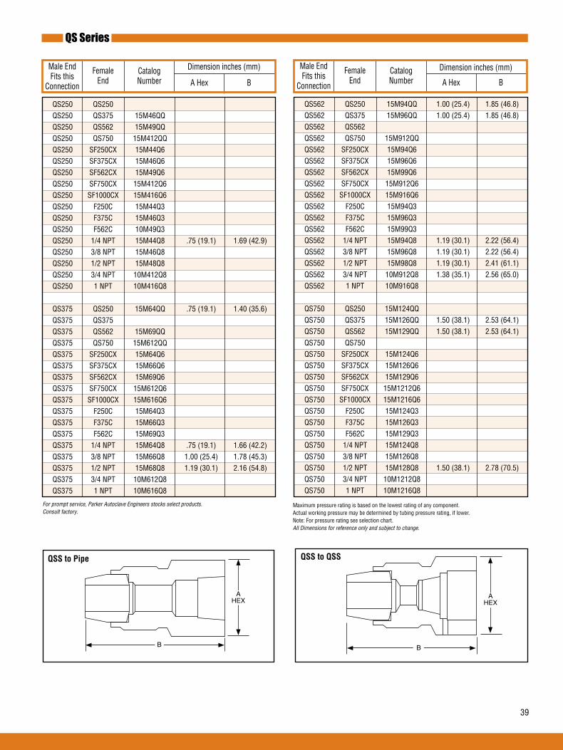
39
QS Series
Female End
Male End Fits this
Connection
CatalogNumber
Dimension inches (mm)
A Hex BFemale
EndCatalogNumber
Dimension inches (mm)
A Hex B
For prompt service, Parker Autoclave Engineers stocks select products. Consult factory.
Maximum pressure rating is based on the lowest rating of any component. Actual working pressure may be determined by tubing pressure rating, if lower.Note: For pressure rating see selection chart.All Dimensions for reference only and subject to change.
Male End Fits this
Connection
AHEX
B
AHEX
B
QSStoPipe QSStoQSS
QS250 QS250 QS250 QS375 15M46QQ QS250 QS562 15M49QQ QS250 QS750 15M412QQ QS250 SF250CX 15M44Q6 QS250 SF375CX 15M46Q6 QS250 SF562CX 15M49Q6 QS250 SF750CX 15M412Q6 QS250 SF1000CX 15M416Q6 QS250 F250C 15M44Q3 QS250 F375C 15M46Q3 QS250 F562C 10M49Q3 QS250 1/4 NPT 15M44Q8 .75 (19.1) 1.69 (42.9) QS250 3/8 NPT 15M46Q8 QS250 1/2 NPT 15M48Q8 QS250 3/4 NPT 10M412Q8 QS250 1 NPT 10M416Q8 QS375 QS250 15M64QQ .75 (19.1) 1.40 (35.6) QS375 QS375 QS375 QS562 15M69QQ QS375 QS750 15M612QQ QS375 SF250CX 15M64Q6 QS375 SF375CX 15M66Q6 QS375 SF562CX 15M69Q6 QS375 SF750CX 15M612Q6 QS375 SF1000CX 15M616Q6 QS375 F250C 15M64Q3 QS375 F375C 15M66Q3 QS375 F562C 15M69Q3 QS375 1/4 NPT 15M64Q8 .75 (19.1) 1.66 (42.2) QS375 3/8 NPT 15M66Q8 1.00 (25.4) 1.78 (45.3) QS375 1/2 NPT 15M68Q8 1.19 (30.1) 2.16 (54.8) QS375 3/4 NPT 10M612Q8 QS375 1 NPT 10M616Q8
QS562 QS250 15M94QQ 1.00 (25.4) 1.85 (46.8) QS562 QS375 15M96QQ 1.00 (25.4) 1.85 (46.8) QS562 QS562 QS562 QS750 15M912QQ QS562 SF250CX 15M94Q6 QS562 SF375CX 15M96Q6 QS562 SF562CX 15M99Q6 QS562 SF750CX 15M912Q6 QS562 SF1000CX 15M916Q6 QS562 F250C 15M94Q3 QS562 F375C 15M96Q3 QS562 F562C 15M99Q3 QS562 1/4 NPT 15M94Q8 1.19 (30.1) 2.22 (56.4) QS562 3/8 NPT 15M96Q8 1.19 (30.1) 2.22 (56.4) QS562 1/2 NPT 15M98Q8 1.19 (30.1) 2.41 (61.1) QS562 3/4 NPT 10M912Q8 1.38 (35.1) 2.56 (65.0) QS562 1 NPT 10M916Q8 QS750 QS250 15M124QQ QS750 QS375 15M126QQ 1.50 (38.1) 2.53 (64.1) QS750 QS562 15M129QQ 1.50 (38.1) 2.53 (64.1) QS750 QS750 QS750 SF250CX 15M124Q6 QS750 SF375CX 15M126Q6 QS750 SF562CX 15M129Q6 QS750 SF750CX 15M1212Q6 QS750 SF1000CX 15M1216Q6 QS750 F250C 15M124Q3 QS750 F375C 15M126Q3 QS750 F562C 15M129Q3 QS750 1/4 NPT 15M124Q8 QS750 3/8 NPT 15M126Q8 QS750 1/2 NPT 15M128Q8 1.50 (38.1) 2.78 (70.5) QS750 3/4 NPT 10M1212Q8 QS750 1 NPT 10M1216Q8

40
SF562CX QS250 15M94KQ .94 (23.8) 1.75 (44.5) SF562CX QS375 15M96KQ .94 (23.8) 1.75 (44.5) SF562CX QS562 15M99KQ 1.38 (34.9) 2.50 (63.5) SF562CX QS750 15M912KQ 1.50 (38.1) 3.25 (82.6)
SF750CX QS250 15M124KQ SF750CX QS375 15M126KQ SF750CX QS562 15M129KQ 1.38 (34.9) 2.67 (67.8) SF750CX QS750 15M1212KQ 1.50 (38.1) 3.06 (77.7)
SF1000CX QS250 15M164KQ SF1000CX QS375 15M166KQ SF1000CX QS562 15M169KQ 1.50 (38.1) 2.88 (73.0) SF1000CX QS750 15M1612KQ 1.50 (38.1) 3.38 (85.7)
Maximum pressure rating is based on the lowest rating of any component. Actual working pressure may be determined by tubing pressure rating, if lower.Note: For pressure rating see selection chart.All Dimensions for reference only and subject to change.Adapter configurations may vary from outline shown.
For prompt service, Parker Autoclave Engineers stocks select products. Consult factory.
F375C QS250 15M64BQ F375C QS375 15M66BQ F375C QS562 15M69BQ F375C QS750 15M612BQ
F562C QS250 15M94BQ 1.19 (30.1) 1.81(46.1) F562C QS375 15M96BQ 1.19 (30.1) 1.69 (42.9) F562C QS562 15M99BQ 1.38 (34.9) 2.32 (58.8) F562C QS750 15M912BQ
F250C QS250 15M44BQ .75 (19.1) 1.31 (33.3) F250C QS375 15M46BQ .81 (20.6) 1.56 (39.7) F250C QS562 15M49BQ F250C QS750 15M412BQ
B
AHEX
MPtoQSS HPtoQSS
B
AHEX
QS Series
Female End
Male End Fits this
Connection
CatalogNumber
Dimension inches (mm)
A Hex BFemale
EndCatalogNumber
Dimension inches (mm)
A Hex B
Male End Fits this
Connection
SF250CX QS250 15M44KQ SF250CX QS375 15M46KQ SF250CX QS562 15M49KQ SF250CX QS750 15M412KQ
SF375CX QS250 15M64KQ SF375CX QS375 15M66KQ .081 (20.6) 1.81 (46.1) SF375CX QS562 15M69KQ SF375CX QS750 15M612KQ 1.50 (38.1) 3.00 (76.2)

41
3/4 NPT QS250 10M124NQ 3/4 NPT QS375 10M126NQ 3/4 NPT QS562 10M129NQ 1.38 (35.1) 2.38 (60.3) 3/4 NPT QS750 10M1212NQ 1.50 (38.1) 2.81 (71.4)
1 NPT QS250 10M164NQ 1 NPT QS275 10M166NQ 1 NPT QS562 10M169NQ 1.50 (38.1) 2.38 (60.3) 1 NPT QS750 10M1612NQ 1.50 (38.1) 2.38 (60.3)
1/4 NPT QS250 15M44NQ 0.75 (19.1) 1.44 (36.5) 1/4 NPT QS375 15M46NQ 0.81 (20.6) 1.63 (41.3) 1/4 NPT QS562 15M49NQ 1/4 NPT QS750 15M412NQ 3/8 NPT QS250 15M64NQ 0.75 (19.1) 1.50 (38.1) 3/8 NPT QS375 15M66NQ 0.81 (20.6) 1.63 (41.3) 3/8 NPT QS562 15M69NQ 1.38 (35.1) 2.13 (53.5) 3/8 NPT QS750 15M612NQ
1/2 NPT QS250 15M84NQ 0.94 (23.8) 1.75 (44.5) 1/2 NPT QS375 15M86NQ 0.94 (23.8) 1.63 (41.3) 1/2 NPT QS562 15M89NQ 1.38 (35.1) 2.25 (57.2) 1/2 NPT QS750 15M812NQ
Maximum pressure rating is based on the lowest rating of any component. Actual working pressure may be determined by tubing pressure rating, if lower.Note: For pressure rating see selection chart.All Dimensions for reference only and subject to change.Adapter configurations may vary from outline shown.
For prompt service, Parker Autoclave Engineers stocks select products. Consult factory.
B
AHEX
NPTtoQSS
QS Series
Female End
Male End Fits this
Connection
CatalogNumber
Dimension inches (mm)
A Hex B

42
QS Series
Parker Autoclave Engineer’s standard male-to-male one piece adapters are available in multiple configurations. Standard male-to-male adapters are machined from cold worked stainless steel.Contact your local Sales Representative for optional information. The following tables list our standard adapters with dimensions.
Adapter End Configuration
QS Series ‘H’ High Pressure ‘RH’ Reverse High Pressure
‘M’ Medium Pressure
Ordering Procedure
Typical catalog number: 15 MA Q4 H9
15
Pressure(X1000psi)
MAMaleAdapter
Q4
M4- 1/4” Medium PressureM6- 3/8” Medium PressureM9 - 9/16” Medium PressureM12 - 3/4” Medium PressureM16- 1” Medium Pressure
H9
P4- 1/4” NPTP6- 3/8” NPTP8 - 1/2” NPTP12 - 3/4” NPTP16- 1” NPT
AvailableEndConnections
Q4- 1/4” QS SeriesQ6- 3/8” QS SeriesQ9- 9/16” QS SeriesQ12- 3/4” QS Series
‘P’ National Pipe Tapered
H4- 1/4” High PressureH5- 5/16” High PressureH6- 3/8” High PressureH9 - 9/16” High Pressure
* RH9 - 9/16” -18 Reverse High RH12 - 3/4” -16 Reverse High RH14- 7/8” -14 Reverse High RH16- 1” -12 Reverse High RH21 - 1-5/16” -12 Reverse High
*RH9 & RH14 - 40,000 psi (2758 bar), RH12 - 30,000 psi (2068 bar), RH16 - 26,000 psi (1793 bar), RH21 - 20,000 psi (1379 bar).

43
Catalog Number
ConnectionRH
Dimension inches (mm)
A Hex B
QS Series to Reverse High-Pressure Adapters
Connection QS
15MAQ4RH9 QS250 9/16” 0.63 (15.9) 1.70 (43.2) 15MAQ6RH9 QS375 9/16” .75 (19.1) 1.81 (46.2) 15MAQ9RH9 QS562 9/16” 1.19 (30.1) 2.25 (57.1) 15MAQ9RH12 QS562 3/4” 1.19 (30.1) 2.38 (60.3) 15MAQ9RH16 QS562 1” 1.19 (30.1) 2.56 (65.1)
A
B
Catalog Number
Dimension inches (mm)
A Hex BConnection
QS
15MAQ9H4 QS562 1/4” 0.75 (19.1) 2.00 (50.8)
A
B
QS Series to High-Pressure Adapter
ConnectionH/P
Catalog Number
Dimension inches (mm)
A Hex BConnection
QS
15MAQ6P4 QS375 1/4” 1.19 (30.1) 2.44 (62.0)
QS Series to NPT Adapter
ConnectionNPT
A
B
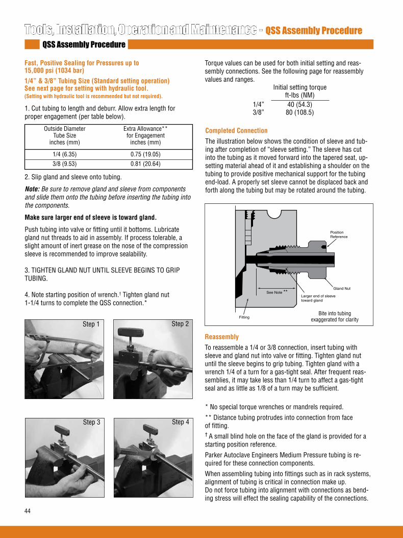
44
1. Cut tubing to length and deburr. Allow extra length for proper engagement (per table below).
2. Slip gland and sleeve onto tubing.
Note: Be sure to remove gland and sleeve from components and slide them onto the tubing before inserting the tubing into the components.
Makesurelargerendofsleeveistowardgland.
Push tubing into valve or fitting until it bottoms. Lubricate gland nut threads to aid in assembly. If process tolerable, a slight amount of inert grease on the nose of the compression sleeve is recommended to improve sealability.
3. TIGHTEN GLAND NUT UNTIL SLEEVE BEGINS TO GRIP TUBING.
4. Note starting position of wrench.† Tighten gland nut 1-1/4 turns to complete the QSS connection.*
Outside Diameter Extra Allowance** Tube Size for Engagement inches (mm) inches (mm)
1/4 (6.35) 0.75 (19.05)
3/8 (9.53) 0.81 (20.64)
Tools, Installation, Operation and Maintenance - QSS Assembly ProcedureQSS Assembly Procedure
Step 1 Step 2
Step 3 Step 4
CompletedConnection
The illustration below shows the condition of sleeve and tub-ing after completion of “sleeve setting.” The sleeve has cut into the tubing as it moved forward into the tapered seat, up-setting material ahead of it and establishing a shoulder on the tubing to provide positive mechanical support for the tubing end-load. A properly set sleeve cannot be displaced back and forth along the tubing but may be rotated around the tubing.
Larger end of sleeve toward gland
Gland Nut
Fitting
See Note **
PositionReference
Bite into tubing exaggerated for clarity
Reassembly
To reassemble a 1/4 or 3/8 connection, insert tubing with sleeve and gland nut into valve or fitting. Tighten gland nut until the sleeve begins to grip tubing. Tighten gland with a wrench 1/4 of a turn for a gas-tight seal. After frequent reas-semblies, it may take less than 1/4 turn to affect a gas-tight seal and as little as 1/8 of a turn may be sufficient.
Fast,PositiveSealingforPressuresupto 15,000psi(1034bar)1/4”&3/8”TubingSize(Standardsettingoperation)Seenextpageforsettingwithhydraulictool.(Settingwithhydraulictoolisrecommendedbutnotrequired).
Torque values can be used for both initial setting and reas-sembly connections. See the following page for reassembly values and ranges. Initial setting torque ft-lbs (NM) 1/4” 40 (54.3) 3/8” 80 (108.5)
* No special torque wrenches or mandrels required.
** Distance tubing protrudes into connection from face of fitting.† A small blind hole on the face of the gland is provided for a starting position reference.
Parker Autoclave Engineers Medium Pressure tubing is re-quired for these connection components.
When assembling tubing into fittings such as in rack systems, alignment of tubing is critical in connection make up.Do not force tubing into alignment with connections as bend-ing stress will effect the sealing capability of the connections.
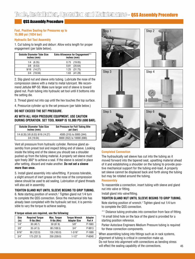
45
1. Cut tubing to length and deburr. Allow extra length for proper engagement (per table below).
2. Slip gland nut and sleeve onto tubing. Lubricate the nose of the compression sleeve with a metal to metal lubricant. We recom-mend Jetlube MP-50. Make sure larger end of sleeve is toward gland nut. Push tubing into hydraulic set tool until it bottoms into the setting die.
3. Thread gland nut into cap until the hex touches the top surface.
4. Pressurize cylinder up to the set pressure (per table below.)
DONOTEXCEEDTHESETPRESSURE.
ASWITHALLHIGHPRESSUREEQUIPMENT,USECAUTIONDURINGOPERATION.SETTOOLMAWPIS10,000PSI(690BAR).
Tools, Installation, Operation and Maintenance - QSS Assembly ProcedureQSS Assembly Procedure
Fast,PositiveSealingforPressuresupto 15,000psi(1034bar)
HydraulicSetToolAssembly
Step 1 Step 2
Step 5 Step 6
Vent all presssure from hydraulic cylinder. Remove gland as-sembly from preset tool and inspect biting end of sleeve. Looking inside the biting end of the sleeve you should see a shoulder pushed up from the tubing material. A properly set sleeve must spin freely 360° to achieve a seal. If the sleeve is seized in place after setting, discard and make another. Donotsetasleevemorethanonce.
5. Install gland assembly into valve/fitting. If process tolerable, a slight amount of inert grease on the nose of the compression sleeve should be used to aid sealing. Lubrication of gland threadswill also aid in assembly.
TIGHTENGLANDNUTUNTILSLEEVEBEGINSTOGRIPTUBING.6. Note starting position of wrench.† Tighten gland nut 1/4 turn to complete the QSS connection. Since the mechanical bite has already been completed with the hydraulic set tool, it is permis-sible to vary the torque to achieve sealing.
Step 3 Step 4
CompletedConnectionThe hydraulically set sleeve has cut into the tubing as it moved forward into the tapered seat, upsetting material ahead of it and establishing a shoulder on the tubing to provide posi-tive mechanical support for the tubing end-load. A properly set sleeve cannot be displaced back and forth along the tubing but may be rotated around the tubing.ReassemblyTo reassemble a connection, insert tubing with sleeve and gland nut into valve or fitting. Install gland into valve/fitting.TIGHTENGLANDNUTUNTILSLEEVEBEGINSTOGRIPTUBING.Note starting position of wrench.† Tighten gland nut 1/4 turn to complete the QSS connection.
** Distance tubing protrudes into connection from face of fitting.† A small blind hole on the face of the gland is provided for a starting position reference.Parker Autoclave Engineers Medium Pressure tubing is required for these connection components.
Iftorquevaluesarerequired,usethefollowing: Size RequiredTorque Max.Torque TorqueWrench Adapter (in) ft-lbs(Nm) ft-lbs(Nm) AdapterSize Part# 1/4” 30 (40.7) 50 (67.8) 5/8” P-1683
3/8” 35 (47.5) 80 (108.5) 3/4” P-9813
9/16” 90 (122.0) 135 (183.0) 1-3/16” P-1689
3/4” 175 (237.3) 250 (339.0) 1-1/2” P-6040
OutsideDiameterTubeSize ExtraAllowanceforEngagement** inches(mm) inches(mm)
1/4 (6.35) 0.75 (19.05) 3/8 (9.53) 0.81 (20.64) 9/16 (14.27) 1.25 (31.75) 3/4 (19.04) 1.63 (41.28)
When assembling tubing into fittings such as in rack systems, alignment of tubing is critical in connection make up. Do not force into alignment with connections as bending stress will effect the sealing capability of the connections.
OutsideDiameterTubeSize SetPressureforFullTubingBite inches(mm) psi(bar)
1/4 (6.35) 3/8 (9.53) 9/16 (14.27) 4500 (310) to 5000 (344) 3/4 (19.04) 8000 (552) to 10000 (690)

46
Tools, Installation, Operation and Maintenance - Hydraulic Sleeve Set ToolHydraulic Sleeve Set Tool
The Parker Autoclave Engineers hydraulic sleeve set tool is designed for use with the QS Series glands, sleeves and Parker Autoclave Engineers tubing. This tool is required to set the sleeve for the 9/16” and 3/4” sizes and suggested for the 1/4” and 3/8” sizes. It not only produces the required bite into the tubing, it is much easier than trying to set the sleeve the conventional method.
The tool comes in a self contained portable, lockable casecomplete with hand or air pump, cap and dies for all sizes.
Features
CaseDimensions: 28”W x 14.25”H x 13.75”D (711cm x 362cm x 292cm)
TotalWeight: 69 lbs. (31 Kg)
HandPump:Single stage hydraulic (standard)
HydraulicCylinder:10,000 psi, 2.5” 25 ton
Base&Housing:Aluminum anodized
DieandCap:Precision hardened steel
Gauge:15,000 psi (1034 bar)
Air-operatedhydraulicpumpoptioncan be furnished in place of standard hand pump. (Add “-A” to order number). Operating pressure 0 to 10,000 psi (0 to 690 bar). Required air presssure, 30 psi (2.1 bar) minimum 120 psi (8.3 bar) maximum. Reservoir capacity: 24 cu. in. (393cm3). Air lubricator/air separator is recommended for air operated units.
Cap
Die
Housing
HydraulicCylinder
Base
Hose Connection3/8” NPT
ToolingInstallationandChangingSizes
To change tooling to another size only requires interchanging 2 parts.
1. Loosen the 5/16" set screw that locks the threaded cap from rotating.
2. Using a 5/32" hex key to rotate and remove the threaded steel cap from the aluminum housing.
3. Turn the tool assembly upside down the remove the die from inside the housing.
4. Install the die of the appropriate connection size you wish to use. The solid side of the die should be facing down towards the hydraulic cylinder.
5. Install the appropriate size cap to match the size of the die. Insert cap with the 5/32" hex up. Rotate with a 5/32" hex key until it bottoms out on the shoulder side of the housing.
6. Thread in the 5/16" set screw until it bottoms out on the cap threads. Tighten set screw to prevent movement during use.
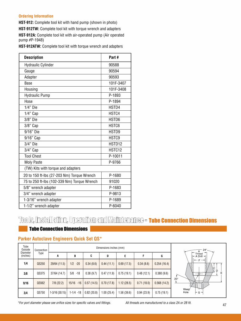
47
OrderingInformation
HST-912: Complete tool kit with hand pump (shown in photo)
HST-912TW: Complete tool kit with torque wrench and adapters
HST-912A: Complete tool kit with air-operated pump (Air operated pump #P-1948)
HST-912ATW: Complete tool kit with torque wrench and adapters
Description Part#
20 to 150 ft-lbs (27-203 Nm) Torque Wrench P-168075 to 250 ft-lbs (102-339 Nm) Torque Wrench 910205/8” wrench adapter P-16833/4” wrench adapter P-98131-3/16” wrench adapter P-16891-1/2” wrench adapter P-6040
1/4” Die HSTD4 1/4” Cap HSTC4 3/8” Die HSTD6 3/8” Cap HSTC6
Hydraulic Cylinder 90588 Gauge 90594 Adapter 90593 Base 101F-3407 Housing 101F-3408 Hydraulic Pump P-1893 Hose P-1894
9/16” Die HSTD9 9/16” Cap HSTC9 3/4” Die HSTD12 3/4” Cap HSTC12 Tool Chest P-10011 Moly Paste P-9766 (TW) Kits with torque and adapters
Tools, Installation, Operation and Maintenance - Tube Connection DimensionsTube Connection Dimensions
ParkerAutoclaveEngineersQuickSetQS*
1/4
ConnectionType
3/8
9/16
3/4
A B C D E F
Dimensions inches (mm)
QS250 29/64 (11.5) 1/2 -20 0.34 (8.6) 0.44 (11.1) 0.69 (17.5) 0.34 (8.6) 0.254 (16.4)
QS375 37/64 (14.7) 5/8 -18 0.38 (9.7) 0.47 (11.9) 0.75 (19.1) 0.48 (12.1) 0.380 (9.6)
QS562 7/8 (22.2) 15/16 -16 0.57 (14.5) 0.70 (17.8) 1.12 (28.5) 0.71 (18.0) 0.568 (14.2)
QS750 1-3/16 (30.15) 1-1/4 -18 0.82 (20.8) 1.00 (25.4) 1.56 (39.6) 0.94 (23.9) 0.75 (19.1)
TubeOutside
Diameter(inches) G
*
('
&
)$ ' ULOOUU
%7KUHDG
WeepHole
*For port diameter please see orifice sizes for specific valves and fittings. All threads are manufactured to a class 2A or 2B fit.

02-1253BE January2013© 2013 Parker Hannifin Corporation | Autoclave Engineers is a registered trademark of the Parker Hannifin Corporation
Parker Hannifin Manufacturing Ltd. InstrumentationProductsDivision,Europe Industrial Estate WhitemillWexford, Republic of IrelandPH: 353 53 914 1566FAX: 353 53 914 1582
InstrumentationProductsDivisionAutoclave Engineers Operation8325 Hessinger DriveErie, Pennsylvania 16509-4679 USAPH: 814-860-5700 FAX: 814-860-5811www.autoclave.com
WARNINGFAILURE,IMPROPERSELECTIONORIMPROPERUSEOFTHEPRODUCTSAND/ORSYSTEMSDESCRIBEDHEREINORRELATEDITEMSCANCAUSEDEATH,PERSONALINJURYANDPROPERTYDAMAGE.This document and other information from Parker Hannifin Corporation, its subsidiaries and authorized distributors provide product and/or system options for further investigation by users having technical expertise. It is important that you analyze all aspects of your application and review the information concerning the product or system in the current product catalog. Due to the variety of operating conditions and applications for these products or systems, the user, through its own analysis and testing, is solely responsible for making the final selection of the products and systems and assuring that all performance, safety and warning requirements of the application are met. The products described herein, including without limitation, product features, specifications, designs, availability and pricing, are subject to change by Parker Hannifin Corporation and its subsidiaries at any time without notice.
Offer of SaleThe items described in this document are available for sale by Parker Hannifin Corporation, its subsidiaries or its authorized distributors. Any sale contract entered by Parker will be governed by the provisions stated in Parker's standard terms and conditions of sale (copy available upon request).
ISO-9001 Certified
Caution! Do not mix or interchange parts or tubing with those of other manufacturers. Doing so is unsafe and will void warranty.
Caution! Parker Autoclave Engineers Valves, Fittings and Tools are not designed to work with common commercial instrument tubing and will only work with tubing built to Parker Autoclave Engineers AES Specifications. Failure to do so will void warranty.
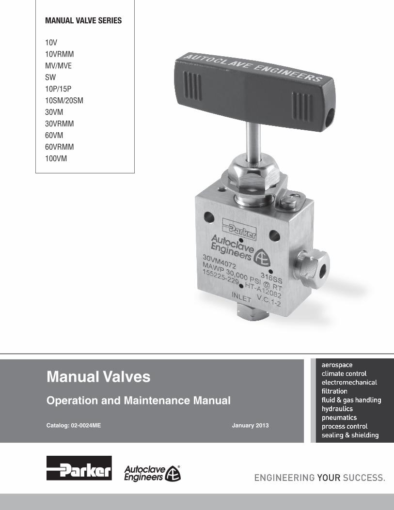
MANUAL VALVE SERIES
10V10VRMMMV/MVESW10P/15P10SM/20SM30VM30VRMM60VM60VRMM100VM
Manual ValvesOperation and Maintenance Manual
Catalog: 02-0024ME January 2013
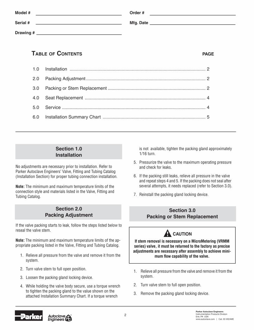
2Parker Autoclave EngineersInstrumentation Products DivisionErie, PA USAwww.autoclave.com | Cat. 02-0024ME
Table of ConTenTs page
1.0 Installation ........................................................................................................... 2
2.0 Packing Adjustment .............................................................................................. 2
3.0 Packing or Stem Replacement ............................................................................. 2
4.0 Seat Replacement ............................................................................................... 4
5.0 Service ................................................................................................................. 4
6.0 Installation Summary Chart ................................................................................. 5
If stem removal is necessary on a MicroMetering (VRMM series) valve, it must be returned to the factory as precise
adjustments are necessary after assembly to achieve mini-mum flow capability of the valve.
! CAUTION
Section 1.0Installation
No adjustments are necessary prior to installation. Refer to Parker Autoclave Engineers’ Valve, Fitting and Tubing Catalog (Installation Section) for proper tubing connection installation. Note: The minimum and maximum temperature limits of the connection style and materials listed in the Valve, Fitting and Tubing Catalog.
Section 2.0Packing Adjustment
If the valve packing starts to leak, follow the steps listed below to reseal the valve stem.
Note: The minimum and maximum temperature limits of the ap-propriate packing listed in the Valve, Fitting and Tubing Catalog. 1. Relieve all pressure from the valve and remove it from the system.
2. Turn valve stem to full open position.
3. Loosen the packing gland locking device.
4. While holding the valve body secure, use a torque wrench to tighten the packing gland to the value shown on the attached Installation Summary Chart. If a torque wrench
is not available, tighten the packing gland approximately 1/16 turn.
5. Pressurize the valve to the maximum operating pressure and check for leaks.
6. If the packing still leaks, relieve all pressure in the valve and repeat steps 4 and 5. If the packing does not seal after several attempts, it needs replaced (refer to Section 3.0).
7. Reinstall the packing gland locking device.
Section 3.0Packing or Stem Replacement
1. Relieve all pressure from the valve and remove it from the system.
2. Turn valve stem to full open position.
3. Remove the packing gland locking device.
Model # Order #
Serial # Mfg. Date
Drawing #

3Parker Autoclave EngineersInstrumentation Products DivisionErie, PA USAwww.autoclave.com | Cat. 02-0024ME
4. While holding the valve body (or housing for HT and LT valves) secure, unthread and remove the packing gland. The packing will stay on stems that have a larger stem tip below the packing (see Fig. 3: SW8, 10/20SM9, 10/20SM12, 10/20SM16).
Note: For HT and LT valves, the housing must be removed where the stem tip is larger than the body cone ring ID (SW6, SM12 and SM16 valves). Remove the housing locking device and unscrew the housing from the valve body.
5. Autoclave Engineers manual valves have three different type of stems; one piece non-rotating (figure 2), two piece pinned non-rotating (figure 4) and rotating (figure 5). Follow steps 6-9 for one piece non-rotating stems, steps 10-11 for two piece pinned non-rotating stems and step 12 for rotating stems.
One piece non-rotating stem
6. For stems without a larger stem tip, remove the bottom washer, packing and packing washer in the body. Place the bottom washer, packing and packing washer in the body. If the stem does not require replacement, screw the packing gland back into the body and tighten the packing gland to the value in the Installation Sum- mary Chart.
7. Remove the handle by loosening the set screw(s) located in the larger hole of the handle (use a 5/32 hex wrench for the 3" long handle, a 3/16 hex wrench for the 4" and 10-1/4" long handle) and remove it from the stem sleeve. Unscrew the stem from the packing gland. Remove the two nuts and thrust washer from the top of the stem assembly. Remove the stem from the stem sleeve. Remove the bottom thrust washer from the stem. For SW8, 10SM9 and 20SM9 valves, remove the stem collar by unscrewing it clockwise. For stems with a larger stem tip, remove the packing washer and packing from the stem.
8. Clean thrust washers and all surfaces which mate with thrust washers with a clean cloth. Apply non-hardening lubricant (Jet-Lube SS-301 or similar) lightly to both faces of the thrust washer and the sleeve threads.
9. For stems with a larger stem tip, place the bottom washer, packing and packing washer on the stem (remove the bottom washer from from the old stem if the stem is being replaced). For SW8, 10SM9 and 20SM9 valves, place the stem collar on the stem by threading it counter-clockwise. Place first thrust washer on the stem and slide stem into stem sleeve. Place second thrust washer on the stem sleeve. Replace hex nut lightly against the upper thrust washer and thread the stem assembly fully into the packing gland. Screw the packing gland into the body and tighten
to the value in the Installation Summary Chart. Open the valve completely, then close it one turn to remove the play. Finger tighten the hex nut, then use a wrench to tighten it approximately 1/8 of a turn. Install the lock nut and finger tighten it in place. While holding the lock nut secure, loosen the hex nut from the top washer and tighten it against the lock nut approximately 1/16 of a turn. Replace the handle by lining the hex socket set screw up against the flat spot on the stem sleeve and tightenit in place (DO NOT OVERTIGHTEN). In order to have a nonrotating stem, a slight amount of free play must exist between the stem sleeve and shaft. The handle should have a 10 degree maximum free play for "backlash". If the free play is excessive, it will be necessary to remove the handle and loosen the lock nut and tighten the hex nut further against the thrust washer. Tighten the lock nut as indicated above and check for free play. When the desired "backlash" is achieved, replace the handle as described above. Re-install the locking device.
Two piece pinned non-rotating stems
10. For high and low temperature valves that have two piece non-rotating stems, remove the groove pin holding
LOCK NUT
HEX NUT
SECOND THRUST WASHER
STEM SLEEVE
FIRST THRUST WASHER
STEM
Figure 1: Two-Piece Non-rotating Stem Assembly (Exploded)
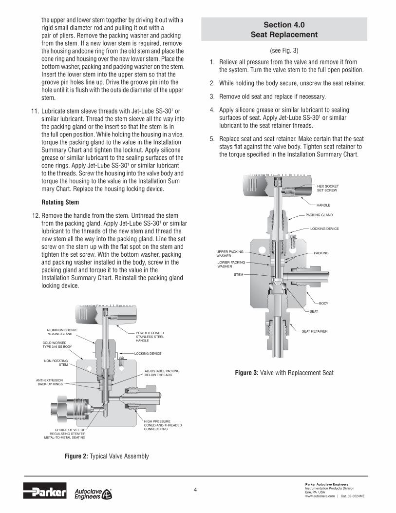
4Parker Autoclave EngineersInstrumentation Products DivisionErie, PA USAwww.autoclave.com | Cat. 02-0024ME
the upper and lower stem together by driving it out with a rigid small diameter rod and pulling it out with a pair of pliers. Remove the packing washer and packing from the stem. If a new lower stem is required, remove the housing andcone ring from the old stem and place the cone ring and housing over the new lower stem. Place the bottom washer, packing and packing washer on the stem. Insert the lower stem into the upper stem so that the groove pin holes line up. Drive the groove pin into the hole until it is flush with the outside diameter of the upper stem.
11. Lubricate stem sleeve threads with Jet-Lube SS-301 or similar lubricant. Thread the stem sleeve all the way into the packing gland or the insert so that the stem is in the full open position. While holding the housing in a vice, torque the packing gland to the value in the Installation Summary Chart and tighten the locknut. Apply silicone grease or similar lubricant to the sealing surfaces of the cone rings. Apply Jet-Lube SS-301 or similar lubricant to the threads. Screw the housing into the valve body and torque the housing to the value in the Installation Sum mary Chart. Replace the housing locking device.
Rotating Stem
12. Remove the handle from the stem. Unthread the stem from the packing gland. Apply Jet-Lube SS-301 or similar lubricant to the threads of the new stem and thread the new stem all the way into the packing gland. Line the set screw on the stem up with the flat spot on the stem and tighten the set screw. With the bottom washer, packing and packing washer installed in the body, screw in the packing gland and torque it to the value in the Installation Summary Chart. Reinstall the packing gland locking device.
Section 4.0Seat Replacement
(see Fig. 3)
1. Relieve all pressure from the valve and remove it from the system. Turn the valve stem to the full open position.
2. While holding the body secure, unscrew the seat retainer.
3. Remove old seat and replace if necessary.
4. Apply silicone grease or similar lubricant to sealing surfaces of seat. Apply Jet-Lube SS-301 or similar lubricant to the seat retainer threads.
5. Replace seat and seat retainer. Make certain that the seat stays flat against the valve body. Tighten seat retainer to the torque specified in the Installation Summary Chart.
ALUMINUM BRONZEPACKING GLAND
COLD WORKED TYPE 316 SS BODY
NON-ROTATINGSTEM
ADJUSTABLE PACKINGBELOW THREADS
LOCKING DEVICE
HIGH PRESSURECONED-AND-THREADED CONNECTIONSCHOICE OF VEE OR
REGULATING STEM TIPMETAL-TO-METAL SEATING
ANTI-EXTRUSIONBACK-UP RINGS
POWDER COATEDSTAINLESS STEELHANDLE
Figure 2: Typical Valve Assembly
Figure 3: Valve with Replacement Seat
LOCKING DEVICE
BODY
SEAT
LOWER PACKING WASHER
HEX SOCKET SET SCREW
HANDLE
STEM
PACKING
SEAT RETAINER
UPPER PACKING WASHER
PACKING GLAND
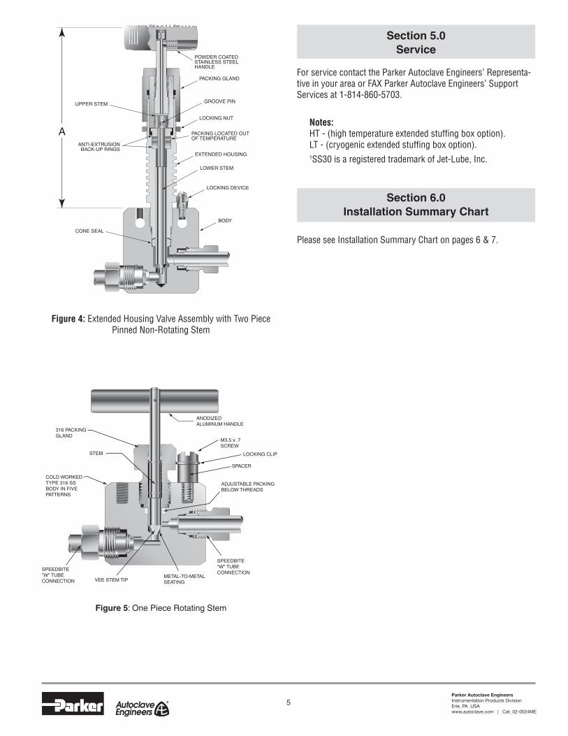
5Parker Autoclave EngineersInstrumentation Products DivisionErie, PA USAwww.autoclave.com | Cat. 02-0024ME
Section 5.0Service
For service contact the Parker Autoclave Engineers’ Representa-tive in your area or FAX Parker Autoclave Engineers’ Support Services at 1-814-860-5703.
Notes: HT - (high temperature extended stuffing box option). LT - (cryogenic extended stuffing box option).
1SS30 is a registered trademark of Jet-Lube, Inc.
Section 6.0Installation Summary Chart
Please see Installation Summary Chart on pages 6 & 7.
LOCKING DEVICE
BODY
LOWER STEM
EXTENDED HOUSING
LOCKING NUT
PACKING GLAND
GROOVE PIN
PACKING LOCATED OUTOF TEMPERATURE
CONE SEAL
UPPER STEM
ANTI-EXTRUSIONBACK-UP RINGS
POWDER COATEDSTAINLESS STEELHANDLE
A
Figure 4: Extended Housing Valve Assembly with Two Piece Pinned Non-Rotating Stem
ANODIZEDALUMINUM HANDLE
STEM
ADJUSTABLE PACKING BELOW THREADS
COLD WORKED TYPE 316 SS BODY IN FIVE PATTERNS
316 PACKING GLAND
VEE STEM TIPMETAL-TO-METAL SEATING
M3.5 x .7SCREW
SPEEDBITE"W" TUBE CONNECTION
LOCKING CLIP
SPACER
SPEEDBITE"W" TUBE CONNECTION
Figure 5: One Piece Rotating Stem
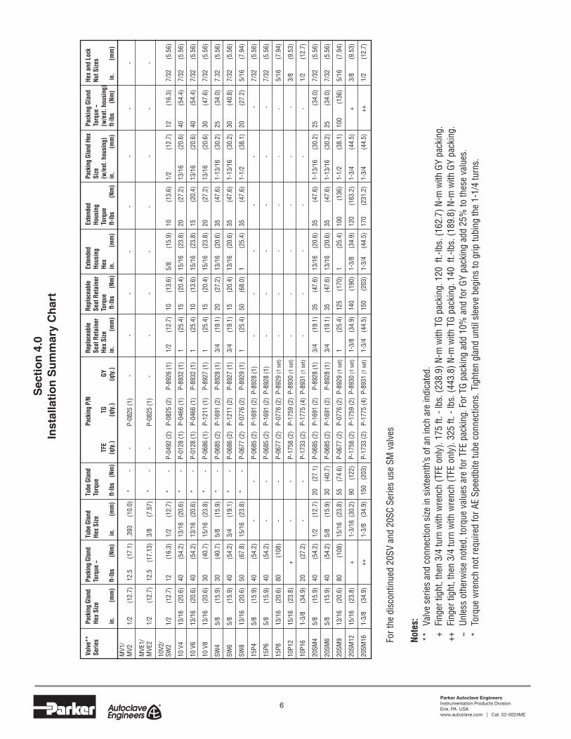
6Parker Autoclave EngineersInstrumentation Products DivisionErie, PA USAwww.autoclave.com | Cat. 02-0024ME
Sec
tio
n 4
.0In
stal
lati
on
Su
mm
ary
Ch
art
For t
he d
isco
ntin
ued
20SV
and
20S
C Se
ries
use
SM v
alve
s
Note
s: *
* V
alve
ser
ies
and
conn
ectio
n si
ze in
six
teen
th’s
of a
n in
ch a
re in
dica
ted.
+
Fin
ger t
ight
, the
n 3/
4 tu
rn w
ith w
renc
h (T
FE o
nly)
. 175
ft. -
lbs.
(238
.9) N
-m w
ith T
G pa
ckin
g. 1
20 f
t.-lb
s. (1
62.7
) N-m
with
GY
pack
ing.
++
Fin
ger t
ight
, the
n 3/
4 tu
rn w
ith w
renc
h (T
FE o
nly)
. 325
ft. -
lbs.
(443
.8) N
-m w
ith T
G pa
ckin
g. 1
40 f
t.-lb
s. (1
89.8
) N-m
with
GY
pack
ing.
~
Unl
ess
othe
rwis
e no
ted,
torq
ue v
alue
s ar
e fo
r TFE
pac
king
. For
TG
pack
ing
add
10%
and
for G
Y pa
ckin
g ad
d 25
% to
thes
e va
lues
.
* To
rque
wre
nch
not r
equi
red
for A
E Sp
eedb
ite tu
be c
onne
ctio
ns. T
ight
en g
land
unt
il sl
eeve
beg
ins
to g
rip tu
bing
the
1-1/
4 tu
rns.
Valv
e**
Pa
ckin
g Gl
and
Pack
ing
Glan
d
Tube
Gla
nd
Tube
Gla
nd
Pac
king
P/N
Re
plac
eabl
e
Repl
acea
ble
Ex
tend
ed
Exte
nded
Pa
ckin
g Gl
and
Hex
Pack
ing
Glan
d
Hex
and
Lock
Serie
s
Hex
Size
To
rque
~
Hex
Size
To
rque
Seat
Ret
aine
r Se
at R
etai
ner
Hous
ing
Ho
usin
g
Size
To
rque
~
Nut S
izes
TF
E
TG
GY
He
x Si
ze
Torq
ue
Hex
To
rque
(w
/ext
. hou
sing
) (w
/ext
. hou
sing
)
in.
(mm
) ft-
lbs
(N
m)
in.
(mm
) ft-
lbs
(N
m)
(qty
.)
(qty
.)
(qty
.)
in.
(mm
) ft-
lbs
(N
m)
in.
(mm
) ft-
lbs
(Nm
) in
. (m
m)
ft-lb
s
(Nm
) in
. (m
m)
MV1
/M
V2
1/2
(1
2.7)
12
.5
(17.
1)
.393
(1
0.0)
*
-
- P
-082
5 (1
) -
-
- -
- -
- -
MVE
1/M
VE2
1/
2
(12.
7)
12.5
(1
7.13
) 3/
8
(7.5
7)
* -
-
P-0
825
(1)
- -
- -
- -
- -
10V2
/SW
2
1/2
(1
2.7)
12
(1
6.3)
1/
2
(12.
7)
* -
P-
0492
(2)
P-08
25 (2
) P-
8926
(1)
1/2
(1
2.7)
10
(1
3.6)
5/
8
(15.
9)
10
(13.
6)
1/2
(12.
7)
12
(16.
3)
7/32
(5
.56)
10 V
4
13/1
6
(20.
6)
40
(54.
2)
13/1
6 (
20.6
) *
-
P-01
28 (1
) P-
0466
(1)
P-89
32 (1
) 1
(2
5.4)
15
(2
0.4)
15
/16
(2
3.8)
20
(2
7.2)
13
/16
(2
0.6)
40
(5
4.4)
7/
32
(5.5
6)
10 V
6
13/1
6
(20.
6)
40
(54.
2)
13/1
6 (
20.6
) *
-
P-01
28 (1
) P-
0466
(1)
P-89
32 (1
) 1
(2
5.4)
10
(1
3.6)
15
/16
(2
3.8)
15
(2
0.4)
13
/16
(2
0.6)
40
(5
4.4)
7/
32
(5.5
6)
10 V
8
13/1
6
(20.
6)
30
(40.
7)
15/1
6 (
23.8
) *
-
P-06
86 (1
) P-
1211
(1)
P-89
27 (1
) 1
(2
5.4)
15
(2
0.4)
15
/16
(2
3.8)
20
(2
7.2)
13
/16
(2
0.6)
30
(4
7.6)
7/
32
(5.5
6)
SW4
5/
8
(15.
9)
30
(40.
7)
5/8
(1
5.9)
*
-
P-06
85 (2
) P-
1691
(2)
P-89
28 (1
) 3/
4 (1
9.1)
20
(2
7.2)
13
/16
(2
0.6)
35
(4
7.6)
1-
13/1
6
(30.
2)
25
(34.
0)
7.32
(5
.56)
SW6
5/
8
(15.
9)
40
(54.
2)
3/4
(1
9.1)
*
-
P-06
86 (2
) P-
1211
(2)
P-89
27 (1
) 3/
4
(19.
1)
15
(20.
4)
13/1
6
(20.
6)
35
(47.
6)
1-13
/16
(3
0.2)
30
(4
0.8)
7/
32
(5.5
6)
SW8
13
/16
(2
0.6)
50
(6
7.8)
15
/16
(23
.8)
* -
P-
0677
(2)
P-07
76 (2
) P-
8929
(1)
1
(25.
4)
50
(68.
0)
1
(25.
4)
35
(47.
6)
1-1/
2
(38.
1)
20
(27.
2)
5/16
(7
.94)
15P4
5/
8 (1
5.9)
40
(
54.2
)
-
-
P-
0685
(2)
P-16
91 (2
) P-
8928
(1)
-
-
-
-
-
-
7/32
(5
.56)
15P6
5/
8
(15.
9)
40
(54
.2)
-
-
P-06
85 (2
) P-
1691
(2)
P-89
28 (1
)
-
-
-
-
-
- 7/
32
(5.5
6)
15P8
13
/16
(2
0.6)
80
(108
)
-
-
P-
0677
(2)
P-07
76 (2
) P-
8929
(1 s
et)
-
-
-
-
-
-
5/16
(7
.94)
10P1
2
15/1
6
(23.
8)
+
-
-
P-17
58 (2
) P-
1759
(2)
P-89
30 (1
set
)
-
-
-
-
-
- 3/
8 (9
.53)
10P1
6
1-3/
8
(34.
9)
20
(27
.2)
-
-
P-17
33 (2
) P-
1775
(4)
P-89
31 (1
set
)
-
-
-
-
-
- 1/
2
(12.
7)
20SM
4
5/8
(15.
9)
40
(54.
2)
1/2
(1
2.7)
20
(2
7.1)
P-
0685
(2)
P-16
91 (2
) P-
8928
(1)
3/4
(1
9.1)
35
(4
7.6)
13
/16
(2
0.6)
35
(4
7.6)
1-
13/1
6
(30.
2)
25
(34.
0)
7/32
(5
.56)
20SM
6
5/8
(1
5.9)
40
(5
4.2)
5/
8 (1
5.9)
30
(4
0.7)
P-
0685
(2)
P-16
91 (2
) P-
8928
(1)
3/4
(1
9.1)
35
(4
7.6)
13
/16
(2
0.6)
35
(4
7.6)
1-
13/1
6
(30.
2)
25
(34.
0)
7/32
(5
.56)
20SM
9
13/1
6
(20.
6)
80
(108
) 15
/16
(23
.8)
55
(74.
6)
P-06
77 (2
) P-
0776
(2)
P-89
29 (1
set
) 1
(2
5.4)
12
5
(170
) 1
(2
5.4)
10
0
(136
) 1-
1/2
(3
8.1)
10
0
(136
) 5/
16
(7.9
4)
20SM
12
15/1
6
(23.
8)
+
1-3/
16 (
30.2
) 90
(1
22)
P-17
58 (2
) P-
1759
(2)
P-89
30 (1
set
) 1-
3/8
(3
4.9)
14
0
(190
) 1-
3/8
(3
4.9)
12
0
(163
.2)
1-3/
4
(44.
5)
+
3/8
(9.5
3)
20SM
16
1-3/
8
(34.
9)
++
1-3/
8
(34.
9)
150
(20
3)
P-17
33 (2
) P-
1775
(4)
P-89
31 (1
set
) 1-
3/4
(4
4.5)
15
0
(203
) 1-
3/4
(4
4.5)
17
0
(231
.2)
1-3/
4 (4
4.5)
++
1/
2
(12.
7)

7Parker Autoclave EngineersInstrumentation Products DivisionErie, PA USAwww.autoclave.com | Cat. 02-0024ME
Inst
alla
tio
n S
um
mar
y C
har
t -
con
't
Note
s: *
* V
alve
ser
ies
and
conn
ectio
n si
ze in
six
teen
th’s
of a
n in
ch a
re in
dica
ted.
^
Zero
pos
ition
of b
arre
l or t
him
ble
mus
t be
chan
ged.
^
60VM
and
60V
RMM
pac
king
is n
ylon
(P-0
829)
, lea
ther
(P-0
803)
and
nyl
on (P
-082
9).
+
Fin
ger t
ight
, the
n 3/
4 tu
rn w
ith w
renc
h (T
FE o
nly)
. 175
ft. -
lbs.
(238
.9) N
-m w
ith T
G pa
ckin
g. 1
20 f
t.-lb
s. (1
62.7
) N-m
with
GY
pack
ing.
++
Fin
ger t
ight
, the
n 3/
4 tu
rn w
ith w
renc
h (T
FE o
nly)
. 325
ft. -
lbs.
(443
.8) N
-m w
ith T
G pa
ckin
g. 1
40 f
t.-lb
s. (1
89.8
) N-m
with
GY
pack
ing.
~
Unl
ess
othe
rwis
e no
ted,
torq
ue v
alue
s ar
e fo
r TFE
pac
king
. For
TG
pack
ing
add
10%
and
for G
Y pa
ckin
g ad
d 25
% to
thes
e va
lues
.
* To
rque
wre
nch
not r
equi
red
for A
E Sp
eedb
ite tu
be c
onne
ctio
ns. T
ight
en g
land
unt
il sl
eeve
beg
ins
to g
rip tu
bing
the
1-1/
4 tu
rns.
N/A
Not
App
licab
le
Valv
e**
Pa
ckin
g Gl
and
Pack
ing
Glan
d
Tube
Gla
nd
Tube
Gla
nd
Pac
king
P/N
Re
plac
eabl
e
Repl
acea
ble
Ex
tend
ed
Exte
nded
Pa
ckin
g Gl
and
Hex
Pack
ing
Glan
d
Hex
and
Lock
Serie
s
Hex
Size
To
rque
~
Hex
Size
To
rque
Seat
Ret
aine
r Se
at R
etai
ner
Hous
ing
Ho
usin
g
Size
To
rque
~
Nut S
izes
TF
E
TG
GY
He
x Si
ze
Torq
ue
Hex
To
rque
(w
/ext
. hou
sing
) (w
/ext
. hou
sing
)
in.
(mm
) ft-
lbs
(N
m)
in.
(mm
) ft-
lbs
(Nm
) (q
ty.)
(q
ty.)
(q
ty.)
in
. (m
m)
ft-lb
s
(Nm
) in
. (m
m)
ft-lb
s (N
m)
in.
(mm
) ft-
lbs
(N
m)
in.
(mm
)
^^
30VM
4
13/1
6
(20.
6)
60
(81.
3)
5/8
(1
5.9)
15
(2
0.3)
P-
0128
(1)
P-04
66 (1
) P-
8932
(1)
3/4
(1
9.1)
35
(4
7.6)
15
/16
(2
3.8)
50
(6
7.8)
13
/16
(2
0.6)
60
(8
1.3)
7/
32
(5.5
6)
30VM
6
13/1
6
(20.
6)
60
(81.
3)
13/1
6 (
20.6
) 25
(3
3.9)
P-
0128
(1)
P-04
66 (1
) P-
8932
(1)
1
(25.
4)
35
(47.
6)
15/1
6
(23.
8)
50
(67.
8)
13/1
6
(20.
6)
60
(81.
3)
7/32
(5
.56)
30VM
9
13/1
6
(20.
6)
60
(81.
3)
1-3/
16 (
30.2
) 55
(7
4.6)
P-
0128
(1)
P-04
66 (1
) P-
8932
(1)
1-3/
8
(34.
9)
35
(47.
6)
15/1
6
(23.
8)
50
(67.
8)
13/1
6
(20.
6)
60
(81.
3)
7/32
(5
.56)
60VM
4 13
/16
(2
0.6)
60
(8
1.3)
5/
8
(15.
9)
25
(33.
9)
P-08
64
P-
8713
(2)
P-89
33 (1
) 13
/16
(20.
6)
45
(61.
2)
15/1
6
(23.
8)
65
(88.
1)
13/1
6
(20.
6)
60
(81.
3)
7.32
(5
.56)
(1
set
)
60VM
6 13
/16
(2
0.6)
60
(8
1.3)
13
/16
(20
.6)
50
(67.
8)
P-08
64
P-87
13 (2
) P-
8933
(1)
1
(25.
4)
45
(61.
2)
15/1
6
(23.
8)
65
(88.
1)
13/1
6
(20.
6)
60
(81.
3)
7/32
(5
.56)
(1
set
)
60VM
9 13
/16
(2
0.6)
60
(8
1.3)
1-
3/16
(30
.2)
110 (
149.
2)
P-08
64
P-87
13 (2
) P-
8933
(1)
1-3/
8
(34.
9)
45
(61.
2)
15/1
6
(23.
8)
65
(88.
1)
13/1
6
(20.
6)
60
(81.
3)
7/32
(5
.56)
(1
set
)
10VR
MM
2 5/
8 (1
5.9)
20
^
(27.
1)
1/2
(1
2.7)
*
P-1
654
(1)
P-0
467
(1)
P-89
34 (1
) 5/
8
(15.
9)
25
(34.
0)
5/8
(1
5.9)
15
(2
0.5)
5/
8
(15.
9)
20
(27.
3)
N/A
30VR
MM
4 13
/16
(2
0.6)
50
^
(67.
8)
5/8
(15.
9)
15
(20.
3)
P-16
54 (1
) P-
0467
(1)
P-89
34 (1
) 13
/16
(20.
6)
50
(67.
8)
15/1
6
(23.
8)
50
(67.
8)
13/1
6
(20.
6)
50
(67.
8)
N/A
60VR
MM
4 13
/16
(2
0.6)
50
^
(67.
8)
5/8
(15.
9)
25
(33.
9)
P-08
64 (1
) P-
8713
(2)
P-89
33 (1
) 15
/16
(23
.8)
35
(47.
6)
N/A
N/
A
N/A
N/
A 7/
32
(5.5
6)
(1 s
et)
60VR
MM
4 1
3/16
(2
0.6)
50
^
(67.
8)
13/1
6 (
20.6
) 50
(6
7.8)
P-
0864
(1)
P-87
13 (2
) P-
8933
(1)
1-3/
8
(34.
9)
35
(47.
6)
15/1
6
(23.
8)
55
(75.
1)
13/1
6
(20.
6)
75
(102
.4)
7/32
(5
.56)
(1
set
)
100V
M5
15/1
6
(23.
8)
60
(81.
3)
3/4
(1
9.1)
70
(9
5.0)
90
368
(1)
N/
A
70
(9
5.2)
N
A
N/A
NA
N/A
15
/16
(7.9
4)
9036
9 (2
)
100V
M4
15/1
6
(23.
8)
60
(81.
3)
3/4
(1
9.1)
70
(9
5.0)
90
368
(1)
1
(25.
4)
70
(95.
2)
NA
N/A
NA
N/A
15
/16
(7.9
4)
9036
9 (2
)
100V
M6
15/1
6
(23.
8)
60
(81.
3)
3/4
(1
9.1)
70
(9
5.0)
90
368
(1)
1
(25.
4)
70
(95.
2)
NA
N/A
NA
N/A
15
/16
(7.9
4)
9036
9 (2
)

ISO-9001 Certified
02-0024ME January 2013© 2013 Parker Hannifin Corporation | Autoclave Engineers is a registered trademark of the Parker Hannifin Corporation
Parker Hannifin Manufacturing Ltd. Instrumentation Products Division, Europe Industrial Estate WhitemillWexford, Republic of IrelandPH: 353 53 914 1566FAX: 353 53 914 1582
Instrumentation Products DivisionAutoclave Engineers Operation8325 Hessinger DriveErie, Pennsylvania 16509-4679 USAPH: 814-860-5700 FAX: 814-860-5811www.autoclave.com
Offer of SaleThe items described in this document are available for sale by Parker Hannifin Corporation, its subsidiaries or its authorized distributors. Any sale contract entered by Parker will begoverned by the provisions stated in Parker's standard terms and conditions of sale (copy available upon request).
WARNINGFAILURE OR IMPROPER SELECTION OR IMPROPER USE OF THE PRODUCTS DESCRIBED HEREIN OR RELATED ITEMS CAN CAUSE DEATH,
PERSONAL INJURY AND PROPERTY DAMAGE.
This document and other information from Parker Hannifin Corporation, its subsidiaries and authorized distributors provide product or system options for further investigation by users having technical expertise. The user, through its own analysis and testing, is solely responsible for making the final selection of the system and components and assuring that all performance, endurance, maintenance, safety and warning requirements of the application are met. The user must analyze all aspects of the application, follow applicable industry standards, and follow the information concerning the product in the current product catalog and in any other materials provided from Parker or its subsidiaries or authorized distributors. To the extent that Parker or its subsidiaries or authorized distributors provide component or system options based upon data or specifications provided by the user, the user is responsible for determining that such data and specifications are suitable and sufficient for all applications and reasonably foreseeable users of the components or systems.

Industrial EstateWhitemill - Wexfordrepublic of IrelandPh: 353 53 914 1566 Fax: 353 53 914 1582e-mail: [email protected]
! AVERTISSEMENT !LE DÉFAUT DE SÉLECTION, LA SÉLECTION INCORRECTE OU UNE MAUVAISE UTILISATION DES PRODUITS OU DES SYSTÉMES DÉCRITS ICI OU DES PRODUITS RATTACHÉS PEUVENT ENTRAÎNER LA MORT, DES BLESSURES CORPORELLES OU DES DOMMAGES MATERIELS. Le présent document (ainsi que tout renseignement provenant de Snap-tite Inc., des ses filiales et distributeurs autorisés) offrent le choix de produits et/ou systèmes destinés à permettre à des utilisateurs techniquement compétents d’effectuer des recherches supplémentaires. Il est important d’effectuer une analyse exhaustive de l’application et d’étudier les renseignements relatifs au produit ou système dans le catalogue le plus récent. En raison de la grande variété de conditions d’exploitation et d’application de ces produits, l’utilisateur est, suite à ses analyses et essais réalisés par ses soins, seul responsable de son choix de produits et de systèmes et de l’assurance que toutes les condi-tions de fonctionnement , de sécurité et d’avertissement ont été satisfaites. Les produits décrits ici, y compris caractéristiques, spécifications, dessins, disponibilité, prix, sans aucune limitation, sont susceptibles d’être modifiés par Snap-tite Inc; et ses filiales à tout moment sans avis préalable.
08-1090MF-1010
8325 Hessinger DriveErie, Pennsylvania 16509 uSATél: +1 814-860-5700 Fax: +1 814-860-5811e-mail: [email protected]