part 02 - final safety analysis report (rev. 5) - part 02
TRANSCRIPT

NuDe
CE
P
ReJu©2
Scale Standard Plantsign Certification Application
hapter Eightlectric Power
ART 2 - TIER 2
vision 5ly 2020020, NuScale Power LLC. All Rights Reserved

COPYRIGHT NOTICE
This document bears a NuScale Power, LLC, copyright notice. No right to disclose, use, or copy any of the information in this document, other than by the U.S. Nuclear Regulatory Commission (NRC), is authorized without the express, written permission of NuScale Power, LLC.
The NRC is permitted to make the number of copies of the information contained in these reports needed for its internal use in connection with generic and plant-specific reviews and approvals, as well as the issuance, denial, amendment, transfer, renewal, modification, suspension, revocation, or violation of a license, permit, order, or regulation subject to the requirements of 10 CFR 2.390 regarding restrictions on public disclosure to the extent such information has been identified as proprietary by NuScale Power, LLC, copyright protection notwithstanding. Regarding nonproprietary versions of these reports, the NRC is permitted to make the number of additional copies necessary to provide copies for public viewing in appropriate docket files in public document rooms in Washington, DC, and elsewhere as may be required by NRC regulations. Copies made by the NRC must include this copyright notice in all instances and the proprietary notice if the original was identified as proprietary.

TABLE OF CONTENTS
NuScale Final Safety Analysis Report Table of Contents
Tier 2 i Revision 5
CHAPTER 8 ELECTRIC POWER. . . . . . . . . . . . . . . . . . . . . . . . . . . . . . . . . . . . . . . . . . . . . . . . . . . .8.1-1
8.1 Introduction . . . . . . . . . . . . . . . . . . . . . . . . . . . . . . . . . . . . . . . . . . . . . . . . . . . . . . . . . . . . . . . 8.1-1
8.1.1 Utility Power Grid and Offsite Power System Description . . . . . . . . . . . . . . . . . . . . . 8.1-1
8.1.2 Onsite Power System Description . . . . . . . . . . . . . . . . . . . . . . . . . . . . . . . . . . . . . . . . . . . 8.1-2
8.1.3 Safety-Related Loads. . . . . . . . . . . . . . . . . . . . . . . . . . . . . . . . . . . . . . . . . . . . . . . . . . . . . . . . 8.1-4
8.1.4 Design Bases . . . . . . . . . . . . . . . . . . . . . . . . . . . . . . . . . . . . . . . . . . . . . . . . . . . . . . . . . . . . . . . 8.1-4
8.2 Offsite Power System . . . . . . . . . . . . . . . . . . . . . . . . . . . . . . . . . . . . . . . . . . . . . . . . . . . . . . . 8.2-1
8.2.1 Description . . . . . . . . . . . . . . . . . . . . . . . . . . . . . . . . . . . . . . . . . . . . . . . . . . . . . . . . . . . . . . . . . 8.2-1
8.2.2 Switchyard . . . . . . . . . . . . . . . . . . . . . . . . . . . . . . . . . . . . . . . . . . . . . . . . . . . . . . . . . . . . . . . . . 8.2-1
8.2.3 Analysis . . . . . . . . . . . . . . . . . . . . . . . . . . . . . . . . . . . . . . . . . . . . . . . . . . . . . . . . . . . . . . . . . . . . 8.2-2
8.3 Onsite Power Systems . . . . . . . . . . . . . . . . . . . . . . . . . . . . . . . . . . . . . . . . . . . . . . . . . . . . . . 8.3-1
8.3.1 Alternating Current Power Systems . . . . . . . . . . . . . . . . . . . . . . . . . . . . . . . . . . . . . . . . . 8.3-1
8.3.2 Direct Current Power Systems . . . . . . . . . . . . . . . . . . . . . . . . . . . . . . . . . . . . . . . . . . . . . . 8.3-21
8.3.3 References . . . . . . . . . . . . . . . . . . . . . . . . . . . . . . . . . . . . . . . . . . . . . . . . . . . . . . . . . . . . . . . . 8.3-40
8.4 Station Blackout . . . . . . . . . . . . . . . . . . . . . . . . . . . . . . . . . . . . . . . . . . . . . . . . . . . . . . . . . . . . 8.4-1
8.4.1 Station Blackout Analysis Assumptions . . . . . . . . . . . . . . . . . . . . . . . . . . . . . . . . . . . . . . 8.4-1
8.4.2 Station Blackout Analysis and Results. . . . . . . . . . . . . . . . . . . . . . . . . . . . . . . . . . . . . . . . 8.4-1
8.4.3 Station Blackout Coping Equipment Assessment. . . . . . . . . . . . . . . . . . . . . . . . . . . . . 8.4-2
8.4.4 Station Blackout Procedures and Training . . . . . . . . . . . . . . . . . . . . . . . . . . . . . . . . . . . 8.4-3

LIST OF TABLES
NuScale Final Safety Analysis Report List of Tables
Tier 2 ii Revision 5
Table 8.1-1: Acceptance Criteria and Guidelines for Electric Power Systems . . . . . . . . . . . . . . . . . 8.1-7
Table 8.3-1: Onsite Alternating Current Power System Component Data Nominal Values . . . . . . . . . . . . . . . . . . . . . . . . . . . . . . . . . . . . . . . . . . . . . . . . . . . . . . . . . . . . . . . . . . . . . . . 8.3-43
Table 8.3-2: Backup Diesel Generator Nominal Loads . . . . . . . . . . . . . . . . . . . . . . . . . . . . . . . . . . . . . . 8.3-44
Table 8.3-3: Highly Reliable Direct Current Power System Major Component Data Nominal Values . . . . . . . . . . . . . . . . . . . . . . . . . . . . . . . . . . . . . . . . . . . . . . . . . . . . . . . . . . . . . . 8.3-45
Table 8.3-4: Highly Reliable Direct Current Power System - Common Nominal Loads . . . . . . . 8.3-46
Table 8.3-5: Highly Reliable Direct Current Power System - Module Specific Nominal Loads . . . . . . . . . . . . . . . . . . . . . . . . . . . . . . . . . . . . . . . . . . . . . . . . . . . . . . . . . . . . . . . 8.3-47
Table 8.3-6: Highly Reliable DC Power System Alarms and Indications. . . . . . . . . . . . . . . . . . . . . . 8.3-49
Table 8.3-7: Highly Reliable Direct Current Power System Failure Modes and Effects Analysis. . . . . . . . . . . . . . . . . . . . . . . . . . . . . . . . . . . . . . . . . . . . . . . . . . . . . . . . . . . . . . . . . . . . . . 8.3-50
Table 8.3-8: Normal Direct Current Power System Major Component Data Nominal Values . . . . . . . . . . . . . . . . . . . . . . . . . . . . . . . . . . . . . . . . . . . . . . . . . . . . . . . . . . . . . . . . . . . . . . . 8.3-60
Table 8.3-9: FSAR Cross Reference for the Conditions of Applicability and NRC SER Limitations and Conditions for TR-0815-16497-P-A . . . . . . . . . . . . . . . . . . . . . . . . . . . . 8.3-62
Table 8.3-10: FSAR Cross Reference for the EDSS Augmented Provisions in TR-0815-16497-P-A. . . . . . . . . . . . . . . . . . . . . . . . . . . . . . . . . . . . . . . . . . . . . . . . . . . . . . . . . . . 8.3-64
Table 8.4-1: Station Blackout Sequence of Events. . . . . . . . . . . . . . . . . . . . . . . . . . . . . . . . . . . . . . . . . . . 8.4-4
NuSca
Tier 2
Figure
Figure
Figure
Figure
Figure
Figure
Figure
Figure
Figure
Figure
Figure
Figure
Figure
Figure
Figure
Figure
Figure
Figure
Figure
Figure
Figure
Figure
Figure
Figure
Figure
Figure
Figure
Figure
Figure
Figure
Figure
Figure
LIST OF FIGURES
le Final Safety Analysis Report List of Figures
8.3-1: Station Single Line Diagram . . . . . . . . . . . . . . . . . . . . . . . . . . . . . . . . . . . . . . . . . . . . . . . . . . 8.3-65
8.3-2a: 13.8kV and Switchyard System . . . . . . . . . . . . . . . . . . . . . . . . . . . . . . . . . . . . . . . . . . . . . . . 8.3-66
8.3-2b: 13.8kV and Switchyard System . . . . . . . . . . . . . . . . . . . . . . . . . . . . . . . . . . . . . . . . . . . . . . . 8.3-67
8.3-3a: Medium Voltage Alternating Current Electrical Distribution System. . . . . . . . . . . . 8.3-68
8.3-3b: Medium Voltage Alternating Current Electrical Distribution System. . . . . . . . . . . . 8.3-69
8.3-4a: Low Voltage Alternating Current Electrical Distribution System . . . . . . . . . . . . . . . . 8.3-70
8.3-4b: Low Voltage Alternating Current Electrical Distribution System . . . . . . . . . . . . . . . . 8.3-71
8.3-4c: Low Voltage Alternating Current Electrical Distribution System . . . . . . . . . . . . . . . . 8.3-72
8.3-4d: Low Voltage Alternating Current Electrical Distribution System . . . . . . . . . . . . . . . . 8.3-73
8.3-4e: Low Voltage Alternating Current Electrical Distribution System . . . . . . . . . . . . . . . . 8.3-74
8.3-4f: Low Voltage Alternating Current Electrical Distribution System . . . . . . . . . . . . . . . . 8.3-75
8.3-4g: Low Voltage Alternating Current Electrical Distribution System . . . . . . . . . . . . . . . . 8.3-76
8.3-4h: Low Voltage Alternating Current Electrical Distribution System . . . . . . . . . . . . . . . . 8.3-77
8.3-4i: Low Voltage Alternating Current Electrical Distribution System . . . . . . . . . . . . . . . . 8.3-78
8.3-4j: Low Voltage Alternating Current Electrical Distribution System . . . . . . . . . . . . . . . . 8.3-79
8.3-4k: Low Voltage Alternating Current Electrical Distribution System . . . . . . . . . . . . . . . . 8.3-80
8.3-4l: Low Voltage Alternating Current Electrical Distribution System . . . . . . . . . . . . . . . . 8.3-81
8.3-4m: Low Voltage Alternating Current Electrical Distribution System . . . . . . . . . . . . . . . . 8.3-82
8.3-4n: Low Voltage Alternating Current Electrical Distribution System . . . . . . . . . . . . . . . . 8.3-83
8.3-4o: Low Voltage Alternating Current Electrical Distribution System . . . . . . . . . . . . . . . . 8.3-84
8.3-4p: Low Voltage Alternating Current Electrical Distribution System . . . . . . . . . . . . . . . . 8.3-85
8.3-4q: Low Voltage Alternating Current Electrical Distribution System . . . . . . . . . . . . . . . . 8.3-86
8.3-4r: Low Voltage Alternating Current Electrical Distribution System . . . . . . . . . . . . . . . . 8.3-87
8.3-4s: Low Voltage Alternating Current Electrical Distribution System . . . . . . . . . . . . . . . . 8.3-88
8.3-4t: Low Voltage Alternating Current Electrical Distribution System . . . . . . . . . . . . . . . . 8.3-89
8.3-4u: Low Voltage Alternating Current Electrical Distribution System . . . . . . . . . . . . . . . . 8.3-90
iii Revision 5
8.3-4v: Low Voltage Alternating Current Electrical Distribution System . . . . . . . . . . . . . . . . 8.3-91
8.3-4w: Low Voltage Alternating Current Electrical Distribution System . . . . . . . . . . . . . . . . 8.3-92
8.3-4x: Low Voltage Alternating Current Electrical Distribution System . . . . . . . . . . . . . . . . 8.3-93
8.3-4y: Low Voltage Alternating Current Electrical Distribution System . . . . . . . . . . . . . . . . 8.3-94
8.3-4z: Low Voltage Alternating Current Electrical Distribution System . . . . . . . . . . . . . . . . 8.3-95
8.3-5a: Backup Power Supply System . . . . . . . . . . . . . . . . . . . . . . . . . . . . . . . . . . . . . . . . . . . . . . . . 8.3-96
NuSca
Tier 2
Figure
Figure
Figure
Figure
Figure
Figure
Figure
Figure
Figure
Figure
Figure
Figure
Figure
Figure
LIST OF FIGURES
le Final Safety Analysis Report List of Figures
8.3-5b: Backup Power Supply System . . . . . . . . . . . . . . . . . . . . . . . . . . . . . . . . . . . . . . . . . . . . . . . . 8.3-97
8.3-6: Highly Reliable Direct Current Power System (Common). . . . . . . . . . . . . . . . . . . . . . . 8.3-98
8.3-7a: Highly Reliable Direct Current Power System (Module Specific) . . . . . . . . . . . . . . . . 8.3-99
8.3-7b: Highly Reliable Direct Current Power System (Module Specific) . . . . . . . . . . . . . . . 8.3-100
8.3-8a: Normal Direct Current Power System . . . . . . . . . . . . . . . . . . . . . . . . . . . . . . . . . . . . . . . . 8.3-101
8.3-8b: Normal Direct Current Power System . . . . . . . . . . . . . . . . . . . . . . . . . . . . . . . . . . . . . . . . 8.3-102
8.3-8c: Normal Direct Current Power System . . . . . . . . . . . . . . . . . . . . . . . . . . . . . . . . . . . . . . . . 8.3-103
8.3-8d: Normal Direct Current Power System . . . . . . . . . . . . . . . . . . . . . . . . . . . . . . . . . . . . . . . . 8.3-104
8.3-8e: Normal Direct Current Power System . . . . . . . . . . . . . . . . . . . . . . . . . . . . . . . . . . . . . . . . 8.3-105
8.3-8f: Normal Direct Current Power System . . . . . . . . . . . . . . . . . . . . . . . . . . . . . . . . . . . . . . . . 8.3-106
8.4-1: Station Blackout Reactor Pressure Vessel Water Level Above Top of Active Fuel. . . . . . . . . . . . . . . . . . . . . . . . . . . . . . . . . . . . . . . . . . . . . . . . . . . . . . . . . . . . . . . . . . . . 8.4-5
8.4-2: Station Blackout Reactor Pressure Vessel Pressure . . . . . . . . . . . . . . . . . . . . . . . . . . . . . . 8.4-6
8.4-3: Station Blackout Containment Vessel Pressure . . . . . . . . . . . . . . . . . . . . . . . . . . . . . . . . . 8.4-7
8.4-4: Station Blackout Containment Vessel Temperature. . . . . . . . . . . . . . . . . . . . . . . . . . . . . 8.4-8
iv Revision 5
NuScale Final Safety Analysis Report Introduction
CHAPTER 8 ELECTRIC POWER
8.1 Introduction
8.1.1 Utility Power Grid and Offsite Power System Description
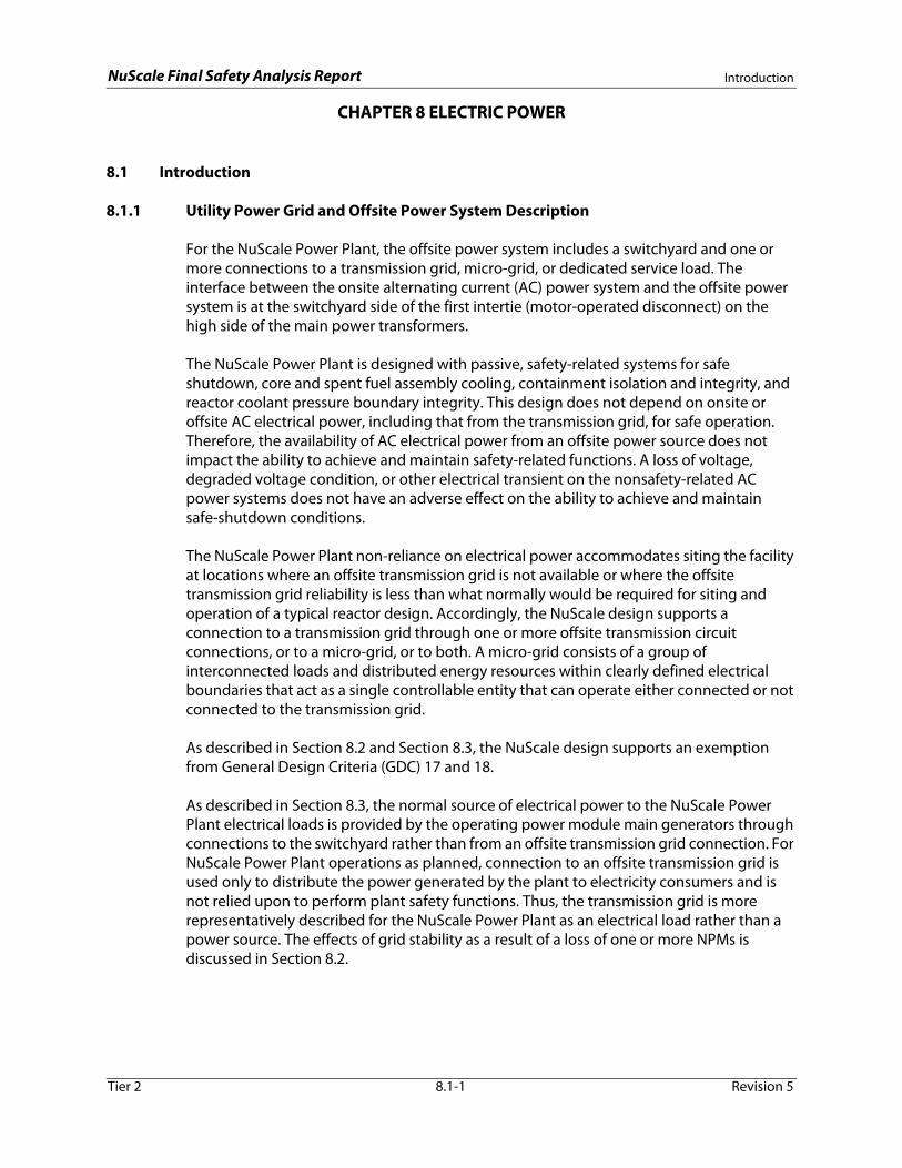
For the NuScale Power Plant, the offsite power system includes a switchyard and one or more connections to a transmission grid, micro-grid, or dedicated service load. The interface between the onsite alternating current (AC) power system and the offsite power system is at the switchyard side of the first intertie (motor-operated disconnect) on the high side of the main power transformers.
The NuScale Power Plant is designed with passive, safety-related systems for safe shutdown, core and spent fuel assembly cooling, containment isolation and integrity, and reactor coolant pressure boundary integrity. This design does not depend on onsite or offsite AC electrical power, including that from the transmission grid, for safe operation. Therefore, the availability of AC electrical power from an offsite power source does not impact the ability to achieve and maintain safety-related functions. A loss of voltage, degraded voltage condition, or other electrical transient on the nonsafety-related AC power systems does not have an adverse effect on the ability to achieve and maintain safe-shutdown conditions.
The NuScale Power Plant non-reliance on electrical power accommodates siting the facility at locations where an offsite transmission grid is not available or where the offsite transmission grid reliability is less than what normally would be required for siting and operation of a typical reactor design. Accordingly, the NuScale design supports a connection to a transmission grid through one or more offsite transmission circuit connections, or to a micro-grid, or to both. A micro-grid consists of a group of interconnected loads and distributed energy resources within clearly defined electrical boundaries that act as a single controllable entity that can operate either connected or not connected to the transmission grid.
As described in Section 8.2 and Section 8.3, the NuScale design supports an exemption from General Design Criteria (GDC) 17 and 18.
As described in Section 8.3, the normal source of electrical power to the NuScale Power Plant electrical loads is provided by the operating power module main generators through connections to the switchyard rather than from an offsite transmission grid connection. For NuScale Power Plant operations as planned, connection to an offsite transmission grid is used only to distribute the power generated by the plant to electricity consumers and is
Tier 2 8.1-1 Revision 5
not relied upon to perform plant safety functions. Thus, the transmission grid is more representatively described for the NuScale Power Plant as an electrical load rather than a power source. The effects of grid stability as a result of a loss of one or more NPMs is discussed in Section 8.2.

NuScale Final Safety Analysis Report Introduction
8.1.2 Onsite Power System Description
The onsite electrical power systems include AC power systems and direct current (DC) power systems. Also included is a backup power supply system (BPSS) consisting of diesel generators and an auxiliary AC power source (AAPS).
8.1.2.1 Onsite Alternating Current Power System
The onsite AC power systems are nonsafety-related, non-Class 1E and include the following:
• Normal AC power system
− 13.8 kV and Switchyard system (EHVS) with nominal bus voltage of 13.8 kV
− Medium voltage AC electrical distribution system (EMVS) with nominal bus voltage of 4.16kV
− Low voltage AC electrical distribution system (ELVS) with nominal bus voltages of 480V and 120V
• BPSS
− Backup diesel generators (BDGs) with nominal output voltage of 480V
− AAPS with nominal output voltage of 13.8kV
Power to the onsite AC power systems is normally provided by the operating NuScale Power Module (NPM) main generators connected to the EHVS (see Figure 8.3-2a and Figure 8.3-2b). Medium-voltage and low-voltage plant auxiliary and service loads are supplied through the unit auxiliary transformers, which also are connected to the EHVS. Power that is generated in excess of plant load requirements is supplied to the switchyard through the main power transformers. Either a transmission grid connection or the AAPS also may provide power to the onsite AC power system through the EHVS during periods when the NPMs are not operating. Whether power is provided from the main generators, a transmission grid, or the AAPS, the power flow to plant loads is from the EHVS main generator buses to the EMVS through the unit auxiliary transformers.
The EHVS voltage is reduced by the unit auxiliary transformers to the EMVS nominal bus voltage of 4.16kV. The EMVS is depicted in Figure 8.3-3a and Figure 8.3-3b. The EMVS buses distribute power to the loads at 4.16kV.
The EMVS voltage is reduced by the station service transformers to the ELVS nominal bus voltage of 480 V from which power is distributed to the 480 V plant loads. The ELVS
Tier 2 8.1-2 Revision 5
is depicted in Figure 8.3-4a through Figure 8.3-4z.
A loss of voltage or degraded voltage condition on the AC power systems does not adversely affect the performance of plant safety-related functions. See Section 8.3 for additional detail.
The BPSS provides backup sources of AC electrical power when the normal AC power sources are not available. This condition would occur if none of the NPMs were

NuScale Final Safety Analysis Report Introduction
operating and a connection to a transmission grid is not provided as part of the site-specific design or is not available. The BPSS power generation sources include two BDGs and an AAPS as described in Section 8.3. Neither the BDGs nor the AAPS is relied upon to achieve and maintain plant safety-related functions. Although BPSS capability is included in the NuScale design, non-reliance on AC power eliminates the need for an alternate AC power source to meet the station blackout (SBO) coping requirements. An evaluation of SBO for the NuScale design is provided in Section 8.4.
The NuScale Power Plant is designed with the capability to operate independently of a connection to an external transmission grid. The “island mode” design feature provides nonsafety and not risk-significant operating flexibility that is not relied upon to satisfy safety-related functions. Island mode capability, combined with the availability of the BPSS power generation sources, reduces the likelihood of a complete loss of AC power.
The BDGs provide backup electrical power to selected equipment loads. The primary BDG load is the highly reliable DC power system (EDSS). The BDG portion of the BPSS and its connections to the ELVS is shown in Figure 8.3-4a through Figure 8.3-4z. The ELVS equipment and circuits downstream of these motor control centers are used to route the power to the selected loads.
The AAPS is capable of providing power to plant auxiliary and service loads during periods when other AC power sources are not available. This capability includes providing electrical power for initial startup of an NPM (i.e., black start), and for normal shutdown and cooldown of NPMs in the unlikely event of a simultaneous loss of the operating main generators and a transmission grid connection (if provided). The AAPS is connected directly to the EHVS 13.8kV generator buses through its generator circuit breaker as shown in Figure 8.3-2a and Figure 8.3-2b.
Refer to Section 8.3.1 for a detailed description of the onsite AC electrical power systems.
8.1.2.2 Onsite Direct Current Power System
The onsite DC power systems are non-Class 1E and nonsafety-related. These systems include the following:
• highly reliable DC power system (EDSS)
• normal DC power system (EDNS)
The EDSS is comprised of two DC subsystems which provide a continuous, failure-tolerant source of 125 Vdc power to assigned plant loads during normal plant
Tier 2 8.1-3 Revision 5
operation and for a specified minimum duty cycle following a loss of AC power. The EDSS is failure tolerant because any piece of EDSS equipment can fail or be removed from service without adversely affecting EDSS functional capability. The EDSS common plant subsystem (EDSS-C) serves the plant common loads which have functions not specific to a single NPM. The EDSS module-specific plant subsystem (EDSS-MS) consists of up to 12 separate and independent DC electrical power supply systems, one for each individual NPM. The EDSS-MS for a NPM provides electrical power for the module protection system and other loads associated with that NPM. Figure 8.3-6, Figure 8.3-7a, and Figure 8.3-7b provide the simplified one line diagrams of the EDSS-C

NuScale Final Safety Analysis Report Introduction
and EDSS-MS designs. As shown in these figures, the source of electrical supply to the EDSS-C and EDSS-MS battery chargers is the ELVS, described in Section 8.3.1.
The EDNS shown in Figure 8.3-8a through Figure 8.3-8f is not required for nuclear safety. The EDNS contains both 250 Vdc and 125 Vdc batteries and is shared between the NPMs. EDNS provides both DC power and AC power (via inverters at 120/208 Vac) to nonsafety-related loads that support functions related to investment protection and power generation. The EDNS battery chargers are supplied from the ELVS.
See Section 8.3.2 for a detailed description of the onsite DC electrical power systems.
8.1.3 Safety-Related Loads
The NuScale design does not include safety-related loads and does not rely on electrical power or operator action to achieve and maintain safe shutdown. The safety-related systems actuate by passive means and their continued operation relies on natural mechanisms based on fundamental physical and thermodynamic principles (e.g., gravity; natural circulation; convective, radiative, and conductive heat transfer; condensation; and evaporation).
In the NuScale design, safety-related functions are assured upon a loss of electrical power to the loads. Safety-related SSC do not require electric power to perform plant safety-related functions during a design basis event.
8.1.4 Design Bases
8.1.4.1 Offsite Power System
The design bases for the offsite power system, if provided, are site-specific and are described in Section 8.2.
8.1.4.2 Onsite Power System
The EDSS is designed as a non-Class 1E system whose functions are nonsafety-related and not risk-significant. Although the EDSS is not safety-related, it is designed as a highly reliable DC power system to support important plant loads, as described in Section 8.3.2. Common cause failures are minimized by the EDSS design. Reliability is provided by designing double redundancy into the batteries and battery chargers for each EDSS channel or division. Independence of the redundant equipment is maintained by applying appropriate physical separation and electrical isolation measures between the non-Class 1E and Class 1E equipment. The EDSS-C sub-system
Tier 2 8.1-4 Revision 5
supplies electrical power to common plant loads, the EDSS-MS subsystems are not designed to be shared between NPMs.
The EDSS battery design provides for 24 or 72 hour duty cycles based upon the required function of the connected loads.
The EDNS is designed as a non-Class 1E system whose functions are nonsafety-related and not risk-significant. The EDNS batteries are designed to provide DC power and AC

NuScale Final Safety Analysis Report Introduction
power (via inverters) after a loss of power to the battery chargers, after which the on-site standby power sources restore AC power to the EDNS battery chargers.
The EHVS is designed as a non-Class 1E system whose functions are nonsafety-related and not risk-significant. The EHVS is designed with the capability for the EHVS buses to be connected, through the switchyard, to any onsite main generator for operation in island mode. The EHVS equipment is physically separated from safety related circuits and is not located near safety-related components.
The EMVS is designed as a non-Class 1E system whose functions are nonsafety-related and not risk-significant. The EMVS circuits are physically separated from safety circuits throughout the plant and EMVS equipment is not located near safety-related components.
The ELVS is designed as a non-Class 1E system whose functions are nonsafety-related and not risk-significant.The ELVS design includes upstream fault protection to the pressurizer heater circuits.
The BPSS is designed to provide electrical power to the NuScale Power Plant when AC power is not available. The BPSS is a non-Class 1E system whose functions are non-safety related and not risk-significant. The AAPS and the BDGs are designed to automatically start on a loss of 13.8 kV bus voltage and to be manually connected to provide backup AC power to the affected loads.
8.1.4.3 Regulatory Requirements and Guidance
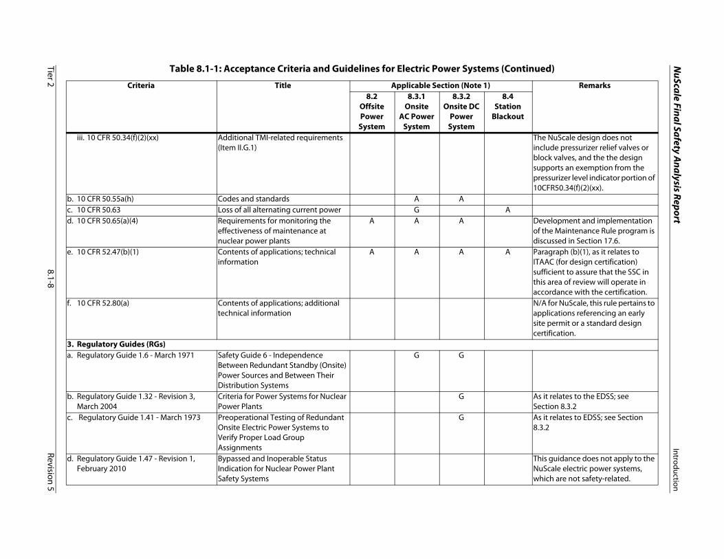
Table 8.1-1 summarizes the extent to which Nuclear Regulatory Commission (NRC) requirements and guidance relevant to electrical systems are applied in the design of NuScale electrical systems. Conformance with NRC requirements and guidance also is summarized in Section 1.9 and Section 3.1. In general, electrical systems are designed in accordance with the requirements and guidance with exceptions or clarifications noted below:
• The design of the NuScale offsite, onsite AC, and onsite DC electrical systems conforms to GDC 2, GDC 4, and GDC 5 to the extent described in Section 8.2, Section 8.3.1, and Section 8.3.2. As described in Section 3.1, the NuScale design supports an exemption from GDC 17, GDC 18, and GDC 33.
• The plant design complies with a set of principal design criteria in lieu of GDC 34, 35, 38, 41, and 44, as described in Section 3.1.4. The principal design criteria do not include requirements for electric power systems.
Tier 2 8.1-5 Revision 5
• The electrical penetration assembly (EPA) design conforms to GDC 50. Section 8.3.1.2.5 addresses the EPA electrical design requirements. Sections 3.8.2 and 6.2.1 address the mechanical integrity requirements of GDC 50.
• The NuScale design does not rely on pressurizer heaters to establish and maintain natural circulation in shutdown conditions. Accordingly, the NuScale design supports an exemption from the 10 CFR 50.34(f)(2)(xiii) (TMI Item II.E.3.1) requirement to provide pressurizer heater power supply and associated motive and control power interfaces to establish and maintain natural circulation in shutdown conditions.

NuScale Final Safety Analysis Report Introduction
• The NuScale design does not include pressurizer relief valves or pressurizer relief block valves. Therefore, 10 CFR 50.34(f)(2)(xx) (TMI Item II.G.1) requirements to provide emergency power sources and qualified motive and control power connections for such valves are not technically relevant to the NuScale design. The NuScale design supports an exemption from the portions of the rule which require vital power buses for pressurizer level indicators.
• The extent to which the design of NuScale electrical systems conforms to 10 CFR 50.55a(h) is described in Section 8.3.1 and Section 8.3.2.
• The NuScale Power Plant design conforms to the requirements of 10 CFR 50.63 for a light water reactor to have the capability to withstand an SBO for a specified duration and recover from an SBO as defined in 10 CFR 50.2. Additional details regarding conformance with 10 CFR 50.63 are described in Section 8.4.
• The 10 CFR 50.65(a)(4) assessment is applied to NuScale electrical system SSC that (1) are determined to meet the 10 CFR 50.65(b) criteria, and (2) a risk-informed evaluation process has shown to be significant to public health and safety. Section 17.6 describes the maintenance rule (10 CFR 50.65) program.
• NUREG-0737 includes guidance related to TMI Item II.E.3.1 (codified in 10 CFR 50.34(f)(2)(xiii)), and TMI Item II.G.1 (codified in 10 CFR 50.34(f)(2)(xx)). As described above for 10 CFR 50.34(f)(2), the NuScale design supports exemptions from these regulations.
• Portions of NUREG/CR-0660 relevant to the NuScale electrical systems are considered as reference only, consistent with NuScale DSRS Section 8.1. Conformance with TMI items, including those addressed in this NUREG, is described in Section 1.9.
• SECY-90-016 pertains to evolutionary advanced light water reactor (ALWR) designs and is not directly applicable to passive plant designs. As a passive ALWR design, the NuScale electrical system design conforms to the passive plant guidance of SECY-94-084, Section F.
• SECY-91-078 pertains to evolutionary ALWR designs and is not directly applicable to passive plant designs. As a passive ALWR design, the NuScale electrical system design conforms to the passive plant guidance of SECY-94-084, Section G.
• The design of NuScale electrical systems conforms to the Commission-approved positions in Sections F and G of SECY-94-084 related to passive plant electrical systems.
• The evaluation of NuScale electrical systems under the regulatory treatment of nonsafety systems (RTNSS) process conforms to SECY-94-084, Section A, as modified in SECY-95-132 and subsequently established in NUREG-0800, Section
Tier 2 8.1-6 Revision 5
19.3. The portion of SECY-95-132 that modifies the RTNSS process description in SECY-94-084, Section A, is applied as guidance to the NuScale nonsafety-related electrical systems. Specifically, the evaluation of NuScale electrical systems under the RTNSS process conforms to Attachment1 (Item A) of SECY-95-132.

NuScale Final Safety A
nalysis ReportIntroduction
Tier 28.1-7
Revision 5
Table 8.1-1: Acceptance Criteria and Guidelines for Electric Power Systems
Criteria Title Applicable Section (Note 1) Remarks8.2
OffsitePower
System
8.3.1Onsite
AC PowerSystem
8.3.2Onsite DC
PowerSystem
8.4Station
Blackout
1. 10 CFR 50, Appendix A, General Design Criteria for Nuclear Plantsa. GDC 2 Design bases for protection against
natural phenomenaA A §8.2 - ADAMS Accession
No. ML090260039 b. GDC 4 Environmental and dynamic effects
design basesA A §8.2 - ADAMS Accession
No. ML090260039c. GDC 5 Sharing of structures, systems, and
componentsA A §8.2 - ADAMS Accession
Nos. ML11133A334 and ML090260039
d. GDC 17 Electric power systems The NuScale design supports an exemption from GDC 17.
e. GDC 18 Inspection and testing of electric power systems
The NuScale design supports an exemption from GDC 18.
f. GDC 33 Reactor coolant makeup The NuScale design supports an exemption from GDC 33.
g. GDCs 34, 35, 38, 41, 44 Residual heat removal, emergency core cooling, containment heat removal, containment atmosphere cleanup, cooling water
The plant design complies with a set of principal design in lieu of these GDC, as described in Section 3.1.4.
h. GDC 50 Containment design basis A A The electrical design requirements for electrical penetration assemblies are included in Section 8.3.1.
2. Regulations (10 CFR 50 and 10 CFR 52)a. 10 CFR 50.34 Contents of applications; technical
informationi. 10 CFR 50.34(f)(2)(v) Additional Three Mile Island
(TMI)-related requirements (Item I.D.3)
This requirement is not applicable to the NuScale electric power systems, which are not safety-related.
ii. 10 CFR 50.34(f)(2)(xiii) Additional TMI-related requirements (Item II.E.3.1)
The NuScale design supports an exemption from 10CFR50.34(f)(2)(xiii).
NuScale Final Safety A
nalysis ReportIntroduction
Tier 28.1-8
Revision 5
iii. 10 CFR 50.34(f)(2)(xx) Additional TMI-related requirements (Item II.G.1)
The NuScale design does not include pressurizer relief valves or block valves, and the the design supports an exemption from the pressurizer level indicator portion of 10CFR50.34(f)(2)(xx).
b. 10 CFR 50.55a(h) Codes and standards A Ac. 10 CFR 50.63 Loss of all alternating current power G Ad. 10 CFR 50.65(a)(4) Requirements for monitoring the
effectiveness of maintenance at nuclear power plants
A A A Development and implementation of the Maintenance Rule program is discussed in Section 17.6.
e. 10 CFR 52.47(b)(1) Contents of applications; technical information
A A A A Paragraph (b)(1), as it relates to ITAAC (for design certification) sufficient to assure that the SSC in this area of review will operate in accordance with the certification.
f. 10 CFR 52.80(a) Contents of applications; additional technical information
N/A for NuScale, this rule pertains to applications referencing an early site permit or a standard design certification.
3. Regulatory Guides (RGs)a. Regulatory Guide 1.6 - March 1971 Safety Guide 6 - Independence
Between Redundant Standby (Onsite) Power Sources and Between Their Distribution Systems
G G
b. Regulatory Guide 1.32 - Revision 3, March 2004
Criteria for Power Systems for Nuclear Power Plants
G As it relates to the EDSS; see Section 8.3.2
c. Regulatory Guide 1.41 - March 1973 Preoperational Testing of Redundant Onsite Electric Power Systems to Verify Proper Load Group Assignments
G As it relates to EDSS; see Section 8.3.2
d. Regulatory Guide 1.47 - Revision 1, February 2010
Bypassed and Inoperable Status Indication for Nuclear Power Plant Safety Systems
This guidance does not apply to the NuScale electric power systems, which are not safety-related.
Table 8.1-1: Acceptance Criteria and Guidelines for Electric Power Systems (Continued)
Criteria Title Applicable Section (Note 1) Remarks8.2
OffsitePower
System
8.3.1Onsite
AC PowerSystem
8.3.2Onsite DC
PowerSystem
8.4Station
Blackout

NuScale Final Safety A
nalysis ReportIntroduction
Tier 28.1-9
Revision 5
e. Regulatory Guide 1.53 - Revision 2, November 2003
Application of the Single-Failure Criterion to Safety Systems
G G As it relates to the EDSS; see Section 8.3.2
f. Regulatory Guide 1.63 - Revision 3, February 1987
Electric Penetration Assemblies in Containment Structures for Nuclear Power Plants
G G The electrical design requirements for electrical penetration assemblies (EPAs) with respect to RG 1.63 are included in Section 8.3.
g. Regulatory Guide 1.68 - Revision 4, June 2013
Initial Test Programs for water-CooledNuclear Power Plants
G G G As it relates to the EDSS; see Section 8.3.2. See Section 8.2 as it relates to the offsite power system.
h. Regulatory Guide 1.75 - Revision 3, February 2005
Criteria for Independence of Electrical Safety Systems
G G As it relates to the EDSS; see Section 8.3.2
i. Regulatory Guide 1.81 - Revision 1, January 1975
Shared Emergency and Shutdown Electric Systems for Multi-Unit Nuclear Power Plants
G G EDSS-MS is not shared; sharing of EDSS-C meets the intent of the guidance; see Section 8.3.2
j. Regulatory Guide 1.106 - Revision 2, February 2012
Thermal Overload Protection for Electric Motors on Motor-Operated Valves
Not applicable; the design does not include safety-related MOVs
k. Regulatory Guide 1.118 - Revision 3, April 1995
Periodic Testing of Electric Power and Protection Systems
G G As it relates to the EDSS; see Section 8.3.2
l. Regulatory Guide 1.128 Revision 2, February 2007
Installation Design and Installation of Vented Lead-Acid Storage Batteries for Nuclear Power Plants
G Applicability as described in Reference 8.3-1 and Section 8.3.2
m. Regulatory Guide 1.129 - Revision 3, September 2013
Maintenance, Testing, and Replacement of Vented Lead-Acid Storage Batteries for Nuclear Power Plants
G Applicability as described in Reference 8.3-1 and Section 8.3.2
n. Regulatory Guide 1.153 - Revision 1, June 1996
Criteria for Safety Systems G G §8.3.2 - Applies to EDSS to the extent described in Reference 8.3-1
o. Regulatory Guide 1.155 - August 1988 Station Blackout G G G Limited to portions relevant to passive plant designs; see Section 8.4
p. Regulatory Guide 1.160 - Revision 3, May 2012
Monitoring the Effectiveness of Maintenance at Nuclear Power Plants
G G
Table 8.1-1: Acceptance Criteria and Guidelines for Electric Power Systems (Continued)
Criteria Title Applicable Section (Note 1) Remarks8.2
OffsitePower
System
8.3.1Onsite
AC PowerSystem
8.3.2Onsite DC
PowerSystem
8.4Station
Blackout

NuScale Final Safety A
nalysis ReportIntroduction
Tier 28.1-10
Revision 5
q. Regulatory Guide 1.204 - November 2005
Guidelines for Lightning Protection of Nuclear Power Plants
G
r. Regulatory Guide 1.206 - June 2007 Combined License Applications for Nuclear Power Plants (LWR Edition)
G G G G
s. Regulatory Guide 1.212 - November 2008
Sizing of Large Lead-Acid Storage Batteries
G As it relates to sizing VRLA batteries; see Section 8.3.2
t. Regulatory Guide 1.218 - April 2012 Condition-Monitoring Techniques for Electric Cables Used in Nuclear Power Plants
G G G Limited to cables determined to be within the scope of 10 CFR 50.65
4. Branch Technical Positions (BTPs)a. SRP BTP 8-1 Requirements on Motor-Operated
Valves in the ECCS Accumulator LinesNot applicable; the design does not include safety-related MOVs or ECCS accumulator lines
b. SRP BTP 8-2 Use of Onsite AC Power Sources for Peaking
G As it relates to the non-Class 1E BDGs; see Section 8.3.1
c. SRP BTP 8-3 Stability of Offsite Power Systems Gd. SRP BTP 8-4 Application of the Single Failure
Criterion to Manually-Controlled Electrically-Operated Valves
Not applicable; see Section 8.3.1 and Section 8.3.2
e. SRP BTP 8-5 Supplemental Guidance for Bypass and Inoperable Status Indication for Engineered Safety Features Systems
This BTP does not apply to NuScale electric power systems as these systems are not engineered safety features and are not relied on to support engineered safety features.
f. SRP BTP 8-6 Adequacy of Station Electric Distribution System Voltages
Not applicable; See Section 8.2.3 and Section 8.3.1
g. SRP BTP 8-7 Criteria for Alarms and Indications Associated with Diesel-Generator Unit Bypassed and Inoperable Status
Not applicable; no Class 1E emergency diesel generators
h. SRP BTP 8-8 Onsite (emergency diesel generators) and offsite power sources allowed outage time extensions
Not applicable; with non-reliance on AC power, no technical specification operating restrictions for inoperable AC power sources
Table 8.1-1: Acceptance Criteria and Guidelines for Electric Power Systems (Continued)
Criteria Title Applicable Section (Note 1) Remarks8.2
OffsitePower
System
8.3.1Onsite
AC PowerSystem
8.3.2Onsite DC
PowerSystem
8.4Station
Blackout

NuScale Final Safety A
nalysis ReportIntroduction
Tier 28.1-11
Revision 5
i. SRP BTP 8-9 Open Phase Conditions in Electric Power System
G G See Section 8.2
5. NUREG Reportsa. NUREG-0737 Clarification of TMI Action Plan
RequirementsSee Section 8.1.4.3
b. NUREG/CR-0660 Enhancement of Onsite Diesel Generator Reliability
G Reference only
6. Commission Papers (SECYs)a. SECY-90-016 Evolutionary Light Water Reactor
Certification Issues and their Relationships toCurrent Regulatory Requirements, 1990
Not applicable
b. SECY-91-078 Electric Power Research Institute Requirements Document and Additional Evolutionary Light Water Reactor (LWR) Certification Issues, 1991
Not applicable
c. SECY-94-084 Policy and Technical Issues Associated with the RTNSS in Passive Plant Designs, 1994
G G G G Used as guidance as described in Section 8.1.4.3
d. SECY-95-132 Policy and Technical Issues Associated with the RTNSS in Passive Plant Designs, 1995
G G G G Used as guidance as described in Section 8.1.4.3
7. NRC Bulletinsa. NRC Bulletin 2012-01 (July 2012) Design Vulnerability in Electric
Power SystemG G See Section 8.2.
1. "A" denotes acceptance criteria, and "G" denotes guidance, applied in the design of NuScale electrical systems. No letter denotes "Not Applicable."
Table 8.1-1: Acceptance Criteria and Guidelines for Electric Power Systems (Continued)
Criteria Title Applicable Section (Note 1) Remarks8.2
OffsitePower
System
8.3.1Onsite
AC PowerSystem
8.3.2Onsite DC
PowerSystem
8.4Station
Blackout

NuScale Final Safety Analysis Report Offsite Power System
8.2 Offsite Power System
8.2.1 Description
For the NuScale Power Plant, the offsite power system includes the switchyard and one or more connections to a transmission grid, micro-grid, or dedicated service load. The interface between the onsite alternating current (AC) power system and the offsite power system is at the switchyard side of the first intertie (motor-operated disconnect) on the high side of the main power transformers (MPTs). The MPTs are included in the 13.8 kV and switchyard electrical system (EHVS), which is described in Section 8.3.1.
The passive design of the NuScale Power Plant does not rely on AC power and does not require an offsite power system to mitigate design basis events as described in Section 15.0.0 or to perform risk-significant functions. Accordingly, the NuScale design supports an exemption from GDC 17 and GDC 18. While this section provides the regulatory framework and a description of an offsite power system, the design of the switchyard and the connections to an offsite power system (if provided) are site-specific considerations.
During normal operations with at least one NuScale Power Module operating, the associated turbine generator is the source of power to the onsite AC power system as described in Section 8.3.1. A single turbine generator has sufficient capacity to meet the maximum expected total auxiliary AC load requirements for up to 12 NuScale Power Modules such that excess power is supplied to the offsite power system if one or more turbine generators are operating.
The onsite auxiliary AC power source may be used as the power source for the AC power system during startup if the NuScale Power Modules are not operating. Offsite power is a secondary source for plant startup or shutdown. If the auxiliary AC power source or a turbine generator is not available, the NuScale Power Plant is designed to backfeed power through the MPTs from an offsite power source for startup or shutdown loads. The NuScale Power Plant has the capability to operate independently from the offsite power system in island mode as discussed in Section 8.3.1.
8.2.2 Switchyard
The design of the switchyard and the connections to an offsite power system are site-specific and are the responsibility of the combined license (COL) applicant.
COL Item 8.2-1: A COL applicant that references the NuScale Power Plant design certification will describe the site-specific switchyard layout and design, including offsite power
Tier 2 8.2-1 Revision 5
connections, control and indication, characteristics of circuit breakers and buses, protective relaying, power supplies, lightning and grounding protection equipment, and conformance with General Design Criteria (GDC) 5.
NuScale Final Safety Analysis Report Offsite Power System
8.2.3 Analysis
8.2.3.1 Analysis of Grid Stability
COL Item 8.2-2: A COL applicant that references the NuScale Power Plant design certification will describe the site-specific offsite power connection and grid stability studies, including the effects of grid contingencies such as the loss of the largest operating unit on the grid, the loss of one NuScale Power Module, and the loss of the full complement of NuScale Power Modules (up to 12). The study will be performed in accordance with the applicable Federal Energy Regulatory Commission, North American Electric Reliability Corporation, and transmission system operator requirements, including communication agreements and protocols.
8.2.3.2 Analysis of Offsite Power System Conformance with Regulatory Framework
This section describes the extent to which the design of the offsite power system conforms to NRC requirements and guidance.
General Design Criteria 17
The NuScale design supports an exemption from the GDC 17 requirements for an offsite power system. The passive design of the NuScale Power Plant does not rely on onsite AC power and does not require an offsite power system to assure that specified acceptable fuel design limits and design conditions of the reactor coolant pressure boundary are not exceeded as a result of anticipated operational occurrences or to maintain core cooling or containment integrity in the event of postulated accidents, as discussed in Section 15.0.0. In addition, the offsite power system is not relied upon to provide power for risk-significant functions.
General Design Criteria 18
As described above, the NuScale design supports an exemption from GDC 17. Accordingly, the design supports an exemption from the GDC 18 inspection and testing requirements.
General Design Criteria 33
The NuScale design supports an exemption from GDC 33, as described in Section 3.1.4.
General Design Criteria 34, 35, 38, 41, and 44
Tier 2 8.2-2 Revision 5
The plant design complies with a set of principal design criteria in lieu of these GDC, as described in Section 3.1.4. The principal design criteria do not include requirements for electric power systems.
10 CFR 50.63
The NuScale Power Plant conformance with 10 CFR 50.63 is described in Section 8.4.

NuScale Final Safety Analysis Report Offsite Power System
10 CFR 50.65(a)(4)
The development and implementation of the maintenance rule (10 CFR 50.65) program, including the identification of structures, systems, and components that require assessment in accordance with 10 CFR 50.65(a)(4), is described in Section 17.6.
Regulatory Guide 1.218 (April 2012)
Regulatory Guide 1.218 provides guidance for monitoring the condition of cables that have been determined to fall within the scope of the maintenance rule (10 CFR 50.65). The development and implementation of the maintenance rule program, including the identification of SSC that require assessment per 10 CFR 50.65(a)(4), is stated in Section 17.6.
Branch Technical Position 8-3 Revision 3
The performance of grid stability studies is site-specific and is addressed in Section 8.2.3.1.
Branch Technical Position 8-6 Revision 3
Branch Technical Position (BTP) 8-6 addresses the adequacy of offsite system voltages to Class 1E (safety-related) loads. The offsite power system does not supply power to Class 1E loads and does not support safety-related functions. Accordingly, BTP 8-6 is not applicable to the offsite power system.
Branch Technical Position 8-9 Revision 0
The BTP 8-9 addresses the effects of transmission grid open-phase conditions as identified in NRC Information Notice 2012-03 and NRC Bulletin 2012-01. This guidance involves protection from a common cause AC power failure due to open phase conditions in the offsite power sources that are credited for GDC 17 and the effect on onsite safety-related buses and safety-related loads. The offsite power system does not support safety-related functions. In addition, failures of the offsite power system, including open phase conditions or a station blackout, do not prevent the operation of safety-related functions.
If the offsite power system is supplying power to the onsite AC power system, the electrical isolation between the highly reliable DC power system and equipment with safety-related functions, which is described in Section 7.1.2, ensures that the open phase conditions described in BTP 8-9 would not prevent the performance of
Tier 2 8.2-3 Revision 5
safety-related functions.
Regulatory Guide 1.32 Revision 3
Regulatory Guide 1.32 addresses design criteria for safety-related power systems. The NuScale Power Plant does not rely on an offsite power system to support or perform safety functions. Accordingly, Regulatory Guide 1.32 is not applicable to the offsite power system.
NuScale Final Safety Analysis Report Offsite Power System
Regulatory Guide 1.68 Revision 4
COL Item 8.2-3: A COL applicant that references the NuScale Power Plant design certification will describe the testing of the switchyard and the connections to an offsite power system, if provided, consistent with Regulatory Guide 1.68, Revision 4. The testing description will include the details of initial testing associated with degraded offsite power conditions.
SECY 94-084 and SECY 95-132
FSAR Section 17.4.3 describes the NuScale methodology to establish risk significance of SSC. The NuScale process for evaluating SSC against the RTNSS criteria is described in FSAR Section 19.3. This process did not identify safety-related or risk-significant loads for the offsite power system.
The lack of safety-related and risk-significant AC loads and the 72-hour SBO coping capability of the passive NuScale design as described in Section 8.4 obviate the need for an alternate AC power source or a safety-related emergency diesel generator, consistent with SECY 94-084 Parts F and G which were confirmed in SECY 95-132.
Tier 2 8.2-4 Revision 5

NuScale Final Safety Analysis Report Onsite Power Systems
8.3 Onsite Power Systems
The onsite power systems provide power to the plant loads during all modes of plant operation. The onsite power systems include alternating current (AC) power systems and direct current (DC) power systems. The plant safety-related functions are achieved and maintained without reliance on electrical power; therefore, neither the AC power systems nor the DC power systems are required to be safety-related (Class1E). This conclusion is confirmed by the application of the evaluation methodology described in NuScale topical report TR-0815-16497-P-A (Reference 8.3-1). Table 8.3-9 provides a cross reference of the FSAR sections that demonstrate compliance with the conditions of applicability and the additional limitations in the NRC Safety Evaluation Report (SER) associated with this topical report.
The nonsafety-related onsite AC power systems are described in Section 8.3.1. The nonsafety-related DC power systems are described in Section 8.3.2. Structures, systems, and components (SSC) classification information for the onsite power systems is provided in Section 3.2.
8.3.1 Alternating Current Power Systems
8.3.1.1 System Description
The onsite AC power systems distribute AC power to the onsite DC power systems (through battery chargers) and to the plant AC electrical loads during startup and shutdown, normal operation, and off-normal conditions. The NuScale Power Plant does not use nor include an emergency onsite AC power system. The onsite AC power systems are shared between the NuScale Power Modules (NPMs), and include the following:
• normal power system (Section 8.3.1.1.1)
− 13.8 kV and switchyard system (EHVS) with nominal bus voltage of 13.8 kV
− medium voltage AC electrical distribution system (EMVS) with nominal bus voltage of 4.16 kV
− low voltage AC electrical distribution system (ELVS) with nominal bus voltages of 480 V and 120 V
• backup power supply system (BPSS) (Section 8.3.1.1.2)
− backup diesel generators (BDGs) with nominal output voltage of 480 V
− auxiliary AC power source (AAPS) with nominal output voltage of 13.8 kV
The normal source of onsite AC electrical power is from the operating NPM turbine
Tier 2 8.3-1 Revision 5
generators (see Figure 8.3-2a and Figure 8.3-2b) through the EHVS generator buses. The EHVS supplies the plant loads through the unit auxiliary transformers (UATs). The EHVS also supplies the switchyard through the main power transformers (MPTs), which are connected to the offsite transmission grid, a micro-grid (if the plant is not connected to a transmission grid), or both, as described in Section 8.2. Each NPM is designed to sustain a loss of external electrical load from full power while its associated turbine generator remains connected and capable of supplying plant electrical loads. The loss of electrical load capability is not a safety-related function. If the NPMs are not

NuScale Final Safety Analysis Report Onsite Power Systems
operating, the transmission grid connection (if provided) or the AAPS are capable of providing power to the onsite AC power system through the EHVS. The offsite power system is described in Section 8.2.
The UATs reduce the EHVS voltage from 13.8 kV to the EMVS nominal bus voltage of 4.16 kV. The EMVS is depicted in Figure 8.3-3a and Figure 8.3-3b. The power at the EMVS buses is distributed to large (nonsafety-related) pump motor loads and to the high-side terminals of the station service transformers (SSTs). The SSTs are the interface between the EMVS and the ELVS as shown in Figure 8.3-4a through Figure 8.3-4z. The ELVS station service transformers reduce the voltage from 4.16 kV to the ELVS nominal bus voltage of 480 V, which is distributed by the ELVS to the:
• highly reliable DC power system (EDSS) from BDG-backed motor control centers (MCCs) and circuits.
• normal DC power system (EDNS).
• AC equipment loads through MCCs, power panels, and 480 V/120 V transformers.
• other plant static loads, including the plant lighting system (PLS).
The onsite AC power systems do not support plant safety-related functions. The EHVS, EMVS, and ELVS are described in Section 8.3.1.1.1. The design configuration of the EHVS and its interfaces are depicted in Figure 8.3-2a and Figure 8.3-2b. The design configuration of the EMVS, and its interfaces with plant loads and the ELVS are depicted in Figure 8.3-3a and Figure 8.3-3b. The design configuration of the ELVS and its interfaces with ELVS loads are depicted in Figure 8.3-4a through Figure 8.3-4z. The ratings of major AC power system equipment are listed in Table 8.3-1.
The BPSS provides backup sources of AC electrical power to the NuScale Power Plant when the normal AC power sources are not available. This condition would occur only if none of the NPMs are operating and a connection to a transmission grid is not available either because it is not provided as part of the site-specific design, or if provided, is lost. The BPSS power generation sources include two BDGs and an AAPS. The BPSS, including its power generation sources, is described in Section 8.3.1.1.2. The AAPS connections to the EHVS 13.8 kV buses are shown in Figure 8.3-2a and Figure 8.3-2b. The design configuration of the BDG portion of the BPSS and its interfaces with the ELVS are depicted in Figure 8.3-5a and Figure 8.3-5b.
The layout of the onsite AC power system equipment located external to the Turbine Generator Buildings (TGBs) and Reactor Building (RXB) is depicted in Figure 1.2-4. Equipment location and layout allow access for inspection, operability testing, maintenance, and replacement (if required). Adequate working clearance and means
Tier 2 8.3-2 Revision 5
of egress is provided in accordance with National Fire Protection Association 70 (Reference 8.3-3).
Power from the UATs is supplied by cable bus to the EMVS power distribution centers (PDCs). The UATs are located in the plant yard near the TGB and in close proximity to the EHVS. The EMVS 4.16 kV PDCs and switchgear are located in close proximity to the UATs as shown in Figure 1.2-4.
NuScale Final Safety Analysis Report Onsite Power Systems
The SSTs, 480 V load centers, and 480 V MCCs are located strategically to effectively distribute power to electrical loads. The MCCs are located in the RXB, Control Building (CRB), TGBs, Radioactive Waste Building (RWB), and in pre-fabricated PDCs near the loads they serve. The SSTs are located in PDCs near the MCCs and large motors or static loads they serve.
8.3.1.1.1 Normal Power Distribution Systems
Onsite AC electrical power is normally distributed by the EHVS, the EMVS, and the ELVS. These power distribution systems are described in the following subsections.
13.8kV and Switchyard System
The nonsafety-related EHVS provides electrical connections from the turbine generators, the switchyard, and the AAPS to the onsite AC power electrical distribution system and to the offsite power system.
The design configuration of the EHVS and its interfaces with the onsite AC power distribution system are depicted in Figure 8.3-2a and Figure 8.3-2b. The EHVS includes the first intertie (motor-operated disconnect switch) on the high side of the MPTs, the MPT supply breakers, and the 13.8 kV switchgear, breakers, and buses. The EHVS terminates at the high-side terminals of the UATs, which is the interface between the EHVS and the EMVS.
During normal plant operation, each turbine generator (up to 12 per plant site) supplies power to the 13.8 kV generator buses (see Figure 8.3-2a and Figure 8.3-2b) through its own dedicated generator circuit breaker. The offsite power system is connected to the generator buses through the switchyard, MPTs, and grid breakers. The onsite AC power distribution system is connected to the generator buses through the UATs. The power generated by the turbine generators is provided to the plant electrical loads through the UATs and to the offsite power system through the MPTs. Therefore, with at least one NPM operating and generating electrical power, the operating turbine generator provides power to the plant and other connected loads. The ratings of the main generators, generator circuit breakers, and the MPTs are provided in Table 8.3-1. The EHVS circuit breakers are rated and constructed to meet the requirements of IEEE Standard C37.06 (Reference 8.3-23). The EHVS generator circuit breakers are rated and constructed to meet the required capabilities of Institute of Electrical and Electronics Engineers (IEEE) Standard C37.013 (Reference 8.3-24). If the NPMs are not operating, power to the plant loads is supplied from either the offsite power system or the BPSS.
Tier 2 8.3-3 Revision 5
The EDNS provides control power to the 13.8 kV EHVS. See Section 8.3.2 for information related to the EDNS.
As depicted in Figure 8.3-2a and Figure 8.3-2b, up to eight MPTs, and associated generator buses are provided for the NuScale Power Plant. The generator buses and their associated MPTs are equally divided between the north and south TGBs with up to four generator buses and their associated MPTs serving each TGB. The MPTs are three-phase transformers designed for outdoor use. Each MPT and its
NuScale Final Safety Analysis Report Onsite Power Systems
associated switchgear and cabling are sized for the full output of two turbine generators.
The design of the MPTs and associated cabling and switchgear allows one or more main generators, an MPT, a generator bus, or a switchgear to be removed from service for maintenance or refueling without loss of electrical power to the external loads or plant loads. This configuration also allows electrical power to be supplied to plant loads from a single turbine generator with the other turbine generators out of service.
Island mode is a capability that allows operation of the NPMs without a connection to a transmission grid that could provide an offsite AC power supply. In island mode, the plant turbine generators independently provide power to onsite AC loads. Island mode is a nonsafety and non-risk significant design feature that is not credited to meet regulatory or safety-related criteria.
For a NuScale Power Plant that is connected only to a micro-grid or a dedicated service load, island mode represents a normal operating condition with one or more turbine generators providing power to the onsite and offsite AC loads. For a NuScale Power Plant that is normally connected to an offsite power supply via a transmission grid, island mode represents a temporary operating condition until the grid operability is restored.
For the plants with a transmission grid connection, island mode also includes an automatic control function to transition to island mode and maintain power to onsite AC loads in the event the grid is lost or becomes unstable. This automatic function separates the plant from the grid, maintains the operating reactors critical, and maintains uninterrupted power to the onsite AC loads. The service unit is a pre-selected unit (a single NPM and turbine generator combination) that provides power to the plant house loads and sets the AC system frequency and voltage upon automatic transfer to island mode. All units in the plant have the capability to be designated as the service unit.
Given a signal that the grid is lost or unstable, the basic response of the island mode control logic is as follows.
• The switchyard breakers that connect the grid to the plant buses are tripped.
• The service unit generator is switched from droop to isochronous control.
• The turbines and generator breakers for the operating non-service units are tripped and steam is diverted to the associated condensers via the bypass.
Tier 2 8.3-4 Revision 5
• The AAPS is automatically started and may be manually placed in parallel for load following with the service unit in accordance with operating procedures.
After island mode is established and the plant is stable, the operators may choose to reduce power or shutdown units depending on grid and unit conditions. Although the island mode control function is not credited in the safety design basis, it enhances safety by reducing challenges to the safety systems that would respond to an unmitigated grid disturbance, which includes safety systems actuations that result in a reactor trip.

NuScale Final Safety Analysis Report Onsite Power Systems
Medium Voltage Alternating Current Electrical Distribution System
The EMVS is classified as nonsafety-related and its primary function is to supply 4.16 kV power to plant loads during normal power module operations, including NPM startup and shutdown. Each EMVS bus is supplied by a UAT connected to an EHVS bus. Each EMVS bus supplies two ELVS load centers. The loads provided by the EMVS include the ELVS station service transformers and the pump motors for the circulating water system, the site cooling water system, and the chilled water system (CHWS). The EMVS does not provide power to safety-related systems or components.
The EMVS includes UATs, 4.16 kV PDCs, power and control cables, associated raceways, and auxiliaries, such as instrumentation and controls (I&C) and protective relays. These components are described in Section 8.3.1.2.1, Section 8.3.1.2.2, and Section 8.3.1.4. Each UAT is a three-phase, oil-insulated transformer with a single set of secondary windings. The UATs are designed for outdoor mounting and are located in the transformer areas as shown on Figure 1.2-4. As shown in Figure 8.3-3a and Figure 8.3-3b, the primary side of each UAT is connected to its respective EHVS 13.8 kV main generator bus. The 4.16 kV secondary side of each UAT is connected by cable bus to its respective EMVS switchgear. Table 8.3-1 provides the design ratings of the UATs and switchgear. The EMVS switchgear locations are shown in Figure 1.2-4. The loss of an EMVS bus can be mitigated by operating loads on another EMVS bus. The EMVS permanent plant nonsafety loads can be supplied during extended unavailability of the normal power supply, e.g. plant outages, by the BPSS through the EHVS. The BPSS (auxiliary AC power source) interface circuit has sufficient capacity to supply power to maintain shutdown.
Four UATs are provided for the six main generators in the north TGB (which are connected to NPMs 1 through 6), and the remaining four UATs serve the six main generators in the south TGB (which are connected to NPMs 7 through 12). Operational flexibility is provided by the capability to cross-connect the EMVS buses on the north and south sides. The loss of a UAT or [[ voltage regulating transformer (VRT) ]] is mitigated by automatically transferring the affected EMVS bus to an adjacent EMVS bus. The design of the EMVS is such that two UATs can supply the load requirements for six NPMs because each UAT has the capacity and capability to supply 50 percent of the power needed for this configuration under conditions of maximum expected concurrent loads.
Each EMVS bus has tie breakers to adjacent buses. Combined with the UAT capacity, one or two UATs on each side can be removed from service for maintenance without loss of electrical power supply capability to external or plant
Tier 2 8.3-5 Revision 5
loads. The EMVS is designed to automatically transfer the connected EMVS bus to another EMVS bus for a UAT lockout relay operation or bus undervoltage condition.
The UATs are provided with tap changers to provide voltage regulation and to maintain secondary voltage within the established voltage limits. The voltage limits are derived from the EMVS load requirements for the expected range of voltage variations on the EHVS, and for the anticipated transformer loading conditions up to the maximum transformer rating.

NuScale Final Safety Analysis Report Onsite Power Systems
Low Voltage Alternating Current Electrical Distribution System
The nonsafety-related ELVS consists of the onsite electric power distribution circuits that operate at 600 Vac or less, supplying power to low-voltage loads. The ELVS does not include the distribution systems for the plant lighting system (PLS) or the AC power that is provided by inverters in the nonsafety-related EDNS. However, the ELVS supplies power to the Class 1E module protection system (MPS) inline breakers for the pressurizer heaters. These breakers are included in the scope of the MPS discussed in Section 7.1. The distribution systems for the PLS and EDNS, including the AC power inverted by the EDNS, are described in Sections 9.5.3 and Section 8.3.2.1, respectively.
Figure 8.3-4a through Figure 8.3-4z depict the ELVS design configuration for a 12-NPM plant. The ELVS begins at the high-side terminals of the SSTs and ends at the input terminals of the EDSS and EDNS battery chargers; the input terminals of equipment loads, including motors and packaged equipment; and the primary side of lighting transformers. The ELVS includes the SSTs, 480 V load centers, MCCs, distribution transformers, and distribution panels or switchboards. The ELVS also includes power and control cables and associated raceways, and auxiliaries such as I&C and protective relays. These components are described in Section 8.3.1.2.1, Section 8.3.1.2.2, and Section 8.3.1.4. Table 8.3-1 provides the design ratings of the major ELVS components. The layout of the ELVS power distribution centers in the yard area is shown on Figure 1.2-4, with the remainder of the ELVS equipment being located inside the plant buildings.
As shown in Figure 8.3-4a through Figure 8.3-4z, the ELVS is divided into two divisions, nonsafety-related Division 1 and nonsafety-related Division 2. Each division supplies power to its connected nonsafety-related loads. Electrical power to each SST is provided from the EMVS. To maximize plant availability and operational flexibility, the ELVS is designed so that failure or unavailability of a single SST does not adversely affect NPM operation.
Each NPM is supplied by two double-ended ELVS main-tie-main load centers that have an SST connected to each load center bus through a main breaker. One of the load centers consists of two buses of nonsafety-related Division 1 power and the other load center consists of two buses of nonsafety-related Division 2 power. Each SST and its EMVS power supply feed has the capacity to provide power to both load center buses. Therefore, if the SST for a load center bus fails or is unavailable, continuous system operation is maintained by automatic transfer of the affected bus to the remaining bus by the tie breaker between the two load center buses. Electrical interlocks are provided to prevent parallel operation of redundant
Tier 2 8.3-6 Revision 5
sources feeding the ELVS buses.
8.3.1.1.2 Backup Power Supply System
The principal function of the nonsafety-related BPSS is to provide electrical power to the NuScale Power Plant when the normal AC power is not available. Safety-related functions do not rely on AC electrical power from the BPSS. The BPSS includes two redundant BDGs and an AAPS, as well as electrical equipment and circuits used to interconnect the BDGs to the ELVS and the AAPS to the EHVS.

NuScale Final Safety Analysis Report Onsite Power Systems
In the event of a complete loss of voltage on the 13.8 kV main generator buses, the BDGs and the AAPS are automatically started after a 30-second time delay. The time delay after the loss of voltage signal eliminates transient or false alarms. The BPSS equipment status and indication are available both locally and in the main control room (MCR). The operator has the capability to manually start the BDGs and the AAPS locally or in the MCR.
The BDGs, the AAPS, and their associated electrical equipment and circuits are described below.
Backup Diesel Generators
The primary function of the BDGs is to provide backup electrical power to certain loads in the post-72 hour period following a station blackout event. The BDG loads are listed in Table 8.3-2.
The two redundant onsite BDGs provide backup electrical power to the EDSS, which is the normal source of power for Type B, Type C, and select Type D post-accident monitoring (PAM) instrumentation and MCR emergency lighting. The BDGs are each sized to accommodate the capacity of the EDSS battery chargers and other selected "non-EDSS" loads which provide electrical power to post-72 hour loads while simultaneously recharging the EDSS batteries. Other systems and equipment loads include select nonsafety-related, non-risk-significant loads that provide asset protection and operational flexibility.
The BDGs provide backup power to the supported loads through the ELVS distribution equipment if the normal sources of AC electrical power are unavailable. See Figure 8.3-4a through Figure 8.3-4z, and Figure 8.3-5a and Figure 8.3-5b for the interfaces between the ELVS and the BDG equipment.
The BDGs and associated equipment are designed to Seismic Category II. The locations of the BDGs are shown on the plant layout drawing provided in Figure 1.2-4. The BDGs are independent and separated from each other to provide assurance that a fire or adverse event in one BDG does not prevent operation of the other BDG.
Each BDG is a stand-alone, skid-based installation which includes the following subsystems:
• diesel engine starting subsystem
• combustion air intake and engine exhaust subsystem
Tier 2 8.3-7 Revision 5
• engine cooling subsystem
• engine lubricating oil subsystem
• engine fuel subsystem (including fuel storage and transfer)
• generator excitation, protective relaying, and I&C subsystems
The onsite BDGs are provided with I&C to facilitate manual startup and shutdown, either locally or from the MCR, and for monitoring and control during operation.
NuScale Final Safety Analysis Report Onsite Power Systems
Each BDG is connected to its own BDG switchgear. Each BDG switchgear is connected to two distribution switchgears which provide power to 480 V MCCs. In addition, the BDG switchgear is provided with a plug-in connection. The connection facilitates the use of a portable 480V AC generator to provide power in the event of a complete loss of AC power with the BDGs unavailable.
[[The BDG switchgear assemblies are located inside the DGBs. This switchgear also provides power to the DGB heating ventilation and air conditioning system.]]
The 480 V MCCs are a part of the ELVS and used to power selected loads. The BDG electrical boundary with the ELVS is at the alternate feed terminals of the ELVS MCCs.
Auxiliary Alternating Current Power Source
The onsite AAPS is capable of providing power to the onsite AC power system during periods when the normal AC power sources are not available. The nonsafety-related AAPS is provided for operational flexibility and investment protection, and does not provide a nuclear safety function. The AAPS is sufficiently sized to support startup of the first NPM (i.e., black start), and for normal controlled shutdown and cooldown of NPMs in the unlikely event involving a simultaneous loss of the operating main generators and the transmission grid connection (if provided).
The AAPS is connected directly to the EHVS 13.8 kV generator buses through its generator circuit breaker as shown in Figure 8.3-2a and Figure 8.3-2b.
The location, type (e.g., combustion turbine generator), and design of the AAPS is site-specific. The conceptual location of the AAPS is indicated on the plant layout drawing provided in Figure 1.2-4. The AAPS is independent and physically separated from the BDGs to minimize adverse impacts of a potential failure (e.g., fuel oil fire) in one source on the other.
COL Item 8.3-1: A COL applicant that references the NuScale Power Plant design certification will describe the site-specific location, type, and design of the power source to be used as the auxiliary alternating current power system.
8.3.1.2 Design Evaluation
8.3.1.2.1 Raceway and Cable
Tier 2 8.3-8 Revision 5
The raceway system for the onsite AC power system is nonsafety-related, non-Class1E, and consists primarily of cable tray and rigid metal conduit. Non-metallic conduit may be used when encased in concrete or directly buried.
Independence of Electrical Circuits
The onsite AC power system is nonsafety-related and non-Class 1E; therefore, the electrical system independence guidance of Regulatory Guide (RG) 1.75, Rev. 3 and IEEE Standard 384-1992 (Reference 8.3-16) are not applicable with respect to

NuScale Final Safety Analysis Report Onsite Power Systems
physical and electrical separation between the non-Class 1E onsite AC power system circuits. However, as described in Section 8.3.1.2.7, RG 1.75 and IEEE Standard 384-1992 are applied to the onsite AC power system to ensure adequate independence is maintained between the nonsafety-related equipment and circuits of the onsite AC power system and the Class 1E I&C equipment and circuits. The provisions applied to ensure this independence, including the means used to distinguish between Class 1E components (i.e., cables, raceways, and terminal equipment) and onsite power system components, are described in Section 7.1.
Cable Derating and Cable Tray Fill
The power cable ampacities are in accordance with National Electrical Manufacturers Association WC 51 (Reference 8.3-2), and the National Electric Code (Reference 8.3-3). Power cable derating is based on the type of installation, the conductor and ambient temperature, the number of cables in a raceway, and the grouping of the raceways. Additional derating of the cables is applied to cables that pass through a fire barrier. The method of calculating these derating factors is determined from Reference 8.3-2.
For circuits routed partially in conduit and partially in cable trays or underground ducts, the cable size is based on the ampacity in the portion of the circuit with the lowest current carrying capacity.
Cable tray design is based on random cable fill percentage of usable tray depth per Reference 8.3-3. Conduit fill design is in accordance with the National Electrical Code as well.
Raceway and Cable Routing
Onsite AC power system circuits (other than the BPSS) are routed from the UATs in the transformer areas to plant buildings and outside areas requiring electrical power. The BDG circuits are routed from the BDGs to the BDG switchgear. The BDG switchgear is connected to two ELVS distribution switchgears. The ELVS distribution switchgear is connected to the 480 V MCCs for associated NPMs. The ELVS distribution switchgear is strategically located within the vicinity of the connected loads to limit routing of the feeder cables and to maintain separation between the circuits from the two BDGs.
Onsite AC power system circuits do not penetrate the CNVs. Section 7.1 describes the safety-related I&C circuits that penetrate the containment.
Tier 2 8.3-9 Revision 5
Cable trays that are arranged in a vertical array are arranged physically from top to bottom, in accordance with the function and voltage class of the cables as follows:
• medium voltage power (4.16 kV)
• low voltage power (480 Vac, 120 Vac, 125 Vdc, 250 Vdc)
• signal and control power (120 Vac, 125 Vdc, 250 Vdc, if used)
• instrumentation (analog and digital)

NuScale Final Safety Analysis Report Onsite Power Systems
Separate raceways are provided for medium voltage power cables and for instrumentation cables. Cable splices are generally avoided in raceways.
The non-Class1E AC power system raceway is routed to the extent practicable to avoid proximity to safety-related equipment, pipe, I&C raceways, or ductwork such that the potential for seismic interaction does not exist. Where this cannot be avoided, raceways and supports are designed as Seismic Category II to avoid adverse structural interaction or failure of Seismic Category I components. The nonsafety-related electrical raceway design is normally Seismic Category III.
8.3.1.2.2 Circuit Protection and Coordination
This section provides a description of the circuit protection and coordination provisions used in the design of the onsite AC power systems.
Protective relay schemes and direct-acting trip devices on circuit breakers
• provide safety of personnel.
• minimize damage to transformers, switchgear, cables, motors, and auxiliary loads.
• minimize system disturbances.
• isolate faulted equipment and circuits from unfaulted equipment and circuits.
• maintain (selected) continuity of the power supply.
• provide alarms.
Electric circuit protection device setpoints are selected and coordinated such that the protective device nearest the fault operates to isolate a fault. Consequently, electrical faults are localized to the smallest possible area without causing interruption or damage to other areas of the system. Protective devices are selected and sized, and setpoints are determined to maximize personnel safety and equipment operation, serviceability, and protection. Coordination studies are conducted in accordance with IEEE Standard 242-2001 (Reference 8.3-4) to verify the protection feature coordination capability to limit the loss of equipment due to postulated fault conditions.
Major features of protection systems employed in the design of the onsite AC power system are described in the following subsections.
13.8 kV and Switchyard System Circuit Protection and Coordination
Tier 2 8.3-10 Revision 5
The EHVS protection scheme consists of primary and secondary protection. Each generator and MPT is protected by two multi-function relays each having two independent means of detection and initiation. Each 13.8 kV bus and each switchyard bus section has two differential protection relays. The EHVS protection scheme also contains a design feature such that loss of control power to the protective device does not prevent protection capability.

NuScale Final Safety Analysis Report Onsite Power Systems
The EHVS protection scheme is consistent with the design approach for protective devices, feeders, branch circuits, and transformers in accordance with industry guideline IEEE Standard 242-2001 (Reference 8.3-4).
Medium Voltage Alternating Current Electrical Distribution System Circuit Protection and Coordination
The EMVS buses are provided with two levels of loss-of-voltage protection. The higher level initiates an auto transfer of the EMVS bus to the selected adjacent bus. The lower level provides motor protection. The protection schemes use coincidental logic, (e.g. two out of three phases) to avoid spurious actuations of the protective functions.
The protection scheme for the UATs consists of primary and backup protective devices.
Low Voltage Alternating Current Electrical Distribution System Circuit Protection and Coordination
The ELVS protective relaying design ensures proper relay coordination for fault clearing and to prevent spurious breaker trips. Fault clearing is provided at the nearest upstream circuit breaker. Zone-overlapping relaying with primary and backup protective functions is incorporated into the ELVS protection scheme using solid-state relays for personnel and equipment protection. The protective schemes prevent spurious trips by discriminating between actual faults and overload conditions. The trip setting of ELVS circuit breakers and selection of fuse ratings is coordinated based on coordination studies performed in accordance with IEEE Standard 242-2001, (Reference 8.3-4).
The ELVS power system operating parameters are monitored throughout their anticipated normal and abnormal operating ranges. Both manual and automatic functions are provided to permit main-tie-main switching between ELVS buses to maintain a suitable power source for the distribution system, and to disconnect loads upon the failure or unavailability of both normal and alternate power sources.
Backup Power Supply System Circuit Protection
The BDG protection scheme provides metering functions and indication locally and in the MCR. The AAPS power is routed through the EHVS, the EMVS and the ELVS circuits and equipment. Protection and coordination for those systems is discussed
Tier 2 8.3-11 Revision 5
above.
8.3.1.2.3 Electrical Heat Tracing
The electric heat tracing system is nonsafety-related and provides electrical heating where temperature above ambient is required for system operation and freeze protection.
NuScale Final Safety Analysis Report Onsite Power Systems
COL Item 8.3-2: A COL applicant that references the NuScale Power Plant design certification will describe the design of the site-specific electrical heat tracing system.
8.3.1.2.4 Grounding and Lightning Protection
The electrical grounding and lightning protection system (GLPS) is designed in accordance with the following standards that are endorsed by RG 1.204.
• IEEE Standard 665-1995 (Reference 8.3-7)
• IEEE Standard C62.23-1995 (Reference 8.3-9)
• IEEE Standard 666-1991 (Reference 8.3-5)
• IEEE Standard 1050-1996 (Reference 8.3-8)
The electrical GLPS consists of the electrical protective devices for personnel and equipment protection from shock hazards and transient over voltages. The system is composed of the following:
• plant grounding grid
• system grounding
• equipment grounding
• an instrument and computer grounding network
• a lightning protection network for protection of structures, transformers, and equipment
Surge suppression and filtering are included in the ELVS, the EMVS, and the EHVS rather than the GLPS.
The plant grounding grid consists of buried, interconnected, bare copper conductors and ground rods forming a plant ground grid matrix. The grid maintains a uniform ground potential and limits the step-and-touch potentials to safe values under fault conditions. The plant grounding grid, including conductor sizing, spacing in the matrix pattern, and ground rod use, is designed based on site-specific parameters, including local soil resistance properties and site layout as described in IEEE Standard 80-2013 (Reference 8.3-10).
COL Item 8.3-3: A COL applicant that references the NuScale Power Plant design certification will describe the design of the site-specific plant grounding grid and lightning protection network.
Tier 2 8.3-12 Revision 5
The neutral points of the main generators, MPTs, UATs, SSTs, BDGs, and AAPS are connected to the plant grounding grid. The MPTs are solidly grounded on the primary side of the transformer. The UAT secondary winding neutrals are low-resistance grounded through a neutral grounding resistor. The secondary winding neutrals of the SSTs are high-resistance grounded through a neutral grounding resistor. The neutrals of the turbine generators, BDGs, and AAPS are connected to ground in accordance with vendor requirements.

NuScale Final Safety Analysis Report Onsite Power Systems
Equipment ground connections are established by bonding equipment enclosures, raceways, metal structures, metallic tanks, and the ground bus of switchgear assemblies, load centers, MCCs, switchboards, panelboards, and control cabinets to the plant grounding grid.
The instrument and computer grounding network provides plant I&C and computer grounding through separate radial grounding systems consisting of isolated instrumentation ground buses and insulated cables.
Lightning protection for the plant is accomplished by providing a low-impedance path for the lightning stroke to discharge to the earth directly. The lightning protection network consists of air terminals, interconnecting cables, and downcomers connected directly to the plant ground. The lightning arresters are connected directly to ground in order to provide a low-impedance path to ground for the surges caused or induced by lightning. Surge arrestors are provided to protect the MPTs, UATs, and EMVS switchgear from lightning surges to avoid fire or damage to the plant from a lightning strike.
8.3.1.2.5 Containment Electrical Penetration Assemblies
The NuScale design of electrical penetration assemblies (EPAs) conforms to GDC 50. This section describes the electrical design requirements for EPAs as they relate to compliance with GDC 50. The NuScale containment system, including EPAs, can accommodate the calculated pressure and temperature conditions resulting from a LOCA in accordance with GDC 50 as described in Section 6.2.1. The mechanical design requirements for EPAs are described in Section 3.8.2. The environmental qualification requirements for EPAs are described in Section 3.11.2.
The electrical penetration assemblies are designed in accordance with IEEE Standard 317-1983 (Reference 8.3-25) as endorsed by RG 1.63. The EPAs are provided with external circuit protection per Section 5.4 of IEEE Standard 741-1997 (Reference 8.3-26), which is consistent with the 1986 version endorsed by RG 1.63, and per IEEE Standard 242-2001 (Reference 8.3-4) with the following clarifications.
Self-limiting circuits are those circuits that use EPAs, are not equipped with protection devices, and are supported by analysis that has determined that the maximum fault current in these circuits would not damage the penetration if that current was available indefinitely. For these circuits, consideration of special protection devices is not required. For circuits that are not self-limiting, primary and backup protective devices are provided. EPAs are designed to withstand the maximum available fault and overload currents for the time sufficient for operation
Tier 2 8.3-13 Revision 5
of backup devices in case of failure of the primary protection devices.
Circuits contained in the following EPAs support safety-related functions, and consistent with IEEE 308-2001 (Reference 8.3-15) are classified as Class 1E: CNV 17, 18, 19, and 20. The circuits in the remaining EPAs do not support safety-related functions and are classified as non-Class 1E. Protection devices for non-Class 1E circuits using EPAs are not required to be treated as Class 1E.

NuScale Final Safety Analysis Report Onsite Power Systems
As described in Section 7.1.2, divisional separation for Class 1E circuits is in accordance with IEEE 384-1992 (Reference 8.3-16), which is endorsed by RG 1.75 Revision 3.
8.3.1.2.6 Electrical Equipment Subject to Wetting or Submergence
The onsite AC power system circuits are not routed through the CNVs. Therefore, they are not subjected to wetting or submergence when the CNV contains water or steam.
None of the AC power system power cables provide power to equipment that performs a safety-related function. A loss of, or degraded condition on, the AC power system, including those due to environmental conditions, such as wetted conditions or submergence, would not adversely affect the functionality of accident mitigation systems or nuclear safety.
8.3.1.2.7 Onsite Alternating Current Power System Conformance with Regulatory Framework
This section describes the extent to which the design of the main onsite AC power system, including the EHVS, the EMVS, the ELVS, and the BPSS, conforms to Nuclear Regulatory Commission (NRC) requirements and guidance. As such, the information in this section provides clarification for the associated entries in Table 8.1-1 of Section 8.1.
The applicability of NRC requirements and guidance to DC power systems, including the EDNS and its AC electrical equipment powered by inverters, and the EDSS, is described in Section 8.3.2.2.2.
General Design Criterion 2
The onsite AC power system does not contain SSC that are required to function in the event of natural phenomena. Nonsafety-related SSC with the potential for adverse seismic interaction with Seismic Category I SSC are designed to Seismic Category II requirements so that their failure does not affect the ability of a safety-related SSC to perform its intended function.
General Design Criterion 4
The onsite AC power system does not contain SSC required to function under adverse environmental conditions associated with postulated accidents, including
Tier 2 8.3-14 Revision 5
a loss-of-coolant accident. The nonsafety-related AC power system SSC are designed to operate within the environmental conditions associated with normal operation, maintenance, and testing. Failure of the onsite AC power system components does not introduce adverse environmental conditions that would affect the ability of safety-related SSC to perform their intended functions.

NuScale Final Safety Analysis Report Onsite Power Systems
General Design Criterion 5
The onsite AC power systems are shared between NPMs as shown on Figure 8.3-2a, Figure 8.3-2b, Figure 8.3-3a, Figure 8.3-3b, Figure 8.3-4a through Figure 8.3-4z, Figure 8.3-5a, and Figure 8.3-5b. Failures affecting the onsite AC power systems do not affect the ability to achieve and maintain NPM safety functions, including a design basis event (DBE) in one NPM.
General Design Criterion 17
The NuScale design supports an exemption from GDC 17. The NuScale Power Plant is designed with passive safety-related systems for safe shutdown, core and spent fuel assembly cooling, containment isolation and integrity, and reactor coolant pressure boundary (RCPB) integrity. Electrical power is not relied upon to meet specified acceptable fuel design limits nor to protect the RCPB as a result of anticipated operational occurrences or postulated accidents.
Although not relied on to ensure plant safety-related functions are achieved, the onsite electric AC power systems are designed with reliability considerations, including independence, redundancy, and testability. The onsite AC electrical systems are classified as non-Class1E.
General Design Criterion 18
As described above, the NuScale design supports an exemption from the GDC 17 requirements. Accordingly, the NuScale design supports an exemption from the GDC 18 inspection and testing requirements.
General Design Criterion 33
The NuScale design supports an exemption from GDC 33, as described in Section 3.1.4.
General Design Criteria 34, 35, 38, 41, and 44
The plant design complies with a set of principal design criteria in lieu of these GDC, as described in Section 3.1.4. The principal design criteria do not include requirements for electric power systems.
General Design Criterion 50
Tier 2 8.3-15 Revision 5
The electrical design requirements for electrical penetration assemblies (EPAs) comply with GDC 50 as described in Section 8.3.1.2.5.
10 CFR 50.34(f)(2)(xiii)
As described in Section 8.1.4.3, the NuScale design supports an exemption from the 10 CFR 50.34(f)(2)(xiii) (Three Mile Island (TMI) Item II.E.3.1) requirements.

NuScale Final Safety Analysis Report Onsite Power Systems
10 CFR 50.34(f)(2)(xx)
As described in Section 8.1.4.3, the NuScale Power Plant design does not include pressurizer relief valves or pressurizer relief block valves. Therefore, 10 CFR 50.34(f)(2)(xx) (TMI Item II.G.1) requirements to provide emergency power sources and qualified motive and control power connections for such valves are not technically relevant to the NuScale Power Plant design. The NuScale design supports an exemption from the portions of the rule that require vital power buses for pressurizer level indicators.
10 CFR 50.55a(h)
The onsite electrical AC power system equipment is not a protection system and does not perform safety-related functions. Therefore, the system is not required to conform to 10 CFR 50.55a(h) and IEEE Standard 603-1991 (Reference 8.3-19) endorsed by RG 1.153, Rev. 1. The conformance of the design of I&C equipment and circuits, such as Class 1E pressurizer heater circuit breakers that are not within the scope of the on-site electrical systems, to 10 CFR 50.55a(h) is shown in Table 7.0-1.
10 CFR 50.63
The NuScale Power Plant conformance with 10 CFR 50.63 is described in Section 8.4.
10 CFR 50.65(a)(4)
The development and implementation of the maintenance rule (10 CFR 50.65) program, including the identification of SSC that require assessment per 10 CFR 50.65(a)(4), is stated in Section 17.6.
10 CFR 52.47(b)(1)
See section 14.3 for the methodology related to developing the Inspections, Tests, Analyses, and Acceptance Criteria for AC systems.
Regulatory Guide 1.6 (March 1971)
The scope of RG 1.6 is limited to independence of standby power sources and Class 1E distribution systems. Because the onsite electrical AC power systems do not contain Class 1E distribution systems, this RG is not applicable to the AC electrical system design.
Tier 2 8.3-16 Revision 5
Regulatory Guide 1.32, Rev. 3
The NuScale Power Plant design uses passive safety systems that do not require AC electric power to fulfill safety-related functions and the onsite electric AC power systems are nonsafety-related. Therefore, RG 1.32 is not applicable.
NuScale Final Safety Analysis Report Onsite Power Systems
Regulatory Guide 1.53, Rev. 2
The onsite electric AC power systems do not perform safety-related functions. Therefore, application of the single-failure criterion to these systems is not required.
Regulatory Guide 1.63, Rev. 3
The electrical design requirements for electrical penetration assemblies (EPAs) satisfy RG 1.63 as described in Section 8.3.1.2.5.
Regulatory Guide 1.68, Rev. 4
Regulatory Guide 1.68 is implemented using a graded approach to testing in order to provide reasonable assurance, considering the importance to safety of the item, that the item performs satisfactorily while, at the same time, accomplishing the testing in a cost-effective manner. Preoperational testing of the onsite AC electrical system is performed as part of the initial test program described in Section 14.2.12.
Regulatory Guide 1.75, Rev. 3
The onsite electric AC power systems do not perform safety-related functions and do not contain Class 1E circuits. However, the RG 1.75 requirements are implemented for these nonsafety AC power system circuits by requiring physical separation from safety circuits throughout the plant. This criterion forms the basis for the design, routing, and modeling of electrical cable trays and raceways.
Regulatory Guide 1.81, Rev. 1
With respect to the sharing of AC electrical systems, RG 1.81 applies to multi-unit plants that require emergency AC power for safe shutdown supplied by diesel generators. The NuScale Power Plant does not require electrical power (or operator action) to ensure safe shutdown for a DBE, assuming a single failure and loss of offsite power, for a minimum of 72 hours. Thus, consistent with the Commission policy for passive advanced light water reactor designs, onsite emergency (Class1E) diesel generators are not used in the NuScale Power Plant. Based on the above, RG 1.81 is not relevant to the NuScale AC power systems design.
Portions of the onsite AC power system, including the non-Class1E BDGs, are shared by the NPMs. Sharing of this equipment by the NPMs does not impair the ability to achieve and maintain safety-related NPM functions, including the
Tier 2 8.3-17 Revision 5
assumption that a DBE occurs in one NPM. Conformance to the sharing provisions of GDC 5 is described above.
Regulatory Guide 1.106, Rev. 2
The NuScale Power Plant design does not include safety-related, motor-operated valves and, therefore, RG 1.106 is not applicable.

NuScale Final Safety Analysis Report Onsite Power Systems
Regulatory Guide 1.118, Rev. 3
Periodic testing of onsite AC power system equipment is described in Section 8.3.1.3.
Regulatory Guide 1.153, Rev. 1
Regulatory Guide 1.153 provides guidance that has been codified in 10 CFR 50.55a(h), requiring that safety systems meet the requirements for safety systems in IEEE Standard 603-1991 (including the correction sheet dated January 30,1995). As described in the discussion of conformance to 10 CFR 50.55a(h) above, onsite electrical AC power system equipment is not required to conform to 10 CFR 50.55a(h) and IEEE Standard 603-1991.
Regulatory Guide 1.155 (August 1998)
Regulatory Guide 1.155 provides guidance for implementing the station blackout requirements of 10 CFR 50.63. The extent to which the NuScale plant conforms with RG 1.155 is detailed in Section 8.4.
Regulatory Guide 1.160, Rev. 3
Regulatory Guide 1.160 provides guidance for monitoring the effectiveness of maintenance at nuclear power plants. The development and implementation of the maintenance rule (10 CFR 50.65) program, including the identification of SSC that require assessment per 10 CFR 50.65(a)(4), is stated in Section 17.6.
Regulatory Guide 1.204 (November 2005)
Details demonstrating conformance with RG 1.204 and the IEEE standards it endorses are provided in Section 8.3.1.2.4.
Regulatory Guide 1.218 (April 2012)
Regulatory Guide 1.218 provides guidance for monitoring the condition of cables that have been determined to fall within the scope of the maintenance rule (10 CFR 50.65). The development and implementation of the maintenance rule program, including the identification of SSC that require assessment per 10 CFR 50.65(a)(4), is stated in Section 17.6.
Branch Technical Position 8-2, Rev. 3
Tier 2 8.3-18 Revision 5
The intent of Branch Technical Position (BTP) 8-2 is to ensure that the provision of GDC 17 is met with respect to minimizing the probability of concurrent loss of electrical power sources. This guidance precludes the use of onsite standby AC power sources for purposes other than supplying standby power when needed. With the NuScale Power Plant non-reliance on AC power for the performance of safety-related functions, the concurrent loss of onsite and offsite AC power sources does not adversely affect plant safety. Notwithstanding this conclusion, for operational, commercial, and plant investment protection purposes, the BDGs are

NuScale Final Safety Analysis Report Onsite Power Systems
used only to supply standby power to designated loads when needed, and are not interconnected with other AC power sources, except for short periods to perform load testing.
As described in Section 8.3.1.1, there are certain operating conditions during which the AAPS may be interconnected with other AC power sources (e.g., one or more NPM turbine generators or offsite power sources, if available). The NuScale design does not rely on AC power sources for the performance of safety-related functions, and the guidance of BTP 8-2 need not be applied to the AAPS.
Branch Technical Position 8-4, Rev. 3
Branch Technical Position 8-4 establishes the acceptability of disconnecting power to electrical components of a fluid system as one means of designing against a single failure that might cause an undesirable component action. Removal of electric power from safety-related valves is not used in the NuScale Power Plant design as a means of satisfying the single failure criterion. Therefore, this BTP is not applicable to the NuScale design.
Branch Technical Position 8-6, Rev. 3
The undervoltage provisions contained in BTP 8-6 are not relevant to the NuScale Power Plant design because a loss of voltage or a degraded voltage condition on the offsite power system does not adversely affect the performance of plant safety-related functions.
Branch Technical Position 8-9, Rev. 0
The criteria specified in BTP 8-9 relevant to passive plant designs are considered as described in Section 8.2.
SECY 94-084 and SECY 95-132
FSAR Section 17.4.3 describes the NuScale methodology to establish risk significance of SSC. The NuScale process for evaluating SSC against the RTNSS criteria is described in FSAR Section 19.3. This process did not identify safety-related or risk-significant loads for the onsite AC power systems.
The lack of safety-related and risk-significant AC loads and the 72-hour SBO coping capability of the passive NuScale design as described in Section 8.4 obviate the need for an alternate AC power source or a safety-related emergency diesel
Tier 2 8.3-19 Revision 5
generator, consistent with SECY 94-084 Parts F and G, which were confirmed in SECY 95-132.
8.3.1.2.8 Electrical Power System Calculations and Distribution System Studies for Alternating Current Systems
Load-flow studies, short-circuit studies, and motor-starting studies for the AC power system are performed using the Electrical Transient Analyzer Program (ETAP) (Reference 8.3-11).

NuScale Final Safety Analysis Report Onsite Power Systems
Load-Flow Studies and Undervoltage or Overvoltage Protection
Load-flow studies are performed to evaluate whether an acceptable voltage range is maintained at equipment terminals under worst case loading conditions. Voltage drop at equipment terminals is also calculated for the largest motor starting condition. The studies confirm that terminal voltage of equipment meets the acceptable voltage ranges.
Short-Circuit Studies
Analyses are performed to evaluate worst-case, bolted, three-phase short-circuit fault currents in the onsite AC power system. The analyses are performed to evaluate acceptable ratings for equipment, such as circuit breakers and switchgear bus work.
The short-circuit current results are compared with and must be less than the acceptance criteria (including at least five percent margin), which are the applicable circuit breaker interrupting and close and latch ratings and maximum bus bracing current capabilities. Table 8.3-1 provides nominal equipment ratings for the AC power system.
Containment electrical penetration assembly overload and short-circuit over-current protection is described in Section 8.3.1.2.5.
Equipment Sizing Studies
Equipment sizing was developed from a load list and subsequently verified using the ETAP load flow, voltage regulation, and short-circuit analysis results. Worst case loading was determined and equipment was selected that enveloped the load requirements. Major AC distribution equipment ratings are listed in Table 8.3-1.
The acceptance criteria for the major electrical system components are that the equipment ratings (e.g., continuous and short circuit current, voltage, volt-amp) are not exceeded when load flow, voltage drop, short-circuit, and motor starting analyses are performed for normal and off-normal plant alignments and conditions. In general, electrical system equipment sizing includes an approximate ten percent margin.
Equipment Protection and Coordination Studies
The distribution system circuit breakers and fuses are selected to carry design
Tier 2 8.3-20 Revision 5
loads, and to interrupt overloads and the maximum fault current available at their point of application. Using this selection process, only the protective device nearest the fault operates to isolate the fault or faulted equipment. This results in the fault being localized to the smallest possible area without causing interruption or damage to other portions of the systems. To the extent practical, upstream devices are sized and setpoints are determined so as to sense the fault, but to not operate before the downstream device. Then, if the downstream device fails to operate, the upstream device operates to clear the fault.

NuScale Final Safety Analysis Report Onsite Power Systems
Protection of onsite AC power system equipment is described in Section 8.3.1.2.2.
Insulation Coordination (Surge and Lightning Protection)
Lightning protection is described in Section 8.3.1.2.4.
Power Quality Limits
Electrical isolation of safety-related loads from plant AC electrical systems ensures that variations in voltage, frequency, and waveform (harmonic distortion) in the onsite power system does not degrade the performance of safety-related systems.
8.3.1.3 Inspection and Testing
As described in Section 8.3.1.2.7, the NuScale design supports an exemption from GDC 18. However, periodic inspection and testing is performed on the AC power system for operational, commercial, and plant investment protection purposes. Accordingly, the onsite AC power system is designed to permit periodic inspection and testing to assess the operability and functionality of the systems and the condition of their components.
Specifically, the design described in Section 8.3.1.1 allows for removing portions of the AC power system from operation without affecting continued operation of the plant. Protection devices are capable of being tested, calibrated, and inspected. Additionally, the interfaces between the BPSS and the other portions of the AC power system allow periodic testing of the BDGs and AAPS to verify their capability to start and accept load.
Preoperational tests are conducted to verify proper operation of the AC power system. These tests are within the scope of the initial test program described in Section 14.2.
8.3.1.4 Instrumentation and Controls
The onsite AC power systems are provided with monitoring and control capability in the MCR and locally.
The power to I&C systems and protective relays is provided by the plant DC power systems, as described in Section 8.3.2.
8.3.2 Direct Current Power Systems
8.3.2.1 System Description
Tier 2 8.3-21 Revision 5
The onsite DC power systems include the EDSS and the EDNS. These systems are described in the following subsections.
8.3.2.1.1 Highly Reliable Direct Current Power System
The EDSS is composed of two DC subsystems that provide a continuous, failure-tolerant source of 125 Vdc power to assigned plant loads during normal plant operation and for a specified minimum duty cycle following a loss of AC
NuScale Final Safety Analysis Report Onsite Power Systems
power. The EDSS-common (EDSS-C) plant subsystem serves plant common loads that have functions that are not specific to a single NPM. These include MCR emergency lighting and PAM information displayed in the MCR. The EDSS-module-specific (EDSS-MS) plant subsystem consists of up to12 separate and independent DC electrical power supply systems, one for each NPM.
The EDSS-MS consists of four power channels and EDSS-C consists of two power divisions. EDSS-MS and EDSS-C are capable of providing uninterrupted power to their loads. EDSS-MS Channels A and D have a specified minimum battery duty cycle of 24 hours, and EDSS-MS Channels B and C have a specified minimum battery duty cycle of 72 hours. The EDSS-C power divisions have a specified minimum battery duty cycle of 72 hours. The 24-hour battery duty cycle of EDSS-MS Channels A and D is specified to preclude unnecessary ECCS valve actuation for a minimum of 24 hours following a postulated loss of AC power, unless a valid ECCS actuation signal is received (see Section 6.3.2 for additional information on ECCS operation). The 72-hour battery duty cycle for EDSS-MS Channels B and C and EDSS-C provides a minimum of 72 hours of DC electrical power for MCR emergency lighting and certain equipment supporting PAM. These EDSS-MS and EDSS-C systems are not credited to meet the acceptance criteria for accident analyses in Chapter 15.
Figure 8.3-6, Figure 8.3-7a, and Figure 8.3-7b provide the simplified one-line diagrams of the EDSS-C and EDSS-MS systems, respectively, and show the demarcation between the EDSS and the Class 1E I&C equipment served by the EDSS-MS.
The source of electrical supply to the EDSS-C and EDSS-MS battery chargers is the ELVS, through the BDG-backed distribution equipment, described above in Section 8.3.1.1.2.
The EDSS-C serves plant common loads as summarized in Table 8.3-4. There are a total of four 125 Vdc batteries and four battery chargers (two batteries and chargers in Division I and two batteries and chargers in Division II) in the EDSS-C subsystem for a NuScale Power Plant containing 1 to 12 NPMs. Each EDSS-C battery consists of 60 cells, sized for a 72-hour duty cycle to provide power to the plant common 125 Vdc loads.
Each EDSS-C battery charger is designed to supply electrical power to its connected loads while simultaneously recharging its associated battery from the design minimum charge state to 95 percent of full charge within 24 hours.
Tier 2 8.3-22 Revision 5
When a battery or charger is not functional or is taken out of service for maintenance, the redundant battery or charger is capable of serving the full load of the affected EDSS-C division.
During normal plant operations, the 480 Vac power source to the EDSS-C battery chargers is the ELVS. The chargers normally supply power to their connected loads in addition to maintaining the batteries fully charged. Therefore, upon a loss of power to all battery chargers, both the Division I and Division II EDSS-C batteries

NuScale Final Safety Analysis Report Onsite Power Systems
are capable of supplying their connected plant loads for 72 hours. The batteries are described further below.
The EDSS-MS for an NPM provides electrical power for the MPS, other loads associated with that NPM, and the electrical loads shown in Table 8.3-5. There are eight 125 Vdc batteries and eight 125 Vdc battery chargers in each EDSS-MS subsystem (two batteries and chargers in each of redundant Channels A and D, and redundant Channels B and C). Each battery consists of 60 cells connected in series to produce 125 Vdc.
During normal operations, the 480 Vac ELVS provides power to the EDSS-MS battery chargers from the BDG-backed ELVS motor control centers. The chargers normally supply power to plant loads in addition to maintaining the batteries fully charged. Upon a loss of power to all battery chargers, the bus and connected loads remain energized directly from the parallel connection with the batteries. Either the primary or redundant standby batteries are capable of providing the necessary power to the loads. The Channel A and Channel D EDSS-MS batteries have sufficient capacity to supply assigned plant loads for 24 hours, while the Channel B and Channel C EDSS-MS batteries have sufficient capacity to supply assigned plant loads for 24 or 72 hours (as indicated in Table 8.3-5).
The BDGs provide additional capability to preserve battery capacity during the time when normal AC power to the battery chargers is not available by supplying 480 Vac input power to the battery chargers to supply the connected loads and recharge the batteries.
The EDSS is a non-Class 1E power system and is not risk-significant. Augmented design, qualification, and quality assurance (QA) provisions are applied to the EDSS as described in Reference 8.3-1. Table 8.3-10 provides a cross reference of the FSAR sections that demonstrate compliance with the augmented provisions. The EDSS conforms to the design, manufacture, installation, testing, and surveillance provisions of IEEE Standard 308 (Reference 8.3-15) and RG 1.32 as described in the safety classification section of Reference 8.3-1. Consistent with the augmented provisions, the EDSS is designed to provide independent and redundant power to certain load groups arranged by channel (EDSS-MS) or division (EDSS-C). The EDSS design also includes augmented provisions for single and common-cause failures and conforms to IEEE-308 (Reference 8.3-15) and IEEE-379 (Reference 8.3-20) to the extent described in Reference 8.3-1.
An evaluation of EDSS component failures is provided in Table 8.3-7. The evaluation conservatively assumed that each component single failure occurs
Tier 2 8.3-23 Revision 5
concurrently with the unavailability of the redundant EDSS channel (EDSS-MS) or EDSS Division (EDSS-C). The results show that even with this conservative assumption, failures do not prevent safety-related functions from being achieved and maintained. Additionally, under normal operating conditions wherein all EDSS channels and divisions are available, a single failure does not result in inadvertent actuation of safety-related functions. An evaluation of the EDSS reliability was performed using the methodology described in Condition of Applicability II.2 of Reference 8.3-1. Using the generic failure probabilities from Section 19.1.4.1.1.5, the EDSS supports the mission requirements with high reliability.
NuScale Final Safety Analysis Report Onsite Power Systems
The EDSS and equipment is designed to allow operability testing online or offline during normal operation. The batteries and battery chargers can be isolated from the rest of the subsystem for testing. Local and remote indications in the control room ensure the ability for continuously monitoring the batteries, battery chargers, and DC buses during test conditions.
Battery monitors provide continuous monitoring of EDSS battery performance.
The EDSS provides DC power only to DC loads. Therefore, inverters are not required or included in the EDSS design.
The EDSS operates ungrounded. Therefore, there are no connections to ground from either the positive or negative legs of the EDSS batteries or chargers. An ungrounded DC system ensures system reliability and availability in the event one of the system legs becomes grounded. The EDSS includes ground fault detection devices and relays consistent with the recommendations of IEEE Standard 946-2004 (Reference 8.3-13).
The EDSS does not contain safety-related cables.
Physical separation is achieved by installing equipment in different rooms that are separated by 3-hour fire barriers. The EDSS-MS Division I cables (Channels A and C) and raceways are routed separately from EDSS-MS Division II cables (Channels B and D) and raceways. Similarly EDSS-C Division I cables and raceways are routed separately from EDSS-C Division II cables and raceways. Although EDSS electrical power is not required to achieve a safe shutdown, this separation ensures that equipment in one fire area rendered inoperable by fire, smoke, hot gases, or fire suppressant, does not affect the availability of the redundant equipment located in another fire area. The fire protection features and analyses are described in Section 9.5.1.
The EDSS-MS batteries (A, B, C, D) and EDSS transfer switches are located in separate rooms on the 75-foot elevation of the RXB. The EDSS-MS switchgear rooms are located on the 86-foot elevation (immediately above the batteries) and house the EDSS switchgear assemblies, battery chargers, and interconnecting system cabling.
The EDSS-C batteries (Division I, Division II) are located on the 50-foot elevation of the CRB. The EDSS-C switchgear rooms are also located on the 50-foot elevation (immediately adjacent) and contain EDSS-C switchgear assemblies, transfer switches, battery chargers, and interconnecting system cabling.
Tier 2 8.3-24 Revision 5
The location of the chargers and switchgear assemblies associated with each battery are located as close as practical to the battery to minimize voltage drops from the battery to the load under high discharge currents from the battery.
See Table 8.3-3 for EDSS equipment locations. The EDSS equipment rooms are separated by 3-hour fire barriers and interconnecting system cabling is routed such that a complete loss of equipment in one fire area does not challenge the EDSS-MS
NuScale Final Safety Analysis Report Onsite Power Systems
or EDSS-C capability to provide DC electrical power for the applicable 24-hour or 72-hour mission time.
The EDSS-MS equipment is shown on Figure 8.3-7a and Figure 8.3-7b.
All EDSS equipment is designed to Seismic Category I standards as discussed in Section 3.7 and Section 3.10. The EDSS design includes augmented provisions for seismic qualification. The codes and standards that implement these provisions are described in Reference 8.3-1.
The design of the EDSS includes augmented provisions for component identification and access control. The codes and standards that are used to implement these provisions are described in Reference 8.3-1.
Controls over the reliability and availability of the EDSS-MS power circuitry and supply will be included in the owner-controlled requirement manual described in COL Item 16.1-2.
Highly Reliable Direct Current Power System Batteries
The EDSS includes augmented design provisions for batteries. The codes and standards that are used to implement these provisions are described in Reference 8.3-1. Each EDSS battery is composed of 60 valve-regulated lead-acid (VRLA) type cells connected in series to generate 125 Vdc. The VRLA battery cells are sealed, with the exception of a valve that opens to the atmosphere when the internal pressure in the cell exceeds atmospheric pressure by a preselected amount. The VRLA cells provide a means for recombining internally generated oxygen and suppressing hydrogen gas evolution to limit water consumption. The batteries are sized in accordance with IEEE Standard 485-1997 (Reference 8.3-12), as endorsed by RG 1.212 November 2008. Table 8.3-3 provides a listing of the EDSS major components and their ratings.
Each battery in EDSS-MS Channel A (Division I) and Channel D (Division II) is sized for a 24-hour duty cycle. Each battery is rated 542 ampere-hours for a 24-hour discharge to a final voltage of 105 Vdc or 1.75 volts per cell.
Each battery in EDSS-MS Channel B (Division II) and Channel C (Division I) is sized for a 72-hour duty cycle. The EDSS-MS channels B and C batteries are rated 1039 ampere-hours for a 72-hour discharge to a final voltage of 105 Vdc or 1.75 volts per cell.
Tier 2 8.3-25 Revision 5
Each battery in EDSS-C Division I and Division II is sized for a 72-hour duty cycle. These batteries are rated 2303 ampere-hours for a 72-hour discharge to a final voltage of 105 Vdc or 1.75 volts per cell.
The EDSS batteries are designed with margin to allow for future load growth, temperature correction, and battery aging. A conservative design margin factor of 1.50 is applied to account for potential load additions during design development (25 percent) and future load growth during plant operating life (25 percent). The

NuScale Final Safety Analysis Report Onsite Power Systems
temperature correction factor used is 1.11, which correlates to a minimum temperature of 60 degrees F. The battery aging factor used is 1.25.
Highly Reliable Direct Current Power System Battery Chargers
Each EDSS-C and EDSS-MS battery charger capacity is sufficient to supply power to the connected steady-state loads under maximum loading conditions, while at the same time recharging the associated batteries from the design minimum charge state to 95 percent of full charge within 24 hours. The two battery chargers in each EDSS-C division and in each EDSS-MS channel are normally operated in parallel. The parallel chargers are linked by a load-sharing circuit, which does not rely on software-based technology. The circuit provides for output balancing and is consistent with IEEE 946-2004 (Reference 8.3-13).
The EDSS battery chargers are sized using the guidance of IEEE Standard 946-2004 (Reference 8.3-13). Input voltage to the EDSS battery chargers is 480 Vac, 3 phase. The DC output voltage is 125 Vdc. See Table 8.3-3 for EDSS battery charger sizing per subsystem.
The EDSS battery chargers have individual controls to manually select float and equalize modes, and to accurately adjust float and equalize voltages within the range recommended by the battery manufacturer. The EDSS battery rooms are maintained as mild environments. When this type of environment is combined with temperature-compensated battery charger output, the risk of a battery thermal runaway condition is reduced during charging of the VRLA batteries. The parallel connection of the EDSS batteries to the chargers allows for the batteries to automatically assume the loads for a loss of AC power to the chargers. Battery chargers include blocking features in their design to prevent their AC source from becoming a load on the batteries.
8.3.2.1.2 Normal Direct Current Power System
The EDNS is a non-Class 1E DC power system. The EDNS does not serve safety-related loads, and it does not have safety-related functional requirements during plant startup, normal operation, shutdown, or abnormal operation. Therefore, the EDNS is classified as nonsafety-related and non-risk-significant.
The EDNS is shared between the NPMs and provides both DC power and AC power (through inverters) to nonsafety-related loads that support functions related to investment protection and power generation (i.e., the loads that are part of the plant permanent nonsafety systems).
Tier 2 8.3-26 Revision 5
The EDNS consists of batteries, battery chargers, inverters, VRTs, AC panelboards, maintenance bypass switches, DC switchboards, fused transfer switch boxes, battery monitors, surge suppression, associated EDNS protective relays, instrumentation, and EDNS cabling and wiring. The EDNS battery chargers are supplied from the ELVS, as shown in Figure 8.3-4a through Figure 8.3-4z, Figure 8.3-8a through Figure 8.3-8f, and Table 8.3-8.

NuScale Final Safety Analysis Report Onsite Power Systems
The EDNS consists of the fourteen subsystems whose components are listed in Table 8.3-8. These subsystems are located in the structures and locations identified below:
• RXB (north and south) - 250 Vdc and 120/208 Vac, 3 phase
• TGBs (North/South) - 250 Vdc and 120/208 Vac, 3 phase
• CRB - 125 Vdc and 120/208 Vac, 1 phase
• RWB - 125 Vdc and 120/208 Vac, 1 phase
• PDCs #1 through #6 (yard location) - 125 Vdc
• PDCs #7 (yard location) - 125 Vdc
• PDCs #8 (yard location) - 125 Vdc
Equipment redundancy is provided in the EDNS design to allow offline maintenance without affecting plant operation at 100 percent power. Each EDNS design includes a maintenance and test bypass switch to connect to an alternate circuit for offline maintenance or battery testing through a test terminal connection.
The EDNS operates as an ungrounded DC system. Therefore, there are no connections to ground from either the positive or negative legs of the EDNS batteries or chargers. An ungrounded DC system ensures system reliability and availability in the event one of the system legs becomes grounded.
The EDNS battery chargers are normally supplied from the ELVS, as shown in Figure 8.3-4a through Figure 8.3-4z. In the event of a loss of normal onsite AC power, backup power to the ELVS can be provided by the BPSS. Additionally, spare battery and charger terminal connection points are provided for connection to mobile battery and charging units, if necessary.
Non-Class 1E EDNS equipment supports and anchorages for locations in the TGB, the RXB, the RWB, the CRB, and yard PDCs are designed for operating and seismic loads in accordance with NuScale civil and structural design criteria.
Normal Direct Current Power System Batteries
Each of the EDNS batteries is sized to supply the most limiting full load requirements continuously for a minimum of 40 minutes without load shedding. Following a loss of AC electrical power supply to the EDNS battery chargers, the parallel connection of the EDNS batteries to the chargers allows for the batteries to
Tier 2 8.3-27 Revision 5
automatically assume the loads. The 40-minute time period is based on the Electric Power Research Institute Utilities Requirement Document (Reference 8.3-14) for backup power supplies to start within 30 minutes plus an additional 10-minute margin.
The number, location, and ratings of the batteries used in the EDNS are described in Table 8.3-8. Each EDNS battery is composed of either 60 or 120 VRLA-type cells connected in series to produce either 125 Vdc or 250 Vdc, respectively.
NuScale Final Safety Analysis Report Onsite Power Systems
Each EDNS battery, whether 125 Vdc or 250 Vdc, is sized based on the assigned loads plus margin. The minimum battery voltage criteria is set at 105 Vdc and 210 Vdc, per IEEE Standard 485-1997 (Reference 8.3-12). The operating voltage range of the 125 Vdc loads is 100 Vdc to 140 Vdc. The operating voltage range of the 250 Vdc loads is 200 Vdc to 280 Vdc.
The EDNS battery design includes margins to allow for future load growth, temperature correction, and battery aging. The future load growth is assumed to be 20 percent. The temperature correction factor used is 1.11, which correlates to 60 degrees F. The battery aging factor used is 1.25.
Normal Direct Current Power System Battery Chargers
Select EDNS subsystems contain primary and standby battery chargers, as shown in Figure 8.3-8a through Figure 8.3-8f.
Battery chargers for the EDNS subsystems are sized and capable of supplying 100 percent of the connected normal operating loads while maintaining the battery fully charged. The primary chargers are capable of supplying power to their steady-state loads under maximum loading conditions, while simultaneously recharging their connected batteries from the design minimum charge to 95 percent of full charged condition within 24 hours. The standby chargers (where provided) are also capable of supplying power under the same maximum loading conditions as the primary chargers in the event the primary chargers are not available. Primary and standby chargers in the PDCs are sized with a 20 percent design margin.
Input voltage to the EDNS battery chargers is 480 Vac, three phase provided from the ELVS. The DC output voltage is 125 Vdc or 250 Vdc based on the loads and the system requirements. See Table 8.3-8 for EDNS battery charger sizing per subsystem.
The EDNS battery chargers have individual controls to manually select float and equalize modes, and to accurately adjust float and equalize voltages within the range recommended by the battery manufacturer. The EDNS battery rooms are maintained as mild environments. When this type of environment is combined with temperature-compensated battery charger output, the risk of a battery thermal runaway condition is reduced during charging of the VRLA batteries.
Normal Direct Current Power System Inverters
Tier 2 8.3-28 Revision 5
As shown in Table 8.3-8, six of the EDNS subsystems supplying nonsafety AC loads require an inverter. During normal plant operation, the inverters operate continuously loaded. The DC input voltage is either 125 Vdc or 250 Vdc, and the AC output voltage is either 120 Vac single phase or 120/208 Vac three phase based on the load and system requirements. The inverters are sized to carry 100 percent of the connected load. A design margin of 20 percent is included in the inverter sizing calculations to provide for future load growth, 90 percent is used as inverter efficiency, and the inverter power factor is 90 percent. Additionally, the inverter loading level factor of 1.05 ensures that the inverter is adequately sized to carry the

NuScale Final Safety Analysis Report Onsite Power Systems
maximum expected load plus 20 percent design margin without exceeding 95 percent of full-rated capacity. Table 8.3-8 provides the nominal inverter sizing per subsystem.
As shown in Figure 8.3-8a through Figure 8.3-8f, each inverter is connected to a DC bus. Upon failure of the battery charger supplying the connected DC bus, the incoming DC power source to the bus supplying the inverter AC loads is automatically transferred from the charger to the EDNS batteries.
The loads requiring AC power from a failed inverter are transferred by a static switch to a VRT to maintain AC power to the connected loads. The static switch design is make-before-break to provide uninterrupted power transfer to the loads. The switches have three positions: auto, bypass, and inverter, and are rated for 100 percent of the inverter or regulating transformer output, whichever is greater.
Voltage Regulating Transformers
As shown in Table 8.3-8, VRTs are included in those subsystems that supply AC loads through the EDNS inverters. The EDNS subsystems requiring a regulating transformer are selected for either single-phase or three-phase application with an input at 480 Vac and output at either 120 Vac single phase or 120/208 Vac three phase based on the load and system requirements. The VRT selection is based on the standard commercially available equipment ratings. See Table 8.3-8 for the EDNS regulating transformer sizing per subsystem.
8.3.2.2 Design Evaluation
8.3.2.2.1 System Interfaces
Highly Reliable DC Power System
The ELVS provides AC power to the EDSS battery chargers. AC power to the ELVS is provided by the normal AC power sources (main generators, onsite AC distribution, or offsite transmission grid, if supplied) or by the BDGs.
The EDSS-C and EDSS-MS loads are listed in Table 8.3-4 and Table 8.3-5. Additionally, the following systems receive highly reliable DC power from the EDSS:
Module Protection System - EDSS-MS channels A, B, C, and D provide electrical power to MPS separation groups A, B, C, and D equipment, respectively. The EDSS-MS Division I (channels A and C) and Division II (channels B and D) provide
Tier 2 8.3-29 Revision 5
electrical power to Division I and Division II MPS equipment, respectively. When AC input power to EDSS-MS battery chargers is unavailable, the MPS loads are energized for 24 hours and PAM loads are energized for 72 hours as described in Section 7.0.4.1.4. In addition to energizing required loads during the EDSS battery duty cycle, the MPS de-energizes unneeded loads. The MPS logic that de-energizes loads in the event of a loss of AC power to the EDSS-MS battery chargers is shown in Figure 7.1-1ah.

NuScale Final Safety Analysis Report Onsite Power Systems
Plant Protection System (PPS) - The EDSS-C Division I and Division II provide electrical power to PPS Division I and Division II equipment, respectively. When AC input power to the EDSS-C battery chargers is unavailable, the PPS loads required to support PAM are energized for 72 hours by the EDSS-C batteries. In addition to energizing required loads during the EDSS battery duty cycle, the PPS de-energizes unneeded loads. The PPS logic that de-energizes loads in the event of a loss of AC power to the EDSS-C battery chargers is shown in Figures 7.1-3b and 7.1-3c.
Plant Lighting System - The EDSS-C provides electrical power to MCR emergency lighting. The battery chargers are sized to accommodate this load during normal operation and the batteries are sized to provide power for a minimum of 72 hours following a loss of normal AC power.
Safety Display and Indication System (SDIS) - The EDSS-C provides electrical power to NPM-specific and common-plant safety displays. The battery chargers are sized to accommodate the display loads during normal operation and the batteries are sized to provide power to these loads for a minimum of 72 hours following a loss of normal AC power.
Fixed-Area Radiation Monitoring System (RMS) - The EDSS-MS and EDSS-C provide electrical power to the bioshield area and reactor pool area radiation monitors. The battery chargers are sized to accommodate the monitor loads during normal operation and the batteries are sized to provide power to these loads for a minimum of 72 hours following a loss of normal AC power.
Normal Direct Current Power System
The ELVS provides power to the EDNS through the EDNS battery chargers and voltage regulating transformers. Additionally, the following systems receive EDNS power:
• ELVS
• EMVS
• EHVS
• control rod drive system
• feedwater treatment system
• main steam system
• site cooling water system
Tier 2 8.3-30 Revision 5
• gaseous radioactive waste management system
• condensate and feedwater system
• CHWS
• utility water system
• demineralized water system
• nitrogen distribution system

NuScale Final Safety Analysis Report Onsite Power Systems
• module assembly equipment
• health physics network
• Reactor Building HVAC system (RBVS)
• fire protection system
• fire detection system
• plant control system
• module control system
• PPS for nonsafety loads
• RMS
• in-core instrumentation system
• meteorological and environmental monitoring system
• communication system
• plant-wide video monitoring system
• seismic monitoring system
• EDNS battery room ventilation systems
• post-accident type E variable control and instrumentation loads
• turbine generator system emergency DC lube oil pumps
8.3.2.2.2 Onsite Direct Current Power System Conformance with Regulatory Framework
This section describes the extent to which the design of the onsite DC power systems, including the EDSS and the EDNS electrical equipment, conforms to NRC requirements and guidance. As such, the information in this section provides clarification for the associated entries in Table 8.1-1 of Section 8.1.
GDC 2
The EDNS is not required to function in the event of natural phenomena events. The EDNS structures, systems, and components with the potential for adverse seismic interaction with Seismic Category I SSC are designed to Seismic Category II requirements so that their failure does not affect the ability of a safety-related SSC to perform its intended function. The EDSS structures, systems, and components
Tier 2 8.3-31 Revision 5
are designed with augmented requirements for protection from the effects of natural phenomena for increased reliability and availability. The EDSS structures, systems, and components are located in the RXB and in areas of the CRB below the 120 ft elevation, which are designed to withstand the effects of and function following natural phenomena such as earthquakes, tornadoes, hurricanes, floods, and externally-generated missiles.
The EDSS structures, systems, and components are further augmented by applying design, qualification, and QA provisions typically applied to Class1E DC power

NuScale Final Safety Analysis Report Onsite Power Systems
systems using a graded approach. The graded approach is reflected in the EDSS design, qualification, and QA provisions detailed in Reference 8.3-1. Specific to seismic phenomena, Reference 8.3-1 includes augmented seismic design and qualification provisions.
GDC 4
The EDSS design accommodates the effects of environmental conditions by applying augmented provisions for the design, qualification, and QA typically applied to Class1E DC power systems using a graded approach. The graded approach is reflected in the EDSS design, qualification, and QA provisions detailed in Reference 8.3-1. The codes and standards that are used to implement the EDSS environmental qualifications are described in Reference 8.3-1. The physical locations of the EDSS-MSs and EDSS-C within the Seismic Category I RXB and CRB, respectively, provide the EDSS with protection from dynamic effects, including the effects of missiles, pipe whipping, and discharging fluids.
GDC 5
As shown on Figure 8.3-7a and Figure 8.3-7b, the EDSS-MS is not shared between NPMs thus satisfying the intent of RG 1.81, Position C.1. Specifically, portions of the EDSS that supply electrical power to the MPS are not shared. This is achieved by providing each NPM with a dedicated EDSS-MS.
The EDSS includes augmented design provisions for multiple NPMs that prevent sharing of DC power equipment between NPMs that has the potential to result in adverse interactions. The codes and standards that are used to implement these provisions are described in Reference 8.3-1. Sharing of the EDSS-C is shown on Figure 8.3-6. A postulated loss of or power fluctuation on the EDSS-C would not result in adverse interactions between NPMs, and would not impair the performance of safety-related functions necessary to achieve and maintain safe shutdown of the NPMs.
As shown on Figure 8.3-8a through Figure 8.3-8f, the EDNS consists of the EDNSs located throughout the NuScale Power Plant. A failure in these systems does not impair the ability to achieve and maintain NPM safety-related functions.
GDC 17
The NuScale design supports an exemption from GDC 17. The NuScale Power Plant is designed with passive safety-related systems for safe shutdown, core and spent
Tier 2 8.3-32 Revision 5
fuel assembly cooling, containment isolation and integrity, and RCPB integrity. Electrical power is not relied upon to meet specified acceptable fuel design limits nor to protect the RCPB as a result of anticipated operational occurrences or postulated accidents.
Although not relied on to ensure plant safety-related functions are achieved, the onsite electric power systems are designed with reliability considerations, including independence, redundancy, and testability. The onsite electrical systems are classified as non-Class1E.
NuScale Final Safety Analysis Report Onsite Power Systems
GDC 18
As described above, the NuScale design supports an exemption from the GDC 17 requirements. Accordingly, the NuScale design supports an exemption from the GDC 18 inspection and testing requirements.
GDC 33
The NuScale design supports an exemption from GDC 33, as described in Section 3.1.4.
GDC 34, 35, 38, 41 and 44
The plant design complies with a set of principal design criteria in lieu of these GDC, as described in Section 3.1.4. The principal design criteria do not include requirements for electric power systems.
GDC 50
The electrical design requirements for electrical penetration assemblies (EPAs) comply with GDC 50 as described in Section 8.3.1.2.5.
10 CFR 50.34(f)(2)(xiii)
As described in Section 8.1.4.3, the NuScale design supports an exemption from 10 CFR 50.34(f)(2)(xiii) (TMI Item II.E.3.1).
10 CFR 50.34(f)(2)(xx)
As described in Section 8.1.4.3, the NuScale design supports an exemption from the portions of 10 CFR 50.34(f)(2)(xx) that require vital power buses for pressurizer level indicators. This requirement is not applicable to the DC systems.
10 CFR 50.55a(h)
The onsite electrical DC power system equipment is not a protection system and does not perform safety-related functions. Therefore, the system is not required to conform to 10 CFR 50.55a(h) and IEEE Standard 603-1991 (Reference 8.3-19).
However, the EDSS design is augmented to conform to 10 CFR 50.55a(h) and IEEE Standard 603-1991 to the extent described in Reference 8.3-1. The conformance of
Tier 2 8.3-33 Revision 5
the design of I&C equipment and circuits (that are not within the scope of electrical systems) to 10 CFR 50.55a(h) is shown in Table 7.0-1.
10 CFR 50.63
The NuScale Power Plant design conformance with 10 CFR 50.63 is described in Section 8.4.

NuScale Final Safety Analysis Report Onsite Power Systems
10 CFR 50.65(a)(4)
The development and implementation of the maintenance rule (10 CFR 50.65) program, including the identification of SSC that require assessment per 10 CFR 50.65(a)(4), is stated in Section 17.6.
10 CFR 52.47(b)(1)
See section 14.3 for the methodology related to developing the Inspections, Tests, Analyses, and Acceptance Criteria for DC systems.
Regulatory Guide 1.6 (March 1971)
The EDSS design conforms to the guidance for independence of standby power sources and their distribution systems provided in RG 1.6.
Regulatory Guide 1.32, Rev. 3
The EDSS conforms to RG 1.32 and IEEE Standard 308-2001 to the extent described in Reference 8.3-1.
Regulatory Guide 1.41 (March 1973)
The EDSS conforms to RG 1.41 to the extent described in Reference 8.3-1. Section 14.2 includes preoperational testing to verify the independence of certain EDSS load groups arranged by channel or division. The load groups are associated with EDSS functions that would typically be provided by a Class 1E power supply. These groups include type B & C post-accident monitoring variables and the associated MCR displays (SDIS), ECCS valves, and MCR emergency lighting.
Regulatory Guide 1.53, Rev. 2
The EDSS conforms to RG 1.53 and IEEE Standard 379-2000 (Reference 8.3-20) to the extent described in Reference 8.3-1.
Regulatory Guide 1.63, Rev. 3
The electrical design requirements for electrical penetration assemblies (EPAs) satisfy RG 1.63 as described in Section 8.3.1.2.5.
Regulatory Guide 1.68, Rev. 4
Tier 2 8.3-34 Revision 5
Initial testing of the EDSS conforms to RG 1.68 with clarifications described in Reference 8.3-1. Per RG 1.68 in that, preoperational testing is implemented using a graded approach to testing in order to provide reasonable assurance, considering the importance to safety of the item, that the item performs satisfactorily while, at the same time, accomplishing the testing in a cost-effective manner. The EDSS preoperational testing is performed as part of the Initial test program described in Section 14.2.12.

NuScale Final Safety Analysis Report Onsite Power Systems
Regulatory Guide 1.75, Rev. 3
The EDSS conforms to RG 1.75 and IEEE Standard 384-1992 to the extent described in Reference 8.3-1.
Regulatory Guide 1.81, Rev. 1
The EDSS conforms to RG 1.81 to the extent described in the discussion of conformance to GDC 5 above and Reference 8.3-1.
Regulatory Guide 1.106, Rev. 2
The NuScale Power Plant design does not include safety-related, motor-operated valves and; therefore, RG 1.106 is not applicable.
Regulatory Guide 1.118, Rev. 3
The EDSS conforms to RG 1.118 and IEEE Standard 338-1987 (Reference 8.3-21) to the extent described in Reference 8.3-1. Periodic testing of the EDSS and EDNS equipment is discussed in Section 8.3.2.3.
Regulatory Guide 1.128, Rev. 2
Regulatory Guide 1.128 endorses IEEE Standard 484-2002 (Reference 8.3-22) as an acceptable method of demonstrating compliance with NRC regulations relevant to installation design and installation of vented lead-acid (VLA) batteries. As described in Section 8.3.2.1, the EDSS uses VRLA batteries. Thus, IEEE Standard 1187-2013 (Reference 8.3-17) is applied rather than IEEE Standard 484-2002. However, the regulatory positions of RG 1.128, although directed toward VLA battery installations, are appropriately considered in the installation design of the VRLA batteries, with exceptions and clarifications described in Reference 8.3-1.
Regulatory Guide 1.129, Rev. 3
Regulatory Guide 1.129 endorses IEEE Standard 450-2010 (Reference 8.3-6) as an acceptable method of demonstrating compliance with NRC regulations relevant to maintenance, testing, and replacement of VLA batteries. The EDSS uses VRLA batteries and, thus, applies IEEE Standard 1188-2005 (Reference 8.3-18) with the 2014 amendment rather than IEEE Standard 450-2010. However, the regulatory positions of RG 1.129, although directed toward VLA battery installations, are appropriately considered for the VRLA batteries, with clarification described in
Tier 2 8.3-35 Revision 5
Reference 8.3-1.
Regulatory Guide 1.153, Rev. 1
The EDSS conforms to 10 CFR 50.55a(h) and IEEE Standard 603-1991 (and hence RG 1.153) to the extent described in Reference 8.3-1.

NuScale Final Safety Analysis Report Onsite Power Systems
Regulatory Guide 1.155 (August 1998)
Regulatory Guide 1.155 provides guidance for implementing the station blackout requirements of 10 CFR 50.63. The extent to which the NuScale Power Plant design conforms to RG 1.155 is described in Section 8.4.
As described in Reference 8.3-1, an augmented quality assurance (QA) program is applied to the EDSS. The program meets the QA provisions of RG 1.155 Appendix A.
Regulatory Guide 1.160, Rev. 3
Regulatory Guide 1.160 provides guidance for monitoring the effectiveness of maintenance at nuclear power plants. The development and implementation of the maintenance rule (10 CFR 50.65) program, including the identification of SSC that require assessment per 10 CFR 50.65(a)(4), is stated in Section 17.6.
Regulatory Guide 1.212
The EDSS and EDNS batteries are sized per IEEE Standard 485-1997 as endorsed by Regulatory Guide 1.212 (November 2008).
Regulatory Guide 1.218 (April 2012)
Regulatory Guide 1.218 provides guidance for monitoring the condition of cables that have been determined to fall within the scope of the maintenance rule (10 CFR 50.65). The development and implementation of the maintenance rule program, including the identification of SSC that require assessment per 10 CFR 50.65(a)(4), is stated in Section 17.6.
Branch Technical Position 8-4, Rev. 3
Branch Technical Position 8-4 establishes the acceptability of disconnecting power to electrical components of a fluid system as one means of designing against a single failure that might cause an undesirable component action. Removal of electric power from safety-related valves is not used in the NuScale Power Plant design as a means of satisfying the single failure criterion. Therefore, this BTP is not applicable to the NuScale design.
SECY 94-084 and SECY 95-132
FSAR Section 17.4.3 describes the NuScale methodology to establish risk
Tier 2 8.3-36 Revision 5
significance of SSC. The NuScale process for evaluating SSC against the RTNSS criteria is described in FSAR Section 19.3. This process did not identify safety-related or risk-significant functions for the onsite DC power systems.

NuScale Final Safety Analysis Report Onsite Power Systems
8.3.2.2.3 Electrical Power System Calculations and Distribution System Studies for Direct Current Systems
The following subsections describe the calculations and studies that were developed for the DC power systems. The calculations were performed using the ETAP computer software (Reference 8.3-11).
Load-Flow and Voltage-Regulation Studies, and Undervoltage and Overvoltage Protection
The DC load-flow analyses were performed for both the EDNS and EDSS to confirm equipment assumptions and select equipment ratings. The margins for load growth were included in the analyses.
The operating voltage range for the EDSS and EDNS was determined by calculation and accommodates equalize charging the batteries at a specified low temperature. The operating voltage range for the EDSS-MS and the EDSS-C 125 Vdc batteries is 105 Vdc to 140 Vdc. The operating voltage range for the EDNS 250 Vdc batteries is 200 Vdc to 280 Vdc, and the operating range for the EDNS 125 Vdc batteries is 100 Vdc to 140 Vdc.
Short-Circuit Studies
Short-circuit analyses are performed for the EDSS-MS, EDSS-C, and the EDNS DC subsystems. These analyses are performed in accordance with IEEE Standard 946-2004 (Reference 8.3-13) methodology and the available short-circuit currents from each battery and connected charger are determined under a worst case short circuit at the battery terminals.
Equipment Sizing Studies
The DC equipment sizing was developed from a load list and was verified using the ETAP load-flow and short-circuit analysis results. Worst-case loading was determined and the power supply equipment was selected that enveloped the loading requirements. The ratings for the major DC equipment are listed in Table 8.3-3 and Table 8.3-8.
The acceptance criteria for the major DC system components are that the equipment ratings are not exceeded when load-flow, voltage-drop, and short-circuit analyses are performed. The equipment sizing includes additional design margin for future load growth.
Tier 2 8.3-37 Revision 5
The EDSS switchgear DC buses are sized based on the calculated loading, which includes an additional margin of 25 percent (1.25 factor) applied to the highest battery charger current during operation in the current-limit mode (i.e., 150 percent of the battery charger rated full-load current).
The EDNS switchgear DC buses are sized by applying a factor of 120 percent to the highest ampere demand on the battery charger while operating in the current-limit mode and selecting the next higher standard-current value for DC
NuScale Final Safety Analysis Report Onsite Power Systems
buses. The EDNS switchgear AC buses are sized based on the rating of the inverter rounded off to the next higher standard rating in amperes. See Table 8.3-8 for EDNS bus ratings per subsystem.
Equipment Protection and Coordination Studies
The EDSS includes augmented design provisions for equipment protection. The codes and standards that are used to implement these provisions are described in Reference 8.3-1.
The distribution system circuit breakers and fuses are selected to carry design loads, and to interrupt overloads and the maximum fault current available at their point of application. Using this selection process, only the protective device nearest the fault operates to isolate the fault or faulted equipment. This results in the fault being localized to the smallest possible area without causing interruption or damage to other portions of the systems.
The minimum interrupting rating for the EDSS equipment is greater than the worst-case, short-circuit contribution from the batteries and battery chargers.
The minimum interrupting rating for the EDNS equipment is greater than the worst-case, short-circuit currents from the batteries, battery chargers, and DC motors (as applicable.)
Power Quality Limits
The EDSS battery chargers supplied by the ELVS provide electrical isolation between the AC power system and the EDSS. Power quality is a design provision that relies on IEEE Standard 308-2001 (Reference 8.3-15) as endorsed by RG 1.32 and IEEE Standard 741-1997 (Reference 8.3-26) as described in Reference 8.3-1.
The EDSS is isolated from the NMS and MPS by Class 1E isolation devices that are described in Section 7.0.4.1 and Section 7.1.2.2.
8.3.2.2.4 Grounding
The EDNS and EDSS power supply systems are operated ungrounded. Neither the positive nor the negative leg is grounded during normal operation. Therefore, a connection to ground on either the positive or negative leg does not change the DC system voltage; it is only referenced to ground at that point. However, structures and components of the EDSS and EDNS are connected to the station
Tier 2 8.3-38 Revision 5
ground grid to provide personnel and equipment protection.
The EDSS and EDNS designs incorporate ground detection features to identify when a connection to ground occurs on either the positive or negative leg of a DC system.

NuScale Final Safety Analysis Report Onsite Power Systems
8.3.2.3 Inspection and Testing
Highly Reliable Direct Current Power System
The surveillance and testing of the EDSS structures, systems, and components are based on the augmented provisions in Reference 8.3-1. Periodic inspection and testing is performed on the EDSS for operational, commercial, and plant investment protection purposes.
The EDSS is designed to permit appropriate periodic inspection and testing to assess the operability and functionality of the systems and the condition of their components. Specifically, the EDSS design allows for removing portions of the system from operation without affecting continued operation of the plant. Protection devices are capable of being tested, calibrated, and inspected.
Preoperational tests are conducted to confirm battery capacity and verify proper operation of the EDSS. These tests are within the scope of the initial test program described in Section 14.2.
Normal Direct Current Power System
Periodic inspection and testing is performed on the EDNS for operational, commercial, and plant investment protection purposes.
The EDNS is designed to permit inspection and testing to assess the operability and functionality of the systems and the condition of their components. The EDNS design allows a portion of the system to be removed from service without affecting continued operation of the plant.
Preoperational tests are conducted in accordance with manufacturer's instructions to confirm battery capacity and verify proper operation of the equipment.
8.3.2.4 Instrumentation and Controls
The MCR and remote shutdown station monitoring and control of certain onsite DC power system components is provided by the plant control system and the module control system. The EDSS-C and EDSS-MS bus voltages are PAM type D variables that are monitored by the plant protection system and module protection system respectively, and displayed on the SDIS as described in Section 7.1.
Highly Reliable Direct Current Power System
Tier 2 8.3-39 Revision 5
Each EDSS subsystem includes indications for DC bus voltage, battery current during charging and discharging, battery charger output current, and battery charger output voltage. Similarly, each battery and battery charger provides alarms and indications for high and low battery voltage, high and low DC bus voltage, battery charger undervoltage, battery discharge alarm, battery charger input and output breaker open alarms, and a high impedance ground fault detector. The EDSS includes provisions for automatic indication of system status in the main control room. The design of the EDSS status indication is consistent with the surveillance and test requirements of IEEE

NuScale Final Safety Analysis Report Onsite Power Systems
Standard 308-2001 (Reference 8.3-15) and IEEE Standard 338-1987 (Reference 8.3-21) as described in Reference 8.3-1. Table 8.3-6 provides a listing of the EDSS indications and alarms.
Each EDSS-C and EDSS-MS battery has a battery monitor connected which provides continuous monitoring of EDSS battery performance characteristics, including temperature deviations, discharges, and voltage excursions that exceed predefined tolerances.
The EDSS includes augmented design provisions for the location of indicators and controls that conform to IEEE Standard 308-2001 (Reference 8.3-15) as described in Reference 8.3-1.
Normal Direct Current Power System
Each EDNS subsystem includes indications for DC bus voltage, battery charging and discharging current, battery charger output current, and battery charger output voltage. Similarly, each primary and standby battery and battery charger (where provided) provides alarms and indications for high and low battery voltage, high and low DC bus voltage, battery charger undervoltage, battery discharge alarm, battery charger input and output breaker open alarms, and a high impedance ground fault detector.
8.3.3 References
8.3-1 NuScale Power, LLC, "Safety Classification of Passive Nuclear Power Plant Electrical Systems," TR-0815-16497-P-A, Revision 1.
8.3-2 Insulated Cable Engineers Association, "Ampacities of Cables Installed in Cable Trays," ICEA P-54-440 (NEMA WC 51) - 2009, Carrollton, GA.
8.3-3 National Fire Protection Association, "National Electric Code," NFPA 70-2014, Quincy, MA.
8.3-4 Institute of Electrical and Electronics Engineers, "IEEE Recommended Practice for Protection and Coordination of Industrial and Commercial Power Systems (IEEE Buff Book)," IEEE Standard 242-2001, Piscataway, NJ.
8.3-5 Institute of Electrical and Electronics Engineers, "IEEE Design Guide for Electric Power Service Systems for Generating Stations," IEEE Standard 666-1991, Piscataway, NJ.
Tier 2 8.3-40 Revision 5
8.3-6 Institute of Electrical and Electronics Engineers, "IEEE Recommended Practice for Maintenance, Testing, and Replacement of Vented Lead-Acid Batteries for Stationary Applications," IEEE Standard 450-2010, Piscataway, NJ.
8.3-7 Institute of Electrical and Electronics Engineers, "IEEE Guide for Generating Station Grounding," IEEE Standard 665-1995, Piscataway, NJ.

NuScale Final Safety Analysis Report Onsite Power Systems
8.3-8 Institute of Electrical and Electronics Engineers, "IEEE Guide for Instrumentation and Control Equipment Grounding in Generating Stations," IEEE Standard 1050-1996, New York, NY.
8.3-9 Institute of Electrical and Electronics Engineers, "IEEE Application Guide for Surge Protection of Electric Generating Plants," IEEE Standard C62.23-1995, Piscataway, NJ.
8.3-10 Institute of Electrical and Electronics Engineers, "IEEE Guide for Safety in AC Substation Grounding," IEEE Standard 80-2013, Piscataway, NJ.
8.3-11 Electrical Transient Analyzer Program (ETAP), (Release 14.1) [Computer Program]. (2016). Irvine, CA: Operation Technology, Inc.
8.3-12 Institute of Electrical and Electronics Engineers, "IEEE Recommended Practice for Sizing Lead-Acid Batteries for Stationary Applications," IEEE Standard 485-1997, Piscataway, NJ.
8.3-13 Institute of Electrical and Electronics Engineers, "IEEE Recommended Practice for the Design of DC Auxiliary Power Systems for Generating Stations," IEEE Standard 946-2004, Piscataway, NJ.
8.3-14 Electric Power Research Institute, “Advanced Nuclear Technology: Advanced Light Water Reactor Utility Requirements Document,” EPRI # 3002003129, Revision 13, Volume III, Chapter 11, EPRI, Palo Alto, CA, December 05, 2014.
8.3-15 Institute of Electrical and Electronics Engineers, "IEEE Standard Criteria for Class 1E Power Systems for Nuclear Power Generating Stations," IEEE Standard 308-2001, Piscataway, NJ.
8.3-16 Institute of Electrical and Electronics Engineers, "IEEE Standard Criteria for Independence of Class 1E Equipment and Circuits," IEEE Standard 384-1992, New York, NY.
8.3-17 Institute of Electrical and Electronics Engineers, "IEEE Recommended Practice for Installation Design and Installation of Valve-Regulated Lead-Acid Batteries for Stationary Applications," IEEE Standard 1187-2013, New York, NY.
8.3-18 Institute of Electrical and Electronics Engineers, "IEEE Recommended Practice for Maintenance, Testing, and Replacement of Valve-Regulated Lead-Acid (VRLA) Batteries for Stationary Applications," IEEE Standard 1188-2005, New
Tier 2 8.3-41 Revision 5
York, NY.
8.3-19 Institute of Electrical and Electronics Engineers, "IEEE Standard Criteria for Safety Systems for Nuclear Power Generating Stations,” IEEE Standard 603-1991, Piscataway, NJ.
8.3-20 Institute of Electrical and Electronics Engineers, "IEEE Standard Application of the Single-Failure Criterion to Nuclear Power Generating Station Safety Systems," IEEE Standard 379-2000, Piscataway, NJ.

NuScale Final Safety Analysis Report Onsite Power Systems
8.3-21 Institute of Electrical and Electronics Engineers, "IEEE Standard Criteria for the Periodic Surveillance Testing of Nuclear Power Generating Station Safety Systems,” IEEE Standard 338-1987, Piscataway, NJ.
8.3-22 Institute of Electrical and Electronics Engineers, "IEEE Recommended Practice for Installation Design and Installation of Vented Lead-Acid Batteries for Stationary Applications,” IEEE Standard 484-2002, reaffirmed in 2008, Piscataway, NJ.
8.3-23 Institute of Electrical and Electronics Engineers, "IEEE Standard for AC High-Voltage Circuit Breakers Rated on a Symmetrical Current Basis - Preferred Ratings and Related Required Capabilities for Voltages Above 1000 V," IEEE Standard C37.06-2009, New York, NY.
8.3-24 Institute of Electrical and Electronics Engineers, "IEEE Standard for AC High-Voltage Generator Circuit Breakers Rated on a Symmetrical Current Basis - Amendment 1: Supplement for Use with Generators Rated 10-100 MVA," IEEE Standard C37.013a-2007, New York, NY. (Amendment to IEEE Std C37.013-1997).
8.3-25 Institute of Electrical and Electronics Engineers, "IEEE Standard for Electrical Penetration Assemblies in Containment Structures for Nuclear Power Generating Stations," IEEE Standard 317-1983, New York, NY.
8.3-26 Institute of Electrical and Electronics Engineers, "IEEE Standard Criteria for the Protection of Class 1E Power Systems and Equipment Nuclear Power Generating Stations," IEEE Standard 741-1997, New York, NY.
Tier 2 8.3-42 Revision 5
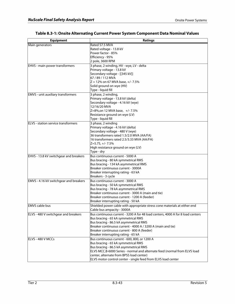
NuScale Final Safety Analysis Report Onsite Power Systems
Table 8.3-1: Onsite Alternating Current Power System Component Data Nominal Values
Equipment RatingsMain generators Rated 57.5 MVA
Rated voltage - 13.8 kVPower factor - 85%Efficiency - 95%2 pole, 3600 RPM
EHVS - main power transformers 3 phase, 2 winding, HV - wye, LV - deltaPrimary voltage - 13.8 kVSecondary voltage - [[345 kV]]67 / 89 / 112 MVAZ = 12% on 67 MVA base, +/- 7.5%Solid ground on wye (HV)Type - liquid fill
EMVS - unit auxiliary transformers 3 phase, 2 winding, Primary voltage - 13.8 kV (delta)Secondary voltage - 4.16 kV (wye)12/16/20 MVAZ=8%,on 12 MVA base, +/- 7.5%Resistance ground on wye (LV)Type - liquid fill
ELVS - station service transformers 3 phase, 2 windingPrimary voltage - 4.16 kV (delta)Secondary voltage - 480 V (wye) 36 transformers rated 1.5/2.0 MVA (AA/FA)16 transformers rated 2.5/3.33 MVA (AA/FA)Z=5.75, +/- 7.5%High resistance ground on wye (LV)Type - dry
EHVS - 13.8 kV switchgear and breakers Bus continuous current - 5000 ABus bracing - 80 kA symmetrical RMSBus bracing - 134 kA asymmetrical RMSBreaker continuous current - 3000ABreaker interrupting rating - 63 kABreakers - 3 cycle
EMVS - 4.16 kV switchgear and breakers Bus continuous current - 3000 ABus bracing - 50 kA symmetrical RMSBus bracing - 78 kA asymmetrical RMSBreaker continuous current - 3000 A (main and tie)Breaker continuous current - 1200 A (feeder)Breaker interrupting rating - 50 kA
EMVS cable bus Shielded power cable with appropriate stress cone materials at either endCable bus ampacity - 3000A
ELVS - 480 V switchgear and breakers Bus continuous current - 3200 A for 48 load centers, 4000 A for 8 load centersBus bracing - 65 kA symmetrical RMSBus bracing - 86.5 kA asymmetrical RMSBreaker continuous current - 4000 A / 3200 A (main and tie)
Tier 2 8.3-43 Revision 5
Breaker continuous current - 800 A (feeder)Breaker interrupting rating - 65 kA
ELVS - 480 V MCCs Bus continuous current - 600, 800, or 1200 ABus bracing - 65 kA symmetrical RMSBus bracing - 86.5 kA asymmetrical RMSELVS MCC.B-6000 Series - normal and alternate feed (normal from ELVS load center, alternate from BPSS load center)ELVS motor control center - single feed from ELVS load center

NuScale Final Safety Analysis Report Onsite Power Systems
Table 8.3-2: Backup Diesel Generator Nominal Loads
Load Description Required #of Equipment
Rated Voltage(Vac)
Operating Load(kVA)
Total Load(kVA)
Chemical and volume control system (CVCS) - Makeup pump (50 hp)
1 460 48.76 48.76
Containment flooding and drain system(CFDS) - Centrifugal pump (10 hp)
1 460 9.75 9.75
EDSS-MS division I, channel A - battery charger 6.25 kW, 125 Vdc, 24 hr
1 per module 480 9.30 111.60
EDSS-MS division I, channel C - battery charger 9.375 kW, 125 Vdc, 72 hr
1 per module 480 13.90 166.80
EDSS-MS division II, channel B - battery charger 9.375 kW, 125 Vdc, 72 hr
1 per module 480 13.90 166.80
EDSS-MS division II, channel D - battery charger 6.25 kW, 125 Vdc, 24 hr
1 per module 480 9.30 111.60
EDSS-C division I Common - battery charger 12.5 kW, 125 Vdc, 72 hr
1 480 18.50 18.50
EDSS-C division II Common - battery charger 12.5 kW, 125 Vdc, 72 hr
1 480 18.50 18.50
Process Sampling System (PSS) - Containment Sampling System (CSS) load (5 hp)
12 480 4.88 58.56
Boron addition - boric acid supply pump (5 hp) 1 460 4.88 4.88CHWS - CRVS standby CHWS chiller (267.8 kW) 1 480 315.06 315.06CHWS - CRVS standby CHWS chiller remote condensing unit (20.40 kW)
2 460 24.00 48.00
CHWS - CRVS standby chiller chilled water pump (5 hp)
1 460 4.88 4.88
CRVS - CRVS supply air handling unit A&B (75 hp) 1 460 73.14 73.14CRVS - CRVS supply air handling unit - preheat coil A&B (168 kW)
1 480 168 168
CRVS - CRVS filter unit fan motor (20 hp) 1 460 19.50 19.50CRVS - CRVS filter unit heating coil (148 kW) 1 480 148.00 148.00EDNS - RXB North - regulating transformer 480: 120/208 Vac, 225 kVA
1 480 50.29 50.29
EDNS - RXB South - regulating transformer 480: 120/208 Vac, 225 kVA
1 480 50.29 50.29
EDNS - CRB - regulating transformer 480: 120/208 Vac, 100 kVA
1 480 72.12 72.12
EDNS - RWB - regulating transformer 480: 120/208 Vac, 25 kVA
1 480 10.59 10.59
RBVS - MPS & battery room air supply fan (5 HP) 1 per module 460 4.88 58.56RBVS - MPS & battery room DX coil condenser (11.71 kVA)
1 per module 460 13.57 162.84
Tier 2 8.3-44 Revision 5

NuScale Final Safety Analysis Report Onsite Power Systems
Table 8.3-3: Highly Reliable Direct Current Power System Major Component Data Nominal Values
Battery
EDSS - MS (RXB - Elev. 75 ft)
A/D Channels - 542 AH to 1.75 VPC, 24-hr discharge
B/C Channels - 1039 AH to 1.75 VPC, 72-hr discharge
Battery
EDSS - C (CRB - Elev 50 ft)
Div I /Div II - 2303 AH to 1.75 VPC, 72-hr discharge
Battery Charger
EDSS - MS (RXB Bldg - Elev 86 ft)
A/D Channels - 6.25 kW, 50 A DC output
B/C Channels - 9.375 kW, 75 A DC output
Battery Charger
EDSS - C (CRB - Elev 50 ft)
Div I /Div II - 12.5 kW, 100 A DC output
DC Switchgear
EDSS - MS (RXB Bldg - Elev 86 ft)
A/D Channels -100 A
B/C Channels - 225 A
DC Switchgear
EDSS - C (CRB - Elev 50 ft)
Div I /Div II - 225 A
Battery Monitor
EDSS - MS (RXB - Elev 75 ft)
EDSS - C(CRB - Elev 50 ft)
Continuously monitors battery performance and provides alarms for battery discharges, voltage excursions, and temperature deviations exceeding tolerances.
Fused Disconnect Switch
EDSS - MS(RXB - Elev 86 ft)
EDSS - C(CRB - Elev 50 ft)
Provides a means to disconnect feeder and branch circuits. Switches include fusible overcurrent protection.
Fused Transfer Switch
EDSS - MS(RXB - Elev 75 ft)
EDSS-C(CRB - Elev 50 ft)
Provides a means to manually establish connection between battery and DC bus, battery test terminals, or battery charger. Switches include fusible overcurrent protection.
Tier 2 8.3-45 Revision 5
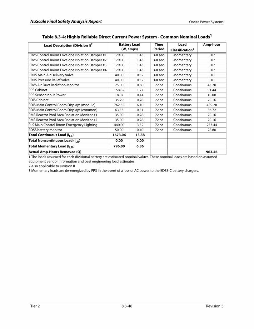
NuScale Final Safety Analysis Report Onsite Power Systems
Table 8.3-4: Highly Reliable Direct Current Power System - Common Nominal Loads1
Load Description (Division I)2 Battery Load(W, amps)
Time Period
Load Classification3
Amp-hour
CRVS Control Room Envelope Isolation Damper #1 179.00 1.43 60 sec Momentary 0.02CRVS Control Room Envelope Isolation Damper #2 179.00 1.43 60 sec Momentary 0.02CRVS Control Room Envelope Isolation Damper #3 179.00 1.43 60 sec Momentary 0.02CRVS Control Room Envelope Isolation Damper #4 179.00 1.43 60 sec Momentary 0.02CRHS Main Air Delivery Valve 40.00 0.32 60 sec Momentary 0.01CRHS Pressure Relief Valve 40.00 0.32 60 sec Momentary 0.01CRVS Air Duct Radiation Monitor 75.00 0.60 72 hr Continuous 43.20PPS Cabinet 158.82 1.27 72 hr Continuous 91.44PPS Sensor Input Power 18.07 0.14 72 hr Continuous 10.08SDIS Cabinet 35.29 0.28 72 hr Continuous 20.16SDIS Main Control Room Displays (module) 762.35 6.10 72 hr Continuous 439.20SDIS Main Control Room Displays (common) 63.53 0.51 72 hr Continuous 36.72RMS Reactor Pool Area Radiation Monitor #1 35.00 0.28 72 hr Continuous 20.16RMS Reactor Pool Area Radiation Monitor #2 35.00 0.28 72 hr Continuous 20.16PLS Main Control Room Emergency Lighting 440.00 3.52 72 hr Continuous 253.44EDSS battery monitor 50.00 0.40 72 hr Continuous 28.80Total Continuous Load (ILC) 1673.06 13.38Total Noncontinuous Load (ILN) 0.00 0.00Total Momentary Load (ILM) 796.00 6.36Actual Amp-Hours Removed (Q) 963.461 The loads assumed for each divisional battery are estimated nominal values. These nominal loads are based on assumed equipment vendor information and best engineering load estimates.2 Also applicable to Division II3 Momentary loads are de-energized by PPS in the event of a loss of AC power to the EDSS-C battery chargers.
Tier 2 8.3-46 Revision 5

NuScale Final Safety Analysis Report Onsite Power Systems
Table 8.3-5: Highly Reliable Direct Current Power System - Module Specific Nominal Loads1
Load Description Load (W, amps)
Time Period
Load Classification2
Amp-hour
EDSS-MS Nominal Loads (Channel A)3
CVCS Makeup Containment Isolation Valve (CIV) 100.00 0.80 60 sec Momentary 0.01CVCS Letdown CIV 100.00 0.80 60 sec Momentary 0.01CVCS PZR Spray CIV 100.00 0.80 60 sec Momentary 0.01CVCS High Point Degas CIV 100.00 0.80 60 sec Momentary 0.01Main Steam CIV 100.00 0.80 60 sec Momentary 0.01
Main Steam Bypass CIV4 0.00 0.00 - - 0.00
DHRS Actuation Valve 1 100.00 0.80 60 sec Momentary 0.01DHRS Actuation Valve 2 100.00 0.80 60 sec Momentary 0.01CES CIC 100.00 0.80 60 sec Momentary 0.01RCCWS Supply CIV 100.00 0.80 60 sec Momentary 0.01RCCWS Return CIV 100.00 0.80 60 sec Momentary 0.01CFDS CIV 100.00 0.80 60 sec Momentary 0.01FWS CIV 100.00 0.80 60 sec Momentary 0.01ECCS Reactor Recirculation Valve (RRV) 250.00 2.00 24 hr Continuous 48.00ECCS Reactor Vent Valve (RVV) #1 250.00 2.00 24 hr Continuous 48.00ECCS Reactor Vent Valve (RVV) #3 250.00 2.00 24 hr Continuous 48.00MPS Cabinet (SC/TD) 89.41 0.72 24 hr Continuous 17.28MPS Cabinet (Gateway) 104.71 0.84 24 hr Continuous 20.16MPS Cabinet (RTS/ESFAS) 176.47 1.41 24 hr Continuous 33.84MPS Sensor Input Power 60.59 0.48 24 hr Continuous 11.52NMS Cabinet 100.00 0.80 24 hr Continuous 19.20EDSS Battery Monitor 50.00 0.40 24 hr Continuous 9.60Total Continuous Load (ILC) 1331.18 10.65Total Noncontinuous Load (ILN) 0.00 0.00Total Momentary Load (ILM) 1200.00 9.60Actual Amp-Hours Removed (Q) 255.72
EDSS-MS Nominal Loads (Channel C)5
CVCS Makeup CIV 100.00 0.80 60 sec Momentary 0.01CVCS Letdown CIV 100.00 0.80 60 sec Momentary 0.01CVCS PZR Spray CIV 100.00 0.80 60 sec Momentary 0.01CVCS High Point Degas CIV 100.00 0.80 60 sec Momentary 0.01Main Steam CIV 100.00 0.80 60 sec Momentary 0.01
Main Steam Bypass CIV4 0.00 0.00 - - 0.00
DHRS Actuation Valve 1 100.00 0.80 60 sec Momentary 0.01DHRS Actuation Valve 2 100.00 0.80 60 sec Momentary 0.01
Tier 2 8.3-47 Revision 5
CES CIV 100.00 0.80 60 sec Momentary 0.01RCCWS Supply CIV 100.00 0.80 60 sec Momentary 0.01RCCWS Return CIV 100.00 0.80 60 sec Momentary 0.01CFDS CIV 100.00 0.80 60 sec Momentary 0.01FWS CIV 100.00 0.80 60 sec Momentary 0.01ECCS Reactor Recirculation Valve (RRV) 250.00 2.00 24 hr Noncontinuous 48.00ECCS Reactor Vent Valve (RVV) #1 250.00 2.00 24 hr Noncontinuous 48.00ECCS Reactor Vent Valve (RVV) #3 250.00 2.00 24 hr Noncontinuous 48.00MPS Cabinet (SC/TD) 118.82 0.95 72 hr Continuous 68.40MPS Cabinet (Gateway) 104.71 0.84 72 hr Continuous 60.48

NuScale Final Safety Analysis Report Onsite Power Systems
MPS Cabinet (RTS/ESFAS) 176.47 1.41 24 hr Noncontinuous 33.84MPS Sensor Input Power 60.59 0.48 72 hr Continuous 34.56NMS Cabinet 100.00 0.80 72 hr Continuous 57.60RMS Bioshield Radiation Monitor 120.00 0.96 72 hr Continuous 69.12EDSS Battery Monitor 50.00 0.40 72 hr Continuous 28.80Total Continuous Load (ILC) 554.12 4.43Total Noncontinuous Load (ILN) 926.47 7.41Total Momentary Load (ILM) 1200.00 9.60Actual Amp-Hours Removed (Q) 496.921 The loads assumed for each divisional battery are estimated nominal values. These nominal loads are based on assumed
equipment vendor information and best engineering load estimates.2 Momentary loads are de-energized by MPS in the event of a loss of AC power to the EDSS-MS battery chargers.3 Also applicable to Channel D4 Main steam bypass CIVs are considered to be de-energized during normal operation.5 Also applicable to Channel B
Table 8.3-5: Highly Reliable Direct Current Power System - Module Specific Nominal Loads1 (Continued)
Load Description Load (W, amps)
Time Period
Load Classification2
Amp-hour
Tier 2 8.3-48 Revision 5
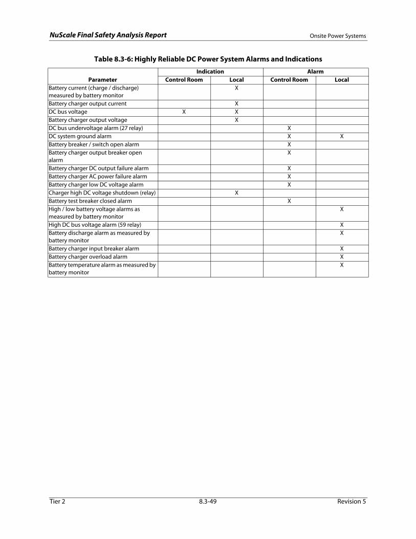
NuScale Final Safety Analysis Report Onsite Power Systems
Table 8.3-6: Highly Reliable DC Power System Alarms and Indications
Indication AlarmParameter Control Room Local Control Room Local
Battery current (charge / discharge) measured by battery monitor
X
Battery charger output current XDC bus voltage X XBattery charger output voltage XDC bus undervoltage alarm (27 relay) XDC system ground alarm X XBattery breaker / switch open alarm XBattery charger output breaker open alarm
X
Battery charger DC output failure alarm XBattery charger AC power failure alarm XBattery charger low DC voltage alarm XCharger high DC voltage shutdown (relay) XBattery test breaker closed alarm XHigh / low battery voltage alarms as measured by battery monitor
X
High DC bus voltage alarm (59 relay) XBattery discharge alarm as measured by battery monitor
X
Battery charger input breaker alarm XBattery charger overload alarm XBattery temperature alarm as measured by battery monitor
X
Tier 2 8.3-49 Revision 5
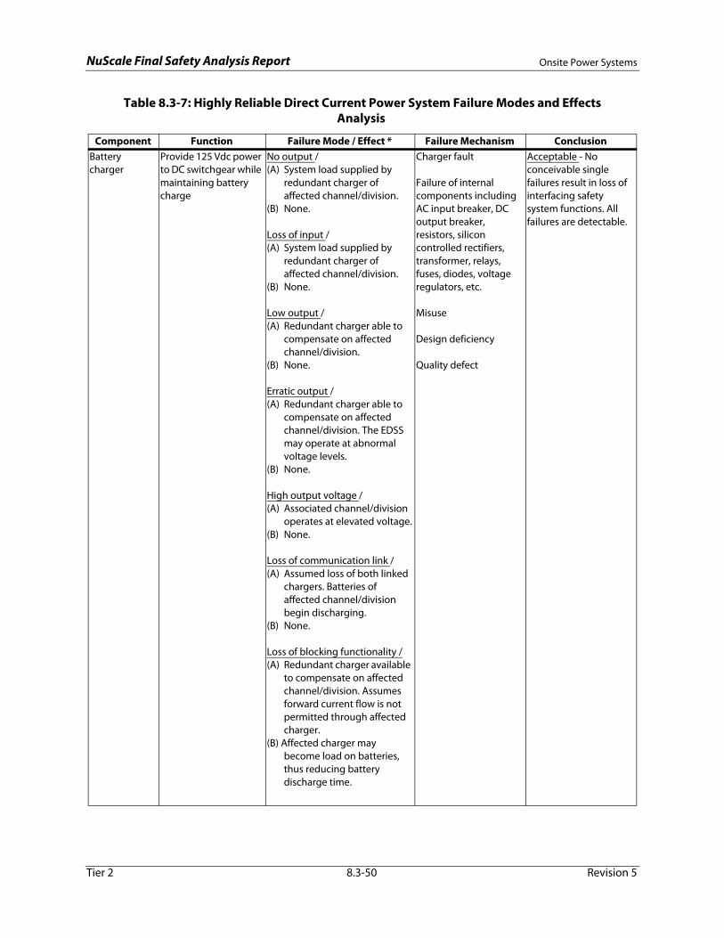
NuScale Final Safety Analysis Report Onsite Power Systems
Table 8.3-7: Highly Reliable Direct Current Power System Failure Modes and Effects Analysis
Component Function Failure Mode / Effect * Failure Mechanism ConclusionBattery charger
Provide 125 Vdc power to DC switchgear while maintaining battery charge
No output /(A) System load supplied by
redundant charger of affected channel/division.
(B) None.
Loss of input /(A) System load supplied by
redundant charger of affected channel/division.
(B) None.
Low output /(A) Redundant charger able to
compensate on affected channel/division.
(B) None.
Erratic output /(A) Redundant charger able to
compensate on affected channel/division. The EDSS may operate at abnormal voltage levels.
(B) None.
High output voltage /(A) Associated channel/division
operates at elevated voltage.(B) None.
Loss of communication link /(A) Assumed loss of both linked
chargers. Batteries of affected channel/division begin discharging.
(B) None.
Loss of blocking functionality /(A) Redundant charger available
to compensate on affected channel/division. Assumes forward current flow is not
Charger fault
Failure of internal components including AC input breaker, DC output breaker, resistors, silicon controlled rectifiers, transformer, relays, fuses, diodes, voltage regulators, etc.
Misuse
Design deficiency
Quality defect
Acceptable - No conceivable single failures result in loss of interfacing safety system functions. All failures are detectable.
Tier 2 8.3-50 Revision 5
permitted through affected charger.
(B) Affected charger may become load on batteries, thus reducing battery discharge time.
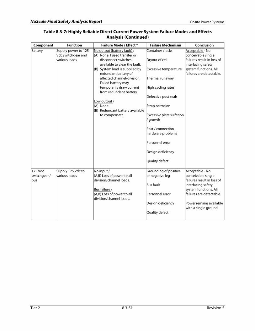
NuScale Final Safety Analysis Report Onsite Power Systems
Battery Supply power to 125 Vdc switchgear and various loads
No output (battery fault) /(A) None. Fused transfer or
disconnect switches available to clear the fault.
(B) System load is supplied by redundant battery of affected channel/division. Failed battery may temporarily draw current from redundant battery.
Low output /(A) None. (B) Redundant battery available
to compensate.
Container cracks
Dryout of cell
Excessive temperature
Thermal runaway
High cycling rates
Defective post seals
Strap corrosion
Excessive plate sulfation / growth
Post / connection hardware problems
Personnel error
Design deficiency
Quality defect
Acceptable - No conceivable single failures result in loss of interfacing safety system functions. All failures are detectable.
125 Vdc switchgear / bus
Supply 125 Vdc to various loads
No input /(A,B) Loss of power to all division/channel loads.
Bus failure /(A,B) Loss of power to all division/channel loads.
Grounding of positive or negative leg
Bus fault
Personnel error
Design deficiency
Quality defect
Acceptable - No conceivable single failures result in loss of interfacing safety system functions. All failures are detectable.
Power remains available with a single ground.
Table 8.3-7: Highly Reliable Direct Current Power System Failure Modes and Effects Analysis (Continued)
Component Function Failure Mode / Effect * Failure Mechanism Conclusion
Tier 2 8.3-51 Revision 5

NuScale Final Safety Analysis Report Onsite Power Systems
Fused transfer switch
Provide continuity or point isolation from battery, test connection, or battery charger
Indavertent opening (blown fuse) /(A) Reduced load on battery
chargers.(B) System load supplied by
redundant battery of affected channel/division.
Fails to interrupt / (A,B) Fusible disconnect located between transfer switch and DC bus available to clear/interrupt.
Wear / fatigue/ deformation / degradation of fuse holder
Corrosion
Oxidation
Equipment load cycling
Heat generated by surrounding components
Embrittlement of fuse element
Personnel error
Design deficiency
Quality defect
Acceptable - No conceivable single failures result in safety system actuation or loss of interfacing safety system functions. All failures are detectable.
Table 8.3-7: Highly Reliable Direct Current Power System Failure Modes and Effects Analysis (Continued)
Component Function Failure Mode / Effect * Failure Mechanism Conclusion
Tier 2 8.3-52 Revision 5
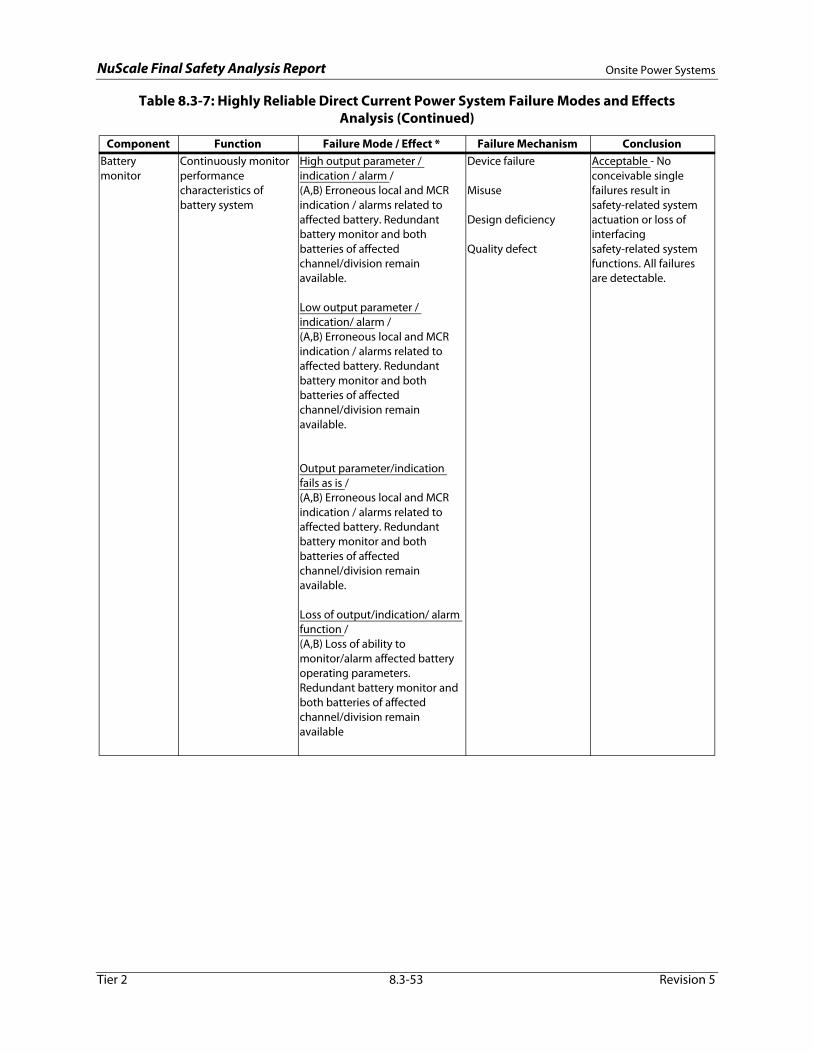
NuScale Final Safety Analysis Report Onsite Power Systems
Battery monitor
Continuously monitor performance characteristics of battery system
High output parameter / indication / alarm / (A,B) Erroneous local and MCR indication / alarms related to affected battery. Redundant battery monitor and both batteries of affected channel/division remain available.
Low output parameter / indication/ alarm / (A,B) Erroneous local and MCR indication / alarms related to affected battery. Redundant battery monitor and both batteries of affected channel/division remain available.
Output parameter/indication fails as is / (A,B) Erroneous local and MCR indication / alarms related to affected battery. Redundant battery monitor and both batteries of affected channel/division remain available.
Loss of output/indication/ alarm function /(A,B) Loss of ability to monitor/alarm affected battery operating parameters. Redundant battery monitor and both batteries of affected channel/division remain available
Device failure
Misuse
Design deficiency
Quality defect
Acceptable - No conceivable single failures result in safety-related system actuation or loss of interfacing safety-related system functions. All failures are detectable.
Table 8.3-7: Highly Reliable Direct Current Power System Failure Modes and Effects Analysis (Continued)
Component Function Failure Mode / Effect * Failure Mechanism Conclusion
Tier 2 8.3-53 Revision 5
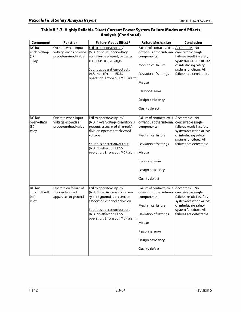
NuScale Final Safety Analysis Report Onsite Power Systems
DC bus undervoltage (27) relay
Operate when input voltage drops below a predetermined value
Fail to operate/output / (A,B) None. If undervoltage condition is present, batteries continue to discharge.
Spurious operation/output / (A,B) No effect on EDSS operation. Erroneous MCR alarm.
Failure of contacts, coils, or various other internal components
Mechanical failure
Deviation of settings
Misuse
Personnel error
Design deficiency
Quality defect
Acceptable - No conceivable single failures result in safety system actuation or loss of interfacing safety system functions. All failures are detectable.
DC bus overvoltage (59)relay
Operate when input voltage exceeds a predetermined value
Fail to operate/output / (A,B) If overvoltage condition is present, associated channel / division operates at elevated voltage.
Spurious operation/output / (A,B) No effect on EDSS operation. Erroneous MCR alarm.
Failure of contacts, coils, or various other internal components
Mechanical failure
Deviation of settings
Misuse
Personnel error
Design deficiency
Quality defect
Acceptable - No conceivable single failures result in safety system actuation or loss of interfacing safety system functions. All failures are detectable.
DC bus ground fault (64)relay
Operate on failure of the insulation of apparatus to ground
Fail to operate/output / (A,B) None. Assumes only one system ground is present on associated channel / division.
Spurious operation/output / (A,B) No effect on EDSS operation. Erroneous MCR alarm.
Failure of contacts, coils, or various other internal components
Mechanical failure
Deviation of settings
Misuse
Personnel error
Acceptable - No conceivable single failures result in safety system actuation or loss of interfacing safety system functions. All failures are detectable.
Table 8.3-7: Highly Reliable Direct Current Power System Failure Modes and Effects Analysis (Continued)
Component Function Failure Mode / Effect * Failure Mechanism Conclusion
Tier 2 8.3-54 Revision 5
Design deficiency
Quality defect

NuScale Final Safety Analysis Report Onsite Power Systems
DC bus voltmeter
Continuously measure DC bus voltage
Low output / (A,B) No effect on EDSS operation. Erroneous local/remote PAM (Type D variable) indication for associated DC bus.
High output / (A,B) No effect on EDSS operation. Erroneous local/remote PAM (Type D variable) indication for associated DC bus.
Fail as-is / (A,B) No effect on EDSS operation. Erroneous local/remote PAM (Type D variable) indication for associated DC bus.
Misuse
Personnel error
Design deficiency
Quality defect
Acceptable - No conceivable single failures result in safety system actuation or loss of interfacing safety system functions. All failures are detectable.
Battery charger ammeter
Continuously measure DC current
Low output / (A,B) No effect on EDSS operation. Upstream battery charger provides DC current indication / measurement.
High output / (A,B) No effect on EDSS operation. Upstream battery charger provides DC current indication / measurement.
Fail as-is / (A,B) No effect on EDSS operation. Upstream battery charger provides DC current indication / measurement.
Misuse
Personnel error
Design deficiency
Quality defect
Acceptable - No conceivable single failures result in safety system actuation or loss of interfacing safety system functions. All failures are detectable.
Table 8.3-7: Highly Reliable Direct Current Power System Failure Modes and Effects Analysis (Continued)
Component Function Failure Mode / Effect * Failure Mechanism Conclusion
Tier 2 8.3-55 Revision 5

NuScale Final Safety Analysis Report Onsite Power Systems
Fusible disconnectcharger-to-bus
Provide circuit continuity and protection between DC bus and associated load
Spurious operation (blown fuse)/
(A) Loss of ability to supply DC bus from upstream battery charger. DC bus supplied by redundant charger of affected channel/division.
(B) None.
Fails to close /(A) Loss of ability to supply DC
bus from upstream battery charger. DC bus supplied by redundant charger of affected channel/division.
(B) None.
Fails to open /(A) Continued loading on
battery charger. Upstream battery charger output breaker available to open/clear/interrupt.
(B) None. Upstream battery charger output breaker available to open/interrupt.
Fails to interrupt on opening /(A) Continued loading on
battery charger. Upstream battery charger output breaker available to open/clear/interrupt.
(B) None. Upstream battery charger output breaker available to open/interrupt.
Wear / fatigue/ deformation / degradation of fuse holder
Corrosion
Oxidation
Equipment load cycling
Heat generated by surrounding components
Embrittlement of fuse element
Misuse
Design deficiency
Quality defect
Acceptable - No conceivable single failures result in safety system actuation or loss of interfacing safety system functions. All failures are detectable.
Table 8.3-7: Highly Reliable Direct Current Power System Failure Modes and Effects Analysis (Continued)
Component Function Failure Mode / Effect * Failure Mechanism Conclusion
Tier 2 8.3-56 Revision 5

NuScale Final Safety Analysis Report Onsite Power Systems
Fusible disconnecttransfer switch- to- bus
Provide circuit continuity and protection between battery transfer switch and DC bus
Spurious operation (blown fuse)/(A) Reduced load on battery
chargers. (B) DC bus supplied by
redundant battery of affected channel/division
Fails to close /(A) Reduced load on battery
chargers. (B) DC bus supplied by
redundant battery of affected channel/division
Fails to open /(A) Continued float charging of
battery. Upstream transfer switch located between battery and fusible disconnect available to open/interrupt.
(B) Continued loading on battery. Upstream transfer switch located between battery and fusible disconnect available to open/interrupt.
Fails to interrupt on opening /(A) Continued float charging of
battery. Upstream transfer switch located between battery and fusible disconnect available to open/interrupt.
(B) Continued loading on battery. Upstream transfer switch located between battery and fusible disconnect available to open/interrupt.
Wear / fatigue/ deformation / degradation of fuse holder
Corrosion
Oxidation
Equipment load cycling
Heat generated by surrounding components
Embrittlement of fuse element
Misuse
Design deficiency
Quality defect
Acceptable - No conceivable single failures result in safety system actuation or loss of interfacing safety system functions. All failures are detectable.
Table 8.3-7: Highly Reliable Direct Current Power System Failure Modes and Effects Analysis (Continued)
Component Function Failure Mode / Effect * Failure Mechanism Conclusion
Tier 2 8.3-57 Revision 5
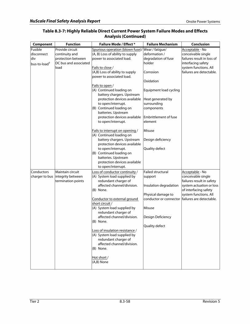
NuScale Final Safety Analysis Report Onsite Power Systems
Fusible disconnectdiv bus-to-load†
Provide circuit continuity and protection between DC bus and associated load
Spurious operation (blown fuse)/(A, B) Loss of ability to supply power to associated load.
Fails to close /(A,B) Loss of ability to supply power to associated load.
Fails to open /(A) Continued loading on
battery chargers. Upstream protection devices available to open/interrupt.
(B) Continued loading on batteries. Upstream protection devices available to open/interrupt.
Fails to interrupt on opening /(A) Continued loading on
battery chargers. Upstream protection devices available to open/interrupt.
(B) Continued loading on batteries. Upstream protection devices available to open/interrupt.
Wear / fatigue/ deformation / degradation of fuse holder
Corrosion
Oxidation
Equipment load cycling
Heat generated by surrounding components
Embrittlement of fuse element
Misuse
Design deficiency
Quality defect
Acceptable - No conceivable single failures result in loss of interfacing safety system functions. All failures are detectable.
Conductorscharger to bus
Maintain circuit integrity between termination points
Loss of conductor continuity /(A) System load supplied by
redundant charger of affected channel/division.
(B) None.
Conductor to external ground short circuit /(A) System load supplied by
redundant charger of affected channel/division.
(B) None.
Loss of insulation resistance /(A) System load supplied by
redundant charger of affected channel/division.
Failed structural support
Insulation degradation
Physical damage to conductor or connector
Misuse
Design Deficiency
Quality defect
Acceptable - No conceivable single failures result in safety system actuation or loss of interfacing safety system functions. All failures are detectable.
Table 8.3-7: Highly Reliable Direct Current Power System Failure Modes and Effects Analysis (Continued)
Component Function Failure Mode / Effect * Failure Mechanism Conclusion
Tier 2 8.3-58 Revision 5
(B) None.
Hot short /(A,B) None
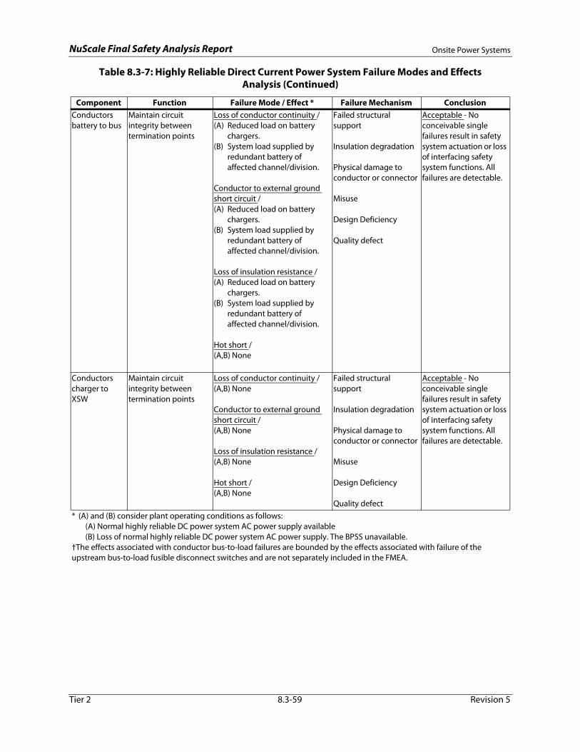
NuScale Final Safety Analysis Report Onsite Power Systems
Conductorsbattery to bus
Maintain circuit integrity between termination points
Loss of conductor continuity /(A) Reduced load on battery
chargers. (B) System load supplied by
redundant battery of affected channel/division.
Conductor to external ground short circuit /(A) Reduced load on battery
chargers. (B) System load supplied by
redundant battery of affected channel/division.
Loss of insulation resistance /(A) Reduced load on battery
chargers. (B) System load supplied by
redundant battery of affected channel/division.
Hot short /(A,B) None
Failed structural support
Insulation degradation
Physical damage to conductor or connector
Misuse
Design Deficiency
Quality defect
Acceptable - No conceivable single failures result in safety system actuation or loss of interfacing safety system functions. All failures are detectable.
Conductorscharger to XSW
Maintain circuit integrity between termination points
Loss of conductor continuity /(A,B) None
Conductor to external ground short circuit /(A,B) None
Loss of insulation resistance /(A,B) None
Hot short /(A,B) None
Failed structural support
Insulation degradation
Physical damage to conductor or connector
Misuse
Design Deficiency
Quality defect
Acceptable - No conceivable single failures result in safety system actuation or loss of interfacing safety system functions. All failures are detectable.
* (A) and (B) consider plant operating conditions as follows: (A) Normal highly reliable DC power system AC power supply available (B) Loss of normal highly reliable DC power system AC power supply. The BPSS unavailable.†The effects associated with conductor bus-to-load failures are bounded by the effects associated with failure of the upstream bus-to-load fusible disconnect switches and are not separately included in the FMEA.
Table 8.3-7: Highly Reliable Direct Current Power System Failure Modes and Effects Analysis (Continued)
Component Function Failure Mode / Effect * Failure Mechanism Conclusion
Tier 2 8.3-59 Revision 5

NuScale Final Safety Analysis Report Onsite Power Systems
Table 8.3-8: Normal Direct Current Power System Major Component Data Nominal Values
EDNS Component EDNS Subsystem(s) Nominal ValuesVRLA batteries All Type: VRLA
RXB North/South Single string, 120 cells, 250 Vdc1080 AH at 8-hour rate to 1.75 V/cell at 77°F discharge rate
CRB Single string, 60 cells, 125 Vdc1320 AH at 8-hour rate to 1.75 V/cell at 77°F discharge rate
RWB Single string, 60 cells, 125 Vdc345 AH at 8-hour rate to 1.75 V/cell at 77°F discharge rate
Turbine Building North/South Single string, 120 cells, 250 Vdc1320 AH at 8-hour rate to 1.75 V/cell at 77°F discharge rate
Yard PDC 1/PDC 2 Two strings, 60 cells/string, 125 Vdc2160 AH at 8-hour rate to 1.75 V/cell at 77°F discharge rate
Yard PDC 3/PDC 4 Single string, 60 cells, 125 Vdc1080 AH at 8-hour rate to 1.75 V/cell at 77°F discharge rate
Yard PDC 5/PDC 6 Single string, 60 cells, 125 Vdc480 AH at 8-hour rate to 1.75 V/cell at 77°F discharge rate
Yard PDC 7/PDC 8 Single string, 60 cells, 125 Vdc345 AH at 8-hour rate to 1.75 V/cell at 77°F discharge rate
Battery chargers All Input voltage: 480 Vac, 3-phaseRXB North/South Output voltage: 250 Vdc
Output current: 800 ACRB Output voltage: 125 Vdc
Output current: 800 ARWB Output voltage: 125 Vdc
Output current: 150 ATurbine Building North/South Output voltage: 250 Vdc
Output current: 800 AYard PDC 1/PDC 2 Output voltage: 125 Vdc
Output current: 300 AYard PDC 3/PDC 4 Output voltage: 125 Vdc
Output current: 200 AYard PDC 5/PDC 6 Output voltage: 125 Vdc
Output current: 150 AYard PDC 7/PDC 8 Output voltage: 125 Vdc
Output current: 200 ADC distribution buses All Individual bus ratings specified below
RXB North/South Bus voltage: 250 VdcCurrent rating: 1200 A
CRB Bus voltage: 125 VdcCurrent rating: 1200 A
RWB Bus voltage: 125 VdcCurrent rating: 400 A
Tier 2 8.3-60 Revision 5
Turbine Building North/South Bus voltage: 250 VdcCurrent rating: 1200 A
Yard PDC 1/PDC 2 Bus voltage: 125 VdcCurrent rating: 600 A
Yard PDC 3/PDC 4 Bus voltage: 125 VdcCurrent rating: 400 A
Yard PDC 5/PDC 6 Bus voltage: 125 VdcCurrent rating: 400 A
Yard PDC 7/PDC 8 Bus voltage: 125 VdcCurrent rating: 400 A

NuScale Final Safety Analysis Report Onsite Power Systems
Inverters All Output voltage: 120/208 Vac, 3-phaseRXB North/South Input voltage: 250 Vdc
Rating: 200 KVACRB Input voltage: 125 Vdc
Rating: 100 KVARWB Input voltage: 125 Vdc
Rating: 20 KVATurbine Building North/South Input voltage: 250 Vdc
Rating: 40 KVAYard PDC 1/PDC 2 N/A - No DC-to-AC inversion in these EDNS subsystemsYard PDC 3/PDC 4 N/A - No DC-to-AC inversion in these EDNS subsystemsYard PDC 5/PDC 6 N/A - No DC-to-AC inversion in these EDNS subsystemsYard PDC 7/PDC 8 N/A - No DC-to-AC inversion in these EDNS subsystems
Voltage regulating transformers
All Input voltage: 480 VacOutput voltage: 120/208 Vac, 3-phase
RXB North/South Rating: 225 KVACRB Rating: 100 KVARWB Rating: 25 KVATurbine Building North/South Rating: 50 KVAYard PDC 1/PDC 2 N/A - No DC-to-AC inversion in these EDNS subsystemsYard PDC 3/PDC 4 N/A - No DC-to-AC inversion in these EDNS subsystemsYard PDC 5/PDC 6 N/A - No DC-to-AC inversion in these EDNS subsystemsYard PDC 7/PDC 8 N/A - No DC-to-AC inversion in these EDNS subsystems
AC distribution buses All -RXB North/South Current Rating: 800 ACRB Current Rating: 400 ARWB Current Rating: 225 ATurbine Building North/South Current Rating: 225 AYard PDC 1/PDC 2 N/A - No DC-to-AC inversion in these EDNS subsystemsYard PDC 3/PDC 4 N/A - No DC-to-AC inversion in these EDNS subsystemsYard PDC 5/PDC 6 N/A - No DC-to-AC inversion in these EDNS subsystemsYard PDC 7/PDC 8 N/A - No DC-to-AC inversion in these EDNS subsystems
Table 8.3-8: Normal Direct Current Power System Major Component Data Nominal Values (Continued)
EDNS Component EDNS Subsystem(s) Nominal Values
Tier 2 8.3-61 Revision 5
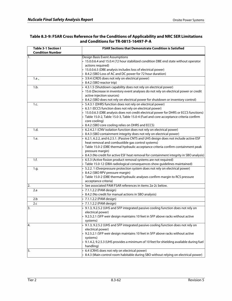
NuScale Final Safety Analysis Report Onsite Power Systems
Table 8.3-9: FSAR Cross Reference for the Conditions of Applicability and NRC SER Limitations and Conditions for TR-0815-16497-P-A
Table 3-1 Section I Condition Number
FSAR Sections that Demonstrate Condition is Satisfied
1. Design Basis Event Assumptions• 15.0.0.6.4 and 15.0.4 (72 hour stabilized condition DBE end state without operator
actions required)• 15.0.0.6.5 (DBE analysis includes loss of electrical power)• 8.4.2 (SBO Loss of AC and DC power for 72 hour duration)
1.a . • 3.9.4 (CRDS does not rely on electrical power)• 8.4.2 (SBO reactor trip)
1.b. • 4.3.1.5 (Shutdown capability does not rely on electrical power)• 15.6 (Decrease in inventory event analyses do not rely on electrical power or credit
active injection sources)• 8.4.2 (SBO does not rely on electrical power for shutdown or inventory control)
1.c. • 5.4.3.1 (DHRS function does not rely on electrical power)• 6.3.1 (ECCS function does not rely on electrical power)• 15.0.0.6.3 (DBE analysis does not credit electrical power for DHRS or ECCS functions)• Table 15.0-2, Table 15.0-3, Table 15.0-4 (Fuel and core acceptance criteria confirm
core cooling)• 8.4.2 (SBO core cooling relies on DHRS and ECCS)
1.d. • 6.2.4.2.1 (CNV isolation function does not rely on electrical power)• 8.4.3 (SBO containment integrity does not rely on electrical power)
1.e. • 6.2.1, 6.2.2, and 6.2.5.1. (Passive CNTS and UHS design does not include active ESF heat removal and combustible gas control systems)
• Table 15.0-2 (DBE thermal hydraulic acceptance criteria confirm containment peak pressure margin)
• 8.4.3 (No credit for active ESF heat removal for containment integrity in SBO analysis)1.f. • 6.5.3 (Active fission product removal systems are not required)
• Table 15.0-12 (DBA radiological consequences show guidelines maintained)1.g. • 5.2.2. 1 (Overpressure protection system does not rely on electrical power)
• 8.4.2 (SBO RPV pressure margin)• Table 15.0-2 (DBE thermal hydraulic analyses confirm margin to RCS pressure
acceptance criteria)2. • See associated PAM FSAR references in items 2a-2c below.
2.a • 7.1.1.2.2 (PAM design)• 8.4.2 (No credit for manual actions in SBO analysis)
2.b • 7.1.1.2.2 (PAM design)2.c • 7.1.1.2.2 (PAM design)
3. • 9.1.3, 9.2.5.2 (UHS and SFP integrated passive cooling function does not rely on electrical power)
• 9.2.5.2.1 (SFP weir design maintains 10 feet in SFP above racks without active systems)
4. • 9.1.3, 9.2.5.2 (UHS and SFP integrated passive cooling function does not rely on
Tier 2 8.3-62 Revision 5
electrical power)• 9.2.5.2.1 (SFP weir design maintains 10 feet in SFP above racks without active
systems)• 9.1.4.2, 9.2.5.3 (UHS provides a minimum of 10 feet for shielding available during fuel
handling)5. • 6.4 (CRHS does not rely on electrical power)
• 8.4.3 (Main control room habitable during SBO without relying on electrical power)
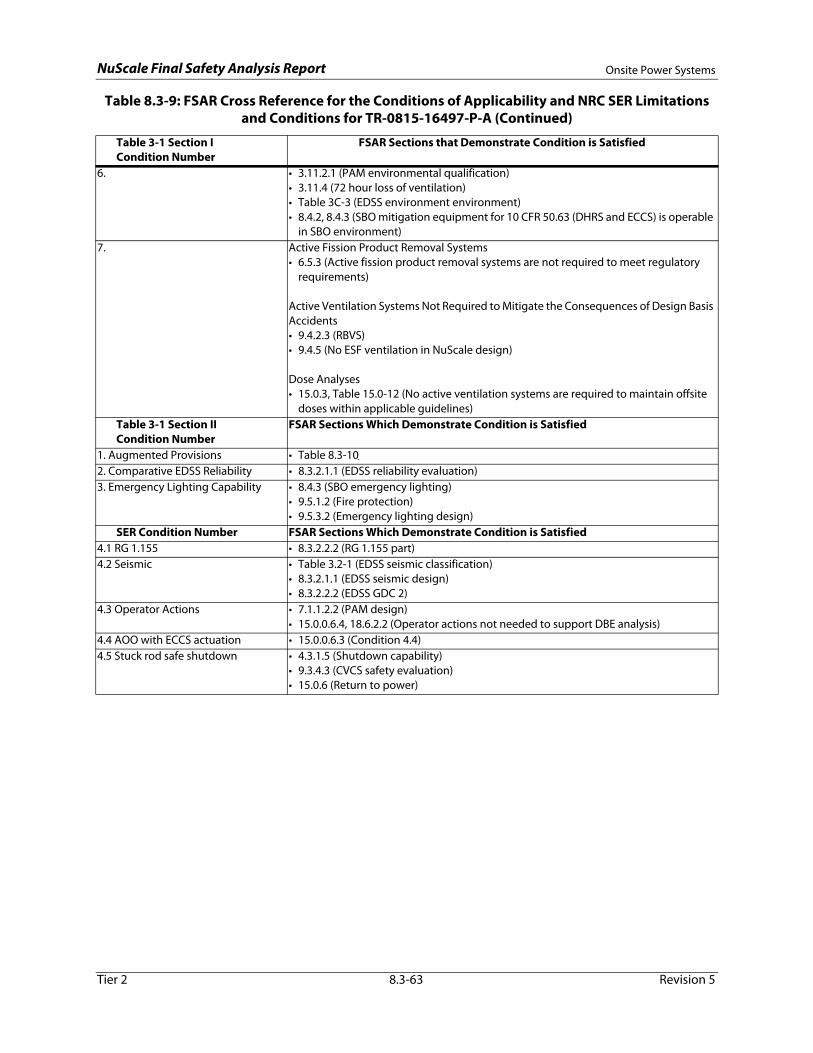
NuScale Final Safety Analysis Report Onsite Power Systems
6. • 3.11.2.1 (PAM environmental qualification)• 3.11.4 (72 hour loss of ventilation)• Table 3C-3 (EDSS environment environment)• 8.4.2, 8.4.3 (SBO mitigation equipment for 10 CFR 50.63 (DHRS and ECCS) is operable
in SBO environment)7. Active Fission Product Removal Systems
• 6.5.3 (Active fission product removal systems are not required to meet regulatory requirements)
Active Ventilation Systems Not Required to Mitigate the Consequences of Design Basis Accidents• 9.4.2.3 (RBVS)• 9.4.5 (No ESF ventilation in NuScale design)
Dose Analyses• 15.0.3, Table 15.0-12 (No active ventilation systems are required to maintain offsite
doses within applicable guidelines)Table 3-1 Section IICondition Number
FSAR Sections Which Demonstrate Condition is Satisfied
1. Augmented Provisions • Table 8.3-102. Comparative EDSS Reliability • 8.3.2.1.1 (EDSS reliability evaluation)3. Emergency Lighting Capability • 8.4.3 (SBO emergency lighting)
• 9.5.1.2 (Fire protection) • 9.5.3.2 (Emergency lighting design)
SER Condition Number FSAR Sections Which Demonstrate Condition is Satisfied4.1 RG 1.155 • 8.3.2.2.2 (RG 1.155 part)4.2 Seismic • Table 3.2-1 (EDSS seismic classification)
• 8.3.2.1.1 (EDSS seismic design) • 8.3.2.2.2 (EDSS GDC 2)
4.3 Operator Actions • 7.1.1.2.2 (PAM design)• 15.0.0.6.4, 18.6.2.2 (Operator actions not needed to support DBE analysis)
4.4 AOO with ECCS actuation • 15.0.0.6.3 (Condition 4.4)4.5 Stuck rod safe shutdown • 4.3.1.5 (Shutdown capability)
• 9.3.4.3 (CVCS safety evaluation)• 15.0.6 (Return to power)
Table 8.3-9: FSAR Cross Reference for the Conditions of Applicability and NRC SER Limitations and Conditions for TR-0815-16497-P-A (Continued)
Table 3-1 Section I Condition Number
FSAR Sections that Demonstrate Condition is Satisfied
Tier 2 8.3-63 Revision 5

NuScale Final Safety Analysis Report Onsite Power Systems
Table 8.3-10: FSAR Cross Reference for the EDSS Augmented Provisions in TR-0815-16497-P-A
Augmented Provision (Table 3-2 of Reference 8.3-1)
FSAR Sections Which Demonstrate that Condition is Satisfied
Compliance with 10 CFR 50.55a(1) and IEEE Standard 603-1991
• 8.3.2.2.2 (10 CFR 50.55a(h))
Safety Classification • 8.3.2.1.1• 8.3.2.2.2 (RG 1.32)
Quality Assurance • 8.3.2.2.2 (RG 1.155) Seismic Qualification • 8.3.2.1.1 (EDSS seismic design)
• 8.3.2.2.2 (GDC 2)Environmental Qualification • 8.3.2.2.2 (GDC 4)
• 3.11.2.1 (mild environments)• Appendix 3C and Table 3C-3 (EDSS rooms)
Batteries • 8.3.2.2.1 (Battery design)Onsite Standby Power Sources • 8.3.1.2.7 (SECY 94-084 and SECY 95-132)Identification • 8.3.2.1.1
• 8.3.2.2.2 (RG 1.32 and RG 1.75)Independence • 8.3.2.1.1
• 8.3.2.2.2 (10 CFR 50.55a(h), RG 1.32, RG 1.75, and RG 1.128)Single Failure Criterion • 8.3.2.1.1
• 8.3.2.2.2 (RG 1.32 and RG 1.53)Common Cause Failure • 8.3.2.1.1
• 8.3.2.2.2 (RG 1.32 and RG 1.53)Control of Access • 8.3.2.1.1
• 8.3.2.2.2 (RG 1.232)Protection • 8.3.2.2.3 (Equipment Protection)Power Quality • 8.3.2.2.3 (Power Quality)Location of Indicators and Controls • 8.3.2.2.2 (RG 1.32)
• 8.3.2.4Surveillance and Testing • 8.3.2.2.2 (RG 1.32, RG 1.41, RG 1.68, RG 1.118, RG 1.129, and Section 14.2) 8.3.2.3 Multi-Unit Station Considerations • 8.3.2.2.2 (RG 1.32 and 1.81, GDC 5)
Tier 2 8.3-64 Revision 5

NuScale Final Safety Analysis Report Onsite Power Systems
Figure 8.3-1: Station Single Line Diagram
(M2012) 4.16 kV
MODULE 2 MODULE 3 MODULE 4SITE COOLINGWATER PUMP
MOTOR A
1200 TONCHILLER
PACKAGE A
(M2013) 4.16 kV
MODULE 3 MODULE 4 MODULE 5SITE COOLINGWATER PUMP
MOTOR C
CIRCULATINGWATER PUMP
MOTOR B
(M2011) 4.16 kV
MODULE 1 MODULE 2
(M2014) 4.16 kV
MODULE 5 MODULE 6 MODULE 1
CIRCULATINGWATER PUMP
MOTOR C
MODULE 6TO
0A-BUS-L-3001 CIRCULATINGWATER PUMP
MOTOR A
TO0A-BUS-L-3002
1200 TONCHILLER PACKAGE C
TL
A BREAKER AND HALF SCHEME
SWITCH YARD
(H1011) 13.8 kV (H1012) 13.8 kV (H1013) 13.8 kV (H1014) 13.8 kV
XF3022 XF3024 XF3031 XF3033 XF3041 XF3043 XF3032 XF3034 XF3042 XF3044 XF3051 XF3053
XF3011 XF3013 XF3021 XF3023 XF3062 XF3064 XF3052 XF3054 XF3061 XF3063 XF3012 XF3014
2STG 3STG 1STG 6STG
UAT
XF2011
(M2022) 4.16 kV
MODULE 8 MODULE 9 MODULE 10
SITE COOLINGWATER PUMP
MOTOR B
1200 TONCHILLER
PACKAGE B
(M2023) 4.16 kV
MODULE 9 MODULE 10 MODULE 11
CIRCULATINGWATER PUMP B
(M2021) 4.16 kV
MODULE 7 MODULE 8
(M2024) 4.16 kV
MODULE 11 MODULE 12 MODULE 7
CIRCULATINGWATER PUMP A
MODULE 12TO
0B-BUS-L-3003 CIRCULATINGWATERPUMP C
TO0B-BUS-L-3004
(H1021) 13.8 kV
XF3082 XF3084 XF3091 XF3093 XF3101 XF3103 XF3092 XF3094 XF3102 XF3104 XF3111 XF3113
XF3071 XF3073 XF3081 XF3083 XF3122 XF3124 XF3112 XF3114 XF3121 XF3123 XF3072 XF3074
TL
345 kV
345 kV
UAT
XF2014
XF3001 XF3002 XF3003 XF3004
MPT
XF1011
MPT
XF1012
MPT
XF1013
MPT
XF1014
UAT
XF2012
UAT
XF2013
XF3005
TO0A-BUS-L-3005
XF3006
TO0A-BUS-L-3006
XF3008
TO0B-BUS-L-3008
XF3007
TO0B-BUS-L-3007
0A 0B
4STG 5STG
HMK LJIHMLKJI
AAPS
A TO BUS 1021
L1
L2
B TO BUS 2021
C TO BUS 2014
C TO BUS 2011
UAT
XF2024
UAT
XF2023
UAT
XF2022
UAT
XF2021
MPT
XF1024
MPT
XF1023
MPT
XF1021
MPT
XF1022
(H1024) 13.8 kV
12STG
NS
(H1023) 13.8 kV
10STG 11STG
Q R
8STG 9STG
O
(H1022) 13.8 kV
7STG
NSRQPO
A TO BUS 1011
P
B TO BUS 2011
D TO BUS 2024
D TO BUS 2021
Tier 2 8.3-65 Revision 5

NuScale Final Safety Analysis Report Onsite Power Systems
Figure 8.3-2a: 13.8kV and Switchyard System
N.O.
TO SWITCHYARDNOTE 1
TO SWITCHYARDNOTE 1
TO SWITCHYARDNOTE 1
TO SWITCHYARDNOTE 1
B C D E F
EMVS 0A UAT 1 EMVS 0A UAT 2 EMVS 0A UAT 3 EMVS 0A UAT 4
0A EHVSBUS 1 - 13.8kV
0A EHVSBUS 2 - 13.8kV
0A EHVSBUS 3 - 13.8kV
0A EHVSBUS 4 - 13.8kV
AUXILIARY ACPOWER SOURCE
0A EHVS SWITCHGEAR 1 0A EHVSSWITCHGEAR 2
0A EHVSSWITCHGEAR 3
0A EHVSSWITCHGEAR 4
FIGURE 8.3-3a
0B EHVS BUS 1
FIGURE 8.3-2b
NOTES FOR FIGURES 8.3-2a - 8.3-2b1. THE PLANT SWITCHYARD MAY BE CONNECTED TO A TRANSMISSION GRID, OR A MICROGRID, OR TO BOTH.2. GENERATOR GROUNDING TO BE DETERMINED BY VENDOR DESIGN.3. [[INCLUSION OF VOLTAGE REGULATING TRANSFORMERS WILL BE BASED ON COMBINED OPERATING LICENSE GRID ANALYSIS.]]4. REFER TO FIGURE 1.7-1 FOR SYMBOL LEGEND AND GENERAL NOTES.
M1 M2 M3 M4
A
BY OTHERS
BY OWNER
MODULE 01 STEAM TURBINEGENERATOR
NOTE 2
0A MAIN POWERTRANSFORMER 1
345kV - 13.8kV
0A MAIN POWERTRANSFORMER 2
345kV - 13.8kV
MODULE 02 STEAM TURBINEGENERATOR
NOTE 2
MODULE 03 STEAM TURBINEGENERATOR
NOTE 2
0A MAIN POWERTRANSFORMER 3
345kV - 13.8kV
MODULE 04 STEAMTURBINE GENERATOR
NOTE 2
MODULE 05 STEAMTURBINE GENERATOR
NOTE 2
0A MAIN POWERTRANSFORMER 4
345kV - 13.8kV
MODULE 06 STEAM TURBINEGENERATOR
NOTE 2
M M M M
G B C D E F
G
N.O. N.O. N.O. N.O. N.O. N.O.
[[0A VOLTAGEREGULATING
TRANSFORMERNOTE 3]]
N.O.
FIGURE 8.3-3a FIGURE 8.3-3a FIGURE 8.3-3a
Tier 2 8.3-66 Revision 5

NuScale Final Safety Analysis Report Onsite Power Systems
Figure 8.3-2b: 13.8kV and Switchyard System
MODULE 07 STEAM TURBINEGENERATOR
NOTE 2
TO SWITCHYARDNOTE 1
TO SWITCHYARDNOTE 1
TO SWITCHYARDNOTE 1
TO SWITCHYARDNOTE 1
H I J K L
EMVS 0B UAT 1 EMVS 0B UAT 2 EMVS 0B UAT 3 EMVS 0B UAT 4
0B EHVSBUS 1 - 13.8kV
0B EHVSBUS 2 - 13.8kV
0B EHVSBUS 3 - 13.8kV
0B EHVSBUS 4 - 13.8kV
0B EHVS SWITCHGEAR 1 0B EHVSSWITCHGEAR 2
0B EHVSSWITCHGEAR 3
0B EHVSSWITCHGEAR 4
FIGURE 8.3-3b
0A EHVS BUS 1
FIGURE 8.3-2a
BY OTHERSBY OWNER
M5 M6 M7 M8
A
0B MAIN POWERTRANSFORMER 1
345kV - 13.8kV
0B MAIN POWERTRANSFORMER 2
345kV - 13.8kV
MODULE 08 STEAMTURBINE GENERATOR
NOTE 2
MODULE 09 STEAM TURBINEGENERATOR
NOTE 2
0B MAIN POWERTRANSFORMER 3
345kV - 13.8kV
MODULE 10 STEAMTURBINE GENERATOR
NOTE 2
MODULE 11 STEAM TURBINEGENERATOR
NOTE 2
0B MAIN POWERTRANSFORMER 4
345kV - 13.8kV
MODULE 12 STEAM TURBINEGENERATOR
NOTE 2
M M M M
M H I J K L
M
N.O. N.O. N.O. N.O. N.O. N.O.
[[0B VOLTAGEREGULATING
TRANSFORMERNOTE 3]]
N.O.
FIGURE 8.3-3b FIGURE 8.3-3b FIGURE 8.3-3b
Tier 2 8.3-67 Revision 5

NuScale Final Safety Analysis Report Onsite Power Systems
Figure 8.3-3a: Medium Voltage Alternating Current Electrical Distribution System
Tier 2 8.3-68 Revision 5

NuScale Final Safety Analysis Report Onsite Power Systems
Figure 8.3-3b: Medium Voltage Alternating Current Electrical Distribution System
Tier 2 8.3-69 Revision 5

NuScale Final Safety Analysis Report Onsite Power Systems
Figure 8.3-4a: Low Voltage Alternating Current Electrical Distribution System
Tier 2 8.3-70 Revision 5
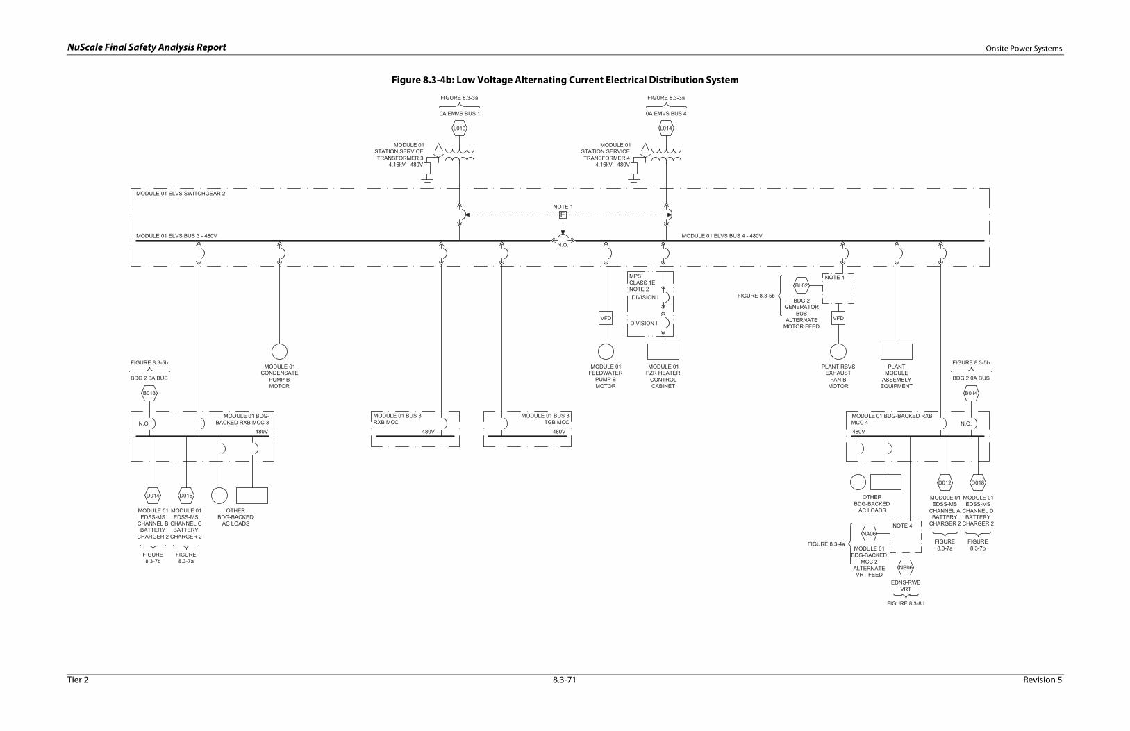
NuScale Final Safety Analysis Report Onsite Power Systems
Figure 8.3-4b: Low Voltage Alternating Current Electrical Distribution System
Tier 2 8.3-71 Revision 5

NuScale Final Safety Analysis Report Onsite Power Systems
Figure 8.3-4c: Low Voltage Alternating Current Electrical Distribution System
Tier 2 8.3-72 Revision 5
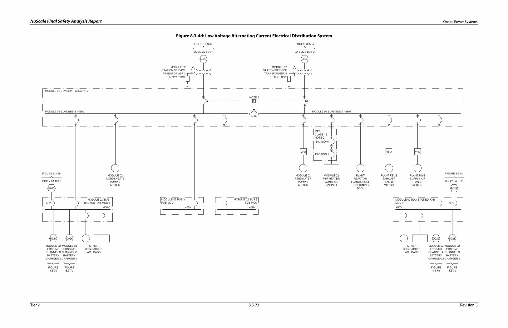
NuScale Final Safety Analysis Report Onsite Power Systems
Figure 8.3-4d: Low Voltage Alternating Current Electrical Distribution System
Tier 2 8.3-73 Revision 5

NuScale Final Safety Analysis Report Onsite Power Systems
Figure 8.3-4e: Low Voltage Alternating Current Electrical Distribution System
Tier 2 8.3-74 Revision 5

NuScale Final Safety Analysis Report Onsite Power Systems
Figure 8.3-4f: Low Voltage Alternating Current Electrical Distribution System
Tier 2 8.3-75 Revision 5

NuScale Final Safety Analysis Report Onsite Power Systems
Figure 8.3-4g: Low Voltage Alternating Current Electrical Distribution System
Tier 2 8.3-76 Revision 5

NuScale Final Safety Analysis Report Onsite Power Systems
Figure 8.3-4h: Low Voltage Alternating Current Electrical Distribution System
Tier 2 8.3-77 Revision 5

NuScale Final Safety Analysis Report Onsite Power Systems
Figure 8.3-4i: Low Voltage Alternating Current Electrical Distribution System
Tier 2 8.3-78 Revision 5

NuScale Final Safety Analysis Report Onsite Power Systems
Figure 8.3-4j: Low Voltage Alternating Current Electrical Distribution System
Tier 2 8.3-79 Revision 5

NuScale Final Safety Analysis Report Onsite Power Systems
Figure 8.3-4k: Low Voltage Alternating Current Electrical Distribution System
Tier 2 8.3-80 Revision 5

NuScale Final Safety Analysis Report Onsite Power Systems
Figure 8.3-4l: Low Voltage Alternating Current Electrical Distribution System
Tier 2 8.3-81 Revision 5

NuScale Final Safety Analysis Report Onsite Power Systems
Figure 8.3-4m: Low Voltage Alternating Current Electrical Distribution System
Tier 2 8.3-82 Revision 5
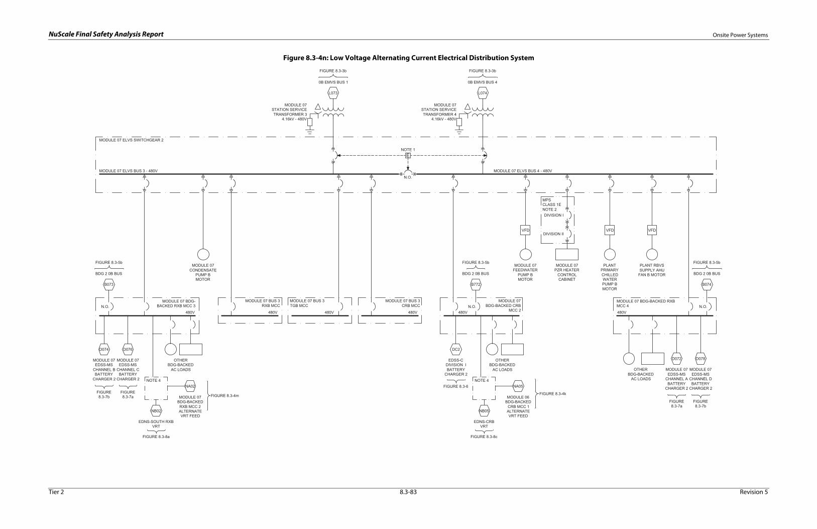
NuScale Final Safety Analysis Report Onsite Power Systems
Figure 8.3-4n: Low Voltage Alternating Current Electrical Distribution System
Tier 2 8.3-83 Revision 5

NuScale Final Safety Analysis Report Onsite Power Systems
Figure 8.3-4o: Low Voltage Alternating Current Electrical Distribution System
Tier 2 8.3-84 Revision 5

NuScale Final Safety Analysis Report Onsite Power Systems
Figure 8.3-4p: Low Voltage Alternating Current Electrical Distribution System
Tier 2 8.3-85 Revision 5

NuScale Final Safety Analysis Report Onsite Power Systems
Figure 8.3-4q: Low Voltage Alternating Current Electrical Distribution System
Tier 2 8.3-86 Revision 5

NuScale Final Safety Analysis Report Onsite Power Systems
Figure 8.3-4r: Low Voltage Alternating Current Electrical Distribution System
Tier 2 8.3-87 Revision 5
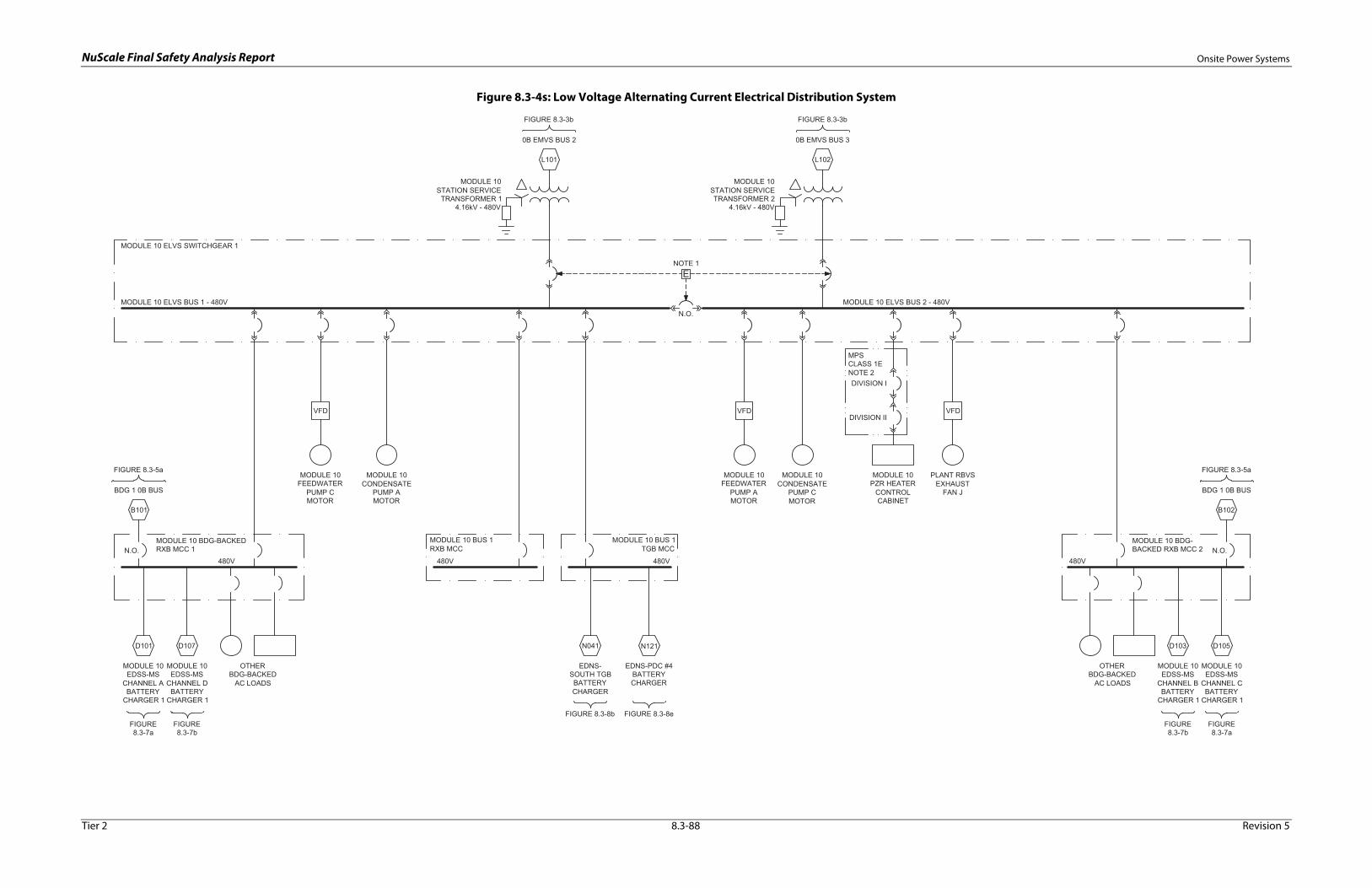
NuScale Final Safety Analysis Report Onsite Power Systems
Figure 8.3-4s: Low Voltage Alternating Current Electrical Distribution System
Tier 2 8.3-88 Revision 5
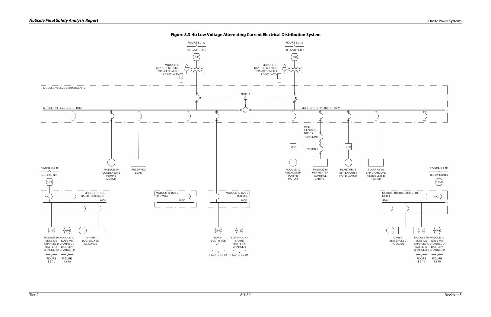
NuScale Final Safety Analysis Report Onsite Power Systems
Figure 8.3-4t: Low Voltage Alternating Current Electrical Distribution System
Tier 2 8.3-89 Revision 5

NuScale Final Safety Analysis Report Onsite Power Systems
Figure 8.3-4u: Low Voltage Alternating Current Electrical Distribution System
Tier 2 8.3-90 Revision 5

NuScale Final Safety Analysis Report Onsite Power Systems
Figure 8.3-4v: Low Voltage Alternating Current Electrical Distribution System
Tier 2 8.3-91 Revision 5

NuScale Final Safety Analysis Report Onsite Power Systems
Figure 8.3-4w: Low Voltage Alternating Current Electrical Distribution System
Tier 2 8.3-92 Revision 5

NuScale Final Safety Analysis Report Onsite Power Systems
Figure 8.3-4x: Low Voltage Alternating Current Electrical Distribution System
Tier 2 8.3-93 Revision 5
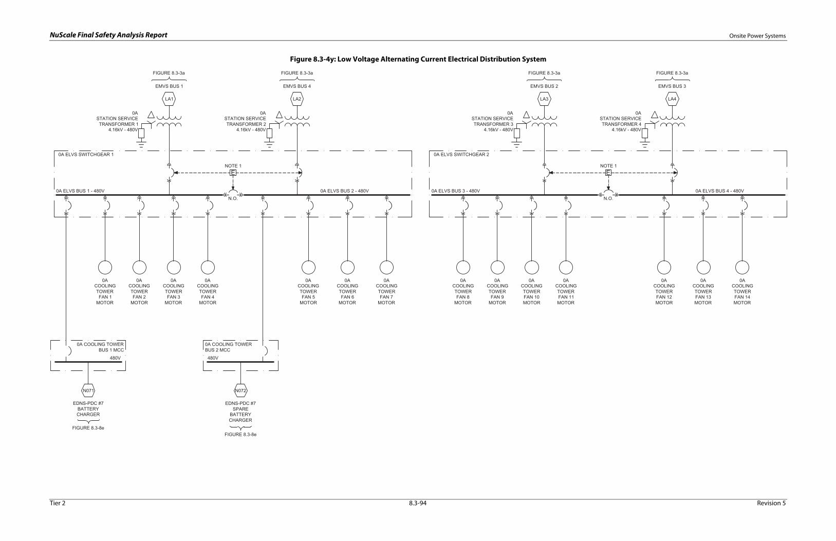
NuScale Final Safety Analysis Report Onsite Power Systems
Figure 8.3-4y: Low Voltage Alternating Current Electrical Distribution System
Tier 2 8.3-94 Revision 5

NuScale Final Safety Analysis Report Onsite Power Systems
Figure 8.3-4z: Low Voltage Alternating Current Electrical Distribution System
Tier 2 8.3-95 Revision 5
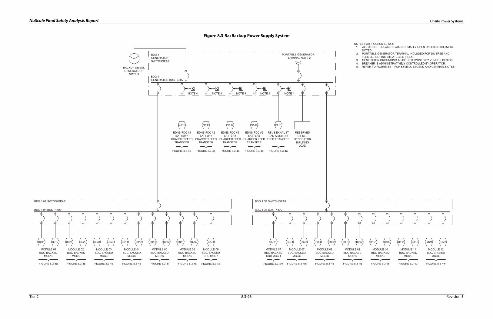
NuScale Final Safety Analysis Report Onsite Power Systems
Figure 8.3-5a: Backup Power Supply System
Tier 2 8.3-96 Revision 5

NuScale Final Safety Analysis Report Onsite Power Systems
Figure 8.3-5b: Backup Power Supply System
Tier 2 8.3-97 Revision 5
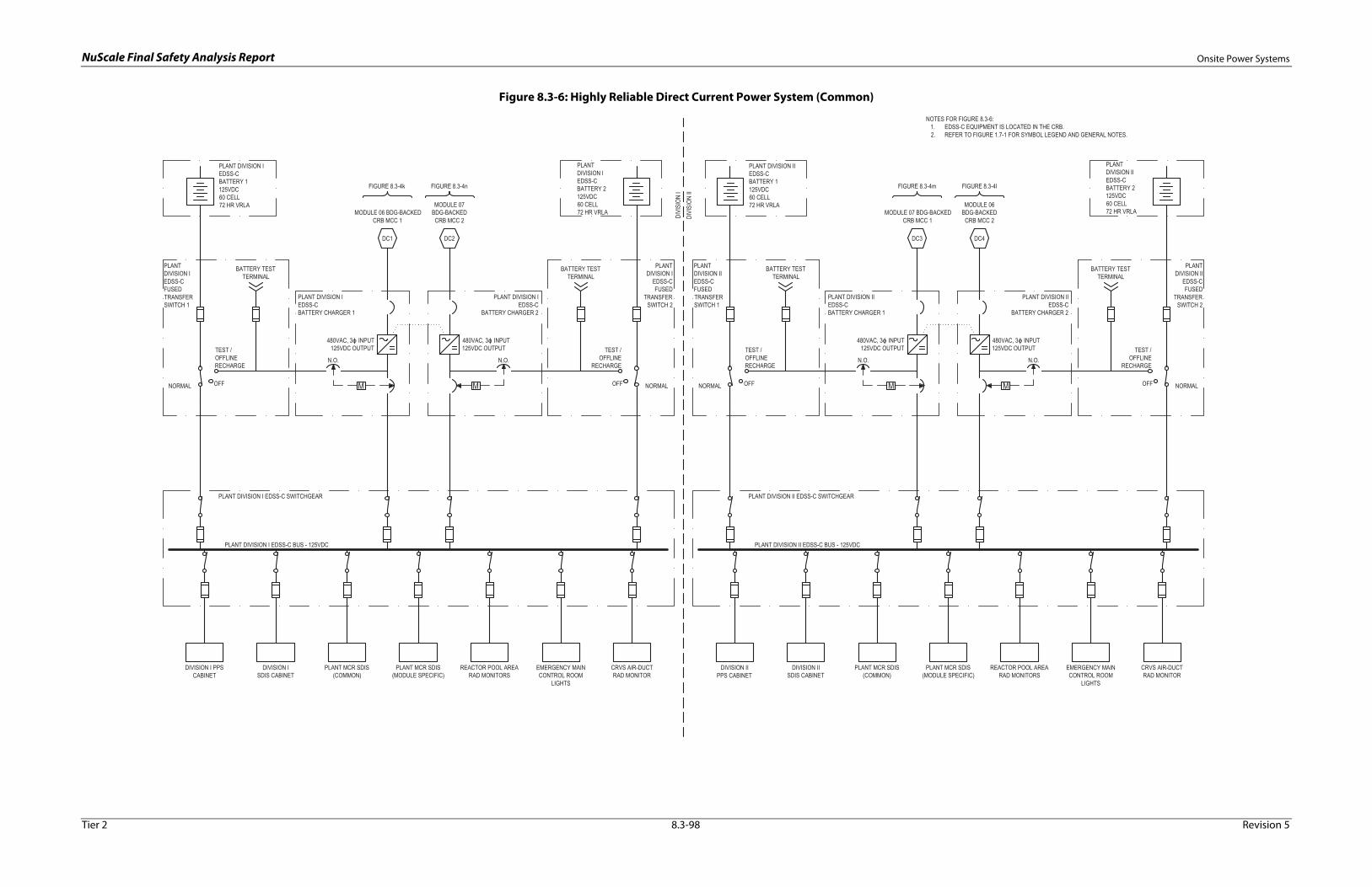
NuScale Final Safety Analysis Report Onsite Power Systems
Figure 8.3-6: Highly Reliable Direct Current Power System (Common)
PLANT DIVISION IEDSS-CBATTERY 1125VDC60 CELL72 HR VRLA
PLANT DIVISION IEDSS-CBATTERY CHARGER 1
BATTERY TESTTERMINAL
OFF
TEST /OFFLINERECHARGE
NORMAL
PLANTDIVISION IEDSS-CFUSEDTRANSFERSWITCH 1
PLANT DIVISION I EDSS-C BUS - 125VDC
PLANTDIVISION IEDSS-CBATTERY 2125VDC60 CELL72 HR VRLA
N.O. N.O.
MODULE 06 BDG-BACKEDCRB MCC 1
480VAC, 3 INPUT125VDC OUTPUT
480VAC, 3 INPUT125VDC OUTPUT
PLANT DIVISION IEDSS-C
BATTERY CHARGER 2
NOTES FOR FIGURE 8.3-6:1. EDSS-C EQUIPMENT IS LOCATED IN THE CRB.2. REFER TO FIGURE 1.7-1 FOR SYMBOL LEGEND AND GENERAL NOTES.
BATTERY TESTTERMINAL
OFF
TEST /OFFLINE
RECHARGE
NORMAL
PLANTDIVISION I
EDSS-CFUSED
TRANSFERSWITCH 2
DIVISION I PPSCABINET
DIVISION ISDIS CABINET
PLANT MCR SDIS(COMMON)
REACTOR POOL AREARAD MONITORS
EMERGENCY MAINCONTROL ROOM
LIGHTS
PLANT DIVISION IIEDSS-CBATTERY 1125VDC60 CELL72 HR VRLA
PLANT DIVISION IIEDSS-CBATTERY CHARGER 1
BATTERY TESTTERMINAL
OFF
TEST /OFFLINERECHARGE
NORMAL
PLANTDIVISION IIEDSS-CFUSEDTRANSFERSWITCH 1
PLANTDIVISION IIEDSS-CBATTERY 2125VDC60 CELL72 HR VRLA
N.O. N.O.
480VAC, 3 INPUT125VDC OUTPUT
480VAC, 3 INPUT125VDC OUTPUT
PLANT DIVISION IIEDSS-C
BATTERY CHARGER 2
BATTERY TESTTERMINAL
OFF
TEST /OFFLINE
RECHARGE
NORMAL
PLANTDIVISION II
EDSS-CFUSED
TRANSFERSWITCH 2
DIVI
SION
IDI
VISI
ON II
PLANT DIVISION I EDSS-C SWITCHGEAR
PLANT DIVISION II EDSS-C BUS - 125VDC
PLANT DIVISION II EDSS-C SWITCHGEAR
PLANT MCR SDIS(MODULE SPECIFIC)
MODULE 07BDG-BACKED
CRB MCC 2
CRVS AIR-DUCTRAD MONITOR
DIVISION IIPPS CABINET
DIVISION IISDIS CABINET
PLANT MCR SDIS(COMMON)
REACTOR POOL AREARAD MONITORS
EMERGENCY MAINCONTROL ROOM
LIGHTS
PLANT MCR SDIS(MODULE SPECIFIC)
CRVS AIR-DUCTRAD MONITOR
DC1 DC2 DC3 DC4
MODULE 07 BDG-BACKEDCRB MCC 1
MODULE 06BDG-BACKED
CRB MCC 2
FIGURE 8.3-4k FIGURE 8.3-4n FIGURE 8.3-4m FIGURE 8.3-4l
Tier 2 8.3-98 Revision 5
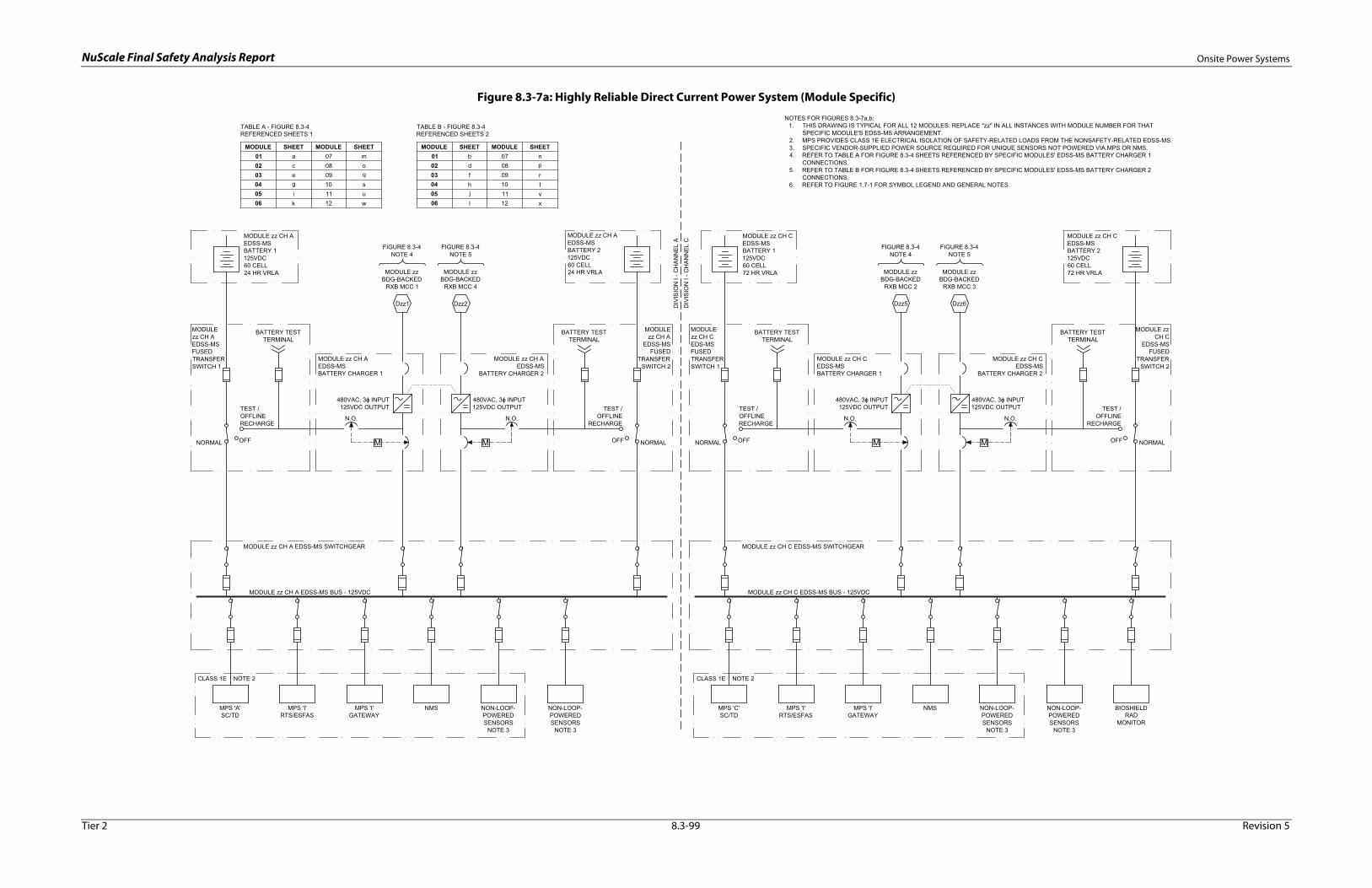
NuScale Final Safety Analysis Report Onsite Power Systems
Figure 8.3-7a: Highly Reliable Direct Current Power System (Module Specific)
NOTES FOR FIGURES 8.3-7a,b:1. THIS DRAWING IS TYPICAL FOR ALL 12 MODULES: REPLACE "zz" IN ALL INSTANCES WITH MODULE NUMBER FOR THAT
SPECIFIC MODULE'S EDSS-MS ARRANGEMENT.2. MPS PROVIDES CLASS 1E ELECTRICAL ISOLATION OF SAFETY-RELATED LOADS FROM THE NONSAFETY-RELATED EDSS-MS.3. SPECIFIC VENDOR-SUPPLIED POWER SOURCE REQUIRED FOR UNIQUE SENSORS NOT POWERED VIA MPS OR NMS.4. REFER TO TABLE A FOR FIGURE 8.3-4 SHEETS REFERENCED BY SPECIFIC MODULES' EDSS-MS BATTERY CHARGER 1
CONNECTIONS.5. REFER TO TABLE B FOR FIGURE 8.3-4 SHEETS REFERENCED BY SPECIFIC MODULES' EDSS-MS BATTERY CHARGER 2
CONNECTIONS.6. REFER TO FIGURE 1.7-1 FOR SYMBOL LEGEND AND GENERAL NOTES.
M M
MODULE zz CH AEDSS-MSBATTERY 1125VDC60 CELL24 HR VRLA
MODULE zz CH AEDSS-MSBATTERY CHARGER 1
BATTERY TESTTERMINAL
OFF
TEST /OFFLINERECHARGE
NORMAL
MODULEzz CH AEDSS-MSFUSEDTRANSFERSWITCH 1
MODULE zz CH AEDSS-MSBATTERY 2125VDC60 CELL24 HR VRLA
N.O. N.O.
FIGURE 8.3-4NOTE 4
FIGURE 8.3-4NOTE 5
MODULE zzBDG-BACKED
RXB MCC 1
MODULE zzBDG-BACKED
RXB MCC 4
480VAC, 3 INPUT125VDC OUTPUT
480VAC, 3 INPUT125VDC OUTPUT
MODULE zz CH AEDSS-MS
BATTERY CHARGER 2
BATTERY TESTTERMINAL
OFF
TEST /OFFLINE
RECHARGE
NORMAL
MODULEzz CH A
EDSS-MSFUSED
TRANSFERSWITCH 2
MPS 'A'SC/TD
MPS 'I'RTS/ESFAS
MPS 'I'GATEWAY
Dzz1 Dzz2
M M
MODULE zz CH CEDSS-MSBATTERY 1125VDC60 CELL72 HR VRLA
MODULE zz CH CEDSS-MSBATTERY CHARGER 1
BATTERY TESTTERMINAL
OFF
TEST /OFFLINERECHARGE
NORMAL
MODULEzz CH CEDS-MSFUSEDTRANSFERSWITCH 1
MODULE zz CH CEDSS-MSBATTERY 2125VDC60 CELL72 HR VRLA
N.O. N.O.
FIGURE 8.3-4NOTE 4
FIGURE 8.3-4NOTE 5
MODULE zzBDG-BACKED
RXB MCC 2
MODULE zzBDG-BACKED
RXB MCC 3
480VAC, 3 INPUT125VDC OUTPUT
480VAC, 3 INPUT125VDC OUTPUT
MODULE zz CH CEDSS-MS
BATTERY CHARGER 2
BATTERY TESTTERMINAL
OFF
TEST /OFFLINE
RECHARGE
NORMAL
MODULE zzCH C
EDSS-MSFUSED
TRANSFERSWITCH 2
Dzz5 Dzz6DIV
ISIO
N I
- CH
AN
NE
L A
DIV
ISIO
N I
- CH
AN
NE
L C
MODULE zz CH C EDSS-MS BUS - 125VDC
MODULE zz CH C EDSS-MS SWITCHGEAR
MODULE zz CH A EDSS-MS BUS - 125VDC
MODULE zz CH A EDSS-MS SWITCHGEAR
CLASS 1E NOTE 2
NMS MPS 'C'SC/TD
MPS 'I'RTS/ESFAS
MPS 'I'GATEWAY
CLASS 1E NOTE 2
NMS BIOSHIELDRAD
MONITOR
NON-LOOP-POWEREDSENSORS
NOTE 3
NON-LOOP-POWEREDSENSORS
NOTE 3
NON-LOOP-POWEREDSENSORS
NOTE 3
NON-LOOP-POWEREDSENSORS
NOTE 3
MODULE SHEET MODULE SHEET01 a 07 m02 c 08 o03 e 09 q04 g 10 s05 i 11 u06 k 12 w
TABLE A - FIGURE 8.3-4REFERENCED SHEETS 1
MODULE SHEET MODULE SHEET01 b 07 n02 d 08 p03 f 09 r04 h 10 t05 j 11 v06 l 12 x
TABLE B - FIGURE 8.3-4REFERENCED SHEETS 2
Tier 2 8.3-99 Revision 5
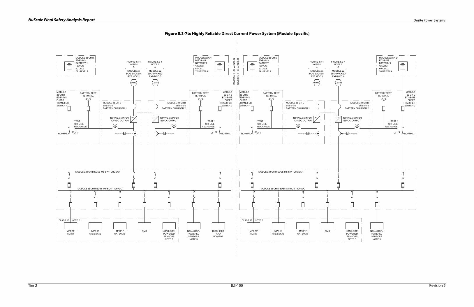
NuScale Final Safety Analysis Report Onsite Power Systems
Figure 8.3-7b: Highly Reliable Direct Current Power System (Module Specific)
M M
MODULE zz CH BEDSS-MSBATTERY 1125VDC60 CELL72 HR VRLA
MODULE zz CH BEDSS-MSBATTERY CHARGER 1
BATTERY TESTTERMINAL
OFF
TEST /OFFLINERECHARGE
NORMAL
MODULEzz CH BEDSS-MSFUSEDTRANSFERSWITCH 1
MODULE zz CHB EDS-MSBATTERY 2125VDC60 CELL72 HR VRLA
N.O. N.O.
FIGURE 8.3-4NOTE 4
FIGURE 8.3-4NOTE 5
MODULE zzBDG-BACKED
RXB MCC 2
MODULE zzBDG-BACKED
RXB MCC 3
480VAC, 3 INPUT125VDC OUTPUT
480VAC, 3 INPUT125VDC OUTPUT
MODULE zz CH BEDSS-MS
BATTERY CHARGER 2
BATTERY TESTTERMINAL
OFF
TEST /OFFLINE
RECHARGE
NORMAL
MODULEzz CH B
EDSS-MSFUSED
TRANSFERSWITCH 2
Dzz3 Dzz4
M M
MODULE zz CH DEDSS-MSBATTERY 1125VDC60 CELL24 HR VRLA
MODULE zz CH DEDSS-MSBATTERY CHARGER 1
BATTERY TESTTERMINAL
OFF
TEST /OFFLINERECHARGE
NORMAL
MODULEzz CH DEDSS-MSFUSEDTRANSFERSWITCH 1
MODULE zz CH DEDSS-MSBATTERY 2125VDC60 CELL24 HR VRLA
N.O. N.O.
FIGURE 8.3-4NOTE 4
FIGURE 8.3-4NOTE 5
MODULE zzBDG-BACKED
RXB MCC 1
MODULE zzBDG-BACKED
RXB MCC 4
480VAC, 3 INPUT125VDC OUTPUT
480VAC, 3 INPUT125VDC OUTPUT
MODULE zz CH DEDSS-MS
BATTERY CHARGER 2
BATTERY TESTTERMINAL
OFF
TEST /OFFLINE
RECHARGE
NORMAL
MODULEzz CH D
EDSS-MSFUSED
TRANSFERSWITCH 2
Dzz7 Dzz8DIV
ISIO
N II
- C
HA
NN
EL
B
DIV
ISIO
N II
- C
HA
NN
EL
D
MODULE zz CH B EDSS-MS BUS - 125VDC
MODULE zz CH B EDSS-MS SWITCHGEAR
MODULE zz CH D EDSS-MS BUS - 125VDC
MODULE zz CH D EDSS-MS SWITCHGEAR
MPS 'D'SC/TD
MPS 'II'RTS/ESFAS
MPS 'II'GATEWAY
CLASS 1E NOTE 2
NMSMPS 'B'SC/TD
MPS 'II'RTS/ESFAS
MPS 'II'GATEWAY
CLASS 1E NOTE 2
NMS NON-LOOP-POWEREDSENSORS
NOTE 3
NON-LOOP-POWEREDSENSORS
NOTE 3
BIOSHIELDRAD
MONITOR
NON-LOOP-POWEREDSENSORS
NOTE 3
NON-LOOP-POWEREDSENSORS
NOTE 3
Tier 2 8.3-100 Revision 5

NuScale Final Safety Analysis Report Onsite Power Systems
Figure 8.3-8a: Normal Direct Current Power System
NOTES FOR FIGURES 8.3-8a:1. MANUAL MAINTENANCE BYPASS SWITCH WITH OVERLAPPING CONTACTS PERMITS TRANSFERRING TO ALTERNATE SOURCE
WITHOUT INTERRUPTION OF POWER AND AT THE SAME TIME ISOLATES THE INVERTER.2. DELETED3. CLASS 1E CONTROL ROD DRIVE SYSTEM MAIN POWER BREAKERS ARE CONTROLLED BY THE MPS.4. ENTIRE DRAWING IS TYPICAL FOR THE ENDS-NORTH RXB AND ENDS-SOUTH RXB SUBSYSTEMS.5. REFER TO TABLE A FOR TABLE OF CONNECTIONS BETWEEN EDNS-RXB SUSYSTEMS AND ELVS.6. REFER TO FIGURE 1.7-1 FOR SYMBOL LEGEND AND GENERAL NOTES.
M
EDNS-RXBBATTERY250VDC120 CELL40 MIN VRLA
BATTERY TESTTERMINAL
OFF
TEST /OFFLINERECHARGE
NORMAL
N.O.
480VAC, 3 INPUT250VDC OUTPUT
MANUALMAINTENANCE/BYPASS
SWITCH (NOTE 1)
STATIC SWITCH
EDNS-RXBINVERTER 1
EDNS-RXBVOLTAGE REGULATINGTRANSFORMER
480V - 120/208VAC, 3
EDNS-RXB AC BUS - 120/208VAC, 3
EDNS-RXB AC SWITCHGEAR
EDNS-RXB BATTERY BACKED AC LOADS
EDNS-RXBBATTERY CHARGER
N.O.
SPARE BATTERY/CHARGER TERMINAL
EDNS-RXBFUSED TRANSFERSWITCH
EDNS-RXB DC SWITCHGEAR
EDNS-RXB DC BUS - 250VDC
MANUALMAINTENANCE/BYPASSSWITCH (NOTE 1)
STATIC SWITCH
250VDC INPUT120/208VAC, 3 OUTPUT
250VDC INPUT120/208VAC, 3 OUTPUT
EDNS-RXBINVERTER 2
ELV CONNECTIONNOTE 5
FIGURE 8.3-4
ELV CONNECTIONNOTE 5
FIGURE 8.3-4
MPS CLASS 1ENOTE 3
DIVISION I DIVISION II
CRDS MAINPOWER
TABLE A - EDNS RXBCONNECTIONS
EDNS-RXB NORTHEDNS-RXB SOUTH
N011N021
km
NB01NB02
ID SHEET IDln
SHEET
Tier 2 8.3-101 Revision 5
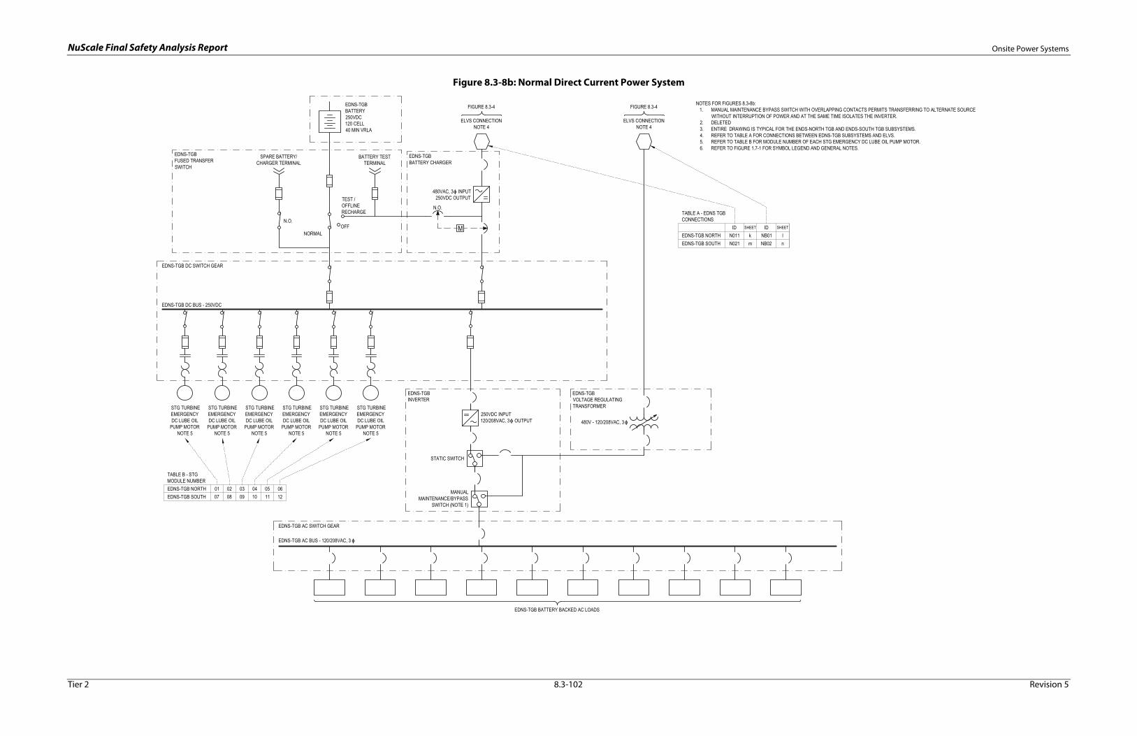
NuScale Final Safety Analysis Report Onsite Power Systems
Figure 8.3-8b: Normal Direct Current Power System
M
EDNS-TGBBATTERY250VDC120 CELL40 MIN VRLA
BATTERY TESTTERMINAL
OFF
TEST /OFFLINERECHARGE
NORMAL
N.O.
480VAC, 3 INPUT250VDC OUTPUT
MANUALMAINTENANCE/BYPASS
SWITCH (NOTE 1)
STATIC SWITCH
250VDC INPUT120/208VAC, 3 OUTPUT
EDNS-TGBINVERTER
EDNS-TGBVOLTAGE REGULATINGTRANSFORMER
480V - 120/208VAC, 3
EDNS-TGB DC BUS - 250VDC
EDNS-TGBFUSED TRANSFERSWITCH
EDNS-TGB AC BUS - 120/208VAC, 3
EDNS-TGB AC SWITCH GEAR
EDNS-TGB DC SWITCH GEAR
EDNS-TGB BATTERY BACKED AC LOADS
EDNS-TGBBATTERY CHARGER
STG TURBINEEMERGENCYDC LUBE OIL
PUMP MOTORNOTE 5
STG TURBINEEMERGENCYDC LUBE OIL
PUMP MOTORNOTE 5
N.O.
SPARE BATTERY/CHARGER TERMINAL
FIGURE 8.3-4
ELVS CONNECTIONNOTE 4
ELVS CONNECTIONNOTE 4
FIGURE 8.3-4 NOTES FOR FIGURES 8.3-8b:1. MANUAL MAINTENANCE BYPASS SWITCH WITH OVERLAPPING CONTACTS PERMITS TRANSFERRING TO ALTERNATE SOURCE
WITHOUT INTERRUPTION OF POWER AND AT THE SAME TIME ISOLATES THE INVERTER.2. DELETED3. ENTIRE DRAWING IS TYPICAL FOR THE ENDS-NORTH TGB AND ENDS-SOUTH TGB SUBSYSTEMS.4. REFER TO TABLE A FOR CONNECTIONS BETWEEN EDNS-TGB SUBSYSTEMS AND ELVS.5. REFER TO TABLE B FOR MODULE NUMBER OF EACH STG EMERGENCY DC LUBE OIL PUMP MOTOR.6. REFER TO FIGURE 1.7-1 FOR SYMBOL LEGEND AND GENERAL NOTES.
TABLE A - EDNS TGBCONNECTIONS
EDNS-TGB NORTHEDNS-TGB SOUTH
N011N021
km
NB01NB02
ID SHEET IDln
SHEET
STG TURBINEEMERGENCYDC LUBE OIL
PUMP MOTORNOTE 5
STG TURBINEEMERGENCYDC LUBE OIL
PUMP MOTORNOTE 5
STG TURBINEEMERGENCYDC LUBE OIL
PUMP MOTORNOTE 5
STG TURBINEEMERGENCYDC LUBE OIL
PUMP MOTORNOTE 5
TABLE B - STGMODULE NUMBEREDNS-TGB NORTHEDNS-TGB SOUTH
0107
0208
0309
0410
0511
0612
Tier 2 8.3-102 Revision 5
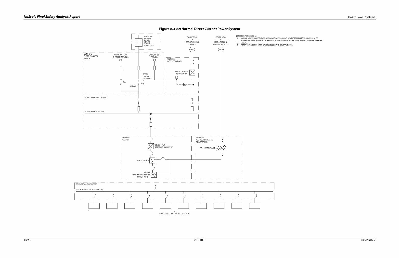
NuScale Final Safety Analysis Report Onsite Power Systems
Figure 8.3-8c: Normal Direct Current Power System
M
EDNS-CRBBATTERY125VDC60 CELL40 MIN VRLA
BATTERY TESTTERMINAL
OFF
TEST /OFFLINERECHARGE
NORMAL
N.O.
480VAC, 3 INPUT125VDC OUTPUT
MANUALMAINTENANCE/BYPASS
SWITCH (NOTE 1)
STATIC SWITCH
EDNS-CRBINVERTER
EDNS-CRBVOLTAGE REGULATINGTRANSFORMER
480V - 120/208VAC, 3
EDNS-CRB AC BUS - 120/208VAC, 3
EDNS-CRB BATTERY BACKED AC LOADS
EDNS-CRBBATTERY CHARGER
N.O.
SPARE BATTERY/CHARGER TERMINAL
EDNS-CRBFUSED TRANSFERSWITCH
EDNS-CRB DC SWITCHGEAR
EDNS-CRB DC BUS - 125VDC
125VDC INPUT120/208VAC, 3 OUTPUT 480V - 120/208VAC, 3
EDNS-CRB AC SWITCHGEAR
FIGURE 8.3-4k FIGURE 8.3-4n
N051
MODULE 07 BDG-BACKED CRB MCC 2
NB05
MODULE 06 BUS 1CRB MCC
NOTES FOR FIGURES 8.3-8c:1. MANUAL MAINTENANCE BYPASS SWITCH WITH OVERLAPPING CONTACTS PERMITS TRANSFERRING TO
ALTERNATE SOURCE WITHOUT INTERRUPTION OF POWER AND AT THE SAME TIME ISOLATES THE INVERTER.2. DELETED3. REFER TO FIGURE 1.7-1 FOR SYMBOL LEGEND AND GENERAL NOTES.
Tier 2 8.3-103 Revision 5

NuScale Final Safety Analysis Report Onsite Power Systems
Figure 8.3-8d: Normal Direct Current Power System
M
EDNS-RWBBATTERY125VDC60 CELL40 MIN VRLA
BATTERY TESTTERMINAL
OFF
TEST /OFFLINERECHARGE
NORMAL
N.O.
480VAC, 3 INPUT125VDC OUTPUT
MANUALMAINTENANCE/BYPASS
SWITCH (NOTE 1)
STATIC SWITCH
EDNS-RWBINVERTER
EDNS-RWBVOLTAGE REGULATINGTRANSFORMER
480V - 120/208VAC, 3
EDNS-RWB AC BUS - 120/208VAC, 3
EDNS-RWB BATTERY BACKED AC LOADS
EDNS-RWBBATTERY CHARGER
N.O.
SPARE BATTERY/CHARGER TERMINAL
EDNS-RWBFUSED TRANSFERSWITCH
EDNS-RWB DC SWITCHGEAR
EDNS-CRB DC BUS - 125VDC
125VDC INPUT120/208VAC, 3 OUTPUT 480V - 120/208VAC, 3
EDNS-RWB AC SWITCHGEAR
FIGURE 8.3-4u FIGURE 8.3-4b
N061
MODULE 01 BDG-BACKED RXB MCC 4
NB06
MODULE 11 BUS 1RWB MCC
NOTES FOR FIGURES 8.3-8d:1. MANUAL MAINTENANCE BYPASS SWITCH WITH OVERLAPPING CONTACTS PERMITS TRANSFERRING TO
ALTERNATE SOURCE WITHOUT INTERRUPTION OF POWER AND AT THE SAME TIME ISOLATES THE INVERTER.2. DELETED3. REFER TO FIGURE 1.7-1 FOR SYMBOL LEGEND AND GENERAL NOTES.
Tier 2 8.3-104 Revision 5
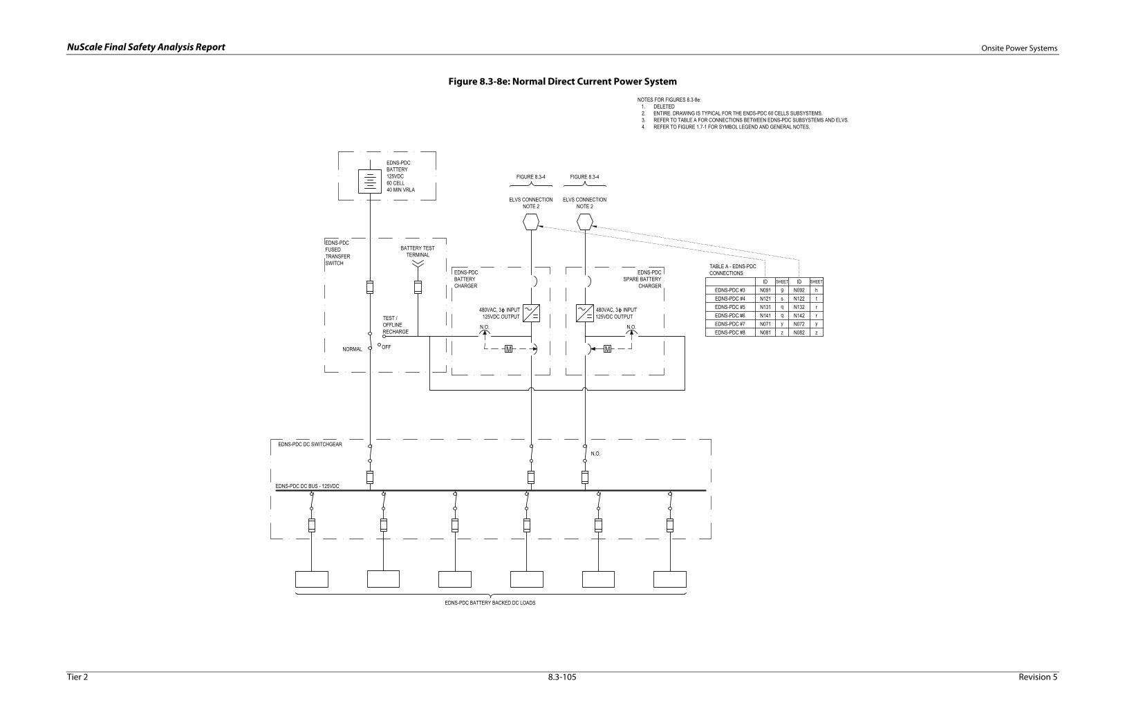
NuScale Final Safety Analysis Report Onsite Power Systems
Figure 8.3-8e: Normal Direct Current Power System
M M
EDNS-PDCBATTERY125VDC60 CELL40 MIN VRLA
EDNS-PDCBATTERYCHARGER
BATTERY TESTTERMINAL
OFF
TEST /OFFLINERECHARGE
NORMAL
EDNS-PDCFUSEDTRANSFERSWITCH
EDNS-PDC DC BUS - 125VDC
N.O. N.O.
480VAC, 3 INPUT125VDC OUTPUT
480VAC, 3 INPUT125VDC OUTPUT
EDNS-PDCSPARE BATTERY
CHARGER
EDNS-PDC DC SWITCHGEAR
EDNS-PDC BATTERY BACKED DC LOADS
N.O.
FIGURE 8.3-4 FIGURE 8.3-4
ELVS CONNECTIONNOTE 2
ELVS CONNECTIONNOTE 2
NOTES FOR FIGURES 8.3-8e:1. DELETED2. ENTIRE DRAWING IS TYPICAL FOR THE ENDS-PDC 60 CELLS SUBSYSTEMS.3. REFER TO TABLE A FOR CONNECTIONS BETWEEN EDNS-PDC SUBSYSTEMS AND ELVS.4. REFER TO FIGURE 1.7-1 FOR SYMBOL LEGEND AND GENERAL NOTES.
TABLE A - EDNS-PDCCONNECTIONS
EDNS-PDC #3EDNS-PDC #4
N091N121
gs
N092N122
ID SHEET IDht
SHEET
EDNS-PDC #5 N131 q N132 rEDNS-PDC #6 N141 q N142 rEDNS-PDC #7 N071 y N072 yEDNS-PDC #8 N081 z N082 z
Tier 2 8.3-105 Revision 5

NuScale Final Safety Analysis Report Onsite Power Systems
Figure 8.3-8f: Normal Direct Current Power System
M M
EDNS-PDC #1BATTERY125VDC120 CELL40 MIN VRLA
EDNS-PDC #1BATTERYCHARGER
BATTERY TESTTERMINAL
OFF
TEST /OFFLINERECHARGE
NORMAL
EDNS-PDC #1FUSEDTRANSFERSWITCH
EDNS-PDC #1 DC BUS - 125VDC
N.O. N.O.
480VAC, 3 INPUT125VDC OUTPUT
480VAC, 3 INPUT125VDC OUTPUT
EDNS-PDC #1SPARE BATTERY
CHARGER
EDNS-PDC #1 DC SWITCHGEAR
EDNS-PDC 120 CELL BATTERY BACKED DC LOADS
N.O.
FIGURE 8.3-4e FIGURE 8.3-4f
N101
MODULE 03 BUS 1 TGBMCC
N102
MODULE 03 BUS 3 TGBMCC
NOTES FOR FIGURES 8.3-8f:1. DELETED2. ENTIRE DRAWING IS TYPICAL FOR THE ENDS-PDC 120 CELL SUBSYSTEMS.3. REFER TO TABLE A FOR CONNECTIONS BETWEEN EDNS-PDC 120 CELL SUBSYSTEMS AND ELVS.4. REFER TO FIGURE 1.7-1 FOR SYMBOL LEGEND AND GENERAL NOTES.
TABLE A - EDNS-PDCCONNECTIONS
EDNS-PDC #1EDNS-PDC #2
N101N111
eg
N102N112
ID SHEET IDfh
SHEET
Tier 2 8.3-106 Revision 5

NuScale Final Safety Analysis Report Station Blackout
8.4 Station Blackout
A station blackout (SBO) is a complete loss of offsite and onsite alternating current (AC) power concurrent with a turbine trip and the unavailability of onsite emergency AC power. The SBO rule, 10 CFR 50.63, requires each plant to demonstrate sufficient capacity and capability to ensure that the reactor core is cooled and appropriate containment integrity is maintained in the event of an SBO for the specified duration. As described in Section 8.3, the NuScale Power Module (NPM) design does not rely on the use of onsite or offsite AC power for the performance of safety-related functions during a design basis event. As a result, emergency onsite AC power is not included in the design.
The SBO duration for passive plant designs is 72 hours, which is consistent with Nuclear Regulatory Commission policy provided by SECY-94-084 and SECY-95-132 and the associated staff requirements memorandums. Passive plants are required to demonstrate that safety-related functions can be performed without reliance on AC power for 72 hours after the initiating event. The relevant guidelines of Regulatory Guide (RG) 1.155 are applied as they pertain to compliance with 10 CFR 50.63 for the passive NuScale design.
8.4.1 Station Blackout Analysis Assumptions
The analysis of the SBO transient response includes the following assumptions:
• A total of 12 NPMs and supporting equipment are initially operating normally at a minimum of 100 percent rated thermal power for 100 days.
• At time zero, an SBO occurs as a result of a complete loss of onsite and offsite AC power.
• The 12 NPM turbine generators trip as a result of the loss of AC power.
• Power from the highly reliable DC power system (EDSS) is available.
• No credit is taken for manual operator actions.
• No additional single failures occur.
• The event duration is 72 hours.
8.4.2 Station Blackout Analysis and Results
The SBO does not pose a significant challenge to the advanced passive design of the NuScale Power Plant, which does not rely on AC power for performing safety functions. A safe and stable shutdown is automatically achieved and maintained for 72 hours without operator actions. The SBO transient analysis demonstrates that the acceptance criteria of 10 CFR 50.63 are met.
Tier 2 8.4-1 Revision 5
The SBO transient analysis employs the NRELAP5 code to model the NPM response to an SBO event for the required 72-hour duration. The NRELAP5 model, which is described in Section 15.0, is qualified to predict the plant response to the SBO. The core decay heat model is based on an infinite operating time at an initial power of 100 percent, and the analysis conservatively accounts for the combined heat input from a total of 12 NPMs and the spent fuel pool on the reactor pool response.

NuScale Final Safety Analysis Report Station Blackout
The SBO sequence of events is provided in Table 8.4-1. The SBO transient results in a turbine trip and a loss of feedwater flow. The resulting primary side pressure increase results in a module protection system (MPS) reactor trip signal on high pressurizer pressure, a decay heat removal system (DHRS) actuation, and a single cycle of a reactor safety valve (RSV). Within 65 seconds, the MPS initiates automatic containment isolation on a low AC voltage to battery charger signal. The containment isolation includes the chemical and volume control system valves, which prevents inventory loss due to letdown.
Within one minute, the DHRS begins to transfer heat from the reactor to the reactor pool and continues to operate for the event duration. After 24 hours, the MPS actuates the emergency core cooling system (ECCS), and the ECCS vent and recirculation valves automatically open. At this point, the pressure and water level in the reactor pressure vessel (RPV) decrease, and containment vessel (CNV) pressure rapidly increases until equilibrium is reached. The DHRS cooling then declines in favor of cooling through the CNV wall via reactor coolant that circulates through the CNV. Stable cooling continues to the end of the transient, with a continued slow decrease in the temperature and pressure in the RPV and CNV. The water level in the RPV remains stable at more than 9 feet above the top of the active fuel.
The analysis results show that a safe and stable shutdown is achieved, and that the reactor is cooled and containment integrity is maintained for the 72-hour duration without reliance on operator actions. The core remains subcritical for the duration of the event. The reactor coolant inventory ensures that the core remains covered without the need for makeup systems. The RPV water level is well above the top of active fuel as shown in Figure 8.4-1. After the reactor trips, the RPV pressure decreases rapidly and stabilizes at low pressures as shown in Figure 8.4-2. In addition, containment pressure and temperature are well below the design limits of 1000 psia and 550 degrees F as shown in Figure 8.4-3 and Figure 8.4-4.
8.4.3 Station Blackout Coping Equipment Assessment
The design adequacy and capability of equipment needed to cope with an SBO for the 72-hour duration of the event was evaluated, and the applicable guidance of Section C.3.2 of RG 1.155 was considered. The evaluation provides reasonable assurance that the required SBO equipment remains operable, and that special equipment provisions or operator actions are not necessary to ensure the operability of SBO mitigation equipment for the 72-hour duration. Nonsafety-related equipment is not relied upon to mitigate an SBO, and there is no SBO mitigation equipment that requires regulatory oversight under the regulatory treatment of nonsafety systems process, which is described in Section 8.1.4.3 and Section 19.3.
Tier 2 8.4-2 Revision 5
Consistent with the 10 CFR 50.2 definition of an SBO, the SBO transient analysis assumes a complete loss of AC power and that the EDSS remains operable during the transient. The EDSS batteries have sufficient capacity to provide power to post-accident monitoring and main control room emergency lighting loads for the 72-hour duration without charging. The EDSS design description, which includes testing and design criteria, is provided in Section 8.3.2.
Although not required to meet the requirements of 10 CFR 50.63, an SBO transient sensitivity case that considered a simultaneous complete loss of AC and DC power was also

NuScale Final Safety Analysis Report Station Blackout
evaluated. In the sensitivity case, the timing for the DHRS and the ECCS actuations change, however, the results show that the SBO acceptance criteria for reactor core cooling and containment integrity are met under conditions that exceed those required to demonstrate compliance with the rule.
The environmental conditions in the main control room during the SBO were evaluated. The control room remains habitable for the duration of the SBO event using the control room habitability system. The control room instrumentation to monitor the event mitigation and confirm the status of reactor cooling, reactor integrity, and containment integrity also remains available. The control room habitability system is described in Section 6.4.
Appropriate containment integrity is provided during the SBO event. The SBO transient analysis containment response demonstrates that the containment temperature and pressure are within design limits. The containment isolation valves automatically close following receipt of an MPS actuation signal. Containment isolation valve position indication is powered from the EDSS and is available for the operators to verify valve closure.
8.4.4 Station Blackout Procedures and Training
The SBO procedures and training consider the relevant guidance of RG 1.155 as it pertains to passive plants. Training and procedures to mitigate an SBO event are implemented in accordance with Section 13.2 and Section 13.5. The SBO mitigation procedures address SBO response (e.g. restoration of onsite standby power sources), AC power restoration (e.g. coordination with transmission system load dispatcher), and severe weather guidance (e.g. identification of site-specific actions to prepare for the onset of severe weather such as an impending tornado), as applicable. Restoration from an SBO event will be contingent upon AC power being made available from the offsite power system (if provided) or the backup power supply system, which are described in Section 8.2 and Section 8.3.
Tier 2 8.4-3 Revision 5

NuScale Final Safety Analysis Report Station Blackout
Table 8.4-1: Station Blackout Sequence of Events
Station Blackout Event Time (Seconds) ValueLoss of AC power 0High pressurizer pressure signal 9 2000 psiaRTS actuation signal 9RTS actuation 11Maximum primary pressure 16 2081 psiaDHRS valves fully open 41Maximum secondary pressure 52 1247 psiaContainment isolation signal 60Containment isolation 62ECCS actuation signal 86400ECCS actuation 86403Maximum containment temperature 86545 252 °FMaximum containment pressure 86648 36 psia
Tier 2 8.4-4 Revision 5
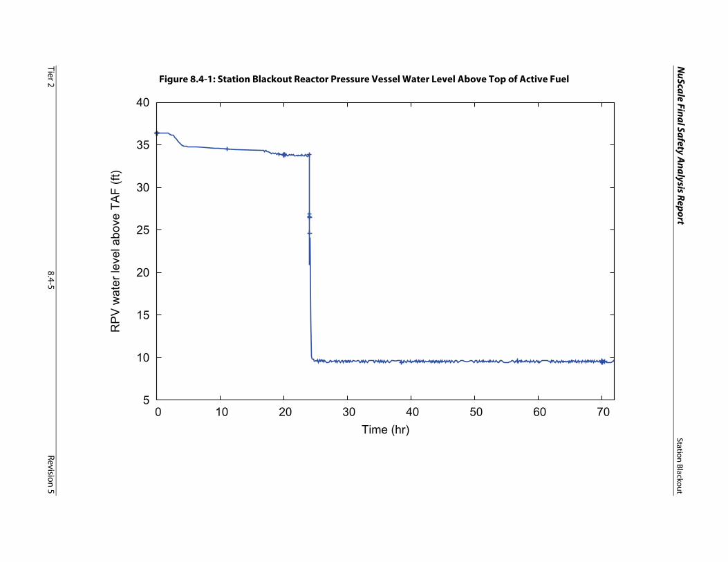
NuScale Final Safety A
nalysis ReportStation Blackout
Tier 28.4-5
Revision 5
Figure 8.4-1: Station Blackout Reactor Pressure Vessel Water Level Above Top of Active Fuel
5
10
15
20
25
30
35
40
0 10 20 30 40 50 60 70
RP
V w
ater
leve
l abo
ve T
AF
(ft)
Time (hr)

NuScale Final Safety A
nalysis ReportStation Blackout
Tier 28.4-6
Revision 5
Figure 8.4-2: Station Blackout Reactor Pressure Vessel Pressure
0
500
1000
1500
2000
2500
0 10 20 30 40 50 60 70
RP
V p
ress
ure
(psi
a)
Time (hr)
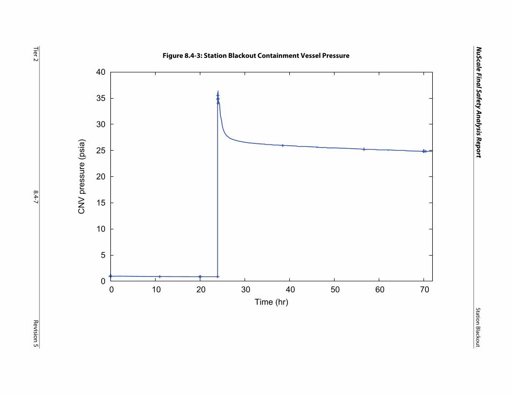
NuScale Final Safety A
nalysis ReportStation Blackout
Tier 28.4-7
Revision 5
Figure 8.4-3: Station Blackout Containment Vessel Pressure
0
5
10
15
20
25
30
35
40
0 10 20 30 40 50 60 70
CN
V p
ress
ure
(psi
a)
Time (hr)
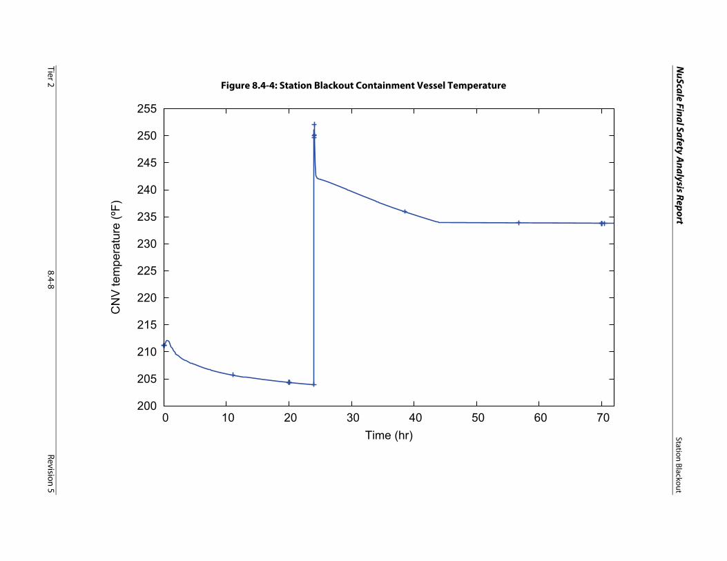
NuScale Final Safety A
nalysis ReportStation Blackout
Tier 28.4-8
Revision 5
Figure 8.4-4: Station Blackout Containment Vessel Temperature
200
205
210
215
220
225
230
235
240
245
250
255
0 10 20 30 40 50 60 70
CN
V te
mpe
ratu
re (º
F)
Time (hr)