part 10 traffic control and communication devices
TRANSCRIPT
Supplement Traffic and Road Use Management Volume 1 – Guide to Traffic Management
Part 10: Traffic Control and Communication Devices (2016) November 2020

Traffic and Road Use Management, Transport and Main Roads, November 2020
Copyright
© The State of Queensland (Department of Transport and Main Roads) 2020.
Licence
This work is licensed by the State of Queensland (Department of Transport and Main Roads) under
a Creative Commons Attribution (CC BY) 4.0 International licence.
CC BY licence summary statement
In essence, you are free to copy, communicate and adapt this work, as long as you attribute the
work to the State of Queensland (Department of Transport and Main Roads). To view a copy of this
licence, visit: https://creativecommons.org/licenses/by/4.0/
Translating and interpreting assistance
The Queensland Government is committed to providing accessible services to
Queenslanders from all cultural and linguistic backgrounds. If you have difficulty
understanding this publication and need a translator, please call the Translating and
Interpreting Service (TIS National) on 13 14 50 and ask them to telephone the
Queensland Department of Transport and Main Roads on 13 74 68.
Disclaimer
While every care has been taken in preparing this publication, the State of Queensland accepts no
responsibility for decisions or actions taken as a result of any data, information, statement or
advice, expressed or implied, contained within. To the best of our knowledge, the content was
correct at the time of publishing.
Feedback
Please send your feedback regarding this document to: [email protected]

Traffic and Road Use Management, Transport and Main Roads, November 2020 i
Contents
Part 10: Traffic Control and Communication Devices (2016) .............................................................1
4.2-1 Cane haulage signs .......................................................................................................................5
1 Introduction .......................................................................................................................... 5
2 Sign types ............................................................................................................................ 5
3 Use of signs ......................................................................................................................... 5
4 Installation of signs .............................................................................................................. 7
5 Removal and covering of signs ........................................................................................... 7
6 For further information ......................................................................................................... 7
4.2-2 Service and tourist signing guides ..............................................................................................8
4.2-3 Wine tourism signing guidelines .................................................................................................9
4.2.4-1 Engine compression braking ............................................................................................. 10
1 Introduction ........................................................................................................................ 10
2 Background ........................................................................................................................ 10
3 Application ......................................................................................................................... 10
4.3.3-1 Target boards for signs ...................................................................................................... 12
4.5-1 Advisory speeds on roundabout diagrammatic signs ............................................................ 13
1 Introduction ........................................................................................................................ 13
2 Current practice ................................................................................................................. 14
3 New practice ...................................................................................................................... 14
4.5-2 Erection of clearance signs ....................................................................................................... 17
1 Introduction ........................................................................................................................ 17
2 Signing requirements ......................................................................................................... 17
3 Vertical clearance measurement ....................................................................................... 17
4 Other considerations ......................................................................................................... 18
4.5.3-1 Support selection for roadside signs and other equipment ........................................... 19
1 Introduction ........................................................................................................................ 19
2 Discussion ......................................................................................................................... 20
3 Summary of approved sign support systems .................................................................... 21
4 Other sign support considerations ..................................................................................... 22
5 Use of standard support selection charts .......................................................................... 24
6 Use of Lattix selection charts ............................................................................................. 24
7 Use of Signfix selection charts .......................................................................................... 35
8 Standard post selection charts (CHS / RHS / TRUSS) ..................................................... 39
5.1.2-1 Non-Transport and Main Roads variable message sign installation applications on
state-controlled roads for displaying road and traffic condition information .............................. 40
1 Overview ............................................................................................................................ 40
2 Installation application ....................................................................................................... 40

Traffic and Road Use Management, Transport and Main Roads, November 2020 ii
3 Messaging restrictions ....................................................................................................... 40
5.3.1-1 Queensland-specific advice for message priorities ........................................................ 42
1 Overview ............................................................................................................................ 42
2 Category 1: Incident messages ......................................................................................... 42
3 Category 1E: Disaster or emergency alerts ...................................................................... 43
4 Category 2: Child abduction message (amber alert) ......................................................... 43
5 Category 3: Traffic management information .................................................................... 44
6 Category 4: Planned roadworks and special events messages ........................................ 44
7 Category 5: Filler messages (community benefit / campaign messages) ......................... 45
5.3.2-1 Abbreviations – Queensland .............................................................................................. 47
5.4-1 Variable message sign statements ........................................................................................... 48
5.6.9-1 Bicycle activated warning signs ........................................................................................ 49
1 Purpose and scope of this section..................................................................................... 49
2 Purpose of active warning signs ........................................................................................ 50
3 When should bicycle activated warning signs be used? ................................................... 51
4 Risks associated with bicycle activated warning signs...................................................... 52
5 When are bicycle activated warning signs not suitable? ................................................... 53
6 Signage specification ......................................................................................................... 54
7 Site assessment and selection process ............................................................................ 57
8 Case studies ...................................................................................................................... 60
5.7-1 Guidelines for the permanent placement of variable speed limit and lane control signs for
motorways, long bridges and tunnels ............................................................................................... 64
1 Introduction ........................................................................................................................ 64
2 Scope ................................................................................................................................. 64
3 Background ........................................................................................................................ 65
4 Display ............................................................................................................................... 68
5 Sign placement .................................................................................................................. 70
6 Maximum and minimum speed displays ........................................................................... 72
7 Mounting arrangements ..................................................................................................... 73
8 Enforcement of variable speed limits................................................................................. 75
9 Associated Intelligent Transport System devices .............................................................. 75
10 Considerations of future upgrade projects ........................................................................ 76
11 Selection of a gantry type for lane use management system, variable speed limit signs
and other signs ............................................................................................................................ 76
5.7-2 Collocation of gantry-mounted variable speed limit signs with static and monochrome
variable message signs ...................................................................................................................... 78
1 Introduction ........................................................................................................................ 78
2 Scopes ............................................................................................................................... 78
3 Collocation of gantry-mounted variable speed limit signs and advance direction signs ... 78

Traffic and Road Use Management, Transport and Main Roads, November 2020 iii
4 Collocation of gantry-mounted variable speed limit and monochrome variable message
signs 80
5.8-1 Use of temporary variable speed limit signs in construction and maintenance work areas
on motorways ...................................................................................................................................... 82
6.3.3-1 Determination of centre line markings adjacent to property access ............................. 83
1 Introduction ........................................................................................................................ 83
2 Assessment criteria ........................................................................................................... 83
3 Line marking ...................................................................................................................... 83
4 Consultation ....................................................................................................................... 84
6.5-1 Bicycle Awareness Zones .......................................................................................................... 85
1 Purpose ............................................................................................................................. 85
2 Bicycle Awareness Zones: description and use ................................................................ 86
3 Design and implementation of Bicycle Awareness Zones ................................................ 95
4 Bicycle Awareness Zones lane configurations and pavement marking layouts ................ 96
5 Bicycle lane design worksheet ........................................................................................ 102
6 Ways to gain on-road space to make provision for on-road cycling (derived from
VicRoads 2001) ......................................................................................................................... 104
6.6-1 Coloured surface treatments for bicycle lanes ..................................................................... 108
1 Introduction ...................................................................................................................... 108
2 Use green-coloured surface treatments selectively ........................................................ 108
3 Effectiveness of green-coloured surface treatments ....................................................... 108
4 Locations where a green-coloured surface treatment may be used ............................... 109
5 Warrants for use of coloured surface treatment .............................................................. 111
6 Factors to consider when choosing coloured surface treatment materials ..................... 112
7 Maintenance considerations ............................................................................................ 112
6.7.2-1 Fire hydrant indication system ........................................................................................ 113
1 Introduction ...................................................................................................................... 113
2 Fire hydrant indication system ......................................................................................... 113
3 System components ........................................................................................................ 114
4 Administration .................................................................................................................. 114
5 Typical arrangement diagrams ........................................................................................ 116
6.8.1-1 Rumble strips ..................................................................................................................... 125
7-1 Bicycle lane separation devices .............................................................................................. 126
1 Purpose and scope of this Supplement ........................................................................... 126
2 Preferred separation device ............................................................................................ 127
3 Historical applications ...................................................................................................... 131
4 Background ...................................................................................................................... 131
5 Further information .......................................................................................................... 143
10.2-1 Implementation of internet-enabled video cameras ...................................................... 144

Traffic and Road Use Management, Transport and Main Roads, November 2020 iv
1 Introduction ...................................................................................................................... 144
2 Key considerations .......................................................................................................... 144
3 Purpose ........................................................................................................................... 144
4 Ensuring privacy .............................................................................................................. 145
5 Copyright ......................................................................................................................... 145
6 Site and maintenance ...................................................................................................... 145
7 Hardware and software ................................................................................................... 146
8 Security ............................................................................................................................ 146
C-1 Abbreviations for use in Queensland on variable message signs ..................................... 147
D.1-1 Approved Queensland-specific variants – problem statements .................................. 148
D.2-1 Approved Queensland-specific variants – location statements ................................... 148
D.3-1 Approved Queensland-specific variants – effect statements ....................................... 148
D.4-1 Approved Queensland-specific variants – attention statements ................................. 149
D.5-1 Approved Queensland-specific variants – action statements ...................................... 149
E-1 Approved Queensland-specific variants – generic messages ............................................ 150

Volume 1: Part 10 – Traffic Control and Communication Devices
Traffic and Road Use Management, Transport and Main Roads, November 2020 5
4 Traffic signs
4.2 Types of signs
4.2-1 Cane haulage signs
1 Introduction
This supplement outlines the recommended signing practice for erection of cane haulage signs on all
roads in the vicinity of cane haulage operations during the cane haulage and crushing season.
2 Sign types
2.1 Area wide signs
G9-Q03
2.2 Warning signs
W5-Q07 CANE HAULING AHEAD is a temporary warning sign, with black letters on yellow fabric
background. An alternative is a hinged sign, TC9757 CANE HAULING NEXT … km, which has a black
legend and border on yellow reflectorized background.
W5-Q07 TC9757
3 Use of signs
The G9-Q03 sign is used as an area-wide advisory sign, to be displayed during harvest seasons at
entrances to sugar cane growing areas, to advise motorists of possible cane hauling activities. It
should incorporate hinges for folding the sign during the non-harvest season. Repeater signs may be
erected within the larger cane growing areas at intervals of approximately 1 km.
W5-Q07 is a temporary flag-type sign made of PVC-coated nylon, with wooden handles at the top and
bottom. These are used to warn motorists of actual cane hauling in progress. These signs are only
displayed immediately in advance of cane hauling activities and are to be removed when no hauling
activities are in progress.

Volume 1: Part 10 – Traffic Control and Communication Devices
Traffic and Road Use Management, Transport and Main Roads, November 2020 6
Figure 3 shows a typical layout where these signs are used.
TC9757 is a fixed warning sign that can be used in lieu of the use of temporary sign W5-Q07 on
sections of roads where extensive and regular haulage occurs. The signs should be removed or
covered at the end of haulage.
Figure 3 – Location of CANE HAULING AHEAD signs
Notes:
1. Provide additional CANE HAULING AHEAD signs where section exceeds 1 km in length. Signs should
be provided such that spacing between signs does not exceed 1 km.
2. Additional CANE HAULING AHEAD signs are also required at intersections within the area of cane
hauling activity.

Volume 1: Part 10 – Traffic Control and Communication Devices
Traffic and Road Use Management, Transport and Main Roads, November 2020 7
4 Installation of signs
Transport and Main Roads will, at its cost, install and maintain the area-wide advisory signs (G9-Q03).
The temporary warning sign W5-Q07 requires a post or a suitable frame for erection. The installation
of a post or the siting of a frame shall not be carried out without approval from Transport and Main
Roads or the appropriate local government. On Queensland roads, approved facilities will be installed
to departmental standards, by the department, at the user’s expense. The current standard is shown
on drawing TC9308 for supporting posts. The fabric signs are not supplied by the department but may
be purchased from sign suppliers. Advice of suitable suppliers can be obtained from Transport and
Main Roads District Offices or [email protected].
An alternative to the use of posts for the fabric signs is to use appropriate supporting frames. These
require special fittings and advice should be obtained from the department before purchase.
The warning sign TC9757 can be installed at sites agreed upon by Transport and Main Roads, and
the relevant mill, providing that:
• the user will pay all costs
• TC9757 will be more effective than temporary signs
• all warning signs are removed or covered at the end of haulage.
5 Removal and covering of signs
The area-wide sign G9-Q03 is to be covered or the message appropriately hidden during the
non-harvest season. Responsibility for folding and securing of these signs rests with the respective
mill. Sugar cane haulage should not occur before the signs are open, nor continue after the signs are
closed.
The fabric signs (W5-Q07 CANE HAULING AHEAD) are to be displayed only when cane hauling is in
progress and at no other time. It will be the responsibility of the user to display and dismantle this type
of sign. The same applies to any TC9757 signs. The mill should have agreed arrangements with the
cane growers to reinforce the department’s conditions of usage or local government requirements.
6 For further information
For more information on application, approval and conditions of use regarding cane haulage signs,
see Other matters requiring approval: Road corridor permits on the departmental website.

Volume 1: Part 10 – Traffic Control and Communication Devices
Traffic and Road Use Management, Transport and Main Roads, November 2020 8
4.2-2 Service and tourist signing guides
Refer to Tourist and service signs guideline available on the Transport and Main Roads website.

Volume 1: Part 10 – Traffic Control and Communication Devices
Traffic and Road Use Management, Transport and Main Roads, November 2020 9
4.2-3 Wine tourism signing guidelines
Refer to Tourist and service signs guideline available on the Transport and Main Roads website.

Volume 1: Part 10 – Traffic Control and Communication Devices
Traffic and Road Use Management, Transport and Main Roads, November 2020 10
4.2.4 Other signs and markings
4.2.4-1 Engine compression braking
1 Introduction
The objective of this supplement is to minimise noise levels from trucks and heavy vehicles while
travelling through residential areas.
2 Background
Many heavy vehicles are fitted with engine compression brakes to relieve the loads exerted on
traditional braking systems working at the wheels.
Most states and territories have produced guidelines for the use of engine brake signage, but most
see signage as a short-term measure that will only be used until effective regulation of engine noise is
implemented.
Trucks are defined as those vehicles that are Class 3 or above in the Austroads Vehicle Classification
system.
3 Application
3.1 Criteria for installation of signs
Truck noise signs may be installed on roads where:
• the posted speed limit is 80 km/h or less – generally, signs should not be required on roads
with a speed limit above 80 km/h, but may be considered in special circumstances
• abutting areas are predominantly residential rather than commercial and adjoining built-up
area as defined in the Transport Operations (Road Use Management—Road Rules)
Regulation 2009
• the 12-hour truck volume is at least 60 at night (7pm–7am) or at least 500 during the
day (7am–7pm), and/or
• in advance of a requirement for traffic to stop or slow (for example, signals, roundabout,
pedestrian crossing STOP or GIVE WAY signs, curves, or road sections commonly subject to
congestion) or steep downgrades.
Sites shall not be selected on the basis of managing an individual complainant at a specific location.
3.2 Location of signs
• Signs shall be installed 300 metres or more in advance of a built-up area.
• Signs shall be installed 300 metres or more in advance of a requirement for traffic to stop or
slow (for example, signals, roundabout, pedestrian crossing STOP or GIVE WAY signs,
curves, or road sections commonly subject to congestion) or steep downgrades.
• Signs shall be sighted at least 5 kilometres apart on a particular route, for each direction of
travel or at least 10 kilometres apart where the route is in excess of 20 kilometres.
• Only one sign should be used on each entrance to a rural town.

Volume 1: Part 10 – Traffic Control and Communication Devices
Traffic and Road Use Management, Transport and Main Roads, November 2020 11
3.3 Sign details
Details of the truck noise advisory signs are given on drawing TC9709.
RESIDENTIAL AREA is a white legend on a black patch.

Volume 1: Part 10 – Traffic Control and Communication Devices
Traffic and Road Use Management, Transport and Main Roads, November 2020 12
4.3 Design of sign faces
4.3.3 Colour of signs
4.3.3-1 Target boards for signs
This content has been incorporated into the Queensland Manual of Uniform Traffic Control
Devices (MUTCD) Part 1.

Volume 1: Part 10 – Traffic Control and Communication Devices
Traffic and Road Use Management, Transport and Main Roads, November 2020 13
4.5 Location and placement of signs
4.5-1 Advisory speeds on roundabout diagrammatic signs
1 Introduction
The purpose of this supplement is to introduce the use of a supplementary advisory speed information
panel, in conjunction with advance direction signs at isolated roundabouts on high-speed roads.
Advance roundabout direction signs are used to indicate to drivers the presence of a roundabout on
the road ahead and the layout of the roads intersecting at the roundabout.
The advance roundabout direction sign may take the form of a standard advance direction sign for
simple roundabout layouts, for example, G1-5 type as shown in Figure 1(A).
Figure 1(A) – Standard advance roundabout direction sign
Where the geometry of a multi-lane roundabout is such that selection of the correct lane is not clearly
apparent to drivers with a standard advance roundabout direction sign, a special advance direction
sign indicating the lane(s) to be used is usually provided as shown in Figure 1(B).
Figure 1(B) – Special advance roundabout direction sign
Volume 1: Part 10 – Traffic Control and Communication Devices
Traffic and Road Use Management, Transport and Main Roads, November 2020 14
At isolated roundabouts on high-speed roads in rural and outer metropolitan areas, drivers may not
perceive the need to reduce speed in sufficient time to slow down and negotiate the roundabout in
safety.
The supplementary advisory speed information panel has been introduced to assist in addressing this
need. It is based on practice in Victoria which, for some years, has used the advisory speed panel to
supplement roundabout advance direction signing for this purpose.
2 Current practice
Roundabouts are designed so that through movements by cars within the roundabout are typically
limited to a maximum speed of 50 km/h. This is achieved by adjusting the geometry of the entry
carriageway to ensure adequate deflection of the through vehicle paths, by one or more of the
following:
i) alignment of the entry carriageway and the shape, size and position of approach splitter
islands
ii) provision of a suitable size of central island.
On high-speed roads in rural and outer metropolitan areas, additional measures may be needed to
assist in controlling the speed of traffic on the approaches to the roundabout.
Current practice for controlling vehicle speeds on high-speed approaches to roundabouts in
south-east Queensland includes provision of a reverse curve alignment and the reduction of the
posted speed limit to 60 km/h, with changes in the posted speed limit in accordance with the
Queensland Manual of Uniform Traffic Control Devices (MUTCD). High-impact warning signs (on a red
background), and rumble strips, are also used where appropriate.
Even with these measures in place, some drivers may not appreciate that a substantial speed
reduction is needed to ensure they are able to travel through the roundabout at a 'safe' speed,
entering the roundabout at higher speeds. This reduces their safety and the safety of all other
roundabout users.
3 New practice
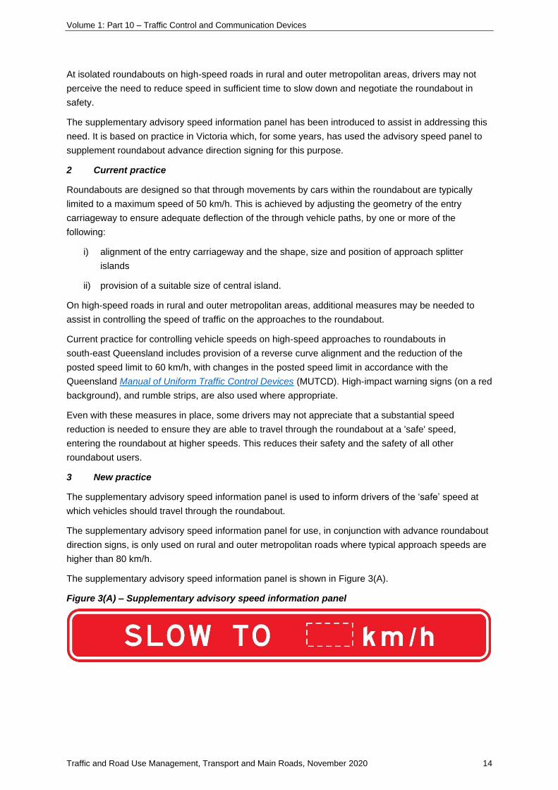
The supplementary advisory speed information panel is used to inform drivers of the ‘safe’ speed at
which vehicles should travel through the roundabout.
The supplementary advisory speed information panel for use, in conjunction with advance roundabout
direction signs, is only used on rural and outer metropolitan roads where typical approach speeds are
higher than 80 km/h.
The supplementary advisory speed information panel is shown in Figure 3(A).
Figure 3(A) – Supplementary advisory speed information panel

Volume 1: Part 10 – Traffic Control and Communication Devices
Traffic and Road Use Management, Transport and Main Roads, November 2020 15
The advisory speeds shown on the supplementary advisory speed information panel apply to through
movements only as it is reasonable to assume that drivers of vehicles turning at a roundabout would
already be aware of the need to slow down to turn.
In view of this, the supplementary advisory speed information panel is not normally used where drivers
are approaching a T-intersection roundabout along the ‘stem’ or terminating road approach. In this
case, an alternative information panel REDUCE SPEED NOW, as shown in Figure 3(B), may be used
where there is an existing or potential safety concern. This alternative information panel may also be
considered for use on an approach which does not have a clearly-defined through movement, but
where at least one movement at the roundabout might not be perceived by drivers as a turn
movement requiring substantial speed reduction.
Figure 3(B) – Alternative REDUCE SPEED NOW information panel
The advisory speed for a particular roundabout approach is determined in the same manner as
advisory speed signing on curves along rural roads. A ball bank indicator or other suitable means is
used to determine the advisory speed in accordance with procedures in Part 2 of the MUTCD.
Calculated speed values are then rounded to the nearest multiple of 10 km/h for display as the ‘safe’
speed on the supplementary panel.
Where there is more than one lane available for through movements on the circulating carriageway for
the particular approach to the roundabout, the ‘safe’ speed is determined for each lane and the lower
speed shown on the supplementary panel. In this case, the car must remain in one lane as it passes
through the roundabout, rather than changing lanes through the roundabout to drive the path of least
deflection.
The supplementary advisory speed information panel, for example, SLOW TO 40 km/h and the
alternative information panel REDUCE SPEED NOW will be designed as part of the advance
roundabout diagrammatic direction sign, with letter heights consistent with the balance of the sign, but
with a white legend on red background.
Examples of supplementary advisory speed information panels are shown in Figure 3(C)
and Figure 3(D). Examples of alternative information panel REDUCE SPEED NOW are shown in
Figure 3(E).

Volume 1: Part 10 – Traffic Control and Communication Devices
Traffic and Road Use Management, Transport and Main Roads, November 2020 16
Figure 3(C) – Example of supplementary advisory speed information panel fitted as a separate
panel under an existing sign
Figure 3(D) – Examples of supplementary advisory speed information panel incorporated into
the direction sign (preferred option)
Figure 3(E) – Examples of alternative information panel REDUCE SPEED NOW incorporated
into the direction sign (preferred option)

Volume 1: Part 10 – Traffic Control and Communication Devices
Traffic and Road Use Management, Transport and Main Roads, November 2020 17
4.5-2 Erection of clearance signs
1 Introduction
This supplement provides advice on signing requirements at locations with restricted vertical
clearances.
The Heavy Vehicle (Mass, Dimension and Loading) National Regulation nominates the height
restrictions for vehicles.
These limits may be exceeded only with the prior written permission of the Superintendent of
Traffic (Queensland Police Service) or performance guidelines issued by the Chief
Executive (Transport and Main Roads) and subject to compliance with any conditions of such
permission or guidelines. The limits apply to the motor vehicle, together with its loading and
equipment.
2 Signing requirements
The signing requirements at underpasses are set out in Part 2 of the Manual of Uniform Traffic
Control Devices. Clearances are specified in metres to one decimal place.
3 Vertical clearance measurement
To determine the appropriate clearance height to be shown on the sign, the minimum clearance above
the carriageway (or lane as appropriate) is measured to two decimal places, and then rounded to the
nearest 0.1 m below the measured height. A carriageway is that portion of the road devoted
particularly to the use of vehicles, inclusive of shoulders and auxiliary lanes.
In determining the minimum clearance, care must be taken to measure it at the correct point, taking
account of road cross fall and bridge grade and geometry. On two-way undivided carriageways, only
one value for minimum clearance is to be posted. On divided carriageways, the minimum clearance
applicable to each direction is to be posted for viewing on the approach side only. It may also be
necessary to allow for a sag vertical alignment correction.
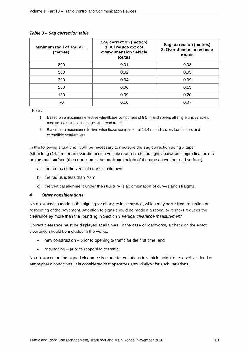
Where it is necessary to make allowance for any sag curvature in the roadway under the structure, the
following table can be used to determine the amount by which the measured clearance should be
reduced because of the curvature. In such cases, the procedure is:
a) measure minimum height clearance to two decimal places
b) read the sag correction, using Table 3 following – subtract the sag correction from the
measured minimum clearance
c) round down to nearest 0.1 m below this figure.
Volume 1: Part 10 – Traffic Control and Communication Devices
Traffic and Road Use Management, Transport and Main Roads, November 2020 18
Table 3 – Sag correction table
Minimum radii of sag V.C.
(metres)
Sag correction (metres)
1. All routes except
over-dimension vehicle
routes
Sag correction (metres)
2. Over-dimension vehicle
routes
800 0.01 0.03
500 0.02 0.05
300 0.04 0.09
200 0.06 0.13
130 0.09 0.20
70 0.16 0.37
Notes:
1. Based on a maximum effective wheelbase component of 9.5 m and covers all single unit vehicles.
medium combination vehicles and road trains
2. Based on a maximum effective wheelbase component of 14.4 m and covers low loaders and
extendible semi-trailers
In the following situations, it will be necessary to measure the sag correction using a tape
9.5 m long (14.4 m for an over-dimension vehicle route) stretched tightly between longitudinal points
on the road surface (the correction is the maximum height of the tape above the road surface):
a) the radius of the vertical curve is unknown
b) the radius is less than 70 m
c) the vertical alignment under the structure is a combination of curves and straights.
4 Other considerations
No allowance is made in the signing for changes in clearance, which may occur from resealing or
resheeting of the pavement. Attention to signs should be made if a reseal or resheet reduces the
clearance by more than the rounding in Section 3 Vertical clearance measurement.
Correct clearance must be displayed at all times. In the case of roadworks, a check on the exact
clearance should be included in the works:
• new construction – prior to opening to traffic for the first time, and
• resurfacing – prior to reopening to traffic.
No allowance on the signed clearance is made for variations in vehicle height due to vehicle load or
atmospheric conditions. It is considered that operators should allow for such variations.

Volume 1: Part 10 – Traffic Control and Communication Devices
Traffic and Road Use Management, Transport and Main Roads, November 2020 19
4.5.3 Lateral placement and height
4.5.3-1 Support selection for roadside signs and other equipment
1 Introduction
This supplement provides guidance on the selection of supports for roadside signs and other devices
used beside the road including, but not limited to, cameras, solar panels, and so on. Performance of
different types of posts is discussed with limitations of use placed on classes of post as necessary.
There are three types of support that have been certified for use by Transport and Main Roads in
Queensland:
• standard support posts
• Lattix energy absorbing posts
• Signfix frangible support system.
Selection of each of these support systems require similar design processes using product-dedicated
specific wind loading charts to determine the most appropriate and efficient sign support structure.
1.1 Standard support posts
This option maintains a standard approach for the determination of sign supports in Circular Hollow
Section (CHS) pipe, Rectangular Hollow Section (RHS) pipe and truss supports. Supports for signs
having a surface area greater than 40 m² should be designed and certified by a registered
professional structural engineer. Supports for sign with surface areas less than 40 m² may be
calculated in conjunction with either:
a) the design procedures outlined in the Traffic and Road Use Management manual, Volume 3
Signing and Pavement Marking Part 5 Design Guide for Roadside Signs (TRUM Vol 3 Pt 5)
This method of sign support selection enables the designer to determine manually the most
appropriate support structures by calculations using sign height, sign surface areas (in
three categories of up to 10 m², up to 28 m² and up to 40 m²), environmental
specifications (within wind loading regions A, B, C and D based on Australian Standard
AS 1170.2) and foundation strengths. Post-selection charts are included in TRUM Vol 3 Pt 5.
b) use of the TraSiS (Traffic Sign Support) software design tool
TraSiS is a computer software design tool developed by Transport and Main Roads to
calculate and select sign supports. The calculations used in TraSiS are based on the same
methods outlined in Appendix B of TRUM Vol 3 Pt 5, subject to the input of sign parameters,
terrain profiles and environmental conditions.
TraSiS has output capabilities displaying separate support design details and project-based
ordering detail summaries to assist in the manufacture of road signs and their supports, as
well as standard construction installation details.

Volume 1: Part 10 – Traffic Control and Communication Devices
Traffic and Road Use Management, Transport and Main Roads, November 2020 20
1.2 Lattix energy absorbing posts
• Single post, capable of supporting signs of up to 13 m² in Wind Region A. 10 m² in Wind
Region B and 8 m² in Wind Region C.
• Multi-post, capable of supporting signs of up to 28 m².
Lattix support designs should use procedures outlined in Section 6 Use of Lattix selection charts.
1.3 Signfix frangible support system
• Single post, capable of supporting signs of up to 9 m² in Wind Region A, 6 m² in Wind
Region B and 4 m² in Wind Region C.
• Multi-post, capable of supporting signs of up to 16 m² in Wind Region A, 12 m² in Wind
Region B and 10 m² in Wind Region C.
Signfix support designs should use procedures outlined in Section 7 Use of Signfix selection charts.
2 Discussion
Signs, road lighting, traffic signals, cameras and other roadside furniture often need to be placed close
to the travelled way. This places them inside the clear zone where they, and their supports, become a
hazard to motorists. Supports need to be strong enough to resist wind loads, yet safe if struck by an
errant vehicle. Currently there are four classes of supports that are considered to be relatively safe for
occupants of vehicles that strike them.
2.1 Frangible-sized rigid steel posts
Frangible-sized steel posts are described in AS 1742.2: 2009 Manual of Uniform Traffic Control
Devices Part 2 Traffic Control Devices for General Use. The concept is that the post is weak and will
collapse safely when struck by a vehicle. The vehicle usually runs over the post.
2.2 Slip base posts
Slip base posts are made from steel sections with mechanisms to allow the post to break away at the
base and to hinge underneath the sign face, allowing a light vehicle to pass underneath with relatively
little damage.
2.3 High-energy absorbing posts
High-energy absorbing posts deform locally where struck and bend around the vehicle, slowing the
vehicle in a controlled manner similar to a non-redirective crash cushion on a crash barrier. This type
of post usually ‘captures’ the errant vehicle, stopping it while it is still in contact with the post.
High-energy absorbing posts are not designed to detach from the foundation. These posts must be
long enough to allow controlled reduction in velocity of the vehicle so that the G-forces generated by
the deceleration are survivable. Typically, these posts are used for road lighting as those poles
provide the required length to slow the vehicle.
2.4 Low-energy absorbing posts
Low-energy absorbing posts transfer little of the vehicle’s kinetic energy to the post. Tests have shown
minimal reduction in vehicle speed through impact. The posts can collapse by bending with the vehicle
running over the post or the post can break away or do both.

Volume 1: Part 10 – Traffic Control and Communication Devices
Traffic and Road Use Management, Transport and Main Roads, November 2020 21
3 Summary of approved sign support systems
The following is a summary of approved sign support systems.
3.1 Rigid steel posts
Rigid steel posts of any size may be used behind a road safety barrier that is shielding another hazard
and the barrier is in a suitable position for the sign location. Rigid steel posts may also be located
unprotected where they cannot be reached by vehicles which run off the road.
3.2 Frangible-sized rigid steel posts
Rigid steel posts conforming to AS 1163:2009 Cold-formed structural steel hollow sections may be
used at any place where the size of the post is considered frangible for the likely impact speed. For
multiple post signs, post spacing must be at least 1.5 m between the posts.
3.3 Steel slip base posts
Only steel slip base posts complying with Standard Drawings 1363, 1364, 1365, 1368 and fabricated
by companies on the Transport and Main Roads Approved Supplier List – Approved sign supports are
allowed.
3.4 High-energy absorbing posts
There are currently no products approved by the department for this class of post.
3.5 Low-energy absorbing posts
3.5.1 Lattix energy absorbing posts
Lattix energy absorbing posts are approved by Transport and Main Roads. Lattix is made from
marine-grade aluminium extrusion that is slotted and stretched. The unique expanded shape gives
them strength for wind load and softness in a collision. The post is factory bolted to a base plate
which, in turn, is bolted to the foundation on site. In an impact, the post deforms locally and may
detach from the base plate. Lattix posts can be hit at any angle.
All sizes of Lattix may be used for single or multiple-post use for roadside signs anywhere on the road
network. Lattix posts may be used for single post use for signs ranging in width from 1200 mm to
2500 mm. The standard two-post spacing is 0.6 x the width of the sign; that is. 2500 x 0.6 = 1500 mm.
Any sign with less width should be installed on one safety post or be shielded by a barrier.
Lattix posts are designated as follows.
The first two numbers represent the number of sides the post has.
• 33 (triangular section)
• 44 (square section).
The second two numbers represent the width of the sides in centimetres.
• 12 (125 mm), 20 (200 mm), 25 (250 mm), 38 (380 mm).
Example – Lattix 4420 = a four-sided post with a width of 200 mm.
Lattix types are 3320, 3325, 4412, 4420, 4425 and 4438. Selection charts follow.
Each step up in size represents approximately double the bending moment and torsion moment
capacity from the previous type.

Volume 1: Part 10 – Traffic Control and Communication Devices
Traffic and Road Use Management, Transport and Main Roads, November 2020 22
3.5.2 Signfix aluminium frangible pole system
Signfix poles are available in 50, 65, 80, 90 and 100 NB sizes.
The Signfix aluminium frangible pole system is approved by Transport and Main Roads. Signfix poles
are manufactured from high-strength marine-grade alloy with typical yield strength of 275 MPa. It is a
patented system that works with a purpose-made ground sleeve designed to be a snug fit between the
pole and the sleeve.
Sleeves are supplied up to 1 metre in length, depending on the pole diameter and length. The sleeves
are set in concrete foundations designed to meet local engineering requirements.
The sleeve top acts as a shear point and, combined with the molecular structure of the alloy, will,
under sudden impact, bend the pole at the point of impact and will ultimately shear and breakaway at
the sleeve top. The pole flues are designed to further assist in the breakaway process by reducing the
external surface area of the pole. Frangibility is multidirectional.
Manufacturer’s specifications and recommendations shall be followed in the installation of the Signfix
aluminium frangible pole system.
Section 7 Use of Signfix selection charts shows Signfix Wind Loading Charts for each of the wind
regions A, B, C and D throughout Australia, based on those set in Australian Standard AS 1170.2 (for
representation of these regional boundaries, refer to Figure 4).
Use of the appropriate chart based on desired wind region, surface area of the sign/s and height of the
sign aboveground level is used to determine optimal number and size of the poles to be used for each
particular installation.
4 Other sign support considerations
It should be noted that some of these supports have inherent limitations on their performance due to
their design.
Due to their low strength, frangible sized steel posts are not suitable for large signs.
Their low strength, while supporting the small sign, still allows the supports to bend when struck by a
vehicle or subjected to high wind forces (thereby protecting the sign from being dislodged and
becoming a projectile).
Where large signs are to be installed in a clear zone and there may be a requirement to use either slip
base or energy-absorbing supports that will ‘give way’ in order to minimise the impact of the vehicle, a
slip base design may be used.
For slip base supports to operate effectively, all design specifications must be adhered to. These
include:
a) fuse plates welded as per Standard Drawing 1365, oriented correctly and located 100 mm
from the bottom edge of the sign
b) base plate bolts tensioned to allow both base plates to slip when the support is struck by a
vehicle (it is very important that the securing bolts are tensioned to the correct tension;
incorrectly tensioning may interfere with the ‘slipping’ action of the two matched base plates)
c) the foundation stubs installed according to Standard Drawing 1363, which requires the base
plates to be installed at 100 mm above the surrounding terrain – not adhering to these

Volume 1: Part 10 – Traffic Control and Communication Devices
Traffic and Road Use Management, Transport and Main Roads, November 2020 23
specifications may cause ‘snagging’ of the impacting vehicle’s chassis and affecting the
operation of the slip base or the possibility of an undesirable rapid deceleration of the vehicle
d) ensuring single slip base post designs (Standard Drawing 1368) and multi-post slip base
designs (Standard Drawing 1365) are not mixed or interchanged
e) the height of the support posts is to be sufficient to allow the bottom of the sign to be no less
than 2.1 metres from the ground to allow the vehicle to pass under the sign / load on impact
f) the spacing of any two slip base supports being no less than 1500 mm to minimise the risk of
a vehicle sweeping through more than one of the supports, thereby affecting the slipping
action
g) careful consideration when slip base posts are installed on steep filled slopes to ensure the
impact of the vehicle will still be low on the supports to allow the correct operation of the slip
base
h) ensuring the orientation of the slip bases are correctly installed to operate on a proposed
impact angle
i) use of accredited manufacturers to supply certified slip base supports. A full list of accredited
manufacturers is available from Transport and Main Roads.
Where supports are required in a clear zone, Lattix and Signfix type supports may also be used.
For all support options to operate effectively, they must be installed according to the manufacturer’s
specifications and proper engineering processes.
Figure 4 – Australian wind regions

Volume 1: Part 10 – Traffic Control and Communication Devices
Traffic and Road Use Management, Transport and Main Roads, November 2020 24
5 Use of standard support selection charts
Refer to TRUM Vol 3 Pt 5 Appendix B.
Note: TraSiS (Traffic Sign Support) may be used. This is a software program that can be downloaded from the
Transport and Main Roads website. This automatically selects sign supports according to the relative specific
user data input.
6 Use of Lattix selection charts
Use Figure 3.1 from AS 1170.2:2002 Structural design actions – Wind actions to determine the wind
region of the site. Figure 4 has been reproduced from AS 1170 for convenience of the reader.
Lattix sign supports for signs with surface areas and wind regions are available on separate specific
single and multiple support selection charts in Section 6.1 and Section 6.2 respectively. For signs with
larger surface areas, other support options mentioned in this supplement should be considered.
Note: If the sign site is installed in an exposed location, a selection chart for the next higher wind region should be
used.
6.1 Single-post selection
Single-post selection charts are shown following.
If the sign width is less than 2.6 m, use the single-post chart first. Check that the Maximum Sign
Stiffener Overhang will not exceed the values shown in TRUM Vol 3 Pt 5 Appendix B Table B2. From
the sign size and ground profile, calculate the height to centre of pressure, that is, 0.5 x sign height,
plus clearance from bottom of centre of sign to ground level. Lattix requires a minimum of 2 m
clearance, so a light vehicle can run underneath the sign. Next, calculate the area of the sign face(s).
On the graph, take a horizontal line from the height to centre of pressure across until it intersects with
a vertical line from the area of the sign. The next curve to the right of the intersection point represents
the smallest Lattix post that can be used.
Consider this worked example for a GE9-2, shown at Figure 6.1(B)).
The sign is 1400 mm x 1800 mm, wind region is B. Sign is to have 2.5 m clearance above road level.
Assume ground clearance to be 2.925 m. Height to Centre of Pressure will be 3.825 m. Area is
1.4 x 1.8 = 2.52 m².
Select the Chart for Wind Region B and take a horizontal line from just under 3.9 for Height to Centre
of Pressure. Now, take a vertical line from halfway between ‘2’ and ‘3’ for the area. A curve to the right
from the point at which they intersect is for 4420 / 3325; however, this curve stops below the horizontal
line. Go to the next curve which is for 4425. This is the correct post to use.

Volume 1: Part 10 – Traffic Control and Communication Devices
Traffic and Road Use Management, Transport and Main Roads, November 2020 25
Figure 6.1(A) – Lattix single post selection chart (Wind Region A)

Volume 1: Part 10 – Traffic Control and Communication Devices
Traffic and Road Use Management, Transport and Main Roads, November 2020 26
Figure 6.1(B) – Lattix single post selection chart (Wind Region B)

Volume 1: Part 10 – Traffic Control and Communication Devices
Traffic and Road Use Management, Transport and Main Roads, November 2020 27
Figure 6.1(C) – Lattix single post selection chart (Wind Region C)

Volume 1: Part 10 – Traffic Control and Communication Devices
Traffic and Road Use Management, Transport and Main Roads, November 2020 28
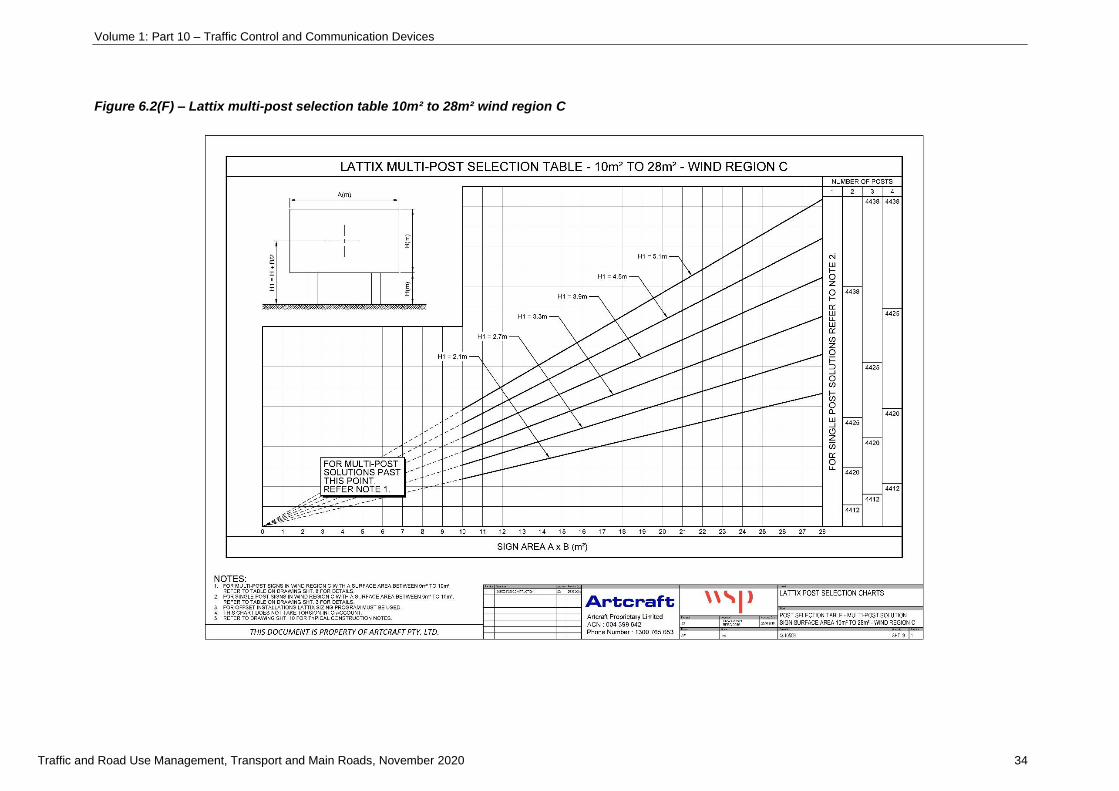
6.2 Multiple post selection
For signs over 2.5 m wide, use the multiple-post selection charts shown following.
From the sign size and ground profile, calculate the height to centre of pressure, that is, 0.5 x sign
height, plus clearance from bottom of centre of sign to ground level. Lattix requires a minimum of 2 m
clearance, so a light vehicle can run underneath the sign. Next, calculate the area of the sign face(s).
On the chart, find the oblique line that represents the height to centre of sign across until it intersects
with a vertical line from the area of the sign. From there, take a horizontal line to the right. The most
economical way to use Lattix is to specify the least number of posts.
Consider this worked example for a sign is 5 m x 3 m in Wind Region B (Figure 6.2(E)). Sign is to
have 2.2 m clearance above road level. Assume ground clearance to be 3.075 m. Height to Centre of
sign will be 4.575 m. Area is 5 x 3 = 15 m².
Select the Chart for Wind Region B and follow the oblique line marked H1 = 4.5 m. This represents the
Height to Centre of sign line. Now, take a vertical line from 15 m². Take a horizontal line to the right
from the point at which they intersect. The line shows 2 x 4425 posts. These are the correct posts to
use. Check maximum stiffener overhang from Table B.2 in TRUM Vol 3 Pt 5 Appendix B is okay.
Check spacing from Table B.1 in TRUM Vol 3 Pt 5 Appendix B is okay.
The chart shows you may also use 4 x 4420, but this would cost more as a total and the spacing
would be only 1.25 m, which is less than 1.5 m and, therefore, unacceptable.
Note that the Lattix support selection is available for both single and multiple supports for signs with surface areas
outlined in Section 1.2 Lattix energy absorbing posts. For signs with larger areas, other standard supports
mentioned in Section 1.1 Standard support posts of this supplement should be considered.

Volume 1: Part 10 – Traffic Control and Communication Devices
Traffic and Road Use Management, Transport and Main Roads, November 2020 29
Figure 6.2(A) – Lattix multi-post selection table 0m² to 10m² wind region A

Volume 1: Part 10 – Traffic Control and Communication Devices
Traffic and Road Use Management, Transport and Main Roads, November 2020 30
Figure 6.2(B) – Lattix multi-post selection table 0m² to 10m² wind region B

Volume 1: Part 10 – Traffic Control and Communication Devices
Traffic and Road Use Management, Transport and Main Roads, November 2020 31
Figure 6.2(C) – Lattix multi-post selection table 0m² to 10m² wind region C

Volume 1: Part 10 – Traffic Control and Communication Devices
Traffic and Road Use Management, Transport and Main Roads, November 2020 32
Figure 6.2(D) – Lattix multi-post selection table 10m² to 28m² wind region A

Volume 1: Part 10 – Traffic Control and Communication Devices
Traffic and Road Use Management, Transport and Main Roads, November 2020 33
Figure 6.2(E) – Lattix multi-post selection table 10m² to 28m² wind region B
Volume 1: Part 10 – Traffic Control and Communication Devices
Traffic and Road Use Management, Transport and Main Roads, November 2020 34
Figure 6.2(F) – Lattix multi-post selection table 10m² to 28m² wind region C

Volume 1: Part 10 – Traffic Control and Communication Devices
Traffic and Road Use Management, Transport and Main Roads, November 2020 35
7 Use of Signfix selection charts
Use Figure 3.1 from AS 1170.2:2002 Structural design actions – Wind actions to determine the Wind
Region of the site. Figure 4 has been reproduced from AS 1170 for convenience of the reader.
Signfix sign supports for signs with surface areas and wind regions outlined in Section 1.3 Signfix
frangible support system are available from specific support selection charts (following). For signs with
larger surface areas, other support options mentioned in this supplement should be considered.
Major considerations for the installation of Signfix aluminium fluted poles
• Using Signfix Wind Loading Charts for regions A, B and C (refer to following) as appropriate to
determine the correct pole size and number of poles to be used for each particular installation.
• It is recommended foundation details are obtained from a local engineer, prior to any
installation or by footing details determined in TRUM Vol 3 Pt 5.
• Foundations should be excavated to the required depth maintaining a minimum diameter of
400 mm.
• Setting out and pouring concrete on multi-pole sites the kerbside socket should always be
installed first.
• The sleeve must be centralised in the hole and set on a concrete base, ensuring the sleeve
top is between 50–100 mm above ground level.
• It is important to ensure during the final pour the sleeve remains perpendicular.
• For adequate foundation strength, it is recommended not less than 28 mpa concrete is used.
• For frangibility to work within the requirements of NCHRP-350, all pole sizes 65 mm NB and
above must be installed using a matching sleeve and all sockets must be fully encased using
wet premixed concrete.
• To prevent difficulty in removing the security bolt from a damaged or bent pole, all sleeves
must be sited with the locking device facing oncoming traffic.
• It is recommended the security locking bolts are evenly tightened between 10 and 12 Nm.
• The stainless-steel Transition Shoe must be fitted between the pole and locking bolts prior to
tightening.
• In sandy conditions, it is recommended that a silicone bead is placed around the sleeve top to
prevent the ingress of sand into the sleeve. It has been found that sand deposits between the
pole and sleeve can wedge the pole and prevent removal.
• To reduce water ingress, standard galvanised post cap or equivalent must be fitted.
• Restraint devices are recommended to be fitted in high pedestrian areas.

Volume 1: Part 10 – Traffic Control and Communication Devices
Traffic and Road Use Management, Transport and Main Roads, November 2020 36
Figure 7(A) – Signfix frangible fluted poles: Wind region A

Volume 1: Part 10 – Traffic Control and Communication Devices
Traffic and Road Use Management, Transport and Main Roads, November 2020 37
Figure 7(B) – Signfix frangible fluted poles: Wind region B

Volume 1: Part 10 – Traffic Control and Communication Devices
Traffic and Road Use Management, Transport and Main Roads, November 2020 38
Figure 7(C) – Signfix frangible fluted poles: Wind region C

Volume 1: Part 10 – Traffic Control and Communication Devices
Traffic and Road Use Management, Transport and Main Roads, November 2020 39
8 Standard post selection charts (CHS / RHS / TRUSS)
Standard post selection charts are contained in the Traffic and Road Use Management manual,
Volume 3 Signing and Pavement Marking Part 5 Design guide for roadside signs.

Volume 1: Part 10 – Traffic Control and Communication Devices
Traffic and Road Use Management, Transport and Main Roads, November 2020 40
5 Electronic signs
5.1 Variable Message Signs
5.1.2 Applications
5.1.2-1 Non-Transport and Main Roads variable message sign installation
applications on state-controlled roads for displaying road and traffic condition
information
1 Overview
The purpose is to provide advice to ensure road safety on Queensland roads is not compromised in
the operation of variable message signs (VMS) whilst supporting communication with the local
community.
The conditional use of VMS by other state agencies, local government or private road operators on
Queensland roads can provide benefits for communities and motorists.
Any state agency, local government or private road operator seeking to purchase and install a
VMS device should seek early advice from the relevant Transport and Main Roads office.
2 Installation application
Any organisation seeking to install a device within Queensland’s state-controlled road network must
first apply for a Road Corridor Permit.
2.1 Application technical requirements
The VMS must comply with Transport and Main Roads Technical Specification MRTS202 Variable
Message Signs.
It is expected, in providing approval for installation of a VMS device within the Queensland road
environment that all relevant safety-related guidelines will be adhered to.
A condition of approval is that the State is able to access and operate the VMS during times of
emergency. To enable this, the sign must be supported* by STREAMS, which is the Transport and
Main Roads traffic management system and primary user interface to Intelligent Transport
Systems (ITS).
*‘supported by STREAMS’ means that the VMS device could be connected to the current release of STREAMS
without further software development. Any decision to actually connect the sign to STREAMS will be taken by the
state at a later time.
2.2 Application location considerations
The location of a VMS close to an intersection or pedestrian crossing is of particular concern to the
department due to the proximity of LED traffic lights and the many conflict points between vehicles and
pedestrians.
3 Messaging restrictions
The use of the VMS is restricted to the display of information of community significance and/or of
‘state importance’ and must not be used for other purposes.

Volume 1: Part 10 – Traffic Control and Communication Devices
Traffic and Road Use Management, Transport and Main Roads, November 2020 41
‘State importance’ is defined as a message that is approved by authorised officers of the Queensland
Police Service, the Queensland Fire and Emergency Services or Transport and Main Roads. Any use
of VMS is required to be in accordance with this supplement.
VMS must not be used to for:
• displaying organisation names
• political advertising*
• commercial use
• deriving revenue.
*Political advertising is defined as any message which identifies political candidates and/or promotes a political
party at local, state or federal elections.
The VMS is to be appropriately branded to identify ownership by the purchasing organisation.
It is acceptable to use VMS to promote local government initiatives (for example, ‘Watch every drop’).

Volume 1: Part 10 – Traffic Control and Communication Devices
Traffic and Road Use Management, Transport and Main Roads, November 2020 42
5.3 Variable message sign messages
5.3.1 Types of messages and symbols
5.3.1-1 Queensland-specific advice for message priorities
1 Overview
Messages are to be limited to the following categories and according to priority. Details of these
categories of messages and their respective priority are:
1) warnings of hazards or unexpected conditions (Category 1)
2) disasters or emergency alerts (Category 1E)
3) child abduction alert (amber alert) (Category 2)
4) traffic management information (Category 3)
5) travel information (Category 4)
6) filler messages, including road safety messages, general transportation messages and
community benefit messages (Category 5).
2 Category 1: Incident messages
Category 1: Incident messages
Definition These messages alert motorists to immediate hazards affecting the road network or unexpected road conditions, such as:
• an incident, for example, crash
• a lane blockage
• reduced speed limit
• a disabled vehicle or an object on the road
• an animal on the road
reduced visibility resulting from smoke or localised fog
• slippery conditions resulting from an oil / chemical spill, or
• unexpected queues from non-recurrent congestion.
Approval Traffic Management Centre (TMC)
Conditions of display This message type has the highest priority, unless regional management consider another message type is considered higher.
Text case selection ALL UPPER CASE
This allows for traffic-related unplanned incidents and network changes to be clearly legible and does not jeopardise this important test to real-time information and action.
Volume 1: Part 10 – Traffic Control and Communication Devices
Traffic and Road Use Management, Transport and Main Roads, November 2020 43
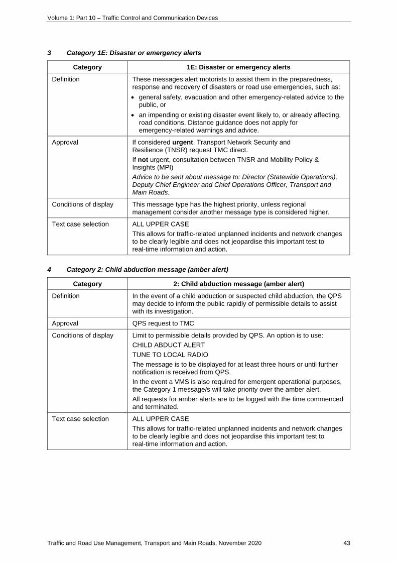
3 Category 1E: Disaster or emergency alerts
Category 1E: Disaster or emergency alerts
Definition These messages alert motorists to assist them in the preparedness, response and recovery of disasters or road use emergencies, such as:
• general safety, evacuation and other emergency-related advice to the public, or
• an impending or existing disaster event likely to, or already affecting, road conditions. Distance guidance does not apply for emergency-related warnings and advice.
Approval If considered urgent, Transport Network Security and Resilience (TNSR) request TMC direct.
If not urgent, consultation between TNSR and Mobility Policy & Insights (MPI)
Advice to be sent about message to: Director (Statewide Operations), Deputy Chief Engineer and Chief Operations Officer, Transport and Main Roads.
Conditions of display This message type has the highest priority, unless regional management consider another message type is considered higher.
Text case selection ALL UPPER CASE
This allows for traffic-related unplanned incidents and network changes to be clearly legible and does not jeopardise this important test to real-time information and action.
4 Category 2: Child abduction message (amber alert)
Category 2: Child abduction message (amber alert)
Definition In the event of a child abduction or suspected child abduction, the QPS may decide to inform the public rapidly of permissible details to assist with its investigation.
Approval QPS request to TMC
Conditions of display Limit to permissible details provided by QPS. An option is to use:
CHILD ABDUCT ALERT
TUNE TO LOCAL RADIO
The message is to be displayed for at least three hours or until further notification is received from QPS.
In the event a VMS is also required for emergent operational purposes, the Category 1 message/s will take priority over the amber alert.
All requests for amber alerts are to be logged with the time commenced and terminated.
Text case selection ALL UPPER CASE
This allows for traffic-related unplanned incidents and network changes to be clearly legible and does not jeopardise this important test to real-time information and action.

Volume 1: Part 10 – Traffic Control and Communication Devices
Traffic and Road Use Management, Transport and Main Roads, November 2020 44
5 Category 3: Traffic management information
Category 3: Traffic management information
Definition These messages indicate the location and degree of localised recurrent congestion, directional signage and travel times.
Approval TMC
Conditions of display These messages will be replaced by incident and other category messages if regional management consider another message type is considered higher.
Text case selection Upper and Lower Case
Upper and lower case with capital letters at the start of each word on VMS where systems allow for this to occur.
This allows for the necessary distinction between critical messages and lower-order (non-critical) message types.
6 Category 4: Planned roadworks and special events messages
Category 4. Planned roadworks and special events messages
Definition These messages provide advanced information of special events or planned roadworks, which have an ability to affect traffic (generally including a description and date / time of the event, expectation of delay and/or suggestion to consider alternative routes).
Approval TMC
Conditions of display These messages will be replaced by incident and other category messages if considered of higher importance.
For special events, advance information should only be displayed up to one week before the start of the event.
Wherever possible, generic descriptors of sporting events will be used when companies have purchased naming rights. Avoid advertising.
Text case selection Upper and Lower Case
Upper and lower case with capital letters at the start of each word on VMS where systems allow for this to occur.
This allows for the necessary distinction between critical messages and lower-order (non-critical) message types.
Volume 1: Part 10 – Traffic Control and Communication Devices
Traffic and Road Use Management, Transport and Main Roads, November 2020 45
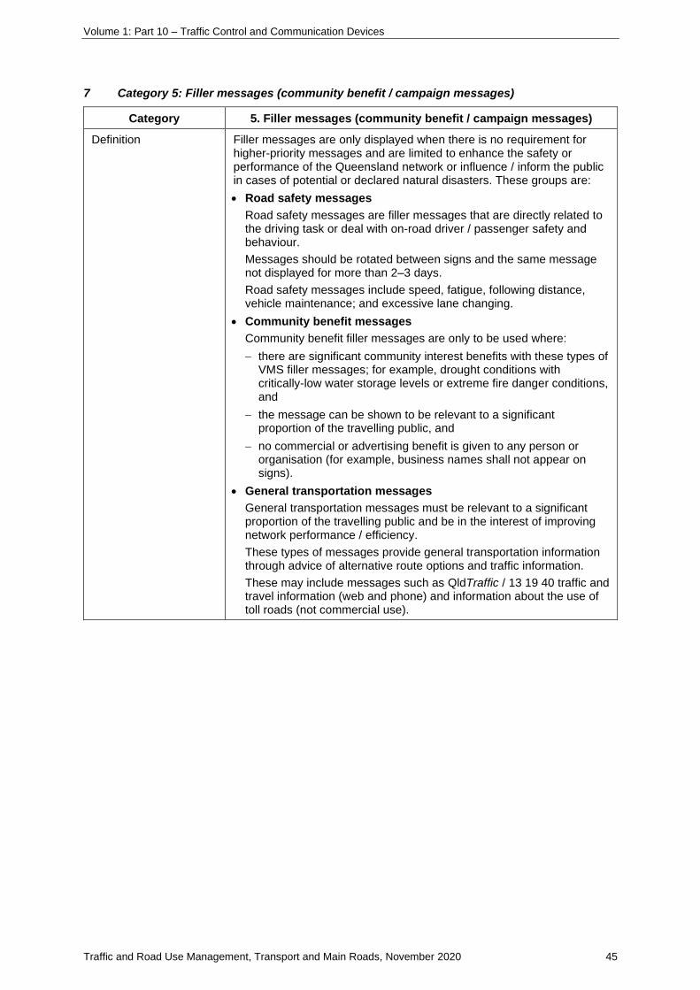
7 Category 5: Filler messages (community benefit / campaign messages)
Category 5. Filler messages (community benefit / campaign messages)
Definition Filler messages are only displayed when there is no requirement for higher-priority messages and are limited to enhance the safety or performance of the Queensland network or influence / inform the public in cases of potential or declared natural disasters. These groups are:
• Road safety messages
Road safety messages are filler messages that are directly related to the driving task or deal with on-road driver / passenger safety and behaviour.
Messages should be rotated between signs and the same message not displayed for more than 2–3 days.
Road safety messages include speed, fatigue, following distance, vehicle maintenance; and excessive lane changing.
• Community benefit messages
Community benefit filler messages are only to be used where:
− there are significant community interest benefits with these types of VMS filler messages; for example, drought conditions with critically-low water storage levels or extreme fire danger conditions, and
− the message can be shown to be relevant to a significant proportion of the travelling public, and
− no commercial or advertising benefit is given to any person or organisation (for example, business names shall not appear on signs).
• General transportation messages
General transportation messages must be relevant to a significant proportion of the travelling public and be in the interest of improving network performance / efficiency.
These types of messages provide general transportation information through advice of alternative route options and traffic information.
These may include messages such as QldTraffic / 13 19 40 traffic and travel information (web and phone) and information about the use of toll roads (not commercial use).

Volume 1: Part 10 – Traffic Control and Communication Devices
Traffic and Road Use Management, Transport and Main Roads, November 2020 46
Category 5. Filler messages (community benefit / campaign messages)
Application Applicants can request a copy of the Filler Message Request Form (F4974) and quick reference guide by:
• contacting [email protected]; or.
• internal applicants can access this form through corporate forms database.
For further assistance or to submit the completed application, email [email protected]
On receipt of the completed application, it will be assessed, and response provided.
Before submitting, the applicant must ensure the following message conditions are met:
• it clearly falls into one of the three message groups outlined in the definition section; and
• is short, clear and concise as not to distract road users from their primary driving tasks; and
• kept within one screen and within the character limitations; and
• it is constructed to meet the requirements of Section 5.4-1 Variable message sign statements outlined in this supplement.
Please note, that due to the conditions of display placed on filler messages and
number of requests, no guarantee can be made that they will be displayed and
for what period of time.
Approval Mobility Policy and Insights Unit (Road Operations, E&T)
If it is a ‘road safety message’ request, approval is also required by Community Road Safety (Road & Rail Safety, CSSR).
Conditions of display The following limitations apply to the use of filler messages:
• Filler messages must not be displayed during peak periods (peak is generally 6:00–9:00 am and 3:00–6:00 pm, Monday to Friday, but can vary depending on regional traffic conditions) as the VMS shall only be used for incident and traffic management purposes during peak period times.
• Filler messages must not be displayed when the traffic flows in the direction relevant to the VMS device are greater than 85% of the road capacity and are only to be used on devices programmed through STREAMS.
• Filler messages must be displayed for a minimum of 20% and not exceed more than 30% of the available time. Road safety messages shall account for at least half of the filler messages being displayed.
• Limiting the display of filler messages to not more than 30% of off-peak times shall reduce the risk of frequent exposure to non-critical information leading to VMS messages being ignored. At all other times, the VMS will be blank or in 'exercise' mode, with displays of wording of hazards, conditions and/or traffic management information.
Text case selection Upper and Lower Case
Upper and lower case with capital letters at the start of each word on VMS where systems allow for this to occur.
This allows for the necessary distinction between critical messages and lower-order (non-critical) message types.

Volume 1: Part 10 – Traffic Control and Communication Devices
Traffic and Road Use Management, Transport and Main Roads, November 2020 47
5.3.2 Abbreviations
5.3.2-1 Abbreviations – Queensland
See Appendix C-1 for approved Queensland-specific variants on national guidance for abbreviations
for use on variable message signs.

Volume 1: Part 10 – Traffic Control and Communication Devices
Traffic and Road Use Management, Transport and Main Roads, November 2020 48
5.4 Message content and format
5.4-1 Variable message sign statements
See Appendix D-1 for approved Queensland-specific variants on national guidance for variable
message signs problem statements.
See Appendix E-1 for approved Queensland-specific variants on national guidance for generic
messages.

Volume 1: Part 10 – Traffic Control and Communication Devices
Traffic and Road Use Management, Transport and Main Roads, November 2020 49
5.6 Applications of Variable Message Signs
5.6.9 Vehicle activated intersection and road geometry signs
5.6.9-1 Bicycle activated warning signs
1 Purpose and scope of this section
Road treatments to improve operational safety for cyclists at hazards (such as road or bridge
carriageway narrowings or sightline restricted locations ‘blind spots’) have, to date, taken the form of
Bicycle Awareness Zones (BAZ), which use road pavement markings and associated signage to
highlight the possible presence of cyclists.
Research1 undertaken by the Department of Transport and Main Roads has demonstrated the
effectiveness of the BAZ treatment at various narrow road lanes in Queensland; however, these
permanent static hazard warning signs and pavement markings may lose credibility if the location is
infrequently used by cyclists, to the point that motorists who use a location regularly may not be
expecting to see cyclists. This can result in the treatment being ignored or disregarded by impatient
drivers, particularly in situations such as lengthy two-lane bridges or stretches of narrow roads. The
installation of dynamic signage, in the form of bicycle- or cyclist-activated electronic signs, is an
additional measure which may improve driver awareness and reduce operational risks for all road
users at high-risk squeeze point locations.
The 2013 Transport and Main Roads commissioned-AARB study Innovative Treatment for Pinch
Points reviewed current practice in Australia and New Zealand (where dynamic cyclist warning
signage is in use). In this study, bicycle-activated hazard warning signs were trialled at eight narrow
bridge locations already fitted with BAZ markings. Qualitative benefits (such as user perception) were
observed during the trials and a perception survey was undertaken to evaluate the installations.
Though attempts were made to measure the immediate effects of installations, the wide range of
behaviours observed, and lateral overtaking distance measured, did not enable a robust quantification
of benefits. Based on these trials, the study recommended that these devices be used sparingly as
additional enhancements in high-risk locations, that their installation be closely monitored, and that
advice be developed. The implementation of these devices is only recommended if it meets the use
application qualifications detailed following.
This section should be read in conjunction with the following:
• Austroads Guide to Road Design Part 3 Geometric Design, Section 4.8 Bicycle Lanes
• Austroads Cycling Aspects of Austroads Guides, Section 4.2 Key Design Criteria and
Considerations
• NZ Transport Agency P32 Notes for Electronic Warning Signs on State Highways
• NZ Transport Agency P32 Specification for Electronic Warning Signs on State Highways
• Queensland Department of Transport and Main Roads, Traffic and Road Use Management
manual, Volume 1 Part 10 Section 6.5-1 Bicycle Awareness Zones
1 Munro 2011, Evaluation of narrow bridge treatments for cyclist safety: final report, prepared by Sinclair Knight Merz, Transport and Main Roads, Brisbane, Queensland.

Volume 1: Part 10 – Traffic Control and Communication Devices
Traffic and Road Use Management, Transport and Main Roads, November 2020 50
• Queensland Department of Transport and Main Roads, Traffic and Road Use Management
manual, Volume 3 Part 5 Design Guide for Roadside signs
• Queensland Department of Transport and Main Roads, Queensland Manual of Uniform Traffic
Control Devices, Part 9 Bicycle Facilities
• Queensland Department of Transport and Main Roads Technical Note TN160 Vehicle
Activated Signs
• Charlton, SG & Baas, PH 2006, Assessment of hazard warning signs used on New Zealand
roads, research report 288, Land Transport New Zealand, Wellington, NZ.
• Koorey, G, Planning & Design for Cycling – SIGN OF THE TIMES,
http://can.org.nz/system/files/Design-0504-WarningSigns.pdf
• Munro, C 2011, Evaluation of narrow bridge treatments for cyclist safety: final report, prepared
by Sinclair Knight Merz, Transport and Main Roads, Brisbane, Qld
• Winnett, MA & Wheeler, AH 2002, Vehicle-activated signs: a large-scale evaluation, report
TRL548, Transport Research Laboratory, Crowthorne, UK (TMR 2013).
2 Purpose of active warning signs
Bicycle activated warning signs (BAWS) can be installed as an interim treatment to alert motorists to
the risk of encountering cyclists on a hazardous section of road. They are only for use where the
standard reflectorized warning signs and pavement marking have been tried and found not to be
sufficiently effective in warning drivers to modify their behaviour so that cyclists can safely negotiate
the hazard(s). These traditional warning signs and pavement markings are especially likely to be
ignored if cyclists are relatively rare, such as on rural routes with fewer than 100 cyclists a day.
BAWS, when used, are intended to meet the following objectives:
• to highlight and draw drivers’ attention to the presence of cyclists on the road, and
• to reinforce driver expectation of, and engender correct responses to, the hazard depicted by
the sign.
BAWS can be an additional positive safety measure at hazardous locations when implemented in
conjunction with traditional pavement markings and signage. This type of device can greatly improve
credibility and awareness of existing signs and markings, by only activating when a cyclist is present.
BAWS must only be used as a supportive measure to increase awareness of the risks and to support
already installed or co installed signs and pavement markings. They must not be installed on their
own.

Volume 1: Part 10 – Traffic Control and Communication Devices
Traffic and Road Use Management, Transport and Main Roads, November 2020 51
Figure 2 – Standard warning signs and pavement markings treatment options
3 When should bicycle activated warning signs be used?
BAWS may be considered as a retrofit advisory treatment in addition to standard warning signage and
pavement marking, used to supplement, but not intended to replace them. BAWS must only be used
as a treatment of last resort, after:
• an evaluation of existing treatments has shown them to be ineffective
• the risks (as outlined in this document) have been considered, and
• there is commitment to ongoing maintenance requirements.
It is only appropriate to use BAWS at locations where:
• there is a permanent feature of the road that is a hazard (especially one that is not obvious or
apparent to the driver of a motor vehicle), and
• where cyclists are infrequent (or present only at irregular times of the day).
Historically, these signs have been installed at high risk locations, where the road width or space is
constrained due to road design / layout which continues for some distance (such as on narrow bridges
and viaducts) causing concerns for safety of cyclists using the area. Examples (shown at Figure 3)
include:
• on narrow (lane width <3.5 m) bridges as a supplement to sign TC9700 NO OVERTAKING
BICYCLES ON BRIDGE (see Figure 6(B)
• bicycle path priority crossing across local roads and on adjacent side roads with limited
visibility from the road of the crossing (in advance of the intersection or path)
• on a sight-restricted crest or curve with a narrow (width <3.5 m) lane or a steep descent, and
• in advance of a tunnel, narrow or winding road system with restricted passing space.

Volume 1: Part 10 – Traffic Control and Communication Devices
Traffic and Road Use Management, Transport and Main Roads, November 2020 52
BAWS have a supplementary purpose and must not be used to replace a primary static sign warning
of the hazard – that is, all standard primary (static) signage must be in place before a BAWS can be
installed as secondary signage.
Figure 3 – Examples of applications of use for the active warning signs
Note: The sign examples are from overseas and hence any similar signs installed in Queensland must meet
MUTCD and TC requirements.
4 Risks associated with bicycle activated warning signs
Before a decision is made to install and operate a BAWS, there are several risks that are unique to
this type of signage (that are not risks for standard signage). These risks must be carefully considered,
and countermeasures must be put in place.
Risk of ‘conditioning’ the driver
The intent of these signs is that they will only activate when a cyclist is present in the ‘hazardous’
section of road, to inform motorists of the presence of cyclists and the need to alter their driving
behaviour. The inherent risk of installing such a system is that drivers may become ‘dependant’ upon
the sign activating to inform them of the presence of a cyclist. If motorists do become conditioned in
this way, there is a risk that if the sign malfunctions or is damaged / vandalised then they will not
expect to see the cyclist.

Volume 1: Part 10 – Traffic Control and Communication Devices
Traffic and Road Use Management, Transport and Main Roads, November 2020 53
Risk of lack of activation
The sign must also be activated by cyclists by either a push button or cycling over a pavement bicycle
detector. If the detector or push button are not properly maintained and are repeatedly out-of-order,
this will affect user confidence and acceptance of the system. In some instances, there is a risk that,
even once repaired, cyclists may fail to activate the sign. If a cyclist deliberately fails to activate the
sign, then the credibility of the sign will be damaged, and it will be ignored.
Need for continual monitoring and maintenance
Research on similar systems (school zone flashing lights) has shown that hardware reliability is a
major issue, particularly if the system to be installed does not have an inbuilt electronic
‘report-fault-to-base’ capability. As a result, there is a need for a dedicated maintenance program to
ensure the sign is continually operational and to have maintenance systems in place. If the system
does not have an inbuilt electronic ‘report-fault-to-base’ capability, then information must be provided
on site (such as a toll-free phone number to contact) to allow for prompt repairs. If batteries are used
as part of the system, they must be checked and replaced as part of the regular maintenance
program.
Risk of electrical failure
When compared with static warning signage, the life of active warning signage is considerably shorter
due to the inevitable deterioration of electrical components and exposure to the elements. In addition
to regular maintenance, plans must be made to replace the signage in line with the manufacturers’
information on the expected life of the product. Mains power may be difficult to obtain in isolated
locations. If solar powered, battery backup will be essential for cloudy days.
Risk of mechanical failure
If the bicycle detector is using an ‘in pavement’ detector (such as an induction loop), there will be a
risk of damage of equipment from road resealing or pavement rehabilitation works. Coordination with
the asset manager will be essential.
Risk of vandalism and theft of components
A case study from New Zealand highlighted the risk of deliberate vandalism and theft of high-value
electrical components. In this case, a pair of solar-powered BAWS installed on a 300 m-long bridge
was stolen twice (the entire pole was cut down). At the same site, due to the prominence of the sign,
they were also shot at with a shotgun, which required the replacement of the full door assembly and
electronics on both signs.
5 When are bicycle activated warning signs not suitable?
BAWS are not suitable treatments:
• in locations where there are large numbers of cyclists (regular presence on the road)
• in greenfield applications – higher order bicycle facilities such as bicycle lanes and paths
should always be provided in newly developing areas

Volume 1: Part 10 – Traffic Control and Communication Devices
Traffic and Road Use Management, Transport and Main Roads, November 2020 54
• where bicycle lanes are achievable through minimal infrastructure works (for example, lane
width reallocation after resurfacing program)
• as a wayfinding device or ‘gap filling’ in mixed off road / on road routes, and
• on roads with an AADT greater than 20,000 vehicles per day in one direction and/or more than
two lanes in each direction.
The BAWS treatment is used primarily as a warning symbol but must be used sparingly and limited to
specific conflict / danger points.
6 Signage specification
Active warning signs are discrete signs, which remain blank until activated by an approaching bicycle.
Signs shall be operational only when cyclists are present in the hazard zone. Activation should be by
means of bicycle-sensitive induction loops. A separate signed manual activation button is also
recommended to build cyclist confidence in the system’s operational capacity (see Figure 6(B)).
The display size must be comparable with the static sign for that speed environment, with larger sizes
required in higher speed environments.
Supplementary plates must be used in conjunction with the particular sign to indicate the condition that
is in place when the lights flash, for example:
• (BICYCLES) ON BRIDGE
• (BICYCLES) ON ROAD
• (BICYCLES) IN TUNNEL.
BAWS must always be installed in conjunction with an approved TC or MUTCD sign displaying the
appropriate message relative to the hazard (see Figure 6(A)). For an approved example of an active
warning sign, refer to TC sign TC1921.

Volume 1: Part 10 – Traffic Control and Communication Devices
Traffic and Road Use Management, Transport and Main Roads, November 2020 55
Figure 6(A) – Examples of bicycle activated warning signs that replicate MUTCD requirements
The left sign uses LED displays. The right sign uses alternating flashing lights and static warning
signs. For an approved example of an active warning sign, refer to TC sign TC1921.
Frangible sign supports must also be used to minimise the risk of a serious injury to vehicle
occupants, should a collision occur. The use of the slip base mechanism on the signpost is a better
alternative than the construction of a barrier to protect a stiffer post or sign support.
Figure 6(B) – Layout of sign assembly and detector loops
Note: This figure does not show the required static sign associated with the flashing warning sign and the sign
example is from overseas, hence any similar signs installed in Queensland must meet MUTCD and
TC requirements.

Volume 1: Part 10 – Traffic Control and Communication Devices
Traffic and Road Use Management, Transport and Main Roads, November 2020 56
Figure 6(C) – United States’ examples of bicycle activated warning signs
Note the use of supplementary plates to indicate the presence of cyclists. The sign examples are from overseas
and hence any similar signs installed in Queensland must meet MUTCD and TC requirements.
Figure 6(D) – Active warning sign on a narrow winding road near Steamboat, Colorado
Figure 6(E) – Mad River Bridge, California

Volume 1: Part 10 – Traffic Control and Communication Devices
Traffic and Road Use Management, Transport and Main Roads, November 2020 57
Figure 6(F) – Arch Cape Tunnel, Oregon
7 Site assessment and selection process
Before making a decision to install a BAWS, it is important to undertake an audit of existing road
furniture, fixed signs, road condition and road markings to assess their standard and condition. A
BAWS must only be deployed when it is clear that the problem cannot be remedied by improving the
existing static signing and/or line marking.
Selecting a site
The aim of the installation of BAWS is to enhance driver awareness of a hazard ahead, but some sites
may not be suitable. A recent evaluation of the performance of (motor) vehicle activated signs (VAS)
in Queensland found that the signs generally do not perform well2:
• on roads with high volume of traffic – it is generally not recommended to install a VAS on
roads with an AADT greater than 20,000 vehicles per day in one direction (this figure was
determined for roads with two lanes in each direction)
• on roads with a speed limit equal to or greater than 100 km/h (the signposted speed limit may
be reduced in advance of the hazard and a VAS installed)
• on roads with more than two lanes in each direction
• on approaches with vertical or horizontal curves or gradients (external radars may be more
effective on some such approaches)
• on roads with a high percentage of heavy vehicles (that may result in the sign frequently being
obscured by the slower moving vehicles)
• in areas with a dense canopy of trees (option to locate solar panel remotely)
• on roads with a limited forward visibility (for example, due to road geometry), and
• on roads with an overtaking lane (speeding vehicles are often obscured by larger vehicles on
the nearside lane).
2 Vehicle Activated Signs Operational Guidelines (under development), Queensland Government, 2012

Volume 1: Part 10 – Traffic Control and Communication Devices
Traffic and Road Use Management, Transport and Main Roads, November 2020 58
These issues will be similar for BAWS and therefore site assessments are required. Table 7(A) details
the key evaluation components of sites, and the installation of these signs.
Table 7(A) – Site assessments for Bicycle Activated Warning Signs 3
Criteria Considerations
Crash history Review crashes that have occurred at the location related to cyclists. Did vehicles wanting to overtake cyclists in narrow space cause the crashes? Where there is limited crash history, site observations of behaviours should be considered.
Posted speed limits
Wherever possible, conduct a speed survey at the proposed location to establish what the speed of traffic is and whether there is a problem with vehicles travelling at inappropriately high speeds.
Traffic volumes Traffic volumes must be below 20,000 vehicles per day in one direction.
Site geometry BAWS are most effective on a straight, level road; however, signs with external radars may be implemented on approaches with vertical or horizontal curves or gradients, providing there is a clear sight line between the driver and the sign, so the driver can be exposed to the sign message for at least three seconds. If the road geometry prevents these criteria being met with an external radar, the site is not suitable for treatment with BAWS. BAWS must be placed on roads with only one lane in each direction.
Positioning of the sign
In addition to standard signage practice, consideration should be given to the following requirements:
Cyclist activation of the sign
• What is the likely path of the cyclist(s)?
• Is the likely path of cyclist(s) clear of parking spaces, driveways or other property access
points?
• Is the bicycle detector type suitable for the application? (for example: for an exclusive bicycle
lane approach to the pinch point, a more sensitive detector can be used, whereas a narrow
lane with mixed traffic will require a detector that can distinguish between bicycles and motor
vehicles).
Operation of the sign
• Is the sign clear of vegetation that could potentially affect the operation of the solar panels?
• Does the installation location have sufficient sunlight for solar panels to charge the batteries
for the predicted number of actuations?
• Is the mounting height sufficient to optimise visibility and reduce the risks of vandalism?
• Is there any existing infrastructure requiring modifications? (for example, parking spaces, no
stopping lines).
3 Content sourced from Vehicle Activated Signs Operational Guidelines (under development), Queensland Government, 2012.

Volume 1: Part 10 – Traffic Control and Communication Devices
Traffic and Road Use Management, Transport and Main Roads, November 2020 59
Visibility of the sign
• Is the sign suitably visible to minimise potential conflict with existing signs? Is there a risk it will
be lost in the signage clutter?
• Is the signage clear of vegetation that may obscure the visibility of the sign?
The site needs to be assessed to ensure the appropriate placement of the sign can occur before
implementation. Operation and ongoing maintenance of the sign should also be considered; see
Table 7(B) for further details.
Table 7(B) –Bicycle Activated Warning Signs: placement and operation
Criteria Considerations
Sign placement • Sign must be clearly visible and not obscured by trees, shrubs or other signs (now and into the future).
• There must be no overhanging trees to obscure the solar panel.
• Signs should not be located under power lines but, if this cannot be avoided, there must be sufficient clearance between the top of the signs and the power cables.
• Signs must be located on a straight, level approach where possible to ensure there is enough time for the radar to detect the cyclist and to display an appropriate message.
• Other factors that may affect the function of any sign and should be considered include locations of driveways, parking bays, vegetation obstruction, and other conflict zones that may impede driver’s view of the sign or otherwise interfere with the sign’s radar operation.
• Signs shall be placed at, or immediately prior to, the hazard zone. There must be a static sign warning of the hazard (for example, narrow bridge, tunnel ahead, road narrows) before the BAWS, which should be placed between the static sign and the hazard.
• Activation should be sensors placed where cyclists will reliably activate them. A separate signed manual activation button is also recommended to build cyclist confidence in the system’s operational capacity. The manual activation button must be lit so it is visible for night-time operation.
Lateral placement and mounting height
The lateral placement of a BAWS must be determined in accordance with MUTCD Part 1 Sections 12.3.2
Similarly, the mounting height of BAWS must be determined in accordance with MUTCD.
Operation The sign LED colours must replicate the sign display (design and colour) in the MUTCD or TC as closely as possible (but with black background). The intensity of the LEDs should be able to be adjusted according to different light conditions (including night-time activation). When the sign is not activated, it must remain blacked out.
The sign must be programmed so, if there is a malfunction, the sign should remain blank / blacked out.
Sign display Signs must conform with the MUTCD or TC sign designs (design and colour must be replicated) and must not contain any non-standard pictograms or messages.

Volume 1: Part 10 – Traffic Control and Communication Devices
Traffic and Road Use Management, Transport and Main Roads, November 2020 60
Criteria Considerations
Sign support To maintain the forward visibility of a BAWS, it may be necessary to place the installation within the clear zone. While the speed reducing feature of a BAWS is likely to reduce the likelihood of a crash, placing the sign in the clear zone increases the risk of an errant vehicle colliding with the BAWS support. If the sign is placed in the clear zone, frangible sign supports must be used to minimise the risk of a serious injury to vehicle occupants, should such a collision occur. The use of the slip base mechanism on the signpost is a better alternative than the construction of a barrier to protect a stiffer post or sign support.
Maintenance A regular maintenance program is essential for these signs. Back to base monitoring or remote alert technology should be included in the sign design to improve operational reliability. If the system does not have an inbuilt electronic ‘report fault to base’ capability, then information must be provided on site (such as a toll-free phone number to contact) to allow for prompt repairs.
8 Case studies
Figure 8(A) – Narrow bridge treatments in Marlborough and Arthur, New Zealand
Note: The sign examples in this image are from overseas; any similar signs installed in Queensland must meet
MUTCD and TC requirements.
Flashing LED warning signs have been installed in various parts of urban and rural New Zealand since
2009. A number of these signs have been located on busy rural roads on the approaches to narrow
two-lane bridges. The first of these signs at Appleby in the north of New Zealand’s South Island was
mains powered. Units subsequently installed have been solar-powered.
The unit pictured is on State Highway 1 at the bridge across Wairau River between Spring Creek and
Tuamarina in the Marlborough district. It is powered by a solar panel. This unit is in a remote location
and has been subject to theft and vandalism attacks on three occasions since its installation in 2011.
The installation consists of a cyclist activated sign panel at each end of a 300 m long river bridge.
Each sign is powered by its own solar panel. The signs are triggered by cyclists riding over bicycle
detection loops located in the roadway adjacent to the signs. In June 2011, new loops were put into
the pavement approximately 20 m before each sign so that, as the cyclist rides over the loops, he or

Volume 1: Part 10 – Traffic Control and Communication Devices
Traffic and Road Use Management, Transport and Main Roads, November 2020 61
she will be able to see the sign light up and know that the sign is on. These trigger the sign to display
for approximately 1 minute 45 secs (enough time for a cyclist to get across the bridge).
The sign is manufactured by HMI Technologies and the loop detector circuitry is made by Eco counter
with Zelt Inductive Loops.
The batteries inside the sign and the loop detector circuitry need to be checked and replaced with a
regular maintenance program. Approximate battery life expectancies are one year for the batteries in
the Eco counter circuitry and three years for the HMI sign panel.
The first systems to be installed lacked built in remote alert features which reduced reliability. The
newer systems have this technology included in the sign.
Other systems have been installed in different locations, some to warn road users on narrow sections
of roadway without a sufficient shoulder. A solar powered hazard sign has been installed in Auckland
City for $60,000 at the intersection of Tamaki Drive and Ngapipi Road east of central Auckland.
A cyclist-activated flashing LED panel associated with a static warning sign is activated when
citybound (westbound) cyclists approach the intersection. The purpose of the signage is to warn
eastbound motorists queuing to turn right at the intersection into Ngapipi Road that cyclists are
approaching from the opposite direction.
The council's transport committee decided to install the sign as a trial after 12 cyclists were injured in
crashes at the intersection over five years, making it the city's second worst black spot for cyclists.
Figure 8(B) – Narrow roadway (no shoulder), Rocky Point, Washington USA
Note: The sign examples in this photo are from overseas; any similar signs installed in Queensland must meet
MUTCD and TC requirements.

Volume 1: Part 10 – Traffic Control and Communication Devices
Traffic and Road Use Management, Transport and Main Roads, November 2020 62
This flashing-beacon system was installed at Rocky Point on State Route 150 between Chelan and
Manson in Washington State, northwest USA. The solar powered yellow flashing lights are
automatically triggered when a bicycle passes, alerting drivers to the signs between the beacons that
say, ‘narrow shoulder’ and ‘watch for bikes’.
The project originated in July 2011 when Washington State Department of Transport (WSDOT) was
contacted by a Manson resident concerned about the increase in vehicle and bicycle traffic on the
highway during the summer tourism season. During the next two years, WSDOT analysed collision
data and conducted outreach efforts that generated feedback from residents and a variety of user
groups confirming the need.
WSDOT determined flashing beacons were the best alternative; however, bringing power to the site
was cost prohibitive. Eventually, a solar panel system combined with a seasonally scheduled daily
timer was developed. The next issue to resolve was the detection system. Current WSDOT bike
beacons are manually activated by the rider; this one detects bikes with a radar system that
differentiates between bicycles, pedestrians and motorcycles.
Engineers completed final design and plans, a contractor was selected, and the new flashing beacon
pole was fabricated before installation and testing, and final adjustments were complete before the
US$16,000 system went into service.
Feedback from drivers and riders during the initial operational period has been positive. If the system
proves successful, WSDOT will consider other remote locations for installation.
Figure 8(C) – Narrow bridge (no shoulder), Noosa Parade, Munna Point Bridge, Noosa Heads,
Australia
Note: The sign examples were based on a trial and hence any similar signs installed in Queensland must meet
MUTCD and TC requirements.

Volume 1: Part 10 – Traffic Control and Communication Devices
Traffic and Road Use Management, Transport and Main Roads, November 2020 63
The BAWS trial is located at two narrow bridges along Noosa Parade in Noosa Heads – the Munna
Point Bridge and the Sheraton Bridge. The bridges are approximately 120 m and 60 m long
respectively and very narrow (6.5–7.5 m in width). In addition, as can be seen in the photo provided,
the Munna Point Bridge is located on a hill with the crest halfway along the bridge, creating a potential
hazard as motorists often cannot see cyclists on the bridge over the crest. The BAWS operate with an
on-route detection loop and have solar panel operation. BAZs also exist on both bridges.
Sunshine Coast Regional Council had experienced a large number of customer complaints at Munna
Bridge on Noosa Parade when the BAZ pavement markings were installed. The number of complaints
reduced when additional signs were installed to supplement the BAZ markings. There had also been a
number of pinch point related crashes at both locations. Council proposed a trial of BAWS at the two
bridges.
Surveys undertaken at the trial locations observed vehicles slowing down significantly prior to
overtaking a cyclist, when the dynamic sign was activated. Early braking was also employed by drivers
once the dynamic sign was activated even when cyclists were not visible to drivers. Drivers also gave
cyclists ample room when overtaking on the bridge, including crossing the double lines to do so. It is
noted that Queensland legislation requiring motorists to leave 1–1.5 m clearance when overtaking
cyclists legally permits crossing the double lines, providing it is safe to do so. The treatment also had
positive influences on cyclists’ perceptions of safety.
Due to the relatively low cost of installing BAWS compared with a full infrastructure upgrade, it is
logical to consider them as the next level of treatment for high traffic volume and high cyclist demand
locations with physical constraints and engineering challenges, for example, high bridge widening
costs.
Volume 1: Part 10 – Traffic Control and Communication Devices
Traffic and Road Use Management, Transport and Main Roads, November 2020 64
5.7 Electronic speed limit signs
5.7-1 Guidelines for the permanent placement of variable speed limit and lane control
signs for motorways, long bridges and tunnels
1 Introduction
This supplement defines the placement and mounting requirements for variable speed limit (VSLS)
and variable speed limit and lane control signs (VSL / LCS) on motorways, long bridges and in
tunnels.
2 Scope
2.1 In scope
This supplement defines the requirements for VSLS and VSL / LCS necessary to implement a variable
speed limit zone and lane control on motorways, long bridges and in tunnels. This supplement defines
the placement of electronic variable speed limit signs as described in the Queensland Manual of
Uniform Traffic Control Devices (MUTCD) Part 4 Speed controls.
This supplement defines the requirements for the permanent:
i) placement of VSLS and VSL / LCS, and
ii) mounting arrangements for VSLS and VSL / LCS.
This supplement shall be read in conjunction with all relevant technical standards – in particular, the
technical standard for Provision of Variable Speed Limit and Lane Control Signs (MRTS206).
2.2 Out of scope
This supplement does not define the placement of static variable speed limit signs (for example,
school zones) and changing message variable speed limit signs as described in MUTCD Part 4 Speed
Controls.
This supplement does not define the placement of electronic VSLS or VSL / LCS for:
i) arterial roads (including school zones and other special speed zones), and
ii) work zones. Refer to MUTCD Part 3 Works on roads and the Traffic and Road Use
Management manual and relevant Supplements for the use of permanent variable speed limit
and lane control signs in construction and maintenance work areas on motorways.
This supplement does not define the placement of:
i) lane control for the purposes of tidal flow, and
ii) dynamic lane use signs for the purpose of designating special purpose lanes: that is, transit
lanes.
This supplement does not define the procedure for determining the maximum posted speed limit of a
road. Refer to Manual of Uniform Traffic Control Devices (MUTCD): Part 4 Speed controls.

Volume 1: Part 10 – Traffic Control and Communication Devices
Traffic and Road Use Management, Transport and Main Roads, November 2020 65
2.3 References
The following documents should be considered in conjunction with this document.
• The Queensland Manual of Uniform Traffic Control Devices (MUTCD), and
− Part 1 General information and sign illustration
− Part 3 Works on roads
− Part 4 Speed controls
− Part 14 Traffic signals
• Traffic Control (TC) signs
• Transport and Main Roads Technical Specification MRTS206 Provision of Variable Speed
Limit and Lane Control Signs
• Road Planning and Design Manual (2nd edition) Vol. 5 Intelligent Transport Systems
• Transport and Main Roads’ ITS Placement Guideline
• Transport and Main Roads’ Engineering Policy EP149 Managed Motorways
• Austroads Guide to Smart Motorways.
For further details, please contact Director (Active Network Operations) in Engineering and
Technology Branch.
3 Background
3.1 Variable speed limit zones
A VSL zone may be applied on a motorway, long bridge or in a tunnel to allow a reduction in the
posted speed limit at times when road safety and performance are compromised, and where fulltime
lower static speed limits are inappropriate. The variable speed limit zone is implemented through the
use of VSLS and selected static signs.
The main objectives of a VSL zone are to control the posted speed limit within the zone to:
i) manage the operating speed and, thus, optimise the traffic flow rates by reducing the
probability of flow breakdown and congestion
ii) if congestion occurs, manage the operating speed of traffic approaching and departing the
congestion to restore the optimal flow rate as quickly as practicable
iii) reduce the likelihood of traffic crashes (especially secondary crashes) by reducing the speed
of vehicles as they approach an incident, traffic queue or stoppage
iv) reduce the speed differentials between mainline traffic and entrance ramp traffic to improve
safety and help prevent traffic flow breakdown
v) minimise the potential risk of injury to the public and emergency personnel at incidents or
workers during maintenance / construction by reducing the speed limit approaching and
passing through the site, and
vi) manage safety during poor weather or road conditions by reducing the speed limit to an
appropriate speed for the prevailing conditions.
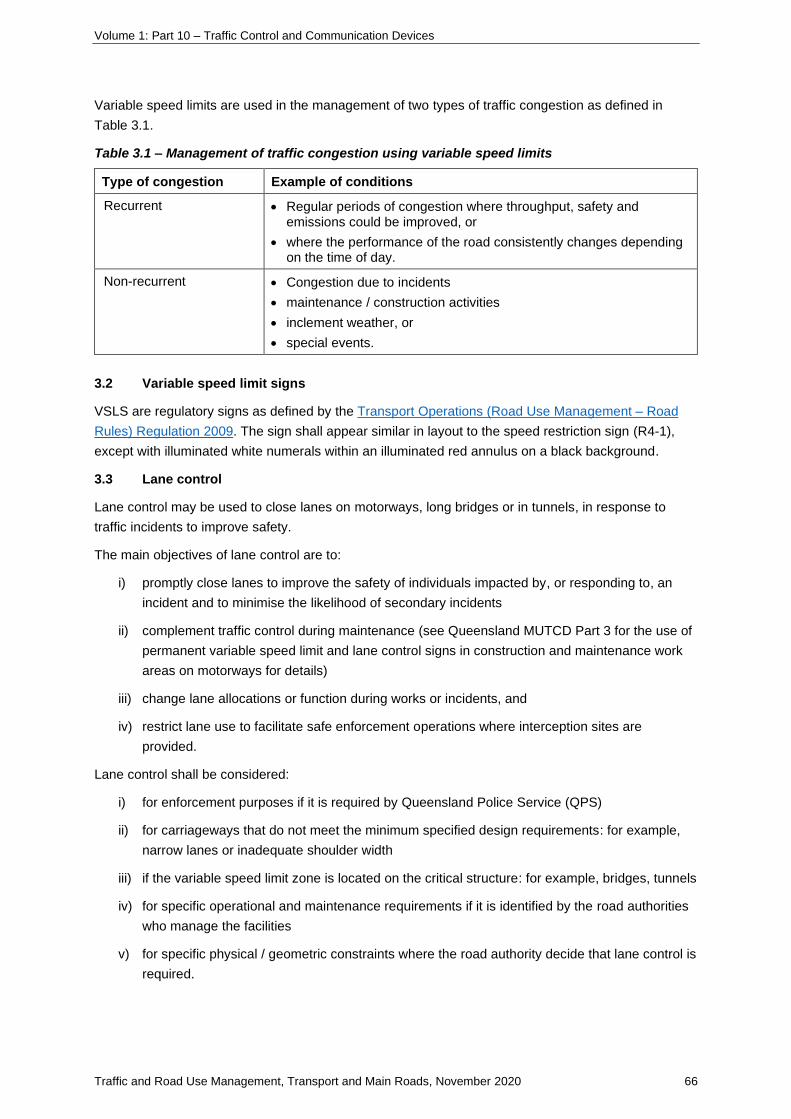
Volume 1: Part 10 – Traffic Control and Communication Devices
Traffic and Road Use Management, Transport and Main Roads, November 2020 66
Variable speed limits are used in the management of two types of traffic congestion as defined in
Table 3.1.
Table 3.1 – Management of traffic congestion using variable speed limits
Type of congestion Example of conditions
Recurrent • Regular periods of congestion where throughput, safety and emissions could be improved, or
• where the performance of the road consistently changes depending on the time of day.
Non-recurrent • Congestion due to incidents
• maintenance / construction activities
• inclement weather, or
• special events.
3.2 Variable speed limit signs
VSLS are regulatory signs as defined by the Transport Operations (Road Use Management – Road
Rules) Regulation 2009. The sign shall appear similar in layout to the speed restriction sign (R4-1),
except with illuminated white numerals within an illuminated red annulus on a black background.
3.3 Lane control
Lane control may be used to close lanes on motorways, long bridges or in tunnels, in response to
traffic incidents to improve safety.
The main objectives of lane control are to:
i) promptly close lanes to improve the safety of individuals impacted by, or responding to, an
incident and to minimise the likelihood of secondary incidents
ii) complement traffic control during maintenance (see Queensland MUTCD Part 3 for the use of
permanent variable speed limit and lane control signs in construction and maintenance work
areas on motorways for details)
iii) change lane allocations or function during works or incidents, and
iv) restrict lane use to facilitate safe enforcement operations where interception sites are
provided.
Lane control shall be considered:
i) for enforcement purposes if it is required by Queensland Police Service (QPS)
ii) for carriageways that do not meet the minimum specified design requirements: for example,
narrow lanes or inadequate shoulder width
iii) if the variable speed limit zone is located on the critical structure: for example, bridges, tunnels
iv) for specific operational and maintenance requirements if it is identified by the road authorities
who manage the facilities
v) for specific physical / geometric constraints where the road authority decide that lane control is
required.

Volume 1: Part 10 – Traffic Control and Communication Devices
Traffic and Road Use Management, Transport and Main Roads, November 2020 67
Refer to Section 12 Selection of a gantry type for lane use management system, variable speed limit
signs and other signs as a reference tool for mounting considerations.
• Devices must be able to be accessed and maintained effectively from the overpass.
• The whole-of-life evaluation includes the cost of the gantry, the cost of maintenance of the
gantry and devices and the cost of traffic control for the road closure if required. A walk-on
gantry is required if the devices cannot be maintained from the road.
• If the base of the gantry cannot be accessed with a vehicle parking space, then the devices
and structure will need to be maintained using a cherry picker from the ground.
• The decision to maintain the gantry from the road will require a whole-of-life evaluation of
the cost of the gantry, the cost of maintenance of the gantry and devices and the cost of
traffic control for the road closure if required
3.4 Lane control signs
The lane control signs are regulatory signs as defined by Queensland MUTCD Part 14 and TORUM.
They comprise:
i) a green or white arrow or a speed limit sign to indicate the lane is open
ii) a flashing red cross to indicate the lane is closing
iii) a red cross to indicate the lane is closed.
In general, only hybrid VSL / LCS are used where speed display indicates the lane is open. Lane
control signs are incorporated as part of the variable speed limit signs as discussed in
Section 3.5 Integration of variable speed limit signs and lane control signs.
Advice shall be sought from Traffic Engineering Technology and Systems, Engineering & Technology,
Transport and Main Roads to display standalone lane control signs.
3.5 Integration of variable speed limit signs and lane control signs
A VSL / LCS integrates both variable speed limit and lane control displays into one sign for use on
motorways, long bridges or in tunnels. The VSL / LCS is installed on an overhead structure, one sign
per lane, to control each lane of the mainline carriageway.
The concept of operation of VSL/LCS is shown in Figure 3.5 for each display, where:
i) the lane is open to all traffic at the indicated posted speed limit when a variable speed limit is
displayed above the lane
ii) the lane is soon to close to all traffic when a flashing red cross is displayed above the lane
iii) the lane is closed to all traffic when a red cross is displayed above the lane, and
iv) the lane will remain closed until a downstream VSL / LC displays a speed limit above that lane
or a lane control ends sign (TC9060) is placed after the last downstream VSL / LCS (see
Section 6.2 Exit point from a variable speed limit and lane control zone).
The variable speed limit component of the VSL / LCS shall meet the regulatory requirements as
defined in Section 3.2 Variable speed limit signs previously. The lane control component consists of a
red cross that meets the regulatory requirements of Section 3.5(ii) previously.
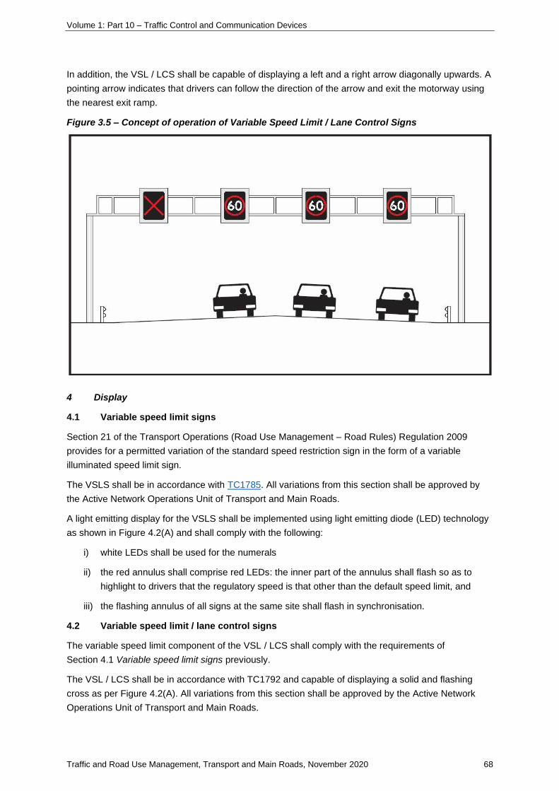
Volume 1: Part 10 – Traffic Control and Communication Devices
Traffic and Road Use Management, Transport and Main Roads, November 2020 68
In addition, the VSL / LCS shall be capable of displaying a left and a right arrow diagonally upwards. A
pointing arrow indicates that drivers can follow the direction of the arrow and exit the motorway using
the nearest exit ramp.
Figure 3.5 – Concept of operation of Variable Speed Limit / Lane Control Signs
4 Display
4.1 Variable speed limit signs
Section 21 of the Transport Operations (Road Use Management – Road Rules) Regulation 2009
provides for a permitted variation of the standard speed restriction sign in the form of a variable
illuminated speed limit sign.
The VSLS shall be in accordance with TC1785. All variations from this section shall be approved by
the Active Network Operations Unit of Transport and Main Roads.
A light emitting display for the VSLS shall be implemented using light emitting diode (LED) technology
as shown in Figure 4.2(A) and shall comply with the following:
i) white LEDs shall be used for the numerals
ii) the red annulus shall comprise red LEDs: the inner part of the annulus shall flash so as to
highlight to drivers that the regulatory speed is that other than the default speed limit, and
iii) the flashing annulus of all signs at the same site shall flash in synchronisation.
4.2 Variable speed limit / lane control signs
The variable speed limit component of the VSL / LCS shall comply with the requirements of
Section 4.1 Variable speed limit signs previously.
The VSL / LCS shall be in accordance with TC1792 and capable of displaying a solid and flashing
cross as per Figure 4.2(A). All variations from this section shall be approved by the Active Network
Operations Unit of Transport and Main Roads.

Volume 1: Part 10 – Traffic Control and Communication Devices
Traffic and Road Use Management, Transport and Main Roads, November 2020 69
It is required that the VSL / LCS also include the ability to display two white arrows as shown in
Figure 4.2(B). All variations from this section shall be approved by Active Network Operations of
Transport and Main Roads. The arrows shall comply with the following:
i) left arrows can only be displayed in the kerbside (left-most) lane(s), immediately upstream of a
left-hand side (LHS) exit ramp and right arrows can only be displayed in the
median (right-most) lane(s), immediately upstream of a right-hand side (RHS) exit ramp
ii) arrows shall not be displayed in lanes that do not have provision for traffic to exit
iii) arrows shall not be displayed in lanes other than those closest to the exit ramp, and
iv) arrows cannot be used to instruct traffic to merge into another mainline lane. Arrows can only
be used to direct traffic to exit the motorway.
Figure 4.2(A) – Variable speed limit and lane control signs
Variable speed limit Lane control sign
Figure 4.2(B) – Sign displays
Sign display for an open left-hand side exit during kerbside lane closure
Sign display for open right-hand side exit during median lane closure
Volume 1: Part 10 – Traffic Control and Communication Devices
Traffic and Road Use Management, Transport and Main Roads, November 2020 70
5 Sign placement
5.1 Exit points from a variable speed limit zone
Static speed restriction signs shall be provided at all exit points from a variable speed limit
zone (including on the mainline carriageways and at each exit ramp).
Static speed restriction signs shall be installed in accordance with Part 4 of the MUTCD.
Fixed speed zone on the mainline carriageway shall be established prior to an entry ramp. Placement
of a speed restriction sign R4-1 should allow suitable acceleration distance for the mainline traffic prior
to interacting with entering traffic.
Exit points on the mainline road shall be a distance downstream from the last VSLS consistent with
the maximum VSLS length (described as spacing in Section 6.3 Variable speed limit signs and
variable speed limit / lane control signs on motorway and long bridge carriageways).
5.2 Exit point from a variable speed limit and lane control zone
Further to Section 6.1 Exit points from a variable speed limit zone, mainline exit points from a lane
control zone shall be designated by a static Lane Control Ends sign (TC9060 as shown in Figure 6.2).
TC9060 shall be installed downstream from the last VSL / LCS on the mainline carriageway and
should be installed at a distance consistent with the average spacing guidelines (Section 6.3 Variable
speed limit signs and variable speed limit / lane control signs on motorway and long bridge
carriageways) of VSL / LCS on that mainline carriageway.
TC9060 should be installed prior to the exit ramp, immediately downstream of the last VSL / LCS to
allow sufficient safe merge distance of traffic from the furthermost lane to the exit and where a
minimum VSL / LCS length (described as spacing in Section 6.3 VSLS and VSL / LCS on motorway
and long bridge carriageways) between TC9060 and the last VSL / LCS cannot be achieved, it is
permitted to place TC9060 after the exit ramp. Installing a TC9060 downstream from an exit will
restrict the VSLS' and/or LCS’s ability to reopen lane(s) to allow drivers to exit.
Static speed restriction signs R4-1 shall be provided after the lane control ends sign and their
placement shall be in accordance with Section 6.1 Exit points from a variable speed limit zone.
Longitudinal placement of all signs shall be in accordance with Part 1 of the Queensland MUTCD and
the TC signs database.

Volume 1: Part 10 – Traffic Control and Communication Devices
Traffic and Road Use Management, Transport and Main Roads, November 2020 71
Figure 6.2 – TC9060 LANE CONTROL ENDS sign
5.3 Variable speed limit signs and variable speed limit / lane control signs on motorway
and long bridge carriageways
VSLS or VSL / LCS shall be placed after the entry points to the variable speed limit zone to reinforce
the current posted speed limit. The spacing between mainline variable speed limit signs (VSLS or
VSL / LCS) shall be between 400 and 600 meters. The average spacing shall be 500 metres, the
maximum spacing for VSLS shall not exceed 1000 meters.
A VSLS or VSL / LCS is required downstream of a motorway entrance ramp to reinforce the variable
speed limit to drivers as they enter a VSL zone. Entering a motorway provides a high workload for
drivers in terms of accelerating to the posted speed limit, merging with mainline traffic and observing
the road conditions ahead; therefore, it is necessary to provide this reinforcement after any
acceleration and merging has been completed and the driver is comfortable within the motorway
environment. To reinforce the speed limit, a VSLS or VSL / LCS shall be provided 200 to 400 metres
beyond the end of a motorway entry ramp taper (for both taper and parallel merges). For some parallel
merges, this distance may vary according to the site conditions; however, if the design does not
comply with this section, advice shall be sought from Traffic Engineering Technology and Systems,
Engineering & Technology, Transport and Main Roads. Where an added lane results at an entrance
ramp, the VSLS or VSL / LCS is to be located 200 to 400 metres downstream of the painted gore
area.
It is not permitted to place VSLS or VSL / LCS in a merge or diverge taper. Advice may be sought
from Active Network Operations, Engineering & Technology, Transport and Main Roads to place
VSLS or VSL / LCS in an added parallel lane.
It is not permitted to place a single repeater VSLS in a road environment with VSL / LCS. Advice for
inclusion of single repeater VSLS may be sought from Active Network Operations, Engineering &
Technology, Transport and Main Roads.
Default speed limit static signs are not required on repeater VSLS or VSL / LCS.
5.4 Repeater variable speed limit / lane control signs in tunnels
Repeater VSL / LCS shall be placed after the entry points to the tunnel to reinforce the current posted
speed limit.

Volume 1: Part 10 – Traffic Control and Communication Devices
Traffic and Road Use Management, Transport and Main Roads, November 2020 72
The spacing adopted is site-specific, such that motorists are able to view at least one downstream
sign at all times; therefore, the adopted spacing will depend on the sight distance to signs. The
maximum spacing shall be 240 metres.
For side-mounted VSLS (for tunnels where the lane control function is not required), the maximum
spacing shall be same as surface road as per MUTCD Part 4 requirements.
Default speed limit static signs shall not be provided on repeater VSL / LCS.
5.5 Change of maximum posted speed of road
Changes in the road geometry or road function may require a change to the maximum posted speed
limit in variable speed limit zones. In these circumstances, a new default speed limit sign (TC1568)
shall be installed in conjunction with the VSLS or VSL / LCS immediately upstream from the change.
5.6 Colocation of other signage with variable speed limit / lane control signs
On motorways or long bridges, it may be attractive to designers to collocate other signage (such as
static signage and variable message signs) on the same gantries as VSL / LCS. Designers shall be
aware of the amount of information presented to drivers at a single location. As such, the Road
Operations Directorate of Transport and Main Roads may require the designer to undertake driver
behaviour and comprehension studies prior to a decision being made about collocation.
Generally, in order to achieve optimal operational outcomes, lane-based static direction
signs (provided 500 m prior to major decision points) should be collocated with VSL / LCS. Advice
shall be sought from the Engineering and Technology Branch of Transport and Main Roads where this
is not possible.
Non-lane-based static direction signs (provided at a nominal distance of 1000 m prior to major
decision points) may be collocated with VSL / LCS in accordance with the requirements of the
Austroads Guide to Traffic Management and Section 5.7-2 in this supplement.
Variable message signs may be collocated with VSL / LCS in accordance with the requirements of the
Austroads Guide to Traffic Management and Section 5.7-2.
It is not permitted to collocate any signage other than that described previously (either static or
variable) with VSL / LCS.
5.7 System interchanges
At system interchanges, where two connecting motorways are controlled by variable speed limits, the
number of VSLS to be provided on the interchange ramps shall be the same as the requirement for
static signage (refer to MUTCD Part 4). Where the EXIT SPEED sign (W1-9-1) is required, it shall be
replaced with VSLS.
6 Maximum and minimum speed displays
VSLS and VSL / LCS shall be capable of displaying speeds in increments of 10 km/h between a
minimum of 20 km/h and a maximum of 110 km/h. These speeds are in accordance with the range
permitted in MUTCD Part 4 Speed Controls but are not absolute. During planning and design for
VSLS and VSL / LCS on a specific road, MUTCD requirements and operational strategies shall be
considered.

Volume 1: Part 10 – Traffic Control and Communication Devices
Traffic and Road Use Management, Transport and Main Roads, November 2020 73
7 Mounting arrangements
On motorways and long bridges, Table 8 shall be used to determine appropriate mounting
arrangements for VSLS and VSL / LCS. The details for side and overhead structure mountings are
contained in sections 8.1 Side-mounted and 8.2 Overhead structure mounting of this supplement.
For major diverge of parallel carriageway, refer to Transport and Main Roads’ ITS Placement
Guideline.
For mounting arrangements in tunnels, refer to Section 8.3 Tunnels of this supplement.
Table 8 – Mounting arrangements
Number of lanes (entry ramp
or carriageway) VSLS or VSL/LC
Mounting arrangement
required
1 VSLS Side-mounted
2–5 VSLS Side-mounted
VSL/LC Overhead structure
6 or more VSL/LC Overhead structure
7.1 Side-mounted
On single-lane entry ramps, a single VSLS shall be located on the left side of the ramp. On entry
ramps with two or more lanes, a VSLS shall be located on each side of the ramp, opposite
one another. While they are usually located in pairs, the signs may be separated longitudinally by up
to 200 m.
On motorways and long bridges with two or more lane carriageways where lane control is not
required, VSLS shall be located on each side of the carriageway, opposite one another. While they are
usually located in pairs, the signs may be separated longitudinally by up to 200 m.
On motorways, the VSLS shall be mounted on poles and set into the ground or mounted in concrete
barriers. Poles may only be installed in concrete barriers if the clearances comply with the working
widths as specified in the Austroads Guide to Road Design.
On long bridges, the VSLS shall be mounted on the bridge structure such that errant vehicles sliding
along the barrier cannot come into contact with the sign.
On entry ramps with variable speed limits and ramp metering, the VSLS shall be located downstream
of the ramp metering stop line. Spacing between signs shall comply with the MUTCD.
The VSLS using pole mounting arrangements shall be in accordance with Figure 8.1. The VSLS
pole-mounted installation shall include the installation of a safety barrier if the sign supports are
located within the clear zone (refer to Road Planning and Design Manual).
As a minimum, size C VSLS (TC1785) signs shall be installed.

Volume 1: Part 10 – Traffic Control and Communication Devices
Traffic and Road Use Management, Transport and Main Roads, November 2020 74
Figure 8.1 – Concept drawing for pole-mounted variable speed limit sign with supplementary
static default sign (where applicable)
7.2 Overhead structure mounting
On motorways and long bridges, overhead structure mounting is required when lane control is
required. The VSL / LCS shall be located on an overhead structure, with one sign located over the
centre of each lane, in accordance with Figure 3.5.

Volume 1: Part 10 – Traffic Control and Communication Devices
Traffic and Road Use Management, Transport and Main Roads, November 2020 75
The overhead structure may be either an overpass structure or a gantry. As a minimum,
size C VSL / LCS (TC1792), size as defined in Part 4 of the MUTCD, shall be installed. The VSL / LCS
overhead structure shall include:
i) minimum vertical clearance for heavy and oversize vehicles
ii) a safety barrier if the overhead structure supports are located within the clear zone
iii) in liaison with enforcement authorities, provision to mount and operate speed enforcement
devices, and
iv) protection from vandalism and unwanted public access to equipment especially where signs
are mounted on bridges with pedestrian access.
Lightweight gantries may be used as an overhead structure on bridges and where it is impracticable to
provide shoulders or parking facilities for maintenance personnel. The decision to adopt a light or
heavyweight gantry is a business decision at design stage.
7.3 Tunnels
In tunnels, entry ramp signs may be located overhead and may be integrated with lane control signs
where required to sign a tunnel closure.
The VSL / LCS shall be mounted centrally above each lane as shown in Figure 3.5 except signs are
roof-mounted instead of gantry-mounted.
Where tunnel height is insufficient to install VSL / LCS overhead, advice shall be sought from the
Road Operations Directorate of Transport and Main Roads.
Note: it may be possible to protrude part of the sign above the signage allocation into the duct, ventilation or
luminary space.
As a minimum, size B VSL / LCS (TC1792_1) shall be installed in tunnels. This sign may be used as a
repeater sign or to change the speed limit. Where specific constraints prevent the tunnel
accommodating this size sign, the designer and Principal may consider a smaller size display. Prior to
fabrication, the specifics of this smaller display shall be submitted to the Transport and Main Roads
Representative for consideration and advice from the Road Operations Directorate of Transport and
Main Roads.
8 Enforcement of variable speed limits
Enforcement of variable speed limits is essential to ensure compliance of the system. Enforcement
requirements, including site-specific warrants, methods of enforcement and the impact on various
aspects of the motorway design, shall be addressed on a project-by-project basis and in conjunction
with the Customer, Traffic Engineering Technology and Systems, Engineering & Technology,
Transport and Main Roads and Land Transport Safety Directorate of Transport and Main Roads, and
QPS.
9 Associated Intelligent Transport System devices
It is recommended that closed circuit television (CCTV) is provided such that all VSLS or
VSL / LCS displays are visible to Traffic Management Centre (TMC) operators both night and day.
Mainline vehicle detector sites should be located with each VSLS and VSL / LCS, in accordance with
Transport and Main Roads TRUM Volume 4 ITS and Electrical Technology Part 2 Road Lighting
Maintenance.

Volume 1: Part 10 – Traffic Control and Communication Devices
Traffic and Road Use Management, Transport and Main Roads, November 2020 76
Weather monitoring stations may also be considered as an input for STREAMS under either manual
or automatic control.
VSLS and VSL / LCS relating to tunnels should consider TRUM Volume 1 Part 9 for information in
relation to traffic management practices for tunnel closures.
10 Considerations of future upgrade projects
If future upgrade projects are planned for a section of road where VSLS or VSL / LCS is being
designed, road designers need to take into consideration the future road geometry when determining
the location and mounting arrangements for VSLS and VSL / LCS.
11 Selection of a gantry type for lane use management system, variable speed limit signs
and other signs
Selection of the appropriate gantry type is based on functional requirements. In general, gantries
extend from one side of the carriageway or road to the other side (of the carriageway or road). There
are other ways of supporting signs; for example, side mounted on posts, on an overpass structure,
lightweight gantry structure.
This section refers to the traditional gantries, although there needs to be continued innovation to
design and use systems that reduce the cost of construction, maintenance of the gantry and the
devices and signs installed on the gantry.
In selecting a gantry type, designers need to consider its function.
1. Are cameras and other devices going to be used for enforcement?
Enforcement devices require gantries to be stiffer and to limit both deflection and vibration.
Cameras for automated number plate recognition (ANPR) systems that are used for tracking
vehicle movements may not need the same restriction of gantry deflection if not used for
enforcement.
2. What are the types of signs that will be supported by the gantry?
The number and type of signs will affect the strength of the gantry; for instance, whether there
will be VSL / LC, or VSLS signs alone, whether there will be static signs or changeable
message signs installed as well.
3. Is there a need for power and communication links to be taken across the road or
carriageway?
This may require a gantry when other mountings may have been satisfactory.
4. Can the maintenance of the gantry and devices it carries be maintained using a cherry picker
or must the gantry be a ‘walk-on’ type?
Other gantry types in the vicinity may also influence this decision. If there are a number of
other gantries that are maintained from below, and if several gantries can have their
maintenance at the one time, then this may affect the decision. The whole-of-life costs of the
system need to be identified.
5. Can the gantry be secure from trespassers?
This decision may not affect the type of gantry, but it does affect its configuration.
The following flow chart lists the important decisions in selecting a gantry type.

Volume 1: Part 10 – Traffic Control and Communication Devices
Traffic and Road Use Management, Transport and Main Roads, November 2020 77
Figure 12 – Selection of a gantry type

Volume 1: Part 10 – Traffic Control and Communication Devices
Traffic and Road Use Management, Transport and Main Roads, November 2020 78
5.7-2 Collocation of gantry-mounted variable speed limit signs with static and
monochrome variable message signs
1 Introduction
This supplement provides guidance when collocating static and dynamic signs on the same supporting
gantry as variable speed limit (VSL) signs.
The ever-increasing traffic volumes occurring on highways is not only resulting in an increase in the
number of traffic lanes required to cope with this traffic, but also changes in the way traffic is managed
on highways in general. In addition to providing operational benefits, the introduction of new
technology such as lane-based VSL and other Intelligent Transport System (ITS) devices provides
potential for the collocation of ITS devices with other signs on overhead gantries.
Collocation maximises the use of overhead gantries and reduces the need for side-mounted signs. In
addition, due to the number of static and dynamic message devices being placed on the road network,
lateral spacing requirements between signage may not be met and collocation is a viable alternative.
2 Scopes
This supplement provides information for the design and construction of motorway direction signs,
gantry-mounted VSL signs and dynamic signs in Queensland.
This supplement adds to existing motorway signing provisions in Part 15 of the Queensland
MUTCD / AS1742.15 Direction signs, information signs and route numbering for gantry-mounted
advance direction signs as a replacement for roadside-mounted signs.
3 Collocation of gantry-mounted variable speed limit signs and advance direction signs
The collocation of static advance direction signs (SADS) with VSL signing should be applied whenever
there is the opportunity to make full use of existing or proposed gantries and/or in the following
circumstances:
a) where the exit is located partway around a left curve or just beyond a crest, or
b) when roadside features, such as batters, make installation of roadside signs impracticable.
This application relates to highway junctions with a single exit, identified by the number and distance
shown in the exit plate, which is located to the lower left side of the direction signs. The exit
destinations and routes are shown in the upper left side of the direction sign and with an indication of
the destinations reached by remaining on the motorway. For a single exit off a highway, the exit
should be signed 1 km in advance of the exit as shown in Figure 3.1(A).
The decision to collocate SADS and VSLS should ensure consistency of application along a given
route.

Volume 1: Part 10 – Traffic Control and Communication Devices
Traffic and Road Use Management, Transport and Main Roads, November 2020 79
3.1 Typical layout
Figure 3.1(A) – Collocation of gantry-mounted SADS and VSLS in the case of a single exit
When collocation of gantry-mounted SADS and VSL occurs, it will not be necessary to provide
additional side-mounted roadside signage such as GE1-12-1 (shown in Figure 3.1(B)).
Figure 3.1(B) – GE1-12-1 signage

Volume 1: Part 10 – Traffic Control and Communication Devices
Traffic and Road Use Management, Transport and Main Roads, November 2020 80
3.2 Benefits of gantry-mounted variable speed limit and advance direction signs
The collocation of gantry-mounted SADS and VSLS provides a number of operational and safety
benefits:
a) allows flexibility for individual lane-based direction signs
b) increased visibility of direction signs in all lanes
c) removes the potential for direction signs to be obstructed by commercial traffic
d) creates potential for cost-neutral outcomes or, in some instances, reduced costs from using
existing / proposed gantries rather than the provision of additional support structures for
side-mounted roadside signage.
4 Collocation of gantry-mounted variable speed limit and monochrome variable message
signs
The decision to collocate VSL and VMS should only be considered for monochrome signs in severely
constrained environments and is acceptable, subject to:
a) approval of significant corridor constraints by relevant regions
b) compliance with relevant standards and guidelines.
4.1 Typical layout
Figure 4.1 – Collocation of monochrome variable message signs and variable speed limit signs

Volume 1: Part 10 – Traffic Control and Communication Devices
Traffic and Road Use Management, Transport and Main Roads, November 2020 81
4.2 Benefits of gantry-mounted variable speed limit and monochrome variable message
signs
The collocation of gantry-mounted VSL and a monochrome VMS has the potential to provide a
number of benefits:
• aid compliance by reinforcing speed reduction and/or lane closures in place for traffic
management
• increased visibility of VMS in all lanes
• removes the potential for VMS to be obstructed by commercial traffic
• creates potential for cost-neutral outcomes or, in some instances, reduced costs from using
existing / proposed gantries rather than the provision of additional support structures for
side-mounted roadside signage.
Volume 1: Part 10 – Traffic Control and Communication Devices
Traffic and Road Use Management, Transport and Main Roads, November 2020 82
5.8 Portable / temporary variable message signs
5.8-1 Use of temporary variable speed limit signs in construction and maintenance
work areas on motorways
This content has been incorporated into the Queensland Guide to Temporary Traffic
Management (QGTTM) released on 30 November 2020.

Volume 1: Part 10 – Traffic Control and Communication Devices
Traffic and Road Use Management, Transport and Main Roads, November 2020 83
6 Pavement markings
6.3 Line marking materials
6.3.3 Barrier lines
6.3.3-1 Determination of centre line markings adjacent to property access
1 Introduction
The purpose of this supplement is to provide information that assists in determining the appropriate
centre line marking (a single continuous, unidirectional continuous dividing line or a double barrier line)
to allow motorists from turning right either into or out of a property access, or to restrict such
movement.
Note: Rule 134 of the Transport Operations (Road Use Management – Road Rules) Regulation 2009 permits a
driver to cross a continuous dividing line to enter or leave the road, but not to overtake (a continuous dividing line
includes both a single continuous dividing line and a continuous dividing line to the left of a broken dividing line).
2 Assessment criteria
Determination of the line marking at the centreline adjacent to a property access is highly susceptible
to having adequate sight distance. Adequate sight distance is referred as the capacity for the
stationary vehicle to select a gap in oncoming traffic to make the right turn, and also to have sight
distance for the vehicles in behind to either stop when they have identified the presence of the
stationary vehicle or decelerate and pass to the left of the stationary vehicle.
Adequate sight distance is determined sufficient when standard requirements for Sight distance at
property entrances and Stopping sight distance provided in the Austroads Guide to Road
Design (AGRD) are satisfied.
Requirements to sight distance at property entrances are provided in Section 3.2.3, Part 4A AGRD.
Requirements of stopping sight distance are provided in Section 5.3, Part 3 AGRD.
3 Line marking
A single continuous or unidirectional continuous dividing line may be installed when sufficient sight
distance is present and is determined as adequate sight distance to allow right turning manoeuvres
either into or out of the property access. Where adequate sight distance is not met, a double barrier
line may be used to restrict such movement.
Modification to the existing line marking is required when potential safety problems are identified using
the methodology (Assessment criteria) outlined in this supplement. The minimum length of double
barrier line that should be marked is 40 m (that is, 20 m each side of the property access).
Consideration should also be given to impacts on other property accesses, which meet the
assessment criteria and the presence of double barrier line marking in the near vicinity (it may be
necessary to join new barrier lines with existing lines).
Volume 1: Part 10 – Traffic Control and Communication Devices
Traffic and Road Use Management, Transport and Main Roads, November 2020 84
4 Consultation
The property owner should be consulted, given that modification of property access line marking from
unidirectional to double barrier lines will always result in the restriction of one existing legal
movement (for example, marking a double barrier line to restrict right turns into a property access from
a road retains the status quo of the right-turn movement into the property, but makes the existing legal
right-turn movement from the property illegal).

Volume 1: Part 10 – Traffic Control and Communication Devices
Traffic and Road Use Management, Transport and Main Roads, November 2020 85
6.5 Other markings
6.5-1 Bicycle Awareness Zones
1 Purpose
This supplement provides guidelines for the provision of Bicycle Awareness Zones (BAZ) as an
advisory treatment. Traffic engineering judgement needs to be applied to site-specific treatments to
ensure that BAZ treatments are used safely, taking into account local conditions.
BAZ treatments are ‘retrofit only’ facilities for application to the existing road surface. BAZ must not be
used in greenfield or capital improvement projects.
1.1 Introduction
Advisory treatments are defined as:
…treatments are used to indicate or advise road users of the potential presence of cyclists
and of the location where cyclists may be expected to ride on a road (AS1742.9: 2018).
Within Queensland, there are currently different approaches to implementing advisory treatments for
cyclists. This section has been developed to assist with broader application of the BAZ treatment in
Queensland and to ensure that the treatment receives consistent applications across both state and
local governments.
1.2 Transport and Main Roads policy
BAZ treatments are not considered ‘explicit provision’ under the Transport and Main Roads Cycling
Infrastructure Policy. BAZ treatments are considered ‘implicit provision’ if used in accordance with the
instructions provided in this section. At all times, Transport and Main Roads will strongly pursue the
implementation of safer bicycle facilities in lieu of BAZ.
The BAZ treatment attempts to promote safer road user behaviours; its ability to improve road safety
is weak compared to dedicated facilities that separate motor vehicles and bicycles. BAZ treatments
shall only be used as a treatment of last resort where the existing road surface cannot be manipulated
to support visual of physical separation of motor vehicles and bicycles. BAZ must not be used as a
mid-block treatment in greenfield or capital improvement projects.
1.3 Related documents
This supplement should be read in conjunction with the following guidelines:
• Queensland Department of Transport and Main Roads:
− Queensland Manual of Uniform Traffic Control Devices
▪ Part 9: Bicycle Facilities, and
▪ Part 11: Parking Controls.
− Road Planning and Design Manual
− Traffic and Road Use Management manual Volume 1: Guide to Traffic Management,
Part 8: Local area traffic management, and
• Australian Standard AS 2890.5 Parking facilities, Part 5: On-street parking.

Volume 1: Part 10 – Traffic Control and Communication Devices
Traffic and Road Use Management, Transport and Main Roads, November 2020 86
2 Bicycle Awareness Zones: description and use
BAZ are advisory treatments, similar to warning signs. BAZ are used to indicate or ‘advise’ road users
of the potential presence of cyclists and the position where cyclists may be expected to ride on the
road. A BAZ treatment gives a similar message to, and may be used in conjunction with, a
W6-7 (Bicycle warning) sign as specified in MUTCD Part 9.
BAZ are not dedicated bicycle facilities –they do not serve a route provision function. They serve only
as a warning function. Dedicated on-road bicycle facilities are represented by white-painted bicycle
symbols, pole-mounted signs and unbroken lane lines as per MUTCD Part 9.
The BAZ symbol is used to alert motorists that cyclists must temporarily leave the far left of the road
space to ensure their own safety. The use of the BAZ symbol does not override the road rule (S129)
requiring drivers (including riders of bicycles) to keep as near as practicable to the far left side of the
road; rather, the BAZ symbol is to be used in situations that have been identified by a road authority
as being ones where it is not possible to ride safely on the far left side of the road.
2.1 Pavement marking specification
A BAZ is marked by on-road yellow bicycle symbols. The bicycle symbol shall comply with
Figure 2.2(1) in MUTCD Part 9, with a preferred dimension of 1100 mm x 1800 mm. For extra
emphasis over short lengths (for example, 100 m or less) of highly constrained road (for example, over
a narrow bridge), 1530 mm x 2500 mm symbols may be used. Symbols are to be coloured
yellow (Y14 Golden Yellow colouring as defined in AS 2700) and placed at nominal intervals of 200 m
or less. Additional symbols may be required on curves and crests to ensure the symbols remain visible
to drivers. The markings and their application to streets and roads are described fully in
Section 3 Design and implementation of Bicycle Awareness Zones of this supplement.
Figure 2.1 – Bicycle Awareness Zone for insufficient lane width
This example of the preferred pavement marking layout for BAZ shows it applied to a narrowing at a two-lane
bridge (Bli Bridge Eastern approach (SKM 2011)). BAZ is primarily a mid-block treatment, although the treatment
may be used on the approach and departure of intersections and roundabouts.

Volume 1: Part 10 – Traffic Control and Communication Devices
Traffic and Road Use Management, Transport and Main Roads, November 2020 87
2.2 The intended purpose of Bicycle Awareness Zones
BAZ are used on sections of roadway to:
• increase awareness among motorists and cyclists of the need to share road space to
maximise safety for cyclists
• warn both cyclists and motorists that the road is not wide enough to accommodate a standard
bicycle lane and that they should consequently be more cautious
• show the likely path of travel and positioning of cyclists on the road
• encourage cyclists to position themselves where they have maximum visibility to motorists
• reinforce that bicycles may use the entire lane, where there is insufficient lane width for a
motor vehicle to safely pass (Figure 2.1)
• improve driver tolerance of cyclists at pinch points4
• influence vehicle positioning within the lane (Figure 2.2) and increase passing clearance, and
• encourage considerate driving behaviour, such as motorists only attempting to pass cyclists
where there is adequate lane width.
Figure 2.2 – Bicycle Awareness Zone to influence vehicle positioning
This photo shows the application of BAZ symbols on a narrow street to influence the positioning of cyclists and
motorists in situations where dedicated bicycle lanes may not be possible (Grey St, South Bank).
4 Research finding from: (SKM 2011) Evaluation of narrow bridge treatments for cyclists’ safety. Prepared for Transport and Main Roads.
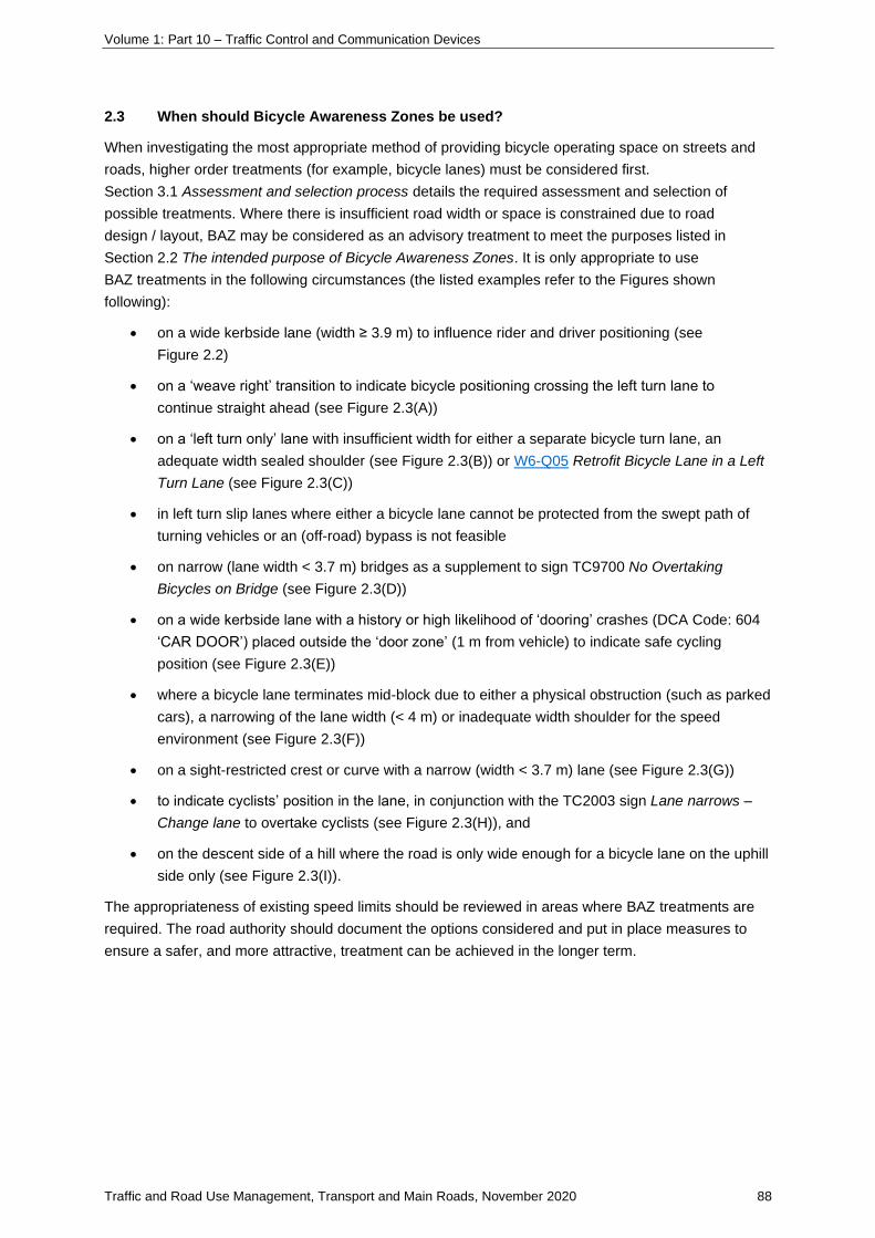
Volume 1: Part 10 – Traffic Control and Communication Devices
Traffic and Road Use Management, Transport and Main Roads, November 2020 88
2.3 When should Bicycle Awareness Zones be used?
When investigating the most appropriate method of providing bicycle operating space on streets and
roads, higher order treatments (for example, bicycle lanes) must be considered first.
Section 3.1 Assessment and selection process details the required assessment and selection of
possible treatments. Where there is insufficient road width or space is constrained due to road
design / layout, BAZ may be considered as an advisory treatment to meet the purposes listed in
Section 2.2 The intended purpose of Bicycle Awareness Zones. It is only appropriate to use
BAZ treatments in the following circumstances (the listed examples refer to the Figures shown
following):
• on a wide kerbside lane (width ≥ 3.9 m) to influence rider and driver positioning (see
Figure 2.2)
• on a ‘weave right’ transition to indicate bicycle positioning crossing the left turn lane to
continue straight ahead (see Figure 2.3(A))
• on a ‘left turn only’ lane with insufficient width for either a separate bicycle turn lane, an
adequate width sealed shoulder (see Figure 2.3(B)) or W6-Q05 Retrofit Bicycle Lane in a Left
Turn Lane (see Figure 2.3(C))
• in left turn slip lanes where either a bicycle lane cannot be protected from the swept path of
turning vehicles or an (off-road) bypass is not feasible
• on narrow (lane width < 3.7 m) bridges as a supplement to sign TC9700 No Overtaking
Bicycles on Bridge (see Figure 2.3(D))
• on a wide kerbside lane with a history or high likelihood of ‘dooring’ crashes (DCA Code: 604
‘CAR DOOR’) placed outside the ‘door zone’ (1 m from vehicle) to indicate safe cycling
position (see Figure 2.3(E))
• where a bicycle lane terminates mid-block due to either a physical obstruction (such as parked
cars), a narrowing of the lane width (< 4 m) or inadequate width shoulder for the speed
environment (see Figure 2.3(F))
• on a sight-restricted crest or curve with a narrow (width < 3.7 m) lane (see Figure 2.3(G))
• to indicate cyclists’ position in the lane, in conjunction with the TC2003 sign Lane narrows –
Change lane to overtake cyclists (see Figure 2.3(H)), and
• on the descent side of a hill where the road is only wide enough for a bicycle lane on the uphill
side only (see Figure 2.3(I)).
The appropriateness of existing speed limits should be reviewed in areas where BAZ treatments are
required. The road authority should document the options considered and put in place measures to
ensure a safer, and more attractive, treatment can be achieved in the longer term.

Volume 1: Part 10 – Traffic Control and Communication Devices
Traffic and Road Use Management, Transport and Main Roads, November 2020 89
Figure 2.3(A) – Weave right transition
Weave right transition marked with a BAZ symbol to clearly indicate cyclists’ positioning when transitioning to
continue through the intersection (Gympie Road, Stafford).
Figure 2.3(B) – Left turn lane
The left turn lane is marked with a BAZ symbol to clearly indicate cyclists’ positioning and turning intention when
turning left. Cyclists are advised to travel in the middle of the lane for their own safety (Gympie Road, Stafford).
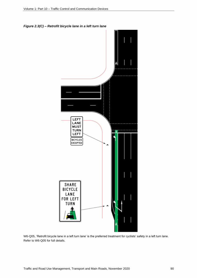
Volume 1: Part 10 – Traffic Control and Communication Devices
Traffic and Road Use Management, Transport and Main Roads, November 2020 90
Figure 2.3(C) – Retrofit bicycle lane in a left turn lane
W6-Q05, ‘Retrofit bicycle lane in a left turn lane’ is the preferred treatment for cyclists’ safety in a left turn lane.
Refer to W6-Q05 for full details.

Volume 1: Part 10 – Traffic Control and Communication Devices
Traffic and Road Use Management, Transport and Main Roads, November 2020 91
Figure 2.3(D) – Narrow bridge
This narrow bridge in Noosa has no bicycle lane or adequate-width shoulder. BAZ symbols have been applied to
the travel lanes. The positioning of the BAZ symbols indicates to cyclists that they travel in the centre of the travel
lane for their own safety. The sign erected on the bridge approach is a specific LGA response to the issue. The
sign TC9700 No overtaking bicycles on bridge (see inset) is recommended for erection on both bridge
approaches.
Figure 2.3(E) – Wide kerbside lane
BAZ symbols used in a wide kerbside lane with a history or high likelihood of ‘dooring’ crashes. The pavement
symbols are placed outside the ‘door zone’ (1 m from vehicle) to indicate a safe cycling position. See Figure 4 and
Figure 4.1.1(A), Figure 4.1.1(B) and Figure 4.1.1(C) for detailed guidance on the placement of BAZ symbols.

Volume 1: Part 10 – Traffic Control and Communication Devices
Traffic and Road Use Management, Transport and Main Roads, November 2020 92
Figure 2.3(F) – Bicycle lane terminates mid-block
BAZ symbols are used to clearly indicate cyclists positioning when a bicycle lane terminates mid-block due to a
narrowing of the lane or an obstruction, for example, parked cars. The right pair of diagrams shows the layout for
a clearway with parking out of peak. Where the lane narrows, cyclists are advised to travel in the middle of the
lane for their own safety to keep clear of the ‘door zone’.
Note: The drawings in this figure are indicative only. For greater detail, refer to TC1962 and Figure 4 and
Figure 4.1.1(A), 4.1.1(B) and Figure 4.1.1(C) for dimensioning.
Figure 2.3(G) – Narrow road lanes on sight-restricted corners
Narrow road lanes on a sight-restricted corners where BAZ symbols clearly indicate cyclists’ positioning. Cyclists
are advised to travel in the middle of the lane for their own safety (St Lucia, Brisbane and Noosa).

Volume 1: Part 10 – Traffic Control and Communication Devices
Traffic and Road Use Management, Transport and Main Roads, November 2020 93
Figure 2.3(H) – TC2003 sign assembly for road or lane narrowing
The TC2003 sign assembly recommended for use in conjunction with a BAZ treatment where road or lane
narrowing occurs.
Figure 2.3(I) – Bicycle Awareness Zone on descending hill
The use of BAZ would be appropriate in this situation on the descending side of a hill where the road is only wide
enough for one bicycle lane on the uphill side. The median is required to accommodate a right-turn lane and
parking prohibitions are in place on the descending lane. Refer also to MUTCD Part 9 Bicycle facilities
section 2.4.1 and MUTCD Part 2 Figure 4.16(a) Zip Merge (Hamilton Rd, Brisbane).

Volume 1: Part 10 – Traffic Control and Communication Devices
Traffic and Road Use Management, Transport and Main Roads, November 2020 94
2.4 When are Bicycle Awareness Zones not suitable?
BAZ are not suitable treatments in the following situations:
• in greenfield applications – higher order bicycle facilities, such as bicycle lanes and paths,
should always be provided in newly developing areas
• on roads with posted speeds greater than 70 km/h
• where bicycle lanes are achievable through minimal infrastructure works (for example, lane
width reallocation after resurfacing program), and
• as a wayfinding device or ‘gap-filling’ in mixed off-road / on-road routes.
The BAZ treatment is used primarily as a warning symbol, similar to green pavement treatment. Its
use needs to be limited to conflict / danger points.
The images following illustrate outdated applications of the BAZ treatment although they met the
relevant guidelines at the time of installation. Research undertaken by Transport and Main Roads has
shown that motorists confuse this treatment with bicycle lanes, which pressures cyclists to ride in the
‘door zone’5. Rather, cyclists should be encouraged to ride away from the ‘dooring’ zone through the
use of painted buffers, shared lane markings and traffic calming that encourages lane sharing6. At the
same time, authorities must ensure the road space is most effectively used by marking parking bays
that are no wider than absolutely necessary in order to encourage parking discipline as close to the
kerb as possible7.
Figure 2.4(A) – Inappropriate use of Bicycle Awareness Zone on the inside of an edge line
BAZ symbol used inappropriately on the inside of an edge line, encouraging cyclists to travel in the ‘door zone’,
increasing the likelihood of a serious crash (Tahiti Ave, Palm Beach).
5 Smart, N. (2011) An Evaluation of Bicycle Awareness Zones. Report for Transport and Main Roads. 6 CDM Research (2012) Bicycle Rider Collisions with Car Doors Report commissioned for Road Safety Action Group Melbourne. 7 CDM Research (2012) Bicycle Rider Collisions with Car Doors Report commissioned for Road Safety Action Group Melbourne.
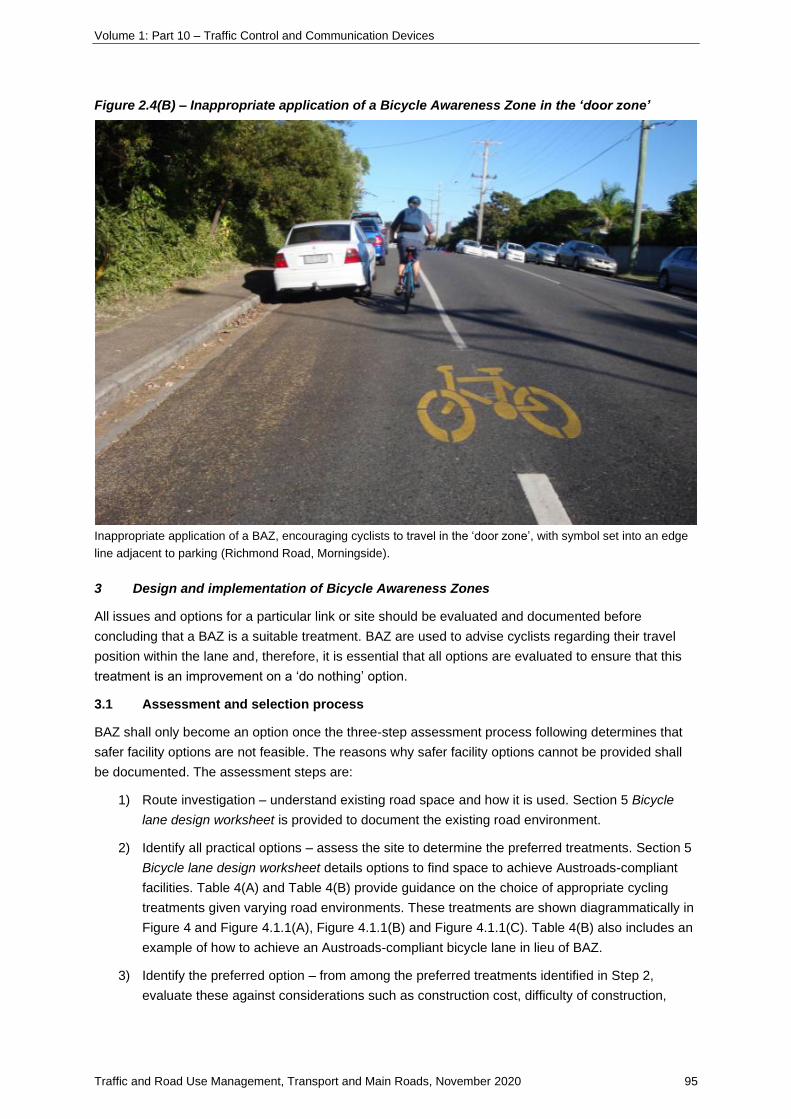
Volume 1: Part 10 – Traffic Control and Communication Devices
Traffic and Road Use Management, Transport and Main Roads, November 2020 95
Figure 2.4(B) – Inappropriate application of a Bicycle Awareness Zone in the ‘door zone’
Inappropriate application of a BAZ, encouraging cyclists to travel in the ‘door zone’, with symbol set into an edge
line adjacent to parking (Richmond Road, Morningside).
3 Design and implementation of Bicycle Awareness Zones
All issues and options for a particular link or site should be evaluated and documented before
concluding that a BAZ is a suitable treatment. BAZ are used to advise cyclists regarding their travel
position within the lane and, therefore, it is essential that all options are evaluated to ensure that this
treatment is an improvement on a ‘do nothing’ option.
3.1 Assessment and selection process
BAZ shall only become an option once the three-step assessment process following determines that
safer facility options are not feasible. The reasons why safer facility options cannot be provided shall
be documented. The assessment steps are:
1) Route investigation – understand existing road space and how it is used. Section 5 Bicycle
lane design worksheet is provided to document the existing road environment.
2) Identify all practical options – assess the site to determine the preferred treatments. Section 5
Bicycle lane design worksheet details options to find space to achieve Austroads-compliant
facilities. Table 4(A) and Table 4(B) provide guidance on the choice of appropriate cycling
treatments given varying road environments. These treatments are shown diagrammatically in
Figure 4 and Figure 4.1.1(A), Figure 4.1.1(B) and Figure 4.1.1(C). Table 4(B) also includes an
example of how to achieve an Austroads-compliant bicycle lane in lieu of BAZ.
3) Identify the preferred option – from among the preferred treatments identified in Step 2,
evaluate these against considerations such as construction cost, difficulty of construction,

Volume 1: Part 10 – Traffic Control and Communication Devices
Traffic and Road Use Management, Transport and Main Roads, November 2020 96
impact on other stakeholders, level of service and consistency along the route. Document the
preferred option using the Section 5 Bicycle lane design worksheet.
3.1.1 Documentation and approval
Section 5 Bicycle lane design worksheet must be completed for every BAZ treatment and signed off
by an RPEQ.
3.1.2 Design audit
The design audit is a risk assessment to be carried out pre-installation to identify any additional factors
or problems that might make the proposed location unsuitable for installation of a BAZ.
3.1.3 Post-installation audit
A post-installation audit should be undertaken by a qualified road safety auditor to identify any safety
issues in the operation of the BAZ. Austroads Guide to Road Design Part 6A (Appendix D) outlines an
example of a Bicycle Safety Audit checklist – this should be used as the basis for the whole-of-route
bicycle safety audit. Further information can be obtained from the Austroads Guide to Road Safety
Part 6: Road Safety Audit.
3.1.4 Education
In order to enhance road users’ understanding of the role of BAZ, a local education campaign targeted
at motorists and cyclists should be implemented following the infrastructure works.
4 Bicycle Awareness Zones lane configurations and pavement marking layouts
This section outlines the lane width requirements and pavement marking layouts required. All
dimensions shown are for a single lane of traffic. In some instances, it may be necessary to relocate
the centreline to accommodate both parking and safe advisory treatments for cyclists – for example,
providing parallel parking on only one side of the road.
Table 4(A) – Lane configurations without parking
Total lane width Vehicle lane width Cyclist facility Comments
2.8 m to 3.6 m 2.8 m (min) to 3.6 m
BAZ (without edge line)
See Figure 4
Not recommended on ascending (uphill) lane
3.7 m to 3.9 m 3.7 m to 3.9 m Wide kerbside lane
BAZ (with edge line)
See Figure 4.1.1(C)
4.0 m or greater 2.8 m vehicle lane width (min)
1.2 m bike lane achieved (min)

Volume 1: Part 10 – Traffic Control and Communication Devices
Traffic and Road Use Management, Transport and Main Roads, November 2020 97
Figure 4 – Dimensions for Bicycle Awareness Zones without edge lines and without parking
Table 4(B) – Lane configurations with parallel parking
Total lane width Vehicle lane width Shared cyclist/parking facility Comments
Less than 6 m Parking not recommended
6 m to 6.6 m 3.2 m to 3.6 m BAZ (without edge line)
(2.3 m (min) parking bays with 0.5 clearance required)8
Not recommended on ascending (uphill) lane
6.7 m to 6.9 m 3.7 m to 4.1 m BAZ (with edge line)
See Figure 4.1.1(C)
(2.3 m (min) parking bays with 0.5 clearance required)9
7 m or greater 4.2 m 1.2 m bike lane achieved (min)
Where on-street parking cannot be provided in compliance with AS 2890.5, it should be removed.
Provision of disabled parking bays is not recommended in a parallel parking configuration due to the
risk posed by passing traffic.
4.1.1 Important note on parking restrictions to reduce car turnover and increase cyclists’
safety
Although these width and line marking requirements encourage motorists to park as close to the kerb
face as possible, there is still a risk for cyclists riding in the ‘door zone’ because some motorists may
park well clear of the kerb. A vehicle parked on the kerbside only presents a car ‘dooring’ risk when an
occupant enters or leaves that vehicle10. As such, the nature of the parking provision must be
8 Refer to Australian Standard AS 2890.5, Section 2.4(a) and Table 2.1 9 Refer to Australian Standard AS 2890.5, Section 2.4(a) and Table 2.1 10 CDMR 2012. Bicycle Rider Collisions with Car Doors. Report prepared for the Road Safety Action Group. CDM Research. Melbourne, Victoria.

Volume 1: Part 10 – Traffic Control and Communication Devices
Traffic and Road Use Management, Transport and Main Roads, November 2020 98
assessed to determine the risk to cyclists’ safety. If the number of events (that is, the number of times
a door is opened) can be reduced, then the risk of conflict would also be reduced11. By reducing
vehicle turnover, the risk to cyclists of a ‘dooring’ crash will decrease proportionally.
Different types of parking zones will also have different rates of turnover; for example, loading zones
and taxi zones, by their very nature, will attract vehicles that are constantly opening their doors and
will have short parking times, resulting in a high rate of vehicles entering and exiting the parking
spaces.
In constrained lane-width environments, where there is a need to place an advisory treatment for
cyclists’ safety, it is recommended that parking allocations and time restrictions be reviewed also, with
a preference given to longer time period parking restrictions and residential or commuter parking.
It is acknowledged that this is a site-specific decision and will likely be affected by the destinations that
the parking serves; for example, a retail precinct with service outlets, such as supermarkets, milk bars
or newsagents, will probably generate far more parking turnover events than clothing stores12.
11 CDMR 2012. 12 CDMR 2012.

Volume 1: Part 10 – Traffic Control and Communication Devices
Traffic and Road Use Management, Transport and Main Roads, November 2020 99
Figure 4.1.1(A) – Dimensions for Bicycle Awareness Zones on a two-lane, general traffic road
with parallel parking
Notes for Figure 4.1.1(A)
1. AS 2890.5 requires 2.3 m width for parking space for cars and light commercial vehicles.
2. AS 2890.5 requires 0.5 m clearance from the nearest moving traffic lane, in a traffic speed
environment <60 km/h. Additional 1 m clearance required for every additional 10 km/h to a maximum of
3 m.
3. As per AS 2890, in Australia, 85 per cent of cars have width dimension less than 1860 mm.
4. As per the research report (CDMR 2012), it is required to ensure road space is most effectively used by
marking parking bays that are no wider than absolutely necessary in order to encourage parking
discipline as close to the kerb as possible.
5. The bicycle rider collision with car doors research report states that cycling within a distance of 1 m from
a kerbside parking space, places cyclists at risk should a car door open.
6. In instances of general traffic lane widths of <3.6 m, there is insufficient space for a car to safely pass a
bicycle. In these instances, the bicycle should occupy the middle of the lane to improve visibility to
motorists and to clearly communicate to motorists that it is unsafe to attempt to pass the cyclist while
remaining in the lane.
7. In instances of general traffic lane widths between 3.7–3.9 m, there is sufficient space for a car to safely
pass a bicycle.
8. In instances of general traffic lane widths >4 m, there is sufficient space for a bicycle lane.
9. Symbol should be paced between wheel paths, notionally 1.3 m subject to local conditions.

Volume 1: Part 10 – Traffic Control and Communication Devices
Traffic and Road Use Management, Transport and Main Roads, November 2020 100
Figure 4.1.1(B) – Dimensions for Bicycle Awareness Zones on a multi-lane, general traffic road
with parallel parking
Notes for Figure 4.1.1(B)
1. AS 2890.5 requires 2.3 m width for parking space for cars and light commercial vehicles.
2. AS 2890.5 requires 0.5 m clearance from the nearest moving traffic lane, in a traffic speed environment
< 60 km/h. Additional 1 m clearance required for every additional 10 km/h to a maximum of 3 m.
3. As per AS 2890, in Australia, 85 per cent of cars have width dimension less than 1860 mm.
4. As per the research report (CDMR 2012), it is required to: ensure road space is most effectively used by
marking parking bays that are no wider than absolutely necessary in order to encourage parking
discipline as close to the kerb as possible.
5. The bicycle rider collision with car doors research report states that cycling within a distance of 1 m from
a kerbside parking space, places cyclists at risk should a car door open.
6. This scenario assumes that the parking spaces are only unoccupied during the peak hours of a
single direction of flow of traffic (for example, 7am–9am inbound or 4pm–6pm outbound). The majority of
time the cyclists will be required to travel clear of the door zone for their own safety. During peak times,
cyclists are expected to comply with the road rule (S129) requiring road users to keep as the far-left side
of the road as practicable.
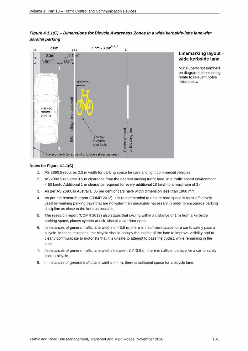
Volume 1: Part 10 – Traffic Control and Communication Devices
Traffic and Road Use Management, Transport and Main Roads, November 2020 101
Figure 4.1.1(C) – Dimensions for Bicycle Awareness Zones in a wide kerbside-lane lane with
parallel parking
Notes for Figure 4.1.1(C)
1. AS 2890.5 requires 2.3 m width for parking space for cars and light commercial vehicles.
2. AS 2890.5 requires 0.5 m clearance from the nearest moving traffic lane, in a traffic speed environment
< 60 km/h. Additional 1 m clearance required for every additional 10 km/h to a maximum of 3 m.
3. As per AS 2890, in Australia, 85 per cent of cars have width dimension less than 1860 mm.
4. As per the research report (CDMR 2012), it is recommended to ensure road space is most effectively
used by marking parking bays that are no wider than absolutely necessary in order to encourage parking
discipline as close to the kerb as possible.
5. The research report (CDMR 2012) also states that cycling within a distance of 1 m from a kerbside
parking space, places cyclists at risk, should a car door open.
6. In instances of general traffic lane widths of <3.6 m, there is insufficient space for a car to safely pass a
bicycle. In these instances, the bicycle should occupy the middle of the lane to improve visibility and to
clearly communicate to motorists that it is unsafe to attempt to pass the cyclist, while remaining in the
lane.
7. In instances of general traffic lane widths between 3.7–3.9 m, there is sufficient space for a car to safely
pass a bicycle.
8. In instances of general traffic lane widths > 4 m, there is sufficient space for a bicycle lane.

Volume 1: Part 10 – Traffic Control and Communication Devices
Traffic and Road Use Management, Transport and Main Roads, November 2020 102
5 Bicycle lane design worksheet
Project Name / Number
Existing environment Section description Street
from
to
Posted speed limit
Vehicles Per Day (VPD)
Traffic mix (% HGV / LGV / cars)
Describe how proposed connection contributes to an identified cycle route.
Potential cyclists
Expected cyclist volume (hourly)
Likely cyclist type
(commuter, occasional, recreational)
Existing road layout
Side 1
Parking turnover (high, med, low)
Parking restrictions
Existing lane widths Parking
Bike
Traffic
Traffic
Side 2
Existing lane widths Traffic
Traffic
Bike
Parking
Parking restrictions
Parking turnover (high, med, low)
Increasing road space options Consider and comment on options to increase road space, Refer Section 6
Option
Remarking traffic &/or parking lanes
Sealing shoulders
Indenting car parking
Rationalising car parking
Road widening at the median
Road widening (in direction of travel)
Removing a motor vehicle lane
Transitioning to path
Using existing service roads
Combinations of above options

Volume 1: Part 10 – Traffic Control and Communication Devices
Traffic and Road Use Management, Transport and Main Roads, November 2020 103
Proposed bicycle facility
Determine the treatment using the three-step process in TRUM Volume 1, Part 10 Section 3, TRUM Volume 1, Part 8 and Transport and Main Roads guideline Selection and design of cycle tracks.
Treatment Side 1: No treatment No treatment No treatment No treatment
(circle chosen treatment) BAZ (without edge
line) BAZ (without edge
line) BAZ (without edge
line) BAZ (without edge
line)
BAZ (with edge
line) BAZ (with edge
line) BAZ (with edge
line) BAZ (with edge
line)
Cycle street Cycle street Cycle street Cycle street
Advisory Bicycle
Lane Advisory Bicycle
Lane Advisory Bicycle
Lane Advisory Bicycle
Lane
Bicycle lane Bicycle lane Bicycle lane Bicycle lane
Cycle track Cycle track Cycle track Cycle track
Treatment Side 2: No treatment No treatment No treatment No treatment
(circle chosen treatment) BAZ (without edge
line) BAZ (without edge
line) BAZ (without edge
line) BAZ (without edge
line)
BAZ (with edge
line) BAZ (with edge
line) BAZ (with edge
line) BAZ (with edge
line)
Cycle street Cycle street Cycle street Cycle street
Advisory Bicycle
Lane Advisory Bicycle
Lane Advisory Bicycle
Lane Advisory Bicycle
Lane
Bicycle lane Bicycle lane Bicycle lane Bicycle lane
Cycle track Cycle track Cycle track Cycle track
Width Side 1
Proposed lane widths Parking
Bike
Traffic
Traffic
Width Side 2
Proposed lane widths Traffic
Traffic
Bike
Parking
If BAZ is the chosen treatment,
describe how an Austroads
compliant facility could be provided
in the future.
Comments:
Signed off by:

Volume 1: Part 10 – Traffic Control and Communication Devices
Traffic and Road Use Management, Transport and Main Roads, November 2020 104
6 Ways to gain on-road space to make provision for on-road cycling (derived from
VicRoads 2001)
Space
finding
techniques
Definition / opportunities
to implement Benefits / advantages Other considerations
Re-marking traffic and/or parking lanes
When traffic and parking lanes are wider than necessary (for example, wider than the minimums given in the Transport and Main Roads RPDM and/or Austroads Guide to Road Design Part 3), lane markings can be removed and repainted to allow for an exclusive bicycle lane or wide kerbside lane.
Relatively low-cost treatment.
Can be undertaken during maintenance (for example, of line marking or as part of road resurfacing).
Causes minimal disruption to other road users.
May limit lane widths for other road users.
Widths should not be reduced below minimums given in the relevant guidelines. Also refer Transport Planning and Coordination Regulation 2005 Part 2, Section 5.
May reduce the capacity of the road and so possibly increase congestion.
May increase ‘friction’ between through motorised traffic, cyclists and parked vehicles.
Sealing shoulders
Some roads in outer suburban and regional areas have long lengths of continuous unsealed shoulders that could be sealed to provide bicycle lanes for bicycle riders (providing shoulder materials are pavement quality).
Increased road safety for all road users.
Less road maintenance – reduction in edge breaks and ravelling of surface.
Access to funding from road safety and maintenance programs.
Shoulder should only be sealed if shoulder materials / pavement suitable to serve as a pavement and suitable for sealing. In such cases, the shoulder should not be sealed unless the shoulder material is removed and replaced with pavement materials complying with a certified design.
Need to ensure shoulders remain free of debris.
Adopt a maximum 10 mm chip size on shoulder seals within a 20 km radius of towns (refer Austroads Guide to Road Design Part 3, Table 4.5)
Indenting car parking
Indenting parking frees up space that can be used to make provision for on-road cycling. Car parking can be indented on both sides of the road or on one side only.
Maintains some car parking on one or both sides of the road.
Efficient use of available space.
Need to control parking between indented areas.
Possibly reduced car parking capacity.
Reducing footpath width may affect Public Utility Plant (PUP), road lighting poles and/or stormwater (for example, pits / gullies).
May be a costly option due to relocation of PUP, road lighting poles and/or stormwater (for example, pits / gullies) subsurface drainage and pavement widening.
Unsuitable in areas of high pedestrian activity (unless footpaths are wide).

Volume 1: Part 10 – Traffic Control and Communication Devices
Traffic and Road Use Management, Transport and Main Roads, November 2020 105
Space
finding
techniques
Definition / opportunities
to implement Benefits / advantages Other considerations
Rationalising car parking
On many roads, parallel parking is permitted on both sides of the street – even where there is off-street parking available or there is insufficient demand for the volume of on-street parking provided. In these situations, it may be possible to prohibit parking on one side of the road, or perhaps on both sides, to create sufficient space to make provision for on-road cycling.
Relatively low-cost treatment.
Rationalised volume of available parking corresponds to forecast demand or may be used as a travel demand management measure.
Reduced car parking capacity, which may affect residents and businesses.
May require changed line marking and signage. This may add to cost.
Need to enforce changes.
Road widening at the median
In some cases, it may be possible to widen the road by reducing the width of the median strip. Median strips may offer a cost-effective space for widening of a road as they often contain minimal amounts of stormwater drainage and services. It is important to ensure that medians are wide enough to accommodate turning lanes, traffic signals, PUP, lighting poles, safety barriers, pedestrians, and so on, as required.
May minimise disruption to drainage and services.
May be a high-cost treatment, requiring extensive traffic management.
May reduce landscaping opportunities.
Removal of a table drain may require installation of underground stormwater systems.
Relocation of PUP, road lighting poles and/or stormwater (for example, pits / gullies) may be required which may increase costs.
Safety barrier may need to be installed or existing safety barriers may need to be relocated.
Road widening at the left-hand side (in direction of travel)
On roads that do not have a median strip or that have a median strip that cannot be reduced further, it may be possible to widen the road by reducing the width of the footpath / nature strip or cutting back protruding traffic islands.
Increased road safety for all road users.
May be a high-cost treatment.
May be appropriate where the footpath is wider than necessary or where there is little pedestrian activity / demand.
Important not to reduce useable footpath space for pedestrians if there is reasonable pedestrian activity / demand.
Relocation of PUP, road lighting poles and/or stormwater (for example, pits / gullies) may be required which may increase costs.
Footpath may need to be reinstated.
May reduce landscaping opportunities.

Volume 1: Part 10 – Traffic Control and Communication Devices
Traffic and Road Use Management, Transport and Main Roads, November 2020 106
Space
finding
techniques
Definition / opportunities
to implement Benefits / advantages Other considerations
Removing a motor vehicle lane
It may be that a road is either too wide and/or contains too many traffic lanes for the volume of traffic that it carries or will carry in the future. It may be possible to introduce a tidal flow lane arrangement or a centre turning lane to manage peak hour traffic volumes. The resulting space may be sufficient so that adequate provision for on-road cycling can be made.
Typically, a low-cost treatment requiring only changes to line marking. Tidal flow can have high construction and operation costs.
Poorer level of service and consequent reduction in motor vehicle capacity (that is, greater congestion).
Need to consider forecast traffic demand and implications of removing lane.
Potential Travel Demand Management measure.
Two-way right-turn lane treatments may reduce congestion and improve safety.
Transitioning to path
Where a sufficient verge corridor width is available, and the adjacent road environment is highly constrained.
Path construction is typically less costly than road pavement widening.
Limits rider exposure to vehicular encroachment on tight corners.
Caters for a wide range of cyclist competencies.
Deficient property access, vegetation and location of footpath furniture must be modified to ensure safe operations.
Relocation of PUP, road lighting poles and/or stormwater (for example, field inlets) may be required which may increase costs.
Path surfaces must be even, refer Austroads Guide to Road Design Part 6a, Section 5.10, may require reconstruction of existing footpath facilities.
Consider bus stops and volume of pedestrian movements; for appropriate path layout and width, refer to Austroads Guide to Road Design Part 6A, Section 5.1.3.
Lack of priority at intersections will reduce proportion of riders using the facility. Consider priority crossings at low order side roads.
Transition back to on-road where road width permits, treat as an added lane to protect reintegration of riders on-road.

Volume 1: Part 10 – Traffic Control and Communication Devices
Traffic and Road Use Management, Transport and Main Roads, November 2020 107
Space
finding
techniques
Definition / opportunities
to implement Benefits / advantages Other considerations
Using existing service roads
Many arterial roads have parallel service roads. Service roads provide an ideal opportunity for the provision of on-road cycling. Route continuity and providing for bicycle riders at intersections are important factors to consider. For this reason, checks involving detailed design of intersections are required to ensure that acceptable provision is made for bicycle riders (for example, marked stand-up lanes).
May be a low-cost treatment.
Bicycle riders are exposed to lower motor vehicle volumes and speeds than they would be on arterial roads.
Typically, less complex intersections than on arterials.
Access to local destinations and services for bicycle riders.
May require changes to existing intersections. Should changes to intersections be required, the cost of this option may be substantially increased unless coordinated with other planned works.
May involve changes to line marking and signage.
Local area traffic management and new path construction may be required to improve connectivity, directness and safety.
Riders will be less likely to use the arterial if the service road is as fast as convenient and less stressful.
Combinations of the above
Some measures may be combined to make space (for example, indent parking and the remark of lane lines). Refer to discussion of each treatment.
Refer to discussion of each treatment.
Refer to discussion of each treatment.

Volume 1: Part 10 – Traffic Control and Communication Devices
Traffic and Road Use Management, Transport and Main Roads, November 2020 108
6.6 Use of coloured pavements
6.6-1 Coloured surface treatments for bicycle lanes
1 Introduction
This supplement provides guidance on the use of green-coloured surface treatments.
Green-coloured surface treatment is an advisory treatment only and does not define a bicycle lane by
itself. Green-coloured surface treatment must only be used on bicycle lanes or bicycle paths.
To accommodate different materials and varying conditions, an approximate colour match to one of
the following three AS 2700 greens is permitted – G13 Emerald, G16 Traffic green or G23 Shamrock.
Approximate colour match is determined in accordance with AS/NZS 1580.601.1.
A consistent green colour should be provided along a route or within a given locality.
2 Use green-coloured surface treatments selectively
Green-coloured surface treatments can assist in increasing driver and cyclist awareness of the areas
designated for bicycle use.
To maintain visual impact effectiveness and minimise costs associated with coloured surface
treatments, they should be used selectively and only in busy or higher volume locations where the
road layout has unusual features or where driving decisions are more complex, refer
Section 4 Locations where a green-coloured surface treatment may be used for further details.
Coloured surface treatments should not be used on long lengths of bicycle facility where the
cross-section is constant and there are few conflict, compliance or crash issues involving cyclists.
3 Effectiveness of green-coloured surface treatments
The AGTM10(2016) statement
Austroads (2011) noted that the provision of coloured cycle lanes of good width leading from
the transition to the advanced limit lines of signalised intersections improves bicyclist
perceptions of safety to a greater extent than the improvement in actual crash risk. As such
facilities improve bicyclists’ perceptions, their use encourages more to ride.
should be replaced with:
Austroads report AP-R380/11 found
Better driver behaviour was observed in previous studies at coloured cycle lanes. This study
shows that the provision of coloured cycle facilities results in substantially safer outcomes.
Meldrum 201113 performed a before-after evaluation of a number of green-coloured surface treatment
sites in Cairns, Queensland and found
A significant increase in the lateral distance between motor vehicles and cyclist and bicycle
lanes was observed at a majority of the sites after the installation of the treatment. At a
roundabout where motorist encroachment was measured, there was a significant reduction
13 Meldrum, Thomas, Review of current Australian use of green bicycle lanes; evaluation of mass implementation in Cairns, 2011

Volume 1: Part 10 – Traffic Control and Communication Devices
Traffic and Road Use Management, Transport and Main Roads, November 2020 109
in both the total percentage of motor vehicles encroaching as well as the mean
encroachment distance.
Other treatments such as turn restrictions or physical lane dividers may be more effective safety
interventions than coloured surface treatments. Considering the needs of cyclists at all stages of
design can help to achieve road and intersection treatments that:
• provide clear guidance to all road users
• reduce the potential for conflict between motor vehicles and bicycles, and
• avoid the need for extensive use of green coloured surfacing.
4 Locations where a green-coloured surface treatment may be used
Green-coloured surface treatments may be considered as a supplementary treatment to highlight
potential for conflict where other users are expected to cross a bicycle facility.
Typical situations where a green surface treatment may be used to highlight potential for conflict
include:
• on sections of bicycle lanes with a poor safety record
• on the approach and departure of a busy or complex intersection, or one with uncommon
layout or alignment features (refer Figure 4(A) for example)
• where large numbers of vehicles change lanes or turn across a bicycle lane, including, for
example, across commercial property accesses into high turnover car parks
• where a bicycle lane crosses a free-flowing merge or diverge lane (refer Figure 4(B) for
example)
• for a bicycle lane adjacent to a bus lane, busy loading zone or high turnover kerbside parking
lane
• for a contraflow bicycle facility
• at other locations, where other road users may not expect to encounter cyclists – for example,
where cyclists using an off-road path, service road or local street enter an on-road bicycle lane
• to discourage driver encroachment into a bicycle lane near an intersection or within a bicycle
storage box or hook turn space.

Volume 1: Part 10 – Traffic Control and Communication Devices
Traffic and Road Use Management, Transport and Main Roads, November 2020 110
Figure 4(A) – Coloured treatment where the intersection layout and traffic movements are
complex and large numbers of vehicles cross the bicycle lane

Volume 1: Part 10 – Traffic Control and Communication Devices
Traffic and Road Use Management, Transport and Main Roads, November 2020 111
Figure 4(B) – Coloured treatment a bicycle lane passes through an intersection which has a
high volume turning movement
Note: The green treatment does not need to extend beyond the conflict zone, unless there is a particular safety
issue)
5 Warrants for use of coloured surface treatment
The Australian Capital Territory has developed a points system to determine locations where a
coloured surface treatment is justified. Transport and Main Roads has adopted this system for use in
Queensland. The warrant system incorporates an Excel spreadsheet (available on the Transport and
Main Roads website), in which the treatment being assessed is selected along with relevant criteria
particular to that site. ‘Weightings’ and ‘ratings’ are allocated to the various criterion options selected

Volume 1: Part 10 – Traffic Control and Communication Devices
Traffic and Road Use Management, Transport and Main Roads, November 2020 112
for the site and a score for the location is calculated by multiplying the weight by the rating for each
separate criterion. All relevant criteria points are totalled to give a final score for the site. A score of
400–420 is an objective indicator that coloured pavement treatment may be justified at the site.
This warrant should be used to assist in exercising judgment and not as a substitute for it. It is
intended to assist assessors in ensuring that the major relevant factors have been considered in the
selection process. The warrant system is intended as a guide only and is no substitute for judgment
based on local knowledge and past experience; for example, coloured surface treatments may be
justified at sites that do not meet the warrant but have a poor crash history.
6 Factors to consider when choosing coloured surface treatment materials
A coloured surface treatment must be designed to function like any other road surfacing, providing a
sound, durable surface layer, which maintains the required texture and skid resistance for its design
life.
The design and specification of a coloured surface treatment for bicycle lanes should:
• ensure the suitability of the existing surface to support and bond with the colour treatment
• provide a surface texture and skid resistance suitable for bicycle use, including in wet
conditions, and
• limit differential skid resistance between the bicycle lane and adjacent traffic lanes.
The coloured binder and any coloured surface coating on the aggregate will wear and expose more of
the base aggregate colour over time. Use of a product incorporating a clear synthetic aggregate with
coloured surfaces can enhance colour retention.
7 Maintenance considerations
As the coloured surface treatment is a supplemental treatment some amount of wear loss may be
acceptable if the treatment still largely performs the function of highlighting the conflict zone.
Determination of acceptable wear should be a site-specific engineering judgement. Ideally, the
treatment should be as durable as surrounding pavement delineation, so they are aligned on the same
maintenance schedule.

Volume 1: Part 10 – Traffic Control and Communication Devices
Traffic and Road Use Management, Transport and Main Roads, November 2020 113
6.7 Raised pavement markers
6.7.2 Raised retroreflective pavement markers
6.7.2-1 Fire hydrant indication system
1 Introduction
This supplement provides a consistent approach to road marking for indication of fire hydrants. It gives
guidance in the use of raised pavement markers and associated road furniture, number and location,
installation, removal and costs associated with provision of such a system on unsealed roads and on
sealed roads (with or without road centreline markings).
2 Fire hydrant indication system
2.1 General
A fire hydrant indication system may be provided where it is desired to enhance or supplement an
existing fire hydrant marking system. Where it is proposed to install a fire hydrant indication system in
new subdivisions, the system is used in lieu of existing marking systems.
Prior to installation of a fire hydrant indication system, consideration should be given to the additional
costs associated with installation and ongoing maintenance of such a system.
2.2 Road markings and application
Road marking for the fire hydrant indication system is divided into the following categories:
i) unsealed road (gravel, dirt, sand)
ii) sealed road (without pavement marking), and
iii) sealed road (with pavement marking).
Fire hydrants on unsealed roads are located using a fire hydrant marker post with blue delineators. On
sealed roads with, or without, pavement marking, hydrants are located using blue fire hydrant
pavement markers supported, where necessary, with a fire hydrant marker post (and delineators).
Blue fire hydrant pavement markers are installed opposite the fire hydrant and on the same side of the
line marking (or road centreline where line marking is not provided) as the hydrant. On divided roads,
the pavement marker indicating a fire hydrant on the right-hand side of the carriageway, is located
adjacent the median. Fire hydrant marker posts, delineators and blue fire hydrant pavement markers
must be in accordance with the requirements specified in Section 3 System components of this
supplement or relevant Transport and Main Roads standards.
In addition, power poles, trees or similar other roadside objects are not normally used as fire hydrant
marker posts. Where it is necessary to erect a delineator adjacent the guardrail, a separate fire
hydrant marker post is used for this purpose and installed behind the guardrail. Blue delineators are
not erected on guardrail.
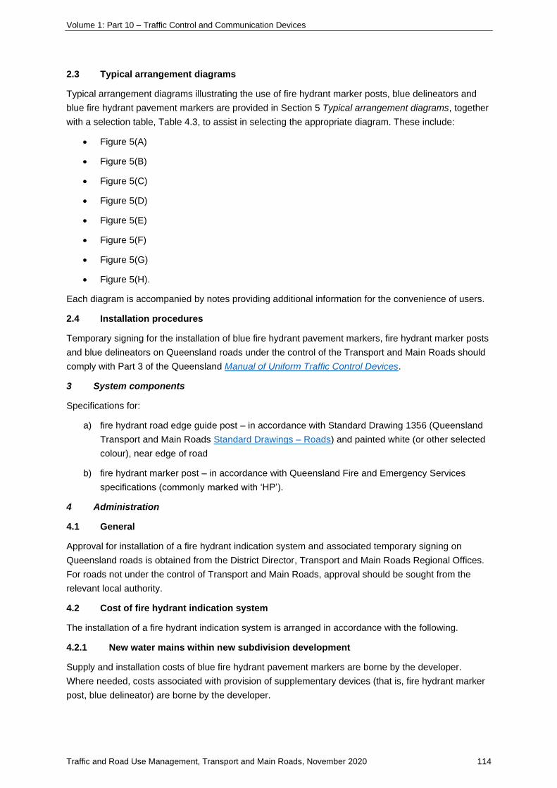
Volume 1: Part 10 – Traffic Control and Communication Devices
Traffic and Road Use Management, Transport and Main Roads, November 2020 114
2.3 Typical arrangement diagrams
Typical arrangement diagrams illustrating the use of fire hydrant marker posts, blue delineators and
blue fire hydrant pavement markers are provided in Section 5 Typical arrangement diagrams, together
with a selection table, Table 4.3, to assist in selecting the appropriate diagram. These include:
• Figure 5(A)
• Figure 5(B)
• Figure 5(C)
• Figure 5(D)
• Figure 5(E)
• Figure 5(F)
• Figure 5(G)
• Figure 5(H).
Each diagram is accompanied by notes providing additional information for the convenience of users.
2.4 Installation procedures
Temporary signing for the installation of blue fire hydrant pavement markers, fire hydrant marker posts
and blue delineators on Queensland roads under the control of the Transport and Main Roads should
comply with Part 3 of the Queensland Manual of Uniform Traffic Control Devices.
3 System components
Specifications for:
a) fire hydrant road edge guide post – in accordance with Standard Drawing 1356 (Queensland
Transport and Main Roads Standard Drawings – Roads) and painted white (or other selected
colour), near edge of road
b) fire hydrant marker post – in accordance with Queensland Fire and Emergency Services
specifications (commonly marked with ‘HP’).
4 Administration
4.1 General
Approval for installation of a fire hydrant indication system and associated temporary signing on
Queensland roads is obtained from the District Director, Transport and Main Roads Regional Offices.
For roads not under the control of Transport and Main Roads, approval should be sought from the
relevant local authority.
4.2 Cost of fire hydrant indication system
The installation of a fire hydrant indication system is arranged in accordance with the following.
4.2.1 New water mains within new subdivision development
Supply and installation costs of blue fire hydrant pavement markers are borne by the developer.
Where needed, costs associated with provision of supplementary devices (that is, fire hydrant marker
post, blue delineator) are borne by the developer.

Volume 1: Part 10 – Traffic Control and Communication Devices
Traffic and Road Use Management, Transport and Main Roads, November 2020 115
4.2.2 Existing water mains
The local authority is responsible for all costs associated with the provision of a fire hydrant indication
system described in this supplement (in lieu of an existing marking system), in conjunction with
existing water mains.
The installation of a fire hydrant indication system, or conversion of an existing marking system to this
system, should be undertaken on an area- (or sub-area) wide basis, as negotiated with the
Queensland Fire and Emergency Services.
4.2.3 Maintenance of fire hydrant indication system
The local authority is responsible for continuing inspection and maintenance of fire hydrant indication
systems described in this supplement. This includes hydrant location records. Upon request,
Transport and Main Roads would carry out minor maintenance or repairs on Queensland roads, for
example, replacement of blue fire hydrant pavement markers. The cost applied is an estimate of the
actual cost of the repairs or replacement.
Where roadworks affect part of the fire hydrant indication system, Transport and Main Roads would
ensure replacement of the part(s) at its cost.
4.3 Removal
Discussions are to be held with the Queensland Fire Service, prior to the removal of devices installed
under the provisions of this supplement. Consideration for removal of such devices would be given
where:
i) the site is affected by temporary roadworks, or
ii) the site is subject to permanent improvements to the road system, for example, construction of
an overpass.
Table 4.3 – Fire hydrant marker selection table
Road type Description Figure selection
Unsealed road (gravel, dirt, sand)
two-lane, two--way road 1
Sealed road (without pavement marking)
two-lane, two-way road
− rural
− urban
2
3
Sealed road (with pavement marking)
two-lane, two-way road
multi-lane road
divided road
− narrow median
− wide median
4
5
6
7
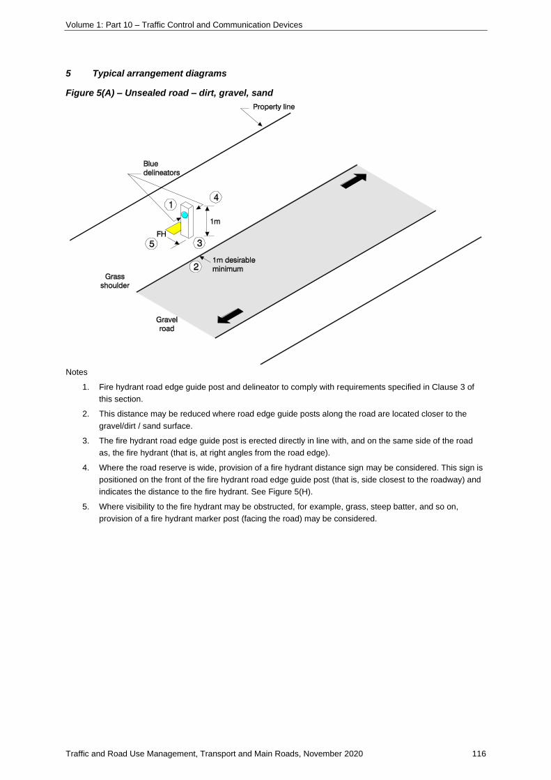
Volume 1: Part 10 – Traffic Control and Communication Devices
Traffic and Road Use Management, Transport and Main Roads, November 2020 116
5 Typical arrangement diagrams
Figure 5(A) – Unsealed road – dirt, gravel, sand
Notes
1. Fire hydrant road edge guide post and delineator to comply with requirements specified in Clause 3 of
this section.
2. This distance may be reduced where road edge guide posts along the road are located closer to the
gravel/dirt / sand surface.
3. The fire hydrant road edge guide post is erected directly in line with, and on the same side of the road
as, the fire hydrant (that is, at right angles from the road edge).
4. Where the road reserve is wide, provision of a fire hydrant distance sign may be considered. This sign is
positioned on the front of the fire hydrant road edge guide post (that is, side closest to the roadway) and
indicates the distance to the fire hydrant. See Figure 5(H).
5. Where visibility to the fire hydrant may be obstructed, for example, grass, steep batter, and so on,
provision of a fire hydrant marker post (facing the road) may be considered.
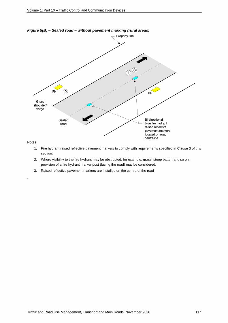
Volume 1: Part 10 – Traffic Control and Communication Devices
Traffic and Road Use Management, Transport and Main Roads, November 2020 117
Figure 5(B) – Sealed road – without pavement marking (rural areas)
Notes
1. Fire hydrant raised reflective pavement markers to comply with requirements specified in Clause 3 of this
section.
2. Where visibility to the fire hydrant may be obstructed, for example, grass, steep batter, and so on,
provision of a fire hydrant marker post (facing the road) may be considered.
3. Raised reflective pavement markers are installed on the centre of the road
.

Volume 1: Part 10 – Traffic Control and Communication Devices
Traffic and Road Use Management, Transport and Main Roads, November 2020 118
Figure 5(C) – Sealed road – without pavement marking (urban areas)
Notes
1. Fire hydrant raised reflective pavement markers to comply with requirements specified in Clause 3 of this
section.
2. Raised reflective pavement markers are installed on the centre of the road.
3. Where visibility to the fire hydrant may be obstructed, for example, grass, steep batter, and so on,
provision of a fire hydrant marker post (facing the road) may be considered.
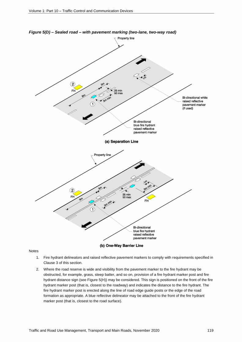
Volume 1: Part 10 – Traffic Control and Communication Devices
Traffic and Road Use Management, Transport and Main Roads, November 2020 119
Figure 5(D) – Sealed road – with pavement marking (two-lane, two-way road)
Notes
1. Fire hydrant delineators and raised reflective pavement markers to comply with requirements specified in
Clause 3 of this section.
2. Where the road reserve is wide and visibility from the pavement marker to the fire hydrant may be
obstructed, for example, grass, steep batter, and so on, provision of a fire hydrant marker post and fire
hydrant distance sign (see Figure 5(H)) may be considered. This sign is positioned on the front of the fire
hydrant marker post (that is, closest to the roadway) and indicates the distance to the fire hydrant. The
fire hydrant marker post is erected along the line of road edge guide posts or the edge of the road
formation as appropriate. A blue reflective delineator may be attached to the front of the fire hydrant
marker post (that is, closest to the road surface).

Volume 1: Part 10 – Traffic Control and Communication Devices
Traffic and Road Use Management, Transport and Main Roads, November 2020 120
Figure 5(D) (cont.) – Sealed road – with pavement marking (two-lane, two-way road)
Notes
1. Fire hydrant delineators and raised reflective pavement markers to comply with requirements specified in
Clause 3 of this section.
2. Where the road reserve is wide and visibility from the pavement marker to the fire hydrant may be
obstructed, for example, grass, steep batter, and so on, provision of a fire hydrant marker post and fire
hydrant distance sign (see Figure 5(H)) may be considered. This sign is positioned on the front of the fire
hydrant marker post (that is, closest to the roadway) and indicates the distance to the fire hydrant. The
fire hydrant marker post is erected along the line of road edge guide posts or the edge of the road
formation as appropriate. A blue reflective delineator may be attached to the front of the fire hydrant
marker post (that is, closest to the road surface).

Volume 1: Part 10 – Traffic Control and Communication Devices
Traffic and Road Use Management, Transport and Main Roads, November 2020 121
Figure 5(E) – Sealed road – multi-lane road
Notes
1. Fire hydrant delineators and raised reflective pavement markers to comply with requirements specified in
Clause 3 of this section.
2. For multi-lane, undivided roads where one-way or two-way barrier lines are used, refer to Figure 5(D) for
placement of fire hydrant raised reflective pavement markers and delineators.
3. Where the road reserve is wide and visibility from the pavement marker to the fire hydrant may be
obstructed, for example, grass, steep batter, and so on, provision of a fire hydrant marker post (that is,
closest to the roadway) and indicates the distance to the fire hydrant. The fire hydrant marker post is
erected along the line of road edge guide posts or the edge of the road formation as appropriate. A blue
reflective delineator may be attached to the front of the fire hydrant marker post (that is, closest to the
road surface).

Volume 1: Part 10 – Traffic Control and Communication Devices
Traffic and Road Use Management, Transport and Main Roads, November 2020 122
Figure 5(F) – Sealed road – divided road (narrow median)
Notes
1. Fire hydrant delineators and raised reflective pavement markers to comply with requirements specified in
Clause 3 of this section.
2. For roads with more than two lanes of travel in one direction, a fire hydrant marker post (and delineators)
is erected in the median. In this case, fire hydrant pavement markers are not installed.
3. Where a New Jersey-type structural barrier forms the narrow median on roads with more than two lanes
of travel in one direction, a fire hydrant delineator (single-sided) is mounted on top of the New
Jersey-type barrier. Fire hydrant pavement markers are not used in this case.
4. Where the road reserve is wide and visibility from the pavement marker to the fire hydrant may be
obstructed, for example, grass, steep batter, and so on. provision of a fire hydrant marker post and fire
hydrant distance sign (see Figure 5(H)) may be considered. This sign is positioned on the front of the fire
hydrant marker post (that is, closest to the roadway) and indicates the distance to the fire hydrant. The
fire hydrant marker post is erected along the line of road edge guide posts or the edge of the road
formation as appropriate. A blue reflective delineator may be attached to the front of the fire hydrant
marker post (that is, closest to the road surface).
5. Where access to a fire hydrant is not available from the opposite carriageway (for example, vertical wall),
a fire hydrant pavement marker, or other indication, is not placed for that carriageway.
6. Where the road is a freeway or motorway (with fire hydrants located outside of the road reserve) and it is
desired to indicate the fire hydrant, a freeway fire hydrant distance sign (see Figure 5(H)) is attached to
the freeway fencing in lieu of the installation of a fire hydrant marker post. An indication of this type is
only provided where appropriate access to the hydrant is available for fire fighting vehicles.

Volume 1: Part 10 – Traffic Control and Communication Devices
Traffic and Road Use Management, Transport and Main Roads, November 2020 123
Figure 5(G) – Sealed road – divided road (wide median)
Notes
1. Fire hydrant delineators and raised reflective pavement markers to comply with requirements specified in
Clause 3 of this section.
2. For roads with more than two lanes or travel in one direction, a fire hydrant marker post (and delineators)
is erected in the median. In this case, fire hydrant pavement markers are not installed.
3. Where a New Jersey-type structural barrier is used on roads with more than two lanes of travel in
one direction, a fire hydrant delineator (single-sided) is mounted on top of the New Jersey-type barrier.
Fire hydrant pavement markers are not used in this case.
4. Where the road reserve is wide and visibility from the pavement marker to the fire hydrant may be
obstructed, for example, grass, steep batter, and so on, provision of a fire hydrant marker post and fire
hydrant distance sign (see Figure 5(H)) may be considered. This sign is positioned on the front of the fire
hydrant marker post (that is, closest to the roadway) and indicates and the distance to the fire hydrant.
The fire hydrant marker post is erected along the line of the road edge guide posts or the edge of the
road formation as appropriate. A blue reflective delineator may be attached to the front of the fire hydrant
marker post (that is, closest to the road surface).
5. Where access to a fire hydrant is not available from the opposite carriageway (for example, vertical wall),
a fire hydrant pavement marker, or other indication, is not placed for that carriageway.
6. Where the road is a freeway or motorway (with fire hydrants located outside of the road reserve) and it is
desired to indicate the fire hydrant, a freeway fire hydrant distance sign (see Figure 5(H)) is attached to
the freeway fencing in lieu of the installation of a fire hydrant marker post. An indication of this type is
only provided where appropriate access to the hydrant is available for fire fighting vehicle.

Volume 1: Part 10 – Traffic Control and Communication Devices
Traffic and Road Use Management, Transport and Main Roads, November 2020 124
Figure 5(H) – Fire hydrant indication signs

Volume 1: Part 10 – Traffic Control and Communication Devices
Traffic and Road Use Management, Transport and Main Roads, November 2020 125
6.8 Rumble strips
6.8.1 Types and application
6.8.1-1 Rumble strips
See Traffic and Road Use Management manual, Volume 2 Guide to Road Safety Part 5 Road Safety
for Rural and Remote Areas.

Volume 1: Part 10 – Traffic Control and Communication Devices
Traffic and Road Use Management, Transport and Main Roads, November 2020 126
7. Guide posts and delineators
7-1 Bicycle lane separation devices
1 Purpose and scope of this Supplement
This supplement has been prepared to provide guidance on preferred treatments and design
characteristics of bicycle lane separation devices.
Austroads Guide to Road Design Part 6 Roadside Design, Safety and Barriers, Section 6.5 addresses
road system barriers but adjacent to off-road shared paths rather than for on-road bicycle lanes.
Austroads Guide to Road Design Part 3 Geometric Design Section 4.8 discusses separated bicycle
lanes, protected bicycle lanes and supplementary treatments but does not provide specific safety
design details about the separation treatment. Transport and Main Roads guideline Selection and
design of cycle tracks also discuss separation treatments, including widths but does not provide
guidance on separation device design considerations.
1.1 Background
Transport and Main Roads supports the implementation of on-road separation between cyclists and
motorists. There is currently limited design guidance, however, on how to best implement these
separation treatments and to ensure new hazards are not created for cyclists. A number of incidents
have been reported (refer to Section 4.1 Case studies) that emphasise the importance of ensuring
separation treatments are not hazards in their own right.
While separation devices increase the lateral separation between cyclists and motorists, research
confirms that some devices and/or treatments are more effective than others.
The degree, and type of separation varies, with separation being provided through road markings,
vertical separation, physical barriers, and a combination of devices. This supplement provides a
recommendation of preferred separation devices which are suitable for use alongside on-road bicycle
lanes.
1.2 Related documents
This supplement should be read in conjunction with the following guidelines:
• Austroads Guide to Road Design:
− Part 3 Geometric Design
− Part 6 Roadside Design, Safety and Barriers
− Part 6A Pedestrian and Cyclist Paths
• Austroads Cycling Aspects of Austroads Guides
• Queensland Manual of Uniform Traffic Control Devices:
− Part 2 Traffic Control Devices for General Use
− Part 9 Bicycle Facilities
• Transport and Main Roads guideline Selection and design of cycle tracks.

Volume 1: Part 10 – Traffic Control and Communication Devices
Traffic and Road Use Management, Transport and Main Roads, November 2020 127
The documents listed below have been referenced in this supplement but are not listed in related
documents:
• Cardno prepared for Department of Transport and Main Roads, Review of Engineering
Treatments for the Separation of Bicycle Lanes, March 2016
• CARRS-Q prepared for Department of Transport and Main Roads, Separated Bicycle Lanes –
review of literature, February 2016
• Queensland Government (Department of Transport and Main Roads), Fact Sheet: Separation
Devices on Bicycle Lanes, September 2016.
2 Preferred separation device
2.1 Device configuration
The preferred separation device configuration is a vertical delineation device on a separation kerb,
within a pavement marked buffer. The design aspects of the preferred separation device are
detailed in Figure 2.1(A) – Key features of preferred treatment and Table 2.1 – Preferred separation
device design attributes.
Figure 2.1(A) – Key features of preferred treatment

Volume 1: Part 10 – Traffic Control and Communication Devices
Traffic and Road Use Management, Transport and Main Roads, November 2020 128
Table 2.1 – Preferred separation device design attributes
Preferred safety
design features Function Considerations
Separation kerb Provides a safe mounting for vertical delineators and a tactile deterrent to vehicle encroachment.
To optimise safety outcomes, the preferred separation device must have the following characteristics:
• conspicuous through use of contrasting colours and inclusion of fluorescent and retroreflective elements
• slip-resistant wet pendulum >65BPN
• semi-mountable on the bicycle side, not incorporating a vertical lip (refer Transport and Main Roads Standard Drawing 1033); a barrier profile may be appropriate on the motor vehicle side to reduce motor vehicle encroachment
• continuous treatments are preferred compared to short sections of discrete devices; they should be sufficiently long that they are legible on approach (for example, install the kerbs on the approach to corner of conflict zone such that they reinforce to motorists the desired travel path in their own lane).
• Breaks in the device should be included to remove a ‘debris trap’ and overland flow / road drainage should not be significantly affected.
• Drainage gaps shall incorporate sloped ends no steeper than 1 in 4 on the leading edge.
• Avoid short sections of separation kerb as it may appear unexpectedly to cyclists.
• Regular monitoring and clearing of debris build-up in the bicycle lane and near the device is required.
• The vertical height of the device makes it difficult for vehicles to mount it at reasonable speed and/or comfort and is therefore only suitable where there is no demand for vehicles to cross the device (for example, to access car parking or driveways).
• Where access to driveways needs to be maintained, fully-mountable separation kerbs may be used in these sections only (as illustrated in Figure 2.1(B).

Volume 1: Part 10 – Traffic Control and Communication Devices
Traffic and Road Use Management, Transport and Main Roads, November 2020 129
Preferred safety
design features Function Considerations
Vertical delineation device
Improves conspicuity, reduces the likelihood of bicycle wheel strikes and complements the vehicle encroachment deterrent provided by the separation kerb.
• These are effective in improving the legibility and visibility of the installed physical separation kerb.
• These are very effective in improving rider safety. They are more effective when installed with other devices (for example, separation kerb) rather than directly into the road surface.
• The height should be the equivalent of a road edge guide post.
• The device should be installed at the front face of the treatment and at regular intervals.
• Additional / more frequently spaced devices may be required based on site characteristics such as horizontal alignment or where there is a lack of or limited street lighting.
• Larger gaps in spacing may be considered where there is a need for vehicles to cross the device.
• A disadvantage of this device is the potential for impact damage and associated frequent maintenance / replacement costs.
Pavement marked buffer around the separation kerb
Improves delineation and provides the required offset to vehicles and bicycles from the separation device.
Refer to offset requirements to travel lanes specified in the Road Planning and Design Manual and Austroads guides.

Volume 1: Part 10 – Traffic Control and Communication Devices
Traffic and Road Use Management, Transport and Main Roads, November 2020 130
Figure 2.1(B) – Example of mountable separation kerb for driveway access
2.2 Site design considerations
Site design aspects to be considered when installing bicycle lane separation devices include:
• bicycle lane width and the potential for the device to hinder passing or overtaking within the
bicycle lane
• the type of cyclist likely to use the bicycle lane:
− groups or individuals
− children or adults, and
− level of experience
• the likelihood of motor vehicle encroachment, especially at:
− feeder bicycle lanes to advanced storage areas or advanced stop boxes
− horizontal curves
− weaving situations, and
− intersection auxiliary lanes
• traffic volumes and proportion of heavy vehicles / buses
• locations where there is high vehicle or pedestrian demand across / through the bicycle lane:
− strong pedestrian desire line along or across the bicycle lane
− kerbside bus stops (consider bus frequency)
− kerbside car parking (consider turnover rates and if it is reconfigurable), and
− driveways at high vehicle trip generators.
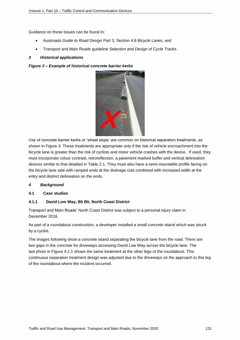
Volume 1: Part 10 – Traffic Control and Communication Devices
Traffic and Road Use Management, Transport and Main Roads, November 2020 131
Guidance on these issues can be found in:
• Austroads Guide to Road Design Part 3, Section 4.8 Bicycle Lanes, and
• Transport and Main Roads guideline Selection and Design of Cycle Tracks.
3 Historical applications
Figure 3 – Example of historical concrete barrier kerbs
Use of concrete barrier kerbs or ‘wheel stops’ are common on historical separation treatments, as
shown in Figure 3. These treatments are appropriate only if the risk of vehicle encroachment into the
bicycle lane is greater than the risk of cyclists and motor vehicle crashes with the device. If used, they
must incorporate colour contrast, retroreflection, a pavement marked buffer and vertical delineation
devices similar to that detailed in Table 2.1. They must also have a semi-mountable profile facing on
the bicycle lane side with ramped ends at the drainage cuts combined with increased width at the
entry and distinct delineation on the ends.
4 Background
4.1 Case studies
4.1.1 David Low Way, Bli Bli, North Coast District
Transport and Main Roads’ North Coast District was subject to a personal injury claim in
December 2016.
As part of a roundabout construction, a developer installed a small concrete island which was struck
by a cyclist.
The images following show a concrete island separating the bicycle lane from the road. There are
two gaps in the concrete for driveways accessing David Low Way across the bicycle lane. The
last photo in Figure 4.1.1 shows the same treatment at the other legs of the roundabout. This
continuous separation treatment design was adjusted due to the driveways on the approach to this leg
of the roundabout where the incident occurred.

Volume 1: Part 10 – Traffic Control and Communication Devices
Traffic and Road Use Management, Transport and Main Roads, November 2020 132
The smaller concrete island was hit by a cyclist who was injured, and subsequently made a personal
injury claim against Transport and Main Roads. The concrete island has now been removed.
Lessons learnt: Smaller non-continuous sections of separation devices can be hazardous
particularly when installing next to minimum width bicycle lanes. It is preferable to not install short
sections of separation; however, if these are to be installed, further delineation of the potential
hazard should be incorporated into the design.
Figure 4.1.1 – David Low Way: Showing concrete islands separating the bicycle lane from the
road
(Source: Google Street View)
4.1.2 Captain Cook Highway, Cairns, Far North Queensland region
A bicycle lane separation treatment was funded by the Safer Roads Sooner program on the Captain
Cook Highway in Cairns. It sought to provide a physical separation between cyclists and vehicles on a
road with high traffic volumes and speeds and a high proportion of heavy vehicles. The funding
business case drew upon a Coroner’s findings into a death that had occurred at this location.
The initial treatment (2009) used a low-height plastic kerb and is shown in Figure 4.1.2(A).

Volume 1: Part 10 – Traffic Control and Communication Devices
Traffic and Road Use Management, Transport and Main Roads, November 2020 133
Figure 4.1.2(A) – Captain Cook Highway: 2009 separation treatment (plastic kerb with vertical
delineators)
Brisbane City Council have used this profile at the separated cycle facility in George Street
(Figure 4.1.2(B)), and Transport and Main Roads has installed it on Gympie Road at Kedron Park
Road southbound (Figure 4.1.2(C)).
At all locations, and specifically at the Captain Cook Highway, there have been maintenance issues
with vehicles striking the kerb (the pinning mechanisms failed on repeated occasions) and the
delineator posts were frequently damaged.
Figure 4.1.2(B) – George Street, Brisbane (plastic kerb with vertical delineators)

Volume 1: Part 10 – Traffic Control and Communication Devices
Traffic and Road Use Management, Transport and Main Roads, November 2020 134
Figure 4.1.2(C) – Gympie Road at Kedron Park Road southbound, Kedron Park (plastic kerb
with vertical delineators)
Considering the maintenance issues and the need to further discourage heavy vehicles from entering
the bicycle lane, the Far North Queensland region submitted a Safer Roads Sooner funding case to
replace it with a concrete, back-to-back barrier kerb, which is still in place (Figure 4.1.2(D)).

Volume 1: Part 10 – Traffic Control and Communication Devices
Traffic and Road Use Management, Transport and Main Roads, November 2020 135
Figure 4.1.2(D) – Captain Cook Highway: current separation treatment (concrete kerb)
Design changes included amending the bicycle lane openings to assist in smooth bicycle flow paths
and 300 mm vertical delineation devices were installed; however, as per the 2009 project, these were
also struck by heavy vehicles’ rear wheels and became a maintenance issue (see Figure 4.1.2(D)
image with marker lying flat on the ground in front of kerb).
While this has been considerably more effective in achieving the primary goal of preventing vehicles
from entering the bicycle lane, there are design elements that could be improved to make it more
‘cycle friendly’, notably the steep leading edges at the drainage breaks, the entering / exiting
alignment, the width at the entry and improved delineation of the end (which would benefit both
cyclists and drivers).
The challenge at the Captain Cook Highway roundabouts is to keep vehicles out of the bicycle lane
but ensure any new risks for cyclists are not introduced. The barrier kerb on the traffic side appears to

Volume 1: Part 10 – Traffic Control and Communication Devices
Traffic and Road Use Management, Transport and Main Roads, November 2020 136
have effectively reduced the ‘hit by truck’ risk but has introduced other hazards that should be able to
be mitigated with some design modifications.
Lessons learnt: The plastic kerb was not suitable for the high traffic and truck volumes (and in
particular, the B-double sugarcane hauling trucks) experienced at the Captain Cook Highway
roundabouts. A more robust treatment was necessary to keep vehicles out of the bicycle lane.
Further improvements could still be considered to reduce risks to cyclists by introducing a
semi-mountable profile on the cyclist side with ramped ends at the drainage cuts, combined with
increased width at the entry and distinct delineation on the ends, colour contrast, retroreflection,
and a pavement marked buffer and vertical delineation devices. In addition, a cyclist rail / post
could be included to assist cyclists checking for turning vehicles from behind at GIVE WAY
locations.
4.2 Separation device audit
The following table details separation devices currently in place and the findings of the assessment of
their suitability as separation treatments for on-road bicycle lanes. This assessment informed the
definition of the preferred bicycle lane separation treatment outlined in Section 2.

Volume 1: Part 10 – Traffic Control and Communication Devices
Traffic and Road Use Management, Transport and Main Roads, November 2020 137
Table 4.2 – Types of separation devices and suitability audit
Device Examples Assessment findings
Pavement markings
Painted buffer (various line marking arrangement and widths)
• Provision of raised reflective pavement markers (RRPMs) also assisted with this improved perception of safety.
• Limited effectiveness in reducing vehicle encroachment.
Painted 1m chevron traffic island with rumble bars (Chinderah Bay Road)
Painted 2m chevron traffic island with RRPMs at bend (Bennetts Road)
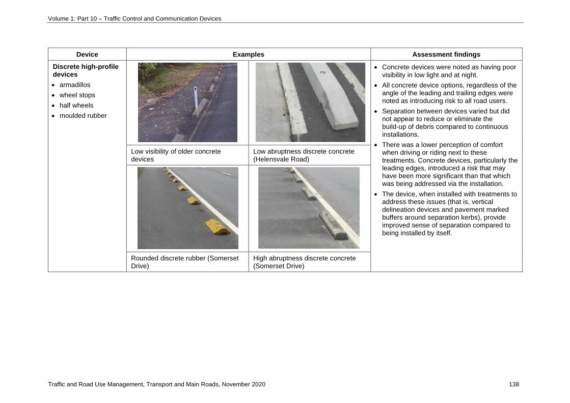
Volume 1: Part 10 – Traffic Control and Communication Devices
Traffic and Road Use Management, Transport and Main Roads, November 2020 138
Device Examples Assessment findings
Discrete high-profile devices
• armadillos
• wheel stops
• half wheels
• moulded rubber
• Concrete devices were noted as having poor visibility in low light and at night.
• All concrete device options, regardless of the angle of the leading and trailing edges were noted as introducing risk to all road users.
• Separation between devices varied but did not appear to reduce or eliminate the build-up of debris compared to continuous installations.
• There was a lower perception of comfort when driving or riding next to these treatments. Concrete devices, particularly the leading edges, introduced a risk that may have been more significant than that which was being addressed via the installation.
• The device, when installed with treatments to address these issues (that is, vertical delineation devices and pavement marked buffers around separation kerbs), provide improved sense of separation compared to being installed by itself.
Low visibility of older concrete devices
Low abruptness discrete concrete (Helensvale Road)
Rounded discrete rubber (Somerset Drive)
High abruptness discrete concrete (Somerset Drive)

Volume 1: Part 10 – Traffic Control and Communication Devices
Traffic and Road Use Management, Transport and Main Roads, November 2020 139
Device Examples Assessment findings
Discrete low / medium profile separators
• audio tactile line markings (ATLMs)
• retroreflective pavement markers
• Riley kerb
• low profile rumble bars
• Studies found that a significant proportion of vehicles travel over the ATLM devices and into the adjacent bicycle lane.
• Typically, the ATLM device is not an effective deterrent for motorists travelling at low speeds (approx. 60 km/h) and does not reinforce or increase separation between vehicles and cyclists.
• Some versions of rumble bars have a relatively high edge and could potentially destabilise a cyclist, should they meet the device.
• In some instances (for example, low-profile longitudinal humps), the low vertical profile could be almost indistinguishable in look or function to surface paint. These devices may prove ineffective as a deterrent to motorists given the very low profile. Additionally, cyclists may not be able to distinguish the device as being slightly raised and may inadvertently ride over it, not expecting there to be a difference in level or surface texture.
• Overall, these devices had a limited effect in reducing the number of vehicle encroachments into an adjacent bicycle lane and were not conspicuous enough.
Vehicle encroachment over ATLM (Bennetts Road)
Low profile rubber rumble bar with RRPM (Chinderah Bay Road)
Low profile longitudinal humps (Bridge Street, Mackay)
High profile rumble bar (creating a medium profile separator)

Volume 1: Part 10 – Traffic Control and Communication Devices
Traffic and Road Use Management, Transport and Main Roads, November 2020 140
Device Examples Assessment findings
Vertical separators
• flexible guide posts
• lane divider flap
• traffic cones
• low impact smart bollard
• plastic flexible bollards
Guide posts can be prone to regular and major damage depending on their location, proximity to the edge of traffic, and fixing / mounting type. Guide posts installed on top of concrete barriers or as an integrated component of a separation kerb are better alternatives based on consideration of the following:
• They appear less prone to initial damage compared to isolated guide post installations.
• When damaged, any remnant part of the guide post fixed to the surface (including the mounting plate) will not be located at-grade, itself becoming an unintended hazard for riders.
• When damaged, there appears an improved chance that some parts of the device mount may be contained within the longitudinal separator.
• Plastic bollard devices are retrofittable and relatively cheap, short enough to not catch on a cyclist’s handlebar and are reflective; however, they can be more prone to vandalism and regular damage by collision.
Damaged delineation post (Tweed Valley Way)
Plastic bollard device (Grey St)
Damaged (leaning) bi-directional guide posts (George Street)
Delineation post on top of concrete barrier (Helensvale Road)

Volume 1: Part 10 – Traffic Control and Communication Devices
Traffic and Road Use Management, Transport and Main Roads, November 2020 141
Device Examples Assessment findings
Separation kerbs
• caterpillar safe cycle (new product and as yet untested)
• rubber separation kerb
• rubber lane maker
• pre-cast concrete
• The rubber devices were robust and generally did not suffer catastrophic failure. Longer-term issues including UV degradation, device separation and cracking are common within an approximate four–six-year post-installation period, depending on site exposure and traffic characteristics.
• The continuous concrete kerb device is very robust; however, as these treatments age, their visibility becomes limited, particularly in low light or darkness. The dimension of the vertical face from the road surface is higher than the rubber device. The profile of the concrete kerb is likely required to reduce edges chipping off. There is the potential for the more significant edge dimension to destabilise a cyclist if he or she was involved in an acute collision with the device.
• Skid resistance needs to be verified.
Caterpillar kerb Rubber separation kerb (George St)
Pre-cast concrete (Maryborough Street – 20+ years old)

Volume 1: Part 10 – Traffic Control and Communication Devices
Traffic and Road Use Management, Transport and Main Roads, November 2020 142
Device Examples Assessment findings
Safety barriers (>150mm height)
• pre-cast concrete
• water filled
• Concrete barriers >150 mm high are typical installations on higher speed road environments, designed to redirect out-of-control vehicles. In this situation, a higher level of separation is preferable.
• The devices are installed as interconnected modules which make them difficult to locate within an existing road cross-section in a retrofit situation.
• They are also less likely to conform to medium-high radius turns, given their fixed characteristics.
• Water filled barriers are typical installations in temporary road works situations and are designed to be used as containment fences or as delineation devices. Similar to the pre-cast concrete barriers, these devices are installed as interconnected modules. Their width would make them difficult to locate within an existing road cross-section in a retrofit situation. The devices can be connected to form medium radius curves, unlike concrete barriers.
• A smaller form of device with a lower risk profile is preferred for retrofit situations and lower speed and traffic volume situations.
Pre-cast concrete with safety fencing Water filled safety barriers

Volume 1: Part 10 – Traffic Control and Communication Devices
Traffic and Road Use Management, Transport and Main Roads, November 2020 143
Device Examples Assessment findings
Planter boxes
• plastic / rubber
• pre-cast concrete
• raised gardens
• Planter boxes are large non-frangible devices where the mass and scale of the treatment could represent a hazard to motorists and cyclists on roads that have posted speed limits of 60 km/h or higher.
• The size (width) typical of planter boxes would also make it difficult to locate them within an existing road cross-section in a retrofit situation.
• The available research does not specifically reference planter boxes. The research is clear that any form of separation would deliver perceived and objective benefits to / for riders; therefore, a smaller form of a separation device that has a lower risk profile is preferred. FEMA 430 Section 4.4.2 discusses the use of crash-rated bollards concealed in planters.
• Advantages of these treatments is that they are much more aesthetically pleasing and can be preferable when installed as part of an overall streetscaping / greening / calming project for a particular precinct.
Plastic / rubber planter box Pre-cast concrete planter box
5 Further information
For further information on this supplement, please contact:
Transport and Main Roads – Engineering & Technology Branch
Email: [email protected]

Volume 1: Part 10 – Traffic Control and Communication Devices
Traffic and Road Use Management, Transport and Main Roads, November 2020 144
10 Communication devices
10.2 Technologies and applications
10.2-1 Implementation of internet-enabled video cameras
1 Introduction
This is a supplement to Section 10.2 of the Austroads Guide to Traffic Management Part 10 which
specifies practice specific to Queensland state-controlled roads.
The objective of this supplement is to provide guidance in relation to providing internet-enabled
cameras for the purpose of traveller information.
2 Key considerations
Before choosing a technology or proposing sites for internet-enabled cameras, the following key
considerations are essential:
• purpose
• ensuring privacy
• signage
• copyright requirements
• site and maintenance
• hardware and software, and
• security.
3 Purpose
The purpose of internet-enabled cameras is to provide traveller information to the public. In addition to
providing traffic conditions, internet-enabled cameras may have a role in reporting specific road
conditions (for example, a camera that provides traveller information in a remote area may monitor a
potential flood area).
The images should:
• be wide-angle images not displaying detail but providing an overall view of the traffic, road and
weather conditions that may affect travel
• meet all privacy requirements, and
• refresh at an appropriate rate so that motorists can understand the current traffic flow or road
condition.
Volume 1: Part 10 – Traffic Control and Communication Devices
Traffic and Road Use Management, Transport and Main Roads, November 2020 145
4 Ensuring privacy
The privacy rights of the general public shall be maintained. All images broadcast onto the internet
must comply with Queensland Government privacy policies.
Images that are not suitable for the public include but are not limited to:
• police activity
• incidents
• views of adjacent private property, and
• identification of people or vehicles.
Measures to ensure that images are suitable are as follows:
• using special-purpose internet-enabled cameras that have wide-angled lenses and are
suitably located
• displaying images with reduced resolution, making it impossible to interpret specific detail (for
example, vehicle registration details and identification of people), and
• providing physical ‘block outs’ built in to the camera equipment to limit viewing areas adjacent.
5 Copyright
All images shall be time and date stamped along with the relevant departmental branding.
6 Site and maintenance
6.1 Downtime and availability
Internet-displayed images should be reliable and accurate to reduce downtime and maintain public
confidence.
6.2 Access
Camera and associated hardware should be easily accessible for maintenance (refer to the
department’s Road Planning and Design Manual 2nd edition Volume 5 Intelligent Transport Systems).
6.3 Site selection
Consideration to the following is required prior to selecting a suitable site:
• traffic conditions
• road access and condition monitoring (for example, flood monitoring)
• vantage points
• privacy
• communications and power, and
• maintenance access.

Volume 1: Part 10 – Traffic Control and Communication Devices
Traffic and Road Use Management, Transport and Main Roads, November 2020 146
6.3.1 Traffic conditions
The intent of the images is to assist in informing how the current conditions (both traffic flow and
weather conditions) will affect motorists' travel.
Cameras should be installed at locations determined to have the potential to affect traffic flow.
Examples of these locations are as follows:
• intersections with high peak volumes
• areas of the road network that suffer regular congestion and/or incidents
• areas of the road network that suffer congestion due to planned events
• areas of the road network undergoing significant road works and where delays to motorists
are expected (for example, portable camera sites should be considered where applicable at
road work sites), and
• important intersections or roadways whereby traffic images will provide useful traveller
information, including potential flood locations.
6.3.2 Communications and power
Internet-enabled cameras will need to be connected to a central location for coordinated distribution.
The connection must use suitable communications technologies, taking into consideration the camera
technology and refresh rate required.
In addition to communications, each camera will require a stable power source.
7 Hardware and software
To provide traffic images onto the internet, the following infrastructure is required:
• cameras and associated hardware
• communication hardware
• site hardware.
It is suitable to install internet-enabled cameras onto existing infrastructure.
8 Security
Internet-enabled camera images should be from a secure or trusted source (for example, the
Transmax – ITS Network Distribution server (DISTRO), or a verified local government contact or
system) and then delivered to the QldTraffic service.

Volume 1: Part 10 – Traffic Control and Communication Devices
Traffic and Road Use Management, Transport and Main Roads, November 2020 147
Appendix C Abbreviations for use on variable message signs
C-1 Abbreviations for use in Queensland on variable message signs
Table C-1 – Approved Queensland-specific variants – abbreviations
Word Abbreviation
Emergency EMERGENCY
Highway HWY
Maintenance MTCE
Motorway MWY
Intersection INTRSECT
Holidays HOLS

Volume 1: Part 10 – Traffic Control and Communication Devices
Traffic and Road Use Management, Transport and Main Roads, November 2020 148
Appendix D Variable message signs statements
Appendix D.1 Recommended variable message signs problem statements
D.1-1 Approved Queensland-specific variants – problem statements
Problem Statement
CONGESTION DUE TO CRASH (or INCIDENT) LANE BLOCKED
DANGER QUEUE
FLAGMAN ROAD UNDER WATER
FOG CONDITIONS
GRASS FIRE WHEN WET
HEAVY TRAFFIC SMOKE
HIGH CRASH ZONE SMOKE HAZARD AHEAD
HIGH WIND VEHICLE BROKEN / DOWN
Appendix D.2 Recommended variable message signs location statements
D.2-1 Approved Queensland-specific variants – location statements
Locations definers Position definers
EXIT RAMP AFTER
‘name’ TUNNEL RIGHT
ON RAMP LEFT
OFF RAMP CENTRE
T2LANE
T3LANE
TRANSIT LANE
‘street name’ TO ‘street name’
Appendix D.3 Recommended variable message signs effect statements
D.3-1 Approved Queensland-specific variants – effect statements
POLICE AHEAD
POLICE CONTROL AHEAD
QFRS AHEAD
QUEUE
SPEED CAMERA AHEAD
SPEED CAMERA NOW ACTIVE
TRAFFIC CONTROL AHEAD

Volume 1: Part 10 – Traffic Control and Communication Devices
Traffic and Road Use Management, Transport and Main Roads, November 2020 149
Appendix D.4 Recommended variable message signs attention statements
D.4-1 Approved Queensland-specific variants – attention statements
The attention statement ‘ALL TRAFFIC’ should only be used where drivers may reasonably expect the
message to apply only to a particular group of motorists.
The flashing attention statement CHILD ABDUCTION ALERT TUNE TO LOCAL RADIO can only be
used when QPS issue an amber alert direct to TMCs.
VISITORS T3 VEHICLES
T2 VEHICLES TRANSIT VEHICLES
Appendix D.5 Recommended variable message signs action statements
D.5-1 Approved Queensland-specific variants – action statements
CRASH AHEAD/DIVERSION IN PLACE REDUCE SPEED NOW
CRASH AHEAD/REDUCE SPEED WATCH FOR TRUCKS
SPEED LIMIT REDUCED

Volume 1: Part 10 – Traffic Control and Communication Devices
Traffic and Road Use Management, Transport and Main Roads, November 2020 150
Appendix E Generic message set
E-1 Approved Queensland-specific variants – generic messages
Screen 1 Screen 2
Line 1 Line 2 Line 3 Line 1 Line 2 Line 3
1 CRASH EXPECT DELAYS
2 CRASH PROCEED WITH CAUTION
3 CRASH DETOUR AHEAD
4 CRASH PREPARE TO STOP
5 CRASH MAJOR DELAYS
FIND ALTERNATE ROUTE
6 CRASH MAJOR DELAYS
PROCEED WITH CAUTION
7 CRASH MINOR DELAYS
PROCEED WITH CAUTION
