part 1v islands - traffic sign · part 1v islands - a.-general considerations section 4a-1...
TRANSCRIPT
Part 1V
ISLANDS -
A.-GENERAL CONSIDERATIONS
Section 4A-1 Functions of Islande
A traffic-control island is a defined area between traffic lanes , for control of vehicle movements or for pedestrian refuge. With-
in an intersection area, a median or an outer separation is con- sidered to be an island. An island may be designated by paint, raised bars, mushroom buttons, curbs, guideposts, pavement edge, or other devices. For the purposes of this Manual, an island includes not only the designated area but also all end protection and approach-end treatments.
It should be realized that islands constitute an integral part of the geometric design of streets and highways and should be included in overall projects for construction. At times, how- ever, an island may have to be installed at an existing intersection to improve or correct an outdated design. This Manual pri- marily treats the traffic-control characteristics of islands rather than their design features; however, certain minimum standards are suggested. The treatment of islands herein applies largely to urban and suburban installations which are usually located in relatively restricted roadway or intersection areas. For guides to street and highway design, including the design of islands, reference should be made to A Policy on Geornet?"ic Design of Rural Highways, 1954, and A Policy on A~te?.ial Highways in Urban Areas, 1957, both of which have been adopted and pub- lished by the American Association of State Highway official^.^^
4A-2 Classification
Islands may be classed functionally and physically as follows :
1. Pedestrian refuge islands (secs. 4B-1 to 7) . Loading islands are considered to be a special form of refuge islands (sec. 4B-7).
2. Traffic divisional islands (secs. 4C-1 to 6). 3. Traffic channelizing islands (secs. 4D-1 to 6 ) .
as Available from the American Association of State Highway Officials, 917 National Press r Building, Washington 4, D.C. ! i

Illustrations of refuge, divisional, and channelizing islands are shown in figures 4-1 to 4-3.
Pedestrian islands are provided to serve a s safety zones for the aid and protection of persons on foot. The right of a pedes- trian to occupy a pedestrian island in safety is commonly sus- tained by law. A safety zone is defined as an area within a roadway, officially set aside for the exclusive use of pedestrians, The Uniform Vehicle Code, (sec. 11-1304), prohibits a motor vehicle from entering a safety zone a t any time.
Figure 4-1. Pedestrian refuge island with walk-through crosmalk. Approach- end treatment consists of pavement markings and a reflectorized sign.
Figure 4-2. Turf median outlined by a mountable curb in a suburban a rm. , Approach-end treatment consists of pointed lines on the pavement, pointed , curb, and o reflectorired sign.
238

Traffic islands include all areas created for separating and directing vehicular traffic. They may be either channelizing or divisional. Divisional islands serve to divide- opposing or same-direction traffic streams that are usually through movements. Channelizing islands are designed to control and direct traffic move'ment, usually turning movements. i
Figure 4-3. Channelizing islands at a signalized Y-intersection. Concrete .curbs delineate the island edges. Mushroom buttons separate a left-turn lane from the through lanes.
Most islands serve two or all of these functions. Divisional islands a t intersections, for instance, nearly always serve as pedestrian refuge islands. Refuge islands located on an other-
/ wise undivided street also function as divisional islands. Except for features and criteria that apply to all islands, each function is discussed separately in this Manual.
PA-3 General Design Elements
The necessity for an island should be determined only by care- ful study, since it is placed in an area that would otherwise be available for vehicular traffic. The island design should be care- fully planned so that the shape of the island will conform to natural vehicular paths and so that a raised island will not consti- tute a hazard in the roadway. A judiciously placed island a t

an intersection on a wide street may eliminate the need for traffic signal control by channelizing traffic into orderly movements.
The island should be clearly visible a t all times and sufficiently in advance so that the motorist will not be surprised by its presence. The island should occupy the minimum of roadway space needed for its purpose and yet be of sufficient size to be noticeable so that motorists will not be likely to run over it, As governed by the design and traffic conditions, the delineation, illumination, reflectorization, signing, and marking for each , island should be as recommended in this Manual.
Size and shape.-Islands are generally either narrow and elon- gated or triangular in shape, are normally situated in areas of '
the roadway outside the planned vehicle paths, and are shaped and dimensioned as component parts of the street or intersection layout. The actual size differs as governed by site conditions, but the following minimum size requirements should be met to insure that the island will be large enough to command attention. For rural conditions any island should preferably be a t least 75 square feet in area, or a t least 50 square feet for very re- stricted conditions. For urban conditions where speeds are low, corresponding values are 50 and 35 square feet. The latter corresponds to a triangular island of about 6-foot dimension be- tween rounded ends on each leg. An elongated island with a minimum width of 4 feet should preferably be a t least 20 fee t , long, and in no case less than 12 feet.
Designation of wea.-The form or means of designating an island area varies, depending on its size, location, and function, i and also the character of the adjacent area, rural or urban. Generally, islands are delineated by one of the following methods: (1) raised and outlined by curbs and filled with pavement, turf, or other material; (2) formed by pavement markings, buttons, or raised bars on all-paved areas, used in urban districts where speeds are low and space is limited; or (3) unsurfaced, flush with the traveled way, sometimes supplemeilted by guideposts, stan-
I chions, or other delineators, used for large islands. Island areas , of minimum size should be designated by pavement markings, buttons, or raised bars. Small island areas should be designated
I by vertical curbs when used for pedestrian refuge or for the installation of traffic control devices. Large island areas should be designated by curbs, either mountable or vertical, or by color '
l
and texture contrast of vegetative cover, shrubs, mounded earth, guideposts, or signs, or any combination of these (figs. 4-2, 4-3, ' and 4-4).
Vertical curbs are designed with a face vertical or sloped a t
240
an angle less than 20" to the vertical, ordinarily unmountable by vehicles.
~ o u n t i b l e curbs are designed so that vehicles may cross with- out a severe jolt; usually with a sloping face at an angle between 20" and 60" from the vertical.
The type of curb used to bound an island is dictated by the needs of the situation, which vary according to vehicle speeds, pedestrian traffic, and island types and width. All curbs in the line of traffic flow should be painted yellow (sec. 2C-4). Islands on major streets in urban areas are usually bounded by 5- to 8-inch vertical curbs for the protection of pedestrians, signal and lighting standards, or other traffic control devices (figs. 4-1, 4-7, and 4-23). Whenever a barrier curb is not es- sential for traffic control or safety a mountable curb should be used. Curbed refuge and channelizing islands, and divisional islands where feasible, should be designed without curb-and-gutter sections adjacent to the islands so that they remain fully visible and roadway widths are unrestricted during periods of pavement surf ace drainage.
As noted in section 2A-5, raised bars or buttons are sometimes used to designate an island or part of an island (figs. 4-3, 4-4, and 4-10). They should not be used where they constitute an un- expected hazard. These devices should not project more than 1 to 3 inches above the pavement surface, so that any wheel
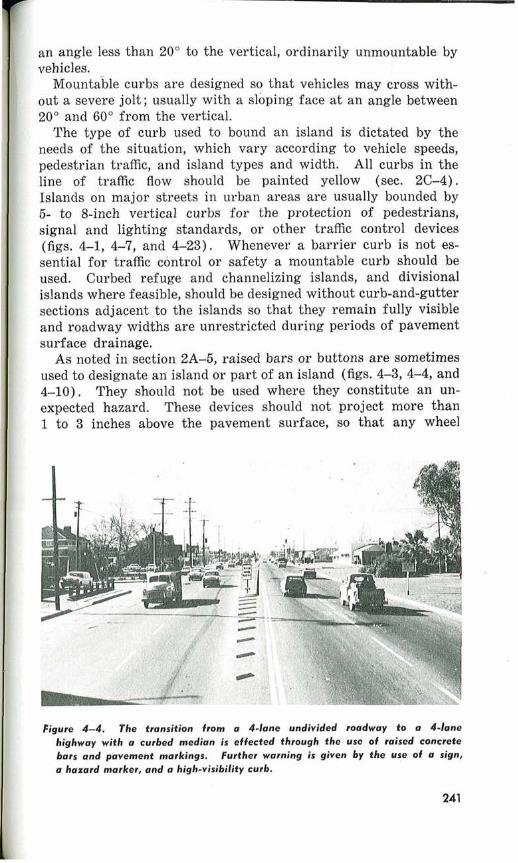
Figure 4-4. The transition from a 4-lane undivided roadway to a 4-lane highway with a curbed median is effected through the use of raised concrete bars and pavement markings. Further warning is given by the use of a sign, a hazard marker, and a high-visibility curb.

encroachment within the area will become obvious to thi vehicle driver without a resultant loss of control of the vehicle. A major disadvantage of these devices is that the spaces between them are difficult to keep clean. Pavement markings may be used effectively with raised bars or buttons to designate better the island area.
When an island is installed in an existing intersection or road- way, it is often necessary to provide additional roadway space for traffic movement,, since some of the original width is usurped by the width of the island. This usually can be accomplished by the simple expedient of prohibiting parking adjacent to and in the immediate vicinity of the island. As a general rule, parking adjacent to an island is undesirable and unsafe, as i ts effect is to destroy the geometric pattern for which the island is designed.
4A-4 Approach-End Treatment
The approach end of an island shall be carefully deeigned to 1 provide, for approaching traffic, a maximum degree of warning
of the presence of the island and a definite indication of the proper vehicle path or paths to he followed. This applies directly to the approach to all refuge and directional islands and to indi- vidual divisional islands, but is not applicable to island ends a t median openings on a divided street or highway.
Various methods of approach-end treatment have been used with satisfactory results, but experience does not yet justify complete standardization. Experimentation should be continued. In effective installations to date the motorist is warned of the island and guided around i t by one or by some combination of the following devices :
1. Pavement markings (secs. 2B-15, 17, 18). 2. Object markings (secs. 2C-2 to 4 ) .
I
I 3. Signs (secs. 1B-25, 1C-34). I 4. Reflecting devices (sec. 2D-2).
I 5. Flashing yellow beacons (sec. 3G-2, 3 ) . 6. Contrasting pavement colors or textures. 7. Raised bars, buttons, and median blocks (sec. 2A-5). 8. Illumination devices.
Although there is no standardization as to the type of approach- end treatment used, there are standards that should be applied
I for particular types. The standards of application are discussed I in the sections mentioned above and in sections 4A-3 and 4A-4. I The ends of islands first approached by traffic should he pre-
I ceded by a gradually widening marking or a conspicuously roughened strip on the roadway surface and designed so as to lead the vehicles into natural paths of travel in the desired direc-

tions along the island edge. The use of raised bars is often a preferable treatment in advance of curbed island noses. These devices should be combined to the extent practicable with other high-visibility indicators, such as reflectorized curbs, suitably reflectorized or illuminated signs located near the approach end, or reflectors mounted above the island (fig. 4-4).
At the beginning of a divisional or pedestrian refuge island which separates opposing traffic movements the island nose should be offset to the left, as faced by approaching traffic, the right curb of the island forming a diverging taper to deflect traffic toward the right. Where a channelizing or divisional island is introduced between two lanes of traffic moving in the same direction similar offsets should be used, to the extent that space permits, on each side of the nose to direct traffic into the separate roadways.
8.-REFUGE ISLANDS
Section 4B-1 Legal Authority
Refuge islands, being in the roadway, may be established only on the authority of the local or State highway officials having jurisdiction.
A model of legal authority for the establishment of refuge islands, or safety zones, is presented in the Model Traffic Ordi- nance (sec. 4-12) and authority for the exclusion of vehicular traffic from such islands is provided in the Uniform Vehicle Code (sec. 11-1304).
4B-2 Functions
The main function of a refuge island is to provide a place of safety for pedestrians who cannot cross the entire roadway width a t one time in safety because of changing traffic signals or on- coming traffic. In congested areas they also expedite vehicular traffic by permitting some vehicles to proceed without waiting for pedestrians to cross the entire roadway.
4B-3 Design Elemente
Refuge islands should be used in urban areas on exceptionally wide roadways or in large or irregularly shaped intersections where there is a considerable amount of pedestrian traffic and where heavy volumes of vehicular traffic make i t difficult and dangerous for pedestrians to cross. No refuge island should be placed where i t will leave less than two through lanes avail- able for traffic between i t and the adjacent curb or another island. However, a turning lane separated from the through

lanes by an island may be designed for a single traffic lane 4D-3 and fig. 4-5). Normally a refuge island should be cen on the median line of the roadway (fig. 4-1).
Figure 4-5. Walk-through pedestrian refuge island that also serves to separate a median lane from the through lanes. Approach-end treatment consists of pavement markings and high-visibility painted curb.
Refuge islands should not be located so as to create a hazard for motor vehicles (sec. 4A-3). I n areas with fast-moving vehicular traffic, islands not on the roadway centerline should be avoided. Streets with reverse-flow lanes require special con- sideration in determining island placement. Whenever heavy pedestrian traffic occurs on a street with vehicular traffic moving a t relatively high speed, consideration should be given to some additional form of pedestrian protection, such as a pedestrian- actuated traffic signal or a pedestrian grade separation.
In urban areas with slow-moving traffic and many pedestrians, a refuge island should desirably be provided a t an intersection with a one-way or two-way roadway six or more lanes in width. At signalized intersections refuge islands are used to expedite vehicular movements by provision of safety zones between dif- ferent traffic streams. Refuge islands may be required a t each intersection along a street. I n such case consideration should be given to providing a continuous median divider strip between intersections, as discussed in section 4C-3.
Sections 4A-3 and 4A-4 should be used as guides in the design of refuge islands. It is preferable that part of the island be a raised platform, outlined by barrier curbs, to afford pedestrians a greater sense of security. P a r t of the area at' the crosswalk desirably should be kept a t pavement level to facilitate use by

baby carriages, wheel chairs, and crippled or infirm persons. 1 1
Although it is better to have part of the raised platform project beyond the crosswalk on the side towards the intersection (figs. 4-1, 4-5), i t is permissible to stop the platform a t or within the crosswalk area. Where this is done, a mushroom button or more substantial curb protection should be provided a t any corner which otherwise might be encroached upon by turning vehicles. There should be a raised part immediately available for pedestrians to step upon (fig. 4-6).
Figure 4-6. Pedestrian refuge island with rrrised platform ending at crosswalk line. Approach-end treatment consists of pavement markings, reflectorized sign, and hazard marker.
Buffers of concrete block or other massive structure placed on the approach end of a pedestrian refuge island intensify the pos- sibility of physical harm to the occupants of a colliding vehicle while providing a questionable increase in pedestrian safety over more yielding types of barriers. For this reason, massive buffers are no longer being built and posts or guardrail are being used instead (fig. 4-7). In general, there is little current construction of buffers on pedestrian islands, Such barriers should be used only in areas with relatively high vehicle speed, and they should be highly visible a t all times. Special illumination or reflectoriza- tion may be needed if the barrier is not obvious without it.
Refuge islands should preferably be a t least 6 feet and in any case a t least 4 feet wide. The usable length along the roaclway,
24#

including any section at pavement level at the crosswalk, shall ~
not he less than 12 feet or the width of crosswallc, wliichever is ' greater.
4B-4 Illulnina~ion ancl Reflectorization
Refuge islands shall not be installet1 unless they can he ade. quately reflectorized ancl illuminated. Illumination of refuge is- lands including their approach-end treatment, should be sufficient to show the general layout of the island and immediate vehicular travel paths, with the greatest concentration of illumination a t points of possible danger to pedestrians or vehicles, as a t barrier curbs, buffers, or other structures. Reflectorization is needed to warn of the presence of the island on nights when illumination -
may not be in operation.
Figure 4-2, Pedesfrien refuge islend protec'fed by a border .of steel posils. The reflectorired sign and the reflectors on the p e r $ give advance warning ; of the island.

I 1
- Standard signs indicating the permitted direction of flow shall I
be placed at the approach end of every refuge island that is in I - .A I
the line of approaching traffic. When vehicles are required to pass only to the right of the island a regulatory Keep Right sign 8 ;I (sec. 1B-25) shall be used. When passing is permitted on either ,
, I
side, the Double Arrow warning sign (sec. 1C-34) shall be used. , , + Such signs shall be adequately reflectorizecl or illuminated. j,.k4,
1 j 7
Parking should be excluded along the curb of the sidewalk adjacent to a refuge island for the length of the island and for such distances beyond the ends as are necessary to expedite the flow of traffic (Uniform Vehicle Code, sec. 11-1003). Where necessary, additional parking restriction signs should be installed
-, 'I 4
4B-6 Markings I
The approach-end treatment of a refuge island in the line of traffic flow shall include pavement marlrings as provided in 11
sections 2B-15, 17, and 18. Where an obstruction is used as part of the approach-end treat-
ment, the ends of all islands toward approaching traffic shall be I
marked in accordance with section 2C-2. Section 2C-4 will apply if the island curb is the only obstruction. Additional curb mark- ings are not required if the use of a contrasting color, reflector-
' ized paint, or other special treatment has been used to indicate clearly the presence of the island. If in the surrounding area markings are used to indicate that parking is prohibited (sec. 2B-27), the markings should be used opposite refuge islands.
4B-7 Loading Islands
Loading islands are considered herein to be a special class of refuge islands, inasmuch as they serve as a pedestrian refuge while loading and unloading passengers from streetcars or buses,
same general design treatment as discussed above. rend is to mass-transit vehicles that load a t the
expected that few new loading islands will be here a particular situation necessitates the use
and, details of treatment should be as for pedes- trian refuge islands (figs. 4-8 and 4-9).

Figure 4-8. Mid-street bus loading platform on a one-way street. The loading area is composed of waod plank deck, and is protected by sheet metal splash plate. Advance warning'is given by signs s t end facing traffic.
Figure 4-9. Mid-street bus loading platform of concrete. Steel posts and chains provide side protection and discour- age mid-block crossings by pedestrians. End protection is provided by heavy steel post and pointed curb.
C.-DIVISIONAL ISLANDS
Section PC-1 Legal Authority
Divisional islands are elements of street and highway design, and accordingly no special authority is required for their instal-

f lation, since such authority is vested in the agency responsible for highway design.
4C-2 Functions
Divisional islands are placed longitudinally in roadways to divide the traffic stream into two or more parts. Most com- monly they separate opposing traffic movements by serving as a central divider. Where continuous, they are a par t of the design cross section and are called medians (figs. 4-10, 4-16). Often divisional islands are introduced in advance of an intersection to separate opposing traffic, to serve as a warning of the intersection, or to provide a turn lane (fig. 4-11). They also may be used to separate traffic in the same direction, as when dividing left-turn traffic in a median lane from the through traffic, as shown in figures 4-10 and 4-13, or separating through traffic lanes from an adjacent pavement provided for local service, as in figure 4-12. Divisional islands are used to guide traffic around an obstruction within the roadway, such as a bridge pier, and also a t any point where traffic is regularly stopped for toll or inspection purposes. Divisional islands may be located so as to prevent overtaking and passing a t hazardous points, as a t sharp curves or narrow underpasses.
Figure 4-10. Concrete median on 6 major street in u residential area. Median Ianes are provided for storage and safety a t intersections. Mushroom buttons separote the left-turn lanes from the through Ianes.
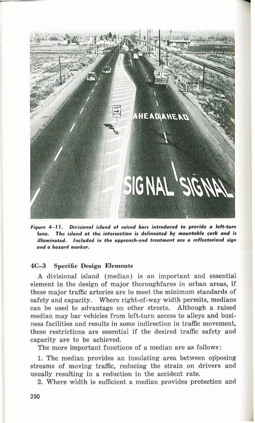
Figure 4-1 1 . Divisional island of raised bars introduced t o provide a left-turn lane. The island at the intersection is delineated by mountable curb and is illuminated, Included in the approach-end treatment are a reflectorized sign and a hazard marker.
PC-3 Specific Design Elements
A divisional island (median) is an important and essential element in the design of major thoroughfares in urban a r e a , if these major traffic arteries are to meet the minimum standards of safety and capacity. Where right-of-way width permits, medians can be used to advantage on other streets. Although a raised median may bar vehicles from left-turn access to alleys and busi- ness facilities and results in some indirection in traffic movement, these restrictions are essential if the desired traffic safety and capacity are to be achieved.
The more important functions iof a median are as follows:
1. The median provides an insulating area between osposing streams of moving traffic, reducing the strain on drivers and usually resulting in a reduction in the accident rate.
2. Where width is sufficient a median provides protection and

control of cross and turning traffic. One of the most important benefits of a median is obtained when a median or left-turn storage lane is provided. Left-kurning vehicles are separated in a protected lane so as not to impede the f l o w ~ f the through traffic, thus greatly increasing the efficiency, capacity, and safety of the intersection.
3. A median provides a refuge for pedestrians and decreases the need for installation of traffic signals. It makes possible more efficient signing and signalization in that traffic movements are regulated into orderly channels.
4. A median makes i t possible for traffic to move smoothly and safely a t higher operating speeds.
Where possible, the width of the divisional island should be sufficient to provide protection for vehicles crossing or turning a t intersections. Chapter VIII of A Policy on Geometric Design of Ilu?.al Highways, 1954, and Chapter D of A Policy on A ~ t e r i a l Highways in Urban Areas, 1957,29 should be consulted for an analysis of minimum designs for these conditions. Widths of 20 feet or more are desirable. Although narrow medians do pro-
Figure 4-12. Expressway with a painted-line median and frontage roads. The divisional island or outer separator is sodded and planted, and outlined by vertical curb.
a8Available from the American Association of State Highway Officials, 917 National Press Building, Washington 4, D.C.
251

vide some separation of opposing traffic and may serve for pedestrian refuge, medians less than 12 feet in width will not accommodate a median left-turn lane and a t cross-street openings provide only p e t i a l protection for turning and crossing traffic.
The minimum desirable width of a median which will accom- modate a median lane is 16 feet. Where right-of-way is severely limited, median widths of 12 feet have been used with a 10-foot turning lane. Whenever the separator of median lane and op- posing through traffic is narrower than 4 feet, i t should be com- posed of a mountable separator, mushroom buttons, or lane markings. Where the separator is 4 feet or wider either mount- able or barrier curbs should be used, with the type determined by local conditions (figs. 4-13 to 4-15, and 4-17). For further information on median lane design, the design policies of the American Association of State Highway Officials should be con- sulted.
FJgure 4-13. Median lane with mountable cancrefe curb traffic separcrtors having a scored face fw light reflection. Pavement markings and a hoxard mvrker give advance warning of the intfDdured separator.
Divisional islands should be delineated as discussed in section 4A-3. Vertical curbs are required on medians where i t is necessary to prohibit improper turning across the median area. On wide streets with heavy traffic volumes, curbed medians a t least 4 feet wide are needed for pedestrian protection, as discussed in section 4B-3. Other narrow medians should be mountable and

Figure 4-14. Separate left-turn lanes are notched into a relatively wide earth- filled median outlined with vertical curbs. The median lane separator is paved with concrete to serve as a pedestrian island.
may consist of low rolled curb sections with pavement filler, pave- ment markings, or a series of raised bars, corrugations, or but- tons placed along the centerline. Flush medians of contrasting pavement color are also used. On streets where snow removal is frequent, low rounded or flush median sections are preferable (figs. 4-12, 4-16, and 4-17).
Approach-end treatment should be as described in section 4A-4. A divisional island should not be located so as to begin on a sharp curve or a t the top of or just over a hillcrest where its presence in the roadway would introduce a surprise element to drivers.
Generally, divisional islands should not be placed where they will confine any part of the through roadway on either side to less than than two through traffic lanes, except when an island is used to separate through traffic from a left-turning median lane. Under extraordinary circumstancea it may be advantageous to provide a divisional island with only a single through traffic lane alongside. The width of a through lane will be governed by the volume, type, and speed of traffic and other local conditions and may vary from 10 to 13 feet.
At some locations where indiscriminate pedestrian crossings would be hazardous on streets with fairly high vehicle speeds or where sizable pedestrian volumes in certain hours would disrupt traffic flow, i t is advisable to consider erection of a pedestrian

barrier fence down the center of the divisional island. For clear- ance and maintenance, medians should be about 8 feet or more in width for such installations. The pedestrian barrier usually consists of some form of woven wire or picket fence and should be a t least 3 feet high. It should extend the entire length be- tween intersections, or for a distance of several hundred feet on either side beyond the point of pedestrian conflict. Such a-pedes- trian fence materially increases the visibility of the divisional island to the motorist and makes i t a more Gffective traffic separator.

Figure 4-16. Low divisional island that can be crossed by vehicles but which diseouruges mid-block left turns.
4C-4 Illumination and Reflectorization
Divisional islands and the proper lanes of travel along them should preferably be made clearly visible at night through the use of adequate and well directed street lighting. If lighting facilities are not available,. the island should be outlined as clearly as possible by the use of high-visibility approach-end devices as discussed in section 4A-4.
4C-5 Signs
A divisional islancl in the line of t raac flow shall be protectecl at the appl+oach encl by an appropriate reflectorized or illuminatecl ?ign or marker. An islaiicl with a width of 3 or more feet shall he protecterl with a regulatory Keep Right or a Doulllle Arrow warning sign (sees. iB-25, lC-34). On islands narrower than 3 feet a reflectorized hazard marker (sec. 2D-2) shall he used. Such signs or markers should be set back from the island ap- proach end to reduce the likelihood of being struck by a vehicle.
A continuous divisional island, except where very narrow or where defined by an unmountable curb, may also be protected by Keep Off Median signs (sec. 1B-37).
4C-6 Markings
The approach end of a divisional island in the line of traffic flow should be designed, signed, and marked to indicate its

Figure 4-17, Continuous median designated by pcrvement markings, providing median lanes a t every intersection.
presence and also to outline the proper vehicle paths. Where necessary the approaches to such an ielancl ehall he marked in ,
the manner provicled for refuge islands (secs. 4E-6, 2B-17 and
D.-CHANNELIZING ISLANDS
Section 4D-1 Legal Authority 1 Channelizing islands are elements of street and highway 1
design, and accordingly no special authority is required for their installation.
4D-2 Functions
The primary function of a channelizing island is to control and direct a motorist into the proper channel for his intended route and thus assure safe and efficient operation of the intersection. Channelizing islands are installed in areas that otherwise would

i be broad expanses of pavement, to bring about the desired orderly : flow of traffic. As such the channelizing island primarily is a ' part of intersection layout design, the details of which are covered
only in a general manner in this Manual.
4D-3 Specific Design Elements
The design of a channelized intersection can be decided only after special study of the particular area, i t being a part of the whole intersection layout. The shape and size of the islahds will vary widely according to the intersection tonditions. For chan- nelization of existing intersections i t is desirable to test the layout by temporarily delineatiilg the island area thro~lgh the use of sandbags, stanchions, or markings before final construction. Reference should be made to chapter VII of the Policy o n Geo- rnet7.i~ Design o f R L L ? . ~ ~ Highzoays "'' for design information. The number of channelizing islands used a t any intersection should be kept to a minimum. The entire layout should be the simplest design that will accomplish the desired intersection control. Usually a few carefully placed islands of above-minimum size are more effective than a greater number of small islands which create multiple channels and cause confusion (figs. 4-18. 4-19).
Figure 4-18. Channelized intersection of t w o major streets. The islands are
paved within the crosswalk lines.
80 Available from the Ameriean Association of State Highway Officials, 917 National Press Building, Washington 4, D.C.

Figure 4-19. Channelizing islands at an intersection. The islands are concrete platforms outlined by curb and gutter. The width of the divisional islands is reduced to provide left-turn lanes at the intersection.
The general design elements discussed in section 4A-3 are applicable in determining the appropriate method for designation of a channelizing island. Curbed islands are most often used in urban areas, but pavement markings, raised bars, mishroom buttons, or other designation methods are often appropriate where encroachment on the island is not dangerous to motorists, pedes- trians, or property (figs. 4-20, 4-21).

Figure 4-20. Channelized intersection with grass-covered islands outlined by high-visibility concrete curb and gutter. The design is supplemented by signalizafion, signs, pavement markings, and illumination.
rlgure 4-rr. bnwnnr,rzuri~n is accomplished through use of both concrete
and painted islands in this intersection. The entire area is well illuminated.
Channelizing islands should be constructed with a color a._- texture of surface area contrasting with that of the adjacent pavement, and should be designed and located so that the proper travel paths are obvious, easy to follow, and unquestionably con- f tinuous (figs. 4-22, 4-23). Approach-end treatment should be j as discussed in section 4A-4.
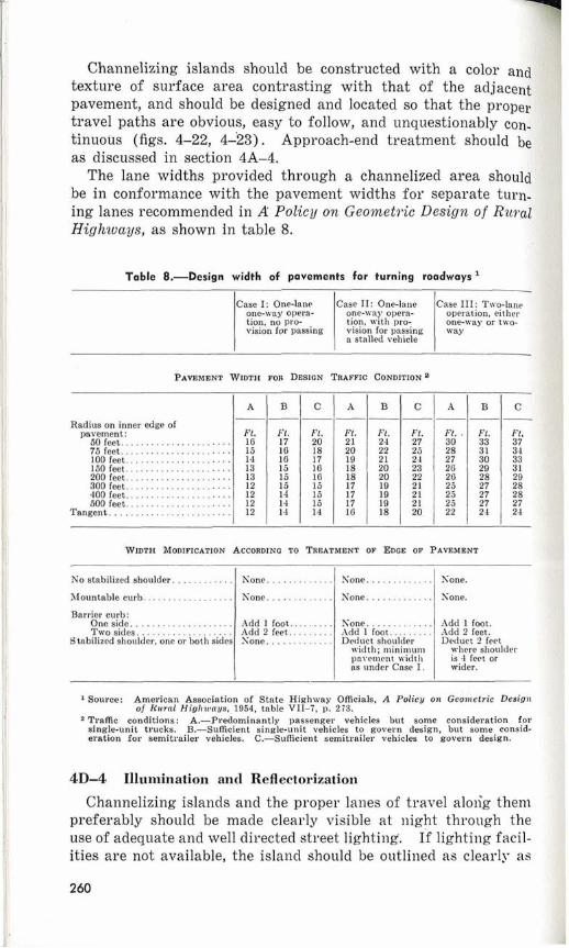
The lane widths provided through a channelized area should : be in conformance with the pavement widths for separate turn- ing lanes recommended in A Policy on G e o m e t ~ i c Design o f Ru?.al La Highzuays, as shown in table 8.
Table 8.-Design width of pavements for turning roadways l
a stalled vehicle
PAVEMENT WIDTH FOR DESIGN TRAFFIC CONDITION 8
A B C A B C A B C - - - - - - - - -
Radius on inner edge of pavement: Ft. Ft . F1. Ft . Ft. Ft. F t . . Ft. Fl.
50feet . . . . . . . . . . . . . . . . . . . . . . 16 17 20 21 24 27 30 33 37 75 feet. . . . . . . . . . . . . . . . . . . . . . 15 1G 18 20 22 25 28 31 34 100feet . . . . . . . . . . . . . . . . . . . . . 14 1G 17 19 21 24 27 30 33 150 feet.. . . . . . . . . . . . . . . . . . . . 13 15 16 18 20 23 26 29 31 200 feet. . . . . . . . . . . . . . . . . . . . . 13 15 16 18 20 22 26 28 29 300feet . . . . . . . . . . . . . . . . . . . . . 12 15 15 17 19 21 25 27 28 400feet . . . . . . . . . . . . . . . . . . . . . 12 14 15 17 19 21 25 27 28 500feet . . . . . . . . . . . . . . . . . . . . . 12 14 15 17 19 21 25 27 27
Tangent . . . . . . . . . . . . . . . . . . . . . . . . 12 14 14 1 G 18 20 22 24 24
WIDTH MODIFICATION ACCORDING TO TREATMENT OF EDGE OF PAVEMENT
No stabilized ahoulder . . . . . . . . . . . . None. . . . . . . . . . . . . Xone. . . . . . . . . . . . . Xone.
Mountable curb.. . . . . . . . . . . . . . . . . None. . . . . . . . . . . . . None. . . . . . . . . . . . . Xone.
Barrier curb: One side. . . . . . . . . . . . . . . . . . . . Two sides. . . . . . . . . . . . . . . . . . .
Stabilized shoulder, one or both sides
Add 1 foot.. . . Add 2 feet.. . . Xone . . . . . . . .
Kone . . . . . . . . . . . . . Add 1 foot. . . . . . . . . Deduct shoulder
width; minimum pavement ~ v i d t l ~ as under Case I .
.4dd 1 foot. Add 2 feet. Deduct 2 feet
where sl~oulder is 4 feet or wider.
1 Source: Amevican Association of State Highway Officials, A Policy on Geon~etric Design of Rural Higl~zoaus. 1954. table VII-I, p. 273.
'Traffic conditions: A.-Predominantly passenger vehicles but some consideration for single-unit trucks. B.-Sufficient single-unit vehicles to govern design, but some consid- eration for semitrailer vehicles. C.-Sufficient semitrailer vehicles to govern design.
4 D 4 Illuiiiination and Reflectorization
Channelizing islands and the proper lanes of travel alolig them preferably should be made clearly visible a t night through the j use of adequate and well directed street lighting. If lighting facil- , ities are not available, the island should be outlined as clearly as ,f
4
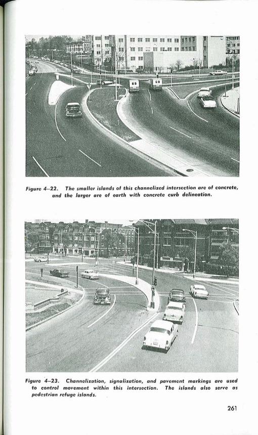
Figure 4-22. The smaller islands of this channelized intersection are of concrete, m d the larger are of earth with concrete curb delineation.
Figure 4-23. Channelization, signalization, and pavement markings are used to control movement within this intersection. The islands also serve as pedestrian refuge islands.

possible by the use of high-visibility approach-end devices (Bec. 4A-4).
4D-5 Signs
Channelizing islands i i the lines of traffic streams shall be pro. tected at the approach ends by appropriate reflectorized or illuminatec1 signs. As conditions require, a regulatory Keep Right sign (sec. 1B-26) or other appropriate signs should be used.
4D-6 Markings
The approach end of channelizing islands in the main streams of traffic flow sho~lld be marked to indicate their presence and also to outline the proper vehicle paths. The methods used are discussed in section 4B-6. Markings may not be necessary at , secondary islands located within a multiple-island intersection. All markings should be in accordance with sections 2B-15, 17 and 18, and 2C-4.