part 2. signs chapter 2e. guide signs - freeways and ...chapter 2e. guide signs - freeways and...
TRANSCRIPT
December, 2011
PART 2. SIGNSChapter 2E. Guide Signs - Freeways and Expressways
TABLE OF CONTENTS
Chapter 2E. Guide Signs - Freeways and Expressways PageSection 2E.1 Scope of Freeway and Expressway Guide Sign Standards. . . . . . . . . . . . . . . . . . . . . . . . 2E-1
2E.2 Freeway and Expressway Signing Principles . . . . . . . . . . . . . . . . . . . . . . . . . . . . . . . . . . 2E-12E.3 Guide Sign Classification . . . . . . . . . . . . . . . . . . . . . . . . . . . . . . . . . . . . . . . . . . . . . . . . . 2E-12E.4 General. . . . . . . . . . . . . . . . . . . . . . . . . . . . . . . . . . . . . . . . . . . . . . . . . . . . . . . . . . . . . . . . 2E-22E.5 Color of Guide Signs. . . . . . . . . . . . . . . . . . . . . . . . . . . . . . . . . . . . . . . . . . . . . . . . . . . . . 2E-22E.6 Retroreflection or Illumination . . . . . . . . . . . . . . . . . . . . . . . . . . . . . . . . . . . . . . . . . . . . . 2E-22E.7 Characteristics of Urban Signing . . . . . . . . . . . . . . . . . . . . . . . . . . . . . . . . . . . . . . . . . . . 2E-22E.8 Characteristics of Rural Signing . . . . . . . . . . . . . . . . . . . . . . . . . . . . . . . . . . . . . . . . . . . . 2E-22E.9 Signing of Named Highways . . . . . . . . . . . . . . . . . . . . . . . . . . . . . . . . . . . . . . . . . . . . . . 2E-32E.10 Amount of Legend on Guide Signs. . . . . . . . . . . . . . . . . . . . . . . . . . . . . . . . . . . . . . . . . . 2E-32E.11 Number of Signs at an Overhead Installation and Sign Spreading . . . . . . . . . . . . . . . . . 2E-32E.12 Pull-Through Signs . . . . . . . . . . . . . . . . . . . . . . . . . . . . . . . . . . . . . . . . . . . . . . . . . . . . . . 2E-32E.13 Designation of Destinations . . . . . . . . . . . . . . . . . . . . . . . . . . . . . . . . . . . . . . . . . . . . . . . 2E-52E.14 Size and Style of Letters and Signs. . . . . . . . . . . . . . . . . . . . . . . . . . . . . . . . . . . . . . . . . . 2E-52E.15 Interline and Edge Spacing . . . . . . . . . . . . . . . . . . . . . . . . . . . . . . . . . . . . . . . . . . . . . . . . 2E-122E.16 Sign Borders . . . . . . . . . . . . . . . . . . . . . . . . . . . . . . . . . . . . . . . . . . . . . . . . . . . . . . . . . . . 2E-122E.17 Abbreviations. . . . . . . . . . . . . . . . . . . . . . . . . . . . . . . . . . . . . . . . . . . . . . . . . . . . . . . . . . . 2E-122E.18 Symbols . . . . . . . . . . . . . . . . . . . . . . . . . . . . . . . . . . . . . . . . . . . . . . . . . . . . . . . . . . . . . . . 2E-122E.19 Arrows for Interchange Guide Signs. . . . . . . . . . . . . . . . . . . . . . . . . . . . . . . . . . . . . . . . . 2E-132E.20 Signing for Option Lanes at Splits and Multi-Lane Exits . . . . . . . . . . . . . . . . . . . . . . . . 2E-142E.21 Design of Overhead Arrow-per-Lane Guide Signs for Option Lanes . . . . . . . . . . . . . . . 2E-142E.22 Design of Freeway and Expressway Guide Signs for Option Lanes . . . . . . . . . . . . . . . . 2E-192E.23 Signing for Intermediate and Minor Interchange Multi-Lane Exits
with an Option Lane . . . . . . . . . . . . . . . . . . . . . . . . . . . . . . . . . . . . . . . . . . . . . . . . 2E-232E.24 Signing for Interchange Lane Drops . . . . . . . . . . . . . . . . . . . . . . . . . . . . . . . . . . . . . . . . . 2E-262E.25 Overhead Sign Installations. . . . . . . . . . . . . . . . . . . . . . . . . . . . . . . . . . . . . . . . . . . . . . . . 2E-262E.26 Lateral Offset . . . . . . . . . . . . . . . . . . . . . . . . . . . . . . . . . . . . . . . . . . . . . . . . . . . . . . . . . . . 2E-272E.27 Route Signs and Trailblazer Assemblies . . . . . . . . . . . . . . . . . . . . . . . . . . . . . . . . . . . . . . 2E-312E.28 Eisenhower Interstate System Signs (M1-10, M1-10a) . . . . . . . . . . . . . . . . . . . . . . . . . . 2E-322E.29 Signs for Intersections at Grade . . . . . . . . . . . . . . . . . . . . . . . . . . . . . . . . . . . . . . . . . . . . 2E-322E.30 Interchange Guide Signs . . . . . . . . . . . . . . . . . . . . . . . . . . . . . . . . . . . . . . . . . . . . . . . . . . 2E-322E.31 Interchange Exit Numbering . . . . . . . . . . . . . . . . . . . . . . . . . . . . . . . . . . . . . . . . . . . . . . . 2E-322E.32 Interchange Classification . . . . . . . . . . . . . . . . . . . . . . . . . . . . . . . . . . . . . . . . . . . . . . . . . 2E-332E.33 Advance Guide Signs . . . . . . . . . . . . . . . . . . . . . . . . . . . . . . . . . . . . . . . . . . . . . . . . . . . . 2E-372E.34 Next Exit Plaques . . . . . . . . . . . . . . . . . . . . . . . . . . . . . . . . . . . . . . . . . . . . . . . . . . . . . . . 2E-382E.35 Other Supplemental Guide Signs . . . . . . . . . . . . . . . . . . . . . . . . . . . . . . . . . . . . . . . . . . . 2E-392E.36 Exit Direction Signs . . . . . . . . . . . . . . . . . . . . . . . . . . . . . . . . . . . . . . . . . . . . . . . . . . . . . 2E-402E.37 Exit Gore Signs (E5-1 Series) . . . . . . . . . . . . . . . . . . . . . . . . . . . . . . . . . . . . . . . . . . . . . . 2E-422E.38 Post-Interchange Signs . . . . . . . . . . . . . . . . . . . . . . . . . . . . . . . . . . . . . . . . . . . . . . . . . . . 2E-432E.39 Post-Interchange Distance Signs . . . . . . . . . . . . . . . . . . . . . . . . . . . . . . . . . . . . . . . . . . . . 2E-432E.40 Interchange Sequence Signs . . . . . . . . . . . . . . . . . . . . . . . . . . . . . . . . . . . . . . . . . . . . . . . 2E-452E.41 Community Interchanges Identification Signs . . . . . . . . . . . . . . . . . . . . . . . . . . . . . . . . . 2E-45
2E-i
2E-iiDecember, 2011
Page2E.42 NEXT XX EXITS Sign. . . . . . . . . . . . . . . . . . . . . . . . . . . . . . . . . . . . . . . . . . . . . . . . . . . 2E-462E.43 Signing by Type of Interchange . . . . . . . . . . . . . . . . . . . . . . . . . . . . . . . . . . . . . . . . . . . . 2E-462E.44 Freeway-to-Freeway Interchange . . . . . . . . . . . . . . . . . . . . . . . . . . . . . . . . . . . . . . . . . . . 2E-462E.45 Cloverleaf Interchange . . . . . . . . . . . . . . . . . . . . . . . . . . . . . . . . . . . . . . . . . . . . . . . . . . . 2E-492E.46 Cloverleaf Interchange with Collector-Distributor Roadways . . . . . . . . . . . . . . . . . . . . . 2E-492E.47 Partial Cloverleaf Interchange. . . . . . . . . . . . . . . . . . . . . . . . . . . . . . . . . . . . . . . . . . . . . . 2E-492E.48 Diamond Interchange . . . . . . . . . . . . . . . . . . . . . . . . . . . . . . . . . . . . . . . . . . . . . . . . . . . . 2E-532E.49 Diamond Interchange in Urban Area . . . . . . . . . . . . . . . . . . . . . . . . . . . . . . . . . . . . . . . . 2E-532E.50 Closely Spaced Interchanges. . . . . . . . . . . . . . . . . . . . . . . . . . . . . . . . . . . . . . . . . . . . . . . 2E-532E.51 Minor Interchange . . . . . . . . . . . . . . . . . . . . . . . . . . . . . . . . . . . . . . . . . . . . . . . . . . . . . . . 2E-532E.52 Signing on Conventional Road Approaches and Connecting Roadways . . . . . . . . . . . . . 2E-572E.53 Wrong-Way Traffic Control at Interchange Ramps . . . . . . . . . . . . . . . . . . . . . . . . . . . . . 2E-572E.54 Weigh Station Signing . . . . . . . . . . . . . . . . . . . . . . . . . . . . . . . . . . . . . . . . . . . . . . . . . . . . 2E-57
FIGURESFigure 2E-1 Example of Guide Sign Spreading . . . . . . . . . . . . . . . . . . . . . . . . . . . . . . . . . . . . . . . . . . 2E-4Figure 2E-2 Pull-Through Signs . . . . . . . . . . . . . . . . . . . . . . . . . . . . . . . . . . . . . . . . . . . . . . . . . . . . . . 2E-4Figure 2E-3 Overhead Arrow-per-Lane Guide Sign for a Multi-Lane Exit with an Option Lane . . . . 2E-13Figure 2E-4 Overhead Arrow-per-Lane Guide Signs for a Two-Lane Exit
to the Right with an Option Lane . . . . . . . . . . . . . . . . . . . . . . . . . . . . . . . . . . . . . . . . . . . 2E-16Figure 2E-5 Overhead Arrow-per-Lane Guide Signs for a Two-Lane Exit to the Right
with an Option Lane (Through Lanes Curve to the Left) . . . . . . . . . . . . . . . . . . . . . . . . . 2E-17Figure 2E-6 Overhead Arrow-per-Lane Guide Signs for a Split with an Option Lane . . . . . . . . . . . . 2E-18Figure 2E-7 Diagrammatic Guide Sign for Multi-Lane Exit with an Option Lane . . . . . . . . . . . . . . . 2E-19Figure 2E-8 Diagrammatic Guide Signs for a Two-Lane Exit to the Right with an Optional Lane . . 2E-20Figure 2E-9 Diagrammatic Guide Signs for a Two-Lane Exit to the Right
with an Optional Lane (Through Lanes Curve to the Left) . . . . . . . . . . . . . . . . . . . . . . . 2E-21Figure 2E-10 Diagrammatic Guide Signs for a Split with an Optional Lane. . . . . . . . . . . . . . . . . . . . . 2E-22Figure 2E-11 Example of Signing for a Two-Lane Intermediate or Minor Interchange Exit
with an Option Lane and a Dropped Lane . . . . . . . . . . . . . . . . . . . . . . . . . . . . . . . . . . . . 2E-24 Figure 2E-12 Example of Signing for a Two-Lane Intermediate or Minor Interchange Exit
with an Option and Auxiliary Lanes . . . . . . . . . . . . . . . . . . . . . . . . . . . . . . . . . . . . . . . . . 2E-25 Figure 2E-13 EXIT ONLY and LEFT Panels . . . . . . . . . . . . . . . . . . . . . . . . . . . . . . . . . . . . . . . . . . . . . 2E-27Figure 2E-14 Guide Signs for a Split with Dedicated Lanes . . . . . . . . . . . . . . . . . . . . . . . . . . . . . . . . . 2E-28Figure 2E-15 Guide Signs for a Single-Lane Exit to the Left with a Dropped Lane . . . . . . . . . . . . . . . 2E-29Figure 2E-16 Guide Signs for a Single-Lane Exit to the Right with a Dropped Lane . . . . . . . . . . . . . . 2E-30Figure 2E-17 This figure has been eliminatedFigure 2E-18 This figure has been eliminatedFigure 2E-19 Example of Interchange Numbering for Mainline and Circumferential Routes . . . . . . . 2E-34Figure 2E-20 Example of Interchange Numbering for Mainline, Loop, and Spur Routes. . . . . . . . . . . 2E-35Figure 2E-21 Example of Interchange Numbering for Overlapping Routes . . . . . . . . . . . . . . . . . . . . . 2E-36Figure 2E-22 Examples of Interchange Advance Guide Signs,
Exit Number Plaques, and LEFT Plaques . . . . . . . . . . . . . . . . . . . . . . . . . . . . . . . . . . . . 2E-37Figure 2E-23 Next Exit Plaques . . . . . . . . . . . . . . . . . . . . . . . . . . . . . . . . . . . . . . . . . . . . . . . . . . . . . . . 2E-38Figure 2E-24 Supplemental Guide Signs for a Multi-Exit Interchange . . . . . . . . . . . . . . . . . . . . . . . . . 2E-39Figure 2E-25 Supplemental Guide Sign for a Park - Ride Facility . . . . . . . . . . . . . . . . . . . . . . . . . . . . 2E-39
July, 2013
Page
Figure 2E-26 Examples of Interchange Exit Direction Signs . . . . . . . . . . . . . . . . . . . . . . . . . . . . . . . . . 2E-40Figure 2E-27 Interchange Exit Direction Sign with an Advisory Speed Panel . . . . . . . . . . . . . . . . . . . 2E-41Figure 2E-28 Exit Gore Signs . . . . . . . . . . . . . . . . . . . . . . . . . . . . . . . . . . . . . . . . . . . . . . . . . . . . . . . . . 2E-42Figure 2E-29 Post-Interchange Distance Sign. . . . . . . . . . . . . . . . . . . . . . . . . . . . . . . . . . . . . . . . . . . . . 2E-43Figure 2E-30 Example of Using an Interchange Sequence Sign for Closely Spaced Interchanges . . . . 2E-44Figure 2E-31 Interchange Sequence Sign . . . . . . . . . . . . . . . . . . . . . . . . . . . . . . . . . . . . . . . . . . . . . . . . 2E-45Figure 2E-32 Community Interchanges Identification Sign . . . . . . . . . . . . . . . . . . . . . . . . . . . . . . . . . . 2E-45Figure 2E-33 NEXT EXITS Sign . . . . . . . . . . . . . . . . . . . . . . . . . . . . . . . . . . . . . . . . . . . . . . . . . . . . . . 2E-46Figure 2E-34 Examples of Guide Signs for a Freeway-to-Freeway Interchange (Sheet 1 of 2) . . . . . . 2E-47Figure 2E-34 Examples of Guide Signs for a Freeway-to-Freeway Interchange (Sheet 2 of 2) . . . . . . 2E-48Figure 2E-35 Examples of Guide Signs for a Full Cloverleaf Interchange . . . . . . . . . . . . . . . . . . . . . . 2E-50Figure 2E-36 Examples of Guide Signs for a Full Cloverleaf Interchange
with Collector-Distributor Roadways . . . . . . . . . . . . . . . . . . . . . . . . . . . . . . . . . . . 2E-51Figure 2E-37 Examples of Guide Signs for a Partial Cloverleaf Interchange . . . . . . . . . . . . . . . . . . . . 2E-52Figure 2E-38 Examples of Guide Signs for a Diamond Interchange . . . . . . . . . . . . . . . . . . . . . . . . . . . 2E-54Figure 2E-39 Examples of Guide Signs for a Diamond Interchange in an Urban Area. . . . . . . . . . . . . 2E-55Figure 2E-40 Examples of Guide Signs for a Minor Interchange . . . . . . . . . . . . . . . . . . . . . . . . . . . . . 2E-56
TABLESTable 2E-1 Freeway or Expressway Guide Sign and Plaque Sizes (Sheet 1 of 2) . . . . . . . . . . . . . . . 2E-6Table 2E-1 Freeway or Expressway Guide Sign and Plaque Sizes (Sheet 2 of 2) . . . . . . . . . . . . . . . 2E-7Table 2E-2 Minimum Letter and Numeral Sizes for Expressway Guide Signs
According to Interchange Classification . . . . . . . . . . . . . . . . . . . . . . . . . . . . . . . . . 2E-8Table 2E-3 Minimum Letter and Numeral Sizes for Expressway Guide Signs
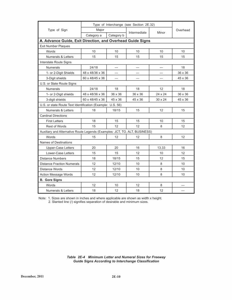
According to Sign Type. . . . . . . . . . . . . . . . . . . . . . . . . . . . . . . . . . . . . . . . . . . . . . 2E-9Table 2E-4 Minimum Letter and Numeral Sizes for Freeway Guide Signs
According to Interchange Classification . . . . . . . . . . . . . . . . . . . . . . . . . . . . . . . . . 2E-10Table 2E-5 Minimum Letter and Numeral Sizes for Freeway Guide Signs
According to Sign Type. . . . . . . . . . . . . . . . . . . . . . . . . . . . . . . . . . . . . . . . . . . . . . 2E-11
2E-iii
December, 20112E-1
PART 2. SIGNSChapter 2E. Guide Signs - Freeways and Expressways
2E.1 Scope of Freeway and ExpresswayGuide Sign Standards
The provisions of this Chapter provide a uniform andeffective system of signing for high-volume, high-speedmotor vehicle traffic on freeways and expressways. Therequirements and specifications for expressway signingexceed those for conventional roads (see Chapter 2D), butare less than those for freeway signing. Since there are manygeometric design variables to be found in existing roads, asigning concept commensurate with prevailing conditions isthe primary consideration. Section 1A.13 includesdefinitions of freeway and expressway.
Guide signs for freeways and expressways are primarilyidentified by the name of the sign rather than by an assignedsign designation. Guidelines for the design of guide signs forfreeways and expressways are provided in the "StandardHighway Signs and Markings" book (see Section 1A.11).
The provisions of this Chapter shall apply to any highwaythat meets the definition of freeway or expressway facilities.
2E.2 Freeway and ExpresswaySigning Principles
The development of a signing system for freeways andexpressways is approached on the premise that the signing isprimarily for the benefit and direction of road users who arenot familiar with the route or area. The signing furnishesroad users with clear instructions for orderly progress totheir destinations. Sign installations are an integral part ofthe facility and, as such, are best planned concurrently withthe development of highway location and geometric design.For optimal results, plans for signing are analyzed during theearliest stages of preliminary design, and details arecorrelated as final design is developed. The excessivesigning found on many major highways usually is the resultof using a multitude of signs that are too small and that arepoorly designed and placed to accomplish the intendedpurpose.
Freeway and expressway signing is to be considered anddeveloped as a planned system of installations. Anengineering study is sometimes necessary for proper
STANDARD:STANDARD:
SUPPORT:SUPPORT:
SUPPORT:SUPPORT:
solution of the problems of many individual locations, but,in addition, consideration of an entire route is necessary.
Road users should be guided with consistent signing onthe approaches to interchanges, when they drive from oneState to another, and when driving through rural or urbanareas. Because geographical, geometric, and operatingfactors regularly create significant differences betweenurban and rural conditions, the signing should take theseconditions into account.
Guide signs on freeways and expressways should servedistinct functions as follows:
A. Give directions to destinations, or to streets orhighway routes, at intersections or interchanges;
B. Furnish advance notice of the approach to intersec-tions or interchanges;
C. Direct road users into appropriate lanes in advance ofdiverging or merging movements;
D. Identify routes and directions on those routes;E. Show distances to destinations;F. Indicate access to general motorist services, rest,
scenic, and recreational areas; andG. Provide other information of value to the road user.
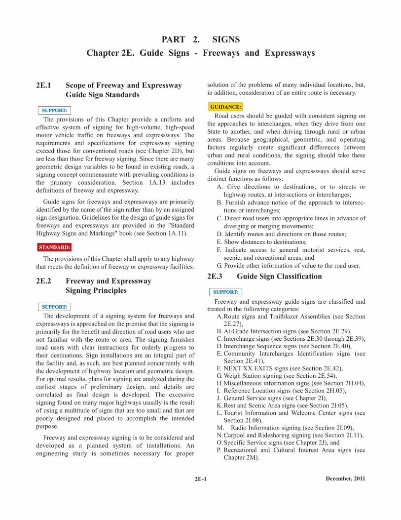
2E.3 Guide Sign Classification
Freeway and expressway guide signs are classified andtreated in the following categories:
A.Route signs and Trailblazer Assemblies (see Section2E.27),
B. At-Grade Intersection signs (see Section 2E.29), C. Interchange signs (see Sections 2E.30 through 2E.39), D.Interchange Sequence signs (see Section 2E.40), E. Community Interchanges Identification signs (see
Section 2E.41), F. NEXT XX EXITS signs (see Section 2E.42), G. Weigh Station signing (see Section 2E.54), H.Miscellaneous information signs (see Section 2H.04), I. Reference Location signs (see Section 2H.05), J. General Service signs (see Chapter 2I), K.Rest and Scenic Area signs (see Section 2I.05), L. Tourist Information and Welcome Center signs (see
Section 2I.08), M. Radio Information signing (see Section 2I.09), N.Carpool and Ridesharing signing (see Section 2I.11), O.Specific Service signs (see Chapter 2J), and P. Recreational and Cultural Interest Area signs (see
Chapter 2M).
SUPPORT:SUPPORT:
GUIDANCE:GUIDANCE:
2E.4 General
Signs are designed so that they are legible to road usersapproaching them and readable in time to permit properresponses. Desired design characteristics include: (a) longvisibility distances, (b) large lettering, symbols, and arrows,and (c) short legends for quick comprehension.
Standard shapes and colors shall be used so that trafficsigns can be promptly recognized by road users.
2E.5 Color of Guide Signs
Guide signs on freeways and expressways, except asotherwise provided in this Manual, shall have white lettersand numerals, symbols, arrows, and borders on a greenbackground.
Color requirements for route signs and trailblazers, signswith blank-out or changeable messages, signs for services,rest areas, park and recreational areas, and for certain mis-cellaneous signs are provided in the individual Sectionsdealing with the particular sign or sign group.
2E.6 Retroreflection or Illumination
Letters, numerals, symbols, arrows, and borders of allguide signs shall be retroreflectorized. The background of allguide signs that are not independently illuminated shall beretroreflective.
Where there is no serious interference from extraneouslight sources, retroreflectorized post-mounted signs usuallyprovide adequate nighttime visibility.
On freeways and expressways where much driving atnight is done with low-beam headlights, the amount ofheadlight illumination incident to an overhead sign displayis relatively small.
Overhead sign installations should be illuminated unlessan engineering study shows that retroreflectorization alonewill perform effectively. The type of illumination chosenshould provide effective and reasonably uniform illumina-tion of the sign face and message.
GUIDANCE:GUIDANCE:
STANDARD:STANDARD:
STANDARD:STANDARD:
SUPPORT:SUPPORT:
SUPPORT:SUPPORT:
SUPPORT:SUPPORT:
STANDARD:STANDARD:
2E.7 Characteristics of Urban Signing
Urban conditions are characterized not so much by citylimits or other arbitrary boundaries, as by the followingfeatures:
A. Mainline roadways with more than two lanes in eachdirection;
B. High traffic volumes on the through roadways;C. High volumes of traffic entering and leaving inter-
changes;D. Interchanges closely spaced;E. Roadway and interchange lighting;F. Three or more interchanges serving the major city;G. A loop, circumferential, or spur serving a sizable
portion of the urban population; andH. Visual clutter from roadside development.
Operating conditions and road geometrics on urbanfreeways and expressways usually make special signtreatments desirable, including:
A.Use of Interchange Sequence signs (see Section2E.40);
B. Use of sign spreading to the maximum extent possible(see Section 2E.11);
C. Elimination of General or Specific Service signing(see Chapters 2I and 2J);
D.Reduction to a minimum of post-interchange signs(see Section 2E.38);
E. Display of advance signs at distances closer to theinterchange, with appropriate adjustments in thelegend (see Section 2E.33);
F. Use of overhead signs on roadway structures andindependent sign supports (see Section 2E.25);
G. Use of Overhead Arrow-per-Lane or Diagrammaticguide signs in advance of intersections and inter-changes (see Sections 2E.21 and 2E.22); and
H.Frequent use of street names as the principal messagein guide signs.
.Lower speeds which are often characteristic of urbanoperations do not justify lower signing standards.Typical traffic patterns are more complex for the roaduser to negotiate, and large, easy-to-read legends are,therefore, just as necessary as on rural highways.
2E.8 Characteristics of Rural Signing
Rural areas ordinarily have greater distances betweeninterchanges, which permits adequate spacing for thesequences of signs on the approach to and departure fromeach interchange. However, the absence of traffic inadjoining lanes and on entering or exiting ramps often addsmonotony or inattention to rural driving. This increases theimportance of signs that call for decisions or actions.
SUPPORT:SUPPORT:
SUPPORT:SUPPORT:
2E-2December, 2011
Where there are long distances between interchanges andthe alignment is relatively unchanging, signs should bepositioned for their best effect on road users. The tendencyto group all signing in the immediate vicinity of rural inter-changes should be avoided by considering the entire route inthe development of sign plans. Extra effort should be givento the placement of signs at natural target locations tocommand the attention of the road user, particularly whenthe message requires an action by the road user.
2E.9 Signing of Named Highways
Section 2D.53 contains information, which is alsoapplicable to freeways and expressways, regarding the useof highway names on the signing for unnumbered highwaysto enhance route guidance and facilitate travel.
Section 2M.10 contains information regarding memorialsigning of routes, bridges, or highway components.
2E.10 Amount of Legend on Guide Signs
No more than two destination names or street namesshould be displayed on any Advance Guide sign or ExitDirection sign. A city name and street name on the same signshould be avoided. Where two or three signs are placed onthe same supports, destinations or names should be limitedto one per sign, or to a total of three in the display. Signlegends should not exceed three lines of copy, exclusive ofthe exit number and action or distance information.
2E.11 Number of Signs at an OverheadInstallation and Sign Spreading
If overhead signs are warranted, as set forth in Section2A.17, the number of signs at these locations should belimited to only those essential in communicating pertinentdestination information to the road user. Exit Direction signsfor a single exit and the Advance Guide signs should haveonly one sign with one or two destinations. Regulatorysigns, such as speed limits, should not be used inconjunction with overhead guide sign installations. Becauseroad users have limited time to read and comprehend signmessages, there should not be more than three guide signsdisplayed at any one location either on the overheadstructure or its support.
At overhead locations, more than one sign may beinstalled to advise of a multiple exit condition at an
OPTION:OPTION:
GUIDANCE:GUIDANCE:
GUIDANCE:GUIDANCE:
SUPPORT:SUPPORT:
GUIDANCE:GUIDANCE:interchange. If the roadway ramp or crossing roadway hascomplex or unusual geometrics, additional signs withconfirming messages may be provided to properly guide theroad user.
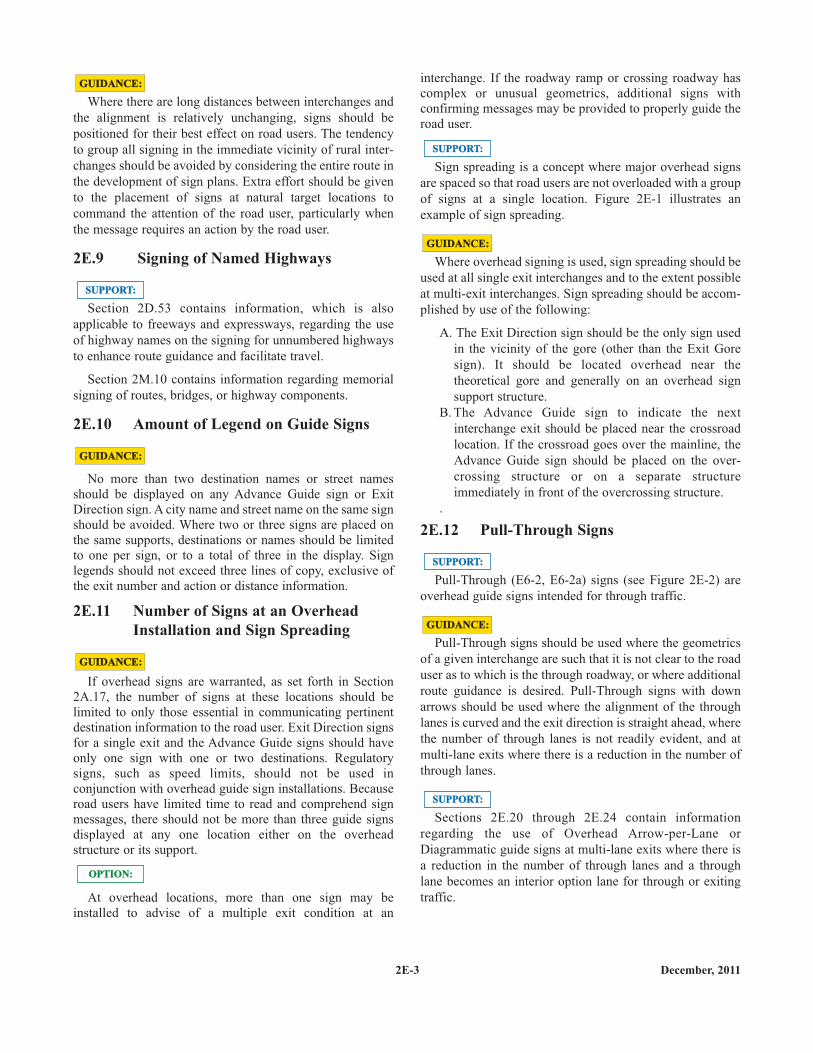
Sign spreading is a concept where major overhead signsare spaced so that road users are not overloaded with a groupof signs at a single location. Figure 2E-1 illustrates anexample of sign spreading.
Where overhead signing is used, sign spreading should beused at all single exit interchanges and to the extent possibleat multi-exit interchanges. Sign spreading should be accom-plished by use of the following:
A. The Exit Direction sign should be the only sign usedin the vicinity of the gore (other than the Exit Goresign). It should be located overhead near thetheoretical gore and generally on an overhead signsupport structure.
B. The Advance Guide sign to indicate the nextinterchange exit should be placed near the crossroadlocation. If the crossroad goes over the mainline, theAdvance Guide sign should be placed on the over-crossing structure or on a separate structureimmediately in front of the overcrossing structure.
.
2E.12 Pull-Through Signs
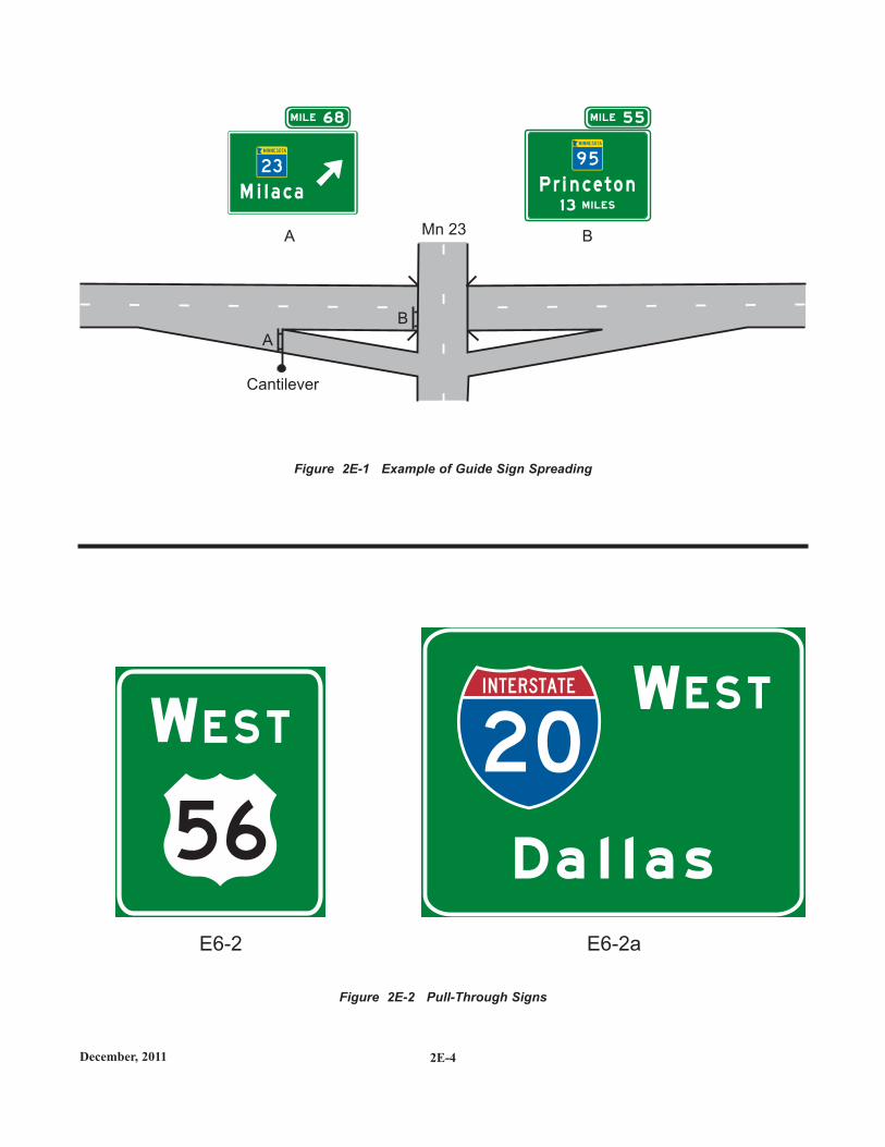
Pull-Through (E6-2, E6-2a) signs (see Figure 2E-2) areoverhead guide signs intended for through traffic.
Pull-Through signs should be used where the geometricsof a given interchange are such that it is not clear to the roaduser as to which is the through roadway, or where additionalroute guidance is desired. Pull-Through signs with downarrows should be used where the alignment of the throughlanes is curved and the exit direction is straight ahead, wherethe number of through lanes is not readily evident, and atmulti-lane exits where there is a reduction in the number ofthrough lanes.
Sections 2E.20 through 2E.24 contain informationregarding the use of Overhead Arrow-per-Lane orDiagrammatic guide signs at multi-lane exits where there isa reduction in the number of through lanes and a throughlane becomes an interior option lane for through or exitingtraffic.
SUPPORT:SUPPORT:
GUIDANCE:GUIDANCE:
SUPPORT:SUPPORT:
GUIDANCE:GUIDANCE:
SUPPORT:SUPPORT:
2E-3 December, 2011
December, 2011 2E-4
Figure 2E-2 Pull-Through Signs
Figure 2E-1 Example of Guide Sign Spreading
E6-2 E6-2a
WES TWES T
B
Mn 23
A
Cantilever
A B
68M I LE
M i l a c a
23
5 5M I LE
P r i n c e t o n1 3 M I LES
9 5
2E.13 Designation of Destinations
The direction of a freeway and the major destinations orcontrol cities along it shall be clearly identified through theuse of appropriate destination legends (see Section 2D.37).Successive freeway guide signs shall provide continuity indestination names and consistency with available mapinformation. At any decision point, a given destination shallbe indicated by way of only one route.
Control city legends should be used in the followingsituations along a freeway:
A. At interchanges between freeways;B. At separation points of overlapping freeway routes;C. On directional signs on intersecting routes, to guide
traffic entering the freeway;D. On Pull-Through signs; andE. On the bottom line of post-interchange distance signs.
Continuity of destination names is also useful onexpressways serving long-distance or intrastate travel.
The determination of major destinations or control citiesis important to the quality of service provided by thefreeway. Control cities on freeway guide signs are selectedby the States and are contained in the "Guidelines for theSelection of Supplemental Guide Signs for TrafficGenerators Adjacent to Freeways, 4th Edition/Guide Signs,Part II: Guidelines for Airport Guide Signing/Guide Signs,Part III: List of Control Cities for Use in Guide Signs onInterstate Highways," published by and available from theAmerican Association of State and Highway TransportationOfficials (see Section 1A.11).
2E.14 Size and Style of Letters and Signs
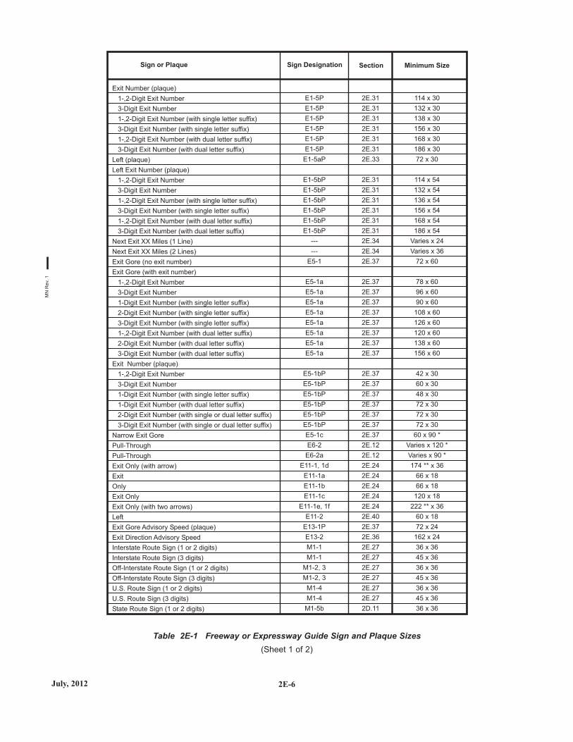
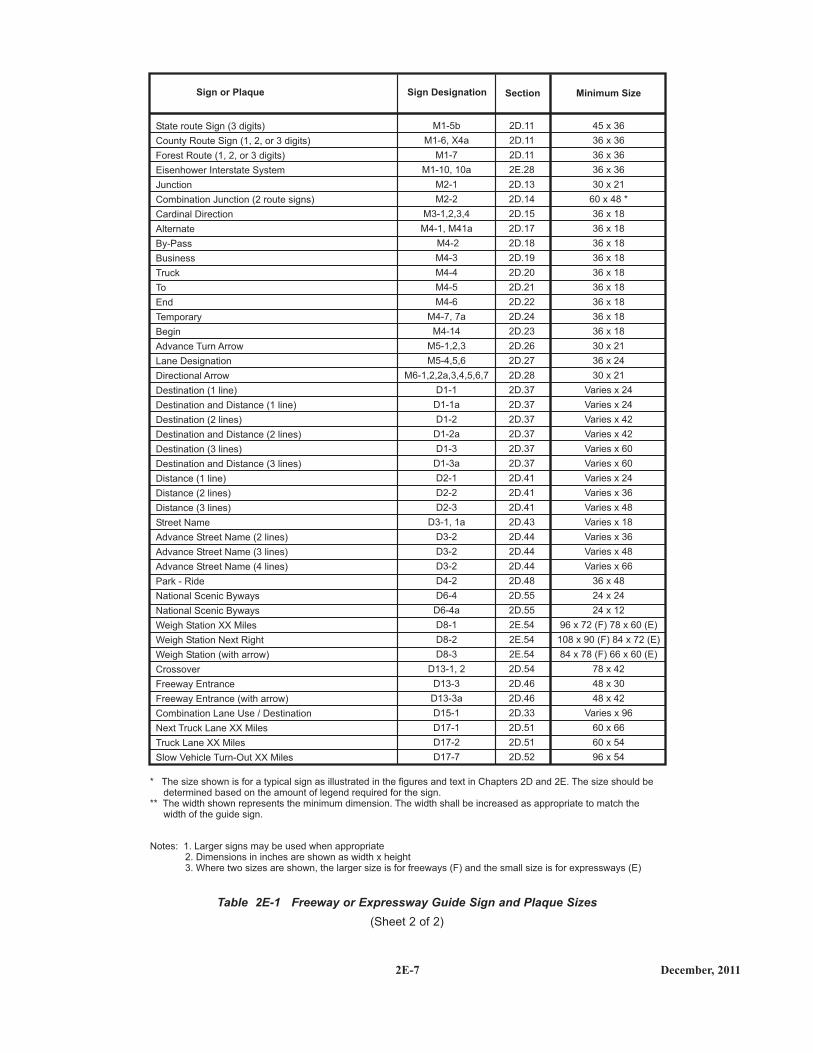
Except as provided in Section 2A.11, the sizes of freewayand expressway guide signs that have standardized designsshall be as shown in Table 2E-1.
Section 2A.11 contains information regarding the applic-ability of the various columns in Table 2E-1.
Signs larger than those shown in Table 2E-1 may be used(see Section 2A.11).
OPTION:OPTION:
SUPPORT:SUPPORT:
STANDARD:STANDARD:
STANDARD:STANDARD:
SUPPORT:SUPPORT:
GUIDANCE:GUIDANCE:
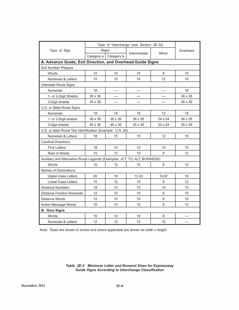
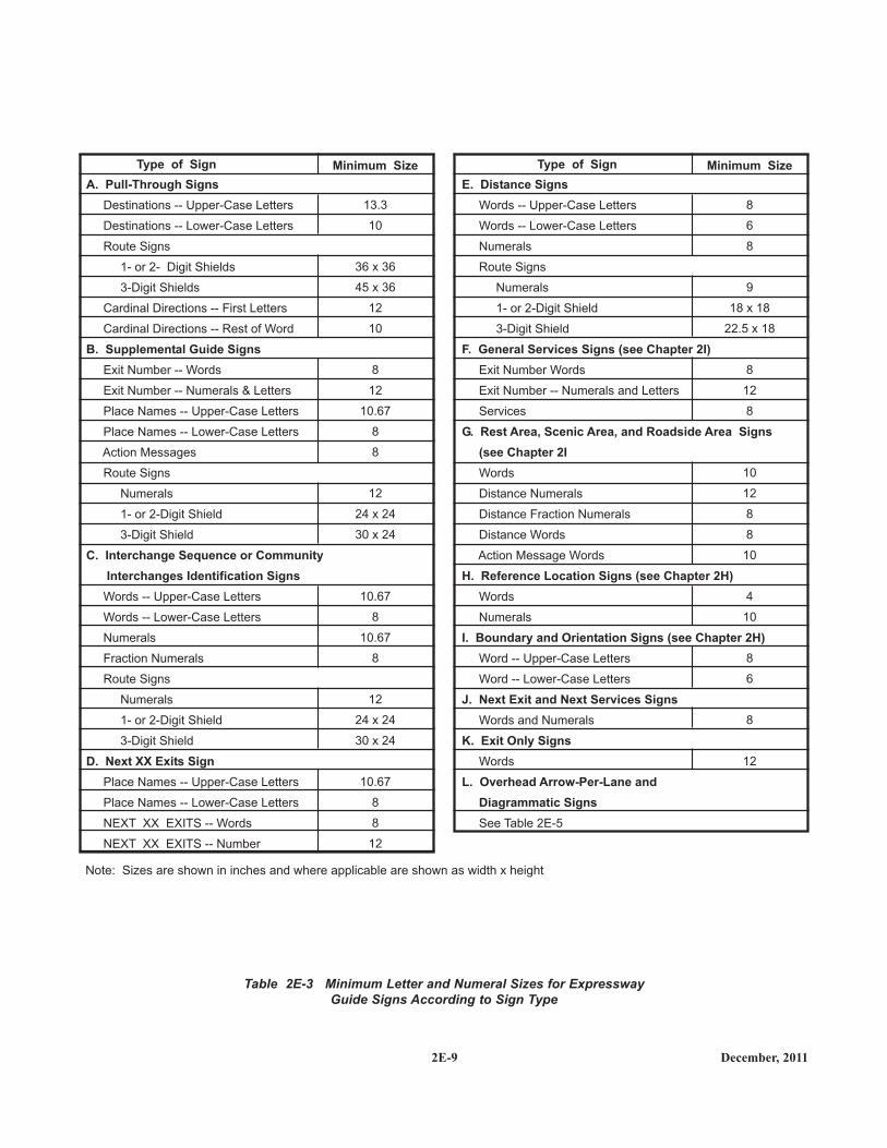
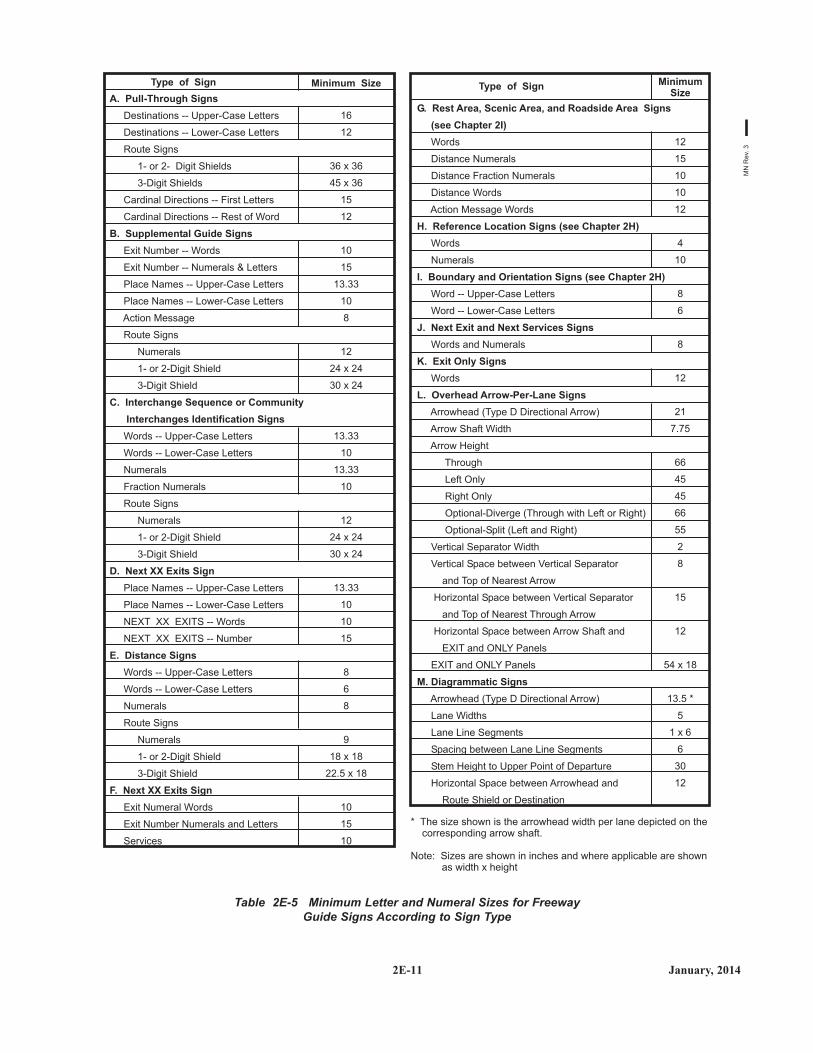
For all freeway and expressway signs that do not have astandardized design, the message dimensions shall bedetermined first, and the outside sign dimensionssecondarily. Word messages in the legend of expresswayguide signs shall be in letters at least 8 inches high. Largerlettering shall be used for major guide signs at or in advanceof interchanges and for all overhead signs. Minimumnumeral and letter sizes for expressway guide signsaccording to interchange classification, type of sign, andcomponent of sign legend shall be as shown in Tables 2E-2and 2E-3. Minimum numeral and letter sizes for freewayguide signs according to interchange classification, type ofsign, and component of sign legend shall be as shown inTables 2E-4 and 2E-5. All names of places, streets, andhighways on freeway and expressway guide signs shall becomposed of lower-case letters with initial upper-caseletters. The letters and the numerals used shall be SeriesE(M) of the FHWA "Standard Highway Signs andMarkings" book (see Section 1A.11). The nominal loopheight of the lower-case letters shall be 3/4 of the height ofthe initial upper-case letter (see Paragraph 2 of Section 2D.5for additional information on the specification of letterheights). Other word legends shall be composed of upper-case letters. Interline and edge spacing shall be as providedin Section 2E.15.
Lettering size on freeway and expressway signs shall bethe same for both rural and urban conditions.
.
Sign size is determined primarily in terms of the length ofthe message and the size of the lettering necessary for properlegibility. Letter style and height, and arrow design havebeen standardized for freeway and expressway signs toassure uniform and effective application.
Designs for upper-case and lower-case alphabets togetherwith tables of recommended letter spacing, are shown in theFHWA "Standard Highway Signs and Markings" book andthe MnDOT "Standard Signs Manual".
Freeway lettering sizes (see Tables 2E-4 and 2E-5) shouldbe used when expressway geometric design is comparable tofreeway standards.
Other sign letter size requirements not specificallyidentified elsewhere in this Manual should be guided bythese specifications. Abbreviations (see Section 2E.17)should be kept to a minimum.
STANDARD:STANDARD:
GUIDANCE:GUIDANCE:
SUPPORT:SUPPORT:
2E-5 December, 2011
July, 2012 2E-6
Table 2E-1 Freeway or Expressway Guide Sign and Plaque Sizes(Sheet 1 of 2)
MN
Rev
. 1
December, 20112E-7
Table 2E-1 Freeway or Expressway Guide Sign and Plaque Sizes(Sheet 2 of 2)
2E-8December, 2011
Table 2E-2 Minimum Letter and Numeral Sizes for ExpresswayGuide Signs According to Interchange Classification
A
B. Gore Signs
Exit Number Plaques
Words
Numerals & Letters
Interstate Route Signs
Numerals
1- or 2-Digit Shields
3-Digit shields
U.S. or State Route Signs
Numerals
1- or 2-Digit shields
3-digit shields
U.S. or state Route Text Identification (Example: U.S. 56)
Numerals & Letters
Cardinal Directions
First Letters
Rest of Words
Auxiliary and Alternative Route Legends (Examples: JCT, TO, ALT, BUSINESS)
Words
Names of Destinations
Upper-Case Letters
Lower-Case Letters
Distance Numbers
Distance Fraction Numerals
Distance Words
Action Message Words
Words
Numerals & Letters
Category a Category bIntermediate Minor
MajorType of Sign
Type of Interchange (see Section 2E.32)
Note: Sizes are shown in inches and where applicable are shown as width x height.
Overhead
10
15
18
36 x 36
45 x 36
18
36 x 36
45 x 36
18
18
15
15
20
15
18
12
12
10
10
12
10
15
---
---
---
18
36 x 36
45 x 36
15
15
12
12
16
12
15
10
10
10
10
12
10
15
---
---
---
18
36 x 36
45 x 36
15
12
10
10
13.33
10
12
10
10
10
10
12
8
12
---
---
---
12
24 x 24
30 x 24
12
10
8
8
10.67
8
10
8
8
8
8
10
10
15
18
36 x 36
45 x 36
18
36 x 36
45 x 36
15
15
12
12
16
12
15
10
10
10
---
---
A. Advance Guide, Exit Direction, and Overhead Guide Signs
2E-9 December, 2011
Table 2E-3 Minimum Letter and Numeral Sizes for ExpresswayGuide Signs According to Sign Type
A. Pull-Through Signs
B. Supplemental Guide Signs
C. Interchange Sequence or Community
Interchanges Identification Signs
D. Next XX Exits Sign
Destinations -- Upper-Case Letters
Destinations -- Lower-Case Letters
Route Signs
1- or 2- Digit Shields
3-Digit Shields
Cardinal Directions -- First Letters
Cardinal Directions -- Rest of Word
Exit Number -- Words
Exit Number -- Numerals & Letters
Place Names -- Upper-Case Letters
Place Names -- Lower-Case Letters
Action Messages
Route Signs
Numerals
1- or 2-Digit Shield
3-Digit Shield
Words -- Upper-Case Letters
Words -- Lower-Case Letters
Numerals
Fraction Numerals
Route Signs
Numerals
1- or 2-Digit Shield
3-Digit Shield
Place Names -- Upper-Case Letters
Place Names -- Lower-Case Letters
NEXT XX EXITS -- Words
NEXT XX EXITS -- Number
E. Distance Signs
F. General Services Signs (see Chapter 2I)
G. Rest Area, Scenic Area, and Roadside Area Signs
(see Chapter 2I
H. Reference Location Signs (see Chapter 2H)
I. Boundary and Orientation Signs (see Chapter 2H)
J. Next Exit and Next Services Signs
K. Exit Only Signs
L. Overhead Arrow-Per-Lane and
Diagrammatic Signs
Words -- Upper-Case Letters
Words -- Lower-Case Letters
Numerals
Route Signs
Numerals
1- or 2-Digit Shield
3-Digit Shield
Exit Number Words
Exit Number -- Numerals and Letters
Services
Words
Distance Numerals
Distance Fraction Numerals
Distance Words
Action Message Words
Words
Numerals
Word -- Upper-Case Letters
Word -- Lower-Case Letters
Words and Numerals
Words
See Table 2E-5
Minimum Size Minimum SizeType of Sign Type of Sign
13.3
10
36 x 36
45 x 36
12
10
8
12
10.67
8
8
12
24 x 24
30 x 24
10.67
8
10.67
8
12
24 x 24
30 x 24
10.67
8
8
12
8
6
8
9
18 x 18
22.5 x 18
8
12
8
10
12
8
8
10
4
10
8
6
8
12
Note: Sizes are shown in inches and where applicable are shown as width x height
2E-10December, 2011
Table 2E-4 Minimum Letter and Numeral Sizes for FreewayGuide Signs According to Interchange Classification
A
B. Gore Signs
Exit Number Plaques
Words
Numerals & Letters
Interstate Route Signs
Numerals
1- or 2-Digit Shields
3-Digit shields
U.S. or State Route Signs
Numerals
1- or 2-Digit shields
3-digit shields
U.S. or state Route Text Identification (Example: U.S. 56)
Numerals & Letters
Cardinal Directions
First Letters
Rest of Words
Auxiliary and Alternative Route Legends (Examples: JCT, TO, ALT, BUSINESS)
Words
Names of Destinations
Upper-Case Letters
Lower-Case Letters
Distance Numbers
Distance Fraction Numerals
Distance Words
Action Message Words
Words
Numerals & Letters
Category a Category bIntermediate Minor
MajorType of Sign
Type of Interchange (see Section 2E.32)
Note: 1. Sizes are shown in inches and where applicable are shown as width x height.2. Slanted line (/) signifies separation of desirable and minimum sizes.
Overhead
10
15
24/18
48 x 48/36 x 36
60 x 48/45 x 36
24/18
48 x 48/36 x 36
60 x 48/45 x 36
18
18
15
15
20
15
18
12
12
12
12
18
10
15
---
---
---
18
36 x 36
45 x 36
18/15
15
12
12
20
15
18/15
12/10
12/10
12/10
10
12
10
15
---
---
---
18
36 x 36
45 x 36
15
15
12
12
16
12
15
10
10
10
12
18
10
15
---
---
---
12
24 x 24
30 x 24
12
10
8
8
13.33
10
12
8
8
8
8
12
10
15
18
36 x 36
45 x 36
18
36 x 36
45 x 36
15
15
12
12
16
12
15
10
10
10
---
---
A. Advance Guide, Exit Direction, and Overhead Guide Signs
2E-11 January, 2014
Table 2E-5 Minimum Letter and Numeral Sizes for FreewayGuide Signs According to Sign Type
A. Pull-Through Signs
B. Supplemental Guide Signs
C. Interchange Sequence or Community
Interchanges Identification Signs
D. Next XX Exits Sign
E. Distance Signs
F. Next XX Exits Sign
Destinations -- Upper-Case Letters
Destinations -- Lower-Case Letters
Route Signs
1- or 2- Digit Shields
3-Digit Shields
Cardinal Directions -- First Letters
Cardinal Directions -- Rest of Word
Exit Number -- Words
Exit Number -- Numerals & Letters
Place Names -- Upper-Case Letters
Place Names -- Lower-Case Letters
Action Message
Route Signs
Numerals
1- or 2-Digit Shield
3-Digit Shield
Words -- Upper-Case Letters
Words -- Lower-Case Letters
Numerals
Fraction Numerals
Route Signs
Numerals
1- or 2-Digit Shield
3-Digit Shield
Place Names -- Upper-Case Letters
Place Names -- Lower-Case Letters
NEXT XX EXITS -- Words
NEXT XX EXITS -- Number
Words -- Upper-Case Letters
Words -- Lower-Case Letters
Numerals
Route Signs
Numerals
1- or 2-Digit Shield
3-Digit Shield
Exit Numeral Words
Exit Number Numerals and Letters
Services
Minimum SizeType of Sign
16
12
36 x 36
45 x 36
15
12
10
15
13.33
10
8
12
24 x 24
30 x 24
13.33
10
13.33
10
12
24 x 24
30 x 24
13.33
10
10
15
8
6
8
9
18 x 18
22.5 x 18
10
15
10
G. Rest Area, Scenic Area, and Roadside Area Signs
(see Chapter 2I)
H. Reference Location Signs (see Chapter 2H)
I. Boundary and Orientation Signs (see Chapter 2H)
J. Next Exit and Next Services Signs
K. Exit Only Signs
L. Overhead Arrow-Per-Lane Signs
M. Diagrammatic Signs
Words
Distance Numerals
Distance Fraction Numerals
Distance Words
Action Message Words
Words
Numerals
Word -- Upper-Case Letters
Word -- Lower-Case Letters
Words and Numerals
Words
Arrowhead (Type D Directional Arrow)
Arrow Shaft Width
Arrow Height
Through
Left Only
Right Only
Optional-Diverge (Through with Left or Right)
Optional-Split (Left and Right)
Vertical Separator Width
Vertical Space between Vertical Separator
and Top of Nearest Arrow
Horizontal Space between Vertical Separator
and Top of Nearest Through Arrow
Horizontal Space between Arrow Shaft and
EXIT and ONLY Panels
EXIT and ONLY Panels
Arrowhead (Type D Directional Arrow)
Lane Widths
Lane Line Segments
Spacing between Lane Line Segments
Stem Height to Upper Point of Departure
Horizontal Space between Arrowhead and
Route Shield or Destination
MinimumSize
Type of Sign
12
15
10
10
12
4
10
8
6
8
12
21
7.75
66
45
45
66
55
2
8
15
12
54 x 18
13.5 *
5
1 x 6
6
30
12
* The size shown is the arrowhead width per lane depicted on thecorresponding arrow shaft.
Note: Sizes are shown in inches and where applicable are shownas width x height
MN
Rev
. 3
December, 2011 2E-12
2E.17 Abbreviations
Abbreviations should be kept to a minimum; however,they are useful when complete destination messages produceexcessively long signs. If used, abbreviations should beunmistakably recognized by road users (see Section 1A.15).Longer commonly used words that are not part of a propername and are readily recognizable, such as Street,Boulevard, and Avenue, should be abbreviated to expediterecognition of the sign legend by reducing the amount andcomplexity of the legend.
Periods, apostrophes, question marks, ampersands, orother punctuation or characters that are not letters, numerals,or hyphens should not be used in abbreviations, unlessnecessary to avoid confusion.
The solidus (slanted line or forward slash) is intended tobe used for fractions only and should not be used to separatewords on the same line of legend. Instead, a hyphen shouldbe used for this purpose, such as "CARS - TRUCKS."
The words NORTH, SOUTH, EAST, and WEST shall notbe abbreviated when used with route signs to indicatecardinal directions on guide signs.
2E.18 Symbols
Symbol designs shall be unmistakably like those shownin Appendix C of this Manual and the MnDOT “StandardSigns Manual”, and the Federal "Standard Highway Signsand Markings" book.
A special effort should be made to balance legendcomponents for maximum legibility of the symbol with therest of the sign.
Educational plaques may be used below symbol signswhere needed.
GUIDANCE:GUIDANCE:
STANDARD:STANDARD:
STANDARD:STANDARD:
GUIDANCE:GUIDANCE:
OPTION:OPTION:
A sign mounted over a particular roadway lane to whichit applies might have to be limited in horizontal dimensionto the width of the lane, so that another sign can be placedover an adjacent lane. The necessity to maintain propervertical clearance might also place a further limitation on thesize of the overhead sign and the legend that can be accom-modated.
2E.15 lnterline and Edge Spacing
Interline spacing of upper-case letters should be approxi-mately three-fourths the average of upper-case letter heightsin adjacent lines of letters.
The spacings to the top and bottom borders should beequal to the average of the letter height of the adjacent lineof letters. The lateral spacing to the vertical borders shouldbe essentially the same as the height of the largest letter.
2E.16 Sign Borders
Signs shall have a border of the same color as the legendin order to outline their distinctive shape and thereby givethem easy recognition and a finished appearance.
For guide signs larger than 120 x 72 inches, the bordershould have a width of 2 inches. For smaller guide signs, aborder width of 1.25 inches should be used, but the widthshould not exceed the stroke width of the lettering of theprincipal legend on the sign.
Corner radii of sign borders should be 1/8 of theminimum sign dimension on guide signs, except that theradii should not exceed 12 inches on any sign.
The sign material in the area outside of the corner radiusmay be trimmed.
SUPPORT:SUPPORT:
GUIDANCE:GUIDANCE:
STANDARD:STANDARD:
GUIDANCE:GUIDANCE:
OPTION:OPTION:
December, 20112E-13
2E.19 Arrows for Interchange Guide Signs
Arrows used on interchange guide signs shall be of thetypes shown in Figure 2D-2 and shall comply with theprovisions of this Section and Section 2D.8.
Except on Overhead Arrow-per-Lane guide signs (seeSection 2E.21) and on Exit Direction signs for lane drops(see Section 2E.24), and except as provided in the followingOption and the first paragraph of the following Standard,directional arrows on all overhead and post-mounted ExitDirection signs shall point diagonally upward and shall belocated on the side of the sign consistent with the directionof the exiting movement.
On post-mounted Exit Direction signs that are locatedwhere a directional arrow to the side of the legend farthestfrom the roadway might create an unusually wide sign thatlimits the road user's view of the arrow, the directional arrowmay be placed at the bottom portion of the sign, centeredunder the legend.
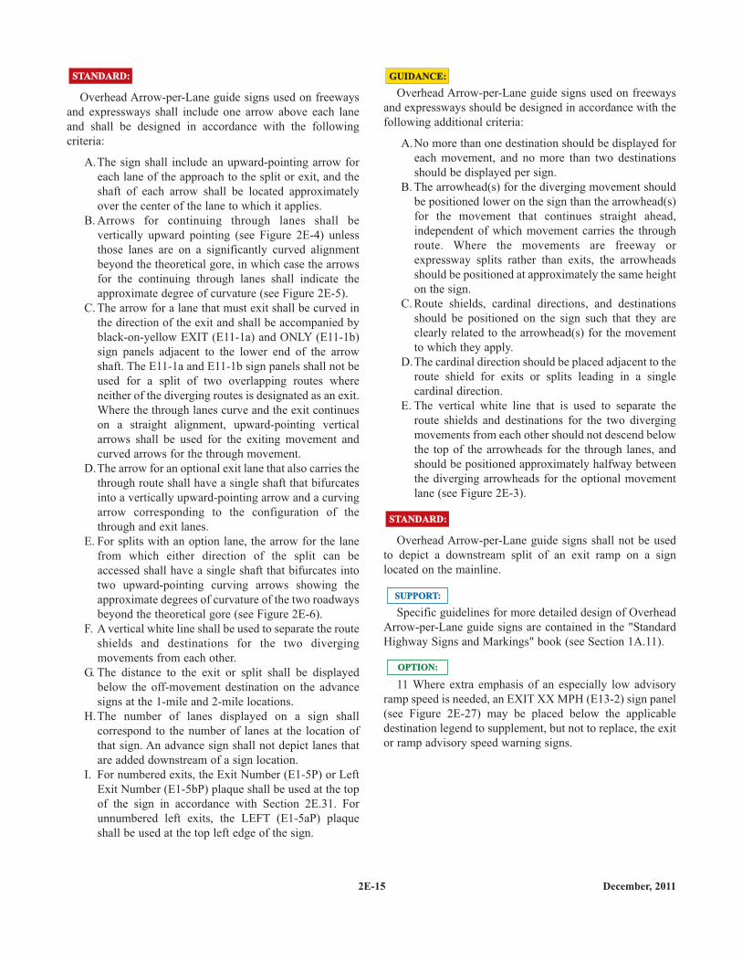
Directional arrows on guide signs for multi-lane exitsshall be positioned below the legend approximately over thecenter of each lane to which the arrow applies (see Figures2E-4 and 2E-8).
STANDARD:STANDARD:
OPTION:OPTION:
STANDARD:STANDARD:
On overhead signs where down arrows are used toindicate a lane to be followed, a down arrow shall bepositioned approximately over the center of each lane andshall point vertically downward toward the approximatecenter of that lane. Down arrows shall be used only onoverhead guide signs that restrict the use of specific lanes totraffic bound for the destination(s) and/or route(s) indicatedby these arrows. Down arrows shall not be used unless anarrow can be located over and pointed to the approximatecenter of each lane that can be used to reach the destinationdisplayed on the sign.
If down arrows are used, having more than one downarrow pointing to the same lane on a single overhead sign (oron multiple signs on the same overhead sign structure) shallnot be permitted.
Directional and down arrows for use on guide signs areshown in Figure 2D-2. Detailed drawings and standardizedsizes based on ranges of letter heights for these arrows areprovided in the MnDOT “Standard Signs Manual”, and theFHWA "Standard Highway Signs and Markings" book (seeSection 1A.11). Information on the dimensions for arrowsused in Overhead Arrow-per-Lane and Diagrammatic guidesigning is also provided in the MnDOT “Standard SignsManual”,and FHWA "Standard Highway Signs andMarkings" book.
SUPPORT:SUPPORT:
E X I T 1 1
EA S T59 5
INTERSTATE
O N LYE X I T
A n n a p o l i s M i t c h e l l v i l l e
7 6
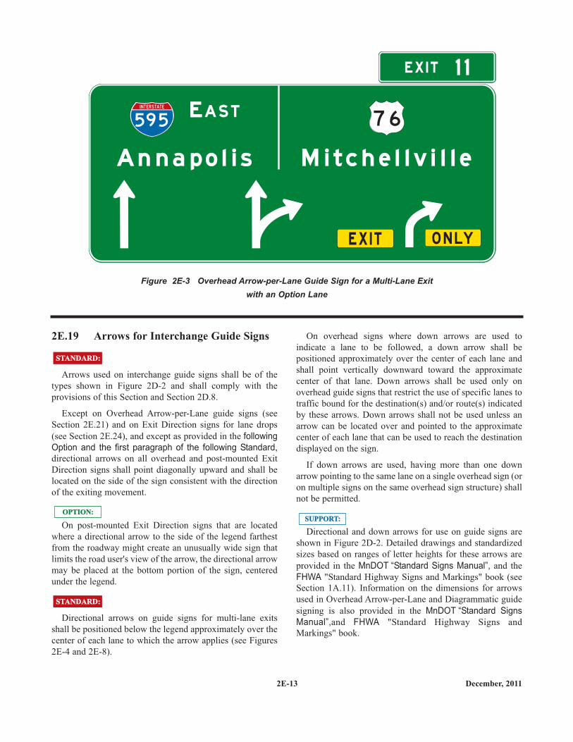
Figure 2E-3 Overhead Arrow-per-Lane Guide Sign for a Multi-Lane Exitwith an Option Lane
2E-14December, 2011
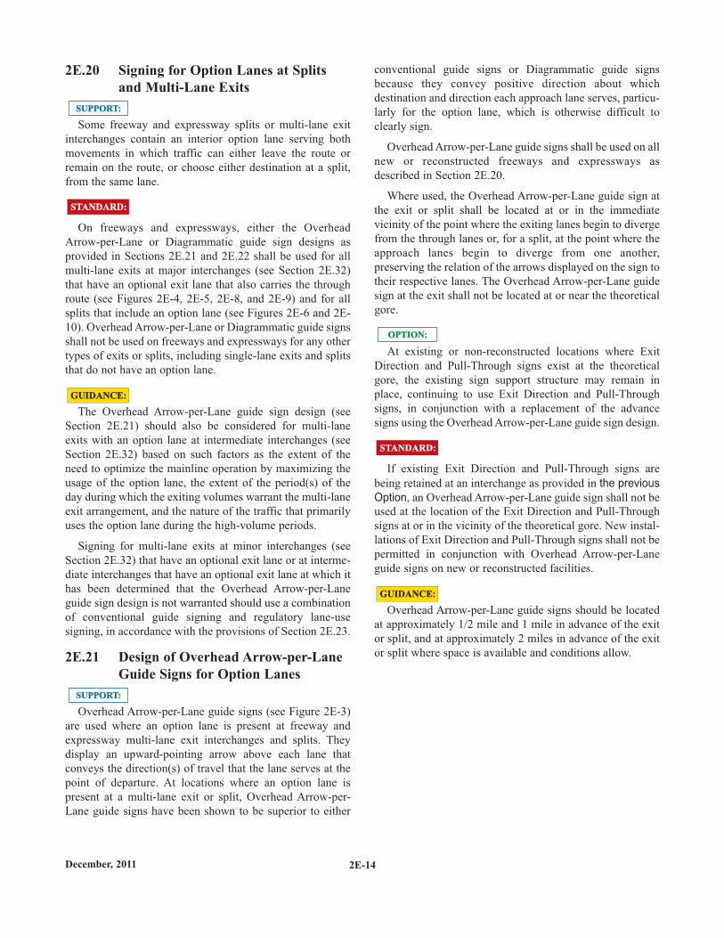
2E.20 Signing for Option Lanes at Splitsand Multi-Lane Exits
Some freeway and expressway splits or multi-lane exitinterchanges contain an interior option lane serving bothmovements in which traffic can either leave the route orremain on the route, or choose either destination at a split,from the same lane.
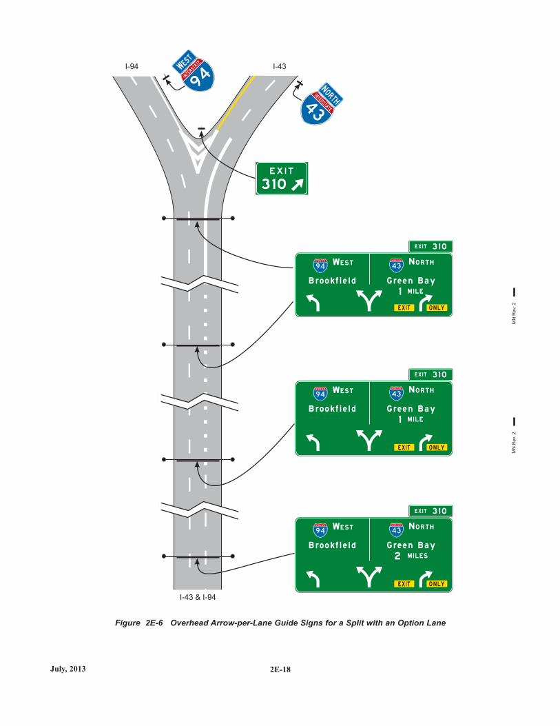
On freeways and expressways, either the OverheadArrow-per-Lane or Diagrammatic guide sign designs asprovided in Sections 2E.21 and 2E.22 shall be used for allmulti-lane exits at major interchanges (see Section 2E.32)that have an optional exit lane that also carries the throughroute (see Figures 2E-4, 2E-5, 2E-8, and 2E-9) and for allsplits that include an option lane (see Figures 2E-6 and 2E-10). Overhead Arrow-per-Lane or Diagrammatic guide signsshall not be used on freeways and expressways for any othertypes of exits or splits, including single-lane exits and splitsthat do not have an option lane.
The Overhead Arrow-per-Lane guide sign design (seeSection 2E.21) should also be considered for multi-laneexits with an option lane at intermediate interchanges (seeSection 2E.32) based on such factors as the extent of theneed to optimize the mainline operation by maximizing theusage of the option lane, the extent of the period(s) of theday during which the exiting volumes warrant the multi-laneexit arrangement, and the nature of the traffic that primarilyuses the option lane during the high-volume periods.
Signing for multi-lane exits at minor interchanges (seeSection 2E.32) that have an optional exit lane or at interme-diate interchanges that have an optional exit lane at which ithas been determined that the Overhead Arrow-per-Laneguide sign design is not warranted should use a combinationof conventional guide signing and regulatory lane-usesigning, in accordance with the provisions of Section 2E.23.
2E.21 Design of Overhead Arrow-per-LaneGuide Signs for Option Lanes
Overhead Arrow-per-Lane guide signs (see Figure 2E-3)are used where an option lane is present at freeway andexpressway multi-lane exit interchanges and splits. Theydisplay an upward-pointing arrow above each lane thatconveys the direction(s) of travel that the lane serves at thepoint of departure. At locations where an option lane ispresent at a multi-lane exit or split, Overhead Arrow-per-Lane guide signs have been shown to be superior to either
SUPPORT:SUPPORT:
GUIDANCE:GUIDANCE:
STANDARD:STANDARD:
SUPPORT:SUPPORT:
conventional guide signs or Diagrammatic guide signsbecause they convey positive direction about whichdestination and direction each approach lane serves, particu-larly for the option lane, which is otherwise difficult toclearly sign.
Overhead Arrow-per-Lane guide signs shall be used on allnew or reconstructed freeways and expressways asdescribed in Section 2E.20.
Where used, the Overhead Arrow-per-Lane guide sign atthe exit or split shall be located at or in the immediatevicinity of the point where the exiting lanes begin to divergefrom the through lanes or, for a split, at the point where theapproach lanes begin to diverge from one another,preserving the relation of the arrows displayed on the sign totheir respective lanes. The Overhead Arrow-per-Lane guidesign at the exit shall not be located at or near the theoreticalgore.
At existing or non-reconstructed locations where ExitDirection and Pull-Through signs exist at the theoreticalgore, the existing sign support structure may remain inplace, continuing to use Exit Direction and Pull-Throughsigns, in conjunction with a replacement of the advancesigns using the Overhead Arrow-per-Lane guide sign design.
If existing Exit Direction and Pull-Through signs arebeing retained at an interchange as provided in the previousOption, an Overhead Arrow-per-Lane guide sign shall not beused at the location of the Exit Direction and Pull-Throughsigns at or in the vicinity of the theoretical gore. New instal-lations of Exit Direction and Pull-Through signs shall not bepermitted in conjunction with Overhead Arrow-per-Laneguide signs on new or reconstructed facilities.
Overhead Arrow-per-Lane guide signs should be locatedat approximately 1/2 mile and 1 mile in advance of the exitor split, and at approximately 2 miles in advance of the exitor split where space is available and conditions allow.
STANDARD:STANDARD:
GUIDANCE:GUIDANCE:
OPTION:OPTION:
2E-15 December, 2011
Overhead Arrow-per-Lane guide signs used on freewaysand expressways shall include one arrow above each laneand shall be designed in accordance with the followingcriteria:
A.The sign shall include an upward-pointing arrow foreach lane of the approach to the split or exit, and theshaft of each arrow shall be located approximatelyover the center of the lane to which it applies.
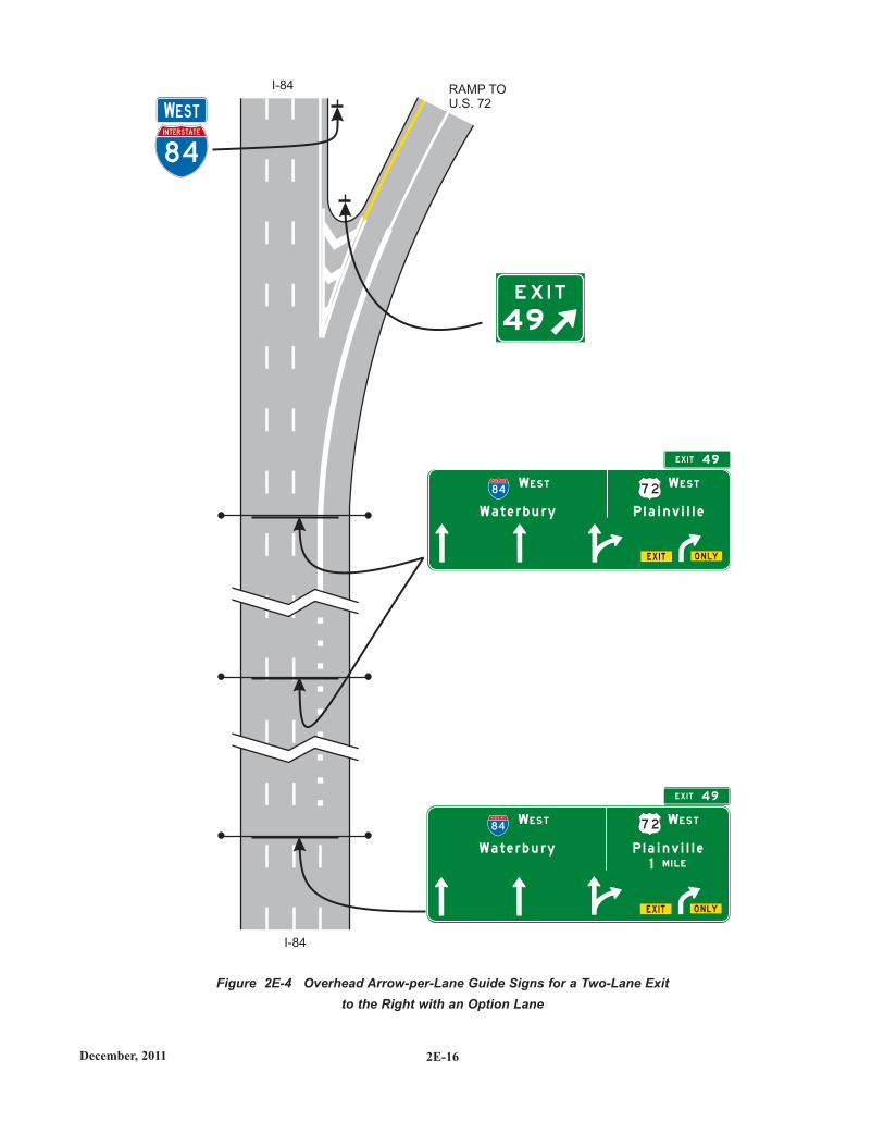
B. Arrows for continuing through lanes shall bevertically upward pointing (see Figure 2E-4) unlessthose lanes are on a significantly curved alignmentbeyond the theoretical gore, in which case the arrowsfor the continuing through lanes shall indicate theapproximate degree of curvature (see Figure 2E-5).
C. The arrow for a lane that must exit shall be curved inthe direction of the exit and shall be accompanied byblack-on-yellow EXIT (E11-1a) and ONLY (E11-1b)sign panels adjacent to the lower end of the arrowshaft. The E11-1a and E11-1b sign panels shall not beused for a split of two overlapping routes whereneither of the diverging routes is designated as an exit.Where the through lanes curve and the exit continueson a straight alignment, upward-pointing verticalarrows shall be used for the exiting movement andcurved arrows for the through movement.
D.The arrow for an optional exit lane that also carries thethrough route shall have a single shaft that bifurcatesinto a vertically upward-pointing arrow and a curvingarrow corresponding to the configuration of thethrough and exit lanes.
E. For splits with an option lane, the arrow for the lanefrom which either direction of the split can beaccessed shall have a single shaft that bifurcates intotwo upward-pointing curving arrows showing theapproximate degrees of curvature of the two roadwaysbeyond the theoretical gore (see Figure 2E-6).
F. A vertical white line shall be used to separate the routeshields and destinations for the two divergingmovements from each other.
G. The distance to the exit or split shall be displayedbelow the off-movement destination on the advancesigns at the 1-mile and 2-mile locations.
H.The number of lanes displayed on a sign shallcorrespond to the number of lanes at the location ofthat sign. An advance sign shall not depict lanes thatare added downstream of a sign location.
I. For numbered exits, the Exit Number (E1-5P) or LeftExit Number (E1-5bP) plaque shall be used at the topof the sign in accordance with Section 2E.31. Forunnumbered left exits, the LEFT (E1-5aP) plaqueshall be used at the top left edge of the sign.
STANDARD:STANDARD:
Overhead Arrow-per-Lane guide signs used on freewaysand expressways should be designed in accordance with thefollowing additional criteria:
A.No more than one destination should be displayed foreach movement, and no more than two destinationsshould be displayed per sign.
B. The arrowhead(s) for the diverging movement shouldbe positioned lower on the sign than the arrowhead(s)for the movement that continues straight ahead,independent of which movement carries the throughroute. Where the movements are freeway orexpressway splits rather than exits, the arrowheadsshould be positioned at approximately the same heighton the sign.
C. Route shields, cardinal directions, and destinationsshould be positioned on the sign such that they areclearly related to the arrowhead(s) for the movementto which they apply.
D.The cardinal direction should be placed adjacent to theroute shield for exits or splits leading in a singlecardinal direction.
E. The vertical white line that is used to separate theroute shields and destinations for the two divergingmovements from each other should not descend belowthe top of the arrowheads for the through lanes, andshould be positioned approximately halfway betweenthe diverging arrowheads for the optional movementlane (see Figure 2E-3).
Overhead Arrow-per-Lane guide signs shall not be usedto depict a downstream split of an exit ramp on a signlocated on the mainline.
Specific guidelines for more detailed design of OverheadArrow-per-Lane guide signs are contained in the "StandardHighway Signs and Markings" book (see Section 1A.11).
11 Where extra emphasis of an especially low advisoryramp speed is needed, an EXIT XX MPH (E13-2) sign panel(see Figure 2E-27) may be placed below the applicabledestination legend to supplement, but not to replace, the exitor ramp advisory speed warning signs.
STANDARD:STANDARD:
GUIDANCE:GUIDANCE:
OPTION:OPTION:
SUPPORT:SUPPORT:
2E-16December, 2011
Figure 2E-4 Overhead Arrow-per-Lane Guide Signs for a Two-Lane Exitto the Right with an Option Lane
84
INTERSTATE
WWESTEST
O N LY
O N LY
E X I T
E X I T
WE S T
WES T
WES T
WES T
EX I T
E X I T
4 9
4 9
84
INTERSTATE
8 4
INTERSTATE
Wa t e r b u ry
W a t e r b u ry
P l a i n v i l l e
P l a i n v i l l e1 M I L E
I-84
I-84
RAMP TO
U.S. 72
49
7 2
7 2
2E-17 December, 2011
Figure 2E-5 Overhead Arrow-per-Lane Guide Signs for a Two-Lane Exit to the Rightwith an Option Lane (Through Lanes Curve to the Left)
I-295
I-295
RAMP TO
U.S. 130
295IN
TERSTATESS O
UTH
O UTH
1 3 0
SO UTH
TO
1 3
29 5
INTERSTATE
2 9 5
INTERSTATE
O N LY
O N LY
E X I T
E X I T
D e e pwa t e r
D e e pwa t e r
B r i d g e p o rt
B r i d g e p o rt
1 M I L E
E X I T 1 3
E X I T 1 3
S O U T H
S O U T H
S O U T H
S O U T H
1 3 0
1 3 0
2E-18July, 2013
Figure 2E-6 Overhead Arrow-per-Lane Guide Signs for a Split with an Option Lane
I-94 I-43
3 1 0
O N LY
O N LY
O N LY
E X I T
E X I T
E X I T
B ro o k f i e l d
B ro o k f i e l d
B ro o k f i e l d
G re e n B a y
G re e n B a y
G re e n B a y
2 M I L E S
1 M I L E
1 M I L E
E X I T 3 1 0
EX I T 3 1 0
EX I T 3 1 0
WWEST
EST
94IN
TERSTATE
NNORTH
ORTH4
3
INTERSTATE
9 4
INTERSTATE
9 4
INTERSTATE
9 4
INTERSTATE
4 3
INTERSTATE
4 3
INTERSTATE
4 3
INTERSTATE
N O R T H
N O R T H
N O R T H
WES T
WES T
WES T
I-43 & I-94
MN
Rev
. 2M
N R
ev. 2
2E-19 December, 2011
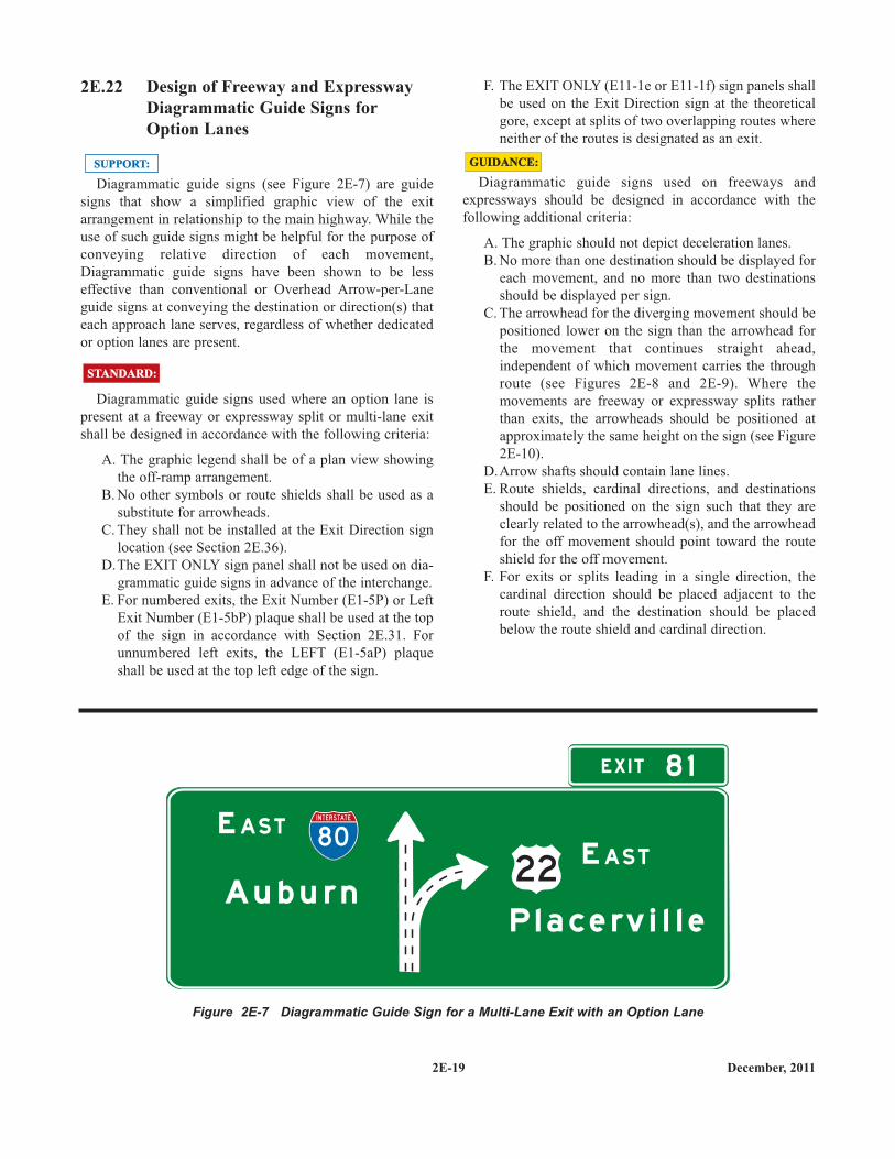
2E.22 Design of Freeway and ExpresswayDiagrammatic Guide Signs forOption Lanes
Diagrammatic guide signs (see Figure 2E-7) are guidesigns that show a simplified graphic view of the exitarrangement in relationship to the main highway. While theuse of such guide signs might be helpful for the purpose ofconveying relative direction of each movement,Diagrammatic guide signs have been shown to be lesseffective than conventional or Overhead Arrow-per-Laneguide signs at conveying the destination or direction(s) thateach approach lane serves, regardless of whether dedicatedor option lanes are present.
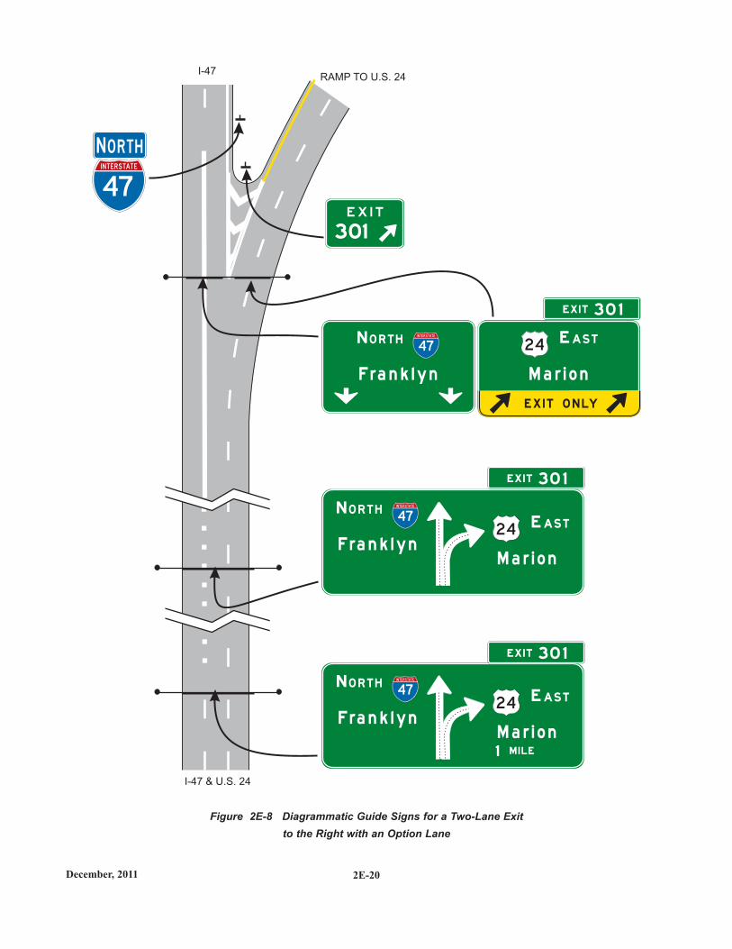
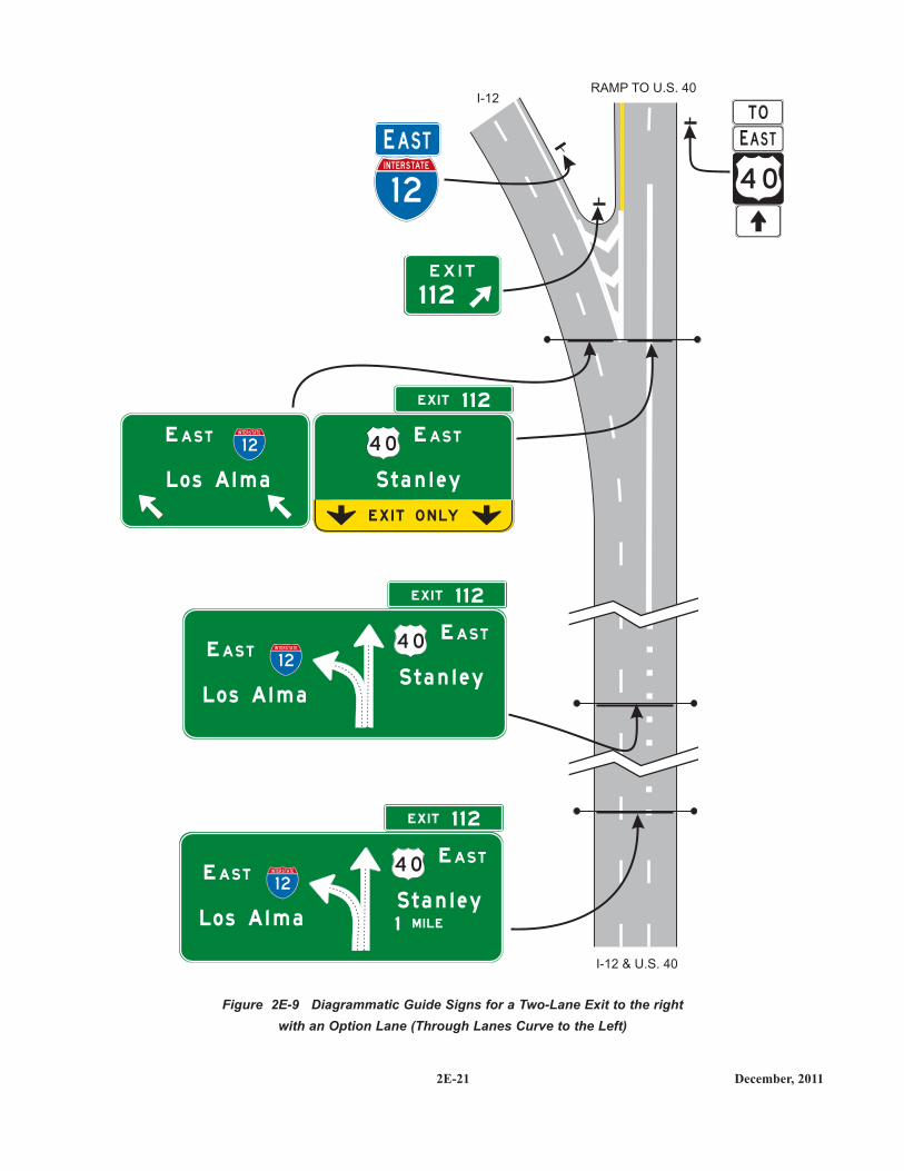
Diagrammatic guide signs used where an option lane ispresent at a freeway or expressway split or multi-lane exitshall be designed in accordance with the following criteria:
A. The graphic legend shall be of a plan view showingthe off-ramp arrangement.
B. No other symbols or route shields shall be used as asubstitute for arrowheads.
C. They shall not be installed at the Exit Direction signlocation (see Section 2E.36).
D.The EXIT ONLY sign panel shall not be used on dia-grammatic guide signs in advance of the interchange.
E. For numbered exits, the Exit Number (E1-5P) or LeftExit Number (E1-5bP) plaque shall be used at the topof the sign in accordance with Section 2E.31. Forunnumbered left exits, the LEFT (E1-5aP) plaqueshall be used at the top left edge of the sign.
STANDARD:STANDARD:
SUPPORT:SUPPORT:
F. The EXIT ONLY (E11-1e or E11-1f) sign panels shallbe used on the Exit Direction sign at the theoreticalgore, except at splits of two overlapping routes whereneither of the routes is designated as an exit.
Diagrammatic guide signs used on freeways andexpressways should be designed in accordance with thefollowing additional criteria:
A. The graphic should not depict deceleration lanes. B. No more than one destination should be displayed for
each movement, and no more than two destinationsshould be displayed per sign.
C. The arrowhead for the diverging movement should bepositioned lower on the sign than the arrowhead forthe movement that continues straight ahead,independent of which movement carries the throughroute (see Figures 2E-8 and 2E-9). Where themovements are freeway or expressway splits ratherthan exits, the arrowheads should be positioned atapproximately the same height on the sign (see Figure2E-10).
D.Arrow shafts should contain lane lines. E. Route shields, cardinal directions, and destinations
should be positioned on the sign such that they areclearly related to the arrowhead(s), and the arrowheadfor the off movement should point toward the routeshield for the off movement.
F. For exits or splits leading in a single direction, thecardinal direction should be placed adjacent to theroute shield, and the destination should be placedbelow the route shield and cardinal direction.
GUIDANCE:GUIDANCE:
Figure 2E-7 Diagrammatic Guide Sign for a Multi-Lane Exit with an Option Lane
A u b u r nP l a c e rv i l l e
22
E X I T 8 1
E AS T
E AS T80
INTERSTATE
2E-20December, 2011
Figure 2E-8 Diagrammatic Guide Signs for a Two-Lane Exitto the Right with an Option Lane
I-47RAMP TO U.S. 24
I-47 & U.S. 24
47
INTERSTATE
NN O RTHO RTH
F ra n k l y n
F ra n k l y n
M a r i o n
M a r i o n
M I LE1
301
47
INTERSTATE
47
INTERSTATE
2 4
24
N O R T H
N O R T H
E AS T
E AS T
EX I T 30 1
EX I T 30 1
EX I T 30 1
E X I T O N LY
M a r i o n
24E AS T
F ra n k l y n
47
INTERSTATEN O R T H
2E-21 December, 2011
Figure 2E-9 Diagrammatic Guide Signs for a Two-Lane Exit to the rightwith an Option Lane (Through Lanes Curve to the Left)
I-12RAMP TO U.S. 40
I-12 & U.S. 40
1 2
INTERSTATE
1 1 2
Los A l m aS t a n l e y
1 2
INTERSTATE 4 0E AS T
E AS T
EX I T 1 1 2
EE ASTAST
EX I T 1 1 2
S t a n l e y
4 0E AS T
E X I T O N LY
E AS T
L o s A l m a
1 2
INTERSTATE
Los A l m a
1 2
INTERSTATEE AS T
EX I T 1 1 2
S t a n l e yM I LE1
4 0E AS T
4 0
EAST
TO
2E-22December, 2011
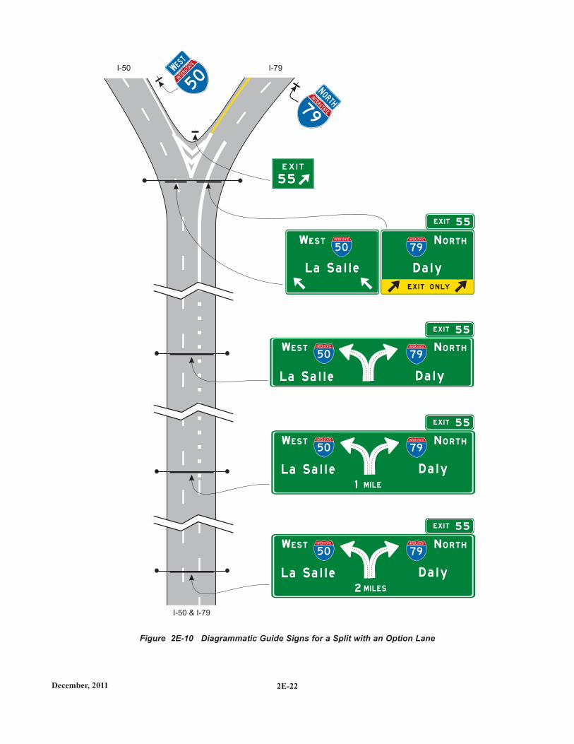
Figure 2E-10 Diagrammatic Guide Signs for a Split with an Option Lane
I-50 I-79
5 5
WWEST
EST
50IN
TERSTATE
NNORTH
ORTH7
9
INTERSTATE
I-50 & I-79
La S a l l e2 M I LES
D a l y
50
INTERSTATE
7 9
INTERSTATE
EX I T 5 5
N O R T HWES T
L a S a l l e1 M I L E
D a l y
50
INTERSTATE
7 9
INTERSTATE
EX I T 5 5
N O R T HWES T
L a S a l l e D a l y
EX I T 5 5
79
INTERSTATE N O R T H50
INTERSTATEWES T
D a l y
EX I T 5 5
79
INTERSTATE N O R T H
E X I T O N LY
L a S a l l e
50
INTERSTATEWES T
2E-23 December, 2011
Diagrammatic guide signs shall not be used at cloverleafinterchanges for the purpose of depicting successivedepartures from the mainline or separate downstreamdepartures from a collector-distributor roadway. The use ofDiagrammatic guide signs at cloverleaf interchanges shall belimited to the following cases:
A.Where the outer (non-loop) exit ramp of the cloverleafis a multi-lane exit having an optional exit lane thatalso carries the through route; and
B. At cloverleaf interchanges that include collector-distributor roadways, such as those illustrated inFigure 2E-36, that are accessed from the mainline bya multi-lane exit having an optional exit lane that alsocarries the through route. In this case, theDiagrammatic guide sign shall only show the config-uration of the lanes at the exit point to the collector-distributor roadway and not the entire interchangeconfiguration.
Specific guidelines for more detailed design ofDiagrammatic guide signs are contained in the FHWA"Standard Highway Signs and Markings" book (see Section1A.11).
For more specific guidelines on the detailed design ofthese types of signs, contact MnDOT, (see Office of Traffic,Safety and Technology, page ii).
Where extra emphasis of an especially low advisory rampspeed is needed, an EXIT XX MPH (E13-2) sign panel (seeFigure 2E-27) may be placed below the applicabledestination legend to supplement, but not to replace, the exitor ramp advisory speed warning signs.
2E.23 Signing for Intermediate and MinorInterchange Multi-Lane Exits withan Option Lane
Intermediate and minor multi-lane exits might have anoperational need for the presence of an option lane for onlythe peak period during which excessive queues mightotherwise develop if the option lane were not available. Insuch cases, the Overhead Arrow-per-Lane or Diagrammaticguide signing described for option lanes in Sections 2E.21and 2E.22 might not be practical, depending on the level ofuse of the option lane and the spacing of nearby inter-changes, particularly in non-rural areas.
SUPPORT:SUPPORT:
OPTION:OPTION:
STANDARD:STANDARD:
SUPPORT:SUPPORT:
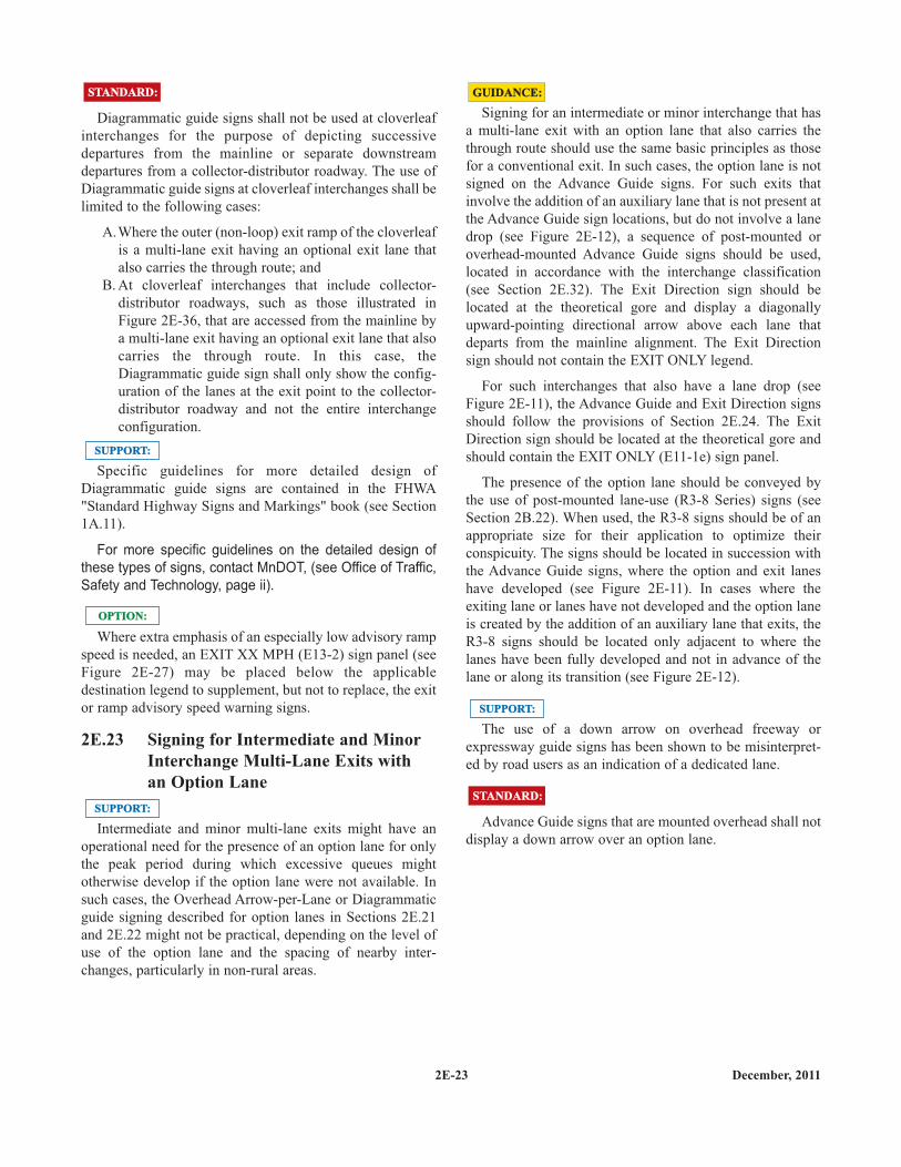
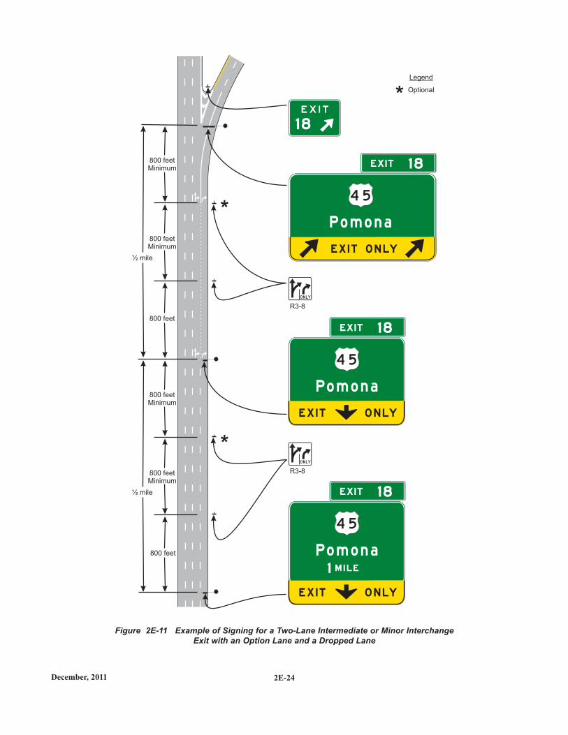
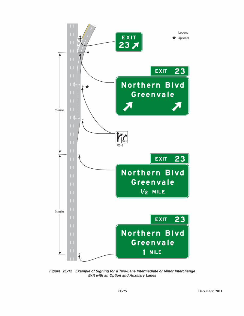
Signing for an intermediate or minor interchange that hasa multi-lane exit with an option lane that also carries thethrough route should use the same basic principles as thosefor a conventional exit. In such cases, the option lane is notsigned on the Advance Guide signs. For such exits thatinvolve the addition of an auxiliary lane that is not present atthe Advance Guide sign locations, but do not involve a lanedrop (see Figure 2E-12), a sequence of post-mounted oroverhead-mounted Advance Guide signs should be used,located in accordance with the interchange classification(see Section 2E.32). The Exit Direction sign should belocated at the theoretical gore and display a diagonallyupward-pointing directional arrow above each lane thatdeparts from the mainline alignment. The Exit Directionsign should not contain the EXIT ONLY legend.
For such interchanges that also have a lane drop (seeFigure 2E-11), the Advance Guide and Exit Direction signsshould follow the provisions of Section 2E.24. The ExitDirection sign should be located at the theoretical gore andshould contain the EXIT ONLY (E11-1e) sign panel.
The presence of the option lane should be conveyed bythe use of post-mounted lane-use (R3-8 Series) signs (seeSection 2B.22). When used, the R3-8 signs should be of anappropriate size for their application to optimize theirconspicuity. The signs should be located in succession withthe Advance Guide signs, where the option and exit laneshave developed (see Figure 2E-11). In cases where theexiting lane or lanes have not developed and the option laneis created by the addition of an auxiliary lane that exits, theR3-8 signs should be located only adjacent to where thelanes have been fully developed and not in advance of thelane or along its transition (see Figure 2E-12).
The use of a down arrow on overhead freeway orexpressway guide signs has been shown to be misinterpret-ed by road users as an indication of a dedicated lane.
Advance Guide signs that are mounted overhead shall notdisplay a down arrow over an option lane.
GUIDANCE:GUIDANCE:
STANDARD:STANDARD:
SUPPORT:SUPPORT:
2E-24December, 2011
Figure 2E-11 Example of Signing for a Two-Lane Intermediate or Minor InterchangeExit with an Option Lane and a Dropped Lane
1 8
EX I T 1 8
EX I T 1 8
EX I T 1 8
E X I T O N LY
P o m o n a
4 5
P o m o n a
P o m o n a
4 5
4 5
800 feet
800 feetMinimum
R3-8
R3-8
½ mile
½ mile
800 feetMinimum
800 feet
800 feetMinimum
800 feetMinimum
Legend
Optional
*
*
*
E X I T O N LY
E X I T O N LY
M I L E1
O N LY
O N LY
2E-25 December, 2011
Figure 2E-12 Example of Signing for a Two-Lane Intermediate or Minor InterchangeExit with an Option and Auxiliary Lanes
23
EX I T 23
EX I T 23
EX I T 23
R3-8
½ mile
½ mile
Legend
Optional
*
*
O N LY
N o rt h e r n B l v d
G re e n va l e
N o rt h e r n B l v d
G re e n va l e
M I L E1 2
N o rt h e r n B l v d
G re e n va l e
M I L E1
2E-26December, 2011
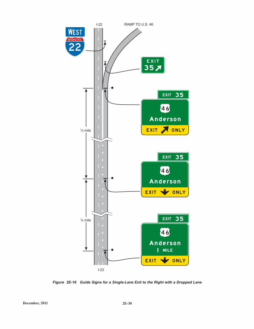
2E.24 Signing for Interchange Lane Drops
The provisions of this Section shall only apply to lanedrops at exits that do not have an optional exit lane. At exitsthat have an optional exit lane in addition to the droppedlane, the provisions of Sections 2E.20 through 2E.23 shallapply.
Major guide signs for all lane drops at interchanges shallbe mounted overhead. An EXIT ONLY sign panel shall beused for all interchange lane drops at which the throughroute is carried on the mainline.
Except on Overhead Arrow-per-Lane and Diagrammaticguide signs (See Sections 2E.20 through 2E.22), the EXITONLY (down arrow) (E11-1 or E11-1f) sign panel (seeFigure 2E-13) shall be used on all signing of lane drops onall overhead Advance Guide signs (see Figures 2E-14through 2E-16). The number of arrows on each sign shallcorrespond to the number of dropped lanes at the location ofeach sign. Placement of the down arrow shall comply withthe provisions of Section 2E.19.
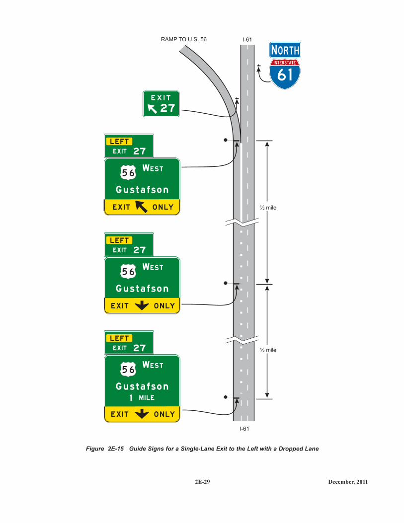
For lane drops, the Exit Direction sign (see Section 2E.36and Figure 2E-26) shall be of the format shown in Figures2E-15 and 2E-16. The bottom portion of the Exit Directionsign shall be yellow with a black border and shall include adiagonally upward-pointing black directional arrow (left orright) for each lane dropped at the exit, with the signdesigned and placed so that each arrow is located over theapproximate center of each lane being dropped. The wordsEXIT and ONLY shall be positioned to the left and right,respectively, of the arrow on the E11-1d sign panel for asingle-lane drop. For a two-lane drop, the words EXITONLY shall be located between the two arrows on the E11-1e sign panel. The number of arrows on the sign shallcorrespond to the number of dropped lanes at the location ofthe sign.
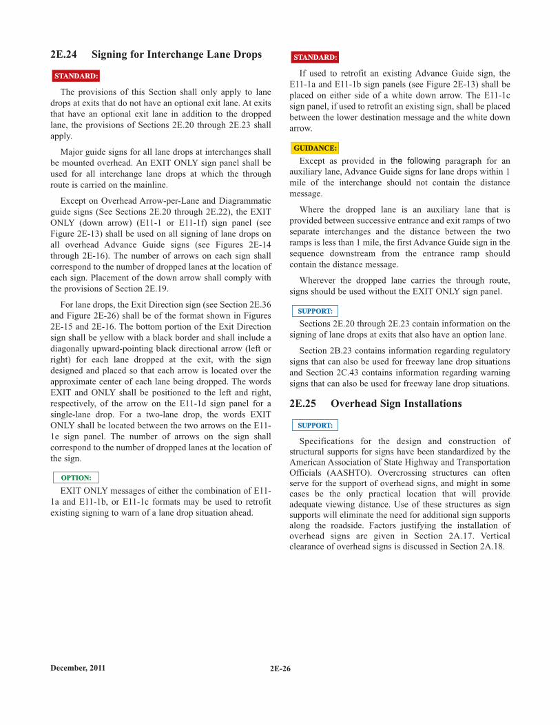
EXIT ONLY messages of either the combination of E11-1a and E11-1b, or E11-1c formats may be used to retrofitexisting signing to warn of a lane drop situation ahead.
OPTION:OPTION:
STANDARD:STANDARD: If used to retrofit an existing Advance Guide sign, theE11-1a and E11-1b sign panels (see Figure 2E-13) shall beplaced on either side of a white down arrow. The E11-1csign panel, if used to retrofit an existing sign, shall be placedbetween the lower destination message and the white downarrow.
Except as provided in the following paragraph for anauxiliary lane, Advance Guide signs for lane drops within 1mile of the interchange should not contain the distancemessage.
Where the dropped lane is an auxiliary lane that isprovided between successive entrance and exit ramps of twoseparate interchanges and the distance between the tworamps is less than 1 mile, the first Advance Guide sign in thesequence downstream from the entrance ramp shouldcontain the distance message.
Wherever the dropped lane carries the through route,signs should be used without the EXIT ONLY sign panel.
Sections 2E.20 through 2E.23 contain information on thesigning of lane drops at exits that also have an option lane.
Section 2B.23 contains information regarding regulatorysigns that can also be used for freeway lane drop situationsand Section 2C.43 contains information regarding warningsigns that can also be used for freeway lane drop situations.
2E.25 Overhead Sign Installations
Specifications for the design and construction ofstructural supports for signs have been standardized by theAmerican Association of State Highway and TransportationOfficials (AASHTO). Overcrossing structures can oftenserve for the support of overhead signs, and might in somecases be the only practical location that will provideadequate viewing distance. Use of these structures as signsupports will eliminate the need for additional sign supportsalong the roadside. Factors justifying the installation ofoverhead signs are given in Section 2A.17. Verticalclearance of overhead signs is discussed in Section 2A.18.
STANDARD:STANDARD:
SUPPORT:SUPPORT:
SUPPORT:SUPPORT:
GUIDANCE:GUIDANCE:
2E.26 Lateral Offset
The minimum lateral offset outside the usable roadwayshoulder for post-mounted freeway and expressway signs orfor overhead sign supports, either to the right-hand or left-hand side of the roadway, shall be 6 feet. This minimumclearance shall also apply outside of a curb. If located withinthe clear zone, the signs shall be mounted on crashworthysupports or shielded by appropriate crashworthy barriers.
Where practical, a sign should not be less than 10 feetfrom the edge of the nearest traffic lane. Large guide signsespecially should be farther removed, preferably 30 feet ormore from the nearest traffic lane.
Where an expressway median is 12 feet or less in width,consideration should be given to spanning both roadwayswithout a center support.
STANDARD:STANDARD:
GUIDANCE:GUIDANCE:
Where overhead sign supports cannot be placed suffi-ciently far away from the line of traffic or in an otherwiseprotected site, they should either be designed to minimizethe impact forces, or be adequately shielded by a trafficbarrier of suitable design.
Butterfly-type sign supports and other overhead non-crashworthy sign supports shall not be installed in gores orother unshielded locations within the clear zone.
Lesser clearances, but not generally less than 6 feet, maybe used on connecting roadways or ramps at interchanges.
STANDARD:STANDARD:
OPTION:OPTION:
2E-27 December, 2011
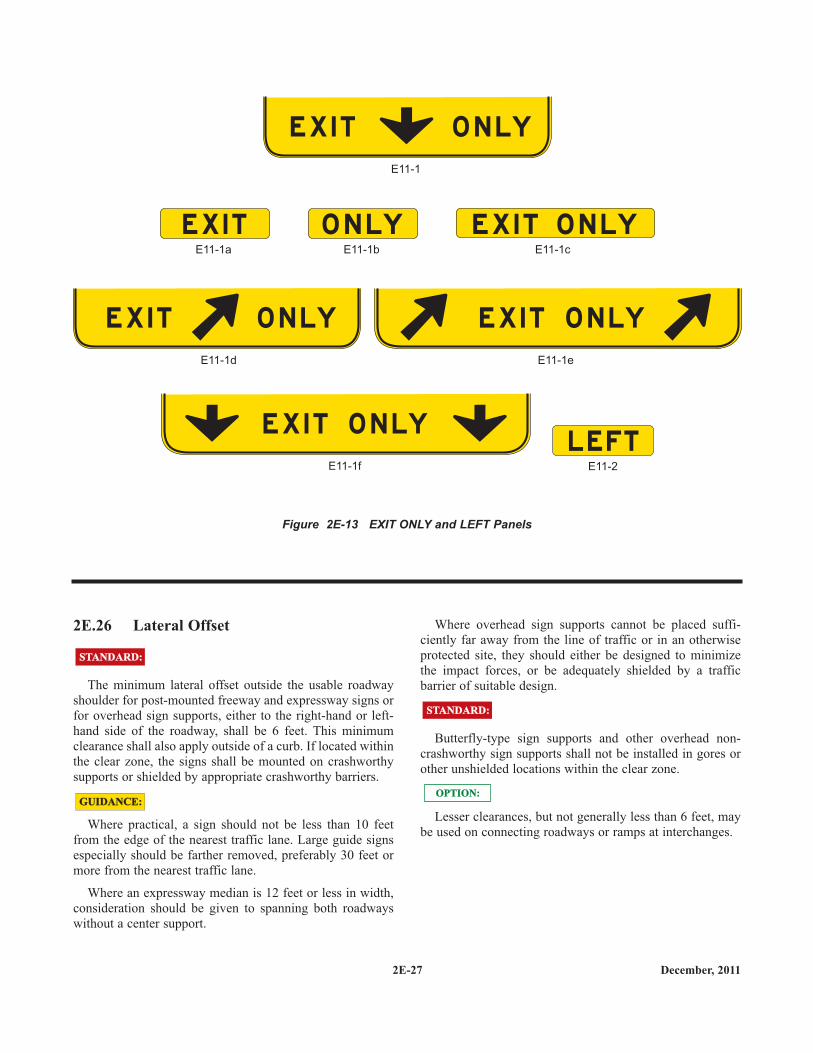
Figure 2E-13 EXIT ONLY and LEFT Panels
E X I T O N LY
E X I T O N LY
O N LY E X I T O N LYE X I T
L E FT
E11-1
E11-1d
E11-1f
E11-1e
E11-1b E11-1cE11-1a
E11-2
E X I T O N LY E X I T O N LY
2E-28December, 2011
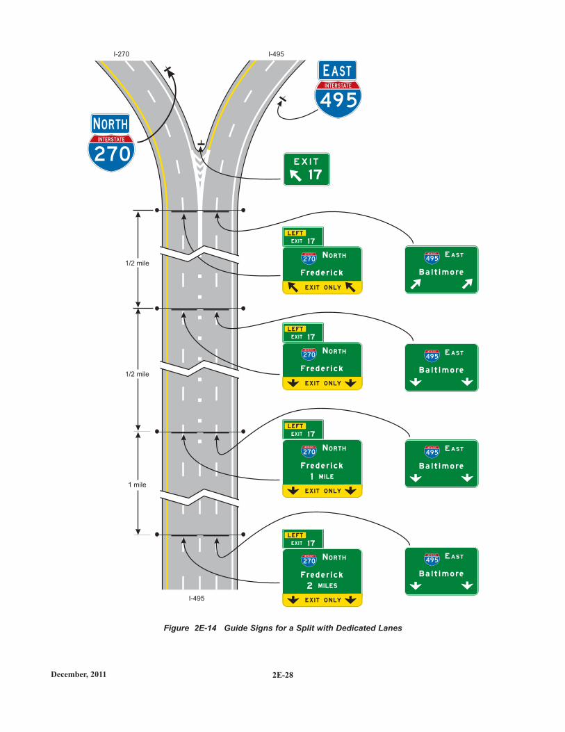
Figure 2E-14 Guide Signs for a Split with Dedicated Lanes
1 7
1 mile
1/2 mile
1/2 mile
I-495I-270
I-495
NN O RTHO RTH
E X I T O N LY
F re d e r i c k
F re d e r i c k
F re d e r i c k
F re d e r i c k
B a l t i m o re
B a l t i m o re
B a l t i m o re
B a l t i m o re
N O R T H
N O R T H
N O R T H
N O R T H
270
INTERSTATE
2 70
INTERSTATE
4 9 5
INTERSTATE
4 9 5
INTERSTATE
4 9 5
INTERSTATE
4 9 5
INTERSTATE
2 7 0
INTERSTATE
2 7 0
INTERSTATE
2 7 0
INTERSTATE
4 9 5
INTERSTATE
EE ASTAST
L E FT
L E FT
L E FT
L E FT
E AS T
E AS T
E AS T
E AS T
E X I T O N LY
E X I T O N LY
E X I T O N LY
M I LE
M I L ES
1
2
EX I T 1 7
EX I T 1 7
EX I T 1 7
EX I T 1 7
2E-29 December, 2011
Figure 2E-15 Guide Signs for a Single-Lane Exit to the Left with a Dropped Lane
6 1
INTERSTATE
27
½ mile
½ mile
I-61
I-61RAMP TO U.S. 56
NN O RTHO RTH
L E FT
EX I T 27
L E FT
EX I T 27
L E FT
EX I T 27
WES T
WES T
WES T
5 6
5 6
5 6
E X I T O N LY
E X I T O N LY
E X I T O N LY
G u s t a f s o n
M I LE1
G u s t a f s o n
G u s t a f s o n
2E-30December, 2011
Figure 2E-16 Guide Signs for a Single-Lane Exit to the Right with a Dropped Lane
3 5
½ mile
½ mile
I-22
I-22 RAMP TO U.S. 46
EX I T 3 5
EX I T 3 5
EX I T 3 5
4 6
4 6
4 6
E X I T O N LY
E X I T O N LY
E X I T O N LY
A n d e rs o n
M I LE1
A n d e rs o n
A n d e rs o n
22
INTERSTATE
WWESTEST
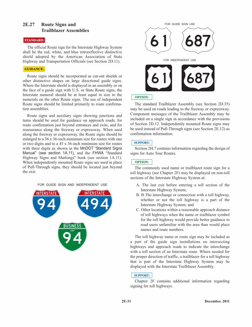
2E.27 Route Signs andTrailblazer Assemblies
The official Route sign for the Interstate Highway Systemshall be the red, white, and blue retroreflective distinctiveshield adopted by the American Association of StateHighway and Transportation Officials (see Section 2D.11).
Route signs should be incorporated as cut-out shields orother distinctive shapes on large directional guide signs.Where the Interstate shield is displayed in an assembly or onthe face of a guide sign with U.S. or State Route signs, theInterstate numeral should be at least equal in size to thenumerals on the other Route signs. The use of independentRoute signs should be limited primarily to route confirma-tion assemblies.
Route signs and auxiliary signs showing junctions andturns should be used for guidance on approach roads, forroute confirmation just beyond entrances and exits, and forreassurance along the freeway or expressway. When usedalong the freeway or expressway, the Route signs should beenlarged to a 36 x 36-inch minimum size for routes with oneor two digits and to a 45 x 36-inch minimum size for routeswith three digits as shown in the MnDOT “Standard SignsManual” (see section 1A.11), and the FHWA "StandardHighway Signs and Markings" book (see section 1A.11).When independently mounted Route signs are used in placeof Pull-Through signs, they should be located just beyondthe exit.
94
INTERSTATE
4 94
INTERSTATE
9 4
BUS I N ESSLOO P
FOR GUIDE SIGN AND INDEPENDENT USE
GUIDANCE:GUIDANCE:
STANDARD:STANDARD:
The standard Trailblazer Assembly (see Section 2D.35)may be used on roads leading to the freeway or expressway.Component messages of the Trailblazer Assembly may beincluded on a single sign in accordance with the provisionsof Section 2D.12. Independently mounted Route signs maybe used instead of Pull-Through signs (see Section 2E.12) asconfirmation information.
Section 2H.7 contains information regarding the design ofsigns for Auto Tour Routes.
The commonly used name or trailblazer route sign for atoll highway (see Chapter 2F) may be displayed on non-tollsections of the Interstate Highway System at:
A. The last exit before entering a toll section of theInterstate Highway System;
B. B.The interchange or connection with a toll highway,whether or not the toll highway is a part of theInterstate Highway System; and
C. Other locations within a reasonable approach distanceof toll highways when the name or trailblazer symbolfor the toll highway would provide better guidance toroad users unfamiliar with the area than would placenames and route numbers.
The toll highway name or route sign may be included asa part of the guide sign installations on intersectinghighways and approach roads to indicate the interchangewith a toll section of an Interstate route. Where needed forthe proper direction of traffic, a trailblazer for a toll highwaythat is part of the Interstate Highway System may bedisplayed with the Interstate Trailblazer Assembly.
Chapter 2F contains additional information regardingsigning for toll highways.
SUPPORT:SUPPORT:
SUPPORT:SUPPORT:
OPTION:OPTION:
OPTION:OPTION:
FOR GUIDE SIGN USE
FOR INDEPENDENT USE
6 1 687
6 1 687
2E-31 December, 2011
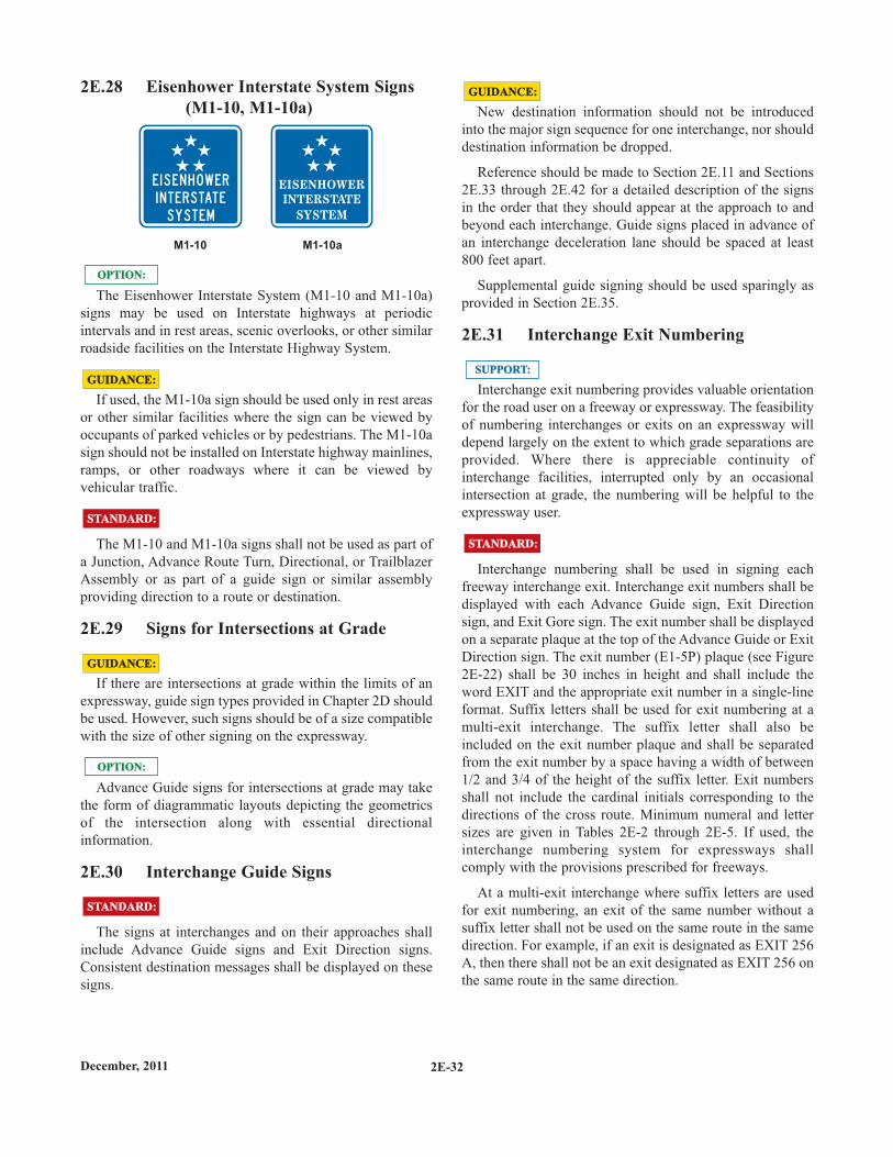
2E.28 Eisenhower Interstate System Signs(M1-10, M1-10a)
The Eisenhower Interstate System (M1-10 and M1-10a)signs may be used on Interstate highways at periodicintervals and in rest areas, scenic overlooks, or other similarroadside facilities on the Interstate Highway System.
If used, the M1-10a sign should be used only in rest areasor other similar facilities where the sign can be viewed byoccupants of parked vehicles or by pedestrians. The M1-10asign should not be installed on Interstate highway mainlines,ramps, or other roadways where it can be viewed byvehicular traffic.
The M1-10 and M1-10a signs shall not be used as part ofa Junction, Advance Route Turn, Directional, or TrailblazerAssembly or as part of a guide sign or similar assemblyproviding direction to a route or destination.
2E.29 Signs for Intersections at Grade
If there are intersections at grade within the limits of anexpressway, guide sign types provided in Chapter 2D shouldbe used. However, such signs should be of a size compatiblewith the size of other signing on the expressway.
Advance Guide signs for intersections at grade may takethe form of diagrammatic layouts depicting the geometricsof the intersection along with essential directionalinformation.
2E.30 Interchange Guide Signs
The signs at interchanges and on their approaches shallinclude Advance Guide signs and Exit Direction signs.Consistent destination messages shall be displayed on thesesigns.
STANDARD:STANDARD:
M1-10aM1-10
E I S E N H OWER
I N T E R S TAT E
SYS T EM
STANDARD:STANDARD:
GUIDANCE:GUIDANCE:
OPTION:OPTION:
OPTION:OPTION:
GUIDANCE:GUIDANCE:
New destination information should not be introducedinto the major sign sequence for one interchange, nor shoulddestination information be dropped.
Reference should be made to Section 2E.11 and Sections2E.33 through 2E.42 for a detailed description of the signsin the order that they should appear at the approach to andbeyond each interchange. Guide signs placed in advance ofan interchange deceleration lane should be spaced at least800 feet apart.
Supplemental guide signing should be used sparingly asprovided in Section 2E.35.
2E.31 Interchange Exit Numbering
Interchange exit numbering provides valuable orientationfor the road user on a freeway or expressway. The feasibilityof numbering interchanges or exits on an expressway willdepend largely on the extent to which grade separations areprovided. Where there is appreciable continuity ofinterchange facilities, interrupted only by an occasionalintersection at grade, the numbering will be helpful to theexpressway user.
Interchange numbering shall be used in signing eachfreeway interchange exit. Interchange exit numbers shall bedisplayed with each Advance Guide sign, Exit Directionsign, and Exit Gore sign. The exit number shall be displayedon a separate plaque at the top of the Advance Guide or ExitDirection sign. The exit number (E1-5P) plaque (see Figure2E-22) shall be 30 inches in height and shall include theword EXIT and the appropriate exit number in a single-lineformat. Suffix letters shall be used for exit numbering at amulti-exit interchange. The suffix letter shall also beincluded on the exit number plaque and shall be separatedfrom the exit number by a space having a width of between1/2 and 3/4 of the height of the suffix letter. Exit numbersshall not include the cardinal initials corresponding to thedirections of the cross route. Minimum numeral and lettersizes are given in Tables 2E-2 through 2E-5. If used, theinterchange numbering system for expressways shallcomply with the provisions prescribed for freeways.
At a multi-exit interchange where suffix letters are usedfor exit numbering, an exit of the same number without asuffix letter shall not be used on the same route in the samedirection. For example, if an exit is designated as EXIT 256A, then there shall not be an exit designated as EXIT 256 onthe same route in the same direction.
GUIDANCE:GUIDANCE:
STANDARD:STANDARD:
SUPPORT:SUPPORT:
2E-32December, 2011
2E-33 December, 2011
Interchange exit numbering shall use the referencelocation sign exit numbering method. The consecutive exitnumbering method shall not be used.
Reference location sign exit numbering assists road usersin determining their destination distances and travelmileage, and assists highway agencies because the exitnumbering sequence does not have to be changed if newinterchanges are added to a route.
Exit numbers may also be used with Supplemental Guidesigns and Motorist Service signs.
Exit number (E1-5P) plaques should be added to the topright-hand edge of the sign for an exit to the right.
Because road users might not expect an exit to the left andmight have difficulty in maneuvering to the left, a left exitnumber (E1-5bP) plaque (see Figure 2E-22) shall be addedto the top left-hand edge of the sign for all left-hand exits(see Figures 2E-14 and 2E-15). The word LEFT on the E1-5bP plaque shall be a black legend on a yellow rectangularsign panel and shall be centered above the word EXIT.
Compliance Date: December 31, 2014
Example exit number plaque designs are shown in Figure2E-22. Figures 2E-3, 2E-7, 2E-22, 2E-26, and 2E-27illustrate the incorporation of exit number plaques on guidesigns.
The general plan for numbering interchange exits isshown in Figures 2E-19 through 2E-21. Figure 2E-19 showsa circumferential route, which is a route that makes acomplete circle around a city or town and usually has twointerchanges (one on each side of the city or town) with eachof the mainline routes that travel through the city or town.Figure 2E-20 shows a loop route, which is a route thatdeparts from a mainline route and then rejoins the samemainline route at a subsequent point downstream, and a spurroute, which is a route that departs from a mainline route andnever rejoins the same mainline route. Figure 2E-21 showstwo mainline routes that overlap each other.
Regardless of whether a mainline route originates withina State or crosses into a State from another State, the south-ernmost or westernmost terminus within that State shall bethe beginning point for interchange numbering.
SUPPORT:SUPPORT:
OPTION:OPTION:
GUIDANCE:GUIDANCE:
STANDARD:STANDARD:
SUPPORT:SUPPORT:
STANDARD:STANDARD:
For circumferential routes, interchange numbering shallbe in a clockwise direction. The numbering shall begin withthe first interchange west of the south end of an imaginarynorth-south line bisecting the circumferential route, at aradial freeway or other Interstate route, or some otherconspicuous landmark in the circumferential route near asouth polar location (see Figure 2E-19).
The interchange numbers on loop routes shall begin at theloop interchange nearest the south or west mainline junctionand increase in magnitude toward the north or east mainlinejunction (see Figure 2E-20).
Spur route interchanges shall be numbered in ascendingorder starting at the interchange where the spur leaves themainline route (see Figure 2E-20).
If a circumferential, loop, or spur route crosses Stateboundaries, the numbering sequence shall be coordinated bythe States to provide continuous interchange numbering.
Where numbered routes overlap, continuity ofinterchange numbering shall be established for only one ofthe routes (see Figure 2E-21). If one of the routes is anInterstate and the other route is not an Interstate, theInterstate route shall maintain continuity of interchangenumbering.
The route chosen for continuity of interchange numberingshould also have reference location sign continuity (seeFigure 2E-21).
2E.32 Interchange Classification
For signing purposes, interchanges are classified asmajor, intermediate, and minor. The minimum alphabet sizescontained in Tables 2E-2 and 2E-4 are based on this classi-fication. Descriptions of these classifications are as follows:
A. Major interchanges are subdivided into twocategories: (a) interchanges with other expressways orfreeways, or (b) interchanges with high-volume multi-lane highways, principal urban arterials, and majorrural routes where the volume of interchanging trafficis heavy or includes many road users unfamiliar withthe area.
B. Intermediate interchanges are those with urban andrural routes not in the category of major or minorinterchanges.
C. Minor interchanges include those where traffic islocal and very light, such as interchanges with landservice access roads. Where the sum of exit volumesis estimated to be lower than 100 vehicles per day inthe design year, the interchange is classified as minor.
GUIDANCE:GUIDANCE:
SUPPORT:SUPPORT:
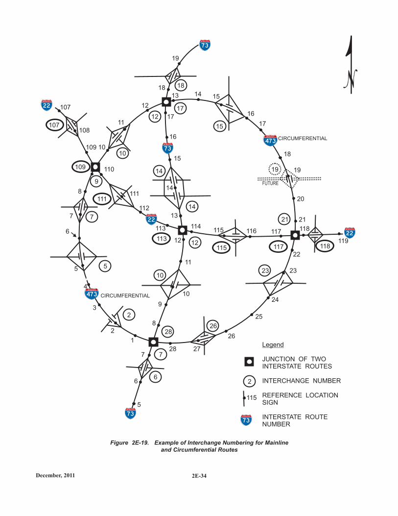
2E-34December, 2011
Figure 2E-19. Example of Interchange Numbering for Mainlineand Circumferential Routes
US 39
18
19
15
16
16
107
108
109
110
8
112
113
11
9
10
6
3
2
1
4
8
7
6
7
5
116 117115114
20
19
18
21
25
24
26
2728
23
22
119
118
5
111
10
11
15
12
13 14
14
13
12
17
18
17
CIRCUMFERENTIAL
CIRCUMFERENTIAL
Legend
JUNCTION OF TWOINTERSTATE ROUTES
INTERCHANGE NUMBER
REFERENCE LOCATIONSIGN
INTERSTATE ROUTENUMBER
12
10
14
14
9
7
12
10
2826
23
21
19
2
7
62
5
107
109
111
113
115 117 118
FUTURE
115
15
17
73
INTERSTATE
7 3
INTERSTATE
2 2
INTERSTATE
2 2
INTERSTATE
2 2
INTERSTATE
7 3
INTERSTATE
7 3
INTERSTATE
47 3
INTERSTATE
47 3
INTERSTATE
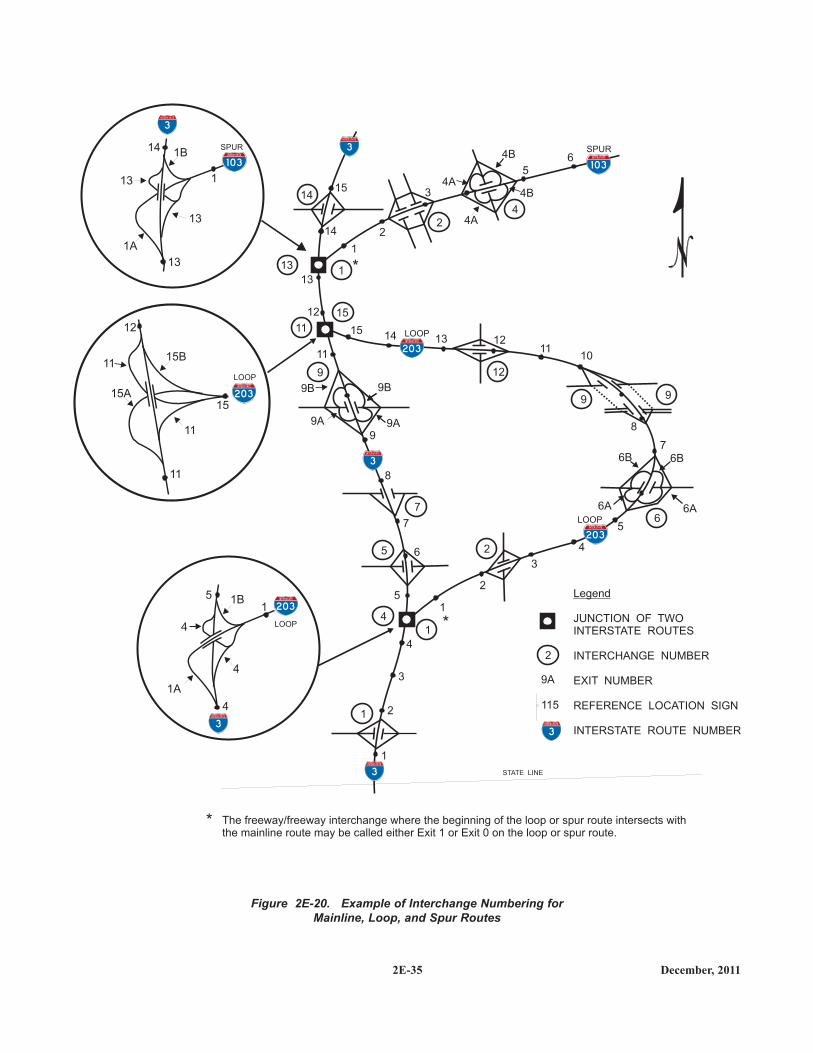
2E-35 December, 2011
Figure 2E-20. Example of Interchange Numbering forMainline, Loop, and Spur Routes
15
14 2
1
*
*
*
1415
13
11
12
13
1011
12
5
4
3
2
1
8
7
6
9
5
7
8
4
3
2
1
6A
6B 6B
6A
9A
9B 9B
9A
65
3
LOOP
LOOP
SPUR
4A
4B
4B
4A
14
13
15
1
11
9
6
9
7
5
4
1
1
9 12
4
2
2
9A
115
The freeway/freeway interchange where the beginning of the loop or spur route intersects withthe mainline route may be called either Exit 1 or Exit 0 on the loop or spur route.
Legend
JUNCTION OF TWOINTERSTATE ROUTES
INTERCHANGE NUMBER
EXIT NUMBER
REFERENCE LOCATION SIGN
INTERSTATE ROUTE NUMBER
2
STATE LINE
1A
4
4
4
5 1B1
LOOP
1A
1B
1
14
13
13
13
SPUR
11
12
15B
15A
11
11
15
LOOP
1 0 3
INTERSTATE
1 0 3
INTERSTATE
2 0 3
INTERSTATE
2 0 3
INTERSTATE
2 0 3
INTERSTATE
2 0 3
INTERSTATE
3
INTERSTATE
3
INTERSTATE
3
INTERSTATE
3
INTERSTATE3
INTERSTATE
3
INTERSTATE
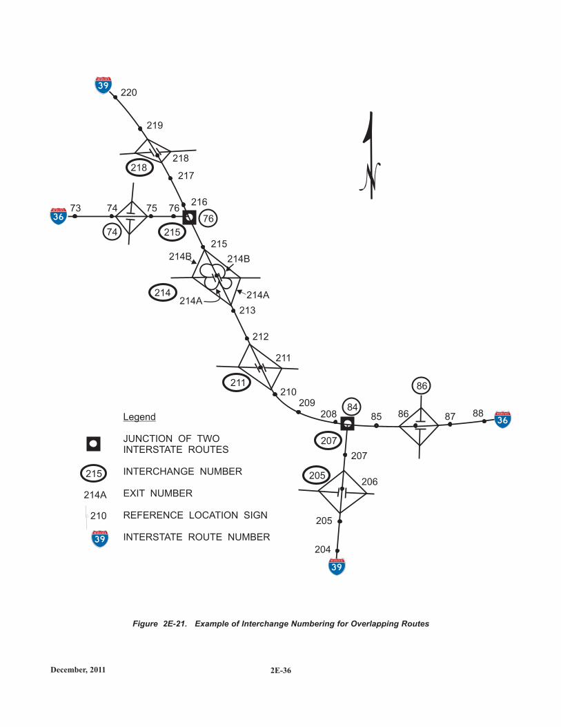
2E-36December, 2011
Figure 2E-21. Example of Interchange Numbering for Overlapping Routes
220
219
218
217
21675 767473
215
210209
208
207
206
204
211
212
213
85 86 87 88
205
214B 214B
214A214A
86
84
76
74
218
215
214
211
207
205
214A
210
Legend
JUNCTION OF TWOINTERSTATE ROUTES
INTERCHANGE NUMBER
EXIT NUMBER
REFERENCE LOCATION SIGN
INTERSTATE ROUTE NUMBER
215
36
INTERSTATE
3 6
INTERSTATE
3 9
INTERSTATE
3 9
INTERSTATE
3 9
INTERSTATE
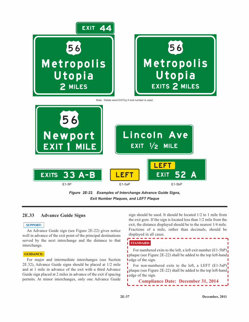
2E.33 Advance Guide Signs
An Advance Guide sign (see Figure 2E-22) gives noticewell in advance of the exit point of the principal destinationsserved by the next interchange and the distance to thatinterchange.
For major and intermediate interchanges (see Section2E.32), Advance Guide signs should be placed at 1/2 mileand at 1 mile in advance of the exit with a third AdvanceGuide sign placed at 2 miles in advance of the exit if spacingpermits. At minor interchanges, only one Advance Guide
SUPPORT:SUPPORT:
GUIDANCE:GUIDANCE:
sign should be used. It should be located 1/2 to 1 mile fromthe exit gore. If the sign is located less than 1/2 mile from theexit, the distance displayed should be to the nearest 1/4 mile.Fractions of a mile, rather than decimals, should bedisplayed in all cases.
For numbered exits to the left, a left exit number (E1-5bP)plaque (see Figure 2E-22) shall be added to the top left-handedge of the sign.
For non-numbered exits to the left, a LEFT (E1-5aP)plaque (see Figure 2E-22) shall be added to the top left-handedge of the sign.
Compliance Date: December 31, 2014
STANDARD:STANDARD:
2E-37 December, 2011
Figure 2E-22. Examples of Interchange Advance Guide Signs,Exit Number Plaques, and LEFT Plaque
E1-5bPE1-5aPE1-5P
Note: Delete word EXIT(s) if exit number is used.
M e t ro p o l i sU t o p i a
M I LES2
5 6
M e t ro p o l i sU t o p i a
M I LESEX I TS 2
5 6
EX I T 44
N ew p o rt1 M I L EEX I T
5 6
L i n c o l n Ave
M I LEEX I T 1 2
EX I TS 3 3 A- B L E FT
L E FT
E X I T 5 2 A
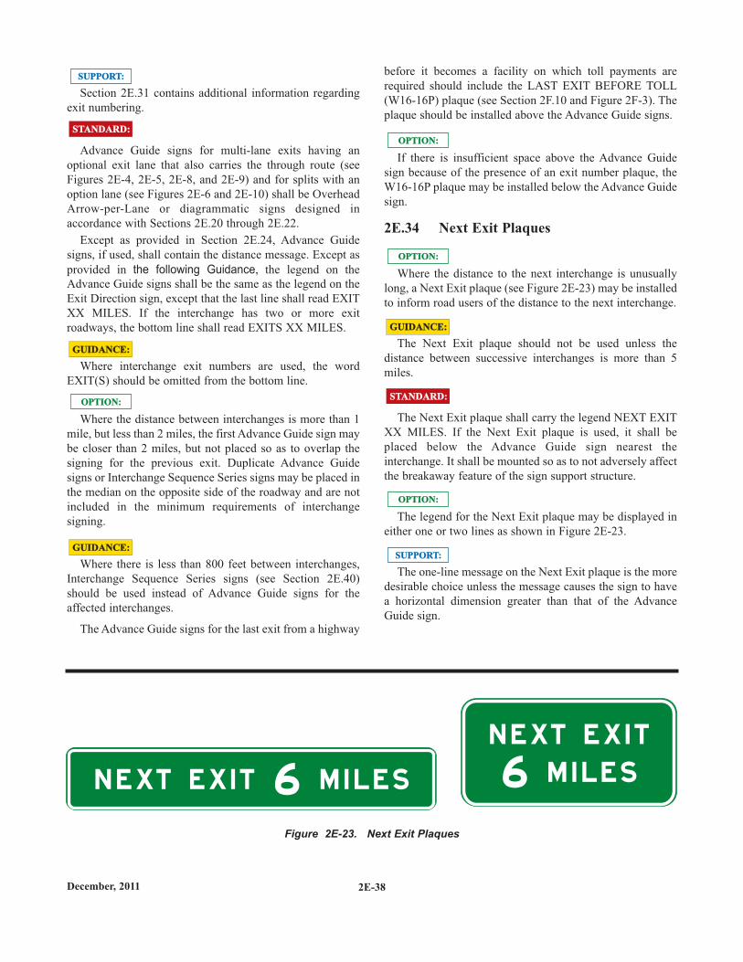
2E-38December, 2011
Section 2E.31 contains additional information regardingexit numbering.
Advance Guide signs for multi-lane exits having anoptional exit lane that also carries the through route (seeFigures 2E-4, 2E-5, 2E-8, and 2E-9) and for splits with anoption lane (see Figures 2E-6 and 2E-10) shall be OverheadArrow-per-Lane or diagrammatic signs designed inaccordance with Sections 2E.20 through 2E.22.
Except as provided in Section 2E.24, Advance Guidesigns, if used, shall contain the distance message. Except asprovided in the following Guidance, the legend on theAdvance Guide signs shall be the same as the legend on theExit Direction sign, except that the last line shall read EXITXX MILES. If the interchange has two or more exitroadways, the bottom line shall read EXITS XX MILES.
Where interchange exit numbers are used, the wordEXIT(S) should be omitted from the bottom line.
Where the distance between interchanges is more than 1mile, but less than 2 miles, the first Advance Guide sign maybe closer than 2 miles, but not placed so as to overlap thesigning for the previous exit. Duplicate Advance Guidesigns or Interchange Sequence Series signs may be placed inthe median on the opposite side of the roadway and are notincluded in the minimum requirements of interchangesigning.
Where there is less than 800 feet between interchanges,Interchange Sequence Series signs (see Section 2E.40)should be used instead of Advance Guide signs for theaffected interchanges.
The Advance Guide signs for the last exit from a highway
OPTION:OPTION:
GUIDANCE:GUIDANCE:
SUPPORT:SUPPORT:
STANDARD:STANDARD:
GUIDANCE:GUIDANCE:
N E XT E X I T
N E XT E X I T
M I L E S M I L E S6 6
Figure 2E-23. Next Exit Plaques
before it becomes a facility on which toll payments arerequired should include the LAST EXIT BEFORE TOLL(W16-16P) plaque (see Section 2F.10 and Figure 2F-3). Theplaque should be installed above the Advance Guide signs.
If there is insufficient space above the Advance Guidesign because of the presence of an exit number plaque, theW16-16P plaque may be installed below the Advance Guidesign.
2E.34 Next Exit Plaques
Where the distance to the next interchange is unusuallylong, a Next Exit plaque (see Figure 2E-23) may be installedto inform road users of the distance to the next interchange.
The Next Exit plaque should not be used unless thedistance between successive interchanges is more than 5miles.
The Next Exit plaque shall carry the legend NEXT EXITXX MILES. If the Next Exit plaque is used, it shall beplaced below the Advance Guide sign nearest theinterchange. It shall be mounted so as to not adversely affectthe breakaway feature of the sign support structure.
The legend for the Next Exit plaque may be displayed ineither one or two lines as shown in Figure 2E-23.
The one-line message on the Next Exit plaque is the moredesirable choice unless the message causes the sign to havea horizontal dimension greater than that of the AdvanceGuide sign.
OPTION:OPTION:
OPTION:OPTION:
OPTION:OPTION:
GUIDANCE:GUIDANCE:
STANDARD:STANDARD:
SUPPORT:SUPPORT:
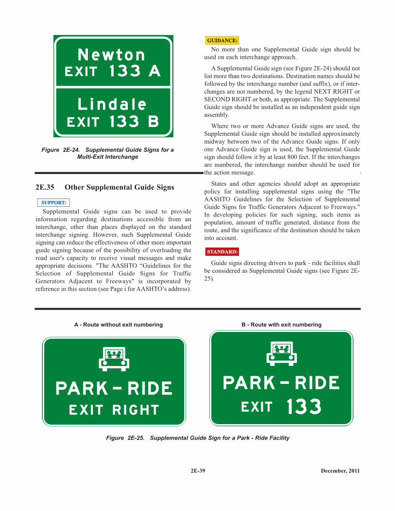
2E-39 December, 2011
2E.35 Other Supplemental Guide Signs
Supplemental Guide signs can be used to provideinformation regarding destinations accessible from aninterchange, other than places displayed on the standardinterchange signing. However, such Supplemental Guidesigning can reduce the effectiveness of other more importantguide signing because of the possibility of overloading theroad user's capacity to receive visual messages and makeappropriate decisions. "The AASHTO “Guidelines for theSelection of Supplemental Guide Signs for TrafficGenerators Adjacent to Freeways" is incorporated byreference in this section (see Page i for AASHTO’s address).
SUPPORT:SUPPORT:
No more than one Supplemental Guide sign should beused on each interchange approach.
A Supplemental Guide sign (see Figure 2E-24) should notlist more than two destinations. Destination names should befollowed by the interchange number (and suffix), or if inter-changes are not numbered, by the legend NEXT RIGHT orSECOND RIGHT or both, as appropriate. The SupplementalGuide sign should be installed as an independent guide signassembly.
Where two or more Advance Guide signs are used, theSupplemental Guide sign should be installed approximatelymidway between two of the Advance Guide signs. If onlyone Advance Guide sign is used, the Supplemental Guidesign should follow it by at least 800 feet. If the interchangesare numbered, the interchange number should be used forthe action message.
States and other agencies should adopt an appropriatepolicy for installing supplemental signs using the "TheAASHTO Guidelines for the Selection of SupplementalGuide Signs for Traffic Generators Adjacent to Freeways."In developing policies for such signing, such items aspopulation, amount of traffic generated, distance from theroute, and the significance of the destination should be takeninto account.
Guide signs directing drivers to park - ride facilities shallbe considered as Supplemental Guide signs (see Figure 2E-25).
GUIDANCE:GUIDANCE:
STANDARD:STANDARD:
N ewt o n
EX I T 1 3 3 A
EX I T 1 33 B
L i n d a l e
Figure 2E-24. Supplemental Guide Signs for aMulti-Exit Interchange
PAR K - R I D E
E X I T R I G H T
PAR K - R I D E
EX I T 1 3 3
B - Route with exit numberingA - Route without exit numbering
Figure 2E-25. Supplemental Guide Sign for a Park - Ride Facility
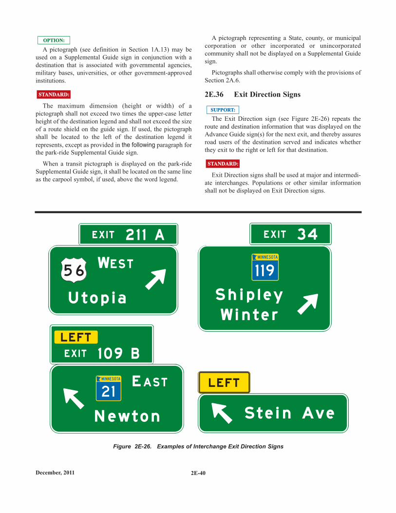
2E-40December, 2011
A pictograph (see definition in Section 1A.13) may beused on a Supplemental Guide sign in conjunction with adestination that is associated with governmental agencies,military bases, universities, or other government-approvedinstitutions.
The maximum dimension (height or width) of apictograph shall not exceed two times the upper-case letterheight of the destination legend and shall not exceed the sizeof a route shield on the guide sign. If used, the pictographshall be located to the left of the destination legend itrepresents, except as provided in the following paragraph forthe park-ride Supplemental Guide sign.
When a transit pictograph is displayed on the park-rideSupplemental Guide sign, it shall be located on the same lineas the carpool symbol, if used, above the word legend.
OPTION:OPTION:
STANDARD:STANDARD:
A pictograph representing a State, county, or municipalcorporation or other incorporated or unincorporatedcommunity shall not be displayed on a Supplemental Guidesign.
Pictographs shall otherwise comply with the provisions ofSection 2A.6.
2E.36 Exit Direction Signs
The Exit Direction sign (see Figure 2E-26) repeats theroute and destination information that was displayed on theAdvance Guide sign(s) for the next exit, and thereby assuresroad users of the destination served and indicates whetherthey exit to the right or left for that destination.
Exit Direction signs shall be used at major and intermedi-ate interchanges. Populations or other similar informationshall not be displayed on Exit Direction signs.
STANDARD:STANDARD:
SUPPORT:SUPPORT:
5 6W
E
U t o p i a
N ewt o n S t e i n Ave
E S T
A S T
E X I T
E X I T
E X I T2 1 1 A
1 0 9 B
3 4
1 1 9
2 1
S h i p l e y
W i n t e r
L E FT
L E FT
Figure 2E-26. Examples of Interchange Exit Direction Signs
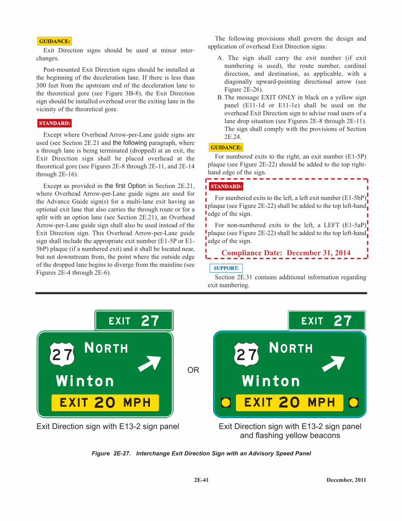
Exit Direction signs should be used at minor inter-changes.
Post-mounted Exit Direction signs should be installed atthe beginning of the deceleration lane. If there is less than300 feet from the upstream end of the deceleration lane tothe theoretical gore (see Figure 3B-8), the Exit Directionsign should be installed overhead over the exiting lane in thevicinity of the theoretical gore.
Except where Overhead Arrow-per-Lane guide signs areused (see Section 2E.21 and the following paragraph, wherea through lane is being terminated (dropped) at an exit, theExit Direction sign shall be placed overhead at thetheoretical gore (see Figures 2E-8 through 2E-11, and 2E-14through 2E-16).
Except as provided in the first Option in Section 2E.21,where Overhead Arrow-per-Lane guide signs are used forthe Advance Guide sign(s) for a multi-lane exit having anoptional exit lane that also carries the through route or for asplit with an option lane (see Section 2E.21), an OverheadArrow-per-Lane guide sign shall also be used instead of theExit Direction sign. This Overhead Arrow-per-Lane guidesign shall include the appropriate exit number (E1-5P or E1-5bP) plaque (if a numbered exit) and it shall be located near,but not downstream from, the point where the outside edgeof the dropped lane begins to diverge from the mainline (seeFigures 2E-4 through 2E-6).
GUIDANCE:GUIDANCE:
STANDARD:STANDARD:
The following provisions shall govern the design andapplication of overhead Exit Direction signs:
A. The sign shall carry the exit number (if exitnumbering is used), the route number, cardinaldirection, and destination, as applicable, with adiagonally upward-pointing directional arrow (seeFigure 2E-26).
B. The message EXIT ONLY in black on a yellow signpanel (E11-1d or E11-1e) shall be used on theoverhead Exit Direction sign to advise road users of alane drop situation (see Figures 2E-8 through 2E-11).The sign shall comply with the provisions of Section2E.24.
For numbered exits to the right, an exit number (E1-5P)plaque (see Figure 2E-22) should be added to the top right-hand edge of the sign.
For numbered exits to the left, a left exit number (E1-5bP)plaque (see Figure 2E-22) shall be added to the top left-handedge of the sign.
For non-numbered exits to the left, a LEFT (E1-5aP)plaque (see Figure 2E-22) shall be added to the top left-handedge of the sign.
Compliance Date: December 31, 2014
Section 2E.31 contains additional information regardingexit numbering.
GUIDANCE:GUIDANCE:
STANDARD:STANDARD:
SUPPORT:SUPPORT:
2E-41 December, 2011
2 7 2 7N N
W i n t o n W i n t o n
O R T H O R T H
M P HE X I T 2 0M P HE X I T 2 0
EX I T E X I T2 7 2 7
Exit Direction sign with E13-2 sign panel Exit Direction sign with E13-2 sign paneland flashing yellow beacons
OR
Figure 2E-27. Interchange Exit Direction Sign with an Advisory Speed Panel
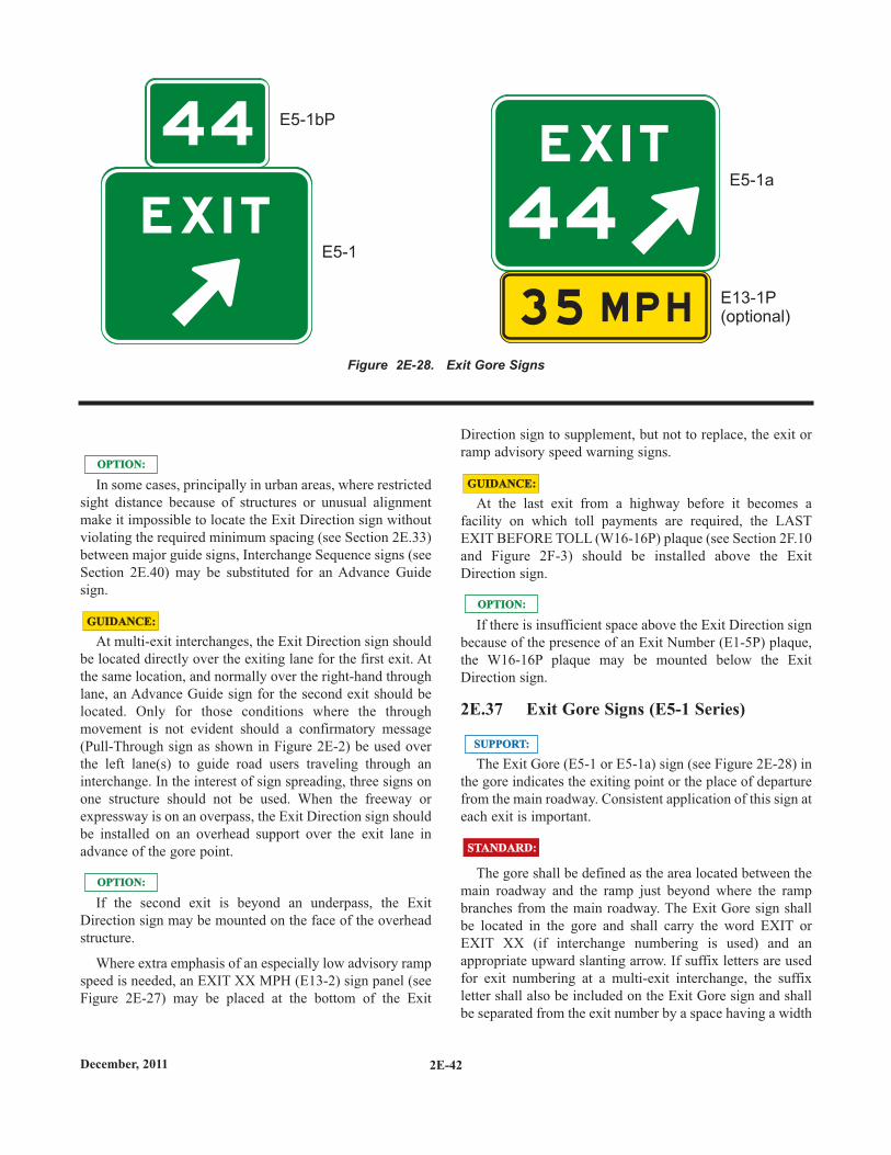
2E-42December, 2011
In some cases, principally in urban areas, where restrictedsight distance because of structures or unusual alignmentmake it impossible to locate the Exit Direction sign withoutviolating the required minimum spacing (see Section 2E.33)between major guide signs, Interchange Sequence signs (seeSection 2E.40) may be substituted for an Advance Guidesign.
At multi-exit interchanges, the Exit Direction sign shouldbe located directly over the exiting lane for the first exit. Atthe same location, and normally over the right-hand throughlane, an Advance Guide sign for the second exit should belocated. Only for those conditions where the throughmovement is not evident should a confirmatory message(Pull-Through sign as shown in Figure 2E-2) be used overthe left lane(s) to guide road users traveling through aninterchange. In the interest of sign spreading, three signs onone structure should not be used. When the freeway orexpressway is on an overpass, the Exit Direction sign shouldbe installed on an overhead support over the exit lane inadvance of the gore point.
If the second exit is beyond an underpass, the ExitDirection sign may be mounted on the face of the overheadstructure.
Where extra emphasis of an especially low advisory rampspeed is needed, an EXIT XX MPH (E13-2) sign panel (seeFigure 2E-27) may be placed at the bottom of the Exit
OPTION:OPTION:
GUIDANCE:GUIDANCE:
OPTION:OPTION:
Direction sign to supplement, but not to replace, the exit orramp advisory speed warning signs.
At the last exit from a highway before it becomes afacility on which toll payments are required, the LASTEXIT BEFORE TOLL (W16-16P) plaque (see Section 2F.10and Figure 2F-3) should be installed above the ExitDirection sign.
If there is insufficient space above the Exit Direction signbecause of the presence of an Exit Number (E1-5P) plaque,the W16-16P plaque may be mounted below the ExitDirection sign.
2E.37 Exit Gore Signs (E5-1 Series)
The Exit Gore (E5-1 or E5-1a) sign (see Figure 2E-28) inthe gore indicates the exiting point or the place of departurefrom the main roadway. Consistent application of this sign ateach exit is important.
The gore shall be defined as the area located between themain roadway and the ramp just beyond where the rampbranches from the main roadway. The Exit Gore sign shallbe located in the gore and shall carry the word EXIT orEXIT XX (if interchange numbering is used) and anappropriate upward slanting arrow. If suffix letters are usedfor exit numbering at a multi-exit interchange, the suffixletter shall also be included on the Exit Gore sign and shallbe separated from the exit number by a space having a width
OPTION:OPTION:
GUIDANCE:GUIDANCE:
SUPPORT:SUPPORT:
STANDARD:STANDARD:
E X I T
E X I T
44
44
M P H3 5
E5-1bP
E5-1
E5-1a
E13-1P(optional)
Figure 2E-28. Exit Gore Signs
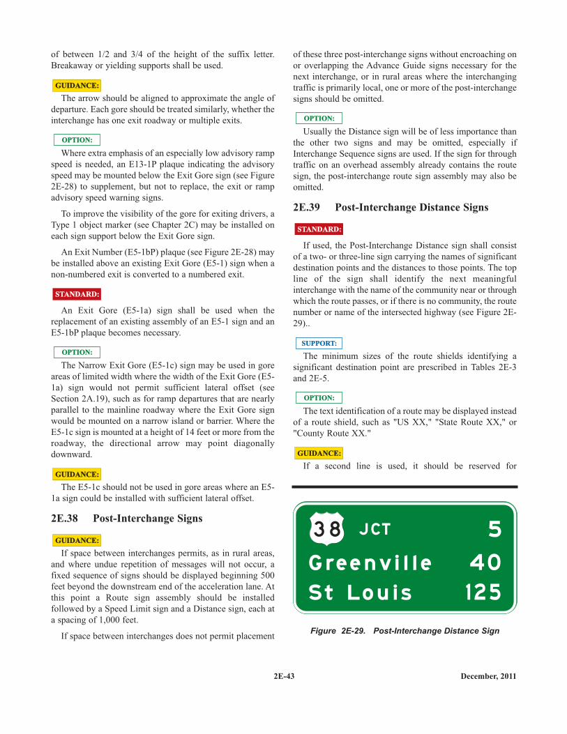
2E-43 December, 2011
of between 1/2 and 3/4 of the height of the suffix letter.Breakaway or yielding supports shall be used.
The arrow should be aligned to approximate the angle ofdeparture. Each gore should be treated similarly, whether theinterchange has one exit roadway or multiple exits.
Where extra emphasis of an especially low advisory rampspeed is needed, an E13-1P plaque indicating the advisoryspeed may be mounted below the Exit Gore sign (see Figure2E-28) to supplement, but not to replace, the exit or rampadvisory speed warning signs.
To improve the visibility of the gore for exiting drivers, aType 1 object marker (see Chapter 2C) may be installed oneach sign support below the Exit Gore sign.
An Exit Number (E5-1bP) plaque (see Figure 2E-28) maybe installed above an existing Exit Gore (E5-1) sign when anon-numbered exit is converted to a numbered exit.
An Exit Gore (E5-1a) sign shall be used when thereplacement of an existing assembly of an E5-1 sign and anE5-1bP plaque becomes necessary.
The Narrow Exit Gore (E5-1c) sign may be used in goreareas of limited width where the width of the Exit Gore (E5-1a) sign would not permit sufficient lateral offset (seeSection 2A.19), such as for ramp departures that are nearlyparallel to the mainline roadway where the Exit Gore signwould be mounted on a narrow island or barrier. Where theE5-1c sign is mounted at a height of 14 feet or more from theroadway, the directional arrow may point diagonallydownward.
The E5-1c should not be used in gore areas where an E5-1a sign could be installed with sufficient lateral offset.
2E.38 Post-Interchange Signs
If space between interchanges permits, as in rural areas,and where undue repetition of messages will not occur, afixed sequence of signs should be displayed beginning 500feet beyond the downstream end of the acceleration lane. Atthis point a Route sign assembly should be installedfollowed by a Speed Limit sign and a Distance sign, each ata spacing of 1,000 feet.
If space between interchanges does not permit placement
GUIDANCE:GUIDANCE:
GUIDANCE:GUIDANCE:
OPTION:OPTION:
STANDARD:STANDARD:
GUIDANCE:GUIDANCE:
OPTION:OPTION:
of these three post-interchange signs without encroaching onor overlapping the Advance Guide signs necessary for thenext interchange, or in rural areas where the interchangingtraffic is primarily local, one or more of the post-interchangesigns should be omitted.
Usually the Distance sign will be of less importance thanthe other two signs and may be omitted, especially ifInterchange Sequence signs are used. If the sign for throughtraffic on an overhead assembly already contains the routesign, the post-interchange route sign assembly may also beomitted.
2E.39 Post-Interchange Distance Signs
If used, the Post-Interchange Distance sign shall consistof a two- or three-line sign carrying the names of significantdestination points and the distances to those points. The topline of the sign shall identify the next meaningfulinterchange with the name of the community near or throughwhich the route passes, or if there is no community, the routenumber or name of the intersected highway (see Figure 2E-29)..
The minimum sizes of the route shields identifying asignificant destination point are prescribed in Tables 2E-3and 2E-5.
The text identification of a route may be displayed insteadof a route shield, such as "US XX," "State Route XX," or"County Route XX."
If a second line is used, it should be reserved forGUIDANCE:GUIDANCE:
OPTION:OPTION:
OPTION:OPTION:
STANDARD:STANDARD:
SUPPORT:SUPPORT:
3 8 J CT
G re e n v i l l e
S t Lo u i s 1 2 5
4 0
5
Figure 2E-29. Post-Interchange Distance Sign
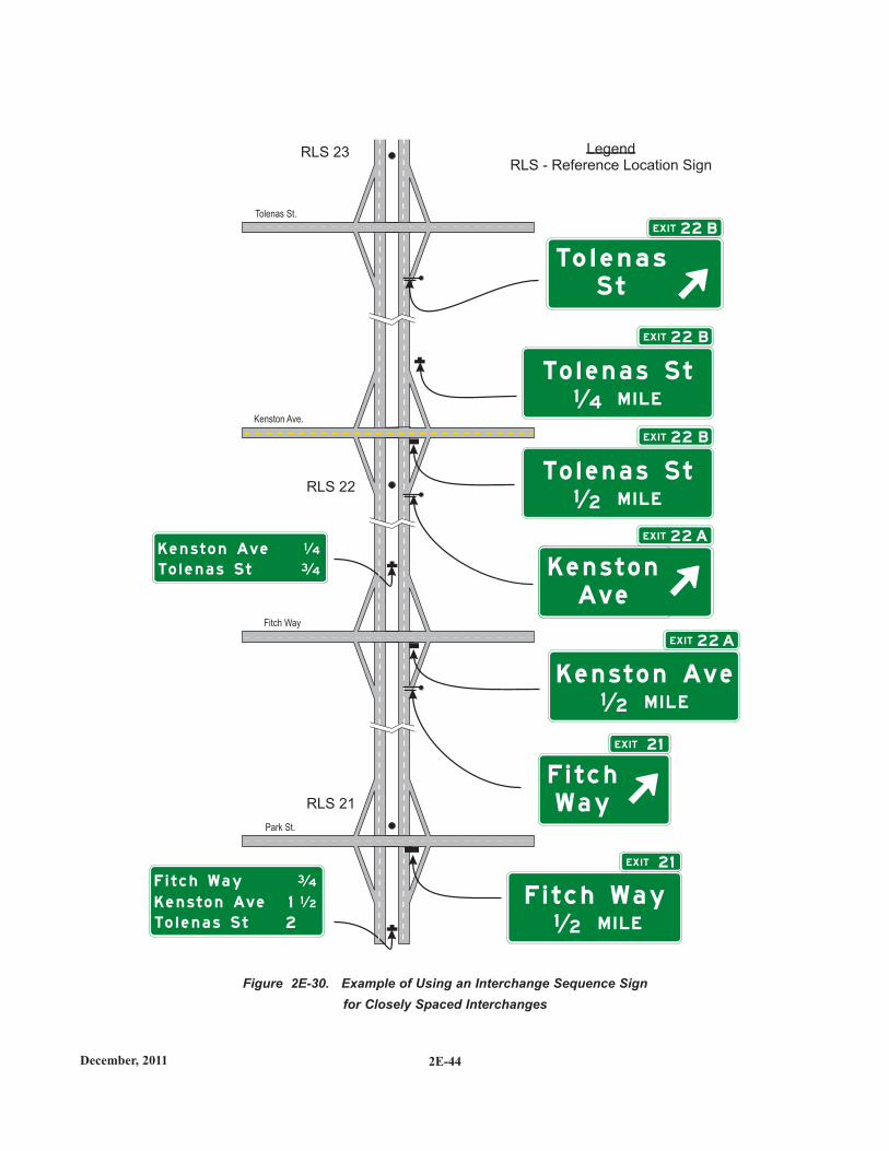
2E-44December, 2011
Figure 2E-30. Example of Using an Interchange Sequence Signfor Closely Spaced Interchanges
RLS 23
RLS 22
RLS 21
LegendRLS - Reference Location Sign
Tolenas St.
Kenston Ave.
Fitch Way
Park St.
F i t c h Wa y
Ke n s t o n Ave
2
1 1 2
To l e n a s S t
3 4
Ke n s t o n Ave 1
To l e n a s S t
4
3 4
F i t c h Wa y
F i t c hW a y
1 2 M I L E
K e n s t o n Ave1 2 M I L E
To l e n a s S t1 2 M I L E
To l e n a s S t1 4 M I L E
K e n s t o nAve
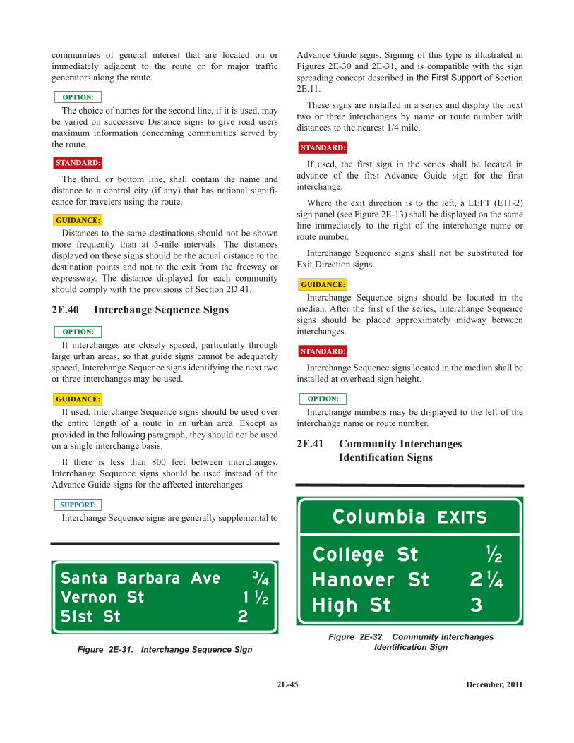
2E-45 December, 2011
communities of general interest that are located on orimmediately adjacent to the route or for major trafficgenerators along the route.
The choice of names for the second line, if it is used, maybe varied on successive Distance signs to give road usersmaximum information concerning communities served bythe route.
The third, or bottom line, shall contain the name anddistance to a control city (if any) that has national signifi-cance for travelers using the route.
Distances to the same destinations should not be shownmore frequently than at 5-mile intervals. The distancesdisplayed on these signs should be the actual distance to thedestination points and not to the exit from the freeway orexpressway. The distance displayed for each communityshould comply with the provisions of Section 2D.41.
2E.40 Interchange Sequence Signs
If interchanges are closely spaced, particularly throughlarge urban areas, so that guide signs cannot be adequatelyspaced, Interchange Sequence signs identifying the next twoor three interchanges may be used.
If used, Interchange Sequence signs should be used overthe entire length of a route in an urban area. Except asprovided in the following paragraph, they should not be usedon a single interchange basis.
If there is less than 800 feet between interchanges,Interchange Sequence signs should be used instead of theAdvance Guide signs for the affected interchanges.
Interchange Sequence signs are generally supplemental toSUPPORT:SUPPORT:
GUIDANCE:GUIDANCE:
OPTION:OPTION:
OPTION:OPTION:
GUIDANCE:GUIDANCE:
STANDARD:STANDARD:
Advance Guide signs. Signing of this type is illustrated inFigures 2E-30 and 2E-31, and is compatible with the signspreading concept described in the First Support of Section2E.11.
These signs are installed in a series and display the nexttwo or three interchanges by name or route number withdistances to the nearest 1/4 mile.
If used, the first sign in the series shall be located inadvance of the first Advance Guide sign for the firstinterchange.
Where the exit direction is to the left, a LEFT (E11-2)sign panel (see Figure 2E-13) shall be displayed on the sameline immediately to the right of the interchange name orroute number.
Interchange Sequence signs shall not be substituted forExit Direction signs.
Interchange Sequence signs should be located in themedian. After the first of the series, Interchange Sequencesigns should be placed approximately midway betweeninterchanges.
Interchange Sequence signs located in the median shall beinstalled at overhead sign height.
Interchange numbers may be displayed to the left of theinterchange name or route number.
2E.41 Community InterchangesIdentification Signs
OPTION:OPTION:
STANDARD:STANDARD:
GUIDANCE:GUIDANCE:
STANDARD:STANDARD:
Sa n ta Ba rba ra Ave 3
1
4
2Ve rn o n St 1
5 1 st St 2
Figure 2E-31. Interchange Sequence Sign
Co l l eg e St
Co l u m b i a EX ITS
H a n ove r St
H i g h St 3
12
142
Figure 2E-32. Community InterchangesIdentification Sign
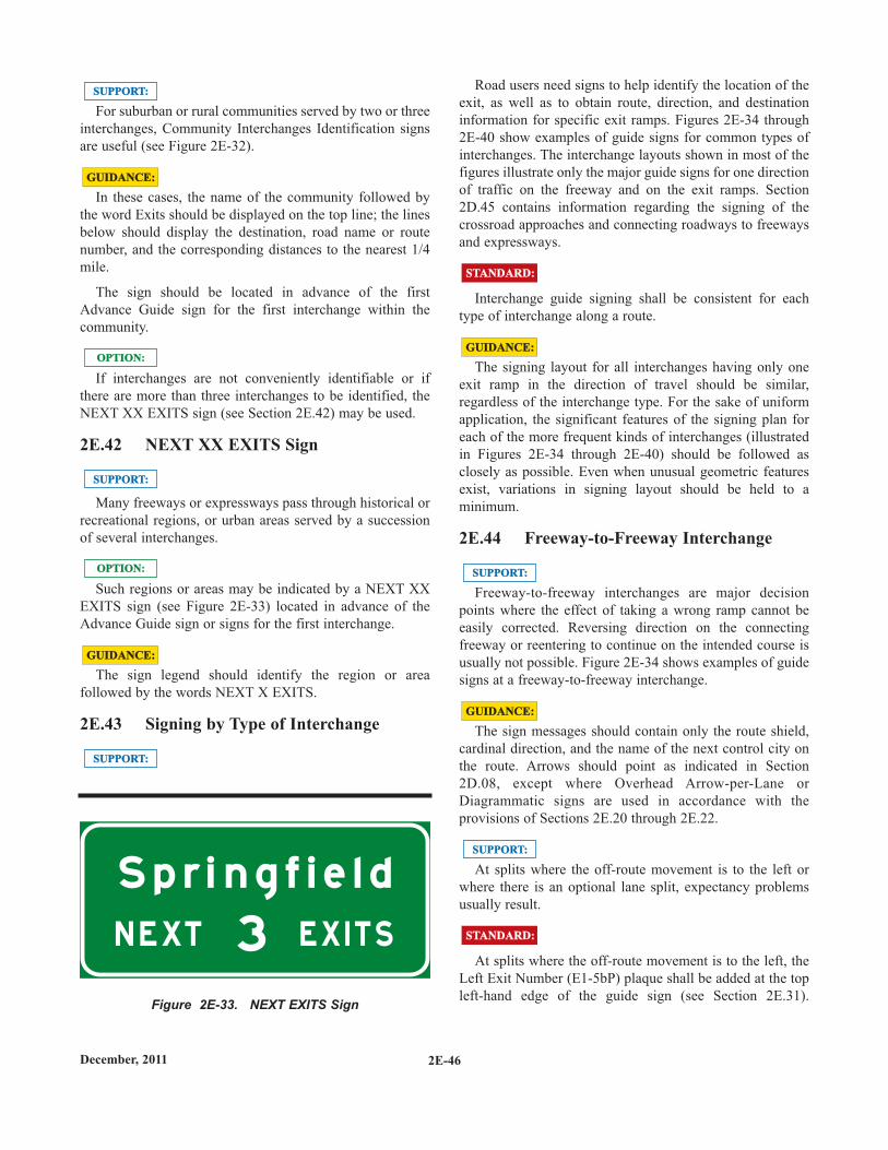
2E-46December, 2011
For suburban or rural communities served by two or threeinterchanges, Community Interchanges Identification signsare useful (see Figure 2E-32).
In these cases, the name of the community followed bythe word Exits should be displayed on the top line; the linesbelow should display the destination, road name or routenumber, and the corresponding distances to the nearest 1/4mile.
The sign should be located in advance of the firstAdvance Guide sign for the first interchange within thecommunity.
If interchanges are not conveniently identifiable or ifthere are more than three interchanges to be identified, theNEXT XX EXITS sign (see Section 2E.42) may be used.
2E.42 NEXT XX EXITS Sign
Many freeways or expressways pass through historical orrecreational regions, or urban areas served by a successionof several interchanges.
Such regions or areas may be indicated by a NEXT XXEXITS sign (see Figure 2E-33) located in advance of theAdvance Guide sign or signs for the first interchange.
The sign legend should identify the region or areafollowed by the words NEXT X EXITS.
2E.43 Signing by Type of Interchange
SUPPORT:SUPPORT:
GUIDANCE:GUIDANCE:
OPTION:OPTION:
SUPPORT:SUPPORT:
OPTION:OPTION:
GUIDANCE:GUIDANCE:
SUPPORT:SUPPORT:Road users need signs to help identify the location of the
exit, as well as to obtain route, direction, and destinationinformation for specific exit ramps. Figures 2E-34 through2E-40 show examples of guide signs for common types ofinterchanges. The interchange layouts shown in most of thefigures illustrate only the major guide signs for one directionof traffic on the freeway and on the exit ramps. Section2D.45 contains information regarding the signing of thecrossroad approaches and connecting roadways to freewaysand expressways.
Interchange guide signing shall be consistent for eachtype of interchange along a route.
The signing layout for all interchanges having only oneexit ramp in the direction of travel should be similar,regardless of the interchange type. For the sake of uniformapplication, the significant features of the signing plan foreach of the more frequent kinds of interchanges (illustratedin Figures 2E-34 through 2E-40) should be followed asclosely as possible. Even when unusual geometric featuresexist, variations in signing layout should be held to aminimum.
2E.44 Freeway-to-Freeway Interchange
Freeway-to-freeway interchanges are major decisionpoints where the effect of taking a wrong ramp cannot beeasily corrected. Reversing direction on the connectingfreeway or reentering to continue on the intended course isusually not possible. Figure 2E-34 shows examples of guidesigns at a freeway-to-freeway interchange.
The sign messages should contain only the route shield,cardinal direction, and the name of the next control city onthe route. Arrows should point as indicated in Section2D.08, except where Overhead Arrow-per-Lane orDiagrammatic signs are used in accordance with theprovisions of Sections 2E.20 through 2E.22.
At splits where the off-route movement is to the left orwhere there is an optional lane split, expectancy problemsusually result.
At splits where the off-route movement is to the left, theLeft Exit Number (E1-5bP) plaque shall be added at the topleft-hand edge of the guide sign (see Section 2E.31).
SUPPORT:SUPPORT:
GUIDANCE:GUIDANCE:
STANDARD:STANDARD:
GUIDANCE:GUIDANCE:
STANDARD:STANDARD:
SUPPORT:SUPPORT:
S p r i n g f i e l d
3N E XT E X I T S
Figure 2E-33. NEXT EXITS Sign
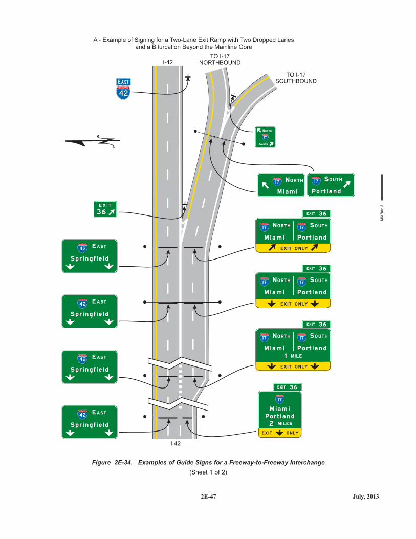
2E-47 July, 2013
Figure 2E-34. Examples of Guide Signs for a Freeway-to-Freeway Interchange(Sheet 1 of 2)
36
P o rt l a n d
P o rt l a n d
P o rt l a n d
P o rt l a n d
P o rt l a n d
M i a m i
M i a m i
M i a m i
M i a m i
M i a m i
N O R T H
N O R T H
N O R T H
N O R T H
S O U T H
S O U T H
S O U T H
S O U T H
M I LES
M I LE
2
1
EX I T 36
EX I T 36
EX I T 36
EX I T 36
S p r i n g f i e l d
E AS T42
INTERSTATE
S p r i n g f i e l d
E AS T42
INTERSTATE
S p r i n g f i e l d
E AS T42
INTERSTATE
S p r i n g f i e l d
E AS T42
INTERSTATE
4 2
INTERSTATE
EE ASTAST
I-42
TO I-17NORTHBOUND
TO I-17SOUTHBOUND
E X I T O N LY
1 7
INTERSTATE
1 7
INTERSTATE
1 7
INTERSTATE
1 7
INTERSTATE
1 7
INTERSTATE
1 7
INTERSTATE
1 7
INTERSTATE
1 7
INTERSTATE
1 7
INTERSTATE
E X I T O N LY
E X I T O N LY
E X I T O N LY
A - Example of Signing for a Two-Lane Exit Ramp with Two Dropped Lanesand a Bifurcation Beyond the Mainline Gore
N O R T H
1 7
INTERSTATE
S O U T H
I-42
MN
Rev
. 2
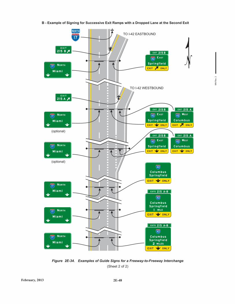
2E-48February, 2013
Figure 2E-34. Examples of Guide Signs for a Freeway-to-Freeway Interchange(Sheet 2 of 2)
S p r i n g f i e l d
S p r i n g f i e l d
S p r i n g f i e l d
C o l u m b u s
C o l u m b u s
C o l u m b u s
M I LES2
M I LE1
1 7
INTERSTATE TO I-42 EASTBOUND
TO I-42 WESTBOUND
E X I T O N LY
E X I T O N LY
E X I T O N LY
42
INTERSTATE
4 2
INTERSTATE
B - Example of Signing for Successive Exit Ramps with a Dropped Lane at the Second Exit
42
INTERSTATE
M i a m i
1 7
INTERSTATE
N O R T H
M i a m i
1 7
INTERSTATE
N O R T H
M i a m i
1 7
INTERSTATE
N O R T H
M i a m i
1 7
INTERSTATE
N O R T H
(optional)
M i a m i
1 7
INTERSTATE
N O R T H
(optional)
M i a m i
1 7
INTERSTATE
N O R T H
2 1 5 A
2 1 5 B
NN O RTHO RTH
EX I TS 2 1 5 A- B
EX I TS 2 1 5 A- B
EX I T 2 1 5 B
EX I T 2 1 5 B
EX I T 2 1 5 B
EX I T 2 1 5 A
EX I T 2 1 5 A
S p r i n g f i e l d
S p r i n g f i e l d
S p r i n g f i e l d
C o l u m b u s
C o l u m b u s
42
INTERSTATE
E AS T
42
INTERSTATE
E AS T
42
INTERSTATE
E AS T
42
INTERSTATE
WES T
42
INTERSTATE
WES T
E X I T O N LY
E X I T O N LY
E X I T O N LY
E X I T O N LY
E X I T O N LY
MN
Rev
. 2
2E-49 December, 2011
Overhead Arrow-per-Lane or Diagrammatic guide signs (seeSections 2E.21 and 2E.22) shall be used for freeway splitswith an option lane and for multi-lane freeway-to-freewayexits having an option lane.
Overhead signs shall be used at a distance of 1 mile andat the theoretical gore of each connecting ramp. WhenOverhead Arrow-per-Lane or Diagrammatic guide signs areused, they shall comply with the provisions of Sections2E.21 and 2E.22.
Overhead signs may also be used at the 1/2-mile and 2-mile locations.
The arrow and/or the name of the control city may beomitted on signs that indicate the straight-ahead continua-tion of a route on a Pull-Through sign (see Section 2E.12).
An Advisory Exit Speed sign may be used where anengineering study shows that it is necessary to display aspeed reduction message for ramp signing (see Section2C.14).
Where extra emphasis of an especially low advisory rampspeed is needed, an EXIT XX MPH (E13-2) sign panel (seeFigure 2E-27) may be placed at the bottom of the ExitDirection sign to supplement, but not to replace, the exit orramp advisory speed warning signs.
2E.45 Cloverleaf Interchange
A cloverleaf interchange has two exits for each directionof travel. The exits are closely spaced and have commonAdvance Guide signs. Examples of guide signs forcloverleaf interchanges are shown in Figure 2E-35.
The Advance Guide signs should include two placenames, one corresponding to each exit ramp, with the nameof the place served by the first exit on the upper line.
An overhead guide sign shall be placed at the theoreticalgore of the first exit ramp, with a diagonally upward-pointing directional arrow on the Exit Direction sign for thatexit and the message XX MILES, or EXIT XX MILES ifinterchange numbering is not used, on the Advance Guidesign for the second exit, as shown in Figure 2E-35. Thesecond exit shall be indicated by an overhead Exit Directionsign over the auxiliary lane. An Exit Gore sign shall also beused at each gore (see Section 2E.37).
Interchanges with more than one exit from the main lineshall be numbered as described in Section 2E.31 with anappropriate suffix.
Diagrammatic signs shall not be used for cloverleaf inter-
OPTION:OPTION:
SUPPORT:SUPPORT:
GUIDANCE:GUIDANCE:
STANDARD:STANDARD:
changes except as otherwise provided in Section 2E.22.
Where the mainline passes under the crossroad and theexit roadway is located beyond the overcrossing structure,the overhead Exit Direction sign for the second exit shouldbe placed either on the overcrossing structure (see Figure2E-35) or on a separate structure located immediately infront of the overcrossing structure.
2E.46 Cloverleaf Interchange withCollector-Distributor Roadways
Examples of guide signs for full cloverleaf interchangeswith collector-distributor roadways are shown in Figure 2E-36.
Signing on the collector-distributor roadways should bethe same as the signing on the mainline of a cloverleafinterchange.
Guide signs at exits from the collector-distributorroadways shall be overhead and located at the theoreticalgore of the collector-distributor roadway and the exit ramp.
Exits from the collector-distributor roadways may benumbered with an appropriate suffix. If the exits from acollector-distributor roadway are numbered with suffixes,the Advance Guide signs on the mainline may include twoplace names and their corresponding exit numbers with theplural EXITS. If only the exit from the mainline is numberedor if interchange numbering is not used, the Advance Guidesigns on the mainline may use the singular EXIT.
Both cardinal directions should be used on the guidesigns prior to the collector-distributor road exit when acollector-distributor road serves both directions.
2E.47 Partial Cloverleaf Interchange
Examples of guide signs for partial cloverleaf inter-changes are shown in Figure 2E-37.
Where the mainline passes under the crossroad and theexit roadway is located beyond the overcrossing structure,the overhead Exit Direction sign should be placed either onthe overcrossing structure (see Figure 2E-37) or on aseparate structure located immediately in front of the over-
SUPPORT:SUPPORT:
GUIDANCE:GUIDANCE:
STANDARD:STANDARD:
OPTION:OPTION:
GUIDANCE:GUIDANCE:
GUIDANCE:GUIDANCE:
SUPPORT:SUPPORT:
GUIDANCE:GUIDANCE:
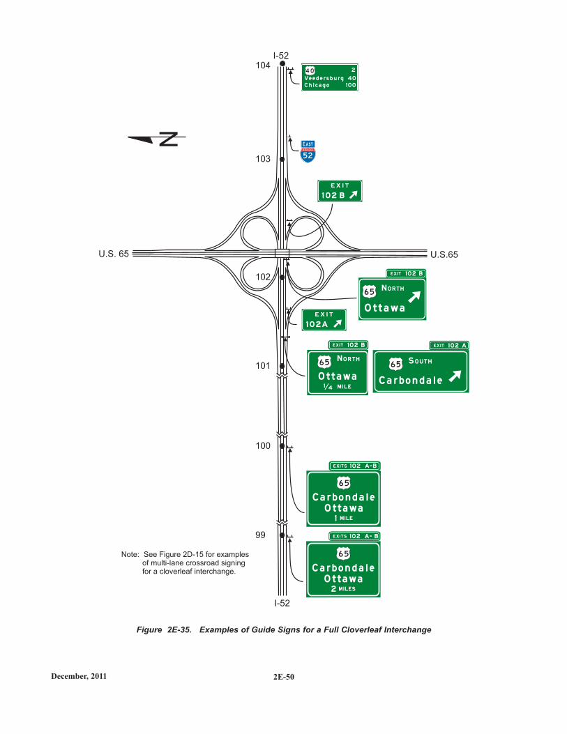
2E-50December, 2011
Figure 2E-35. Examples of Guide Signs for a Full Cloverleaf Interchange
99
100
101
103
102
1042
Ve e d e rs b u rg 40C h i c a g o 1 00
52
INTERSTATE
E X I T
E X I T
1 0 2 B
1 0 2A
1 0 2 BEX I T
1 02 BEX I T
1 02 A- BEX I TS
1 02 A- BEX I TS
1 02 AEX I T
O t t a wa
C a r b o n d a l e
6 5
4 0
6 5
O t t a wa
6 5
C a r b o n d a l eO t t a wa
M I LES2
6 5
C a r b o n d a l eO t t a wa
M I LE1
6 5
U.S. 65
I-52
U.S.65
I-52
Note: See Figure 2D-15 for examplesof multi-lane crossroad signingfor a cloverleaf interchange.
N EE ASTAST
N O R T H
N O R T H
S O U T H
1 4 M I L E
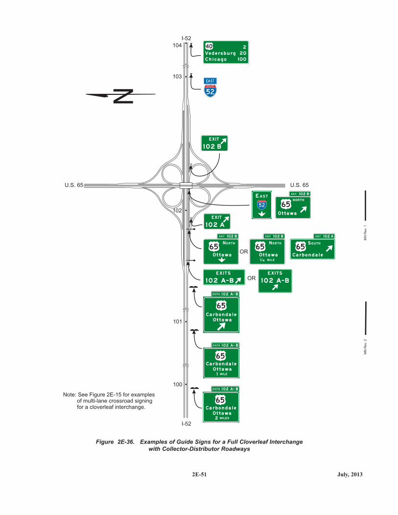
2E-51 July, 2013
Figure 2E-36. Examples of Guide Signs for a Full Cloverleaf Interchangewith Collector-Distributor Roadways
I-52
U.S. 65U.S. 65
I-52
104
103
102
101
OR
OR
100
Note: See Figure 2E-15 for examplesof multi-lane crossroad signingfor a cloverleaf interchange.
EX I T
1 0 2 A
EX I T
1 0 2 B
EX I TS 1 0 2 A- B
EX I TS 1 0 2 A- B
EX I TS 1 0 2 A- B
N O RTH
EAST
E X I T S E X I T S
1 0 2 A- B 1 0 2 A- B
NO R T H N O R T H S O U T H
1 4 M I L E
E A S T
52
INTERSTATE
MN
Rev
. 1M
N R
ev. 2
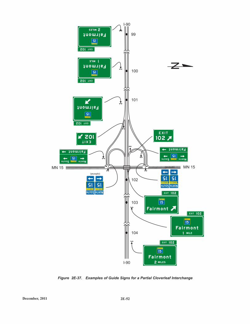
2E-52December, 2011
Figure 2E-37. Examples of Guide Signs for a Partial Cloverleaf Interchange
104
99
103
100
102
101
Fa i r m o n t
M I LES2
1 5
Fairmont
MILES 2
15
Fa i r m o n t
M I LE1
1 5
Fairmont
MILE 1
15
Fa i r m o n t
1 5
Fairmont
15
I-90
MN 15 MN 15
I-90
N
102
1 02
EXIT102
EXIT102
EXIT102
EX I T 1 0 2
EX I T 1 0 2
EX I T 1 0 2
Fairmont
15
NORTHSOUTH
Fairmont
15
NORTHSOUTH
1515
NNORTH ORTHSSOUTH OUTH
(optional)
1515
NNORTH ORTHSSOUTH OUTH
(optional)
2E-53 December, 2011
crossing structure..
A post-mounted Exit Gore sign shall also be installed inthe ramp gore.
Partial cloverleaf interchanges with successive exit rampsfrom the same direction of travel are signed the same ascloverleaf interchanges for that direction of travel (seeSection 2E.45).
2E.48 Diamond Interchange
Examples of guide signs for diamond interchanges areshown in Figure 2E-38.
For numbered exits, the singular message EXIT shall beused on the Exit Number plaques (see Section 2E.31) withthe Advance Guide and Exit Direction signs. For non-numbered exits, the singular message EXIT shall be used aspart of the distance message on the Advance Guide signs.
The typical diamond interchange ramp departs from themainline roadway such that a speed reduction generally isnot necessary in order for a driver to negotiate an exitmaneuver from the mainline onto the ramp roadway.
When a speed reduction is not necessary, an exit speedsign should not be used.
An Advisory Exit Speed sign may be used where anengineering study shows that it is necessary to display aspeed reduction message for ramp signing (see Section2C.14).
The Advisory Exit Speed sign should be located along thedeceleration lane or along the ramp such that it is visible tothe driver far enough in advance to allow the driver todecelerate before reaching the curve associated with theexiting maneuver.
A Stop Ahead or Signal Ahead warning sign may beplaced, where engineering judgment indicates a need, alongthe ramp in advance of the cross street, to give notice to the
SUPPORT:SUPPORT:
SUPPORT:SUPPORT:
STANDARD:STANDARD:
SUPPORT:SUPPORT:
GUIDANCE:GUIDANCE:
OPTION:OPTION:
GUIDANCE:GUIDANCE:
OPTION:OPTION:
STANDARD:STANDARD:
driver (see Section 2C.36).
When used on two-lane ramps, Stop Ahead or SignalAhead signs should be used in pairs with one sign on eachside of the ramp.
2E.49 Diamond Interchange in Urban Area
Examples of guide signs for diamond interchanges in anurban area are shown in Figure 2E-39. This exampleincludes the use of the Community InterchangesIdentification sign (see Section 2E.41), which might beuseful if two or more interchanges serve the samecommunity.
In urban areas, street names are often displayed as theprincipal message in destination signs.
If interchanges are too closely spaced to properly locatethe Advance Guide signs, they may be placed closer to theexit with the distances displayed adjusted accordingly.
2E.50 Closely Spaced Interchanges
Section 2E.11 contains information regarding signspreading where the Exit Direction sign and the AdvanceGuide sign for the next interchange are mounted overhead.Sign spreading is particularly beneficial where interchangesare closely spaced and overhead signing is used inconjunction with Interchange Sequence signs as provided inthe following paragraph.
Interchange Sequence signs (see Section 2E.40) should beused at closely-spaced interchanges. When used, they shouldidentify and show street names and distances for the nexttwo or three exits as shown in Figure 2E-30.
Advance Guide signs for closely spaced interchangesshall show information for only one interchange.
2E.51 Minor Interchange
Less signing may be used for minor interchanges becausesuch interchanges customarily serve low volumes of localtraffic.
Examples of guide signs for minor interchanges areshown in Figure 2E-40.
SUPPORT:SUPPORT:
OPTION:OPTION:
OPTION:OPTION:
GUIDANCE:GUIDANCE:
STANDARD:STANDARD:
OPTION:OPTION:
SUPPORT:SUPPORT:
GUIDANCE:GUIDANCE:
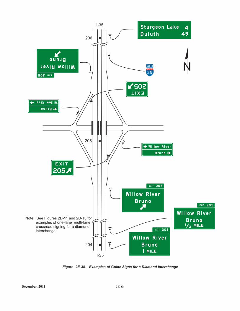
2E-54December, 2011
Figure 2E-38. Examples of Guide Signs for a Diamond Interchange
3 5
INTERSTATE
N O RTH
B r u n o
W i l l ow R i v e r
Bruno
Willow River
204
206
205
D u l u t h 49
4S t u rg e o n La k e
B r u n o
W i l l ow R i v e r
12/ M I L E
B r u n o
Bruno
W i l l ow R i v e r
Willow RiverB r u n o
W i l l ow R i v e r
1 M I L E
I-35
I-35
Note: See Figures 2D-11 and 2D-13 forexamples of one-lane multi-lanecrossroad signing for a diamondinterchange.
N
205
205E X I T 2 0 5
EX I T 2 0 5
EX I T 2 0 5
EXIT205
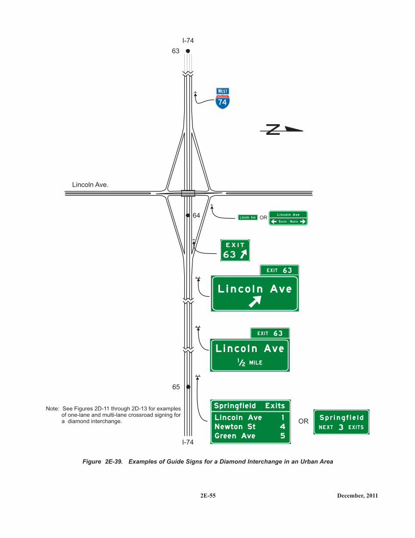
2E-55 December, 2011
Figure 2E-39. Examples of Guide Signs for a Diamond Interchange in an Urban Area
63
65
64
L i n co l n Ave
S p r i n g f i e l d ` Ex i ts
1
N ewto n St 4
G ree n Ave 5
OR
L i n c o l n Ave
/ M I LE12
L i n c o l n Ave
63
E X I T
Lincoln Ave.
I-74
I-74
Note: See Figures 2D-11 through 2D-13 for examplesof one-lane and multi-lane crossroad signing fora diamond interchange.
N
S p r i n g f i e l d
3N E XT E X I T S
E X I T 6 3
EX I T 6 3
74
INTERSTATE
WWESTEST
L i n co l n AveL i n c o l n Ave
N O R T HS O U T HOR
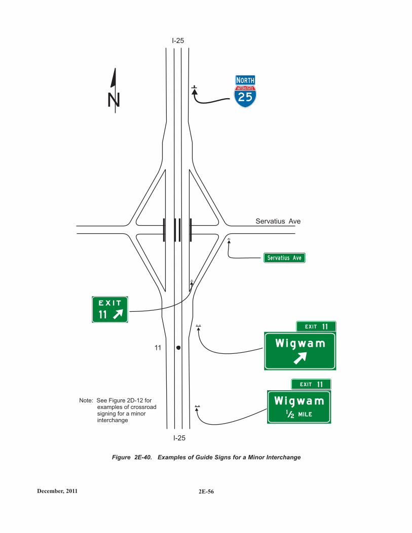
2E-56December, 2011
Figure 2E-40. Examples of Guide Signs for a Minor Interchange
W i g wa m/ M I LE12
W i g wa m11
1 1
E X I T
2 5
INTERSTATE
I-25
I-25
Note: See Figure 2D-12 forexamples of crossroadsigning for a minorinterchange
N
NN O RTHO RTH
Servatius Ave
E X I T 1 1
E X I T 1 1
Se rva t i u s Ave

2E-57 December, 2011
At least one Advance Guide sign and an Exit Gore signshall be used at a minor interchange.
An Exit Direction sign should also be used.
2E.52 Signing on Conventional RoadApproaches andConnecting Roadways
Section 2D.45 contains information regarding the signingon conventional roads on the approaches to interchanges andthe signing on connecting roadways.
2E.53 Wrong-Way Traffic Control atInterchange Ramps
Section 2B.41 contains information regarding the use ofregulatory signs to deter wrong-way movements at intersec-tions of freeway or expressway ramps with conventionalroads, and in the area where entrance ramps intersect withthe mainline lanes.
Section 2D.46 contains information regarding the use of aDirectional assembly or a guide sign to mark the entrance toa freeway or expressway from a conventional road.
2E.54 Weigh Station Signing
Weigh Station signing on freeways and expressways shallbe the same as that provided in Section 2D.49, except forlettering size and the advance posting distance for the ExitDirection sign, which shall be located a minimum of 1,500feet in advance of the gore.
Weigh Station sign layouts for expressway and freewayapplications are available from MnDOT (see Office ofTraffic, Safety and Technology, page ii).
SUPPORT:SUPPORT:
STANDARD:STANDARD:
SUPPORT:SUPPORT:
SUPPORT:SUPPORT:
GUIDANCE:GUIDANCE:
STANDARD:STANDARD: