part 6-1: hydraulic machinery and turbine generator
TRANSCRIPT

Technical Guidelines for the Development of Small Hydropower PlantsDesign
Part 6-1: Hydraulic Machineryand Turbine generator
sHP/Tg 002-6-1: 2019

D i s C L A i M e R
This document has been produced without formal United Nations editing. The designations and the presentation of the material in this document do not imply the expression of any opinion whatsoever on the part of the Secretariat of the United Nations Industrial Development Organization (UNIDO) concerning the legal status of any country, territory, city or area of its authorities, or concerning the delimitation of its frontiers or boundaries, or its economic system or degree of development. Designations such as “developed”, “industrialized” and “developing” are intended for statistical convenience and do not necessarily express a judgement about the stage reached by a particular country or area in the development process. Mention of company names or commercial products does not constitute an endorsement by UNIDO. Although great care has been taken to maintain the accuracy of information herein, neither UNIDO nor its Member States assume any responsibility for consequences which may arise from the use of the material. This document may be freely quoted or reprinted but acknowledgement is requested.
© 2019 UNIDO / INSHP- All rights reserved

Technical Guidelines for the Development of Small Hydropower PlantsDesign
Part 6-1: Hydraulic Machineryand Turbine generator
sHP/Tg 002-6-1: 2019

Technical Guidelines for the Development of Small Hydropower Plants – Design
SHP/TG 002-6-1: 2019iV
ACKNOWLEDGEMENTSThe technical guidelines (TGs) are the result of a collaborative effort between the United Nations Industrial Development Organization (UNIDO) and the International Network on Small Hydro Power (INSHP). About 80 international experts and 40 international agencies were involved in the document’s preparation and peer review, and they provided concrete comments and suggestions to make the TGs professional and applicable.
UNIDO and the INSHP highly appreciate the contributions provided during the development of these guidelines and in particular those delivered by the following international organizations:
- The Common Market for Eastern and Southern Africa(COMESA)
- The Global Network of Regional Sustainable Energy Centres (GN-SEC), particularly the ECOWAS Centre for Renewable Energy and Energy Efficiency (ECREEE), the East African Centre for Renewable Energy and Energy Efficiency (EACREEE), the Pacific Centre for Renewable Energy and Energy Efficiency (PCREEE) and the Caribbean Centre for Renewable Energy and Energy Efficiency (CCREEE).
The Chinese government has facilitated the finalization of these guidelines and was of great importance to its completion.
The development of these guidelines benefited greatly from the valuable inputs, review and constructive comments as well as contributions received from Mr. Adnan Ahmed Shawky Atwa, Mr. Adoyi John Ochigbo, Mr. Arun Kumar, Mr. Atul Sarthak, Mr. Bassey Edet Nkposong, Mr. Bernardo Calzadilla-Sarmiento, Ms. Chang Fangyuan, Mr. Chen Changju, Ms. Chen Hongying , Mr. Chen Xiaodong, Ms. Chen Yan, Ms. Chen Yueqing, Ms. Cheng Xialei, Ms. Chileshe Kapaya Matantilo, Ms. Chileshe Mpundu Kapwepwe, Mr. Deogratias Kamweya, Mr. Dolwin Khan, Mr. Dong Guofeng, Mr. Ejaz Hussain Butt, Ms. Eva Kremere, Ms. Fang Lin, Mr. Fu Liangliang, Mr. Garaio Donald Gafiye, Mr. Guei Guillaume Fulbert Kouhie, Mr. Guo Chenguang, Mr. Guo Hongyou, Mr. Harold John Annegam, Ms. Hou Ling, Mr. Hu Jianwei, Ms. Hu Xiaobo, Mr. Hu Yunchu, Mr. Huang Haiyang, Mr. Huang Zhengmin, Ms. Januka Gyawali, Mr. Jing Songkun, Mr. K. M. Dharesan Unnithan, Mr. Kipyego Cheluget, Mr. Kolade Esan, Mr. Lamyser Castellanos Rigoberto, Mr. Li Zhiwu, Ms. Li Hui, Mr. Li Xiaoyong, Ms. Li Jingjing, Ms. Li Sa, Mr. Li Zhenggui, Ms. Liang Hong, Mr. Liang Yong, Mr. Lin Xuxin, Mr. Liu Deyou, Mr. Liu Heng, Mr. Louis Philippe Jacques Tavernier, Ms. Lu Xiaoyan, Mr. Lv Jianping, Mr. Manuel Mattiat, Mr. Martin Lugmayr, Mr. Mohamedain Seif Elnasr, Mr. Mundia Simainga, Mr. Mukayi Musarurwa, Mr. Olumide Taiwo Alade, Mr. Ou Chuanqi, Ms. Pan Meiting, Mr. Pan Weiping, Mr. Ralf Steffen Kaeser, Mr. Rudolf Hüpfl, Mr. Rui Jun, Mr. Rao Dayi, Mr. Sandeep Kher, Mr. Sergio Armando Trelles Jasso, Mr. Sindiso Ngwenga, Mr. Sidney Kilmete, Ms. Sitraka Zarasoa Rakotomahefa, Mr. Shang Zhihong, Mr. Shen Cunke, Mr. Shi Rongqing, Ms. Sanja Komadina, Mr. Tareq Emtairah, Mr. Tokihiko Fujimoto, Mr. Tovoniaina Ramanantsoa Andriampaniry, Mr. Tan Xiangqing, Mr. Tong Leyi, Mr. Wang Xinliang, Mr. Wang Fuyun, Mr. Wei Jianghui, Mr. Wu Cong, Ms. Xie Lihua, Mr. Xiong Ji, Ms. Xu Jie, Ms. Xu Xiaoyan, Mr. Xu Wei, Mr. Yohane Mukabe, Mr. Yan Wenjiao, Mr. Yang Weijun, Ms. Yan Li, Mr. Yao Shenghong, Mr. Zeng Jingnian, Mr. Zhao Guojun, Mr. Zhang Min, Mr. Zhang Liansheng, Mr. Zhang Zhenzhong, Mr. Zhang Xiaowen, Ms. Zhang Yingnan, Mr. Zheng Liang, Mr. Zheng Xiongwei, Mr. Zheng Yu, Mr. Zhou Shuhua, Ms. Zhu Mingjuan.
Further recommendations and suggestions for application for the update would be highly welcome.

SHP/TG 002-6-1: 2019
Part 6-1: Hydraulic Machinery and Turbine Generator
V
Table of ContentsForeword VII
Introduction VIII
1 Scope 1
2 Normative references 1
3 Terms and definitions 1
4 Turbine 14.1 General requirements for turbine type selection 14.2 Selection of the rated head 34.3 Turbine type selection 34.4 Selection of the basic parameters of the reaction turbine 54.5 Selection of basic parameters of the Pelton turbine 74.6 Calculation of the regulation guarantee of the unit 9
5 Generator 95.1 General requirements for generator type selection 105.2 Rated data and main parameter selection 105.3 Selection of the generator mechanical structure 155.4 Generator auxiliary system 16
6 Turbine governing system 176.1 Basic principles for governing system type selection 176.2 Operating capacity of the governor 186.3 Control system of governor 18
7 Main valve of the turbine 197.1 Basic principles for the main valve type selection 197.2 Selection of the main valve 197.3 The seal type selection of the main valve 21
8 Auxiliary system 218.1 Technical water supply and the drainage systems 218.2 Oil system 228.3 Compressed air system 228.4 Hydraulic monitoring system 238.5 Selection of the lifting equipment 238.6 Heating and ventilation 238.7 Allocation of maintenance equipment for the electro-mechanical equipment 248.8 Schematic diagrams of typical oil, air and water systems 24
9 Fire extinguishing system 249.1 Basic principle for the design of the fire extinguishing system 249.2 Technical requirements 24

Technical Guidelines for the Development of Small Hydropower Plants – Design
SHP/TG 002-6-1: 2019Vi
10 Layout of the powerhouse 2510.1 Basic principle for the layout of the powerhouse 2510.2 Technical requirements 25
Appendix A (Normative) Reference formula for the basic parameter calculation for the reaction turbine 27
Appendix B (Normative) Reference formula for the basic parameter calculation of the impulse turbine 32
Appendix C (Normative) Reference formula for the working capacity calculation of the governing system for some turbines 36

SHP/TG 002-6-1: 2019
Part 6-1: Hydraulic Machinery and Turbine Generator
Vii
ForewordThe United Nations Industrial Development Organization (UNIDO) is a specialized agency under the United Nations system to promote globally inclusive and sustainable industrial development (ISID). The relevance of ISID as an integrated approach to all three pillars of sustainable development is recognized by the 2030 Agenda for Sustainable Development and the related Sustainable Development Goals (SDGs), which will frame United Nations and country efforts towards sustainable development in the next fifteen years. UNIDO’s mandate for ISID covers the need to support the creation of sustainable energy systems as energy is essential to economic and social development and to improving quality of life. International concern and debate over energy have grown increasingly over the past two decades, with the issues of poverty alleviation, environmental risks and climate change now taking centre stage.
INSHP (International Network on Small Hydro Power) is an international coordinating and promoting organization for the global development of small hydropower (SHP), which is established on the basis of voluntary participation of regional, subregional and national focal points, relevant institutions, utilities and companies, and has social benefit as its major objective. INSHP aims at the promotion of global SHP development through triangle technical and economic cooperation among developing countries, developed countries and international organizations, in order to supply rural areas in developing countries with environmentally sound, affordable and adequate energy, which will lead to the increase of employment opportunities, improvement of ecological environments, poverty alleviation, improvement of local living and cultural standards and economic development.
UNIDO and INSHP have been cooperating on the World Small Hydropower Development Report since year 2010. From the reports, SHP demand and development worldwide were not matched. One of the development barriers in most countries is lack of technologies. UNIDO, in cooperation with INSHP, through global expert cooperation, and based on successful development experiences, decided to develop the SHP TGs to meet demand from Member States.
These TGs were drafted in accordance with the editorial rules of the ISO/IEC Directives, Part 2 (see www.iso.org/directives).
Attention is drawn to the possibility that some of the elements of these TGs may be subject to patent rights. UNIDO and INSHP shall not be held responsible for identifying any such patent rights.

Technical Guidelines for the Development of Small Hydropower Plants – Design
SHP/TG 002-6-1: 2019Viii
IntroductionSmall Hydropower (SHP) is increasingly recognized as an important renewable energy solution to the challenge of electrifying remote rural areas. However, while most countries in Europe, North and South America, and China have high degrees of installed capacity, the potential of SHP in many developing countries remains untapped and is hindered by a number of factors including the lack of globally agreed good practices or standards for SHP development.
These Technical Guidelines for the Development of Small Hydropower Plants (TGs) will address the current limitations of the regulations applied to technical guidelines for SHP Plants by applying the expertise and best practices that exist across the globe. It is intended for countries to utilize these agreed upon Guidelines to support their current policy, technology and ecosystems. Countries that have limited institutional and technical capacities, will be able to enhance their knowledge base in developing SHP plants, thereby attracting more investment in SHP projects, encouraging favourable policies and subsequently assisting in economic development at a national level. These TGs will be valuable for all countries, but especially allow for the sharing of experience and best practices between countries that have limited technical know-how.
The TGs can be used as the principles and basis for the planning, design, construction and management of SHP plants up to 30MW.
• The Terms and Definitions in the TGs specify the professional technical terms and definitions commonly used for SHP Plants.
• The Design Guidelines provide guidelines for basic requirements, methodology and procedure in terms of site selection, hydrology, geology, project layout, configurations, energy calculations, hydraulics, electromechanical equipment selection, construction, project cost estimates, economic appraisal, financing, social and environmental assessments—with the ultimate goal of achieving the best design solutions.
• Units Guidelines specify the technical requirements on SHP turbines, generators, hydro turbine governing systems, excitation systems, main valves as well as monitoring, control, protection and DC power supply systems.
• The Construction Guidelines can be used as the guiding technical documents for the construction of SHP projects.
• The Management Guidelines provide technical guidance for the management, operation and maintenance, technical renovation and project acceptance of SHP projects.

SHP/TG 002-6-1: 2019
Part 6-1: Hydraulic Machinery and Turbine Generator
1
Technical Guidelines for the Development of Small Hydropower PlantsDESIGN
Part 6-1: Hydraulic Machineryand Turbine Generator

Technical Guidelines for the Development of Small Hydropower Plants – Design
SHP/TG 002-6-1: 20192
1 ScopeThis Part of Design Guidelines specifies the type selection design and the arrangement of the main and auxiliary hydraulic machinery, the type selection design and arrangement of the turbine as well as the design of the heating, ventilation and fire control systems of the SHP station. It includes the basic principles of the type selection for the different machines, the selection and calculation of the basic parameters, the scheme comparison as well as the examples of typical diagrams of the different powerhouse layouts.
2 Normative referencesThe following documents are referred to in the text in such a way that some or all of their content constitutes requirements of this document. For dated references, only the edition cited applies. For undated references, the latest edition of the referenced document (including any amendments) applies.
SHP/TG 001, Technical guidelines for the development of small hydropower plants —Terms and definitions.
3 Terms and definitionsFor the purposes of this document, the terms and definitions given in IEC TR 61364 and SHP/TG 001 apply.
4 Turbine
4.1 General requirements for turbine type selection4.1.1 The turbine type and the basic parameters shall be selected through technical and economic comparison in accordance with the hydraulic energy parameters, the layout of the hydropower station and its operating characteristics, the technical features, economic indexes, operation reliability, technical level of the design and manufacture, the transportation and in combination with the field conditions.
4.1.2 The turbine type selection shall include the following contents:
a) Selection of the type and installation mode;
b) Selection of the number of installed units and the unit capacity;
c) Selection of the rated head of the turbine;
d) Selection of the basic parameters of the turbine, including the shaft power, runner diameter, rated speed, rated discharge, efficiency, draft height and the setting elevation. For the impulse turbine, it is necessary to select the jet diameter, number of nozzles and the draining height;
e) Selection of the appropriate model runner and the plotting of the turbine operating characteristic curve;
f) Estimation of the overall dimensions, weight and cost of the main components of the turbine;
4.1.3 Basic information for the selection of the hydropower station particulars shall include:
a) Operating head of the turbine (including the maximum head, minimum head and weighted average head).

SHP/TG 002-6-1: 2019
Part 6-1: Hydraulic Machinery and Turbine Generator
3
b) Water intake system of the hydropower station;
c) Installed capacity of the hydropower station;
d) Upstream/downstream water levels;
e) Parameters of the power generation and water conveyance systems (including the type, arrangement, length, pipe diameter and head losses of all the water conveyance systems from the water inlet for the generation to the tailwater outlet of the hydropower station);
f) Tailwater level versus the discharge relation curve;
g) Guaranteed output of the hydropower station, the power weighting factor can be provided when necessary;
h) Operation mode of the hydropower station in the electrical power system, reservoir operation and power evacuation modes;
i) Quality of the water passing through the turbine (including the sediment concentration through the turbine, the particle size grading, Moh’s hardness, mineral composition, PH value and water temperature);
j) Meteorological conditions of the hydropower station (including the air temperature, water temperature and relative humidity);
k) Geographic position of the hydropower station (including the sea level elevation, atmospheric pressure and gravitational acceleration of powerhouse).
4.2 Selection of the rated head4.2.1 The rated head shall be selected through technical and economic comparison in accordance with the head variation of the hydropower station, the regulating characteristic of the reservoir, the stable operation requirements of the unit, the operation mode of the hydropower station in the electrical power system and the characteristics of the power generation and water conductor systems.
4.2.2 As for the hydropower station with the medium/high head, the rated head should be selected within the scope of 0.85 to 0.95 times the weighted average head.
4.2.3 As for the run-of-river hydropower station, the rated head shall guarantee that the hydropower station may generate the installed capacity.
4.2.4 As for the hydropower station on an overloaded river with the reservoir operating in a mode of “storing clear water and discharging muddy water”, the rated head should be selected within the scope between the weighted average head and the lower limit productive head in the storage period of the reservoir.
4.2.5 When the rated head is close to the minimum head, it is necessary to demonstrate its rationality and economic efficiency. With regard to the impulse turbine with high head with small variation of the reservoir water level, the minimum head may be used as the rated head of the turbine.
4.3 Turbine type selection4.3.1 The turbine type shall be selected within the operation head scope in accordance with the basic principles in 4.1. See Table 1 for the common turbine types and the applicable head scope.

Technical Guidelines for the Development of Small Hydropower Plants – Design
SHP/TG 002-6-1: 20194
Table 1 Turbine types and the applicable head scope
Turbine typeApplicable head scope, mClassification as per the
energy conversion modeClassification as per the
water flow directionClassification as per the
structural feature
Reaction turbine
Through-flow turbine
Bulb turbine
3~30shaft-extension-type
tubular turbine
pit turbine
rim-generator turbine,
Axial-flow turbinePropeller turbine
3~80Kaplan turbine
Inclined-flow turbine 40~120
Francis turbine 20~500
Impulse turbine
Pelton type turbine 100~1700
inclined-jet turbine 30~150
cross flow turbine 20~100
NOTE The applicable head scope is the parameter under normal conditions, which may be determined through comprehensive comparison according to the specific situation and the special requirements of the different projects when selecting the type of small turbine. The applicable head scope for the various types of units in the junction head section may be appropriately broadened.
4.3.2 As for the run-of-river hydropower station with a maximum head of 20m or lower and a capacity greater than 10MW, the through-flow turbine should be selected by preference.
4.3.3 When there are two applicable turbine types under the junction head, it is necessary to select one through technical and economical comparison in the respect of the technical characteristic parameters, the economic indicators, operational reliability and the design and manufacturing difficulty.
4.3.4 The model runner should be selected in combination with the selected turbine type and according to the operation head of the hydropower station, after appropriate technical and economical comparisons.
4.3.5 The model runner of the turbine shall have relatively higher energy and cavitation performance, and its performance shall be free from any obvious pressure fluctuations and cavitation in all operating conditions.
4.3.6 For the hydropower station on an overloaded river, it is necessary to select the model runner with a relatively lower rotating speed; for the hydropower station with big head variation, it is necessary to select the model runner with the wider stable operating range; for the hydropower station in high altitude localities, it is necessary to select the model runner with the appropriate cavitation performance in combination with the setting elevation element.
4.3.7 The layout of the vertical shaft and horizontal shaft Francis turbines and impulse turbines should be combined with the single unit capacity, the diameter of the runner, and the appropriate speed and plant layout. The horizontal shaft should be preferred.
4.3.8 See Appendix C.4 to Appendix C.7 for the small turbine generator units with the conventional vertical shaft and the horizontal shaft.

SHP/TG 002-6-1: 2019
Part 6-1: Hydraulic Machinery and Turbine Generator
5
4.4 Selection of the basic parameters of the reaction turbine4.4.1 The basic parameters of the reaction turbine shall be selected after the primary selection of the unit capacity, rated head and model runner is determined; the main parameters include the runner diameter, rated speed, rated discharge, rated efficiency, rated power, draft height, maximum runaway speed, maximum head, minimum head, design head and the weighted average efficiency.
4.4.2 According to the comparative calculation, the different parameter combination schemes should be combined with the power plant layout, the actual topography and geological conditions, the operating water head range and the reservoir regulation characteristics, and the technical characteristics, economic indicators, operational reliability, and design and manufacturing technology level, after technical and economy comparison, a reasonable scheme for the basic parameters of the hydraulic turbine is selected.
4.4.3 After determining the main parameters of the turbine, the turbine operating performance curve including the iso-efficiency curve, the iso-cavitation curve and the output limitation curve should be drawn.
4.4.4 Axial hydraulic thrust and the main component weight of the turbine should be estimated.
4.4.5 The turbine shall have the relatively higher weighted average efficiency and the operational scope shall include the high efficiency area. The overall operating condition of the turbine in the working water head should be better, and there is no obvious vibration area.
4.4.6 The draft height and setting elevation of the turbine shall be determined according to the following requirements:
a) The draft height of the reaction turbine shall be respectively calculated in accordance with the operating conditions under the different characteristic heads and their corresponding initial cavitation coefficients σi. If no initial cavitation coefficient σi is available, it may be calculated with the critical cavitation coefficient multiplied by the ratio coefficient Kσ.
b) Under the condition that the power plant units share the tail water pool, when 1 or 2 units are installed, the requirements of the suction height and the tailwater level of a unit at 50% maximum output operation under various water heads should be satisfied; when more than 2 units are installed, the requirements of the suction height and the tailwater level of one unit at maximum output operation under various water heads should be satisfied.
c) The design tailwater level for determining the setting elevation shall be selected with comprehensive consideration given to the relation curve between the tailwater level and the discharge, the power generation requirement at the preliminary stage, the requirements for flood control and the operational water level of the downstream cascade power stations.
d) The setting elevation of the turbine shall meet the requirements for the draft height and the corresponding tailwater level under various operating conditions, and shall comply with the requirement that the minimum submerged depth of the upper edge of the draft tube (or the tailrace tunnel, excluding the tailrace tunnel with sloping ceiling) outlet shall not be less than 0.3m to 0.5m.
e) In addition to satisfying the aforementioned conditions a), b), c)and d), the final selection of the installation elevation should be based on the actual topographic and geological conditions of the project, the layout of the plant hub and other factors, and the comparison between technique and economics.
4.4.7 The maximum runaway speed of the Francis or propeller turbine should be determined according to the maximum net water head and the maximum unit runaway speed. The maximum runaway speed of the Kaplan turbine should be calculated according to the coupled relationship. When there are special requirements, it can be calculated according to the damage from the on-cam operating condition.

Technical Guidelines for the Development of Small Hydropower Plants – Design
SHP/TG 002-6-1: 20196
4.4.8 The turbine runner diameter shall be calculated by the formula (1).
f5.1
sj'1
f1 81.9 THQ
ND .................................................................... (1)
where
D1 is the runner diameter,in m;
Nf is the rated power of generator, in kW;
Q1’ is the unit discharge under design conditions, in m3/s;
T is the prototype turbine efficiency;
f is the generator efficiency.
4.4.9 The rated rotating speed shall be calculated by the formula (2):
1
'1
DHn
n pjr ....................................................................................... (2)
where
nr is the rated speed, in r/min;
n1’ is the unit speed, r/min; (1-1.05)n10
’is taken for Francis turbine; 1.1n10’is taken for high specific speed
ial-flow turbine;
Hpj is the weighted average head, in m.
4.4.10 See Appendix A for reference formulas for the rated discharge rQ , draft height SH , setting elevation
of the turbine and the correction calculation of the reaction turbine efficiency.

SHP/TG 002-6-1: 2019
Part 6-1: Hydraulic Machinery and Turbine Generator
7
4.5 Selection of basic parameters of the Pelton turbine4.5.1 The basic parameters of the Pelton turbine shall be selected after the primary selection of the unit capacity, rated head and model runner is determined; the main parameters include the rated head, rated speed, rated discharge, rated power, pitch diameter, jet diameter, m (D1/d0), that of the ratio m(D1/d0) of the runner diameter to the jet diameter, the bucket numbers, rated efficiency, maximum head, minimum head, design head, runaway speed and discharging head. The selection of the basic parameters of the turbine shall be determined through technical and economic comparison.
4.5.2 After the main parameters of the turbine are determined, the turbine operating performance curves including the turbine output limitation curve and the equivalent efficiency curve shall be drawn.
4.5.3 The basic parameters of the Pelton turbine may be calculated with the fixed specific speed method and converted according to the combined characteristic curve of the model, or calculated with the variable specific speed method.
4.5.4 The number of nozzles of the Pelton turbine is usually 1, 2, 4 or 6; the number of nozzles shall be selected with consideration given to the arrangement of the nozzles to avoid the mutual interference of the jet flow.
4.5.5 When selecting the number of nozzles, it is necessary to avoid the jet flow funnel phenomenon, meanwhile the arrangement and machining of the buckets shall be taken into account.
4.5.6 As for the multi-nozzle turbine, its jet flow intersection angle shall not be a multiple integer of the intersection angle between the adjacent buckets.
4.5.7 For ensuring the relatively higher efficiency of the turbine, it is necessary to select the value m within the scope of 10 to 20; when selecting the value m, it is necessary to consider the manufacturing of the runner and the strength of the bucket; usually, the higher value is taken for the high head and the smaller value is for the low head.
4.5.8 When calculating the unit discharge of the turbine, it is necessary to consider that the value m of the real turbine is different from that of the model turbine; its unit discharge may be converted by the formula (3):
'1
2M1 Q)(m/m=Q ......................................................................... (3)
where
Q1" is the unit discharge of the model turbine, in m3/s;
Q1' is the unit discharge of the real turbine, in m3/s;
m is the value m of the real turbine;
mM is the value m for the model turbine.
Technical Guidelines for the Development of Small Hydropower Plants – Design
SHP/TG 002-6-1: 20198
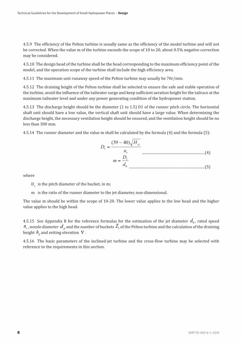
4.5.9 The efficiency of the Pelton turbine is usually same as the efficiency of the model turbine and will not be corrected. When the value m of the turbine exceeds the scope of 10 to 20, about 0.5% negative correction may be considered.
4.5.10 The design head of the turbine shall be the head corresponding to the maximum efficiency point of the model, and the operation scope of the turbine shall include the high efficiency area.
4.5.11 The maximum unit runaway speed of the Pelton turbine may usually be 70r/min.
4.5.12 The draining height of the Pelton turbine shall be selected to ensure the safe and stable operation of the turbine, avoid the influence of the tailwater surge and keep sufficient aeration height for the tailrace at the maximum tailwater level and under any power generating condition of the hydropower station.
4.5.13 The discharge height should be the diameter (1 to 1.5) D1 of the runner pitch circle. The horizontal shaft unit should have a low value, the vertical shaft unit should have a large value. When determining the discharge height, the necessary ventilation height should be ensured, and the ventilation height should be no less than 300 mm.
4.5.14 The runner diameter and the value m shall be calculated by the formula (4) and the formula (5):
r
sj
nH
D)40~39(
1 ....................................................................... (4)
0
1
dDm =
...................................................................................... (5)
where
D1 is the pitch diameter of the bucket, in m;
m is the ratio of the runner diameter to the jet diameter, non-dimensional.
The value m should be within the scope of 10-20. The lower value applies to the low head and the higher value applies to the high head.
4.5.15 See Appendix B for the reference formulas for the estimation of the jet diameter 0d , rated speed rn , nozzle diameter pd and the number of buckets 1Z of the Pelton turbine and the calculation of the draining
height ph and setting elevation .
4.5.16 The basic parameters of the inclined-jet turbine and the cross-flow turbine may be selected with reference to the requirements in this section.

SHP/TG 002-6-1: 2019
Part 6-1: Hydraulic Machinery and Turbine Generator
9
4.6 Calculation of the regulation guarantee of the unit4.6.1 Calculation of the regulation guarantee of the turbine shall be conducted according to the main electrical connection mode of the hydropower station, the power grid requirements, type and parameters of the water conveyance system of the hydropower station, the characteristics and parameters of the turbine generator units as well as the operating conditions.
4.6.2 As for the hydropower station with bifurcated penstocks, the maximum speed rising ratio of the units and the maximum pressure rising ratio at the end of the spiral casing shall be calculated according to the number of units connected to the main penstock and the main electrical connection mode, as well as the number of units that are able to simultaneously perform load shedding.
4.6.3 As for the hydropower station with a relatively simpler power generation and water conveyance system, the calculation of the regulation guarantee may be conducted by the empirical formula, and with the numerical method or the analytical method; as for the hydropower station with a complex water conveyance system, the calculation shall be made by computer simulation.
4.6.4 Axial-flow and through-flow turbine units should be equipped with a closing device with two gradients of closing rate to reduce the reverse hydraulic thrust and mitigate the influence of the turbine lifting.
4.6.5 The water flow inertia time constant Tw of the water conveyance system for the turbine without a pressure regulating facility shall not be more than 4s; the inertia time constant Ta of the reaction turbine unit shall not be less than 4s and the inertia time constant Ta for the impulse turbine unit shall not be less than 2s.The specific value T
w/Ta shall not be more than 0.4; if T
w/Ta is more than 0.4, the water diversion system
and unit stability calculation shall be performed in case of small fluctuations according to the actual situation.
4.6.6 When calculating the rising ratio of the rotating speed of the axial-flow and through-flow turbine units, it is necessary to include the influence of the inertia moment of the water flow; the calculation of the regulation guarantee shall include the pressure of the reverse water hammer.
4.6.7 In case of load shedding, the guarantee value of the maximum rising ratio of the rotating speed shall be selected according to the following different circumstances:
a) The guarantee value should be less than 50% when the proportion of the unit capacity to the total capacity of the electrical power system is relatively large or the unit has the frequency adjustment function;
b) The guarantee value should be less than 60% to 65% when the proportion of the unit capacity to the total capacity of the electrical power system is not large, or the unit has no frequency adjustment function;
c) The maximum rising ratio of the rotating speed of the through-flow turbine unit should be less than 65%;
d) The maximum rising ratio of the rotating speed of the impulse turbine unit should be less than 30%.
4.6.8 In case of load shedding, the guarantee value of the maximum pressure rising ratio at the end of the spiral casing (in front of the movable guide vane of the through-flow turbine unit) shall be selected as per the following circumstances:
a) The guarantee value should be 70% to 100% if the rated head is less than 20m;
b) The guarantee value should be 70% to 50% if the rated head is 20m to 40m;
c) The guarantee value should be 50% to 30% if the rated head is 40m to 100m;
d) The guarantee value should be 30% to 25% if the rated head is 100m to 300m;
e) The guarantee value should be less than 25% if the rated head is more than 300m.

Technical Guidelines for the Development of Small Hydropower Plants – Design
SHP/TG 002-6-1: 201910
4.6.9 When the unit load suddenly increases or decreases, the minimum pressure at the highest point of various sections along the entire length of the penstock shall not be less than 0.02MPa, and the negative pressure flow separation phenomenon shall not occur.
4.6.10 In case of load shedding, the maximum vacuum guarantee value at the entrance section of the draft tube shall not be more than 0.08MPa.
5 Generator
5.1 General requirements for generator type selection5.1.1 The type of generator shall be selected through technical and economic comparison mainly in accordance with the type and the parameters of the turbine as well as the requirements of the electrical power system, and in combination with the parameters such as the unit output determined during turbine type selection, the rotating speed, unit structure and layout form.
5.1.2 The type selection for the generator shall include the following contents:
a) Rated power(Pr)or rated apparent power(Sr) of the generator;
b) Rated voltage of the generator (Ur);
c) Rated speed (nr);
d) Rated frequency (fr);
e) Power factor (cosΦ);
f) Insulation grade;
g) Exciting mode;
h) Ventilation-cooling type of the generator;
i) Moment of inertia of the generator (GD2);
j) Estimation of the overall dimensions, weight and cost of the main components of the generator.
5.1.3 Main basis for the generator type selection:
a) Determine the power and rotating speed according to the turbine characteristics;
b) Determine the voltage and power factor according to the requirements of the electrical power system;
c) Determine the moment of inertia of the generator according to the calculation of the regulation guarantee of the hydropower station and the requirement of the electrical power system;
d) Determine the structural style of the generator according to the general situation.
5.2 Rated data and main parameter selection
5.2.1 Power
The generator power shall meet the following requirements:

SHP/TG 002-6-1: 2019
Part 6-1: Hydraulic Machinery and Turbine Generator
11
a) Relationship between the generator power and the turbine output:
1) Directly coupled unit: The rated power of the generator shall be equal to the rated output of the turbine multiplied by the generator efficiency;
2) Booster unit: The rated power of the generator shall be equal to the rated output of the turbine multiplied by the booster efficiency and by the generator efficiency.
b) Priority selection series (MW) of generator rated power:
0.5, 0.63, 0.8, 1.0, 1.25, 1.6, 2.0, 2.5, 3.2, 4.0, 5.0, 6.3, 8.0, 10.0
5.2.2 Voltage
The generator voltage shall meet the following requirements:
a) The requirements of the power grid of the country where the hydropower station is located.
b) The rated voltage shall be selected with consideration given to the value range of the rated current. The rated current shall be calculated by the formula (6):
cos3P1000I
r
rr
U=
............................................................................. (6)
where
Ir is the rated current, in amperes, in A;
Pr is the rated power, in megawatts, in MW;
Ur is the rated voltage, in volts, in V;
Cosφ is the power factor.
5.2.3 Power factor
The generator power factor shall meet the following requirements:
a) The rated power factor may lag 0.8 or 0.92 under the premise of meeting the requirements of the power grid;
b) Under rated power of the generator, the leading phase operation depth is allowed;
c) It is preferable to select a higher power factor value when the system permits, select a lower value when the hydropower station is close to the load centre and select a higher value when the transmission distance is great.

Technical Guidelines for the Development of Small Hydropower Plants – Design
SHP/TG 002-6-1: 201912
5.2.4 Synchronous speed
The generator synchronous speed shall meet the following requirements:
a) The rated synchronous speed of the generator shall be determined by the turbine type. It shall be calculated by the formula (7):
pfr60nr =
.................................................................................... (7)
where
nr is the rotating speed, in revolutions per minute, in r/min;
fr is the grid frequency, in Hz;
p is the number of pole pairs, 2p refers to the number of poles.
b) See Table 2 for the rotating speed of the conventional generator.
Table 2 Optional rotating speed for the synchronous generator
Number of poles 2p 4 6 8 10 12 14 16 (18) 20 (22) 24
nr (50Hz) 1500 1000 750 600 500 428.6 375 (333.3) 300 (272.7) 250
nr (60Hz) 1800 1200 900 720 600 514.3 450 (400) 360 (327.3) 300
Number of poles 2p (26) 28 30 32 (34) (36) 40 42 (44) 48 (50)
nr (50Hz) (230.8) 214.3 200 187.5 (176.5) (166.7) 150 142.9 (136.4) 125 (120)
nr (60Hz) (276.9) 257.1 240 225.0 (211.8) (200) 180 171.4 (163.6) 150 (144)
Number of poles 2p (52) 56 60 64 (66) (68) 70 (72) (78) 80 …
nr (50Hz) (115.4) 107.1 100 93.8 (90.9) (88.2) 85.7 (83.3) (76.9) 75 …
nr (60Hz) (138.5) 128.6 120 112.5 (109.1) (105.9) 102.9 (100) (92.3) 90 …
NOTE The rotating speeds not in parentheses are the recommended speeds; the rotating speeds in parentheses may be selected when necessary.
c) The coefficient for determination of the unit rotating speed shall be calculated by the formula (8); the coefficient for determination of the rotating speed shall meet the provisions of Table 3:
33
r )10(P rn nK = ............................................................................ (8)
where
Kn is the coefficient for determination of the rotating speed;
Pr is the rated power, in megawatt, in MW;
nr is the rated rotating speed, in revolutions per minute, in r/min.

SHP/TG 002-6-1: 2019
Part 6-1: Hydraulic Machinery and Turbine Generator
13
Table 3 Coefficient for determination of the rotating speed
Kn Kn≤0.01 0.01<Kn≤0.15 0.15<Kn≤2
2<Kn≤4
For the vertical type nr≥1000
For the horizontal type
nr≥1500
Kn>4
Rotating speed type Ultra-low speed Low speed Medium speed High speed Ultra-high speed
NOTE Neither the ultra-low speed nor the ultra-high
rotating speed is preferable for the units. It is necessary to perform the detailed technical
assessment when the ultra-high rotating speed has to be
selected.
5.2.5 Generator efficiency
The generator efficiency is positively correlated to the capacity and the rotating speed. At the rated power factor, the relationship between generator power and efficiency shall meet the requirements in Table 4.
Table 4 Relationship between output and efficiency
P (MW) 0.5<P≤1.0 1.0<P≤2.0 2.0<P≤5.0 5.0<P≤10
Efficiency (%) 90~94.5 90~95.5 92~96 93~96.5
5.2.6 Insulation grade
The insulation grade of the generator shall be Grade F. In the high altitude region or under special ambient air temperature, the temperature rise shall be corrected.
5.2.7 Moment of inertia
The moment of inertia shall meet the following requirements:
a) The mechanical time constant shall be calculated by the formula (9); the value range shall meet the provision of Table 5.
r232 P/)10(74.2 rmec nGDT = ...............................................................(9)
where
Tmec is the mechanical time constant;
GD2 is the moment of inertia, in t.m2;
nr is the rated speed, in revolutions per minute, in r/min;
Pr is the rated power, in megawatts, in MW.

Technical Guidelines for the Development of Small Hydropower Plants – Design
SHP/TG 002-6-1: 201914
Table 5 - Value range of Tmec
nr (r/min) 1500≤nr≤1000 750≤nr≤428.6 375≤nr≤200 nr<200
Tmec (s) 2~3.5 2.5~5 3~6 3.5~6.5
NOTE For the low-speed generator
and the high-power generator, it is allowed
to select the higher value in Table 5;
for the high-speed generator and low-
power generator, it is necessary to select the
lower value.
b) Method for the increasing moment of inertia:
1) A small amount of increase may be realized by increasing the weight of the rotor section with the larger rotary diameter;
2) A relatively greater amount of increase may be realized by increasing the size of the stator bracket;
3) For the horizontal unit, the moment of inertia may be increased by installing the additional flywheel according to the provisions in Table 6.
Table 6 - Moment of inertia increased by the additional flywheel
nr (r/min) 1500 1000 750 600、500 ≤428.6
GD2 (tm2) 0.2~0.7 0.3~1.4 0.5~3 0.75~4.5 1~6
NOTE Take the higher value for high-power generator and the smaller value for low-power generator.
d) Determination of the moment of inertia of the unit:
1) The moment of inertia for the unit shall be determined through calculation of the regulation guarantee of the hydraulic system of the hydropower station;
2) The value for the moment of inertia shall be reasonable; when the relatively higher moment of inertia is required, it is necessary to comprehensively consider the influences on generator dimension, appearance, efficiency, stability and weight.

SHP/TG 002-6-1: 2019
Part 6-1: Hydraulic Machinery and Turbine Generator
15
5.2.8 Short-circuit ratio
The value for the generator short-circuit ratio shall be in the range provided in Table 7.
Table 7 Value for the power factor and the short-circuit ratio
Power factor (lag) 0.8 0.85 0.9
Short-circuit ratio 0.9~1.0 0.95~1.05 1.0~1.1
NOTE Higher value is for the unit operating in the small power grid and for the low-speed unit, and the lower
value is for the high-speed unit.
5.3 Selection of the generator mechanical structure
5.3.1 Size of the stator bracket
The size of the stator bracket shall be selected as follows:
a) Common sizes include(mm): 740, 850, 990, 1180, 1430, 1730, 2150, 2600, 2860, 3250, 3300, 3600, 3850, 4250, 4650, 5000, 5500 and 6000;
b) The conventional size of the stator bracket may be estimated by the formula (10):
25.0
25.1r )P(1500 kdrn
D ...................................................................... (10)
where
D is the preliminarily- calculated diameter of the stator bracket size, in mm;
Pr is the rated power, in MW;
nr is the rated speed, in r/min;
Kd is the value coefficient, take 1.35 for ultralow speed, 1.4 for low speed and 1.5 for other speeds.
c) The size of the stator bracket of the vertical reaction turbine unit may be calculated by the formula (11):
P
DKD S 27.211
......................................................................... (11)
where
D1 is the runner diameter, in mm;
Ks is the take 1.35 for the axial-flow turbine and 1.45 for the Francis turbine;
2P is the number of poles of the generator.
d) The value D for the generator shall be estimated by the formula (10), another value D for the vertical reaction generator shall be estimated by the formula (11) as if the head cover is lifted out in its entirety from the inner circle of the core; the higher value shall be selected after comparison, and

Technical Guidelines for the Development of Small Hydropower Plants – Design
SHP/TG 002-6-1: 201916
then a similar size is selected;
e) It is necessary to select the smaller size for the horizontal unit to reduce the centre height of the unit and to improve the unit stability.
5.3.2 Bearings
There are mainly two bearing types, i.e. rolling bearing and sliding bearing:
a) Each generator shall be fitted with at least two bearings which shall be selected by the manufacturer according to the load condition.
b) Rolling bearing applies to the series of the horizontal generator with a bracket diameter of990 mm or smaller and the unit has two or three or four fulcrums, as well as the vertical generator with a bracket diameter of 1180 mm or smaller which does not sustain the weight of the rotary part and the axial hydraulic thrust of the turbine.
c) Sliding bearing applies to all the generators.
d) Except that the horizontal impulse unit is fitted with only two transverse bearings, the generator unit of the other types shall be fitted with at least one thrust bearing.
5.4 Generator auxiliary system
5.4.1 Ventilation-cooling system
The cooling mode of the generator is air cooling - the ventilation patterns mainly include closed recirculation, duct ventilation and open-type ventilation.
a) Closed recirculation: The hot air generated from the cooling of the generator is cooled in the air cooler, and then returned to the generator in a closed loop which applies to generators of all types. The closed-recirculation air cooler of the horizontal generator may be arranged in the turbine pit by the side or on the top of the generator.
b) Duct ventilation: Including the ordinary duct ventilation structure employing the direct axial air inlet mode and the closed-pipeline ventilation structure absorbing air from the turbine pit.
c) Open-type ventilation: Take air from the powerhouse to cool down the generator and then discharge the hot air directly in the powerhouse.
d) See Table 8 for the application scope of the different ventilation types.
Table 8 Application scope of the different ventilation types
Ventilation pattern Open-type ventilation Ordinary pipeline ventilation
Closed pipeline ventilation
Closed recirculation ventilation
Power Pr (MW) ~1.0 0.8~3.2 2.5~6.3 3.2~
NOTE Both ventilation patterns within the power range overlapping two columns may be selected for the generator.

SHP/TG 002-6-1: 2019
Part 6-1: Hydraulic Machinery and Turbine Generator
17
5.4.2 Braking device and jack system
The unit with the sliding bearing should be equipped with mechanical braking devices, while the impulse turbine unit with reverse jet braking should not be equipped with mechanical braking
a) The braking medium of the mechanical braking device should be0.7MPa compressed air or the pressure oil of the regulator after pressure reduction.
b) The brake shoes shall be made of non-asbestos environmentally-friendly material.
c) In the mechanical braking device for the vertical generator, the pressure oil shall be able to jack up the rotating part of the unit and the lock safely on any position - the brake with a piston diameter of more than 100mm shall employ the oil-gas separation structure.
5.4.3 Fire extinguishing apparatus
The fire extinguishing method shall be selected for the hydropower station and generators according to the local fire control specifications.
5.4.4 Dehumidification device
The generator shall determine whether to install the dehumidification device according to different environmental humidity and unit capacity. The dehumidification device may be electric the heater and the dehumidifier. In case of the electric heater, it is necessary to ensure that the air temperature in the turbine pit is 5K higher than the ambient temperature, meanwhile a local high temperature which might damage the insulation is unacceptable.
6 Turbine governing system
6.1 Basic principles for governing system type selection6.1.1 The governing system shall be able to reliably control the unit under all operating conditions and start/stop the machine in the time required by the calculation of the regulation guarantee. The governor parameters shall be decided by the turbine manufacturer, and have sufficient safety margins.
6.1.2 The operating capacity of the governor shall match with the turbine. The governor shall use the most advanced and latest technology, operate reliably, be convenient for maintenance and easily realize the automation of the hydropower station.
6.1.3 The unit which might operate in the isolated grid shall be equipped with the microprocessor-based automatic turbine control system for the convenience of ensuring the safety of the equipment in the hydropower station and the electrical safety of the users when the unit is disconnected from the system.
6.1.4 As for the small and miniature units without the frequency regulation task and with no need to guarantee the auxiliary power when the unit breaks down, it is allowed to select the electric actuator or the hydraulic actuator, but it is necessary to ensure that the unit could stop safely and reliably when it breaks down. As for the hydropower station without the DC operating power supply, the actuator selected shall have the emergency shutdown device acting in case of power failure.
6.1.5 As for the governor with the pressure regulating valve control function, the control of its pressure regulating valve shall employ the hydraulic-coordinated mechanism.

Technical Guidelines for the Development of Small Hydropower Plants – Design
SHP/TG 002-6-1: 201918
6.1.6 The governor should employ the structural style of the high oil pressure (10MPa and above) bladder type accumulator and be fitted with the external servomotor.
6.1.7 The governor shall satisfy all kinds of requirements for automatic regulation and remote control. It could be operated manually and meet the demands in the process of starting, stopping, emergency stopping, and the overhaul process of the unit.
6.2 Operating capacity of the governor6.2.1 The operating capacity of the governor shall be selected so that the unit could be reliably controlled under the maximum head and the maximum discharge and be started and stopped as per the time required by the calculation of the regulation guarantee. The operating capacity of the governor shall have sufficient reserve allowance.
6.2.2 The operating capacity of the control systems for the medium and small sized Francis and axial-flow fixed blade propeller turbine may be calculated by the formula (12):
1max DHKQA = ........................................................................ (12)
where
A is the operating capacity of servomotor, in N·m;
K is the coefficient, value range: 250 to 300;
Q is the rated discharge of unit, in cubic meters per second, in m3/s;
Hmax is the maximum head, in meters, in m;
D1 is the diameter of the turbine runner, in m.
6.2.3 See Appendix C for the reference formulas for the calculation of the operating capacity of the governing systems of the impulse turbine, Kaplan turbine, shaft-extension through-flow and bulb through-flow turbines.
6.3 Control system of governor6.3.1 The control system of the governor should employ the single microcomputer system and be connected with the PID structure in parallel.
6.3.2 The technologically advanced and latest hardware and supporting electronic components should be adopted, and the hardware should be the programmable logic controller (PLC) or the single chip, and the interface communicating with the monitoring system shall be equipped.
6.3.3 The control system of the governor shall have the following basic auxiliary functions: the frequency tracking (for fast synchronization), trouble detection and treatment, artificial dead band, non-disturbance manual automatic switchover, auxiliary test and partial fault-tolerance functions.

SHP/TG 002-6-1: 2019
Part 6-1: Hydraulic Machinery and Turbine Generator
19
7 Main valve of the turbine
7.1 Basic principles for the main valve type selection7.1.1 For the SHP stations that supply several turbines by a single penstock, the main valve should be set in front of each turbine in order to ensure that each unit can generate electricity separately, conduct maintenance separately and provide accident protection.
7.1.2For the unit water conveyance system of the dam toe hydropower station with the short penstock, or the low head unit water conveyance system of the runoff type hydropower station or the river bed type hydropower station, the intake or tailwater outlet has been equipped with the fast gate as the unit accident protection, so the main valve cannot be installed before the turbine.
7.2 Selection of the main valve7.2.1 The selection of the main valves for the hydraulic turbines should be based on comprehensive analysis of the technical, economic and operational safety and reliability, according to the head of the power station, the maximum transient pressure, the rated flow rate of the turbine, the diameter of the spiral case inlet and the sediment characteristics.
7.2.2 The selection of main valve shall include the following contents:
a) Main valve type;
b) Design pressure and nominal diameter of the main valve;
c) Operation mode of the main valve;
d) Sealing type of the main valve;
e) Type and diameter of the bypass valve;
f) Opening and closing time of the main valve.
7.2.3 Basic information for the type selection of the main valves:
a) The maximum static head and the maximum transient pressure at the main valve of the power station;
b) Rated flow rate of the turbine;
c) Spiral case inlet diameter;
d) The content and characteristics of the sediment passing through the machine;
e) Length of the diversion system and the emptying time.
Technical Guidelines for the Development of Small Hydropower Plants – Design
SHP/TG 002-6-1: 201920
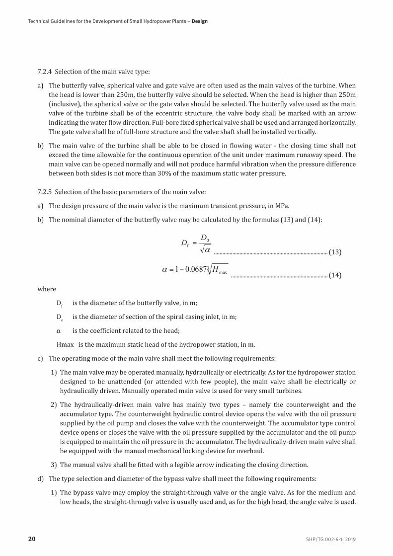
7.2.4 Selection of the main valve type:
a) The butterfly valve, spherical valve and gate valve are often used as the main valves of the turbine. When the head is lower than 250m, the butterfly valve should be selected. When the head is higher than 250m (inclusive), the spherical valve or the gate valve should be selected. The butterfly valve used as the main valve of the turbine shall be of the eccentric structure, the valve body shall be marked with an arrow indicating the water flow direction. Full-bore fixed spherical valve shall be used and arranged horizontally. The gate valve shall be of full-bore structure and the valve shaft shall be installed vertically.
b) The main valve of the turbine shall be able to be closed in flowing water - the closing time shall not exceed the time allowable for the continuous operation of the unit under maximum runaway speed. The main valve can be opened normally and will not produce harmful vibration when the pressure difference between both sides is not more than 30% of the maximum static water pressure.
7.2.5 Selection of the basic parameters of the main valve:
a) The design pressure of the main valve is the maximum transient pressure, in MPa.
b) The nominal diameter of the butterfly valve may be calculated by the formulas (13) and (14):
0f
DD =
................................................................................ (13)
3
max0687.01 H= .................................................................... (14)
where
Df is the diameter of the butterfly valve, in m;
Do is the diameter of section of the spiral casing inlet, in m;
α is the coefficient related to the head;
Hmax is the maximum static head of the hydropower station, in m.
c) The operating mode of the main valve shall meet the following requirements:
1) The main valve may be operated manually, hydraulically or electrically. As for the hydropower station designed to be unattended (or attended with few people), the main valve shall be electrically or hydraulically driven. Manually operated main valve is used for very small turbines.
2) The hydraulically-driven main valve has mainly two types – namely the counterweight and the accumulator type. The counterweight hydraulic control device opens the valve with the oil pressure supplied by the oil pump and closes the valve with the counterweight. The accumulator type control device opens or closes the valve with the oil pressure supplied by the accumulator and the oil pump is equipped to maintain the oil pressure in the accumulator. The hydraulically-driven main valve shall be equipped with the manual mechanical locking device for overhaul.
3) The manual valve shall be fitted with a legible arrow indicating the closing direction.
d) The type selection and diameter of the bypass valve shall meet the following requirements:
1) The bypass valve may employ the straight-through valve or the angle valve. As for the medium and low heads, the straight-through valve is usually used and, as for the high head, the angle valve is used.

SHP/TG 002-6-1: 2019
Part 6-1: Hydraulic Machinery and Turbine Generator
21
2) The discharge capacity of the bypass valve shall be greater than the water leakage of the guide vane - its nominal diameter shall not be less than 10% of the nominal diameter of the main valve.
3) As for the high sediment concentration and the relatively higher head, the diameter of the bypass valve may be preliminarily calculated by the formula (15):
sj
sjp H
QD )33.0~29.0(=
............................................................. (15)
where
Qsj is the design discharge of the turbine, in m3/s;
Hsj is the design head of the turbine, in m.
e) The adjustable scope of the opening and closing time of the main valve should be 60s to 120s. The closing time of the main valve in flowing water shall not exceed the allowable operating time of the unit at maximum runaway speed.
7.3 The seal type selection of the main valve
When the head is medium or low and the sediment concentration in the water flow is high, the rubber soft seal should be used; when the head is high and the sediment concentration is low, the metal hard seal should be used. The shaft end seal may employ the entire-loop solid rubber seal.
8 Auxiliary system
8.1 Technical water supply and the drainage systems8.1.1 The selection of the water source should be based on the requirements of the water consumption equipment for water volume, water pressure, water temperature and water quality, and the specific conditions of the power station. Water sources may be taken from reservoirs, penstock, power station tail water or other water sources.
8.1.2 The technical water supply mode shall be determined according to the head range of the hydropower station; when the minimum head is lower than 30m, the water should be supplied by pump; when the net head is 30m to 100m, the water should be supplied by automatic flowing or automatic flowing with pressure reduction; when the net head is higher than 100m, the water should be supplied by automatic flowing with pressure reduction and others.
8.1.3 The technical water supply system shall be able to be operated automatically.
8.1.4 The water for the main shaft seal of the turbine should be provided with the standby water source which could be put into use automatically.
8.1.5 When the water is supplied by pump, it is necessary to provide the standby water pump.
8.1.6 The technical water supply system shall be equipped with the water filter. When the water filter is filtering the dirt, the water supply for the system shall not be interrupted. The quality of the water used for

Technical Guidelines for the Development of Small Hydropower Plants – Design
SHP/TG 002-6-1: 201922
the bearing lubrication and main shaft sealing shall meet the requirements for cleanliness for the desired use.
8.1.7 The water drainage for unit overhaul (dewatering) and for leakage in the power plant should be realized with separate but interconnected drainage systems. Two drainage pumps shall be installed for the maintenance of the unit, and the total displacement shall be guaranteed to exclude the total displacement of one unit for maintenance within 4h to 6h. There shall be no less than two drainage pumps for the water collecting well in the plant, one of which is standby, and the drainage pump shall be automatically controlled according to the change in water level of the water collecting well.
8.1.8 The outdoor drainage system in the plant area shall be an independent system, which shall not feed water into the water-collecting well or the water-collecting gallery in the plant.
8.1.9 Power station leakage and drainage shall not be directly discharged into the river without treatment.
8.2 Oil system8.2.1 The hydropower station should be equipped with the independent turbine oil system, and equipped with oil handling and storage equipment.
8.2.2 Insulation oil system for the hydropower station may not be necessary.
8.2.3 The volume of the turbine oil tank shall meet the requirements for oil storage, oil replacement during overhaul and oil purification. The volume of the turbine oil tank should be 110% of the oil consumption of the unit with maximum capacity.
8.2.4 The oil treatment equipment shall include the oil pump and oil purification equipment. Their types, capacity and quantity shall be determined according to the oil consumption of the hydropower station.
8.2.5 A central oil service system should be established for the cascade hydropower stations or a group of hydropower stations. The central oil service system shall be equipped with the oil storage, oil treatment and oil purification equipment. The configuration of the oil system for the hydropower station equipped with central oil service system shall be simplified.
8.3 Compressed air system8.3.1 The medium pressure and low pressure compressed air system may be established in the powerhouse according to the requirement of the hydropower station.
8.3.2 The pressure of the medium pressure air compressor system for the inflation of the oil pressure supply unit shall be determined according to the rated operating pressure of the oil pressure supply unit; two air compressors shall be provided, one for use and one for standby and one air tank shall be provided. The volume of the air tank may be determined according to the air compensation for the pressure oil tank. The rated operating pressure of the air tank should be 0.2MPa to 0.3MPa higher than the rated operating pressure of the pressure oil tank. The air tank shall be fitted with the safety valve, pressure gauge and blow-down valve and the condensate removal arrangement.
8.3.3 The pressure of the low pressure air compressor system for the braking, overhaul and maintenance of the unit as well as the sealing of the shroud ring of the turbine main shaft and the sealing ring of the butterfly valve shall be 0.7MPa to 0.8Mpa; the braking air for the unit shall meet the following requirements:
a) The braking air system of the unit shall be equipped with the special air tank and the air supply pipeline for the braking air system of the unit;

SHP/TG 002-6-1: 2019
Part 6-1: Hydraulic Machinery and Turbine Generator
23
b) The total volume of the air tank for unit braking shall be determined according to the total air consumption of the units to be braked at the same time;
c) The capacity of the air compressor shall be determined as per the air consumption of the units to be braked at the same time and the time for resuming the operating pressure of the air tank. The time for resuming the operating pressure of the air tank may be10min to 15min;
d) The braking air of the unit shall be supplied with the standby air compressor or other standby air source in addition to supply from the air compressor.
8.4 Hydraulic monitoring system8.4.1 The hydraulic monitoring system shall meet the requirements for safe, reliable and economic operation and automatic control of the turbine generator.
8.4.2 The hydropower station should be provided with the conventional measurement items including the upstream water level, downstream water level, surge-chamber water level, hydropower station head, pressure difference between the front and back of the trashrack reservoir as well as the reservoir water temperature. The unit should be provided with pressure at the intake of the spiral casing, the head cover pressure, the pressure at the intake of the draft tube as well as the cooling water pressure of the unit, while the selective measurement items may be provided as well, such as the flow passing through the unit, the pressure fluctuation of the turbine, the unit efficiency, unit vibration, unit throw and the pressure (vacuum) in the draft tube.
8.4.3 The hydraulic monitoring system shall be designed and arranged in combination with the automatic monitoring system of the hydropower station for the purpose of the optimal generating by the hydropower station.
8.5 Selection of the lifting equipment8.5.1 The main powerhouse of the hydropower station shall be equipped with the crane or other lifting equipment. Single-trolley or double-trolley bridge cranes may be used. The type and rated lifting capacity of the crane shall be determined according to the total weight of the heaviest object to be lifted plus the lifting tools, and with reference to the standards for the crane series. The span of the crane may be selected according to the standard span for the crane and power station dimensions. The lifting height and speed of the crane shall meet the requirement for installation and overhaul.
8.5.2 The hydropower station having the GIS room shall be equipped with the crane for the installation and overhaul of the GIS room.
8.6 Heating and ventilation8.6.1 The heating and ventilation patterns of the hydropower station shall be determined according to the local meteorological conditions, the powerhouse type and the requirements of the production places for the air parameter and shall comply with the relevant provisions in the country.
8.6.2 The main machine hall of the surface powerhouse, the erection bay and the auxiliary powerhouse should employ natural ventilation. When the indoor air parameter requirements could not be met by natural ventilation, the combination of natural ventilation and mechanical ventilation, mechanical ventilation and local air conditioning may be adopted.

Technical Guidelines for the Development of Small Hydropower Plants – Design
SHP/TG 002-6-1: 201924
8.6.3 If the generator is ventilated through the pipeline, the hot air shall be led out of the powerhouse.
8.6.4 The oil tank room and the oil treatment room shall be equipped with separate ventilation systems. The air outlets of the ventilation system shall be 1.5m higher than the roof.
8.6.5 The ventilation rate of the GIS room shall be 8 times/hr., and the air inlet shall be set in the lower part of the room.
8.6.6 The heating device shall be equipped when the indoor temperature of the main and auxiliary powerhouses is lower than 5℃.
8.6.7 Necessary ventilation facilities shall be installed in the gallery at the bottom of the dam.
8.7 Allocation of maintenance equipment for the electro-mechanical equipment8.7.1 The turbine maintenance equipment shall be selected according to the overhaul work on the electromechanical equipment, the connectivity with nearby towns and the coordination and processing conditions of the outsourcing work.
8.7.2 The cascade hydropower stations or a group of hydropower stations should be provided with a central repair workshop.
8.8 Schematic diagrams of typical oil, air and water systemsSee Figures C.5, Figures C.6 and Figures C.7 for the schematic diagrams of typical oil, air and water systems.
9 Fire extinguishing system
9.1 Basic principle for the design of the fire extinguishing system9.1.1 Fire protection system of the power station and unit equipment should follow the fire protection standards of the country.
9.1.2 The fire hazards and fire resistance rating shall be classified for the buildings and structures in the hydropower station.
9.2 Technical requirements9.2.1 The fire lane in the plant area shall not be less than 4.0m in width and should be used as the access road as well. The dead-end of the fire lane shall be designed with a turnaround.
9.2.2 There shall be at least two evacuation exits for the powerhouse of the hydropower station. On the generator floor and the floors below, the distance from the farthest workplace indoors to the nearest evacuation exit on this floor shall not exceed 60m.
9.2.3 It is necessary to provide a 100% oil storage pit or a20% oil storage pit and a common oil storage tank for the main oil-immersed transformer with single oil capacity over 1000kg and the other oil filling equipment.
9.2.4 The power cables and the control cables shall be laid in layers. The cables laid in layers shall be separated with clapboards with fire endurance not less than 0.5h.

SHP/TG 002-6-1: 2019
Part 6-1: Hydraulic Machinery and Turbine Generator
25
9.2.5 Every 100m of cable tunnels and ditches should be equipped with a fire-proof partition. Closure and partition measures should be implemented for the through-wall.
9.2.6 The automatic fire extinguishing system such as water spray shall equip the generator with a unit capacity not less than 12.5MV·A and the indoor main oil-immersed transformer with a unit capacity not less than 12.5MV·A.
9.2.7 The powerhouse shall be equipped with smoke discharging facilities and these shall be combined with the ventilation system.
9.2.8 The fire water for the plant area may be supplied with natural water flows, the special fire water tank and fire water pump, and may be combined with the living and the generation water supply systems. The water supply quality, water pressure and water volume shall meet the requirements for firefighting water supply.
9.2.9 The firefighting apparatuses shall be powered as per the level-II load and employ the separate and fail safe power supply loop. The control equipment for the firefighting apparatus shall be installed in the central control room. When the water is supplied with the firefighting water pump, the starting device for the firefighting water pump shall be set in the firefighting cabinet.
9.2.10 The emergency lighting and evacuation indication signs shall be provided in the escape route in the powerhouse at all floors, staircases, exits and in the firefighting water pump house.
9.2.11 The automatic fire alarm shall be installed in the hydropower station.
10 Layout of the powerhouse
10.1 Basic principle for the layout of the powerhouseThe hydraulic machinery and the electrical equipment should be arranged in different areas. The length and width of the unit section of the main powerhouse shall be determined according to the dimensions of the unit as well as the passageway, governor, oil pressure supply unit, main valve and electrical panel/cabinet, and in combination with the requirements for the installation, overhaul, operation, transportation and civil engineering design. The width of the main powerhouse shall also meet the requirement for the dimensions of the components to be lifted by the crane and the dimensions of the main valve. The layout of the powerhouse shall be designed with full consideration given to the requirements for ecology and environmental protection.
10.2 Technical requirements10.2.1 The lifting height in the main powerhouse shall meet the following requirements:
a) The requirement for the integral lifting of the generator rotor together with the shaft;
b) The requirements for assembling the turbine and the shaft sleeve and for integral lifting;
c) The requirement to send the main transformer to the factory for overhaul if necessary;
d) The requirement to turn over the components like the water distributor for the bulb tubular unit;
e) The distance between components lifted by the crane and the fixed object shall not be less than 0.3m in the vertical direction nor be less than 0.4m in the horizontal direction.
Technical Guidelines for the Development of Small Hydropower Plants – Design
SHP/TG 002-6-1: 201926
10.2.2 The surface area of the erection bay shall be determined according to the demand for the expanded overhaul of one of the unit-main components of the unit shall be arranged within the working scope of the crane hook and meet the following requirements:
a) Requirement of the sequence for lifting large pieces in the installation and overhaul process;
b) Net distance between the large pieces of the unit as well as between big pieces and wall (column) or fixed equipment shall be 0.8m to 1.0m;
c) The requirement for vehicles coming into the plant for the loading and unloading of the components shall be met;
d) The turbine oil room may be set up in the powerhouse while the insulation oil tank maybe set up outside the powerhouse and the oil treatment room shall be arranged near the oil tank room;
e) Other auxiliary machinery shall be arranged for the convenience of the installation, operation, overhaul and maintenance of the equipment.

SHP/TG 002-6-1: 2019
Part 6-1: Hydraulic Machinery and Turbine Generator
27
Appendix A (Normative)
Reference formula for the basic parameter calculation for the reaction turbine
A.1 Calculation of the rated discharge
' 21 1r r rQ Q D H= .......................................................................(A.1)
where
Qr is the rated discharge, in m3/s;
Q'1r is the unit discharge under the rated working condition, in m3/s;
Hr is the rated head, in m;
D1 is the nominal diameter of the runner, in m;
A.2 Calculation of the draft height and determination for setting the elevation of the turbine
A.2.1 See formula (A.2) for the calculation of the draft height
10
900s mH K H
............................................................(A.2)
where
Hs is the draft height, in m;
Kσ is the ratio of device cavitation coefficient to model cavitation coefficient;
σm is the cavitation coefficient of the turbine model;
H is the turbine head, in m.
Usually it may be calculated as per rated head; for the minimum head of the axial-flow turbine as well as the maximum head and corresponding σm of the Francis turbine shall be verified.
A.2.2 See formula (A.3) for setting the elevation of the vertical-shaft Francis turbine.
0
2w s
bH
....................................................................(A.3)where
▽ is the setting elevation, in m;
▽w is the tailwater level, in m;
b0 is the guide vane height, in m.

Technical Guidelines for the Development of Small Hydropower Plants – Design
SHP/TG 002-6-1: 201928
A.2.3 See formula (A.4) for setting the elevation of the vertical-shaft axial-flow turbine.
1w sH xD ...................................................................(A.4)
where
x is the height efficiency of the axial-flow turbine.
A.2.4 See formula (A.5) for setting the elevation of the horizontal-shaft reaction turbine.
1
2w sDH
.......................................................................(A.5)
A.3 Reaction turbine efficiency and correction calculation
A.3.1 See formulas (A.6) and (A.7) for the calculation of the prototype turbine efficiency
△ MT ............................................................................(A.6)
maxmax MT △ .....................................................................(A.7)
where
M is the model turbine efficiency;
is the corrected value for turbine efficiency;
maxT is the maximum efficiency of the prototype turbine;
maxM is the maximum efficiency of the model turbine.
In addition to the calculation according to the reference formulas listed in A.3.2 to A.3.4 below, the efficiency correction of the turbine should also take into account the correction caused by the abnormal components and the process deviation between the prototype and the model turbines. When the diameter of the runner is less than 1 m, it should be negatively corrected.
A.3.2 For the first method for the turbine efficiency correction, see formulas (A.8) and (A.9).
Francis:
2.0
1
1max 1)1(
DDK M
M△ .......................................................(A.8)
Axial-flow:
1.02.0
1
1max 7.07.0)1(
P
MMM H
HD
DK △ ......................................(A.9)

SHP/TG 002-6-1: 2019
Part 6-1: Hydraulic Machinery and Turbine Generator
29
where
K is the coefficient, K=0.5-0.7 (low value is for the retrofitted unit and the high value is for the new unit);
D1m is the runner diameter of the model turbine, inm;
Hm is the test head of the model turbine, in m;
HP is the head of the prototype turbine, in m.
A.3.3 For the second method for the turbine efficiency correction, see formulas (A.10) and (A.11).
Calculation formula for the efficiency correction of the reaction turbine recommended in IEC60193:
16.016.0
ReRe
ReRe
up
uref
um
urefrefb △
.............................................. (A.10)
0. 16
1
Re 1Re
bopt mr ef
ur ef r ef
uopt m r ef
VV
.................................................... (A.11)
where
b△ is the corrected value converted from the model efficiency to the prototype efficiency;
δref is the corrected value converted from the nominal value to the prototype efficiency;
Reuref is the standard Reynolds number;
Reum is the model Reynolds number at the calculating point;
Reup is the prototype Reynolds number at the calculating point;
Reuoptm is the reynolds number at the optimum efficiency point of the model;
ηboptm is the optimum efficiency of the model;
Vref is the standard loss distribution coefficient (0.8 for the Kaplan turbine, 0.7 for the Fancis and the fixed blade propeller turbines).

Technical Guidelines for the Development of Small Hydropower Plants – Design
SHP/TG 002-6-1: 201930
A.3.4 The third method for the turbine efficiency correction
As for the existing model test curve, the model test data of the Reynolds number and the water temperature, the efficiency correction may be calculated by the formulas (A.12-14):
16.0
ReRe1)1(
up
ummboptmb V△
................................................. (A.12)
m optm r efV V V= = .................................................................... (A.13)
6107ReRe urefum .............................................................. (A.14)
where
Vm is the oss distribution coefficient of the model;
Voptm is the oss distribution coefficient at the optimum efficiency point of the model.
A.4 Calculation of the rated power
9. 81Tr r r TrN Q H ................................................................. (A.15)
where
NTr is the rated power of the turbine, in kW;
ηTr is the prototype turbine efficiency under rated condition.
A.5 Calculation of the maximum runaway speed The maximum runaway speed of the Francis or the fixed blade propeller turbine shall be determined according to the maximum head and the maximum unit speed. The maximum runaway speed of the Kaplan turbine shall be calculated under the condition that the coordination relationship is maintained; in case of any special requirements, it may be calculated on the assumption that the coordination relationship is broken.
max'max 1 max
1f f
Hn n
D
............................................................... (A.16)
where
nfmax is the maximum runaway speed, in r/min;
n’1fmax is the maximum unit runaway speed, in r/min;
Hmax is the maximum head, in m.

SHP/TG 002-6-1: 2019
Part 6-1: Hydraulic Machinery and Turbine Generator
31
A.6 Estimation of the axial hydraulic thrust
)(
4 max2
1 kNHDKP zz
............................................................. (A.17)
where
Pz is the is the axial hydraulic thrust, in kN;
Kz is the is the axial hydraulic thrust coefficient; to be obtained as per the relevant experimental parameters.

Technical Guidelines for the Development of Small Hydropower Plants – Design
SHP/TG 002-6-1: 201932
Appendix B (Normative)
Reference formula for the basic parameter calculation of the impulse turbine
B.1 Calculation of the jet diameter
0
0
545 s j
p sj
Qd
K Z H
............................................................... (B.1)
9. 81f
s js j T f
NQ
H
.................................................................... (B.2)
where
d0 is the jet diameter, in mm;
Qsj is the turbine discharge under the design condition, in m3/s;
Kp is the number of runners;
Z0 is the number of nozzles per runner;
ηT is the prototype turbine efficiency under the design condition;
ηf is the generator efficiency.
B.2 Calculation of the rated speed
1. 25 1. 25 1. 251
0 1 1
s s j s s j s s jr
Tr p
n H n H n Hn
N K Z N N
............................................... (B.3)
1
0
ss
p
nn
K Z=
........................................................................... (B.4)
1
0
Tr
p
NN
K Z=
............................................................................. (B.5)
where
ns is the specific speed of the turbine, in m·kW;
ns1 is the specific speed of the single nozzle, in m·kW;
N1 is the output of the single nozzle, in kW.

SHP/TG 002-6-1: 2019
Part 6-1: Hydraulic Machinery and Turbine Generator
33
B.3 Calculation of the runner diameter and value m
r
sj
nH
D)40~39(
1 .................................................................... (B.6)
0
1
dDm =
.................................................................................. (B.7)
where
D1 is the pitch diameter of the bucket, in m;
m is the ratio of the runner diameter to the jet diameter, non-dimensional.
For ensuring the relatively higher efficiency of the turbine, the value m should be within the range of 10 to 20. Low value applies to the low head while the high value applies to the high head.
B.4 Estimation of the nozzle diameter and the number of buckets
0)25.1~15.1( dd p = .................................................................... (B.8)
11
0
6. 67D
Zd
0 ........................................................................ (B.9)
where
dp is the nozzle diameter, in mm;
Z1 is the number of buckets.
B.5 Calculation of the draining heightB.5.1 The draining height refers to the height for the ensuring safe and stable operation of the Pelton turbine, avoiding surge in case of load variation, guaranteeing the ventilation and preventing the energy losses due to the vortex and flow splash in the tailrace.
B.5.2 When determining the draining height, it is necessary to ensure the necessary ventilation height which should not usually be less than 400mm.
B.5.3 Calculation of the draining height, see formula (B.10)
1)5.1~0.1( Dhp .................................................................... (B.10)
where
hp is the draining height, m; high value is for the vertical shaft unit and the low value is for the horizontal shaft unit.
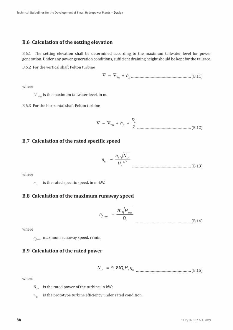
Technical Guidelines for the Development of Small Hydropower Plants – Design
SHP/TG 002-6-1: 201934
B.6 Calculation of the setting elevation
B.6.1 The setting elevation shall be determined according to the maximum tailwater level for power generation. Under any power generation conditions, sufficient draining height should be kept for the tailrace.
B.6.2 For the vertical shaft Pelton turbine
Wm ph ....................................................................... (B.11)
where
▽Wm is the maximum tailwater level, in m.
B.6.3 For the horizontal shaft Pelton turbine
1
2Wm p
Dh
................................................................ (B.12)
B.7 Calculation of the rated specific speed
5/ 4
r Trsr
r
n Nn
H
...................................................................... (B.13)
where
nsr is the rated specific speed, in m·kW.
B.8 Calculation of the maximum runaway speed
maxmax
1
70f
Hn
D
.................................................................... (B.14)
where
nfmax maximum runaway speed, r/min.
B.9 Calculation of the rated power
9. 81Tr r r TrN Q H ................................................................. (B.15)
where
NTr is the rated power of the turbine, in kW;
ηTr is the prototype turbine efficiency under rated condition.

SHP/TG 002-6-1: 2019
Part 6-1: Hydraulic Machinery and Turbine Generator
35
Appendix C (Normative)
Reference formula for the working capacity calculation of the governing system for some turbines
C.1 Impulse turbine
For the calculation of the operating capacity of the governing system for the impulse turbine, see formulas (C.1) and (C.2)
20 max
0( )6000
10nzd HA Z d +=
................................................................ (C.1)
3 3
011 10 xamedA d H Z= ................................................................. (C.2)where
Anz is the operating capacity of the needle servomotor, in N·m;
Z is the number of nozzles;
d0 is the jet diameter of the dependable discharge (or output), in cm;
Hmax is the maximum head, in m;
Ade is the operating capacity of the deflector servomotor, in N·m.
C.2 Kaplan turbine
For the calculation of the operating capacity of the governing system for the Kaplan turbine, see formulas (C.3) and (C.4)
Aga= K1 Q 1maxDH ....................................................................... (C.3)
Aru=K2φHmaxD13 ............................................................................ (C.4)
where
Aga is the operating capacity of the guide vane servomotor, in N·m;
K1 is the coefficient, value range: 250 to 300;
Q is the rated discharge of the unit, in m3/s;
Hmax is the maximum head, in m;
D1 is the turbine runner diameter, in m;
Aru is the operating capacity of the blade servomotor, in N·m;
K2 is the coefficient;
φ is the intersection angle between two extreme positions of the blade, in radian.

Technical Guidelines for the Development of Small Hydropower Plants – Design
SHP/TG 002-6-1: 201936
When the number of blades Z=4, K2=8.0; when Z=5, K2=8.5; when Z=6, K2=9.0.
C.3 Shaft-extension tubular turbine and the bulb tubular turbine
For calculation of the operating capacity of the governing systems for the shaft-extension tubular and the bulb tubular turbines, see formula (C.5)
max 1400A Q H D= ..................................................................... (C.5)
where
A is the operating capacity of the servomotor, in N·m;
Q is the rated discharge of the unit, in m3/s;
Hmax is the maximum head, in m;
D1 is the turbine runner diameter, in m.
C.4 Vertical unit layout
Key
1 turbine 2 generator
3 bridge crane 4 main valve
Figure C.1 - Transverse cross-section plan of the vertical unit power plant
1

SHP/TG 002-6-1: 2019
Part 6-1: Hydraulic Machinery and Turbine Generator
37
C.5 Horizontal unit layout
Key
1 turbine
2 generator
3 bridge crane
Figure C.2- Transverse cross-section plan of the horizontal unit power plant

Technical Guidelines for the Development of Small Hydropower Plants – Design
SHP/TG 002-6-1: 201938
C.6 Layout of the shaft-extension tubular type turbine unit
Key
1 bridge crane 2 turbine
3 speed increaser 4 generator
5 fish guiding box of tailwater
6 curtain type regulating weir
7 energy dissipation network
Figure C.3 - Layout of the shaft-extension tubular type turbine unit

SHP/TG 002-6-1: 2019
Part 6-1: Hydraulic Machinery and Turbine Generator
39
C.7 Layout of the bulb tubular turbine unit
Key
1 trash rack 2 bridge crane
3 generator 4 turbine
5 fast emergency gate
Figure C.4 - Layout of the Bulb Tubular Turbine Unit

Technical Guidelines for the Development of Small Hydropower Plants – Design
SHP/TG 002-6-1: 201940
C.8 Schematic diagram of the turbine oil system
Key
1 net oil tank
2 working tank
3 oilpurificationroom
Figure C.5 - Schematic diagram of the turbine oil system
C.9 Schematic diagram of the low pressure compressed air system
Figure C.6 - Schematic diagram of the low pressure compressed air system

SHP/TG 002-6-1: 2019
Part 6-1: Hydraulic Machinery and Turbine Generator
41
C.10 Schematic diagram of the technical water supply and drainage system
Figure C.7 - Schematic diagram of the technical water supply and drainage system


Vienna International CentreP.O. Box 300 · 1400 Vienna · Austria Tel.: (+43-1) 26026-oE-mail: [email protected]
INTERNATIONAL NETWORK ON SMALL HYDROPOWER
136 Nanshan RoadHangzhou · 310002 · P.R.ChinaTel.: (+86-571)87132793E-mail: [email protected]