part a. instruction sheet for lock service pack 7c3z...
TRANSCRIPT
PART A. INSTRUCTION SHEET FOR LOCK SERVICE PACK 7C3Z-1521990-A AND 8L3Z-1521990-A
NOTE: This Instruction Sheet is not an inspection document.
NOTE: All door-style locks:
A. Before removing the lock from the vehicle, note the direction at which the lever is pointing (forward, rearward, up or down). If the lock has been removed from the vehicle, note the lever and anti-theft switch wire (if so equipped) orientation with respect to the lock itself. Note also the offset direction (if applicable) of the lever. These notes will be helpful when putting the lever (and switch - if so equipped) on the new lock (refer to Figure 4).
B. Carefully remove the E-clip (G) and disassemble the lock lever from the back of the lock. Keep the E-clip (G), lever and anti-theft switch (if so equipped) in a secured place until the new lock has been built and is ready to be installed in the vehicle.
SK F85B-1521990-BB SHEET 1 OF 5
PART A. INSTRUCTION SHEET FOR LOCK SERVICEPACK 7C3Z-1521990-A AND 8L3Z-1521990-A
CPR 2007 FORD MOTOR COMPANYDEARBORN, MICHIGAN 48121
5-07
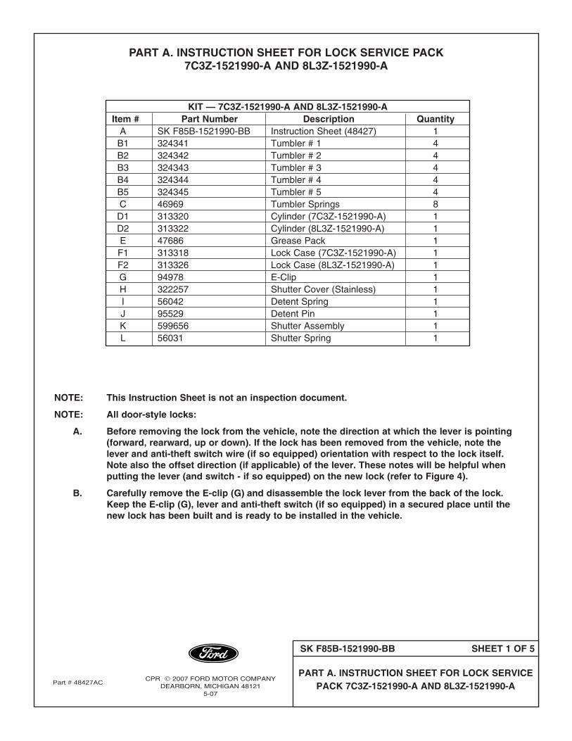
KIT — 7C3Z-1521990-A AND 8L3Z-1521990-AItem # Part Number Description Quantity
A SK F85B-1521990-BB Instruction Sheet (48427) 1B1 324341 Tumbler # 1 4B2 324342 Tumbler # 2 4B3 324343 Tumbler # 3 4B4 324344 Tumbler # 4 4B5 324345 Tumbler # 5 4C 46969 Tumbler Springs 8D1 313320 Cylinder (7C3Z-1521990-A) 1D2 313322 Cylinder (8L3Z-1521990-A) 1E 47686 Grease Pack 1F1 313318 Lock Case (7C3Z-1521990-A) 1F2 313326 Lock Case (8L3Z-1521990-A) 1G 94978 E-Clip 1H 322257 Shutter Cover (Stainless) 1I 56042 Detent Spring 1J 95529 Detent Pin 1K 599656 Shutter Assembly 1L 56031 Shutter Spring 1
Part # 48427AC
SERVICE PROCEDURE:
1. Determine the matching key cut depth at each key station, any of the following three methods may be used to determine the key cut depth at each key station.
1a. Use the OEM key code provided with the vehicle and look up the cut pattern in the key code table. (The selling dealer should have the key code or the customer may be able to provide it.) A key code table comes with the Rotunda Key Cutter, Part No. 011 00215.
1b. Use a "key decoder" to determine each cut height. A decoder may be included with the Rotunda Key Cutter, Part No. 011 00215 or can be ordered separately through Rotunda Part No. 011 RMT61. Equivalent decoders are commonly available through the locksmith industry. (A key decoder is a plate with an elongated slot corresponding to the different key cut heights.)
1c. Using the customer’s key, measure the key cut depth at each key station (refer to Figure 1).
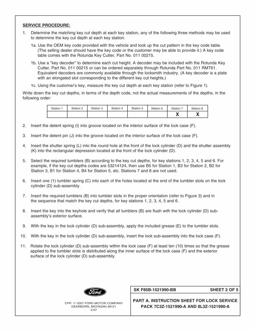
Write down the key cut depths, in terms of the depth code, not the actual measurements of the depths, in the following order:
2. Insert the detent spring (I) into groove located on the interior surface of the lock case (F).
3. Insert the detent pin (J) into the groove located on the interior surface of the lock case (F).
4. Insert the shutter spring (L) into the round hole at the front of the lock cylinder (D) and the shutter assembly (K) into the rectangular depression located at the front of the lock cylinder (D).
5. Select the required tumblers (B) according to the key cut depths, for key stations 1, 2, 3, 4, 5 and 6. For example, if the key cut depths codes are 53214124, then use B5 for Station 1, B3 for Station 2, B2 for Station 3, B1 for Station 4, B4 for Station 5, etc. Stations 7 and 8 are not used.
6. Insert one (1) tumbler spring (C) into each of the holes located at the end of the tumbler slots on the lock cylinder (D) sub-assembly.
7. Insert the required tumblers (B) into tumbler slots in the proper orientation (refer to Figure 3) and in the sequence that match the key cut depths, for key stations 1, 2, 3, 4, 5 and 6.
8. Insert the key into the keyhole and verify that all tumblers (B) are flush with the lock cylinder (D) sub-assembly’s exterior surface.
9. With the key in the lock cylinder (D) sub-assembly, apply the included grease (E) to the tumbler slots.
10. With the key in the lock cylinder (D) sub-assembly, insert the lock sub-assembly into the lock case (F).
11. Rotate the lock cylinder (D) sub-assembly within the lock case (F) at least ten (10) times so that the grease applied to the tumbler slots is distributed along the inner surface of the lock case (F) and the exterior surface of the lock cylinder (D) sub-assembly.
Station 1 Station 2 Station 3 Station 4 Station 5 Station 6 Station 7 Station 8
X X
SK F85B-1521990-BB SHEET 2 OF 5
PART A. INSTRUCTION SHEET FOR LOCK SERVICEPACK 7C3Z-1521990-A AND 8L3Z-1521990-A
CPR 2007 FORD MOTOR COMPANYDEARBORN, MICHIGAN 48121
5-07

12. Position the key in a vertical orientation and remove the key from the lock cylinder (D) sub-assembly while keeping the lock cylinder (D) sub-assembly within the lock case (F).
13. Place the shutter cover (H) over the lock case (F) and the lock cylinder (D). Use a pair of small pliers to gently bend the four (4) tabs on the shutter cover (H) inward toward the center of the lock case (F) to securethe lock cylinder (D) within the lock case (F).
14. Use the key to verify the lock rotates (smoothly) in both directions.
15. If the original lock contained a switch, be sure the rotary and the stationary parts of the anti-theft switch are properly aligned. Look at the side of the switch that is facing the lock. Locate the notch on the rotary part of the switch. This notch should be aligned with a thin groove located on the stationary part of the switch near the wires of the switch. Assemble the anti-theft switch on the back of the lock in the orientation recorded in steps A and B above. When assembling the anti-theft switch to the lock, do not rotate the rotary part of the anti-theft switch with respect the stationary part of the anti-theft switch or vice versa (refer to Figure 5).
16. Assemble the lever on to the back of the lock in the orientation recorded in steps A and B above and attach the E-clip (G) to retain the lever (and switch if so equipped) to the lock, refer to Figure 6 for E-clip alignment.
17. Use the key to verify the lock still rotates (smoothly) in both directions.
FIGURE 1
1 2 43 5 6 7 8
0.15 in
(3.90)mm
5 4 3 2 1
0.25 in
(6.44)mm
.0.20 in
(5.18)mm
0.30 in
(7.72)mm
0.35in
(9.00)mm
DEPTHCODES
.200 in
(5.08)mm
STOP
STATIONS
.292 in
(7.42)mm.384 in
(9.76)mm.476 in
(12.1)mm.586 in
(14.44)mm.661 in
(16.78)mm.753 in
(19.12)mm.845 in
(21.46)mm
SK F85B-1521990-BB SHEET 3 OF 5
PART A. INSTRUCTION SHEET FOR LOCK SERVICEPACK 7C3Z-1521990-A AND 8L3Z-1521990-A
CPR 2007 FORD MOTOR COMPANYDEARBORN, MICHIGAN 48121
5-07
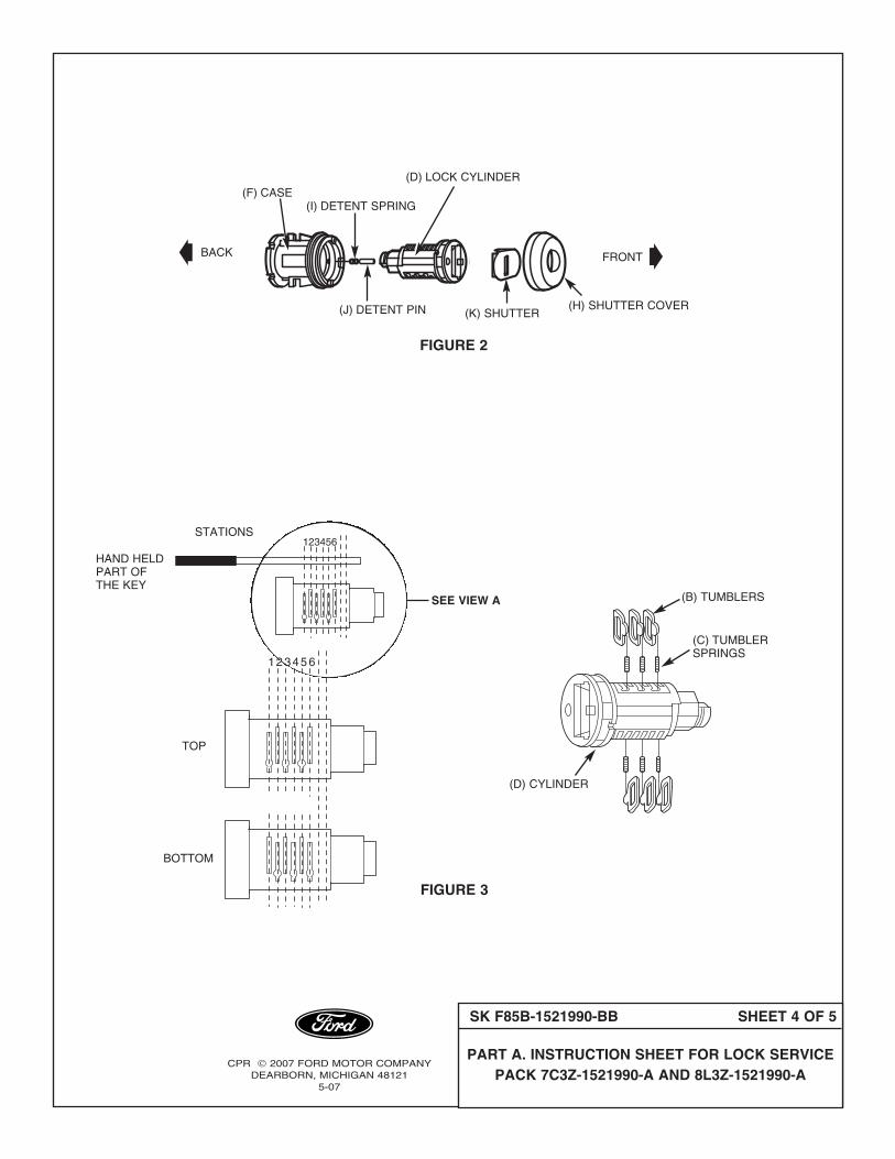
(F) CASE(I) DETENT SPRING
FIGURE 2
(D) LOCK CYLINDER
(J) DETENT PIN (K) SHUTTER(H) SHUTTER COVER
FRONTBACK
HAND HELDPART OFTHE KEY
TOP
BOTTOM
123456
SEE VIEW A
STATIONS
123456
(C) TUMBLERSPRINGS
(B) TUMBLERS
(D) CYLINDER
FIGURE 3
SK F85B-1521990-BB SHEET 4 OF 5
PART A. INSTRUCTION SHEET FOR LOCK SERVICEPACK 7C3Z-1521990-A AND 8L3Z-1521990-A
CPR 2007 FORD MOTOR COMPANYDEARBORN, MICHIGAN 48121
5-07
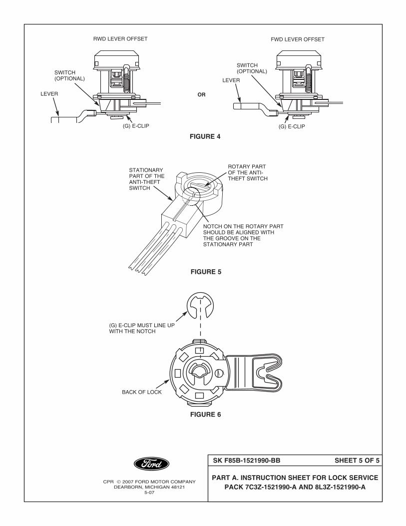
(G) E-CLIP MUST LINE UPWITH THE NOTCH
FIGURE 6
BACK OF LOCK
STATIONARYPART OF THEANTI-THEFTSWITCH
NOTCH ON THE ROTARY PARTSHOULD BE ALIGNED WITHTHE GROOVE ON THESTATIONARY PART
ROTARY PARTOF THE ANTI-THEFT SWITCH
FIGURE 5
RWD LEVER OFFSET
OR
SK F85B-1521990-BB SHEET 5 OF 5
PART A. INSTRUCTION SHEET FOR LOCK SERVICEPACK 7C3Z-1521990-A AND 8L3Z-1521990-A
CPR 2007 FORD MOTOR COMPANYDEARBORN, MICHIGAN 48121
5-07
SWITCH(OPTIONAL)
(G) E-CLIP (G) E-CLIP
LEVER
SWITCH(OPTIONAL)
FWD LEVER OFFSET
FIGURE 4
LEVER