part design - tolerance analysis
TRANSCRIPT

7/30/2019 PART DESIGN - Tolerance Analysis
http://slidepdf.com/reader/full/part-design-tolerance-analysis 1/15
Part Design
Outline
• Go over engineering specifications
• Functional requirements
• Form, fit and function
– Dimensioning
– Tolerancing
– Engineering drawings
– datum

7/30/2019 PART DESIGN - Tolerance Analysis
http://slidepdf.com/reader/full/part-design-tolerance-analysis 2/15
Materials
• Read Chapter 2 and 3 from Computer Aided
manufacturing
• Overview of engineering design
• Mechanical design representations
• Engineering drawing
• Geometric dimensioning and tolerancing
• CAD and Exchange Standards
THE DESIGN PROCESSProduct Engineering
Design ProcessHow can this be
accomplished?
1. Clarification of the task
2. Conceptual design
3. Embodiment design
4. Detailed design
Design Process
Off-road bicycle that ...
1. Conceptualization
2. Synthesis
3. Analysis
4. Evaluation
5. Representation
Functional requirement -> Design
Steps 1 & 2 Select material and properties, begin geometricmodeling (needs creativity, sketch is sufficient)
3 mathematical, engineering analysis4 simulation, cost, physical model5 formal drawing or modeling

7/30/2019 PART DESIGN - Tolerance Analysis
http://slidepdf.com/reader/full/part-design-tolerance-analysis 3/15
DESIGN REPRESENTATION
• Verbal
• Sketch
• Multi-view orthographic drawing (drafting)
• CAD drafting
• CAD 3D & surface model
• Solid model
• Feature based design
Design EngineeringRepresentation
Manufac-turing
Requirement of the representation method
• precisely convey the design concept
• easy to use
A FREE-HAND SKETCHOrthographic Projection

7/30/2019 PART DESIGN - Tolerance Analysis
http://slidepdf.com/reader/full/part-design-tolerance-analysis 4/15
A FORMAL 3-VIEW DRAWING
0.9444"
4 holes 1/4" dia
around 2" dia , first
hole at 45°
A
2.000 0.001
DESIGN DRAFTING
Third angle projection
P r o f i l e p l a n e
Y
Z
X
I I I
H o r i z o n t a l
F r o n t a l p l a n e
I
I V
I I
top
front
side
a
b c d ef
g
h i
j
Drafting in the third angle

7/30/2019 PART DESIGN - Tolerance Analysis
http://slidepdf.com/reader/full/part-design-tolerance-analysis 5/15
INTERPRETING A DRAWING
DESIGN DRAFTING
Partial view
Cut off view and auxiliary view
Provide more local details
A
2 . 0 0 0 0 . 0 0 1
A
A
A - A

7/30/2019 PART DESIGN - Tolerance Analysis
http://slidepdf.com/reader/full/part-design-tolerance-analysis 6/15
DIMENSIONING
Requirements
1. Unambiguous
2. Completeness
3. No redundancy0.83 ' 0.98 ' 1.22 '
3.03 '
Redundant dimensioning
0.83 ' 1.22 '
3.03 '
1.72 '
0.86 '
Adequate dimensioning
Incompletedimensioning
TOLERANCE
Dimensional tolerance - conventional
Geometric tolerance - modern
unilateral
bilateral
1.00 0.05+-
nominal dimension
tolerance
0.95+ 0.10- 0.00 1.05
+ 0.00- 0.10
1.00 0.05+-
0.95 - 1.05means a range

7/30/2019 PART DESIGN - Tolerance Analysis
http://slidepdf.com/reader/full/part-design-tolerance-analysis 7/15
TOLERANCE STACKING
"TOLERANCE IS ALWAYS ADDITIVE" why?
What is the expected dimension and tolerances?
d = 0.80 +1.00 + 1.20 = 3.00
t = ± (0.01 + 0.01 + 0.01) = ± 0.03
0.80 ' ±0.01 1.20 ' ±0.01
1.00 ' ±0.01
?
1. Check that the tolerance & dimension specifications arereasonable - for assembly.
2. Check there is no over or under specification.
TOLERANCE STACKING (ii)
What is the expected dimension and tolerances?
d = 3.00 - 0.80 - 1.20 = 1.00
t = ± (0.01 + 0.01 + 0.01) = ± 0.03
0.80 ' ±0.01 1.20 ' ±0.01
3.00 ' ±0.01
?

7/30/2019 PART DESIGN - Tolerance Analysis
http://slidepdf.com/reader/full/part-design-tolerance-analysis 8/15
TOLERANCE STACKING (iii)
Maximum x length = 3.01 - 0.79 - 1.19 = 1.03Minimum x length = 2.99 - 0.81 - 1.21 = 0.97
Therefore x = 1.00 ± 0.03
0.80 ' ±0.01 1.20 ' ±0.01
3.00 ' ±0.01
?
x
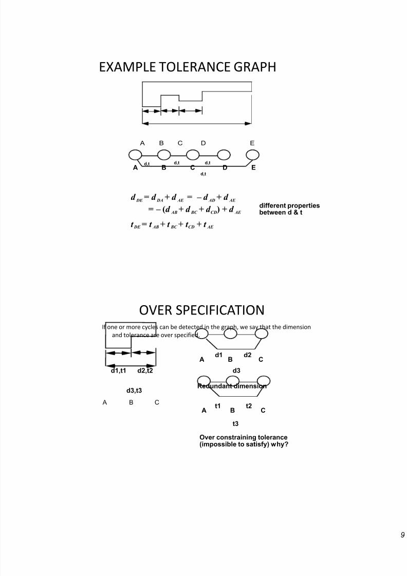
TOLERANCE GRAPH
G(N,d,t)
N: a set of reference lines, sequenced nodes
d: a set of dimensions, arcs
t: a set of tolerances, arcs
A B C D Ed,t d,t d,t
d,t
d : dimension between references i & j
t : tolerance between references i & jij
ij
Reference i is in front of reference j in the sequence.
7/30/2019 PART DESIGN - Tolerance Analysis
http://slidepdf.com/reader/full/part-design-tolerance-analysis 9/15
EXAMPLE TOLERANCE GRAPH
A B C D E
A B C D Ed,t d,t d,t
d,t
different propertiesbetween d & t
d DE =
d DA+
d AE =
– d AD+
d AE
= – (d AB
+ d BC
+ d CD) + d
AE
t DE = t AB+ t BC + t CD + t AE
OVER SPECIFICATIONIf one or more cycles can be detected in the graph, we say that the dimension
and tolerance are over specified.
A B C
A B C
A B C
d1 d2
d3d1,t1 d2,t2
d3,t3
t1 t2
t3
Redundant dimension
Over constraining tolerance(impossible to satisfy) why?

7/30/2019 PART DESIGN - Tolerance Analysis
http://slidepdf.com/reader/full/part-design-tolerance-analysis 10/15
UNDER SPECIFICATION
A B C D E
A B C D Ed1 d2
d3
C D is disconnected from therest of the graph.
No way to find dBC anddDE
When one or more nodes are disconnected from the graph, the
dimension or tolerance is under specified.
PROPERLY TOLERANCED
A B C D E
A B C D Ed,t d,t d,t
d,t
d DE
= d DA
+ d AE
= – d AD
+ d AE
= – (d AB
+ d BC
+ d CD) + d
AE
t DE = t AB+ t BC + t CD + t AE

7/30/2019 PART DESIGN - Tolerance Analysis
http://slidepdf.com/reader/full/part-design-tolerance-analysis 11/15
TOLERANCE ANALYSISFor two or three dimensional tolerance analysis:
i. Only dimensional tolerance
Do one dimension at a time.
Decompose into X,Y,Z, three one dimensional problems.
ii. with geometric tolerance
t r u e p o s i t i o n
d i a m e t e r & t o l e r a n c e
A circular tolerance zone, the size is influencedby the diameter of the hole. The shape of thehole is also defined by a geometric tolerance.
3-D GEOMETRIC TOLERANCE
PROBLEMS
± t
datum surfacedatum
surface
Referenceframe
perpendicularity

7/30/2019 PART DESIGN - Tolerance Analysis
http://slidepdf.com/reader/full/part-design-tolerance-analysis 12/15
TOLERANCE ASSIGNMENT
Tolerance is money
• Specify as large a tolerance as possible as long as functional and assemblyrequirements can be satisfied.
function
cost
Tolerance value
REASON OF HAVING TOLERANCE
• No manufacturing process is perfect.
• Nominal dimension (the "d" value) cannot be achieved exactly.
• Without tolerance - lose the control andas a consequence cause functional orassembly failure.

7/30/2019 PART DESIGN - Tolerance Analysis
http://slidepdf.com/reader/full/part-design-tolerance-analysis 13/15
EFFECTS OF TOLERANCE (I)
1. Functional constraintse.g.
d ± t
flow rate
Diameter of the tube affects the flow. What is the allowedflow rate variation (tolerance)?
EFFECTS OF TOLERANCE (II)
2. Assembly constraints
e.g. peg-in-a-hole dp
dh
How to maintain theclearance?
Compound fitting
The dimension of each segmentaffects others.

7/30/2019 PART DESIGN - Tolerance Analysis
http://slidepdf.com/reader/full/part-design-tolerance-analysis 14/15
RELATION BETWEEN
PRODUCT & PROCESS
TOLERANCES• Machine uses the locators as the
reference. The distances from themachine coordinate system to thelocators are known.
• The machining tolerance is measuredfrom the locators.
• In order to achieve the 0.01tolerances, the process tolerancemust be 0.005 or better.
• When multiple setups are used, thesetup error need to be taken into
consideration.
S e t u p
l o c a t o r s
± 0 . 0 0 5
± 0 . 0 0 5
± 0 . 0 0 5
Design specifications
Process tolerance
A
± 0 . 0 1 t o ler an c e s
SURFACE FINISH
w a v i n e s s w i d t h
r o u g h n e s s w i d t h
w a v i n e s s
r o u g h n e s s
63 0.010
0.005
0.002 - 2roughnessheight
waviness height
waviness width
roughness width cutoff default is 0.03" (ANSI Y14.36-1978)
roughness width
Lay
(m inch)
(inch)
63
Usuallysimplified:

7/30/2019 PART DESIGN - Tolerance Analysis
http://slidepdf.com/reader/full/part-design-tolerance-analysis 15/15
PROBLEMS WITH DIMENSIONAL
TOLERANCE ALONE
1 . 0 0 1
1 . 0 0 1 1 . 0 0 1
6 . 0 0
1 . 0 0 ± 0 . 0 0 1
6 . 0 0 ± 0 . 0 0 1
As designed:
As manufactured:
Will you accept the partat right?
Problem is the control of straightness.
How to eliminate theambiguity?
GEOMETRIC TOLERANCES
FORM
straightness
flatness
Circularity
cylindricity
ORIENTATION
perpendicularity
angularity
parallelism
LOCATION
concentricity
true position
symmetry
RUNOUTcircular runouttotal runout
PROFILEprofileprofile of a line
ANSI Y14.5M-1977 GD&T (ISO 1101, geometric tolerancing;ISO 5458 positional tolerancing; ISO 5459 datums;and others), ASME Y14.5 - 1994
Squareness
roundness