part i introduction to plasma technology for surface ... · pdf fileintroduction to plasma and...
TRANSCRIPT
1
Part IIntroduction to Plasma Technology for Surface Functionalization
Plasma Technology for Hyperfunctional Surfaces. Food, Biomedical and Textile Applications.Edited by Hubert Rauscher, Massimo Perucca, and Guy BuyleCopyright 2010 WILEY-VCH Verlag GmbH & Co. KGaA, WeinheimISBN: 978-3-527-32654-9

3
1Introduction to Plasma and Plasma TechnologyMassimo Perucca
1.1Plasma: the Fourth State of Matter
The term plasma was first used by Lewi Tonks and Irving Langmuir in 1929 [1] todescribe a collection of charged particles in their studies of oscillations in the innerregion of an electrical discharge. Later, the definition was broadened to definea state of matter (‘the fourth state of matter’) in which a significant number ofatom and/or molecules are electrically charged or ionized with the fundamentalcharacteristic of exhibiting a collective behavior due to the long-range Coulombinteractions.
A rough but comprehensive definition of plasma is that of an ensemble ofcharged, excited, and neutral species, including some or all of the following:electrons, positive and negative ions, atoms, molecules, radicals, and photons. Onaverage a plasma is electrically neutral, because any charge unbalance would resultin electric fields that would tend to move the charges in such way as to neutralizecharges of opposite sign.
It is estimated that more than 99.9% of the apparent universe is in the plasmastate: gaseous nebulae, interstellar gas [2], stars, including our sun [3–5], haveextremely high surface temperatures (from 2000 to 22 000 K) and they consistentirely of plasma. Our planet is not an exception to the presence of the plasmastate. The earth’s atmosphere (in the altitude range between 90 and 500 km, thethermosphere), is continuously bombarded by intense cosmic rays and solar windradiation and as a consequence its components become electrically charged speciesleading to the formation of an atmospheric shell, called the ‘ionosphere’ [6–9]. Thesolar UV radiation is almost completely absorbed by the ionosphere, producingthe electrically charged particles (especially electrons) which are deflected andfunneled by the magnetic field of the earth to the poles, which results in thenorthern hemisphere in the formation of spectacular ‘northern lights’ knownas Aurora Borealis [10]. Lightning developed during thunderstorms is a naturalplasma state as well. It is estimated that about 100 cloud–ground and cloud–cloudlightning strikes happen every second over the whole earth. Lightning is an intensetransient electric discharge of extremely long path-length (often many kilometers).
Plasma Technology for Hyperfunctional Surfaces. Food, Biomedical and Textile Applications.Edited by Hubert Rauscher, Massimo Perucca, and Guy BuyleCopyright 2010 WILEY-VCH Verlag GmbH & Co. KGaA, WeinheimISBN: 978-3-527-32654-9

4 1 Introduction to Plasma and Plasma Technology
Even though the mechanism of electric field development in clouds is incompletelyunderstood, it is suggested that this phenomenon is associated with the freezing ofwater. It was found that in the absence of ice the field build-up is slow and lightningis rare. Colliding ice particles are believed to generate electric-field growth andtheir separation under gravity probably contributes to the development of chargetransfer. The plasma state can be produced in laboratories and by raising theenergy content of matter regardless of the nature of the energy source. Thusplasmas can be generated by mechanical (close to adiabatic compression), thermal(electrically heated furnaces), chemical (exothermic reactions), radiant (high energyelectromagnetic and particle radiations, e.g., electron beams) and electromagnetic(arcs, coronas, direct current (DC), and radio frequency (RF), microwave (MW),electron cyclotron resonance (ECR) discharges) energies, and by the combinationof them, as in an explosion, in which mechanical and thermal energies are present.
1.2Historical Highlights
In the mid-nineteenth century the Czech medical scientist, Johannes Purkinje(1787–1869) used the Greek word plasma (which means ‘moldable substance’ or‘jelly’) to denote the clear fluid which remains after removal of all the corpuscularmaterial in blood.
Half a century later, in 1927, the Nobel prize winning American chemist IrvingLangmuir first used this term to describe an ionized gas. Langmuir was remindedof the way blood plasma carries red and white corpuscles by the way an electrifiedfluid carries electrons and ions.
Langmuir, along with his colleague Lewi Tonks, was investigating the physicsand chemistry of tungsten-filament lightbulbs, with a view to finding a way togreatly extend the lifetime of the filament. In the process, he developed the theoryof plasma sheaths, the boundary layers which form between ionized plasmasand solid surfaces. He also discovered that certain regions of a plasma dischargetube exhibit periodic variations of the electron density, which we nowadays termLangmuir waves. In the 1920s and 1930s a few isolated researchers began the studyof what is now called plasma physics. In the 1940s Hannes Alfven developed a theoryof hydromagnetic waves (now called Alfven waves) and proposed that these waveswould be important in astrophysical plasmas.
The creation of the hydrogen bomb generated a great deal of interest in controlledthermonuclear fusion as a possible power source for the future, since 1952. At first,this research was carried out secretly, and independently, by the United States, theSoviet Union, and Great Britain. But the ‘International conference on the peacefuluses of atomic energy’, held in Geneva in 1955 [11, 12], ratified the beginning ofthe studies on peaceful use of nuclear fusion. The constitution of the InternationalAtomic Energy Agency (IAEA) was almost contemporaneous (1957). Nowadays theagency works with its member states and multiple partners worldwide to promotesafe, secure, and peaceful nuclear technologies.

1.2 Historical Highlights 5
Fusion progress was slow through most of the 1960s, but by the end of thatdecade the empirically developed Russian tokamak configuration began producingplasmas with parameters far better than the lackluster results of the previous twodecades. By the 1970s and 1980s many tokamaks with progressively improvedperformance were constructed and at the end of the twentieth century fusionbreak-even had nearly been achieved in tokamaks [13].
In the 1970s a new application of plasma physics appeared, and has developedas critical technique for the fabrication of the tiny, complex integrated circuitsused in modern microelectronic devices. This application is now of great economicimportance for industry, indeed plasma processing has been an enabling technologyfor the broader applications of microelectronics which has led to the actualinformation and communication society with radical changes in worldwide livinghabits.
Plasma processing is a technology used in a large number of industries, andwhilst semiconductor device fabrication for computers is perhaps the best known,it is equally important in other sectors such as automotive, textile, food packaging,biomedical, polymers, and solar energy. A common theme in the applicationsis plasma treatment of surfaces. Plasma is an environmentally friendly processtechnology, producing an extremely low level of industrial by-products, especiallywhen compared to more traditional wet chemical treatments.
The principal applications of plasma treatments concern the processes thatinduce a limited and selected transformation of the outermost surface layer(nanometric scale).
Many fundamental processes take place during surface treatment of a material:the surface undergoes bombardment by fast electrons, ions, and free radicals,combined with the continued electromagnetic radiation emission in the UV-Visspectrum enhancing chemical-physical reactions in order to obtain the desiredfunctional and aspect properties.
Many properties and functionalities can be obtained by plasma treatment, andthey depend on the application: the plasma can be used to change the surfacewettability which can be changed from hydrophilic to hydrophobic and vice versa,to enhance the barrier characteristics, adhesion, dye-ability, printability, or theoleophobicity.
For example, plasma treatment of textile fabrics and yarns (see Chapter 6) isinvestigated as an alternative to wet chemical fabric treatment and pre-treatmentprocesses, for example, shrink resistance, water repellent finishing, or improvementof dye-ability, which tend to alter the mechanical properties of the fabric and areenvironmentally hazardous [14, 15].
In the food sector the application of plasma processing is interesting for manypurposes, in particular to provide barrier effects on homopolymeric packaging fortheir recyclability (see Chapter 8) or on biodegradable films (polylactic or starchbased compounds) to attain an extended shelf life by product preservation [16].Food processing also requires surfaces with enhanced functionalities in terms ofwear resistance, chemical inertness, controlled surface energy for adhesion control,and barriers against migration of heavy metals; whose properties are efficiently
6 1 Introduction to Plasma and Plasma Technology
achieved by deposition of coatings via plasma processing (see Chapter 9) or bysurface plasma treatment.
In the biomedical sector plasma technology is used for cold sterilization [17] ofinstruments and prostheses as well as many thermolabile materials used in thebiomedical technology sector for its particular advantages, including its moderateor negligible impact on substrate materials and use on nontoxic compounds). Lowpressure plasma (LPP) processing is also being investigated for the production ofnon-fouling surfaces to prevent the formation of biofilms with promising results(as detailed in Chapter 7)
1.3Plasma Fundamentals
Plasma is sometimes considered as the fourth state of matter, an expression thatwas first coined by Crooks in 1879 to describe the ionized medium created in agas discharge. Though this attribute can be somehow misleading, it highlightsthe unique feature of the plasma phase. The concept of the fourth state of matterresults from the idea that phase transitions occur by progressively providing energyto the matter, such as the one from the solid state to liquid up to the gas state.
A further ‘phase transition’ may be thought of as the one from the gas stateto the plasma state, even if this state is reached gradually by providing more andmore energy to the system. Therefore this process cannot be rigorously definedas a ‘phase transition’, because it lacks the signature of all real phase transitions:that is, an abrupt change (discontinuity) in the order parameter defining thethermodynamic phase.
Plasma can be seen as a particular ionized gas, which retains some uniquefeatures which distinguish it from an (ideal) gas. One of the main differencesis that plasma particles do interact, because of the electromagnetic couplingbetween charged particles and electric and magnetic collective perturbations whichconstitute the plasma itself.
Another important difference from an ideal gas is found in nonthermal plasmas(NTPs) in which quite different temperatures are associated with different species,due to the out-of-equilibrium thermodynamic regime. Indeed, in cold plasmas,neutrals and ions may be at ambient temperature whereas electrons may reachtemperatures close to 105 K. These plasma systems are of particular interestfor molecular processing and surface treatment, because cold plasmas oftenproduce ‘activated’ states of matter, capable of enhancing plasma–surface chemicalreactions and physical processing which cannot be achieved under thermodynamicequilibrium conditions. Therefore molecular and surface micro/nano-structurescan be fabricated by plasma processing in a way which is different from any otheravailable method.
In the following sections we do not claim to provide a rigorous derivation ofplasma fundamentals, which is available in several reference textbooks [18–21]; werather aim at providing a comprehensive overview of the basic concepts and to offer

1.3 Plasma Fundamentals 7
some helpful tools to better understand the plasma state and the different plasmaregimes determining the processing conditions for surface functionalization.
1.3.1Free Ideal Gas
An ideal gas is an ensemble of non-interacting rigid and negligible-size particles,each one undergoing frequent elastic scattering with other particles and with thephysical boundaries of the system. Real gases (containing many particles) may bedescribed in good approximation as ideal gases if they have a low density. Due tofrequent (elastic) collisions the ideal gases obey the Maxwell–Boltzmann velocitydistribution statistics, that is, the particles’ velocities (or energies) are distributedaccording to the statistical curve depicted in Figure 1.1, which is named after thetwo physicists Maxwell and Boltzmann.
For ideal gases the kinetic theory of gases provides a very good theoreticaldescription of microscopic and macroscopic physical state variables fully describingthe gas behavior. The kinetic theory of gases must be modified if there are stronginteractions or, more in general, where the conditions for an ideal gas no longerhold. For completeness sake we must say that strong interactions are indeed notthe only cause for a non-ideal gas regime. Quantum correlation responsible for gasdegeneracy can be another sufficient reason to give up the kinetic theory of gases.Anyway it is useful to recall the basis of the kinetic theory of gases in order tohave a starting point from which we can move toward a satisfactory description ofplasma physics.
If we think of the gas as an ensemble of N particles in a cubic box with volume Vand edge length l, a single particle moving along a box direction, say x, will undergoscattering by another particle or the box (perpendicular) surface. If the particlecollides onto the surface, its momentum change will be: �px = 2mvx, where m
0.001
0 500 1000
Speed (m/s)
1500 2000 2500
Pro
babi
lity
dens
ity (
s/m
)
0.002
0.003
0.0044He20Ne40Ar132Xe
Figure 1.1 Maxwell–Boltzman velocity distribution of somenoble gases for a given system temperature (298.15 K). Thex axis represents the velocity and the y axis reports the rel-ative particles probability density, that is, the fraction ofparticles per infinitesimal speed interval.

8 1 Introduction to Plasma and Plasma Technology
is the particle mass and vx its velocity. The force exerted by the particle will bethen: Fx = �px/�t. By considering the motion of the particle along the whole boxedge, we can consider the time during which momentum is changed as �t = l/vx.The force exerted by the i-th particle then results in: Fi = 2mv2
x/l. By summing upover all the particles (assumed to have the same mass) hitting the surface we mayestimate the overall force exerted on the surface, and remembering that pressureis p = F/A, we get (Equation 1.1):
Ftot =N∑
i=1
Fi =N∑
i=1
2mv2i
l; ptot =
N∑i=1
pi =N∑
i=1
2mv2i
l3=
N∑i=1
2mv2i
V(1.1)
In order to evaluate the overall pressure on each face we can consider the velocitycomponents along the three axes and assume that the particles’ velocities areequally distributed on average along each direction (Pascal principle). The totalpressure on the six faces of the box is then defined as:
p = N2m
⟨v2
⟩6V
= Nm
⟨v2
⟩3V
, with⟨v2⟩ = 1
N
N∑i=1
v2i (1.2)
or the average square velocity along one axis. By comparison of Equation (1.2),known as the Joule–Clausius formula, derived by microscopic considerations withthe ideal gas law pV = NkBT , (kB ≈ 1,381 · 10−23 J/K) valid for macroscopic systemquantities, it is possible to connect macroscopic physical variables with microscopicones. In particular the temperature reads T = m〈v2〉/(3 kB), and the total kineticenergy of the system is εtot = 1/2 Nm〈v2〉 = 3/2NkBT , whence we obtain the(average) single particle kinetic energy ε = 3/2 kBT (m being the particle mass, kB
the Boltzman constant, and N the number of particles).
1.3.2Interacting Gas
When considering a plasma – even if it is only partially ionized – it is necessaryto take into account long-range particle interactions in the ensemble. Indeed,electrically charged particles feel electric Coulomb forces whose range is longcompared with the characteristic scale length of the plasma. When chargedspecies are in motion they generate electric currents inducing internal magneticand electric fields which, in turn, interact with external fields. This dramaticallycomplicates the modeling of such a system, which is self-consistent througha strong coupling between its dynamics and the electromagnetic configuration.Although intrinsically complex, this coupling allows one to control to some extentthe dynamics of an ensemble of charged particles by biasing its collective behaviorwith external electromagnetic fields. A typical example of such plasma controllingby electromagnetic fields is its spatial confinement, which turns out to be veryuseful for technological applications and particularly for fusion.
Whereas an ideal gas (see Section 1.3.1) expands indefinitely in free space, aplasma can be temporarily confined in a small spatial region by applying suitable

1.3 Plasma Fundamentals 9
electromagnetic fields. In order to describe the plasma while taking into accountthe particle interactions a new theoretical framework is needed.
Electromagnetic interactions are described by the Maxwell equations. Relevantfields entering the equations are E and B, the electric and magnetic field in vacuum,respectively.
Here, vacuum does not mean that the equations hold only for the low pressureregime, but that the relevant fields are outside the medium, that is, the particleensemble. We do not need to describe fields inside the matter, because we areonly interested in gas dynamics. In order to properly describe the dynamics ofa population of many particles we need a statistical approach. The statisticalinformation can be encoded in the distribution function f(v, r, t) describing thepopulation time evolution in phase space. It depends on velocity (v, or momentump = mv), position (r), and time (t), and gives the statistical probability of theparticles’ velocity (momentum) and position at each time step. In other words,the distribution function contains the information on how many particles havemomentum p and position r. For short range particle interactions the Boltzmannequation provides a good model for plasma dynamics, describing the time evolutionof the distribution function of a particle population subject to external forces:
∂fα∂t
+ v · ∂fα∂r
+ ∂fα∂v
· Fm
= ∂fα∂t
∣∣∣∣coll
(1.3)
In Equation 1.3 quantities in bold character are regarded as vectors (or spacedifferential operators) and the subscript α refers to the different species to whichthe equation can apply, for example, electrons or ions. The first term is the freeevolution term, the second one represents the diffusion term from regions ofhigher density to lower density regions, the third one represents the drift term(from higher to lower density regions in reciprocal space). The right hand side(RHS) of the equation is the term taking into account the collisions betweenparticles. In a plasma the relevant force F is represented by the Lorentz force(Equation 1.4):
F = qα · (E + v × B) (1.4)
with qα the electrical charge of particle type α. Different from the kinetic theoryof ideal gases, the collisional term includes both elastic and inelastic scattering.Another important difference from the kinetic theory is that the Boltzmannequation holds also in the nonequilibrium regime. The Boltzmann equation iseasily derived from the Liouville theorem (Df /Dt = 0) as a consequence of matterand energy conservation, once the distribution function f is well defined.
Despite its intrinsic complexity due to the collective behavior of particles inplasma systems, some approximations of this collisional term have been proposed,leading to different forms of the Boltzmann transport equation which are valid inspecific plasma regimes.
For example, for fully ionized plasmas (e.g., in thermal plasmas), the suitablecollision term leads to the Fokker–Planck equation based on the fundamentalassumption that long range Coulomb interactions produce large angle deflections

10 1 Introduction to Plasma and Plasma Technology
of particle trajectories due to the rapid succession of multiple collisions with distantparticles. In the Fokker–Planck model the collision operator reads:
∂f
∂t
∣∣∣∣coll
=∑
i
∂
∂vi
⟨�vi
�t
⟩f (v, t) + 1
2
∑i,j
∂2
∂vi∂vj
[⟨�vi�vj
�t
⟩f (v, t)
](1.5)
In Equation 1.5 the < > symbols denote the average change in velocity momentsof the distribution function per time unit and the indexes i and j refer to the spacecoordinates. This form of the collisional term takes into account nonequilibriumthermodynamic behavior at first expansion order. The first term on the RHS takesinto account acceleration or slowing down of a group of particles (for instance dueto effects similar to friction). The second term on the RHS accounts for diffusioneffects due to spreading of the distribution function.
For partially or weakly ionized plasmas, which are of greater interest for industrialplasma processing, short range interaction of ionized plasma particles with theneutral background dominates the other mechanisms such as diffusion andconductivity and a suitable formal representation of the two-body collisionaloperator is provided by Equation 1.6:
∂fα∂t
∣∣∣∣coll
=∑
γ
nγ
∫dV
∫d�
dσ
d�|v − v1|
[fα(r, v′, t)fγ (r, v′
1, t) − fα(r, v, t)fr (r, v1, t)]
(1.6)
where primed velocities refer to velocities of scattered particles and v, v1 representvelocities of two particles approaching each other before scattering. d� is the solidangle element in velocity space, α and γ refer to the incident and target particlespecies and σ is the scattering cross-section, which quantifies the particles collisionprobability. However, the Boltzmann equation with the above collision operatoris practically intractable for its intrinsic complexity and nonlinearity. For weaklyionized plasmas simplifying assumptions, which yield more tractable equations arepossible, provided that we consider the time evolution of the distribution functionas mainly determined by:
• average fields of charged particles included in a self consistent form;• applied external electromagnetic fields, included in the Lorentz force (see
Equation 1.4);• collisions dominated by charged species with the neutral background.
The last condition assumes, contrary to the Fokker–Planck theory, that thecollision duration is much shorter than the time lap in-between two collisions.Along with the previous assumptions the Boltzmann transport equation may befurther simplified by using a mean-free-transit time (τ ). This τ is the average timebetween collisions and is independent on the particle velocity. Hence, the collisionintegral reduces to Equation (1.7):
∂f
∂t
∣∣∣∣coll
= fo − f (r, v, t)
τ (|�v|) ≈ fo − f (r, v, t)
τ(1.7)
1.3 Plasma Fundamentals 11
The modified Boltzmann equation (sometimes referred to as the Krook model),becomes
∂fα∂t
+ v∂fα∂r
+ qα
m(E + v × B)
∂fα∂v
= − fα(r, v, t)
τα
(1.8)
Equation 1.8 accounts for the distribution function fα evolution of the α-species(e.g., electrons, positive and negative ions) toward relaxation to the equilibriumdistribution on local scale, which should be chosen as a local Maxwellian distribu-tion function. Conservation of particles is assumed and the collision operator isconsidered as source or sink of particles. A final simplification named after Lorentzconsiders only the electrons as diffusing particles having collisions in a backgroundof heavy particles described by an equilibrium statistical distribution.
1.3.3The Plasma as a Fluid
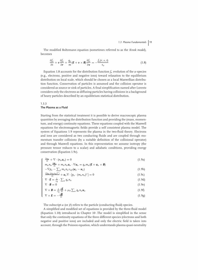
Starting from the statistical treatment it is possible to derive macroscopic plasmaquantities by averaging the distribution function and providing the (mass, momen-tum, and energy) continuity equations. These equations coupled with the Maxwellequations for electromagnetic fields provide a self consistent plasma model. Thesystem of Equations 1.9 represents the plasma in the two-fluid theory. Electronsand ions are considered as two conducting fluids and are coupled through mo-mentum transfer collisions (by a suitable definition of the collisional operator)and through Maxwell equations. In this representation we assume isotropy (thepressure tensor reduces to a scalar) and adiabatic conditions, providing energyconservation (Equation 1.9c).
∂nα∂t + ∇ · (nαuα) = 0 (1.9a)
mαnα∂uα∂t + mαnαuα · ∇uα = qαmα(E + uα × B)
−∇pα − ∑β mαnαναβ (uα − uα) (1.9b)
∂ [pα ·(mαnα )γ ]∂t + uα∇ · [pα · (mαnα)γ ] = 0 (1.9c)
∇ · E = 1ε0
· ∑α qαnα (1.9d)
∇ · B = 0 (1.9e)
∇ × B = 1ε0
∂E∂t + µ0
∑α qαnαuα (1.9f)
∇ × E = − ∂B∂t (1.9g)
The subscript α (or β) refers to the particle (conducting fluid) species.A simplified and modified set of equations is provided by the three-fluid model
(Equation 1.10) introduced in Chapter 10 .The model is simplified in the sensethat only the continuity equations of the three different species (electrons and bothnegative and positive ions) are included and only the electric field is taken intoaccount, through the Poisson equation, which understands plasma quasi-neutrality
12 1 Introduction to Plasma and Plasma Technology
conditions (negative and positive charges are balanced).
∂ne/∂t + divnewe = (νi − νa)ne + νdnn, (1.10a)
∂np/∂t + divnpwp = νine, (1.10b)
∂nn/∂t + divnnwn = νane − νdnn, (1.10c)
divE = e(np − ne − nn)/ε0, (1.10d)
In Equation 1.10 the indexes e, p, and n refer to electrons, positive, and negativeions, respectively, np, ne, and nn are the positive ion, electron, and negative ionnumber densities derived by the respective distribution functions integrated in thespace domain, wp, we, and wn their drift velocities, νi, νa, and νd are the ionization,attachment, and detachment frequencies, e is the electronic charge and ε0 is thepermittivity of free space. The electron drift velocity and kinetic coefficients areto be determined from solving the electron Boltzmann equation Equation 1.8 forα = e, the ion drift velocities are calculated using the known ion mobilities (seeEquation 1.29 below).
1.3.4Waves in Plasmas
Waves occurring in plasmas are described starting from the study of particledynamics either by a statistical approach or through the fluid models. Completedescription of waves in plasmas has been made extensively in dedicated works [22].Waves in cold plasmas of interest for technological applications are described byconsidering the plasma as a dispersive dielectric medium (accounting for plasmainhomogeneities and anisotropies) for which the appropriate dielectric tensor maybe defined.
Restricting our description of plasma waves relevant to applications described inthis book (see Chapter 2),we consider the case of magnetized plasmas, in which itis possible to describe the cold plasma as collisionless by taking into account onlyelectrons (ions and neutrals species are considered as an almost motionless particlebackground). For the sake of simplicity the external magnetic field is directed alongthe z axis and regarded as uniform and stationary (B0).
Assuming harmonic time dependence of time varying quantities (nα , pα,uα , E,B) in the two-fluid model (Equation 1.9), and combining the last two Maxwellequations (Equation 1.9f,g) by taking the curl of Equation 1.9g it is possible toderive the wave equation (Equation 1.11):
∇ × ∇ × E = ω2
c2ε · E (1.11)
where ε is represents the dielectric tensor. By taking the 3D Fourier transform ofthe same quantities with respect to space dependence, the vectorial Equation 1.12leading to the dispersion relation is obtained:
−k × k × E = ω2
c2ε · E (1.12)

1.3 Plasma Fundamentals 13
which can be written more explicitly as (Equation 1.13): k2
z 0 −kxkz
0 k2x + k2
z 0−kxkz 0 k2
x
Ex
Ey
Ez
= ω2
c2· ε⊥ −j · ε× 0
−j · ε× ε⊥ 00 0 ε=
Ex
Ey
Ez
(1.13)
The first term in parentheses of the RHS of Equation 1.13 is the explicit form ofthe plasma dielectric tensor.
For a non-collisional homogeneous plasma immersed in a steady uniformmagnetic field the resulting tensor components read:
ε⊥ = 1 − ω2pe
ω2 − ω2ce
ε× = ωce
ω
ω2pe
ω2 − ω2ce
(1.14)
ε= = 1 − ω2pe
ω2
with ωce = eB0/me is defined as the electron cyclotron frequency, which correspondsto the gyration frequency of electrons along the magnetic field lines, ωpe =(e2n/ε0 m)1/2 is the electron plasma frequency, corresponding to undriven smallamplitude electron oscillations. In the case of collisional plasma the plasmadielectric tensor components are given by (Equation 1.15):
ε⊥ = 1 − ω − jνm
ω
ω2pe
(ω − jνm)2 − ω2ce
ε× = ωce
ω
ω2pe
(ω − jνm)2 − ω2ce
(1.15)
ε= = 1 − ω2pe
ω(ω − jνm)
where νm represents the electron–neutral collision frequency. The last terms inEquation 1.14 and in Equation 1.15, corresponding to a direction parallel to themagnetic field (and transverse to the electric field) also represent the plasmadielectric constants in a nonmagnetized cold collisionless and collisional plasma,respectively. This simple case of transverse modes (k · E = 0) leads to the followingdispersion relation:
ω2 = ω2p,e + c2 k2 (1.16)
Equation 1.16 for the dielectric permittivity exhibits a phenomenon called cut-off .Cut-off occurs when ε goes to zero. That is, when (Equation 1.17)
ω2 = ω2p,e = e2ne
ε0me(1.17)
which corresponds to the critical electron density nc = meε0ω2/e2. For MWs with
a frequency of f = 2.45 GHz, (see Chapters 2 and 8) wave reflection occurs at thecritical electron density nc = 7.5 × 10¹⁶m−3. This is quite crucial for MW-generated
14 1 Introduction to Plasma and Plasma Technology
plasmas in which a MW source may produce a plasma with a maximum electrondensity equal to nc.
1.3.5Relevant Parameters that Characterize the State of Plasma
From the above theoretical framework it is possible to nail down some usefulphysical quantities and parameters which help in characterizing the plasma stateand different plasma regimes.
In particular, for systems in thermodynamic equilibrium such as high tempera-ture plasmas (thermal plasmas) a plasma temperature may be defined starting fromthe particle velocity (Maxwell) distribution. However also nonequilibrium plasmascan be described by parameters provided that there is local equilibrium, or that atleast the equilibrium within each particle species is maintained. This means that itis possible to define different equilibrium regimes for each plasma species even ifthe whole system is not in equilibrium. In this case different temperatures may bedefined for different particle populations, for cold plasmas typically electrons, ions,and neutrals. Thermal equilibrium within each species is due to the inefficientcollisions among different particle populations. In this regime mutual collisionsamong species (e.g., electron–ion or electron–neutral) do not lead to significantenergy losses (or gains) for any of the species involved in the interactions but colli-sions among particles of the same species are efficient in terms of energy exchange,providing fast thermalization and attainment of the equilibrium regime. A typicalcase is that in which electron, ion, and neutral temperatures may be definedseparately. For each plasma species assumed to be in thermodynamic equilibriuma Maxwell distribution is associated in velocity space (obtained by integrating theparticle distribution function over Euclidian space) and the selected plasma speciestemperature is related to the average kinetic energy of the particles derived fromtheir velocity distribution function second order momentum; therefore ion (i) andelectron (e) temperatures are defined as: Ti = m〈v2
i 〉/(3 kB) and Te = m〈v2e 〉/(3 kB).
Other characteristic physical parameters in space and time (frequency) domainsare useful to characterize plasmas and for their classification.
The Debye length (λD) represents the distance over which the electric field of eachcharge carrier (usually electrons) is screened, representing the interaction range ofsingle charged particles. It is given by Equation 1.18:
λD =√
ε0 kBTe
nee2(1.18)
where ne, Te, and e are the electron density, temperature, and charge(e = 1,602 · 10−19 C), respectively, kB the Boltzmann constant, and ε0 the vacuumelectric permeability (ε0 = 8,859 · 10−12F/m).
If non-negligible size particles are considered, another useful parameter of gasdynamics is the so-called mean free path, representing the average distance traveledby particles in rectilinear motion between subsequent collisions within the gas box(see the free ideal gas model of Section. 1.3.1). Where d is the classical particle
1.3 Plasma Fundamentals 15
diameter, T and p the gas temperature and pressure, the mean free path is evaluatedby (Equation 1.19):
λ = kBT√2πd2p
(1.19)
The plasma parameter (g) is a nondimensional parameter defined through theDebye length and the plasma (equilibrium) density: it is the measure of the numberof particles present in a Debye sphere (Equation 1.20):
g = 1
n0(λD)3(1.20)
The plasma parameter has to be small for a many body system to be treated inthe so-called ‘plasma approximation’. This means that the average potential energyof a particle is much less than its kinetic energy. Departure from this limit impliesthat the particles interaction energy to becomes more relevant and that the plasmamay not be treated as an ideal gas (this holds typically in the case of highly chargedparticles density per Debye sphere).
The thermal De Broglie wavelength � is the average particle de Broglie lengthdefined as Equation 1.21:
� =√
h2
2πmkBT(1.21)
where h is the Plank constant (h ≈ 6.626 × 10⁻³⁴ Js). To consider the plasma as aclassical system the following relations must be satisfied: � 3√n0 ;� e2/(kBT),where the last term on the RHS in the two relations are the mean spacing amongplasma particles and the distance of closest approach in Coulomb interactions,respectively. If the first inequality is violated, the binary collision among nearneighbor particles can no longer be treated classically. If the second approximationrelation does not hold, the system cannot be described by the Maxwell–Boltzmannstatistics, since degeneracy occurs and a quantum statistics has to be adopted,either Fermi–Dirac (fermion gas) or Bose–Einstein (boson gas).
Concerning the frequency domain, the plasma frequency may be defined as:
ωp,α =√
nαq2α
ε0 mα
(1.22)
When Equation (1.22) concerns the electron species (α = e, where here qe
represents the electron charge) the electron plasma frequency is the rate of electronfree oscillations (seen as a non-collisional plasma slab) over a background of almoststeady still positive ions, when the system is perturbed by a small amplitude electricimpulse. The plasma frequency may also be seen as a measure of the electrondensity and it is the parameter that influences the transmission (or damping) ofspecified frequency external electromagnetic waves. A similar quantity may bedefined for ions when α = i and qi = Ze is the total ion charge, providing the ionplasma frequency.
16 1 Introduction to Plasma and Plasma Technology
In magnetized low density plasmas charged particle motion is characterized byspinning around the magnetic field lines, and the ion and electron gyrofrequency isdefined as Equation (1.23):
ωc,α = qαB
mα
(1.23)
where B denotes the intensity of the magnetic field. For α = e and α = i the electronand ion gyrofrequencies are defined, respectively. Due to the electron-to-mass ratioand to typical reactor dimensions, in plasma processing the electron gyrofrequencyis of great interest, for example, in ECR plasmas (see Chapters 2 and 8). Thecorresponding gyration radius or gyroradius can be written as Equation (1.24):
rc = v⊥,α
|ωc,α| (1.24)
where v⊥,α represents the particle(s) of type-α speed component perpendicular tothe magnetic field.
Regarding characteristic velocity parameters, it is worth mentioning the driftvelocity of the guiding center of particles gyrating around magnetic field lines. TheE × B drift velocity is due to the presence of perpendicular components of electricand magnetic fields in the plasma (Equation 1.25):
vExB = E × BB2
(1.25)
The E × B drift motion is of particular importance, for example, in the confine-ment of secondary electrons in magnetron sputtering sources as well as for the con-trol of the arc spot on arc- physical vapor deposition (PVD) targets (see Chapter 2).
Considering electrostatic waves in plasmas the adiabatic electron sound speedaccounts for the propagation of waves in plasma parallel to the electric field (whichis possible in plasma but not in vacuum or in a conventional dielectric material) dueto an exchange between thermal and electric energy (γ being the ratio of specificheats in Equation 1.26):
ce,γ =√
γ kBTe
me(1.26)
In magnetized plasmas the Alfven velocity represents the phase speed of trans-verse waves produced by oscillation of ions through a perpendicular magnetic fieldwhose exerted force acts as a restoring force (Equation 1.27):
vA = Bõ0n0 mi
= ωc,i
ωp,i· c (1.27)
where ni and mi are the ion number density and mass, B is the magnetic fieldstrength, µ0 the vacuum magnetic permeability, and c the speed of light.
Regarding the transport parameters, when assuming only electron-neutral col-lisions and for low electric field frequencies (e.g., low frequency electric fieldperturbations) the plasma resistivity is defined as Equation (1.28):
ρ = mevm,e
nee2= vm,e
ε0ω2p
(1.28)

1.4 Classification of Technological Plasmas 17
where vm,e is the electron collision frequency, ne is the electron density, ωp isplasma frequency, me is the electron mass. For kinetic transport the mobility (µ)and diffusion coefficients (D) of the species α through a background of neutral(steady) particles are given by Equation (1.29):
µα = qα
mανm,α; Dα = kTα
mανm,α(1.29)
where Tα and νmα are the species temperature and collision frequency with neutrals.Another kinetic transport parameter relevant for electrically driven plasmas is the
ambipolar diffusion coefficient (Equation 1.30) accounting for the diffusion processinduced by the presence of static electric field:
DA = µiDe + µeDi
µi + µe(1.30)
where the subscripts i and e refer to ion and electron species, respectively. Formagnetically driven and magnetized plasmas electron diffusion perpendicular tothe magnetic field are described by the relative directional mobility and diffusioncoefficients (Equation 1.31):
µ⊥ = µe
1 + (ωc,e/υm,e)2; Dα = kTe
mανm,e· 1
1 + (ωc,e/υm,e)2(1.31)
Finally, we report Loschmidt’s number, corresponding to the particle numberdensity at standard pressure and temperature: n0 ≈ 2.6868 × 1025 m−3, useful togauge the variety of plasma densities in LPPs such as encountered in PVD or plasmaenhanced chemical vapor deposition (PECVD) reactors. In atmospheric pressureplasma (APP) regimes, examples are plasma jets, dielectric barrier discharge (DBD),or plasma coronas.
1.4Classification of Technological Plasmas
A first broad classification of plasmas may be done in terms of their thermodynamicproperties: thermal plasmas (TPs) and non thermal plasmas (NTPs) also regarded asplasmas in thermodynamic equilibrium and nonequilibrium plasmas, respectively.The first class includes high pressure hot plasmas characterized by pressures (p)exceeding 103 Pa with high electron temperatures (Te) in the order of 104 K andhigher. In these systems the collision frequency among different plasma speciesis efficient: the collision frequency is high with respect to the particles transittime on the plasma scale length and allows the electrons to lose energy infavor of the ion species, providing thermalization of different particle species tothe thermodynamic equilibrium temperature. The energy equipartition principleholds and energy content is evenly distributed among vibration, rotational, andtranslation energies. The ionization degree (number of ions over total plasmaparticles) is close or equal to 100%.

18 1 Introduction to Plasma and Plasma Technology
On the contrary cold NTPs are in a thermodynamic nonequilibrium state in whichit is sometimes possible to define different temperatures for the different plasmaspecies. The typical situation in plasma processing is to find relatively hot electronswith temperatures of the order of 104 K (Te ∼ 104K) and cold ions and neutrals,often found at almost ambient temperature (Ti ∼ Tn ∼ 104K). Nonthermal coldplasmas are associated with low degrees of ionization in the range 10−4 –10−1.
1.4.1Hot (Thermal) Plasmas and Their Applications
Hot plasmas, such as electrical arcs, plasma jets of rocket engines, plasmasgenerated by thermonuclear reactions, and so on, have an extremely high energycontent, which induces fragmentation of all organic molecules to atomic levels.As a consequence, these plasmas can only be used to generate extremely highcaloric energy or to modify thermally stable inorganic materials (metals, metaloxides, etc.). The thermal plasma is obtained by generating an arc discharge in agas submitted to electric fields of varied frequency. The bundle of gas ionized atvery high temperature is able to remove, fuse or to thermally modify a material.The bundle can be compared to a tool, it is easily controllable and not in directcontact with the treated surface. The applications of thermal plasmas depend ontemperature, gaseous reagents and tiny particles injected into the plasma (plasmaspraying, synthesis) or exposed to plasma in the form of ‘bulk materials’ (fusionand refining in metallurgy).
The potential applications of thermal plasma processing technology cover awide range of activities, such as the extraction of metals, the refining/alloyingof metals/alloys, the synthesis of fine ceramic powders, spray coatings, and theconsolidation and destruction of hazardous waste. In particular cases the thermalplasma finds applications in complicated chemical processes, for instance fastquenching chemistry or synthesis of nanoparticles.
In metal melting and remelting, the plasma is used primarily as an effectivesource of process heat, making use of the anode heat transfer characteristics ofan arc between a cathode and the metal. The relatively long characteristic processtimes (from 0.1 second to minutes) reduce the importance of instability effects.In plasma cutting and welding, the use of a plasma is more economical thanusing a laser or an electron beam which may provide higher power flux densities.New approaches are driven by improvement of the product quality and processreliability. Examples are the expanded use of pulsing the weld current and ofsensors for feedback control in automated welding.
Plasma sprayed coating has evolved extensively during the last 20 years, exceptfor the basic design of the plasma gun (nozzle), which has not been changed sig-nificantly. The essential part of the gun is the nozzle that consists of a cone-shapedcathode located within a cylindrical anode, which usually extends beyond thecathode. Reactive or inert gases or mixtures of them traversing the space locatedbetween the electrodes are ‘instantly’ ionized and as a result the plasma state isgenerated. For coating purposes, powders can be injected into the plasma jet at

1.4 Classification of Technological Plasmas 19
desired locations relative to the nozzle to control the caloric energy absorptionof the materials for deposition and the pathways of the plasma-borne particlesand droplets. The coating particles (powders) introduced into the jet are instantlymolten and the resulting droplets are deposited and cooled on the target surfacesusually leading to strongly bound – though porous – coatings. In plasma wastetreatment, the major advantages of using thermal plasmas are the fast heating rates,the high processing temperatures allowing the formation of stable vitrified slugs,and the low off-gas flow rates. Off-gas cleaning is a major economic factor in anywaste processing installation, and the costs scale down with increasing gas flows.The major issue is the economics of the specific process, and all new developmentshave been directed toward improving the economics either by combining plasmaprocesses with conventional incinerators to make use of the heating value of thewastes, or by using the waste heat to obtain a useful co-product.
1.4.2Cold (Nonthermal) Plasmas and Their Applications
In common perception, plasmas are hot gases that emit light and conduct electricity.Indeed, plasmas often contain energetic electrons (at E ∼= 1 eV = 1.1604 × 10⁴K orhigher) that in turn transfer their energy to neutral molecules and excite radiatingtransitions. However, not all plasmas are hot. Cold plasmas, including low-pressureDC and RF discharges (silent discharges), discharges from fluorescent (e.g., neon)illuminating tubes, DBDs may be found both at low pressure or atmosphericpressure. Cold LPPs for surface processing are found in the range between10−6 and 1 Pa, with a typical Debye length, corresponding to the electromagneticscreening distance, of 10−5 m, much less than the typical plasma scale length inthe order of 10−1 –1 m. Cold LPPs have neutrals densities between 10−5n0 and10−2n0(n0, being the Loschmidt number, as defined in Section 1.3.3), while coldAPPs such as DBDs are characterized by electron number densities of the order ofn0 with an energy range of 1–10 eV.
Electrons, which are small and light particles, cannot heat the large and heavymolecules very efficiently, so in many cases the background gas remains almostat room temperature. In such nonequilibrium systems (often called nonthermalplasmas or cold plasmas), the complex plasma chemistry is driven by electrons.They perform ionization, necessary to sustain the plasma; in addition, they areresponsible for atomic/molecular excitation, dissociation, and production of rad-icals and metastable molecular states. The result is an active gaseous mediumthat can be safely used without thermal damage to the surrounding materials.Such exceptional nonequilibrium chemistry is the base of plasma applications inlighting technology, exhaust gas treatment, and material processing. There areseveral methods to generate cold plasmas. When charged particles are in the mi-nority, heating of neutral molecules is limited. This leads to diffuse plasmas wherethe fraction of ionized species is below 10−7n0 and pressures reach 103 Pa. Theeffect of low pressure is double: in a rare gas ionization events are scarce, whichkeeps the charge density low. Moreover, the frequency of elastic collisions between

20 1 Introduction to Plasma and Plasma Technology
electrons and atoms/molecules is low, so electrons do not have much chance toconvey their energy to the gas. LPPs are of great value in fundamental researchas well as in plasma technology, but they have many serious drawbacks. Theseplasmas must be maintained in massive vacuum reactors, in which the chemistryis optimally controlled, but their operation is costly due to long pump down times,energy requirement, as well as the reactor maintenance burden. The access forobservation or sample treatment is limited, and there are limitations for the ma-terials to be treated because of degassing problems. Therefore, one of the recenttrends focuses on developing new plasma sources, which operate at atmosphericpressure, and target to retain the properties of low-pressure media. Also theseapproaches are characterized by positive features such as substrate accessibility,high throughput, continuous or semi-continuous processing, but limitations arealso found in the shapes of substrate to be treated, less precise control of plasmachemistry due to plasma pollution, different physical and chemical regimes posinglimitations to surface processing such as to plasma polymerization of high boilingpoint precursors.
NTPs may be generated for processing purposes by using different principleswhere the energy input comes from diverse sources.
In micro-plasmas gas heating occurs in the plasma volume, and the energy iscarried away by thermal diffusion/convection to the outside. If the plasma has asmall volume and a relatively large surface, gas heating is limited.
Coronas are gas discharges where the electrode geometry controls and confinesthe ionization processes of gases in a high-field ionization environment, in theabsence of insulating surfaces or when the dielectric surfaces are far away from thedischarge zone. Corona discharges are often called negative, positive, bipolar, AC, DC,or high frequency (HF) coronas, according to the polarity of the stressed electrodes,to whether one or both positive and/or negative ions are involved into the currentconduction, and to the nature of the driving field. What makes corona dischargesunique in comparison to other plasmas is the presence of a large low field drift re-gion located between the ionization zone and the passive (low field) electrode. Ionsand electrons penetrating the drift space will undergo neutralization, excitation,and recombination reactions involving both electrons and neutral and chargedmolecular and atomic species. However, because of multiple inelastic collision pro-cesses in atmospheric pressure environments the charged active species escapingfrom the ionization zone (electrons, ions) will have energies lower than the ion-ization energies, and as a consequence, neutral chemistry (free radical chemistry)will characterize the drift region. According to various electrode configurations,point-to-plane, wire-cylinder, and wire-to-plane corona discharges can be identified.
Dielectric barrier discharges. These plasmas are typically generated betweenparallel metal plates, which are covered by a thin layer of dielectric or highly resistivematerial. Usually they are driven by a HF electric current (in the kHz range), butit is also possible to obtain a DBD by simple transformation of 50 Hz/220 Vnetwork voltage to about 10 kV to 40 kHz electric input. The dielectric layer playsan important role in suppressing the current (sparking due to streamers): thecathode/anode layer is charged by incoming positive ions/electrons, which reduces
1.4 Classification of Technological Plasmas 21
the electric field and hinders charge transport toward the electrode. DBDs havetypically low ionization degrees and currents in the order of mA. Besides, theelectrode plates are quite large (∼0.1 m2, in some cases with a large aspect ratioof 10 : 1) and the distance between them usually does not exceed the millimeterrange. Thus, DBD has a large surface-to-volume ratio, which promotes diffusionlosses and maintains a low gas temperature (at most a few tens of degrees abovethe ambient). The only serious drawback of a DBD is its limited flexibility. Sincethe distance between the plates must be kept small, treatment of large and irregular(3D) samples is impossible, at least with conventional planar electrodes.
In electron cyclotron resonance ion sources (ECRISs), the plasma is confined ina special magnetic field configuration where an axial magnetic field is producedby, for example, two solenoid coils (magnetic mirror). Superimposed is a radialmagnetic field usually produced by a permanent multipole magnet. This geometryleads to a minimum-B-structure, that is, from the geometrical middle the magneticfield increases in all directions. Electrons confined in that magnetic field gyratearound the magnetic field lines with the cyclotron frequency (ωc,e). The microwaveenergy is radiated into the plasma and electrons can be heated resonantly whenthe microwave frequency equals the cyclotron frequency. Every time an electronpasses the resonance region it can gain 1–2 keV energy. Electrons from ECRIScan have energies up to several kiloelectronvolts and therefore a good magneticplasma confinement is required. Ions are not accelerated due to their high massand are confined electrostatically by the space charge of the plasma electrons. Whenelectrons leave the plasma through the loss cone of the magnetic mirror, ions canfollow and can then be extracted from the ion source by applying a high voltage. Themaximum obtainable charge state depends on the confinement time of the ions andon the energy of the plasma electrons. These can be varied by tuning the ion sourceparameters like gas pressure, microwave power, magnetic field strength, and so on.
Microwave plasmas are sustained by microwave energy dissipated into thereaction media by coaxial cables or by waveguides in the case of higher powers.The physical dimensions of coaxial cables (cross-sections) and waveguides areselected according to the microwave frequency. Most materials efficiently absorbor reflect microwaves, and as a result microwave energy cannot be transportedusing conventional cables. Microwave discharges are more difficult to sustainunder low-pressure conditions (<103 Pa). In a collisionless condition the energygained by an electron during one cycle is too small to produce ionization. Incollisional plasmas at constant power density and electric field, the average (RF)microwave power transferred from the driving field has a maximum value whenthe collision frequency equals the driving frequency. The absorption of microwavepower depends on the collision frequency of the electrons which is controlled by theatomic and molecular species. At comparable plasma parameters, RF dischargesmost often fill the entire reactor, whose dimensions are usually smaller than thewavelength of the RF field (13.56 MHz corresponds roughly to 22 m). Microwaveplasmas exhibit a strong peaking in field intensity at the coupling to the microwavecavity that diminishes gradually with increasing distance from the coupling, ratherthan being deposited throughout the discharge.

22 1 Introduction to Plasma and Plasma Technology
1.5Reactive Plasmas
In this section we particularly focus on the reactivity of NTPs and the capabilityof promoting plasma–chemical reactions through intermediate steps in a way toexploit the plasma state as a very efficient environment as compared to conventionalconditions where chemical reactions usually take place. The free electric charges –electrons and ions – make a plasma electrically conductive, internally interactiveand strongly responsive to electromagnetic fields. Plasma is widely used in practice,in particular for surface processing, and NTPs offer three major features that areattractive for industrial applications:
• The temperature of at least some plasma components and the energy density cansignificantly exceed those in conventional chemical technologies (e.g., energeticelectrons), abating the activation energy thresholds.
• Plasmas are able to produce very high concentrations of energetic and chemicallyactive species (electrons, ions, atoms and radicals, excited and metastable states,and photons with different wavelengths which can interact with the processingsurface).
• Cold plasmas are far from thermodynamic equilibrium, providing extremelyhigh concentrations of the chemically active species while keeping the bulktemperature as low as room temperature, thus not affecting the properties ofmaterial to be treated other than the ones of the functionalized surface.
These plasma features allow significant intensification of traditional chemicalprocesses, a dramatic increase of their efficiency and often successful promotionof chemical reactions which in conventional chemistry would require significantenergy input and the use of additional chemical compounds such as catalysts.Moreover, plasma treatments are by definition dry processing methods, thusavoiding the use of water and solvents, minimizing emissions and the overallenvironmental burden, as discussed in detail in Chapter 12.
1.5.1Elementary Plasma–Chemical Reactions
To reach the required degree of reactivity in a plasma not all particles need to beionized; a common condition in plasma chemistry is that the gases are only partiallyionized. The ionization degree in the conventional plasma-chemical systems spansa range of seven orders of magnitude (10−7 –10−14). When the ionization degree isclose to unity, such a plasma is called completely ionized plasma, which is often thecase in high temperature thermal plasmas. When the ionization degree is low, theplasma is called weakly ionized plasma, which is the main focus of plasma chemistryin the present context.
The total yield of the plasma–chemical processes is due to synergistic contri-butions of numerous different elementary reactions taking place simultaneouslyin a discharge system. The sequence of transformations of the initial chemical

1.5 Reactive Plasmas 23
substances and electric energy into products and thermal energy is usually referredto as the mechanism of the plasma–chemical process. Elementary reaction ratesare determined by the microkinetic characteristics of individual reactive collisions(like, for example, collision cross-sections, i.e., elementary reaction probabilities)as well as by relevant kinetic distribution functions (see Section 1.3), like theelectron energy distribution function (EEDF) and ion energy distribution function(IEDF), respectively defined generically as fα in the previous sections, and by otherdistribution functions such as that of excited molecular states. Formally reactionsrates (k) are calculated by means of the reaction cross-sections and interactingparticle speeds as Equation (1.32):
k = 〈v · σ 〉 (1.32)
where the <.> symbol stands for an averaged quantity over the distributionfunction and σ is the reaction cross-section, while v is the relative velocities of thereacting particles.
Indeed, the elementary reaction rate is actually the result of integration of thereactive collision cross-section over the relevant distribution function and it ischaracterized by the energy or excitation state of the reactant.
The key process to sustain the plasma discharge and therefore to allowplasma-chemical reactions is ionization, which means conversion of neutral atomsor molecules into electrons and positive ions. Thus, ionization is the first processesto be considered.
In quasi-neutral plasmas, typically employed in surface processing, the numberdensity of electron and positive ions species are comparable or equal (ne ≈ ni)in case of high electron affinity of heavy particle species negative ions are alsoeffectively formed and give rise to ‘electronegative’ plasmas. Mainly responsiblefor ionization are inelastic effective collisions. Therefore we dwell briefly on aquantitative description of collision phenomena principles and dynamics to get themain understanding of these processes.
Due to continuous impact of natural energetic cosmic rays on the neutralgas some free electrons are continuously generated and always available. Whenexternal (intense) electric fields are applied, an ionization avalanche process isstarted, providing more and more available free electrons. The latter are the firstspecies gaining kinetic energy from electric fields, because of their low massand high mobility with respect to other species such as ions. Those energeticfree electrons transfer energy to all other plasma components, providing energyfor ionization, excitation, dissociation, and other plasma chemical processes. Therates of such processes depend on how many electrons have enough energy todo the job. This can be quantitatively described by means of the EEDF, whichis the probability density f (ε) for an electron for having an energy ε. The EEDFstrongly depends on the applied electric field and the gas composition in theplasma (especially in nonthermal discharges) and often can be very far from theequilibrium distribution.
24 1 Introduction to Plasma and Plasma Technology
1.5.2Elastic Scattering and Inelastic Thomson Scattering: Ionization Cross-section
Electron–electron, electron–ion, and ion–ion scattering processes are so-calledCoulomb collisions. Their cross-sections are quite high with respect to those ofcollision with neutral partners, but they are much less frequent in a discharge witha low degree of ionization. An important feature of Coulomb collisions is the strongdependence of their cross-section on the kinetic energy of the colliding particles.This can be demonstrated by a simple analysis, where two particles (considered asrigid spheres) have the same charge and, for the sake of simplicity, one collisionpartner is considered to be at rest. A scattering event takes place if the Coulombinteraction energy (U ∼ q2/b, where b is the impact parameter) is comparable tothe kinetic energy ε of a moving particle. Then, the impact parameter b ∼ q2/ε andthe ionization reaction cross action σ can be estimated as σ = πb2, in the classicalhard spheres approximation.
In order to sustain a plasma and to provide its chemical reactivity, continuousionization is necessary. Electron collisions with the background neutral speciesand ions provide the mechanism to determine these conditions when collisions aresaid to be non-elastic and a certain amount of collisional energy is spent to directlyionize or excite and subsequently ionize the molecules.
Starting with the Rutherford formula for differential cross-section from (clas-sical) collision particle dynamics it is possible to derive the Thomson ionizationcross-section:
σiz(ε) = π
(e2
4πε0
)2 1
ε
(1
εiz− 1
ε
)(1.33)
Equation 1.33 is valid for ε > εiz and for ε ≤ εiz the ionization cross-section isidentically zero: σiz(ε) ≡ 0.
When considering typical scattering cross-sections at room temperature(∼293 K = 3.39 × ·10−2eV) it is straightforward to realize that there is a gap ofthree orders of magnitude with respect to the scattering cross-section of electronsat a temperature of 1 eV (∼1.16 × 10⁻⁴K), typical for electric discharges. Besidethis we recall that for a charged particle scattering on a neutral molecule whichhas a permanent dipole moment (interaction energy U ∼ 1/r2) and an induceddipole moment (interaction energy U ∼ 1/r4), the ionization cross-sections areσix(ε) ∼ 1/ε and σiz(ε) ∼ 1/ε1/2, respectively. Similar considerations may be madefor electrons.
Moreover, energy transfer during an elastic collision (in the hard sphere scatteringapproximation) is possible only as a transfer of kinetic energy. However the averagefraction γ of kinetic energy (Equation 1.34), transferred from one particle of mass m(me for electron mass) to another particle of mass M (mi for ion mass), is equal to:
γ = 2 memi
(me + mi)2(1.34)
For elastic collisions of electrons with heavy neutrals or ions, me mi and,hence, γ ∼ 2 me/mi, which means that the fraction of transferred energy is very

1.5 Reactive Plasmas 25
small (γ ∼ 10−4). In particular, this explains why the direct impact ionization due toa collision of an incident electron with a valence electron of an atom predominates(here γ = 0.5).
1.5.3Molecular Ionization Mechanisms
Nondissociative and dissociative ionization of molecules by direct electron impactis presented here as an example for the complex mechanisms that occur in reactiveplasmas. Such a process can be written, for the case of diatomic molecules ABrespectively as:
e + AB −→ AB+ + e + e
e + AB −→ A + B+ + e + e (1.35)
e + AB −→ A + B∗ + e + e
Here, AB denotes a diatomic molecule, AB+ an ionized diatomic molecule, B+ anionized atom as product of molecular dissociation, B* an atom in an excited stateafter molecular dissociation.
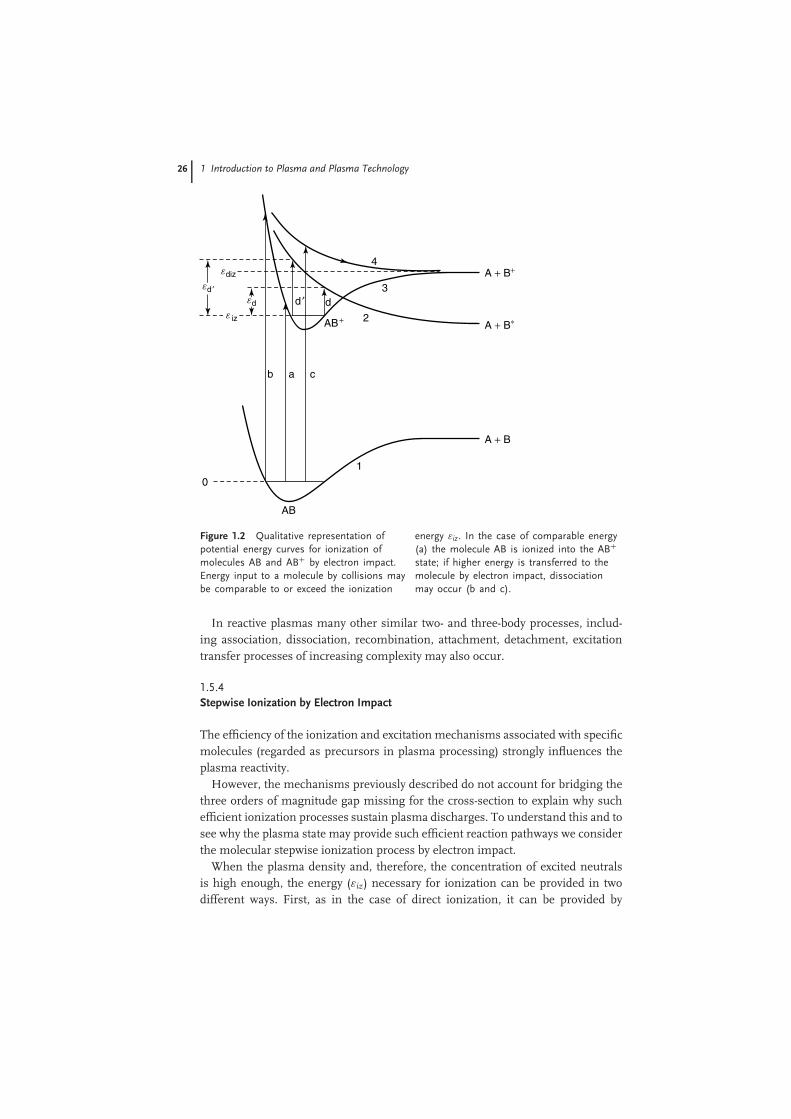
The first of the listed processes (Equation 1.35) takes place when the electronenergy does not greatly exceed the ionization potential. Some peculiarities ofmolecule ionization by electron impact can be seen from the illustrative potentialenergy curves for AB and AB+, shown in Figure 1.2, for collisions having a thresholdenergy εiz. For collisions having threshold energies higher than ionization, moleculedissociation occurs with excitation or further ionization of products (representedin states labeled as c and b, respectively in Figure 1.2).
The fastest internal motion of atoms inside molecules is their molecular vibration.But even molecular vibrations have a typical time period of 10−14 –10−13 s, whichis much longer than the interaction time between the plasma electrons and themolecules: a0/ ve ∼ 10−16 − 10−15 s (where a0 is the atomic unit of length and ve
is the mean electron velocity). This means that all kinds of electronic excitationprocesses under consideration, which are induced by electron impact, are muchfaster than the atomic motion inside the molecules. As a result, all the atomsinside a molecule can be considered to be frozen during the process of electronictransition, stimulated by electron impact. This fact is known as the Frank–Condonprinciple. The nondissociative ionization process (Equation 1.35) usually results inthe formation of a vibrationally excited ion (AB+)* and requires a little more energythan the corresponding atomic ionization. When the electron energy is relativelyhigh and substantially exceeds the ionization potential, dissociative ionization cantake place:
e + AB −→ A + B+ + e + e (1.36)
This ionization process (Equation 1.36) corresponds to electronic excitation intoa repulsive state of the ion, (AB+)*, followed by a decay of this molecular ion. Theenergy threshold for the dissociative ionization is essentially greater than that forthe nondissociative situation.
26 1 Introduction to Plasma and Plasma Technology
0
AB
1
2
3
4
dd ′
A + B
A + B+
A + B∗AB+
b a c
e iz
ediz
ed ′ed
Figure 1.2 Qualitative representation ofpotential energy curves for ionization ofmolecules AB and AB+ by electron impact.Energy input to a molecule by collisions maybe comparable to or exceed the ionization
energy εiz. In the case of comparable energy(a) the molecule AB is ionized into the AB+
state; if higher energy is transferred to themolecule by electron impact, dissociationmay occur (b and c).
In reactive plasmas many other similar two- and three-body processes, includ-ing association, dissociation, recombination, attachment, detachment, excitationtransfer processes of increasing complexity may also occur.
1.5.4Stepwise Ionization by Electron Impact
The efficiency of the ionization and excitation mechanisms associated with specificmolecules (regarded as precursors in plasma processing) strongly influences theplasma reactivity.
However, the mechanisms previously described do not account for bridging thethree orders of magnitude gap missing for the cross-section to explain why suchefficient ionization processes sustain plasma discharges. To understand this and tosee why the plasma state may provide such efficient reaction pathways we considerthe molecular stepwise ionization process by electron impact.
When the plasma density and, therefore, the concentration of excited neutralsis high enough, the energy (εiz) necessary for ionization can be provided in twodifferent ways. First, as in the case of direct ionization, it can be provided by
1.5 Reactive Plasmas 27
the energy of plasma electrons. Second, the high energy of preliminary electronicexcitation of the neutrals can be converted in the ionization process, which is calledstepwise ionization. If the level of electronic excitation is high enough, stepwiseionization is much faster and more efficient than direct ionization, because thestatistical weight of electronically excited neutrals is greater than that of freeplasma electrons. Hence, the probability that particle collisions are effective ishigher for excitation than for direct ionization. Furthermore, the probability thatthe subsequent electron collisions are effective for ionization is higher, becausethe energy difference between the excited state and the unbound electron state islower. We can consider the ionization process e + A → A+ + e + e, as the inverseto the three-body recombination event: A+ + e + e → A∗ + e → A + e, realizedthrough a set of excited states. For quasi-equilibrium or thermal plasmas we mayapply the principle of detailed equilibrium and consider the ionization processe + A → A+ + e + e as if going through the set of electronically inverse excitedstates of the three-body recombination process, in this interpretation the ionizationis regarded as a stepwise process.
For the ionization process we may define a rate coefficient kiz (Equation 1.37),derived by the summation of partial rate coefficients kiz,i, corresponding to the j-thelectronically excited state, over all states of excitation, taking also into accounttheir concentration:
kiz =n∑j
kiz,jNj(εj)
N0(1.37)
Further, we assume that the electron excited states in the target atoms, radicals,or molecules, are in quasi equilibrium with plasma electrons, and apply theBoltzmann statistics describing the electronically excited states as having a definedelectron temperature Te, and by taking into account the statistical weights (gj) ofthe states, their number density (Nj), Equation (1.38), and their energy (εn), becomelinked (note that the subscript ‘0’ refers to the ground state):
Nj =(
gj
g0
)N0 · e
(−
εjkbTe
)(1.38)
From statistical thermodynamics gj = 2 gizj2, where giz is the statistical weight ofan ion.
Assuming effective (inelastic) electron neutral excitation collision, the energytransfer from the impinging electron to an electron bound to the neutral targetparticle undergoing excitation is about Te. This means that excited particles with anenergy of about εj = εiz − Te make the major contribution to the sum of Equation(1.37). Taking into account that εj ∼ 1/j2, the number of states with an energy ofabout εj = εiz − Te and a ionization potential of about εiz = kBTe is of order j. Thus,from Equations (1.33) and 1.38 we can derive the reaction rates at each step:
kiz =(
giz
g0
)j3 · 〈σiz · v〉 · e
(− εiz
kbTe
)(1.39)

28 1 Introduction to Plasma and Plasma Technology
By substituting the thermal velocity and ionization cross-section as a result,
considering that from quantum mechanics j2 ≈ Z2e4 m(4πε0)2�2ε2
iz, the stepwise ionization
rate coefficient can be expressed as:
kiz ≈(
giz
g0
)1
(4πε0)5· me10
�3T3e
· e
(− εiz
kbTe
)(1.40)
Finally, comparing the stepwise- (Equation 1.40) and direct-ionization rate(kiz(Te)) coefficients we obtain:
kiz(Te)
kiz(Te)≈
(giza2
0
g0σ0
)·(
e4 m
(4πε0)2�2T2e
) 72
≈(
εiz
Te
) 72
(1.41)
From Equation (1.41) it is possible to argue that for σ0 ≈ a0 and for εiz/Te ≈ 10,as it is the case for a typical discharge, the stepwise ionization can be 103 –104 timesfaster than the direct one, as needed to sustain a plasma discharge.
1.6Plasma Sheaths
Confined plasmas which enter into contact with materials are of particular interestfor technical applications. A description of physical and chemical interactionsbetween plasma and material surfaces is provided in Chapter 3 for processingapplications. To understand the effective plasma regime at the plasma–substrateinterface, the features of plasma sheaths are introduced in the following.
Plasmas which are quasi neutral (ni≈ ne), develop positively charged boundarylayers called sheaths when approaching the material confining surfaces. This isdue to the higher thermal velocity of electrons, vth,e = (2 kBTe/me)1/2, exceedingthat of ions, vth,i = (2 kBTi/mi)1/2, by two orders of magnitude because of thedisproportioned mass ratio me/mi 1. Considering a simple (ideal) configurationof a plasma slab between two identical parallel grounded surfaces (walls), dueto charge neutrality, the electric field would be zero everywhere. However, sincein this configuration electrons are not confined by any electric field, due to theirhigher mobility they are rapidly lost to the walls, causing an abrupt change ofcharge concentration. Therefore at the plasma–wall interface charge neutrality isno longer satisfied and the electrical potential is found to be positive in the plasma(due to lack of negative charged particles) and rapidly decreasing within the plasmasheath space-domain, and approaching zero close to the walls within a few Debyelengths. The onset of this natural charge unbalance and consequent generation ofpotential barrier provides a self-confining mechanism for electrons that are thenpulled into the plasma by the electric field directed from the plasma to the walls.Under these conditions ions approaching the plasma sheath are accelerated to thewalls, causing ion bombardment. An important aspect of plasma sheaths is thattheir typical scale length is much smaller than the plasma spatial extension.
In fact, the sheath structure is more complex than just that of a boundarylayer. Indeed, to satisfy the continuity of ion flux through the sheath, a pre-sheath

1.6 Plasma Sheaths 29
between the plasma and the sheath has to be assumed. Furthermore, sheath featuresare strongly dependent both on boundary conditions (applied external voltages:continuous, oscillating high/low voltage) and on the plasma characteristics (i.e.,presence of electronegative ions, ion temperature, ionization degree).
For simplification, we consider a non-collisional plasma with Maxwellian electrontemperature Te, assuming cold ions such that (Te � Ti) and quasi neutrality. Underthese conditions at the plasma–sheath interface, considering a one-dimensionalspace dependence of quantities (1D-system) the momentum (ion-flux) and energyconservation along with the Maxwell Equation 1.9d read:
ni(x)u(x) = ni,s(x)us (1.42a)1
2miu
2(x) = 1
2miu
2s − eϕ(x) (1.42b)
∇2ϕ(x) = e
ε0(ne − ni) (1.42c)
where u is the ion speed and ni and ne the ion and electron densities in theplasma, respectively, nis and us are ion density and speed within the sheath, whereionization is assumed to be absent.
Given the electrons thermal equilibrium, the electron density is expressed bythe Boltzmann relation ne(x) = nes exp[−eϕ(x)/kBTe], with nes the electron densitywithin the sheath and kB the Boltzmann constant. By solving Equations 1.42a and1.42b with respect to u we find a relation for ni as a function of ϕ(x); which togetherwith the former Boltzmann equation for ne may be introduced into Equation 1.42cto give:
d2ϕ(x)dx2
= ens
ε0
exp[−eϕ(x)
/kBTe] −
[1 − eϕ(x)
εs
]− 12
(1.43)
where εs = 1/2miu2s and ns = nis=nes are the kinetic energy and density of
ions within the plasma sheath. Equation (1.43) is the basic nonlinear equationgoverning the sheath potential and the ion and electron densities; it allows fora first exact integral obtained by multiplying Equation (1.43) by dϕ/dx and thenintegrating with respect to x with the field free plasma boundary conditions atx = 0 : ϕ(0) = 0; [dϕ/dx]0 = 0; thus yielding:
1
2
[dϕ(x)
dx
]2
= ens
ε0
kBTe exp[−eϕ(x)/kBTe] − kBT + 2εs
[1 − eϕ(x)
εs
] 12 − 2εs
(1.44)
Equation 1.44 may be integrated numerically. However, analytical considerationsprovide some fundamental information on sheath features. The RHS of Equation(1.44) is positive-defined yielding to the consideration that the ion density within thesheath must always be larger than the electron density. Furthermore, by expandingup to the second order in ϕ(x) we get the relation eϕ(x)2/kBTe − eϕ(x)2/2εs ≥ 0,which may be satisfied for any value of x only if 2εs ≥ kBTi, leading to the Bohm
30 1 Introduction to Plasma and Plasma Technology
sheath criterion (Equation 1.45):
us ≥ uB ≡√
kBTe
mi(1.45)
From this condition the need is derived for an intermediate region betweenplasma (bulk) and plasma sheath in which ions are accelerated by electric an fieldto reach the speed us: this region is named presheath. Given the structural complexityof the plasma–wall interface matching (analytical and numerical) computationaltechniques are needed to provide solutions in specific configuration conditions andplasma regimes.
However, configurations in which a simple analytical solution is possible arestill representative in some plasma regimes and often applied in surface function-alization processes. This is the case of high negative voltage biasing of one of theelectrodes connected to the substrate to be plasma-treated or plasma-coated (see forinstance PVD processes dealt with in Chapters 2 and 9) imply driving high negativevoltages to one of the electrodes. In this case the sheath voltage is high and therelated energy is large compared with the electron thermal energy, eϕ(x)2 � kBTe,allowing Equation (1.44) to be simplified by neglecting the exponential term on theRHS. This is the case of the so called matrix sheath in which only ions are present inthe plasma sheath, with constant density ni(x) ≡ ni = ns. In this one-dimensionalconfiguration the Poisson equation deriving from the Gauss theorem (Equation1.9d) has a simple source term: d2ϕ(x)/dx2 = ens/ε0, which leads to the analyticalsolution: ϕ(x) = −(ens/2ε0)x2 from which for the boundary condition ϕ(s) = −V0,(where –V0 is the applied bias voltage) the sheath thickness s may be derived as afunction of the plasma characterizing parameters:
s = λDe ·√
2 eV0
kBTe(1.46)
Equation 1.46 confirms that the sheath scale length is much shorter than theplasma spatial extension. Considering the situation in which the kinetic energyof ions entering the sheath region is small compared with the plasma sheathpotential energy the momentum (ion flux), energy conservation and Gauss theorem(Equations 1.9b, c and d) simplify to:
eni(x)u(x) = J0
1
2miu
2(x) = −eϕ(x) (1.47)
d2ϕ(x)dx2
= − eni(x)ε0
where J0 represents the constant ion current. By simultaneous solution of thethree equations in Equation (1.47) it is possible to obtain a new differentialequation for the sheath potential, which further multiplied by its first derivativedϕ(x)/dx and finally integrated by setting the following boundary conditions:
References 31
dϕ(x)/dx ≡ 0 and ϕ(x) ≡ 0; leads to the solution:
ϕ(x) = − 3
√(3
2
)43
√mi
2e
(J0
ε0
)23√
(x)4 (1.48)
By imposing the following boundary conditions ϕ(s) ≡ −V0 in Equation (1.48),and solving for J0 we get the well-known Child’s law:
J0 = 4
9
ε0
s2
√2 eV3
0
mi(1.49)
In particular, Equation (1.49) provides a more refined relation between plasmasheath potential and sheath thickness than Equation (1.46):
s =√
3
2λDe 4
√(2 eV0
kBTe
)3
(1.50)
For collisional sheaths and other plasma sheaths regimes not falling into theconsidered simplified configurations, a dedicated analysis is necessary, as reportedin Ref. [18].
1.7Summary
In this chapter we have provided some fundamental and introductory concepts todevelop a more rigorous and comprehensive understanding of the plasma stateas well as providing basic tools to better appreciate the technical content of thisbook. Characterizing parameters and scaling quantities are provided in order tofacilitate the parameterization of different plasma states and to allow classificationof processing plasmas used for industrial applications.
Statistical and fluid description of plasmas are presented to betterunderstand the fundamentals of plasma reactivity and plasma–surface in-teractions as the characterizing features of technological plasmas for surfacefunctionalization.
References
1. Tonks, L. and Langmuir, I. (1929) Oscil-lations in ionised gases. Phys. Rev., 33,195.
2. Sweet, P.A. (1958) Electromagnetic phe-nomena, in Cosmical Physics, (ed. B.Lehnert), Cambridge University Press,London.
3. Priest, E.R. (1981) Solar Flare Magnetohy-drodynamics, Gordon and Breach SciencePublishers, UK.
4. Priest, E.R., Foley, C.R., Heyvaerst, J.,
Arber, T.D., Culhane, J.L. and Aton,
L.W. (1998) Nature of the heating Mech-
anism for the Diffuse Solar Corona.
Nature, 393, 545.
5. Petscheck, H.E. and Hess, W.N. (eds)
(1966) AAS-NASA Symposium of the
Physics of Solar Flares, NASA Spec.
Publ. SP-50, 1064, p.425.

32 1 Introduction to Plasma and Plasma Technology
6. Lui, A.T.Y. (1987) Magnetotail Physics,The John Hopkins University Press,Baltimore and London.
7. Heppner, J.P. Ness, N.F. Scearce, C.S.and SkillmanExplorer, T.L. (1963)10 Magnetic Field Measurements.J.Geophys.Res., 68, 1.
8. Gloeckler, G., Hamilton, D., Ipavich,F.M., Studemann, W., Wilken, B.,Kremser, G. and Hovestadt, D. (1985)Composition of the thermal and su-perthermal ions in the Near EarthPlasma Sheet, Proceedings on theChapman Conference on MagnetotailPhysics.
9. Bame, S.J., Aderson, R.C., Asbridge,J.R., Baker, D.N., Feldman,W.C., Gosling, J.T., Hones, E.W.,McComas Jr., D.J and Zwickl, R.D.(1983) Plasma regimes in the deep ge-omagnetic Field Tail: ISEE 3. Geophys.Res. Lett., 10, 912.
10. Bryant, D.A. (1993) Space plasmaphysics, in Plasma Physics, Chapter 9(ed. R. Dendy), Cambridge UniversityPress.
11. International Atomic Energy Agency,(1956) Volume 13: Legal, administrative,health and safety aspects of large-scaleuse of nuclear energy, Proceedings of theinternational conference on the peacefuluses of atomic energy; held in Geneva8 August – 20 August 1955, UnitedNations.
12. Butt et al. (1958) Proceedings of the2nd Conference on the Peaceful uses ofAtomic Energy, United Nations, Geneva,Vol. 32, p. 48.
13. Bellan, P.M. (2006) Fundamentals ofPlasma Physics, Cambridge UniversityPress.
14. Denes, F.S. and Manolache, S. (2004)Macromolecular plasma-chemistry: anemerging field of polymer science. Prog.Polym. Sci., 29, 815–885.
15. Shishoo, R. (2007) Plasma Technology inTextile Processing, Woodhead PublishingLtd. and CRC Press LCC.
16. Chiellini, E. (ed.) (2008) EnvironmentallyCompatible Food Packaging, CRC Pressand Woodhead Publishing Ltd.
17. Soloshenko, I.A. et al. (2000) Steriliza-tion of medical products in low-pressureglow discharges. Plasma Phys. Rep., 26(9), 792–800.
18. Lieberman, M.A. and Lichtemberg, A.J.(1994) Principles of Plasma Discharges andMaterial Processing, John Wiley & Sons,Inc., New York.
19. Krall, N.A. and Trivelpiece, A.W.(1986) Principles of Plasma Physics,San Francisco Press, Inc..
20. Schmidt, George, (1979) Physics of HighTemperature Plasmas, Academic Press.
21. Fridman, A. (2008) Plasma Chemistry,Cambridge University Press.
22. Stix, T.H. (1962) The Theory of PlasmaWaves, McGraw-Hill, New York.