part ii city of bend design standards
TRANSCRIPT

PART II
City of Bend Design Standards

i
Part II – Design Standards
Table of Contents
1.0 Use of These Design Standards ........................................................................... 2 1.1 Authority .......................................................................................................... 2
1.2 Deviations, Waivers, or Modifications ............................................................. 2
1.3 References to Other Standards ....................................................................... 3
1.4 Compliance with Americans with Disabilities Act ............................................ 3
1.5 Roadside Safety .............................................................................................. 3
1.6 Airport Design .................................................................................................. 4
2.0 Design Submittal Requirements ............................................................................ 3 2.1 Initial Plan Submittal ........................................................................................ 4
2.2 Survey Plat ...................................................................................................... 4
2.3 Information Required on Plans ........................................................................ 5
2.3.1 Streets – Plan and Profile Views ............................................................... 5 2.3.2 Sewer – Plan and Profile Views ................................................................ 7 2.3.3 Water – Plan and Profile Views ................................................................. 7 2.3.4 Stormwater – Plan and Profile Views ........................................................ 8 2.3.5 Landscaping and Irrigation Plans .............................................................. 8 2.3.6 Signing and Striping .................................................................................. 9 2.3.7 Grading and Erosion Control ..................................................................... 9 2.3.8 Calculations ............................................................................................. 10
2.4 CAD Drafting Standards ................................................................................ 10
2.4.1 National CAD Standards ......................................................................... 10 2.4.2 Drawing Creation and Layout .................................................................. 11 2.4.3 Electronic Drawing Format ...................................................................... 15 2.4.4 Drawing File Name .................................................................................. 15 2.4.5 Units ........................................................................................................ 16 2.4.6 Scale ....................................................................................................... 16 2.4.7 GIS Interface ........................................................................................... 17 2.4.8 Line Types, Weights, and Colors ............................................................ 17 2.4.9 Sheet Layout ........................................................................................... 18 2.4.10 Model Space and Paper Space ............................................................... 19

ii
2.4.11 Drawing Orientation ................................................................................. 19 2.4.12 Standard Details ...................................................................................... 19 2.4.13 Special Details ......................................................................................... 19 2.4.14 Terms and Abbreviations ........................................................................ 20 2.4.15 External Reference (Xref) ........................................................................ 20 2.4.16 Professional Stamps ............................................................................... 20 2.4.17 Plot Styles ............................................................................................... 20 2.4.18 Drawing Submittal ................................................................................... 20 2.4.19 City Standard Template ........................................................................... 21
2.5 Final Plan Submittal ...................................................................................... 21
2.6 As-Built Plan Submittal .................................................................................. 22
2.7 Notice to Proceed .......................................................................................... 22
2.8 Right of Way Permit Expiration ..................................................................... 23
3.0 Streets ................................................................................................................... 3 3.1 References ...................................................................................................... 3
3.2 Deviation from Streets Standards ................................................................... 3
3.3 Design Considerations .................................................................................... 4
3.3.1 Traffic Studies ........................................................................................... 4 3.3.2 Intersection Controls ................................................................................. 5 3.3.3 Design Speed ............................................................................................ 5 3.3.4 Sight Distance ........................................................................................... 6
3.4 Roadway Design Elements ............................................................................. 8
3.4.1 Right-of-way .............................................................................................. 8 3.4.2 Paved Roadway Widths and Lane Widths ................................................ 8 3.4.3 Roundabout Design ................................................................................. 12 3.4.4 Traffic Signal Design ............................................................................... 13 3.4.5 Medians ................................................................................................... 13 3.4.6 Islands ..................................................................................................... 14
3.5 Roadway Geometry ....................................................................................... 14
3.5.1 Intersections ............................................................................................ 14 3.5.2 Horizontal Alignment ............................................................................... 16 3.5.3 Vertical Alignment ................................................................................... 18
3.6 Other Right of Way Design Elements ............................................................ 20
3.6.1 Sidewalk .................................................................................................. 20 3.6.2 Curb Ramps and Crosswalks .................................................................. 21

iii
3.6.3 Transit Facilities ...................................................................................... 25 3.6.4 Driveways ................................................................................................ 27 3.6.5 Signing .................................................................................................... 28 3.6.6 Pavement Marking/Striping ..................................................................... 30 3.6.7 Curb Painting ........................................................................................... 31 3.6.8 Mailboxes ................................................................................................ 31 3.6.9 Illumination .............................................................................................. 32 3.6.10 Drainage .................................................................................................. 33 3.6.11 On-Street Parking .................................................................................... 33 3.6.12 Traffic Calming Devices .......................................................................... 33
3.7 Temporary Traffic Control ............................................................................. 33
3.8 Pavement Restoration Requirements ........................................................... 35
3.8.1 Grades ..................................................................................................... 35 3.8.2 Permits .................................................................................................... 36 3.8.3 Responsible Party ................................................................................... 37 3.8.4 General Requirements ............................................................................ 37 3.8.5 Pavement Sections ................................................................................. 37 3.8.6 Full, Modified, and T-Cut Patching Standards ......................................... 37 3.8.7 Traffic Control .......................................................................................... 38 3.8.8 Pavement Cut Restriction (Exception Process) ....................................... 39 3.8.9 Permits for Non Street Cut Restriction Streets and Street Cut Restriction
Streets with Approved Exception ............................................................ 40 3.8.10 Special requirements for Concrete Roads............................................... 40 3.8.11 New Development ................................................................................... 41 3.8.12 Temporary Pavement Restoration........................................................... 41 3.8.13 Testing and Warranty Requirements ....................................................... 41 3.8.14 No Dig/Trenchless Technology ............................................................... 42
4.0 Sanitary Sewer Systems ....................................................................................... 3 4.1 Sewer Main ..................................................................................................... 4
4.1.1 Depth ......................................................................................................... 5 4.1.2 Minimum Diameter .................................................................................... 5 4.1.3 Flow Calculation ........................................................................................ 5 4.1.4 Peak Factor (Domestic Flows Only) .......................................................... 7 4.1.5 Line Diameter and Velocity ....................................................................... 7 4.1.6 Minimum Grade (Gravity) .......................................................................... 7 4.1.7 Inverted Siphons ....................................................................................... 8

iv
4.1.8 Flows in Pressure Sewers ......................................................................... 8 4.1.9 Minimum Velocity ...................................................................................... 8 4.1.10 Maximum Velocity ..................................................................................... 8 4.1.11 Pressure Sewer Appurtenances ................................................................ 8 4.1.12 Waterline Crossings .................................................................................. 8 4.1.13 Marking Tape and Locate Wire ................................................................. 9 4.1.14 Materials .................................................................................................... 9 4.1.15 Construction ............................................................................................ 10 4.1.16 Septic System and Municipal Sewer Extensions..................................... 10 4.1.17 Sewer System Extension Requirements ................................................. 10
4.2 Manholes (Gravity) ........................................................................................ 11
4.2.1 Manhole Placement ................................................................................. 12 4.2.2 Manholes (Pressure to Gravity Sewer) .................................................... 12 4.2.3 Pressure Sewer Manholes ...................................................................... 12
4.3 Sewer Services ............................................................................................. 12
4.3.1 Cleanouts ................................................................................................ 13 4.3.2 Sample Manhole ..................................................................................... 13 4.3.3 Sample Manholes on Pressure Sewer Systems ..................................... 14
4.4 Sewage Pump Station Design ....................................................................... 14
4.4.1 Wetwells .................................................................................................. 15 4.4.2 Pumps ..................................................................................................... 17 4.4.3 Reliability and Redundancy ..................................................................... 18 4.4.4 Telemetry and SCADA ............................................................................ 18 4.4.5 Pump Control Panels .............................................................................. 19 4.4.6 Electrical Enclosure ................................................................................. 19 4.4.7 Hydrogen Sulfide Protection .................................................................... 21 4.4.8 Station Access ......................................................................................... 21 4.4.9 Station Fencing ....................................................................................... 21 4.4.10 Force Main Cleanout ............................................................................... 22 4.4.11 Flow Metering .......................................................................................... 22 4.4.12 Bypass System ........................................................................................ 22 4.4.13 Safety Systems ....................................................................................... 22 4.4.14 Lift Station Standards .............................................................................. 22
5.0 Water ..................................................................................................................... 2 5.1 Main Line ......................................................................................................... 2

v
5.1.1 Minimum Size ............................................................................................ 2 5.1.2 Marking Tape ............................................................................................ 2 5.1.3 Materials .................................................................................................... 3 5.1.4 Location ..................................................................................................... 3 5.1.5 Velocities ................................................................................................... 3 5.1.6 Pressures and Flow Calculations .............................................................. 4 5.1.7 Bends and Joint Deflection ........................................................................ 4 5.1.8 Thrust and Restrained Joints..................................................................... 5 5.1.9 Pressure Reducing Vaults ......................................................................... 5
5.2 Service Lines ................................................................................................... 5
5.2.1 Services Off of Fire Lines .......................................................................... 6 5.3 Valves .............................................................................................................. 7
5.3.1 Valve Location ........................................................................................... 7 5.3.2 Valve Types ............................................................................................... 7 5.3.3 Pressure Reducing Valves ........................................................................ 7 5.3.4 Blow-Offs ................................................................................................... 7
5.4 All-Weather Access ......................................................................................... 8
5.5 Meters ............................................................................................................. 8
5.5.1 Automatic Meter Reading Systems ........................................................... 8 5.5.2 Standard Meters ........................................................................................ 9 5.5.3 Vaults and Meter Boxes, Including Insulation ............................................ 9
5.6 Fire Services, Flows and Hydrants .................................................................. 9
5.6.1 Fire Flow Requirements .......................................................................... 10 5.6.2 Fire Service Lines .................................................................................... 11 5.6.3 Hydrants General .................................................................................... 11 5.6.4 Location ................................................................................................... 11 5.6.5 Concrete Pad .......................................................................................... 12
6.0 Stormwater ............................................................................................................ 2 6.1 Design Storm ................................................................................................... 2
6.1.1 Water Quality Design Storm ...................................................................... 2 6.1.2 Water Quality Design Volume ................................................................... 2 6.1.3 Water Quality Design Flow ........................................................................ 2 6.1.4 Flow Control and Conveyance .................................................................. 3
6.2 Hydrologic Basis of Design ............................................................................. 3
6.2.1 Hydrologic Design Criteria ......................................................................... 3
vi
6.2.2 Drainage facility testing ............................................................................. 4 6.3 Water Quality Treatment ................................................................................. 8
6.3.1 Treatment Controls .................................................................................... 8 6.4 Conveyance .................................................................................................. 10
6.4.1 Pipe Material ........................................................................................... 11 6.4.2 Pipe Diameter and Length ....................................................................... 11 6.4.3 Placement and Alignment ....................................................................... 11 6.4.4 Outfalls .................................................................................................... 11 6.4.5 Storm Drain Debris and Safety ................................................................ 11
6.5 Flow Control .................................................................................................. 11
6.5.1 Sequential Implementation ...................................................................... 12 6.5.2 Fencing .................................................................................................... 12 6.5.3 Embankments ......................................................................................... 12 6.5.4 Access ..................................................................................................... 13
6.6 Drainage Submittals ...................................................................................... 13
6.6.1 Concept Drainage Report ........................................................................ 14 6.6.2 Concept Drainage Report Applicability .................................................... 14 6.6.3 Road and Drainage Plans ....................................................................... 14 6.6.4 Minimum Plan Elements .......................................................................... 15
7.0 Grading and Erosion Control ................................................................................. 2 7.1 Erosion Control ................................................................................................ 2
7.1.1 Erosion Control Plans ................................................................................ 2 7.1.2 Erosion Control Maintenance .................................................................... 3 7.1.3 Erosion Control Slope Mitigation ............................................................... 4
8.0 Franchise Utilities .................................................................................................. 2 8.1 Franchise Utilities in Public Rights-of-way ...................................................... 2
8.1.1 General ...................................................................................................... 2 8.2 New Construction and Conduit Banks ............................................................. 2
8.3 Shared Trenches ............................................................................................. 2
8.4 Trenching and Patching in Paved Right-of-way Areas .................................... 3
8.5 Small Wireless Facilities .................................................................................. 3
8.5.1 Deviation from Small Wireless Facility Standards ..................................... 3 8.5.2 Co-Location ............................................................................................... 4

vii
8.5.3 Location Guidelines ................................................................................... 4 8.5.4 Franchise Fees, License Fees and Permit Fees ....................................... 5
9.1 Canal and Irrigation Laterals.................................................................................. 1 9.2 Design ............................................................................................................. 1
9.3 Materials .......................................................................................................... 1
9.4 Testing ............................................................................................................. 1
9.5 Easements ...................................................................................................... 1
10.0 Surveying .............................................................................................................. 2 10.1 Datum Requirements ...................................................................................... 2
10.1.1 Horizontal Datum ....................................................................................... 2 10.1.2 Vertical Datum ........................................................................................... 2
10.2 Aerial Photography and Photogrammetry ....................................................... 2
10.2.1 Photo Targets ............................................................................................ 2 10.2.2 Supplemental Ground Surveying............................................................... 2 10.2.3 Confidence Points ..................................................................................... 2
10.3 Requirements for a Licensed Surveyor ........................................................... 3
10.4 Use of Benchmarks ......................................................................................... 3
10.5 Survey Data Required on Plans ...................................................................... 3
10.6 Construction Phase Surveying ........................................................................ 4
10.6.1 Supplemental Control ................................................................................ 4 10.6.2 Construction Staking ................................................................................. 4 10.6.3 Cutsheets .................................................................................................. 5
10.7 Final Submittal of Electronic Files ................................................................... 5
10.7.1 CAD Files .................................................................................................. 5 10.7.2 Word Processing Documents .................................................................... 5 10.7.3 Image Files ................................................................................................ 5
11.0 Geotechnical Engineering ..................................................................................... 2 11.1 Geotechnical Data Report ............................................................................... 2
11.2 Geotechnical Recommendations Report ......................................................... 3
11.3 Pipelines, Appurtenances, and Ancillary Structures ........................................ 3
11.3.1 Excavation ................................................................................................. 3 11.3.2 Thrust Restraint ......................................................................................... 3

viii
11.3.3 Drywells ..................................................................................................... 4 11.3.4 Seismic Design .......................................................................................... 4 11.3.5 Ancillary Structures ................................................................................... 4
11.4 Pavement Design ............................................................................................ 4
11.4.1 Traffic Analysis .......................................................................................... 4 11.4.2 Subgrade Properties ................................................................................. 5 11.4.3 Inputs for 1993 AASHTO Pavement Design Procedure ............................ 5 11.4.4 Minimum Design Life, and Life-cycle Cost Analysis .................................. 6 11.4.5 Minimum AC Thickness ............................................................................. 6 11.4.6 Minimum PCC Thickness and Joint Design .............................................. 6
11.5 Sign, Luminaire, and Signal Pole Foundations in the Public Right of Way ..... 6
11.6 Other Transportation Design Elements ........................................................... 6
11.7 Blasting ............................................................................................................ 7
11.8 References ...................................................................................................... 7
11.8.1 Utility Systems; Pipelines, Appurtenances, and Ancillary Structures ........ 7 11.8.2 Transportation Structural Elements; Pavements, Bridges, Culverts, Embankments, Retaining Walls, and Cut Slopes .................................................. 7
12.0 Landscape Architecture and Irrigation Systems .................................................... 1 12.1 Applicability ..................................................................................................... 1
12.2 Landscape Plan Submittals ............................................................................. 1
12.2.1 Design Parameters .................................................................................... 2 12.2.2 Landscape Conservation ........................................................................... 2 12.2.3 Street Trees and Plants ............................................................................. 4 12.2.4 Standard Materials and Equipment ........................................................... 6
12.3 Irrigation Plan Submittals ................................................................................ 7
12.3.1 Design Parameters .................................................................................... 7 12.3.2 Drip Irrigation Design ................................................................................. 8 12.3.3 Standard Materials and Equipment ........................................................... 8
13.0 Electrical Systems ................................................................................................. 3 13.1 Applicable Codes, Standards, and Regulations .............................................. 3
13.2 Hazardous and Corrosive Areas ..................................................................... 4
13.3 Design Approach and Guidelines .................................................................... 4
13.3.1 Distribution System ................................................................................... 4

ix
13.3.2 Standby Power .......................................................................................... 5 13.3.3 Fire Alarm .................................................................................................. 5 13.3.4 Security System and Facility Access Control ............................................ 5
13.4 Design Presentation ........................................................................................ 5
13.4.1 Legend ...................................................................................................... 5 13.4.2 Site Plan .................................................................................................... 5 13.4.3 Process and Facility .................................................................................. 6 13.4.4 Single-Line Diagrams ................................................................................ 6 13.4.5 Motor Control Schematic Diagrams........................................................... 6
13.5 Schedules ........................................................................................................ 7
13.5.1 Details ....................................................................................................... 8 13.5.2 Specifications ............................................................................................ 8
13.6 Design Criteria ................................................................................................. 8
13.6.1 Listed and Labeled Equipment .................................................................. 8 13.6.2 Calculations ............................................................................................... 8 13.6.3 Distribution Voltage ................................................................................... 8 13.6.4 Utilization Voltage ...................................................................................... 9 13.6.5 Voltage Drop ............................................................................................. 9 13.6.6 Demand Factors ........................................................................................ 9 13.6.7 Metering .................................................................................................... 9 13.6.8 Branch Circuits .......................................................................................... 9 13.6.9 Panelboards ............................................................................................ 10 13.6.10 Motor Control ......................................................................................... 10 13.6.11 Equipment Identification ......................................................................... 11 13.6.12 Raceways ............................................................................................... 11 13.6.13 Wire and Cable ...................................................................................... 12 13.6.14 Color Coding .......................................................................................... 12 13.6.15 Circuit Identification ................................................................................ 13 13.6.16 Enclosures ............................................................................................. 13 13.6.17 Fiber-optic Cable .................................................................................... 13 13.6.18 Grounding .............................................................................................. 13 13.6.19 Lighting ................................................................................................... 13 13.6.20 Street Lighting ........................................................................................ 14
14.0 Instrumentation and Control Systems ................................................................... 2 14.1 Scope .............................................................................................................. 2

x
14.2 Design Deliverables ........................................................................................ 2
14.2.1 Legend ...................................................................................................... 2 14.2.2 Process and Instrumentation Diagrams .................................................... 2 14.2.3 Process Control Functional Narratives ...................................................... 3 14.2.4 PLC I/O List ............................................................................................... 4 14.2.5 Control System Block Diagram.................................................................. 4 14.2.6 Sample Loop Drawings ............................................................................. 5 14.2.7 Instrument List ........................................................................................... 5
14.3 Design Criteria ................................................................................................. 5
14.3.1 Enclosures ................................................................................................. 5 14.3.2 PLC I/O Special Requirements.................................................................. 6 14.3.3 Typical PLC I/O at Remote Station Facilities ............................................. 6 14.3.4 Tag Numbering .......................................................................................... 7 14.3.5 Network Communication ........................................................................... 7 14.3.6 Radio Pathway Study ................................................................................ 8 14.3.7 Instruments and Components ................................................................... 8 14.3.8 Testing Requirements ............................................................................... 8

SECTION 2-1
General Information
Table of Contents 1.0 Use of These Design Standards ................................................................................... 2
1.1 Authority ...................................................................................................................... 2
1.2 Deviations, Waivers, or Modifications ..................................................................... 2
1.3 References to Other Standards ............................................................................... 3
1.4 Compliance with Americans with Disabilities Act .................................................. 3
1.5 Roadside Safety ......................................................................................................... 3
1.6 Airport Design ............................................................................................................. 4
PART II | SECTION 2-1 | PAGE 2 OF 4 MARCH 2019
1.0 Use of These Design Standards
These Design Standards provide required design constraints, methodologies, features, and practices that shall be implemented in all designs of Public Works facilities in the City of Bend. If, in practice, a designer encounters a design feature for which a Design Standard does not exist, the responsible designer shall use best professional judgment for completing the design. The City Engineer retains the right to establish requirements for design of public works features for which a Design Standard does not exist and the designer shall modify designs to reflect all requirements of the City Engineer. To avoid re-work, the responsible designer should seek approval from the City Engineer, early in the design process when it becomes apparent to the responsible designer that a project requires design of features for which a Design Standard does not exist.
These Design Standards provide some guidance regarding permitting that may be required for some projects, but this document is not intended to identify the permitting requirements. The City of Bend Community Development Department and other agencies should be consulted for permits that will be required for projects. Prior to design, the designer should consider proximity to all private utilities, canals, or railways that may exist and understand their permitting and approval requirements. Their requirements are likely different than these design standards but could impact overall design and layout of public infrastructure.
These design standards are intended to complement the City of Bend’s standard construction specifications, which are based on the Oregon Standard Specifications for construction as supplemented and/or modified by the City of Bend Special Provisions.
1.1 Authority These Public Works Design Standards have been adopted by the City Council and minor amendments may be made by the City Engineer. Bend Development Code Chapter 3 also contains applicable land use design standards.
Throughout these design standards references are made to City Engineer approval. The City Engineer has the authority to delegate this approval, with the exception being to deviations, waivers, or modifications. Users are encouraged to work through the permit center at CDD to seek the lowest level of approval needed to prevent bottlenecks and time delays. City staff at the permit center will seek additional approval or input as needed. Users are discouraged from contacting various divisions, and division staff for additional information. Doing so will likely slow approval and provide misinformation.
1.2 Deviations, Waivers, or Modifications Any deviations, waivers, or modifications from the City design standards must comply with the process identified in Part I, Section 2 Change Process. The City Engineer will make a final determination on the request.

PART II | SECTION 2-1 | PAGE 3 OF 4 MARCH 2019
1.3 References to Other Standards The City of Bend intends to align its public works design and construction practices with public works industry standards. The Bend Design Standards and Construction Specifications refer to the latest version of various third party standards that contain design or construction elements required for compliance with the Bend Design Standards and Construction Specifications. Where third party standards are referenced, the responsible designer shall obtain copies of these public domain and/or copyrighted standards as required to understand and prepare designs in compliance with these standards. In no case shall the City of Bend be responsible for providing access to, or copies of, any referenced standard to a Consultant, Contractor, Developer, legal counsel or other party unless this standard is a unique standard published by the City of Bend.
1.4 Compliance with Americans with Disabilities Act
Design engineers are responsible for implementing appropriate sections of the latest versions of the “Americans with Disabilities Act Accessibility Guidelines (ADAAG)” for private property and buildings and the “Public Rights-of-Way Accessibility Guidelines (PROWAG)" for public rights-of-ways and private rights-of-ways with public access easements. Both documents are published by the United States Access Board to ensure access compliance for people with disabilities to buildings, properties and roadway facilities. The engineer should recognize that field conditions vary greatly and must be thoroughly investigated to ensure applicable criteria are met or exceeded. In addition, the City of Bend has specific design standards that supplement and work as a companion to the ADAAG and PROWAG requirements. The design engineer must also ensure these City standards are met.
Every attempt has been made to provide files in accessible formats. If you need to request an alternative version of a file posted on this site, please contact us (hyperlink) and provide as much information as you can about the document, its location, and your specific needs.
1.5 Roadside Safety Roadside is defined as the area between the edge of the traveled way and the right-of-way. Roadside crashes account for 30 percent of the total fatal crashes nationally. The roadside environment plays a significant role in the injury or fatality outcome of leave the road events.
There are numerous reasons that can cause a driver to leave the road, from crash avoidance, to driver distraction. Regardless of the reason for a vehicle leaving the roadway, a roadside environment free of fixed objects with stable, flattened slopes reduces crash severity. These standards and specifications strive to reduce the likelihood of vehicles leaving the pavement; to create designs that do not include obstacles; and to reduce the impact severity by using an appropriate breakaway device. Within this document, the term 'obstacles' covers a variety of right-of-way design elements. The engineer is responsible for designing facilities; structures, signage, and landscape that ensure applicable criteria are met or exceeded.

PART II | SECTION 2-1 | PAGE 4 OF 4 MARCH 2019
1.6 Airport Design The City of Bend owns, operates, and maintains the City of Bend Airport. This facility is designed to the Federal Aviation Administration’s (FAA) requirements. Nothing in these design standards is intended to supersede or replace the FAA requirements. Where the FAA is silent, or has no design requirements, the City of Bend Design Standards shall be used.

PART II | SECTION 2-2 | PAGE 1 OF 23
MARCH 2019
SECTION 2-2
Design Submittal Requirements
Table of Contents 2.0 Design Submittal Requirements ................................................................................ 3
2.1 Initial Plan Submittal .............................................................................................. 4 2.2 Survey Plat ............................................................................................................ 4 2.3 Information Required on Plans .............................................................................. 5
2.3.1 Streets – Plan and Profile Views ................................................................. 5 2.3.2 Sewer – Plan and Profile Views .................................................................. 7 2.3.3 Water – Plan and Profile Views ................................................................... 7 2.3.4 Stormwater – Plan and Profile Views .......................................................... 8 2.3.5 Landscaping and Irrigation Plans ................................................................ 8 2.3.6 Signing and Striping .................................................................................... 9 2.3.7 Grading and Erosion Control ....................................................................... 9 2.3.8 Calculations ............................................................................................... 10
2.4 CAD Drafting Standards ...................................................................................... 10 2.4.1 National CAD Standards ........................................................................... 10 2.4.2 Drawing Creation and Layout .................................................................... 11 2.4.3 Electronic Drawing Format ........................................................................ 15 2.4.4 Drawing File Name .................................................................................... 15 2.4.5 Units .......................................................................................................... 16 2.4.6 Scale .......................................................................................................... 16 2.4.7 GIS Interface ............................................................................................. 17 2.4.8 Line Types, Weights, and Colors ............................................................... 17 2.4.9 Sheet Layout ............................................................................................. 17 2.4.10 Model Space and Paper Space ................................................................. 19 2.4.11 Drawing Orientation ................................................................................... 19 2.4.12 Standard Details ........................................................................................ 19 2.4.13 Special Details ........................................................................................... 19 2.4.14 Terms and Abbreviations ........................................................................... 20 2.4.15 External Reference (Xref) .......................................................................... 20 2.4.16 Professional Stamps .................................................................................. 20 2.4.17 Plot Styles .................................................................................................. 20 2.4.18 Drawing Submittal ..................................................................................... 20 2.4.19 City Standard Template ............................................................................. 21

PART II | SECTION 2-2 | PAGE 2 OF 23
MARCH 2019
2.5 Final Plan Submittal ............................................................................................ 21 2.6 As-Built Plan Submittal ........................................................................................ 21 2.7 Notice to Proceed ................................................................................................ 22 2.8 Right of Way Permit Expiration ........................................................................... 23

PART II | SECTION 2-2 | PAGE 3 OF 23
MARCH 2019
2.0 Design Submittal Requirements The purpose of this section is to clearly identify the requirements for design submittal of proposed plans for approval by the City. In Part I, Section 3 is a table that is provided to help explain all the phases of land development. This table is not intended to identify every aspect, but rather to give the designer an idea of what will be required to submit to the City for approval for each phase of the development. It also identifies what the City is required to do for each of those phases of submittal. For construction plans to be reviewed, this table identifies the required phases of approval needed prior to construction plan submittal. For construction plans to be reviewed the applicant must have all site plan and land use planning approval. It is highly recommended that the designer review the land use decision that is tied to the property they are designing for regarding public facilities. Often times the land use decision has specific requirements of sizing, placement, or other requirements that must be satisfied. The design of those requirements relies on this document. The designer is responsible for ensuring all required elements that are contained in a land use decision are shown on plan submittals. The requirements for site plan submittal are identified within the Bend Development Code. The Bend Code specifies what is required to be shown on any site plan submitted, which typically has significantly less detail than construction plans. The site plan review process is similar to construction plans, however the comments provided by the City are only to the level of detail that was provided on the plans and required by the City Development Code. Construction plans typically have far more detail and therefore City comments will also be more detailed during the construction plan review. Plans and specifications for construction of any City utility that includes water, sewer, stormwater, streets (including alleys) and any other city infrastructure must be submitted to the City Engineer, or designee, for approval prior to construction.
Applicants shall submit complete electronic sets of plans and technical specifications for review by the City Engineer, or designee. A complete set of plans will show all the required elements as identified in this section. All plans must meet the City of Bend CAD Drafting Standards, which are outlined later in this section. Submittals shall include a copy of the Administrative Review and Decision and be accompanied by a transmittal letter with all pertinent materials attached, including a copy of the approved site plan. All designs shall conform to the current City of Bend Standards and Specifications.
Any project work on the proposed site conducted prior to approval of plans by the City Engineer and/or prior to Notice to Proceed by the City of Bend is not allowed. All grading and clearing shall be subject to the provisions of the most recently adopted City of Bend Grading and Clearing Ordinance located in the Bend City Code Chapter 7. In addition, Part II, Section 2-7 of these design standards contains specific requirements to address grading and drainage. A complete plan for erosion control and grading must be submitted for approval. Only those grading activities approved on the tentative site plan or plat under the applicability standards of the ordinance are allowed to be conducted prior to the approval of the engineered plan set. An AutoCAD format template drawing for use by designers is available from the City of Bend Permit Counter. The drawing contains the City’s required layer naming convention, standard blocks and symbols, and other information related to drafting standards.

PART II | SECTION 2-2 | PAGE 4 OF 23
MARCH 2019
Designers are required to use the template for all City infrastructures. Additional information regarding the use of the template drawing is identified below within the CAD Drafting Standards.
2.1 Initial Plan Submittal Depending on the size and complexity of the project, the City Engineer or designee shall require that construction plans be submitted at different phases of design. This requirement will expedite review and approval overall and prevent major changes being required by the City late in the design process that can be both costly and timely. As an example of things that may require early design review could be but are not limited to: an entire development that has multiple streets with all related infrastructure, a street connecting to an arterial, pressure sewer system, large stormwater elements, connecting water mains of various sizes, multiple sewer laterals, or complex ADA access. The designer must check with the City Engineer or designee to determine if early design submittals will be required. All City capital improvement projects or projects that are identified as part of a master plan will require 30, 60, and 95 percent construction plan submittals prior to final sign off. At each review detailed comments will be provided and recorded by City staff using the City of Bend Project Managers Manual for design review. All comments will be provided to the designer and each comment must be addressed at submittal phase.
Construction documents for projects involving land use actions must be complete prior to submittal. Plans will be reviewed in a timely manner through an internal process that ensures a complete and consistent review by all affected departments. The plans shall be returned electronically with required modifications clearly noted and identified thereon. Comments will be consistent with the requirements specified in this document and City of Bend Development Code. All comments need to be satisfied and include written responses to all comments prior to final approval.
In addition to the plan submittal, any technical specifications that are appropriate for any portion of the project must also be submitted with the plans. These include pumps, motors, controllers, communication/telemetry systems, special valves, or other items that will ultimately need to be owned and operated by the City.
2.2 Survey Plat When a plat is necessary to create a land division either as a subdivision or partition, a preliminary plat showing complete information shall be submitted to the project Planner or designee for review and comments. The plat must be signed by all required parties and recorded with the Deschutes County Recorder prior to the City’s final acceptance of any public facilities. When the review comments have been addressed, and the County Surveyor has approved the plat, as indicated by signature on the mylar, the plat shall be submitted through the Permit Center to the project Planner, or designee, for signature. The required public facilities must be complete and accepted by the City and infrastructure as-builts submitted (section 2.6) prior to receiving signatures from the Planning Manager or the City Engineer.
PART II | SECTION 2-2 | PAGE 5 OF 23
MARCH 2019
2.3 Information Required on Plans In addition to specific information required in Part 2 Section 2.4 below, the following shall also be included on all plans:
• Identify the location of all public and private utilities, both existing and proposed
• Street names including area quadrant (i.e. N.E., N.W., S.E., or S.W.)
• Special details for items not shown on Standard Drawings
• All relevant public facility data, including size and quantity of improvements
• Fire flow requirements as per City of Bend Fire Marshal
• Show existing and proposed ROW, property lines, survey monuments and label assessor’s parcel numbers
• Refer to Part II, Section 2-10 (10.5 ) for Survey Data Required on Plans
• Any existing or proposed easements
2.3.1 Streets – Plan and Profile Views • Vertical and horizontal curve data
• Roadway centerline and stationing along centerline to a minimum of 300 feet beyond proposed project limits.
• Slopes of centerline, sidewalks, and gutter lines, and running slope of roadway
• Continuous stopping sight distance along roadway
• Intersection sight distance and decision sight distance at intersections
• Radii and grades at the ends, midpoint, and 1/4 points of curb returns
• Typical cross-section location of streetlights at intersections
• Sight distance measurements and protections
• Pedestrian treatments including adequate information for ADA compliance checks including a detailed grading plan
• Spot elevations sufficient to demonstrate accessible ramps at all sidewalk intersections
• Counter slope of roadway at ramp
• Slope, utility and other existing and proposed easements
• Clear vision area at intersections
• Grade of all sidewalks shall be shown on the profile Conceptual locations of driveway approaches
2.3.1.1 Streets - Roundabouts In addition to specific information required in Section 2.3.1 above, the following shall also be included on all plans when applicable.
• Roundabout inscribed circular diameter labeled

PART II | SECTION 2-2 | PAGE 6 OF 23
MARCH 2019
• Approach and Exit alignment and design shown for each leg (include stationing and profiles)
• Centerline stationing and profiles for circulatory roadway
• Speed checks (in design report is ok)
• Design vehicle identified (in design report is ok)
• Turning movement analysis for design vehicle (in design report is ok)
• Vehicle path alignments and path overlap checks (in design report is ok)
• Bicycle treatments including ramp details
• Splitter island details and curb types, elevations
• Approach and circulatory roadway widths
• Truck apron design details including reveal curb and interior curb details
• Cross-slopes labeled and identified for all roadways including truck apron
• Illumination including pole type and location, wattage, fixture type, horizontal and vertical luminance and uniformity
• Pavement markings and striping
• Signing
• Sight distance measurements and protections
• Grading, drainage, landscaping
2.3.1.2 Streets - Traffic Signals In addition to specific information required in section 2.3.1 above, the following shall also be included on all plans when applicable.
• Provide traffic signal removal plan
• Show location, direction, size and type of MUTCD number of all permanent street signing
• Show location, wiring, and mast arm for intersection street lighting
• Provide traffic and pedestrian signal design showing relationships between signal head placement and lane striping, lines of sight, and pedestrian movements
• Show signal poles, pedestrian poles, and controller cabinet foundation locations with relationship to sidewalks and rights-of-way.
• Provide conduit design and location
• Include wiring diagram
• Include phasing and timing diagram
• Include detection plan. For loop detectors, show wiring diagram and layout plan. For video detection, include camera placement and detector zone setup and logic.

PART II | SECTION 2-2 | PAGE 7 OF 23
MARCH 2019
2.3.2 Sewer – Plan and Profile Views • Location of existing and proposed manholes, sewer line, and services in plan and
profile
• Stationing along sewer line
• Invert and rim elevations at existing and proposed manholes
• On all manholes with multiple inverts into/out of manholes, clearly identify with directional designation (N,S,E,W, etc.) and notation of direction of flow (in or out)
• Sewer extended to provide service to adjacent properties
• A profile showing sufficient cover and finished street grade and crossing locations showing potential conflicts
• All conflicting public and private utilities indicated up to 300 feet outside of the proposed development.
• Sewer service provided to each lot with station and offset at end of service line
• Pipe material identified
• Slopes, distances, and diameter of main runs
• Slope and invert elevation shown on proposed sewer lines stub-outs for future extension
• Where a line is to be connected to an existing system, the following NOTE should be placed on the final plans: “Contractor shall verify the location of the existing sanitary sewer line before proceeding with trenching.”
• Water and sewer information should be on the same plan sheet unless otherwise approved by the City Engineer.
Where applicable, a NOTE stating, “Sewer taps to be performed by City-approved Contractor.”
2.3.3 Water – Plan and Profile Views • Location of valves, fittings, fire hydrants and services
• Stationing along waterline
• A profile showing sufficient minimum cover and finished street grade and crossing locations showing potential conflicts
• Fire flow requirements
• Utilities conflicts
• Service to each lot with station and offset at end of service line
• Pipe curvature radius and/or joint deflection angle
• Fittings specified with stations
• All fire service lines plan and profile

PART II | SECTION 2-2 | PAGE 8 OF 23
MARCH 2019
• Thrust block details
• Restrained joint pipe table showing restrained joint lengths for all restrained pipe
• Water and sewer information should be on the same plan sheet unless otherwise approved by the City Engineer.
2.3.4 Stormwater – Plan and Profile Views • Location of manholes, storm lines, catch basins, treatment controls, and other
appurtenances
• Stationing along main storm line
• Invert elevations shown at manholes, catch basins, and inlets
• Profile of storm pipe showing cover and finished street grade and crossing locations showing potential conflicts
• All utilities and services with conflicts indicated on profiles
• Pipe material identified
• Slopes, distances and diameter of main runs
• Permanent drainage plan, including drainage basin boundaries and areas
• Existing or natural drainage courses, canals, rivers and ponds
• Curb inlet basins on all arterial and collector streets
• Drainage control at low spots and storm sewers at sag curves
• Slope easements
• Wooden utility pole location
• Storm water information should be on the same plan sheet as street improvements unless otherwise approved by the City Engineer.
2.3.5 Landscaping and Irrigation Plans For all City owned public facilities and City owned landscaping, the following items shall be required on all plan submittals.
• Existing tree plan showing all existing trees 6-inch-diameter at breast height (DBH) and larger. Show all existing trees proposed for removal or relocation
• Specify any existing vegetation areas that will remain as-is • Proposed protection fencing locations and type of protective measures • Location of all structures, streets, driveways, walkways and other hard surfaces • Identify all proposed plant materials with common name, botanical nomenclature,
plant installation size and quantity of each species • Existing and proposed grading and drainage systems • Specify mulch types, applied depth, and location • Specify location of all turf areas and types of proposed turf • Specify hydrozones and landscaping features

PART II | SECTION 2-2 | PAGE 9 OF 23
MARCH 2019
• Schematic piping layout and size to water source
• Location of sleeves under all hard surfaces or construction obstructions
• Location, type, and coverage of each irrigation zone
• Table of hydraulic calculations showing all zones and their overall usage Site structures and obstacles that interfere with the coverage and performance of the irrigation system
• Schedule of heads, numbers of circuits, and sizes of piping
• Location of irrigation controller by note (if remote-offsite) or symbol • Location of backflow device and ‘blowout’ for winterization • Location of all points of connection (POC)
2.3.6 Signing and Striping • Onsite and offsite signing including MUTCD sign type or legend, size of sign, type
of post.
• Existing signing, including MUTCD sign type or legend, to a minimum 300 feet beyond the proposed project limits including size of sign, and condition.
• Proposed signing with MUTCD sign types or legends
• Show any required Type III barricades or road end signage on the plan sheets
• Stations or distances to proposed signing
• Existing signing to be replaced
• Schematics or legends of nonstandard signs
• Existing striping, transitions, and tapers, including lane widths,
• Proposed striping with match points identified
• Proposed lane width and turn bay storage lengths dimensioned
• Line and symbol types and colors identified
• Beginning and end points of tapers, per AASHTO and City of Bend standards, identified with stations
• Removal of existing striping identified
• Striping Quantity Table, including total linear feet of 4-inch line, 8-inch line, 12-inch thermoplastic, and number of symbols by type
2.3.7 Grading and Erosion Control The following items shall bell be shown on all plans, as applicable.
• Construction entrance(s) / Wheel washes
• Storm Inlet protection
• Tree protection / removal
• 1 foot contours for existing and proposed grades

PART II | SECTION 2-2 | PAGE 10 OF 23
MARCH 2019
• Slope mitigation (during construction and post construction)
• Concrete washout
• Stock pile areas
• Stream / Waterway protection
• Sediment control
2.3.8 Calculations The following calculations shall be shown on all plans:
• Drywell capacity/testing volume in gallons per hour or gallons per 1/2 hour
• Storm runoff hydrograph and drainage system sizing
• Calculations for both offsite drainage and existing site drainage
• Pump station and wetwell sizing, including pump station operating parameters
2.4 CAD Drafting Standards These drafting standards have been established to facilitate producing drawings that are consistent in appearance and present sufficient information to allow the construction contractor, inspection staff, and City reviewers to know both the broad scope and the details necessary to complete a successful project. Adherence to these standards will:
• Aid in the efficient review and response to of construction plan submittals • Aid the City in maintaining a complete facilities record of its assets • Provide an accurate post-construction record of the work
These drafting standards are to be followed by all designers, public and private, who are preparing drawings for the City of Bend. If a project extends, replaces, or calls for construction of infrastructure or utilities that will become the responsibility of the City, these drafting standards will apply. This applies to all infrastructure projects regardless of the initial funding source.
Questions regarding use of these guidelines should be directed to the City of Bend Utility Division CAD/GIS Group.
2.4.1 National CAD Standards The National CAD Standards (NCS) were used as the basis for development of the Bend CAD standards. As much as possible of the NCS guidance was used in developing the Bend drafting standards. Use of the NCS modules varies depending on the content and applicability. Much of the NCS guidance is directed at building design and construction and only a small portion is focused on utilities and civil design.
Although the City of Bend templates, standard details, and drafting standards are broadly applicable to utility projects, the information and guidance provided herein is not all-encompassing. When a designer finds a need to add or create a feature not contained or addressed in these standards, their first resource should be the NCS guidance.

PART II | SECTION 2-2 | PAGE 11 OF 23
MARCH 2019
2.4.2 Drawing Creation and Layout The City of Bend has created and provides a standard template drawing to designers. This template is populated with the layers to be used.
Drawings will be available to the public, therefore individual company or engineering firm copyrights will not be permitted to be included on plans.
2.4.2.1 Layer System The City of Bend adheres for the most part (but not totally) to the NCS major and minor group layer name format. See Figure 2-1, City of Bend CAD Standard Layer Naming Convention, for a graphic representation of the layer naming format.
If there is an object for which there is no layer name, the designer shall provide a proposed layer name based on the NCS major and minor group layer name format. At the earliest opportunity, the designer will submit new layer name(s) including the layer/object description to the City for approval. The City will either approve the new layer name or may require the designer to modify the layer name. Once approved by the City, that layer name may become part of the City’s list of layer names for all subsequent projects.
No layer names, other than those in the City’s layer name list or those having received City approval prior to completion of the design, will be present in drawing files. Exceptions are those layer names automatically created by AutoCAD: “0”, “DEFPOINTS”.
Layer names created by third party software or add-ons, including Autodesk add-ons, will Not Be Accepted.
(See FIGURE 2-1 on the following page)

PART II | SECTION 2-2 | PAGE 12 OF 23
MARCH 2019
FIGURE 2-1 City of Bend CAD Standard Layer Naming Convention City of Bend: CAD Drafting Standards and Guidelines
2.4.2.2 Borders and Title Blocks Standard City of Bend borders and title blocks will be used on all drawings unless otherwise allowed. The City’s standard template drawing provides the borders and title blocks for all users. Upon creation or revision of a drawing, the information/attributes inserted into the title block of the drawing shall be revised. All information relevant to finding the file, plotting the file, and dating the plot shall be listed in the appropriate area of the title block. Regardless of the title block location or size, the title block shall contain the following: 1. Project name 2. City’s project number 3. Firm/Agency name and/or logo and designer’s name 4. Drafter’s name
E = Existing
P = Proposed
V = Survey
G = General
Four-letter description of the specific feature; i.e. PIPE, CURB, VALV, TEXT, TOPO, etc.
Additional four-letter description if needed
Additional four-letter description if needed
STRM = Storm
SSWR = Sanitary
WATR = Water
ROAD = Roadways
UTIL = Utilities
LAND = Landscaping
PROP = Property/ Easements
EROS = Erosion
Control
DETL = Details
MISC = Miscellaneous

PART II | SECTION 2-2 | PAGE 13 OF 23
MARCH 2019
5. Plan checker’s name 6. Date of last edit 7. Engineer’s stamp 8. CAD file name 9. Other plotting codes
2.4.2.3 Coordinate System To allow for easy integration of existing and new data, as well as updates of City maps and City geographic information system (GIS) databases, all plans, maps, and exhibits shall be prepared in Model Space using the Deschutes County Coordinate System (DCCS). The DCCS is a commonly used coordinate system, well-monumented within the City and available to all designers. It is also referred to as the “Central Oregon Coordinate System” and the “Deschutes County Grid”. In any case, the basis for the coordinates is common to each. Topographic map information and DCCS data are available from the City of Bend Public Works Department. Specific information regarding the basis for, development, and use of the DCCS is also available from the Deschutes County Surveyor’s Office:
Deschutes County Surveyor’s Office 61150 SE 27th St. Bend, Oregon 97702 Phone 541-322-7112 Fax 541-388-2719
2.4.2.4 Text The City of Bend standard text styles named “_ _ SCALE TEXT” are stored in the template drawing, where _ _ is the scale of the drawing.
(Text styles were created using SanSerif at .1 minimum height in paper space)
Open style (_style) and select the proper “_ _ SCALE TEXT”.
All text shall be entered using the multiline text (_mtext) feature.
2.4.2.5 Dimension Style The City of Bend standard dimension styles named “_ _ SCALE DIM” are stored in the template drawing, where _ _ is the scale of the drawing. Open the dimension style manager (_dimstyle) and select the proper “_ _ SCALE DIM”.
(Line type scale (_lts) shall be set to “1” for dimensions to display correctly).
2.4.2.6 Leader Lines The City of Bend standard multileader styles named “_ _ SCALE MLEADER” are stored in the template drawing, where _ _ is the scale of the drawing. Open the multileader style manager (_mleaderstyle) and select the proper “_ _ SCALE MLEADER”.
Leader lines are commonly used to identify specific objects or to point out features that may otherwise be overlooked by the plan reader. All leader lines shall terminate with an arrowhead indicating the object of the reference. Good drafting practice avoids leader lines that are:
• Horizontal or vertical

PART II | SECTION 2-2 | PAGE 14 OF 23
MARCH 2019
• At the same angle as cross-hatching • At very small angles to the terminating surface • Parallel to extension or dimension lines • Curved • Crossed • Too long
Crossing dimensions and leaders are generally to be avoided. When necessary, the leader lines are to be broken so that the lines will not physically cross on the paper.
Multileader lines (_mleader) shall be used for all leader lines.
(Line type scale (_lts) shall be set to “1” for leader lines to display correctly).
2.4.2.7 Blocks Title blocks, scale blocks, detail titles, detail call-outs and north arrow blocks are pre-populated within the standard template drawing.
2.4.2.8 Symbols Most commonly used symbols are embedded and pre-populated within the standard template drawing at 1″=20′. The drafter shall scale symbols appropriately for other drawing scales.
For example:
• For 1″=10′ insert or scale symbols by 0.5 • For 1″=30′ insert or scale symbols by 1.5 • For 1″=40′ insert or scale symbols by 2 • For 1″=50′ insert or scale symbols by 2.5 • For 1″=100′ insert or scale symbols by 5
Many design symbols contain attributes to be populated with data specific to that asset. All data acquired during the design process shall be attached to the appropriate symbol using the ‘existing’ facilities layer.
Table 2-1 provides a listing of project symbols for which attributes are required as part of the new design. These attributes should be shown on the ‘proposed’ features layer.
TABLE 2-1 Attributed Symbols City of Bend: CAD Drafting Standards and Guidelines Topographic Features
Benchmark Mailbox Telephone Manhole
Coniferous Tree Monument (found) Traffic Signal Control Box
Control Monument Monument (set) Traffic Signal (with mast arm)
Deciduous Tree Railroad Crossing Arm Utility Pole
Gas Meter Sign Utility Pole with Light
Gas Valve Telephone Riser Utility Vault w/Manhole or Hatch

PART II | SECTION 2-2 | PAGE 15 OF 23
MARCH 2019
TABLE 2-1 Attributed Symbols City of Bend: CAD Drafting Standards and Guidelines Sanitary/Storm Sewer Systems
Catch Basin Culvert Drywell
Cleanout Ditch Inlet Manhole
Potable Water System
Air Release Valve Fire Department Connection Pressure Regulator Valve
Blow off Valve Fire Hydrant Pressure Relief Valve
Butterfly Valve Flanged Gate Valve Single Detection Check Valve
Check Valve FL x MJ Gate Valve Utility Vault
Combination ARV Gate Valve Water Meter
Double Detection Check Valve Pressure Reducing Valve
Should the designer require use of a symbol not found in the standard template drawing, the NCS library of symbols (Module 6) is the first resource. At the earliest opportunity, the designer will submit new symbol(s) including the symbol description to the City for approval. The City will either approve the new symbol or may require the designer to modify the symbol. Once approved by the City, the symbol may become part of the City’s list of symbols for all subsequent projects.
2.4.3 Electronic Drawing Format All drawings shall be produced, saved and submitted in full compliance with the most recent or prior version of AutoCAD® software at the time of submission (file extension = .DWG). Current file save AutoCAD 2007 or newer format.
2.4.4 Drawing File Name The City of Bend Engineering Division has adopted a file naming convention for project drawings and all project drawing files shall conform to the file naming convention.
All file names shall be CAPITALIZED.
PZ00-000 PZ = private projects 00-000 = project number (supplied by the city)
WA00XX WA = city water projects 00XX = project number and letters (supplied by the city)
SW00XX SW = city sanitary sewer projects 00XX = project number and letters (supplied by the city)

PART II | SECTION 2-2 | PAGE 16 OF 23
MARCH 2019
SC00XX SC = city storm water projects 00XX = project number and letters (supplied by the city)
ST00XX ST = city street projects 00XX = project number and letters (supplied by the city)
2.4.5 Units Drawing setup/units shall be set to the following: • Linear units = feet • Angular units = degrees • Angle display style = bearings
Display precision settings shall be as follows: • Linear = 2 • Elevation = 2 • Coordinate = 2 • Angular = 4
Drawing units (units) shall be set to the following:
• Length Type = Decimal • Length Precision = 0.00 • Insertion Scale = Feet • Angle Type = Deg/Min/Sec • Angle Precision = 0d00′00″
(Calculate to the fourth decimal place but label to the second decimal place).
2.4.6 Scale For line types to display correctly, drawing scale must be set to appropriate scale of drawing. Whenever drawing scale is changed, line type scale (_lts) shall be set back to “1” for line types, leader lines, and dimensions to display correctly.
Graphic scales are embedded and pre-populated within the template drawing and are required on all maps and graphics.
All plan views and horizontal scale of profiles and cross-sections will be drawn in scale 1:1 in model space. Vertical profile scales will vary from project to project and may be selected by the designer. Vertical scales should be selected to minimize the number of view breaks on a sheet.
Certain details may need to be drawn with different horizontal and vertical scales. Horizontal work must be proportional to itself and vertical work must be proportional to itself.
There are a very few instances where it is not practical to draw details to any scale; Where drawings are intended to be diagrammatic or schematic, and for those instances only, a scale will not be required. Such drawings will be noted “NOT TO SCALE”.

PART II | SECTION 2-2 | PAGE 17 OF 23
MARCH 2019
Plots for projects will be produced at a scale commonly used by the engineering profession (that is, 1″=10′, 1 =20′, 1″=30′, 1″=40′, 1″=50′, 1″=100′).
Vertical scale for cross-sections and profiles will be drawn to a scale in the same ratio as the final plotted product. For example, if the final plot is horizontal 1″=20′, and the vertical 1″=2′, then the vertical scale is 10 times that of the horizontal so it will be drawn 10 times larger than 1:1.
The practice of drawing at a scale different than 1:1, then making a block with the parts and inserting the block to represent a 1:1 scale, will be not be permitted.
Drawing sheets that are not scale relevant, such as construction notes, shall fill the scale attribute box on the title block with the notation “N/A”. The notation “NTS” or “NOT TO SCALE” shall be left to those drawing files that are scalable, but are shown in a scale not measurable with a typical engineering scale, such as details, schematics, etc.
2.4.7 GIS Interface The City intends, where applicable, to standardize how asset information is captured, stored, and presented in design drawings, with an emphasis on improving the quality and condition of the City’s geodatabase and improving staff efficiencies. This goal is reached through an exchange of the information found on design drawings created by a CAD drafter and used by a GIS technician. Together this creates a system allowing electronic transfer of a subset of asset information embedded through the use of attributes in CAD drawings.
The effort to develop a system of attributed features is currently (September 2009) in development, with the water system being the first utility with a comprehensive set of objects for which attributes may be attached to a design drawing.
In the City’s CAD standard template drawing, many of the more common symbols provide the opportunity to include attribute information. Prior to beginning design, City staff will meet with the designer to determine applicable asset information as it relates to the design/ construction process. Identification of those assets for which attributes can be inserted into a design drawing are currently in development and are more complete for some utilities than others. City staff will provide a list of features that will require attributes as part of the design, along with detailed instructions regarding the process for attaching attributes describing these individual assets.
2.4.8 Line Types, Weights, and Colors Line types, weights, and colors have been predefined and associated with the appropriate layer within the standard template drawing.
Line type scale (_lts) shall be set to “1” for line types, leader lines and dimensions to display correctly.
2.4.9 Sheet Layout All sheets shall include the City of Bend’s title block, which is included within the standard template drawing. All appropriate information shall be filled in.

PART II | SECTION 2-2 | PAGE 18 OF 23
MARCH 2019
2.4.9.1 Cover Sheet All projects shall include a cover sheet. One cover sheet may be used when constructing more than one facility (sewer, storm drain, etc.); however, all requirements for the title sheet must be met. The following information shall be included on all cover sheets:
1. A Site Plan of the entire project, showing street right-of-way and/or subdivision layout to a scale of 1″=100′. A smaller scale may be used on large projects upon approval of the City Engineer.
The site plan shall be a composite plan showing all complete properties to be served by the improvements and properties adjacent to and within 100 feet of those served. A north arrow shall be included on the title sheet and shall be oriented to the top or left of the sheet.
2. Title, which shall include the following:
Project name, date, City project or file number; owner’s name, address, and phone number.
3. Sheet Index
4. Vicinity Map to a scale of not less than 1″ = 800′ showing the project location.
5. City Approvals
6. Legend, which shall include all lines and symbols used.
7. Permanent benchmarks used, including their descriptions.
Subsequent, ‘general’ sheets may be included to show information such as the Legend(s), Permanent Benchmarks or project controls, or similar information when the Cover Sheet becomes too crowded to show all the information requested above.
2.4.9.2 Construction Notes 2.4.9.3 General construction notes are included within the standard
template drawing. Any design engineering notes shall not conflict with City general construction notes unless approved by the City Engineer.Site Plan/Profile
Plan sheets shall be laid out and organized in a fashion that facilitates easy plan reading and interpretation. Proposed utility improvements shall be laid out with water and sewer improvements on the same plan sheet and with roadway and storm improvements on a separate plan sheet.
2.4.9.4 Grading Plan/Profile • Show contours at a minimum of 1-foot intervals. • Identify drainage direction and drainage basin boundaries. • Provide cross-sections or profile plans to show existing and final grading. • Indicate whether land is a cut or a fill.
2.4.9.5 Details Standard City details do not need to be shall be inserted in paper space. Special details shall be created in paper space.

PART II | SECTION 2-2 | PAGE 19 OF 23
MARCH 2019
2.4.9.6 Erosion Control Show site plan and identify all drainage basins within the area.
Show erosion control methods.
2.4.10 Model Space and Paper Space All line work shall be in model space.
Standard details and special details shall be in paper space.
Title blocks shall remain in paper space with the use of a viewport for appropriate scaling of the drawing. The viewport shall be on layers:
“G-MISC-VPRT” for a viewport border that will plot, or “G-MISC-VPRT-NPLT” for a viewport border that will not plot.
2.4.11 Drawing Orientation North arrows are embedded and pre-populated within the template drawing and are required on all drawings where applicable.
Drawings should be typically oriented so that north is the top or right on all sheets. In general the north arrow shall be oriented to allow project stationing to increase from left to right.
North arrows will be inserted in the upper right corner of the sheet. Exceptions may be made, but consistency should be maintained throughout the drawing set.
2.4.12 Standard Details Standard details are accessible at the City’s website in PDF format. The City of Bend website can be accessed at www.bendoregon.gov.
Standard details are available in PDF format and shall not be altered. If a designer wishes to use portions of a City of Bend standard detail, redrafting is allowed; however, this will create a “special detail” (see below) with a unique assigned number. All City of Bend standard details used on a project must be inserted on a detail sheet(s) in the plan set.
Standard details shall be inserted on the “G -DETL-STND” layer on the detail sheet(s) in paper space at a 1:1 scale.
2.4.13 Special Details Special details may be created specifically for the project by the designer when standard details are not suitable. Special details will be drawn in paper space on the following layers:
• G-DETL-BOLD • G-DETL-BOLD-DASH • G-DETL-DIMS • G-DETL-FINE • G-DETL-FINE-DASH • G-DETL-MEDM • G-DETL-MEDM-DASH • G-DETL-PATT

PART II | SECTION 2-2 | PAGE 20 OF 23
MARCH 2019
• G-DETL-STND • G-DETL-TEXT • G-DETL-TITL • G-DETL-TTLB
Special details will be called out numerically, with the detail number used only once. Special details will be called out on the plan sheet with an embedded and pre-populated detail call-out block within the template drawing, where the top number is the detail number and the bottom number is the sheet on which the detail is found.
2.4.14 Terms and Abbreviations Abbreviations shall be used only when enough room is not available to spell out the word. If there is any question as to the meaning of an abbreviation, spell out the entire word. Refer to the NCS terms and abbreviations for all terms and abbreviations.
2.4.15 External Reference (Xref) Any external reference that was used to create a drawing shall be bound to the drawing and all objects will be transferred to the appropriate layers.
External References Shall Not Be Accepted.
2.4.16 Professional Stamps Use of professional stamps or seals shall follow the Oregon Revised Statutes (ORS) Chapter 672 regulations. Professional stamps shall be included on all final drawings and plan sets submitted for review for the discipline represented by the work. The placement of the stamp will be within the title block. Professional stamps may be either electronic or manually applied at the licensee’s direction.
2.4.17 Plot Styles Autodesk-Mono.stb has been set in the plot style table within the standard template drawing and shall not be altered.
Plot styles have been set to proper screening within the template drawing and shall not be altered.
2.4.18 Drawing Submittal Complete drawing set (DWG) shall be submitted fully compliant with the City’s CAD Drafting Standards and Guidelines.
All drawing files shall have all layout tabs zoomed to extents (z) (e), prior to any submittal to the City. All drawing files shall be saved with the first layout tab active.
All final drawing files shall be fully purged (purge) prior to final submittal.
All final drawing files shall be saved and submitted with the current layer set to “0”.
Consultants shall obtain a file number for the project and make sure that the appropriate information is completed in the title block. File numbers can be obtained from the Project Engineer.
Standard drawing size shall be 22” x 34”

PART II | SECTION 2-2 | PAGE 21 OF 23
MARCH 2019
At the conclusion of the project, the designer shall submit a hard copy (minimum of 20 lb., ultra-bright bond paper, 22″ x 34″), a DWG and corresponding image (PDF Format) file of the project drawings in electronic format (CD, DVD). PDFs shall be combined into a single file. Every sheet in the record set of construction drawings needs to have a corresponding (1:1) image file. The image may be produced directly from the CAD application or scanned from the hard copy. Regardless of production method, the image file must match the content of the CAD file and hard copy for each sheet submitted. Sheets shall be in landscape orientation with the title block to the right of the sheet, arranged in the order that they are to be printed, and the set assembled matching the drawing index order.
When a project is designed by a consultant who uses the collaboration of sub-consultants, the prime consultant shall be responsible for all submittals of electronic and paper drawing files. Electronic submittals shall be in the form of a single media (1 CD/DVD) and shall include the entire project. All electronic media shall be labeled, including the project name, City’s project number, design firm name and submittal date.
2.4.19 City Standard Template An example cover sheet and required construction notes for Tier III ROW permits is provided as Part VII – Appendix A – Example Tier III ROW Plan Set.
2.5 Final Plan Submittal The final plan, with all required signatures, is to be submitted to the City of Bend Permit Center for approval. The engineer submitting the plans is required to determine the appropriate signatures of all private utilities, or agencies, beyond those required by the City. All plans require the approval of the City Engineer, or the City Engineer’s designee. Once approved, two identical mylars of the front page with all approvals shall be submitted. Along with the approved signature mylars, two sets of plans, two bound sets of technical specifications, and an electronic copy of each shall be submitted.
If any revision is needed to be made to the final plans, either during the final review or during the construction process, the Engineer whose stamp appears on the plans must sign and date each revision. At the completion of the project, the designer is responsible for submitting two complete mylar plan sets that reflect all revisions or changes made to the drawings. Such a revision shall also require that a new set of electronic drawings indicating the revision be submitted to the permit center. Failure to submit final Mylar’s will result in the performance and/or warranty bond on the project not being released until this requirement is met. One signed Mylar copy will be retained by the City of Bend and one copy returned to the applicant.
With submittal of the final mylars, an electronic (see 2.4.18 – Drawing Submittal) copy of the entire plan set on CD or DVD shall be submitted. All files necessary to reproduce the complete set of construction documents must be included on the disc. Drawing files must conform to the City of Bend CAD Standards, text files in MS Word, and spreadsheet files in MS Excel.
2.6 As-Built Plan Submittal Prior to recording a plat or providing certificate of occupancy, as-built drawings (pdf and CAD files) for public infrastructure improvements shall be submitted to the City of Bend. The as-built drawings shall include the full set of approved construction documents

PART II | SECTION 2-2 | PAGE 22 OF 23
MARCH 2019
approved by the City under the Final Plan Submittal with all changes applied to the drawings from approved plan modifications and/or engineer of record (EOR) observed changes that have occurred during construction. Field notes shall be provided as a separate document, if applicable. Refer to Part V-Construction Observation and Inspection Requirements. The as-built drawing shall show the following:
• Have all modification clouds removed; • All construction plan sheets signed by the EOR; • Each sheet’s title block containing the permit number and “As-Built”; and, • The cover sheet shall contain the following language in a box:
I certify that this project has been constructed in substantial compliance with the City approved plans and the City of Bend Public Improvement Construction Procedure Standards and Specifications date (XXXX edition). This certification is based on periodic inspections performed by me or by representatives under my direct supervision and information provided by the Construction Contractor and other independent testing and inspection agencies. The information provided by other has been assumed to be correct and has not been verified by the Engineer. This certification indicates that I have reviewed this information and verified that any revision(s) or change(s) as defined by the record do not appear to be adverse to the planned use and/or intent of the original design. _____________________________________________________________ Engineer of Record Signature Date
2.7 Notice to Proceed Before construction is started or resumed, final approval of the documents by the City Engineer, or designee, must be obtained, approval by any other affected agencies must be obtained, amended Agreements with the City of Bend must be obtained, and any required fees must be paid.
A pre-construction meeting shall be held prior to the issuance of a Notice to Proceed. Prior to a pre-construction meeting being scheduled all required permit plans must be approved, all required fees have been paid and all paperwork, such as Public Improvement Facilities Agreements (PFIA), are complete. In addition, proof of all bonding required, proof of insurance, any relevant certifications will be presented and copies of signed contracts related to the project must be shown. During the pre-construction meeting inspection requirements for the project will be reviewed that are relevant to the project. Inspection requirements are spelled out in Part V of this document titled “Construction Inspection Requirements”. These requirements should be considered from the beginning of design. Notes during the preconstruction meeting will be taken by the inspector. The notes from the pre-construction meeting will include all in attendance, contact information including emergency contacts, and identify all key points discussed in the meeting. The notes will be signed by the City, contractor, and owner. A copy of the notes with signatures will be provided to the contractor, the engineer of record, project manager (if different than the engineer of record), and the inspector will retain the originals in their files for that project. Once all preconstruction requirements are met, a Notice to Proceed will be provided. See Part V, Construction Inspection Requirements, for an example template for preconstruction meeting that will be used on all projects.

PART II | SECTION 2-2 | PAGE 23 OF 23
MARCH 2019
2.8 Right of Way Permit Expiration After any Engineering Permit (i.e., Right-of-Way Permits, Grading Permits, Rock Crushing Permits, Sewer Water Analyses, Traffic Analyses, etc.) has been submitted to the City for review but prior to issuance, the permit will expire after 180 days of inactivity. After a permit is issued, an inspection must be called in within 180 days from the date of issuance and construction must be completed within 365 days from the date of issuance or the permit will expire. Permit extensions requests must be submitted in writing for City Engineer approval.

PART II | SECTION 2-3 | PAGE 1 OF 44
MARCH 2019
SECTION 2-3
Streets and Temporary Traffic
Table of Contents 3.0 Streets ................................................................................................................... 3
3.1 References ......................................................................................................... 3 3.2 Deviation from Streets Standards ...................................................................... 3 3.3 Design Considerations ....................................................................................... 4
3.3.1 Traffic Studies ............................................................................................... 4 3.3.2 Intersection Controls ..................................................................................... 5 3.3.3 Design Speed ............................................................................................... 5 3.3.4 Sight Distance .............................................................................................. 6
3.4 Roadway Design Elements ................................................................................ 8 3.4.1 Right-of-way ................................................................................................. 8 3.4.2 Paved Roadway Widths and Lane Widths ................................................... 8 3.4.3 Roundabout Design .................................................................................... 12 3.4.4 Traffic Signal Design .................................................................................. 13 3.4.5 Medians ...................................................................................................... 13 3.4.6 Islands ........................................................................................................ 14
3.5 Roadway Geometry .......................................................................................... 14 3.5.1 Intersections ............................................................................................... 14 3.5.2 Horizontal Alignment .................................................................................. 16 3.5.3 Vertical Alignment ....................................................................................... 18
3.6 Other Right of Way Design Elements ............................................................... 20 3.6.1 Sidewalk ..................................................................................................... 20 3.6.2 Curb Ramps and Crosswalks ..................................................................... 21 3.6.3 Transit Facilities .......................................................................................... 25 3.6.4 Driveways ................................................................................................... 27 3.6.5 Signing........................................................................................................ 28 3.6.6 Pavement Marking/Striping ........................................................................ 30 3.6.7 Curb Painting .............................................................................................. 31 3.6.8 Mailboxes ................................................................................................... 31 3.6.9 Illumination ................................................................................................. 32 3.6.10 Drainage ..................................................................................................... 33

PART II | SECTION 2-3 | PAGE 2 OF 44
MARCH 2019
3.6.11 On-Street Parking ....................................................................................... 33 3.6.12 Traffic Calming Devices .............................................................................. 33
3.7 Temporary Traffic Control ................................................................................ 33 3.8 Pavement Restoration Requirements .............................................................. 35
3.8.1 Grades ........................................................................................................ 35 3.8.2 Permits ....................................................................................................... 36 3.8.3 Responsible Party ...................................................................................... 37 3.8.4 General Requirements ............................................................................... 37 3.8.5 Pavement Sections ..................................................................................... 37 3.8.6 Full, Modified, and T-Cut Patching Standards ............................................ 37 3.8.7 Traffic Control ............................................................................................. 38 3.8.8 Pavement Cut Restriction (Exception Process) .......................................... 39 3.8.9 Permits for Non Street Cut Restriction Streets and Street Cut Restriction
Streets with Approved Exception ................................................................ 40 3.8.10 Special requirements for Concrete Roads .................................................. 40 3.8.11 New Development ...................................................................................... 41 3.8.12 Temporary Pavement Restoration .............................................................. 41 3.8.13 Testing and Warranty Requirements .......................................................... 41 3.8.14 No Dig/Trenchless Technology .................................................................. 42

PART II | SECTION 2-3 | PAGE 3 OF 44
MARCH 2019
3.0 Streets The City of Bend plans and implements transportation facilities that serve vehicular and non-vehicular users. Roadway designs shall be “complete streets” to serve all ages and all abilities both along and across the facility. The following street standards are required to be used when planning, designing and constructing public and private street facilities and right-of-way and public access facilities within the City of Bend.
These street standards shall be used to support the design and construction of land use requirements, exactions and mitigations within the City of Bend as well as public works projects implemented outside of the land use process.
3.1 References Designs shall conform to the City of Bend Standards and Specifications, as well as current versions of additional references specified in various subsections. Roadway design shall comply with minimum design standards as shown in the standard drawings. Additional references include, but are not limited to:
• City Development Code and Ordinances of the City of Bend • A Policy on Geometric Design of Highways and Streets (AASHTO) • Manual of Uniform Traffic Control Devices (MUTCD) • Oregon Supplements to the MUTCD • Highway Capacity Manual (TRB) • Roadside Design Guide (AASHTO) • Public Right-of-way Accessible Guidelines (U.S. Access Board) • City of Bend Roundabout Design Consistency Guidelines • City of Bend Roundabout Design Operational Analysis Guidelines • City of Bend Intersection Form Evaluation • Oregon Standard Specifications, and • All other referenced documents cited herein.
3.2 Deviation from Streets Standards The City of Bend provides for roadway designs that are flexible and reflective of their context while meeting current safety and operations standards. There may be times when compliance with the City of Bend Standards and Specifications is not desired or possible and the City’s design standard deviation process shall be followed to receive approval from the City Engineer. The City Engineer may delegate review authority.
This standards deviation process shall not be used to override a requirement of a land use decision once finalized. The City’s Bend Development Code has provisions for requesting modifications to land use requirements. Except as provided elsewhere in other City codes, resolutions and land use actions, written requests for deviations from these streets standards shall be reviewed and may be granted by the City Engineer according to the criteria outlined in Part I Section 2 of this document as well as the following additional review criteria for Streets Standards:

PART II | SECTION 2-3 | PAGE 4 OF 44
MARCH 2019
• The deviation is required due to extreme topography or natural resource constraints;
• The deviation is required due to inconsistencies with the function of the street and the adjoining land uses; and
• The request specifically addresses the deviation review criteria found in Chapter 1.3 and those review criteria for the subject standard as provided within this chapter.
3.3 Design Considerations 3.3.1 Traffic Studies This section defines traffic study requirements for public and private roadway and intersection projects, based on the Bend Development Code requirements in chapter 4.7. The Traffic Study, as opposed to a Traffic Impact Analysis Study provided within a land use action, is used to guide all design and construction aspects of the project. The Traffic Study will be used to identify concept designs, intersection control type, lane configurations, queue storage, access management needs and pedestrian crossing needs, pavement design, roadway geometrics, drainage methodology and right-of-way needs, etc. The traffic study shall identify a need for higher order intersection control and as provided for herein, shall identify and study control warrants.
The traffic study will identify and evaluate:
• Safety • Existing volumes • Forecast volumes • System context (relationship of land uses with transportation system) • Local context (ROW, design vehicle) • Anticipated users • Operations, and • Corridor influences (upstream and downstream controls, railroad crossings,
etc.).
These should be identified and evaluated in order to facilitate a context sensitive design that implements current design standards, safety features, and efficient operations.
Operational analysis shall be provided for the existing traffic conditions, as well as the design year of the project, which is typically based upon the City’s current twenty year planning model. Lane configurations, vehicle delays, queuing, and level of service results should be provided to support concept development as well as for the final chosen configuration.
Turn lane storage length shall be separately accounted for when providing the tapers and shall be based on the analysis of the design year’s 95th percentile queuing.
Operational analysis for traffic control other than roundabouts (i.e. traffic signals, stop signs) shall be performed using Highway Capacity Manual methodologies except as otherwise allowed by the City Engineer.

PART II | SECTION 2-3 | PAGE 5 OF 44
MARCH 2019
Operational analysis for roundabouts shall be performed using methodologies in the City’s Roundabout Operational Analysis Guidelines except as otherwise allowed by the City Engineer.
The City of Bend’s “Intersection Form Evaluation” guidelines shall guide the analysis and comparison of signals and roundabouts. Where traffic signals are the recommended form of traffic control, optimized signal phasing shall be developed as part of the operational analysis and incorporated into the design. Impacts to system performance shall also be evaluated for traffic signals proposed within signalized corridors.
3.3.2 Intersection Controls Intersection controls provide right of way guidance to motorists at intersections. Most local–local street intersections will utilize yield and stop controls as provided for in the MUTCD. The use of yield signs may provide the necessary right of way guidance at local-local street intersections and should be considered prior to stop signs.
Higher order control form may be necessary as volumes increase. These higher control forms include roundabout control and traffic signal control. Given similar present and future operational performance, roundabouts are preferred over traffic signal control
Although the City has implemented a ‘roundabouts first’ approach to intersection control form, however, flexibility is provided to consider other intersection control forms should there be issues identified during the traffic study that warrant further analysis.
Should analysis for other intersection control form be necessary, the City of Bend’s “Intersection Form Evaluation” guidelines shall guide the analysis and comparison of signals and roundabouts.
Traffic signals will be considered only where shown to meet MUTCD warrants, and where overall intersection safety and operation will be improved, as indicated by the traffic study. Emphasis is placed on the satisfaction of Warrant 1, Eight-Hour Vehicular Volume, and Warrant 7, Crash Experience (using the three most recent years for which crash data is available). Warrant analysis should be performed using 14-hour traffic volumes based on actual counts.
3.3.3 Design Speed Design speeds are geared towards incorporating multi-modal compatibility into roadway designs. To this end, the City’s standards recognize the impacts design and operating speeds and other design features have on bicyclist and pedestrian safety and operations.

PART II | SECTION 2-3 | PAGE 6 OF 44
MARCH 2019
Standard design speeds are provided below for each of the City’s roadway classification designations.
Roadway Classification Design Speed Major Arterials 35 to 45 mph Minor Arterials 30 to 40 mph Major Collectors 25 to 35 mph Local Streets 25 mph Alleys 15 mph
Design speeds shall be consistent throughout a cohesive segment of a roadway corridor. Changes in design speeds from one segment to another shall be strongly identified through design feature changes to encourage compliance with posted speeds and to model the street form after the abutting land use form.
A standards deviation to utilize speeds outside of these design speed ranges may be requested of the City Engineer to reflect changes in abutting land use but should not be utilized to reduce the design speed for individual design elements within a cohesive roadway segment (e.g. a single horizontal or vertical curve).
Designers shall recommend a design speed within these ranges for a particular segment of roadway or roadway corridor. The main factors that shall be considered are the abutting land use, the type and characteristics of multi-modal travel along and across the street, and the degree/style of access management that exists along the roadway segment. Supporting factors may include topography, safety and operations, queuing and intersection control type.
In general, design speed ranges are bracketed by slower speed residential and traffic-calmed commercial streets on one end and higher rural roadways or limited access highways on the other end. Mid-range design speeds can include limited access highway, commercial and industrial roadways.
When higher speed designs are utilized for roadways, it may be necessary to incorporate higher level multi-modal design features such as separated bike/pedestrian facilities, raised medians, and enhanced pedestrian crossing safety features.
3.3.4 Sight Distance A driver’s ability to see ahead is of the utmost importance in the safe and efficient operation of a vehicle on a roadway. Designers should provide sight distance of sufficient length for a driver to control the operation of a vehicle to avoid striking an unexpected object in the traveled way.
Stopping Sight Distance, Decision Sight Distance A driver’s ability to see ahead is of the utmost importance in the safe and efficient operation of a vehicle on a roadway. Designers should provide sight distance of sufficient length for a driver to control the operation of a vehicle to avoid striking an unexpected object in the traveled way.
All streets shall be designed to provide adequate Stopping Sight Distance (SSD) continuously along the roadway, based on the design speed and in accordance with the

PART II | SECTION 2-3 | PAGE 7 OF 44
MARCH 2019
Exhibit 3-1 and 3-2, AASHTO “A Policy on Geometric Design for Highways and Streets”, 2004 Edition.
Design Speed (mph)
Brake reaction distance
(ft)
Braking distance on level
(ft)
Stopping sight distance - level
Stopping sight distance on Grades
Calculated (ft)
Design (ft)
Downgrades Upgrades 3% 6% 9% 3% 6% 9%
15 55.1 21.6 76.7 80 80 82 85 75 74 73 20 73.5 38.4 111.9 115 116 120 126 109 107 104 25 91.9 60.0 151.9 155 158 165 173 147 143 140 30 110.3 86.4 196.7 200 205 215 227 200 184 179 35 128.6 117.6 246.2 250 257 271 287 237 229 222 40 147.0 153.6 300.6 305 315 333 354 289 279 269 45 165.4 194.4 359.8 360 378 400 427 344 331 320
Adjustments for grade and truck traffic shall be made when pertinent. Longer sight distances are desirable, particularly at locations where unexpected, complex, or cluttered conditions exist. AASHTO Exhibit 3-3 provides Decision Sight Distances (DSD), which offer drivers additional margin for error and afford them sufficient length to maneuver their vehicles at the same or reduced speed. The Engineer of Record shall make the determination if SSD is sufficient for design criteria or if DSD should be used, dependent on the complexity of the corridor and typical traffic types/flow.
Both sight distances are based on a height of driver’s eye equal to 3.5 feet, and an object height of 2.0 feet, equivalent to the taillight height of a passenger car.
Designers should coordinate with other disciplines as necessary to ensure that other roadway elements such as median or planter strip landscaping, do not obstruct the required sight lines.
Intersection Sight Distance Sight distance at intersections is provided to allow drivers to perceive the presence of potentially conflicting vehicles, and to allow drivers of stopped vehicles a sufficient view of the intersecting roadway to determine whether to enter or cross it. Although Stopping Sight Distance allows drivers to anticipate and avoid collisions, drivers of major road vehicles may be required to stop or slow to avoid a collision with a minor road vehicle. Designing for longer Intersection Sight Distance enhances traffic operations and is required for all new intersections and driveways. Adjustments for design vehicles and grades shall be made as appropriate.
To provide adequate intersection sight distance, specified areas along intersection approach legs and across their included corners should be clear of obstructions. The dimensions of the legs of these “Intersection Sight Triangles” are dependent on design speeds and type of intersection control. Refer to the 2004 AASHTO “A Policy on Geometric Design of Highways and Streets”, Chapter 9, and Exhibits 9-50 to 9-69 for information on these areas, (called Clear Sight Triangles in the manual).
Intersection Sight Distance vs. Clear Vision Area Similar to Intersection Sight Triangles, Clear Vision Areas are triangular areas adjacent to intersections intended to provide sight distance for conflicting traffic movements by

PART II | SECTION 2-3 | PAGE 8 OF 44
MARCH 2019
establishing a prescribed area in which to prohibit sight obstructions. Note that Clear Vision Areas are a planning level tool and are described by fixed dimensions based on road type and land use zones. Clear Vision Areas do not take into account vehicular speeds or intersection control, as do Intersection Sight Triangles. Intersection Clear Vision area is dictated by the Bend Development Code and City of Bend standard drawing R-2.
Sight Distance Obstructions Intersection Sight Triangles and Clear Vision Areas should be identified early in the design process and shown on the plans. Sight obstructions between sight lines two (2) and eight (8) feet above curb grades are not permitted within these areas. Existing obstructions shall be shown on the plans and identified for removal or relocation. Designers may be required to provide sight distance profiles, if deemed necessary by the engineer, to demonstrate that AASHTO requirements are met.
Where sight triangles extend across private property, acquisition and execution of a recorded “Intersection Sight Triangle” easement is required. Such easements shall be granted to the City of Bend and limit the height of vertical features, including but not limited to buildings, walls, fences, berms, signs, roadside terrain and trees/vegetation. Where intersection sight distance cannot be provided, alternative roadway alignments may be necessary.
3.4 Roadway Design Elements 3.4.1 Right-of-way Rights-of-way shall be dedicated to the public and are utilized for transportation, transit, and bike and pedestrian facilities as well as for above and underground utilities.
Standard right-of-way widths for the roadway classifications are contained in the Bend Development Code, and by reference incorporated as the City of Bend’s standards.
Deviations from right-of-way standards may be justified and shall proceed through a standards deviation review process with the City Engineer as identified in Section 3.2 of this document and the following specific right-of-way considerations:
• Safety and operations;
• Existing and projected volumes;
• Status of “complete street” development (sidewalks, bike lanes, pedestrian crossing facilities, etc.); and
• Abutting land use.
3.4.2 Paved Roadway Widths and Lane Widths Lane configurations shall incorporate “complete street” design principles and provide for pedestrian and bike facilities and pedestrian crossing facilities as required herein. The pavement design shall comply with Chapter 13 of this document.

PART II | SECTION 2-3 | PAGE 9 OF 44
MARCH 2019
Arterial and Collector Roadways For all new and reconstructed or modernized arterial and collector roadways the pavement width shall be 56’ – 76’ curb to curb with a 12’ raised median. Arterials and collectors with raised medians shall be designed to accommodate a curb-to-curb clear width of 20’ minimum for Oregon Fire Code fire lane requirements. Sidewalks shall be located property-line-tight, permitted to meander to avoid barriers (utilities, trees, etc.) and allow for a one-half foot construction tolerance to the right-of-way line.
For this standard, the following cross-sectional element widths shall also be standard:
Standard 56’ Arterial and Collector Roadway
Cross-sectional Element Standard Width
Travel lane 12’
Bike lane 6’
Planter Strip 7’ -18’
Raised Median (total median width) Varies - 12’ min
Left turn lane 14’
Sidewalk 6’
Shy Distance, and Double Yellow Centerlines adjacent to Left Turn Lanes
2’
The planter strip or landscape strip is the area located between a sidewalk and the curb. Planter strip width will vary with available right-of-way. Planter strips vary but are typically 7’ in 80’ right-of-ways and 18’ in 100’ right-of-ways. Planter strips shall contain street trees or other approved vegetation when required by the Bend Development Code. Street trees / vegetation alternatives shall conform to the City’s landscaping requirements found in Chapter 12 of this document. Planter strip design standards are contained in Chapter 4.6.2 of this document.
Shy distance is measured from the face of raised-median-curb to the center of the abutting yellow stripe. This 2’ standard distance provides a lateral positioning away from a curb at the left of the motor vehicle travel lane. This distance also provides for improved channelization of the median to avoid vehicle strikes. When combined with the shy distance measure on the opposite side of the median, and the raised median width of 12’, the center portion of the roadway has a 16’ separation between opposing travel lanes. Medians can be planted or installed as an impervious surface, typically as stamped concrete. The median landscape design parameters are determined during land use and/or construction plan review.
3.4.2.1.1 Standard Deviation Request – Raised Median Designers may request a standards deviation review by the City Engineer for elimination of the raised median portion of the arterial or collector roadway while still maintaining the 56’ standard street width. The deviation request to convert the

PART II | SECTION 2-3 | PAGE 10 OF 44
MARCH 2019
16’ median area to a two-way-left-turn lane would be reviewed under the review criteria of Section 3.2 of this document and the following specific review criteria:
• Driveway spacing;
• Access management;
• Left turn demand;
• Roadway volumes;
• Pedestrian crossing demand and facilities; and
• Sight line availability for driveways and access roads.
3.4.2.1.2 Standards Deviation – Elimination of Median Designers may request a standards deviation review to eliminate the entire 16’ median on arterial and collector streets under the review criteria of Section 3.2. The curb-to-curb width of this roadway shall be 36’ and striped with 6’ bike lanes, 11’ travel lanes, with 2’ separation between opposing travel lanes. The following specific review criteria shall be utilized:
• There is one, and not more than one, through travel lane in each direction;
• Left turns can be accommodated from the through travel lane without negatively impacting corridor capacity or operations;
• Design speed limit of 35 mph or lower;
• Pedestrian crossings are facilitated by adequate gaps in traffic for single stage crossings of the arterial or collector roadway or are enhanced with signing and striping;
• The arterial or roadway intersection that would remain open due to the elimination of the raised median does not experience significant crashes due to turning movements that would be eliminated by the installation of the median; and
• The horizontal and vertical roadway alignment is adequate to create adequate left-turn intersection sight distance along the roadway segment.
3.4.2.1.3 Standards Deviation – Additional Travel Lanes Designers may request a standards deviation review for additional travel lanes to accommodate existing or projected vehicle demand on arterial and collector streets under the review criteria of Section 3.2 of this document. The outside-curb-to-outside-curb width of this roadway would be 72’ and maintain the 16’ median. The standard lane width would reduce to 11 feet. The following specific review criteria shall also be utilized:
• Street Policy 21 of the TSP for travel demand management has been addressed; and
• Existing or projected design year volumes greatly exceed the capacity of a 3-lane roadway.

PART II | SECTION 2-3 | PAGE 11 OF 44
MARCH 2019
Four lane roadways are generally discouraged due to the difficulties that exist in crossing pedestrians and the inefficiency of the inside travel lanes to accommodate both through traffic and left turning traffic.
Local Streets Within the Bend Development Code requirements exist to plan for fully gridded local street systems with short block length and alley access. The City recognizes that increasing grid and connectivity optimizes emergency vehicle routing, enhances walkability and bikability and reduces traffic volumes on any one local street.
Local streets design standards contained herein were developed to reduce vehicle speed, avoid construction of excessive pavement and create livable neighborhoods. In general these standards provide for narrower streets, on-street parking and sidewalks. These local streets are designed as “queuing streets” in that the space available for use by through traffic varies depending on the on-street parking demand. When on-street parking demand is high, opposing traffic flows are required to reduce their travel speeds or take turns to pass. This builds in traffic calming to enhance neighborhood livability while still maintaining emergency vehicle routing and set-up widths.
The local street standard for cross-sectional element widths are:
Local Streets
Cross-sectional Element Standard Width
Street within Residential Zoning 24 - 32’
Street within Industrial Zoning 36 - 44’
Street within Commercial Zoning 36’
Cul-de-sac 96’ internal diameter, 102’ outside diameter (varies)
Sidewalk 5’ / 6’
Planter strip Yes
Bike lanes are generally not provided on local streets. If circumstances warrant the installation of bike lanes, a design standard deviation may be requested to add pavement width for the bike lanes.
On-street parking is allowed on streets if proper width is available for emergency vehicle access. Where parking is restricted, “No Parking” signs shall be posted. Streets that are 24 feet wide allow for no parking on both sides of the street, 28-foot-wide streets allow for parking on one side of the street, and 32-foot-wide streets allow for parking on both sides. Parking is prohibited in cul-de-sacs. Islands at the center of the cul-de-sac bulb are discouraged unless they serve a practical purpose for storm water detention.
Sidewalks are required on both sides of the street and are required to be located property line tight, permitted to meander to avoid barriers (utilities, trees, etc.). Due to the width requirements of cul-de-sac roadways, sidewalks may be located curb-tight.

PART II | SECTION 2-3 | PAGE 12 OF 44
MARCH 2019
The planter strip width will vary depending on the street width. Planter strips shall contain street trees when required by the Bend Development Code. Street trees shall conform to the City’s landscaping requirements found in Chapter 14 of this document. Planter strip design standards are contained in Chapter 4.6.2 of this document.
3.4.2.2.1 Standards Deviation – Sidewalk One Side of the Street Designers may request a standards deviation review by the City Engineer to eliminate sidewalk on one side of the street and/or to utilize curb-tight sidewalk under the review criteria of Section 3.2 of this document and the following specific review criteria:
• Hillsides exceeding 15 percent prevailing slope; and
• Adequate stopping sight distance to cross pedestrians to remaining sidewalk.
3.4.2.2.2 Standards Deviation – Narrower paved local streets Designers may request a standards deviation review by the City Engineer for narrower pavement width where on-street parking is requested to be eliminated under the review criteria of Section 3.2 of this document and the following specific review criteria:
• Hillsides exceeding 15 percent prevailing slope;
• Site topography limits standard street width;
• Frequent driveway spacing prevents on-street parking; and
• No parking signage is adequately designed to ensure compliance.
Alleys The alley standard for cross-sectional element widths are:
Alleys
Cross-sectional Element Standard Width
Alley 20’
No parking is allowed within the standard widths provided above for alleys. The City may require that alleys be designed and stamped by a professional engineer as part of any permit application.
3.4.3 Roundabout Design Roundabouts shall be considered and designed according to the City Roundabout Design Guidelines. There are three design guideline documents that are included by reference as the standard for the City:
• Intersection Form Evaluation;
• Roundabout Operational Analysis; and
• Roundabout Design Consistency.

PART II | SECTION 2-3 | PAGE 13 OF 44
MARCH 2019
3.4.4 Traffic Signal Design Traffic signals will be approved only where warranted in conformance with the Manual on Uniform Traffic Control Devices (MUTCD), as indicated by the traffic study approved by the City Engineer.
Traffic signal installations shall conform to the current edition of the MUTCD with Oregon Supplements and City Standards and Specifications. ODOT approval is required for traffic signal installations on state highways within City limits.
All traffic signal plans shall be prepared in substantial conformance with the ODOT Traffic Signal Design Manual. For road improvement projects with existing traffic signals, temporary signals or temporary relocation of existing signal heads may be required to maintain proper signal head alignment during construction.
Unless otherwise directed by the City Engineer, all new or reconstructed traffic signals shall include the following:
• Mast arm type signal poles
• Illumination – with luminaires mounted on signal pole luminaire arms at standard orientation over the mast arms
• Vehicle detection system(video detection unless otherwise directed)
• Pedestrian crosswalks and curb ramps at all corners
• Accessible Pedestrian Signals (APS) with pushbuttons which provide audio and vibrotactile walk indications.
• Countdown Pedestrian Signals
• Emergency vehicle preemption system
• Interconnect, when within or adjacent to a signalized corridor
• Communications infrastructure, such as land-line phone, cellular modem, or wireless interconnect, as determined by the Engineer
• Mast-arm-mounted street name signs
Controller cabinet prints and optimized traffic signal timing shall be prepared for all new traffic signal or signal modification designs.
3.4.5 Medians A median is defined as the area between opposing traffic lanes. The median includes shy distances as well as raised medians or two-way-left-turn-lanes.
As detailed in Chapter 3.4.2 of this document, the City requires medians to be designed and constructed on all new and all reconstructed and modernized arterial and collector roadways, however, standards deviations can be pursued in order to provide flexibility in design and develop context sensitive roadway designs that reflect the abutting land use.
Raised medians implement access management by reducing conflicting turning movements to improve traffic safety and roadway capacity, however, they should be

PART II | SECTION 2-3 | PAGE 14 OF 44
MARCH 2019
designed utilizing a system approach in coordination with the affected properties on a corridor segment basis.
Medians can also improve traffic safety by restricting turns from driveways or intersecting roadways that have inadequate sight lines. Medians can also serve as refuges for pedestrians, facilitate roadway aesthetics and provide space to accommodate left turn lanes. Medians can also be used for storm retention and roadway drainage facilities. Medians also serve to reduce the heat island effect of large expanses of asphalt pavement. Therefore, landscaping within the raised median shall be included and shall meet the City’s xeriscaping landscaping requirements found in Chapter 14 of this document.
Median end treatment s shall have offsets and gradual approach tapers as shown in the Standard Details. The design reduces the possibility of vehicles striking the leading edge of the median.
The pedestrian refuge opening requirements shall be governed by the pedestrian and bike system context for the local area. This may include numbers of pedestrians. Median pedestrian island refuges shall meet all PROWAG standards.
3.4.6 Islands Within the intersection area, the element separating traffic movements is considered an island.
Island end treatment s shall have offsets and gradual approach tapers as shown in the Standard Details. The design reduces the possibility of vehicles striking the leading edge of the island.
3.5 Roadway Geometry Roadways shall be designed to extend to and through adjoining properties. Designers shall demonstrate with centerline profiles for horizontal and vertical geometry that the roadway can be extended while meeting the City’s standards or shall adjust the design to allow for the continuation of the roadway.
3.5.1 Intersections Geometry
Street intersections shall be as near right angles as possible except where topography or existing geometric constraints requires a lesser angle. In no case shall the acute angle be less than 80 degrees.
All intersections shall be designed to provide the required AASHTO intersection sight distance for all movements. At complex intersections, or where unusual or unexpected maneuvers are likely, decision sight distance as shown in AASHTO 2004 Exhibit 3-3 is required. Design shall take into consideration the back of the planning year’s 95th percentile queues.
Intersection sight triangles shall be provided at all approaches and necessary grading and clearing performed. At times this will require a sight line easement to be created and purchased. Traffic control devices shall not eliminate the need for the appropriate sight

PART II | SECTION 2-3 | PAGE 15 OF 44
MARCH 2019
lines without first receiving a design standards deviation from the City Engineer. The design deviation review for intersection sight distances shall include the following criteria:
• Ability to design intersection at a different location that provides adequate sight distance;
• Ability to provide sight triangles across adjacent property;
• Complexity and level of uniqueness of proposed intersection;
• Extent of access control, number of accesses within functional area of intersection;
• Concentration of travel demand in area;
• Amount of visual clutter or distractions;
• Crash history in the vicinity of the proposed intersection;
• Prevailing speeds on all uncontrolled approaches;
• Traffic volumes and truck percentages.
• Tangent approaches shall be required at all intersections.
Cross streets that intersect arterial or collector roadways shall have their centerlines aligned, with no off-sets allowed unless there is a median on the arterial or collector roadway that creates two tee-intersections.
Curb returns and corresponding grades and transitions shall be designed to ensure drainage of the intersection, with no standing water. Grades shall be noted on each quarter delta of the curb return.
Dedicated right turn lanes on approaches to signalized and roundabout intersections shall be designed to incorporate pedestrian islands to minimize the impact of the additional crossing width of the roadway and intersection.
Channelized turn lanes are not easily navigated by pedestrians with total blindness. Adequate way-finding, orienteering, and reduced speed approach speeds must be provided in order to be fully accessible. Gap identification supplements may be necessary.
Curb Radius and Curb Returns The minimum curb radius shall be as follows:
Curb Return Type Minimum Curb Radius Local-local 15 feet Local-collector 20 feet Local-arterial 20 feet Collector-collector 25 feet Collector-arterial 35 feet Minor arterial – major arterial 55 feet

PART II | SECTION 2-3 | PAGE 16 OF 44
MARCH 2019
Where a radius larger than 35 feet is desired, or where site constraints warrant, a 3-centered symmetric compound curve shall be used. Three-centered symmetric compound curves shall be designed only on right-of-way sufficiently large to accommodate 12 feet minimum between curb face and the property line. The radii of the 3-centered symmetric compound curve shall be 120-feet 40-feet 120-feet. The offset of the 40-foot radius shall be determined by the design vehicle as follows:
Design Vehicle Offset
SU 2 feet
BUS 3 feet
WB-40 4 feet
WB-50 5 feet
WB-67 6 feet
3.5.2 Horizontal Alignment Cross slope
Standard normal cross slope is 2 percent straight line with a crown in the center of the roadway. Unless approved by the City Engineer, cross slopes shall not exceed 4%. Standard roadway alignment shall place the centerline of the roadway at the centerline of the right of way. This may lead to a negative superelevation for some relatively flat curves. Particular attention shall be paid to the design of downhill left turns and downhill left turns on rightward turning curves to ensure overturning hazards are eliminated.
Superelevation Superelevation is to be used only as a design element to enhance drivability of horizontal curves on arterial and collector roadways. Superelevation design is typically around the road centerline in conformance to AASHTO’s 2004 Exhibit 3-40 (A). The use of superelevation for other purposes, or on local streets, shall require a design deviation from the City Engineer.
The maximum design superelevation shall be 0.060 ft/ft, however in conditions where traffic operations frequently limit travel speeds to below the design speed, the maximum design superelevation shall be 0.040 ft/ft (4.0%) to reduce the possibility of sliding during snow and ice conditions. Minimum design superelevation shall be 0.020 ft/ft (2.0%).
Horizontal Curves The minimum radius of curvature for a particular superelevation rate shall be calculated using AASHTO’s 2004 formula 3-10 and those values presented in AASHTO’s 2004 Exhibit 3-15 and 3-16.

PART II | SECTION 2-3 | PAGE 17 OF 44
MARCH 2019
Street
Class
Design Speed (mph)
Friction Factor
(f)
Super Elevation, e (%)
-2.0 0.0 2.0 3.0 4.0 5.0 6.0
Local 15 0.38 50 47 44 43 42
Not
R
ecom
men
ded
20 0.27 107 99 92 89 86 25 0.25 198 180 167 160 154
Collector 30 0.20 333 300 273 261 250 35 0.18 510 454 408 389 371
Arterial 40 0.16 762 667 593 561 533 508 485 45 0.15 1039 900 794 750 711 675 643
Compound horizontal curves should be avoided on streets having a design speed of greater than 30 mph. If a compound curve is necessary, the ratio of the flatter radius to the sharper radius should not exceed the following:
• 31 – 49 mph design speed 2 : 1
• 50 + mph design speed 1.5 : 1
Where the ratio exceeds these limits, a suitable length of spiral or a circular arc of intermediate radius shall be inserted between the two curves.
Adjustments for traveled way widths shall be provided based on AASHTO’s 2004 Exhibit 3-48 and 3-50 in order to reduce the amount of off-lane tracking on horizontal curves for the design vehicles ranging from bus to semi-tractor trailer combinations.
On all streets having a design speed greater than 30 mph there shall be a minimum 100-foot tangent section between reverse horizontal curves.
Pavement Width Transitions At times there are transitions that need to be accommodated to widen or reduce pavement widths. These transitions shall utilize the recommended MUTCD taper length formulas as follows:
For speeds 45 mph or greater; L=WS and
For speeds less than 45 mph; L=WS2/60
Where:
L = length of the taper (in feet)
W = off-set distance of the travel lane (in feet)
S = design speed of the roadway (in mph).
Reviews shall include identification and mitigation for downstream roadside obstacles when pavement widths are narrowing.

PART II | SECTION 2-3 | PAGE 18 OF 44
MARCH 2019
Deceleration Tapers for Auxiliary lanes AASHTO’s 2004 Exhibit 9-95D (L=149 feet or L=102 when approved by City Engineer) is the City’s standard to provide for entry into left turn lanes and right turn lanes on curbed urban streets. This asymmetrical reverse curve system provides for urban speeds, reduces the possibility for snow plow damage, and reduces the possibility that drivers can hit the leading edge of the taper resulting in loss of control of the vehicle.
Turn lane storage length shall be separately accounted for when providing the deceleration tapers and shall be based on the analysis of the design year’s 95th percentile queuing.
Sight Distance Standard AASHTO 2004 Exhibit 3-1 stopping sight distances for the design speed shall be provided continuously along a roadway including provision of stopping sight distance sight lines through medians and park strips around horizontal curves.
3.5.3 Vertical Alignment Sight Distance
Vertical curves shall conform to the American Association of Streets and Highways Transportation Officials (AASHTO) design criteria and be designed to provide at least the stopping sight distance shown in AASHTO 2004 Exhibit 3-1. These distances are considered minimums; additional sight distance is recommended to provide drivers with additional margin for error. Longer decision sight distance is needed at critical locations such as those with concentrated demand that are visually cluttered, at changes in cross-section, or at intersections where unexpected or unusual maneuvers are required. AASHTO 2004 Exhibit 3-3 provides decision sight distances for various maneuver types.
Minimum Grades To allow for adequate drainage, the minimum longitudinal tangent grade is 0.5 percent for all roadways.
Maximum Grades Street grades shall be determined with consideration of topographical conditions and relation to existing and planned streets. Where intersections occur on roadway sections with moderate to steep grades, grades shall be reduced through the intersection wherever practical to facilitate vehicular turning movements and reduce the potential for crashes.
Roadway Classification Maximum Permissible Grade
Local Streets and Alleys 10%* Collectors, Major 8%* Arterials (Principal, Major, Minor) 6%*
*Exceptions: 1. Grade breaks - Grade breaks are permitted within a corridor, but are not to exceed 1.0% every 100-feet. 2. Hillsides – Street grades on hillsides exceeding 15% slope may exceed maximum street grades, subject to Fire Department approval.
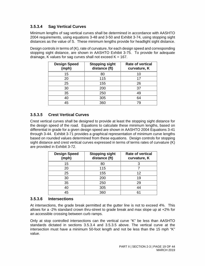
PART II | SECTION 2-3 | PAGE 19 OF 44
MARCH 2019
Sag Vertical Curves Minimum lengths of sag vertical curves shall be determined in accordance with AASHTO 2004 requirements, using equations 3-48 and 3-50 and Exhibit 3-74, using stopping sight distances as the value of S. These minimum lengths provide for headlight sight distance.
Design controls in terms of (K), rate of curvature, for each design speed and corresponding stopping sight distance, are shown in AASHTO Exhibit 3-75. To provide for adequate drainage, K values for sag curves shall not exceed K = 167.
Design Speed (mph)
Stopping sight distance (ft)
Rate of vertical curvature, K
15 80 10 20 115 17 25 155 26 30 200 37 35 250 49 40 305 64 45 360 79
Crest Vertical Curves Crest vertical curves shall be designed to provide at least the stopping sight distance for the design speed of the road. Equations to calculate these minimum lengths, based on differential in grade for a given design speed are shown in AASHTO 2004 Equations 3-41 through 3-44. Exhibit 3-71 provides a graphical representation of minimum curve lengths based on rounded values determined from these equations. Design controls for stopping sight distance and crest vertical curves expressed in terms of terms rates of curvature (K) are provided in Exhibit 3-72.
Design Speed (mph)
Stopping sight distance (ft)
Rate of vertical curvature, K
15 80 3 20 115 7 25 155 12 30 200 19 35 250 29 40 305 44 45 360 61
Intersections At intersections, the grade break permitted at the gutter line is not to exceed 4%. This allows for a -2% standard crown thru-street to grade break and max slope up at +2% for an accessible crossing between curb ramps.
Only at stop controlled intersections can the vertical curve “K” be less than AASHTO standards dictated in sections 3.5.3.4 and 3.5.3.5 above. The vertical curve at the intersection must have a minimum 50-foot length and not be less than the 15 mph “K” value.
PART II | SECTION 2-3 | PAGE 20 OF 44
MARCH 2019
3.6 Other Right of Way Design Elements 3.6.1 Sidewalk The City of Bend in association with the transition plan for City of Bend Americans with Disabilities Act (ADA) Transition Plan for Curb Ramps and Sidewalks in the Public Rights-of-way August 2013 and the 2016 – 2018 ADA Transition Plan for Curb Ramps in Public Rights-of-Way update. The City has developed the following design guidelines and policy in association with the Unites States Code of Federal Regulations (CFR) (See 28 CFR 35). The 2010 ADA Accessibility Standards are guidelines for helping meet Federal ADA requirements set forth in PROWAG. Curb ramps are required for both new construction and most reconstruction projects. Additionally, maintenance operations or approved privately funded (public) improvements may require upgrades, roadway surface alterations or addition of ADA facilities.
Sidewalk construction and location details shall be as shown on the Standard Details. Asphalt sidewalks are not permitted. Asphalt trails may be used in place of sidewalks as planned in the City’s Transportation System Plan. It is not desirable to have two parallel facilities (sidewalk and trail) therefore, when replacing the sidewalk, the trail shall conform and meet all sidewalk requirements as outlined herein.
Sidewalks shall be located within the right-of-way. If design deviations to this location are desired then a request shall be made of the City Engineer. Deviation considerations shall include the review criteria from Chapter 2.2 as well as these specific criteria:
• The centerline of the sidewalk shall not meander more than 35 feet from the street curb line; and
• Where topographical or vegetation limitations require, 15’ public access easements (7.5’ each side of centerline) shall be provided.
• Sidewalk shall be 5-6 feet in width as required by the Bend Development Code.
Obstructions Structures and obstructions including but not limited to fire hydrants, street signs, utilities, utility poles, signal poles, central delivery mailboxes, and individual mailboxes shall not be located in the accessible path of travel portion of the sidewalk.
Horizontal Alignment Sidewalks shall be constructed abutting the property line (back of walk at 6 inches from property line). Designers may meander the sidewalk from the property line when necessary due to topographical or vegetation issues, rather than economical or other design issues.
The sidewalk shall generally follow a smooth and gradual alignment free of sharp angles or bends; horizontal curves shall not be less than 20’ radius.
Vertical Alignment Sidewalk grades shall comply with PROWAG guidelines. Changes in vertical elevation of the sidewalk with respect to the roadway’s running curb elevation can lead to difficulties in achieving ADA compliance with running slopes and ramp slopes.

PART II | SECTION 2-3 | PAGE 21 OF 44
MARCH 2019
The total vertical separation between the top of curb and the top of the sidewalk influences roadside grades and cross-slopes of planter strips.
When curb tight sidewalk is constructed, the total vertical separation between the top of curb and the top of sidewalk shall be zero feet – the sidewalk shall be flush with the curb.
Surface alterations A roadway alteration includes activities such as reconstruction, rehabilitation, resurfacing, widening, and projects of similar scale and effect (See 2010 ADA Accessibility Standards, section 106.5). Maintenance activities such as filling potholes, minor pavement patching, and limited trench cuts for utilities are not typically considered alterations. However, any of these activities that occur within a street level pedestrian walkway (a marked or unmarked crosswalk) may not reduce the path’s accessibility (See 28 CFR 35.133(a). A street level pedestrian walkway (e.g. marked or unmarked crosswalk) is where the pedestrian would cross an intersecting road, regardless if curb ramps are currently present.
Sidewalks Through Driveways Sidewalks shall travel through City Standard driveway aprons at sidewalk grade, with the driveway being segmented by the sidewalk. To maintain their effectiveness, detectable warning surfaces should not typically be used where an accessible route of travel intersects a residential or commercial driveway entrance or within a parking lot. However, the City reserves the right to require detectable warning surfaces at certain high volume commercial entrances that may function like a roadway. The minimum sidewalk width through driveways is 4 feet, zero inches. 3.6.2 Curb Ramps and Crosswalks All required curb ramps must meet the Public Rights-of-Way Accessibility Guidelines (PROWAG) published by the U.S. Access Board. The City, by this reference adopts PROWAG into its standards. Curb ramps are only required where there is a pedestrian walkway (e.g. a sidewalk or trail/path) with a prepared surface that intersects a roadway. Prepared surfaces may include concrete, asphalt, or other compacted materials such as soil and granite. Concrete and asphalt are the two most common prepared surfaces found in Bend. Conditions for curb ramp construction:
1. If any work (new construction or reconstruction) impacts a curb where there is a pedestrian walkway (e.g. a sidewalk or trail/path) intersecting a roadway then a new ramp or replacement of an existing non-compliant curb ramp must be constructed.
2. If any work includes resurfacing through a street level pedestrian walkway (e.g. marked or unmarked crosswalk), even if the work is not the full width of the roadway, curb ramps must be built or reconstructed on both ends of the crosswalk.
3. If any sidewalk work connecting to an existing non-compliant ramp that requires any modification to any portion of the ramp to meet current sidewalk design standards, then the entire ramp shall be reconstructed to current standards.
4. If any utility trench work impacts a curb at a cross walk, with or without a ramp, the replacement of an existing non-compliant curb ramp must be constructed.

PART II | SECTION 2-3 | PAGE 22 OF 44
MARCH 2019
5. If utility trench work does not impact a curb ramp but is “limited to a portion of the pavement, including a portion of the cross walk” replacement of an existing non-compliant curb ramp may not be required (dependent on overall project scope and required pavement restoration limits).
Any Land Use application for new development that includes requirements for sidewalk construction or frontage improvements meeting current City Standards, all curb ramps along the property frontages shall be reviewed for compliance with current standards. Any non-complaint curb ramps along the property frontage must be brought into compliance. This requirement must be included as a Condition of Approval in the Land Use Decision.
Number and Direction of Curb Ramps The City prefers each new intersection to be designed with two (paired) curb ramps per corner allowing for all directions of travel, unless site conditions require modification. These are often referred to as directional ramps. If site conditions prevent the use of directional ramps, the Design engineer must provide documentation to the City Engineer for review and approval as described in 3.6.2.2. An example of “all directions of travel” in this case means six curb ramps at a T or three legged intersection. This would be two curb ramps at each corner (one per crosswalk) and two on the “top of the T” allowing for crossing of both roadways. At a four legged intersection this would be eight curb ramps (two at each corner, one per crosswalk). Each ramp shall run parallel to (in line with) each crosswalk (regardless of if the crossing is marked or unmarked).
Type of Ramps Preferred and Documentation
A perpendicular curb ramp for each crosswalk is the City’s most preferred design because it does not present unnecessary grade changes in the path of travel for pedestrians that are not crossing the roadway. If existing site constraints such as the required use of a “curb tight” sidewalk prevent the use of perpendicular curb ramps, the next most preferred and allowable design options include parallel or combined perpendicular/parallel curb ramps which still provide a separate and distinct curb ramp for each crosswalk. Documentation in writing of existing site constraints preventing the use of a perpendicular curb ramp and instead utilizing parallel or combined perpendicular/parallel curb ramp design must be provided to and approved by the City prior to construction. A single diagonal curb ramp or blended transition (a blended transition in this case is when the entire sidewalk is depressed at the corner and the resulting landing is shared by two crosswalks) at a corner may only be used when significant existing site constraints do not allow two ramps to be installed (one per crosswalk). Documentation in writing of these significant existing site constraints must be provided to and approved by the City prior to construction. To summarize the City’s requirements for selecting an appropriate curb ramp design, the following flow chart is provided:
• Most preferred: Perpendicular curb ramp for each crosswalk (two per corner)
• Parallel curb ramp for each crosswalk (two per corner)*

PART II | SECTION 2-3 | PAGE 23 OF 44
MARCH 2019
• Combined perpendicular/parallel curb ramp (this provides a separate and distinct curb ramp for each crosswalk)*
• Least preferred: Diagonal curb ramps or blended transitions shared by two crosswalks (only allowed with significant existing site constraints that shall be fully documented, provided in writing to and approved by the City prior to construction)
*Allowable only if constraints dictate, such as the required use of “curb-tight sidewalk.” Documentation in writing shall be submitted to and must be approved by the City prior to design and construction.
Existing Physical Constraints Where existing physical constraints make it impracticable for altered elements, spaces, or facilities to fully comply with the requirements for new construction, compliance is required to the extent practical within the scope of the project. If the engineer of record deems the work is not practical due to existing constraints, the City Engineer will decide whether any deviation or claim of impracticality is justified. (For more information on existing physical constraints, see below). A common example of “within the scope of the project” would be when all work related to a project is restricted to one corner of an intersection. In this case the project would only be responsible for providing two accessible curb ramps at this location (regardless of what was present in the existing conditions). The project would not be responsible for constructing new or altering existing curb ramps on the other corners of the intersection outside of the project limits. Existing physical constraints can include, but are not limited to, underlying terrain and topography, right-of-way availability, underground structures, adjacent developed facilities, drainage, or the presence of a notable natural or historic feature.
Design Details Curb ramps must be designed to fit the site and must be detailed on constructions plans. The design must provide sufficient horizontal and vertical control and the drawings annotated to ensure that ramp conforms to federal, state, and local accessibility standards. Curb ramps with corresponding grades and transitions must be designed to ensure proper drainage of the intersection. Grades including running slopes and cross slopes must be noted on each quarter delta of the curb return. The City may require that curb ramps be designed and stamped by a professional engineer as part of any permit application. To assist in the City’s review of plans and for contractors and inspection staff to ensure compliant and quality ramp construction, the following information is required to be shown in plans:
• Running slope (parallel to path of travel) percentage and direction
• Cross slope (perpendicular to path of travel) percentage and direction
• Control points with finished grade and top of curb (where applicable) elevation information*
• Dimensions of features (e.g. length and widths of ramps and landings) *Control points may include throats of ramps, top and bottom of ramps and landings, tie-in points to match existing or other proposed features, and any wings or curb returns.

PART II | SECTION 2-3 | PAGE 24 OF 44
MARCH 2019
Per PROWAG, the absolute legal maximum constructed slopes allowed are: • 8.3%* (or 12:1 run/rise) for a running slope (parallel to the direction of travel);
and • 2.0% (or 48:1 run/rise) for cross slope (perpendicular to the direction of travel).
Since the City recognizes that when curb ramps are constructed in the field some tolerances from the design may occur, designers are directed to use the following maximum design values to ensure the constructed ramps and sidewalks will be below the following PROWAG required absolute legal maximum slopes:
• For running slope (parallel to direction of travel) the maximum design value should be 7.5%*
• For cross slope (perpendicular to direction of travel) the maximum design value should be 1.5%
*Per PROWAG, curb ramps and transition ramps are not required to be longer than 15 feet.
Additional Definitions and Requirements ORS 801.220 defines crosswalks as any portion of a roadway at an intersection or elsewhere that is distinctly indicated for pedestrian crossing by lines or other markings on the surface of the roadway. Where no marked crosswalk exists, a crosswalk is every crossing of an intersection. In general, when a feature in the public right-of-way is altered, the requirements for new construction must be applied to the maximum extent feasible. Any design that does not meet the accessibility requirements for new construction must be documented in writing, submitted to and approved by the City prior to construction. Detectable warning surfaces are required on all accessible curb ramps, and where the pedestrian paths of travel cross intersecting roadways, such as a paved trail intersecting a roadway with no curb. PROWAG refers to this as a blended transition. Detectable warning surfaces must extend for the full width of the curb ramp or blended transition.
Planter Strip The planter strip is that portion of the roadside that is located between the curb and the sidewalk. Planter strips are required to conform to roadside safety requirements in terms of their slope, landscaping, appurtenances, utilities, etc.
The landscaped portion of the planter strip must be a minimum of 5 feet wide, except where the sidewalk meander returns to be adjacent to the curb. In order to prevent sharp re-entrant angles in the landscaped portion of the planter strip, an edge not less than 8 inches long and squared to the curb must be constructed at the juncture of the sidewalk to the curb.
Planter strips must contain street trees when required by the Bend Development Code. Street trees shall conform to the City’s landscaping requirements found in Chapter 12 and sight distance requirements in Chapter 3.3 of this document. Planter strips may be utilized for swales or landscaping and shall conform to the applicable Bend Development Code

PART II | SECTION 2-3 | PAGE 25 OF 44
MARCH 2019
provision. When used for landscaping, the landscaping shall conform to the City’s xeriscape and landscape provisions found in Chapter 12 of this document.
The cross-slope of the planting strip between the curb and the right-of-way must not be steeper than 4H:1V to provide a recoverable roadside slope. All appurtenances, utilities and structures located within the planter strip that are roadside safety obstacles must comply with roadside safety principles of Chapter 1.6 of this document. Obstacles must be located as far from the roadway as possible and be designed with recoverable slopes or breakaway foundations complying with AASHTO “Standard Specifications for Structural Supports for Highway Signs, Luminaires, and Traffic Signals, with interim revisions.”
The planter strip must not contain stairs. Stairs are not allowed to be located within the public way. Deviations to this standard may be submitted to the City Engineer for design standard deviation review per the requirements of Chapter 3.2 of this document.
Exceptions This section identifies exceptions to the ADA requirements. The City’s Transition plan outlines requirements for operation of the ADA program. This design guideline does not set direction of maintenance activities or operational goals outlined in the transition plan. However, when a ramp upgrade or installation is required, it must meet these requirements unless otherwise stated in a project scope or contract.
3.6.3 Transit Facilities Bus stop locations, bus pull-out locations and transit facilities located within the public right-of-way shall be approved by the City Engineer.
When evaluating bus stop locations or a corridor of stops, the impact on roadway operations and safety shall also be considered. Analysis inputs should include: dwell time; bike lane and travel lane blockage effects; transit vehicles ability to enter and exit the flow of traffic; convenience and safety of passengers; and convenience and safety of pedestrians accessing the bus stop.
Transit facilities shall be designed to incorporate roadside safety features by locating benches and shelters far away from the traveled edge of the roadway, as close to the right-of-way line as possible. Deviations in sidewalk alignment to facilitate the installation of transit facilities shall be designed to comply with the horizontal alignment requirements of this chapter. Consideration should be given to using breakaway support features to reduce the crash severity of vehicle run off the road events when elements cannot be located with adequate clearance to the traveled way.
Bus Stop Locations A Transit or bus stop is a designated place along a transit route typically in the street right-of-way where a public transit vehicle stops to load and unload passengers. The following are design guidelines for the locations of bus stops:
• Distance between stops is typically 800 feet;
• Stops are located in areas where passengers have a safe and direct access to sidewalks, walkways and waiting areas;

PART II | SECTION 2-3 | PAGE 26 OF 44
MARCH 2019
• Passengers have access to an accessible route to and from the bus stop and onto the bus;
• Convenient access for pedestrians;
• Analysis and design of safe pedestrian crossings of the roadways are incorporated into bus stop locations;
• A properly developed and located bus stop allows for safe movement by the bus in to and out of the main traffic flow.
Types of bus stop locations 3.6.3.2.1 Far-side Far-Side bus stop is a stop that is located immediately following an intersection and is recommended when:
• Traffic in the direction the bus is traveling is heavier approaching the intersection than leaving the intersection;
• There is high demand for right turns in the direction the bus is traveling;
• The crossing street is a one-way street where traffic flows from left to right;
• The location is one that offers a clear advantage for transit riders by providing improved access to a major destination or to other intersecting bus routes;
• Priority control at the traffic signal is utilized to maintain bus schedules.
3.6.3.2.2 Near-side Near-Side bus stop is a stop that is located immediately before an intersection and is recommended when:
• Traffic in the direction the bus is traveling is heavier leaving the intersection than approaching the intersection;
• The cross street is one-way where traffic flows from the right to left;
• The location is one the offers a clear advantage for transit riders by providing improved access to a major destination or to other intersecting bus routes.
3.6.3.2.3 Mid-block Mid-block bus stop is a stop that is generally located 100 feet or more before or beyond an intersection and is recommended when:
• The distance between intersections far exceed the standard for bus stop spacing;
• Traffic or physical street characteristics prevent siting a stop close to an intersection;
• The bus stop serves large businesses, housing developments, or other significant trip generators.

PART II | SECTION 2-3 | PAGE 27 OF 44
MARCH 2019
Bus Stop Turnouts Bus stop turnouts are not standard for arterial and collector roadways. Design standard deviations review shall consider the following criteria:
• Bus dwell time;
• Dwell time impact on bicyclists; and
• Width of roadway and impact of following vehicles passing bus during dwell time on arterial or collector roadway operations and safety.
When approved, bus turnouts shall be designed in accordance with the current standards set forth in AASHTO.
3.6.4 Driveways The locations of new driveways shall be approved through land use (e.g. part of a master plan, subdivision, or site plan) and through a right-of-way permitting process. Driveways shall be reviewed with the following considerations:
• There is a valid land use approval for the driveway (or it is confirmed that no land use approval is necessary for the driveway in question);
• There is only a single access point to the property;
• The access is to the lowest classified roadway facility abutting the property (alleys are lower classifications than local streets);
• Adequate intersection sight distance for all turning movements in and out of the proposed driveway are provided;
• The driveway meets the following minimum spacing (10 feet apart (bottom of curb drop to bottom of curb drop))
• Maximum distance to an intersection is provided given the lot configuration and site layout;
• Driveways shall not compromise safety and operations; and
• Where a driveway is proposed across the street from another driveway, alley, or street, the path of travel should be aligned, where possible.
Concrete driveway approaches are required on all new construction or reconstruction where sidewalk or curb is existing or proposed. Asphalt driveways are permitted where sidewalk or curb is not existing or proposed, as approved by the City Engineer. New alleys or reconstructed alleys must have a driveway approach at the intersection of the alley and roadway. The driveway approach shall be designed to ensure that all drainage is contained on-site. Design standards deviation requests to consider a curb return rather than a driveway approach may be considered by the City Engineer in accordance with 4.2 and the following specific driveway review criteria:
• The design vehicle for the site is too large to accommodate turns within the standard driveway apron; and

PART II | SECTION 2-3 | PAGE 28 OF 44
MARCH 2019
• All site drainage is still contained on-site.
The minimum sidewalk width through driveways is 4 feet for construction within the City of Bend. The design shall provide sufficient horizontal and vertical control and the drawings annotated to ensure that driveway conforms to federal, state, and local accessibility standards.
3.6.5 Signing No sign shall be designed for or installed within public right-of-way unless it has first been reviewed and approved by the City Engineer or designee.
Street signs and barricades shall be designed and installed according to City of Bend Standards and Specifications, and meet the requirements of the most current edition of the Manual on Uniform Traffic Control Devices (MUTCD) as well as the Oregon Supplements to the MUTCD. This applies to signs and traffic control devices on all streets open to public travel, whether publicly or privately owned or maintained.
To provide appropriate roadside safety, ground-mounted signposts shall be breakaway in compliance with the current AASHTO “Standard Specifications for Structural Supports for Highway Signs, Luminaires, and Traffic Signals, with interim revisions.”
New signs shall be installed, and existing signs modified, to reflect new lane configurations and in coordination with existing or revised pavement markings. Remove and replace signs beyond the project limits as necessary to reflect changes implemented with the project.
Existing signs within project limits that are not in compliance with these requirements in terms of offsets, siting, physical condition, and applicability shall be updated to bring them into compliance.
Plans shall reference signs by MUTCD type, and include designs for all non-standard signs. Designs for standard signs are provided in FHWA’s Standard Highway Signs manual; ODOT’s Sign Policy and Guidelines and the City’s Standard Details include designs for Oregon- and City-specific sign designs not found in the federal manual.
Before any new highway, detour, or temporary route is opened to traffic, all necessary signs and barricades shall be in place. Signs necessitated by road conditions or restrictions shall be removed when those conditions cease to exist or the restrictions are withdrawn. Temporary TRAFFIC CONTROL CHANGE AHEAD signs, installed on wood posts, shall be installed on any project that changes traffic control type.
Placement Sign installations shall not block pedestrian paths of travel in the sidewalk; an ADA-compliant pedestrian access route shall be maintained at all times.
For arterial and collector roadways, the signs shall be visible from, at a minimum, the stopping sight distance of the roadway for the design speed (AASHTO). This requires that street name signs not be placed too far around curb returns on side streets to meet the visibility requirements. Existing and proposed site features shall be reviewed to ensure that there are no existing or proposed obstructions to sign visibility within this required sight distance.

PART II | SECTION 2-3 | PAGE 29 OF 44
MARCH 2019
Signs for private streets at intersections with public streets (i.e. Stop sign/street name sign installations) shall be installed within public right-of-way.
End-of-Road Markers shall be installed on dead-end or stub streets where the pavement ends. Type III barricades are advisable where a higher level of visual cue is desired, such as where the end of roadway precedes a non-traversable slope or major obstruction. Type IV OM4 object markers may be considered on low volume roads.
Type III barricades, with appropriate road closed signage, shall be installed at the end of the traveled way when the pavement continues but travel is restricted beyond a certain point. The barricades shall effectively block traffic. Barricade colors, reflectivity, and design shall conform to the most current edition of the MUTCD with Oregon Supplements.
Horizontal and Vertical Clearance Sign installations shall comply with the most current edition of the MUTCD and City of Bend Standard Details. Vertical and horizontal clearance to the sign face shall be maintained for vehicular and non-motorized traffic.
Sign Design Detailed drawings of standard signs and alphabets are shown in the Federal Highway Administration (FHWA) Standard Highway Signs manual and ODOT Sign Policy and Guidelines, current edition. These guides shall be followed for sign dimensions, colors, messages, letters, numerals, spacing, borders, etc., except as otherwise provided in these City Standards and Specifications.
Drawn-to-scale drawings for nonstandard signs shall be included in the construction plan set for approval prior to fabrication.
Standard post-mounted street name signs are single-sided; signal mast arm-mounted street name signs and central island roundabout street name signs are single-sided. Refer to Standard Drawing R-7, R-7A, R-8 and R-9.
Street Name Signs Street name signs naming both streets shall be installed at each intersection. The signs shall be mounted with their faces parallel to the streets they name.
In business districts and on collectors and arterials, street name signs shall be placed in at least two locations, on diagonally opposite corners so that they shall be on the far right side of the intersection for traffic on the major street. On local streets and residential areas, street name signs shall be placed in at least one location for each intersection.
Street name signs at signalized intersections shall be mounted overhead on signal pole mast arms for optimal viewing. Such signs shall be included on the Traffic Signal Plans. Maximum sign sizes and placement specifications apply; refer to the Oregon Standard Drawings.
Signs for private streets shall be installed on private property, outside of public right of way. Such sign installations shall incorporate a supplemental PRIVATE DRIVE sign mounted below the standard street name sign.

PART II | SECTION 2-3 | PAGE 30 OF 44
MARCH 2019
3.6.5.4.1 Colors and Visibility Public street name signs shall have a white border along the outside edge of the sign and white lettering. The colored background shall be green.
Private street name signs mounted on private property at locations other than intersections with public streets shall include a background color of retro-reflective green, blue, brown, or black, with white retro-reflective lettering. Private street name signs shall be accompanied by a supplemental black on yellow PRIVATE DRIVE sign when installed at intersections with public streets.
School-related signs shall be fluorescent yellow-green.
3.6.6 Pavement Marking/Striping Striping and other pavement markings shall be provided on all arterial and collector streets within City limits. Striping of local streets is not required unless deemed necessary by the City Engineer.
Striping designs shall comply with the current edition of the MUTCD with Oregon Supplements, and City Standards and Specifications. Oregon Standard Drawings TM500-TM503 contain pavement marking line and legend details.
Plans shall show and identify a minimum of 300 feet of existing striping beyond the project limits, to ensure proper tie-in to existing striping. Where project limits occur within 500 feet of existing pavement or striping tapers, limits of striping plans shall be extended to include the full taper. Plans shall show and identify all existing striping and include all striping removal necessary to implement new striping as shown.
Plans shall reflect the following City standards:
• Left turn lane transitions - where painted center medians transition to left turn lanes, gaps are preferred over reverse curves.
• Turn lane storage shall reflect 95th-percentile queues as determined in a queuing analysis, which shall be submitted with the striping plan.
• The City does not use raised pavement markers (RPM’s) on the roadway surface, due to snow removal operations.
• Leading ends of raised medians and islands shall be painted yellow or white as applicable, in conformance with the MUTCD. Reflective RPM’s of the same color shall be placed on the top of the curb around the leading ends of medians and islands. In addition, surface-mounted tubular markers shall be installed as shown in City’s Standard Detail for median end treatments.
• Where a fixed obstruction is present within a paved roadway, such as a raised median preceded by a painted median or two-way-left-turn-lane, the approach area shall be marked with Transversee diagonal lines and no passing lines, unless otherwise provided in Section 3 of the MUTCD.
• Marked crosswalks shall be provided at all signalized intersections and at other locations according to the City’s Standard Operating Policy. Crosswalks shall not be marked at uncontrolled locations without City Engineer approval.

PART II | SECTION 2-3 | PAGE 31 OF 44
MARCH 2019
3.6.7 Curb Painting Curbs shall be painted yellow for a total of 20 feet approaching a stop sign. Curbs shall be painted red for a total of 20 feet at fire hydrants, 10 feet on either side of the hydrant.
Paint shall be high performance latex, designed for streets and parking lots. The paint must meet federal specification TT-P-01952E Type II. The paint should be suitable for surfaces such as Portland cement concrete, bituminous cement concrete, asphalt, tar, and previously painted areas of these type surfaces.
Colors must meet Traffic Standards for the Traffic Yellow and OSHA Safety Red. Examples of common colors and their FED-STD-595 color chip Yellow – #33538 and Red – #31136.
The curb must be prepared for the paint application. Any organic material near the curb shall be removed, existing loose paint shall be scraped off, and oil spills shall be cleaned.
Acceptable methods of cleaning the curb surface are high pressure washing and/or hand scrubbing using clean water and clean water to rinse.
Surface shall be clean and completely dry before application of paint starts.
Curb shall be painted from the top seam of the curb (sidewalk or planter strip edge) to a point even with the driving surface and within the limits specified by the City of Bend and its representative.
Paint areas shall be protected (masked, taped or both) to prevent dripping or over spray of paint onto the sidewalk or street surfaces and to provide clean/straight edges.
Apply the paint per manufacturer’s specifications, or typically when the weather is between 60 and 80 degrees Fahrenheit and overnight temps do not drop below freezing for optimal adhesion. Choose a day when the weather is dry and when the wind is not blowing to avoid the wind carrying the paint and to prevent blowing debris onto the freshly painted surface.
3.6.8 Mailboxes Mailboxes located within roadway rights-of-way are subject to these Standards and Specifications. Roadside design safety aspects shall be considered. Fatal crashes have occurred within the City of Bend due to vehicles striking mailbox fixed object hazards that did not provide breakaway supports. Foundations and support structures of individual and cluster postal delivery boxes shall meet the current AASHTO “Standard Specifications for Structural Supports for Highway Signs, Luminaires, and Traffic Signals, with interim revisions.”
The mailbox shall be firmly secured to the post to ensure that the impact of a vehicle does not loosen the box which could then become a flying object hazard.
Mailboxes shall not require that users cross an arterial or collector roadway. Mailboxes shall be located on the users side of arterial and collector roadways.
For all new and reconstructed roadway projects, rural delivery mailbox styles shall be considered for consolidation into cluster postal delivery boxes.

PART II | SECTION 2-3 | PAGE 32 OF 44
MARCH 2019
The location of cluster postal delivery boxes shall be shown on the engineered plan submittal drawings for review and approval. The United States Postal Service will approve the location of cluster postal delivery boxes.
An accessible pedestrian path of travel must be designed and constructed to the mailbox per PROWAG requirements.
An accessible pedestrian path of travel must be maintained on sidewalks adjacent to cluster boxes per PROWAG standards.
Cluster postal delivery boxes shall not be located on arterial and collector streets, unless otherwise approved by the City Engineer. Their location shall be shifted to nearby and convenient local streets. When locating the cluster postal deliver box care should be taken to locate it in an area that minimizes impact on abutting properties.
The back edge of the sidewalk shall smoothly meander back from the central delivery mailbox station to provide a 5-foot wide unobstructed pathway. The edge of the mailbox shall comply with the City’s Clear Zone Requirements of this document.
3.6.9 Illumination Streetlights are required at all street intersections with collectors and arterials, including private street intersections with collectors and arterials. This requirement does not extend to alley intersections. Requests for street lights at other locations shall be reviewed in conformance with the Transportation Division’s Standard Operating Procedure and installed only with City Engineer approval.
Separate street lighting plans are not required for most projects although proposed streetlights shall be shown on plan and profile or utility sheets. Plans must include the following:
• Proposed pole locations shall comply with the City’s Roadside Safety requirements of this document.
• Power supply shall be provided via underground wiring and conduit systems conforming to power company requirements.
• Fixtures shall be cut-off fixtures to minimize light pollution and up-lighting.
• Light poles and fixtures shall be approved and maintained by the power company.
On private development projects, all costs of installation shall be borne by the developer. The City will pay for ongoing power and maintenance expenses for public street lighting. Ongoing expenses for private street lighting (including power costs) shall be borne by the developer or homeowner’s association.
Decorative lighting will not be permitted without special approval and maintenance agreements signed by the City Engineer.
The City encourages the use of energy-conserving luminaire fixtures. Proposed equipment must be approved by the City Engineer and the power company.

PART II | SECTION 2-3 | PAGE 33 OF 44
MARCH 2019
3.6.10 Drainage Roadways shall comply with the storm drainage requirements of Chapter 6 of this document.
The standard drainage inlet feature for arterials and collectors shall be curb inlet when bike lanes are present.
3.6.11 On-Street Parking On-street parking shall be designed to accommodate parking parallel to the curb. There may be instances when head in or back in angle parking is desirable. The City will consider these instances on a case-by-case basis.
3.6.12 Traffic Calming Devices Traffic Calming Devices in the context of the standards means specific traffic calming devices designed to restrict travel speeds over or through a specific location. Traffic calming devices include neighborhood traffic circles (which are very specifically not roundabouts), speed humps and raised pedestrian crossings. Within the context of this document, traffic calming devices are not curb extensions, medians, roundabouts, signals, stop signs or cross-walks as these are typical operational or cross-sectional elements of roadway design.
City standards provide for arterial and collector roadway designs that are reflective of their abutting land use zoning and are sensitive to their surrounding context. The installation of traffic calming devices are not allowed on arterial and collector roadways due to their negative impacts on emergency vehicle routing, maintenance issues, and truck circulation issues.
Traffic calming devices are restricted in use to local residential streets or local commercial streets. Requests for traffic calming devices during the land use process may be evaluated for local residential streets. However, their use shall be approved by the City Engineer and shall not be installed without this approval. Consideration shall be given to emergency vehicle routing.
Currently the City allows traffic circles and raised speed tables or raised pedestrian crossings as traffic calming devices on local streets. Their designs shall conform to the standard drawing for these elements.
3.7 Temporary Traffic Control The primary function of temporary traffic control is to provide safe and efficient movement of all road users through or around work zones while protecting those within the work zone. The City requires temporary traffic control, based on a City-approved Traffic Control Plan, for all improvement projects, public or private, performed within, or impacting travel on, public right-of-way.
Traffic Control Plans (TCP’s) shall be provided for review with the ROW permit submittal.
Traffic Control Plans shall be developed according to the following:
TCP’s must be in substantial compliance with:

PART II | SECTION 2-3 | PAGE 34 OF 44
MARCH 2019
• The Manual on Uniform Traffic Control Devices (MUTCD), current edition; see Chapter 6. http://mutcd.fhwa.dot.gov/pdfs/2003r1r2/ch6a_e.pdf
• The Oregon Supplements to the MUTCD
• The Oregon Temporary Traffic Control Handbook for Operations of Three Days or Less (OTTCH) when applicable http://www.oregon.gov/ODOT/HWY/TRAFFIC-ROADWAY/docs/pdf/OTTCH_06.pdf
Additional Resources:
• Oregon Standard Drawings, TM 800 series – contains additional information and details for traffic control scenarios not found in the OTTCH. http://egov.oregon.gov/ODOT/HWY/ENGSERVICES/traffic_drawings.shtml
Non-project related TCP’s need not be CAD-drawn, but must be legible and scaled or dimensioned to clearly indicate relevant spacings and distances. Figures from the references listed in this Chapter may be utilized whenever applicable, and customized as necessary. At a minimum, TCP’s must show the following:
• Existing features within 300 feet of the work area (# of lanes, turn lanes or medians, bike lanes, sidewalks, stop signs, traffic signals). (Extend to 500 feet if work area is within 500 feet of a traffic signal.)
• All proposed Traffic Control Devices, including signs, cones/tubular markers, barrels, barricades, etc. Identify devices by MUTCD types or Legends/Colors, and size.
• Posted speed. Work zone area component lengths and device spacings are dependent upon prevailing speeds of area traffic. Speed signs for speeds less than the permanently posted or statutory speeds may only be implemented with a Temporary Speed Zone Reduction approved by the City Engineer.
• Spacing of all Traffic Control Devices. See Section 1.9 of the Oregon Short Term Traffic Control Handbook
• Lengths of the Temporary Traffic Control Zone Area components, including the Advance Warning Area, Transition Area, Activity Area (Buffer Zone+Work Zone), and Termination Area. See Section 1.9 of the Oregon Short Term Traffic Control Handbook or Section 6C of the MUTCD for required lengths.
• Proximity to nearest intersection. Site specific drawings are required for all work zones within 500 feet of a signalized intersection. Note that Oregon law prohibits flagging through an operating traffic signal (except for uniformed traffic control officers). Lane reductions through an operational, signalized intersection may be permitted on multi-lane facilities.
• Accommodations for non-motorized vehicles and pedestrians within a work zone must be provided – See Section 1.3 of the OTTCH. A minimum 4-foot wide path of travel must be maintained on all pedestrian or bicycle ways left open to users. Closures of pedestrian ways and bicycle lanes must be clearly indicated, and users diverted upstream at appropriate locations. Signs used shall be MUTCD-compliant.
• Existing traffic control devices, including stop signs and traffic signals, within 300 feet of the work area. Detour signing must show each proposed sign, and

PART II | SECTION 2-3 | PAGE 35 OF 44
MARCH 2019
include signing adequate to direct motorists through the complete detour route and back to the original roadway. Detours shall be used only with an approved Street Closure Permit approved by the City Manager.
Modifications to approved traffic control shall be made during construction, if deemed necessary and directed by the City Engineer.
Temporary Traffic Signals - Plans for temporary traffic signals shall include the same information required for permanent installations.
Traffic Signal Removal Plan/Traffic Signal Staging Plan – such plans, when deemed necessary by the City, shall be prepared in the same format and including the same information referenced above.
3.8 Pavement Restoration Requirements 3.8.1 Grades The City of Bend establishes a “Grade” based pavement cut standards system developed on the date of construction, the last qualifying pavement treatment applied and the Pavement Condition Index (PCI) rating of a pavement. These standards will be in effect for any City roadway from initial construction or from the time the most recent qualifying pavement treatment was applied. The PCI and road classification (Arterial, Collector or Local road) will determine which Grade must be used. Grade 1 - Pavement Cut Restriction Standard (PCI 100-60, < 5 years): Pavement cuts will only be allowed on an emergency basis or through the wavier process defined in Part I Section 2. No planned or permitted cuts will be allowed when these standards apply. If pavement cutting is necessary for emergencies, pavement restoration will be at the direction of the City Engineer and may include a full width restoration. Grade 2 – Full Standard (PCI 100-60, > 5 years): Pavement cuts must be full depth and extend twelve inches (12”) beyond the nominal trench edge longitudinally and Transversely (Standard Drawing R-10) and be a minimum of four (4) feet in width. Pavement cuts must be at lane and skip lines. Transverse trenches (perpendicular to the center line) that are less than 20’ (inside edge to inside edge) apart shall be patched as one patch. Restoration must extend from curb to fog/bike lane line (5-7’ from curb); curb to centerline (if cut is past fog/bike lane line) and curb to curb (if past centerline). Grade 3 - Modified Standard (PCI 59-40): Pavement cuts must be full depth and extend twelve inches (12”) beyond the nominal trench edge longitudinally and Transversely (Standard Drawing R-10) and be a minimum of four (4) feet in width. Pavement cuts must be at lane and skip lines or center of traveled lanes. Transverse trenches (perpendicular to the center line) that are less than 20’ (inside edge to inside edge) apart must be patched as one patch. Restoration must extend from:
• Curb to fog/bike lane line (5-7’ from curb);
• Fog/bike lane line to center of traveled lane;
• Center of Traveled lane to center line;

PART II | SECTION 2-3 | PAGE 36 OF 44
MARCH 2019
• Fog/bike lane line to centerline; or
• Curb to curb (if past centerline). All pavement restoration must be shown on the permit plans and approved prior to construction. Half lane improvement are on a case by case basis and as approved. T-Cut Standard (PCI 39-0): Pavement cuts must be full depth and extend twelve inches (12”) beyond the nominal trench edge longitudinally and Transversely (Standard Drawing R-10) and be a minimum of four (4) feet in width. Applicable standards based on Grade (number of years since last qualifying pavement treatment) and City Street Classification is established in the following table: TABLE 1- RESTORATION REQUIREMENTS BY CLASSIFICATION AND TIER
Classification PCI 100 - 60 < 5 years
PCI 100-60 PCI 60-40 PCI 40 - 0
Local Grade 1 Grade 2 Grade 3 T - Cut
Collector Grade 1 Grade 2 Grade 3 Grade 3
Arterial Grade 1 Grade 2 Grade 2 Grade 3 Grade 1 - Pavement Cut Restriction Standard; Grade 2 - Full Standard; Grade 3 - Modified Standard; T - Cut Standard (ACP Only)
Note: Proposals to deviate from the standards described above may be allowed at the discretion of the City Engineer and will require approval in advance by the City Engineer. See exemption process described below. During the permit review process, the City Engineer will determine the applicable standard based on the above table. (See figures 1-9 attached)
3.8.2 Permits As part of obtaining a Right-of-Way permit per Bend Code, Chapter 3.40, Permittee must submit a complete application to Community Development Department for review and approval. A Right-of-Way application is available on the City website. The City Engineer will determine the restoration requirements in accordance with these Standards. The Permittee must provide the City Engineer at least twenty-four (24) hours notice prior to completing final restoration to allow for inspection. The permittee shall notify the City within 48 hours after completion of the work (3.40.025). Warranty period will not begin unless the final inspection has been completed. Permittee is responsible for all work until the permit is closed and the warranty period begins.
If the City Engineer determines, in the City Engineer’s discretion, that previous violations of these Standards exist, future construction work may be disallowed until the Permittee has fulfilled all obligations. Written notification by the City Engineer will be sent prior to this action.

PART II | SECTION 2-3 | PAGE 37 OF 44
MARCH 2019
3.8.3 Responsible Party The Permittee shall be responsible for all construction and warranty requirements of these standards even when the work is done by a Permittee-retained contractor.
3.8.4 General Requirements Materials must comply ODOT Standards and specs and as amended by the City of Bend’s Standards and Specifications.
a. All patching materials and construction requirements not addressed in this document must conform to the City’s Special Provisions Section 00744.
b. To the extent Controlled Low Strength Material (CLSM aka CDF) is required for a particular repair, the Permittee must follow ODOT Standard Specification, Section 00442 – Controlled Low Strength Materials.
3.8.5 Pavement Sections Pavement Sections must meet the pavement design standards in Section 11.4 and comply with the following standards, or as specified in a stamped geotechnical report as approved by the City Engineer:
a. Alleys shall be 4 inches of pavement and a minimum of 6 inches of base rock. b. Local roads shall be 4 inches of pavement and a minimum of 6 inches base
rock. c. Collectors shall be 6 inches of pavement and a minimum of 8 inches of base
rock. d. Arterials shall be 8 inches of pavement and a minimum of 10 inches of base
rock. 3.8.6 Full, Modified, and T-Cut Patching Standards Patching must comply with the following standards:
a. Longitudinal cuts that extend through multiple grade classifications require discussion with the City Engineer to determine the appropriate patching approach. In principle, each road section will be patched according to the applicable standard and grade in which it is ranked; however, the City retains the right to require a higher level grade at its discretion.
b. For all full depth asphalt repairs on local roads, the minimum asphalt thickness
shall be 4 inches, or match the existing depth of asphalt, whichever is greater.
c. Existing base rock disturbed within full depth asphalt repairs must be re-compacted prior to paving. For trench backfill requirements Bend Standard Specs. (see Standard Drawing R-10)
d. All cold-planed surfaces must be swept and kept clean at all times. All cold-planed materials must be removed and disposed off-site at the cost of the Permittee.

PART II | SECTION 2-3 | PAGE 38 OF 44
MARCH 2019
e. If a new patch adjoins an existing patch, the existing patch will need to be replaced up to 20 feet from the edge of the new patch. This will be on a case by case basis and will be at the discretion of the City Engineer.
f. If any part of the excavation, patch or damaged area intrudes into an adjacent lane, that lane must also be replaced.
g. New patches adjacent to any existing patch must be combined into one patch if there is less than 4 feet separation.
h. When two (2) or more patches on the same project are created within twenty (20) feet of each other (inside edge of trench to inside edge of trench), they must be incorporated into a single patch at the expense of the Permittee. The total number of street cuts should be kept to a minimum. If there are three or more street cuts within a block every effort must be made to combine all three into one patch. It is at the discretion of the City Engineer to determine the final pavement restoration limits of a project.
i. All restoration shall be shown on approved permit plans; otherwise the grade standards apply in full.
j. Pavement cuts must be straight and clean and must be either parallel or perpendicular with respect to the travel lane. No jagged, broken or undermined edges will be allowed unless otherwise approved by the City Engineer.
k. All pavement cuts shall be sealed hot crack seal methods. Hot crack seal must
be consistently applied throughout, four (4) to six (6) inches in width.
l. Contractors must use ODOT approved release agents and tack when placing multiple lifts of ACP.
m. The top lift of asphalt for all longitudinal repairs with a length that exceeds thirty (30) feet must be placed using a paving machine with a screed or an asphalt spreader box.
n. The completed surface of all courses must be of uniform texture; smooth,
uniform as to crown and grade and free from defects. The completed surface of the wearing course must not vary more than one-quarter (¼) inch from the lower edge of a twelve (12) foot straightedge placed parallel to the centerline. Tolerance exceptions and corrective measures due to existing roadway conditions or other reasons must be approved by the City Engineer.
o. All areas outside of the travel lanes or shoulders that are affected by the work must be restored to their original condition.
3.8.7 Traffic Control Permittee must use Section 3.7 for all traffic control.
PART II | SECTION 2-3 | PAGE 39 OF 44
MARCH 2019
3.8.8 Pavement Cut Restriction (Exception Process) After any street has been constructed, reconstructed, paved or overlaid by the City, the pavement surface must not thereafter be cut or opened for a period of 5 years or as directed by the City Engineer or Director of Streets & Operations. It is understood that field conditions or emergencies may warrant an exception to this Policy. However, the exception process in NO WAY obligates the City to allow cutting or opening the Street Cut Restriction Street, and any such decisions are at the City’s discretion.
A utility desiring to perform work in Street Cut Restriction streets must schedule a meeting with City staff prior to submittal of a permit application. If an exception is granted, the Private Development Engineering Department will make a concerted effort to protect the integrity of the pavement structure, and to ensure a high quality replacement patch or overlay. Additional restoration requirements and extended limits will apply.
When granting exceptions to this policy, the Streets Director or City Engineer may impose conditions determined appropriate to insure the rapid and complete restoration of the street and the surface paving.
Valve and manhole repairs must be exempt from the patching requirements of these standards. Valve and manhole patching requirements must be in accordance with City Standards. All warranty and construction requirements must be met. No longitudinal construction joints must be allowed in the wheel path.
Potholing to find utilities must be exempt from patching requirements of these standards. To be exempt, it is preferred that all potholes are cut with a core/hole saw. If a larger pot hole is required the pavement cuts must be less than two (2) feet square with no joints in the wheel path and must be backfilled with CLSM or other City approved fill from twelve (12) inches above the utility to bottom of asphalt. Core holes must be hot patched in the existing pavement.
City capital improvement projects will be subject to testing and warranty requirements that are established under the applicable public procurement contracts.
An exception from the street cut restrictions standards may be granted if the City Engineer determines that impacts to vehicle, bicycle, and/or pedestrian traffic would negate the public benefit of this standard.
Exception Request Permittee may seek an exception of these Standards as follows:
a. Permittee must submit an exception request to the City Engineer identifying the proposed project, the impact the project will have on the roadway, the timeline for completion and explaining how all alternative solutions including avoidance have been exhausted.
b. A meeting with the City Engineer to discuss the project may be required
and the City may request additional information.
c. The City Engineer must accept or deny any such request. If a request is accepted, the City Engineer may attach conditions of approval that require additional restoration of the area affected and/or special

PART II | SECTION 2-3 | PAGE 40 OF 44
MARCH 2019
inspections, the cost of which shall be borne by the Permittee.
3.8.9 Permits for Non Street Cut Restriction Streets and Street Cut Restriction Streets with Approved Exception No excavation or tunneling must be performed under any area within public rights-of-way prior to first obtaining the applicable permit from the City (permits for emergency work may be issued after the fact per this policy).
Applications for utility permits must be made on forms provided by the City. The applicant must describe the purpose, location, and size of the anticipated construction project (work), the name of the person/firm performing the actual work, and the name of the person/firm for whom the utility work is being performed. The application must be endorsed by the person/firm for whom the work is being performed or the person’s/firm’s agent. By signing the application, it is understood that the person/firm performing the utility work will comply with the requirements of this policy and any conditions imposed upon the work.
Depending on the impact to traffic, pedestrians, businesses or residents, public notification plans (signs, advertisements, flyers, public service announcement, etc.) may be necessary and submitted as part of the permit application. It is the responsibility of the permit applicant or the duly authorized representative to coordinate with all affected neighbors. A pedestrian detour route shall be clearly delineated whenever sidewalks are obstructed.
Emergency utility or service lateral repair work necessary for the immediate preservation of life or property is acceptable; provided that any person making such emergency repair work they call for emergency locates. Permittee must notify the City Engineer of emergency repairs not later than the next business day. The ROW restoration for such emergency repairs must be in conformance with the criteria stated in this policy. Note, work necessary to locate faulting utilities, conduits or pipes during the emergency situation is considered part of the emergency repairs. Permittee must make every reasonable effort to restore the roadway quickly.
When the City Engineer determines that traffic conditions, safety or convenience of the public necessitates ROW utility or service lateral construction and repair be performed as quickly as possible, the City Engineer will require the permittee to provide adequate personnel, equipment, and facilities on a 24-hour basis such that the utility or service lateral work be completed as soon as practicable. This may include, but is not limited to, flaggers, temporary traffic control signs and devices, lighting, etc. The permittee must be responsible for the cost of providing the necessary personnel, equipment, and facilities.
If work is being performed within Highway 20 & 97 (including Parkway 3rd St and Greenwood), coordination with Oregon Department of Transportation (ODOT) may be necessary and the applicant must comply with their requirements for all work solely in the ODOT jurisdiction. For any work in that is jointly permitted, the utility/permittee must provide a copy of the ODOT permit to in conjunction with the City’s permit application.
3.8.10 Special requirements for Concrete Roads All concrete road cuts must be pre-approved before beginning work (except in the case of an emergency situation). Concrete roads must require full panel replacement unless approved otherwise by the City Engineer. All concrete joints must require an approved tie

PART II | SECTION 2-3 | PAGE 41 OF 44
MARCH 2019
bar and dowel retrofit. Depth of concrete replacement must match the existing thickness or as directed by the City. Care must be made not to undermine the existing panels. If the adjacent panels are disturbed or damaged, they also must be replaced at the City Engineer’s direction. All joints must be sealed with material approved by the City Engineer. Where concrete roads are overlaid with asphalt, the concrete must be replaced as described above and asphalt portion of the cut must be constructed according to the pavement standard.
3.8.11 New Development These standards are minimum standards applicable to all cuts made in existing roadways. For new development, additional requirements may apply. Contact the Community Development Department for specific additional requirements.
3.8.12 Temporary Pavement Restoration Pavement must be restored with temporary patches before the road is reopened to traffic as defined below. The Permittee must maintain the temporary patch until the patch has been permanently restored. Gravel surfacing is not acceptable as a temporary patch.
An immediate patch may be used to open the roadway to traffic. Immediate patches may include the use of steel plates with signs or be a minimum of two (2) inches thick cold mix asphalt on two (2) inches thick crushed surfacing. Immediate patches will only be allowed while work is being completed and must be replaced with an interim or permanent patch within seven (7) days after placement. Steel plates must be pinned and ramped with cold mix asphalt. At the direction of the City staff or City Engineer, Steel plates may not be used from November 1st to the end of March 31st. Higher classification roads are on a case by case basis. Steel plates may only be used for less than 5 working days.
When a permanent patch cannot be completed within seven (7) days of an immediate patch, an interim patch must be used to keep the roadway open to traffic. Interim patches must be a minimum of two (2) inches thick ACP on two (2) inches thick crushed surfacing. Interim patches must be replaced with a final patch within thirty (30) days after placement.
Material exceptions may be requested in the event that the ACP Plants have shut down for the season or at the discretion of the City Engineer. Material exception forms must be submitted with the final inspection. Permittee is responsible for making final restoration within 45 days of the ACP plants opening for the season or as directed by the City. Permittee must submit photo documentation, and street location of all street cuts with material exceptions 5 days prior to completing the work
3.8.13 Testing and Warranty Requirements ACP testing must be in accordance with Bend Standards and Specifications. Patches greater than 8’ in width will require density testing per the Bend Standards and Specifications and ODOT Standards and Specification (current adopted version). The City reserves the right to require density testing on a case by case basis if field observations indicate minimum compactive efforts are not being achieved as required in the Bend Standards and Specification.
Pavement restoration on roadways under all pavement cut standards will have a minimum warranty period of one year and up to (2) years. The patch must be repaired if necessary until the warranty has passed.

PART II | SECTION 2-3 | PAGE 42 OF 44
MARCH 2019
All warranties will become void if the road receives a qualifying pavement treatment within the patching limits. Qualifying pavement treatments include the following but are not limited to: Mill and overlay, removal and replacement, thin lift overlay, large area patches half a block in length, and half a lane in width or full street reconstruction. Slurry seals, chipseals, and fog seals are not considered pavement treatments; they are considered a maintenance treatment.
All warranty work requires that a City inspector be on site. The Permittee must be required to coordinate inspection with the City Engineer.
The following minimum defects identified by the City Engineer must be covered by warranty (but not limited to):
a. Sunken pavement patches greater than or equal to one-quarter inch (1/4”) (measured by a twelve foot (12’) straight edge).
b. Surface raveling or oxidation due to deficiencies with the asphalt material. c. Poor workmanship. d. Inadequate compaction per Bend Standards and Specifications.
Notice of Repairs
e. If emergency repairs are needed due to safety concerns, the Permittee must immediately make such repairs and give notice to the City Engineer.
f. For non-emergency repairs on arterial or collector streets, the Permittee has forty-eight (48) hours in which to make such repairs from time of verbal notice by the City Engineer. For residential streets, the Permittee has up to seven (7) days to make such repairs.
g. The City may undertake the repairs if not completed within the specified timeframes above. The City Engineer must notify Permittee of non-compliance and Permittee must make all identified repairs within two (2) business days of notification of noncompliance. Repairs involving public safety maybe made by the City without notice. Permittee will be assessed all costs associated with the City performed repairs, plus fifteen percent (15%) overhead fees.
h. If repairs are made other than seam sealing to the warranted patch, a new warranty will be implemented for the new patch.
3.8.14 No Dig/Trenchless Technology To minimize damage to road surfaces and other surface infrastructure, implementation of no dig/trenchless technology is the preferred method for most utility work.
Trenchless Technology Plan Requirements Applicants for work in the ROW planning to use trenchless technology must submit plans prepared by a qualified professional. Any qualified professional, as defined in this policy, experienced in trenchless utility installation may prepare plans for simple work. Typical “simple work” includes borings of 100’ or less perpendicular to street alignment and borings of 200’ or less parallel to road and sidewalk surfaces. For longer distances, the applicant must meet with Department staff to discuss the proposed operations. The City Engineer may require the plan to be prepared by a qualified registered civil engineer,

PART II | SECTION 2-3 | PAGE 43 OF 44
MARCH 2019
geotechnical engineer or geological engineer licensed in the State of Oregon and require additional studies or information than those required for “simple work”. The plans for “simple work”, at a minimum, must address/consider the following:
a. The proposed bore path (bore plan and profile must be provided) should be planned to allow sufficient room from other utilities or structures for workers to perform maintenance or operations on adjacent utilities. There must be a 5-foot minimum horizontal and 18-inch vertical separation between the proposed utility and City sewers or as otherwise directed. However, additional separation may be required depending upon depth of new utility installation, environmental factors, and engineering conditions.
b. The locations of other utilities within or adjacent to the proposed bore path (within 5 feet) must be shown. Include proposed potholing locations.
c. In preparing the plan, location of other structures such as manhole covers, valve box covers, meter boxes, telephone and cable television boxes, electrical transformers, conduit, or droplines from utility poles, pavement patches, previous locator markers, heating oil tanks, utility vaults, and sewer lateral cleanouts must be considered.
d. Include pavement restoration details (as needed) according to this policy. This includes repair of borehole entry pits and potholes.
Drilling Fluid Handling The trenchless technology contractor must contain, handle, and dispose of drilling fluids in accordance industry and Oregon Department of Environmental Quality standards. Excess drilling fluid must be confined in a containment pit at the entry and exit locations until recycled or removed from the site. Precautions must be taken to insure that drilling fluid does not enter roadways, streams, municipal storm or sanitary sewer lines, and/or any other drainage system or body of water. Unintended surfacing of drilling fluid must be contained at the point of discharge and recycled or removed from the site. Drilling fluids that are not recycled and reused must be removed from the site and disposed at an approved disposal site. Any damage as a result of using Trenchless Technologies is the sole responsibility of the permittee.
Settlement/Heaving Monitoring Trenchless technologies must be performed in a manner that will minimize the movement of the ground in front of, above, and surrounding the boring operation; and will minimize disturbance of the surface above and in the vicinity of the boring. The applicant must be responsible for the repair to City infrastructure resulting from heave or settlement caused by the use of the trenchless technology. All operations must stop immediately whenever a vertical change in elevation of ½-inch or more, or any surface disruption is observed. The permittee must then immediately report the amount of settlement to the Engineering Inspector, Street Department or Utility Department.
Trenchless Technology Operations Guidelines All construction work must be performed in accordance with City requirements and industry standards. The permittee must ensure that all cleanup and restoration is in compliance with the City requirements for right of way restoration. In some cases determined by the Department, the permittee will televise, in the presence of Department staff, the City stormwater and wastewater components within five feet parallel to boring activity or crossed by the boring activity.

PART II | SECTION 2-3 | PAGE 44 OF 44
MARCH 2019
Compliance As part of the notice of noncompliance, the City Engineer will include a notice to comply within five (5) working days or all future permits may be denied until the problems have been corrected. A meeting must be arranged with the City Engineer and a plan of action to prevent future noncompliance must be presented before issuance of any new permits. Noncompliance Activities include:
a. Failure to obtain a permit. b. Failure to maintain temporary patches. c. Failure to make permanent repairs. d. Failure to make emergency repairs. e. Failure to make warranty repairs. f. Failure to inform the City of asphalt completion date. g. Failure to follow traffic control measures, as required. h. Failure to meet specified timeline for any repairs.

PART II | SECTION 2-4 | PAGE 1 OF 22
MARCH 2019
SECTION 2-4
Sanitary Sewer Systems
Table of Contents 4.0 Sanitary Sewer Systems ....................................................................................... 3
4.1 Sewer Main ........................................................................................................ 4
Depth ............................................................................................................ 5
Minimum Diameter ....................................................................................... 5
Flow Calculation ........................................................................................... 5
Peak Factor (Domestic Flows Only) ............................................................. 7
Line Diameter and Velocity ........................................................................... 7
Minimum Grade (Gravity) ............................................................................. 7
Inverted Siphons ........................................................................................... 8
Flows in Pressure Sewers ............................................................................ 8
Minimum Velocity ......................................................................................... 8
Maximum Velocity ........................................................................................ 8
Pressure Sewer Appurtenances ................................................................... 8
Waterline Crossings ..................................................................................... 8
Marking Tape and Locate Wire .................................................................... 9
Materials ....................................................................................................... 9
Construction ............................................................................................... 10
Septic System and Municipal Sewer Extensions ........................................ 10
Sewer System Extension Requirements .................................................... 10
4.2 Manholes (Gravity) ........................................................................................... 11
Manhole Placement .................................................................................... 12
Manholes (Pressure to Gravity Sewer) ....................................................... 12
Pressure Sewer Manholes ......................................................................... 12
4.3 Sewer Services ................................................................................................ 12
Cleanouts ................................................................................................... 13
Sample Manhole ......................................................................................... 13
Sample Manholes on Pressure Sewer Systems ........................................ 14
4.4 Sewage Pump Station Design .......................................................................... 14
Wetwells ..................................................................................................... 15
Pumps ........................................................................................................ 17
Reliability and Redundancy ........................................................................ 18

PART II | SECTION 2-4 | PAGE 2 OF 22
MARCH 2019
Telemetry and SCADA ............................................................................... 18
Pump Control Panels .................................................................................. 19
Electrical Enclosure .................................................................................... 19
Hydrogen Sulfide Protection ....................................................................... 21
Station Access ............................................................................................ 21
Station Fencing ........................................................................................... 21
Force Main Cleanout .................................................................................. 22
Flow Metering ............................................................................................. 22
Bypass System ........................................................................................... 22
Safety Systems ........................................................................................... 22
Lift Station Standards ................................................................................. 22

PART II | SECTION 2-4 | PAGE 3 OF 22
MARCH 2019
4.0 Sanitary Sewer Systems Minimum design standards for sewer facilities are defined by the Oregon Department of Environmental Quality (DEQ) regulations as detailed in the appropriate Oregon Administrative Rules (OAR), Division 52. City of Bend Design Standards may be more stringent. In cases where the City of Bend Standards are different from the requirements specified by DEQ, the City of Bend Design Standards will be used. In cases where the City of Bend lacks a design standard, designers shall refer to OAR Division 52, Appendix A – Sewer Pipelines, and OAR Division 52, Appendix B – Raw Sewage Lift Stations, for detailed criteria.
The City of Bend requires gravity sewers. The City has made this requirement due to the expense of long term operational and maintenance costs associated with non-gravity sewer systems. This has been evaluated in the City’s Collection System Master Plan (CSMP) and will continue to be evaluated in future updates of the CSMP. In places where a gravity solution is not possible, two solutions exist, pressure sewers, and a regional pump station with force main. Regional pump stations will be determined through the City’s CSMP. Where a regional pump station is defined in the CSMP, all sewer flowing to the wet well will be by gravity. No pumping from one pump station to another pump station will be allowed. In addition, no lines or pump stations will be allowed to connect to the discharge line (force main) of any City owned pump station, until the first manhole at which force main line becomes a gravity flow line.
Pressure sewers may be proposed as an alternative. Pressure sewers are defined as an area where each lot is served with a privately owned, operated, and maintained sewer pump that feeds to a pressure line in the public right of way. No City owned or operated pump stations will be connected to a pressure sewer system. Each pressure sewer will be evaluated on a case by case basis by the City Engineer or designee. Pressure sewers are not allowed to connect to the discharge line of any City owned pump station and the City is only responsible for the main line that individual pressure pumps connect to. Multiple lots are not allowed to be served by a single pump station on a pressure sewer system, therefore each lot is required to have its own privately owned and operated pressure pump. The City is not responsible for any maintenance or operation of any privately owned pump station. When determining if a gravity system is not possible, the City will consider the long term operational and maintenance costs associated with any pressure sewer solution.
Additional flow into the City sewer system is not permitted where the system has no capacity. Capacity is defined as having the ability to adequately convey additional sewer flow during peak flow periods without violating criteria for surcharge, wet well capacity, or velocity. Distance from a municipal sewer line that has capacity is not a limitation on providing service. If, and only if, the City lacks capacity to provide sewer service to any development, the property owner can elect to consider on-site treatment and disposal for interim sewer needs until city sewer capacity is available. On-site treatment includes, but is not necessarily limited to, traditional septic tanks and leach fields or advanced treatment systems such as membrane technology. The process selected for treatment must be approved by the City of Bend, Deschutes County and DEQ, and shall comply with local,
PART II | SECTION 2-4 | PAGE 4 OF 22
MARCH 2019
state and federal laws and regulations. On-site treatment is allowed only after the City Engineer determines in writing that the City’s sewer system lacks capacity to provide sewer when the property owner needs the service.
Any system that is designed to treat and dispose of sewer on-site must be designed to be connected to City sewer within 12 months of sewer system capacity becoming available, as determined by the City Engineer. The City Engineer can extend the 12-month connection requirement to a date or event certain, based on the performance of the on-site system, the anticipated lifespan of the on-site system, the investment in the on-site system and/or other relevant factors. In addition, any on-site treatment system owner will be required to enter into an agreement with the City that clearly identifies the owner’s responsibility to maintain and operate the facility. The agreement will also provide that the City is not required to maintain or operate these systems and that should they fail, the land owner is responsible for any necessary repairs or requirements to satisfy State and Federal law even if the laws have been amended since contract initiation with the City. Any federal and/or state permits to operate an on-site system shall be included as an attachment to the agreement. The agreement shall be recorded against the subject property and shall remain in effect even if the property is transferred. The City may elect that a trust, contract to operate the system, or similar permanent financial mechanism, be established to cover repair and maintenance costs for the system to remain in compliance for perpetuity.
At the time that the City develops sewer capacity to serve a site with an on-site system, the City can require the owner to connect to the City’s collection system, per the Bend Development Code, if it is located within 300 feet of any property line, or as required under OAR 340-071-0160. Unless the connection requirement has been extended as provided above, this connection shall occur within 12 months of capacity availability. The expense of such connection will be the responsibility of the property owner. All applicable connection fees, including system development charges, shall be paid upon connection to the municipal sewer system.
Approval for use of any alternative to gravity sewer shall be requested through the waiver process identified in Part I Section 2 Change Process. All design calculations and studies of wastewater conveyance systems shall be submitted in an organized, legible, and professional form for review. These calculations, bearing the signature and stamp of a registered professional engineer, shall also include a thorough list of assumptions used in making the calculations. Submittals that are not legible, poorly organized, are inaccurate in the assumptions for the calculations, or are otherwise not in accordance with submittal requirements will be returned to the applicant for correction and re-submittal. Any work done on City sewer lines requires a Right of Way (ROW) permit.
4.1 Sewer Main Sewer facilities shall be designed using alignments in public rights-of-way. Sanitary sewers shall be located as close to the roadway centerline as possible or centered within the right-of-way when no roadway exists. Sewers on curved roadways may vary from the centerline to minimize the use of manholes; however, the manholes themselves shall be located as close to the roadway centerline as possible. On narrow streets where locating the manhole on the center line of the roadway would force a water line in the same

PART II | SECTION 2-4 | PAGE 5 OF 22
MARCH 2019
roadway to be located outside the paved area or within close proximity to the curb line, the manholes shall be located as close to six (6) feet from the roadway centerline as possible.
All sewer improvements shall terminate at a sewer manhole. Stubbing sewer pipe for future extension will be permitted for approved multi-phased, master planned developments only where approved by the City Engineer.
Sewer shall maintain a minimum 10 foot horizontal separation from all water mains and water services. Franchise utilities shall maintain 2 feet horizontal separation and 12 inches vertical from sewer services and 10 feet horizontal separation from sewer mains. Six inch vertical separation from franchise utilities will be granted on a case by case basis.
Ninety degree fittings for sewer mains are not permitted, unless otherwise specified.
Sewer mains within private property, outside City of Bend right of way, shall be within a recorded sewer easement not less than 20 feet wide, with the pipe centered in the easement. Additional easement width may be required as determined by sewer depth and topographic conditions, as determined by the City Engineer.
Sewer mains that are unused shall be removed from the right of way. Sewer mains within City sewer easement, on private property, are preferred to be removed but can be abandoned in place, with approval from the City Engineer, provided the sewer easement is extinguished.
Depth Minimum cover from finished grade to the outside top of the pipe for all sewer lines except sewer services shall be 36-inches. If conditions do not allow for a 36-inch depth consideration will be given from the City of Bend on a case-by-case basis.
Minimum Diameter For gravity sewer, the minimum inside diameter shall be 8 inches, unless otherwise approved by the City Engineer. Minimum size for pressure collection system lines shall be 4 inches, unless otherwise approved by the City Engineer.
Flow Calculation Average sanitary sewage flows shall be calculated using the most current land use zoning, and applying the unit rates shown in Table 4-1.
Flows generated by unusual land uses such as institutional or heavy industrial shall be based on actual (preferred) or estimated water consumption records. Estimates must be based on either an industry standard, or water consumption from a similar use.
Projected flows for a development are based on the Collection Sewer Master Plan (CSMP) and Equivalent Dwelling Units (EDUs). Any subdivision building or proposing a community swimming pool that is connected to a sewer lift station shall be required to provide flow calculations and general information pertaining to volumes being discharged into the City’s collection system for cleaning purposes. Additionally, there shall be a requirement to

PART II | SECTION 2-4 | PAGE 6 OF 22
MARCH 2019
mandate this procedure being done during off peak hours. Furthermore, the pool maintenance staff shall be required to notify the City Collections staff prior to performing this work.
TABLE 4-1
Basis for Sanitary Sewage Flow Estimation
Land Use Average Daily Flow Residential 130 Gallons / Unit / Day Non-Residential 427 Gallons / Acre / Day School 347 Gallons / Acre / Day Medical District Overlay 490 Gallons / Acre / Day OSU-Cascades 490 Gallons / Acres / Day Central Business District 185 Gallons / Unit / Day
Equivalent Dwelling Unit Calculations for known site conditions 130 Gallons / EDU / Day Residential Use Single Family Dwelling 1 EDU Two Family or Duplex Unit 2 EDU Multi-Family 0.8 EDU / unit
Institutional Use Schools
Kindergarten 0.05 EDU / person Elementary 0.08 EDU / person Junior & Senior 0.10 EDU / person College 0.15 EDU / student
Nursing Home 0.65 EDU / bed Hospital 0.75 EDU / bed Library 1 EDU
Commercial Use Retail 1.0 EDU for first 2,000 SF floor area
0.5 EDU / Each additional 2,000 SF Service & Repair Shop 1.0 EDU for first 1,800 SF floor area
0.5 EDU / Each additional 18,000 SF Bank & Office 1 EDU / 2,000 SF Medical, Dental, Veterinary 1.0 EDU / 1,000 SF floor area Restaurant 1.0 EDU / 600 SF Automobile service station 2 EDU Barber Shop 0.30 EDU / Chair Beauty Shop 0.38 EDU / Chair Industrial, Manufacturing, Beverage Processor & Commercial Warehouse
0.09 EDU / person
Commercial laundry 2.58 EDU / 1000 Gallons of water use Laundromat 1 EDU / machine Theater 0.009 EDU / seat Parks with restroom 1 EDU Stadium 2 EDU Swimming Pool 6 EDU Dry Cleaners 3.10 EDU / 1,000 SF floor area Recreational Roller Rink, Dance Hall 0.27 EDU / 1,000 SF floor area Spa & Athletic facilities 6.67 EDU / 1,000 SF floor area Armory 1 EDU Carwash 1.17 EDU / wash stall Pet Grooming 0.67 EDU / 1,000 SF floor area Motel, Dormitories 0.40 EDU / room

PART II | SECTION 2-4 | PAGE 7 OF 22
MARCH 2019
Peak Factor (Domestic Flows Only) Sanitary sewage design flows are calculated by applying a peaking factor to the average daily flow. This is done by accumulating flows from the upper reaches of the system and multiplying the accumulated average daily flow at specific nodes. Apply the following peaking factors to obtain the design peak flow at that point: Average Domestic Flow Peaking Factor < 1.0 mgd 3.0 1.0 – 2.5 mgd 2.5 2.5 – 5.0 mgd 2.25 > 5.0 mgd 2.0
Peaking flows for large institutional, commercial, or heavy industrial point sources shall be determined by analysis by a qualified professional engineer and require approval by the City Engineer, or designee. Flow calculations shall be based on Manning’s equation using the following values for n:
Pipe Material Mannings ‘n’ PVC pipe 0.009 HDPE pipe 0.009
Line Diameter and Velocity Line diameters shall be computed using the procedures above to calculate the peak flow and selecting a diameter that will flow eighty percent full at that peak design flow [sewage depth/inside diameter (d/D >= 0.8)]. For example:
• A 6-inch line @ 0.006 ft/ft minimum grade flowing half full = 97.5 gpm • An 8-inch line @ 0.004 ft/ft minimum grade flowing half full = 171.5 gpm
Slopes and diameters for gravity sewers shall be designed to maintain a minimum velocity of 2-feet per second (fps) at the average daily flow rate. However, no design shall ever exceed 8 fps, to ensure the liquids do not surpass the solids.
Minimum Grade (Gravity) Designers shall use the following minimum grades (based on PVC Manning’s n=0.013, velocity 2 ft/sec at 50% flowing full). Reference OAR 340 Division 52 for additional information:
Pipe Inner Diameter (inches) Slope (feet per 100 feet) 4 1.5 min, 2 typ 6 0.75 8 0.40 10* 0.25

PART II | SECTION 2-4 | PAGE 8 OF 22
MARCH 2019
12 0.19 16 0.14 18 0.11 21 0.09 24 0.08 30 0.06 * 10” sewer pipe will not be permitted with new construction unless otherwise approved by the City Engineer.
Inverted Siphons Inverted siphons shall not be permitted. If there are no practical alternatives for gravity sewer service without a siphon the designer may request a waiver using the process described in PART I, SECTION 2 “Change Process.”
Flows in Pressure Sewers Flow calculations for pressure systems shall be based on the Hazen and William’s equation using the following value for C:
Material C Value PVC 135
Minimum Velocity Line diameters for pressure sewers and force mains shall be selected to maintain a minimum velocity of 3-ft/sec at the minimum pumping flow rate for variable flow pumps.
Maximum Velocity Maximum velocity along any point in pressure sewers, including force mains, shall be 8-ft/sec.
Pressure Sewer Appurtenances Pressure sewers and force mains shall be designed with a constant downstream elevation rise, with the discharge being the highest point in the line. Pumping downhill (the discharge elevation being lower than the pump elevation) is not allowed. Variable grades shall require a waiver as described in Part I, Section 2 “Change Process” for any pressure sewer of force main that is unable to achieve a constant downstream rise. In cases where a waiver is granted for maintaining a constant downstream rise, designers shall include air release/vacuum relief devices at high points and cleanout facilities on pressure sewer or force mains over 500-feet long. All air or air/vacuum relief valves shall be provided with freeze protection including insulated enclosures and designed by a professional engineer. Designers shall assume -10 0 F sustained outside temperature. Design calculations for air release valves shall be submitted with the plans.
Waterline Crossings Sanitary sewer line and water line crossings shall be designed per OAR 333-061 and/or AWWA standards, whichever is most stringent.

PART II | SECTION 2-4 | PAGE 9 OF 22
MARCH 2019
When a sanitary sewer main or lateral crosses a water main or lateral, the bottom of the water line shall be 1.5 feet or more above the top of the sewer line, wherever possible. One full length of the water line shall be centered at the crossing. Where the water line crosses over the sewer line with a clearance of less than 1.5 feet or where the water line crosses under the sewer line, the sewer line shall be constructed with AWWA C-900 PVC pressure pipe for one full length of pipe, centered at the crossing point (at a right angle with 10 feet on each side of the crossing water line) and be equipped with gasketed PVC couplings specifically designed for transition from gravity sewer pipe to PVC water pipe. In either of these cases, a written report of findings must be provided indicating the reasons of reducing the separation. Minimum vertical pipe separation shall be 12 inches, with reduction to 6 inches vertical separation with approval from the City Engineer.
Marking Tape and Locate Wire Marking tape will be minimum 2 inches wide, APWA green and stretchable to a minimum of seven times its original size. Marking tape is required on all mains and laterals. The marking tape shall be installed 12 inches above the pipe. In addition to the marking tape requirement described above, pressure and vacuum sewer mains shall be wrapped with marking tape a minimum of 4 wraps per 20 lineal feet of main. A #12 minimum tracer locate wire shall be installed within a 1-inch conduit directly above vacuum and pressure sewer mains, centered on the main. Tracer wire is not required on gravity main installations. Tracer wire shall be installed directly above gravity, vacuum, and pressure sewer services per OSS 00445.11(e) and 0045.48. Tracer locate wire shall be tested for continuity prior to pipe burial. Sewer Type Marking Tape Tracer Wire Gravity Main 12 inches above None Gravity Lateral 12 inches above Directly above lateral Pressure Main 12 inches above and 4
wraps per 20 LF of main Tracer wire within 1-inch conduit above main
Pressure Lateral 12 inches above Directly above lateral Vacuum Main 12 inches above and 4
wraps per 20 LF of main Tracer wire within 1-inch conduit above main
Vacuum Lateral 12 inches above Directly above lateral
Materials Gravity sewer mains and services shall be constructed of ASTM D3034 PVC sewer pipe. Pressure main lines and force mains shall be Schedule 40 (under 4” pipe) or C900 pipe and have a minimum DR of 18. Vacuum mains shall be constructed of SDR 21 PVC.

PART II | SECTION 2-4 | PAGE 10 OF 22
MARCH 2019
Construction Construction of a sewer in an unimproved street shall include bringing the street to subgrade elevation to ensure that adequate bury, depth of cover, and utility separation is acquired. The street must be fully improved within six months after sewer is installed. If the street cannot be improved within the six months after sewer is installed, a 14-foot wide 2” thick paved all weather access road, with a 6-inch base, or as approved by the City Engineer, shall be installed centered over the sewer line with 6’ x 6’ asphalt or concrete pad around manholes. If the access road requires a vehicle turn around, adequate space shall be included for an all-weather access road. If the street is to be improved more than six months after construction approval, the designer shall require that the street be properly staked to the approved design prior to the commencement of sewer line construction.
Septic System and Municipal Sewer Extensions OAR 340-071-0160 requires denial of a Construction, Installation, Alteration, and Repair Permit for a septic system serving:
• A single family dwelling or other establishment with a maximum daily sewage flow not exceeding 899 gallons if the nearest municipal sewer connection point is within 300 ft of the closest property line to be served.
• A proposed subdivision or group of two to five single family dwellings or other establishment with the equivalent projected daily sewage flow if the nearest municipal sewer connection point from the closest property line to be served is not further than 200 feet multiplied by the number of dwellings or dwelling equivalents.
• For proposed subdivisions or other developments with more than five single-family dwellings or equivalent flows, the City Engineer will determine municipal sewer availability.
Measurement of the sewer extension requirements shall be from the sewer point of connection, down the road centerline, to the nearest property corner of the property. Sewer extension shall be a minimum one stick of sewer pipe, or 20 feet, into beyond the property line. The property owner will be required to incur all costs to design, permit and construct an extension of the public sewer system to serve the property unless other agreements and/or funding arrangements have been approved by the City. If it is determined that a property is not within sewer availability or other circumstances exist that would prohibit a connection as determined by the City Engineer, a Septic Authorization Form will be approved by the City to allow the use of a septic system.
Sewer System Extension Requirements If a sewer extension is required as part of Section 4.1.16 for compliance with OAR 340-071-0160, the property owner shall be required to extend the City sewer main a distance sufficient to establish a standard perpendicular service connection into the property or 20 feet, whichever is greater.

PART II | SECTION 2-4 | PAGE 11 OF 22
MARCH 2019
For all other developments, sewer mains shall be required to be extended to and through the length of the property frontage.
4.2 Manholes (Gravity) Manholes shall be located in a manner to provide unobstructed access for maintenance and inspection, to prevent stormwater infiltration, and to minimize the possibility of damage from vehicles or injury to pedestrians. Sewer mains shall be extended as necessary to place new manholes at street intersections. Manholes shall be located on pavement centerline, at intersections, with spacing limited to not more than 500-feet. When no intersection exists within the spacing requirements, manholes shall be located in the pavement centerline. On narrow streets where locating the manhole on the center line of the roadway would force a water line in the same roadway to be located outside the paved area or within close proximity to the curb line, the manholes shall be located as close to six (6) feet from the roadway centerline as possible. Manholes shall not be located within 25 feet of street sag low points. At the end of cul-de-sacs, storm drainage is to be designed to prevent manhole placement adjacent to catch basins. Manholes located on mains larger than 12 inches in diameter or at a pressure/gravity sewer intersection may be required to be lined for corrosion resistance. The manhole can either be a Xypex manhole, Armorock manhole, or equivalent approved by the City Engineer. Manholes for all piping in excess of 12-inch diameter, or manholes that have three or more inverts must be 60-inch in diameter and use an eccentric cone configuration with the manhole opening located over a point opposite the outlet pipe. All other manholes shall be a minimum of 48-inch-diameter and use an eccentric cone configuration with the manhole opening located over a point opposite the outlet pipe.
Existing 48-inch-diameter manholes are not required to be replaced with 60-inch-diameter manholes when additional invert(s) are added. The existing and new inverts shall be separated by a minimum of 12 inches in all directions.
Each manhole shall be designed with a minimum fall through the invert of not less than 0.1-foot. Invert fall through manholes that divert flow more than 45 degrees or are 60-inch diameter shall have a fall through the invert of not less than 0.2-foot. At no time shall manholes direct flow more than 90 degrees, preferably less, unless at intersections with multiple incoming inverts.
For pipes that are larger than 8-inch diameter, internal invert drops are limited to not more than 2.0-foot differential between the invert in and the invert out. For pipes that are 8-inch diameter and smaller the internal invert drop is limited to 1.0-foot differential between the invert in and the invert out. The City encourages designs that avoid the use of external drops through the adjustment of the grade of the pipe entering the manhole. Where pipe slope cannot be adjusted because of excess sewer velocities, external drops are required on all manholes when the differential requirements stated here are exceeded.

PART II | SECTION 2-4 | PAGE 12 OF 22
MARCH 2019
Manhole Placement Where manholes are adjacent to but outside paved right-of-way, a paved access pad sufficient for service equipment to operate without blocking the traveled way shall be constructed. Where manholes are away from paved right-of-way, a 14-foot wide 2” thick paved all weather access road, with a 6-inch base, or as approved by the City Engineer, shall be installed centered over the sewer line with 6’ x 6’ asphalt or concrete pad around manholes. This paved access road shall be a minimum of 14-feet in width. Support facilities such as, but not limited to, vehicle turnaround or fencing with a lockable gate may be required at certain manhole locations. These requirements will be at the determination of the City Engineer or designee. Location of manhole frame and covers in a vehicle wheel track is not acceptable. Location of the center of manholes within 5-feet of the curb line is not acceptable. Location of manholes outside of paved areas is not acceptable.
Manholes (Pressure to Gravity Sewer) Manholes shall be placed where pressure sewers connect to gravity main lines after the point at which the pressure line is in laminar non-pressurized flow. A minimum of one joint of gravity pipe shall be installed prior to the manhole. The joint of gravity pipe shall be installed at minimum grade, as practical.
Pressure Sewer Manholes Manholes are required in all pressure sewers where cleanouts, air release, or vacuum relief devices are placed. Cleanout manholes shall not be more than 500-feet apart. As with gravity manholes, manholes shall be located on or near to pavement centerline.
4.3 Sewer Services Sewer services shall be placed perpendicular to the main sewer whenever possible and shall not be connected into any manhole. All sewer services shall have tracer wire and marking tape installed in conformance to section 4.1.13. Gravity sewer services are not to be less than 4-inches in diameter. All other gravity sewer services and all pressure sewer services shall be the appropriate diameter for the application as specified by the designer and approved by the City Engineer. Ninety degree fittings for sewer services are not permitted, unless otherwise specified.
Sewer services shall have not less than 24-inches of cover at the property line. If the service crosses a roadside ditch, or any low area, 24-inches of clearance must be obtained at the crossing, measured for where solid compacted backfill was placed. For all residential, commercial, industrial, or institutional parcels, each lot can only have a single service. On lots with multiple buildings, each building is required to have at least one service, but those services can only feed to a single service connected to a sewer main.

PART II | SECTION 2-4 | PAGE 13 OF 22
MARCH 2019
Sewer services that cross property lines are discouraged and require approval from the City of Bend Building official. Width of the recorded easement is to be determined at the time of sewer approval, typically 10 feet wide with service centered in the easement. All unused or abandoned service pipes within the right of way shall be cut and capped at the main. The unused service pipe shall be completely removed within the right of way. Sewer services are the ownership of the property owner they service. The property owner is responsible for the maintenance of the sewer service from the main into the property, including any private pumps required for pressure sewer systems. Where properties have sewer service provide from a pressure sewer system, a check valve shall be installed on private property at the right of way line. Beyond the check valve an individual pump with sump shall be installed in conformance to the Oregon State Plumbing Code under a City plumbing permit. All private pumps are owned and maintained by the homeowner or homeowner group. No lots shall pump into a force main (a sewer main with a City pump station) without the approval from the City Engineer.
Cleanouts Permanent cleanouts within the right of way are not acceptable on gravity mains unless approved by the City Engineer. Cleanouts are permitted on private property per the Oregon Specialty Plumbing Code.
Sample Manhole Sample manholes must be located on private property, unless otherwise approved by the City Engineer. Sample manholes shall be located in a manner to provide complete accessibility, to prevent stormwater infiltration and to minimize the possibility of damage from vehicles or injury to pedestrians. Sample manholes shall be located away from traffic and parking. Sample manhole placement shall allow easy access 24 hours per day. Fences or walls shall never be erected around the manhole blocking access. Where sample manholes are constructed in unpaved areas, a 6’ x 6’ x 6” thick concrete pad shall be constructed around the rim. Sample manholes shall be constructed on all commercial and industrial properties. Where there are multiple buildings on a site, the City Engineer may require each building’s service lateral to have a sample manhole. Sample manholes shall always be installed downstream of a grease trap or oil water separators, when applicable. Sample manholes do not require sulfide resistant material. Drops between the inlet and outlet invert shall be 5% minimum or match existing pipe slope where installed on an existing service line. When sample manholes are located on private property, the Building Department will inspect the sample manhole. The sample manhole will be inspected per Standard Drawing S-15 and Oregon Specialty Plumbing Code.

PART II | SECTION 2-4 | PAGE 14 OF 22
MARCH 2019
Sample Manholes on Pressure Sewer Systems Sample manholes connected to pressure sewer systems shall be placed prior to the on-site pressure sewer manhole.
4.4 Sewage Pump Station Design The City’s policy is to install gravity sewer in all situations unless it can be demonstrated to the City that gravity cannot service an area. The City of Bend recognizes that there may be cases where a sewer pump station will be required due to topography or other reasons. In any case where a sewer pump station is being proposed, it needs to be verified in the most currently adopted Collections System Master Plan (CSMP) that it is also showing the need for a pump station in the proposed location. There may be times where the CSMP does not reflect the desired location of a pump station in which case a waiver must be requested through the waiver process in Part I, Section 2 “Change Process”. In such cases where a sewer pump station is being requested through a waiver process, the designer should allow additional time for review. In no case will a pump station be allowed to connect to another force main or pressure sewer. Any pump station must have a dedicated force main that flows to a gravity manhole. The City of Bend requires strict compliance with Oregon Revised Statute 672 for Professional Engineers. The professional design engineer must have had prior experience in designing similar systems. Unless otherwise indicated by the City, prior to the initiation of a study for any new pump station and/or sewer project, the Design Engineer shall submit qualifications for review, and approval by the City. Design of pressure sewer facilities and sewage pumping stations shall conform to the City of Bend Standards and Specifications and the Oregon Department of Environmental Quality (DEQ) regulations as detailed in the appropriate Oregon Administrative Rules (OAR), Division 52. Designers shall refer OAR Appendix B – Raw Sewage Lift Stations, for detailed criteria. All raw sewage pump stations shall use submersible pumps in the wet well. In some cases, immersible pumps designed in a wet/dry well configuration will be allowed. This will be determined at pre-design. All pump station mechanical equipment shall be provided by a single provider, including the pumps, base, guide rails, etc. All electrical devices must be UL or CSA approved, and meet all NFPA and NEC codes and NFPA codes regarding classified areas. All pump stations are subject to submittal to DEQ for approval. City maintained pump stations shall be located in dedicated tracts of land owned by the City or, when approved by the City Engineer, in a City of Bend easement. A hydrant shall be located at the frontage of the tracts / easement for cleaning the pump station wet well. The Design Engineer shall provide pump operating data, including pump curve, total dynamic head and calculations used to derive peak flow rate. A pre-design meeting shall be scheduled with the City. At the pre-design meeting the City will provide a list of requirements for the pump station improvements. The Design Engineer shall come to the meeting with the design service area and anticipate flow rate information development by the service area. Prior to beginning the final design, the Design Engineer shall submit a pre-design report to the City for review, covering all aspects of the Pump Station Design, as described in the pre-design meeting and herein.
PART II | SECTION 2-4 | PAGE 15 OF 22
MARCH 2019
The following additional guidelines supplement the Oregon Standards.
Wetwells All wetwells, shall be concrete epoxy lined self-cleaning design per ASTM standards. A precast, circular wetwell design is required unless otherwise approved by the City Engineer. Pre-packaged pump stations with fiber glass wet wells will be reviewed on a case by case basis, complying with Flyght standards or approved equal.. Joints shall be keyed rubber ring per ASTM 443 with mastic gaskets and be water proof. A leak test shall be conducted by the Design Engineer and witnessed by the City Inspectors with written documentation of the test provided. Floors shall be sloped to drain to pump at a minimum of 45 degrees. The top of the wetwell and associated valve pit shall be flush with the surrounding pavement. Top deck and lid of wetwell and valve pit shall be flush with the surrounding pavement/grade with properly sized 316 Stainless Steel gooseneck vent installed in top of wetwell. (See 3-13.) The invert of the inlet to the wetwell will be located in such a manner to reduce the turbulence in the wetwell. This may require the pipe be sloped outside the wetwell from the normal pipe depth with maximum slope of 22.5 percent. The Design Engineer shall calculate the buoyancy potential for the wetwell assuming ground water level at the ground surface and an empty wetwell. A factor of safety of a minimum of 1.25 shall be used in the calculation and as deemed appropriate by the Design Engineer and approved by the City. Invert of inlet above operating flow level and designed to reduce turbulence.
4.4.1.1 Working Capacity The minimum working capacity of the wetwell, from pump off to pumps on, shall be determined at pre-design based upon estimated peak inflow rates and pump manufacturers recommendations.
4.4.1.2 Emergency Capacity The emergency capacity of a wet well may be required under certain circumstances and shall be reviewed and approved by the City on a case by case basis and the City shall provide design criteria that must be met. This will be determined at pre-design.
4.4.1.3 Design Flow Pumping stations and related components shall be designed to discharge Peak Hourly Flow (PHF), Final design PHF shall be reviewed and approved by the City. The PHF shall be calculated using a combination of the following parameters:
• Average Residential Per Capita Flow per the City of Bend Collection System Master Plan.
• Infiltration and Inflow Allowance per the City of Bend Collection System Master Plan.
• Peak Hour (Diurnal) Flow Peaking Factor per the City of Bend Collection System Master Plan.
• Non-Residential Flow Factors per the City of Bend Collection System Master Plan.

PART II | SECTION 2-4 | PAGE 16 OF 22
MARCH 2019
• Seasonal Peaking Factors shall be applied per the City of Bend Collection System Master Plan.
The Design Engineer shall review the City’s Collection System Master Plan and DEQ guidelines for pump stations and develop the flow calculations for review and approval by the City of Bend in the Preliminary Design Report. 4.4.1.4 Design Life Wetwells shall be designed and sized to accommodate for the build-out within the identified basin(s) contributing to the pump station, unless otherwise approved by the City. Pumps, motors, electrical systems and related components shall be designed and sized for a minimum 20-year service life, unless otherwise approved or required by the City. Structures shall be capable of a minimum 75-year design life. 4.4.1.5 Wetwell Wiring Submersible pump wetwells shall incorporate an electrical section for access to electrical boxes and seal-offs. The electrical section shall have a separate 30-inch square hatch, a poured concrete bottom, a minimum of 18-inches deep, and be open to the wetwell. This area shall use explosion-proof seals and junction boxes supported and fastened to the floor directly under the hatch opening. All pump cords and float cords shall run from the float suspension rod to the electrical section of the wetwell vault. Pump power lines and float control lines shall terminate into copper-free, explosion-proof junction boxes. Boxes are to be traffic rated and approved by the City. Acceptable products are:
• Utility Vault Hatch: Cat. # 3030 P, or • Utility Vault Hatch: Cat. # 3030 AL
The invert of the lowest influent pipe to the wetwell will enter no more than 1-foot above the lead pump’s on setting, to reduce the turbulence in the wetwell. This may require that the pipe be sloped outside the wetwell from the normal pipe depth with maximum slope of 22.5°. The emergency storage time in the wetwell may be calculated to the invert elevation of the influent pipe in the last manhole prior to the sloped section. 4.4.1.6 Level Control Level control shall be provided by the use of a submersible level transducer or radar sensor located inside the wet well. A redundant level sensor shall be provided. One High-High level sensing float-switch type alarm shall be provided in the wetwell to provide backup pump start control and alarming in the event the primary level sensors become inoperable. This float switch will start the lead pump to insure the contents of the wetwell are pumped out in the event of a primary level control failure. Float controls shall be utilized as a redundant high and low alarm device and pump control capable of by-passing the control circuit, unless as determined by the City of Bend. The high level PLC and redundant float set point shall initiate the operation of the standby pump along with the high level alarm. Separate contacts shall be used for the alarm and operational points. Float controls shall be intrinsically safe and motor starters shall be NEMA rated. Float switches shall be of a weighted design, which do not require tying off

PART II | SECTION 2-4 | PAGE 17 OF 22
MARCH 2019
in order to tip and operate properly. Floats shall be individually hung, at a distance no less than 8-inches apart from each other, from stainless steel uni-strut fastened to the concrete with stainless steel hardware and installed in such a manner as not to interfere with pulling pumps for maintenance and free of water turbulence.(see float suspension detail). Floats and other level control shall be intrinsically safe, run in their own conduit system, and terminate in their own explosion proof J-box. All clamps, straps, fasteners and other hardware shall be stainless steel All applicable NEC and NFPA 820 requirements for explosive environments must be utilized.
4.4.1.7 Hardware All hardware and fasteners inside the wetwell shall be stainless steel. Hatch assembly shall align with the slide rail system for pump removal. Rails shall be one piece, solid stainless steel construction of a two rail design. Wetwell and valve pit access lid shall be as manufactured by Utility Vault 4872AL 4-feet x 6-feet Double Door Aluminum suitable for H20 loading with no cross bar (no manhole lids). All wet well hatches will include an OSHA approved fall protection grating. It will be a minimum of T-316 stainless steel, two piece, with a latch to hold it in the open position. Suggested manufacturers are Flyght and Halliday Products. All hatches shall be full traffic rated suitable for H20 loading.
Pumps All pump stations that are to be owned and maintained by the City of Bend shall be of immersible motor construction, unless otherwise determined by the City of Bend. Pumps shall be designed for continuous operating service for pumping raw, unscreened sewage, constructed to meet the intended service The pumps shall be mounted on a 316 stainless steel guide rail lift out system provided by the manufacturer. The pump shall meet NFPA 820 and NEC requirements, be explosion proof, and shall be capable of passing a minimum 3-inch solid diameter sphere. Three phase services are to be specified. Single phase power may only be specified for pumps with a maximum power of five (5) horsepower only as explicitly approved by the City. The pumps shall be supplied by a distributor authorized to service them throughout warranty period and afterwards. The pumps shall be warranted by the manufacturer for a minimum period of two years after the City has accepted them into service. Certified pump tests shall be provided by the manufacturer for each pump provided. All wetted parts shall be compatible and suitable for application with municipal raw wastewater and the corrosive environment associated with a typical municipal pump station, in addition to the specific materials requirements specified herein. Each pump shall be provided with a stainless steel, stamped nameplate indicating the serial number, rated head and flow, impellor size, pump speed and manufacturer’s name and model number. Compatibility-Pumps and pump station equipment shall be selected considering compatibility with other City Pump Stations and final selections shall meet the approval of the City of Bend.

PART II | SECTION 2-4 | PAGE 18 OF 22
MARCH 2019
The Design Engineer shall provide system curves that indicate the required pump operating conditions. System curves shall be developed for static head and dynamic losses due to suction and discharge piping, valving, and other sources of head loss. The Design Engineer shall select pump (s) that operate under the determined system curve conditions with the highest efficiency possible. Pumps selected shall operate under the manufacturer’s recommended operating conditions and limitations. All system and pump curve information shall be submitted for approval by the City Engineer.
4.4.2.1 Pump Types Immersible pumps shall be supplied by one of the following approved manufacturers:
1. Flyght (N-type impellor), or 2. Approved equal.
Self-priming pump stations are not permitted.
Reliability and Redundancy All pump stations shall be designed to meet the EPA Class I reliability requirements, which includes pump redundancy, standby power provisions, and a telemetry/SCADA system. Pump redundancy shall mean adequate pump capacity to discharge the PHF with one unit out of service. All pump stations shall be constructed with a three pump system (minimum 2 pumps operating alternately and an additional pump as an installed backup) unless otherwise determined by the City of Bend. All installed pumps shall be capable of assuming a lead, lag, or standby role Pumping facilities shall be equipped with a backup control system, which shall operate the pumps in the event the primary power and/or control system fails. Standby power and telemetry systems shall be provided per these standards. All new, expanded, or upgraded pump stations shall be supplied with a permanently installed onsite generator with a functional automatic transfer switch with the capacity to operate all pumps, controls, lights and any other necessary equipment to operate the station simultaneously. The backup generator shall automatically transfer during loss of power and automatically re-transfer upon resumption of electrical utility power. The generator set shall be equipped with outputs capable of integrating pertinent information via the City of Bend SCADA system. Those outputs shall be, but are not limited to: generator run, generator low temperature, generator low oil pressure, generator failed to start, amperage, and voltage. The backup generators shall be fueled by natural gas unless otherwise approved by the City of Bend. Allowable Generator Manufacturers:
1. Katolight 2. Kohler, 3. Or approved equal
Telemetry and SCADA The telemetry system shall be designed, installed and approved by the City of Bend. Ancillary telemetry systems may be required in addition to the standard data transmission telemetry. Additional hardware and software may be required as determined by the City.

PART II | SECTION 2-4 | PAGE 19 OF 22
MARCH 2019
Supervisory Control And Data Acquisition (SCADA) software may be required as determined by the City of Bend. The software shall be installed in a panel mounted Human Machine Interface (HMI). The HMI shall be industrial quality with a touchscreen view panel as approved by the City of Bend. Allen Bradley is currently the only HMI allowed in the City of Bend.
Pump Control Panels Pump panel shall be manufactured using discrete components by a nationally recognized manufacturer. Pump operation shall be controlled by an Allen Bradley Programmable Logic Controller (PLC) unless otherwise determined by the City of Bend. The PLC shall be programmed for alternating pumping sequences and utilizing the Lead, Lag, Standby concept. The PLC shall be capable of integration with the current City of Bend Utility SCADA system. The PLC shall interface with an intrinsically safe level sensor that produces an isolated 4-20 mA signal for pump control. In all selected applications, redundant level controllers will be required with PLC programming to include operator selection and differential alarm settings. Panels shall include hand, off, auto selector switches, alternating switch with lead selection capability, if applicable, phase failure/reversal relay, starter auxiliary contacts for telemetry use, elapsed time meters, and high level alarm contacts for telemetry. HOA switches, alternating switches, handles for pump breakers, branch and control circuit breaker, reset buttons, overtemp and seal lights and resets shall be operable from the exterior of the control panel door. All electrical power transfer switches shall be mounted externally to the control panel and inside the pump station enclosure. All wires shall be properly labeled; tie wrapped, and laid in wire way as to maintain a professional installation. Cut sheet for products along with computer generated wiring schematics, and equipment layout diagrams all properly labeled showing the entire system shall be approved through the permit process and submitted to Public Works prior to startup of the system. In addition, all operational, maintenance, warranty, and informational documentation including pump curve, electrical schematics, and pump information plate as provided by the manufacturer shall be supplied at start-up to the City. All pump stations shall be designed for 3 phase power. All stations receiving 240 volt 3 phase line power will be wired so the high leg is on B phase at the first connection after the utility company connection, with clockwise rotation, wired and labeled according to the NEC. If the pumps require counterclockwise rotation, the change will be made at the pump starter. All 460 volt stations will be wired according to the NEC with clockwise rotation. If the rotation must be changed for the pumps, it will be changed at the pump starter. Allowed Panel Manufacturers: Powers of Automatron, Renco, Pump Tech. Circuit breaker and contactor permitted: Cutler Hammer, Square ”D”, General Electric.
Electrical Enclosure All electrical devices must be UL or CSA approved, meet NEC codes and NFPA codes regarding classified areas. All pump stations are subject to submittal to D.E.Q. for approval. All electrical components (Pump panel, telemetry, circuit breaker panel, transfer switches, etc.) shall be installed in a free standing, floor mounted, 2 door, and Nema 12 enclosure. The size shall be a minimum of 72-inches x 72-inches x 20-inches deep and shall include a back panel to mount equipment on. A paddle lockable hasp shall be mounted above the exterior handle. The panel shall be on 12-inch high floor stands and

PART II | SECTION 2-4 | PAGE 20 OF 22
MARCH 2019
securely mounted to a poured concrete base, which extends at least 12-inches past the edge of the panel on all sides. The panel shall be located outside of the Class 1 Division 2 area as defined by NFPA 820. In no case shall the panel be less than 60-inches from any wetwell hatch or electrical hatch opening and 60-inches from any wetwell vent. Acceptable Products:
1. Hoffman A-727220ULP Enclosure, 2. Hoffman A-72P72 Back Panel, 3. Or approved equal.
The enclosure shall contain a 200 cfm; thermostatically controlled cooling fan located in the lower right or left hand sidewall. A seven-inch by seven-inch (7” x 7”) louvered plate with filter shall be located on the upper wall opposite the cooling fan. There shall also be an 800-watt, 120-volt electric fan forced heater with separate thermostat. Baseboard and residential can type heaters shall not be acceptable, nor shall open unguarded axial type cooling fans. A toggle switch controlled porcelain keyless fixture with 100-watt bulb installed on the upper back wall shall be included along with a 15-amp GFI receptacle. Next to the outlet box shall be a 4-Square steel box with raised steel switch cover for use as a telemetry power switch. The power source for the telemetry switch shall be fed from the pump panel control circuit. All this and other utilization and distribution equipment including air compressors, light and heat shall be wired from or to a source other than the pump control panel, control circuit and/or control transformer. This will require adding a small 6 or 8 circuit panel tapped off the load side of the pump control panel disconnecting. In the case of a 480-volt pump station a properly sized step down transformer with disconnects shall be required. All these components shall be wired in EMT conduit, rigid steel conduit, or liquid tight metallic flex. Acceptable Products:
1. Cooling fan Hoffman A-PA6AXFN 2. Louver / filter Hoffman A-VX66, AFLT66 3. Heater Hoffman D-AH8001B 4. Light Lithonia 9875 5. Electrical panels may be required to be enclosed in a pump station building as
determined by the type and quantity of the equipment used.
4.4.6.1 Standby Generator Receptacle The pump station panel enclosure shall include a Crouse Hinds reverse contact (S22) generator receptacle with back box. Sized appropriately for the pumps and station and wired through a manual transfer switch in such a manner as to back up power to the entire station using the City of Bend standard generator set. The receptacle shall be mounted no less than 36-inches above grade and shall be securely fastened to the enclosure using minimum 5/16-inch diameter bolts. The wiring configuration must conform to the City standard.

PART II | SECTION 2-4 | PAGE 21 OF 22
MARCH 2019
The receptacle shall be installed as an additional electrical backup system and shall be installed in accordance with all applicable codes. Acceptable products:
1. 240 Volt Crouse Hinds, reverse service, 200 Amp AREA 204126S22 2. Appleton AR 200 44 RS 3. lt; Appleton 200 Amp 22 Deg. Turn, Reverse Service, AP 200 44 P4RS
Hydrogen Sulfide Protection Each station may require a chemical treatment basin per City specification, but each odor/ corrosion control system will be approved for the individual station. Odor containment systems may include valves, tanks, pumps, piping, containment, secondary containment, and other pertinent appurtenances as required by the City of Bend.
Station Access All pump stations shall be designed to allow for ease of access for equipment and operation of equipment. 4.4.8.1 Equipment Access Design drawings and specifications shall incorporate all applicable and reasonable provisions to maximize efficient removal, replacement and maintenance of all equipment. This includes but is not limited to adequate clearances, sufficient anchorage, hoists, hatches and platforms as necessary. 4.4.8.2 Site Access Site Access shall be provided such that a maintenance vehicle and/or vactor truck may be parked off-road and on the pump station site without hindering area traffic. Paved access shall be provided to the station at all times. The access shall allow a vehicle, including the City’s Jet Rodder Combination Truck (20-foot W.B. 10-foot overhang, front/back) to park over the wetwell without blocking any traffic lanes or pedestrian walkways. Access shall be level as possible, but shaped to drain away from wetwell. All paving shall be shown on construction plans and approved by the Engineering Division prior to construction. A 10 foot clear space shall be required between existing, proposed, or future equipment (including 12 foot by 20 foot designated generator area) and fencing on all sides of the pump station.
Station Fencing The stations shall be enclosed with a chain link fence with 16-foot wide gate with sight screening vinyl slats. There shall be a double gate at least 16 feet wide. There shall be sufficient room inside the fence for a concrete pad 6 feet wide and 9 feet long next to the wetwell and electrical panel. Each installation shall be reviewed and approved on an individual basis. All gates shall be supported by wheels; alternate fencing materials will be considered on an individual basis. Fencing shall be at the tract property line and there shall be a minimum 10 foot clear space between the fence line and any existing, proposed or future pump station equipment/structures. Alternate fences shall be considered if maintained by adjacent HOA.

PART II | SECTION 2-4 | PAGE 22 OF 22
MARCH 2019
Force Main Cleanout Each station shall have a pig launch with a 1-inch ball valve with a brass swivel fitting with brass plug mounted in the center of the flange to permit the attachment of jet rodder hose. There shall be a plug valve on the discharge side of the pig launch.
Flow Metering Each sewer pump station will have an inline-electro magnetic flowmeter installed on the station discharge main in the vault. There must be no moving parts, or obstruction in the flow. The flowmeter can be used A.C. or D.C. model signal, using a 120-volt A.C. power source. The meter must be designed for and approved for wastewater use with an accuracy of 1%. The meter must be programmable with a built-in keypad, with data storage. The transmitter is to be mounted in the station enclosure. There must be 4-20 mA inputs and outputs, with an interface capable of communicating with the City’s RTUs and/or SCADA system. The meter must be installed according to the manufacturers specifications with the O and M manual supplied to the City. All necessary conduit and wires for electrical power and communications must be installed and connected. A downstream plug valve must be installed downstream from the meter at a distance required by the manufacturer of the meter for accurate operation and a properly sized spool piece of the same piping material must be provided to facilitate removal of the flow meter. Acceptable manufacturers are: Krohne, Endress & Hauser, Yokogawa, or approved equal
Bypass System Each pumping station shall be equipped with a sewage bypass system unless otherwise determined by the City. The Bypass System shall consist of a manhole prior to the pumping station wet well and a discharge port located on the discharge pressure pipe. The manhole shall be readily accessible and located on the site of the pumping station. No manhole will be allowed under cover or inside any of the on-site buildings. The discharge port shall be installed on the discharge pipe immediately after exiting the pumping station. The discharge port shall be readily accessible and on the same site as the pumping station. It shall be constructed of 6-inch ductile iron and extended vertically 12-inches above grade. A 6-inch plug valve shall be installed with a 4” x 6” cast iron, flanged concentric reducer and a 4-inch aluminum camlock fitting with a lockable cover.
Safety Systems Each pumping station must conform to all applicable OSHA safety regulations. Additional safety devices such as fall protection and atmosphere monitoring devices may be required as determined by the City of Bend.
Lift Station Standards An example plan set for lift station design is provided as Part VII – Appendix B – Example Lift Station Plan Set.

PART II | SECTION 2-5 | PAGE 1 OF 12 MARCH 2019
SECTION 2-5
Water
Table of Contents 5.0 Water ........................................................................................................................... 2
5.1 Main Line ............................................................................................................... 2
Minimum Size ............................................................................................ 2
Marking Tape ............................................................................................. 2
Materials .................................................................................................... 3
Location ..................................................................................................... 3
Velocities ................................................................................................... 3
Pressures and Flow Calculations .............................................................. 4
Bends and Joint Deflection ........................................................................ 4
Thrust and Restrained Joints ..................................................................... 5
Pressure Reducing Vaults ......................................................................... 5
5.2 Service Lines ......................................................................................................... 5
5.2.1 Services Off of Fire Lines .......................................................................... 6
5.3 Valves .................................................................................................................... 7
5.3.1 Valve Location ........................................................................................... 7
5.3.2 Valve Types ............................................................................................... 7
5.3.3 Pressure Reducing Valves ........................................................................ 7
5.3.4 Blow-Offs ................................................................................................... 7
5.4 All-Weather Access ............................................................................................... 8
5.5 Meters ................................................................................................................... 8
5.5.1 Automatic Meter Reading Systems ........................................................... 8
5.5.2 Standard Meters ........................................................................................ 9
5.5.3 Vaults and Meter Boxes, Including Insulation ............................................ 9
5.6 Fire Services, Flows and Hydrants ........................................................................ 9
5.6.1 Fire Flow Requirements .......................................................................... 10
5.6.2 Fire Service Lines .................................................................................... 11
5.6.3 Hydrants General .................................................................................... 11
5.6.4 Location ................................................................................................... 11
5.6.5 Concrete Pad ........................................................................................... 12

PART II | SECTION 2-5 | PAGE 2 OF 12 MARCH 2019
5.0 Water Materials and procedures for water facilities shall conform to the most current Oregon Standard Specifications for Construction as supplemented and/or modified by the City of Bend’s Special Provisions. The Oregon Health Division Administrative Rules, and American Water Works Association (AWWA) standards, may also be referenced.
Designers shall note that some areas within the City limits are served by private water utilities (Roats and Avion). The private water utilities shall be shown on the infrastructure plans. The design standards require these private utilities apply for a right of way permit (Tier II or Tier III/Infrastructure depending on work being performed) when water infrastructure is being installed for ultimate ownership by the private utility and requires their approval.
All design elements below are minimum requirements. Any exception will require a waiver request as outlined in Part I, Section 2 “Change Process”.
5.1 Main Line The City’s water distribution system is designed to meet peak hour demands and all fire flow requirements with minimal impacts to City of Bend water customers. All new elements added to the existing system need to be designed with these requirements in mind. Where new water infrastructure is being constructed, water systems shall be looped into existing water pipes in the project vicinity or as directed by the City Engineer.
City of Bend Water mains and services in the City’s right of way that are not in use shall be removed completely. Where water mains and services within a City utility easement (outside of public right of way) on private property is to be decommissioned, it is preferred to have all pipes removed, however with the City Engineer’s approval, they can be abandoned in place when the easement is extinguished and the City releases liability of the abandoned pipeline to the property owner.
City of Bend water pipe shall be constructed in a trench with Class B compacted backfill within the pipe zone in conformance with the standard drawings. Water mains shall not be constructed on blocks.
Minimum Size The minimum pipeline diameter for distribution mainlines shall be 8-inches. Distribution mains shall be either 8 inches or 12 inches in diameter. Transmission mains shall be minimum 16 inches in diameter. Fire hydrant lines shall be 6-inches in diameter and have a 400-foot maximum running length. All mainline extensions and system designs shall meet required minimum fire flow for that zoning (See Table 5.6.1).
Marking Tape Marking tape is required on all mains. Marking tape must be minimum 2 inches wide, APWA blue, and stretchable to a minimum of seven times its original size. The marking tape must be installed at the top of the pipe zone material, 12 inches minimum above the main, centered on the main. Refer to Standard Drawing W-1.

PART II | SECTION 2-5 | PAGE 3 OF 12 MARCH 2019
Materials Ductile iron is the only material approved for construction of water lines and fittings in the City of Bend system. Adequate controls and protective equipment shall be provided so that the level of pressure rise resulting from surges and other variations from normal operations shall not exceed the internal design pressure at any point in the piping system and equipment by more than ten percent. Surge analysis calculations shall be provided on request for City review and shall be included with any design submittals.
Minimum class requirements:
Pipe Diameter (I.D.) Class
6-inches to 12-inches 52
16-inch and larger 50
Location All water lines must be located in public right-of-way, unless otherwise approved by the City Engineer. Public easements across private property will not be allowed unless approved by the City Engineer. Any public water lines (domestic water services, fire services, or private water mains) entering into private property requires premise isolation (backflow devices) at the right of way. The location of the premise isolation shall be on private property, unless otherwise approved by the City Engineer. Backflow devices will be permitted within a building on a case-by-case basis.
Water mains shall be located 10-feet from roadway centerline. Water mains shall be offset a minimum 6-feet from the centerline where located on streets 32-feet or less in width (curb to curb). Water mains shall be constructed a minimum 3-feet from the curb.
A 10-foot minimum horizontal separation from sanitary sewer, storm and underground utilities shall be maintained. At sewer and storm crossings, the bottom of the water line shall be 1.5-feet or more above the top of the sewer line. Where 1.5-feet vertical separation cannot be obtained at the crossing, the sewer/storm pipe at the crossing shall be constructed such that one full 20-foot stick of water pipe is centered at the crossing. Separation from sanitary sewer lines is established by Oregon Administrative Rule (OAR) 333-061-0050. Utility crossings are to maintain a typical 12-inches vertical separation from all water crossings, with minimum 6-inch vertical separation permitted with City approval.
All water lines shall have a minimum of 36-inches of cover measured from the top of the outside pipe to the top of the roadway surface. Maximum depth of a water main shall not exceed 6-feet. If greater depth is needed the Design Engineer shall provide vertical deflection up to establish a 6 foot depth maximum at all branch and hydrant valves.
Velocities Normal working velocities (Average Day Demand) shall not exceed 5 feet per second. In no case will velocities exceed 12-feet per second. Consideration for surges from higher velocities must be considered in the design.
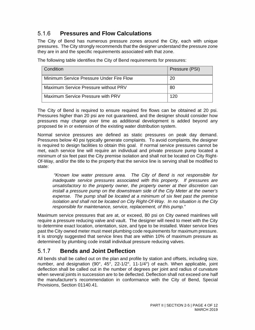
PART II | SECTION 2-5 | PAGE 4 OF 12 MARCH 2019
Pressures and Flow Calculations The City of Bend has numerous pressure zones around the City, each with unique pressures. The City strongly recommends that the designer understand the pressure zone they are in and the specific requirements associated with that zone.
The following table identifies the City of Bend requirements for pressures:
Condition Pressure (PSI)
Minimum Service Pressure Under Fire Flow 20
Maximum Service Pressure without PRV 80
Maximum Service Pressure with PRV 120
The City of Bend is required to ensure required fire flows can be obtained at 20 psi. Pressures higher than 20 psi are not guaranteed, and the designer should consider how pressures may change over time as additional development is added beyond any proposed tie in or extension of the existing water distribution system.
Normal service pressures are defined as static pressures on peak day demand. Pressures below 40 psi typically generate complaints. To avoid complaints, the designer is required to design facilities to obtain this goal. If normal service pressures cannot be met, each service line will require an individual and private pressure pump located a minimum of six feet past the City premise isolation and shall not be located on City Right-Of-Way, and/or the title to the property that the service line is serving shall be modified to state:
“Known low water pressure area. The City of Bend is not responsible for inadequate service pressures associated with this property. If pressures are unsatisfactory to the property owner, the property owner at their discretion can install a pressure pump on the downstream side of the City Meter at the owner’s expense. The pump shall be located at a minimum of six feet past the premise isolation and shall not be located on City Right-Of-Way. In no situation is the City responsible for maintenance, service, replacement, of this pump.”
Maximum service pressures that are at, or exceed, 80 psi on City owned mainlines will require a pressure reducing valve and vault. The designer will need to meet with the City to determine exact location, orientation, size, and type to be installed. Water service lines past the City owned meter must meet plumbing code requirements for maximum pressure. It is strongly suggested that service lines that are within 10% of maximum pressure as determined by plumbing code install individual pressure reducing valves.
Bends and Joint Deflection All bends shall be called out on the plan and profile by station and offsets, including size, number, and designation (90°, 45°, 22-1/2°, 11-1/4°) of each. When applicable, joint deflection shall be called out in the number of degrees per joint and radius of curvature when several joints in succession are to be deflected. Deflection shall not exceed one half the manufacturer’s recommendation in conformance with the City of Bend, Special Provisions, Section 01140.41.
PART II | SECTION 2-5 | PAGE 5 OF 12 MARCH 2019
Thrust and Restrained Joints The City requires mechanical restrained joints. Any other thrust restraints require a waiver request as specified above. All restrained systems shall be in conformance with the City of Bend, Special Provisions, Section 01140.
The Engineer shall provide calculated restrained lengths for all bends, tees and appurtenances requiring thrust restraint. Calculations shall be run under the following minimum requirements, as per AWWA standard: 2:1 safety factor, type 5 trench, 3-foot bury, 150 psi test pressure and soils consistent with the site geology (typically a GM – Silty gravel, or as determined by the engineer of record). All improvement plans shall have a restraint table stating the applicable restrain lengths for pipe size and fittings used, calculation inputs and installation notes.
Pressure Reducing Vaults Pressure Reducing Vaults designs shall be coordinated with the City on a case by case basis.
5.2 Service Lines The minimum water service line size is 1-inch diameter to the meter. This line size may be reduced through the meter as required for domestic service. The water meter shall be the same size or one size smaller than the water service line. No more than one service line per tax lot is permitted unless otherwise approved by the City Engineer.
Service lines shall be installed as shown on the Standard Drawings. All service runs shall be one continuous run of copper within the City’s right-of-way. All service lines shall have a minimum of 3 feet of cover.
Marking tape shall be installed a minimum of 12 inches above the service line at the top of the pipe zone material, centered on the service line.
Service taps at the main shall not exceed one tap every 2 feet and be a minimum 2 feet from bends or bells on the mainline. Water services are to maintain 10 feet separation from franchise utilities, sewer and storm when within the right of way or in a utility easement.
Services 2-inches and larger shall be hot tapped with a minimum 2-inch valve, using the appropriate tapping saddle and appurtenances as called out by the Engineer of Record. Service connections to existing pipe may utilize a saddle tap and valve. All water service lines shall be placed perpendicular to the water main.
New service connections greater than 2” shall be designed by a Professional Engineer.
Connections to transmission lines are not permitted. A separate distribution line shall be required to provide single services.
City standard is that services are to be provided directly to property with meters and premise isolation installed within the right of way for residential application. Reference Standard Drawings W-4, W-4A, and W-4B for residential service installation. Service connections beyond the premise isolation, installed through one property to another shall be considered private and installed within an easements. The City is not responsible for maintenance beyond the meter. Reference Standard Drawings W-5, W-5A, and W-5B for commercial service installation.

PART II | SECTION 2-5 | PAGE 6 OF 12 MARCH 2019
Water services not being used, needing to be upsized or needing to be relocated within in a parcel are required to be removed back to the main and the pipe removed from the right of way. The City requires that the corp stop shall be removed from the main and the main be plugged, unless otherwise approved by the City Engineer or designee.
If the meter assembly/box or service line is damaged during construction / site improvement activities / during the warranty period or if the existing meter box or service line does not meet current City Standards and Specification, the developer / property owner will upgrade the components of the service out of conformance.
For all non-residential potable services a minimum of a D.C.V.A. (Double Check Valve Assembly) shall be required for Premise Isolation. The Premise Isolation Assembly shall be installed in accordance with O.A.R. (Oregon Administrative Rules) 333-061-0071, Oregon Plumbing Specialty Code Chapter 6, and City of Bend Standards and Specs before a meter is set by City of Bend Utilities Personnel. The degree of hazard of each service connection shall be identified and verified by City of Bend Safe Drinking Water Program. Health Hazard connections shall be required to either utilize an approved In-Premise Backflow Prevention Assembly that is commensurate with the degree of hazard, (Air Gap or Reduced Pressure Principle Backflow Prevention Assembly) or install the Health Hazard Assembly as Premise Isolation. A Reduced Pressure Backflow Assembly will be required at the service connection when non-potable water services (i.e., COIC irrigation) and City water services exist at the same project site, per State regulations.
All residential water services shall have the backflow assembly/meter loop installed by City of Bend Utilities Personnel after construction and inspection approval of the service pipe and water meter box.
5.2.1 Services Off of Fire Lines The City of Bend will not permit fire hydrant or fire sprinkler lines to be used as the domestic service line. Potable water services must be tapped from the main separate from the fire line. Fire sprinkler services shall not connect to fire hydrant lines unless approved by the City Engineer.
Fire sprinkler lines must have a Double Check Detector Assembly (DCDA) installed with leak detection meter. The City’s ownership of the fire sprinkler lines terminate at the right of way line with the installation of a gate valve per the standard drawing W-13B. All fire sprinkler lines and fire sprinkler vaults shall be reviewed by the Building Department when on private property to be in conformance with plumbing and fire code regulations. Fire sprinkler vaults are required at the right of way when the building exceeds 20 feet from the right of way line. In the instance where the building is within 20 feet of the right of way, the developer has the option of installing a fire sprinkler vault or installing the fire sprinkler plumbing (DCDA, Post Indicator Valves, and Fire Department Connections) within the building as approved by the Building Official.
Fire sprinkler services that use any chemical additions shall require an approved R.P.D.A. (Reduced Pressure Principle Detector Assembly). Fire services, vaults and backflow prevention assemblies shall be installed in accordance with O.A.R. (Oregon Administrative Rules) 333-061-0071, Oregon Plumbing Specialty Code and City of Bend Standards and Specs.
Unless approved otherwise, fire hydrant lines on private property shall have premise isolation at the right of way. The hydrant main and hydrant is privately owned and maintained by the property owner beyond the premise isolation.

PART II | SECTION 2-5 | PAGE 7 OF 12 MARCH 2019
5.3 Valves Main line valves shall be located in the public right-of-way. The maximum distance between valves is 1,000 feet on transmission mains and 500 feet on distribution mains. Valve locations to be determined by the City. Typically, transmission mains are defined as lines that have no other services or distribution connections to them and are typically coming from one of the sources of water. All other lines are distribution lines.
5.3.1 Valve Location Valves shall be located outside the normal path of wheel travel, bike lanes, and accessible travel path. No valve shall be located within 3-feet of an existing or proposed street gutter line and shall fall minimum 12 inches beyond the gutter pan where curb and gutter exists. All valves shall have a minimum distance of 18 inches measured from the top of the valve body to the top of the road surface. Where valves fall outside paved roadways, a concrete collar shall be constructed not less than 6 inches deep and centered in a 3-foot by 3-foot pad.
At all tee and cross fittings, valves shall be installed on every branch of the fitting unless otherwise approved by the City Engineer. In cases where the legs of the branches of the fitting are of different sizes, a valve shall be placed on the smaller diameter first. All valves shall be located within 5-feet of the cross or tee fitting.
At all dead-end lines shall be terminated using a valve and blow off.
Hot taps to existing watermains shall be permitted depending on the location of existing valves in the vicinity. Where valves are not adequate to the existing system, a cut in tee will be required with valves installed on all branches, or as determined by the City Engineer. Size-on-size taps will not be permitted unless approved by the City Engineer.
5.3.2 Valve Types Gate valves are required on all waterlines 8 inches and smaller. Butterfly valves shall be used on all waterlines of 10-inch diameter or larger; or on smaller diameter lines where 18 inches of cover to the top of a gate valve body cannot be obtained. Butterfly valves shall be mounted with the stem vertical and on the “curb” side of the main.
Air-Vac/Air Release valves shall be considered during design. Typically these will be located at all elevation rises and elevation high points. Typically, a 1-inch Air-Vac valves shall be installed for 12-inch and smaller water mains and 2-inch Air-Vac/Air Release valves installed for all larger watermains, however the sizing shall be verified against manufacturer’s recommendation. All Air-Vac/Air Release valves will be located outside the vehicular roadway as illustrated in the Standard Details. All Air-Vac/Air Release valves shall be designed to be insulated to protect against a sustained temperature of -10 degrees Fahrenheit. Hydrants are not considered Air-Vac or air release.
5.3.3 Pressure Reducing Valves Projects requiring a PRV station shall set up a meeting to discuss design requirements.
5.3.4 Blow-Offs Blow off valves shall be located on all dead end lines. New lines that are connecting to existing lines at both ends will require a temporary blow-off for chlorination purposes. In no cases shall hydrant spacing be modified to use as a blow off. Design shall address

PART II | SECTION 2-5 | PAGE 8 OF 12 MARCH 2019
how water from blow off and flushing will be addressed to prevent any erosion or landscape damage.
5.4 All-Weather Access Where water facilities requiring maintenance access outside paved right-of-way, a paved access pad or road sufficient for service equipment to operate without blocking the traveled way shall be constructed. Where water facilities (such as fire hydrants and valves) are away from paved right-of-way, a 14-foot wide 2-inch thick paved all weather access road, with a 6-inch base, or as approved by the City Engineer, shall be installed to provide access. If the access road requires a vehicle turn around, adequate space shall be included for an all-weather access road.
Where water facilities not requiring maintenance access (such as transmission lines) lie away from paved right-of-way, an all-weather access road shall be constructed over the line. This all-weather access road shall be a minimum of 14-feet in width and shall be surfaced with a minimum of 6-inches of compacted aggregate base. Compaction and treatments shall be in conformance with Part II, Section 2-3. The road shall be shaped to promote drainage and shall not cause the ponding of storm runoff.
5.5 Meters All water service lines must have a meter box and assembly placed a minimum of 1 foot outside of hard surfaces (concrete and asphalt) unless approved by the City Engineer. Where meter boxes are unable to be located outside hardscape, an expansion joint shall be installed 12-inches around the entire perimeter of the meter box. When meter boxes are located in sidewalks with tree wells, the meter box shall be located a minimum of 6 feet from the tree well. Fire lines no longer require meters but are required to have double detector check assemblies (DCDA) to detect low-flow events. Any service line that is providing water from the City of Bend distribution system for purposes other than fire flow must have the entire amount of water used measured. Water meters shall be sized to the water service line size or one size smaller.
New meters installed at commercial and industrial properties must be one-inch minimum.
Commercial water meters shall be installed on residential projects that have three dwelling units or more.
Meters that are 3 inches or larger will be either a Sensus Omni or HbMag. All accessories, except the MTU, need to be included to insure the meter functions properly.
For domestic water services, the City’s ownership ends at the meter. City’s ownership for fire services ends at the right of way.
5.5.1 Automatic Meter Reading Systems The City requires the STAR Network AMI system as manufactured by Aclara on all metered services.
All meters shall include an Aclara/STAR meter transmission unit. The transmission unit shall be installed on the bottom of the meter box lid as shown in the Standard Details.

PART II | SECTION 2-5 | PAGE 9 OF 12 MARCH 2019
5.5.2 Standard Meters All water meters 2-inch and smaller shall be installed by the City of Bend. Meters shall be approved by the City prior to installation.
5.5.3 Vaults and Meter Boxes, Including Insulation All vaults and meter boxes shall be installed a minimum of 3 feet off of the corner property line in each direction. No vaults or meter boxes can be installed more than 5 feet from the property corner without approval from the City Engineer. Vaults and meter boxes are to be installed outside of hard surfaces.
Meter banks, multiple meters placed in close proximity to one another to provide multiple lot services, are permitted with approval from the City Engineer. Meter boxes shall be staggered per Standard Drawing W-4. Water taps shall be spaced a minimum of 2-feet apart at the main. Stamped or engraved stainless steel or brass address tags shall be on the meter box to identify which meter services which address. Refer to the water meter standard drawing.
The following, or an approved equal, are the only approved meter boxes for services for 2-inch and smaller. All meter boxes must be tier 8 or equal. Meter boxes shall not have mouseholes.
Brand Box Lid
Armorcast BOX –17x 30 x 18
LID-1730 Polymer with cast iron meter reader lid
Quazite Polymer concrete; flared L 17 x 30 x 18
Quazite H20 17 x 30
For all meters larger than 2-inch, the designer will determine the appropriate meter box or vault. All meter boxes and vaults must be traffic rated. See Standard Details for 3-inch and larger meters.
All meter vaults and boxes must be installed to the correct finish grade. Any that do not meet this requirement, including requirements for correct depth of meter stops and service line, will not be activated and locked off with a City of Bend lock.
5.6 Fire Services, Flows and Hydrants The City of Bend requires all new developments or extension of existing facilities to have a fire flow analysis performed. This analysis must be performed by the City of Bend. All relevant information to the proposed development or extension of services must be provided. Forms and fees for this service are available from the permit center in the Community Development Department (CDD) or on the City’s website.
The fire flow analysis uses a calibrated hydraulic model to determine available flow. The analysis uses the peak day demand in the distribution system with storage tanks at half full to determine the available flow, static pressures, and residual pressures.
No other analysis for fire flow can be substituted for the analysis performed by the City using its calibrated hydraulic model.

PART II | SECTION 2-5 | PAGE 10 OF 12 MARCH 2019
5.6.1 Fire Flow Requirements The following table is the required fire flows based on land use and development type:
Land Use Code Development Type Required Fire Flow (GPM)
AOD Airport Operations District 2,500
ARID Aviation Related Industrial District 2,500
ASD Aviation Support District 2,500
ASDRA Aviation Support District Reserve Area 2,500
CB Central Business District (CBD) 3,500
CC Convenience Commercial District 2,500
CG General Commercial District 2,500
CL Commercial Limited 2,500
CN Commercial Neighborhood 2,500
EFUTRB Exclusive Farm Use 1,500
IG General Industrial District 2,500
IL Light Industrial District 2,500
IP Industrial Park 2,500
ME Mixed Employment 2,500
MR Mixed-use Riverfront 2,500
PF Public Facilities 2,500
PO Professional Office 2,500
PO/RM/RS Mixed Use Office/Residential 2,500
RH High Density Residential 1,500
RL Low Density Residential 1,500
RM Medium Density Residential 1,500
RR10 Medium-10 Density Residential 1,500
RS Standard Density Residential 1,500
SM Surface Mining District 2,500
SR2-1/2 Suburban Low Density Residential 1,500
UAR10 Area Reserve District 1,500

PART II | SECTION 2-5 | PAGE 11 OF 12 MARCH 2019
5.6.2 Fire Service Lines The City of Bend requires all fire service lines be designed by a registered Professional Engineer up to the right of way and submitted through a right of way plan review and approval process. The fire service backflow/premise isolation device shall be designed in accordance to all applicable building/fire/plumbing codes under a building department permit. Where the building is located within 20 feet of the right of way line, the developer has the option of installing the premise isolation within the building, otherwise it shall be placed in a vault near the right of way line. All fire service lines will be installed from the nearest water main with a valve located adjacent to the tap/tee. Fire Department Connections (FDCs) and Indicator Valves (PIVs or WIVs) can be located on building walls with fire and building department approval. PIV’s and FDC’s must be located on private property, unless otherwise approved by the City Engineer. If approved by the City Engineer to be located within the right of way, the PIVs and FDCs shall be a minimum 5 feet from roadways/curb. Construction documents shall provide a plan and profile of the fire service installation up to the right of way line. The City of Bend standard detail for fire lines is a minimum standard only.
All fire service lines will require a DCDA around the backflow preventer.
Backflow Assembly vaults shall comply with the Uniform Plumbing Code requirement for electrical and heat for freeze protection as determined by the Building Department.
5.6.3 Hydrants General Each hydrant shall be connected to the main with a 6-inch-diameter ductile iron branch with a 6-inch shutoff gate valve using a restrained MJ x MJ connection. Breakaway flange shall be no higher than 4-inches above the surrounding surface for Roadside Design compliance. See Specification 01160.10(a) and Standard Drawing W-7. No valve shall be located closer than 84-inches to the hydrant. When the hydrant branch line exceeds 100 feet in length, two valves shall be required: one near the hydrant, and one at the main.
Hydrants shall comply with AWWA specification C-502-64 with a dry top, left-hand opening, and have one 5 1/4-inch steamer nozzle and two 2 1/2-inch hose nozzles. The steamer nozzle should always face the street with the exception of parking lots.
Hydrant extensions are not allowed on new hydrants but can be utilized only on existing hydrants at the discretion of the City Engineer and the City of Bend Utilities Department. Extensions shall be from the manufacturer or approved equal, with a maximum of one extension per hydrant. Hydrant extensions shall not exceed 12-inches. All hydrant extensions shall be inspected during installation and approved by a City inspector. Hydrant drains will be surrounded by a washed gravel pocket, wrapped with filter fabric or 12 millimeter plastic, to provide drainage. No hydrant drains will be connected to either the sanitary or storm sewer system.
Hydrants are not to be used in lieu if air release or air-vac valves.
5.6.4 Location Fire hydrant placement shall be outside the pedestrian path of travel. Hydrants shall be spaced at no more than 400-foot intervals. Any further spacing requires approval of the Bend Fire Department.
Hydrants shall be located such that maintenance staff has complete access. They shall also be located to minimize the possibility of damage from vehicles or injury to pedestrians,

PART II | SECTION 2-5 | PAGE 12 OF 12 MARCH 2019
with location preferred near intersections not directly on the corner. Hydrants located in parking areas must be protected, preferably by placing hydrants in a curbed landscape median/island. Concrete filled steel bollards are not preferred. Unless otherwise approved by the City Engineer, hydrants placed onsite shall have a premise isolation valve installed at the right of way line. All plumbing onsite shall be privately owned and maintained by the property owner.
A hydrant shall be positioned within 100 feet of an FDC when required by the Fire Marshall.
5.6.5 Concrete Pad Concrete hydrant pads shall be required around all hydrants (See Detail W-7 and W-8).

PART II | SECTION 2-6 | PAGE 1 OF 15 MARCH 2019
SECTION 2-6
Stormwater
Table of Contents 6.0 Stormwater .................................................................................................................. 2
6.1 Design Storm ................................................................................................... 2 6.1.1 Water Quality Design Storm ................................................................ 2 6.1.2 Water Quality Design Volume .............................................................. 2 6.1.3 Water Quality Design Flow .................................................................. 2 6.1.4 Flow Control and Conveyance ............................................................. 3
6.2 Hydrologic Basis of Design .............................................................................. 3 6.2.1 Hydrologic Design Criteria ................................................................... 3 6.2.2 Drainage facility testing ........................................................................ 4
6.3 Water Quality Treatment ................................................................................. 8 6.3.1 Treatment Controls .............................................................................. 8
6.4 Conveyance ................................................................................................... 10 6.4.1 Pipe Material ...................................................................................... 11 6.4.2 Pipe Diameter and Length ................................................................. 11 6.4.3 Placement and Alignment .................................................................. 11 6.4.4 Outfalls ............................................................................................... 11 6.4.5 Storm Drain Debris and Safety .......................................................... 11
6.5 Flow Control .................................................................................................. 11 6.5.1 Sequential Implementation ................................................................ 12 6.5.2 Fencing .............................................................................................. 12 6.5.3 Embankments .................................................................................... 12 6.5.4 Access ............................................................................................... 13
6.6 Drainage Submittals ...................................................................................... 13 6.6.1 Concept Drainage Report .................................................................. 14 6.6.2 Concept Drainage Report Applicability .............................................. 14 6.6.3 Road and Drainage Plans .................................................................. 14 6.6.4 Minimum Plan Elements .................................................................... 15

PART II | SECTION 2-6 | PAGE 2 OF 15 MARCH 2019
6.0 Stormwater To meet the City goals for stormwater management, stormwater drainage and stormwater quality as prescribed in the City of Bend Stormwater Master Plan, the City has adopted best management practices for addressing stormwater drainage in the City of Bend.
Designs of stormwater facilities and conveyance systems shall conform to the City of Bend Standards and Specifications and the applicable Oregon Department of Environmental Quality (DEQ) regulations. Where a conflict is discovered between City and DEQ requirements, the Design Engineer shall notify the City Engineer of the issue and the most stringent practice shall apply.
The City recognizes the current 2010 Central Oregon Stormwater Manual (COSM) as a standard design manual for stormwater and incorporates it into these Design Standards except as modified or otherwise prescribed herein. The following sections summarize key elements of the City design requirements. Stormwater design professionals are required to be familiar with the specific requirements and practices of the Manual and implement them fully into their designs for City approval.
6.1 Design Storm All stormwater designs for new development or redevelopment projects shall address and comply with the eight basic requirements prescribed in the COSM. Any deviation from the Basic Requirements, or other provisions of the COSM must be fully demonstrated and documented in writing by the design professional through the drainage submittal process.
6.1.1 Water Quality Design Storm The six-month National Resource Conservation Service (NRCS) Type I, 24-hour storm event is the designated water quality storm event to be utilized for both volume based and flow rate-based water quality best management practices (BMP’s).
6.1.2 Water Quality Design Volume Volume-based treatment BMPs are sized the same whether located upstream or downstream from detention facilities. The water quality design volume is defined as the volume of runoff predicted for the proposed conditions pollutant generating impervious surface (PGS) areas from the NRCS Type I, 24-hour storm with a 6-month return frequency.
6.1.3 Water Quality Design Flow For runoff treatment facilities preceding detention facilities or when detention facilities are not used, the water quality design flow is defined as the peak flow rate predicted for the proposed conditions Pollutant Generating Surfaces (PGS) areas from the NRCS Type I, 24-hour storm with a 6-month return frequency.
For runoff treatment facilities located downstream of detention facilities, the water quality design flow is defined as the full 2-year release rate of the detention facility.
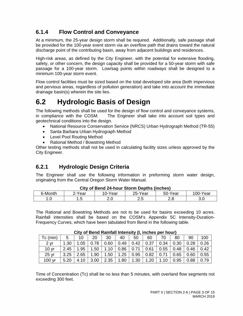
PART II | SECTION 2-6 | PAGE 3 OF 15 MARCH 2019
6.1.4 Flow Control and Conveyance At a minimum, the 25-year design storm shall be required. Additionally, safe passage shall be provided for the 100-year event storm via an overflow path that drains toward the natural discharge point of the contributing basin, away from adjacent buildings and residences.
High-risk areas, as defined by the City Engineer, with the potential for extensive flooding, safety, or other concern, the design capacity shall be provided for a 50-year storm with safe passage for a 100-year storm. Low/sag points within roadways shall be designed to a minimum 100-year storm event.
Flow control facilities must be sized based on the total developed site area (both impervious and pervious areas, regardless of pollution generation) and take into account the immediate drainage basin(s) wherein the site lies.
6.2 Hydrologic Basis of Design The following methods shall be used for the design of flow control and conveyance systems, in compliance with the COSM. The Engineer shall take into account soil types and geotechnical conditions into the design.
• National Resource Conservation Service (NRCS) Urban Hydrograph Method (TR-55) • Santa Barbara Urban Hydrograph Method • Level Pool Routing Method • Rational Method / Bowstring Method
Other testing methods shall not be used in calculating facility sizes unless approved by the City Engineer.
6.2.1 Hydrologic Design Criteria The Engineer shall use the following information in preforming storm water design, originating from the Central Oregon Storm Water Manual.
City of Bend 24-hour Storm Depths (inches) 6-Month 2-Year 10-Year 25-Year 50-Year 100-Year
1.0 1.5 2.0 2.5 2.8 3.0
The Rational and Bowstring Methods are not to be used for basins exceeding 10 acres. Rainfall intensities shall be based on the COSM’s Appendix 5C Intensity-Duration-Frequency Curves, which have been tabulated from Bend in the following table.
City of Bend Rainfall Intensity (I, inches per hour) Tc (min) 5 10 20 30 40 50 60 70 80 90 100
2 yr 1.30 1.05 0.78 0.60 0.49 0.42 0.37 0.34 0.30 0.28 0.26 10 yr 2.45 1.95 1.50 1.10 0.86 0.71 0.61 0.55 0.48 0.46 0.42 25 yr 3.25 2.65 1.90 1.50 1.25 0.95 0.82 0.71 0.65 0.60 0.55
100 yr 5.20 4.10 3.00 2.35 1.80 1.30 1.20 1.10 0.95 0.88 0.79
Time of Concentration (Tc) shall be no less than 5 minutes, with overland flow segments not exceeding 300 feet.

PART II | SECTION 2-6 | PAGE 4 OF 15 MARCH 2019
All applicable coefficients and design valves (Manning n, Time of Concentration value, etc.) are found in the COSM’s Chapter 5.
Within the public right of way, storm delineation basins shall detain storm volumes no larger than 25,000 gallons (3,342 cubic feet). Catch basins, curb cuts and all applicable storm detention infrastructure shall be designed to reduce the basin size, avoid sag low points, and connect basins with overflow piping when conditions allow.
Public street design shall incorporate the storm water catchment basin to extend a minimum of 20-feet into the private lot. If topography is such that stormwater will never enter the right of way after the private lot’s development, the Engineer of Record shall design the basin to the right of way. Calculations shall incorporate appropriate curve numbers or runoff coefficients for anticipated future impervious surface within the first 20 feet.
Where a regional storm basin (collecting private property into a public street) is to be employed in design or as determined necessary by the City Engineer, the larger basin design shall require geotechnical infiltration investigation specific for the drainage facility for use in design and have overflow structures installed to convey the 100-year storm event for the basin. The overflow is to be a separate structure from the 25-year containment facility, providing redundancy to the system.
Private sites, that meet the COSM review requirements (COSM chapter 2.1 criteria), will be reviewed by the City to ensure a 25 year 24-hour storm event is contained onsite and will not flow into the public right of way or an adjacent property. The size of private drainage facilities (UIC’s or swales) do not have a maximum size unless there is the potential of the drywell to flow into the public right of way or a neighboring private property. If said conditions exist, storm facilities shall not exceed 25,000 gallons (3,342 cubic feet) as determined by a 25 year-24-hour storm event.
6.2.2 Drainage facility testing Prior to approval of any private or public right of way project, the Engineer of Record (EOR) shall oversee the construction and testing of the drainage facilities on the approved construction documents.
Public drywell facilities shall conform to the following testing criteria:
1. Install the drywell per the approved plans, specifications and applicable construction guidelines. The EOR shall witness the construction of these facilities to ensure that the drain rock quantity is being placed, drain rock has sufficient voids, and the construction is per the City of Bend’s standards and specifications. Pictures shall be taken and provided with the EOR’s certification.
2. Inspect drywell prior to testing, making sure the drywell is clean and free of sediments.
3. Field check the accuracy of the flow meter by filling up a suitable container with known volume; for example a calibrated 55-gallon barrel.
4. Introduce clean water into the drywell and monitor using an in-line flow meter.
a. If the drywell total inflow design volume is 10,000 gallons (1,336 CF) or less, place the design volume in the drywell within a 1 hour period and verify that the water either disappears immediately or document the standing water per the COSM Appendix 4B, Full Scale Drywell Test Method.

PART II | SECTION 2-6 | PAGE 5 OF 15 MARCH 2019
b. If the drywell total inflow design volume is between 10,000-25,000 gallons (1,336-3,342 CF), place an initial 10,000 gallons (1,336 CF) into the drywell within 1 hour. If any standing water is present at the end of the 10,000-gallon test, then the City will require the full design inflow volume and/or a Full Scale 2-hour Drywell test per COSM Appendix 4B.
5. Public and private swale facilities shall conform to the following testing criteria:
a. Install the swale per the approved plans, specifications and applicable construction guidelines. The EOR shall witness the construction of these facilities to ensure the drain rock quantity is being placed per the design, has sufficient void capacity, and is constructed per the City of Bend’s standards and specifications, if applicable. Pictures shall be taken and provided with the EOR’s certification.
b. Introduce stormwater into the swale per COSM Appendix 4E (Swale Flood Test) or 4F (Pond Flood Test)
6. Infiltration testing. Post-construction infiltration testing is required. Regardless of infiltration determination/testing, it is required that the EOR certify that all stormwater infiltrate from drywells/swales within 72 hours per COSM requirements.
a. For drywells, draw down measurements shall be performance to determine infiltration rate and recorded during the drywell testing, tested in 5-minute increments for 20 minutes (obtaining 4 recorded draw down measurements). An average infiltration will be determined from the draw down measurements and compared to the design infiltration used in the calculations.
b. For swales, infiltration shall be testing in conformance to the COSM Appendix 4D (Single-Ring Infiltrometer test), or other City approved method
i. If design infiltration rates are not met during testing, the EOR shall determine how to 1) increase infiltration rates or 2) back calculate the facility design with the measured infiltration rate to determine if the facility has adequate capacity including a safety factor.
7. At the project closeout, private or public, the EOR will be required to certify the testing and construction of the drainage facilities, that they meet the performance standards under the stamped and approved design. Stormwater certification shall include
a. All testing documents
i. Recorded amount of water discharged into the facility, with start time and end time.
ii. Draw down measurements. Depth of water at end of test with depth of water at 5-foot increments for 20 minutes duration, or until the facility is dry.
iii. Construction inspection forms and pictures. Private and public project will not be approved by the City without this certification.

PART II | SECTION 2-6 | PAGE 6 OF 15 MARCH 2019
b. Certification letter. The letter shall be stamped by the project EOR on company letterhead as conforming to the approved construction document and identifying design assumptions are true in the completed facility.
Swale and drywell failure is determined if the facility cannot 1) contain volumes during the test, 2) if the facility is unable to infiltrate at the design infiltration rate (dictated in the construction documents or the storm water report) and 3) if the stormwater rises to the highest perforation in the drywell. It is the burden of the EOR to have the drainage facilities work in accordance to the design criteria approved on the construction documents.
Private and Public drainage facilities shall be tested for volume in conformance to a method determined by the EOR and in conformance to COSM and that all storm systems work in conformance to the engineer’s design.
The standard testing form to be submitted to the City is provided on the next page.

UIC/Swale (Facility) Testing Report Form
Project: Permit number:
Drywell ID: Engineer of Record:
Date Tested: Engineer Company:
Tester: Testing Company:
Facility Dimensions:
Depth (A): feet Length: feet Width: feet
Testing (Based on approved plans and COSM requirements)
Required quantity: gallons Required Testing time: min.
Assumed / Design Infiltration: gal/min = ft/min
Test Time Start:
Depth of water at start: feet
Test Time End:
Depth of water at end: feet (B)
Drawdown time – Infiltration Determination
Time (After test)
Depth, feet Depth Change, feet, (C)
Infiltration (ft./min) I = C / 5
Test End (B) = 0
5 min
10 min
15 min
20 min
Infiltration Average =
Passed: Failed:
Tester Signature: EOR signature:

PART II | SECTION 2-6 | PAGE 8 OF 15 MARCH 2019
6.3 Water Quality Treatment Water quality treatment design shall comply with Chapter 6 of the COSM with the following modifications: The City of Bend is subject to Oregon Department of Environmental Quality (DEQ) regulations for piped discharges to surface water bodies and for underground injection control (UIC) systems. All UIC systems installed shall meet rule-authorization requirements. All rule-authorized UIC systems must have a pre-treatment barrier, or other appropriate control(s) in place to treat stormwater prior to discharge into the subsurface. Additionally, UIC systems shall not be installed within 500 feet of any water wells, within drinking water protection two year time of travel areas, or in locations where the injected stormwater could affect contaminated soils or DEQ cleanup sites.
6.3.1 Treatment Controls The following treatment controls are required by the City, in descending order of preference. The treatment controls selected for a specific site shall address the pollutants expected for that site, along with the specific geotechnical conditions of the site. Projects within major drainage basins adjacent to the river or drainage basins containing MS4 system shall address pollutants of concerns for the river, which is nitrogen limited. Pollutants of concern in the river through the City of Bend related to stormwater include: sediment/turbidity, pH, dissolved oxygen, and chlorophyll a. Pretreatment for Underground Injection Controls should focus on spill control. These controls shall be designed to the guidelines included in the standard drawings, and the COSM, with the City’s standard drawings configurations and sizing taking precedence in case of a discrepancy. Treatment trains are encouraged as appropriate.
Given the importance of water quality, the City wishes to see preferred strategies in different areas of the City.

PART II | SECTION 2-6 | PAGE 9 OF 15 MARCH 2019
Table 6-1. Preferred Stormwater Strategies by Area Area Strategy Types of Controls Areas that drain to surface water
• Reduce flows to river/surface waters
• Provide highest level treatment for remaining
• Minimize sediment • Prevent facility
clogging
• Drywells or infiltration trench with spill protection
• Bioretention/Infiltration swale, pond, basin, planter box
Wellhead Protection Areas (One through 10 year Time of Travel)
• Spill Protection
• Surface Infiltration Controls
• Direct runoff to outside area if can for UIC use
• Prevent facility clogging
• Water Quality Sediment Manholes, Oil/water separator TAPE approved manufactured spill control
• Bioretention/ infiltration swale, pond, basin with treatment vegetation, planter boxes
Other Areas • Dispersed System
• UICs and regional controls
• Prevent facility clogging
• Drywell or infiltration trench with spill protection (e.g., Water Quality Sediment Manholes)
• Bioretention/infiltration, swale, pond, or basin
• Planter boxes • Vegetated filter strip • Grassy swale
The City of Bend requires the installation of Sedimentation manholes, per City of Bend standard drawing STRM-7, to be constructed prior to UIC’s discharge unless otherwise approved by the City Engineer. Direct discharge from a swale into a drywell shall not be permitted without the installation of a sedimentation manhole upstream. Sedimentation manholes provide for a convenient method to trap contaminated spills and to manage sediment loads prior to injection into the UIC.

PART II | SECTION 2-6 | PAGE 10 OF 15 MARCH 2019
Table 6-2. Preferred Treatment Controls
Treatment Type UIC Pretreatment
Basic Treatment (TSS)
Oil Control (TPH)
Metals Treatment
Nitrogen3
Bioretention Systems—Storm Water Planters
X X X X X
Vegetated Infiltration Swales
X X X X X
Bioretention Systems—Landscape Detention
X X X X X
Extended Detention Dry Ponds
X X X X X
Grassy Swales X X X
Vegetated Filter Strips X X X1 X1
Sedimentation Manholes X X X X
1. Vegetated filter strips are only applicable for oil control and metals when installed in series with an above ground flow control facility, such as a detention or evaporation pond. Such designs will be evaluated on a case by case basis.
2. Treatment controls for Nitrogen were determined using the International Stormwater BMP Database, 2014 BMP Performance Summaries.
6.4 Conveyance A conveyance system includes all natural or constructed components of a storm drain system that collects stormwater runoff and conveys it in a manner that adequately drains areas, sites, structures, and roadways, minimizing the potential for flooding and erosion.
The City defines an underground injection control, UIC, system as a drywell. The Department of Environmental Quality (DEQ) defines a UIC as structures that are deeper than wide at the land surface and utilize infiltration by a perforated pipe or drain field. UIC regulations do not apply to swales, french drains, or footing drains. UICs are to be placed outside the groundwater 2-year time of travel zones for drinking water source areas and not within 500 feet from a water well. Refer to DEQ UIC registration and rule authorization guidelines.
Drillholes are no longer permitted within the City of Bend right of way. Projects that contribute to or front an existing drillhole will either be decommissioned in accordance to DEQ requirements or have upstream infrastructure (sedimentation manholes and/or City of Bend catch basins with sumps, as approved by the City Engineer) constructed. Conveyance systems in the City of Bend shall be designed in accordance with COSM.

PART II | SECTION 2-6 | PAGE 11 OF 15 MARCH 2019
6.4.1 Pipe Material Storm pipe under roadways or in areas that have traffic loads shall be constructed of AWWA C900 PVC pipe. Where storm pipe is within the landscape strips beyond the street curb, the Engineer has the option of using ASTM D3034 PVC sewer pipe. All pipe installed shall conform to City of Bend specifications.
6.4.2 Pipe Diameter and Length The minimum pipe diameter shall be 8 inches. Pipe diameter shall be determined to ensure it is of proper size to convey a minimum 50-year storm event. When in the sag/low point, the pipe shall be sized to a 100-year storm event. The maximum length of pipe between junctions shall be no greater than 300 feet. Pipe diameters cannot be downsized for downstream runs.
6.4.3 Placement and Alignment No storm drain pipe in a drainage easement shall have its centerline closer than 5 feet to a private rear or side property line or 10 feet from building foundations or other structures. For a storm drain located under the road, the storm drain shall be placed in accordance with the City of Bend standard detail. If it is anticipated that a storm drain system may be expanded in the future, provisions for the expansion shall be incorporated into the current design. Minimum depth of pipe is 12 inches below street base to top of pipe.
Drywell perforations shall be constructed in native soils, outside fill material. The drywell barrel foundation shall always be constructed on native ground.
Storm pipes shall meet the separation requirements of a sewer pipe: 10 feet from water mains and services. Storm pipe vertical separation from water mains/services shall be 18 inches unless a storm pipe is installed as AWWA C-900 PVC with a full stick of pipe centered at the water crossing.
6.4.4 Outfalls New outfalls to the Deschutes River or other water bodies designated as waters of the United States require regulatory agency approval.
6.4.5 Storm Drain Debris and Safety Debris protection shall be provided for storm drain systems. Debris may consist of soil deposits (that is, silt, sand, gravel and boulders), limbs, sticks, trash, or other landscaping materials.
Safety bars shall be provided for outfalls with a diameter of 18 inches or greater to protect from unauthorized individuals entering the storm drain system. Outfalls within a fenced area are not required to have safety bars. The clear space between bars shall be less than 4 inches.
6.5 Flow Control Flow control facilities mitigate potential adverse impacts on downstream properties and natural resources resulting from the increase in stormwater runoff caused by land development.

PART II | SECTION 2-6 | PAGE 12 OF 15 MARCH 2019
Unless specifically approved by the City of Bend, stormwater runoff from any proposed land development to any natural or constructed point of discharge downstream shall not exceed the pre-development peak rate of runoff.
Flow control systems in the City of Bend shall be designed in accordance with COSM.
6.5.1 Sequential Implementation In general, for any activity that creates, alters, or modifies a natural or man-made drainage system the following control measures are to be implemented sequentially:
1. Reduce runoff volumes and polluted runoff through Low Impact Development designs and source control measures.
2. Address stormwater drainage with surface systems, such as above ground vegetated infiltration swales.
3. If surface control does not provide adequate capacity, treat the water quality storm in a surface facility and provide an overflow to an approved regional above ground retention facility or rule authorized UIC.
6.5.2 Fencing Fencing or other barriers shall be required to protect the health, welfare, and safety of the public under the following circumstances:
• Ponds with the first overflow at 3 or more feet above the pond bottom
• Ponds with side slopes in excess of 3H:1V
• Drainage facilities with retaining walls 2.5 feet high or taller The City of Bend reserves the right to require a fence around any drainage facility should there be a concern for safety.
The minimum fencing requirements are as follows:
• The fencing shall be at least 4 feet tall unless otherwise specified by the City of Bend, and provide visual access per the City of Bend building code requirements for fence height and openings.
• Gates are to be provided where drainage facilities are fenced. The gates shall be a minimum of 12 feet wide with provisions for locks. Separate gates may need to be installed where the maintenance access drive connects to a public or private roadway.
• At the discretion of the City of Bend, marking fences (that is, vegetation, boulders, etc.), terraces, steeper side-slopes, egress bars, etc., may be allowed.
6.5.3 Embankments The height of an embankment is measured from the top of the bank to the catch point of the native soil at the lowest elevation. Embankments shall meet the following minimum requirements:

PART II | SECTION 2-6 | PAGE 13 OF 15 MARCH 2019
• Embankments, 4 feet in height or more, shall be constructed as directed by a Licensed Geotechnical Engineer.
• Embankments shall be constructed on native consolidated soil, free of loose surface soil materials, roots, and other organic debris.
• The embankment compaction to 95 percent of the Modified Proctor Density, ASTM Procedure D698. Placement moisture content should lie within 1 percent dry to 3 percent wet of the optimum moisture content.
6.5.4 Access Maintenance access roads shall be provided to control structures and other drainage structures associated with the stormwater facility (that is, inlet or bypass structures). Where storm infrastructure is away from paved right-of-way, a 14-foot wide 2” thick paved all weather access road, with a 6-inch base, or as approved by the City Engineer, shall be installed centered over the sewer line with 6’ x 6’ asphalt or concrete pad around manholes.
In ponds and swales, an access ramp is required.
6.6 Drainage Submittals This section provides a framework for uniformity in Drainage Submittal preparation. Properly drafted construction plans and supporting documents should also facilitate the operation and maintenance of the proposed drainage system long after design and construction. The City of Bend reviews the Drainage Submittal for compliance with these Design Standards and other applicable standards. The Drainage Submittal includes the Construction Plans, Full Drainage Report, and, other documentation to support the proposed stormwater management methods for the project. Depending on the complexity of the project, the City of Bend may request that a Concept Drainage Report (CDR) be submitted for review with the planning application or during the preliminary design process. The submittal and/or approval of the CDR does not replace the Drainage Submittal requirements. State law requires that all engineering work be performed by, or under the direction of, a qualified Engineer. The final Drainage report will be signed and stamped by a registered Engineer. The Drainage submittal shall include the following components:
• Narrative o Project Description o Summary of Basin Requirements and other conditions/permits o Summary of Geotechnical Site Characterization o Downstream/Down-gradient Analysis o Hydrology Assumptions o Storm water Facility Description, existing and proposed o Conveyance System Description o Erosion and Sediment Control (ESC) Measures Description

PART II | SECTION 2-6 | PAGE 14 OF 15 MARCH 2019
o Long Term Maintenance Inspection plan / agreement – Provide calendar of required
inspections Spill Prevention and Control Plan ESC Plan
• Storm Basin Map
• Soils Map
• Phasing Map (if applicable)
• Site Photos
• Hydrology Calculations
• Facility Sizing Calculations
• Conveyance Calculations
• UIC / swale testing criteria
• UIC rule authorization / registration documents, if available at time of report submittal
• 1200C permit plans and application, if applicable
• Grading, drainage facility, and erosion control plans (11x17). The Long Term Maintenance section of the report shall be on a separate page as it will be attached to a Storm Water Maintenance Agreement (SWMA), if applicable for the site work. Storm Water Agreements are not required for public facilities Drainage submittal requirements in the City of Bend shall be in accordance with COSM with the following modifications.
6.6.1 Concept Drainage Report Acceptance of a CDR does not relieve the project proponent from a Geotechnical Site Condition Report, a Downstream/Down-Gradient Analysis, or changes to the design that may be necessary in order to meet the criteria and standards found in these Standards and the City of Bend’s guidelines.
6.6.2 Concept Drainage Report Applicability The City of Bend also reserves the right to require a CDR for projects when any unspecified drainage conditions or extenuating circumstances are present.
6.6.3 Road and Drainage Plans Construction drawings shall be submitted for review by the City of Bend. The submittal and acceptance process shall be in accordance with the current City of Bend Standards and Specifications. Road and drainage plans shall include the City of Bend standard notes for construction.

PART II | SECTION 2-6 | PAGE 15 OF 15 MARCH 2019
6.6.4 Minimum Plan Elements The road and drainage plans shall provide enough detail for a third party to be able to construct the proposed facilities per the Engineer’s design. At a minimum, the plans shall meet the City of Bend’s Design Standards, and the minimum plan elements described in the COSM.

PART II | SECTION 2-7 | PAGE 1 OF 5 MARCH 2019
SECTION 2-7
Grading and Erosion Control
Table of Contents 7. Grading and Erosion Control ..................................................................................................... 2
7.1 Erosion Control .................................................................................................................... 2
7.1.1 Erosion Control Plans ................................................................................................. 2
7.1.2 Erosion Control Maintenance ..................................................................................... 3
7.1.3 Erosion Control Slope Mitigation ............................................................................... 4
PART II | SECTION 2-7 | PAGE 2 OF 5 MARCH 2019
7. Grading and Erosion ControlA comprehensive grading and clearing plan is required by the City of Bend Grading/Excavation/Stormwater Management Ordinance (Title XVI). Soil conditions shall be addressed with the information gathered from the requirements of Section 2-11 where slopes greater than 2 horizontal to 1 vertical (2:1) exist, retaining walls greater than 48” in height or extensive areas of fill are proposed, unusual soil conditions are encountered or upon the request of the City Engineer. Retaining walls or any other special structures shall be shown on the plans. Walls within 2 feet of a property line, having hydrologic, vehicular, or structural surcharge, or exceed 48 inches in height shall be designed by a registered Engineer and reviewed by the City of Bend for permitting. If a rockery/boulder wall is proposed for a site, a prescriptive design and installation document is available on the City of Bend’s Community Development Department’s (CDD) website providing additional permitting information. If grading permit is required per Title XVI no work shall commence until a grading permit has been issued and a preconstruction meeting has been held. All grading, erosion and drainage control plans submitted for review shall include the components required under the Central Oregon Stormwater Manual (COSM) and Title XVI of the Bend Development Code (BDC). Grading shall never exceed a 2:1 cut/fill unless slope is verified by a geotechnical engineer and stabilized promptly after grading. 1.5:1 cuts are permitted where excavation is within stable rock. If a site exceeds 2 feet of fill, structural backfill shall be placed and tested in conformance to a geotechnical engineer’s specifications. The City of Bend Building Department will require testing of this fill structure backfill before placement of structures on it.
7.1 Erosion Control Erosion control methods shall be shown on all construction documents and grading plan submittals. Every plan shall include methods for 1) temporary erosion control methods, 2) a plan for final slope stabilization and mitigation for the disturbed ground, and 3) erosion control maintenance. Stormwater and sediments will be contained onsite, preventing the passage into right of way and/or adjacent private property. All erosion control must be installed before mobilization, grubbing and/or grading begins. Water trucks or other means of controlling dust must be present on site and/or have a tackifier applied to disturbed soils.
7.1.1 Erosion Control Plans The minimum requirements, if applicable, for an erosion control plan are as follows:
• Existing and proposed topographic contours shall be shown with adequate spacingof contour labels to easily discern direction of slope on a site.
• Clearing limits are defined. This includes site perimeter and areas to be protected(tree, utility, Areas of Special Interest, etc.)

PART II | SECTION 2-7 | PAGE 3 OF 5 MARCH 2019
• Construction Access Route. Every location where vehicles enter a site must havea construction entrance conforming to the minimum City standards.
• Sediment Controls (dust and water borne sediments)
• Soil stabilization
• Inlet Protection
• Runoff Control
• Concrete Washout
• Material Storage / Stockpiles
• Channel and outlet stabilization
• Dewatering
• Permanent Facilities
• Drywells, swales, other permanent detention/retention facilities
• Permanent erosion control for un-vegetated soils and slopes.Inlet protection placed on grated inlets of street surfaces (bio-bags, gravel bags, bales, etc.) will not be permitted. All grated inlets are required to have Pre-Fabricated Filter Inserts with overflow installed per COB standard drawing E-2B. Field fabricated inserts (filter fabric, drain cloth, etc.) are not permitted. Street surface inlet protection (bio-bags, gravel bags, bales, etc.) will only be permitted for Ditch Inlets and Curb Cut Inlets per COB standard drawing E-2A.
7.1.2 Erosion Control Maintenance Erosion control shall be maintained on all projects by the contractor under the guidance of the project EOR. The minimum maintenance of the Best Management Practices (BMPs) are as follows:
• Inspect on a regular basis (at a minimum weekly, and daily during/after a runoffproducing storm event). All erosion and sediment control BMPs are to be fixed,replaced, or additional BMPs added immediately upon finding they are out ofconformance or not functioning.
• Maintenance and repair:
o Sediment must be removed from behind a Sediment Fence when it hasreached a height of 1/3 of the fence height and also before fence removal.
o Sediment must be removed from behind Bio Bags, Straw Wattles, andother barriers when it has reached a height of 2 inches and also beforeBMP removal
o Sediment must be removed from a sediment basin or catch basin when ithas filled half (50%) of the facility storage capacity (sump area) and also atthe completion of the project.
• Remove temporary ESC BMPs within 30 days after the temporary BMPs are nolonger needed.

PART II | SECTION 2-7 | PAGE 4 OF 5 MARCH 2019
• Permanently stabilize areas that are disturbed within 10 days of the projectcompletion or when no work is being conducted.
• When soils are tracked onto pavements, said pavements shall be immediately beswept and kept clean
• Contractors are expected to track weather conditions and forecasts and stabilizesites as needed to prevent erosion.
7.1.3 Erosion Control Slope Mitigation Prior to a site’s approval, all disturbed, steep slopes (exceeding 2 horizontal to 1 vertical -2:1), must be treated for long-term erosion control. Disturbed ground of lesser slopes shall treated for erosion control if erosion would transport sediments into either the right of way or a neighboring property.
Disturbed ground, especially steep slopes, shall be seeded. Seeding requirements are as follows:
• Seed shall be applied in as a hydroseeding application, containing tackifier andfertilizers.
o Seed mix shall be free of noxious weed species, be native drought tolerant,and self-perpetuating. The following is seed mix, or approved equal, shallbe used
Seed mix A Lolium perenne ssp. Multiflorium Italian (Annual) Ryegrass Festuca rubra var. sealink Sealink Slender Creeping Red Fescue Festuca breviplia var. Spartan II Spartan II Hard Fescue Triflorium repens White Clover Puccinellia pumila var Fults Fults Dwarf Alkaligrass
Seed mix B Elymus trachycaulus Slender Wheatgrass Lolium perenne Perennial Ryegrass Dactylis glomerata Orchardgrass Festuca rubra Creeping Red Fescue Festuca rubra Sheep Fescue Trifolium repens White Clover
o Seed shall be placed at a rate to provide 80-90% coverage over thedisturbed surface.
o For immediate germination, application shall occur when the ground is notfrozen, preferably when temperatures are between 75 and 85 degrees fromdaytime high. Hydroseeding should not occur on snow unless approved bythe City Engineer.
o Hydroseed shall be a Bonded Fiber Matrices (BFM) containing tackifier withseed and fertilizer. Install to manufacturer’s specifications or to a minimum2,000 pounds per acre on slopes flatter than 2:1, 3,000 pounds per acre on2:1 slopes or steeper, whichever is most stringent.

PART II | SECTION 2-7 | PAGE 5 OF 5 MARCH 2019
• Prior to hydroseed placement, the contractor must
o Track walk the full extent of the slope.
o Install erosion control matting/blankets, fiber rolls/waddles, or other erosioncontrol method per manufacturer’s recommendations. The contractorand/or engineer shall determine the placement of these methods are basedon the size of the disturbed slope and identification of any point discharge(channelized flows) onto the slope.

SECTION 2-8
Franchise Utilities
Table of Contents 8. Franchise Utilities ........................................................................................................................ 2
8.1 Franchise Utilities in Public Rights-of-way ............................................................. 2 8.1.1 General .......................................................................................................................... 2
8.2 New Construction and Conduit Banks ................................................................... 2 8.3 Shared Trenches ................................................................................................... 2 8.4 Trenching and Patching in Paved Right-of-way Areas .......................................... 3 8.5 Small Wireless Facilities ........................................................................................ 3
8.5.1 Deviation from Small Wireless Facility Standards .................................................. 3
8.5.2 Co-Location .................................................................................................................. 4
8.5.3 Location Guidelines ..................................................................................................... 4
8.5.4 Franchise Fees, License Fees and Permit Fees .................................................... 5

PART II | SECTION 2-8 | PAGE 2 OF 5 MARCH 2019
8. Franchise Utilities
8.1 Franchise Utilities in Public Rights-of-way 8.1.1 General Utility companies that have a current franchise agreement with the City may construct facilities in City of Bend public rights-of-way or publicly controlled easements in strict conformance with the City of Bend Standards and Specifications and the requirements stipulated in the Franchise Agreement. Prior to starting any construction, franchise utility companies shall obtain a City Excavation / Right-of-Way permit in an existing roadway or easement. Utility companies and their designers and agents shall cooperate with the City of Bend to allow for City inspection of utilities and the street restoration during construction. The intent of this requirement is to protect the interests of all utilities within City of Bend rights of way. The City of Bend prefers that franchise utilities including, but not limited to, those required for electric, communication, lighting and cable television services and related facilities be installed underground, where possible. The developer shall make all necessary arrangements with the serving utility to provide the underground services. All above-ground equipment shall not obstruct clear vision areas and safe intersection sight distance for vehicular traffic.
8.2 New Construction and Conduit Banks When a private, underground utility is not completely installed by the time of road subgrade construction, appropriate utilities conduits (dry line) shall be placed in all areas to be paved to allow future completion of the utility. Conduit termini shall extend beyond the edge of pavement or curb a minimum of 5-feet. For wired utilities (cable, phone, electric, etc.), the ends of the conduit shall be sealed and marked in accordance with the requirements of the affected utility.
Private water utilities shall construct a dry line in an area to be improved with the line extending beyond the edge of pavement or curb a minimum of 5-feet. Any valves or thrust restraint for design conditions shall also be installed at the time the dry line is constructed.
All installations of private utilities shall be subject to the inspection of the affected utility and shall be acceptable to both the affected utility and the City of Bend.
8.3 Shared Trenches Private underground utilities shall not be located within 10-feet horizontally of any water or sewer main line and shall be separated a minimum of 1-foot vertically. This requirement does not strictly apply to sewer service lines extending to individual properties. All private utility crossings of public water or sewer mains shall be perpendicular to the roadway travel path.

PART II | SECTION 2-8 | PAGE 3 OF 5 MARCH 2019
Utilities may share the sewer service trench in right-of-way areas in accordance with franchise utility agreements for shared trenches.
8.4 Trenching and Patching in Paved Right-of-way Areas
Trench excavation and backfill shall conform to City Standard drawings R-10, R-11 and ODOT specification section 00405. Trench patching shall conform to City Standard drawing R-10 and ODOT Specification.
Trenching for underground utilities shall be per City of Bend Standard Drawings R-10 and R-11 and specification section 00405.
8.5 Small Wireless Facilities Small Wireless Facility installations shall conform to the City of Bend Standards and Specifications, as well as the current version of additional references as specified and/or amended in the various subsections below. Small Wireless Facilities additional references include, but are not limited to:
• City of Bend Development Code and Ordinances of the City of Bend;
• ORS 757.270 to 757.290;
• Oregon Joint Use;
• OPUC regulations;
• NESC;
• Applicable Building Codes;
• Adopted joint use and co-locating requirements of all approvedfranchisees within the City of Bend; and,
• All other referenced documents cited herein.
8.5.1 Deviation from Small Wireless Facility Standards The City of Bend provides for Small Wireless Facility installation designs that are flexible and reflective of their context while meeting current safety and operational standards. There may be times when compliance with the City of Bend Standards and Specifications is not desired or possible and the City’s design standard deviation process shall be followed to receive approval from the City Engineer. The City Engineer may delegate review authority.
This standard deviation process shall not be used to override a requirement of a land use decision once finalized. The Bend Development Code has provisions for requesting modification to land use requirements. Except as provided elsewhere, in other City codes, resolutions, and land use actions; written requests for deviations from these Small Wireless Facilities design standards shall be reviewed and may be granted by the City Engineer according to the criteria outlined in Part I Section 2 of this document.

PART II | SECTION 2-8 | PAGE 4 OF 5 MARCH 2019
8.5.2 Co-Location The City of Bend prefers all Small Wireless Facilities be co-located per BDC Title 3.7. If the facilities cannot be co-located and a Franchisee wishes to install its facilities in the ROW, the Franchisee shall use the City and County of Denver – Small Cell Infrastructure Guidelines (April 2018) Chapters 1, Chapter 4, Chapter 5, Appendix A and Appendix B. All attachments to existing or new utility poles will be permitted through the approved Joint Use process of the utility pole owner. Attachments to City owned street luminaires shall comply with Chapter 3. Attachment to City of Bend Traffic Signal arms and structures is prohibited unless otherwise approved by the City Engineer and ODOT.
All references in the City and County of Denver – Small Cell Infrastructure Design Guidelines to “Xcel Energy” will mean the applicable utility pole owner, i.e. Pacific Corp or Central Electric COOP or other owner. All references to “City” and “County of Denver” will mean the “City of Bend.” All inconsistencies, conflicting standards, and final interpretations of this or any additional references is at the discretion/ professional judgement of the City Engineer.
8.5.3 Location Guidelines The following are guidelines for siting individual Small Wireless Facilities.
• Every effort should be made to install equipment in vaults underground or concealed as provided by the referenced design guidelines above.
• Power connections to free standing facilities shall be buried underground in vaults unless otherwise approved.
• All supporting equipment and connections to telecom facilities shall be installed in vaults underground, unless adequately shielded per the design guidelines or as approved otherwise.
• New facilities linked together via fiber optics or other telecommunications infrastructure (other than wireless) will need to be designed as an Infrastructure/Tier Three ROW permit and shall be installed underground (connecting cables and power) unless they are co-located on existing power and telecom facilities.
• Free standing facilities shall comply with Type 4 design specifications in Chapter 4 of the above referenced guidelines and shall be installed in all residential and business corridors as identified by the City during permitting.
• An applicant wishing to attach to existing City of Bend facilities i.e., street luminaires, shall demonstrate that the pole(s) are appropriately sized, and have significant strength to support the additional equipment. Applicant shall provide an engineering analysis of the structure by an engineer professionally registered in the State of Oregon.
• Refer to sections 3.4, 4.5, and 5.5 of the City and County of Denver – Small Cell Infrastructure Guidelines (April 2018) for additional placement requirements as applicable.

PART II | SECTION 2-8 | PAGE 5 OF 5 MARCH 2019
• The City will review ROW permits concurrently with Joint Use applications for co-location requests with the applicable utility. Approval of all permits is conditional on approval of the Joint Use application from the franchise utility.
• See Standard Drawing R-2 for clear vision requirements.
• The location of all co-located facilities shall be provided to the City in the form of an as-built drawing per Part II – Chapter 2.6 of these standards. All installations in the City’s ROW shall be permitted per section 3.40 of the Bend Code.
8.5.4 Franchise Fees, License Fees and Permit Fees Small Wireless Franchise Utilities shall pay all applicable franchise fees, license fees and permit fees in an amount established by the Fee Resolution or applicable Franchise Ordinance or Franchise Agreement, subject to any limit imposed by federal law. Utilities that do not have franchises shall pay the Utility License Fee plus applicable permit fees as outlined in the City’s Fee Resolution, subject to any limit imposed by federal law.

PART II | SECTION 2-9 | PAGE 1 OF 2 MARCH 2019
SECTION 2-9
Canal and Irrigation Laterals
Table of Contents 9.1 General ............................................................................................................... 2 9.2 Design ................................................................................................................. 2 9.3 Materials ............................................................................................................. 2 9.4 Testing ................................................................................................................ 2 9.5 Easements .......................................................................................................... 2

PART II | SECTION 2-9 | PAGE 2 OF 2 MARCH 2019
9.0 Canal and Irrigation Laterals
This chapter applies to all Private Irrigation District Canal standards and lateral piping considerations, but is primarily intended to cover open channel and piped conveyance of Irrigation District water through and across public rights of way.
9.1 General All new or replaced Irrigation District canals and laterals shall be installed in culverts to outside the limits of public and utilities infrastructure in rights-of-way. The construction and design shall conform to the requirements of the Irrigation District and the City of Bend. Where requirements may conflict or differ, the requirement providing the highest level of control, security, and/or integrity shall govern the construction.
9.2 Design The design sizing requirements of Irrigation District canals and laterals shall be determined by the appropriate irrigation company or their agents.
9.3 Materials The conduit used for Irrigation District culverts in the City right-of-way shall conform to the requirements of stormwater Chapter 8 of design standard in this manual. Where less than 36 inches of cover is provided, but not less than 18 inches, AWWA C-900 or C-905 pipe shall be used.
N-12 high density polyethylene corrugated Water Tite (WT) pipe to meet or exceedASTM 3212, ASTM C969 may be used only at the direction of the City Engineer andwhere the piping requirements necessitate arch culvert pipe. Piping shall be traffic-ratedand shall be the heaviest gauge produced for the size specified. No joints shall beallowed under the pavement section of a city street unless noted on the plan and with anappropriate joint seal, and approved by the City Engineer.
9.4 Testing Prior to testing any Irrigation District Standards, all other underground utilities shall be complete and in place. Pressure testing shall be performed for all irrigation pipe installations as specified in Part II Section 2.6 and Bend Standard Specifications as applicable to gravity or pressurized pipe systems.
9.5 Easements Required easements shall be clearly depicted on plans and include a label and an easement statement. Easement widths shall be shown on the construction plans and plats. The full length of the easement shall be depicted where applicable. The smallest width for an irrigation lateral easement shall be 10-feet and requires City of Bend approval

SECTION 2-10
Surveying
Contents 10. Surveying .............................................................................................................. 2
10.1 Datum Requirements ................................................................................. 2 10.1.1 Horizontal Datum ........................................................................ 2 10.1.2 Vertical Datum ............................................................................ 2
10.2 Aerial Photography and Photogrammetry ................................................. 2 10.2.1 Photo Targets ............................................................................. 2 10.2.2 Supplemental Ground Surveying ................................................ 2 10.2.3 Confidence Points ....................................................................... 2
10.3 Requirements for a Licensed Surveyor ..................................................... 3 10.4 Use of Benchmarks ................................................................................... 3 10.5 Survey Data Required on Plans ................................................................ 3 10.6 Construction Phase Surveying .................................................................. 4
10.6.1 Supplemental Control ................................................................. 4 10.6.2 Construction Staking ................................................................... 4 10.6.3 Cutsheets .................................................................................... 5
10.7 Final Submittal of Electronic Files ............................................................. 5 10.7.1 CAD Files .................................................................................... 5 10.7.2 Word Processing Documents ..................................................... 5 10.7.3 Image Files ................................................................................. 5

PART II | SECTION 2-10 | PAGE 2 OF 5 MARCH 2019
10. Surveying
10.1 Datum Requirements 10.1.1 Horizontal Datum Horizontal datum shall be based on the Deschutes County Coordinate System. The DCCS is a commonly used coordinate system, well-monumented within the City and available to all designers. It is also referred to as the “Central Oregon Coordinate System” and the “Deschutes County Grid”. In any case, the basis for the coordinates is common to each. When converting to a Local Datum Plane (LDP), in which distances represent true ground distances, the project combined scale factor shall be stated for converting distances and coordinates between ground and grid. The combined scale factor shall be the product of the project elevation factor and the project grid factor.
10.1.2 Vertical Datum Vertical Datum shall be NGVD 29.
10.2 Aerial Photography and Photogrammetry Accuracy – Photo mapping for the purpose of creating a detail (base) map and Digital Terrain Model (DTM) shall be conducted so as to achieve at least 0.10-foot accuracy on hard surfaces.
10.2.1 Photo Targets Aerial photo targets set within the project limits shall be surveyed for elevation by one or more closed differential or trigonometric level loops. The error of closure of each loop shall not exceed 0.02 foot. The elevations of aerial targets lying outside the project limits may be determined by GPS or other methods.
10.2.2 Supplemental Ground Surveying Areas obscured or otherwise not detected by aerial photography shall be surveyed using ground methods that achieve at least 0.10-foot accuracy on hard surfaces.
10.2.3 Confidence Points Random confidence points shall be measured in the field to verify the accuracy of the DTM. Confidence points shall NOT be included in DTM computation. There are four types of confidence points:
• Surfaced – hard surfaces (asphaltic concrete or concrete pavement, bridge decks,and walks)
• Graded – graded and possible compacted surfaces but not intended to be thetraveled way

PART II | SECTION 2-10 | PAGE 3 OF 5 MARCH 2019
• Natural – surfaces in their natural state
• Rugged – extremely irregular surfaces (large rock outcroppings, rocky riverbottoms, etc.)
The minimum number of confidence points required is 10 per instrument setup or 2 percent of the total number of contourable points used for the DTM. Two-thirds of all errors must fall within the error tolerances and 100 percent of all errors must fall within three times the error tolerances according to Table 12-1.
TABLE 12-1 Error Tolerances Type Imperial (feet) Metric (millimeters)
Surfaced +/- 0.1 +/- 30
Graded +/- 0.3 +/- 100
Natural +/- 0.6 +/- 200
Rugged +/- 1.5 +/- 500
Confidence points shall represent all surface types contained in the DTM, shall be proportional to the four surface types depicted in the DTM, shall provide a good sampling of the overall model, and shall be placed randomly.
10.3 Requirements for a Licensed Surveyor All tasks requiring boundary, right-of-way, and easement determination, design mapping, horizontal and vertical control, legal description writing, construction staking, and any other surveying services necessary to prepare construction plans shall be performed under the direct supervision of an Oregon Registered Professional Surveyor.
10.4 Use of Benchmarks Where practical, two or more benchmarks shall be surveyed and the elevation differences compared with the published data. If an unacceptable discrepancy between two or more benchmarks is discovered, measures shall be taken to determine which elevation(s) is wrong, and the bad elevations shall be corrected and brought to the attention of the proper jurisdiction.
10.5 Survey Data Required on Plans In addition to the requirements of Section 2-2.3.1, Information Required on Plans, General, the following survey data shall be shown.
Project control points shall be shown graphically on the corresponding plan sheets. Tables listing Point Number, Northing, Easting, Elevation, and Point Description shall be shown on all plan sheets on which control points appear. A statement describing the project Basis of Bearings and the horizontal datum shall be placed on the Horizontal Control Sheet.

PART II | SECTION 2-10 | PAGE 4 OF 5 MARCH 2019
The benchmark used for project vertical control shall be described on the Horizontal Control Sheet. The description shall include the location, type, size, and origin of monument, if known, and the elevation and vertical datum.
10.6 Construction Phase Surveying 10.6.1 Supplemental Control Any additional survey control point(s) needed for construction staking shall be established by one of three methods:
• The point(s) shall be double-tied from existing adjusted control by measuring froma minimum of two different existing control points and averaging the xyzcoordinates, or the point(s) shall be measured twice from an existing control pointusing a different existing, adjusted backsight point for each measurement, andaveraging the xyz coordinates.
• The point(s) shall be included in a closed, adjusted traverse that begins and closeson two existing adjusted control points.
• The point(s) shall be included in a network survey that is adjusted by the Methodof Least Squares.
10.6.2 Construction Staking Construction staking shall include staking of 2 reference points (swingtie information) to allow horizontal and vertical location of hydrants, sewer services, and water services. These stakes shall be provided prior to construction of facilities so that City inspectors may verify position of facilities. Stakes shall be maintained for a minimum of 5 working days
• Fire hydrants shall be referenced with two offset stakes with data showinghorizontal distance to face of hydrant, face of curb, and elevation of top of curb,and where practical, both stakes shall be placed at different distances on theextension of water line to the hydrant. Curb, if designed, shall be staked at thehydrant location approximately 5 feet ahead and back of the hydrant’s centerlinestation.
• Sanitary and storm manholes and catch basins shall be referenced with two offsetstakes with data showing horizontal distance to service at property line, and invertelevation of the connection at property line or easement line. All utility servicelaterals to existing or proposed lots shall be staked at the lot line abutting the street.The cut/fill to the rim and to all designed invert elevations of a structure shall benoted on the construction stakes.
• Curb shall be staked at station intervals acceptable to the construction contractor,but at minimum, at all horizontal and vertical event points and at 25 foot intervalson curb lines. Horizontal event points include, but are not necessarily limited to,curve points, horizontal linear changes in direction, and points of change in width.Vertical event points include, but are not necessarily limited to, vertical curvepoints, high and low points of vertical curves, and vertical linear changes in grade.
• Signal Poles-shall be staked with 2 offset stakes, set in line with the signal polemast arm. Cut/fill to finished grade shall be referenced on the offset stakes.
PART II | SECTION 2-10 | PAGE 5 OF 5 MARCH 2019
• Water and sewer lines shall be staked at a minimum of 50 foot intervals and at allangles and fittings with data showing top of line elevation.
• All ADA ramps and shall be staked at the discretion of the City inspector in orderto ensure PROWAG requirements are being met.
10.6.3 Cutsheets When requested, cut sheets for each phase of construction shall be prepared and forwarded to the Construction Inspector and to the Construction Supervisor on the next business day following the construction staking. A business day for purposes of this section is any day that construction work proceeds on a project. At minimum, cut sheet information shall include feature being staked, station, offset left or right, design elevation, offset hub elevation, and cut/fill.
10.7 Final Submittal of Electronic Files 10.7.1 CAD Files All CAD files for final submittal to the City of Bend shall be prepared as specified in Supplementary Requirements and Notes to User – CAD Drafting Standards and Guidelines.
All electronic spreadsheet files for final submittal to the City of Bend shall be compatible with MS Excel.
10.7.2 Word Processing Documents All electronic word processing documents for final submittal to the City of Bend shall be compatible with MS Word.
10.7.3 Image Files All non-editable image files for final submittal to the City of Bend shall be submitted in PDF format.

PART II | SECTION 2-11 | 1 OF 8 MARCH 2019
SECTION 2-11
Geotechnical Engineering
Table of Contents 11. Geotechnical Engineering .............................................................................................. 2
11.1 Geotechnical Data Report ............................................................................................ 2
11.2 Geotechnical Recommendations Report ................................................................... 3
11.3 Pipelines, Appurtenances, and Ancillary Structures ................................................ 3
11.3.1 Excavation ........................................................................................................... 3
11.3.2 Thrust Restraint .................................................................................................. 3
11.3.3 Drywells ................................................................................................................ 4
11.3.4 Seismic Design ................................................................................................... 4
11.3.5 Ancillary Structures ............................................................................................ 4
11.4 Pavement Design........................................................................................................... 4
11.4.1 Traffic Analysis .................................................................................................... 4
11.4.2 Subgrade Properties .......................................................................................... 5
11.4.3 Inputs for 1993 AASHTO Pavement Design Procedure ............................... 5
11.4.4 Minimum Design Life, and Life-cycle Cost Analysis ...................................... 6
11.4.5 Minimum AC Thickness ..................................................................................... 6
11.4.6 Minimum PCC Thickness and Joint Design ................................................... 6
11.5 Sign, Luminaire, and Signal Pole Foundations in the Public Right of Way .......... 6
11.6 Other Transportation Design Elements ...................................................................... 6
11.7 Blasting ............................................................................................................................ 7
11.8 References ...................................................................................................................... 7
11.8.1 Utility Systems; Pipelines, Appurtenances, and Ancillary Structures ......... 7
11.8.2 Transportation Structural Elements; Pavements, Bridges, Culverts, Embankments, Retaining Walls, and Cut Slopes ....................................................... 7

PART II | SECTION 2-11 | 2 OF 8 MARCH 2019
11. Geotechnical Engineering
A geotechnical investigation is required by the City of Bend for all projects involving excavation within the public right-of-way unless a project-specific deviation request has been approved by the City Engineer. Because of the wide array of site conditions and project types within the public right-of-way, the Design Standards for geotechnical services contained herein are intended only to supplement the recognized design manuals and code documents listed in paragraph 13.8 References, or the latest published edition of a reference as of the date of CIP contract execution or Initial Development Plan Submittal. The reference documents are listed in order of precedence, should a discrepancy be identified among the references. The City’s Geotechnical Design Standards (presented below) and Construction Specifications shall take precedence over the reference documents. The scope of the geotechnical investigation, typically including office studies, field and laboratory testing, engineering analyses, and recommendations for design and construction shall be developed by the Geotechnical Engineer based on engineering judgment and guidelines provided in applicable sections of the reference documents.
All public works and transportation infrastructure located within the public right-of-way shall be designed by a Professional Engineer registered in the State of Oregon. Copies of supporting design calculations shall be provided to the City Engineer upon request.
11.1 Geotechnical Data Report Geotechnical Data Report (GDR). For development projects, a GDR is not required unless requested by the City following the Initial Submittal Plan. The purpose of this report is to summarize results of office studies and field and laboratory test results, as well as available information from previous projects. The GDR shall be submitted to the City prior to 30% completion of the design to allow the findings to be used in the design and for the development of the construction schedule and cost estimate. A report shall include:
• Description of the previous site uses, current site conditions, and proposed infrastructure.
• Review of available subsurface information such as geology maps, seismic hazard maps, and geotechnical reports for previous nearby projects.
• Reconnaissance of the surface conditions including topography, vegetation, exposed soils and/or rock outcrops, drainages, existing infrastructure, and any features that indicate geologic hazards such as subsidence, rapid erosion, or slope instability.
• Results of subsurface explorations including geotechnical boreholes, test pits, and/or alternative methods approved by the City Engineer. Soil and rock shall be described according to the Oregon Department of Transportation (ODOT) Soil and Rock Classification Manual (1987).

PART II | SECTION 2-11 | 3 OF 8 MARCH 2019
• Results of laboratory testing for soil and rock classification and the determination of engineering properties for design, including references to applicable testing standards.
• Results of field instrumentation (for example, piezometers or slope inclinometers) or field testing (for example, infiltration testing).
11.2 Geotechnical Recommendations Report For CIPs, the responsible Engineer of Records shall be responsible for completing a Geotechnical Recommendations Report independent of the Geotechnical Data Report. A typical recommendations report shall include:
• Detailed descriptions of the proposed infrastructure and associated design criteria • A brief summary of the subsurface condition and reference to the Geotechnical
Data Report • Discussion of analytical methods including technical references • Summary and interpretation of analysis results • Recommendations for design and construction
For new residential developments and fast-track CIPs, geotechnical data and recommendations may be provided in a single report with prior approval by the City Engineer.
11.3 Pipelines, Appurtenances, and Ancillary Structures
Potable water, stormwater, and sanitary sewer pipelines, and appurtenances, shall be designed according to the City’s Construction Specifications and manufacturers’ specifications. While it is recognized that these guidelines will provide adequate performance for typical projects, it remains the responsibility of the Design Engineer to ensure that the design satisfies the broader spectrum of criteria presented in the reference documents.
11.3.1 Excavation All utility excavations shall satisfy the current requirements of the Oregon Administrative Rules (OAR), Division 3, Subdivision P, Excavations.
11.3.2 Thrust Restraint Pipelines that convey fluid under pressure shall have thrust restraint measures at each bend and dead end run of pipe, designed according to Section M41 of the American Water Works Association (AWWA) 2009 Manual of Water Supply Practices. Joint restraints shall be used extending from the pipe bend to the point at which the friction along the pipe exceeds the thrust at that bend. Thrust blocks shall not be used without prior approval by the City Engineer.

PART II | SECTION 2-11 | 4 OF 8 MARCH 2019
11.3.3 Drywells All drywells shall be designed in accordance with the provisions of the Central Oregon Storm Water Manual (2007), including completion of field and laboratory testing, where applicable.
11.3.4 Seismic Design Buried pipelines shall be designed in accordance with the American Lifeline Alliance (ALA) 2005 publication “Seismic Guidelines for Water Pipelines,” and above-grade piping shall be designed according to the 2002 ALA publication “Seismic Design and Retrofit of Piping Systems.” The scope of the analysis will depend on the type and size of the utility, and its level of importance to the overall network. For example, even relatively small pipelines may be deemed important if damage to those lines could threaten an adjacent mainline that serves lifeline facilities. Critical segments will require probabilistic seismic hazard analyses and a complete screening for seismic hazards including seismic wave propagation, seismic settlement, landslides, lateral spreading, liquefaction, and the presence of potentially active faults. For most residential applications, the design shall be completed according to the simplified design methods given in these publications.
11.3.5 Ancillary Structures Public works structures such as pump stations, reservoirs, control buildings, and vaults shall be designed in accordance with Oregon Structural Specialty Code (2007), City of Bend Standard Construction Specifications, as well as applicable standards of the AWWA, and the American Concrete Institute (ACI). Seismic analysis of these structures shall include potential impacts to connections with buried and aboveground utilities and appurtenances.
11.4 Pavement Design Pavements that will support a high volume of heavy vehicles and all streets included in the transit classifications (Expressways, Arterials, Major Collectors) shall be designed according to the ODOT Pavement Design Guide (2007), the American Association of State Highway and Transportation Officials (AASHTO) Guide for Design of Pavement Structures (1993), and the AASHTO supplement for Rigid Pavement Design & Rigid Pavement Joint Design (1998). Other recognized methods such as those developed by the Asphalt Institute, Portland Cement Association, Asphalt Pavement Association of Oregon, or the American Concrete Pavement Association may also be used with prior approval by the City Engineer. Local residential streets shall be designed using pavement sections equal to or greater than the minimum dimensions presented in 11.4.5, Minimum AC Thickness, and 11.4.6, Minimum PCC Thickness and Joint Design.
11.4.1 Traffic Analysis Pavement design will require an investigation of the traffic volumes, distribution of vehicle types, and traffic growth rates. The design traffic volume shall be calculated as the total number of equivalent, single, 18-kip axle load (ESAL) applications over the life of the pavement, based on the conversion factors for truck and non-truck traffic shown in Table 11-1.
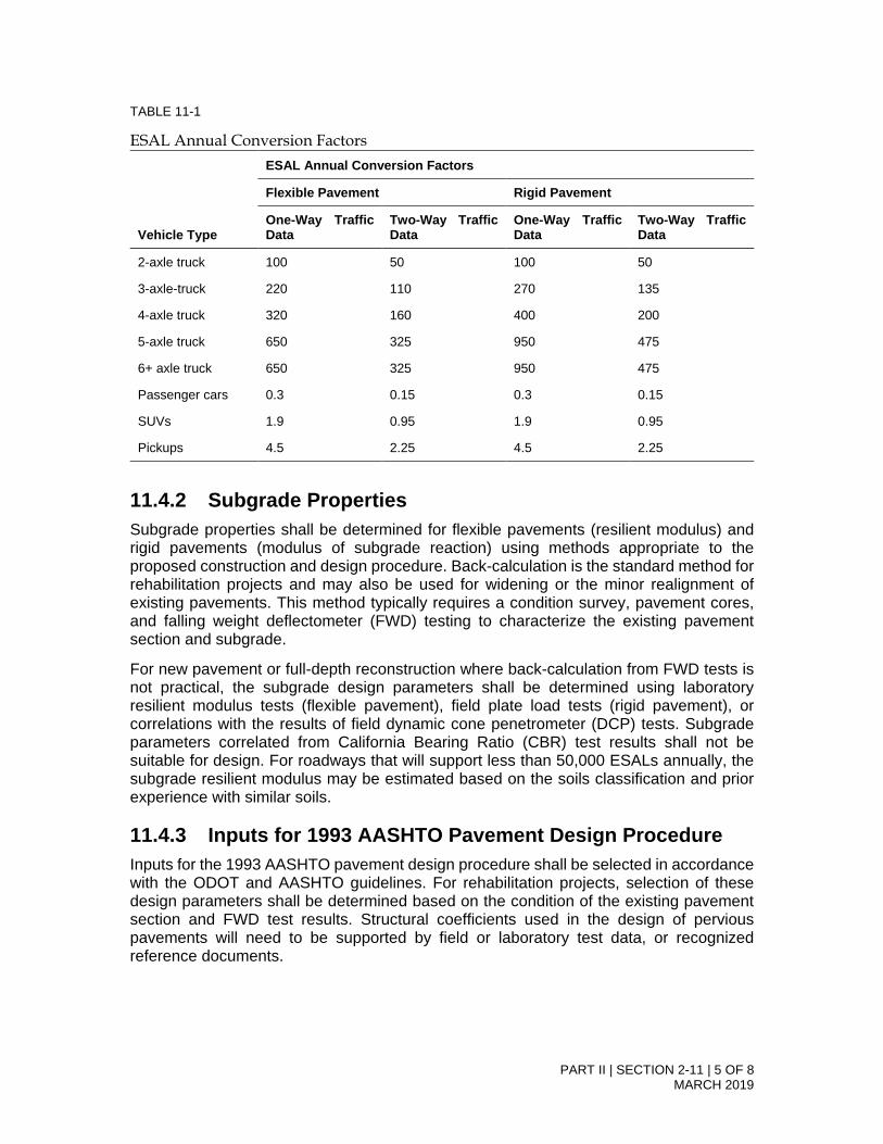
PART II | SECTION 2-11 | 5 OF 8 MARCH 2019
TABLE 11-1
ESAL Annual Conversion Factors
Vehicle Type
ESAL Annual Conversion Factors
Flexible Pavement Rigid Pavement
One-Way Traffic Data
Two-Way Traffic Data
One-Way Traffic Data
Two-Way Traffic Data
2-axle truck 100 50 100 50
3-axle-truck 220 110 270 135
4-axle truck 320 160 400 200
5-axle truck 650 325 950 475
6+ axle truck 650 325 950 475
Passenger cars 0.3 0.15 0.3 0.15
SUVs 1.9 0.95 1.9 0.95
Pickups 4.5 2.25 4.5 2.25
11.4.2 Subgrade Properties Subgrade properties shall be determined for flexible pavements (resilient modulus) and rigid pavements (modulus of subgrade reaction) using methods appropriate to the proposed construction and design procedure. Back-calculation is the standard method for rehabilitation projects and may also be used for widening or the minor realignment of existing pavements. This method typically requires a condition survey, pavement cores, and falling weight deflectometer (FWD) testing to characterize the existing pavement section and subgrade.
For new pavement or full-depth reconstruction where back-calculation from FWD tests is not practical, the subgrade design parameters shall be determined using laboratory resilient modulus tests (flexible pavement), field plate load tests (rigid pavement), or correlations with the results of field dynamic cone penetrometer (DCP) tests. Subgrade parameters correlated from California Bearing Ratio (CBR) test results shall not be suitable for design. For roadways that will support less than 50,000 ESALs annually, the subgrade resilient modulus may be estimated based on the soils classification and prior experience with similar soils.
11.4.3 Inputs for 1993 AASHTO Pavement Design Procedure Inputs for the 1993 AASHTO pavement design procedure shall be selected in accordance with the ODOT and AASHTO guidelines. For rehabilitation projects, selection of these design parameters shall be determined based on the condition of the existing pavement section and FWD test results. Structural coefficients used in the design of pervious pavements will need to be supported by field or laboratory test data, or recognized reference documents.

PART II | SECTION 2-11 | 6 OF 8 MARCH 2019
11.4.4 Minimum Design Life, and Life-cycle Cost Analysis The minimum design life for new pavement sections shall be 20 years and 30 years for flexible and rigid pavements, respectively. Rehabilitated pavement sections shall have a design life of 15 years, or as determined by a life-cycle cost analysis (LCCA) according to AASHTO guidelines. LCCA shall be completed for new pavements and rehabilitation projects to evaluate the costs and benefits of the various pavement types or rehabilitation strategies.
11.4.5 Minimum AC Thickness Refer to Section 3.8.5 Pavement Sections for minimum AC thickness.
11.4.6 Minimum PCC Thickness and Joint Design The minimum Portland cement concrete (PCC) thickness shall be determined according to the procedures of the AASHTO supplement for Rigid Pavement Design & Rigid Pavement Joint Design (1998), or approved equivalent, and rounded up to the nearest 0.5-inch. An increased PCC section may be required at bus stops or at other locations where heavy trucks regularly stop and start. In no case, shall the PCC thickness be less than 5-inches, and all PCC pavement sections should include a base rock section that will provide adequate drainage.
Proper joint design is critical to the performance of PCC pavements and the submitted pavement design shall include an explanation of the selected joint patterns, including applicable references and design criteria.
11.5 Sign, Luminaire, and Signal Pole Foundations in the Public Right of Way
For standard sign, luminaire, and signal poles, the Oregon Department of Transporation standard foundation plans for standard sign, luminaire, and signal pole shall be used where the minimum geotechnical foundation requirements of the plans are met. Where nonstandard signs, luminaires, or signal poles are proposed, or where the geotechnical conditions do not meet the minimum requirements of the standard plans, foundations for the signs, luminaires, and signal poles within the public right-of-way shall be designed in accordance with the AASHTO (2001) Standard Specifications for Structural Supports for Highway Signs, Luminaires, and Traffic Signals.
11.6 Other Transportation Design Elements All other transportation design elements, including but not limited to bridges, culverts, embankments, retaining walls, and cut slopes, shall be designed in accordance with the ODOT (2008) Geotechnical Design Manual, the ODOT (2004) Bridge Design and Drafting Manual, and the AASHTO (2007) Load and Resistance Factor Design Bridge Design Specifications. Abbreviated design efforts may be acceptable for some applications if approved by the City Engineer.

PART II | SECTION 2-11 | 7 OF 8 MARCH 2019
11.7 Blasting All transportation and utility design elements requiring blasting for the excavation of rock shall be designed to prevent damage to existing infrastructure, and avoid unnecessary overbreak of the rock. A precondition survey of nearby structures, private or public, shall be completed prior to the start of blasting, and the blasting program shall include provisions for monitoring of potential damage, or vibrations or noise in excess of permitted levels.
11.8 References Design of facilities for the City of Bend shall meet or exceed the requirements of the following references, or the latest published edition as of the date of CIP contract execution or Initial Development Plan submittal unless otherwise directed in writing by the City Engineer. The documents are listed in order of precedence, should a discrepancy between cited references be identified.
11.8.1 Utility Systems; Pipelines, Appurtenances, and Ancillary Structures
• Oregon Occupational Safety and Health Department (OR-OSHA). Oregon Administrative Rules, Division 3, Subdivision P, Excavations.
• Oregon Department of Transportation/Oregon Chapter of the American Public Works Association (ODOT/APWA). 2008. Oregon Standard Specifications for Construction.
• AWWA 2009. Manual of Water Supply Practices –M41: Ductile-Iron Pipe and Fittings. Third Edition.
• ALA. 2005. Seismic Guidelines for Water Pipelines. March.
• ALA. 2002. Seismic Design and Retrofit of Piping Systems. July.
• Central Oregon Intergovernmental Council (COIC). 2007. Central Oregon Stormwater Manual.
• International Code Council (ICC). 2006. International Building Code.
• ICC. Oregon Structural Specialty Code. 2008.
11.8.2 Transportation Structural Elements; Pavements, Bridges, Culverts, Embankments, Retaining Walls, and Cut Slopes
• ODOT. 2008. Geotechnical Design Manual.
• ODOT. 1987. Soil and Rock Classification Manual.
• ODOT. 2007. Pavement Design Guide.
• ODOT. 2004. Bridge Design & Drafting Manual. Updated April 2009.
• AASHTO. 1993. Guide for Design of Pavement Structures.

PART II | SECTION 2-11 | 8 OF 8 MARCH 2019
• AASHTO 2001. Standard Specifications for Structural Supports for Highway Signs, Luminaires, and Traffic Signals, Fourth Edition.
• AASHTO. 2007. AASHTO Load and Resistance Factor Design Bridge Design Specifications, Fourth Edition. Interim revisions dated 2008 and 2009.

PART II | SECTION 2-12 | PAGE 1 OF 10 MARCH 2019
SECTION 2-12
Landscape Architecture and Irrigation Systems
Table of Contents 12.0 Landscape Architecture and Irrigation Systems ....................................................... 2 12.1 Applicability .............................................................................................................. 2 12.2 Landscape Plan Submittals ...................................................................................... 2
12.2.1 Design Parameters ................................................................................................... 2 12.2.2 Landscape Conservation .......................................................................................... 3 12.2.3 Street Trees and Plants ............................................................................................ 5 12.2.4 Standard Materials and Equipment .......................................................................... 7
12.3 Irrigation Plan Submittals ......................................................................................... 8 12.3.1 Design Parameters ................................................................................................... 8 12.3.2 Drip Irrigation Design ................................................................................................ 9 12.3.3 Standard Materials and Equipment .......................................................................... 9

PART II | SECTION 2-12 | PAGE 2 OF 10 MARCH 2019
12.0 Landscape Architecture and Irrigation Systems
The purpose of these guidelines is to promote community health, safety and welfare by protecting natural vegetation, set development standards for landscaping and street trees, and reduce water consumption through the use of appropriate site design, plant materials, and irrigation technologies. These standards are in addition to and complement the Bend Development Code (BDC) Chapter 3.2, Landscaping, Street Trees, Fences and Walls.
12.1 Applicability The City shall require submittal of Landscape and Irrigation plans for any system that is located within City right-of-way (ROW) and/or will become owned, operated and maintained by the City of Bend and when required by the BDC. All landscape and/or irrigation plans for work within all public ROW shall be stamped and signed by a licensed landscape architect defined by the Oregon Revised Statutes. Minimum general specifications for construction shall be set forth in the Oregon Standard Specifications (OSS) for Construction and these City of Bend Standards and Specifications. The design standards include tree and existing plant habitat protection, removal of trees and landscaping materials, plant selection, tree spacing, as well as the safety of the public and City maintenance staff.
12.2 Landscape Plan Submittals A landscape plan is required to include the following per BDC Chapter 4.2.300 Submittal Requirements:
a. A planting schedule containing the location, size, and species of the existing andproposed plant materials (at time of planting);
b. Existing and proposed building and pavement outlines;c. Irrigation plans, written soil specifications at time of planting, and anticipated plant
installation time line;d. The location of existing and proposed terraces, retaining walls, decks, patios, shelters,
and play areas;e. Existing and proposed abutting street right-of-way landscaping;f. Other information as deemed appropriate by the Development Services Director. An
arborist’s report may be required for sites with mature trees that are protected underBDC Chapter 3.2, Landscaping, Street Trees, Fences and Walls.
12.2.1 Design Parameters The design criteria for public ROW projects shall conform to the current City of Bend specifications, codes and ordinances of the City of Bend. The following are the minimum design standards for the City of Bend. These standards apply to all public ROW projects unless a variance is approved in writing from the City of Bend.

PART II | SECTION 2-12 | PAGE 3 OF 10 MARCH 2019
12.2.1.1 Stormwater Source Control Principles The landscape plan shall adhere to current stormwater quality source control principles for low impact development including but not limited to identifying the development/building envelope, designing with the natural topography, minimizing impervious areas, working to minimize the volume and velocity of stormwater runoff through features such as canopy coverage and infiltration, where appropriate, and incorporating treatment through soils.
12.2.1.2 Water Efficient Landscaping Principles The landscape plan shall adhere to current water conservation principles for water efficient landscape design, including, but not limited to, addressing microclimatic conditions in the site design process, grading, plant selection, soil amendments, irrigation design, and other material selection.
12.2.1.3 Hydrozoning The landscape design shall select and group plants by implementing principles of "matched hydrozones" that is, grouping and watering plants based on their water needs. The City of Bend recognizes four hydrozone classifications as outlined in the Oregon State University Extension Service publication Water-wise Gardening in Central Oregon. The four hydrozones are:
1. Very Low - Most natives / may require supplemental water for plant establishment;2. Low - Perennials and some shrubs / some supplemental water required during the
growing season (Apr - Oct);3. Moderate - Fruit trees, ornamental trees, and shrubs / regular amounts of
supplemental water required during the growing season (Apr - Oct); and,4. High - Turfgrass and vegetable gardens / regular amounts of supplemental water
required during the growing season (Apr - Oct).In addition, the following site-specific situations shall be considered for separating zones:
• Separate zones for planting areas that have soil types that are significantly differentas a result of being amended or disturbed;
• Separate zones for plants in raised planters, containers, tree wells, tree pits, or otherlimited spaces because those spaces dry out faster;
• Separate zones for plants on slopes, because they may require several short irrigationcycles to prevent runoff;
• Separate zones for landscape areas separated by physical barriers such as walls,fences, roads, sidewalks and driveways.
12.2.2 Landscape Conservation Landscape Conservation prevents the indiscriminate removal of significant trees and other vegetation, including vegetation and features associated with streams, riparian areas, wetlands and other protected natural resource areas. Landscape conservation standards apply to all development sites that contain significant vegetation, as defined in the BDC.
12.2.2.1 Tree Protection Plan A Tree Protection Plan is required per BDC Chapter 3.2.200 Landscape Conservation. Significant trees shall be inventoried during the site design process and protected during construction unless otherwise approved for removal through the site plan review process. Significant trees are defined as individual trees with a specific trunk diameter as measured four feet above the ground

PART II | SECTION 2-12 | PAGE 4 OF 10 MARCH 2019
(known as DBH, “diameter at breast height”). Deciduous trees measuring 6 inches or greater and coniferous trees measuring 10 inches or greater shall be considered significant. Significant trees shall be retained unless approved by the City to be removed for development. Preservation will be considered impracticable when it would prevent development of public streets, public utilities, needed housing, or land uses permitted by the applicable land use district. A protection area shall be defined around the edge of all branches of each tree (drip-line) or strand of trees. Drip-lines may overlap between trees. The tree protection plan shall include the following:
a. Inventory of Significant Vegetation. Depict all significant vegetation by DBH andspecies, showing property lines, two-foot contours and rock outcroppings;
b. Building Envelopes. The developer shall depict the buildable area of a lot that isconsistent with the lot coverage area of the zone.
c. Barriers. The developer shall depict protection barriers on the site plan and locate andmark with flagging and/or signs all construction roads, parking places for workers, andareas for the storage of building materials, gravel and soil; stake out the exact locationsof all utility trenches; erect physical barriers around all trees to be retained or groupsof trees around the work site. Barriers that extend beyond the drip-line of the tree arepreferred.
d. Soil Compaction. The Tree Protection Plan shall depict typical details of methods forprotecting the critical root zone. If barriers are not feasible to keep away vehicles andfoot traffic, use six to eight inches of wood chips spread over the root zone or bridgeroot area overlaid by plates of steel or other suitable material.
e. Grade Changes. If a grade change is unavoidable, retaining walls shall be used toprotect the root system.
f. Severing Roots. Avoid cutting anchoring roots if possible. Tunneling for smallerhousehold utility lines may be an option for tree preservation. When root cuts areunavoidable, the cuts shall be made with a pruning saw.
g. Above-Ground Injuries to Trees. Do not use trees for posting signs, electrical wiresand pulleys. Keep trees free of nails, screws, and other fastening devices. Preventtrunk injuries by surrounding trunk with one-inch by four-inch wooden slats andsecuring in place with gauge wire around slats.
h. Soil Contamination. Altering the soil chemistry can result in weakened trees, makingthem more susceptible to insects and disease. Prevent adverse effects on soilchemistry by spreading heavy plastic tarping where concrete is to be mixed or sheetrock cut; do not clean paintbrushes and tools over tree roots; dispose of chemicalwastes properly and do not drain onto soil.
i. Altering the Natural Drainage Course. When the natural drainage of a site is altered,watering for existing trees must be augmented by an irrigation system. Prior to sitegrading, prepare a site drainage plan. Sometimes surface water containment cansustain existing stands of trees without artificial irrigation.
Landscape plans or specifications shall note a requirement for the City to be notified within 24 hours of any damage to existing trees within the project area that were not approved for removal or relocation. If damage occurs during construction, the contractor shall employ a certified arborist to determine whether the damage may be repaired or the tree replaced according to City standard mitigation procedures.

PART II | SECTION 2-12 | PAGE 5 OF 10 MARCH 2019
12.2.2.2 Tree Removal and Relocation Trees shall not be removed or relocated within the public ROW without approval from the City Engineer. The applicant shall submit a Tree Removal and Planting Permit application to the City of Bend that identifies number and type of trees to be removed, location of trees to be removed, reason for removal, and proposed planting mitigations. Approval for removal/relocation of the tree shall require approval from the City Engineer based on the following criteria: (1) the site cannot feasibly be developed, either by alternative site design or construction methods without removing or relocating existing trees; (2) trees left in their present location will be so undermined by construction that their viability is threatened to the extent they become a danger in the future; or (3) the existing location is determined to interfere with the clear vision standards, intersection sight triangles, and intersection sight distances (for traffic, bicycles, and/or pedestrians and causes a safety concern that may not be resolved by appropriate pruning or thinning). Recommendations for removal, pruning or thinning must be made by a licensed landscape architect or certified arborist. Under no circumstances may a tree be “topped”. Existing trees approved for removal or relocation shall be clearly identified on the landscape plan. The City shall be notified 48 hours in advance of any approved tree removal activity.
12.2.3 Street Trees and Plants Street trees shall be required to be located and planted with all public-ROW projects. They may be located within the ROW as indicated in 14.3.9, or located in the front yard setback or buffer area immediately adjacent to the ROW, as stated in the BDC Chapter 3.2.400, Street Trees. Deviation from this standard shall require approval from the City Engineer. Trees and plant species selected for use in non-paved public ROW projects shall be selected for their durability, drought tolerance, proportionality to site circumstances, low maintenance, and clearance standards for pedestrian, bicycle, and vehicular traffic safety. The publication titled “Water-wise Gardening in Central Oregon” by the Oregon State University Extension Service is recommended as a guidebook for plant selection. Copies of the publication are available at the City of Bend Utility Department and OSU Extension Service. All trees and plants considered shall be hardy to USDA Zone 3 – 5 or 6b.
12.2.3.1 Approved Street Tree List Proposed street trees shall be selected from BDC Chapter 3.2.400 Street Trees, unless otherwise approved by the Planning Director.
12.2.3.2 Non-approved Street Trees and Plants Turf and artificial turf is prohibited in public ROW projects, but will be assessed by the City of Bend on a case-by-case basis.
12.2.3.3 Height Standards for Street Trees and Plants On public ROW landscape projects without existing sidewalks, trees shall be located to accommodate future sidewalk locations with consideration for existing and future utility corridors. Plants that will attain a mature height of two feet or more in height should not be planted in Clear Vision Areas, Intersection Sight Triangles, nor Sight Distance Areas. Refer to drawing R-2, Clear Vision Areas, and Part II, Section 3.3.4.3. The height of the plant shall include the adjacent curb height and any earthwork or grading within the plant bed.

PART II | SECTION 2-12 | PAGE 6 OF 10 MARCH 2019
Trees are not permitted to be planted within the Clear Vision Area, Intersection Sight Triangles, nor Sight Distance Areas. Existing trees shall be limbed to a minimum of 8 feet above the adjacent curb. This applies to center medians as well as roadside areas. Only trees, 25-feet high or less, at maturity, shall be considered for planting under or within 10-lateral feet of any overhead utility lines.
12.2.3.4 Size of Street Trees and Plants Minimum plant and tree sizes are to be determined by the BDC Chapter 3.2.300. Shrubs shall be planted from two-gallon containers or larger. The minimum caliper size of street trees at planting shall be two and one-half inches (2.5”) DBH (diameter at breast height, or four feet above ground), based on the American Association of Nurserymen Standards. If the required caliper is not available, the Planning Director/Review Authority may accept replacement trees with an extended maintenance guarantee of two additional years depending on substituted size.
12.2.3.5 Street Tree Location and Spacing Street trees must be planted within existing and proposed planting strips or in City-approved sidewalk tree wells on streets without planting strips. Street trees planted within sidewalk tree wells shall must be installed with a City-approved tree grate. Where the landscape strip and/or sidewalk is not wide enough to accommodate street trees, the Planning Director may allow the street trees to be planted within five feet from the back of the sidewalk. Where practical, small stature trees must be planted no closer to the curb or sidewalk than three feet, medium trees – three feet and large trees – four feet. Root barriers may be required with street tree planting to protect the City’s curb and sidewalk. Street tree spacing must be based upon the type of tree(s) selected and the canopy size at maturity. Small canopy trees and columnar shaped trees must be planted no further than 25 feet apart; medium and large canopy trees must be planted no further than 35 feet apart, except where planting a tree would conflict with existing trees, retaining walls, utilities and similar physical barriers. A random spacing of street trees may be approved for the equivalent number of trees required for the length of the frontage. Trees should be spaced no less than the following distances from existing or planned infrastructure:
• Stop signs: 35 feet;
• Street lights: 25 feet;
• Non-street light utility poles: 5 feet;
• Property lines: 2 feet;
• Fire hydrants: 10 feet;
• Water meters or sampling manholes: 5 feet;
• Driveways, sidewalks, curbs, or alleys: 3 feet for small and medium trees, 4 feet forlarge trees;
• Traffic signs: 20’; and,
• Bus benches and shelters: 5’

PART II | SECTION 2-12 | PAGE 7 OF 10 MARCH 2019
Trees shall not be planted within the following areas:
• Clear vision areas;
• Intersection sign triangles;
• Sight distance areas;
• City water or sewer easements, unless approved by the City Engineer;
• Public utility easements, unless written approval is obtained from the applicableagenc(ies); or,
• Medians less than 4 feet wide.
12.2.3.6 Exemptions Exceptions and/or exemptions to tree and plant location standards will be considered on a case-by-case basis, as approved by the City Engineer and/or Planning Director.
12.2.4 Standard Materials and Equipment Designs shall incorporate materials and equipment that comply with the City of Bend Standards and Specifications. Alternative materials shall only be used when an approved Deviation from Standards and Specifications request has been submitted and approved.
12.2.4.1 Tree Wells Street trees planted within sidewalk tree wells shall be installed within a pedestrian rated tree grate or surrounded by permeable pavers or pavement appropriate for pedestrian circulation. The minimum tree pit dimensions shall be a minimum of 108 cubic feet 4 ft. x 9 ft., minimum 3 feet deep, and a minimum surface dimension of 4 feet.
12.2.4.2 Soil Amendments The City of Bend requires the use of organic soil amendments to improve soil structure and increase aeration, water penetration, and water retention for plant hydration when appropriate for the selected plant species. An agricultural soil analysis shall be required for all public works projects. Soil analysis shall include pH, N-P-K, SAR, ECe, boron levels, percolation rates and soil particle evaluation. The report shall include recommendations for amendments, fertilizers, application rates, and procedures for conditioning the soil. Soil amendments shall be tilled to an appropriate depth for the planting in order to prevent a layering of soil types. Existing native shrub zones shall not be disturbed by soil amendment processes.
12.2.4.3 Mulches Organic mulch such as shredded bark or composted bark shall be applied to all planting areas for moisture retention, weed control, and moderation of soil temperatures. Impermeable weed barriers made of plastic are prohibited under any mulches. Woven geotextile products are allowed under gravel or rock mulches. The landscape plan shall identify the proposed type and recommended depth of installation for all proposed mulch materials.
12.2.4.4 Fertilizers The landscape plan or specifications shall specify any additional fertilization requirements that may be necessary for the establishment of new plant material.

PART II | SECTION 2-12 | PAGE 8 OF 10 MARCH 2019
The landscape plan shall specify type and recommended application rate for each proposed use of any fertilizer recommendation that deviates from the Bend Standards and Specifications, Section 10130-Seeding, and Section, 01040-Planting, for approval by the City.
12.3 Irrigation Plan Submittals Irrigation systems shall be designed to be efficient and to uniformly distribute water. Specific criteria that shall be considered in designs include soil type, slope, root depth, plant materials, hydrozones, microclimate conditions, water source, peak precipitation rate demand, and watering windows. To conserve and protect water resources, designs shall utilize appropriate equipment and components that meet the City of Bend Codes, Standards and Specifications. Irrigation designs should strive to design projects that are aesthetically pleasing, conserve water resources, and reduce required maintenance by City staff. For capital improvement and development projects, the following design requirements shall be implemented in all design deliverables and submittals presented to the City of Bend for review. An irrigation plan shall accompany the site/landscape plan and identify the location, type, and coverage of sprinklers, as well as drip lines, valves, zones, point(s) of connection and other equipment required to provide water as prescribed by the City of Bend as part of the submittal to the City for review and approval prior to installation. An irrigation plan is required for any public development where landscaping within the City of Bend right-of way is part of the improvements, either new or existing. Irrigation plans shall be in compliance with these standards and those set forth in OSS and in other Bend Codes, Standards, and Specifications. See Chapter 2 for plan submittal requirements and City of Bend CAD Standards.
12.3.1 Design Parameters Irrigation systems shall be designed to fully irrigate plant materials shown or specified on the site plan. System design should consider plant size and spacing at maturity to ensure long term effectiveness. The minimum supply water pressure shall be based on information supplied by the water utility, field-verified and noted on the drawings. Irrigation systems shall be designed to maximize efficient water usage based on existing and proposed site– specific topography, soils, site orientation, prevailing wind conditions, and micro-climates to eliminate the possibility of run-off and overspray, minimize evaporation, and increase the rate of infiltration. Overhead irrigation sprinklers shall be inset 3-5” from hardscape, curbs and sidewalks to prevent irrigation overspray and runoff onto adjacent surfaces. Ensure the irrigation system adheres to Bend Code 14.20 Use of Water and does not result in irrigation overspray or runoff onto adjacent hard surfaces. Irrigation designs shall not mix rotary, fixed spray, bubblers, microsprays, drip, or subsurface irrigation methods on the same zone. Provide separate irrigation zones for trees shrubs & groundcovers, and turf. Fixed spray or rotary head irrigation may be used for “temporary irrigation zones”. Temporary irrigation is required to establish areas being revegetated with drought-tolerant and native plant species. Temporary irrigation systems shall be reviewed on a case-by-case basis and removed after the vegetation is established. Irrigation designs shall identify location, number of zones, and irrigation types proposed for any areas determined to be temporary irrigation zones.

PART II | SECTION 2-12 | PAGE 9 OF 10 MARCH 2019
Separate zones are required for permanent and temporary irrigation lines.
12.3.1.1 Safety Run-off and/or over-spray from sprinkler heads shall be eliminated from streets and sidewalks by use of proper design principles and installation practices. Refer to Bend Code 14.20.030 Water Waste Defined for additional information about water waste. To conserve and protect water quality, all landscapes and irrigation installations shall consider the conservation of resources, and protect native habitats and watersheds. Irrigation designs shall utilize products that require the least amount of service, repair, and replacement. Buried vaults and valves should be located near areas with low pedestrian and vehicular traffic.
12.3.1.2 Hydrozones The irrigation plan, in conjunction with the landscape plan, shall prevent over-watering and under-watering by implementing principles of "matched hydrozones.” Refer to Section Part II, Chapter 12.2.1.3 for additional detail.
12.3.1.3 Hydraulic Calculations Irrigation designs shall supply complete calculations for all irrigation zones (drip zones and spray zones separately). Supply a table showing the total water required for each zone to ensure that the design has not exceeded the maximum for the meter, proposed pipe size, and zone watering times.
12.3.2 Drip Irrigation Design Use drip irrigation when practical and where potential for irrigation overspray and/or runoff is likely to occur. Drip irrigation systems shall be designed according to standards and engineering practices specified by the American Society of Agricultural and Biological Engineers or Irrigation Association. Systems should be designed to meet the changing water requirements of the landscape as it matures. Drip irrigation is required where dimensions are less than six feet in any direction. Overhead irrigation in areas greater than six feet in dimension shall utilize low-precipitation rate sprinkler nozzles and have a precipitation rate of less than 1.0 inch per hour. Drip irrigation systems shall be designed so that the drip emitters have an ‘Emission Uniformity’ (relative flow rate between like emitters) of at least 80 percent at time of installation.
12.3.3 Standard Materials and Equipment Designs shall incorporate materials and equipment that comply with City of Bend Standard Specifications and OSS for Irrigation Systems, Section 01120. Alternative materials shall only be used when an approved Deviation from Standards and Specifications request has been submitted and approved. Materials shall be designated by trade name as per City of Bend Special Provisions or an approved equal, as verified from information in the manufacturer’s catalogue and shown to contain comparable components.
12.3.3.1 Irrigation Controllers The City of Bend uses the current technology for programming and monitoring irrigation systems for landscape areas within the city to ensure the most efficient delivery of water to the public ROW. Irrigation controllers shall be EPA WaterSense labeled smart irrigation controllers that automatically adjust irrigation run times in response to environmental conditions.

PART II | SECTION 2-12 | PAGE 10 OF 10 MARCH 2019
12.3.3.2 Automatic Control Valves Automatic electric solenoid remote control valves shall be slow acting diaphragm-type, as per Bend Standards and Specifications, 01120.17 Valves (h) Control Valves, (2) Automatic Control Valves.
12.3.3.3 Sprinkler Heads Sprinkler heads shall provide coverage as specified in the manufacturer’s design literature. The use of high efficiency sprinklers or nozzles is encouraged wherever practicable.
12.3.3.4 Pipe ROW projects shall be entirely furnished with one pipe class or schedule type as per the Bend Standards and Specifications, and conforming to all other national and local standards.
12.3.3.5 Blowouts A blowout connection point shall be installed to facilitate winterization by use of compressed air. Locate blowout connection immediately downstream from backflow device.
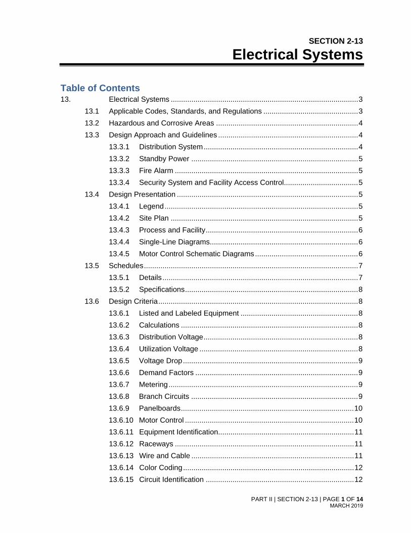
PART II | SECTION 2-13 | PAGE 1 OF 14 MARCH 2019
SECTION 2-13
Electrical Systems
Table of Contents 13. Electrical Systems ........................................................................................... 3
13.1 Applicable Codes, Standards, and Regulations .............................................. 3 13.2 Hazardous and Corrosive Areas ..................................................................... 4 13.3 Design Approach and Guidelines .................................................................... 4
13.3.1 Distribution System ........................................................................... 4 13.3.2 Standby Power ................................................................................. 5 13.3.3 Fire Alarm ......................................................................................... 5 13.3.4 Security System and Facility Access Control .................................... 5
13.4 Design Presentation ........................................................................................ 5 13.4.1 Legend .............................................................................................. 5 13.4.2 Site Plan ........................................................................................... 5 13.4.3 Process and Facility .......................................................................... 6 13.4.4 Single-Line Diagrams........................................................................ 6 13.4.5 Motor Control Schematic Diagrams .................................................. 6
13.5 Schedules ........................................................................................................ 7 13.5.1 Details ............................................................................................... 7 13.5.2 Specifications .................................................................................... 8
13.6 Design Criteria ................................................................................................. 8 13.6.1 Listed and Labeled Equipment ......................................................... 8 13.6.2 Calculations ...................................................................................... 8 13.6.3 Distribution Voltage ........................................................................... 8 13.6.4 Utilization Voltage ............................................................................. 8 13.6.5 Voltage Drop ..................................................................................... 9 13.6.6 Demand Factors ............................................................................... 9 13.6.7 Metering ............................................................................................ 9 13.6.8 Branch Circuits ................................................................................. 9 13.6.9 Panelboards .................................................................................... 10 13.6.10 Motor Control .................................................................................. 10 13.6.11 Equipment Identification.................................................................. 11 13.6.12 Raceways ....................................................................................... 11 13.6.13 Wire and Cable ............................................................................... 11 13.6.14 Color Coding ................................................................................... 12 13.6.15 Circuit Identification ........................................................................ 12

PART II | SECTION 2-13 | PAGE 2 OF 14 MARCH 2019
13.6.16 Enclosures ...................................................................................... 13 13.6.17 Fiber-optic Cable ............................................................................ 13 13.6.18 Grounding ....................................................................................... 13 13.6.19 Lighting ........................................................................................... 13 13.6.20 Street Lighting ................................................................................. 14

PART II | SECTION 2-13 | PAGE 3 OF 14 MARCH 2019
13. Electrical Systems
General street lighting designs shall comply with City of Bend standards and the utility company providing the power guidelines. The designer shall coordinate the design with both entities prior to submission for plan approval.
NFPA 70 is the National Electrical Code (NEC) that has been adopted by the State of Oregon and the City of Bend. The State of Oregon Electrical Specialty Code is based on the NEC, with additions to and amendments of specific NEC Articles that are pertinent to the State of Oregon. Information on the Oregon Electrical Specialty Code and interpretations may be obtained from the Oregon Building Codes Division.
NFPA 820, Standard for Fire Protection in Wastewater Treatment and Collection Facilities, includes the hazard classifications of specific areas and processes. The hazard classifications coincide with mandatory NEC requirements for the design of electrical systems, equipment, and materials in areas and for processes classified as hazardous.
13.1 Applicable Codes, Standards, and Regulations
Codes are legal documents whose use is determined by the Authority Having Jurisdiction (AHJ). Requirements of the current NEC as amended by the current State of Oregon Electrical Specialty Code are to be satisfied in all electrical designs. Additional codes, the current versions of which apply to all electrical designs, include:
• NFPA 70E, Standard for Electrical Safety in the Workplace• NFPA 101, Life Safety Code• ANSI C2, National Electrical Safety Code• International Building Code (IBC)• International Fire Code (IFC)
Standards are recommendations that form design guidelines that are not legal in nature, but are considered “standard practice.” Standards organizations, the applicable current versions of which apply to all electrical designs, include:
• American National Standards Institute (ANSI)• National Electrical Manufacturers Association (NEMA)• Institute of Electrical and Electronics Engineers (IEEE)• Instrument Society of America (ISA)• Insulated Cable Engineers (ICEA)• American Society for Testing and Materials (ASTM International)• Underwriters Laboratories, Inc. (UL)• Illuminating Engineering Society (IES)• National Electrical Contractors Association (NECA)• International Electrical Testing Association (NETA)
Regulations are legal design standards that must be incorporated into designs. Regulations, the applicable sections of which apply to all electrical designs, include:

PART II | SECTION 2-13 | PAGE 4 OF 14 MARCH 2019
• Occupational Safety and Health Act (OSHA)• Americans with Disabilities Act (ADA)
13.2 Hazardous and Corrosive Areas Hazardous areas and processes are classified in NFPA 820. The classification tables include a description of the location and function; the fire and explosion hazard; ventilation requirements if the initial classification is to be reduced; extent of the classified area; NEC area electrical classification (all Class I, Group D) with “Division 1”, “Division 2”, or “Unclassified” listed as applicable; materials of construction for buildings or structures; and fire protection measures. Hazardous area classifications (Class, Division, Group) are to be noted on applicable electrical drawings with the requirement to “furnish, install, and connect electrical devices and materials in these areas per NEC Article 501 (Class I locations) requirements.”
For all hazardous areas the designer shall specify type 316 stainless steel, NOT type 304 stainless steel, for all interior and exterior corrosive and/or wet areas. All hardware necessary to install electrical systems including supports and fasteners shall be 316 SST. Note on applicable electrical drawings those areas that are corrosive and/or wet with the requirement to “furnish, install, and connect electrical devices and materials in these areas per NEC Article 300.6 (protection against corrosion and deterioration) requirements.”
13.3 Design Approach and Guidelines The electrical design shall satisfy all code requirements, and when codes, standards, or regulations conflict, the design is to comply with the more stringent requirements.
13.3.1 Distribution System The facility power distribution system voltage shall be based on the connected load and what is available from the electric utility. Available electric service voltages are:
• 480Y/277 volts, 3-phase, 4-wire• 480 volts, 3-phase, 3-wire• 240/120 volts, 3-phase, 4-wire• 240 volts, 3-phase, 3-wire• 120/240 volts, 1-phase, 3-wire
The electric service up to 200 amps is required to be routed through a utility revenue meter box and socket. Above 200 amps, a separate electric utility current transformer (CT) cabinet is required with secondary conduit to the meter box and socket.
On the load side of the meter box or CT cabinet, provide a main circuit breaker located in either a separate enclosure or a motor control center (MCC) lineup. The main circuit breaker and its enclosure or MCC compartment are required to be UL labeled “suitable for use as service equipment.”
A standby power supply or provisions for standby power is required. Provide a transfer switch on the load side of the main circuit breaker, which is connected to the electric utility “normal” power source and when the “normal” power source is de-energized, can be switched to an “alternate” power source standby engine generator. The transfer switch enclosure shall be individually mounted or included in an MCC lineup.

PART II | SECTION 2-13 | PAGE 5 OF 14 MARCH 2019
On the load side of the transfer switch, provide the electric load power control equipment; for example, motor starters [and power factor correction capacitors (PFCCs) as applicable]; adjustable frequency drives (AFDs), power panelboards, feeder circuit breakers, etc. The power control equipment shall be either in individual enclosures or in a MCC lineup.
13.3.2 Standby Power Provide standby power at all pump stations, reservoirs, etc., unless directed otherwise by the City Engineer in writing. The standby “alternate” power source shall be a stationary standby engine generator hardwired to an automatic transfer switch (ATS). An uninterruptible power supply (UPS) is another “alternate” power source, which relies on rechargeable batteries, to power critical panelboards for instrumentation, control, and supervisory control and data acquisition (SCADA) systems.
Standby engine generators shall be diesel-fueled with a subbase fuel tank under the engine generator skid inside an overall sound-attenuated, weatherproof enclosure. Natural gas or propane may also be used, depending on availability and Owner preference.
13.3.3 Fire Alarm If directed by the Owner, provide a system with fire alarm control panel, addressable ionization smoke or infrared sensors, manual pull stations, and alarm strobe light/horns with provisions to activate an automatic telephone dialer to alert the local fire department.
13.3.4 Security System and Facility Access Control Security systems shall consist of a door key pad, which activates the door lock. Magnetic door switches are provided in the door frame and door at the top of the door to alarm when the door is forced opened without key pad authorization. Doors shall also have a key lock.
13.4 Design Presentation 13.4.1 Legend Provide an electrical legend and abbreviations drawing. If a standard legend and abbreviations are used, edit out all symbols and abbreviations that are not applicable to the design. If new symbols or abbreviations are used on the drawings, add them to the legend and abbreviations.
13.4.2 Site Plan Provide an electrical site plan that locates the electric service entrance equipment and existing and/or new equipment provided by the electric utility to provide electric service to the facility. Show the routing of the electric utility service (overhead or underground) to the service entrance equipment. Show stationary standby engine generator or mobile standby engine generator receptacle, all exterior electrical loads (pumps, odor control equipment, etc.), control and/or instrumentation devices, site lighting, receptacles (remote from a building or outdoor control panel), etc., and the routing of underground conduits to them.

PART II | SECTION 2-13 | PAGE 6 OF 14 MARCH 2019
13.4.3 Process and Facility Provide building process and facility plan(s) and/or exterior pump wet well process and facility plans(s) with associated freestanding control panel(s). On process plans, show the location of the electric service entrance equipment (utility meter and main circuit breaker), automatic transfer switch, MCC and/or individually mounted motor starters (and PFCCs), AFDs, panelboards, transformers, etc. On facility plans, show the location of heating, ventilating, and air conditioning (HVAC) equipment, indoor and outdoor luminaires, light switches, telephone terminal cabinet or mounting panel, other non-process equipment, etc.
13.4.4 Single-Line Diagrams Provide a single-line diagram that schematically shows power source(s) and electrical loads. Power source items include the normal (utility) power source and utility metering, service entrance main circuit breaker, standby power source engine generator or mobile standby engine generator receptacle, standby power source circuit breaker, ATS or MTS, surge arrester [transient voltage surge suppressor (TVSS)], and local metering. Electrical load items include motor starters (and PFCCs), AFDs, feeder circuit breakers, stepdown transformers, panelboards, etc.
Some ATSs are available with normal and standby molded case thermal magnetic circuit breakers, load-side metering, and have a UL “suitable for use as service equipment” label. These service entrance ATSs are acceptable instead of separate main and standby circuit breakers, ATS, and metering. All of the above items may be shown in individual enclosures or in a common MCC lineup.
Show all circuit breaker ratings and combination circuit breaker NEMA full-voltage starter sizes. Provide molded case motor circuit protector (instantaneous-trip) type circuit breakers shown “XX/M”, where “XX” is the current rating, for motor starters for motors up to 60 horsepower. Provide molded case thermal magnetic type circuit breakers for motor starters for motors larger than 60 horsepower and for all other circuit breakers. For metering, provide a switched voltmeter and ammeter or digital power meter.
13.4.5 Motor Control Schematic Diagrams Provide motor control motor starter and/or AFD schematic control diagrams that include the motor starter/AFD circuit breaker; all control functions and interfaces, and the motor connection. Use the basic combination motor starter and/or AFD control diagram and add additional control features as required. Refer to Subsection “Design Criteria/Motor Control” for additional requirements.
Additional control features shall include interlocks between motor starters/AFDs to allow operation of less than the total number of pumps when the standby power source is powering the facility. Additional features may include a Flygt MiniCAS thermal/ moisture module or equivalent by other suppliers and motor connections, motor shutdown, reset, and alarm light for motor high temperature, and alarm light for motor moisture detection. Additional features may include an ON/OFF/AUTO selector switch with provisions for automatic operation from an ultrasonic (Siemens/Milltronics) level sensor. Additional features may also include a manual or automatic AFD bypass motor starter in case the AFD fails.

PART II | SECTION 2-13 | PAGE 7 OF 14 MARCH 2019
Motor starter/AFD status lights shall include a red “MOTOR RUNNING” and amber alarm lights. Status and alarm lights should be the push-to-test LED type. Motor starter/AFD output alarms to an automatic phone dialer or SCADA system should include “NOT IN AUTO,” “OVERLOAD SHUTDOWN”, “MOTOR HIGH TEMPERATURE SHUTDOWN”, “MOISTURE IN MOTOR,” and “AFD FAIL” alarms as applicable.
Submersible pump switch rated disconnect switch receptacles and plugs shall be manufactured by Meltric Corporation, Franklin, WI, and shall be used for disconnecting and removing submersible pumps. Specify the receptacles/plugs on the Motor Control Schematic Diagrams. On the site or wet well plan, mount the receptacles 24 inches above the top of the wet well top slab to a mounting structure near the submersible pump(s) access hatch. Core drill a hole through the top of the precast concrete wet well top. The hole must be slightly larger than the plug diameter. Note on the site plan to provide an O.Z./Gedney Type CSBE Segmented Conduit Sealing Bushing to seal the submersiblepump power/control cable penetration through the top slab into the wet well.
13.5 Schedules Provide schedules for luminaires, manholes/handholes, and ultrasonic level sensor settings as required. Recommended luminaire schedule column headings include:
• Symbol and type number• Input voltage (120V, 277V, etc.)• Input Watts (includes ballast and luminaire)• Description of luminaire• Manufacturer and model number used as basis for design• Lamp quantity, type (fluorescent, HPS, etc.), and color temperature or wattage• Mounting (wall, ceiling, pendant, etc.)
Manhole/handhole column headings include:
• Manhole/handhole tag number
• Minimum inside dimensions (L, W, H)
• Drawing where manhole/handhole is located
• Manufacturer and catalog number
Ultrasonic controller (ULC) pump start/stop and alarm setpoint headings include:
• Pump/alarm identification (wetwell overflow, wetwell high level, lead pump on, lagpump on and alarm, etc.)
• ULC setpoint relay number
• Wet well elevation
• Remarks (pump start, alarm, etc.)
13.5.1 Details Provide details as required to show underground conduit installation, conduit/cable penetration through the concrete slab, equipment pad (for MCC), pole-mounted site light,

PART II | SECTION 2-13 | PAGE 8 OF 14 MARCH 2019
pedestal mounting frame for submersible pump disconnect receptacles, etc. Provide additional project-specific details as required.
13.5.2 Specifications Edit the standard electrical specifications as required for the specific project. Delete equipment, materials, and installation that are not applicable to the specific project. Add requirements for additional equipment, materials, installation, etc., as required.
13.6 Design Criteria 13.6.1 Listed and Labeled Equipment Materials and equipment shall be specified and installed in accordance NFPA 70, the NEC. Materials and equipment shall be labeled or listed by a nationally recognized testing laboratory or other organization acceptable to the AHJ, in order to provide a basis for approval under the NEC. Materials and equipment manufactured within the scope of standards published by Underwriters Laboratories, Inc., shall conform to those standards and shall have an applied UL listing mark or label.
13.6.2 Calculations Calculations shall be made and documented for each project to establish electrical equipment current and circuit breaker ratings and conductor and conduit sizes. Based on full-load current ratings provided by process and facility equipment suppliers, calculate the size of power conductors and conduits to the equipment per the NEC Chapter 9 tables for the specified conductor and conduit types. Using NEC Article 430.24, calculate the size of the main power conductors and conduits to the electrical equipment that powers the process and facility equipment. Using NEC Article 430.62, calculate the current rating of the electrical equipment main service entrance circuit breaker and ATS or MTS.
13.6.3 Distribution Voltage The project distribution voltage is established to some extent by the project equipment horsepower requirements and the voltage available at the project site by the local electrical utility. The utility may only have 120/240-volt, single-phase power available in residential or rural areas, and 3-phase power (480Y/277V or 240/120V) available in urban industrial areas. Because it is desirable to keep equipment current requirements low to reduce wire sizes, a rule of thumb would be for a 120/240-volt single-phase 3-wire or 240/120-volt, 3-phase, 4-wire electric service to provide up to a service rating of 100 to 200 amps.Electric service ratings at 480Y/277 volts, 3-phase, 4-wire when available are satisfactoryat any reasonable electric service current ratings. Although the utility service is listed at480Y/277 volts, 3-phase, 4-wire with grounded neutral, the actual electric utility servicevoltage at the project electric service connection shall be 480 volts, 3-phase, 3-wire;neutral not required.
13.6.4 Utilization Voltage The utilization voltage on pump station, reservoir, etc., projects is the same as the distribution voltage. For projects powered at 480 volts, 3-phase, 3-wire, low-voltage instrumentation and control, facility, lighting, and receptacle circuits should be powered
PART II | SECTION 2-13 | PAGE 9 OF 14 MARCH 2019
from a 208Y/120 volt, 3-phase, 4-wire panelboard via a 480-208Y/120 volt transformer to minimize voltage unbalance.
13.6.5 Voltage Drop Branch circuit voltage drop calculations, where required for heavily loaded and/or long feeder and/or branch circuit distances, shall comply with NEC Article 210.19(A)(1), Exception No. 2, Fine Print Note (FPN) No. 4, which states:
Conductors for branch circuits as defined in Article 100, sized to prevent a voltage drop exceeding 3 percent at the farthest outlet of power, heating, and lighting loads, or combinations of such loads, and where the maximum total voltage drop on both feeders and branch circuits to the farthest outlet does not exceed 5 percent, provide reasonable efficiency of operation.
Make a voltage drop calculation for motor starting whenever an individual motor exceeds 20 percent of the serving transformer capacity.
13.6.6 Demand Factors General guidelines for electrical load demand factors are as follows:
• Lighting 1.0 x connected load
• Emergency lighting 1.0 x connected load
• HVAC equipment 1.0 x connected load
• Sump pumps 0.5 x connected load
• Convenience receptacles 180 VA each
• Process loads 1 x full load amps of non-standby loads plus 25% of largest motor
Provide 10 to 20 percent spare capacity at MCCs and panelboards.
13.6.7 Metering The electric utility revenue meter is provided by the electric utility for installation in a meter socket and box provided as part the project design. On the line side of the ATS or MTS, provide a voltmeter and 4- or 7-position selector switch with line-to-line, line-to-neutral, and OFF positions and an ammeter and 3- or 4-position selector switch with line and OFF positions. A digital power meter with the same measuring capabilities as the voltmeter and ammeter may be provided instead of the meters.
13.6.8 Branch Circuits General guidelines for branch circuits are as follows:
• Use the connected load and NEC requirements for sizing branch circuit breakers,conductors, and conduits.
• Use a minimum wire size of No. 12 American Wire Gauge (AWG) copper forlighting and receptacle branch circuits. Use No. 10 AWG wire when voltage droprequires a larger conductor on lighting circuits, and when receptacle circuits arelonger than 75 feet.

PART II | SECTION 2-13 | PAGE 10 OF 14 MARCH 2019
• Where electronic ballasts are specified for fluorescent or high-intensity dischargelighting, provide a dedicated neutral for each lighting circuit; NO common neutralfor multiple lighting circuits.
• In general, lighting branch circuit loads shall be limited to 1,500 watts.
• Light and receptacle branch circuits shall not be combined.
• The number of convenience receptacles on any one branch circuit shall be limitedto five duplex receptacles rated 120V, 20 amps. Where weatherproof, ground faultcircuit interrupter (GFCI) duplex receptacles are required, each receptacle shall bea GFCI receptacle. GFCI feed through receptacles shall not be used.
13.6.9 Panelboards General guidelines for panelboards are as follows:
• The panelboard and branch circuit breakers shall be identified by branch circuit orfeeder homeruns shown on the drawings.
• Each panelboard shall be equipped with a minimum of 20 percent spare branchcircuit breakers with spaces, bus work, and terminations to complete the standardsize panelboard.
• Prepare panelboard schedules that include identification of the device powered bythe branch circuit, protective device trip rating, number of poles (branch circuitbreaker), load in volt-amps by phase, rating of main lugs or main circuit breaker,neutral bus size, ground bus size, and integrated short circuit rating of thepanelboard.
• Provide a separate panelboards for instrumentation and control (I&C) devices andfield panels, if needed.
13.6.10 Motor Control Refer to Subsection “Design Presentation/Motor Control Schematic Diagrams” for content, and prepare motor control diagrams per these requirements:
• Prepare elementary (ladder type) control diagrams for each motor showing wiring,pilot devices, auxiliary contacts and external connections. A single control diagrammay be used for more than one motor having the same control.
• Use electrical symbols shown on the electrical legend sheet. Identify eachcomponent with a unique letter or name. Show wiring and devices inside thecontroller (motor starter or AFD MCC compartment or separate enclosure) withsolid lines, and wiring and devices remote from the controller with dashed lines.Indicate the location of remote devices by symbol or description.
• Show remote control assemblies that have complex internal wiring as dashedrectangles. Identify only the interconnecting terminals or interface, and referencethe location of the remote control assembly or who is responsible for the internalwiring.

PART II | SECTION 2-13 | PAGE 11 OF 14 MARCH 2019
13.6.11 Equipment Identification Instrumentation and control (I&C) process and instrumentation diagrams (P&IDs) are required unless directed otherwise by the City. Use P&ID tag numbers for motors, I&C devices, and other process equipment shown on electrical drawings. Use this same numbering method to create unique tags for major electrical equipment.
If I&C P&IDs are not required, develop unique tag numbers for process, facility, and electrical equipment using abbreviations from the Abbreviations List on the Electrical Legend & Abbreviations Drawing and a unique number suffix as needed [for example, MCC, ATS or MTS, EF (exhaust fan), P1 (Pump No. 1), P2, etc.].
13.6.12 Raceways Inside buildings and electrical control panels, route power, control, and instrumentation circuits in rigid galvanized steel conduits. Outdoors direct buried conduits, conduits under slabs, conduits concrete-encased in slabs, and conduits exposed in wetwells shall be:
• Schedule 40 PVC for power and 120-volt control circuits and fiber optic cables.• PVC-coated rigid steel for low control (less than 120V) and analog circuits.• Schedule 40 PVC for all exposed conduits in wetwells and channels.
General guidelines for raceway sizing, selection, and installation are as follows:
• Base conduit sizing on THW insulated conductors.• Use these minimum conduit sizes:
− 3/4-inch diameter for conduit installed exposed on walls and ceilings− 3/4-inch diameter for conduit concealed in frame construction and finished
ceilings − 1-inch for conduit embedded in masonry, encased in concrete, and
underground
• Route raceways exposed in process areas.
• Use PVC-coated rigid galvanized steel conduit for the transition from undergrounddirect burial PVC, underslab PVC, and concrete-encased PVC. The galvanizedsteel transition section shall extend from 1 foot below grade or top of floor slab orthe last foot of conduit in the floor slab, to 6 inches out of the floor slab, concreteencasement, or above grade connection.
• Limit the number of conduit bends to an equivalent of 270 degrees in long runswithout pullboxes.
• Identify underground conduit routes with nonmetallic warning tape undergroundabove the direct buried conduits.
13.6.13 Wire and Cable General guidelines for wire and cable are as follows:
• Use stranded copper conductors for all except lighting and receptacle wiring. Usesolid copper conductors #10 AWG or #12 AWG for lighting and receptacle wiring.

PART II | SECTION 2-13 | PAGE 12 OF 14 MARCH 2019
• Use #14 AWG as the minimum conductor size for individual 120-volt controlcircuits.
• Use #12 AWG as the minimum conductor size for 120-volt control circuits routedin a common conduit with the power conductors to the motor circuit controls at themotor. Combine individual motor circuit power and control conductors in a commonconduit up to a maximum power conductor size of #2 AWG.
• Under normal conditions, limit the maximum wire size to 500 kcmil. Use parallelconductors for circuits requiring greater capacity.
• Combine 120-volt control circuits in 600 volt multiconductor control cablescontaining multiple #14 AWG stranded copper conductors. Use control cableswhere grouping control circuits is practical and the number of individual wiresexceeds six conductors. When selecting control cable size, provide 25 percentspare (plus or minus 10 percent) conductors.
13.6.14 Color Coding Conductor insulation colors shall be as shown below:
System Conductor Color
All systems Equipment grounding Green
120/240 volts Grounded neutral White
Single-phase, 3-wire One hot leg Other hot leg
Black Red
208Y/120 volts Grounded neutral White
3-phase, 4-wire Phase A Phase B Phase C
Black Red Blue
240/120 volts Grounded neutral White
3-phase, 4-wire Phase A Black
Delta, center tap High (wild) leg Orange
Ground on single-phase Phase C Blue
480Y/277 volts Grounded neutral White
3-phase, 4-wire Phase A Phase B Phase C
Brown Orange Yellow
13.6.15 Circuit Identification Circuit names shall be based on the device or equipment at the load end of the circuit. The circuit shall be identified at each termination and in accessible manholes, handholes, and pull boxes. Use plastic sleeves for conductors #3 AWG and smaller, and plastic marker plates for larger conductors. For lighting and receptacle circuits, the panel and circuit number shall be identified at each luminaire and receptacle.

PART II | SECTION 2-13 | PAGE 13 OF 14 MARCH 2019
13.6.16 Enclosures General guidelines for electrical equipment enclosure types are as follows:
• NEMA 1 – Equipment in electrical rooms and finished areas
• NEMA 12 – Equipment in dry industrial locations
• NEMA 4X (Type 316 Stainless Steel) – Equipment in wet and/or corrosivelocations
• NEMA 7 –Equipment in Classified hazardous locations
13.6.17 Fiber-optic Cable Where used, provide fiber optic cabling in 2-inch-diameter conduit, minimum, and provide large radius conduit bends to prevent breaking fibers in the fiber optic cable.
13.6.18 Grounding Provide a ground ring around the building and stationary standby engine generator equipment pad or the electrical control panel equipment pad at the site. The ground ring shall consist of a #6 AWG bare copper ground wire and at least two ground rods. Connect conductors from the ground grid to each end of the MCC ground bus and the neutral of any 208Y/120-volt distribution transformer secondary. Ground rods shall be 3/4-inch in diameter by 10 feet long copper-clad steel installed 20 feet apart, minimum. If bedrock is encountered, the ground rod must be installed by drilling a 4-inch-diameter hole and installing the ground rod in a graphite-based grout backfill material.
Provide a separate ground conductor sized in accordance with NEC requirements in raceways for power feeders and branch circuits for power, control, lighting and receptacle circuits.
13.6.19 Lighting Provide interior and exterior areas with lighting. Interior lights shall include switched lights, emergency egress standby lights, and exit lights if required. Emergency standby and exit lights will each include a battery charger and battery. Exterior lighting shall include photocell-controlled or switched lights mounted on buildings near doors or on poles or structures. Design must comply with City light pollution reduction standards.
Fluorescent luminaires shall be used in all interior locations. Fluorescent “enclosed and gasketed” luminaires of non-metallic construction shall be used for applications in damp, wet, or corrosive locations or locations exposed to the weather and unprotected and shall be specified to be UL labeled “suitable for wet locations.”
High-pressure sodium (HPS) luminaires shall be used for all exterior lighting. Luminaires shall be powered at 120 volts and controlled by a photocell. Exterior lighting shall have sharp cutoff shrouds to limit the migration of light. Exterior lighting shall be controlled by an ON/OFF/AUTO selector switch and roof- or wall-mounted photocell. In the AUTO mode, lights turn on at dusk and off at dawn via the photocell.

PART II | SECTION 2-13 | PAGE 14 OF 14 MARCH 2019
13.6.20 Street Lighting
13.6.19.1 General As part of the public improvement process, a street illumination design shall be included with all project plans submitted to the City, as well as a power plan from the utility company providing the power. The street illumination design shall clearly show where the luminaires, conduit runs, junction boxes, service cabinets, and power sources will be located. Design must comply with City light pollution reduction standards.
13.6.19.2 Conduit Size Conduits shall be sized according to the requirements of the NEC current edition.
All conduit runs shall be as direct from point to point as possible, shall remain within the rights-of-way, and maintain as straight an alignment as possible.
The minimum conduit size shall be one inch. All conduits under the roadway shall be a minimum of 2- inches in diameter. Conduits placed on Pacific Power utility poles will require ‘stand-off’ mountings and need to be specified in whole inch diameters. All conduit runs shall be clearly indicated on the plans showing the route from the power source (typically a vault) to the street light.
A junction box shall be included at each end of roadway conduit crossings.
13.6.19.3 Conductor Size A catalog cut sheet with maximum starting and operating amperages information shall be included in the plans submittal to verify the wire sizing calculations.
A circuit diagram and load calculations shall be included on the plan sheets at the end of the lighting construction drawings.
The maximum voltage drop shall be two percent from the utility to the service equipment and three percent from the service to the farthest load.
Any suitable method for calculating voltage drop and conductor sizes may be used. Provide reference to any source of information.
Junction boxes shall be placed near the base of each light pole. If the power source is within twenty feet of the street light, this junction box will not be required. All junction boxes used for the street lighting system shall have the words STREET LIGHTING displayed on the metal lid.
All electrical conductors shall be THWN with a minimum size of Number 12 AGW. A continuous, ground/bonding wire shall be used in all raceways (conduits) and sized according to the Code requirements.
PART II | SECTION 2-14 | PAGE 1 OF 8 MARCH 2019
SECTION 2-14
Instrumentation and Control Systems Table of Contents 14. Instrumentation and Control Systems ......................................................................... 2
14.1 Scope .............................................................................................................. 2 14.1 References – City of Bend Standard Specifications ........................................ 2 14.2 Design Deliverables ......................................................................................... 2
14.2.1 Legend ............................................................................................................. 2 14.2.2 Process and Instrumentation Diagrams .......................................................... 2 14.2.3 Process Control Functional Narratives ............................................................ 3 14.2.4 PLC I/O List ..................................................................................................... 4 14.2.5 Control System Block Diagram ........................................................................ 4 14.2.6 Sample Loop Drawings ................................................................................... 5 14.2.7 Instrument List ................................................................................................. 5
14.3 Design Criteria ................................................................................................. 5 14.3.1 Enclosures ....................................................................................................... 5 14.3.2 PLC I/O Special Requirements ........................................................................ 6 14.3.3 Typical PLC I/O at Remote Station Facilities ................................................... 6 14.3.4 Tag Numbering ................................................................................................ 7 14.3.5 Network Communication ................................................................................. 7 14.3.6 Radio Pathway Study ...................................................................................... 8 14.3.7 Instruments and Components ......................................................................... 8 14.3.8 Testing Requirements ..................................................................................... 8
ATTACHMENT 1 - SAMPLE P&ID ATTACHMENT 2 – SAMPLE PROCESS CONTROL NARRATIVE ATTACHMENT 3 – SAMPLE PLC I/O LIST ATTACHMENT 4 – SAMPLE LOOP DRAWING

PART II | SECTION 2-14 | PAGE 2 OF 8 MARCH 2019
14. Instrumentation and ControlSystems
14.1 Scope This document is intended to provide guidance for pump stations, reservoirs, and other remote station facilities with process control functions. HVAC systems are exempt, except when required by the City Engineer.
14.1 References – City of Bend Standard Specifications
Refer to the following City of Bend standard specifications for additional requirements:
• Section 01 91 14B –Equipment Testing, Facility Startup, and Commissioning• Section 40 91 00 –Instrumentation and Control Components
14.2 Design Deliverables 14.2.1 Legend Provide an I&C legend drawing to identify all P&ID symbols and abbreviations used on the project. The legend shall include at minimum all graphical symbols used for major equipment (pumps, motors, valves, instruments, vessels, etc.), a summary of flow streams used on P&ID process piping, a table to define the unit process numbers used on the project, a line legend to identify the uses of different line types on the P&IDs, and a table to identify all abbreviations used on the P&IDs (PLC, UPS, etc).
If a standard legend drawing is used, remove all symbols and abbreviations that are not applicable to the design. If new symbols or abbreviations are used on the drawings, add them to the legend and abbreviations.
14.2.2 Process and Instrumentation Diagrams Provide complete P&IDs for the project. If multiple P&ID drawings are required, organize them by site, facility, or process. Show process flow from left to right.
P&IDs shall include the following minimum data:
• Major process components, vessels, and piping
• Equipment tags and descriptions for all major process components and vessels
• Flow stream identification on all process piping
• Flow directional arrows on all process piping

PART II | SECTION 2-14 | PAGE 3 OF 8 MARCH 2019
• Text next to each pump and motor to identify it as adjustable speed (AS) or constantspeed (CS)
• Fail position of all valves (FO = fail open, FC = fail closed, FLP = fail last position)
• All major instruments identified by a tagname consisting of Instrument Society ofAmerica (ISA) instrument code, unit process number, and loop number (includesanalytical, flow, level, pressure, and temperature instruments, as well ashandswitches and indicating lights)
• Power supply voltage for all major process components, instruments, and panels
• Adjustable frequency drives
• All handswitches and indicating lights mounted on MCC bucket doors, controlpanels, and field control stations
• PLC I/O:
− Use graphical symbols to differentiate between analog inputs, analog outputs,discrete inputs, and discrete outputs. Identify the I/O function with text (ON, FAIL, RUN, FLOW, PRESSURE, etc.).
− Show signal lines between the I/O point graphical symbols and the interfacing field equipment. Use a different line type to differentiate between analog and discrete signals.
14.2.3 Process Control Functional Narratives Provide written process control functional narratives to define all control system software functions to be programmed by the system integrator. Organize the process control functional narratives by site, facility, unit process and loop number. Include the following minimum information:
• Provide a written summary of the control loop operation, including field interlocks thataffect software control of equipment
• Define all data to be displayed at the graphical interface, including but not limited toequipment status, alarms, and process variables
• Define all operator controls to be provided at the graphical interface, including usersetpoints, selectors, and pushbuttons
• Define all calculations to be performed by the control system software
• Define all equipment software interlocks
• Define all alarms to be generated and displayed
• Identify the priority of all alarms generated by the system
• Define all data to be communicated between PLCs via networks or radio (peer data viamessage blocks)

PART II | SECTION 2-14 | PAGE 4 OF 8 MARCH 2019
14.2.4 PLC I/O List Provide a list to summarize all PLC inputs and outputs associated with the project. For each control panel, summarize the quantity of each I/O type used on the project (# of analog inputs, # of analog outputs, # of 24VDC discrete inputs, etc). The list shall include the following minimum data:
• Software tag – Identify the software tag to be used in the graphical interfacesoftware. The software tag shall include the ISA component code or equipmentabbreviation, unit process number, loop number and software function.
• I/O type
− AI for analog input − AO for analog output − DI-24 for discrete input, 24VDC− DI-120 for discrete input, 120VAC− DO–24 for discrete output, 24VDC − DO-120 for discrete output, 120VAC − ENT-AI for Ethernet-communicated analog input − ENT-AO for Ethernet-communicated analog output − ENT-DI for Ethernet-communicated discrete input − ENT-DO for Ethernet-communicated discrete output
• I/O module – Identify the part number of the I/O module to which the point is wired.
• Description – Provide a description of the equipment or system to which the I/Opoint is related. For example, “well pump 1,” “wetwell level,” or “pump 1 flow.”
• ON state – For discrete I/O points, provide a text description to identify the meaningof the point when it is energized in the software. For example, “RUN,” “HIGH,”“OPEN,” or “ON.”
• OFF state – For discrete I/O points, provide a text description to identify the meaningof the point when it is de-energized in the software. For example, “STOP,” “NOTHIGH,” “CLOSED,” or “OFF.”
• Range – For analog I/O points, provide the numerical range over which the value willchange. For example, “0-100%,” “1-14 (pH)”, or “0-3000 gpm.”
• Physical location
− Rack – The PLC rack in which the I/O module is located − Slot – The rack’s slot location of the module to which the I/O point is wired − Point – The point number on the module to which the I/O point is wired
14.2.5 Control System Block Diagram If network or radio communications are used on the project, provide a control system block diagram to show connectivity of all communication system components, including network switches, media converters, communication modules, and terminating resistors. Identify the destination of communication lines that interface with the project components but are outside the project scope (for example, radio communications to an existing repeater).

PART II | SECTION 2-14 | PAGE 5 OF 8 MARCH 2019
Distinguish between different types of communication media (fiber optic cable, CAT5 or CAT6 copper, coaxial cable, etc.) using different line types or text. Identify all network addresses on the drawing, including station radio addresses and Ethernet network Internet Protocol (IP) addresses. Note that it may be necessary to coordinate with the City’s IT staff for network address assignments.
14.2.6 Sample Loop Drawings Detailed loop drawings shall be generated by the general contractor’s system integrator based on samples provided in the design documents. Provide sample loop drawings to demonstrate City of Bend standard wiring concepts, drawing format, and level of detail. Major concepts to be included in the loop drawings include the following:
• I/O location, including PLC, rack, slot, point number, and I/O module part number
• Wire and cable tag
• Wire color
• I/O point software address, equipment description, and ON state description (fordiscrete I/O) or range (for analog I/O)
• Terminal block identifier and terminal number
• Associated circuit protection (circuit breakers and fuses)
• Analog signal cable shielding
• All associated terminations at PLC panel and field components
14.2.7 Instrument List Provide an instrument list to identify the required parameters for all instruments associated with the project. Include the instrument type, instrument tag number, and loop description for all instruments, and organize the list by unit process and loop number. Provide the measurement range for all analog instruments. Provide initial setpoints or mounting elevations for all switches.
14.3 Design Criteria 14.3.1 Enclosures
14.3.1.1 General Where enclosures contain voltages exceeding 120VAC, provide a main circuit breaker disconnect interlocked with the panel door. All enclosures shall be UL Listed.
14.3.1.2 Outdoor Application Provide lockable stainless steel enclosures mounted on a shade structure for all outdoor applications. Include specification text requiring panel fabricators to provide enclosure temperature control for the following environmental conditions to protect temperature-sensitive components located inside the panel:

PART II | SECTION 2-14 | PAGE 6 OF 8 MARCH 2019
• Ambient temperature range: Minus 5-degrees F to 110-degrees F
• Protected from direct overhead mid-day sunlight and falling rain/snow by overheadshelter
• Exposed to wind, blowing rain, and blowing snow
• Exposed to morning and evening sun
Provide all operator indication and control devices on an inner door (behind the lockable door). At wastewater pump stations, a flashing alarm beacon shall be provided on top of the enclosure.
14.3.1.3 Indoor Application Provide NEMA 12 enclosures in indoor dry locations. Provide NEMA 3R enclosures in normally dry indoor locations where pipe breakage could result in water spray onto the panel.
14.3.2 PLC I/O Special Requirements
14.3.2.1 Discrete Inputs Use 24VDC for all discrete inputs.
14.3.2.2 Discrete Outputs Use dry contact output modules dual rated for 24VDC and 120VAC. Use 24VDC for discrete outputs, where possible, but it is acceptable to use PLC discrete output module dry contacts in 120VAC motor control circuits.
14.3.2.3 Analog I/O Use 4-20mA current signals for all PLC analog I/O.
14.3.2.4 Spares Provide at least 25 percent spare points for each I/O type used. Provide a minimum of three spares for analog I/O types and eight spares for discrete I/O types.
14.3.3 Typical PLC I/O at Remote Station Facilities
14.3.3.1 Common I/O for All Remote Stations Provide the following PLC I/O at all remote stations:
• DI: Utility Power FAILURE• DI: 24VDC Power Supply FAILURE
14.3.3.2 Typical PLC I/O at Wastewater Lift Stations Provide the following minimum PLC I/O at all wastewater lift stations:
• AI: Wetwell LEVEL• AI: Lift Station Effluent FLOWRATE

PART II | SECTION 2-14 | PAGE 7 OF 8 MARCH 2019
• DI: Wetwell Level HIGH-HIGH• DI: REMOTE control mode for each lift station pump• DI: ON status for each lift station pump• DI: FAIL status for each lift station pump
14.3.3.3 Typical PLC I/O at Freshwater Reservoirs This shall include flow meters in and out. Provide the following minimum PLC I/O at all freshwater reservoirs:
• AI: Reservoir LEVEL
14.3.3.4 Typical PLC I/O at Freshwater Pump Stations Provide the following minimum PLC I/O at all freshwater pump stations:
• AI: Pump Station Effluent FLOWRATE• DI: REMOTE control mode for each lift station pump• DI: ON status for each lift station pump• DI: FAIL status for each lift station pump
14.3.3.5 Typical PLC I/O at Freshwater Wells Provide the following minimum PLC I/O at all wastewater lift stations:
• AI: Well LEVEL• AI: Well Effluent FLOW• AI: Chlorine Residual• DI: REMOTE control mode for each well pump• DI: ON status for each well pump• DI: FAIL status for each well pump
14.3.3.6 Typical PLC I/O at Pressure Monitoring Stations Provide the following minimum PLC I/O at all pressure monitoring stations:
• AI: System PRESSURE
14.3.4 Tag Numbering Provide tag numbers for all major process components and instruments. All tags shall include unit process number and loop number. Process component tags shall include a component code to identify the type of equipment (example: “P” for pump, “M” for motor). Instrument tags shall include the ISA code for the instrument type (“LSH” for high-level switch, “FIT” for flow indicating transmitter, etc.).
14.3.5 Network Communication • Variable frequency drives – The City uses Ethernet for communication between
variable frequency drives (VFDs) and PLC. Refer to the City’s standard electricalspecification for VFD requirements.
• Media – Use fiber optic cable where communication media is required to be routedoutside a building or enclosure. Copper media (CAT6 cable, coax) is acceptablewithin a building or enclosure.

PART II | SECTION 2-14 | PAGE 8 OF 8 MARCH 2019
• Radio – The City uses radio for communication between remote sites and SCADACentral. Coordinate the approach for radio system design requirements, includingradio pathway study, with the City’s project manager.
14.3.6 Radio Pathway Study Where not provided by the City, provide a radio pathway study to select and/or confirm a radio path for communication between the remote station and the central monitoring station or a repeater. The radio pathway study will confirm that radio communications can be successfully achieved with acceptable fade margin using the City’s chosen frequency. The results of the pathway study will be used to determine radio system requirements including antenna height and signal routing (need for use of repeaters, etc.).
A radio pathway study is generally required only for remote stations with new radio links, unless the City is experiencing difficulty with existing radio communication or is planning to change radio frequency or signal routing.
14.3.7 Instruments and Components Question for City: Let us know if you have specific manufacturer/model preferences so we can list them in these subsections.
14.3.7.1 Common Instrumentation for All Remote Stations Use magnetic flowmeters for flow measurement.
14.3.7.2 Wastewater Lift Stations Provide a submersible pressure transducer for wetwell level monitoring and control. Provide a float switch for high-high level alarming.
14.3.8 Testing Requirements
Refer to Bend standard specification “Equipment Testing, Facility Startup, and Commissioning” for requirements.

ATTACHMENT 1
PART II | SECTION 2-14 | ATT 1
ATTACHMENT 1
Sample P&ID
Attachment 1: Sample P&ID
PART II | SECTION 2-14 | ATT 2
ATTACHMENT 2
Sample Process Control Narrative
CONTROL NARRATIVES
TABLE OF CONTENTS
DIGESTER SLUDGE XFER PUMPS 1, 2, AND 3 ............................................................... 1
Sludge Transfer Pump Suction Pressure ................................................................. 1
Sludge Transfer Pump Discharge Pressure ............................................................. 1
Sludge Transfer Pump Flow Valve ........................................................................... 2
Sludge Transfer Pump ............................................................................................. 3

PART II | SECTION 2-14 | PAGE 1 OF 6
Digester Sludge Transfer Pumps 1, 2, and 3
Sludge Transfer Pump Suction Pressure
Loop Numbers
• 63-013 (Transfer Pump No. 1 Suction Pressure)
• 63-023 (Transfer Pump No. 2 Suction Pressure)
• 63-033 (Transfer Pump No. 3 Suction Pressure)
Loop Description
A pressure switch is provided at each pump’s suction to detect a LOW pressure condition. The pressure switch provides a contact closure to the PLC for remote monitoring and control.
SCADA Functions
The PLC will monitor the switch position for detection of a low suction pressure condition. The PLC will generate a LOW SUCTION PRESSURE alarm immediately upon detection (no alarm delay timer). The alarm can be disabled by operators via the HMI graphics.
HMI Status Monitoring (typical for each pump):
• Sludge Transfer Pump Suction Pressure LOW (alarm)
HMI Control Interface
• Sludge Transfer Pump Discharge Pressure Alarm ENABLE/DISABLE
• Sludge Transfer Pump Discharge Pressure
Loop Numbers
• 63-011 (Transfer Pump No. 1 Discharge Pressure)
• 63-021 (Transfer Pump No. 2 Discharge Pressure)
• 63-031 (Transfer Pump No. 3 Discharge Pressure)
Loop Description
A pressure measurement is provided at each pump’s discharge. The pressure transmitters provide 4-20mA analog input to the PLC for remote monitoring and control.
SCADA Functions
The PLC will calculate HIGH and LOW alarms based on operator entered alarm set points:
• LOW alarm setpoint (initial setpoint) = 10-psi
• HIGH alarm setpoint (initial setpoint) = 60-psi
The associated pump must be running as a condition for both HIGH and LOW alarm calculation. LOW alarm calculation is disabled for the first 5 minutes of pump running to allow the pump to ramp to a sufficient speed to build discharge pressure. Alarm generation will be delayed based on an operator-adjustable alarm delay setpoint to prevent nuisance

PART II | SECTION 2-14 | PAGE 2 OF 6
alarming (the same alarm delay setpoint is used for both high and low alarms). The alarms can be disabled by operators via the HMI graphics.
HMI Status Monitoring (typical for each pump)
• Sludge Transfer Pump Discharge PRESSURE
• Sludge Transfer Pump Discharge Pressure LOW (alarm)
• Sludge Transfer Pump Discharge Pressure HIGH (alarm)
HMI Control Interface
• Sludge Transfer Pump Discharge Pressure ALARM DELAY SETPOINT (0-180 seconds)
• Sludge Transfer Pump Discharge Pressure Alarm ENABLE/DISABLE
• Sludge Transfer Pump Flow Valve
Loop Numbers
• 63-012 (Transfer Pump No. 1 Flow Valve)
• 63-022 (Transfer Pump No. 2 Flow Valve)
• 63-032 (Transfer Pump No. 3 Flow Valve)
Loop Description
A motor-operated butterfly valve is provided on each pump’s discharge for use as a check valve.
SCADA Functions
PLC control will be enabled when READY status is indicated by the valve actuator (REMOTE is selected at the valve’s field mode selector and the valve’s “MR” contact is closed).
Monitoring and Control Interface
The HMI control popup will be based on the existing “p_HW AM PDS P1 Iso Vlv” popup from the Headworks system.
Control Mode Selection
Operators will select the SCADA control mode (AUTO/MANUAL) at the HMI graphics.
Manual Control
Operators will manually control the valve’s operation using OPEN and CLOSE pushbuttons on the HMI graphics:
• The valve will travel to the fully open position when the OPEN pushbutton is pressed.
• The valve will travel to the fully closed position when the CLOSE pushbutton is pressed.
Auto Control
The PLC will automatically control the valve’s operation, as outlined below:
• When a sludge transfer pump is called to start, the PLC will start the pump immediately.Opening of the associated flow (check) valve will be delayed based on an operator-entered delay timer (flow valve OPEN DELAY timer).
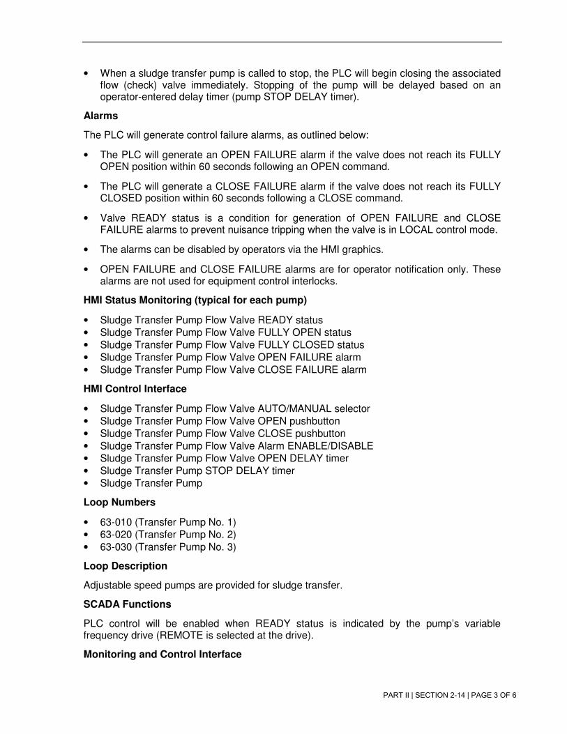
PART II | SECTION 2-14 | PAGE 3 OF 6
• When a sludge transfer pump is called to stop, the PLC will begin closing the associatedflow (check) valve immediately. Stopping of the pump will be delayed based on anoperator-entered delay timer (pump STOP DELAY timer).
Alarms
The PLC will generate control failure alarms, as outlined below:
• The PLC will generate an OPEN FAILURE alarm if the valve does not reach its FULLYOPEN position within 60 seconds following an OPEN command.
• The PLC will generate a CLOSE FAILURE alarm if the valve does not reach its FULLYCLOSED position within 60 seconds following a CLOSE command.
• Valve READY status is a condition for generation of OPEN FAILURE and CLOSEFAILURE alarms to prevent nuisance tripping when the valve is in LOCAL control mode.
• The alarms can be disabled by operators via the HMI graphics.
• OPEN FAILURE and CLOSE FAILURE alarms are for operator notification only. Thesealarms are not used for equipment control interlocks.
HMI Status Monitoring (typical for each pump)
• Sludge Transfer Pump Flow Valve READY status
• Sludge Transfer Pump Flow Valve FULLY OPEN status
• Sludge Transfer Pump Flow Valve FULLY CLOSED status
• Sludge Transfer Pump Flow Valve OPEN FAILURE alarm
• Sludge Transfer Pump Flow Valve CLOSE FAILURE alarm
HMI Control Interface
• Sludge Transfer Pump Flow Valve AUTO/MANUAL selector
• Sludge Transfer Pump Flow Valve OPEN pushbutton
• Sludge Transfer Pump Flow Valve CLOSE pushbutton
• Sludge Transfer Pump Flow Valve Alarm ENABLE/DISABLE
• Sludge Transfer Pump Flow Valve OPEN DELAY timer
• Sludge Transfer Pump STOP DELAY timer
• Sludge Transfer Pump
Loop Numbers
• 63-010 (Transfer Pump No. 1)
• 63-020 (Transfer Pump No. 2)
• 63-030 (Transfer Pump No. 3)
Loop Description
Adjustable speed pumps are provided for sludge transfer.
SCADA Functions
PLC control will be enabled when READY status is indicated by the pump’s variable frequency drive (REMOTE is selected at the drive).
Monitoring and Control Interface

PART II | SECTION 2-14 | PAGE 4 OF 6
The HMI control popup will be based on the existing “p_HW AM Drain Sump Pump 1” popup from the Headworks system.
RUN Control Mode Selection:
Operators will select the SCADA RUN control mode (AUTO/MANUAL) at the HMI graphics.
RUN Control – Manual
Operators will manually control the pump’s operation using START and STOP pushbuttons on the HMI graphics:
• The pump will run when the START button is pressed.
• The pump will stop when the STOP button is pressed.
• Automatic interlocks are disabled in manual control mode (suction pressure alarminterlocks, discharge pressure alarm interlocks, check valve position interlocks, etc).
RUN Control – AUTO
The PLC will automatically control the pump’s operation, as outlined below:
• The automatic control functions depend upon the pump’s chosen sludge destination, asoutlined below. Operators select the sludge destination for each transfer pump using anexisting HMI control graphic. The mode options are NONE, BOILER 1, BOILER 2, orDEWATERING.
− NONE: The pump will not run.
− BOILER 1 mode: The pump will run continuously.
− BOILER 2 mode: The pump will run continuously.
− DEWATERING mode: The pump will run when called by the solids system. Thesolids system logic, including the message block for peer-to-peer PLCcommunication and the software address for the run request for each pump arealready configured.
• INTERLOCKS: The following interlocks will impact automatic run operation regardless ofthe sludge destination selected:
− When a sludge transfer pump is called to start, the PLC will start the pumpimmediately. Opening of the associated flow (check) valve will be delayed based onan operator-entered delay timer (flow valve OPEN DELAY timer).
− When a sludge transfer pump is called to stop, the PLC will begin closing theassociated flow (check) valve immediately. Stopping of the pump will be delayedbased on an operator-entered delay timer (pump STOP DELAY timer).
− Any of the following alarms will stop the pump and lock it out from re-starting untiloperators reset the alarm using the RESET button on the associated pump controlpopup at the HMI graphics:
• Suction pressure LOW
• Discharge pressure LOW
• Discharge pressure HIGH

PART II | SECTION 2-14 | PAGE 5 OF 6
• INTERLOCKS: The following interlocks will impact automatic run operation only whenBOILER 1 or BOILER 2 sludge destination is selected:
− Immediately stop the sludge transfer pump when its associated grinder fails to start.The grinder start failure interlock is ignored if the grinder is bypassed (operatorselection on grinder control popup in HMI graphics).
SPEED Control Mode Selection
Operators will select the SCADA SPEED control mode (AUTO/MANUAL) at the HMI graphics.
SPEED Control –MANUAL
Operators will manually control the pump’s speed using a SPEED SETPOINT (0-100%) on the HMI graphics.
SPEED Control –AUTO
The automatic speed control functions depend upon the pump’s chosen sludge destination, as outlined below.
• NONE: The pump will not run.
• BOILER 1 mode: The pump will run at 100% speed.
• BOILER 2 mode: The pump will run at 100% speed.
• DEWATERING mode: The pump will run at the speed requested by the solids system.The solids system logic, including the message block for peer-to-peer PLCcommunication and the software address for the speed request for each pump arealready configured.
Alarms
The PLC will generate control failure alarms, as outlined below:
• The PLC will generate a START FAILURE alarm if the pump does not start within 10seconds following a RUN command.
• The PLC will generate a STOP FAILURE alarm if the pump does not stop within 10seconds following a STOP command.
• The alarms can be disabled by operators via the HMI graphics.
• START FAILURE and STOP FAILURE alarms are for operator notification only. Thesealarms are not used for equipment control interlocks.
Special Functions
The PLC will track each pump’s RUNTIME based on its ON status indication to the PLC. The runtime counter will roll over (auto-reset) at 10,000 accumulated hours, but it may also be manually reset via a pushbutton on the HMI graphics.
HMI Status Monitoring (typical for each pump)
• Sludge Transfer Pump READY status
• Sludge Transfer Pump ON status

PART II | SECTION 2-14 | PAGE 6 OF 6
• Sludge Transfer Pump FAILURE status
• Sludge Transfer Pump START FAILURE status
• Sludge Transfer Pump STOP FAILURE status
• Sludge Transfer Pump SPEED
• Sludge Transfer Pump RUNTIME
HMI Control Interface
• Sludge Transfer Pump Run Control AUTO/MANUAL selector
• Sludge Transfer Pump START pushbutton
• Sludge Transfer Pump STOP pushbutton
• Sludge Transfer Pump Speed Control AUTO/MANUAL selector
• Sludge Transfer Pump SPEED SETPOINT
• Sludge Transfer Pump Alarm ENABLE/DISABLE
• Sludge Transfer Pump Alarm RESET pushbutton
• Sludge Transfer Pump RUNTIME RESET

PART II | SECTION 2-14 | ATT 3
ATTACHMENT 3
Sample PLC I/O List

PART II | SECTION 2-14 | ATT 3

PART II | SECTION 2-14 | ATT 3

PART II | SECTION 2-14 | ATT 4
ATTACHMENT 4
Sample Loop Drawing
Attachment 4: Sample Loop Drawing