part ii. energy efficiency by sectors energy efficiency in...
TRANSCRIPT
Energy Efficiency
in
Boilers & Steam System
Prepared by: Assoc. Prof. Sengratry KYTHAVONE
Department of Mechanical Engineering, Faculty of Engineering
National University of Laos
1
ODA-UNESCO Project:
” Promotion of Energy Science Education for Sustainable Development in Laos:”
Part II. Energy Efficiency by Sectors
Introduction to Boiler
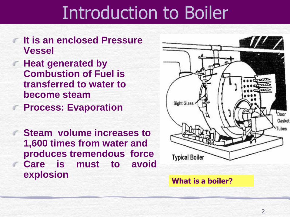
What is a boiler?
It is an enclosed Pressure Vessel
Heat generated by Combustion of Fuel is transferred to water to become steam
Process: Evaporation
Steam volume increases to 1,600 times from water and produces tremendous force Care is must to avoid explosion
2
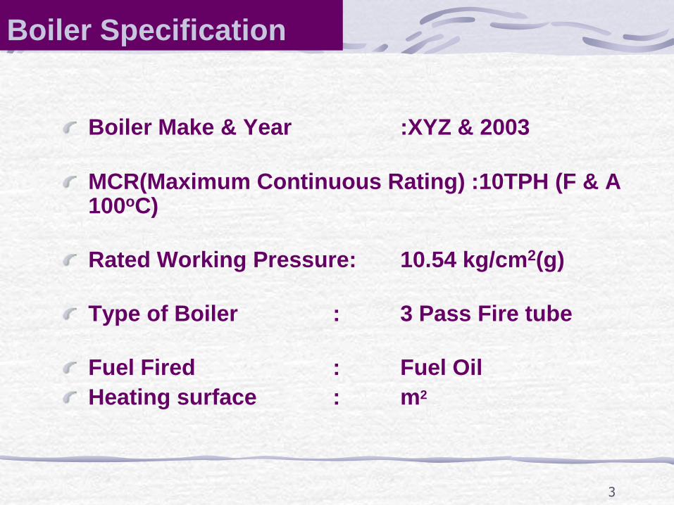
Boiler Make & Year :XYZ & 2003
MCR(Maximum Continuous Rating) :10TPH (F & A 100oC)
Rated Working Pressure: 10.54 kg/cm2(g)
Type of Boiler : 3 Pass Fire tube
Fuel Fired : Fuel Oil
Heating surface : m2
Boiler Specification
3
Boiler Systems
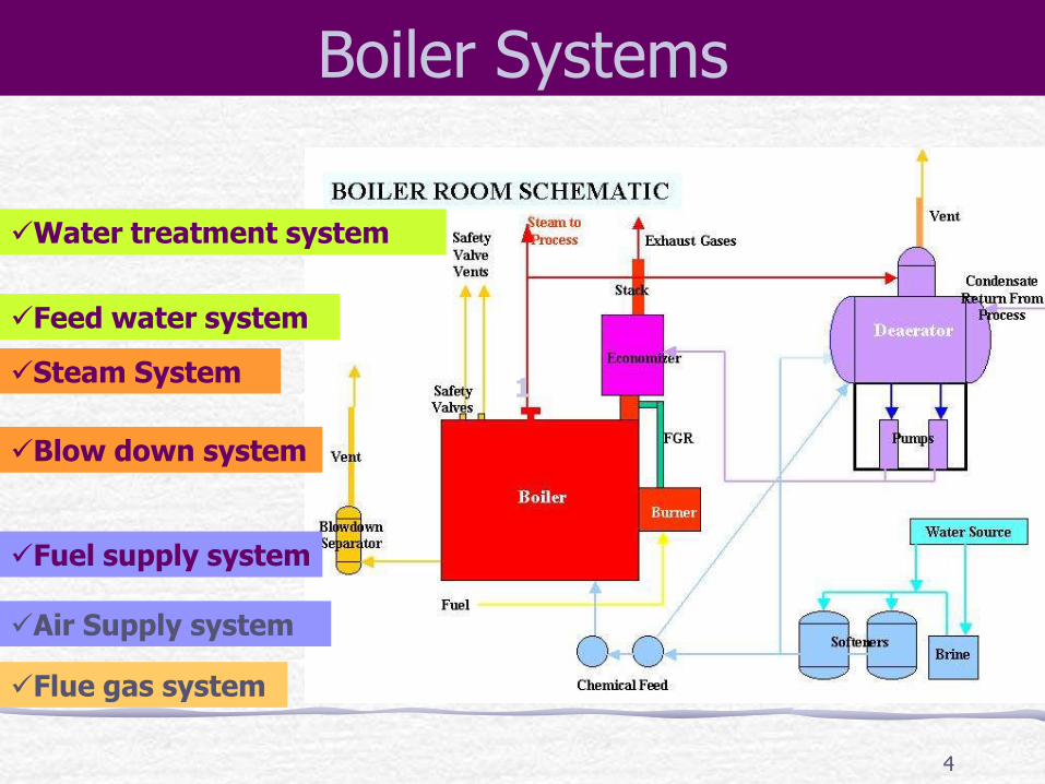
Flue gas system
Water treatment system
Feed water system
Steam System
Blow down system
Fuel supply system
Air Supply system
1
4
5
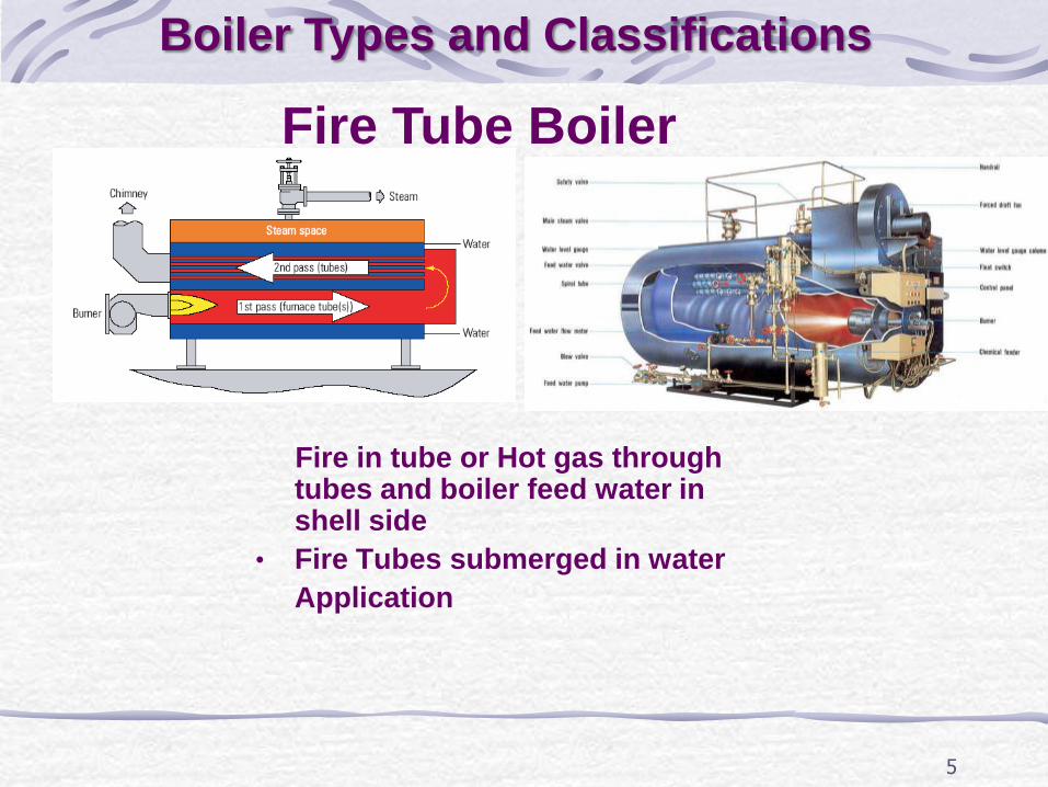
Fire in tube or Hot gas through tubes and boiler feed water in shell side
• Fire Tubes submerged in water
Application
Fire Tube Boiler
Boiler Types and Classifications
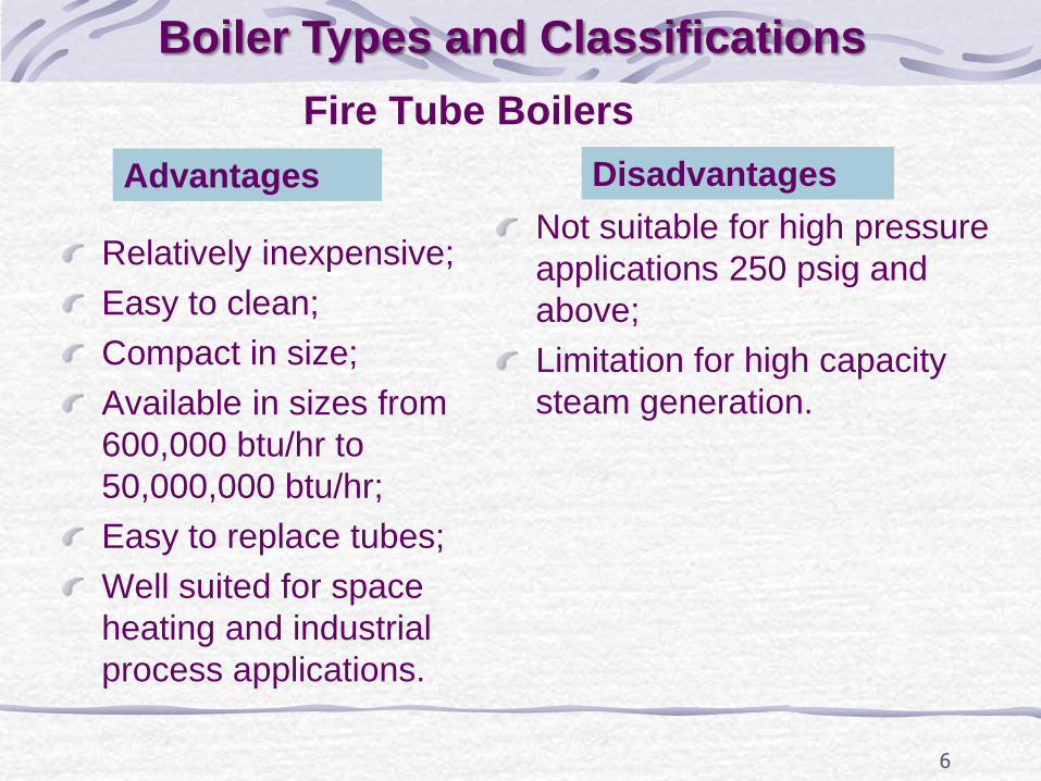
Fire Tube Boilers
Relatively inexpensive;
Easy to clean;
Compact in size;
Available in sizes from
600,000 btu/hr to
50,000,000 btu/hr;
Easy to replace tubes;
Well suited for space
heating and industrial
process applications.
Not suitable for high pressure
applications 250 psig and
above;
Limitation for high capacity
steam generation.
6
Advantages Disadvantages
Boiler Types and Classifications
7
Boiler Types and Classifications
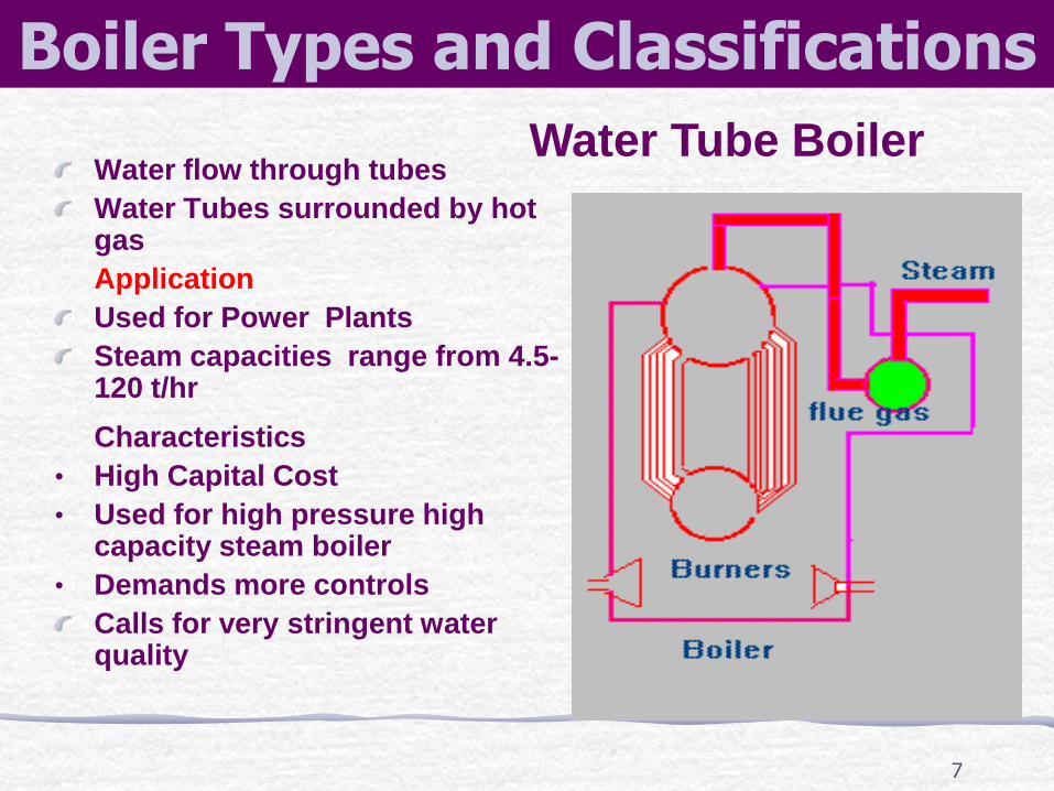
Water Tube Boiler Water flow through tubes
Water Tubes surrounded by hot gas
Application
Used for Power Plants
Steam capacities range from 4.5- 120 t/hr
Characteristics
• High Capital Cost
• Used for high pressure high capacity steam boiler
• Demands more controls
Calls for very stringent water quality
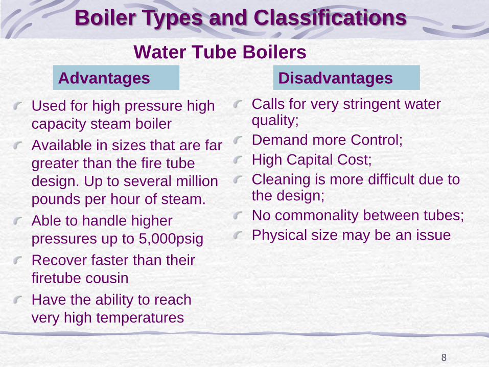
Water Tube Boilers
Used for high pressure high
capacity steam boiler
Available in sizes that are far
greater than the fire tube
design. Up to several million
pounds per hour of steam.
Able to handle higher
pressures up to 5,000psig
Recover faster than their
firetube cousin
Have the ability to reach
very high temperatures
Calls for very stringent water quality;
Demand more Control;
High Capital Cost;
Cleaning is more difficult due to the design;
No commonality between tubes;
Physical size may be an issue
8
Advantages Disadvantages
Boiler Types and Classifications
9
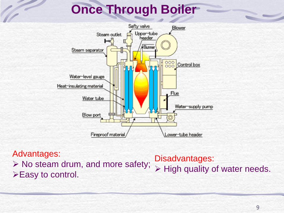
Once Through Boiler
Advantages:
No steam drum, and more safety;
Easy to control.
Disadvantages:
High quality of water needs.
Performance Evaluation of Boilers
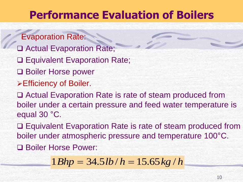
Evaporation Rate:
Actual Evaporation Rate;
Equivalent Evaporation Rate;
Boiler Horse power
Efficiency of Boiler.
Actual Evaporation Rate is rate of steam produced from
boiler under a certain pressure and feed water temperature is
equal 30 °C.
Equivalent Evaporation Rate is rate of steam produced from
boiler under atmospheric pressure and temperature 100°C.
Boiler Horse Power:
1 34.5 / 15.65 /Bhp lb h kg h
10
11
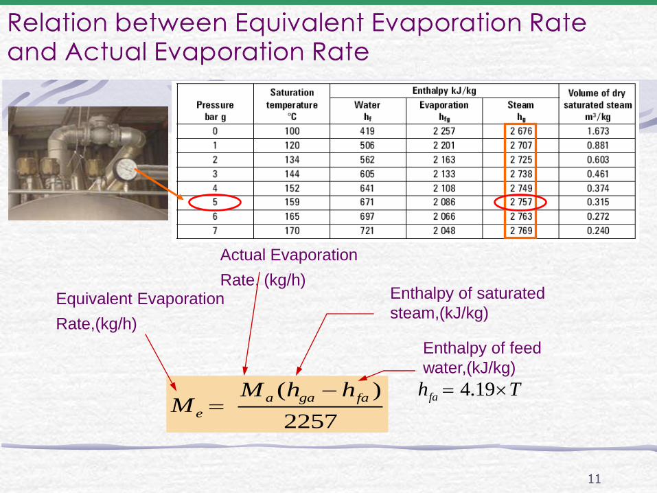
Relation between Equivalent Evaporation Rate and Actual Evaporation Rate
( )
2257
a ga fa
e
M h hM
Equivalent Evaporation
Rate,(kg/h)
Actual Evaporation
Rate, (kg/h)
Enthalpy of feed
water,(kJ/kg)
4.19fah T
Enthalpy of saturated
steam,(kJ/kg)
12
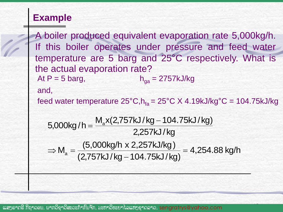
A boiler produced equivalent evaporation rate 5,000kg/h.
If this boiler operates under pressure and feed water
temperature are 5 barg and 25°C respectively. What is the actual evaporation rate? At P = 5 barg, hga = 2757kJ/kg and,
feed water temperature 25°C,hfa = 25°C X 4.19kJ/kg°C = 104.75kJ/kg
Example
ແສງຣາຕຣ ີກິຖາວອນ, ພາກວິຊາວສິະວະກ າກົນຈັກ, ມະຫາວິທະຍາໄລແຫງ່ຊາດລາວ, [email protected]
kg/h 4,254.88 )kg/kJ75.104kg/kJ757,2(
)2,257kJ/kg x (5,000kg/h M
kg/kJ257,2
)kg/kJ75.104kg/kJ757,2(xMh/kg000,5
a
a
13
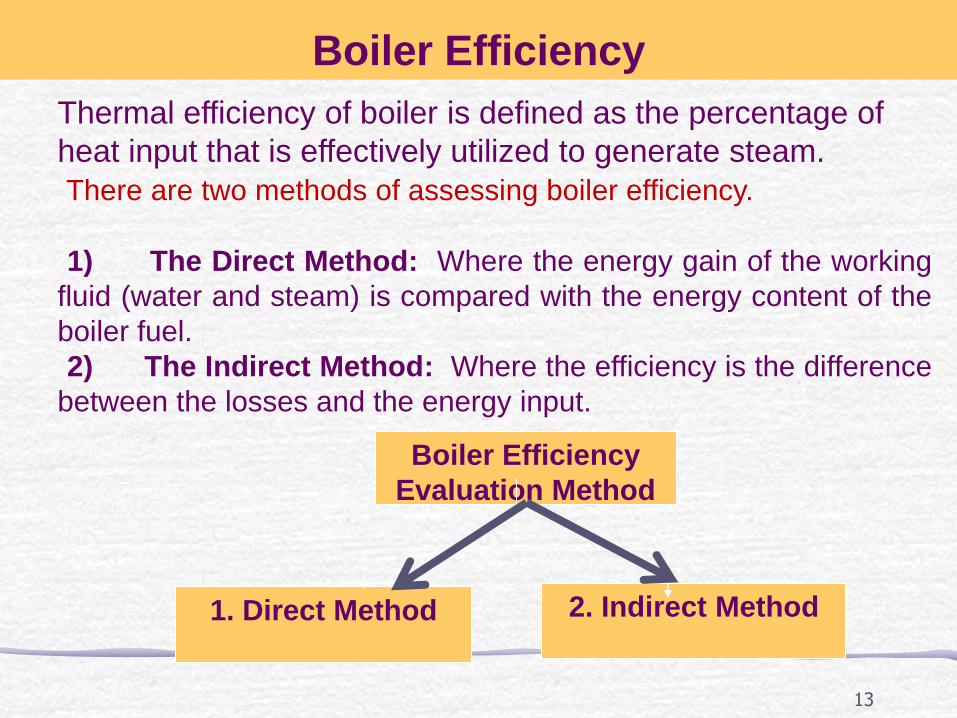
Boiler Efficiency
Thermal efficiency of boiler is defined as the percentage of
heat input that is effectively utilized to generate steam.
There are two methods of assessing boiler efficiency.
1) The Direct Method: Where the energy gain of the working
fluid (water and steam) is compared with the energy content of the
boiler fuel.
2) The Indirect Method: Where the efficiency is the difference
between the losses and the energy input.
Boiler Efficiency
Evaluation Method
1. Direct Method
2. Indirect Method
14
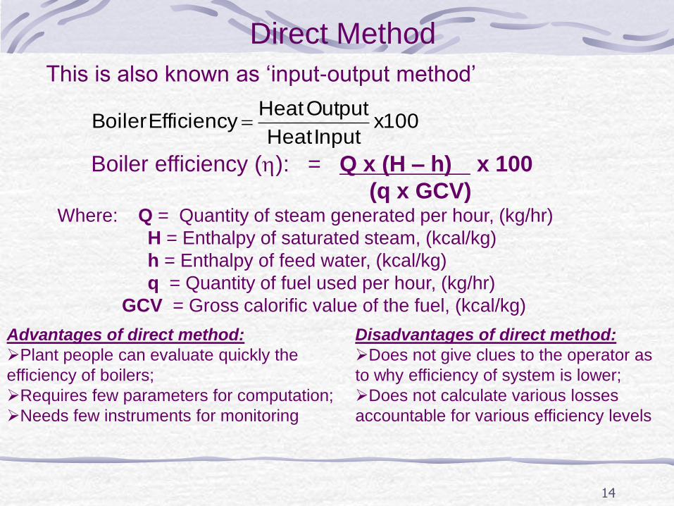
Direct Method
This is also known as ‘input-output method’
100x
Input Heat
Output Heat Efficiency Boiler
Boiler efficiency (): = Q x (H – h) x 100
(q x GCV) Where: Q = Quantity of steam generated per hour, (kg/hr)
H = Enthalpy of saturated steam, (kcal/kg)
h = Enthalpy of feed water, (kcal/kg)
q = Quantity of fuel used per hour, (kg/hr)
GCV = Gross calorific value of the fuel, (kcal/kg)
Advantages of direct method:
Plant people can evaluate quickly the
efficiency of boilers;
Requires few parameters for computation;
Needs few instruments for monitoring
Disadvantages of direct method:
Does not give clues to the operator as
to why efficiency of system is lower;
Does not calculate various losses
accountable for various efficiency levels

Example:
Type of boiler: Coal fired Boiler
Heat input data
Qty of oil consumed : 2.0 TPH
GCV of oil : 10,200 kCal/kg
Heat output data
• Qty of steam gen : 24 TPH
• Steam pr/temp:10 kg/cm2(g)/1800C
• Enthalpy of steam(sat) at 10 kg/cm2(g) pressure: 665 kCal/kg
Feed water temperature : 850 C
Enthalpy of feed water : 85 kCal/kg
Find out the Find efficiency ?
Find out the Evaporation Ratio?
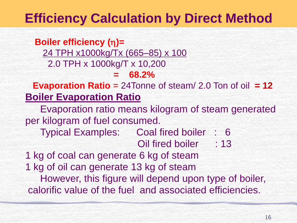
Efficiency Calculation by Direct Method
15
16
Boiler efficiency ()=
24 TPH x1000kg/Tx (665–85) x 100
2.0 TPH x 1000kg/T x 10,200
= 68.2%
Evaporation Ratio = 24Tonne of steam/ 2.0 Ton of oil = 12
Efficiency Calculation by Direct Method
Boiler Evaporation Ratio Evaporation ratio means kilogram of steam generated per kilogram of fuel consumed. Typical Examples: Coal fired boiler : 6 Oil fired boiler : 13 1 kg of coal can generate 6 kg of steam 1 kg of oil can generate 13 kg of steam However, this figure will depend upon type of boiler, calorific value of the fuel and associated efficiencies.

17
Measurement of fuel consumption rate
Fuel Tank
Fuel return pipe
Fuel Pump Fuel Oil Heater
Fuel Daily Tank
M
off
on
( )100%
( )
s g f
B
f
m h h
m HHV
Fuel consumption rate, (kg/h)
Electrode
18
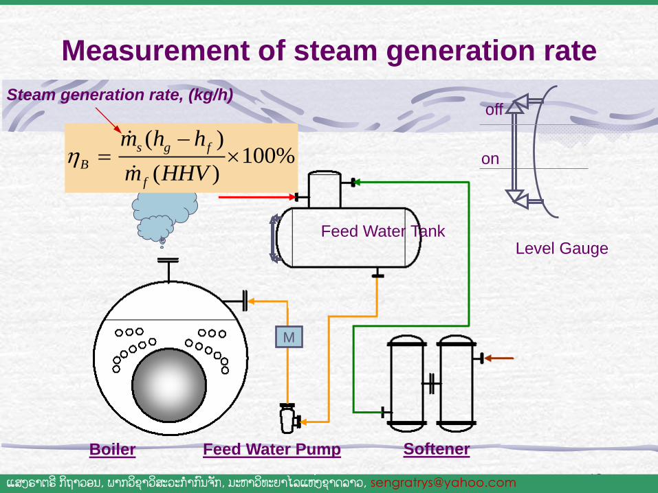
Measurement of steam generation rate
Level Gauge Feed Water Tank
Boiler Softener
ນ າ້ Condensate
Feed Water Pump
M
( )100%
( )
s g f
B
f
m h h
m HHV
Steam generation rate, (kg/h) off
on
ແສງຣາຕຣ ີກິຖາວອນ, ພາກວິຊາວສິະວະກ າກົນຈັກ, ມະຫາວິທະຍາໄລແຫງ່ຊາດລາວ, [email protected]
19
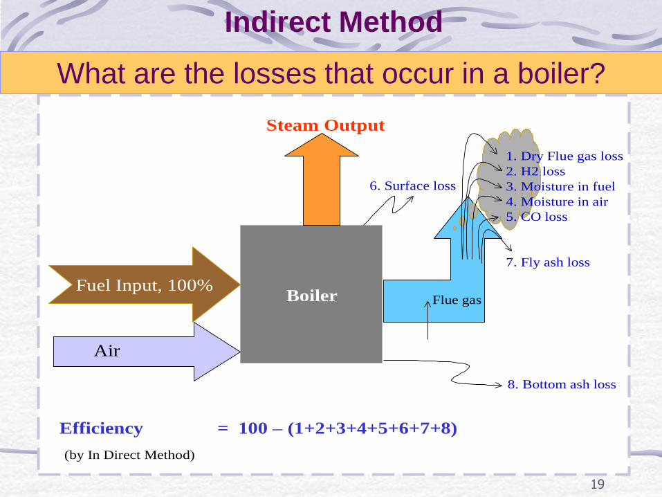
Boiler Flue gas
Steam Output
Efficiency = 100 – (1+2+3+4+5+6+7+8)
(by In Direct Method)
Air
Fuel Input, 100%
1. Dry Flue gas loss
2. H2 loss
3. Moisture in fuel
4. Moisture in air
5. CO loss
7. Fly ash loss
6. Surface loss
8. Bottom ash loss
What are the losses that occur in a boiler?
Indirect Method
20
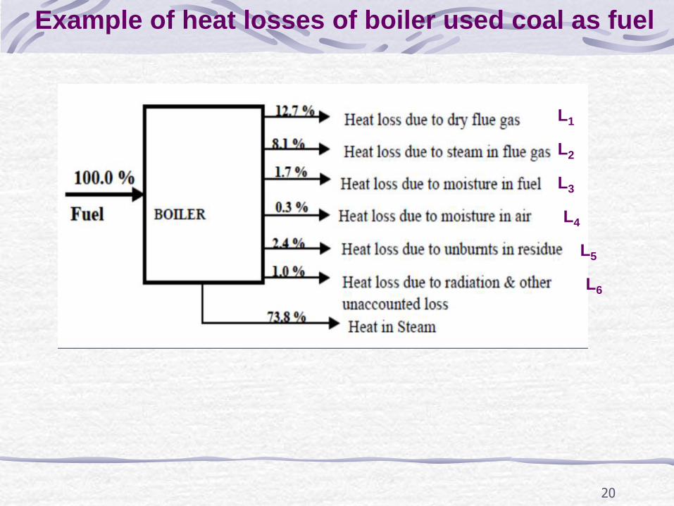
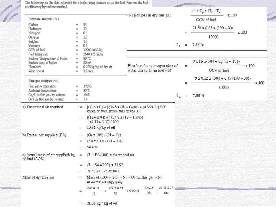
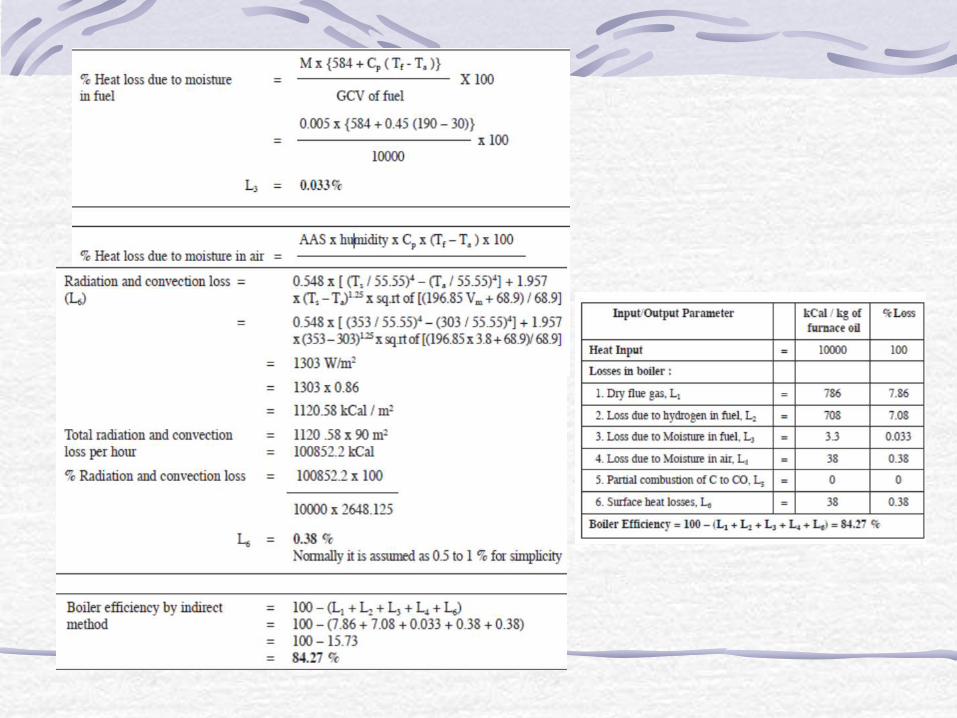
Example of heat losses of boiler used coal as fuel
L1
L2
L3
L4
L5
L6
21
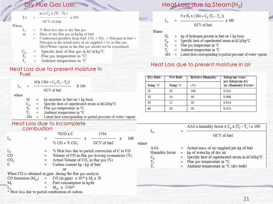
Heat Loss due to present moisture in Fuel
Heat Loss due to present moisture in air
Heat Loss due to incomplete combustion
Dry Flue Gas Loss:
Heat Loss due to Steam(H2)
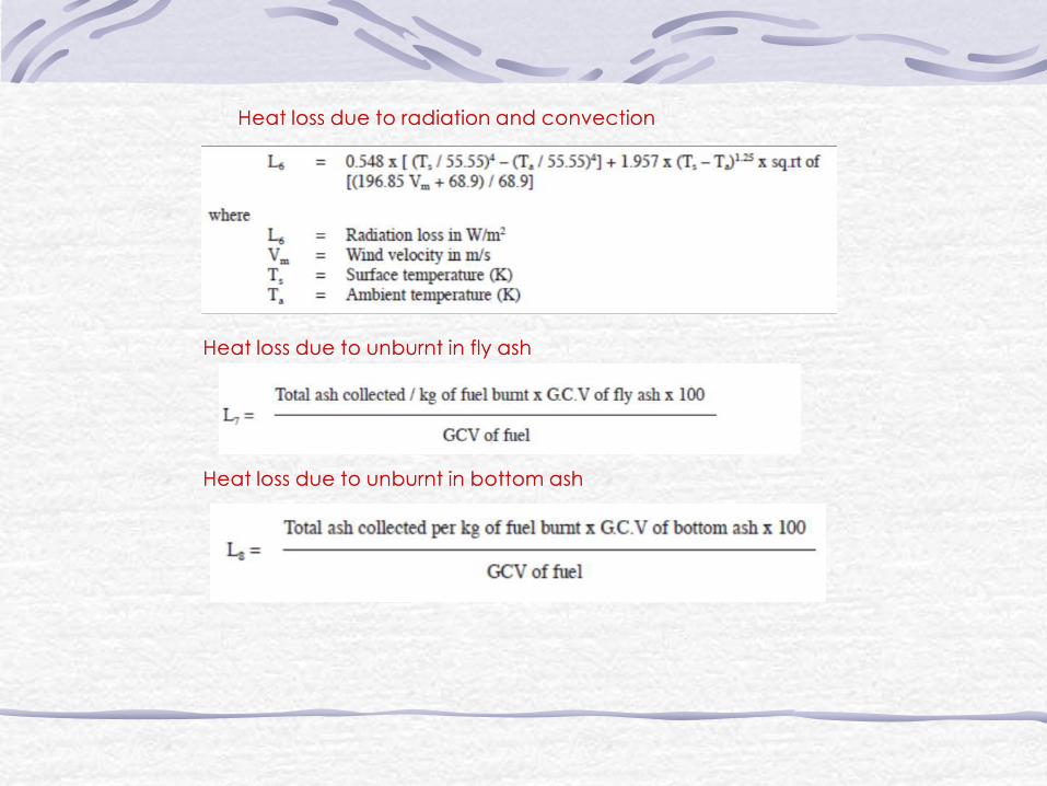
Heat loss due to radiation and convection
Heat loss due to unburnt in fly ash
Heat loss due to unburnt in bottom ash
25
Boiler Blowdown
When water is boiled and steam is generated, any dissolved solids contained in the water remain in the boiler. If more solids are put in with the feed water, they will concentrate and may eventually reach a level where their solubility in the water is exceeded and they deposit from the solution. Above a certain level of concentration, these solids encourage foaming and cause carryover of water into the steam. The deposits also lead to scale formation inside the boiler, resulting in localized overheating and finally causing boiler tube failure.

Energy Conservation Opportunities
in Boilers
27
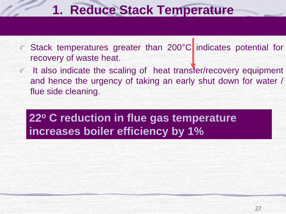
1. Reduce Stack Temperature
Stack temperatures greater than 200°C indicates potential for
recovery of waste heat.
It also indicate the scaling of heat transfer/recovery equipment
and hence the urgency of taking an early shut down for water /
flue side cleaning.
22o C reduction in flue gas temperature
increases boiler efficiency by 1%
28
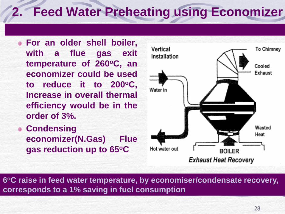
2. Feed Water Preheating using Economizer
For an older shell boiler,
with a flue gas exit
temperature of 260oC, an
economizer could be used
to reduce it to 200oC,
Increase in overall thermal
efficiency would be in the
order of 3%.
Condensing
economizer(N.Gas) Flue
gas reduction up to 65oC
6oC raise in feed water temperature, by economiser/condensate recovery,
corresponds to a 1% saving in fuel consumption

29
3. Combustion Air Preheating
Combustion air preheating is an
alternative to feed water heating.
In order to improve thermal efficiency
by 1%, the combustion air temperature
must be raised by 20 oC.
30
4. Incomplete Combustion
(c c c c c + co co co co) Incomplete combustion can arise from a shortage of air or surplus of fuel or poor distribution of fuel.
In the case of oil and gas fired systems, CO or smoke with normal or high excess air indicates burner system problems.
Example: Poor mixing of fuel and air at the burner. Poor oil fires can result from improper viscosity, worn tips, carbonization on tips and deterioration of diffusers.
With coal firing: Loss occurs as grit carry-over or carbon-in-ash (2% loss).
Example :In chain grate stokers, large lumps will not burn out completely, while small pieces and fines may block the air passage, thus causing poor air distribution.
Increase in the fines in pulverized coal also increases carbon loss.
31
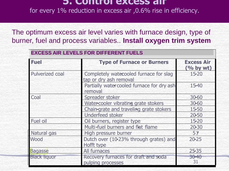
5. Control excess air for every 1% reduction in excess air ,0.6% rise in efficiency.
The optimum excess air level varies with furnace design, type of
burner, fuel and process variables.. Install oxygen trim system
EXCESS AIR LEVELS FOR DIFFERENT FUELS
Fuel Type of Furnace or Burners Excess Air (% by wt)
Completely water - cooled furnace for slag tap or dry ash removal
15 - 20 Pulverized coal
Partially water - cooled furnace for dry ash removal
15 - 40
Spreader stoker 30 - 60 Water - cooler vibrating - grate stokers 30 - 60 Chain - grate and traveling - grate stokers 15 - 50
Coal
Underfeed stoker 20 - 50 Fuel oil Oil burners, register type 15 - 20 Multi - fuel burners and flat - flame 20 - 30 Natural gas High pressure burner 5 - 7 Wood Dutch over (10 - 23% through grates) and
Hofft type 20 - 25
Bagasse All furnaces 25 - 35 Black liquor Recovery furnaces for draft and soda -
pulping processes 30 - 40
32
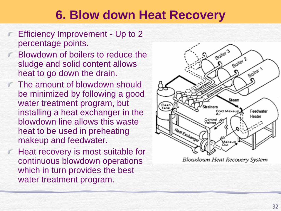
6. Blow down Heat Recovery
Efficiency Improvement - Up to 2 percentage points.
Blowdown of boilers to reduce the sludge and solid content allows heat to go down the drain.
The amount of blowdown should be minimized by following a good water treatment program, but installing a heat exchanger in the blowdown line allows this waste heat to be used in preheating makeup and feedwater.
Heat recovery is most suitable for continuous blowdown operations which in turn provides the best water treatment program.
33
8.Reduction of Scaling and Soot Losses
In oil and coal-fired boilers, soot buildup on tubes acts as an insulator against heat transfer. Any such deposits should be removed on a regular basis. Elevated stack temperatures may indicate excessive soot buildup. Also same result will occur due to scaling on the water side.
High exit gas temperatures at normal excess air indicate poor heat transfer performance. This condition can result from a gradual build-up of gas-side or waterside deposits. Waterside deposits require a review of water treatment procedures and tube cleaning to remove deposits.
Stack temperature should be checked and recorded regularly as an indicator of soot deposits. When the flue gas temperature rises about 20oC above the temperature for a newly cleaned boiler, it is time to remove the soot deposits
34
9. Reduction of Boiler Steam Pressure
Lower steam pressure gives a lower saturated steam temperature and without stack heat recovery, a similar reduction in the temperature of the flue gas temperature results. Potential 1 to 2% improvement.
Steam is generated at pressures normally dictated by the highest pressure / temperature requirements for a particular process. In some cases, the process does not operate all the time, and there are periods when the boiler pressure could be reduced.
Adverse effects, such as an increase in water carryover from the boiler owing to pressure reduction, may negate any potential saving.
Pressure should be reduced in stages, and no more than a 20 percent reduction should be considered.
35
10. Variable Speed Control for Fans, Blowers
and Pumps
Generally, combustion air control is effected by throttling
dampers fitted at forced and induced draft fans. Though
dampers are simple means of control, they lack accuracy,
giving poor control characteristics at the top and bottom of
the operating range.
If the load characteristic of the boiler is variable, the
possibility of replacing the dampers by a VSD should be
evaluated.

36
11. Effect of Boiler Loading on Efficiency
As the load falls, so does the value of the mass flow rate of
the flue gases through the tubes. This reduction in flow rate
for the same heat transfer area, reduced the exit flue gas
temperatures by a small extent, reducing the sensible heat
loss.
Below half load, most combustion appliances need more
excess air to burn the fuel completely and increases the
sensible heat loss.
Operation of boiler below 25% should be avoided
Optimum efficiency occurs at 65-85% of full loads

37
12. Boiler Replacement
if the existing boiler is :
Old and inefficient, not capable of firing cheaper
substitution fuel, over or under-sized for present
requirements, not designed for ideal loading conditions
replacement option should be explored.
• Since boiler plants traditionally have a useful life of well over
25 years, replacement must be carefully studied.
38
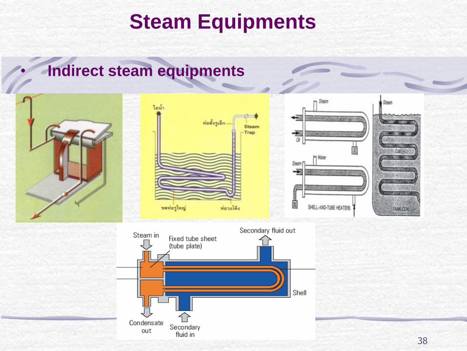
Steam Equipments
• Indirect steam equipments
39
Introduction
Transport and provision of energy:
Highest specific heat and latent heat;
Highest heat transfer coefficient.
Benefits:
Efficient and economic to generate;
Easy to distribute and control;
Cheap and Inert;
Easily transferred to the process;
Steam plant easy to manage;
Flexible;
Alternatives are hot water and oils
Why do we use steam?
Energy Efficiency in Steam System
40
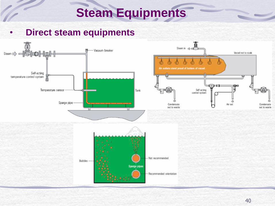
• Direct steam equipments
Steam Equipments
41
Introduction
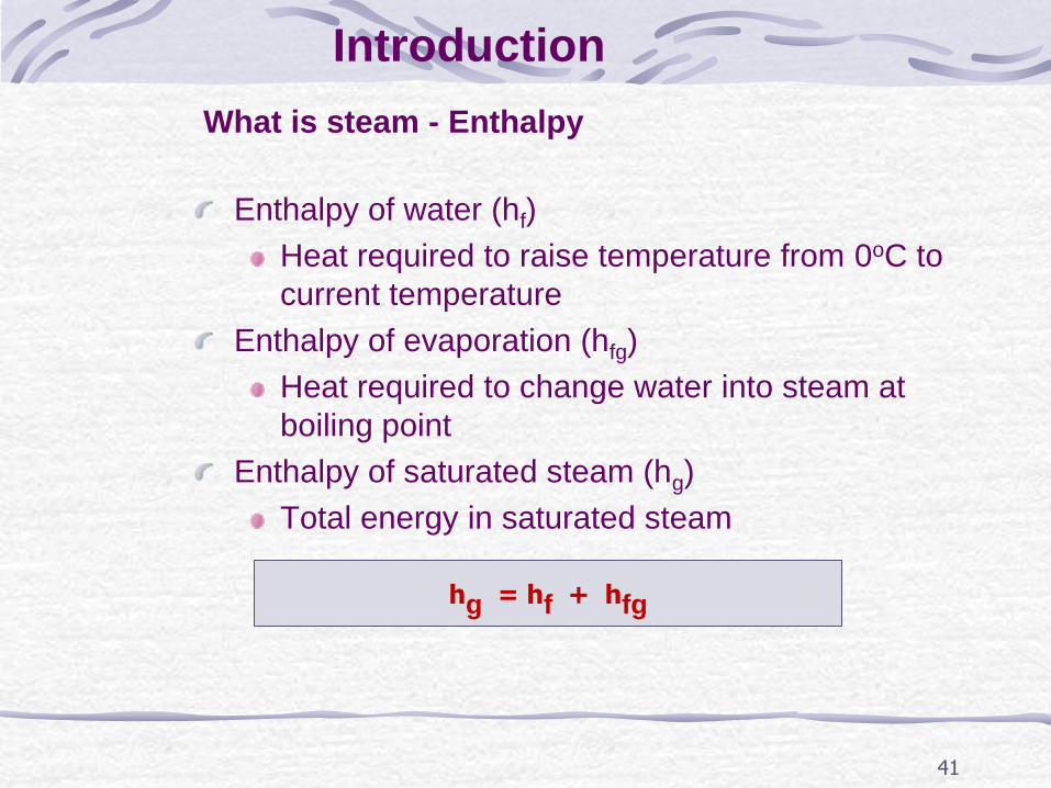
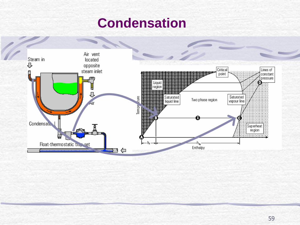
Enthalpy of water (hf)
Heat required to raise temperature from 0oC to
current temperature
Enthalpy of evaporation (hfg)
Heat required to change water into steam at
boiling point
Enthalpy of saturated steam (hg)
Total energy in saturated steam
What is steam - Enthalpy
hg = hf + hfg
42
Introduction(Cont...)
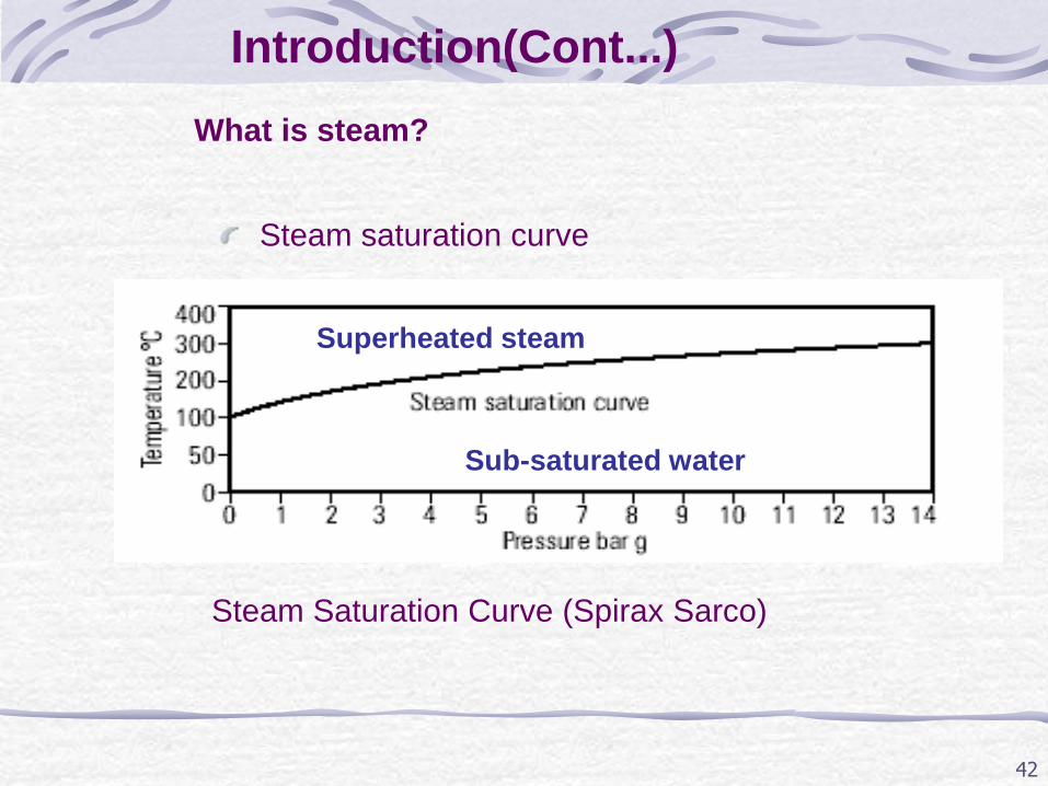
Steam saturation curve
What is steam?
Steam Saturation Curve (Spirax Sarco)
Superheated steam
Sub-saturated water
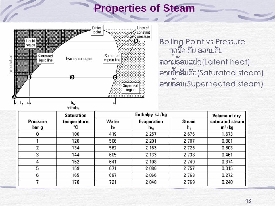
43
Boiling Point vs Pressure ຈຸດຟດົ ກັບ ຄວາມດັນ
ຄວາມຮອ້ນແຝງ(Latent heat) ອາຍນ ້າອີ່ມຕົວ(Saturated steam) ອາຍຮ້ອນ(Superheated steam)
Properties of Steam
The Working Pressure
The distribution pressure of steam is influenced by a number
of factors, but is limited by:
The maximum safe working pressure of the boiler; The minimum pressure required at the plant.
As steam passes through the distribution pipework, it will
inevitably lose pressure due to:
Frictional resistance within the pipework;
Condensation within the pipework as heat is transferred to
the environment.
Therefore allowance should be made for this pressure loss when deciding upon the initial distribution pressure.
44
45
Steam Quality
Steam should be available at the point of use:
• In the correct quantity;
• At the correct temperature and pressure;
• Free from air and incondensable gases;
• Dry and Clean.
46
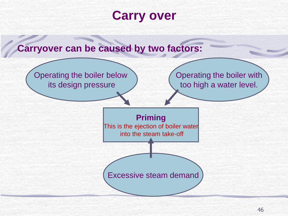
Carry over
Carryover can be caused by two factors:
Priming This is the ejection of boiler water
into the steam take-off
Operating the boiler with
too high a water level.
Operating the boiler below
its design pressure
Excessive steam demand
47
Carry over
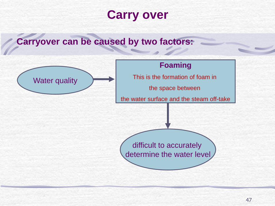
Carryover can be caused by two factors:
Foaming
This is the formation of foam in
the space between
the water surface and the steam off-take
Water quality
difficult to accurately
determine the water level
48
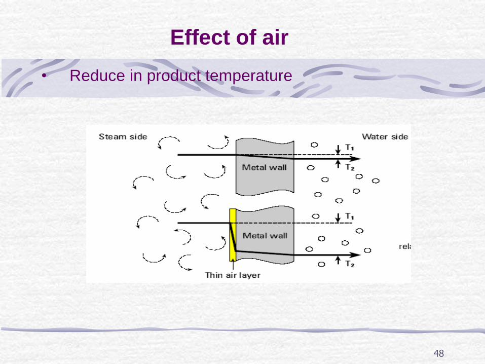
Effect of air
• Reduce in product temperature
49
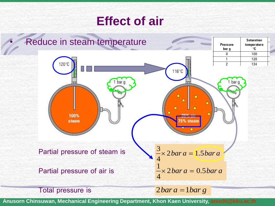
Effect of air
Anusorn Chinsuwan, Mechanical Engineering Department, Khon Kaen University, [email protected]
Partial pressure of steam is
Partial pressure of air is
Total pressure is
32 1.5
4bar a bar a
12 0.5
4bar a bar a
2 1bar a bar g
• Reduce in steam temperature
50
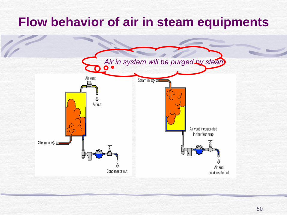
Flow behavior of air in steam equipments
Air in system will be purged by steam
51
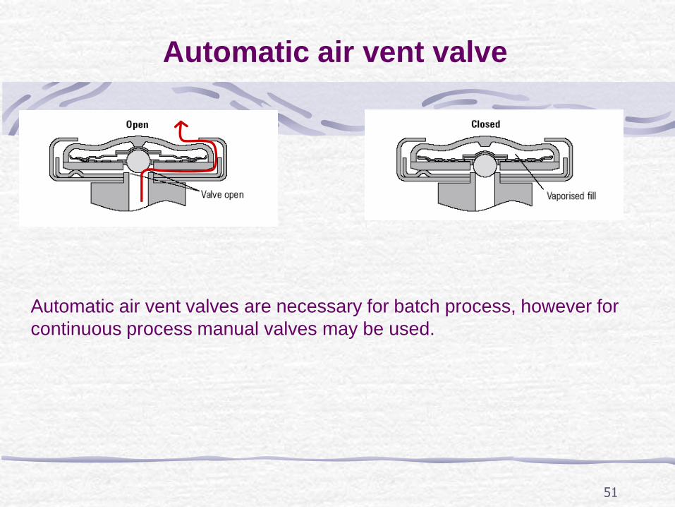
Automatic air vent valve
Automatic air vent valves are necessary for batch process, however for
continuous process manual valves may be used.
52
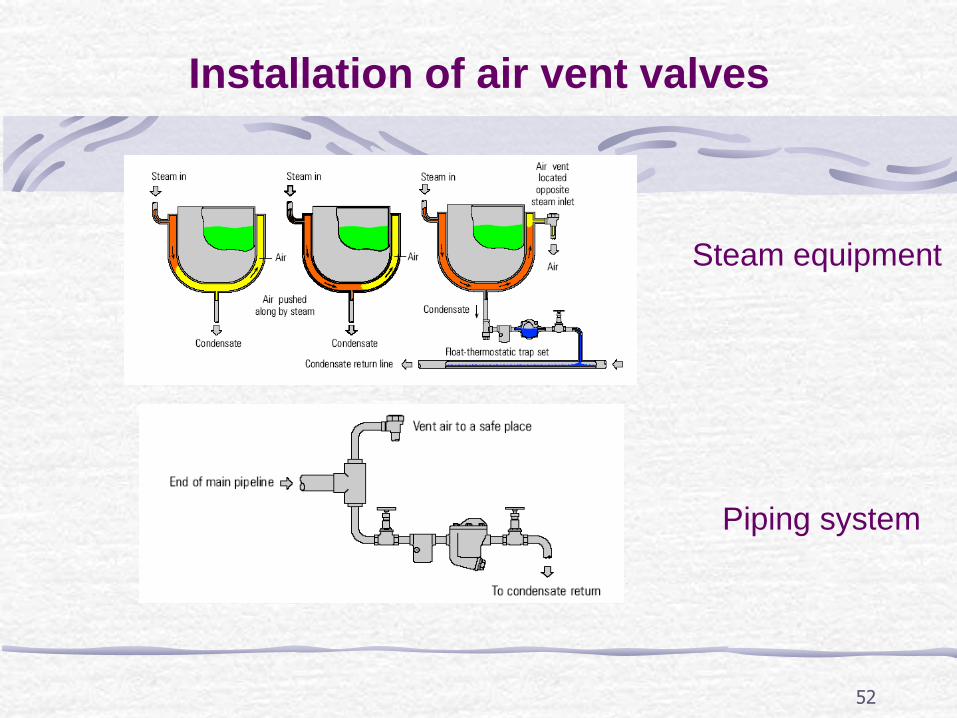
Installation of air vent valves
Steam equipment
Piping system
53
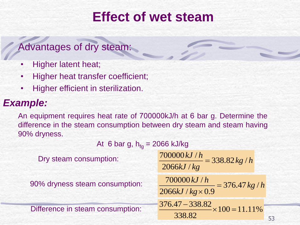
Effect of wet steam
Advantages of dry steam:
• Higher latent heat;
• Higher heat transfer coefficient;
• Higher efficient in sterilization.
An equipment requires heat rate of 700000kJ/h at 6 bar g. Determine the
difference in the steam consumption between dry steam and steam having
90% dryness.
Example:
Dry steam consumption:
90% dryness steam consumption:
Difference in steam consumption:
700000 /376.47 /
2066 / 0.9
kJ hkg h
kJ kg
376.47 338.82100 11.11%
338.82
At 6 bar g, hfg = 2066 kJ/kg
700000 /338.82 /
2066 /
kJ hkg h
kJ kg
54
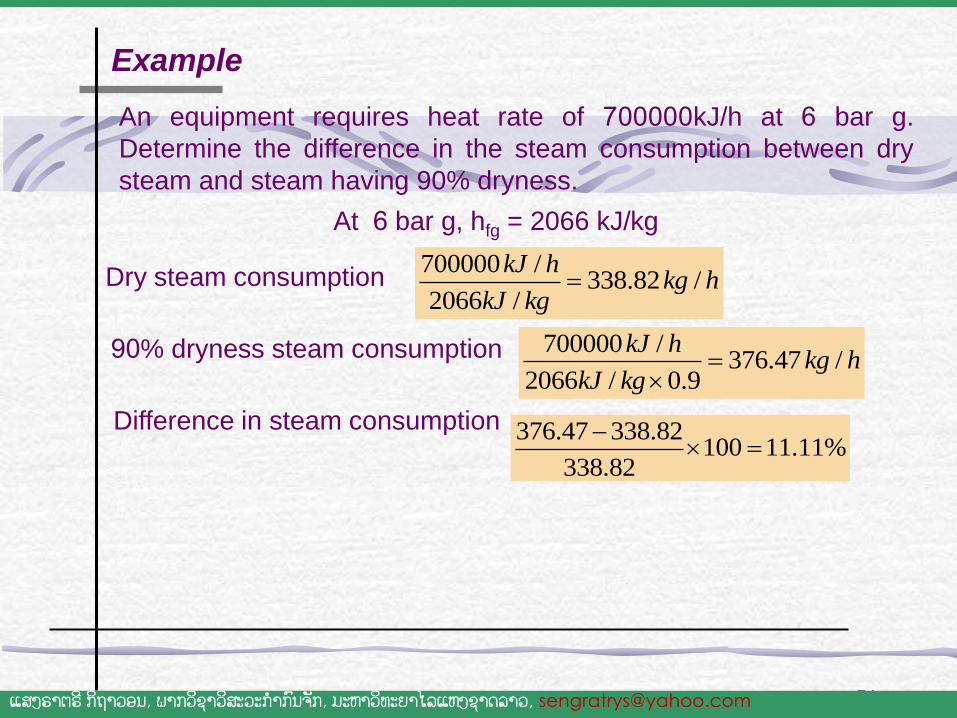
An equipment requires heat rate of 700000kJ/h at 6 bar g.
Determine the difference in the steam consumption between dry
steam and steam having 90% dryness.
Dry steam consumption
Example
At 6 bar g, hfg = 2066 kJ/kg
700000 /338.82 /
2066 /
kJ hkg h
kJ kg
90% dryness steam consumption 700000 /376.47 /
2066 / 0.9
kJ hkg h
kJ kg
376.47 338.82100 11.11%
338.82
Difference in steam consumption
ແສງຣາຕຣ ີກິຖາວອນ, ພາກວິຊາວສິະວະກ າກົນຈັກ, ມະຫາວິທະຍາໄລແຫງ່ຊາດລາວ, [email protected]
55
How to improve steam dryness
• Steam Separator
• Pressure Reducing Valve
• Steam Header
• Operate boilers at recommend operating conditions
• Feed water treatment
56
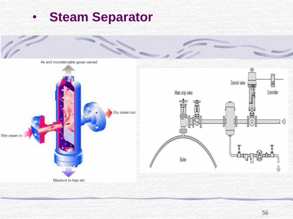
• Steam Separator
57
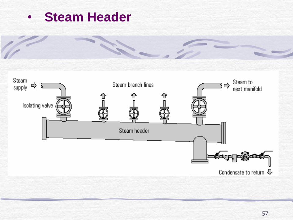
• Steam Header
58
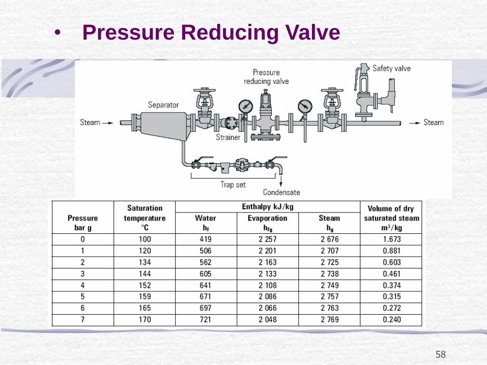
• Pressure Reducing Valve
59
Condensation
60
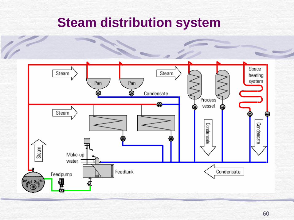
Steam distribution system
61
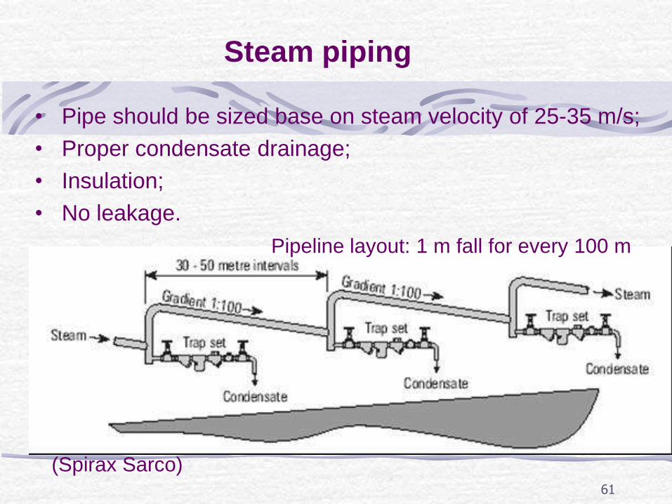
Steam piping
• Pipe should be sized base on steam velocity of 25-35 m/s;
• Proper condensate drainage;
• Insulation;
• No leakage.
Pipeline layout: 1 m fall for every 100 m
(Spirax Sarco)
62
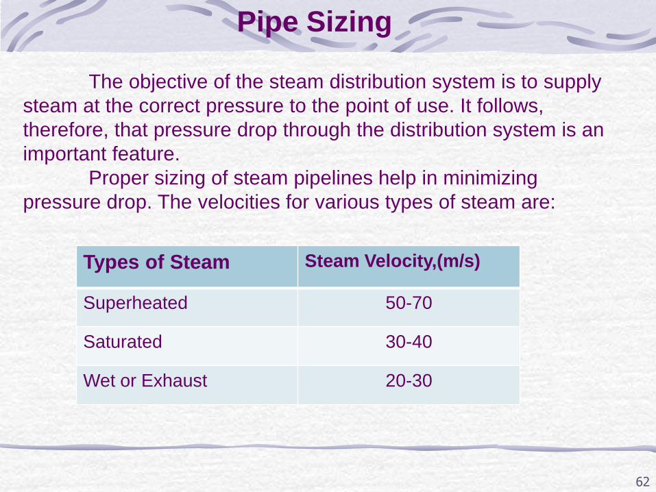
Pipe Sizing
The objective of the steam distribution system is to supply
steam at the correct pressure to the point of use. It follows,
therefore, that pressure drop through the distribution system is an
important feature.
Proper sizing of steam pipelines help in minimizing
pressure drop. The velocities for various types of steam are:
Types of Steam Steam Velocity,(m/s)
Superheated 50-70
Saturated 30-40
Wet or Exhaust 20-30
63
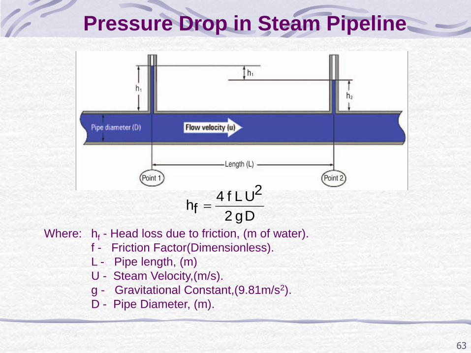
Pressure Drop in Steam Pipeline
D g 2
2U L f 4 fh
Where: hf - Head loss due to friction, (m of water).
f - Friction Factor(Dimensionless).
L - Pipe length, (m)
U - Steam Velocity,(m/s).
g - Gravitational Constant,(9.81m/s2).
D - Pipe Diameter, (m).
Example:
64
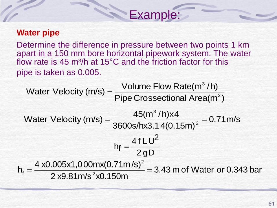
Water pipe Determine the difference in pressure between two points 1 km apart in a 150 mm bore horizontal pipework system. The water flow rate is 45 m³/h at 15°C and the friction factor for this pipe is taken as 0.005.
) Area(mnalCrossectio Pipe
)h/Rate(mFlow Volume (m/s) Velocity Water
2
3
m/s 0.71 4(0.15m)600s/hx3.13
4x)h/45(m (m/s) Velocity Water
2
3
D g 2
2U L f 4 fh
bar 0.343 or Water of m 3.43 x0.150mx9.81m/s 2
/s)00mx(0.71mx0.005x1,0 4 h
2
2
f
65
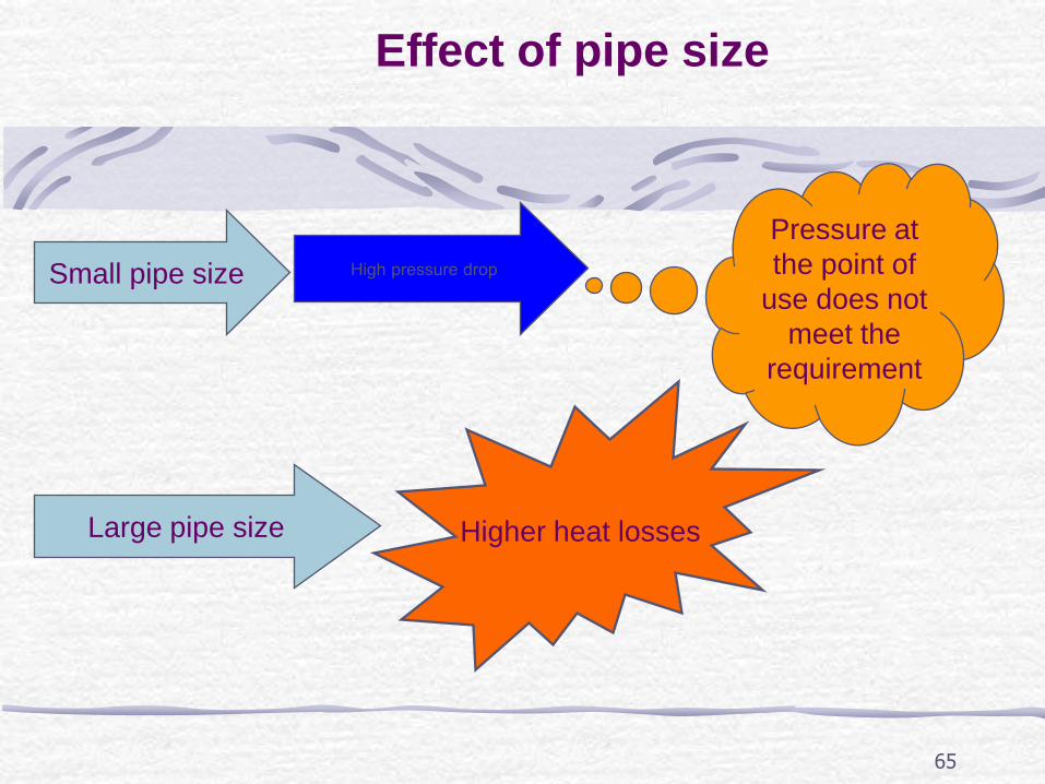
Effect of pipe size
Small pipe size High pressure drop
Pressure at
the point of
use does not
meet the
requirement
Large pipe size Higher heat losses
66
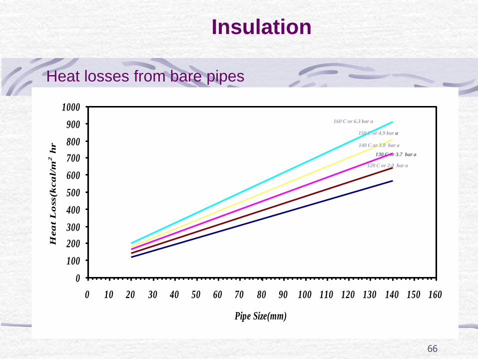
Insulation
Heat losses from bare pipes
0
100
200
300
400
500
600
700
800
900
1000
0 10 20 30 40 50 60 70 80 90 100 110 120 130 140 150 160
Pipe Size(mm)
Hea
t L
oss(k
ca
l/m
2 h
r
160 C or 6.3 bar a
150 C or 4.9 bar a
130 C or 3.7 bar a
120 C or 2.0 bar a
140 C or 3.8 bar a
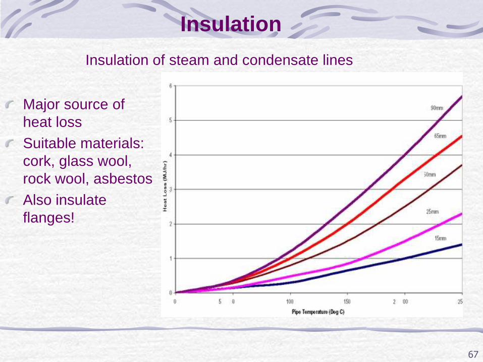
67
Major source of
heat loss
Suitable materials:
cork, glass wool,
rock wool, asbestos
Also insulate
flanges!
Insulation
Insulation of steam and condensate lines
68
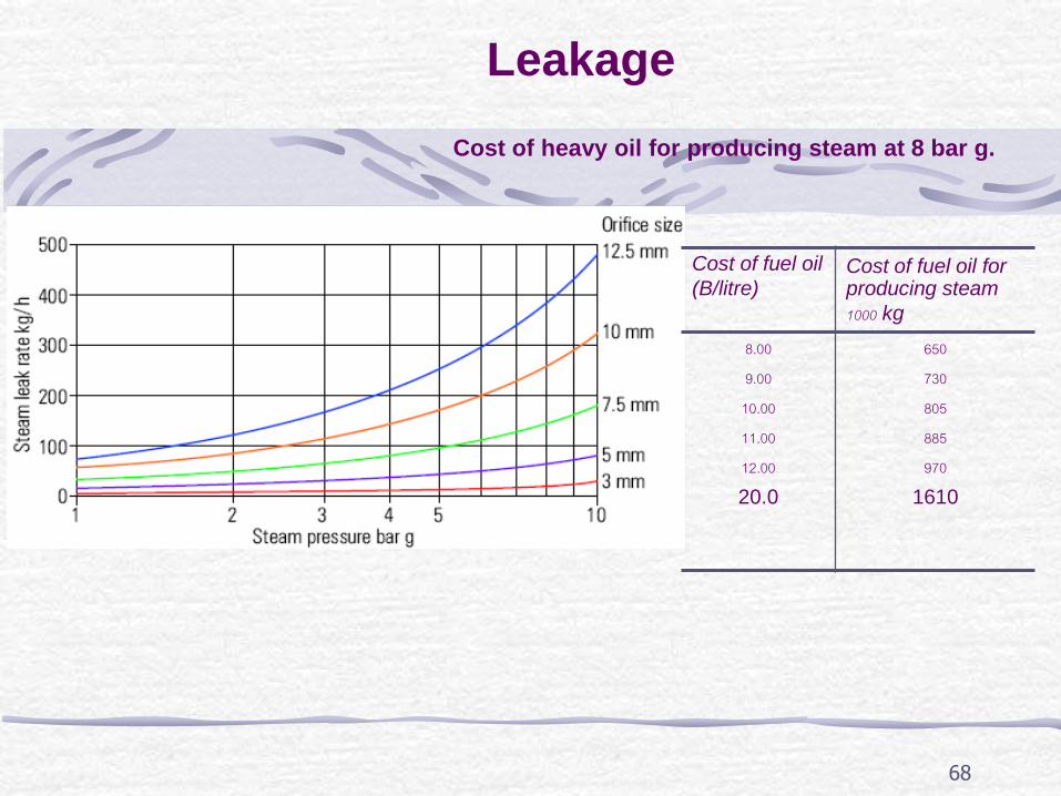
Leakage
Cost of fuel oil (B/litre)
Cost of fuel oil for producing steam 1000 kg
8.00
9.00
10.00
11.00
12.00
20.0
650
730
805
885
970
1610
Cost of heavy oil for producing steam at 8 bar g.
69
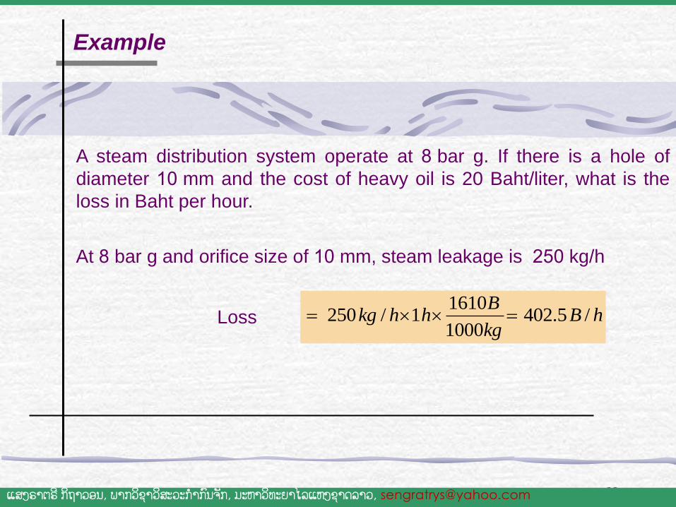
A steam distribution system operate at 8 bar g. If there is a hole of
diameter 10 mm and the cost of heavy oil is 20 Baht/liter, what is the
loss in Baht per hour.
1610250 / 1 402.5 /
1000
Bkg h h B h
kg
At 8 bar g and orifice size of 10 mm, steam leakage is 250 kg/h
Example
Loss
ແສງຣາຕຣ ີກິຖາວອນ, ພາກວິຊາວສິະວະກ າກົນຈັກ, ມະຫາວິທະຍາໄລແຫງ່ຊາດລາວ, [email protected]
70
Condensate drainage
• Steam Trap
• Drainage
– Drain from piping system
– Drain from equipments
71
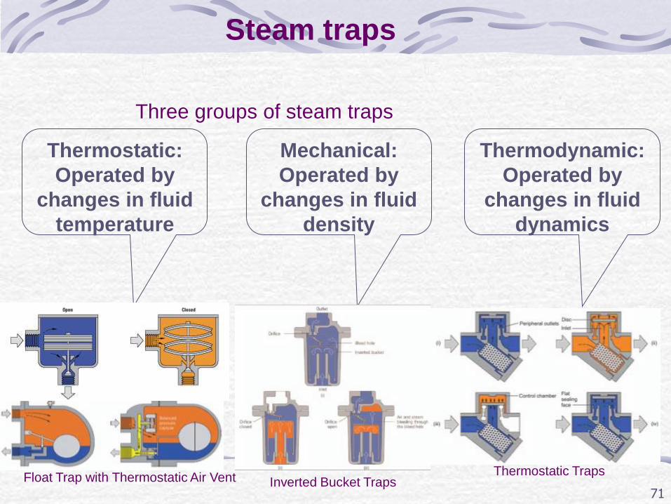
Three groups of steam traps
Steam traps
Thermostatic:
Operated by
changes in fluid
temperature
Mechanical:
Operated by
changes in fluid
density
Thermodynamic:
Operated by
changes in fluid
dynamics
Thermostatic Traps Inverted Bucket Traps Float Trap with Thermostatic Air Vent
72
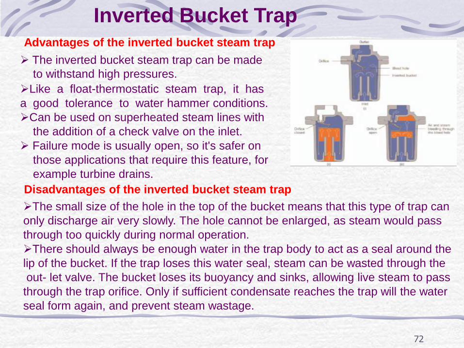
Inverted Bucket Trap
The inverted bucket steam trap can be made
to withstand high pressures. Like a float-thermostatic steam trap, it has a good tolerance to water hammer conditions. Can be used on superheated steam lines with the addition of a check valve on the inlet. Failure mode is usually open, so it's safer on those applications that require this feature, for example turbine drains.
Advantages of the inverted bucket steam trap
There should always be enough water in the trap body to act as a seal around the lip of the bucket. If the trap loses this water seal, steam can be wasted through the out- let valve. The bucket loses its buoyancy and sinks, allowing live steam to pass through the trap orifice. Only if sufficient condensate reaches the trap will the water seal form again, and prevent steam wastage.
The small size of the hole in the top of the bucket means that this type of trap can only discharge air very slowly. The hole cannot be enlarged, as steam would pass through too quickly during normal operation.
Disadvantages of the inverted bucket steam trap
73
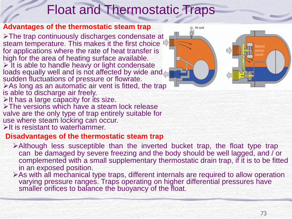
Float and Thermostatic Traps Advantages of the thermostatic steam trap
Disadvantages of the thermostatic steam trap
The trap continuously discharges condensate at steam temperature. This makes it the first choice for applications where the rate of heat transfer is high for the area of heating surface available. It is able to handle heavy or light condensate loads equally well and is not affected by wide and sudden fluctuations of pressure or flowrate. As long as an automatic air vent is fitted, the trap is able to discharge air freely. It has a large capacity for its size. The versions which have a steam lock release valve are the only type of trap entirely suitable for use where steam locking can occur. It is resistant to waterhammer.
Although less susceptible than the inverted bucket trap, the float type trap can be damaged by severe freezing and the body should be well lagged, and / or complemented with a small supplementary thermostatic drain trap, if it is to be fitted in an exposed position. As with all mechanical type traps, different internals are required to allow operation varying pressure ranges. Traps operating on higher differential pressures have smaller orifices to balance the buoyancy of the float.
74
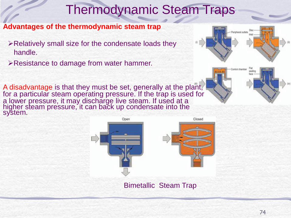
Thermodynamic Steam Traps Advantages of the thermodynamic steam trap
Relatively small size for the condensate loads they handle. Resistance to damage from water hammer.
A disadvantage is that they must be set, generally at the plant, for a particular steam operating pressure. If the trap is used for a lower pressure, it may discharge live steam. If used at a higher steam pressure, it can back up condensate into the system.
Bimetallic Steam Trap
75
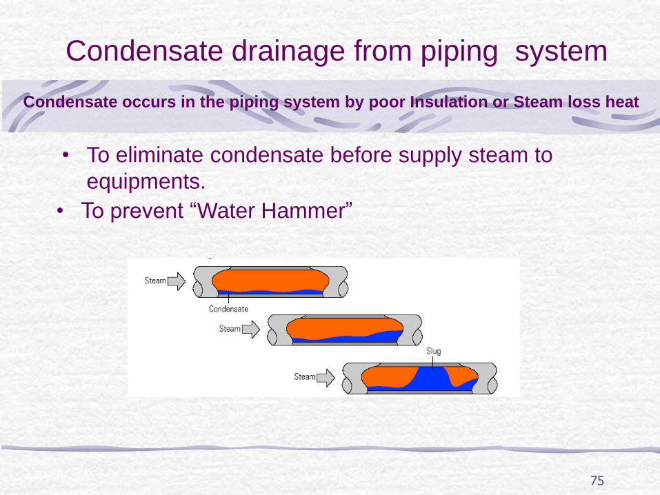
Condensate drainage from piping system
• To eliminate condensate before supply steam to
equipments.
• To prevent “Water Hammer”
Condensate occurs in the piping system by poor Insulation or Steam loss heat
76
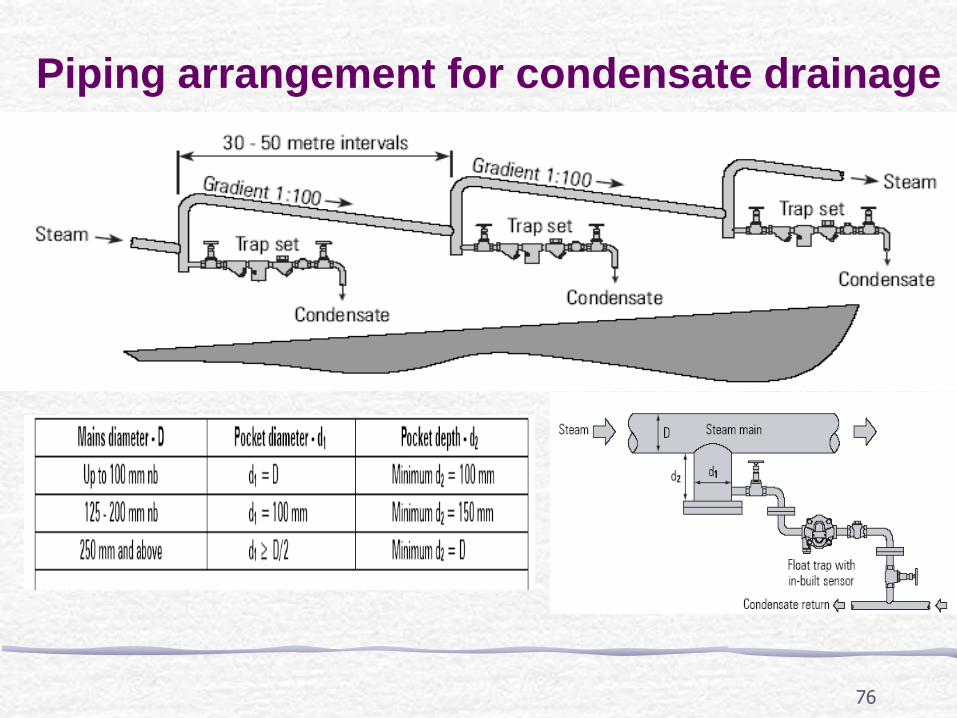
Piping arrangement for condensate drainage
77
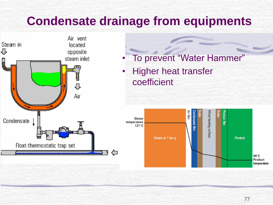
Condensate drainage from equipments
• To prevent “Water Hammer”
• Higher heat transfer
coefficient
78
Guide for proper drainage and layout of steam lines: 1. The steam mains should be run with a falling slope of not less that 125mm for every 30metres length in the direction of the steam flow. 2. Drain points should be provided at intervals of 30–45 metres along the main. 3. Drain points should also be provided at low points in the mains and where the main rises. Ideal locations are the bottom of expansion joints and before reduction and stop valves. 4. Drain points in the main lines should be through an equal tee connection only. 5. It is preferable to choose open bucket or TD traps on account of their resilience. 6. The branch lines from the mains should always be connected at the top Otherwise, the branch line itself will act as a drain for the condensate. 7. Insecure supports as well as an alteration in level can lead to formation of water pockets in steam, leading to wet steam delivery. Providing proper vertical and support hangers helps overcome such eventualities. 8. To ensure dry steam in the process equipment and in branch lines, steam separators can be installed as required. 9. Expansion loops are required to accommodate the expansion of steam lines while starting from cold.
79
Condensate recovery
• Feed to feed water tank; • Flash steam.
• High temperature • Treated water
Condensate utilization:
Advantages of condensate:
80
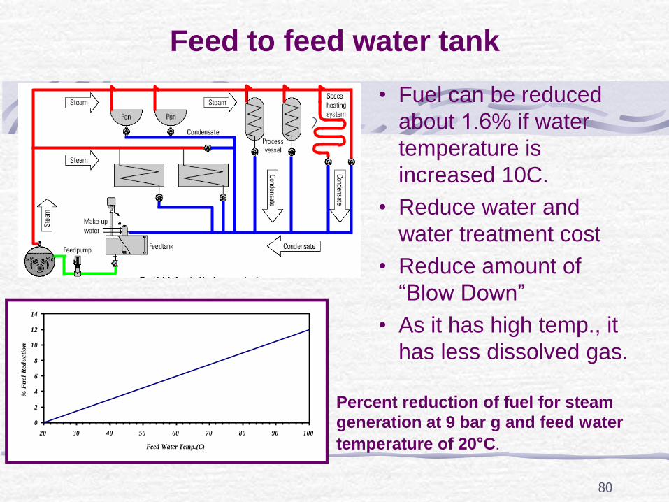
Feed to feed water tank
• Fuel can be reduced
about 1.6% if water
temperature is
increased 10C.
• Reduce water and
water treatment cost
• Reduce amount of
“Blow Down”
• As it has high temp., it
has less dissolved gas.
0
2
4
6
8
10
12
14
20 30 40 50 60 70 80 90 100
Feed Water Temp.(C)
% F
uel
Red
ucti
on
Percent reduction of fuel for steam
generation at 9 bar g and feed water
temperature of 20°C.
81
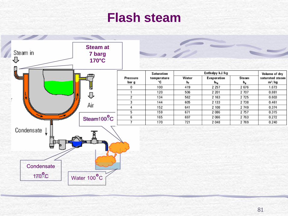
Flash steam
Condensate 170C
Steam 100C
Condensate 170°C
Steam at
7 barg
170°C
Steam100°C
Water 100°C
82
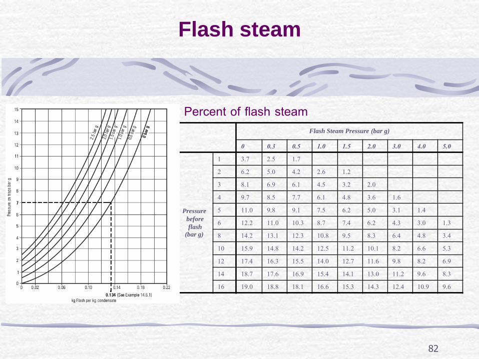
Flash steam
Flash Steam Pressure (bar g)
0 0.3 0.5 1.0 1.5 2.0 3.0 4.0 5.0
Pressure
before
flash
(bar g)
1 3.7 2.5 1.7
2 6.2 5.0 4.2 2.6 1.2
3 8.1 6.9 6.1 4.5 3.2 2.0
4 9.7 8.5 7.7 6.1 4.8 3.6 1.6
5 11.0 9.8 9.1 7.5 6.2 5.0 3.1 1.4
6 12.2 11.0 10.3 8.7 7.4 6.2 4.3 3.0 1.3
8 14.2 13.1 12.3 10.8 9.5 8.3 6.4 4.8 3.4
10 15.9 14.8 14.2 12.5 11.2 10.1 8.2 6.6 5.3
12 17.4 16.3 15.5 14.0 12.7 11.6 9.8 8.2 6.9
14 18.7 17.6 16.9 15.4 14.1 13.0 11.2 9.6 8.3
16 19.0 18.8 18.1 16.6 15.3 14.3 12.4 10.9 9.6
Percent of flash steam
83
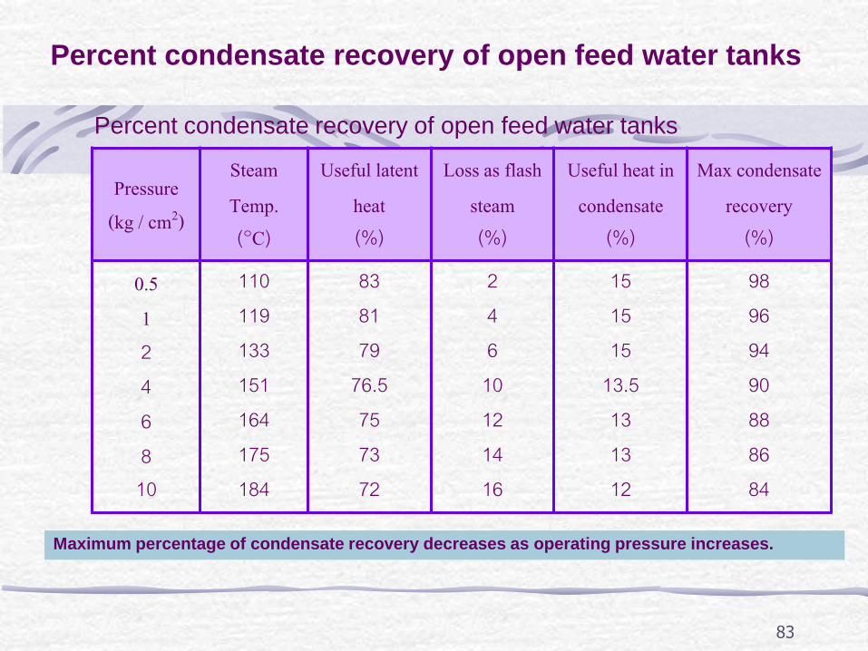
Percent condensate recovery of open feed water tanks
Pressure (kg / cm2)
Steam Temp. (๐C)
Useful latent heat (%)
Loss as flash steam (%)
Useful heat in condensate
(%)
Max condensate recovery (%)
0.5 1 2 4 6 8 10
110 119 133 151 164 175 184
83 81 79
76.5 75 73 72
2 4 6
10 12 14 16
15 15 15
13.5 13 13 12
98 96 94 90 88 86 84
Percent condensate recovery of open feed water tanks
Maximum percentage of condensate recovery decreases as operating pressure increases.
84
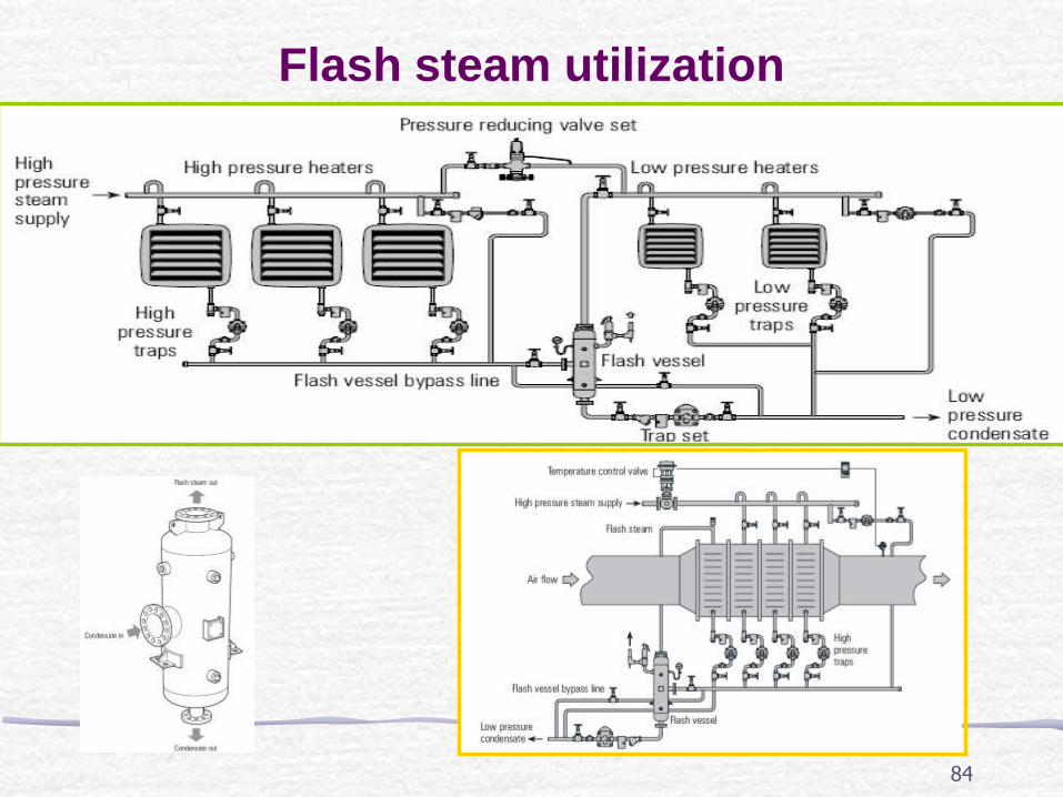
Flash steam utilization

85
Boiler blown down
• Surface Blow Down or Continuous Blow Down
• To maintain water concentration.
•Water is drained from area near
water surface;
• Water is drained continuously, it
may be called as Continuous
Blowdown;
• Heat recovery from blowdown is possible.

86
Boiler blown down
• It should be performed
when boilers operate under
low fired (LF) condition;
•To drain sludge;
•Water is drained from the
bottom of steam drum;
• Water is blown in a very
short period, 3-5 seconds.
Bottom blowdown
87
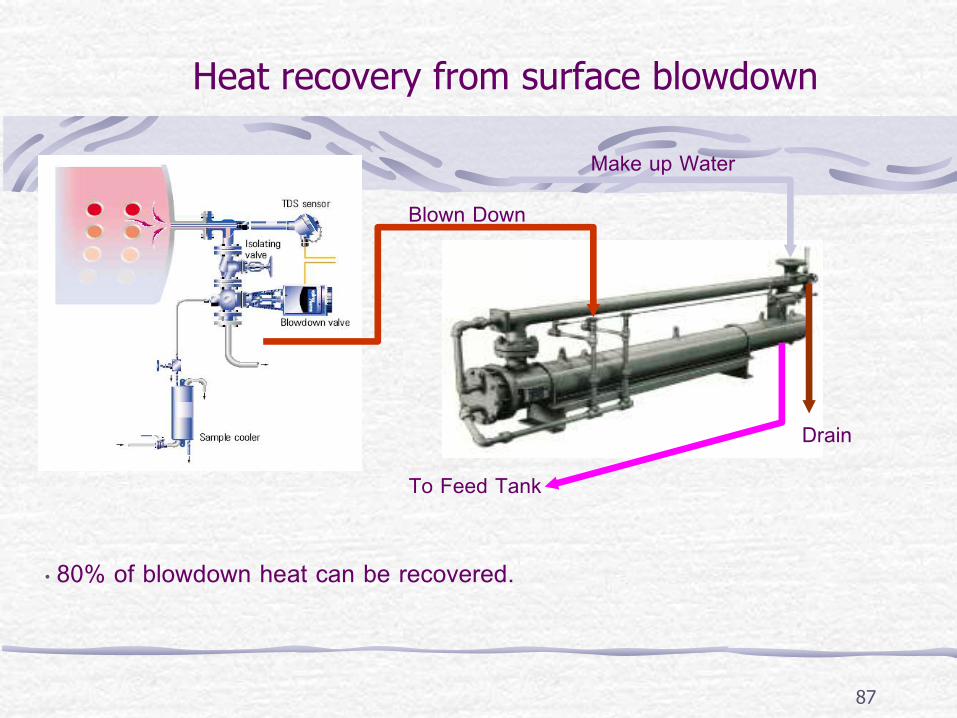
Heat recovery from surface blowdown
Blown Down
Make up Water
To Feed Tank
Drain
• 80% of blowdown heat can be recovered.
88
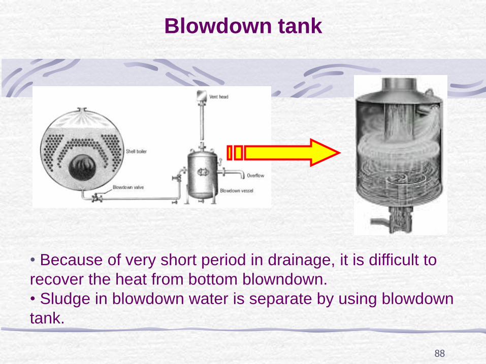
Blowdown tank
• Because of very short period in drainage, it is difficult to
recover the heat from bottom blowndown.
• Sludge in blowdown water is separate by using blowdown
tank.

89
Feed water
• Feed water system
• Feed water quality
• Blowdown rate
• Condensate utilization
90
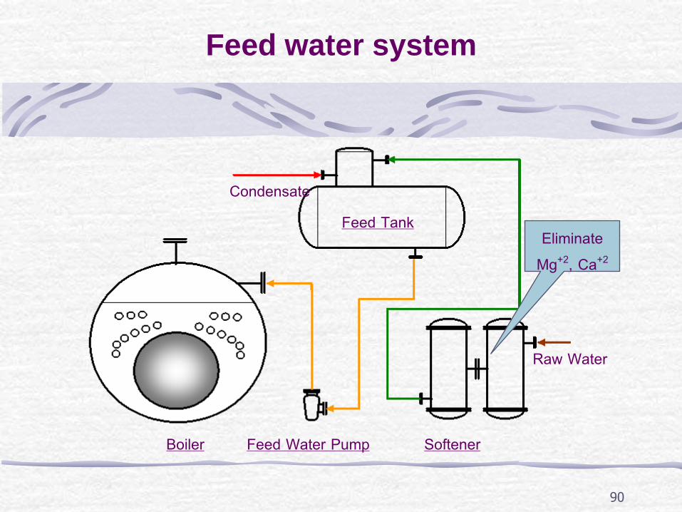
Feed water system
Feed Tank
Boiler Softener
Condensate
Feed Water Pump
Eliminate Mg+2, Ca+2
Raw Water

91
Water quality measurement
Conductivity meter
0.7 / ( / )TDS MicroCement cm s cm
( / )s cm
TDS Meter
92
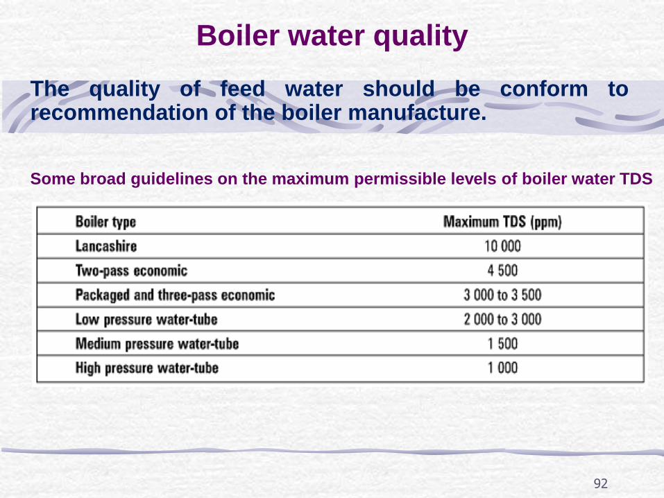
Boiler water quality
The quality of feed water should be conform to recommendation of the boiler manufacture.
Some broad guidelines on the maximum permissible levels of boiler water TDS
93
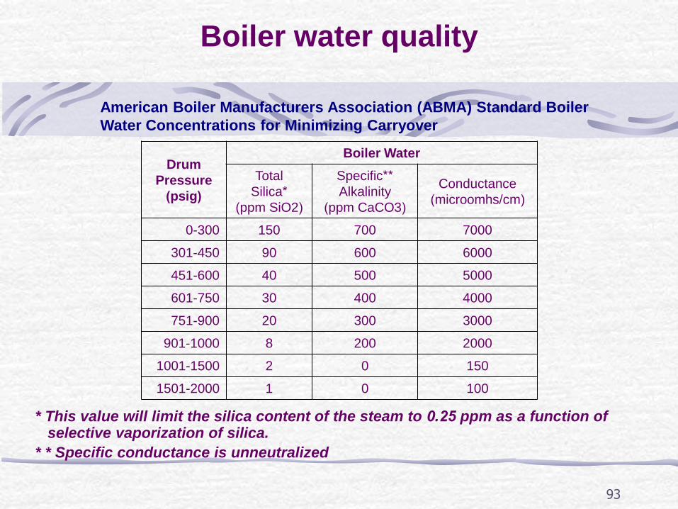
Boiler water quality
American Boiler Manufacturers Association (ABMA) Standard Boiler
Water Concentrations for Minimizing Carryover
Drum
Pressure
(psig)
Boiler Water
Total
Silica*
(ppm SiO2)
Specific**
Alkalinity
(ppm CaCO3)
Conductance
(microomhs/cm)
0-300 150 700 7000
301-450 90 600 6000
451-600 40 500 5000
601-750 30 400 4000
751-900 20 300 3000
901-1000 8 200 2000
1001-1500 2 0 150
1501-2000 1 0 100
* This value will limit the silica content of the steam to 0.25 ppm as a function of selective vaporization of silica. * * Specific conductance is unneutralized
94
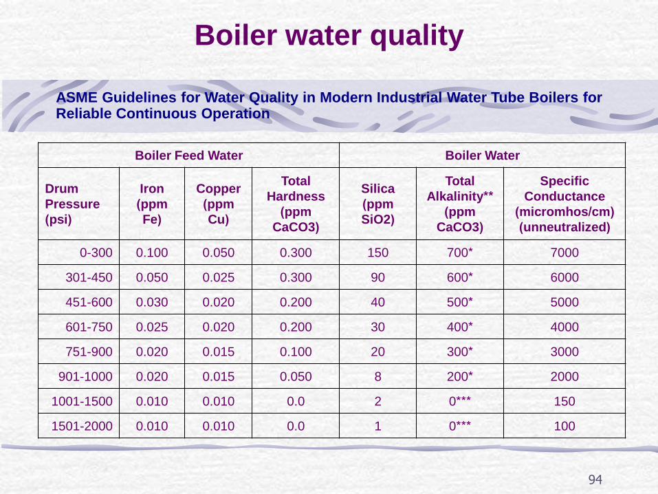
Boiler water quality
ASME Guidelines for Water Quality in Modern Industrial Water Tube Boilers for Reliable Continuous Operation
Boiler Feed Water Boiler Water
Drum
Pressure
(psi)
Iron
(ppm
Fe)
Copper
(ppm
Cu)
Total
Hardness
(ppm
CaCO3)
Silica
(ppm
SiO2)
Total
Alkalinity**
(ppm
CaCO3)
Specific
Conductance
(micromhos/cm)
(unneutralized)
0-300 0.100 0.050 0.300 150 700* 7000
301-450 0.050 0.025 0.300 90 600* 6000
451-600 0.030 0.020 0.200 40 500* 5000
601-750 0.025 0.020 0.200 30 400* 4000
751-900 0.020 0.015 0.100 20 300* 3000
901-1000 0.020 0.015 0.050 8 200* 2000
1001-1500 0.010 0.010 0.0 2 0*** 150
1501-2000 0.010 0.010 0.0 1 0*** 100

95
Blowdown rate
Anusorn Chinsuwan, Mechanical Engineering Department, Khon Kaen University, [email protected]
Make up Water
Condensate
make up
max allowable in boiler
%make up TDSMin %Blowdown (A) =
TDS
Steam generation rate = B ton/hr
Blowdown rate = 1000 litre/hr100-
A B
A

96
Steam generation rate (B) =1 ton/hr
4.3 1 Blowdown rate = 1000 litre/hr = 1000 45 l/hr
100- 100-4.3
A B
A
Example:
Compare blowdown rate of a boiler under conditions:
a) 100% make up water
b) 60% condensate recovery
The boiler has max allowable TDS of 3500ppm,TDS of make up water is 150
ppm and steam generation rate in 1 ton/hr.
make up
max allowable in boiler
%make up TDSMin %Blowdown (A) =
TDS
100 150 4.3
3500
make up
max allowable in boiler
%make up TDSMin %Blowdown (A) =
TDS
60 150 1.7
3500
Make up Water
Condensate
Case a)
Case b)
Case a)
1.7 1 Blowdown rate = 1000 litre/hr = 1000 18 l/hr
100- 100-1.7
A B
A
Case b)
97
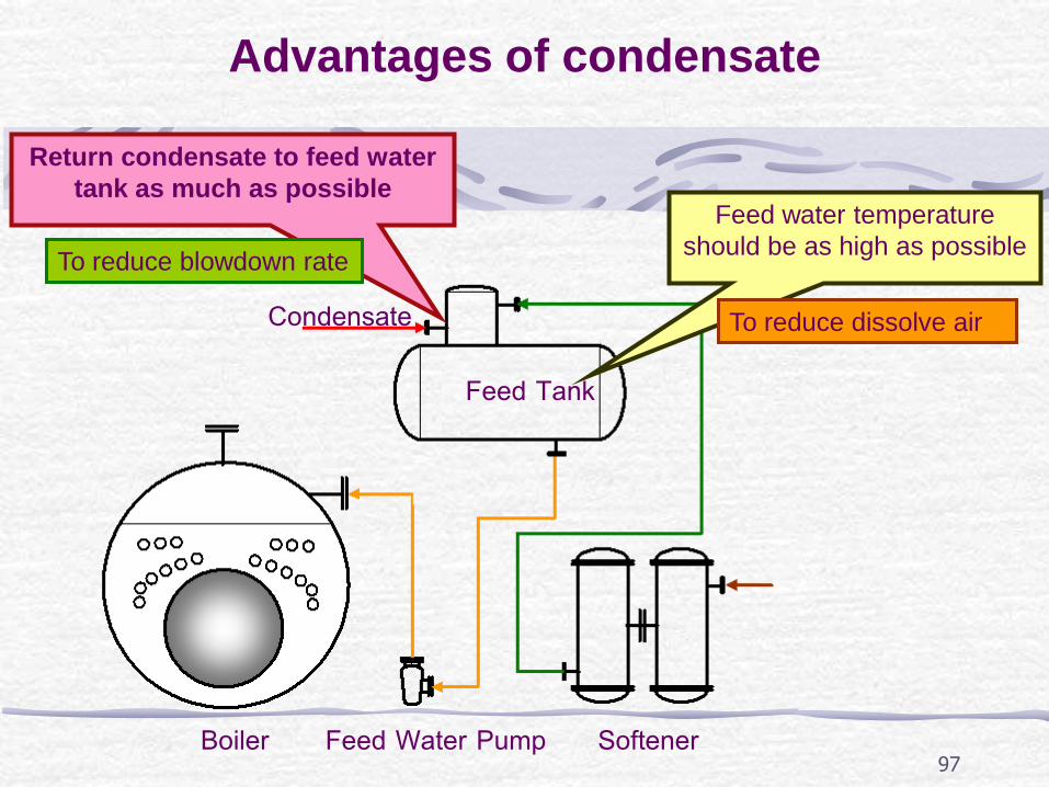
Advantages of condensate
Feed Tank
Boiler Softener
Condensate
Feed Water Pump
Return condensate to feed water
tank as much as possible Feed water temperature
should be as high as possible To reduce blowdown rate
To reduce dissolve air
98
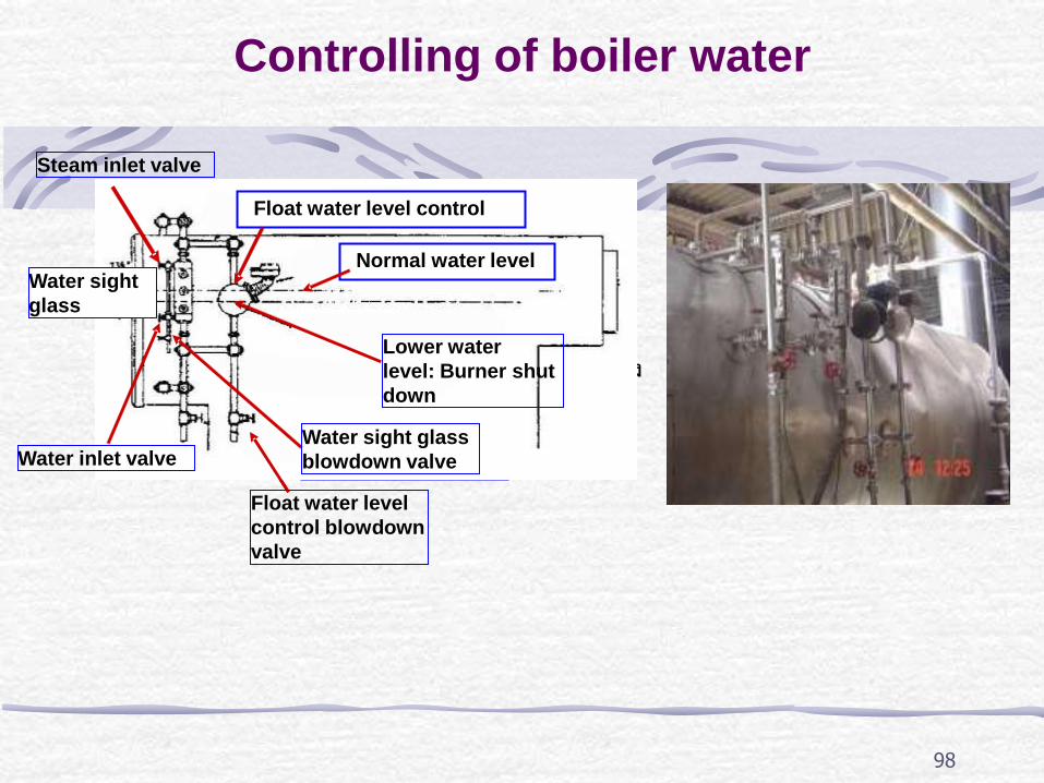
Controlling of boiler water
ระดับน ำ้ในหม้อไอน ำ้ปกติ
วำล์ว โบลว์ หลอดแก้ว
ระดับน ำ้ที่ตัดหัวเผำดับลง
เพื่อควำมปลอดภัย
ลูกลอยควบคุมระดับน ำ้ในหม้อไอน ำ้
Normal water level
Steam inlet valve
Float water level control
Water inlet valve Water sight glass
blowdown valve
Float water level
control blowdown
valve
Lower water
level: Burner shut
down
Water sight
glass
99
1. Steam Boiler Room Questions & Answers, Third Edition by
Stephen M.Elonka and Alex Higgins
2. Steam Boiler Operation by James J.Jackson,Prentice-Hall
Inc,New Jersey, 1980.
3. Boilers by Carl D.Shields, McGraw Hill Book Company,
U.S, 1961.
4. Industrial Heat Generation and Distribution -NIFES
Training Manual Issued For CEC – India Energy Bus Project
5. Practical Boiler Water Treatment by Leo.I.Pincus,McGraw
Hill Inc,New York, 1962.
6. Technical Papers, Boiler Congress-2000 Seminar, 11 & 12
January 2000.
REFERENCES