part ii – ibc fire safety - iccsafe.org icc public hearing ::: february 2008 rb175–07/08 r613.5...
TRANSCRIPT
ICC PUBLIC HEARING ::: February 2008 IRC-RB419
Exceptions:
1. Windows whose openings will not allow a 4-inch-diameter (102 mm) sphere to pass through the opening when the opening is in its largest opened position.
2. Openings that are provided with window guards that comply with ASTM F 2006 or F 2090. R613.2 Window fall prevention devices. Window fall prevention devices and window guards, where provided, shall comply with the requirements of ASTM F 2090. PART II – IBC FIRE SAFETY Delete and substitute as follows: 1405.12.2 Window sills. In Occupancy Groups R-2 and R-3, one- and two-family and multiple-family dwellings, where the opening of the sill portion of an operable window is located more than 72 inches (1829 mm) above the finished grade or other surface below, the lowest part of the clear opening of the window shall be a minimum of 24 inches (610 mm) above the finished floor surface of the room in which the window is located. Glazing between the floor and a height of 24 inches (610 mm) shall be fixed or have openings such that a 4-inch (102 mm) diameter sphere cannot pass.
Exception: Openings that are provided with window guards that comply with ASTM F 2006 or F 2090. 1405.12.2 Window fall prevention devices. Window fall prevention devices and window guards, where provided, shall comply with the requirements of ASTM F 2090.
Exception: Window fall prevention devices and window guards provided in windows where the lowest operable portion of the window is greater than 75 feet above adjacent grade or surface shall be permitted to comply with ASTM F 2006.
Reason: The 2006 IRC and IBC contain a newly adopted requirement for minimum sill heights in windows located more than 72” above grade as a means to prevent child falls through open windows. During the consideration of this proposal over several code cycles, WDMA expressed dismay with the lack of technical substantiation that demonstrated any positive impact of this requirement on the number of child window falls. In fact, WDMA’s opposition was due in large part to concerns about the unintended consequences such a requirement could have on fire safety. Despite objections from numerous parties, the ICC assembly approved the minimum sill height. During the committee hearings, the IRC B/E committee passed a resolution asking for the creation of a study group of ICC that would study the issue of child falls in an attempt to take a serious look at the problem and recommend solutions to improve child safety. The ICC Board took no action on that resolution until after the completion of the 2004-5 code development process. Since that time, the ICC Code Technology Committee was tasked with the responsibility to study the problem of child window falls, gather statistical data, consider associate factors and develop recommended actions. The CTC appointed a study group in January of 2007, and created a scope and objective document, outlining the work plan of the study group. WDMA believes that the work of the CTC window safety study group should have been commissioned and completed before adopting a code requirement that has the potential for negative impact on life safety.
The existing language is flawed. The text fails to specify that it is the lowest portion of an operable window as the point at which the measurement above grade is taken. Under that scoping error, a 6 foot tall casement window installed on a slab-on-grade foundation, with a sill height of 6 inches and located 16 inches above grade would have some of the operable portion located more than 72” above grade, and be subject to the minimum sill height. For this and other reasons, including the lack of technical justification for the sill height requirement, many state jurisdictions have chosen not to include the sill height minimum during adoption of the 2006 IBC and IRC. The more thorough review of the technical issues that is part of many state adoption processes resulted in careful consideration and removal of the requirement. This proposal leaves the requirement that window fall prevention devices and window guards, if furnished, meet consensus standards developed by ASTM and currently referenced in the IRC and IBC. The addition of the exception provides clear direction on the appropriate scope of the referenced standards to ensure that all guards or devices installed on windows at 75 or below be releasable to allow escape or rescue. Cost Impact: The code change proposal will not increase the cost of construction. PART I – IRC Public Hearing: Committee: AS AM D Assembly: ASF AMF DF PART II – IBC FIRE SAFETY Public Hearing: Committee: AS AM D Assembly: ASF AMF DF

IRC-RB420 ICC PUBLIC HEARING ::: February 2008
RB175–07/08 R613.5 Proponent: John Woestman, The Kellen Company, representing the Window and Door Manufacturers Association Add new text as follows: R613.5 Exterior door thresholds. Exterior sliding and side-hinged doors, other than the egress door required by Section 311.2, shall have a maximum threshold height of 7 ¾", and shall be installed in accordance with R311.3.2. (Renumber subsequent sections) Reason: This proposal complements R311.3.2 and clarifies, in the Exterior Windows and Doors section of the code, the maximum threshold height. This proposal does not modify requirements in Chapter 3 but clearly communicates in Chapter 6 that 7 ¾” is the maximum allowable threshold assembly height. For egress doors, requirements in R311.3.1 limit the threshold height in relation to floors and landings to 1.5 inches. Cost Impact: The code change proposal will not increase the cost of construction. Public Hearing: Committee: AS AM D Assembly: ASF AMF DF
RB176–07/08 R613.8 Proponent: Julie Ruth, JRuth Code Consulting, representing American Architectural Manufacturers Association (AAMA) Revise as follows: R613.8 Anchorage methods. The methods cited in this section apply only to anchorage of window and glass door assemblies to the main force-resisting system. R613.8.1 Anchoring requirements. Window and glass door assemblies shall be anchored in accordance with the published manufacturer’s recommendations to achieve the design pressure specified. Substitute anchoring systems used for substrates not specified by the fenestration manufacturer shall provide equal or greater anchoring performance as demonstrated by accepted engineering practice. R613.8.2 Anchorage details. Products shall be anchored in accordance with the minimum requirements illustrated in Figures R613.8(1), R613.8(2), R613.8(3), R613.8(4), R613.8(5), R613.8(6), R613.8(7) and R613.8(8). R613.8.2.1 Masonry, concrete or other structural substrate. Where the wood shim or buck thickness is less than 11/2 inches (38 mm), window and glass door assemblies shall be anchored through the jamb, or by jamb clip and anchors shall be embedded directly into the masonry, concrete or other substantial substrate material. Anchors shall adequately transfer load from the window or door frame into the rough opening substrate [see Figures R613.8(1) and R613.8(2).] Where the wood shim or buck thickness is 11/2 inches (38 mm) or more, the buck is securely fastened to the masonry, concrete or other substantial substrate, and the buck extends beyond the interior face of the window or door frame, window and glass door assemblies shall be anchored through the jamb, or by jamb clip, or through the flange to the secured wood buck. Anchors shall be embedded into the secured wood buck to adequately transfer load from the window or door frame assembly [Figures R613.8(3), R613.8(4) and R613.8(5)]. R613.8.2.2 Wood or other approved framing material. Where the framing material is wood or other approved framing material, window and glass door assemblies shall be anchored through the frame, or by frame clip, or through the flange. Anchors shall be embedded into the frame construction to adequately transfer load [Figures R613.8(6), R613.8(7) and R613.8(8)]. Reason: This proposal expands the scope of the anchorage requirements of Section R613.8 from glass doors to all doors. When Section R613 was first developed for the 2000 International Residential Code, its scope was limited to windows and glass doors. Since that time the scope of the section has been expanded so that it now addresses all types of residential doors. Although other subsections of R613 have been appropriately revised to reflect this change, Section R613.8 has not. This proposal makes that revision. The anchorage requirements of Section R613.8 are appropriate for all types of doors, not just glass doors. Therefore the committee is urged to expand the scope of Section R613.8 by approving this change. Cost Impact: The code change proposal will not increase the cost of construction. Public Hearing: Committee: AS AM D Assembly: ASF AMF DF

ICC PUBLIC HEARING ::: February 2008 IRC-RB421
RB177–07/08 R301.3, R614.2 Proponent: Edward L. Keith, APA – The Engineered Wood Association Revise as follows: R301.3 (Supp) Story height. Buildings constructed in accordance with these provisions shall be limited to story heights of not more than the following:
1. For wood wall framing, the laterally unsupported bearing wall stud height permitted by Table R602.3(5) plus a height of floor framing not to exceed 16 inches.
Exception: For wood framed wall buildings with bracing in accordance with Table R602.10.1(1), the wall stud clear height used to determine the maximum permitted story height may be increased to 12 feet (3658 mm) without requiring an engineered design for the building wind and seismic force resisting systems provided that the length of bracing required by Table R602.10.1(1) is increased by multiplying by a factor of 1.20. Wall studs are still subject to the requirements of this section.
2. For steel wall framing, a stud height of 10 feet (3048 mm), plus a height of floor framing not to exceed 16 inches (406 mm).
3. For masonry walls, a maximum bearing wall clear height of 12 feet (3658 mm) plus a height of floor framing not to exceed 16 inches (406 mm).
Exception: An additional 8 feet (2438 mm) is permitted for gable end walls.
4. For insulating concrete form walls, the maximum bearing wall height per story as permitted by Section R611
tables plus a height of floor framing not to exceed 16 inches (406 mm). 5. For structural insulated panel walls, the maximum bearing wall height per story as permitted by Section R614 tables plus a height of floor framing not to shall not exceed 10 feet (3048 mm) plus a height of floor framing not to exceed 16 inches (406 mm). Individual walls or walls studs shall be permitted to exceed these limits as permitted by Chapter 6 provisions, provided story heights are not exceeded. Floor framing height shall be permitted to exceed these limits provided the story height does not exceed 11 feet 7 inches (3531 mm). An engineered design shall be provided for the wall or wall framing members when they exceed the limits of Chapter 6. Where the story height limits are exceeded, an engineered design shall be provided in accordance with the International Building Code for the overall wind and seismic force resisting systems. R614.2 (Supp) Applicability limits. The provisions of this section shall control the construction of exterior structural insulated panel walls and interior load-bearing structural insulated panel walls for buildings not greater than 60 feet (18 288 mm) in length perpendicular to the joist or truss span, not greater than 40 feet (10 973 mm) in width parallel to the joist span or truss and not greater than two stories in height with each story wall not greater than 10 feet (3048 mm) high. All exterior walls installed in accordance with the provisions of this section shall be considered as load-bearing walls. Structural insulated panel walls constructed in accordance with the provisions of this section shall be limited to sites subjected to a maximum design wind speed of 130 miles per hour, Exposure A, B or C, and a maximum ground snow load of 70 pounds per foot (3.35 kN/m2), and Seismic Zones A, B, and C. Reason: The purpose of the code change is to reformat item 5 to be similar to the other items listed. This reformatting will make the provisions for what constitutes wall height and story height the same for all wall construction types. Approval of this proposal will make the basic provision for wall height for all wall types (wood frame, steel frame, masonry, insulated concrete form and SIP panel) equal to 10 feet with an allowance for an additional height of 16” for floor framing. This proposal will make the code consistent, rational and easier to read and interpret. In addition this language change reflects actual tested conditions for SIP products. All of the testing on the SIPs wall panels was conducted with full 8- and 10-foot wall height panel specimen. The proposed language more accurately represents the actual tested panels and reduces the chances for erroneous interpretation. Cost Impact: The code change proposal will not increase the cost of construction. Public Hearing: Committee: AS AM D Assembly: ASF AMF DF

IRC-RB422 ICC PUBLIC HEARING ::: February 2008
RB178–07/08 R614.3.1, Table R614.3.1 (New), Chapter 43 (New) Proponent: Lorraine Ross, Intech Consulting, Inc., representing The Center for the Polyurethanes Industry (formerly Alliance for the Polyurethanes Industry) 1. Revise as follows: R614.3.1 (Supp) Core. The core material of structural insulated panels (SIP) shall be composed of foam plastic insulation meeting one of the following requirements: of 1. ASTM C 578, and shall have a minimum density of 0.90 lb/cu ft or 2. Polyurethane meeting the physical properties shown in Table R614.3.1, or, 3. an approved alternative. All cores shall meet the requirements of Section R314. Structural insulated panels (SIP) core insulation shall bear a label with the manufacturer identification, product standard and type, flame spread/smoke-developed index and the name of quality assurance agency. 2. Add new table as follows:
TABLE R614.3.1 MINIMUM PROPERTIES FOR POLYURETHANE INSULATION USED AS SIPS CORE
PHYSICAL PROPERTY
POLYURETHANE
Density, core nominal, (ASTM D 1622) 2.0 lb/ft3 Compressive resistance at yield or 10% deformation, whichever occurs first, (ASTM D 1621) 19 psi (perpendicular to
rise) Flexural strength, min, ( ASTM C 203) 30 psi Tensile strength, min. (ASTM D 1623) 35 psi Shear strength, min, (ASTM C 273) 25 psi Substrate adhesion, min, (ASTM D 1623) 22 psi Water vapor permeance of 1.00-in. thickness, max, (ASTM E96) 2.3 perm Water absorption by total immersion, max, (ASTM C 272) 4.3 % (volume) Dimensional stability (change in dimensions), max, (ASTM D2126 (7 days at 158°F/100 % humidity and 7 days at -20°F)
2 %
3. Add standards to Chapter 43 as follows: ASTM
C 203-05a Standard Test Methods for Breaking Load and Flexural Properties of Block-Type Thermal Insulation
C 272-01 Standard Test Method for Water Absorption of Core Materials for Structural Sandwich Constructions
C 273-00e1 Standard Test Method for Shear Properties of Sandwich Core Materials D 1622-03 Standard Test Method for Apparent Density of Rigid Cellular Plastics D 1623-78(1995) Standard Test Method for Tensile and Tensile Adhesion Properties of Rigid Cellular Plastics D 2126-04 Standard Test Method for Response of Rigid Cellular Plastics to Thermal and Humid Aging
Reason: This proposal adds polyurethane foam as alternate core insulation for Structural Insulated Panels (SIPS). The newly proposed Table contains specific physical properties for qualifying polyurethane in this application. A new section (SECTION R614 STRUCTURAL INSULATED PANEL WALL CONSTRUCTION) was added to the 2007 Supplement of the IRC, which included only polystyrene as the core insulation material. A Public Comment [RB 34 (06-07)] proposed the addition of polyurethane foam insulation as a core material. However, necessary testing data was not available in time for the May 2007 ICC hearings in Rochester, so the Public Comment was withdrawn. This new proposal widens the choices for SIPS manufacturers in selecting a core material. SIPS containing polyurethane are currently slated for testing at the APA laboratories using the same testing protocol as was used for the acceptance of SIPS in the IRC 2007 Supplement. Full data will be available and presented at the February 2008 ICC Hearings in Palm Springs. SIPS containing polyurethane are currently slated for testing at the APA laboratories using the same testing protocol as was used for the acceptance of SIPS in the IRC 2007 Supplement. Full data will be available and presented at the February 2008 ICC Hearings in Palm Springs CA.

ICC PUBLIC HEARING ::: February 2008 IRC-RB423
Cost Impact: This code change proposal will not increase the cost of construction because it increases the choices of core insulation for SIPS. Analysis: A review of the standard proposed for inclusion in the code, ASTM C 203, C 272, C 273, D 1622, D 1623, D2126, for compliance with ICC criteria for referenced standards given in Section 3.6 of Council Policy #CP 28 will be posted on the ICC website on or before January 15, 2008. Public Hearing: Committee: AS AM D Assembly: ASF AMF DF
RB179–07/08 R202, R301.2.1.1, R301.2.2.2.1, R301.2.2.4.1, R301.3, M1308.1, M2101.6, P2603.2, R614.1, R614.2. R614.3, R614.3.1, R614.3.2, Table R614.3.2, R614.3.5, R614.3.6 (New), R614.4, R614.4.1, R614.5, Table R614.5(1), Table R614.5(2), Figure R614.5(1)-(2)-(3)-(4)-(5)-(6), R614.5.1, Figure R614.5.1, R614.5.2, R614.5.3, R614.8, Figure R614.8, R614.9, Figure R614.9, R614.10, Table R614.10, R614.10.1 Proponent: Edward L. Keith, APA – The Engineered Wood Association 1. Add new definition as follows:
SECTION R202 GENERAL DEFINITIONS
CAP PLATE. The top plate of the double top plates used in structural insulated panel (SIP) construction. The cap plate is cut to match the panel thickness such that it overlaps the wood structural panel facing on both sides. 2. Revise as follows: CORE. (Supp) The light-weight middle section of the sandwich structural insulated panel composed of foam plastic insulation, which provides the link between the two facing shells. FACING. (Supp) The wood structural wood panel facers facings that form the two outmost rigid layers of the structural insulated panel. PANEL THICKNESS. (Supp) Thickness of core plus two layers structural wood panel facers. SPLINE. (Supp) A long, flat, pliable strip of wood structural panel cut from the same material used for the panel facers facings, used to connect two structural insulated panels. The strip (spline) fits into a groove cut into the longitudinal vertical edges of the two structural insulated panels to be joined. Splines are used in pairs, one behind each facing of the structural insulated panels being spaced connected as per Figure R614.8. STRUCTURAL INSULATED PANEL (SIP). (Supp) A structural sandwich panel which consists of a light weight foam plastic core securely laminated between two thin, rigid wood structural panel facings. R301.2.1.1 (Supp) Design Criteria. R301.2.1.1 Design criteria. In regions where the basic wind speeds from Figure R301.2(4) equal or exceed 100 miles per hour (45 m/s) in hurricane-prone regions, or 110 miles per hour (49 m/s) elsewhere, the design of buildings shall be in accordance with one of the following methods. The elements of design not addressed by those documents in Items 1 through 4 shall be in accordance with this code.
1. American Forest and Paper Association (AF&PA) Wood Frame Construction Manual for One- and Two-Family Dwellings (WFCM); or
2. Southern Building Code Congress International Standard for Hurricane Resistant Residential Construction (SSTD 10); or
3. Minimum Design Loads for Buildings and Other Structures (ASCE-7); or 4. American Iron and Steel Institute (AISI), Standard for Cold-Formed Steel Framing—Prescriptive Method For
One- and Two-Family Dwellings (COFS/PM) with Supplement to Standard for Cold-Formed Steel Framing— Prescriptive Method For One- and Two-Family Dwellings.
5. Concrete construction shall be designed in accordance with the provisions of this code. 6. Structural insulated panels (SIP) walls shall be designed in accordance with the provisions of this code.

IRC-RB424 ICC PUBLIC HEARING ::: February 2008
R301.2.2.2.1 (Supp) Weights of materials. Average dead loads shall not exceed 15 pounds per square foot (720 Pa) for the combined roof and ceiling assemblies (on a horizontal projection) or 10 pounds per square foot (480 Pa) for floor assemblies, except as further limited by Section R301.2.2. Dead loads for walls above grade shall not exceed:
1. Fifteen pounds per square foot (720 Pa) for exterior light-frame wood walls. 2. Fourteen pounds per square foot (670 Pa) for exterior light-frame cold-formed steel walls. 3. Ten pounds per square foot (480 Pa) for interior light-frame wood walls. 4. Five pounds per square foot (240 Pa) for interior light-frame cold-formed steel walls. 5. Eighty pounds per square foot (3830 Pa) for 8-inch-thick (203 mm) masonry walls. 6. Eighty-five pounds per square foot (4070 Pa) for 6-inch-thick (152 mm) concrete walls. 7. Ten psf (0.48 kN/m2) for structural insulated panel SIP walls.
Exceptions:
1. Roof and ceiling dead loads not exceeding 25 pounds per square foot (1190 Pa) shall be permitted provided the wall bracing amounts in Chapter 6 are increased in accordance with Table R301.2.2.2.1.
2. Light-frame walls with stone or masonry veneer shall be permitted in accordance with the provisions of Sections R702.1 and R703.
3. Fireplaces and chimneys shall be permitted in accordance with Chapter 10. R301.2.2.3.1 (Supp) Height limitations. Wood framed buildings shall be limited to three stories above grade or the limits given in Table R602.10.1. Cold-formed steel framed buildings shall be limited to two stories above grade in accordance with COFS/PM. Mezzanines as defined in Section R202 shall not be considered as stories. Structural insulated panels SIP buildings shall be limited to two stories above grade. R301.3 (Supp) Story height. Buildings constructed in accordance with these provisions shall be limited to story heights of not more than the following:
1. For wood wall framing, the laterally unsupported bearing wall stud height permitted by Table R602.3(5) plus a height of floor framing not to exceed 16 inches.
Exception: For wood framed wall buildings with bracing in accordance with Table R602.10.1(1), the wall stud clear height used to determine the maximum permitted story height may be increased to 12 feet (3658 mm) without requiring an engineered design for the building wind and seismic force resisting systems provided that the length of bracing required by Table R602.10.1(1) is increased by multiplying by a factor of 1.20. Wall studs are still subject to the requirements of this section.
2. For steel wall framing, a stud height of 10 feet (3048 mm), plus a height of floor framing not to exceed 16 inches (406 mm).
3. For masonry walls, a maximum bearing wall clear height of 12 feet (3658 mm) plus a height of floor framing not to exceed 16 inches (406 mm).
Exception: An additional 8 feet (2438 mm) is permitted for gable end walls.
4. For insulating concrete form walls, the maximum bearing wall height per story as permitted by Section R611
tables plus a height of floor framing not to exceed 16 inches (406 mm). 5. For structural insulated panel SIP walls, the maximum bearing wall height per story as permitted by Section R614 tables plus a height of floor framing not to exceed 10 feet (3048 mm). Individual walls or walls studs shall be permitted to exceed these limits as permitted by Chapter 6 provisions, provided story heights are not exceeded. Floor framing height shall be permitted to exceed these limits provided the story height does not exceed 11 feet 7 inches (3531 mm). An engineered design shall be provided for the wall or wall framing members when they exceed the limits of Chapter 6. Where the story height limits are exceeded, an engineered design shall be provided in accordance with the International Building Code for the overall wind and seismic force resisting systems. M1308.1 (Supp) Drilling and notching. Wood-framed structural members shall be drilled, notched or altered in accordance with the provisions of Sections R502.8, R602.6, R602.6.1 and R802.7. Holes in cold-formed, steel-framed, load-bearing members shall be permitted only in accordance with Sections R505.2, R603.2 and R804.2. In accordance with the provisions of Sections R505.3.5, R603.3.4 and R804.3.5, cutting and notching of flanges and lips of cold-formed, steel-framed, load-bearing members shall not be permitted. Structural insulated panels (SIPs) shall be drilled and notched or altered in accordance with the provisions of Section R614.
ICC PUBLIC HEARING ::: February 2008 IRC-RB425
M2101.6 (Supp) Drilling and notching. Wood-framed structural members shall be drilled, notched or altered in accordance with the provisions of Sections R502.6, R602.6, R602.6.1 and R802.6. Holes in cold-formed, steel-framed, load-bearing members shall be permitted only in accordance with Sections R506.2, R603.2 and R804.2. In accordance with the provisions of Sections R505.3.5, R603.3.4 and R804.3.5, cutting and notching of flanges and lips of cold-formed, steel-framed, load-bearing members shall not be permitted. Structural insulated panels (SIPs) shall be drilled and notched or altered in accordance with the provisions of Section R614. P2603.2 (Supp) Drilling and notching. Wood-framed structural members shall not be drilled, notched or altered in any manner except as provided in Sections R502.8, R602.5, R602.6, R802.7 and R802.7.1. Holes in cold-formed steel-framed load-bearing members shall be permitted only in accordance with Sections R505.2, R603.2 and R804.2. In accordance with the provisions of Sections R603.3.4 and R804.3.5 cutting and notching of flanges and lips of cold-formed steel-framed load-bearing members shall not be permitted. Structural insulated panels (SIPs) shall be drilled and notched or altered in accordance with the provisions of Section R614. R614.1 (Supp) General. Structural Insulated Panel insulated panel (SIP) walls shall be designed in accordance with the provisions of this section. When the provisions of this section are used to design structural insulated panel walls, project drawings, typical details and specifications are not required to bear the seal of the architect or engineer responsible for design, unless otherwise required by the state law of the jurisdiction having authority. R614.2 (Supp) Applicability Limits. The provisions of this section shall control the construction of exterior structural Insulated panel walls and interior load-bearing structural insulated panel walls for buildings not greater than 60 feet (18 288 mm) in length perpendicular to the joist or truss span, not greater than 40 feet (10 973 mm) in width parallel to the joist span or truss span, and not greater than two stories in height with each story wall not greater than 10 feet (3048 mm) high. All exterior walls installed in accordance with the provisions of this section shall be considered as load-bearing walls. Structural insulated panel walls constructed in accordance with the provisions of this section shall be limited to sites subjected to a maximum design wind speed of 130 miles per hour Exposure A, B or C and a maximum ground snow load of 70 pounds per foot (3.35 kN/m2), and Seismic Zones A, B, and C.
R614.3 (Supp) Materials. Structural insulated panels (SIPS) SIPs shall comply with the following criteria:
R614.3.1 (Supp) Core. The core material of structural insulated panels SIPs shall be composed of foam plastic insulation meeting the requirements of ASTM C 578, and shall have a minimum density of 0.90 lb/cu ft or an approved alternate. All cores shall meet the requirements of Section R314. Structural insulated panels SIP core insulation shall bear a label with the manufacturer identification, product standard and type, flame-spread/smoke-developed index and name of quality assurance agency.
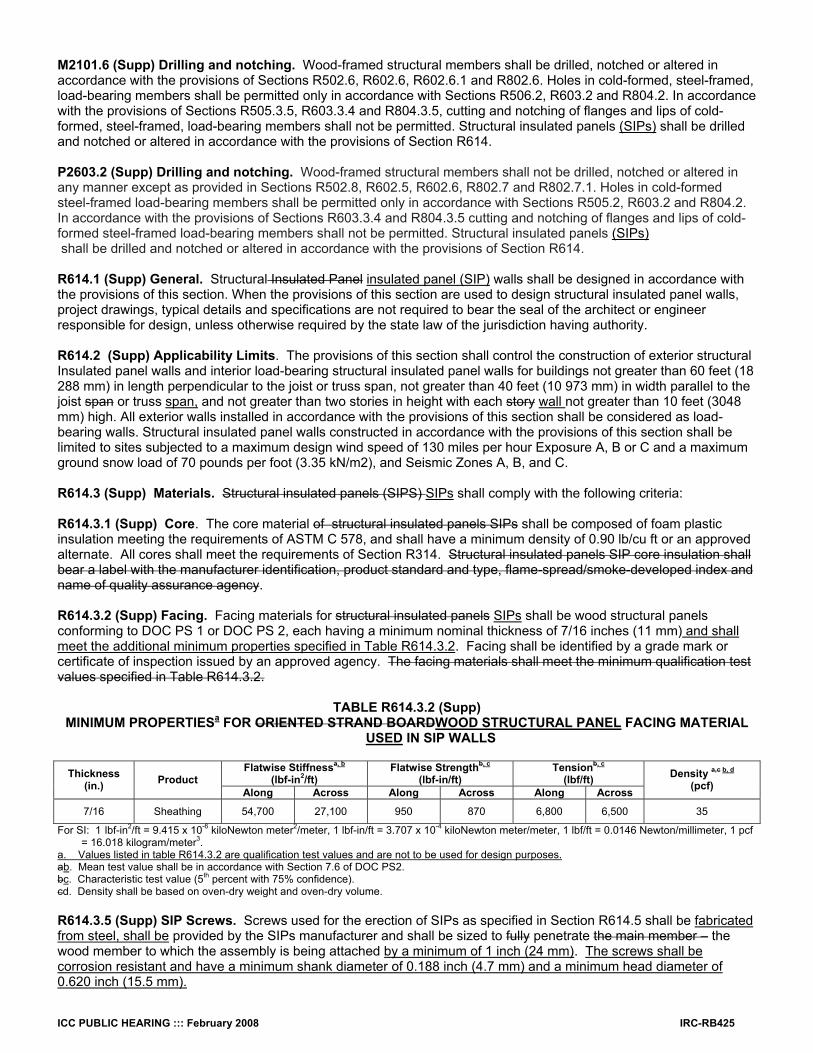
R614.3.2 (Supp) Facing. Facing materials for structural insulated panels SIPs shall be wood structural panels conforming to DOC PS 1 or DOC PS 2, each having a minimum nominal thickness of 7/16 inches (11 mm) and shall meet the additional minimum properties specified in Table R614.3.2. Facing shall be identified by a grade mark or certificate of inspection issued by an approved agency. The facing materials shall meet the minimum qualification test values specified in Table R614.3.2.
TABLE R614.3.2 (Supp)
MINIMUM PROPERTIESa FOR ORIENTED STRAND BOARDWOOD STRUCTURAL PANEL FACING MATERIAL USED IN SIP WALLS
Flatwise Stiffnessa, b
(lbf-in2/ft) Flatwise Strengthb, c
(lbf-in/ft) Tensionb, c
(lbf/ft) Thickness (in.) Product
Along Across Along Across Along Across
Density a,c b, d (pcf)
7/16 Sheathing 54,700 27,100 950 870 6,800 6,500 35
For SI: 1 lbf-in2/ft = 9.415 x 10⁻⁶ kiloNewton meter2/meter, 1 lbf-in/ft = 3.707 x 10⁻⁴ kiloNewton meter/meter, 1 lbf/ft = 0.0146 Newton/millimeter, 1 pcf = 16.018 kilogram/meter3.
a. Values listed in table R614.3.2 are qualification test values and are not to be used for design purposes. ab. Mean test value shall be in accordance with Section 7.6 of DOC PS2. bc. Characteristic test value (5th percent with 75% confidence). cd. Density shall be based on oven-dry weight and oven-dry volume. R614.3.5 (Supp) SIP Screws. Screws used for the erection of SIPs as specified in Section R614.5 shall be fabricated from steel, shall be provided by the SIPs manufacturer and shall be sized to fully penetrate the main member – the wood member to which the assembly is being attached by a minimum of 1 inch (24 mm). The screws shall be corrosion resistant and have a minimum shank diameter of 0.188 inch (4.7 mm) and a minimum head diameter of 0.620 inch (15.5 mm).
IRC-RB426 ICC PUBLIC HEARING ::: February 2008
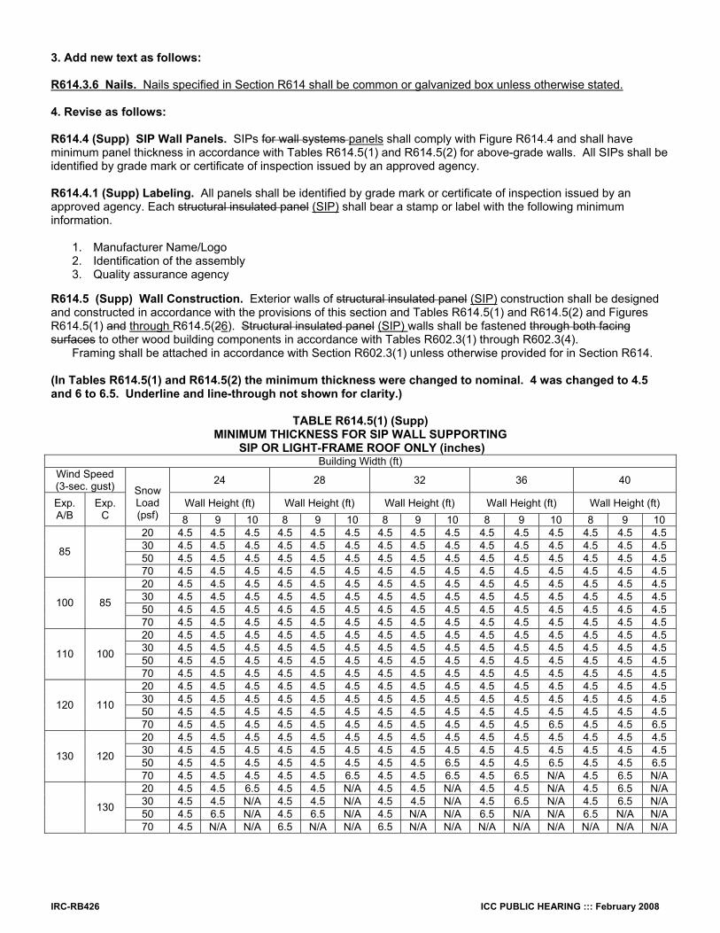
3. Add new text as follows: R614.3.6 Nails. Nails specified in Section R614 shall be common or galvanized box unless otherwise stated. 4. Revise as follows: R614.4 (Supp) SIP Wall Panels. SIPs for wall systems panels shall comply with Figure R614.4 and shall have minimum panel thickness in accordance with Tables R614.5(1) and R614.5(2) for above-grade walls. All SIPs shall be identified by grade mark or certificate of inspection issued by an approved agency.
R614.4.1 (Supp) Labeling. All panels shall be identified by grade mark or certificate of inspection issued by an approved agency. Each structural insulated panel (SIP) shall bear a stamp or label with the following minimum information. 1. Manufacturer Name/Logo 2. Identification of the assembly 3. Quality assurance agency
R614.5 (Supp) Wall Construction. Exterior walls of structural insulated panel (SIP) construction shall be designed and constructed in accordance with the provisions of this section and Tables R614.5(1) and R614.5(2) and Figures R614.5(1) and through R614.5(26). Structural insulated panel (SIP) walls shall be fastened through both facing surfaces to other wood building components in accordance with Tables R602.3(1) through R602.3(4).
Framing shall be attached in accordance with Section R602.3(1) unless otherwise provided for in Section R614. (In Tables R614.5(1) and R614.5(2) the minimum thickness were changed to nominal. 4 was changed to 4.5 and 6 to 6.5. Underline and line-through not shown for clarity.)
TABLE R614.5(1) (Supp)
MINIMUM THICKNESS FOR SIP WALL SUPPORTING SIP OR LIGHT-FRAME ROOF ONLY (inches)
Building Width (ft) Wind Speed (3-sec. gust) 24 28 32 36 40
Wall Height (ft) Wall Height (ft) Wall Height (ft) Wall Height (ft) Wall Height (ft) Exp. A/B
Exp. C
Snow Load (psf) 8 9 10 8 9 10 8 9 10 8 9 10 8 9 10 20 4.5 4.5 4.5 4.5 4.5 4.5 4.5 4.5 4.5 4.5 4.5 4.5 4.5 4.5 4.5 30 4.5 4.5 4.5 4.5 4.5 4.5 4.5 4.5 4.5 4.5 4.5 4.5 4.5 4.5 4.5 50 4.5 4.5 4.5 4.5 4.5 4.5 4.5 4.5 4.5 4.5 4.5 4.5 4.5 4.5 4.5 85
70 4.5 4.5 4.5 4.5 4.5 4.5 4.5 4.5 4.5 4.5 4.5 4.5 4.5 4.5 4.5 20 4.5 4.5 4.5 4.5 4.5 4.5 4.5 4.5 4.5 4.5 4.5 4.5 4.5 4.5 4.5 30 4.5 4.5 4.5 4.5 4.5 4.5 4.5 4.5 4.5 4.5 4.5 4.5 4.5 4.5 4.5 50 4.5 4.5 4.5 4.5 4.5 4.5 4.5 4.5 4.5 4.5 4.5 4.5 4.5 4.5 4.5 100 85
70 4.5 4.5 4.5 4.5 4.5 4.5 4.5 4.5 4.5 4.5 4.5 4.5 4.5 4.5 4.5 20 4.5 4.5 4.5 4.5 4.5 4.5 4.5 4.5 4.5 4.5 4.5 4.5 4.5 4.5 4.5 30 4.5 4.5 4.5 4.5 4.5 4.5 4.5 4.5 4.5 4.5 4.5 4.5 4.5 4.5 4.5 50 4.5 4.5 4.5 4.5 4.5 4.5 4.5 4.5 4.5 4.5 4.5 4.5 4.5 4.5 4.5 110 100
70 4.5 4.5 4.5 4.5 4.5 4.5 4.5 4.5 4.5 4.5 4.5 4.5 4.5 4.5 4.5 20 4.5 4.5 4.5 4.5 4.5 4.5 4.5 4.5 4.5 4.5 4.5 4.5 4.5 4.5 4.5 30 4.5 4.5 4.5 4.5 4.5 4.5 4.5 4.5 4.5 4.5 4.5 4.5 4.5 4.5 4.5 50 4.5 4.5 4.5 4.5 4.5 4.5 4.5 4.5 4.5 4.5 4.5 4.5 4.5 4.5 4.5 120 110
70 4.5 4.5 4.5 4.5 4.5 4.5 4.5 4.5 4.5 4.5 4.5 6.5 4.5 4.5 6.5 20 4.5 4.5 4.5 4.5 4.5 4.5 4.5 4.5 4.5 4.5 4.5 4.5 4.5 4.5 4.5 30 4.5 4.5 4.5 4.5 4.5 4.5 4.5 4.5 4.5 4.5 4.5 4.5 4.5 4.5 4.5 50 4.5 4.5 4.5 4.5 4.5 4.5 4.5 4.5 6.5 4.5 4.5 6.5 4.5 4.5 6.5 130 120
70 4.5 4.5 4.5 4.5 4.5 6.5 4.5 4.5 6.5 4.5 6.5 N/A 4.5 6.5 N/A 20 4.5 4.5 6.5 4.5 4.5 N/A 4.5 4.5 N/A 4.5 4.5 N/A 4.5 6.5 N/A 30 4.5 4.5 N/A 4.5 4.5 N/A 4.5 4.5 N/A 4.5 6.5 N/A 4.5 6.5 N/A 50 4.5 6.5 N/A 4.5 6.5 N/A 4.5 N/A N/A 6.5 N/A N/A 6.5 N/A N/A 130
70 4.5 N/A N/A 6.5 N/A N/A 6.5 N/A N/A N/A N/A N/A N/A N/A N/A

ICC PUBLIC HEARING ::: February 2008 IRC-RB427
For SI: 1 inch = 25.4 mm; 1 foot = 304.8 mm. Maximum dDeflection criteria: L/240. Maximum rRoof dead load: 7 10 psf. Maximum roof live load: 70 psf. Maximum cCeiling dead load: 5 psf. Maximum ceiling live load: 20 psf. Wind loads based on Table R301.2 (2). N/A indicates not applicable.
TABLE R614.5(2) (Supp) MINIMUM THICKNESS FOR SIP WALLS SUPPORTING
SIP OR LIGHT-FRAME ONE STORY AND ROOF (Inches) Building Width (ft)
Wind Speed (3-sec. gust) 24 28 32 36 40
Wall Height (ft) Wall Height (ft) Wall Height (ft) Wall Height (ft) Wall Height (ft) Exp. A/B
Exp. C
Snow Load (psf)
8 9 10 8 9 10 8 9 10 8 9 10 8 9 10 20 4.5 4.5 4.5 4.5 4.5 4.5 4.5 4.5 4.5 4.5 4.5 4.5 4.5 4.5 4.5 30 4.5 4.5 4.5 4.5 4.5 4.5 4.5 4.5 4.5 4.5 4.5 4.5 4.5 4.5 4.5 50 4.5 4.5 4.5 4.5 4.5 4.5 4.5 4.5 4.5 4.5 4.5 4.5 4.5 4.5 4.5 85
70 4.5 4.5 4.5 4.5 4.5 4.5 4.5 4.5 4.5 4.5 4.5 6.5 6.5 6.5 6.5 20 4.5 4.5 4.5 4.5 4.5 4.5 4.5 4.5 4.5 4.5 4.5 4.5 4.5 4.5 4.5 30 4.5 4.5 4.5 4.5 4.5 4.5 4.5 4.5 4.5 4.5 4.5 4.5 4.5 4.5 6.5 50 4.5 4.5 4.5 4.5 4.5 4.5 4.5 4.5 4.5 4.5 4.5 6.5 4.5 6.5 6.5 100 85
70 4.5 4.5 4.5 4.5 4.5 4.5 4.5 4.5 6.5 6.5 6.5 6.5 6.5 N/A N/A 20 4.5 4.5 4.5 4.5 4.5 4.5 4.5 4.5 4.5 4.5 4.5 4.5 4.5 4.5 6.5 30 4.5 4.5 4.5 4.5 4.5 4.5 4.5 4.5 4.5 4.5 4.5 6.5 4.5 6.5 6.5 50 4.5 4.5 4.5 4.5 4.5 4.5 4.5 4.5 6.5 4.5 6.5 6.5 6.5 6.5 N/A 110 100
70 4.5 4.5 4.5 4.5 4.5 6.5 6.5 6.5 N/A 6.5 N/A N/A N/A N/A N/A 20 4.5 4.5 4.5 4.5 4.5 4.5 4.5 4.5 6.5 4.5 4.5 6.5 4.5 6.5 N/A 30 4.5 4.5 4.5 4.5 4.5 6.5 4.5 4.5 6.5 4.5 6.5 N/A 6.5 6.5 N/A 50 4.5 4.5 6.5 4.5 4.5 6.5 4.5 6.5 N/A 6.5 N/A N/A N/A N/A N/A 120 110
70 4.5 4.5 6.5 4.5 6.5 N/A 6.5 N/A N/A N/A N/A N/A N/A N/A N/A 20 4.5 4.5 6.5 4.5 4.5 6.5 4.5 6.5 N/A 4.5 6.5 N/A 6.5 N/A N/A 30 4.5 4.5 6.5 4.5 4.5 N/A 4.5 6.5 N/A 6.5 N/A N/A 6.5 N/A N/A 50 4.5 6.5 N/A 4.5 6.5 N/A 6.5 N/A N/A N/A N/A N/A N/A N/A N/A 130 120
70 4.5 6.5 N/A 6.5 N/A N/A N/A N/A N/A N/A N/A N/A N/A N/A N/A 20 6.5 N/A N/A 6.5 N/A N/A N/A N/A N/A N/A N/A N/A N/A N/A N/A 30 6.5 N/A N/A N/A N/A N/A N/A N/A N/A N/A N/A N/A N/A N/A N/A 50 N/A N/A N/A N/A N/A N/A N/A N/A N/A N/A N/A N/A N/A N/A N/A 130
70 N/A N/A N/A N/A N/A N/A N/A N/A N/A N/A N/A N/A N/A N/A N/A For SI: 1 inch = 25.4 mm; 1 f00t = 304.8 mm. Maximum dDeflection criteria: L/240. Maximum rRoof dead load: 7 10 psf. Maximum roof live load: 70 psf. Maximum cCeiling dead load: 5 psf. Maximum ceiling live load: 20 psf. Maximum sSecond floor live load: 30 psf. Maximum sSecond floor dead load: 10 psf. Maximum sSecond floor dead load from walls: 10 psf. Maximum first floor live load: 40 psf. Maximum first floor dead load: 10 psf. Wind loads based on Table R301.2 (2). N/A indicates not applicable.

IRC-RB428 ICC PUBLIC HEARING ::: February 2008
FIGURE R614.5(1) (Supp) MAXIMUM ALLOWABLE HEIGHT OF SIP WALLS
FIGURE R614.5(2) (Supp) MAXIMUM ALLOWABLE HEIGHT OF SIP WALLS

ICC PUBLIC HEARING ::: February 2008 IRC-RB429
FIGURE R614.5(3) (Supp) SIP WALL TO ROOF BEVELED TOP PLATE CONNECTION
FIGURE R614.5(4) (Supp) SIP WALL TO ROOF BEVELED BLOCKING CONNECTION

IRC-RB430 ICC PUBLIC HEARING ::: February 2008
5. Delete figure and substitute as follows:
____________________________________________________________________________________
FIGURE R614.5(5) (Supp) SIP WALL TO WALL PLATFORM FRAME CONNECTION
(Figures illustrate SIP-specific attachment requirements. Other connections shall be made in accordance with Table R602.3(1) and (2) as appropriate.)
6. Delete figure and substitute as follows:
_________________________________________________________________________________
FIGURE R614.5(6) (Supp) SIP WALL TO WALL BALOONBALLOON FRAME CONNECTION – I-JOIST FLOOR SHOWN FOR ILLUSTRATIVE
PURPOSES ONLY. (Figures illustrate SIP-specific attachment requirements. Other connections shall be made in accordance with Table
R602.3(1) and (2) as appropriate.)

ICC PUBLIC HEARING ::: February 2008 IRC-RB431
7. Revise as follows: R614.5.1 (Supp) Top plate connection. Structural insulated panel SIP walls shall be capped with a double top plate installed to provide overlapping at corner, intersections and splines in accordance with Figure R614.5.1. The double top plates shall be made up of a single 2 x top plate having a width equal to the width of the panel core, and shall be recessed into the SIP panel below. Over this top plate a cap plate shall be placed. The cap plate width shall match the SIP panel thickness and overlaps the facers on both sides of the panel. End joints in top plates shall be offset at least 24 inches (610 mm). Plates shall be a nominal 2 inches in depth (51 mm) and have a width equal to the width of the structural insulated panel core. 7. Delete figure and substitute as follows:
Notes: 1. Top plates shall be continuous over header. 2. Lower 2 x top plate shall have a width equal to the SIP core width and shall be recessed into the top edge of the panel. Cap plate shall be
placed over the recessed top plate and shall have a width equal to the SIPs panel width. 3. SIP facing surfaces shall be nailed to framing and cripples with 8d common or galvanized box nails spaced 3 6 inches on center. staggering
alternate nails ½ inch. 4. Galvanized nails shall be hot-dipped or tumbled. Framing shall be attached in accordance to R602.3(1) unless otherwise provide for in Section
R614.
FIGURE R614.5.1 (Supp) SIP WALL FRAMING CONFIGURATION
9. Revise as follows:
R614.5.2 (Supp) Bottom (sole) plate connection. Structural insulated panels (SIP) walls shall have full bearing on sole plate having a width equal to the nominal width of the foam core. When structural insulated SIPs walls panels are supported directly on continuous foundations, the wall wood sill plate shall be anchored to the foundation in accordance with Section R403.1. R614.5.3 (Supp) Wall bracing. Structural insulated panel SIP walls shall be braced in accordance with Section R602.10. SIP walls shall be considered continuous wood structural panel sheathing for purposes of computing percent bracing required. SIP walls shall meet the requirements of R602.10.5 except that SIPs corners shall be fabricated as shown in Figure R614.9. When SIP walls are used for wall bracing, the SIP bottom plate shall be attached to wood framing below in accordance with Table R602.3(1).

IRC-RB432 ICC PUBLIC HEARING ::: February 2008
R614.8 (Supp) Splicing Connection. Structural insulated panels SIPs shall be spliced connected at vertical in-plane joints in accordance with Figure R614.8 or by other approved method. 10. Delete figure and substitute as follows:
SURFACE SPLINE CONNECTION
BLOCK SPLINE CONNECTION
_____________________________________________________________________
FIGURE R614.8 (Supp) TYPICAL SIP SPLICING CONNECTION DETAILS FOR VERTICAL IN-PLANE JOINTS
11. Revise as follows: R614.9 (Supp) Corner Framing. Corner framing of structural insulated panel SIP walls shall be constructed in accordance with Figure R614.9.

ICC PUBLIC HEARING ::: February 2008 IRC-RB433
12. Delete figure and substitute as follows:
_______________________________________________________________________
FIGURE R614.9 (Supp) SIP CORNER FRAMING DETAIL
13. Revise as follows: R614.10 (Supp) Headers. Structural insulated panel SIP headers shall be designed and constructed according to Table R614.10 and Figure R614.5.1(1). SIPs headers shall be continuous sections without splines. Headers shall be at least 11-7/8” deep. Headers longer than 4 ft shall be constructed in accordance with Section 602.7.
TABLE R614.10 (Supp) MAXIMUM SPANS FOR 11-7/8 INCH DEEP SIP HEADERS (ft)
24 28 32 36 4020 4 4 4 4 230 4 4 4 2 250 2 2 2 2 270 2 2 2 N/A N/A20 2 2 N/A N/A N/A30 2 2 N/A N/A N/A50 2 N/A N/A N/A N/A70 N/A N/A N/A N/A N/A
Supporting Roof Only
Supporting Roof and One-Story
Building Width (ft)Load Condition Snow Load (psf)
For SI: 1 inch = 25.4 mm, 1 foot = 304.8 mm. Maximum dDeflection criteria: L/360. Maximum rRoof dead load: 7 10 psf. Maximum cCeiling load: 5 psf. Maximum sSecond floor live load: 30 psf. Maximum sSecond floor dead load: 10 psf. Maximum sSecond floor dead load from walls: 10 psf. N/A indicates not applicable.
IRC-RB434 ICC PUBLIC HEARING ::: February 2008
R614.10.1 (Supp) Wood structural panel box headers. Wood structural panel box headers shall be allowed where structural insulated panel SIP headers are not applicable. Wood structural panel box headers shall be constructed in accordance with Figure R602.7.2 and Table R602.7.2. Reason: The purpose of this code change is to clarify the IRC by improve the usability and flow of the section, and to correcting a number of typographical errors. Examples follow: ●At its first appearance in each section of the code the term “Structural insulated panel (SIP)” is used; thereafter-just “SIP” is used. This reduces the word-count of the text without reducing readability. ●A definition of cap plate was added to Section R202 to describe the top of the double top plates. This is necessary as the top plate of the double top plate is sized to match the width of the panel and not the width of the core as is the bottom of the two top plates. This insures that concentrated loads are carried by the facings of the SIP panel and not just by the foam core. A number of figures were amended to illustrate the cap plate. (Figures R614.5(5), R614.5(6), and R614.5.1.) ●The term “connection” was substituted for the term “splice” in R614.8 as a better descriptor of the requirement for inter-element attachment. The term splice is more often used as a connection that is designed to transfer stresses (load transfer or sharing) from one element to another. In the case of SIPs the joining of the panels is primarily for serviceability purposes and not for primary load sharing. ●The requirement for third party labeling was removed from the SIP foam plastic core in Section R614.3.1. This was an error in the original submittal. The third party labeling requirement is for the whole SIPs panel once fabrication is complete and that is required in Section R614 4.1. ●Additional clarification of SIP screws was added to Section R614.3.5 and the requirement for nails was codified in R614.3.6 – common or galvanized box. ●In the footnotes to Tables R614.4(1) and (2) the term “maximum” was added to the allowable loads. In addition, some loads inadvertently left out of the footnotes were added. Note also that the maximum roof dead load was corrected to 10 psf as was used in the calculations. ●Figure R614.8 was modified to show both types of generic connection details appropriate for the prescriptive method. ●Figure R614.9 was modified to show additional penetration of SIP screw. ●In Section R614.5.3 guidance on attachment of the SIP bottom plate for SIP panels being used as bracing panels was made through a reference to Section R602.3(1) for clarification purposes. ●In Figures R614.5(5) and (6) a note was added that SIP-specific connections only were shown and additional requirements of Tables R602.3(1) and (2) shall also be applied as appropriate. ●Figure R614.5.1 was modified to more clearly illustrate the cap plate and footnote 2 was added to explain the difference between the cap plate and bottom plate of the double top plates. Appropriate corrections were made to Footnote 3, as there is not requirement for double rows of nailing in the prescriptive standard. ●R614.10 – the minimum SP lintel depth was added. This was left out in error during the last cycle. ●A slight change to the language used in Section R614.3.2 was made to clarify that the Tabular values were requirements that must be met in addition to PS1 and PS2. This was not clear in the current language. A footnote was also added to Table R614.3.2 clarifying that the tabular values were not to be used for design purposes. Cost Impact: The code change proposal will not increase the cost of construction. Public Hearing: Committee: AS AM D Assembly: ASF AMF DF

ICC PUBLIC HEARING ::: February 2008 IRC-RB435
RB180–07/08 R614.5, Figure R614.5(1), Figure R614.5(2), Figure R614.5(3), Figure R614.5(4), Proponent: Edward L. Keith, APA – The Engineered Wood Association 1. Delete Figures R614.5(3) and R614.5(4) and substitute the single new Figure R614.5(3) as follows:
FIGURE R614.5(3) SIP WALL TO ROOF BEVELED TOP PLATE CONNECTION
FIGURE R614.5(4) SIP WALL TO ROOF BEVELED BLOCKING CONNECTION

IRC-RB436 ICC PUBLIC HEARING ::: February 2008
FIGURE R614.5(3) TRUSSED ROOF TO TOP PLATE CONNECTION
2. Delete and substitute as follows:
___________________________________________________________________________ FIGURE R614.5(1)
MAXIMUM ALLOWABLE HEIGHT OF SIP WALLS

ICC PUBLIC HEARING ::: February 2008 IRC-RB437
3. Delete and substitute as follows:
FIGURE R614.5(2)
MAXIMUM ALLOWABLE HEIGHT OF SIP WALLS Reason: The purpose of this change proposal is to clarify the IRC. The figures proposed for deletion showed SIP roof panels attached to SIP wall panels. The purpose of this section was exclusively SIP wall panels and it was thought that showing SIP roof panels would confuse the issue. In lieu of the two SIP roof panel figures a truss roof is proposed as this was the most likely roof system used for SIP prescriptive wall panels. If a builder buys a SIP house package with SIP wall and roof panels, the SIP manufacturer will supply the appropriate attachment hardware and details as a part of the construction documents. If the prescriptive provisions of the IRC are expanded someday to include SIP roof panels, the figures can be replaced at that time. Cost Impact: The code change proposal will not increase the cost of construction. Public Hearing: Committee: AS AM D Assembly: ASF AMF DF
RB181–07/08 Table R702.1(1) Footnote g, R703.2, Table R703.4 Footnote j Proponent: Theresa A. Weston, PhD., Dupont Building Innovations Revise as follows:
TABLE R702.1(1) (Supp) THICKNESS OF PLASTER For SI 1 inch = 25.4 mm. a. through f. (No change) g. Where gypsum board is used as a base for cement plaster, weather-resistant sheathing paper water-resistive barrier complying
with Section R703.2 shall be provided. (Portions of table and footnotes not shown remain unchanged)

IRC-RB438 ICC PUBLIC HEARING ::: February 2008
R703.2 Water-resistive barrier. One layer of No. 15 asphalt felt, free from holes and breaks, complying with ASTM D 226 for Type 1 felt or other approved water-resistive barrier shall be applied over studs or sheathing of all exterior walls. Such felt or material shall be applied horizontally, with the upper layer lapped over the lower layer not less than 2 inches (51 mm). Where joints occur, felt shall be lapped not less than 6 inches (152 mm). The felt or other approved material shall be continuous to the top of walls and terminated at penetrations and building appendages in a manner to meet the requirements of the exterior wall envelope as described in Section R703.1. Exception: Omission of the water-resistive barrier is permitted in the following situations: 1. In detached accessory buildings. 2. Under exterior wall finish materials as permitted in Table R703.4. 3. Under paperbacked stucco lath when the paper backing is an approved weather-resistive sheathing paper water-resistive barrier.
TABLE R703.4 (Supp) WEATHER-RESISTANT SIDING ATTACHMENT AND MINIMUM THICKNESS a through i (No change) j. Wood board sidings applied vertically shall be nailed to horizontal nailing strips or blocking set 24 inches on center. Nails shall penetrate 11/2 inches into studs, studs and wood sheathing combined, or blocking. A weather-resistive membrane water-resistive barrier shall be installed weatherboard fashion under the vertical siding unless the siding boards are lapped or battens are used. k through cc (No change) (Portions of table and footnotes not shown remain unchanged) Reason: The 2006 IRC defined and standardized on the term “water-resistive barrier” for the building element that had previously described as “sheathing paper”, “’weather resistant barrier” and several other terms. These three references were missed during the standardization process. The purpose of this change is to provide clarity to the code by making it internally consistent. Cost Impact: The code change proposal will not increase the cost of construction. Public Hearing: Committee: AS AM D Assembly: ASF AMF DF
RB182–07/08 R702.3.3, R702.3.6, Table R702.3.5, Chapter 43 (New) Proponent: Bonnie Manley, American Iron and Steel Institute 1. Revise as follows: R702.3.3 Cold-formed Ssteel framing. Cold-formed Ssteel framing supporting gypsum board shall not be less than 1.25 inches (32 mm) wide in the least dimension. Light-gage nNonload-bearing cold-formed steel framing shall comply with ASTM C 645. Load-bearing cold-formed steel framing and all cold-formed steel framing from 0.033 inch to 0.112 inch (1 mm to 3 mm) thick shall comply with ASTM C 955. R702.3.6 Fastening. Screws for attaching gypsum board to wood framing shall be Type W or Type S in accordance with ASTM C 1002 and shall penetrate the wood not less than 5/8 inch (16 mm). Gypsum board shall be attached to cold formed steel framing with minimum No. 6 screws. Screws for attaching gypsum board to light-gage steel framingcold-formed steel framing less than 0.033 inch thick shall be Type S in accordance with ASTM C 1002 or bugle head style in accordance with ASTM C1513 and shall penetrate the steel not less than 3/8 inch (10 mm). Screws for attaching gypsum board to cold-formed steel framing 0.033 inch to 0.112 inch (1 mm to 3 mm) thick shall comply be in accordance with ASTM C 954 or bugle head style in accordance with ASTM C1513.

ICC PUBLIC HEARING ::: February 2008 IRC-RB439
TABLE R702.3.5 MINIMUM THICKNESS AND APPLICATION OF GYPSUM BOARD
a. (No change) b. Screws shall be in accordance with Section R702.3.6Type S or W per ASTM C 1002 and shall be sufficiently long to penetrate wood framing not less than 5/8 inch and metal framing not less than 3/8 inch. c. Where cold-formed steel framingmetal framing is used with a clinching design to receive nails by two edges of metal, the nails shall be not less than 5/8 inch longer than the gypsum board thickness and shall have ringed shanks. Where the cold-formed steel framingmetal framing has a nailing groove formed to receive the nails, the nails shall have barbed shanks or be 5d, 131/2 gage, 15/8 inches long, 15/64-inch head for 1/2-inch gypsum board; and 6d, 13 gage, 17/8 inches long, 15/64-inch head for 5/8-inch gypsum board. d. (No change) e. (No change) (Portion of table and footnotes not shown remain unchanged) 2. Add standard to Chapter 43 as follows: ASTM
C 1513-04 Standard Specification for Steel Tapping Screws for Cold-Formed Steel Framing Connections Reason: This code change for IRC Section R702 coordinates the charging language with terminology that is used in IRC Sections R505, R603 and R804. The use of “cold-formed steel” is preferred, since “light gage” and “metal framing” are outdated terms. Additionally in Section R702.3.6, a maximum thickness has been added for use of ASTM C1002, which coordinates with the document’s established scope and clarifies its relationship with ASTM C954. Also, a reference to ASTM C1513 for fasteners with a bugle head style has been added in addition to the other referenced ASTM standards. Finally, language has been added to clarify the minimum size of screw for attaching gypsum board to cold-formed steel framing. These changes coordinate these provisions with the requirements of Sections R505.2.4, R603.2.4 and R804.2.4 and aid the user in the use of the section as it applies to cold-formed steel framing. In Table R702.3.5 Footnote “b,” has been changed to a direct reference back to Section R702.3.6, since it covered the same topic but did not accurately reflect all of the options available in Section R702.3.6. Finally, the change recommended to Chapter 43 is to adopt the latest edition of the referenced ASTM standard. Cost Impact: The code change proposal will not increase the cost of construction. Analysis: A review of the standard proposed for inclusion in the code, ASTM C 1513-04, for compliance with ICC criteria for referenced standards given in Section 3.6 of Council Policy #CP 28 will be posted on the ICC website on or before January 15, 2008. Public Hearing: Committee: AS AM D Assembly: ASF AMF DF
RB183–07/08 R702.3.6, Table R702.3.5 Proponent: Edward L. Keith, PE, APA – The Engineered Wood Association Revise as follows: R702.3.6 Fastening. Screws for attaching gypsum board to wood framing shall be Type W or Type S in accordance with ASTM C 1002 and shall penetrate the wood not less than 5/8 inch (16 mm). Screws for attaching gypsum board to light-gage steel framing shall be Type S in accordance with ASTM C 1002 and shall penetrate the steel not less than 3/8 inch (10 mm). Screws for attaching gypsum board to steel framing 0.033 inch to 0.112 inch (1 mm to 3 mm) thick shall comply with ASTM C 954.
Exception: Screws for attaching gypsum board to structural insulated panels shall penetrate the wood structural panel facing not less than 7/16 inch (11 mm).
TABLE R702.3.5 MINIMUM THICKNESS AND APPLICATION OF GYPSUM BOARD
a. (No change) b. Screws shall be Type S or W per ASTM C 1002 and shall be sufficiently long to penetrate wood framing not less than 5/8 inch (16 mm) and metal framing not less than 3/8 inch (10 mm). Screws for attaching gypsum board to structural insulated panels shall penetrate the wood structural panel facing not less than 7/16 inch (11 mm).

IRC-RB440 ICC PUBLIC HEARING ::: February 2008
c. (No change) d. (No change) e. (No change) (Portion of table and footnotes not shown remain unchanged) Reason: The purpose of this change is to clarify the code requirement for attaching gypsum board to structural insulated panels (SIPs). The language of the code change provides a minimum fastener substrate for the proper attachment of gypsum board. While SIPs are new to the building code they have been successfully used for over two decades. SIPs, as recognized by the IRC, are composed of two wood structural panel facings a minimum of 7/16” thick adhered to a plastic foam core. The IRC requirement for a thermal barrier (Section R314.4) has been met by the SIP industry by the use of minimum 1/2-inch gypsum board over the SIP panel facings for over two decades. The proposal adds a specific set of gypsum board fastening requirements for SIP panels to the other existing assembly types based on over 2 decades of experience. Cost Impact: The code change proposal will not increase the cost of construction. Public Hearing: Committee: AS AM D Assembly: ASF AMF DF
RB184–07/08 R702.4.2, Chapter 43 (New) Proponent: Barry Reid, Georgia-Pacific Gypsum LLC 1. Revise as follows: R702.4.2 (Supp) Fiber-cement, fiber-mat reinforced cement, coated glass mat gypsum backers, glass mat water-resistant gypsum panels and fiber-reinforced gypsum backers. Fiber-cement, fiber-mat reinforced cement, coated glass mat gypsum backers, glass mat water-resistant gypsum panels, or fiber-reinforced gypsum backers in compliance with ASTM C 1288, C 1325, C 1178, C 1658 or C 1278, respectively, and installed in accordance with manufacturers’ recommendations shall be used as backers for wall tile in tub and shower areas and wall panels in shower areas. 2. Add standard to Chapter 43 as follows: ASTM
C 1658 Standard Specification for Glass Mat Gypsum Panels Reason: The purpose of this proposal is to add an ASTM material standard for current provisions of the IRC (IRC) The change to section R702.4.2 provides more options of materials standards appropriate for use as a backer for wall tile in tub and shower areas and wall panels in shower areas. The current code provisions exclude an ASTM product standard recognized in the industry as a water resistant gypsum backing board. Within ASTM C 1658 Section 7.1 is material manufactured for use as a glass mat water resistant gypsum panel. A comparison of ASTM Standard Specifications for C 1658 and C1278 products reveals that C 1658, Section 7, product physical properties, for use as a water resistant gypsum backer board, meet those of C 1278 in water resistance and surface water absorption. ASTM C 1658 1.1.3 Glass mat water resistant gypsum panel 7. Physical Properties of Glass Mat Water- Resistant Gypsum Panel ASTM C 1278 6.1 Physical Properties of Water-Resistant Fiber-Reinforced Gypsum Backing Panels Coated has been added to the title of standard ASTM C 1178 Cost Impact: The code change proposal will not increase the cost of construction. Analysis: A review of the standard proposed for inclusion in the code, ASTM C 1658, for compliance with ICC criteria for referenced standards given in Section 3.6 of Council Policy #CP 28 will be posted on the ICC website on or before January 15, 2008. Public Hearing: Committee: AS AM D Assembly: ASF AMF DF

ICC PUBLIC HEARING ::: February 2008 IRC-RB441
RB185–07/08 R702.4.2, Chapter 43 (New) Proponent: Sean Gerolimatos, Schluter Systems L.P. 1. Revise as follows: R702.4.2 (Supp) Fiber-cement, fiber-mat reinforced cement, glass mat gypsum backers and fiber-reinforced gypsum backers. Fiber-cement, fiber-mat reinforced cement, glass mat gypsum backers or fiber-reinforced gypsum backers in compliance with ASTM C 1288, C 1325, C 1178 or C 1278, respectively, and installed in accordance with manufacturers’ recommendations shall be used as backers for wall tile in tub and shower areas and wall panels in shower areas. Exception: Gypsum board in compliance with ASTM C1396 and installed in accordance with manufacturers’ recommendations shall be permitted as a backer for wall tile in tub and shower areas and wall panels in shower areas only when a sheet-applied load bearing, bonded waterproof membrane in compliance with ANSI A118.10 is installed between the gypsum board and tile in accordance with manufacturers’ recommendations. 2. Add standard to Chapter 43 as follows: ANSI
A118.10-99 Specifications for Load Bearing, Bonded, Water-Proof Membranes for Thin-Set Ceramic Tile and Dimension Stone Installation
Reason: In general, gypsum board provides a stable substrate for thin-set ceramic tile application. However, the tile and grout layer itself is not waterproof. Thus, ceramic tile should not be adhered directly to paper-faced gypsum board in wet areas such as showers and tub surrounds. However, sheet-applied load bearing, bonded waterproof membranes can be installed over the face of the gypsum board prior to setting the tile to provide a waterproof layer and fully protect the gypsum board from moisture exposure. Load bearing, bonded waterproof membranes have been used successfully for nearly twenty years in North America. The ANSI A118.101 “American national standard specifications for load bearing, bonded, waterproof membranes for thin-set ceramic tile and dimension stone installation” was first published in 1993 and serves as the consensus national standard for such membranes. This is in keeping with the ICC requirement to reference codes that are developed and maintained through a consensus process such as ASTM or ANSI. The ANSI A118.10 specifications include requirements for mold growth resistance, seam strength, breaking strength, shear (bond) strength, dimensional stability, and waterproofness to ensure that the membranes provide suitable performance for waterproofing tiled showers. Important note: The ANSI A118.10 standard is under revision to address non-mandatory language that ICC staff recognized in the last code development cycle. Revisions are not complete at the time of this submission, but the proponent expects them to be prior to the Code Development Hearings in February. 1 Tile Council of America, Incorporated, and “American national standard specifications for load bearing, bonded, waterproof membranes for thin-set ceramic tile and dimension stone installation.” American National Standard Specifications for the Installation of Ceramic Tile, Tile Council of America, Incorporated, Anderson, SC, 2000, pp. 97 – 100. Cost Impact: The code change proposal will not increase the cost of construction. Public Hearing: Committee: AS AM D Assembly: ASF AMF DF
RB186–07/08 R703.1, R703.1.1 (New), R703.1.2 (New) Proponent: Jay H. Crandell, PE, ARES Consulting, representing the Foam Sheathing Coalition 1. Revise as follows: R703.1 General. Exterior walls shall provide the building with a weather-resistant exterior wall envelope. The exterior wall envelope shall include flashing as described in Section R703.8. R703.1.1 Water Resistance. The exterior wall envelope shall be designed and constructed in a manner that prevents the accumulation of water within the wall assembly by providing a water-resistant barrier behind the exterior veneer as required by Section R703.2. and a means of draining water that enters the assembly to the exterior. Protection against condensation in the exterior wall assembly shall be provided in accordance with Chapter 11 of this code.

IRC-RB442 ICC PUBLIC HEARING ::: February 2008
Exceptions: 1. A weather-resistant exterior wall envelope shall not be required over concrete or masonry walls designed in accordance with Chapter 6 and flashed according to Section R703.7 or R703.8. 2. Compliance with the requirements for a means of drainage, and the requirements of Section R703.2 and Section R703.8, shall not be required for an exterior wall envelope that has been demonstrated to resist
wind-driven rain through testing of the exterior wall envelope, including joints, penetrations and intersections with dissimilar materials, in accordance with ASTM E 331 under the following conditions: 2.1. Exterior wall envelope test assemblies shall include at least one opening, one control joint, one
wall/eave interface and one wall sill. All tested openings and penetrations shall be representative of the intended end-use configuration.
2.2. Exterior wall envelope test assemblies shall be at least 4 feet (1219 mm) by 8 feet (2438 mm) in size.
2.3. Exterior wall assemblies shall be tested at a minimum differential pressure of 6.24 pounds per square foot (299 Pa).
2.4. Exterior wall envelope assemblies shall be subjected to a minimum test exposure duration of 2 hours. The exterior wall envelope design shall be considered to resist wind-driven rain where the results of testing indicate that water did not penetrate: control joints in the exterior wall envelope; joints at the perimeter of openings penetration; or intersections of terminations with dissimilar materials.
2. Add new text as follows: 703.1.2 Wind resistance. Wall coverings, backing materials, and their attachments shall be capable of resisting wind loads in accordance with Tables R301.2(2) and R301.2(3). Wind pressure resistance of the siding and backing materials shall be determined by ASTM E330 or other applicable standard test methods. Where wind pressure resistance is determined by design analysis, data from approved design standards and analysis conforming with generally accepted engineering practice shall be used to evaluate the siding and backing material and its fastening. All applicable failure modes including bending rupture of siding, fastener withdrawal, and fastener head pull-through shall be considered in the testing or design analysis. Where the wall covering and the backing material resist wind load as an assembly, the design capacity of the assembly shall be permitted to be used. Reason: This proposal reorganizes existing Section R703.1 into two subsections that clearly highlight and distinguish two key performance requirements for cladding systems (water and wind resistance). The requirements for water resistance are unchanged. The proposed new requirements for wind resistance bring clarity and consistency to an appropriate basis for testing and analysis of wind pressure resistance of all cladding systems, including those currently in the code or other proprietary products currently available or yet to be developed. Cost Impact: The code change proposal will not increase the cost of construction. Public Hearing: Committee: AS AM D Assembly: ASF AMF DF
RB187–07/08 R703.2, R703.2.1 (New), R703.2.2 (New) Proponent: Joseph W. Lstiburek, Building Science Corporation 1. Revise as follows: R703.2 Water-resistive barrier. A water resistive barrier shall be applied over studs or sheathing of all exterior walls R703.2.1 Felt or other approved material One layer of No. 15 asphalt felt, free from holes and breaks, complying with ASTM D 226 for Type 1 felt or other approved water-resistive barrier shall be applied over studs or sheathing of all exterior walls. Such felt or material shall be applied horizontally, with the upper layer lapped over the lower layer not less than 2 inches (51 mm). Where joints occur, felt shall be lapped not less than 6 inches (152 mm). The felt or other approved material shall be continuous to the top of walls and terminated at penetrations and building appendages in a manner to meet the requirements of the exterior wall envelope as described in Section R703.1. 2. Add new text as follows: R703.2.2 Insulating sheathing Insulating sheathing as a water resistive barrier shall be continuous to the top of the walls and flashed at penetrations and building appendages in a manner to meet the requirements of the exterior wall envelope as described in Section R703.8 and installed as follows:

ICC PUBLIC HEARING ::: February 2008 IRC-RB443
1. All horizontal joints flashed with approved corrosion-resistive flashings extending not less than 2 inches (51 mm) behind the sheathing above the joint and overlapping sheathing below the joint by not less than 2 inches (51 mm), and 2. All vertical joints installed as detailed in assembly testing in accordance with ASTM E 331 under the following conditions: 2.1. Test assemblies shall be at least 4 feet wide by 8 feet high (1219 mm by 2438 mm) in size and shall include at least one vertical, unbacked joint representative of normal installation methods. 2.2. The assemblies shall be tested without exterior wall coverings. 2.3. The test assemblies shall be tested at a minimum differential pressure of 3.0 psf (0.15 kN/m2). 2.4. The test assemblies shall be subjected to a minimum test exposure duration of 15 minutes.
2.5. Conditions of Acceptance: Water shall not penetrate to the unexposed face of the insulating sheathing.
Exception: Omission of the water-resistive barrier is permitted in the following situations: 1. In detached accessory buildings. 2. Under exterior wall finish materials as permitted in Table R703.4.
3. Under paperbacked stucco lath when the paper backing is an approved weather-resistive sheathing paper.
Reason: The purpose of this code change proposal is to permit insulating sheathing use as a water resistive barrier (WRB). This language will prescriptively allow insulating sheathing as alternative to water resistant sheathing paper or felt. Insulating Sheathing as a water resistive barrier gives the builder more code approved WRB options to select from. Section R 703 in the IRC calls for the use of a water resistive barrier behind the exterior veneer in an exterior wall. Section R703.2, in the IRC, outlines the requirements for felt paper used as a water resistive barrier. This code change will define the requirements for insulating sheathing use as a water resistive barrier. The code currently has grandfathered the use of asphalt felt paper for use a water resistive barrier. This material has a long and distinguished historical track record of successful performance. It is logical to use asphalt felt paper to establish the minimum performance requirement for a water resistive barrier. Consider also that windows typically exceed the performance of asphalt felt paper with respect to water resistance. The code references AAMA/WDMA/CSA 101/I.S.2/A440 for use in determining water penetration resistance of windows, including test methods and conditions to asses such performance. Windows rated for residential use via this standard are assessed using 3 psf (150 Pa) pressure differential. The test requirements proposed in this code change include assessment of the vertical joints by testing using ASTM E 331 at the same pressure differential that is required by windows: 3.0 psf (150Pa). This is a conservative approach, since materials that are know to work as water resistive barriers, such asphalt felt paper, when incorporated into a wall assembly and tested via these conditions, have not been shown to pass these window performance requirements. A second conservative feature of this proposal is the test requirement that includes the use of minimum extensions of 2” z-flashing at the horizontal joints. The use of z-flashing at horizontal joints with insulating sheathing provides for superior water management of a wall system. A gravity overlap joint is superior to an adhesive taped joint. Water at a height of 2” corresponds to 10.4 psf (500 Pa). The water pressure tolerance of the horizontal flashing, defined by the 2” required extensions, is clearly a conservative approach for water resistance of the wall assemblies using insulating sheathing as the water resistive barrier. The use of insulating sheathing as water resistant barrier installed with horizontal flashing has been effective in new homes across the country, including homes built under the Building America program. A third conservative measure that is built into this code change proposal is that worse case scenario requirement of testing the assembly without the exterior cladding It is recognized by the code that for both walls and windows, cladding or covering increases the water resistance of an assembly. For many years confusion has existed regarding whether insulating sheathing meets the requirement for a water-resistant barrier. The ICC Evaluation Service developed an “Interim Criteria For Foam Plastic Sheathing Panels Used As Weather-Resistive Barriers” – AC71 that became effective March 1, 2003. This interim criteria, AC71 provides overly strict performance requirements. The specific requirement is a two hour water test using ASTM E-331 with a 6.24 psf (300 Pa) pressure differential, without the presence of a cladding over the insulating sheathing. In comparison, windows need only perform to a 15 minute test at 1/2 the pressure - 150 Pa. The selection of 6.24 psf (300 Pa) pressure differential at 2 hours in the code and in AC-71 was arbitrary and capricious and has no basis in historical experience. It came as a result of a desire to punish the EIFS industry for their failures. It was designed to set a bar so high that EIFS would never again be a problem. Unfortunately this punitive club is being wielded against all assemblies. It was the wrong number for EIFS and it is the wrong number for walls in general. Furthermore, the requirement to have the test specimen tested horizontally is beyond ridiculous as in it will cause any flashed joint to fail. Flashed joints are obviously superior to any taped or sealed joint. This particular requirement prevents the use of the most historically successful technical rain control approach for water drainage of horizontally overlapped materials. It effectively bans the use of flashing as a rain control approach, which is outrageous. AC-71 apparently does not understand the difference between a wall, which is by definition vertical, and roof which is not. Testing wall assemblies horizontally is beyond the Pale. The disconnect between reality and the current testing requirements has significant detrimental cost implications and places an artificially high barrier to a new technology that is superior to existing “grandfathered” technologies. This code proposal calls for the use of effective flashing already specified in the code (Section R 703.8), combined with testing at realistic conditions (ASTM E 331) to allow insulating sheathing use as a water resistive barrier. Cost Impact: The code change proposal will not increase the cost of construction. Public Hearing: Committee: AS AM D Assembly: ASF AMF DF

IRC-RB444 ICC PUBLIC HEARING ::: February 2008
RB188–07/08 R703.3.2 Proponent: Dennis Pitts, American Forest & Paper Association Revise as follows: R703.3.2 Horizontal siding. Horizontal lap siding shall be installed in accordance with the manufacturer’s recommendations. Where there are no recommendations the siding shall be lapped a minimum of 1 inch (25 mm), or 0.5 (13 mm) if rabbeted, and shall have the ends caulked, covered with a batten, or sealed and installed over a strip of flashing. Reason: Many producers of horizontal siding are manufacturing products designed to be installed with a lapped dimension of less than the 1/2-inch called for in this section. This proposal will recognize those dimensions where they are specified by the manufacturer, and it will address any future products that might require a lapped dimension of more than 1/2-inch. Cost Impact: The code change proposal will not increase the cost of construction. Public Hearing: Committee: AS AM D Assembly: ASF AMF DF
RB189–07/08 Table R703.4 Proponent: Edward L. Keith, PE, APA- The Engineered Wood Association Revise table as follows:
TABLE R703.4 (Supp) WEATHER–RESISTANT SIDING ATTACHMENT AND MINIMUM THICKNESS
SIDING MATERIAL
NOMINAL THICKNESSa (inches)
JOINT TREATMENT
Water Resistive Barrier Required
Wood or wood structural panel sheathing
Fiberboard sheathing into stud
Gypsum sheathing into stud
Foam plastic sheathing into stud
Direct to studs
Number or spacing of fasteners
Brick veneerz
concrete masonry veneer2
2 2 Section R703 Yes
(Note l) See Section R703 and Figure 702.7g
Stone veneer 2 Section R703 Yes
(Note l) See Section R703 and Figure 702.7g
a. through k. (No change) l. When an air space in compliance with Section R703.7.4.2 is provided, a water-resistive barrier is not required over
a sheathing installed to perform as a water-resistive barrier. When a mortal or grout filled air space in compliance with Section R703.7.4.3 is provided, a water-resistive sheathing barrier is required over studs or sheathing.
(Reletter subsequent notes) (Portions of table and footnotes not shown remain unchanged) Reason: The purpose of these code changes is to delete a current provision in the code that is the source for poor building performance in many applications. The current provisions permits the elimination of weather-resistive sheathing paper behind stone and masonry veneer if a 1” air space is maintained. Historically, the justification for the elimination of weather-resistive sheathing paper was that with a 1-inch air space it was unlikely that mortar squeeze out would span the gap between the masonry veneer and the wall behind, therefore if an air space of 1” is maintained the paper may be eliminated. As it turns out, the elimination of the weather-resistive sheathing paper can cause problems unrelated to the potential mortar squeeze-out: •With the 1” air space behind the masonry units the mortar squeeze out can and often does fall to the bottom of the gap and makes the very effective moisture bridges that the gap is placed to prevent. This squeeze out that falls to the bottom of the gap can also block weep holes at the bottom which blocks water drainage and reduces or prevents air flow that is supposed to keep the structural wall behind the veneer dry. •If the masonry wall only extends partially up the wall height, then it is likely that weather-resistive sheathing paper is used on the wall above. One of the purposes of this sheathing paper is to channel water that gets behind the exterior barrier down to the ground. If no paper is required at the lower portion of the wall how does the water from the upper half of the wall get to the ground? While it is possible to accomplish this with flashing, it channels the water over the face of the brick. The same can happen in a two-story house where only the first floor has the veneer.

ICC PUBLIC HEARING ::: February 2008 IRC-RB445
•In high wind areas, wind can force water in through weep holes and even through porous mortar joints. Masonry veneer is not waterproof! If it were, no air gaps or weather-resistive sheathing paper would be required. •Many modern windows are designed to channel water around the window frame and permit it to drain out of the bottom of the window. Unless the flashing shown without detail in Figure R703.7, is applied perfectly, there is a high probability that it will end up passing over the unprotected wall below. •Note that it is the intention of the code to provide a double layer of weather protection between the outside environment and the unprotected framework of the wall. History has shown that stone and masonry veneer in of themselves do not form an adequate weather-resistive barrier without some other form of protection. This used to be a ½” air gap, but that didn’t work. Now stone or brick veneer with a 1” air space is deemed to be equivalent to a weather resistive barrier. Field performance has shown that air gaps of even 1” in thickness are very difficult to maintain. •Many builders find it difficult to maintain a 1” air gap due to the constraints of the brick ledge below. Due to this and the other construction issues covered above, a weather-resistive barrier should be required behind brick veneer. The use of a weather-resistive sheathing paper is an inexpensive way to protect the greatest investment most people will ever make. It is not rational to provide what is essentially an exception for a construction type with a known history of moisture problems when construction details are not followed to the letter. The use of sheathing paper will provide an extra level of protection that this system needs, and will make the veneer weather-resistant barrier system compatible with that used on the rest of the house. Cost Impact: The code change proposal will slightly increase the cost of construction. Public Hearing: Committee: AS AM D Assembly: ASF AMF DF
RB190–07/08 Table R703.4 Proponent: Theresa A. Weston, PhD., DuPont, representing DuPont Building Innovations Revise table as follows:
TABLE R703.4 (Supp) WEATHER–RESISTANT SIDING ATTACHMENT AND MINIMUM THICKNESS
a. through i. (No change) j. Wood board sidings applied vertically shall be nailed to horizontal nailing strips or blocking set 24 inches on center. Nails shall penetrate 11/2 inches into studs, studs and wood sheathing combined, or blocking. A weather-resistive membrane shall be installed weatherboard fashion under the vertical siding unless the siding boards are lapped or battens are used. k. through cc. (No change) (Portions of table and footnotes not shown remain unchanged) Reason: During the code cycles leading to the publication of the 2006 IRC this requirement was changed in the text of the code, but the parallel change in the table footnote was inadvertently omitted. This code change seeks to remedy the resulting inconsistency in the code. The purpose of this change is to provide clarity to the code by making it internally consistent. Cost Impact: The code change proposal will not increase the cost of construction. Public Hearing: Committee: AS AM D Assembly: ASF AMF DF
RB191–07/08 Table R703.4 Proponent: Edward L. Keith, PE, APA-The Engineered Wood Association Revise table as follows:
TABLE R703.4 (Supp) WEATHER–RESISTANT SIDING ATTACHMENT AND MINIMUM THICKNESS
a. through l. (No change) m. Vinyl siding shall comply with ASTM D 3679 Section R703.11. n. through cc. (No change) (Portions of table and footnotes not shown remain unchanged)

IRC-RB446 ICC PUBLIC HEARING ::: February 2008
Reason: The purpose of the proposed change is to clarify the code. Thos proposal changes the reference from the ASTM standard to Section R703.11. Section R703.11 references the same ASTM D 3679 standard but, in addition, has other relevant requirements for vinyl siding when used in accordance with Table R703.4. These requirements are that it shall be certified and labeled by an approved quality control agency and that it must be installed in accordance with the manufacturers’ recommendations. To minimize redundancy and to make the information of Footnote m complete, the proposal, in short, simply has the footnote reference the appropriate section of Chapter 7 where a more complete description is given including the ASTM standard. Cost Impact: The code change proposal will not increase the cost of construction. Public Hearing: Committee: AS AM D Assembly: ASF AMF DF
RB192–07/08 Table R703.4 Proponent: Marcelo M. Hirschler, GBH International, representing the American Fire Safety Council Revise table as follows:
TABLE R703.4 WEATHER–RESISTANT SIDING ATTACHMENT AND MINIMUM THICKNESS
a. through l. (No change) m. Vinyl siding shall comply with ASTM D 3679. Foam plastic sheathing used as backing for vinyl siding shall comply with R314.5.7. n. through cc. (No change) (Portions of table and footnotes not shown remain unchanged) Reason: This proposal is simply intended as clarification, in view of the addition of the requirements for foam plastic backer boards into R314.5.7. It is important to note that foam plastic insulation is not intended for use exposed without a thermal barrier other than under special circumstances, and vinyl siding is not a thermal barrier. Section R314.5.7 is shown below: R314.5.7 Foam backer board. The thermal barrier specified in Section R314.4 is not required where siding backer board foam plastic insulation has a maximum thickness of 0.5 inch (12.7 mm) and a potential heat of not more than 2000 Btu per square foot (22 720 kJ/m2) when tested in accordance with NFPA 259 provided that: 1. The foam plastic insulation is separated from the interior of the building by not less than 2 inches (51 mm) of mineral fiber insulation or 2. The foam plastic insulation is installed over existing exterior wall finish in conjunction with re-siding or 3. The foam plastic insulation has been tested in accordance with Section R314.6. Cost Impact: The code change proposal should not increase the cost of construction. Public Hearing: Committee: AS AM D Assembly: ASF AMF DF

ICC PUBLIC HEARING ::: February 2008 IRC-RB447
RB193–07/08 Table R703.4, R703.12 (New), R703.12.1 (New) Proponent: John Woestman, The Kellen Company, representing the Masonry Veneer Manufacturers Association 1. Revise as follows:
TABLE R703.4 (Supp) WEATHER–RESISTANT SIDING ATTACHMENT AND MINIMUM THICKNESS
TYPE OF SUPPORTS FOR THE SIDING MATERIAL AND FASTENERSb,c,d
SIDING MATERIAL
NOMINAL THICKNESSa
(inches) JOINT
TREATMENT
WATER-RESISTIVE BARRIER
REQUIRED
Wood or wood
structural panel
sheathing
Fiberboard sheathing into stud
Gypsum sheathing into stud
Foam plastic sheathing into stud
Direct to studs
Number or
spacing of
fasteners
Brick Anchored veneer:z Cbrick, concrete, or masonry veneerzl
2 2
Section R703 Yes (Note l) See Section R703 and Figure R703.7g
Adhered veneer: concrete, stone, or masonryz
Section R703 Yes (Note z) See Section R703.6.1g or in accordance with the manufacturer’s instructions.
Stone veneer 2 Section R703 Yes (Note l) See Section R703 and Figure R703.7g
a. through y. (No change) z. Adhered veneer shall comply with the requirements of Section R703.6.3 and shall comply with the requirements in Sections 6.1 and 6.3 of ACI 530/ASCE 5/TMS-402. aa. through cc. (No change) (Portions of table and footnotes not shown remain unchanged) 2. Add new text as follows: R703.12 Adhered Masonry veneer. Adhered masonry veneer shall comply with the requirements of ASTM CXXXX. R703.12.1 Installation. Adhered masonry veneer shall be installed in accordance with the manufacturer’s installation instructions. Reason: This code proposal provides clarity between anchored masonry veneer and adhered masonry veneer, and distinction between requirements for these products. The addition of a reference to the newly developed ASTM standard, and reference to manufacturer’s installation instructions will help ensure that important product characteristics and installation methods are followed. Cost Impact: The code change proposal will not increase the cost of construction. Analysis: The standard proposed for inclusion in the code, ASTM CXXXX, was not submitted in a consensus draft form at the time of the publication of this proposal. Public Hearing: Committee: AS AM D Assembly: ASF AMF DF
RB194–07/08 R703.3 (New), R703.3.1 (New), Table R703.3 (New), R703.4, Table R703.4, R703.5, R703.5.1, R703.5.2, R703.11.2 (New), R703.12 (New), R703.13 (New)
Proponent: Dennis Pitts, American Forest & Paper Association 1. Add new text as follows: R703.3 Exterior Wall Envelope Wind Resistance. Wall coverings and backing materials shall be designed and attached to resist the wind loads in Table R703.3, unless otherwise specified. Where the basic wind speed per Figure R301.2(4) is greater than 110 miles per hour (49 m/s) or the mean roof height exceeds 30 feet, wall coverings and backing materials shall be designed and attached to resist the component and cladding wind loads specified in Table R301.2(2), adjusted for height and exposure in accordance with Table R301.2(3).

IRC-RB448 ICC PUBLIC HEARING ::: February 2008
2. Add new text as follows: R703.3.1 Design and Testing. Wind pressure resistance of the siding materials shall be determined by ASTM E330 or other approved wind pressure test method suitable to the siding material and wall assembly under consideration. Where wind pressure resistance is determined by design analysis, approved design standards shall be used to evaluate the siding material and its fastening. All applicable failure modes including bending rupture of siding, fastener withdrawal, fastener head pull-through shall be considered in the testing or design analysis. Where the wall covering and the backing material are rated as an assembly, the design capacity of the assembly shall be utilized.
3. Add new Table R703.3 as follows (underlining omitted for clarity):
TABLE R703.3 MINIMUM WIND SUCTION LOADS (psf) a ON EXTERIOR WALLS
Exposure Mean Roof Height Wind Speed (mph)b Category (ft) 85 90 100 105 110
B ≤30 17 20 24 27 29
≤15 21 24 29 32 35
20 22 25 31 34 38
25 24 26 33 36 39 C
30 24 27 34 37 41
≤15 26 29 35 39 43
20 27 30 37 41 45
25 28 31 39 43 47 D
30 29 32 40 44 48 a. For higher wind speeds or higher mean roof heights, use the values in Table R301.2(2) multiplied by the adjustment factors in Table R301.2(3). b. Linear interpolation between wind speeds is permitted. 4. Delete existing Section R703.4 and replace with the following: R703.4 Attachments. Unless specified otherwise, all wall coverings shall be securely fastened in accordance with Table R703.4 or with other approved aluminum, stainless steel, zinc-coated or other approved corrosion-resistive fasteners. Where the basic wind speed per Figure R301.2(4) is 110 miles per hour (49 m/s) or higher, the attachment of wall coverings shall be designed to resist the component and cladding loads specified in Table R301.2(2), adjusted for height and exposure in accordance with Table R301.2(3). R703.4 Attachments. Where the minimum wind suction load in Table R703.3 does not exceed 29 psf, wall coverings shall be attached in accordance with Table R703.4 or with other approved aluminum, stainless steel, zinc-coated or other approved corrosion-resistive fasteners. Where the minimum wind suction load in Table R703.3 exceeds 29 psf, wall coverings shall be attached in accordance with the manufacturer’s installation instructions. 5. Move existing R703.3 to R703.5 and renumber remaining sections. R703.35 Wood, hardboard and wood structural panel siding. R703.35.1 Panel siding. Joints in wood, hardboard or wood structural panel siding shall be made as follows unless otherwise approved. Vertical joints in panel siding shall occur over framing members, unless wood or wood structural panel sheathing is used, and shall be shiplapped or covered with a batten. Horizontal joints in panel siding shall be lapped a minimum of 1 inch (25 mm) or shall be shiplapped or shall be flashed with Z-flashing and occur over solid blocking, wood or wood structural panel sheathing. R703.35.2 Horizontal siding. Horizontal lap siding shall be lapped a minimum of 1 inch (25 mm), or 0.5 inch (13 mm) if rabbeted, and shall have the ends caulked, covered with a batten, or sealed and installed over a strip of flashing.

ICC PUBLIC HEARING ::: February 2008 IRC-RB449
6. Revise Table R703.4 as follows:
TABLE R703.4 (Supp) WEATHER-RESISTANT SIDING ATTACHMENT AND MINIMUM THICKNESS
TYPE OF SUPPORTS FOR THE SIDING MATERIAL AND FASTENERS b,c,d
SIDING MATERIAL
NOMINAL THICKNESSa
(inches)
JOINT TREAT-MENT
WATER-RESISTIVE BARRIER
REQUIRED
Wood or wood
structural panel
sheathing
Fiberboard sheathing into stud
Gypsum sheathing into stud
Foam Plastic
Sheathing into stud
Direct to Studs
Number or spacing of fasteners
0.019 f Lap Yes 0.120 nail 1½" long
0.120 nail 2" long
0.120 nail 2" long dd Not allowed
Without Insulation
0.024 Lap Yes 0.120 nail 1½" long
0.120 nail 2" long
0.120 nail 2" long dd
See Section R703.12
0.120 naily Not allowed
Horizontal aluminum e
With Insulation 0.019 Lap Yes 0.120 nail
1½" long 0.120 nail 2½" long
0.120 nail 2-1/2" long 0.120 naily 0.120 nail
1-1/2" long
Same as stud spacing
Brick veneer z 2 Concrete masonry
veneer z 2 Section R703 Yes (Note l) See Section R703 and Figure R703.7 g
Hardboard k Panel siding - vertical 7/16 --- Yes Note n Note n Note n Note n Note n
6" panel edge 12"
inter. Sup. o
Hardboard k Lap-siding - horizontal 7/16 Note q Yes Note p Note p Note p Note p Note p
Same as stud spacing 2 per bearing
Steel h 29 ga. Lap Yes 0.113 nail
1¾" Staple-1¾"
0.113 nail 2¾" Staple-2½"
0.113 nail 2½" Staple-
2¼" dd
See Section R703.13
0.113 nail y
Staple y
Not allowed Same as stud spacing
Stone veneer 2 Section R703 Yes (Note l) See Section R703 and Figure R703.7 g
3/8 - 1/2 --- Yes 6d box nail (2"x0.099")
6d box nail (2"x0.099")
6d box nail (2"x0.099") box nail y
6d box nail (2"x0.099"),
⅜ not allowed Particleboard panels
5/8 --- Yes 6d box nail (2"x0.099")
8d box nail (2½"x0.113")
8d box nail (2½"x0.113") box nail y 6d box nail
(2"x0.099")
6" panel edge 12" inter. sup.
Wood Structural Panel-Siding i
(exterior grade) 3/8 - 1/2 Note q Yes 0.099 nail-2" 0.113 nail-2½" 0.113 nail-2½" 0.113 nail y 0.099 nail-2"
6" on edges, 12" inter.
sup.
Wood Structural Panel-Lapsiding 3/8 - 1/2 Note q
Note aa Yes 0.099 nail-2" 0.113 nail-2½" 0.113 nail-2½" 0.113 nail y 0.099 nail-2" 8" along bottom edge

IRC-RB450 ICC PUBLIC HEARING ::: February 2008
Vinyl Siding m 0.035 Lap Yes
0.120 nail (shank) with
a 0.313" head or 16
gauge staple with ⅜" to ½"
crown bb, cc
0.120 nail (shank) with a 0.313" head or 16 gauge
staple with ⅜" to ½" crown bb
0.120 nail (shank) with a 0.313" head or 16 gauge
staple with ⅜" to ½" crown bb,
dd
See Section
R703.11.2 0.120 nail (shank)
with a .313 head or 16
gauge staple with 3/8 to ½-in crown bb
Not allowed
16 inches on center or as specified by
the manufacturer instructions
or test report
Wood j Rustic, drop 3/8 min. Lap Yes
Shiplap 19/32 Average Yes
Bevel 7/16 Lap
Yes
Butt tip 3/16 Lap Yes
Fastener penetration into stud - 1" 0.113 nail
2½" Staple-2"
Face nailing up to 6"
widths, 1 nail per bearing;
8" widths and over, 2 nails per bearing
Fiber cement panel siding r 5/16 Note s Yes (Note x)
6d corrosion resistant
nail t
6d corrosion resistant nail t
6d corrosion resistant nail t
6d corrosion resistant
nail t, y
4d corrosion resistant
nail u
6" oc on edges, 12"
oc on intermed.
studs
Fiber cement lap siding r 5/16 Note v Yes (Note x)
6d corrosion resistant
nail t
6d corrosion resistant nail t
6d corrosion resistant nail t
6d corrosion resistant
nail t, y
6d corrosion resistant
nail w Note w
a. - m. (unchanged) n. Minimum shank diameter of 0.092 inch, minimum head diameter of 0.225 inch, and nail length must accommodate sheathing and penetrate framing 1½ inches for studs spaced 16" on center and 2 inches for studs spaced 24" on center. o. - x. (unchanged) y. Minimum nail length must accommodate sheathing and penetrate framing 1½ inches for studs spaced 16" on center and 2 inches for studs spaced 24" on center. z. - cc. (unchanged) dd. For 1/2" gypsum sheathing, studs shall not be spaced more than 16" on center. For 5/8" gypsum sheathing, studs shall not be spaced more than 24" on center. 7. Add new Section R703.11.2 as follows: R703.11.2 Design Wind Pressure. Where installed over a solid sheathing or backing material capable of independently resisting the wind suction loads, vinyl siding shall be installed in accordance with Table R703.4 or in accordance with the manufacturer’s installation instructions for the applicable design wind suction load per Table R703.3. Where foam plastic sheathing is used as a backing material, the design wind rating in the vinyl siding manufacturer’s installation instructions shall be adjusted for the wall assembly conditions as follows: 1. For foam plastic sheathing applied directly over a solid backing material capable of resisting the wind suction loads per Table R703.3, use the vinyl siding design wind pressure rating. 2. For foam plastic sheathing with gypsum wallboard or equivalent on interior side of wall, multiply the vinyl siding design wind pressure rating by 0.39. 3. For foam plastic sheathing without gypsum wallboard or equivalent on interior side of wall or gable roof end framing, multiply the vinyl siding design wind pressure rating by 0.27. The adjusted design wind pressure rating for the applicable assembly shall meet or exceed the wind suction load of Table R703.3. Exception: Where the vinyl siding manufacturer’s installation instructions or evaluation report specifically provide wind pressure ratings for installation of vinyl siding over foam plastic sheathing, the wind pressure ratings from the vinyl siding manufacturer’s installation instructions or evaluation report shall be used.

ICC PUBLIC HEARING ::: February 2008 IRC-RB451
8. Add new Section R703.12 as follows: R703.12 Aluminum Siding. Aluminum siding and its attachment shall be rated for the minimum wind resistance requirements in R703.3. Where foam plastic sheathing is used as a backing material, the aluminum siding and its attachment shall be in accordance with the aluminum siding manufacturer’s installation instructions. 9. Add new Section R703.13 as follows: R703.13 Steel Siding. Steel siding and its attachment shall be rated for the minimum wind resistance requirements in R703.3. Where foam plastic sheathing is used as a backing material, the steel siding and its attachment shall be in accordance with the steel siding manufacturer’s installation instructions. Reason: This code change proposal addresses concerns raised during the last code cycle with code change proposal RB 250. Both RB 250-06/07 and this change proposal are intended to improve the performance of siding products and backing materials in the moderate wind regions covered under the scope of the IRC. Since the last cycle AF&PA has been working with representatives of the Foam Sheathing Coalition, the Vinyl Siding Institute, the Gypsum Association, and APA – The Engineered Wood Association to develop a comprehensive technical change to address the concerns previously identified. In general, this change attempts to clarify that the siding material, the backing material, or a combination of the two materials, and their attachment must resist the wind loads in Table R301.2(2), adjusted per Table R301.2(3). If the exterior siding and/or backing material can not withstand the loads, the resulting failures can be catastrophic when the building envelope is breached allowing the entrance of wind-driven rain. Item 1 adds a new section that provides the wind requirements for exterior wall siding and backing materials. It also clarifies when additional requirements are necessary for higher building heights and higher wind speeds. Item 2 adds a new section that references ASTM E330 Standard Test Method for Structural Performance of Exterior Windows, Doors, Skylights and Curtain Walls by Uniform Static Air Pressure Difference as a method for the testing of siding materials when evaluated alone or as part of a wall assembly. Item 3 adds a table of minimum wind load requirements derived by combining wind pressures in Table R301.2(2) with building height and exposure adjustments in R301.2(3). This table is referenced in many locations in R703 allowing for consistent requirements across different siding and backing material combinations. It has been rounded to the nearest pound per square foot, consistent with the precision listed for siding material ratings. Item 4 modifies the existing provisions of R703.4 to clarify when the attachment provisions of Table R703.4 apply. It specifically clarifies that the attachments in Table R703.4 are based on a wind suction load of 29 psf which is applicable for wind speeds of up to 110 mph, a mean roof height of 30 feet, and Exposure Category B, while maintaining the usefulness of the existing prescriptive provisions of Table R703.4 in many conditions beyond the reference case. The second part of this provision clarifies that when the attachment provisions of Table R703.4 don’t apply, different attachment schedules, available from the wall covering manufacturer, are required to resist higher suction loads. Item 5 moves the existing R703.3 Wood, Hardboard and Wood Structural Panel Siding to a new location following the general provisions. Item 6 modifies several cells in the existing Table R703.4. First, footnote “dd” has been added to clarify that, when gypsum sheathing is attached per Table R703.4 and used as the backing material with some siding materials, studs spacings are limited to 16 inches and 24 inches on center for ½” and 5/8” gypsum sheathing, respectively, to ensure sufficient wind resistance consistent with gypsum industry testing and properties in GA 235-05 Gypsum Board Typical Mechanical and Physical Properties. Second, prescriptive attachment requirements for aluminum siding over foam plastic sheathing, steel siding over foam plastic sheathing, and vinyl siding over foam plastic sheathing have been replaced with references to new sections added in the text that clarifies that in these situations, specific detailing is required that is only available in the designated section or from the siding manufacturer. Third, adjustments are made to the nail penetration lengths for panel siding materials installed through foam sheathing into studs when the studs are spaced 24” o.c. Current provisions require the nails to penetrate 1.5” into wood studs when panel siding materials are installed through foam sheathing. For SPF studs spaced 16” o.c., the design withdrawal capacities, calculated in accordance with the 2005 National Design Specification for Wood Construction, conservatively range from 27 to 32 psf which meet the threshold for Table R703.4. However, for SPF studs spaced 24” o.c., the design withdrawal capacities range from 18 to 22 psf. Footnotes “n” and “y” have been amended to increase the nail penetration to 2” for studs spaced 24” o.c. Item 7 adds a new section R703.11.2 that clarifies that the design wind pressure of the vinyl siding determined under Annex A1, Section A1.2.2 of ASTM D3679 Standard Specification for Rigid Poly(Vinyl Chloride) (PVC) Siding assumes that the backing material and its attachment are capable of independently resisting the full wind loads. In D3679, the vinyl is assumed to resist 36% of the load. Design wind pressure ratings are determined as the ultimate test suction load, divided by a “pressure equalization factor” (PEF) of 0.36, and divided by a safety factor of 1.5. Where vinyl siding is applied over a non-structural backing material such as foam plastic sheathing, the vinyl siding and its attachment must resist the full wind load. Vinyl siding wind pressures determined using D3679 can be utilized to determine the proper vinyl siding and attachment, but the wind pressure ratings must be adjusted in recognition that the vinyl siding and its attachment must resist the full wind suction load, not 36% of the wind suction load. In addition, since the vinyl siding and its attachment are maintaining the integrity of the building envelope, a higher safety factor should be implemented. Using a minimum safety factor of 2 and a PEF=1.0, the wind rating for vinyl siding over foam plastic sheathing is calculated as 27% of the rating determined by D3679, Annex A1, Section A1.2.2. Where vinyl siding is applied over foam plastic sheathing and the interior side of the wall is sheathed with gypsum wallboard, the vinyl siding and its attachment resist a lesser wind load. Test data used to develop ASTM D3679, Annex A1 indicates that the interior sheathing can take up to 30% of the pressure differential across the wall. As a result, an intermediate condition is provided in R703.11.2 using a minimum safety factor of 2 and a PEF=0.7. In this case, the wind rating for vinyl siding over foam plastic sheathing is calculated to be 39% of the rating determined by D3679, Annex A1. Item 8 and Item 9 add provisions for aluminum siding and steel siding, respectively, and advise the user that attachment of these products, when applied over foam plastic sheathing, should be verified with the manufacturer’s installation instructions since the siding and its attachment must be capable of resisting the full wind suction load, consistent with the requirements for vinyl siding over foam plastic sheathing explained in Item 7. Cost Impact: The code change proposal will not increase the cost of construction. Public Hearing: Committee: AS AM D Assembly: ASF AMF DF

IRC-RB452 ICC PUBLIC HEARING ::: February 2008
RB195–07/08 Table R703.4, R703.11.2 (New) Proponent: Jay H. Crandell, PE, ARES Consulting, representing the Foam Sheathing Coalition 1. Revise table as follows:
TABLE R703.4 (Supp) WEATHER-RESISTANT SIDING ATTACHMENT AND MINIMUM THICKNESS
TYPE OF SUPPORTS FOR THE SIDING MATERIAL AND FASTENERSb,c,d SIDING MATERIAL
NOMINAL THICKNESSa
(inches)
JOINT TREATMENT
WATER-RESISTIVE BARRIER
REQUIRED
Wood or wood
structural panel
sheathing
Fiberboard sheathing into stud
Gypsum sheathing into stud
Foam plastic
sheathing into stud
Direct to studs
Number of spacing of fasteners
Vinyl sidingm 0.035 Lap Yes
0.120 nail (shank) with a .313 head or 16 gauge staple with 3/8 to ½-in crown bb,cc
0.120 nail (shank) with a .313 head or 16 gauge staple with 3/8 to ½-in crown bb
0.120 nail (shank) with a .313 head or 16 gauge staple with 3/8 to ½-in crown bb
Refer to Section
R703.11.2 0.120 nail
(shank) with a .313 head or 16 gauge staple with 3/8 to ½-in crown bb
Not allowed
16 inches on center or as specified by
the manufacturer instructions or
test report
(Portions of table and footnotes not shown remain unchanged) 2. Add new text as follows: R703.11.2 Design Wind Pressure. Where installed over solid sheathing or backing material capable of independently resisting the required wind loads, vinyl siding shall be installed in accordance with Table 703.4 and in accordance with the manufacturer’s installation instructions for the applicable design wind suction pressure condition per Tables R301.2(2) and R301.2(3). Where foam plastic sheathing is used as a backing material, the design wind pressure ratings in the vinyl siding manufacturer’s installation instructions shall be adjusted in accordance with the following wall assembly conditions: 1. For foam plastic sheathing applied directly over a solid backing material capable of resisting the wind load, the vinyl siding’s design wind pressure rating shall be used without adjustment. 2. For foam plastic sheathing with gypsum wallboard or equivalent on interior side of wall, multiply the vinyl siding’s design wind pressure rating by 0.39. 3. For foam plastic sheathing without gypsum wallboard or equivalent on interior side of wall or gable roof end framing, multiply the vinyl siding’s design wind pressure rating by 0.27. The adjusted design wind pressure rating for the applicable assembly shall meet or exceed the applicable design wind suction pressure of Tables R301.2(2) and R301.2(3) and shall apply to conditions where design is required in accordance with Section R703.4. Exception: Where the vinyl siding manufacturer’s installation instructions specifically provide a wind pressure rating for installation over foam sheathing, those instructions shall be used in lieu of the above adjustments. Reason: This code change proposal resolves concerns raised last code cycle with code change proposal RB 250. In response, this proposal establishes a proper basis for vinyl siding applications with foam sheathing by applying appropriate adjustment factors to vinyl siding wind pressure ratings to address this specific assembly condition. Because the vinyl and foam sheathing assembly serve as the primary weather barrier or envelop for the building (when no additional structural sheathing is applied), the vinyl siding pressure rating values have been factored to provide a net safety factor of 2.0 instead of 1.5 as required by ASTM D3679 for applications of vinyl siding over “solid walls”. A safety factor of 1.5 is retained in accordance with ASTM D3679 (and other similar standards such as ASTM E330 for envelop components, curtain walls, etc.) when vinyl is used over a solid backing material (e.g., structural sheathing, concrete or masonry wall, foam sheathing applied over or underneath a structural sheathing, etc.). In this case, the solid backing material is designed to independently resist the design wind pressure with or without the presence of vinyl siding and, thus, maintains at least a structural barrier or envelope to protect building contents even in the event of cladding system failure. The adjustments factors employed in this proposal also account for difference in pressure equalization effects addressed in ASTM D3679 Annex A for the specific wall assembly conditions where vinyl siding is used with a foam sheathing backing material. This proposal will significantly improve wind resistance by requiring the use of higher performing vinyl siding products in applications with foam sheathing backing materials. Cost Impact: The code change proposal will increase the cost of construction. Public Hearing: Committee: AS AM D Assembly: ASF AMF DF

ICC PUBLIC HEARING ::: February 2008 IRC-RB453
RB196–07/08 R703.7.3, R703.7.3.1 (New), Table R703.7.3, Table R703.7.3.1 (New), R703.7.3.2 (New), Figure R703.7.3.2 Proponent: Charles Clark, Brick Industry Association, representing the Masonry Alliance for Codes and Standards 1. Revise as follows: R703.7.3 (Supp) Lintels. Masonry veneer shall not support any vertical load other than the dead load of the veneer above. Veneer above openings shall be supported on lintels of noncombustible materials and the allowable span shall not exceed the value set forth in Table R703.7.3. The lintels shall have a length of bearing not less than 4 inches (102 mm). Steel lintels shall be shop coated with a rust-inhibitive paint, except for lintels made of corrosion-resistant steel or steel treated with coatings to provide corrosion resistance. Construction of openings shall comply with either R703.7.3.1 or R703.7.3.2. 2. Add new text as follows: R703.7.3.1 The allowable span shall not exceed the values set forth in Table R703.7.3.1. 3. Revise as follows:
TABLE R703.7.3 (Supp) TABLE R703.7.3.1 ALLOWABLE SPANS FOR LINTELS SUPPORTING MASONRY VENEERa,b,c,d
(Portions of table and footnotes not shown remain unchanged) 4. Add new text and figure as follows: R703.7.3.2 The allowable span shall not exceed 18 feet 3 inches (5562 mm) and shall be constructed to comply with Figure R703.7.3.2 and the following: 1. Provide a minimum length of 18 inches (457 mm) of masonry veneer on each side of opening as shown in Figure R703.7.3.2. 2. Provide a minimum 5 inch x 3½ inch x 5/16 inch (127 mm x 89 mm x 7.9 mm) steel angle above the opening and shore for a minimum of 7 days after installation. 3. Provide double-wire joint reinforcement extending 12 inches (305 mm) beyond each side of opening. Lap splices of joint reinforcement a minimum of 12 inches (305 mm). Comply with one of the following:
3.1. Double-wire joint reinforcement shall be 3/16 inch (4.8 mm) diameter and shall be placed in the first two bed joints above the opening.
3.2. Double-wire joint reinforcement shall be 9 gauge (0.144 inches or 3.66 mm diameter) and shall be placed in the first three bed joints above the opening.

IRC-RB454 ICC PUBLIC HEARING ::: February 2008
18 FEET 3 IN. MAX. ALLOWABLE SPAN
OPENING
MA
XIM
UM
HE
IGH
TO
FM
AS
ON
RY
VE
NE
ER
ABO
VEO
PE
NIN
G
MINIMUM HEIGHT OF MASONRY VENEERABOVE OPENING
MIN. 18 IN.MIN. 18 IN.
FIGURE R703.7.3.2 MASONRY VENEER OPENING
For SI: 1 inch = 25.4 mm, 1 foot = 304.8 mm
Reason: To offer a more economical alternative for spanning large masonry veneer openings such as two-car garage door openings. This code change keeps the existing Lintel Table in the code while allowing a potentially less expensive option to span large openings. It does this by allowing two ways to span masonry openings: 1) a simple lintel using the existing Lintel Table already in the code OR 2) a steel angle lintel in conjunction with a masonry beam formed by introducing horizontal joint reinforcement into the masonry veneer. The first type of construction is the traditional means of supporting masonry veneer above an opening with a steel or reinforced lintel spanning the opening and bearing on the masonry veneer on each side. The second type of construction uses a minimum 5 inch x 3½ inch x 5/16 inch steel angle and a portion of the masonry veneer above it which acts as a beam when bonded together with horizontal joint reinforcement to span openings up to 18 feet and 3 inches long. Some states have already allowed this type of such as North Carolina have already included All objections given by the committee in the previous code cycle have been addressed including: 1. The information is presented in a clear, concise manner. 2. No structural support from any adjacent wood or other framing is required. No lag screws or bolts are required. 3. Spans longer than 18 feet 3 inches can still be constructed up to 20 feet long in accordance with the existing Lintel Table. 4. The opening can be used as a two-car garage door opening or for any other type of opening. Bibliography: McGinley, W. Mark, Johnson, Eric N., Bennett, Richard M., Considerations in the Design of Lintels for Masonry Veneer, Ninth North American Masonry Conference, Clemson, South Carolina, June, 2003. Cost Impact: The code change proposal will not increase the cost of construction. Public Hearing: Committee: AS AM D Assembly: ASF AMF DF

ICC PUBLIC HEARING ::: February 2008 IRC-RB455
RB197–07/08 R703.7.4 Proponent: Charles Clark, Brick Industry Association, representing the Masonry Alliance for Codes and Standards Revise as follows: R703.7.4 Anchorage. Masonry veneer shall be anchored to the supporting wall with corrosion-resistant metal ties embedded in mortar or grout and extending into the veneer a minimum of 1½ in. (38.1 mm), with not less than 5/8 in. (15.9 mm) mortar or grout cover to outside face. Where veneer is anchored to wood backings by corrugated sheet metal ties, the distance separating the veneer from the sheathing material shall be a maximum of a nominal 1 inch (25 mm). Where the veneer is anchored to wood backings using metal strand wire ties, the distance separating the veneer from the sheathing material shall be a maximum of 41/2 inches (114 mm). Where the veneer is anchored to cold-formed steel backings, adjustable metal strand wire ties shall be used. Where veneer is anchored to cold-formed steel backings, the distance separating the veneer from the sheathing material shall be a maximum of 41/2 inches (114 mm). Reason: To allow the masonry veneer anchorage provisions of the IRC to comply with those of the Specification for Masonry Structures (ACI 530.1/ASCE 6/TMS 602) by requiring veneers constructed with either solid or hollow masonry units to have the same requirements. This code change will allow the masonry veneer anchorage provisions of the IRC to comply with those of the Specification for Masonry Structures (ACI 530.1/ASCE 6/TMS 602) commonly referred to as the MSJC Specification. Within the MSJC Specification, anchors for masonry veneer constructed of solid or hollow units are required to be embedded in mortar or grout and to extend into the veneer a minimum of 1½ in. (38.1 mm) and have at least 5/8 in. (15.9 mm) of mortar or grout cover between the end of the anchor and the outside face. Including this provision here along with subsections R703.7.4.1 Size and spacing and R703.7.4.1.1 Veneer ties around wall openings puts all the pertinent provisions for anchoring masonry veneer together and allows the IRC masonry veneer provisions to comply with those in the MSJC Specification. Cost Impact: The code change proposal will not increase the cost of construction. Public Hearing: Committee: AS AM D Assembly: ASF AMF DF
RB198–07/08 R703.7, R703.7.4.2, R703.7.4.3, R703.7.4.2.1 (New), R703.7.4.2.2 (New) Proponent: Steven W. Orlowski, National Association of Home Builders 1. Revise as follows: R703.7 Stone and masonry veneer, Anchored and adhered stone or masonry veneer, general. Stone, and masonry and concrete masonry veneer, that is anchored or adhered to an approved backing, shall be installed in accordance with this chapter, Table R703.4 and Figure R703.7. These veneers installed over a backing of wood or cold-formed steel shall be limited to the first story above-grade and shall not exceed 5 inches (127 mm) in thickness. R703.7.4.2 Air space. The veneer shall be separated from the sheathing by an air space of a minimum of a nominal 1 inch (25 mm) but not more than 4½ inches (114 mm). Where the air space is filled with mortar or grout, a water-resistive barrier is required over studs or sheathing. Where the air space is filled with mortar or grout and sheathing is not provided behind anchored or adhered masonry veneer, the mortar or grout shall be installed in accordance with Sections R703.7.4.2.1 or R703.7.4.2.2 2. Delete without substitution: R703.7.4.3 Mortar or grout fill. As an alternate to the air space required by Section R703.7.4.2, mortar or grout shall be permitted to fill the air space .When the air space is filled with mortar, a water-resistive barrier is required over studs or sheathing. When filling the air space, replacing the sheathing and water-resistive barrier with a wire mesh and approved water-resistive barrier or an approved water-resistive barrier-backed reinforcement attached directly to the studs is permitted. 3. Add new text as follows: R703.7.4.2.1 Mortar or grout fill with anchored masonry veneer. Where the air space is filled with mortar or grout behind anchored masonry veneer and sheathing is not provided , wire mesh and approved water-resistive barrier or an approved water-resistive barrier-backed reinforcement shall be attached directly to the studs.

IRC-RB456 ICC PUBLIC HEARING ::: February 2008
R703.7.4.2.2 Mortar or grout fill with adhered masonry veneer. Where the air space is filled with mortar or grout behind adhered masonry veneer and sheathing is not provided, wire mesh and two layers of an approved water-resistive barrier or two layers of an approved water-resistive barrier-backed reinforcement shall be attached directly to the studs. Joints shall be overlapped a minimum of two inches, with the top layer overlapping the layer below. Reason: The purpose of the proposal is to clarify the requirements that need to be met for adhered concrete masonry veneer. Cost Impact: The code change proposal will increase the cost of using adhered concrete veneers. Public Hearing: Committee: AS AM D Assembly: ASF AMF DF
RB199–07/08 R703.8, Chapter 43 (New) Proponent: Theresa A. Weston, PhD., DuPont, representing DuPont Building Innovations 1. Revise as follows: R703.8 Flashing. Approved corrosion-resistant flashing shall be applied shingle-fashion in such a manner to prevent entry of water into the wall cavity or penetration of water to the building structural framing components. Self-adhered membranes used as flashing shall comply with AAMA 711. The flashing shall extend to the surface of the exterior wall finish. Approved corrosion-resistant flashings shall be installed at all of the following locations: 1. Exterior window and door openings. Flashing at exterior window and door openings shall extend to the surface of the exterior wall finish or to the water-resistive barrier for subsequent drainage. 2. At the intersection of chimneys or other masonry construction with frame or stucco walls, with projecting lips on both sides under stucco copings. 3. Under and at the ends of masonry, wood or metal copings and sills. 4. Continuously above all projecting wood trim. 5. Where exterior porches, decks or stairs attach to a wall or floor assembly of wood-frame construction. 6. At wall and roof intersections. 7. At built-in gutters. 2. Add standard to Chapter 43 as follows: AAMA
711-07 Voluntary Specification for Self Adhering Flashing Used for Installation of Exterior Wall Fenestration Products
Reason: This proposal will add new requirements to the code. Self-adhered membranes comprise a growing segment of the flashing material market, but no material property or performance requirements for these materials are currently included in the code. An industry developed standard, AAMA 711, was developed to insure that this type of material meets minimum performance specifications. This proposal incorporates this industry standard by reference into the code. The properties and quality of flashing materials are crucial to successful implementation of provisions of Section 703.8 and the water management in wall systems. Cost Impact: The code change proposal will not increase the cost of construction. Analysis: A review of the standard proposed for inclusion in the code, AAMA 711-07, for compliance with ICC criteria for referenced standards given in Section 3.6 of Council Policy #CP 28 will be posted on the ICC website on or before January 15, 2008. Public Hearing: Committee: AS AM D Assembly: ASF AMF DF
RB200–07/08 R703.8 Proponent: Gerald Anderson, City of Overland Park, KS, representing himself Revise as follows: R703.8 Flashing. All penetrations and/or openings in exterior walls shall be protected (flashed) Approved corrosion-resistant shall be applied shingle fashion in such a manner that will to prevent the entry of water into the wall cavity or penetration of water to the building structural framing components. The Flashing components shall be applied in a

ICC PUBLIC HEARING ::: February 2008 IRC-RB457
shingle fashion and direct water extend to the surface of the exterior wall finish or to the weather-resistive barrier for subsequent drainage. Material and components used to flash penetrations and other openings shall be water resistant and corrosion resistant. Approved corrosion-resistant Flashing shall be installed at all of The following locations shall be flashed: 1. Exterior window and door openings. Flashing at exterior window and door openings shall extend to the surface to the exterior wall finish or to the water-resistive barrier for subsequent drainage. 2. Under window and door sills. 3. At penetrations of ducts, electrical boxes or pipes. 2 4. At the intersection of chimneys or other masonry construction with frame or stucco walls, with projecting lips on both sides under stucco copings. 3 5.Under and at the ends of masonry, wood or metal copings and sills. 4 6.Continuously above all projecting wood trim. 5 7.Where exterior porches, decks or stairs attach to a wall or floor assembly of wood-frame construction. 8. At wall and roof intersections. 9. At built – in gutters. Reason: The majority of the language in Section R703.8 has been in the code for some time. I believe that the original intent of this section was to primarily address the use of metal flashing which was the primary means of flashing openings and other penetrations at one time. Protecting openings and other penetrations from water infiltration is very important. Sealing these penetrations and openings encompasses the use of more materials then just the metal flashing (drip caps). What I have attempted to do is broaden the language to address the need to protect all penetrations in a manner which would prevent water infiltration. This section is a general requirement which speaks to the need to flash openings in exterior walls. More detail requirements concerning flashing are found else where in the code. Another reason for needing new language is for clarity sake. In the 04/05 code cycle a code change inserted new language which allowed flashings to extend to the weather resistive barrier. This new language has caused a lot of confusion as to what it means. When this section only appears to address the use of metal flashing, then this additional language makes no sense, but if “flashing” speaks to more then the use of the metal flashing, the additional language becomes more meaningful. Cost Impact: The code change proposal will not increase the cost of construction. Public Hearing: Committee: AS AM D Assembly: ASF AMF DF
RB201–07/08 R202 (New), R613.1, R703.8, R703.8.1 (New), R703.8.2 (New), R703.8.3 (New), R703.8.4 (New), R703.8.5 (New), R703.8.6 (New), R703.8.7 (New) Proponent: John Woestman, The Kellen Company, representing the Window and Door Manufacturers Association 1. Add new definition as follows:
SECTION R202 GENERAL DEFINITIONS
PAN FLASHING. A type of corrosion-resistant flashing that is integrated into the building envelope at the base of a window or door rough opening that diverts incidental water to the exterior surface of a weather resistive barrier. 2. Revise as follows: R613.1 (Supp) General. This section prescribes performance and construction requirements for exterior window and door systems installed in wall systems. Windows and doors shall be installed and flashed in accordance with the fenestration manufacturer’s written installation instructions. Window and door openings shall be flashed in accordance with Section R703.8. Written installation instructions shall be provided by the fenestration manufacturer for each window or door. R703.8 Flashing. Approved corrosion-resistant flashing shall be applied shingle-fashion in such a manner to prevent entry of water into the wall cavity or penetration of water to the building structural framing components. The flashing shall extend to the surface of the exterior wall finish. Approved corrosion-resistant flashings shall be installed at all of the following locations in accordance with Sections R703.8.1 through R703.8.7.

IRC-RB458 ICC PUBLIC HEARING ::: February 2008
1. R703.8.1 Exterior window and door openings. Flashing at exterior window and door openings shall extend to the surface of the exterior wall finish or to the water-resistive barrier for subsequent drainage in accordance with one of the following methods:
1. In accordance with the fenestration manufacturer’s installation and flashing instructions. 2. Pan flashing. Pan flashing shall be installed at the sill of exterior window and door openings and shall be
sloped, or sealed with a back dam and side dams, in such a manner to drain water to the exterior surface of a weather-resistive barrier to prevent re-entry of water into the wall cavity or onto interior finishes, and shall maintain the thermal envelope of the building.
3. In accordance with the flashing design of a registered design professional. 4, For installations outside the scope of the window or door manufacturer’s instructions, flashing shall be in
accordance with the flashing manufacturer’s instructions. 2. R703.8.2 At the intersection of chimneys or other masonry construction with frame or stucco walls, with projecting lips on both sides under stucco copings. 3. R703.8.3 Under and at the ends of masonry, wood or metal copings and sills. 4. R703.8.4 Continuously above all projecting wood trim. 5. R703.8.5 Where exterior porches, decks or stairs attach to a wall or floor assembly of wood-frame construction. 6. R703.8.6 At wall and roof intersections. 7. R703.8.7 At built-in gutters. Reason: proposal identifies alternate flashing methods for windows and doors that complement the requirements of Section R703.8 but allow appropriate window and door flashing options depending on the specific conditions of the project. The modification of Section R613.1 helps differentiate that section R703.8 contains flashing requirements while Section R613.1, focuses on the structural aspects of the installation of exterior windows and doors. Window and door manufactures are required, by Section R613.1, to provide installation instructions for each window and door. Many window and door manufacturers are now incorporating some method of pan flashing in their window and door installation instructions. Explicitly allowing flashing design by a registered design professional reminds the code user of this option. Window and door manufacturers create installation and flashing instructions for a wide variety of wall conditions but are unable to create installation instructions for every conceivable wall condition. The fourth flashing method identified in this proposal allows necessary flexibility while retaining the performance requirements of Section R703.8. This proposal also introduces a definition of pan flashing into the code. Cost Impact: The code change proposal will not increase the cost of construction. Public Hearing: Committee: AS AM D Assembly: ASF AMF DF
RB202–07/08 R703.11.1.1 (New) Proponent: Matthew Dobson, Vinyl Siding Institute Add new text as follows: R703.11.1.1 Soffit panels must be individually fastened to a structural or solid finish component of the roof or wall system. Reason: Currently the code is unclear on the fastening requirement specific to vinyl soffit. Most manufacturers specify that soffit panels must be fastened in place. Additionally, the VSI Installation Manual which is derived from ASTM 4756 specifies that vinyl soffit panels must be fastened. VSI believes that by adding this provision, correct product installation will improve. Additionally by fastening the product into place, as is specified, wind and fire safety conditions will be improved because of the ability of the product to better stay in place during certain conditions. We have included relevant sections of the vinyl siding installation manual and can supply full copies to the committee upon request. Excerpt from VSI Installation Manual.

ICC PUBLIC HEARING ::: February 2008 IRC-RB459
Cost Impact: The code change proposal will increase the cost of construction minimally. Public Hearing: Committee: AS AM D Assembly: ASF AMF DF
RB203–07/08 Table R703.4, R703.12 (New), R703.12.1 (New), Chapter 43 (New) Proponent: Matthew Dobson, Vinyl Siding Institute 1. Revise as follows:
TABLE R703.4 (Supp) WEATHER–RESISTANT SIDING ATTACHMENT AND MINIMUM THICKNESS
SIDING MATERIAL
NOMINAL THICKNESSa (inches)
JOINT TREATMENT
Water Resistive Barrier Required
Wood or wood structural panel sheathing
Fiberboard sheathing into stud
Gypsum sheathing into stud
Foam plastic sheathing into stud
Direct to studs
Number or spacing of fasteners
Polypropylene Sidingdd Varies Lap Yes
0.120 nail (shank) with a .313 headcc
Limitedee Limitedee Limitedee Not allowed
As specified by the manufacturer instructions or test report
a. through cc. (No change) dd. Polypropylene siding shall comply with the requirements of ASTM D7254. ee. As specified by the manufacturer installations instructions and test report (Portion of table and footnotes not shown remain unchanged) 2. Add new text as follows: 703.12 Polypropylene Siding. Polypropylene siding shall comply with requirements of ASTM D 7254.

IRC-RB460 ICC PUBLIC HEARING ::: February 2008
703.12.1 Installation. Polypropylene siding shall be installed in accordance with the manufacturer’s installation instructions. 3. Add standard to Chapter 43 as follows: ASTM
D7254–07 Standard Specification for Polypropylene (PP) Siding Reason: The purpose of this change is to assist code officials with the recognition of polypropylene (PP) siding. This product has reached a level of maturity including the establishment of an acceptance criterion through ES and an ASTM product standard. By providing this recognition in the code, building officials will be able to quickly reference the product and installation provisions. Currently there is confusion in the market place between vinyl siding and PP siding. In many instances the PP siding is thought to be vinyl siding, this new language will help the code official to understand the requirements of the product established by ES and ASTM and what to enforce relative to its installation. The ASTM standard provides all necessary manufacturing tests and specifications to ensure the product meets the intent of the code from safety and welfare to wind performance. Included with this proposal are copies of the acceptance criteria and the ASTM standard D7254. Cost Impact: The code change proposal will not increase the cost of construction. Analysis: A review of the standard proposed for inclusion in the code, ASTM D 7254-07, for compliance with ICC criteria for referenced standards given in Section 3.6 of Council Policy #CP 28 will be posted on the ICC website on or before January 15, 2008. Public Hearing: Committee: AS AM D Assembly: ASF AMF DF
RB204–07/08 R202 (New), R703.12 (New), R703.12.1 (New), R703.12.2 (New), R703.12.3 (New), Chapter 43 (New) Proponent: Marcelo M. Hirschler, GBH International, representing the American Fire Safety Council Add new text as follows:
SECTION R202 GENERAL DEFINITIONS
POLYPROPYLENE SIDING. A shaped material, made principally from polypropylene homopolymer, or copolymer, which in some cases may contain fillers and/or reinforcements, that is used to clad exterior walls of buildings. R703.12 Polypropylene siding. Polypropylene siding shall be certified and labeled as conforming to the requirements of ASTM D 7254 by an approved quality control agency and as meeting the requirements of R703.12.1 or of R703.12.2. R703.12.1 Flame spread index. The polypropylene siding material shall exhibit a flame spread index of no more than 200 when tested in accordance with ASTM E 84 or UL 723 with a test specimen that is either self-supporting by its own structural characteristics or held in place by added supports along the test specimen surface and does not generate flaming drips. R703.12.2 Heat release. The polypropylene siding material shall exhibit a peak rate of heat release not exceeding 400 kW/m2 when tested in accordance with ASTM E 1354 at an incident heat flux of 50 kW/m2, in the horizontal orientation and at the thickness intended for use. R703.12.3 Installation. Polypropylene siding shall be installed in accordance with the manufacturer’s installation instructions. Add standards to Chapter 43 as follows: ASTM
D 7254-07 Standard Specification for Polypropylene (PP) Siding E 1354-04a Standard Test Method for Heat and Visible Smoke Release Rates for Materials and Products
Using an Oxygen Consumption Calorimeter

ICC PUBLIC HEARING ::: February 2008 IRC-RB461
Reason: Polypropylene siding is being used in residential construction although the IRC does not permit it. Therefore, it is important to regulate the use of polypropylene siding in a way that it can be used safely. The new sections are similar to the existing sections on vinyl siding, except for the fire testing. Vinyl siding is known to have adequate fire performance since the siding needs to be made of rigid (unplasticized) PVC in accordance with ASTM D 3679. Polypropylene is known not to have adequate fire performance unless properly fire retarded. A new standard specification has been issued for polypropylene siding, ASTM D 7254. The specification addresses many of the key requirements for the material. Unfortunately the fire test requirement in ASTM D 7254 is not explicit enough. ASTM D 7254 does not require that, when fire testing is conducted in the ASTM E 84 (Steiner tunnel), the test specimen must remain in place during the test and flaming drips are not allowed to happen. This requirement is critical for materials that are used exposed so that the flame spread index assesses actual surface flame spread on the material surface. The standards committee responsible for the ASTM E 84 fire test (ASTM E05) decided that this issue should be addressed in the code rather than in the standard itself. Polypropylene that has not been appropriately fire retarded will release abundant amount of heat, much more than other combustible sidings permitted by the code, such as wood siding or vinyl (PVC) siding, and spread fire through flaming drips. Such flaming drips will contribute to ignite mulch and debris found near the building and spread the fire. When tested in the cone calorimeter, ASTM E 1354, under the same conditions, it was found that non fire retarded polypropylene exhibits a peak heat release rate of 1509 kW/m2, while a non fire retarded PVC material exhibits a peak heat release rate of 183 kW/m2, and a Douglas fir material exhibits a peak heat release rate of 221 kW/m2. Such a very high heat release rate is unacceptable for a siding material. Testing in the cone calorimeter, including the testing above, is normally conducted in the horizontal orientation with radiant heat exposing the test specimen from above, thus capturing any flaming drips and assessing their effects. Recent fire tests were also conducted in the Steiner tunnel, ASTM E 84, on a rigid PVC material 0.06 in. thick; it exhibited a flame spread index of 10. Under the same test conditions, a fire retarded polypropylene material 0.15 in. thick exhibited a flame spread index of 50. These are both very adequate values, in view of the fact that both the polypropylene material and the PVC material remained in place during the ASTM E 84 test and did not generate flaming drips. This shows that it is possible to use fire retarded polypropylene materials that give very adequate flame spread values and also very adequate heat release values, without flaming drips. Consequently, polypropylene siding should only be used when it is shown to exhibit the appropriate fire performance. ASTM E 1354, the cone calorimeter, is a test that is already referenced in the ICC family of codes in both the IFC and the IBC, in both cases with the same pass-fail criteria used here. In the IFC the test is being used for plastic materials in large wastebaskets (section 808.1) and in the IBC it is used for plastic materials in children’s playgrounds (section 402.11.1). Cost Impact: The proposal should not increase the cost of construction. Analysis: A review of the standards proposed for inclusion in the code, ASTM D 7254 and ASTM E 1354 , for compliance with ICC criteria for referenced standards given in Section 3.6 of Council Policy #CP 28 will be posted on the ICC website on or before January 15, 2008. Public Hearing: Committee: AS AM D Assembly: ASF AMF DF
RB205–07/08 R802.7.1, R802.8, R806.1 Proponent: Gary J. Ehrlich, PE, National Association of Home Builders Revise as follows: R802.7.1 Sawn lumber. Notches in solid lumber joists, rafters, blocking and beams shall not exceed one-sixth of the depth of the member, shall not be longer than one-third of the depth of the member and shall not be located in the middle one-third of the span. Notches at the ends of the member shall not exceed one-fourth the depth of the member. The tension side of members 4 inches (102 mm) or greater in nominal thickness shall not be notched except at the ends of the members. The diameter of the holes bored or cut into members shall not exceed one-third the depth of the member. Holes shall not be closer than 2 inches (51 mm) to the top or bottom of the member, or to any other hole located in the member. Where the member is also notched, the hole shall not be closer than 2 inches (51 mm) to the notch. Exception: Notches on cantilevered portions of rafters are permitted provided the dimension of the remaining portion of the rafter is not less than 4-inch nominal (102 mm) and the length of the cantilever does not exceed 24 inches (610 mm). R802.8 Lateral support. Roof framing members Rafters and ceiling joists having a depth-to-thickness ratio exceeding 5 to 1 based on nominal dimensions shall be provided with lateral support at points of bearing to prevent rotation. For roof rafters with ceiling joists attached per Table R602.3(1), the depth-thickness ratio for the total assembly shall be determined using the combined thickness of the rafter plus the attached ceiling joist. R806.1 (Supp) Ventilation required. Enclosed attics and enclosed rafter spaces formed where ceilings are applied directly to the underside of roof rafters shall have cross ventilation for each separate space by ventilating openings protected against the entrance of rain or snow. Ventilation openings shall have a least dimension of 1/16 inch (1.6 mm) minimum and 1/4 inch (6.4 mm) maximum. Ventilation openings larger than 1/4 inch (6.4 mm) shall be provided with corrosion-resistant wire cloth screening, hardware cloth, or similar material with 1/8 inch (3.2 mm) minimum and 1/4 inch (6.4 mm) maximum openings. Openings in roof framing members shall conform to the requirements of R802.7.

IRC-RB462 ICC PUBLIC HEARING ::: February 2008
Reason: This change clarifies the requirements for lateral support of roof framing members and for openings in members used to provide lateral support. Section R802.7.1 is revised to add “blocking” to the notching and drilling requirements for sawn lumber. Right now, the IRC does not clearly provide guidance for how to provide openings for venting where full-depth solid blocking is present. Builders are required to either provide engineered blocking solutions or comply with difficult-to-construct standard details. This change will provide uniform prescriptive guidance to coordinate blocking requirements with venting requirements. Section R802.8 is revised to clarify that the lateral support requirements should be applied to all framing used in roof construction, not just dimension lumber used as rafters. Additional text derived from AF&PA’s Wood Frame Construction Manual is provided to address the condition of roof rafters with parallel ceiling joists attached. This assembly has a larger resistance to rotation, so the total effective thickness should be used to determine the depth-thickness ratio. Section R806.1 is provided with a reference to the notching and drilling requirements of R802.7 where ventilation openings are required in roof framing members (blocking, especially). This reference closes the loop by clarifying that a prescriptive option exists for dealing with openings in blocking. Cost Impact: The code change proposal will not increase the cost of construction. Public Hearing: Committee: AS AM D Assembly: ASF AMF DF
RB206–07/08 R802.10.5 Proponent: Rick Davidson, City of Maple Grove, MN, representing the Association of Minnesota Building Officials (AMBO) Revise as follows: R802.10.5 Truss to wall connection. Trusses shall be connected to wall plates by the use of approved with connectors approved for such use, installed according to the manufacturer’s installation instructions, and having a resistance to uplift of not less than 175 pounds (779 N) and shall be installed in accordance with the manufacturer’s specifications the uplift specified on the truss design drawings. For roof assemblies subject to wind uplift pressures of 20 pounds per square foot (960 Pa) or greater, as established in TableR301.2(2), adjusted for height and exposure per Table R301.2(3), see section R802.11. Reason: This code change improves this section of the code by eliminating the 175 pound limitation for the connectors. While the basis for this limit was provided when this text was approved by the membership for inclusion in the 2003 IRC, some have argued that it is arbitrary. The new text is more prescriptive in nature which meets the goal of the IRC and eliminates discretion on the part of the building official as long as the connector is used as designed. The application is simple in that it only requires matching the uplift listed on the truss design drawings with the listed uplift resistance of the connector. Cost Impact: The code change proposal will not increase the cost of construction. Public Hearing: Committee: AS AM D Assembly: ASF AMF DF
RB207–07/08 Table R602.3(1), R802.10.5, R802.11.1, Table R802.11 Proponent: T. Eric Stafford, PE, representing the Institute for Business and Home Safety 1. Revise as follows:
TABLE R602.3(1) (Supp) FASTENER SCHEDULE FOR STRUCTURAL MEMBERS
DESCRIPTION OF BUILDING ELEMENTS
NUMBER AND TYPE OF FASTENERa,b,c
SPACING OF FASTENERS
Rafter or roof truss to plate, toe nail 2 3-16d box nails (3 ½”x0.135”) or 3-10d common nails (3”x0.148”)
2 toe nails on one side and 1 toe nail on opposite side of each rafter or truss
(Portions of table and footnotes not shown remain unchanged)

ICC PUBLIC HEARING ::: February 2008 IRC-RB463
2. Delete without substitution: R802.10.5 Truss to wall connection. Trusses shall be connected to wall plates by the use of approved connectors having a resistance to uplift of not less than 175 pounds (779 N) and shall be installed in accordance with the manufacturer’s specifications. For roof assemblies subject to wind uplift pressures of 20 pounds per square foot (960 Pa) or greater, as established in Table R301.2(2), adjusted for height and exposure per Table R301.2(3), see section R802.11. 3. Revise as follows: R802.11.1 Uplift resistance. Roof assemblies which are subject to wind uplift pressures of 20 pounds per square foot (960 Pa) or greater shall have roof rafters or trusses attached to their supporting wall assemblies by connections capable of providing the resistance required in Table R802.11. Wind uplift pressures shall be determined using an effective wind area of 100 square feet (9.3 m2) and Zone 1 in Table R301.2(2), as adjusted for height and exposure per Table R301.2(3). Rafters and trusses shall be attached to supporting wall assemblies by connections capable of resisting uplift forces as determined by one of the following methods: 1. as specified in Table R802.11; or 2. as specified on the Truss Design Drawings; or 3. as specified by a registered design professional. Where the uplift force does not exceed 200 pounds, rafters and trusses are permitted to be attached to their supporting wall assemblies in accordance with Table R602.3(1).
A continuous load path shall be designed to transmit the uplift forces from the rafter or truss ties to the foundation. 4. Delete existing Table R802.11 and substitute as follows:
TABLE R802.11 RAFTER OR TRUSS UPLIFT CONNECTION FORCES FROM WIND
(POUNDS PER CONNECTION) Basic Wind Speed (mph) Rafter or Truss
Spacing Roof Span
(feet 85 90 100 110 12 47 62 93 127 24 70 93 145 202 36 93 126 198 277 12" O.C.
48 116 159 251 353 12 63 83 124 169 24 93 124 193 269 36 124 168 264 369 16" O.C.
48 155 212 335 471 12 94 124 186 254 24 140 186 290 404 36 186 252 396 554 24" O.C.
48 232 318 502 706 For SI: 1 inch = 25.4 mm, 1 foot = 304.8 mm, 1 mph = 0.447 m/s, 1 pound = 0.454 kg. a. The uplift connection forces are based on a 30 foot mean roof height located in Exposure B. For Exposures C and
D and for other mean roof heights, multiply the above forces by the Adjustment Coefficients in Table R301.2(3). b. The uplift connection forces include an allowance for roof and ceiling assembly dead load of 15 psf. c. The tabulated uplift connection forces are limited to a maximum roof overhang of 24 inches. d. The tabulated uplift connection forces are permitted to be multiplied by 0.75 for connections not located within 8
feet of building corners. e. For wall-to-wall and wall-to-foundation connections, the uplift connection force is permitted to be reduced by 60 plf
for each full wall above. f. Linear interpolation between tabulated roof spans and wind speeds is permitted. Reason: Item 1-This change reflects current installation practice for most of the country. Increasing the number of fasteners from 2 to 3 allows for prescriptive rafter/truss fastening to resist typical roof uplift forces in proposed Table R802.11. Item 2-The deletion of R802.10.5 allows for uniform evaluation of roof framing to wall connections regardless of framing type. This is in line with other design standards such as the 2001 Wood Frame Construction Manual and the SSTD10-99. Parts 3 and 4 propose modifications to R802.11 that address the intent of R802.10.5. Item 3-The current 20 psf pressure that triggers uplift consideration is only one factor that is needed to determine the uplift reaction at the end of the rafter/truss. The roof span, overhang, and rafter/truss spacing all affect the uplift reaction at the ends of rafters and trusses. These additional factors are included in the proposed Table R802.11, which makes this table a more appropriate reference for this code section.

IRC-RB464 ICC PUBLIC HEARING ::: February 2008
The first exception allows for trusses which have been designed per R802.10.1 or specified by a registered design professional to use forces that have been determined for a specific residential structure instead of the prescriptive loads in Table R802.11. The second exception relies upon the prescriptive fastening proposed in Part 1 to transfer uplift to the wall. The 200 pounds trigger represents a reasonable value that was derived from consideration of the NDS values for toenails, the fact that one of the nails will be driven from the opposite side and the results of both laboratory and field testing of toenailed connections with fasteners installed in opposing directions. The word “ties” was removed from the last sentence because the point of origin of the wind uplift force is the roof assembly, not the “tie”. Additionally, R802.11.1 requires a “connection” which may or may not be a “tie”. This revised wording allows the use of alternate toenail quantities or nail types when the 200 pound limit is exceeded. Item 4-Table R802.11 has been replaced with forces derived from the 2001 Wood Frame Construction Manual Table 2.2A. Footnotes have been written to address current footnotes to Table R802.11 as well as footnotes found in 2001 WFCM Table 3.4. Cost Impact: The code change proposal will increase the cost of construction. Public Hearing: Committee: AS AM D Assembly: ASF AMF DF
RB208–07/08 R802.10.5 Proponent: Kirk Grundahl, WTCA, representing the Structural Building Components Industry Delete and substitute as follows: R802.10.5 Truss to wall connection. Trusses shall be connected to wall plates by the use of approved connectors having a resistance to uplift of not less than 175 pounds (779 N) and shall be installed in accordance with the manufacturer’s specifications. For roof assemblies subject to wind uplift pressures of 20 pounds per square foot (960 Pa) or greater, as established in TableR301.2(2), adjusted for height and exposure per Table R301.2(3), see section R802.11. R802.10.5 Truss to building anchorage. The Building Designer shall provide the following: 1. All anchorage designs required to resist uplift, gravity, and lateral loads, 2. Adequate Truss to Structural Element connections, but not Truss-to-Truss connections. 3. Permanent Building Stability Bracing; including Truss anchorage to the Permanent Building Stability Bracing. Reason: The goal of this proposed code change is to update the language in R802.10 to be harmonized with the current language that is being used in most recent ANSI/TPI 1 consensus standard and the proposed language in IBC 2303.4. There is a great deal of value to have common and uniform terminology in R802.10.5, IBC 2303.4, and ANSI/TPI 1. Consistency in approach will lead to better understanding, design, application and life-safety. This code change will update the language to the most current and technically comprehensive language being used within the truss industry today and the uplift requirements are defined in R802.11.1. Cost Impact: The code change proposal will not increase the cost of construction. Public Hearing: Committee: AS AM D Assembly: ASF AMF DF
RB209–07/08 R804., Chapter 43 (New) Proponent: Bonnie Manley, American Iron and Steel Institute 1. Revise as follows: R804.1.1 Applicability limits. The provisions of this section shall control the construction of steel roof framing for buildings not greater than 60 feet (18 288 mm) perpendicular to the joist, rafter or truss span, not greater than 40 feet (12 192 mm) in width parallel to the joist span or truss, not greater than two less than or equal to three stories in height and roof slopes not smaller than 3:12 (25-percent slope) or greater than 12:12 (100 percent slope). Cold-formed Ssteel roof framing constructed in accordance with the provisions of this section shall be limited to sites subjected to a maximum design wind speed of 110 miles per hour (49 m/s), Exposure A, B, or C, and a maximum ground snow load of 70 pounds per square foot (3350 Pa).

ICC PUBLIC HEARING ::: February 2008 IRC-RB465
R804.1.2 In-line framing. Cold-formed Ssteel roof framing constructed in accordance with Section R804 shall be located directly in line with load-bearing studs in accordance with the tolerances specified in Section R804.1.2(a) or R804.1.2(b) and with Figure R804.1.2. 1. with a The maximum tolerance shall be of 3/4 inch (19.1 mm) between the centerline of the horizontal framing member and the centerline of the vertical framing member between the center line of the stud and the roof joist/rafter. 2. Where the centerline of the horizontal framing member and bearing stiffener are located to one side of the center line of the vertical framing member, the maximum tolerance shall be 1/8 inch (3 mm) between the web of the horizontal framing member and the edge of the vertical framing member. 2. Delete without substitution: R804.1.3 Roof trusses. The design, quality assurance, installation and testing of cold-formed steel trusses shall be in accordance with AISI Standard for Cold-formed Steel Framing-Truss Design (COFS/Truss). Truss members shall not be notched, cut or altered in any manner without an approved design. 3. Revise as follows: R804.2 Structural framing. Load-bearing steel roof framing members shall comply with Figure R804.2(1) and with the dimensional and minimum thickness requirements specified in Tables R804.2(1) and R804.2(2). Tracks shall comply with Figure R804.2(2) and shall have a minimum flange width of 11/4 inches (32 mm). The maximum inside bend radius for load-bearing members shall be the greater of 3/32 inch (2.4 mm) or twice the uncoated base steel thickness. Holes in roof framing members shall comply with all of the following conditions: 1. Holes shall conform to Figure R804.2(3); 2. Holes shall be permitted only along the centerline of the web of the framing member; 3. Holes shall have a center-to-center spacing of not less than 24 inches (610 mm); 4. Holes shall have a width not greater than 0.5 times the member depth, or 21/2 inches (64 mm); 5. Holes shall have a length not exceeding 41/2 inches (114 mm); and 6. Holes shall have a minimum distance between the edge of the bearing surface and the edge of the hole of not less than 10 inches (254 mm). Framing members with web holes not conforming to these requirements shall be patched in accordance with Section R804.3.6 or designed in accordance with accepted engineering practices. R804.2.1 Material. Load-bearing cold-formed steel framing members shall be cold-formed to shape from structural quality sheet steel complying with the requirements of one of the following:
1. ASTM A 653: Grades 33, 37, 40 and 50 (Class 1 and 3). 2. ASTM A 792: Grades 33, 37, 40 and 50A. 3. ASTM A 875: Grades 33, 37, 40 and 50 (Class 1 and 3). 4. ASTM A 1003: Structural Grades 33 Type H, 37, 40 and 50 Type H.
R804.2.2 Identification. Load-bearing cold-formed steel framing members shall have a legible label, stencil, stamp or embossment with the following information as a minimum: 1. Manufacturer’s identification. 2. Minimum uncoated base steel thickness in inches (mm). 3. Minimum coating designation. 4. Minimum yield strength, in kips per square inch (ksi) (kPa). R804.2.3 Corrosion protection. Load-bearing cold-formed steel framing shall have a metallic coating complying with ASTM A 1003 and one of the following: 1. A minimum of G 60 in accordance with ASTM A 653. 2. A minimum of AZ 50 in accordance with ASTM A 792. 3. A minimum of GF 60 in accordance with ASTM A 875.

IRC-RB466 ICC PUBLIC HEARING ::: February 2008
R804.2.4 Fastening requirements. Screws for steel-to-steel connections shall be installed with a minimum edge distance and center-to-center spacing of 1/2 inch (13 mm), shall be self-drilling tapping, and shall conform to ASTM C1513SAE J78. Structural sheathing shall be attached to cold-formed steel roof rafters with minimum No. 8 self-drilling tapping screws that conform to ASTM C1513SAE J78. Screws for attaching structural sheathing to cold-formed steel roof framing shall have a minimum head diameter of 0.292 inch (7.4 mm) with countersunk heads and shall be installed with a minimum edge distance of 3/8 inch (10 mm). Gypsum board ceilings shall be attached to cold-formed steel joists with minimum No. 6 screws conforming to ASTM C 954 or ASTM C1513 with a bugle head style and shall be installed in accordance with Section R805. For all connections, screws shall extend through the steel a minimum of three exposed threads. All self-drilling tapping screws conforming to SAE J78fasteners shall have rust inhibitive coating suitable for the installation in which they are being used, or be manufactured from material not susceptible to corrosion.a minimum Type II coating in accordance with ASTM B 633.
Where No. 8 screws are specified in a steel-to-steel connection, reduction of the required number of screws in the connection is permitted to be reduced in accordance with the reduction factors in Table R804.2.4 when larger screws are used or when one of the sheets of steel being connected is thicker than 33 mils (0.84 mm). When applying the reduction factor, the resulting number of screws shall be rounded up. 4. Add new text as follows: R804.2.5 Web holes, web hole reinforcing, and web hole patching. Web holes, web hole reinforcing, and web hole patching shall be in accordance with this section. R804.2.5.1 Web holes. Web holes in roof framing members shall comply with all of the following conditions:
1. Holes shall conform to Figure R804.2.5.1; 2. Holes shall be permitted only along the centerline of the web of the framing member; 3. Holes shall have a center-to-center spacing of not less than 24 inches (610 mm); 4. Holes shall have a web hole width not greater than 0.5 times the member depth, or 21/2 inches (64.5 mm); 5. Holes shall have a web hole length not exceeding 41/2 inches (114 mm); and 6. Holes shall have a minimum distance between the edge of the bearing surface and the edge of the web hole of not less than 10 inches (254 mm). Framing members with web holes not conforming to the above requirements shall be reinforced in accordance with Section R804.2.5.2, patched in accordance with Section R804.2.5.3, or designed in accordance with accepted engineering practices. R804.2.5.2 Web hole reinforcing. Web holes in ceiling joists not conforming to the requirements of Section R804.2.5.1 shall be permitted to be reinforced if the hole is located fully within the center 40 percent of the span and the depth and length of the hole does not exceed 65% of the flat width of the web. The reinforcing shall be a steel plate or C-shape section with a hole that does not exceed the web hole size limitations of Section R804.2.5.1 for the member being reinforced. The steel reinforcing shall be the same thickness as the receiving member and shall extend at least 1 inch (25.4 mm) beyond all edges of the hole. The steel reinforcing shall be fastened to the web of the receiving member with No.8 screws spaced no greater than 1 inch (25.4 mm) center-to-center along the edges of the patch with minimum edge distance of 1/2 inch (12.7 mm). R804.2.5.3 Hole patching. Web holes in roof framing members not conforming to the requirements in Section R804.2.5.1 shall be permitted to be patched in accordance with either of the following methods: 1. Framing members shall be replaced or designed in accordance with accepted engineering practices where web holes exceed the following size limits: 1.1. The depth of the hole, measured across the web, exceeds 70 percent of the flat width of the web; or 1.2. The length of the hole measured along the web, exceeds 10 inches (254 mm) or the depth of the web, whichever is greater. 2. Web holes not exceeding the dimensional requirements in Section R804.2.5.3, Item 1, shall be patched with a solid steel plate, stud section, or track section in accordance with Figure R804.2.5.3. The steel patch shall, as a minimum, be of the same thickness as the receiving member and shall extend at least 1 inch (25 mm) beyond all edges of the hole. The steel patch shall be fastened to the web of the receiving member with No.8 screws spaced no greater than 1 inch (25 mm) center-to-center along the edges of the patch with minimum edge distance of 1/2 inch (13 mm). 5. Revise as follows: R804.3 Roof construction. Cold-formed Ssteel roof systems constructed in accordance with the provisions of this section shall consist of both ceiling joists and rafters in accordance with Figure R804.3 and fastened in accordance with Table R804.3, and hip framing in accordance with Section R804.3.3.

ICC PUBLIC HEARING ::: February 2008 IRC-RB467
R804.3.1 Ceiling joists. Cold-formed steel ceiling joists shall be in accordance with this section. R804.3.1.1Allowable ceiling joist spansMinimum ceiling joist size. The clear span of cold-formed steel ceiling joists shall not exceed the limits set forth inCeiling joist size and thickness shall be determined in accordance with the limits set forth in Tables R804.3.1.1(1) through R804.3.1.1(8). When determining the size of ceiling joists, the lateral support of the top flange shall be classified as unbraced, braced at mid-span, or braced at third points in accordance with Section R804.3.1.4. Where sheathing material is attached to the top flange of ceiling joists or where the bracing is spaced closer than third point of the joists, the "third point" values from Tables R804.3.1.1(1) through R804.3.1.1(8) shall be used. Ceiling joists shall have a minimum bearing support length of not less than 1.5 inches (38 mm) and shall be connected to roof rafters (heel joint) with No. 10 screws in accordance with Figures R804.3.1.1(1) and R804.3.1.1(2) and Table R804.3.1.1(9). When continuous joists are framed across interior bearing supports, the interior bearing supports shall be located within 24 inches (610 mm) of midspan of the ceiling joist, and the individual spans shall not exceed the applicable spans in Tables R804.3.1.1(2), R804.3.1.1(4), R804.3.1.1(6), R804.3.1.1(8). Where required in Tables R804.3.1.1(1) through R804.3.1.1(8), bearing stiffeners shall be installed at each bearing location in accordance with Section R804.3.8 and Figure R804.3.8. When the attic is to be used as an occupied space, the ceiling joists shall be designed in accordance with Section R505. 6. Add new text as follows: R804.3.1.2 Ceiling joist bearing stiffeners. Where required in Tables R804.3.1.1(1) through R804.3.1.1(8), bearing stiffeners shall be installed at each bearing support in accordance with Figure R804.3.1.1(2). Bearing stiffeners shall be fabricated from a C-shaped or track member in accordance with the one of following: 1. C-shaped bearing stiffeners shall be a minimum 33 mil (0.84 mm) thickness. 2. Track bearing stiffener shall be a minimum 43 mil (1.09 mm) thickness. The minimum length of a bearing stiffener shall be the depth of member being stiffened minus 3/8 inch (9.5 mm). Each stiffener shall be fastened to the web of the ceiling joist with a minimum of four No. 8 screws equally spaced as shown in Figure R804.3.1.1(2). Stiffeners shall be permitted to be installed on either side of the web. 7. Delete without substitution: R804.3.2 Ceiling joist bracing. The bottom flanges of steel ceiling joists shall be laterally braced in accordance with SectionR702. The top flanges of steel ceiling joists shall be laterally braced with a minimum of 33 mil (0.84 mm) C-section, 33 mil (0.84 mm) track section or 11/2 inch by 33 mil (38mm by 0.84 mm) continuous steel strapping as required in Tables R804.3.1(1) through R804.3.1(8). Lateral bracing shall be installed in accordance with FigureR804.3. C-section, tracks or straps shall be fastened to the top flange at each joist with at least one No. 8 screw and shall be fastened to blocking with at least two No. 8 screws. Blocking or bridging (X-bracing) shall be installed between joists in line with strap bracing at a maximum spacing of 12 feet (3658 mm) measured perpendicular to the joists, and at the termination of all straps. The third-point bracing span values from Tables R804.3.1(1) through R804.3.1(8) shall be used for straps installed at closer spacings than third-point bracing, or when sheathing is applied to the top of the ceiling joists. 8. Add new text as follows: R804.3.1.3 Ceiling joist bottom flange bracing. The bottom flanges of ceiling joists shall be laterally braced by the application of gypsum board or continuous steel straps installed perpendicular to the joist run, in accordance with one of the following:
1. Gypsum board shall be fastened with No. 6 screws in accordance with Section R702. 2. Steel straps with a minimum size of 1-1/2 inch x 33 mil (38 mm x 0.84 mm) shall be installed at a maximum
spacing of 4 feet (1.2 m). Straps shall be fastened to the bottom flange at each joist with one No.8 screw and shall be fastened to blocking with two No.8 screws. Blocking shall be installed between joists at a maximum spacing of 12 feet (3.7 m) measured along a line of continuous strapping (perpendicular to the joist run). Blocking shall also be located at the termination of all straps.
R804.3.1.4 Ceiling joist top flange bracing. The top flanges of ceiling joists shall be laterally braced as required by Tables R804.3.1.1(1) through R804.3.1.1(8), in accordance with one of the following:
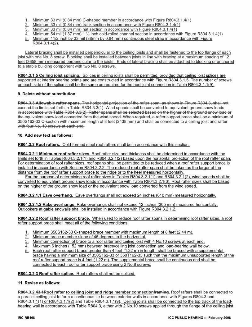
IRC-RB468 ICC PUBLIC HEARING ::: February 2008
1. Minimum 33 mil (0.84 mm) C-shaped member in accordance with Figure R804.3.1.4(1) 2. Minimum 33 mil (0.84 mm) track section in accordance with Figure R804.3.1.4(1) 3. Minimum 33 mil (0.84 mm) hat section in accordance with Figure R804.3.1.4(1) 4. Minimum 54 mil (1.37 mm) 1 ½ inch cold-rolled channel section in accordance with Figure R804.3.1.4(1) 5. Minimum 11/2 inch by 33 mil (38mm by 0.84 mm) continuous steel strap in accordance with Figure
R804.3.1.4(2). Lateral bracing shall be installed perpendicular to the ceiling joists and shall be fastened to the top flange of each
joist with one No. 8 screw. Blocking shall be installed between joists in line with bracing at a maximum spacing of 12 feet (3658 mm) measured perpendicular to the joists. Ends of lateral bracing shall be attached to blocking or anchored to a stable building component with two No. 8 screws. R804.3.1.5 Ceiling joist splicing. Splices in ceiling joists shall be permitted, provided that ceiling joist splices are supported at interior bearing points and are constructed in accordance with Figure R804.3.1.5. The number of screws on each side of the splice shall be the same as required for the heel joint connection in Table R804.3.1.1(9). 9. Delete without substitution: R804.3.3 Allowable rafter spans. The horizontal projection of the rafter span, as shown in Figure R804.3, shall not exceed the limits set forth in Table R804.3.3(1). Wind speeds shall be converted to equivalent ground snow loads in accordance with Table R804.3.3(2). Rafter spans shall be selected based on the higher of the ground snow load or the equivalent snow load converted from the wind speed. When required, a rafter support brace shall be a minimum of 350S162-33 C-section with maximum length of 8 feet (2438 mm) and shall be connected to a ceiling joist and rafter with four No. 10 screws at each end. 10. Add new text as follows: R804.3.2 Roof rafters. Cold-formed steel roof rafters shall be in accordance with this section. R804.3.2.1 Minimum roof rafter sizes. Roof rafter size and thickness shall be determined in accordance with the limits set forth in Tables R804.3.2.1(1) and R804.3.2.1(2) based upon the horizontal projection of the roof rafter span. For determination of roof rafter sizes, roof spans shall be permitted to be reduced when a roof rafter support brace is installed in accordance with Section R804.3.2.2. The reduced roof rafter span shall be taken as the larger of the distance from the roof rafter support brace to the ridge or to the heel measured horizontally.
For the purpose of determining roof rafter sizes in Tables R804.3.2.1(1) and R804.3.2.1(2), wind speeds shall be converted to equivalent ground snow loads in accordance with Table R804.3.2.1(3). Roof rafter sizes shall be based on the higher of the ground snow load or the equivalent snow load converted from the wind speed. R804.3.2.1.1 Eave overhang. Eave overhangs shall not exceed 24 inches (610 mm) measured horizontally. R804.3.2.1.2 Rake overhangs. Rake overhangs shall not exceed 12 inches (305 mm) measured horizontally. Outlookers at gable endwalls shall be installed in accordance with Figure R804.3.2.1.2. R804.3.2.2 Roof rafter support brace. When used to reduce roof rafter spans in determining roof rafter sizes, a roof rafter support brace shall meet all of the following conditions: 1. Minimum 350S162-33 C-shaped brace member with maximum length of 8 feet (2.44 m). 2. Minimum brace member slope of 45 degrees to the horizontal. 3. Minimum connection of brace to a roof rafter and ceiling joist with 4 No.10 screws at each end. 4. Maximum 6 inches (152 mm) between brace/ceiling joist connection and load-bearing wall below. 5. Each roof rafter support brace greater than 4 feet (1.22 m) in length, shall be braced with a supplemental brace having a minimum size of 350S162-33 or 350T162-33 such that the maximum unsupported length of the roof rafter support brace is 4 foot (1.22 m). The supplemental brace shall be continuous and shall be connected to each roof rafter support brace using 2 No.8 screws. R804.3.2.3 Roof rafter splice. Roof rafters shall not be spliced. 11. Revise as follows: R804.3.2.43.1Roof rafter to ceiling joist and ridge member connectionframing. Roof rafters shall be connected to a parallel ceiling joist to form a continuous tie between exterior walls in accordance with Figures R804.3 and R804.3.1.1(1) or R804.3.1.1(2) and Table R804.3.1.1(9). Ceiling joists shall be connected to the top track of the load-bearing wall in accordance with Table R804.3, either with 2 No.10 screws applied through the flange of the ceiling joist

ICC PUBLIC HEARING ::: February 2008 IRC-RB469
or by using a 54 mil (1.37 mm) clip angle with 2 No.10 screws in each leg. Roof rafters shall be connected to a ridge member with a minimum 2-inch by 2-inch (51 mm by 51 mm) clip angle fastened with minimum No. 10 screws to the ridge member in accordance with Figure R804.3.2.43.1 and Table R804.3.2.43.1. The clip angle shall have a minimum steel thickness equivalent to or greater than as the roof rafter thickness member and shall extend the full depth of the roof rafter member to the extent possible. The ridge member shall be fabricated from a C-shaped membersection and a track section, which shall be ofhave a minimum size and steel thickness equivalent to or greater than that of as the adjacent roof rafters and shall be installed in accordance with Figure R804.3.2.43.1.The ridge member shall extend the full depth of the sloped roof rafter cut. 12. Delete without substitution: R804.3.3.2 Roof cantilevers. Roof cantilevers shall not exceed 24 inches (610 mm) in accordance with Figure R804.3. Roof cantilevers shall be supported by a header in accordance with Section R603.6 or shall be supported by the floor framing in accordance with Section R505.3.7 R505.3.6. R804.3.4 Rafter bottom flange bracing. The bottom flanges of steel rafters shall be continuously braced with a minimum 33-mil (0.84 mm) C-section, 33-mil (0.84 mm) track section, or a 11/2-inch by 33-mil (38 mm by 0.84 mm) steel strapping at a maximum spacing of 8 feet (2438 mm) as measured parallel to the rafters. Bracing shall be installed in accordance with Figure R804.3. The C-section, track section, or straps shall be fastened to blocking with at least two No. 8 screws. Blocking or bridging (X-bracing) shall be installed between rafters in-line with the continuous bracing at a maximum spacing of 12 feet (3658 mm) measured perpendicular to the rafters and at the termination of all straps. The ends of continuous bracing shall be fastened to blocking with at least two No. 8 screws. 13. Add new text as follows: R804.3.2.5 Roof rafter bottom flange bracing. The bottom flanges of roof rafters shall be continuously braced, at a maximum spacing of 8 feet (2440 mm) as measured parallel to the roof rafters, with one of the following members:
1. Minimum 33-mil (0.84 mm) C-shaped member 2. Minimum 33-mil (0.84 mm) track section 3. Minimum 11/2-inch by 33-mil (38 mm by 0.84 mm) steel strap
The bracing element shall be fastened to the bottom flange of each roof rafter with one No.8 screw and shall be
fastened to blocking with two No.8 screws. Blocking shall be installed between roof rafters in-line with the continuous bracing at a maximum spacing of 12 feet (3.66 m) measured perpendicular to the roof rafters. The ends of continuous bracing shall be fastened to blocking or anchored to a stable building component with two No.8 screws. R804.3.3 Hip framing. Hip framing shall consist of jack-rafters, hip members, hip support columns and connections in accordance with this section, or shall be in accordance with an approved design. The provisions of this section for hip members and hip support columns shall only apply where the jack rafter slope is greater than or equal to the roof slope. For the purposes of determining member sizes in this section, wind speeds shall be converted to equivalent ground snow load in accordance with Table R804.3.2.1(3). R804.3.3.1 Jack rafters. Jack rafters shall meet the requirements for roof rafters in accordance with Section R804.3.2, except that the requirements in Section R804.3.2.4 shall not apply. R804.3.3.2 Hip members. Hip members shall be fabricated from C-shape members and track section, which shall have minimum sizes determined in accordance with Table R804.3.3.2. The C-shaped member and track section shall be connected at a maximum spacing of 24 inches using No. 10 screws through top and bottom flanges in accordance with Figure R804.3.2.4. The depth of the hip member shall match that of the roof rafters and jack rafters, or shall be based on an approved design for a beam pocket at the corner of the supporting wall. R804.3.3.3 Hip support columns. Hip support columns shall be used to support hip members at the ridge. A hip support column shall consist of a pair of C-shape members, with a minimum size determined in accordance with Table R804.3.3.3. The C-shape members shall be connected at a maximum spacing of 24 inches on center to form a box using minimum 3-inch (76 mm) x 33-mil strap connected to each of the flanges of the C-shape members with 3-No. 10 screws. Hip support columns shall have a continuous load path to the foundation and shall be supported at the ceiling line by an interior wall or by an approved design for a supporting element. R804.3.3.4 Hip framing connections. Hip rafter framing connections shall be installed in accordance with the following:

IRC-RB470 ICC PUBLIC HEARING ::: February 2008
1. Jack rafters shall be connected at the eave to a parallel C-shape blocking member in accordance with Figure R804.3.3.4(1). The C-shape blocking member shall be attached to the supporting wall track with minimum 2- No. 10 screws. 2. Jack rafters shall be connected to a hip member with a minimum 2 inch x 2 inch (50 mm x 50 mm) clip angle fastened with No. 10 screws to the hip member in accordance with Figure R804.3.2.1.2 and Table R804.3.2.4. The clip angle shall have a steel thickness equivalent to or greater than the jack rafter thickness and shall extend the depth of the jack rafter member to the extent possible. 3. The connection of the hip support columns at the ceiling line shall be in accordance with Figure R804.3.3.4(2), with an uplift strap sized in accordance with Table R804.3.3.4(1). 4. The connection of hip support members, ridge members and hip support columns at the ridge shall be in accordance with Figures R804.3.3.4(3) and R804.3.3.4(4) and Table R804.3.3.4(2). 5. The connection of hip members to the wall corner shall be in accordance with Figure R804.3.3.4(5) and Table R804.3.3.4(3). 14. Revise as follows: R804.3.45 Cutting and notching. Flanges and lips of load-bearing cold-formed steel roof framing members shall not be cut or notched. Holes in webs shall be in accordance with Section R804.2. 15. Delete without substitution: R804.3.6 Hole patching. Web holes not conforming to the requirements in Section R804.2 shall be designed in accordance with one of the following:
1. Framing members shall be replaced or designed in accordance with accepted engineering practices when web holes exceed the following size limits: 1.1. The depth of the hole, measured across the web, exceeds 70 percent of the flat width of the web; or, 1.2. The length of the hole, measured along the web, exceeds 10 inches (254 mm) or the depth of the
web, whichever is greater. 2. Web holes not exceeding the dimensional requirements in Section R804.3.6, Item 1 shall be patched with a
solid steel plate, stud section, or track section in accordance with Figure R804.3.6. The steel patch shall be of a minimum thickness as the receiving member and shall extend at least 1 inch (25 mm) beyond all edges of the hole. The steel patch shall be fastened to the web of the receiving member with No. 8 screws spaced no greater than 1 inch (25 mm) center- to-center along the edges of the patch with minimum edge distance of 1/2 inch (13 mm).
R804.3.7 Splicing. Rafters and other structural members, except ceiling joists, shall not be spliced. Splices in ceiling joists shall only be permitted at interior bearing points and shall be constructed in accordance with Figure R804.3.7(1). Spliced ceiling joists shall be connected with the same number and size of screws on connection. Splicing of tracks shall conform to Figure R804.3.7(2). R804.3.8 Bearing stiffener. A bearing stiffener shall be fabricated from a minimum 33-mil (0.84 mm) C-section or track section. Each stiffener shall be fastened to the web of the ceiling joist with a minimum of four No. 8 screws equally spaced as shown in Figure R804.3.8. Stiffeners shall extend across the full depth of the web and shall be installed on either side of the web. 16. Revise as follows: R804.3.59 Headers. Roof-ceiling framing above wall openings shall be supported on headers. The allowable spans for headers in load bearing walls shall not exceed the values set forth in Section R603.6 and Tables R603.6(1) through R603.6(24). R804.3.610 Framing of openings in roofs and ceilings. Openings in roofs and ceilings framing shall be framed with headers and trimmers joists.between ceiling joists or rafters. Header joist spans shall not exceed 4 feet (1219 mm) in length. Header and trimmer joists shall be fabricated from joist and track members having a minimum size and thickness at least equivalent to the adjacent ceiling joists or roof rafters and shall be installed sections, which shall be of a minimum size and thickness in accordance with Figures R804.3.10(1) R804.3.6(1) and R804.3.10(2) R804.3.6(2). Each header joist shall be connected to a trimmer joists with a minimum of four 2-inch by 2-inch (51 by 51 mm) clip angles. Each clip angle shall be fastened to both the header and trimmer joists with four No. 8 screws, evenly spaced, through each leg of the clip angle. The clip angles shall have a steel thickness not less than that of the floor ceiling joist or roof rafter. Each track section for a built-up header or trimmer joist shall extend the full length of the joist (continuous).

ICC PUBLIC HEARING ::: February 2008 IRC-RB471
17. Add new text as follows: R804.3.7 Roof trusses. Cold-formed steel trusses shall be designed and installed in accordance with AISI S100, Section D4. Trusses shall be connected to the top track of the load-bearing wall in accordance with Table R804.3, either with 2 No.10 screws applied through the flange of the truss or by using a 54 mil (1.37 mm) clip angle with 2 No.10 screws in each leg. R804.3.8 Ceiling and roof diaphragms. Ceiling and roof diaphragms shall be in accordance with this section. R804.3.8.1 At gable endwalls a ceiling diaphragm shall be provided by attaching a minimum 1/2-inch (13 mm) gypsum board in accordance with Tables R804.3.8(1) and R804.3.8(2) or a minimum 3/8-inch (9.5 mm) wood structural panel sheathing, which complies with Section R803, in accordance with Table R804.6(3) to the bottom of ceiling joists or roof trusses and connected to wall framing in accordance with Figures R804.3.8(1) and R804.3.8(2), unless studs are designed as full height without bracing at the ceiling. Flat blocking shall consist of C-shape or track section with a minimum thickness of 33 mils (0.84 mm). The ceiling diaphragm shall be secured with screws spaced at a maximum 6” o.c. at panel edges and a maximum 12” o.c. in the field. The required lengths in Tables R804.3.8(1) and R804.3.8(2) for gypsum board sheathed ceiling diaphragms shall be permitted to be multiplied by 0.35 if all panel edges are blocked. The required lengths in Tables R804.3.8(1) and R804.3.8(2) for gypsum board sheathed ceiling diaphragms shall be permitted to be multiplied by 0.9 if all panel edges are secured with screws spaced at 4” o.c. R804.3.8.2 Roof diaphragm. A roof diaphragm shall be provided by attaching a minimum of 3/8 inch (9.5 mm) wood structural panel, which complies with Section R803, to roof rafters or truss top chords in accordance with Table R804.3. Buildings with 3-1 or larger plan aspect ratio and with roof rafters slope (pitch) of 9:12 or larger shall have the roof rafters and ceiling joists blocked in accordance with Figure R804.3.8(3). 18. Revise as follows: R804.3.9R804.4 Roof tie-down. Roof assemblies subject to wind uplift pressures of 20 pounds per square foot (0.96 kN/m2) or greater, as established in Table R301.2(2), shall have rafter-to-bearing wall ties provided in accordance with Table R802.11.
TABLE R804.2(2) MINIMUM THICKNESS OF COLD-FORMED STEEL MEMBERS
DESIGNATION THICKNESS (mils)
MINIMUM BASE STEEL UNCOATED THICKNESS (inches)
REFERENCE GAGE NUMBER
33 0.03293 20 43 0.04283 18 54 0.05384 16 68 0.06778 14 97 0.0966
For SI: 1 inch = 25.4 mm, 1 mil = 0.0254 mm.
TABLE R804.3 ROOF FRAMING FASTENING SCHEDULE
(No change to table entries) a. Screws shall be applied through the flanges of the truss or ceiling joist or a 54 mil clip angle shall be used with two
No. 10 screws in each leg. See Section R804.3.84 for additional requirements to resist uplift forces. b. (No change)
TABLE R804.3.1.1(1) CEILING JOIST SPANS
SINGLE SPANS WITH BEARING STIFFENERS 10 lb per sq ft LIVE LOAD (NO ATTIC STORAGE)a, b, c 33 ksi STEEL
(Portion of table and footnotes not shown do not change)
IRC-RB472 ICC PUBLIC HEARING ::: February 2008
TABLE R804.3.1.1(2) CEILING JOIST SPANS
TWO EQUAL SPANS WITH BEARING STIFFENERS 10 lb per sq ft LIVE LOAD (NO ATTIC STORAGE)a, b, c 33 ksi STEEL
(Portion of table and footnotes not shown do not change)
TABLE R804.3.1.1(3) CEILING JOIST SPANS
SINGLE SPANS WITH BEARING STIFFENERS 20 lb per sq ft LIVE LOAD (LIMITED ATTIC STORAGE)a, b, c 33 ksi STEEL
(Portion of table and footnotes not shown do not change)
TABLE R804.3.1.1(4)
CEILING JOIST SPANS TWO EQUAL SPANS WITH BEARING STIFFENERS
20 lb per sq ft LIVE LOAD (LIMITED ATTIC STORAGE)a, b, c 33 ksi STEEL
(Portion of table and footnotes not shown do not change)
TABLE R804.3.1.1(5) CEILING JOIST SPANS
SINGLE SPANS WITHOUT BEARING STIFFENERS 10 lb per sq ft LIVE LOAD (NO ATTIC STORAGE)a, b 33 ksi STEEL
(Portion of table and footnotes not shown do not change)
TABLE R804.3.1.1(6) CEILING JOIST SPANS
TWO EQUAL SPANS WITHOUT BEARING STIFFENERS 10 lb per sq ft LIVE LOAD (NO ATTIC STORAGE)a, b 33 ksi STEEL
(Portion of table and footnotes not shown do not change)
TABLE R804.3.1.1(7)
CEILING JOIST SPANS SINGLE SPANS WITHOUT BEARING STIFFENERS
20 lb per sq ft LIVE LOAD (LIMITED ATTIC STORAGE)a, b 33 ksi STEEL (Portion of table and footnotes not shown do not change)
TABLE R804.3.1.1(8)
CEILING JOIST SPANS TWO EQUAL SPANS WITHOUT BEARING STIFFENERS
20 lb per sq ft LIVE LOAD (LIMITED ATTIC STORAGE)a, b 33 ksi STEEL (Portion of table and footnotes not shown do not change)
TABLE R804.3.1.1(9)
NUMBER OF SCREWS REQUIRED FOR CEILING JOIST TO ROOF RAFTER CONNECTION (Portion of table and footnotes not shown do not change)
19. Delete Table R804.3.3(1) and substitute as follows:
TABLE R804.3.3(1) ALLOWABLE HORIZONTAL RAFTER SPANS 33 ksi STEEL

ICC PUBLIC HEARING ::: February 2008 IRC-RB473
TABLE R804.3.2.1(1) ROOF RAFTER SPANS a,b,c
33 ksi STEEL
ALLOWABLE SPAN MEASURED HORIZONTALLY (feet-Inches)
Ground Snow Load
20 psf 30 psf 50 psf 70 psf
Rafter Spacing (in.)
MEMBER DESIGNATION
16 24 16 24 16 24 16 24
550S162-33 14'-0" 11'-6" 11'-11" 9'-7" 9'-6" 7'-9" 8'-2" 6'-8"
550S162-43 16'-8" 13'-11" 14'-5" 11'-9" 11'-6" 9'-5" 9'-10 8'-0"
550S162-54 17'-11" 15'-7" 15'-7" 13'-3" 12'-11" 10'-7" 11'-1" 9'-1"
550S162-68 19'-2" 16'-9" 16'-9" 14'-7" 14'-1" 11'-10" 12'-6" 10'-2"
550S162-97 21'-3" 18'-6" 18'-6" 16'-2" 15'-8" 13'-8" 14'-0" 12'-2"
800S162-33 16'-5" 13'-5" 13'-11" 11'-4" 11'-1" 8'-2" 9'-0" 6'-0"
800S162-43 19'-9" 16'-1" 16'-8" 13'-7" 13'-4" 10'-10" 11'-5" 9'-4"
800S162-54 22'-8" 18'-6" 19'-2" 15'-8" 15'-4" 12'-6" 13'-1" 10'-8"
800S162-68 25'-10" 21'-2" 21'-11" 17'-10" 17'-6" 14'-4" 15'-0" 12'-3"
800S162-97 21'-3" 18'-6" 18'-6" 16'-2" 15'-8" 13'-8" 14'-0" 12'-2"
1000S162-43 22'-3" 18'-2" 18'-9" 15'-8" 15'-0" 12'-3" 12'-10" 10'-6"
1000S162-54 25'-8" 20'-11" 21'-8" 17'-9" 17'-4" 14'-2" 14'-10" 12'-1"
1000S162-68 29'-7" 24'-2" 25'-0" 20'-5" 20'-0" 16'-4" 17'-2" 14'-0"
1000S162-97 34'-8" 30'-4" 30'-4" 25'-10" 25'-3" 20'-8" 21'-8" 17'-8"
1200S162-54 28'-3" 23'-1" 23'-11" 19'-7" 19'-2" 15'-7" 16'-5" 13'-5"
1200S162-68 32'-10" 26'-10" 27'-9" 22'-8" 22'-2" 18'-1" 19'-0" 15'-6"
1200S162-97 40'-6" 33'-5" 34'-6" 28'-3" 27'-8" 22'-7" 23'-8" 19'-4"
For SI: 1 inch = 25.4 mm, 1 foot = 304.8 mm, 1 pound per square foot = 0.0479 kPa. a. Table provides maximum horizontal rafter spans in feet and inches for slopes between 3:12 and 12:12. b. Deflection criterion: L/240 for live loads and L/180 for total loads. c. Roof dead load = 12 psf.

IRC-RB474 ICC PUBLIC HEARING ::: February 2008
20. Add new tables as follows: TABLE R804.3.2.1(2)
ROOF RAFTER SPANS a,b,c 50 ksi STEEL
ALLOWABLE SPAN MEASURED HORIZONTALLY (Feet-Inches)
Equivalent Ground Snow Load
20 psf 30 psf 50 psf 70 psf
Roof Rafter Spacing (in.)
MEMBER DESIGNATION
16 24 16 24 16 24 16 24
550S162-33 15'-4" 12'-11" 13'-4" 10'-11" 10'-9" 8'-9" 9'-2" 7'-6"
550S162-43 16'-8" 14'-7" 14'-7" 12'-9" 12'-3" 10'-6" 11'-0" 9'-0"
550S162-54 17'-11" 15'-7" 15'-7" 13'-8" 13'-2" 11'-6" 11'-9" 10'-3"
550S162-68 19'-2" 16'-9" 16'-9" 14'-7" 14'-1" 12'-4" 12'-7" 11'-0"
550S162-97 21'-3" 18'-6" 18'-6" 16'-2" 15'-8" 13'-8" 14'-0" 12'-3"
800S162-33 18'-10" 15'-5" 15'-11" 12'-9" 12'-3" 8'-2" 9'-0" 6'-0"
800S162-43 22'-3" 18'-2" 18'-10" 15'-5" 15'-1" 12'-3" 12'-11" 10'-6"
800S162-54 24'-2" 21'-1" 21'-1" 18'-5" 17'-10" 14'-8" 15'-5" 12'-7"
800S162-68 25'-11" 22'-8" 22'-8" 19'-9" 19'-1" 16'-8" 17'-1" 14'-9"
800S162-97 28'-10 25'-2" 25'-2" 22'-0" 21'-2" 18'-6" 19'-0" 16'-7"
1000S162-43 25'-2" 20'-7" 21'-4" 17'-5" 17'-0" 13'-11" 14'-7" 10'-7"
1000S162-54 29'-0" 24'-6" 25'-4" 20'-9" 20'-3" 16'-7" 17'-5" 14'-2"
1000S162-68 31'-2" 27'-3" 27'-3" 23'-9" 23'-0" 19'-6" 20'-6" 16'-8"
1000S162-97 34'-8" 30'-4" 30'-4" 26'-5" 25'-7" 22'-4" 22'-10" 20'-0"
1200S162-54 33'-2" 27'-1" 28'-1" 22'-11" 22'-5" 18'-4" 19'-3" 15'-8"
1200S162-68 36'-4" 31'-9" 31'-9" 27'-0" 26'-5" 21'-6" 22'-6" 18'-6"
1200S162-97 40'-6" 35'-4" 35'-4" 30'-11" 29'-10" 26'-1" 26'-8" 23'-1"
For SI: 1 inch = 25.4 mm, 1 foot = 304.8 mm, 1 pound per square foot = 0.0479 kPa. a. Table provides maximum horizontal rafter spans in feet and inches for slopes between 3:12 and 12:12. b. Deflection criterion: L/240 for live loads and L/180 for total loads. c. Roof dead load = 12 psf. 21. Revise as follows:
TABLE R804.3.3(2)R804.3.2.1(3) BASIC WIND SPEED TO EQUIVALENT SNOW LOAD CONVERSION
(Portions of table shown do not change)
TABLE R804.3.2.43.1 NUMBER OF SCREWS REQUIRED AT EACH LEG OF CLIP ANGLE FOR RAFTER TO RIDGE MEMBER CONNECTION a
SCREWS REQUIRED AT EACH LEG OF CLIP ANGLE FOR HIP RAFTER TO HIP MEMBER OR ROOF RAFTER TO RIDGE MEMBER CONNECTION a
(Portions of table shown do not change)

ICC PUBLIC HEARING ::: February 2008 IRC-RB475
22. Add new tables as follows:
TABLE 804.3.3.2 HIP MEMBER SIZES
33 ksi STEEL
HIP MEMBER DESIGNATION a
Equivalent Ground Snow Load (psf) BUILDING
WIDTH (feet) 0 to 20 21 to 30 31 to 50 51 to 70
24 800S162-68 800T150-68
800S162-68 800T150-68
800S162-97 800T150-97
1000S162-97 1000T150-97
28 1000S162-68 1000T150-68
1000S162-68 1000T150-68
1000S162-97 1000T150-97
1200S162-97 1200T150-97
32 1000S162-97 1000T150-97
1000S162-97 1000T150-97
1200S162-97 1200T150-97 -
36 1200S162-97 1200T150-97 - - -
40 - - - -
For SI: 1 foot = 305 mm, 1 pound per square foot = 0.0479 kPa a. The web depth of the roof rafters and jack rafters are to match at the hip or shall be installed in accordance with an
approved design.
TABLE 804.3.3.3 HIP SUPPORT COLUMN SIZES
HIP SUPPORT COLUMN DESIGNATION a,b
Equivalent Ground Snow Load (psf) BUILDING
WIDTH (feet) 0 to 20 21 to 30 31 to 50 51 to 70
24 2-350S162-33 2-350S162-33 2-350S162-43 2-350S162-54
28 2-350S162-54 2-550S162-54 2-550S162-68 2-550S162-68
32 2-550S162-68 2-550S162-68 2-550S162-97 -
36 2-550S162-97 - - -
40 - - - -
For SI: 1 foot = 305 mm, 1 pound per square foot = 0.0479 kPa. a. Box shape column only in accordance with Figure R804.3.3.4(2) b. 33 ksi Steel for 33 and 43 mil material. 50 ksi Steel for thicker material.

IRC-RB476 ICC PUBLIC HEARING ::: February 2008
TABLE 804.3.3.4(1) UPLIFT STRAP CONNECTION REQUIREMENTS
HIP SUPPORT COLUMN AT CEILING LINE
BASIC WIND SPEED (MPH) 85 100 110 - - - 85 - 100 110
BUILDING WIDTH (feet)
Number of No. 10 Screws in Each End of Each 3 inch by 54-mil Steel Strap a,b,c
24 3 4 4 6 7 28 4 6 6 8 10 32 5 8 8 11 13 36 7 10 11 14 17 40 - - - - -
For SI: 1 foot = 305 mm, 1 pound per square foot = 0.479 kPa a. Two straps are required, one each side of the column. b. Space screws at ¾ inches on-center and provide ¾ inch end distance. c. 50 ksi Steel strap.
TABLE R804.3.3.4(2) CONNECTION REQUIREMENTS
HIP MEMBER TO HIP SUPPORT COLUMN
NUMBER OF No.10 SCREWS IN EACH FRAMING ANGLE A,B,C
Equivalent Ground Snow Load (psf) BUILDNG WIDTH (feet)
0 to 20 21 to 30 31 to 50 51 to 70
24 10 10 10 12
28 10 10 14 18
32 10 12 -
36 14 - - -
40 - - - -
For SI: 1 foot = 305 mm, 1 pound per square foot = 0.479 kPa. a. Screws to be divided equally between the connection to the hip member and the column. Refer to
figures R804.3.3.4(3) and R804.3.3.4(4) b. The number of screws required in each framing angle is not to be less than shown in Table R804.5.4(1) c. 50 ski Steel from the framing angle.

ICC PUBLIC HEARING ::: February 2008 IRC-RB477
TABLE 804.3.3.4(3) UPLIFT STRAP CONNECTION REQUIREMENTS
HIP MEMBER TO WALL
BASIC WIND SPEED (MPH) 85 100 110 - - - 85 - 100 110
BUILDING WIDTH (feet)
Number of No. 10 Screws in Each End of Each 3 inch by 54-mil Steel Strap a,b,c
24 2 2 3 3 4 28 2 3 3 4 5 32 3 4 4 6 7 36 3 5 5 7 8 40 - - - - -
For SI: 1 foot = 305 mm, 1 pound per square foot = 0.479 kPa a. Two straps are required, one each side of the column. b. Space screws at ¾ inches on-center and provide ¾ inch end distance. c. 50 ksi Steel strap.
TABLE R804.3.8(1) REQUIRED LENGTHS FOR CEILING DIAPHRAGMS AT GABLE ENDWALLS
GYPSUM BOARD SHEATHED CEILING HEIGHT = 8 ft a,b,c,d,e,f
BASIC WIND SPEED (mph) Exposure A/B 85 100 110 - - Exposure C - 85 - 100 110
Roof Pitch Building Endwall Width (ft) Minimum Diaphragm Length (ft) 24 - 28 14 20 22 28 32 28 - 32 16 22 28 32 38 32 - 36 20 26 32 38 44
3:12 to
6:12 36 - 40 22 30 36 44 50 24 - 28 16 22 26 32 36 28 - 32 20 26 32 38 44 32 - 36 22 32 38 44 52
6:12 to
9:12 36 - 40 26 36 44 52 60 24 - 28 18 26 30 36 42 28 - 32 22 30 36 42 50 32 - 36 26 36 42 50 60
9:12 to
12:12 36 - 40 30 42 50 60 70
For SI: 1 inch = 25.4 mm, 1 psf = 0.0479 kN/m2, 1 mph = 1.61 km/hr, 1 foot = 305 mm a. Ceiling diaphragm is composed of 1/2" gypsum board (min. thickness) secured with screws spaced at 6” o.c.
at panel edges and 12” o.c. in field. Use No. 8 screws (min.) when framing members have a designation thickness of 54 mils or less and No. 10 screws (min.) when framing members have a designation thickness greater than 54 mils.
b. Maximum aspect ratio (length/width) of diaphragms is 2:1. c. Building width is in the direction of horizontal framing members supported by the wall studs. d. Required diaphragm lengths are to be provided at each end of the structure. e. Required diaphragm lengths are permitted to be multiplied by 0.35 if all panel edges are blocked. f. Required diaphragm lengths are permitted to be multiplied by 0.9 if all panel edges are secured with screws
spaced at 4” o.c.

IRC-RB478 ICC PUBLIC HEARING ::: February 2008
TABLE R804.3.8(2) REQUIRED LENGTHS FOR CEILING DIAPHRAGMS AT GABLE ENDWALLS
GYPSUM BOARD SHEATHED CEILING HEIGHT = 9 or 10 ft a,b,c,d,e,f
BASIC WIND SPEED (mph) Exposure A/B 85 100 110 - - Exposure C - 85 - 100 110
Roof Pitch Building Endwall Width (ft) Minimum Diaphragm Length (ft) 24 - 28 16 22 26 32 38 28 - 32 20 26 32 38 44 32 - 36 22 30 36 44 50
3:12 to
6:12 36 - 40 26 36 42 50 58 24 - 28 18 26 30 36 42 28 - 32 22 30 36 42 50 32 - 36 26 36 42 50 58
6:12 to
9:12 36 - 40 30 42 48 58 68 24 - 28 20 28 34 40 46 28 - 32 24 34 40 48 56 32 - 36 28 40 48 56 66
9:12 to
12:12 36 - 40 34 46 56 66 78
For SI: 1 inch = 25.4 mm, 1 psf = 0.0479 kN/m2, 1 mph = 1.61 km/hr, 1 foot = 305 mm a. Ceiling diaphragm is composed of 1/2" gypsum board (min. thickness) secured with screws spaced at 6” o.c. at
panel edges and 12” o.c. in field. Use No. 8 screws (min.) when framing members have a designation thickness of 54 mils or less and No. 10 screws (min.) when framing members have a designation thickness greater than 54 mils.
b. Maximum aspect ratio (length/width) of diaphragms is 2:1. c. Building width is in the direction of horizontal framing members supported by the wall studs. d. Required diaphragm lengths are to be provided at each end of the structure. e. Required diaphragm lengths are permitted to be multiplied by 0.35 if all panel edges are blocked. f. Required diaphragm lengths are permitted to be multiplied by 0.9 if all panel edges are secured with screws
spaced at 4” o.c.
TABLE R804.3.8(3) REQUIRED LENGTHS FOR CEILING DIAPHRAGMS AT GABLE ENDWALLS
WOOD STRUCTURAL PANEL SHEATHED CEILING HEIGHT = 8, 9 OR 10 ft a,b,c,d,e,f
Basic Wind Speed (mph) Exposure A/B 85 100 110 - - Exposure C - 85 - 100 110
Roof Pitch Building Endwall Width (ft) Minimum Diaphragm Length (ft) 24 - 28 10 10 10 10 10 28 - 32 12 12 12 12 12 32 - 36 12 12 12 12 12
3:12 to
6:12 36 - 40 14 14 14 14 14 24 - 28 10 10 10 10 10 28 - 32 12 12 12 12 12 32 - 36 12 12 12 12 12
6:12 to
9:12 36 - 40 14 14 14 14 14 24 - 28 10 10 10 10 10 28 - 32 12 12 12 12 12 32 - 36 12 12 12 12 12
9:12 to
12:12 36 - 40 14 14 14 14 14
For SI: 1 inch = 25.4 mm, 1 psf = 0.0479 kN/m2, 1 mph = 1.61 km/hr, 1 foot = 305 mm a. Ceiling diaphragm is composed of 3/8" wood structural panel sheathing (min. thickness) secured with screws
spaced at 6” o.c. at panel edges and in field. Use No. 8 screws (min.) when framing members have a designation thickness of 54 mils or less and No. 10 screws (min.) when framing members have a designation thickness greater than 54 mils.
b. Maximum aspect ratio (length/width) of diaphragms is 3:1. c. Building width is in the direction of horizontal framing members supported by the wall studs. d. Required diaphragm lengths are to be provided at each end of the structure.

ICC PUBLIC HEARING ::: February 2008 IRC-RB479
23. Add new figure as follows:
FIGURE R804.1.2 IN-LINE FRAMING
24. Revise as follows:
FIGURE R804.2(1) C-SHAPED SECTION
(No change to figure)
FIGURE R804.2.5.12(3) WEB HOLES
(No change to figure)

IRC-RB480 ICC PUBLIC HEARING ::: February 2008
25. Add new figure as follows:
FIGURE R804.2.5.3 WEB HOLE PATCH

ICC PUBLIC HEARING ::: February 2008 IRC-RB481
26. Revise as follows:
FIGURE R804.3 STEEL ROOF CONSTRUCTION

IRC-RB482 ICC PUBLIC HEARING ::: February 2008
27. Delete existing Figure R804.3.1(1) and replace as follows:
FIGURE R804.3.1.1(1) JOIST TO RAFTER CONNECTION

ICC PUBLIC HEARING ::: February 2008 IRC-RB483
28. Add new figures as follows:
FIGURE R804.3.1.1(2) BEARING STIFFENER
FIGURE R804.3.1.4(1) CEILING JOIST TOP FLANGE BRACING WITH C-SHAPE, TRACK OR COLD-ROLLED CHANNEL

IRC-RB484 ICC PUBLIC HEARING ::: February 2008
FIGURE R804.3.1.4(2) CEILING JOIST TOP FLANGE BRACING WITH CONTINUOUS STEEL STRAP AND BLOCKING
FIGURE R804.3.1.5
SPLICED CEILING JOISTS

ICC PUBLIC HEARING ::: February 2008 IRC-RB485
FIGURE R804.3.2.1.2
GABLE ENDWALL OVERHANG DETAILS
#8 SCREWS @ 6" O.C.1'-0" MIN1'-0" MAX
#8 SCREWS @ 6" O.C.
GABLE END WALL STUDS
4 - #8 SCREWS (OUTLOOKER
TO WALL TRACK)
350S162-33 BLOCKING BETWEEN OUTLOOKERS W/#8 SCREWS @ 6" O.C.
TO WALL TRACK (MIN. 3 SCREWS EACH)
WALL SHEATHING REF. TABLE E3-11 (AISI, 2002) FOR
ATTACHMENT 350S162-33 (W/0 WEB HOLES) OUTLOOK RAFTERS. ALIGN WITH EACH GABLE WALL STUD
ROOF RAFTER
CLIP ANGLE W/2 - #8 SCREWS EACH LEG
OPTION #1:
OPTION #2:
WALL SHEATHING
GABLE END WALL STUDS
1'-0" MAX (SEE NOTE) 1'-0" MIN
#8 SCREWS @ 6" O.C.
350S162-33 OUTLOOKERS @ 2'-0" O.C. W/ CONTINUOUS
TRACK EACH END 2 - #8 SCREWS TO EACH STUD ROOF RAFTER
NOTE: ROOF SHEATHING JOINTS PARALLEL TO THE GABLE ENDWALL ARE NOT PERMITTED IN THIS REGION UNLESS AN APPROVED TENSION TIE IS PROVIDED.

IRC-RB486 ICC PUBLIC HEARING ::: February 2008
29. Revise as follows:
FIGURE R804.3.2.43.1 HIP MEMBER OR RIDGE BOARD MEMBER CONNECTION
30. Add new figures as follows:
FIGURE R804.3.3.4(1) JACK RAFTER CONNECTION AT EAVE
HIP MEMBER OR RIDGE MEMBER: C-SHAPE INSIDE A TRACK SECTION FASTENED WITH NO. 10 SCREWS @ 24” O.C. THROUGH TOP & BOTTOM FLANGES.
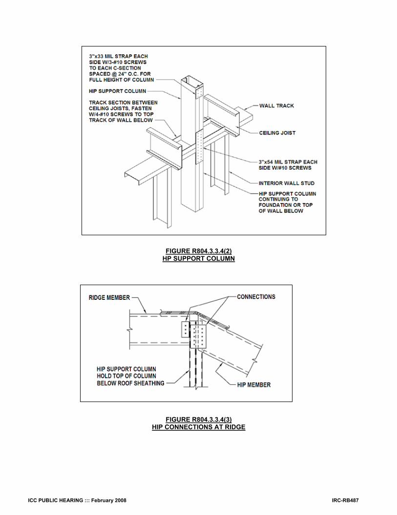
ICC PUBLIC HEARING ::: February 2008 IRC-RB487
FIGURE R804.3.3.4(2) HP SUPPORT COLUMN
FIGURE R804.3.3.4(3) HIP CONNECTIONS AT RIDGE

IRC-RB488 ICC PUBLIC HEARING ::: February 2008
FIGURE R804.3.3.4(4)
HIP CONNECTIONS AT RIDGE AND BOX COLUMN

ICC PUBLIC HEARING ::: February 2008 IRC-RB489
FIGURE R804.3.3.4(5) HIP MEMBER CONNECTION AT WALL CORNER
31. Delete figures without substitution:
FIGURE R804.3.6 HOLE PATCHING
FIGURE R804.3.7(1)
SPLICED CEILING JOIST
FIGURE R804.3.7(2) TRACK SPLICE
FIGURE R804.3.8
BEARING STIFFENER 32. Revise as follows:
FIGURE R804.3.10(1) R804.3.6(1) ROOF OR CEILING OPENING
(No change to figure)
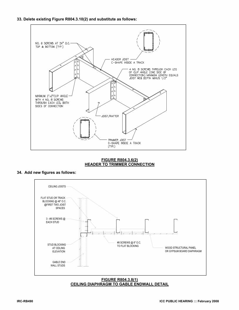
IRC-RB490 ICC PUBLIC HEARING ::: February 2008
33. Delete existing Figure R804.3.10(2) and substitute as follows:
FIGURE R804.3.6(2) HEADER TO TRIMMER CONNECTION
34. Add new figures as follows:
FIGURE R804.3.8(1) CEILING DIAPHRAGM TO GABLE ENDWALL DETAIL
CEILING JOISTS
WOOD STRUCTURAL PANEL OR GYPSUM BOARD DIAPHRAGM
GABLE END WALL STUDS
FLAT STUD OR TRACK BLOCKING @ 48" O.C.
@FIRST TWO JOIST SPACES
STUD BLOCKING AT CEILING ELEVATION
#8 SCREWS @ 6" O.C.TO FLAT BLOCKING
3 - #8 SCREWS @ EACH STUD
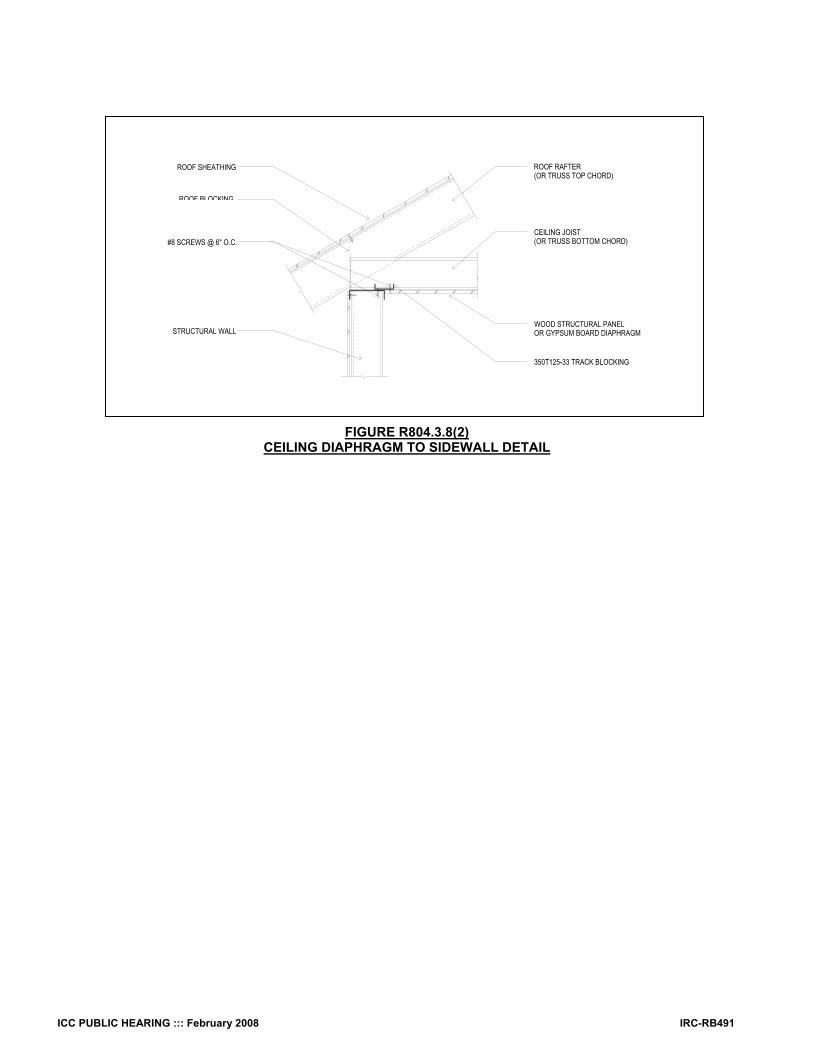
ICC PUBLIC HEARING ::: February 2008 IRC-RB491
FIGURE R804.3.8(2) CEILING DIAPHRAGM TO SIDEWALL DETAIL
WOOD STRUCTURAL PANEL OR GYPSUM BOARD DIAPHRAGM
ROOF BLOCKING
ROOF SHEATHING
350T125-33 TRACK BLOCKING
STRUCTURAL WALL
#8 SCREWS @ 6" O.C. CEILING JOIST
(OR TRUSS BOTTOM CHORD)
ROOF RAFTER (OR TRUSS TOP CHORD)

IRC-RB492 ICC PUBLIC HEARING ::: February 2008
FIGURE R804.6(3)
ROOF BLOCKING DETAIL 35. Add standards to Chapter 43 as follows: AISI
S100-07 North American Specification for the Design of Cold-Formed Steel Structural Members ASTM
C 1513-04 Standard Specification for Steel Tapping Screws for Cold-Formed Steel Framing Connections
Reason: This code change updates the prescriptive requirements of International Residential Code, Section R804, to reflect the 2007 edition of AISI S230, Standard for Cold-Formed Steel Framing -- Prescriptive Method for One- and Two-Family Dwellings. The following substantive changes have been made to Section 804 (Steel Roof Framing): PART 1: SECTION 804 Section R804.1.1: The 2007 edition of AISI S230 (Standard for Cold-Formed Steel Framing – Prescriptive Method for One and Two Family Dwellings) increases the allowable number of stories from two to three stories. This modification is intended to coordinate with AISI S230.
ICC PUBLIC HEARING ::: February 2008 IRC-RB493
Section R804.1.2: The 2007 edition of AISI S230 references the 2007 edition of AISI S200 (North American Standard for Cold-Formed Steel Framing—General Provisions) which has revised the in-line framing tolerance to account for the special case of the bearing stiffener located on the back-side of the joist. This was based on research at the University of Waterloo (Reference: Fox, S.R. (2003), “The Strength of Stiffened CFS Floor Joist Assemblies with Offset Loading,” American Iron and Steel Institute, Washington, D.C.)
Section R804.2: Table R804.2(2) has been corrected to reflect industry standardized thicknesses for structural members. Additionally, a line has been added for 97 mils, since it is used extensively throughout the IRC. The column on Reference Gage Number has been deleted, since gage is no longer used by industry in referencing structural members. Finally, the topic of holes has been relocated to a new Section R804.2.5 on web holes, web hole reinforcement, and web hole patching. Accordingly, the associated Figure R804.2(3) has been renumbered to Figure R804.2.5.1, with no other changes to the figure.
Section R804.2.1: This section has been modified to coordinate with the 2007 edition of AISI S230, which now recognizes ASTM A 1003 as the primary standard for cold-formed steel light frame construction (via a reference to AISI S200). References to the ASTM A 1003 grades have been corrected to specify Structural Type H. Further, references to Grades 37 and 40 have been deleted, since these grades are not used by the IRC. Finally, the references to ASTM A 653 and ASTM A792 have been retained, since AISI S230 still considers them deemed-to-comply with ASTM A 1003. However, reference to ASTM A875 has been deleted, since it is no longer used in the construction marketplace.
Section R804.2.2: This section has been modified to reflect the change in terminology in Table R804.2(2) from “uncoated steel thickness” to “base steel thickness.”
Section R804.2.3: This section has been modified to coordinate with the 2007 edition of AISI S230, which now recognizes ASTM A1003 as the primary standard for cold-formed steel light frame construction (via a reference to AISI S200). The reference to ASTM A875 has been deleted, since it is no longer used in the construction marketplace.
Section R804.2.4: This section has been modified to coordinate with the 2007 edition of AISI S230, which now recognizes ASTM C1513 (via a reference to AISI S200) in lieu of SAE J78. ASTM C1513 is the more appropriate consensus standard, which continues to charge SAE J78. The reference to ASTM B 633 has been deleted in favor of the substituted language from AISI S230.
Section R804.2.5.1: Section R804.2.5.1 has been created using existing IRC Section 804.2 in order to improve the clarity and usability of the code by locating all requirements concerning web holes and web hole adjustments in one central location. In addition, Figure R804.2(3) has been renumbered as Figure R804.2.5.1, with no other changes to the figure, as part of the coordination effort.
Section R804.2.5.2: New to the 2007 edition of AISI S230, this language permits the reinforcing of web holes, thus allowing the utility to remain, as long as the finished web hole meets the requirements of this subsection and that of Section R804.2.5.1. The provisions are based on engineering judgment and have been confirmed by preliminary testing.
Section R804.2.5.3: This language has been relocated from Section R804.3.6 in order to improve the clarity and usability of the code. Modifications have been made to the charging language to reflect the fact that the user now has the choice to reinforce non-conforming holes, patch non-conforming holes, or design non-conforming holes with accepted engineering practice per Section R804.2.5.1. Additionally, Figure R804.2.5.3 has been added as an update to the old Figure R804.3.6, in order to coordinate with AISI S230-07.
Section R804.3: This section has been modified substantially to reflect the latest provisions from AISI S230-07. Section R804.3.1: This section on ceiling joists has been modified to improve its clarity and reflect the latest provisions from AISI S230-07. In
particular, the topics of minimum ceiling joist size, ceiling joist bearing stiffeners, ceiling joist bottom flange bracing, ceiling joist top flange bracing and ceiling joist splicing have been relocated into their own individual sections to highlight the different requirements.
Section R804.3.2: This section on roof rafters has been modified to improve its clarity and reflect the latest provisions from AISI S230-07. In particular, the topics of minimum roof rafter size, roof rafter support brace, roof rafter splice, roof rafter to ceiling joist and ridge member connection, and roof rafter bottom flange bracing have been relocated into their own individual sections to highlight the different requirements.
Section R804.3.2.1: New sub-sections on eave overhangs and rake overhangs have been added. The section on rake overhangs addresses the lack of information on this subject in previous editions of the IRC and coordinates with AISI S230-07. In addition Figure R804.3.2.1.2 has been added to supplement this provision. Accordingly, Section R804.3.3.2 on roof cantilevers has been recommended for deletion.
Section R804.3.3: Cold-formed steel hip framing has been added to this section to cover a topic not previously addressed in the IRC. Although this topic is considered common practice and has been available to users through the AISI Prescriptive method in the past, the industry felt it time to integrate these provisions into the IRC to complete the prescriptive requirements in the roofing section. Along with provisions, this proposal also includes tables for framing member and fastening requirements, and includes figures demonstrating the various connections details.
Section R804.3.6: This section on hole patching has been relocated to new section R804.2.5.3 with all other provisions for web holes in framing members. As a result of this change, subsequent sections have been renumbered for coordination. In addition the associated figures and tables have also been renumbered for coordination.
Section R804.3.7: This section on splicing has been split and relocated to the applicable sections on ceiling joists and roof rafters. As a result of this change, subsequent sections have been renumbered for coordination.
Section R804.3.8: This section on bearing stiffeners has been updated extensively and relocated to the section on ceiling joists. As a result of this change, subsequent sections have been renumbered for coordination.
Section R804.3.5 (new): This section on roof-ceiling framing above wall openings has been updated to reflect changes proposed for IRC Section R603.
Section R804.3.6 (new): This section on framing of openings has been updated to reflect the latest provisions from AISI S230, including the addition of a new figure.
Section R804.3.7 (new): In 2007, the scope of AISI S100, North American Specification for the Design of Cold-Formed Steel Structural Members, Section D4 on Wall Studs and Wall Stud Assemblies was broadened to cover Cold-Formed Steel Light-Frame Construction. This was done in order to properly recognize the growing use of cold-formed steel framing in a broader range of residential and light commercial framing applications and to provide the appropriate charging language for the various ANSI approved standards that have been developed by the AISI Committee on Framing Standards. This proposal changes the reference from the too specific AISI Truss document (2004) to the more general, and correct, AISI S100, Section D4, which picks up the reference to the whole library of AISI cold-formed steel light frame construction.
New Section R804.3.8: This new section specifies requirements for the installation of ceiling diaphragms, such as gypsum board and wood panel sheathing. The provisions provide for both the generic prescriptive approach and an approach where, if other installation measures are applied, a reduction in the panel sizes is permitted. Additional tables and figures were added to correspond with the text provisions.
Table R804.2(2) has been both modified through the removal of the gauge category, and by adding a new category for 0.097 inch thick steel. The gauge category has been removed to reflect the steel industry’s move away from this archaic designation.
Tables R804.3.2.1(1) and R804.3.2.1(2) are new tables on roof rafter spans. Tables R804.3.3.2, R804.3.3.3, R804.3.3.4(1) through R804.3.3.4(3) are new tables for the requirements of hip roof configurations. Tables R804.3.8(1) through R804.3.8(3) are new tables for the ceiling diaphragm requirements that correspond to the new provisions
R804.3.8. Figures R804.1.2, R804.2.5.3, R804.3.1.1(1), and R804.3.1.1(2) are replacement figures which contain new information on screw types,
additional cross sectional illustrations, and other applicable information. Figures R804.3.1.4(1) and R804.3.1.4(2) illustrate new options for ceiling joist top flange bracing. Figure R804.3.1.5 illustrates a new detail for spliced ceiling joints from AISI S230-07.

IRC-RB494 ICC PUBLIC HEARING ::: February 2008
Figure R804.3.2.1.2 illustrates gable end wall and outlookers overhang details. Figures R804.3.2.4 is a replacement figure that illustrates newer information on screw types and cross section details for clarity. Figures R804.3.3.4(1) through R804.3.3.4(5) are new figures that correspond to the new hip roof provisions for this proposal. These include
various views for the construction of hip roof intersections with the building framing (e.g. walls, ceiling joists, and rafters). Figure R804.3.6(2) illustrates a new header to trimmer connection. Figures R804.3.8(1) through R804.3.8(3) are new figures that illustrate cross-sections of the intersection of the ceiling diaphragm with the
perimeter wall. These figures correspond with new Section R804.3.8. PART 2, CHAPTER 43 Chapter 43: The modifications to add reference standards in Chapter 43 are coordinated with changes made to Section R804. Cost Impact: The code change proposal will not increase the cost of construction. Analysis: A review of the standard proposed for inclusion in the code, AISI S100-07 and ASTM C 1513-04, for compliance with ICC criteria for referenced standards given in Section 3.6 of Council Policy #CP 28 will be posted on the ICC website on or before January 15, 2008. Public Hearing: Committee: AS AM D Assembly: ASF AMF DF
RB210–07/08 R806.2 Proponent: Jim Kessler, City of Northfield, MN Revise as follows: R806.2 (Supp) Minimum area. The total net free ventilating area shall not be less than 1/150 of the area of the space to be ventilated with at least 50 percent of the ventilation in the upper half of the ventilated area. except that Exceptions:
1. Reduction of the total area to 1/300 is permitted, provided that at least 50 percent and not more than 80 percent of the required ventilating area is provided by ventilators located in the upper portion half of the space to be ventilated at least 3 feet (914 mm) above the eave or cornice vents with the balance of the required ventilation provided by eave or cornice vents.
2. As an alternative, The total net free cross-ventilation ventilating area may be reduced to 1/300 when a Class I or II vapor barrier having a transmission rate not exceeding 1 perm (5.7 x 10⁻¹¹ kg/s•m2•Pa) is installed on the warm-in-winter side of the ceiling. At least 50 percent of the ventilating area must be in the upper half of the ventilated area.
Reason: To clarify the code. The existing language for 1 to 150 does not clarify where the vents should be located. A contractor could place all the vents in the soffet and be in compliance. We had an architect state he wanted no roof vents and was going to comply using soffet vents. The existing 3-foot requirement would not be appropriate in a shallow sloped roof. The existing exception (alternative) is not clear that venting is still required in the upper portion of the roof. The term “cross-ventilation” has an implication but is not clarified. A contractor could comply by using only soffet vents. Cost Impact: The code change proposal will not increase the cost of construction. Public Hearing: Committee: AS AM D Assembly: ASF AMF DF
RB211–07/08 R806.4, Chapter 43 (New) Proponent: Gene Bassham, Fi-Foil Company, Inc., representing Reflective Insulation Manufacturers Association (RIMA) 1. Revise as follows: R806.4 (Supp) Unvented attic assemblies. Unvented attic assemblies (spaces between the ceiling joists of the top story and the roof rafters) shall be permitted if all the following conditions are met:

ICC PUBLIC HEARING ::: February 2008 IRC-RB495
1. The unvented attic space is completely contained within the building thermal envelope. 2. No interior vapor retarders are installed on the ceiling side (attic floor) of the unvented attic assembly. 3. Where wood shingles or shakes are used, a minimum ¼ inch (6 mm) vented air space separates the shingles
or shakes and the roofing underlayment above the structural sheathing. 4. Where Asphalt Shingles are used, a vapor retarder 1 Perm or less shall be installed to the exterior of the
structural roof sheathing. Vapor retarder shall be a material that passes the self sealability test in accordance with ASTM D1970.
45. In climate zones 5, 6, 7 and 8, any air-impermeable insulation shall be a vapor retarder, or shall have a vapor retarder coating or covering in direct contact with the underside of the insulation.
56. Either Items a, b or c shall be met, depending on the air permeability of the insulation directly under the structural roof sheathing.
5.1. Air-impermeable insulation only. Insulation shall be applied in direct contact to the underside of the structural roof sheathing.
5.2. Air-permeable insulation only. In addition to the air-permeable installed directly below the structural sheathing, rigid board or sheet insulation shall be installed directly above the structural roof sheathing as specified in Table R806.4 for condensation control.
5.3. Air-impermeable and air-permeable insulation. The air-impermeable insulation shall be applied in direct contact to the underside of the structural roof sheathing as specified in Table R806.4 for condensation control. The air-permeable insulation shall be installed directly under the air-impermeable insulation.
7. Each building shall pass a blower door test for air tightness in accordance with ASHRAE Standard 119 Section 5.1, IECC Table 404.5.2 and ASTM E779.03 with attic access open. 2. Add standards to Chapter 43 as follows: ASHRAE
119—88 (RA 1994) Air Leakage Performance for Detached Single-family Residential Buildings ASTM
E 779-03 Standard Test Method for Determining Air Leakage Rate by Fan Pressurization Reason: The reason for the code change request is due to the fact that the present code does not address some serious issues. 1. The unvented attic assembly which now becomes a conditioned attic assembly without an air distribution or return vent. It is important that the conditioned attic assembly be sealed and if not can cause some serious problems and cost to repair. The present code does not require a test to show if the conditioned attic assembly (unvented attic) is sealed. The Blower Door Test is a diagnostic tool which produces a number that can be interpreted as a "level of leakage". The Blower Door Test will provide a level of leakage that will determine if the conditioned attic assembly is sealed in accordance with ASHRAE Standard 119, Section 5.1 and IECC Table 404.5.2. 2. The present code requires a vapor retrder between the roof shingles and the roof decking. However, it does not address the potential problem of puncturing the vapor retarder with nails and/or staples when the roof shingles are installed. The vapor retarder should be required to be a material that meets the requirements of ASTM D 1970 with pass results. Cost Impact: The code change proposal will increase the cost of construction. Analysis: A review of the standards proposed for inclusion in the code, ASHRAE 119-88 and ASTM E779-03, for compliance with ICC criteria for referenced standards given in Section 3.6 of Council Policy #CP 28 will be posted on the ICC website on or before January 15, 2008. Public Hearing: Committee: AS AM D Assembly: ASF AMF DF
RB212–07/08 R806.5 (New) Proponent: Dwight Sheldon, Demilec (USA) LLC, representing himself Add new text as follows: R806.5 Unvented single rafter roof assemblies. Unvented single rafter (“vaulted” or “cathedral”) roof assemblies shall be permitted if all the following conditions are met: 1. A minimum insulation level of R-20 air-impermeable insulation shall be installed above all recessed fixtures such as recessed lights, ducts and exhaust fans. 2. Where wood shingles or shakes are used, a minimum ¼ inch (6 mm) vented air space separates the shingles or shakes from the roofing underlayment.

IRC-RB496 ICC PUBLIC HEARING ::: February 2008
3. Either 3.1, 3.2 or 3.3 shall be met, depending on the air-permeability of the insulation under the structural roof sheathing. 3.1. Air-impermeable insulation only. Insulation shall be applied in direct contact to the underside of the structural roof sheathing.
3.2. Air-permeable insulation only. In addition to air-permeable insulation installed directly below the structural sheathing, air-impermeable spray foam, rigid board or sheet insulation shall be installed directly above the structural roof sheathing to a minimum insulation level of R-20 for condensation control.
3.3. Air-impermeable and air-permeable insulation. The air-impermeable insulation shall be applied in direct contact to the underside of the structural roof sheathing to a minimum insulation level of R-20 for condensation control. If preformed insulation board is used as the air-impermeable layer, it shall be caulked and sealed to form a continuous air barrier. The air-permeable insulation shall be installed in direct contact with the air-impermeable insulation.
Reason: This code change proposal fills a gap in the current code. It follows much of the intent of Section R806.4 and adds a provision for insulating above recessed lights and other devices installed in single-rafter roof assemblies. The performance of this assembly is nearly identical to that of an unvented attic. Cost Impact: The code change proposal will not increase the cost of construction. Public Hearing: Committee: AS AM D Assembly: ASF AMF DF
RB213–07/08 R807.1 Proponent: Rick Davidson, City of Maple Grove, MN, representing the Association of Minnesota Building Officials (AMBO) Revise as follows: R807.1 (Supp) Attic access. Buildings with combustible ceiling or roof construction shall have an attic access opening to attic areas that exceed 30 square feet (2.8 m2) and have a vertical height of 30 inches (762 mm) or greater. The vertical height shall be measured from the top of the ceiling framing members to the underside of the roof framing members. The rough-framed opening shall not be less than 22 inches by 30 inches (559 mm by 762 mm) and shall be located in a hallway or other readily accessible location an approved location. When located in a wall, the opening shall be a minimum of 22 inches wide by 30 inches high. When located in a ceiling, a 30-inch (762 mm) minimum unobstructed headroom in the attic space shall be provided at some point above the access measured vertically from the bottom of ceiling framing members. See Section M1305.1.3 for access requirements where mechanical equipment is located in attics. Reason: This proposal was approved by the IRC Committee in Orlando. An unsuccessful modification to the proposal was heard in Rochester and then the strong fire presence in the audience argued that the access needed to be in a hallway for fire department access and the entire proposal was lost. Unfortunately there was much information lacking prior to the vote. It must be remembered that the IBC is silent on the matter of the attic access location. Thus the IRC is more restrictive in its requirements. The reference to “hallway” makes a strong suggestion that the access must be in an interior location when access through a garage attic, a knee wall (for 1 ½ story designs), or an exterior location may be desirable. The revised text allows the access to be in any location provided the building official approves it. That will allow the building official the opportunity to review the proposed location to determine if it is useable and give greater flexibility as well. This text is also more consistent with generally used code language. Ironically an exterior location is obviously more accessible and safer for the fire department than an interior location. A ladder short enough to provide access in a hallway is seldom carried on today’s fire trucks while those in a gable would be more easily and more safely accessed using standard fire ladders. Furthermore, it is important that the purpose of this code requirement is established as not for fire department access. The opening is not large enough for fire fighter access and acknowledging that the purpose is for fire fighter access opens the door to larger opening requirements. The IRC Commentary states: “The requirement for an attic access is predicated on the likelihood that during the life of the structure, access to an attic space for repair of piping, electrical and mechanical systems will be required.” There is no suggestion that the purpose is for fire department access. Cost Impact: The code change proposal will not increase the cost of construction. Public Hearing: Committee: AS AM D Assembly: ASF AMF DF