part ix engineering calculations
TRANSCRIPT

8/10/2019 Part IX Engineering Calculations
http://slidepdf.com/reader/full/part-ix-engineering-calculations 1/51
Advanced Mud School
Part IX Engineering Calculations
Presented By:
Jeff Imrie
August 2006

8/10/2019 Part IX Engineering Calculations
http://slidepdf.com/reader/full/part-ix-engineering-calculations 2/51
PFM
Engineering Calculations
• Mud engineers must be capable of makingvarious calculations including:
– capacities and volumes of pits, tanks,
pipes and wellbores
– circulation times
– annular and pipe mud velocities – other important calculations.

8/10/2019 Part IX Engineering Calculations
http://slidepdf.com/reader/full/part-ix-engineering-calculations 3/51
PFM
Engineering Calculations - Volumes
• Rectangular tank – Volume(bbl) = length × width × height
5.6146
8/10/2019 Part IX Engineering Calculations
http://slidepdf.com/reader/full/part-ix-engineering-calculations 4/51
PFM
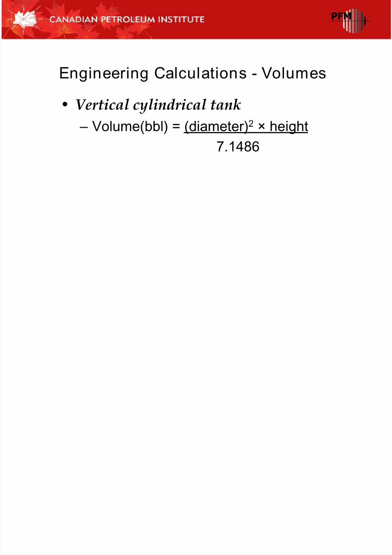
Engineering Calculations - Volumes
• Vertical cylindrical tank – Volume(bbl) = (diameter)2 × height
7.1486

8/10/2019 Part IX Engineering Calculations
http://slidepdf.com/reader/full/part-ix-engineering-calculations 5/51
PFM
Engineering Calculations - Volumes
• Horizontal cylindrical tank (half full orless)
Volume (bbl) =
(0.3168 d x h + 1.403 h2 - 0.933 x(h3/d)) × length
5.6146
• h is the height of the fluid level, ft
• d is the diameter of the tank, ft
• All diameters are expressed in inches; section
lengths are expressed in feet.

8/10/2019 Part IX Engineering Calculations
http://slidepdf.com/reader/full/part-ix-engineering-calculations 6/51
PFM
Engineering Calculations - Volumes
• Horizontal cylindrical tank (more thanhalf full)
Volume (bbl) = (diameter)2 × length -
7.1486
(0.3168 d x h + 1.403 h2 - 0.933 x(h3/d)) × length
5.6146
• h is the height of the fluid level, ft
• d is the diameter of the tank, ft
• All diameters are expressed in inches; section
lengths are expressed in feet.

8/10/2019 Part IX Engineering Calculations
http://slidepdf.com/reader/full/part-ix-engineering-calculations 7/51
PFM
Engineering Calculations - Volumes
• Drillpipe or drill collar capacity anddisplacement
– You can use calculations or look the data up in atable
Capacity (bbl/ft) = (inside diameter)2
1029.4
Displacement (bbl/ft) =
(outside diameter)2 - (inside diameter)2
1029.4

8/10/2019 Part IX Engineering Calculations
http://slidepdf.com/reader/full/part-ix-engineering-calculations 8/51
PFM
Engineering Calculations - Volumes
• Capacity of a long cylinder
bbl/100 ft = 0.0972 D2
bbl/inch = 0.000081 D2
bbl/1,000 ft = 0.972 D2
ft/bbl = 1029 ÷ D2
– Where D is the diameter of the cylinder, in

8/10/2019 Part IX Engineering Calculations
http://slidepdf.com/reader/full/part-ix-engineering-calculations 9/51
PFM
Engineering Calculations - Volumes
• Inside diameter of a steel cylinder
ID = OD2
- 0.3745W
• OD is the outside diameter, in
• W is the weight, lb/ft

8/10/2019 Part IX Engineering Calculations
http://slidepdf.com/reader/full/part-ix-engineering-calculations 10/51
PFM
Engineering Calculations - Volumes
• Pump Output – Normally found in tables
– Duplex Pump (bbl/stroke)
Output =
(2 x liner 2 - rod diameter 2) × stroke x Eff
6176.4
– Triplex Pump (bbl/stroke)
Output =
(liner inside diameter)
2
× 0.000243× stroke length

8/10/2019 Part IX Engineering Calculations
http://slidepdf.com/reader/full/part-ix-engineering-calculations 11/51
PFM
Engineering Calculations –
Annular Velocity
• Annular Velocity (commonly referred toas AV) is the average rate at which fluidis flowing in an annulus.
• A minimum annular mud velocity isneeded for proper hole cleaning.
• This minimum annular velocity dependson a number of factors, including rate of
penetration, cuttings size, hole angle,
mud density and rheology.
8/10/2019 Part IX Engineering Calculations
http://slidepdf.com/reader/full/part-ix-engineering-calculations 12/51
PFM
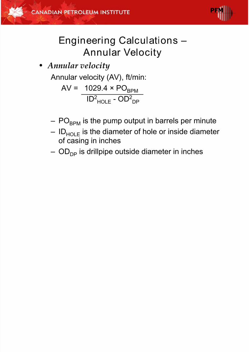
Engineering Calculations –
Annular Velocity
• Annular velocity Annular velocity (AV), ft/min:
AV = 1029.4 × POBPM
ID2HOLE - OD2DP
– POBPM is the pump output in barrels per minute
– IDHOLE is the diameter of hole or inside diameterof casing in inches
– ODDP is drillpipe outside diameter in inches

8/10/2019 Part IX Engineering Calculations
http://slidepdf.com/reader/full/part-ix-engineering-calculations 13/51
PFM
Engineering Calculations –
Circulation Time
• Total circulation time is the time (ornumber of strokes) required for mud tocirculate from the pump suction down the
drillstring, out the bit, back up theannulus to the surface, through the pitsand arrive at the pump suction onceagain.

8/10/2019 Part IX Engineering Calculations
http://slidepdf.com/reader/full/part-ix-engineering-calculations 14/51
PFM
Engineering Calculations –
Circulation Time
• Total circulation time
Total circulation time (min) =VSystem
VPump Output
– VSystem= Total system volume (active) (bbl)
– VPump Output = Pump output (bbl/min)

8/10/2019 Part IX Engineering Calculations
http://slidepdf.com/reader/full/part-ix-engineering-calculations 15/51
PFM
Engineering Calculations –
Circulation Time
• Bottoms-up time is the time (or numberof strokes) required for mud to circulate
from the bit at the bottom of the hole
back up the annulus to the surface.

8/10/2019 Part IX Engineering Calculations
http://slidepdf.com/reader/full/part-ix-engineering-calculations 16/51
PFM
Engineering Calculations –
Circulation Time
• Bottoms-up timeBottoms-up time (min) =
V Annulus
VPump Output
– V Annulus= Annular volume (bbl) – VPump Output= Pump output (bbl/min)

8/10/2019 Part IX Engineering Calculations
http://slidepdf.com/reader/full/part-ix-engineering-calculations 17/51
PFM
Engineering Calculations –
Hydrostatic Pressure
• Hydrostatic pressure (P HYD ) is the pressureexerted by the weight of a liquid on its“container” and is a function of the density of
the fluid and the True Vertical Depth (TVD) asshown by the equation below.
• In a well, this is the pressure exerted on the
casing and open hole sections of the wellboreand is the force that controls formation fluidsand prevents wellbore collapse.

8/10/2019 Part IX Engineering Calculations
http://slidepdf.com/reader/full/part-ix-engineering-calculations 18/51
PFM
Engineering Calculations –
Hydrostatic Pressure
• Formula for Hydrostatic pressure
PHYD (lb/in.2) = Mud weight (lb/gal) x TVD (ft) x 0.052
Conversion factor 0.052 =
12 in./ft
231 in.3/gal
PFM

8/10/2019 Part IX Engineering Calculations
http://slidepdf.com/reader/full/part-ix-engineering-calculations 19/51
PFM
Engineering Calculations –
Mass Volume Balance
• The ability to perform a material balanceis essential in drilling fluids engineering.
• Solids analysis, dilutions, increasingdensity and blending equations are allbased on material balances.
• To solve a mass balance, first determinethe known and unknown volumes anddensities and identify as component or
product.
PFM
8/10/2019 Part IX Engineering Calculations
http://slidepdf.com/reader/full/part-ix-engineering-calculations 20/51
PFM
Engineering Calculations –
Mass Volume Balance
• In general, the following steps lead to solving for the unknown:
– Step 1. Draw a diagram.
– Step 2. Determine components and products,mark volumes, and densities as known or
unknown.
– Step 3. Develop mass and volume balance.
– Step 4. Substitute one unknown into mass
balance and solve equation.
– Step 5. Determine second unknown and calculate
material consumption.
PFM

8/10/2019 Part IX Engineering Calculations
http://slidepdf.com/reader/full/part-ix-engineering-calculations 21/51
PFM
Engineering Calculations –
Mass Volume Balance
• Volume balanceVTotal = V1 + V2 + V3 + V4 + …
• Mass balanceVTotal r Total = V1r 1 + V2r 2 + V3r 3 + V4r 4 + …
V = Volume
r = Density
• These simple formula's as the basis of volume
and mass balance
PFM

8/10/2019 Part IX Engineering Calculations
http://slidepdf.com/reader/full/part-ix-engineering-calculations 22/51
PFM
Engineering Calculations –
Mass Volume Balance
• Example build a weighted mud – Determine the quantities of materials to
build 1,000 bbl (159 m3) of 16.0 lb/gal
(1.92 kg/l) mud with 20 lb/bbl (57 kg/m3)Bentonite use Barite as weighting
agent.
PFM

8/10/2019 Part IX Engineering Calculations
http://slidepdf.com/reader/full/part-ix-engineering-calculations 23/51
PFM
Engineering Calculations –
Mass Volume Balance
• Step 1. Draw a diagram.• Step 2. Determine densities and volumes with
known and unknown.
Components r (lb/gal) V (bbl)
Water 8.345 ?
Bentonite 21.7 22 (see below)Barite 35.0 ?
Mud 16.0 1,000
PFM

8/10/2019 Part IX Engineering Calculations
http://slidepdf.com/reader/full/part-ix-engineering-calculations 24/51
PFM
Engineering Calculations –
Mass Volume Balance
VGel = 20 lb/bbl x 1,000 bbl21.7 lb/gal x 42 gal/bbl
= 22 bbl• Step 3. Develop mass and volume
balance.
VMud r Mud = VWater r Water + VGel r Gel + VBar r Bar
VMud = VWater + VGel + VBar
PFM

8/10/2019 Part IX Engineering Calculations
http://slidepdf.com/reader/full/part-ix-engineering-calculations 25/51
PFM
Engineering Calculations –
Mass Volume Balance
• At this point the mass balance has twounknowns (VBar and VWater) that can bedetermined by using both equations. Solve the
volume balance for one unknown and thensubstitute it into the mass balance.
1,000 bbl = VWater + 22 bbl + VBar
VBar (bbl) = (1,000 – 22) – VWater
VBar (bbl) = 978 – VWater
PFM

8/10/2019 Part IX Engineering Calculations
http://slidepdf.com/reader/full/part-ix-engineering-calculations 26/51
PFM
Engineering Calculations –
Mass Volume Balance
• Step 4. Substitute one unknown into massbalance and solve equation.
V Mud r Mud = V Water r Water + V Gel r Gel + V Bar r Bar
1,000 x 16 = VWater x 8.345 + 22 x 21.7 + (978 – VWater) x 3516,000 = VWater x 8.345 + 477.4 + 34,230 – VWater x 35
VWater (35 – 8.345) = 477.4 + 34,230 – 16,000 = 18,707.4
VWater= 18,707.4
26.655
VWater= 702 bbl
PFM

8/10/2019 Part IX Engineering Calculations
http://slidepdf.com/reader/full/part-ix-engineering-calculations 27/51
PFM
Engineering Calculations –
Mass Volume Balance
• Step 5. Determine second unknown andcalculate material consumption. Thevolume of barite is derived from the
volume balance.VBar = (978 – VWater) = 978 – 702 = 276 bbl
lbBar = 276 bbl x (35 lb/gal x 42 gal/bbl)
= 276 bbl x 1,470 lb/bbl
= 405,720 lb
Or 4057 sacks (100lb).
PFM

8/10/2019 Part IX Engineering Calculations
http://slidepdf.com/reader/full/part-ix-engineering-calculations 28/51
PFM
Engineering Calculations – Solids Analysis
• The final use of material balance to bediscussed is determining solids analysis.
• Two cases are discussed, an unweighted freshwater system without oil and aweighted system containing salt and oil.
PFM

8/10/2019 Part IX Engineering Calculations
http://slidepdf.com/reader/full/part-ix-engineering-calculations 29/51
Engineering Calculations – Solids Analysis
• The material balance and volumeequation are as follows:
VMudr Mud = VWater r Water + VLGSr LGS
VMud = VWater + VLGS
VMud = Volume of mud
VWater = Volume of water VLGS = Volume of Low-Gravity Solids
r Mud= Density of mud or mud weight
r Water = Density of water
r LGS= Density of Low-Gravity Solids
PFM

8/10/2019 Part IX Engineering Calculations
http://slidepdf.com/reader/full/part-ix-engineering-calculations 30/51
Engineering Calculations – Solids Analysis
• The density of water, low-gravity solidsand mud are all known. If the volume ofmud is 100% and the mud weight is
known, the volume of the LGS can bedetermined.
• First, the volume of water must be solved for in the volume equation.
%VWater = 100% – %VLGS
PFM

8/10/2019 Part IX Engineering Calculations
http://slidepdf.com/reader/full/part-ix-engineering-calculations 31/51
Engineering Calculations – Solids Analysis
• Then this equation must be substitutedinto the material balance.
100% rMud = (100% – %VLGS) rWater + %VLGS rLGS
• Solving for the percent volume of low- gravity solids the following equation isobtained:%VLGS = 100% x (rMud – rWater)
(rLGS – rWater)
PFM

8/10/2019 Part IX Engineering Calculations
http://slidepdf.com/reader/full/part-ix-engineering-calculations 32/51
Engineering Calculations – Solids Analysis
• Example with un-weighted mud – An unweighted freshwater mud has a
density of 9.2 lb/gal. Determine the
percent of low-gravity solids in the system.%VLGS = 100% x (rMud – rWater)
(rLGS – rWater)
%VLGS = 100% x (9.2 – 8.345)
(21.7 – 8.345)
%VLGS = 6.4%
PFM

8/10/2019 Part IX Engineering Calculations
http://slidepdf.com/reader/full/part-ix-engineering-calculations 33/51
Engineering Calculations – Solids Analysis
• Example with weighted saltwater mud – The second case is a weighted system
containing sodium chloride and oil. This
material balance is one of the morecomplicated material balance evaluations
encountered in drilling fluids engineering.
PFM

8/10/2019 Part IX Engineering Calculations
http://slidepdf.com/reader/full/part-ix-engineering-calculations 34/51
Engineering Calculations – Solids Analysis
• For this example, the following is given:
– Mud weight 16.0 lb/gal
– Chlorides 50,000 mg/l
– Oil (%) 5 (7.0 lb/gal)
– Retort water (%) 63 – Weight material Barite (35.0 lb/gal)
PFM

8/10/2019 Part IX Engineering Calculations
http://slidepdf.com/reader/full/part-ix-engineering-calculations 35/51
Engineering Calculations – Solids Analysis
• Step 1. Draw a component diagram.• Step 2. Determine the known and unknown
variables and label the components. Use theappropriate density for the HGS, LGS and oil.
Components r (lb/gal) V (%)
HGS 35.0 ?
LGS 21.7 ?
Oil 7.0 5%Salt ? ?
Water 8.345 63%
Mud 16.0 100%
PFM

8/10/2019 Part IX Engineering Calculations
http://slidepdf.com/reader/full/part-ix-engineering-calculations 36/51
Engineering Calculations – Solids Analysis
• Step 3. Write the material balance andvolume equations.
VMud rMud = VHGS rHGS + VLGS rLGS + VSW rSW
+ VOil rOil
VMud = VHGS + VLGS + VSW + VOil = 100%
PFM

8/10/2019 Part IX Engineering Calculations
http://slidepdf.com/reader/full/part-ix-engineering-calculations 37/51
Engineering Calculations – Solids Analysis
• The volume of saltwater cannot be determineddirectly. The retort measures the quantity ofdistilled water in the mud sample (VWater). The
volume of salt (VSalt) can be calculated aftermeasuring the chloride concentration of thefiltrate (saltwater).
• The volume of saltwater is equal to the retortwater volume plus the calculated salt volume:
VSW = VWater + VSalt
PFM

8/10/2019 Part IX Engineering Calculations
http://slidepdf.com/reader/full/part-ix-engineering-calculations 38/51
Engineering Calculations – Solids Analysis
• The equations are changed to use thesevariables.
VMud rMud = VHGS rHGS + VLGS rLGS + (Vwater +
VSalt) rSW + VOil rOil
VMud = VHGS + VLGS + (Vwater + VSalt) + VOil =
100%
PFM

8/10/2019 Part IX Engineering Calculations
http://slidepdf.com/reader/full/part-ix-engineering-calculations 39/51
Engineering Calculations – Solids Analysis
• Step 4. Develop the correspondingequations to solve for the unknowns.
– The density of the saltwater (r SW) can be
calculated from the chloride concentration.The following equation is a curve fit of
density-to-chloride concentration for
sodium chloride.SGSW = 1+1.166 x 10⁻⁶ x (mg/l Cl– ) – 8.375 x 10⁻¹³ x (mg/l Cl– ) 2
+1.338 x 10⁻¹⁸ x (mg/l Cl– )3
PFM

8/10/2019 Part IX Engineering Calculations
http://slidepdf.com/reader/full/part-ix-engineering-calculations 40/51
Engineering Calculations – Solids Analysis
SGSW = 1+1.166 x 10–6
x (50000) – 8.375 x 10–13
x (50000)2
+1.338x 10–18 x (50000)3= 1.0564
rSW (lb/gal) = 1.0564 x 8.345 = 8.82 lb/gal
• The weight percent sodium chloride of thesaltwater is calculated by the followingexpression:
% NaCl (wt) = mg/l Cl– x 1.65
SGSW x 10,000
PFM

8/10/2019 Part IX Engineering Calculations
http://slidepdf.com/reader/full/part-ix-engineering-calculations 41/51
Engineering Calculations – Solids Analysis
• Substitute% NaCl (wt) = 50000 x 1.65
1.0564 x 10,000
= 7.81%
PFM

8/10/2019 Part IX Engineering Calculations
http://slidepdf.com/reader/full/part-ix-engineering-calculations 42/51
Engineering Calculations – Solids Analysis
• The volume percent salt of the mud (VSalt)can be calculated from the specific gravityand weight percent sodium chloride of
the saltwater by the following equation:VSalt = VWater 100 -1
SGSW (100 – % NaCl (wt))
VSalt =63% 100 -11.0564 (100 – 7.81))
VSalt = 1.69%
PFM

8/10/2019 Part IX Engineering Calculations
http://slidepdf.com/reader/full/part-ix-engineering-calculations 43/51
Engineering Calculations – Solids Analysis
• Frequently this salt concentration isreported in pounds per barrel using thefollowing conversion:
NaCl (lb/bbl)= (VWater + VSalt) x mg/l Cl– x 1.65 x 3.5
10,000 100
NaCl (lb/bbl) = (63 + 1.69) x 50000 x 1.65 x 3.510000 100
= 18.68 lb/bbl
PFM

8/10/2019 Part IX Engineering Calculations
http://slidepdf.com/reader/full/part-ix-engineering-calculations 44/51
Engineering Calculations – Solids Analysis
• Step 5. Use the material balance andvolume equations to solve for theremaining unknowns.
• VHGS and VLGS are the only remainingunknowns. First the volume equation issolved for VLGS in terms of VHGS and
substituted into the material balanceequation to obtain:VMud rMud = VHGS rHGS + VLGS rLGS + (VWater + VSalt) rSW
+ VOil rOil
PFM

8/10/2019 Part IX Engineering Calculations
http://slidepdf.com/reader/full/part-ix-engineering-calculations 45/51
Engineering Calculations – Solids Analysis
VHGS rHGS = VMud rMud – (100 – VWater – VSalt – VOil – VHGS) rLGS – (VWater +VSalt)rSW – VOil rOil
VHGS = 100 rMud – (100 – VWater – VSalt – VOil) rLGS – (VWater + VSalt)rSW – VOil rOil
rHGS – rLGS
VHGS =16 x 100 – (100 – 63 – 1.69 – 5) x 21.7 – (1.69 + 63) x 8.8 – 7 x 5
(35 – 21.7)
VHGS
= 25.41%
PFM

8/10/2019 Part IX Engineering Calculations
http://slidepdf.com/reader/full/part-ix-engineering-calculations 46/51
Engineering Calculations – Solids Analysis
• This concentration is converted to lb/bbl unitsas follows:
HGS (lb/bbl) = VHGS x rHGS
100
HGS (lb/bbl) = 25.41% x (35 lb/gal x 42 gal/bbl)100
HGS (lb/bbl) = 373.5 lb/bbl
PFM

8/10/2019 Part IX Engineering Calculations
http://slidepdf.com/reader/full/part-ix-engineering-calculations 47/51
Engineering Calculations – Solids Analysis
Next, VLGS can be determined using thevolume equation:
VLGS = 100% – VWater – VSalt – VOil – VHGS
VLGS = 100% – 63% – 1.69% – 5% – 25.41%= 4.9%
PFM

8/10/2019 Part IX Engineering Calculations
http://slidepdf.com/reader/full/part-ix-engineering-calculations 48/51
Engineering Calculations – Solids Analysis
• This concentration is converted to lb/bbl unitsas follows:
LGS (lb/bbl) = VLGS x rLGS
100
LGS (lb/bbl) = 4.9% x (21.7 lb/gal x 42 (gal/bbl))
100LGS (lb/bbl) = 44.7 lb/bbl
PFM

8/10/2019 Part IX Engineering Calculations
http://slidepdf.com/reader/full/part-ix-engineering-calculations 49/51
Engineering Calculations – Solids Analysis
Volume (%)V H20 63
V OIL
5
V SALT 1.69
V HGS 25.41
V LGS 4.9Total 100.0
PFM

8/10/2019 Part IX Engineering Calculations
http://slidepdf.com/reader/full/part-ix-engineering-calculations 50/51
Engineering Calculations – Solids Analysis Weight (lb/bbl)
H2O [0.63 x 350] 220.5Oil [0.05 x 7 x 42] 14.7
NaCl 18.7
HGS 373.5
LGS 44.7 .
Total 672.1
rMud (lb/gal) = 672.1 = 16.0 lb/gal
42
PFM

8/10/2019 Part IX Engineering Calculations
http://slidepdf.com/reader/full/part-ix-engineering-calculations 51/51
Engineering Calculations – Solids Analysis
• End