part no. nvcuq072a-d4 - nichia · 2019-12-03 · nvcuq072a-d4 ( " ) unit: mm, ¶ j tolerance:...
TRANSCRIPT
NICHIA STS-DA1-5432E <Cat.No.191127>
NICHIA CORPORATION
SPECIFICATIONS FOR UV LED
PART NO. NVCUQ072A-D4 ● Built-in ESD Protection Device ● RoHS Compliant

NICHIA STS-DA1-5432E <Cat.No.191127>
1
SPECIFICATIONS
(1) Absolute Maximum Ratings
Item Symbol Absolute Maximum Rating Unit
Forward Current IF 6.6 A
Allowable Reverse Current IR 85 mA
Power Dissipation PD 320 W
Operating Temperature Topr 0~85 °C
Storage Temperature Tstg -40~100 °C
Junction Temperature TJ 130 °C
* Absolute Maximum Ratings at TTH=25°C.
* The operating Temperature range is the range of Thermistor temperatures (TTH).
* Do not operate the LEDs in environments where temperature and humidity fluctuate greatly (i.e. causing condensation to form).
(2) Initial Electrical/Optical Characteristics
Item Symbol Condition Typ Max Unit
U365
Forward Voltage VF IF=6A 46.3 - V
Radiant Flux Φe IF=6A 92 - W
Peak Wavelength λp IF=6A 365 - nm
U385
Forward Voltage VF IF=6A 44.8 - V
Radiant Flux Φe IF=6A 112 - W
Peak Wavelength λp IF=6A 385 - nm
U395
Forward Voltage VF IF=6A 44.1 - V
Radiant Flux Φe IF=6A 108 - W
Peak Wavelength λp IF=6A 395 - nm
Spectrum Half Width Δλ IF=6A 12 - nm
Thermal Resistance RθJC - 0.030 0.038 °C/W
* Characteristics at TTH=25°C.
* Radiant Flux value as per CIE 127:2007 standard.
* RθJC is the thermal resistance from the junction to the TC measurement point. (Heat sink used: Copper, t=3mm, Thermal grease
used: 4.3W/m・K, t=0.1mm)
* It is recommended to operate the LEDs at a current greater than 10% of the sorting current to stabilize the LED characteristics.

NICHIA STS-DA1-5432E <Cat.No.191127>
2
RANKS
Item Rank Min Max Unit
Forward Voltage
B480 48.0 48.5
V
B475 47.5 48.0
B470 47.0 47.5
B465 46.5 47.0
B460 46.0 46.5
B455 45.5 46.0
B450 45.0 45.5
B445 44.5 45.0
B440 44.0 44.5
B435 43.5 44.0
B430 43.0 43.5
B425 42.5 43.0
Radiant Flux
Pw120 120.0 132.0
W
Pw109a 109.1 120.0
Pw099b 99.2 109.1
Pw090b 90.2 99.2
Pw082 82.0 90.2
Pw074f 74.5 82.0
Peak Wavelength
U395 390 400
nm U385 380 390
U365 360 370
* Ranking at TTH=25°C.
* Forward Voltage Tolerance: ±0.35V
* Radiant Flux Tolerance: ±6%
* Peak Wavelength Tolerance: ±3nm
* LEDs from the above ranks will be shipped. The rank combination ratio per shipment will be decided by Nichia.
Forward Voltage Ranks by Peak Wavelength
Ranking by
Forward Voltage
Ranking by
Peak Wavelength
B425 B430 B435 B440 B445 B450 B455 B460 B465 B470 B475 B480
U365
U385
U395
Radiant Flux Ranks by Peak Wavelength
Ranking by
Radiant Flux
Ranking by
Peak Wavelength
Pw074f Pw082 Pw090b Pw099b Pw109a Pw120
U365
U385,U395

NICHIA STS-DA1-5432E <Cat.No.191127>
3
OUTLINE DIMENSIONS
管理番号 No.
(単位 Unit: mm)
This product complies with RoHS Directive.
本製品はRoHS指令に適合しております。*
The dimension(s) in parentheses are for reference purposes.
括弧で囲まれた寸法は参考値です。*
STS-DA7-14613
NVCUQ072A-D4
(単位 Unit: mm, 公差 Tolerance: ±0.2)
This product is non-soldering-compliant.Do not solder this product.
本製品ははんだ付けに非対応です。はんだ付けでの使用をしないで下さい。*
When attaching the LEDs to the heat sink, etc., Nichia recommends using a thermal interface material that has a low thermal resistance (i.e. thermal grease).
製品と筐体間の接続には放熱グリスなど低熱抵抗の放熱材料を用いることを推奨します。
*
項目 Item
基板材質Substrate Materials
カバー材質Cover Materials
内容 Description
窒化アルミニウムAluminum Nitride
硬質ガラス
Hard Glass
コネクタConnector
Hirose ElectricDF65-4P-1.7V(21)DF65-6P-1.7V(21)
質量Weight 5.6g(TYP)
Connector 1
AK
2
Connector 2
NTCサーミスタNTC Thermistor
1
1 3
42
保護素子Protection Device
3 5
64
保護素子Protection Device
(3.1)
(2.8)
1.3
7.2
523.5
Cover
Substrate
1 2 3 4 1 2 3 4 5 6
17
24.9
4 3.5
31
Φ3.2
45
Connector 2Connector 1
3-Φ3.6

NICHIA STS-DA1-5432E <Cat.No.191127>
4
TRAY DIMENSIONS
数量は1トレイにつき 6個入りです。*
(単位 Unit: mm)
Tray Size: 6pcs STS-DA7-14614
Nxxxx072x
管理番号 No.
All dimensions shown are for reference only and are not guaranteed.
寸法は参考です。*
120
118
(25)
68
(13)
6.8
51
118
120
45.4
25.3

NICHIA STS-DA1-5432E <Cat.No.191127>
5
PACKAGING - TRAY PACK
Nichia LED
アルミ防湿袋を入れます。
Moisture-proof bags are packedin cardboard boxes.
PS箱PS box
Nichia LED
PS箱を並べて入れ、ダンボールで仕切ります。
PS boxes are packed in cardboardboxes with corrugated partitions.
PHM箱PHM box
STS-DA7-12138C
Part No. Nxxxxxxx
Label ラベル
Label ラベル
No.
RoHS
Nxxxxxxx
UV LED
*******
RRRPCS
RANK:QTY.:
NICHIA CORPORATION491 OKA, KAMINAKA, ANAN, TOKUSHIMA, JAPAN
PART NO.:
RoHS
Nxxxxxxx
UV LED
*******
NICHIA CORPORATION 491 OKA, KAMINAKA, ANAN, TOKUSHIMA, JAPAN
LOT:QTY.:
YMxxxx-RRRPCS
PART NO.:
If not provided, it will not be indicated on the label.******* is the customer part number.
客先型名が設定されていない場合は空白です。
*
客先型名を*******で示します。
参照して下さい。
For details, see "LOT NUMBERING CODE"in this document.
*
ロット表記方法についてはロット番号の項を
Desiccantsシリカゲル
Trayトレイ
Seal熱シール
Moisture-proof bagアルミ防湿袋
シリカゲルとともにトレイをアルミ防湿袋に入れ、熱シールにより封をします。Trays are shipped with desiccants in heat-sealed moisture-proof bags.
Do not drop or expose the box to external forces as it may damage the products.
取り扱いに際して、落下させたり、強い衝撃を与えたりしますと、製品を損傷させる原因になりますので注意して下さい。
Do not expose to water. The box is not water-resistant.ダンボールには防水加工がされておりませんので、梱包箱が水に濡れないよう注意して下さい。
Using the original package material or equivalent in transit is recommended.
*
*
*
*
輸送、運搬に際して弊社よりの梱包状態あるいは同等の梱包を行って下さい。
Products shipped on trays are packed in a moisture-proof bag.They are shipped in cardboard boxes to protect them from external forces during transportation.
本製品はトレイに入れたのち、輸送の衝撃から保護するためダンボールで梱包します。
Warning and Explanatory Labels 警告ラベル
UV LED・ 「UV LEDは紫外領域の光(UV光)を発します。」・ 「UV光は人間の目には見えませんが、 光が見えていなくてもUV光により目を傷める可能性があります。」・ 「UV光を直接目にあてないでください。必ず適切な防具を着用してください。」・ 「UV LEDを組み込んだ製品には、適切な警告表示をしてください。」
・ UV LEDs emit light in the ultraviolet region (UV light).・ UV light is invisible and may be harmful to the human eye.・ Do not expose the eyes directly to the UV light. Wear appropriate protective gear when handling.・ Use appropriate warning signs/labels on devices using the UV LEDs.

NICHIA STS-DA1-5432E <Cat.No.191127>
6
LOT NUMBERING CODE
Lot Number is presented by using the following alphanumeric code.
YMxxxx - RRR
Y - Year
Year Y
2018 I
2019 J
2020 K
2021 L
2022 M
2023 N
M - Month
Month M Month M
1 1 7 7
2 2 8 8
3 3 9 9
4 4 10 A
5 5 11 B
6 6 12 C
xxxx-Nichia's Product Number
RRR-Ranking by Wavelength, Ranking by Radiant Flux, Ranking by Forward Voltage

NICHIA STS-DA1-5432E <Cat.No.191127>
7
DERATING CHARACTERISTICS
NVCUQ072A-D4
管理番号 No. STS-DA7-14615A
0
5
10
0 20 40 60 80 100 120
Derating1
(85, 6.60)(78, 6.60)(47, 6.60)
(85, 5.20)
(85, 2.60)
サーミスタ温度-許容順電流特性
Thermistor Temperature vs
Allowable Forward Current
許容順電流
Allow
able
Forw
ard
Curr
ent(
A)
サーミスタ温度
Thermistor Temperature(°C)
0.079°C/W
0.1°C/W
0.2°C/W
θJTHR =
θJTHR =
θJTHR =
* RθJTHの算出は注意事項熱の発生を参照して下さい。For calculation of RθJTH, see the "Thermal Management" of this specification.

NICHIA STS-DA1-5432E <Cat.No.191127>
8
OPTICAL CHARACTERISTICS
NVCUQ072A-D4
管理番号 No. STS-DA7-14616
0.0
0.2
0.4
0.6
0.8
1.0
300 350 400 450 500 550 600
Spectrum
相対放射強度
Relative Radiant Intensity(a.u.)
90°
80°
70°
60°
50°
40°
30°
20°
10°0°
-10°-20°
-30°
-40°
-50°
-60°
-70°
-80°
-90°
Directivity1
発光スペクトル
Spectrum
相対発光強度
Rela
tive E
mis
sio
n I
nte
nsity(a
.u.)
波長
Wavelength(nm)
指向特性
Directivity
放射角度
Radia
tion A
ngle
1 0.5 0 0.5 1
6AIFP=T
A=25°C
6AIFP=T
A=25°C
* 本特性はピーク波長ランクU365xに対応しています。
The graphs above show the characteristics for U365x LEDs of this product.
* 本特性は参考です。All characteristics shown are for reference only and are not guaranteed.

NICHIA STS-DA1-5432E <Cat.No.191127>
9
OPTICAL CHARACTERISTICS
NVCUQ072A-D4
管理番号 No. STS-DA7-14617
0.0
0.2
0.4
0.6
0.8
1.0
300 350 400 450 500 550 600
Spectrum
相対放射強度
Relative Radiant Intensity(a.u.)
90°
80°
70°
60°
50°
40°
30°
20°
10°0°
-10°-20°
-30°
-40°
-50°
-60°
-70°
-80°
-90°
Directivity1
発光スペクトル
Spectrum
相対発光強度
Rela
tive E
mis
sio
n I
nte
nsity(a
.u.)
波長
Wavelength(nm)
指向特性
Directivity
放射角度
Radia
tion A
ngle
1 0.5 0 0.5 1
6AIFP=T
A=25°C
6AIFP=T
A=25°C
* 本特性はピーク波長ランクU385xに対応しています。
The graphs above show the characteristics for U385x LEDs of this product.
* 本特性は参考です。All characteristics shown are for reference only and are not guaranteed.

NICHIA STS-DA1-5432E <Cat.No.191127>
10
OPTICAL CHARACTERISTICS
NVCUQ072A-D4
管理番号 No. STS-DA7-14618
0.0
0.2
0.4
0.6
0.8
1.0
300 350 400 450 500 550 600
Spectrum
相対放射強度
Relative Radiant Intensity(a.u.)
90°
80°
70°
60°
50°
40°
30°
20°
10°0°
-10°-20°
-30°
-40°
-50°
-60°
-70°
-80°
-90°
Directivity1
発光スペクトル
Spectrum
相対発光強度
Rela
tive E
mis
sio
n I
nte
nsity(a
.u.)
波長
Wavelength(nm)
指向特性
Directivity
放射角度
Radia
tion A
ngle
1 0.5 0 0.5 1
6AIFP=T
A=25°C
6AIFP=T
A=25°C
* 本特性はピーク波長ランクU395xに対応しています。
The graphs above show the characteristics for U395x LEDs of this product.
* 本特性は参考です。All characteristics shown are for reference only and are not guaranteed.

NICHIA STS-DA1-5432E <Cat.No.191127>
11
FORWARD CURRENT CHARACTERISTICS / TEMPERATURE CHARACTERISTICS
NVCUQ072A-D4
管理番号 No. STS-DA7-14619
35
40
45
50
-60 -40 -20 0 20 40 60 80 100 120
TaVf
0.4
0.6
0.8
1.0
1.2
1.4
-60 -40 -20 0 20 40 60 80 100 120
TaIv
1
10
35 40 45 50
VfIf
66.6
相対放射束
Rela
tive R
adia
nt
Flu
x(a
.u.)
周囲温度-相対放射束特性
Ambient Temperature vs
Relative Radiant Flux
順電流
Forw
ard
Curr
ent(
A)
0.0
0.5
1.0
1.5
2.0
0 2 4 6 8 10
IfIv
相対放射束
Rela
tive R
adia
nt
Flu
x(a
.u.)
順電流-相対放射束特性
Forward Current vs
Relative Radiant Flux
順電流
Forward Current(A)
順電圧-順電流特性
Forward Voltage vs
Forward Current
周囲温度-順電圧特性
Ambient Temperature vs
Forward Voltage
順電圧
Forward Voltage(V)
順電圧
Forw
ard
Voltage(V
)
周囲温度
Ambient Temperature(°C)
周囲温度
Ambient Temperature(°C)
* 本特性は参考です。All characteristics shown are for reference only and are not guaranteed.
=25°CTA
IFP=6A
IFP=6A
* 本特性はピーク波長ランクU365xに対応しています。
The graphs above show the characteristics for U365x LEDs of this product.
TA
=25°C

NICHIA STS-DA1-5432E <Cat.No.191127>
12
FORWARD CURRENT CHARACTERISTICS / TEMPERATURE CHARACTERISTICS
NVCUQ072A-D4
管理番号 No. STS-DA7-14620
35
40
45
50
-60 -40 -20 0 20 40 60 80 100 120
TaVf
0.6
0.8
1.0
1.2
1.4
-60 -40 -20 0 20 40 60 80 100 120
TaIv
1
10
35 40 45 50
VfIf
66.6
相対放射束
Rela
tive R
adia
nt
Flu
x(a
.u.)
周囲温度-相対放射束特性
Ambient Temperature vs
Relative Radiant Flux
順電流
Forw
ard
Curr
ent(
A)
0.0
0.5
1.0
1.5
2.0
0 2 4 6 8 10
IfIv
相対放射束
Rela
tive R
adia
nt
Flu
x(a
.u.)
順電流-相対放射束特性
Forward Current vs
Relative Radiant Flux
順電流
Forward Current(A)
順電圧-順電流特性
Forward Voltage vs
Forward Current
周囲温度-順電圧特性
Ambient Temperature vs
Forward Voltage
順電圧
Forward Voltage(V)
順電圧
Forw
ard
Voltage(V
)
周囲温度
Ambient Temperature(°C)
周囲温度
Ambient Temperature(°C)
* 本特性は参考です。All characteristics shown are for reference only and are not guaranteed.
=25°CTA
IFP=6A
IFP=6A
* 本特性はピーク波長ランクU385xに対応しています。
The graphs above show the characteristics for U385x LEDs of this product.
TA
=25°C

NICHIA STS-DA1-5432E <Cat.No.191127>
13
FORWARD CURRENT CHARACTERISTICS / TEMPERATURE CHARACTERISTICS
NVCUQ072A-D4
管理番号 No. STS-DA7-14621
35
40
45
50
-60 -40 -20 0 20 40 60 80 100 120
TaVf
0.6
0.8
1.0
1.2
1.4
-60 -40 -20 0 20 40 60 80 100 120
TaIv
1
10
35 40 45 50
VfIf
66.6
相対放射束
Rela
tive R
adia
nt
Flu
x(a
.u.)
周囲温度-相対放射束特性
Ambient Temperature vs
Relative Radiant Flux
順電流
Forw
ard
Curr
ent(
A)
0.0
0.5
1.0
1.5
2.0
0 2 4 6 8 10
IfIv
相対放射束
Rela
tive R
adia
nt
Flu
x(a
.u.)
順電流-相対放射束特性
Forward Current vs
Relative Radiant Flux
順電流
Forward Current(A)
順電圧-順電流特性
Forward Voltage vs
Forward Current
周囲温度-順電圧特性
Ambient Temperature vs
Forward Voltage
順電圧
Forward Voltage(V)
順電圧
Forw
ard
Voltage(V
)
周囲温度
Ambient Temperature(°C)
周囲温度
Ambient Temperature(°C)
* 本特性は参考です。All characteristics shown are for reference only and are not guaranteed.
=25°CTA
IFP=6A
IFP=6A
* 本特性はピーク波長ランクU395xに対応しています。
The graphs above show the characteristics for U395x LEDs of this product.
TA
=25°C

NICHIA STS-DA1-5432E <Cat.No.191127>
14
FORWARD CURRENT CHARACTERISTICS / TEMPERATURE CHARACTERISTICS
NVCUQ072A-D4
管理番号 No. STS-DA7-14622
359
361
363
365
367
369
371
1 10
IfλD
359
361
363
365
367
369
371
-60 -40 -20 0 20 40 60 80 100 120
TaλD 6AIFP=
順電流-ピーク波長特性Forward Current vs
Peak Wavelength
順電流
Forward Current(A)
周囲温度-ピーク波長特性
Ambient Temperature vs
Peak Wavelength
Peak W
avele
ngth
(nm
)
ピーク波長
Peak W
avele
ngth
(nm
)
ピーク波長
周囲温度
Ambient Temperature(°C)
* 本特性は参考です。All characteristics shown are for reference only and are not guaranteed.
TA=25°C
* 本特性はピーク波長ランクU365xに対応しています。
The graphs above show the characteristics for U365x LEDs of this product.

NICHIA STS-DA1-5432E <Cat.No.191127>
15
FORWARD CURRENT CHARACTERISTICS / TEMPERATURE CHARACTERISTICS
NVCUQ072A-D4
管理番号 No. STS-DA7-14623
379
381
383
385
387
389
391
1 10
IfλD
379
381
383
385
387
389
391
-60 -40 -20 0 20 40 60 80 100 120
TaλD 6AIFP=
順電流-ピーク波長特性Forward Current vs
Peak Wavelength
順電流
Forward Current(A)
周囲温度-ピーク波長特性
Ambient Temperature vs
Peak Wavelength
Peak W
avele
ngth
(nm
)
ピーク波長
Peak W
avele
ngth
(nm
)
ピーク波長
周囲温度
Ambient Temperature(°C)
* 本特性は参考です。All characteristics shown are for reference only and are not guaranteed.
TA=25°C
* 本特性はピーク波長ランクU385xに対応しています。
The graphs above show the characteristics for U385x LEDs of this product.
NICHIA STS-DA1-5432E <Cat.No.191127>
16
FORWARD CURRENT CHARACTERISTICS / TEMPERATURE CHARACTERISTICS
NVCUQ072A-D4
管理番号 No. STS-DA7-14624
389
391
393
395
397
399
401
1 10
IfλD
389
391
393
395
397
399
401
-60 -40 -20 0 20 40 60 80 100 120
TaλD 6AIFP=
順電流-ピーク波長特性Forward Current vs
Peak Wavelength
順電流
Forward Current(A)
周囲温度-ピーク波長特性
Ambient Temperature vs
Peak Wavelength
Peak W
avele
ngth
(nm
)
ピーク波長
Peak W
avele
ngth
(nm
)
ピーク波長
周囲温度
Ambient Temperature(°C)
* 本特性は参考です。All characteristics shown are for reference only and are not guaranteed.
TA=25°C
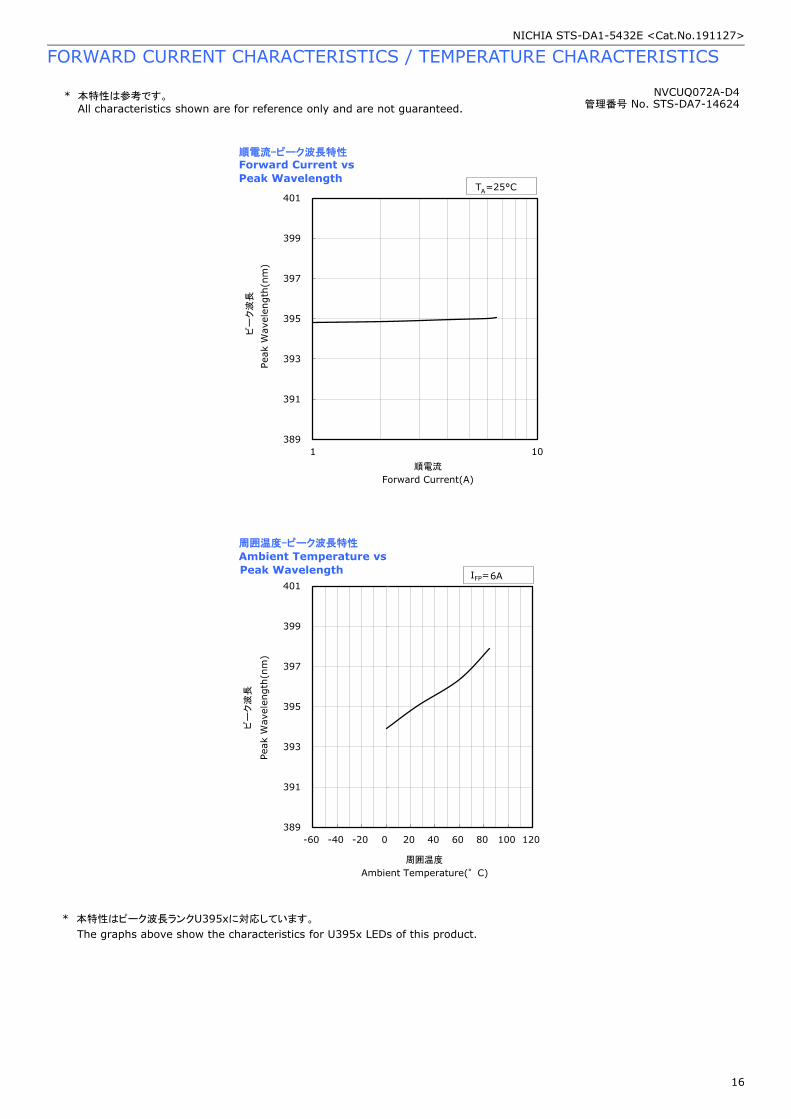
* 本特性はピーク波長ランクU395xに対応しています。
The graphs above show the characteristics for U395x LEDs of this product.

NICHIA STS-DA1-5432E <Cat.No.191127>
17
RELIABILITY
(1) Tests and Results
Test Reference
Standard Test Conditions
Test
Duration
Failure
Criteria
#
Units
Failed/Tested
Thermal Shock(Air to Air) -40°C to 100°C, 15min dwell 100cycles #1 0/2
High Temperature
Storage
JEITA ED-4701
200 201 TA=100°C 1000hours #1 0/2
Low Temperature
Storage
JEITA ED-4701
200 202 TA=-40°C 1000hours #1 0/2
Room Temperature
Operating Life TA=25°C, TW=30°C, IF=6.6A 1000hours #1 0/2
Vibration JEITA ED-4701
400 403
200m/s2, 100~2000~100Hz,
4cycles, 4min, each X, Y, Z 48minutes #1 0/2
Electrostatic Discharges JEITA ED-4701
300 304
HBM, 2kV, 1.5kΩ, 100pF, 3pulses,
alternately positive or negative #1 0/2
NOTES:
1) RθJTH≈0.106°C/W
2) TW= Cooling Water Temperature: °C
3) Measurements are performed after allowing the LEDs to return to room temperature.
(2) Failure Criteria
Criteria # Items Conditions Failure Criteria
#1 Forward Voltage(VF) IF=6A >Initial value×1.1
Radiant Flux(ΦE) IF=6A <Initial value×0.7

NICHIA STS-DA1-5432E <Cat.No.191127>
18
CAUTIONS
(1) Storage
Conditions Temperature Humidity Time
Storage Before Opening Aluminum Bag ≤30°C ≤90%RH Within 1 Year from Delivery Date
After Opening Aluminum Bag ≤30°C ≤70%RH ≤168hours
● After opening the moisture-proof aluminum bag, the LEDs should be installed into an end product immediately. If a PCB is used
to mount the LEDs before installing into an end product, these processes must be completed within the range of the conditions
stated above. Unused remaining LEDs should be stored with silica gel desiccants in a hermetically sealed container, preferably the
original moisture-proof bags for storage and resealing this bag.
● This LED has gold-plated parts; if the LEDs are exposed to a corrosive environment, it may cause the plated surface to tarnish
causing issues. Ensure that when storing LEDs, a hermetically sealed container is used. Nichia recommends placing them back to
the original moisture-proof bag and reseal it.
● To prevent substances/gases from affecting the plated surface, ensure that the parts/materials used with the LEDs in the same
assembly/system do not contain sulfur (e.g. gasket/seal, adhesive, etc.). If the plating is contaminated, it may cause issues (e.g.
electric connection failures). If a gasket/seal is used, silicone rubber gaskets/seals are recommended; ensure that this use of
silicone does not result in issues (e.g. electrical connection failures) caused by low molecular weight volatile siloxane.
● To avoid condensation, the LEDs must not be stored in areas where temperature and humidity fluctuate greatly.
● Do not store the LEDs in a dusty environment.
● Do not expose the LEDs to direct sunlight and/or an environment over a long period of time where the temperature is higher than
normal room temperature.
(2) Directions for Use
● Nichia recommends designing the circuit to ensure that each LED is driven by a separate power supply.
● If two or more LEDs are connected in parallel, the current will be split between them (i.e. current division); this may cause the
currents flowing through the LEDs to vary due to the variation in the forward voltage characteristics of the LEDs on the circuit, and
in some cases, excessive current (i.e. exceeding the Absolute Maximum Rating). The circuit must be designed to ensure that the
Absolute Maximum Ratings are not exceeded for each LED. The LEDs should be operated at a constant current per LED. In the
case of operating at a constant voltage, Circuit B is recommended. If Circuit A is used, it may cause issues (i.e. a variation in the
current flowing through the LEDs).
(A)
...
(B)
...
● This LED is designed to be operated at a forward current. Ensure that no voltage is applied to the LED in the forward/reverse
direction while the LED is off. If the LEDs are used in an environment where reverse voltages are applied to the LED continuously,
it may cause electrochemical migration to occur causing the LED to be damaged. When not in use for a long period of time, the
system’s power should be turned off to ensure that there are no issues/damage.
● To stabilize the LED characteristics while in use, Nichia recommends that the LEDs are operated at currents ≥ 10% of the sorting
current.
● Ensure that transient excessive voltages (e.g. lightning surge) are not applied to the LEDs.
● If the LEDs are used for outdoor applications, ensure that necessary measures are taken (e.g. protecting the LEDs from water/salt
damage and high humidity).
● Although this LED is specifically designed to emit invisible light, a small amount of light in the visible region exists in the emission
spectrum. Ensure that when using the LEDs for sensors, verification is performed to ensure that the emission spectrum is fit for
the intended use.
● If this product is stored and/or used constantly under high humidity conditions, it may accelerate the deterioration of the die; this
may cause the radiant flux to decrease. If the LEDs are stored and/or used under these conditions, sufficient verification must be
done prior to use to ensure there are no issues for the chosen application.
● Do not design this LED into applications where condensation may occur. If the LEDs are stored/operated in these environments,
it may cause issues (e.g. current leaks that cause the radiant flux to decrease).

NICHIA STS-DA1-5432E <Cat.No.191127>
19
(3) Handling Precautions
● Do not handle the LEDs with bare hands as it will contaminate the LED surface and may affect the optical characteristics: it might
cause the LED to be deformed and/or the wire to break, which will cause the LED not to illuminate. The lead could also cause an
injury.
● Ensure that when handling the LEDs with tweezers, excessive force is not applied to the LED. Otherwise, it may cause damage to
the lens and/or the substrate (e.g. cut, scratch, chip, crack, delamination, and deformation) and the wire to break causing a
catastrophic failure (i.e. the LED not to illuminate).
● Dropping may cause damage to the LED (e.g. deformation).
● Do not stack the LEDs on top of one another, regardless of whether the LEDs are attached to heat sinks or not. Otherwise, it may
cause damage to the lens and the substrate (e.g. cut, scratch, chip, crack, delamination, and deformation) and the wire to break
causing a catastrophic failure (i.e. the LED not to illuminate).
(4) Design Consideration
● Volatile organic compounds that have been released from materials present around the LEDs (e.g. housing, gasket/seal, adhesive,
secondary lens, lens cover, thermal grease, etc.) may adhere to the LED glass cover and other areas (e.g. package). If the LEDs
are being used in a hermetically sealed environment, these volatile compounds can discolor after being exposed to heat and/or
photon energy and it may greatly reduce the LED light output. In this case, ventilating the environment may improve the
reduction in light output. Perform a light-up test of the chosen application for optical evaluation to ensure that there are no issues.
● When attaching the LEDs to the heat sink, etc., Nichia recommends using a thermal interface material that has a low thermal
resistance (i.e. thermal grease).
(5) Electrostatic Discharge (ESD)
● This LED is sensitive to transient excessive voltages (e.g. ESD, lightning surge). If this excessive voltage occurs in the circuit, it
may cause the LED to be damaged causing issues (e.g. the LED to have a reduction in the radiant flux or not to illuminate [i.e.
catastrophic failure]).
Ensure that when handling the LEDs, necessary measures are taken to protect them from an ESD discharge. The following
examples are recommended measures to eliminate the charge:
- Grounded wrist strap, ESD footwear, clothes, and floors
- Grounded workstation equipment and tools
- ESD table/shelf mat made of conductive materials
● Ensure that all necessary measures are taken to prevent the LEDs from being exposed to transient excessive voltages (e.g. ESD,
lightning surge):
- tools, jigs, and machines that are used are properly grounded
- appropriate ESD materials/equipment are used in the work area
- the system/assembly is designed to provide ESD protection for the LEDs
● If the tool/equipment used is an insulator (e.g. glass cover, plastic, etc.), ensure that necessary measures have been taken to
protect the LED from transient excessive voltages (e.g. ESD). The following examples are recommended measures to eliminate
the charge:
- Dissipating static charge with conductive materials
- Preventing charge generation with moisture
- Neutralizing the charge with ionizers
● To detect if an LED was damaged by transient excess voltages (i.e. an ESD event during the system’s assembly process), perform
a characteristics inspection (e.g. forward voltage measurement) at low current (≤60mA).

NICHIA STS-DA1-5432E <Cat.No.191127>
20
(6) Thermal Management
● When designing, the derating characteristics (i.e. Thermistor Temperature vs. Allowable Forward Current) must be considered.
The increase in the temperature of an LED while in operation may vary depending on the heat sink’s thermal resistance and the
density of LEDs in the system/assembly. Ensure that when using the LEDs for the chosen application, heat is not concentrated in
an area and properly managed in the system/assembly to ensure the derating characteristics during actual use.
● Use the thermistor temperature (TTH) to determine the operating current for the chosen application and optimize the thermal
design (e.g. selecting a proper heat sink, thermal interface material, etc.) accordingly.
● The following two equations can be used to calculate the LED junction temperature:
1) TJ=TTH+RθJTH・W 2) TJ=TC+RθJC・W
*TJ=LED Junction Temperature: °C
TTH=Thermistor Temperature: °C
TC=Case Temperature(back surface of LED): °C
RθJTH=Thermal Resistance from Junction to TTH Measurement Point: °C/W
RθJC=Thermal Resistance from Junction to TC Measurement Point: °C/W
W=Input Power(IF×VF): W
● Once the LEDs have been attached to a heat sink, it is difficult to measure TC due to the location of the TC measurement point.
Refer to the relevant application notes for a method of determining the TJ by measuring TTH. To access the application notes,
go to the Technical Suggestions And Recommendations section of Nichia's website.
● Refer to the relevant application notes for detailed information (e.g. how to handle the COB LEDs, the effect of
adhesion strength between the COB and the heat sink, thermal design considerations, etc.). To access the
application notes, go to the Technical Suggestions And Recommendations section of Nichia's website. Note that the
application notes may be updated, revised, modified and supplemented without notice.
● To determine the thermal resistance (RθJTH), use the following data/equation.
y = 0.07 e4.37 x
0.00
0.10
0.20
0.30
0.40
0.50
0.00 0.10 0.20 0.30 0.40 0.50
Derating1
RΘ
JTH
(℃/W
)
サーミスタ温度変化量/投入電力(℃/W)
TH )A mount of C hange in Temperature of Thermistor (T
/Input P ower (°C /W)

NICHIA STS-DA1-5432E <Cat.No.191127>
21
(7) Cleaning
● Do not wipe/clean the LEDs with any type of material (e.g. dry/wet cloth) or solvent (e.g. benzene, thinner, etc.). Cleaning can
cause pressure leading to damage to the top surface (e.g. lens, electrode, connecting device, etc.) that may cause issues (e.g.
the LED not to illuminate [i.e. catastrophic failure]).
● If an LED is contaminated (e.g. dust/dirt), use a cloth soaked with isopropyl alcohol (IPA). Ensure that the cloth is firmly squeezed
before wiping the LED.
(8) Eye Safety
● There may be two important international specifications that should be noted for safe use of the LEDs: IEC 62471:2006
Photobiological safety of lamps and lamp systems and IEC 60825-1:2001 (i.e. Edition 1.2) Safety of Laser Products - Part 1:
Equipment Classification and Requirements. Ensure that when using the LEDs, there are no issues with the following points:
- LEDs have been removed from the scope of IEC 60825-1 since IEC 60825-1:2007 (i.e. Edition 2.0) was published. However,
depending on the country/region, there are cases where the requirements of the IEC 60825-1:2001 specifications or
equivalent must be adhered to.
- LEDs have been included in the scope of IEC 62471:2006 since the release of the specification in 2006.
- Most Nichia LEDs will be classified as the Exempt Group or Risk Group 1 according to IEC 62471:2006. However, in the case
of high-power LEDs containing blue wavelengths in the emission spectrum, there are LEDs that will be classified as Risk
Group 2 depending on the characteristics (e.g. radiation flux, emission spectrum, directivity, etc.)
- If the LED is used in a manner that produces an increased output or with an optic to collimate the light from the LED, it may
cause damage to the human eye.
● If an LED is operated in a manner that emits a flashing light, it may cause health issues (e.g. visual stimuli causing eye discomfort).
The system should be designed to ensure that there are no harmful effects on the human body.
● This LED emits light in the ultraviolet (UV) region. The UV light from an LED while in operation is intense and harmful; if human
eyes are exposed to this light, it may cause damage to them. Do not look directly or indirectly (e.g. through an optic) at the UV
light. Ensure that if there is a possibility that the UV light reflects off objects and enters the eyes, appropriate protection gear (e.g.
goggles) is used to prevent the eyes from being exposed to the light.
● Ensure that appropriate warning signs/labels are provided both on each of the systems/applications using the UV LEDs, in all
necessary documents (e.g. specification, manual, catalogs, etc.), and on the packaging materials.

NICHIA STS-DA1-5432E <Cat.No.191127>
22
(9) Miscellaneous
● Nichia warrants that the discrete LEDs will meet the requirements/criteria as detailed in the Reliability section within this
specification. If the LEDs are used under conditions/environments deviating from or inconsistent with those described in this
specification, the resulting damage and/or injuries will not be covered by this warranty.
● Nichia warrants that the discrete LEDs manufactured and/or supplied by Nichia will meet the requirements/criteria as detailed in
the Reliability section within this specification; it is the customer’s responsibility to perform sufficient verification prior to use to
ensure that the lifetime and other quality characteristics required for the intended use are met.
● The applicable warranty period is one year from the date that the LED is delivered. In the case of any incident that appears to be
in breach of this warranty, the local Nichia sales representative should be notified to discuss instructions on how to proceed while
ensuring that the LED in question is not disassembled or removed from the PCB if it has been attached to the PCB. If a breach of
this warranty is proved, Nichia will provide the replacement for the non-conforming LED or an equivalent item at Nichia’s
discretion. FOREGOING ARE THE EXCLUSIVE REMEDIES AVAILABLE TO THE CUSTOMER IN RESPECT OF THE BREACH OF THE
WARRANTY CONTAINED HEREIN, AND IN NO EVENT SHALL NICHIA BE RESPONSIBLE FOR ANY INDRECT, INCIDENTAL OR
CONSEQUENTIAL LOSSES AND/OR EXPENSES (INCLUDING LOSS OF PROFIT) THAT MAY BE SUFFERED BY THE CUSTOMER
ARISING OUT OF A BREACH OF THE WARRANTY.
● NICHIA DISCLAIMS ALL OTHER WARRANTIES, EXPRESS OR IMPLIED, INCLUDING THE IMPLIED WARRANTIES OF
MERCHANTABILITY AND FITNESS FOR A PARTICULAR PURPOSE.
● This LED is intended to be used for general lighting, household appliances, electronic devices (e.g. mobile communication
devices); it is not designed or manufactured for use in applications that require safety critical functions (e.g. aircraft, automobiles,
combustion equipment, life support systems, nuclear reactor control system, safety devices, spacecraft, submarine repeaters,
traffic control equipment, trains, vessels, etc.). If the LEDs are planned to be used for these applications, unless otherwise
detailed in the specification, Nichia will neither guarantee that the LED is fit for that purpose nor be responsible for any resulting
property damage, injuries and/or loss of life/health. This LED does not comply with IATF 16949 and is not intended for automotive
applications.
● The customer will not reverse engineer, disassemble or otherwise attempt to extract knowledge/design information from the LED.
● All copyrights and other intellectual property rights in this specification in any form are reserved by Nichia or the right holders who
have granted Nichia permission to use the content. Without prior written permission from Nichia, no part of this specification may
be reproduced in any form or by any means.
● Both the customer and Nichia will agree on the official specifications for the supplied LEDs before any programs are officially
launched. Without this agreement in writing (i.e. Customer Specific Specification), changes to the content of this specification
may occur without notice (e.g. changes to the foregoing specifications and appearance, discontinuation of the LEDs, etc.).

Optoelectronic Products BU., UV Project
SP-QR-C-15810-5
1/27Copyright © 2019 Nichia Corporation. All rights reserved. The information in this document is subject to change without notice.
Ever Researching for a Brighter World
Assembly and Handling Precautions for the
NVCUQ048/072/96A(-D4) UV LEDs
Fifth Edition
July 24, 2019
UV LED Development Group, UV Project
Optoelectronic Products BU.
Nichia Corporation
The Nichia part numbers NVCUQ048A/-D4, NVCUQ072A/-D4, and NVCUQ096A/-D4 within this document are merely Nichia’s part numbers
for those Nichia products and are not related nor bear resemblance to any other company’s product that might bear a trademark.

Optoelectronic Products BU., UV Project
SP-QR-C-15810-5
2/27Copyright © 2019 Nichia Corporation. All rights reserved. The information in this document is subject to change without notice.
Ever Researching for a Brighter World
Table of Contents
Revision History
Key Features
Thermal Management
Thermistor Characteristics – RθJTH vs. TTH
How to Determine the Thermistor Temperature (TTH)
How to Calculate the TTH Using the Voltage Drop Across the Thermistor
How to Calculate the Junction Temperature (TJ) Using the RθJC
How to Calculate the Junction Temperature (TJ) Using the RθJTH
Derating Characteristics
Precautions Against Condensation
Cautions/Suggestions for Attaching the UV LEDs to a Heatsink
How to Apply Thermal Grease
Example of a UV LED Failure Caused by Thermal Grease
Evaluation for Temperature Distributions
Recommended Tightening Torques
Recommended Screw Tightening Order
Precautions for Using Washers/Spring Washers
Assembly/Handling Precautions for the NVCUQ072A/096A(-D4) UV LEDs
How to Insert/Remove a Socket Connector
Precautions When Using UV LEDs in a Parallel Circuit
Peak Irradiance Measurement of a UV Irradiator
Peak Irradiance Measurement of a UV Irradiator - Results
P3
P4
P5
P6
P7
P8
P9
P10
P11
P12
P13
P14
P15
P16
P17
P18
P19
P20
P21
P22
P23, 28, 33
P24-27, 29-32, 34-37

Optoelectronic Products BU., UV Project
SP-QR-C-15810-5
3/27Copyright © 2019 Nichia Corporation. All rights reserved. The information in this document is subject to change without notice.
Ever Researching for a Brighter World
Revision History
Revision Date Description
1 Jul. 14, 2018 First edition (i.e. SP-QR-C-15810)
2 Nov. 16, 2018 Second edition (i.e. SP-QR-C-15810-2)
• Created the “Evaluation for Applying Thermal Grease” section.
• Created the “Recommended Screw Tightening Order” section.
• Created the “Precautions When Using UV LEDs in a Parallel Circuit” section.
• Created the “Peak Irradiance Measurement of a UV Irradiator – Results (U385)” section to
add the measurement results for U385 NVCUQ096A-D4 UV LEDs.
3 Nov. 30, 2018 Third edition (i.e. SP-QR-C-15810-3)
• Created the “How to Calculate the Junction Temperature (TJ) Using the RθJC” section.
• Created the “How to Calculate the Junction Temperature (TJ) Using the RθJTH” section.
• Created the “Derating Characteristics” section.
• Edited the “Peak Irradiance Measurement of a UV Irradiator” sections to include the
measurement results for U365 and U385 NVCUQ096A UV LEDs.
4 Feb. 7, 2019 Fourth edition (i.e. SP-QR-C-15810-4)
• Created the “How to Determine the Thermistor Temperature (TTH)” section.
• Created the “How to Calculate the TTH Using the Voltage Drop Across the Thermistor”
section.
• Created the “Evaluation for Temperature Distributions” section.
• Created the “Precautions for Using Washers/Spring Washers” section.
5 Jul. 24, 2019 Fifth edition (i.e. SP-QR-C-15810-5)
• Added specific information about the NVCUQ048A/-D4 UV LEDs to the related sections
(Pages 9 through 11).
• Added information/data for the NVCUQ048A/072A(-D4) UV LEDs to the “Peak Irradiance
Measurement of a UV Irradiator/Results” sections.

Optoelectronic Products BU., UV Project
SP-QR-C-15810-5
4/27Copyright © 2019 Nichia Corporation. All rights reserved. The information in this document is subject to change without notice.
Ever Researching for a Brighter World
Key Features
Figure 1. Basic structure of an NVCUQ096A UV LED Figure 2. Basic structure of an NVCUQ096A-D4 UV LED
Overview
The UV LEDs use a newer LED package technology that integrates multiple bare LED die in a single package. For most
conventional LEDs, it is necessary to solder LEDs to PCBs before attaching LED assemblies to heatsinks. However, since these
UV LEDs are designed to be directly attached to heatsinks, neither soldering nor PCBs is required. Additionally, light sources
using these UV LEDs require fewer UV LEDs to produce the same amount of output as those using conventional UV LEDs due
to the mechanical feature of these UV LEDs (i.e. being multi-chip packaged). This enables the light source size to be reduced.
This application note provides general technical information on how to use/handle the UV LEDs.
Basic structure of the UV LEDs
Refer to Figure 1 and Figure 2 for the basic structure of the NVCUQ096A/-D4 UV LEDs. The NVCUQ072A/-D4 and
NVCUQ048A/-D4 UV LEDs use the same design and parts/materials (e.g. LED die, ceramic substrate, thermistor, connecting
device, etc.) to those used in the NVCUQ096A/-D4; however, they have a smaller number of LED die (i.e. 96 LED die for the
NVCUQ096A/-D4 UV LEDs, 72 LED die for the NVCUQ072A/-D4, and 48 LED die for the NVCUQ048A/-D4). For more details
on the similarities and differences between these LEDs, refer to the specifications/drawings.
Ceramic Substrate
Flat glass lensConnecting device
LED die
Thermistor
Connecting deviceFly’s-eye lens
Ceramic Substrate
LED die
Thermistor

Optoelectronic Products BU., UV Project
SP-QR-C-15810-5
5/27Copyright © 2019 Nichia Corporation. All rights reserved. The information in this document is subject to change without notice.
Ever Researching for a Brighter World
Thermal Management
Figure 3. Temperature positions for TJ and TTH
NVCUQ096A/-D4
UV LEDs
Thermistor position
LED die temperature (TJ)
Thermistor temperature (TTH)
• When designing, the derating characteristics (i.e. Thermistor Temperature [TTH] vs. Allowable Forward Current [IF]) must be
considered. For the derating characteristics of the UV LEDs, refer to Figures 9, 10, and 11 on Page 10.
• Use the thermistor temperature (TTH) to determine the operating current for the chosen application and optimize the
thermal design (e.g. selecting a proper heatsink, thermal interface material, etc.) accordingly. For information on how to
determine the TTH, refer to Pages 6 to 8.
• Since the absolute maximum junction temperature must not be exceeded under any circumstances, consider the operating
conditions/environment that both the system/assembly and the UV LEDs are exposed to when calculating the junction
temperature for the chosen application. For information on how to calculate the TJ, refer to Pages 9 and 10.

Optoelectronic Products BU., UV Project
SP-QR-C-15810-5
6/27Copyright © 2019 Nichia Corporation. All rights reserved. The information in this document is subject to change without notice.
Ever Researching for a Brighter World
Thermistor Characteristics – RθJTH vs. TTH
T(℃) R(Ω) T(℃) R(Ω) T(℃) R(Ω) T(℃) R(Ω)
0 27,940 26 9,628 51 3,994 76 1,851
1 26,730 27 9,272 52 3,866 77 1,799
2 25,580 28 8,931 53 3,742 78 1,748
3 24,490 29 8,605 54 3,623 79 1,699
4 23,440 30 8,292 55 3,508 80 1,651
5 22,450 31 7,992 56 3,398 81 1,605
6 21,510 32 7,705 57 3,291 82 1,561
7 20,610 33 7,430 58 3,189 83 1,518
8 19,760 34 7,166 59 3,090 84 1,476
9 18,950 35 6,913 60 2,995 85 1,435
10 18,170 36 6,670 61 2,903 86 1,396
11 17,430 37 6,437 62 2,814 87 1,358
12 16,730 38 6,214 63 2,728 88 1,321
13 16,050 39 5,999 64 2,646 89 1,286
14 15,410 40 5,793 65 2,566 90 1,251
15 14,800 41 5,595 66 2,489 91 1,218
16 14,210 42 5,405 67 2,415 92 1,186
17 13,660 43 5,223 68 2,343 93 1,154
18 13,120 44 5,047 69 2,274 94 1,124
19 12,620 45 4,879 70 2,207 95 1,094
20 12,130 46 4,717 71 2,143 96 1,066
21 11,660 47 4,561 72 2,080 97 1,038
22 11,220 48 4,411 73 2,020 98 1,011
23 10,800 49 4,267 74 1,962 99 984
24 10,390 50 4,128 75 1,906 100 959
25 10,000
Table 1. Thermistor’s resistance (RθJTH)1 vs. temperature (TTH) data
Figure 4. RθJTH vs. TTH
Resistance Value B Constant (25-50°C)
10kΩ±1% 3,410k±1%
Note:1 Thermal resistance: RθJTH = Thermal resistance from Junction to TTH.2 The B constant is a value representing the RθJTH vs. TTH relationship of a thermistor and can be calculated using RθJTH values at two given ambient temperatures.
0
5,000
10,000
15,000
20,000
25,000
30,000
0 20 40 60 80 100
抵抗値(Ω)
温度(℃)
サーミスタ特性(抵抗値-温度)
Temperature (°C)R
esi
stan
ceV
alu
e (
Ω)
R: RθJTH at TA=T
R0: RθJTH at TA=T0
T, T0: Ambient temperatures (TA) [K]
How to calculate the B constant2
Equation (1): B = ℓn (R/R0)/(1/T-1/T0)

Optoelectronic Products BU., UV Project
SP-QR-C-15810-5
7/27Copyright © 2019 Nichia Corporation. All rights reserved. The information in this document is subject to change without notice.
Ever Researching for a Brighter World
Definitions of the Symbols used for the Third Method:
V: Voltage set for the constant voltage power supply defined by V=V1+V2 (Unit: V)
E.g. 5V switch mode power supply (SMPS) manufactured by Cosel USA, Inc.
I: Current flowing through the circuit defined by I=I1=I2 (Unit: A)
R: Combined resistance of the circuit defined by R=R1+R2 (Unit: Ω)
V1: Voltage drop across the resistor (Unit: V)
I1: Current flowing through the resistor (Unit: A)
R1: Resistance of the resistor (Unit: Ω)
NOTE: Select a resistor that will ensure that the power consumed by the thermistor is ≤ 0.3mW. Otherwise, the thermistor produces
heat and will adversely affect the calculation result of the TJ.
V2: Voltage drop across the thermistor (i.e. the voltage meter connected with the thermistor in parallel). (Unit: V)
NOTE: Measure this value for the chosen application.
I2: Current flowing through the thermistor (Unit: A)
R2: Resistance of the thermistor (Unit: Ω)
NOTE: The NVCUQ096A-D4 UV LEDs have a thermistor with a resistance of 10kΩ (typ.)
δ: Dissipation constant of the thermistor ≥ 0.3 (Unit: mW/°C)
-
+
-
V
NTC
I
V, R
Voltage divider resistor
I1,V1,R1
V2I2, R2
How to Determine the Thermistor Temperature (TTH)
There are several methods to determine the TTH. For example,
1. Measuring the resistance value of the thermistor (R2) using a multi-meter.
2. Applying a very low pulse current to the thermistor to measure the voltage (V2) and
calculate the resistance (R2).
3. Using a voltage divider circuit energized by a constant voltage power supply and
measuring the voltage drop across the thermistor (V2) to calculate the TTH.
There are disadvantages to the first two methods: Once the UV LEDs are assembled in a
system, it may be difficult or impossible to measure the R2 with a multi-meter. Power supplies
capable of delivering very low currents are generally expensive. The third method requires
neither a multi-meter nor a special low current power supply; it uses a voltage divider circuit
instead. Since it is the most useful and practical method, Nichia recommends using the third
method and provides the details on how to calculate the TTH using the third method on the
next page.
Figure 5. Voltage divider circuit

Optoelectronic Products BU., UV Project
SP-QR-C-15810-5
8/27Copyright © 2019 Nichia Corporation. All rights reserved. The information in this document is subject to change without notice.
Ever Researching for a Brighter World
Temperature (°C)
Resi
stan
ceV
alu
e (
Ω)
Example of calculating the TTH
Calculating the R2 using the measured V2. For the definition of the symbols, refer to Page 7.
1. Before applying current to the UV LED, measure the Tn and the V2 and calculate the R2 using equation (2) below (i.e.
Ohm’s law).
2. Substitute the R2, Tn, and B constant(25-50°C) into equation (3) and solve for R25. For the B constant(25-50°C), see page 6.
3. Calculate the difference between the calculated R25 and the typical R25 in Table 1 on page 6 (i.e. 10kΩ) and use this
value to draw an offset characteristics curve for the thermistor3.
4. Apply the chosen current to the UV LED and measure the V2 to calculate the R2. Use this value and the offset
characteristic curve to determine the TTH.
How to Calculate the TTH Using the Voltage Drop Across the Thermistor
R2 =(V2 × R1)
(V − V2)
B 𝐶𝑜𝑛𝑠𝑡𝑎𝑛𝑡=lnR2/R25
(1/Tn − 1/T25)
Equation (2):
Equation (3):
Figure 6. Example of offset thermistor Characteristic (RθJTH vs. TTH) curves
Definitions of the Symbols:
R25: Thermistor Resistance (R2) at TA=25°C
Tn: Ambient temperature of n°C in Kelvin (i.e. K=n+273.15)
T25: Absolute temperature of 25°C in Kelvin (i.e. K=25+273.15)
Typical resistance value
(i.e. 10000Ω at TA=25)Thermistor’s typical resistance values (page 6)
Offset curve based on the calculated R25 of a thermistor (Example 1)
Offset curve based on the calculated R25 of a thermistor (Example 2)
Note:3 This is required to determine an accurate TJ for the chosen application since the characteristics of thermistors can vary for each individual thermistor.

Optoelectronic Products BU., UV Project
SP-QR-C-15810-5
9/27Copyright © 2019 Nichia Corporation. All rights reserved. The information in this document is subject to change without notice.
Ever Researching for a Brighter World
How to Calculate the Junction Temperature (TJ) Using the RθJC
Once the UV LEDs have been attached to a heatsink, it is difficult to measure TC due to the location of the TC measurement
point. When calculating the junction temperature (TJ) using the RθJC, the temperature of the heatsink (TMP)4 should be used.
Note that this TJ calculation method may require simulation runs using material properties (e.g. thermal conductivity, etc.) of
components being used with the UV LEDs in addition to the RθJC values shown below. If this method is not convenient for the
chosen application, refer to the method on the next page.
TJ = LED Junction Temperature: °C
RθJC = Thermal resistance from junction to TC
Measurement Point5: °C/W
TC = Temperature Measured at the TC Measurement
Point5: °C
RCMP = Thermal Resistance of the Heatsink6: °C/W
TMP = Temperature of the Heatsink4
Equation (4)7,8: TJ (°C) = TMP (°C) + RθJMP (°C/W) x Input Power (W)
Part Number Thermal Resistance Typical Max. Unit
NVCUQ096A/-D4
RθJC
0.026 0.030
°C/WNVCUQ072A/-D4 0.030 0.038
NVCUQ048A/-D4 0.040 0.052
Note:4 For water cooling, use the set temperature of the cooling water (i.e. TW) as the TMP; for air cooling, measure the temperature of the heatsink and use that
measurement as the TMP. For information on how to measure the heatsink, consult appropriate literature (e.g. manufacturer’s technical document) or contact the manufacturer directly.
5 The TC measurement point is on the back of the ceramic substrate. For more details, see the specification for each UV LED. 6 If the actual RMP in the chosen system/assembly is not available, consult appropriate literature (e.g. manufacturer’s technical document) or contact the
manufacturer directly. 7 RθJMP = RθJC + RCMP8 Input Power: W = VF + IF
Figure 7. Cross-sectional diagram of the UV LEDs attached on a heatsink Figure 8. Schematic diagram of the thermal resistance of the UV
LEDs when soldered to a heatsink
Table 2. RθJC values of the UV LEDs
JunctionThermistor
Ceramic
Substrate LED Die
Heatsink
RθJC
RCMP
TC Measurement Point
TMP Measurement Point

Optoelectronic Products BU., UV Project
SP-QR-C-15810-5
10/27Copyright © 2019 Nichia Corporation. All rights reserved. The information in this document is subject to change without notice.
Ever Researching for a Brighter World
How to Calculate the Junction Temperature (TJ) Using the RθJTH
Figure 9. Thermistor Characteristics
(RθJTH vs. TTH/W) for the NVCUQ096A/-D4 UV LEDs
Figure 10. Thermistor Characteristics
(RθJTH vs. TTH/W) for the NVCUQ072A/-D4 UV LEDs
The UV LEDs have thermistors that can be used as temperature sensors. To determine the TJ of the UV LEDs, first measure the
temperature of the thermistor (TTH) and it will be possible to calculate the thermal resistance (RθJTH)1 with the following
data/equations (i.e. equations [5] through [7]) shown in Figures 9 through 11. Then, use all these values (i.e. TTH and RθJTH), the
input power (W)7, and equation (8) below to calculate the TJ.
Equation (8)7,8: TJ (°C) = TTH (°C) + RθJTH (°C/W) x Input Power (W)
Note:9 Change in the temperature of the thermistor (TTH): ΔTH = The change in TTH once the TTH has stabilized.
Figure 11. Thermistor Characteristics
(RθJTH vs. TTH/W) for the NVCUQ048A/-D4 UV LEDs
Equation (5):
y = 0.03 e5.24 x
Change in the Temperature of the Thermistor
(TTH)9/Input Power (W) [°C/W]
Rθ
JTH
[°C
/W]
Change in the Temperature of the Thermistor
(TTH)9/Input Power (W) [°C/W]
Change in the Temperature of the Thermistor
(TTH)9/Input Power (W) [°C/W]
Rθ
JTH
[°C
/W]
Rθ
JTH
[°C
/W]Equation (6):
y = 0.07 e4.37 x
Equation (7):
y = 0.10 e3.94 x

Optoelectronic Products BU., UV Project
SP-QR-C-15810-5
11/27Copyright © 2019 Nichia Corporation. All rights reserved. The information in this document is subject to change without notice.
Ever Researching for a Brighter World
Derating Characteristics
When designing, the derating characteristics (i.e. Thermistor Temperature [TTH] vs. Allowable Forward Current [IF]) must be
considered. The increase in the temperature of an LED while in operation may vary depending on the heatsink’s thermal
resistance and the density of LEDs in the system/assembly. Ensure that when using the LEDs for the chosen application, heat is
not concentrated in an area and properly managed in the system/assembly to ensure the derating characteristics during actual
use.
Thermistor Temperature (TTH) [°C]
Allo
wab
le F
orw
ard
Cu
rren
t (I
F)
[A]
Thermistor Temperature (TTH) [°C]
Allo
wab
le F
orw
ard
Cu
rren
t (I
F)
[A]
Thermistor Temperature (TTH) [°C]
Allo
wab
le F
orw
ard
Cu
rren
t (I
F)
[A]
Figure 14. Derating characteristics (i.e. TTH vs.
allowable IF) for the NVCUQ048A/-D4 UV LEDs
Figure 13. Derating characteristics (i.e. TTH vs.
allowable IF) for the NVCUQ072A/-D4 UV LEDs
Figure 12. Derating characteristics (i.e. TTH vs.
allowable IF) for the NVCUQ096A/-D4 UV LEDs

Optoelectronic Products BU., UV Project
SP-QR-C-15810-5
12/27Copyright © 2019 Nichia Corporation. All rights reserved. The information in this document is subject to change without notice.
Ever Researching for a Brighter World
Precautions Against Condensation
• When using the UV LEDs, do not design them into applications where condensation may occur. If the UV LEDs are
stored/operated in these environments, it may cause issues (e.g. current leaks that cause the radiant flux to decrease).
• Cautions for use with a water cooling system:
If the water temperature is lower than the ambient
temperature, it may cause condensation on both the
outer and inner surfaces of the UV LED and its
surrounding surfaces. Adjust the water temperature to
suit the operating environment (i.e. temperature and
humidity) to prevent condensation from occurring.
• Example:
The water jacket surrounding the assembly/system
may be covered with dew when used under the
following conditions:
Water temperature: ≤ 26°C
Ambient temperature (TA): 30°C10
Relative humidity (RH): 80%10
Note:10 The actual amount of water vapor in the air (i.e. absolute humidity) can be calculated to be 24g/m3 with the TA and RH values.
Figure 15. Saturated vapor density
0
10
20
30
40
50
0 10 20 30 40
飽和水蒸気量(g/m3)
温度(℃)
飽和水蒸気量
湿度:100%
湿度:80%
26℃
Satu
rate
d V
ap
or
Den
sity
(g
/m3)
Temperature (°C)
RH=80%
RH=100%

Optoelectronic Products BU., UV Project
SP-QR-C-15810-5
13/27Copyright © 2019 Nichia Corporation. All rights reserved. The information in this document is subject to change without notice.
Ever Researching for a Brighter World
Cautions/Suggestions for Attaching the UV LEDs to a Heatsink
• If there are issues with the contact surface of the heatsink (i.e. uneven surface, hole/recess, burr/flash, etc.), it may
significantly reduce the thermal conductivity.
• If there are issues with the thermal interface material (e.g. insufficient coverage, excessive thickness, etc.), it may cause heat
not to sufficiently transfer to the heatsink and in some cases, damage to the UV LEDs. Additionally, excessively thick
thermal films/sheets are more likely to lead to assembly issues (e.g. damage to the ceramic substrate) when excessive
pressure is applied to the UV LEDs. Nichia recommends using thermal grease.
• If the heatsink has a foreign material and/or burr/flash on the contact surface as indicated in Figure 16-I and Figure 16-J,
there is a possibility that the UV LED may be damaged when attaching it to this heatsink, even if the tightening torque is
below the range indicated on Page 17.
• For more issues with the heatsink/thermal interface material, refer to Figures 16-A through 16-J below.
Figure 16. Correct/incorrect application of thermal grease between the UV LED and heatsink
16-G. Heatsinks with Curved Surfaces
16-H. Excessively Thick Heat Dissipating Materials between the LEDs and Heatsink
16-E. Heatsinks with Holes/Recesses on the Contact Surface
16-F. Heatsinks with Screw Holes on the Contact Surface
NG NG NG NG
16-I Heatsinks with Foreign Material on the Contact Surface
16-J. Heatsinks with Burrs/Flashes on the Contact Surface
NG NG
16-B. Heatsinks with Uneven Contact Surfaces
16-A. Heatsinks with Uneven Contact Surfaces and Sufficient Heat Dissipating Material
16-C. Heatsinks with Uneven Contact Surfaces and Insufficient Heat Dissipating Material
16-D. Insufficient Flatness for the Heatsink Contact Surface
NG NG NGOK Heat sink
Thermal Interface Material
Heat sink Heat sink Heat sink
UV LED
Heat sink Heat sink Heat sink Heat sink
Heat sink Heat sink
UV LED
UV LED
Air
UV LED
Air
UV LED
UV LEDUV LEDUV LED
AirAir
AirBurr/MoldAir
Foreign Material
Air

Optoelectronic Products BU., UV Project
SP-QR-C-15810-5
14/27Copyright © 2019 Nichia Corporation. All rights reserved. The information in this document is subject to change without notice.
Ever Researching for a Brighter World
How to Apply Thermal Grease
• Ensure that thermal grease is applied evenly and in an adequate amount (see Correct example in Figure 18 below).
◦ If the amount is too low – especially if it does not fully cover the back side of the emission area of the UV LEDs (see
Incorrect example in Figure 18 below), heat from the UV LED die may not be efficiently dissipated.
◦ If the amount is too high, the excess thermal grease may contaminate the UV LED’s top surface causing the output
power to decrease.
• To determine the procedure/conditions for applying the thermal grease (e.g. stencil design, volume, etc.), perform sufficient
verification on the chosen system fully assembled with all parts/materials properly in place. If the thermal grease has been
applied incorrectly, it may significantly affect the amount of change in the resistance value of the thermistor (i.e. the
relationship of the input current vs. thermistor’s resistance); check the thermistor’s resistance against the design value when
operating the UV LEDs at the chosen input current. Additionally, if the chosen design uses multiple UV LEDs on a heatsink,
ensure that there is no significant difference in temperature between the UV LEDs.
Recommended resistance value: ≥ 3kΩ at TA ≤ 60°C Recommended temperature range: ≤ 10°C
25201412
17
Thermal grease: TC-5622 manufactured by Dow Corning Toray Co., Ltd.
Stencil thickness: t=0.1mm
Thermal grease applied with the
stencil mask
Uncovered spaces
Figure 17. Stencil mask aperture pattern11 Figure 18. Thermal grease applied to the back of the UV LEDs
Fully covered
Thermal grease after the UV LED is attached to a
heatsink
Thermal grease applied without a
stencil mask
Thermal grease after the UV LED is attached to a
heatsink
Note:11 The thermal grease stencil mask is designed and used only for Nichia’s evaluation of the NVCUQ096A/-D4, NVCUQ072A/-D4, and NVCUQ048A/-D4 UV LEDs. The
specifications for the thermal grease/stencil mask are provided for reference purposes only.
Correct example Incorrect example
Emission Area Emission Area
Optoelectronic Products BU., UV Project
SP-QR-C-15810-5
15/27Copyright © 2019 Nichia Corporation. All rights reserved. The information in this document is subject to change without notice.
Ever Researching for a Brighter World
Example of a UV LED Failure Caused by Thermal Grease
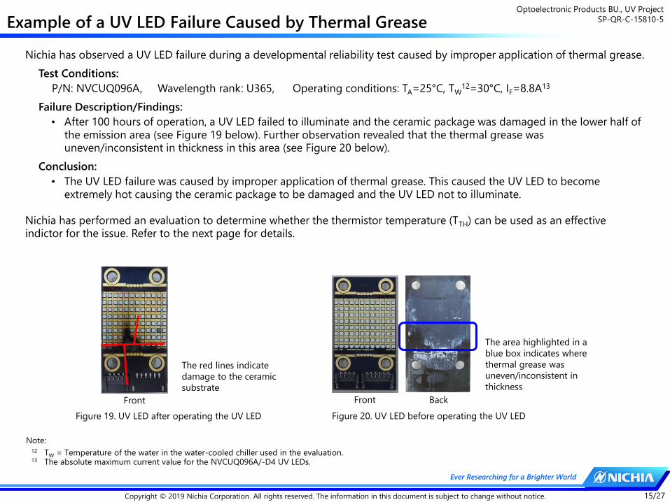
The area highlighted in a
blue box indicates where
thermal grease was
uneven/inconsistent in
thickness
Figure 20. UV LED before operating the UV LED
Front Back
Figure 19. UV LED after operating the UV LED
The red lines indicate
damage to the ceramic
substrate
Front
Note:12 TW = Temperature of the water in the water-cooled chiller used in the evaluation.13 The absolute maximum current value for the NVCUQ096A/-D4 UV LEDs.
Nichia has observed a UV LED failure during a developmental reliability test caused by improper application of thermal grease.
Test Conditions:
P/N: NVCUQ096A, Wavelength rank: U365, Operating conditions: TA=25°C, TW12=30°C, IF=8.8A13
Failure Description/Findings:
• After 100 hours of operation, a UV LED failed to illuminate and the ceramic package was damaged in the lower half of the emission area (see Figure 19 below). Further observation revealed that the thermal grease was uneven/inconsistent in thickness in this area (see Figure 20 below).
Conclusion:
• The UV LED failure was caused by improper application of thermal grease. This caused the UV LED to become extremely hot causing the ceramic package to be damaged and the UV LED not to illuminate.
Nichia has performed an evaluation to determine whether the thermistor temperature (TTH) can be used as an effective indictor for the issue. Refer to the next page for details.

Optoelectronic Products BU., UV Project
SP-QR-C-15810-5
16/27Copyright © 2019 Nichia Corporation. All rights reserved. The information in this document is subject to change without notice.
Ever Researching for a Brighter World
Evaluation for Temperature Distributions
X (Upper)
Position of the TTH
To determine if the thermistor temperature (TTH) represents how evenly or unevenly applied the thermal grease is, Nichia has performed an evaluation under the following conditions. To verify the TTH, a thermal imaging camera was used.
Evaluation Conditions:
P/N: NVCUQ096A, Wavelength rank: U365, Operating conditions: TA=25°C, TW=25°C, IF=8A
Evaluation Results:
• When an uneven application of thermal grease occurred only in the upper half of the emission area, the TTH was very similar to the TTH for the UV LED with an even application (i.e. TTH=46°C). See Figures 21 through 23 below.
• However, the thermal imaging camera showed that the first UV LED (i.e. with an uneven application of thermal grease) had a temperature difference of approx. 60°C between the upper and lower half area.
Conclusions/Recommendations:
• If an uneven application of thermal grease occurs in areas away from the thermistor position, it will not be detected by the thermistor.
• Sufficient verification should be performed (e.g. using a thermal imaging camera) to ensure an even and consistent application of thermal grease.
Figure 21. Thermal
grease applied with
an appropriate
stencil mask (upper)
and a thermal
image of this UV
LED in operation
(lower)
Figure 22. Thermal
grease applied only
in the lower half of
the emission area
(upper) and a
thermal image of
this UV LED in
operation (lower)
Figure 23. Thermal
grease applied only
in the upper half of
the emission area
(upper) and a
thermal image of
this UV LED in
operation (lower)
X (Lower)
• Virtually no difference in
the temperature between
the upper and lower
emission area.
• TTH ≈ 46°C
• Difference in the
temperature between the
upper and lower emission
area ≈ 60°C.
• TTH ≈ 46°C
• Difference in the
temperature between the
upper and lower emission
area ≈ 50°C.
• TTH ≈ 95°C
X (Upper)
X (Lower)
X (Upper)
X (Lower)
Position of the TTHPosition of the TTH

Optoelectronic Products BU., UV Project
SP-QR-C-15810-5
17/27Copyright © 2019 Nichia Corporation. All rights reserved. The information in this document is subject to change without notice.
Ever Researching for a Brighter World
Recommended Tightening Torques
Appearance Thermal Interface Material Tightening Torque Result
Thermal Grease
30cN・m (0.30N・m) No issue
35cN・m (0.35N・m) No issue
40cN・m (0.40N・m) No issue
45cN・m (0.45N・m) No issue
50cN・m (0.50N・m) No issue
55cN・m (0.55N・m) No issue
60cN・m (0.60N・m) No issue
M3 steel pan-head screw
Material Strength Grade Type of HeadTightening Torque (N・m)
M2 M2.6 M3 M4
Steel 4.6 Pan-head 0.12 0.25 0.43 0.98
Stainless steel A2 - 50 Pan-head 0.11 0.22 0.37 0.87
Brace ー Pan-head 0.09 0.18 0.28 0.74
Nichia has performed a tightening torque test for the UV LEDs and confirmed that that there are no issues with the following
conditions:
Recommended screw: M3 steel pan-head screw Recommended tightening torque range: 0.25 to 0.60N・m
Table 3. Results of a tightening torque test
Table 4. Tightening torques by screw type14
Note:14 The tightening torque values are only typical values and are not the specification values for the indicated screws.
Cautions/Suggestions:
Use the test results/data presented above for reference purposes only. Nichia strongly recommends performing a
verification to ensure the optimal tightening torque for the chosen application.
◦ If the tightening torque is too low, it may cause issues with heat dissipation.
◦ If the tightening torque is too high, it may cause the ceramic substrate to be damaged.
◦ The optimal tightening torque varies depending on the material of the screw being used.

Optoelectronic Products BU., UV Project
SP-QR-C-15810-5
18/27Copyright © 2019 Nichia Corporation. All rights reserved. The information in this document is subject to change without notice.
Ever Researching for a Brighter World
Recommended Screw Tightening Order
• The diameter of the reference screw hole (i.e. screw hole circled in red in Figure 25 below) is designed to be smaller than
those of the other holes (i.e. screw holes circled in light blue in Figure 25 below) to ensure that the reference screw is easy
to identify.
Screw hole diameters:
Reference screw hole: ⌀ 3.2cm
Screw holes: ⌀ 3.6cm
Damage around the
reference screw hole due to
incorrect tightening order.
• The screw holes are designed with a larger tolerance for easy insertion when
attaching the UV LEDs to a heatsink and the aligning holes for the assembly.
However, if the first screw is tightened in one of the three larger screw holes
before the screw is tightened in the reference screw hole, it may cause the UV
LED to move resulting in a misalignment between the reference screw hole and
the hole in the heatsink; in some cases, this could cause the ceramic substrate
to be damaged (see Figure 24 below). Ensure that when attaching the UV LEDs
to a heatsink, tighten the screw in the reference screw hole first.
• Nichia recommends tightening the screws in the order indicated by the arrows
in Figure 25.
Figure 24. Example of damage to the ceramic substrate
Figure 25. Screw hole positions
Reference
Screw Hole

Optoelectronic Products BU., UV Project
SP-QR-C-15810-5
19/27Copyright © 2019 Nichia Corporation. All rights reserved. The information in this document is subject to change without notice.
Ever Researching for a Brighter World
When tightening a screw with a washer/spring lock washer (a.k.a. split washer, spring lock washer), ensure that it does not
damage the ceramic substrate.
Nichia has performed an evaluation test and confirmed that:
• if a M3 screw is secured using both a spring washer and washer, it does not damage the ceramic substrate.
• if the washer diameter is ⌀7mm, it can touch the solder joints of the connecting device.
Based on reports from customers, Nichia is aware that:
• if a screw is secured only using a spring washer without a washer under it, it can damage the ceramic substrate.
Cautions/Suggestions:
Washer size:
• If the washer touches the solder joints of the connecting device, it may cause serious injury or death (e.g. electrical
shock). Nichia has confirmed that washers with a diameter of ⌀6mm did not cause this issue.
Use of spring washers:
• Spring washers are shaped like a spiral and one of the edges is raised to create resistance to rotation. This may cause
excessive force on the ceramic substrate when a washer is not used with the spring washer. Ensure that spring
washers are used properly with washers.
Precautions for Using Washers/Spring Washers
Figure 26. Example of using a spring washer
and ⌀6mm washer
Figure 27. Example of using a spring washer
and ⌀7mm washer
Figure 28. Example of using a
spring washer without a washer
The ⌀7mm washer is in contact with the solder joints of the connecting device.

Optoelectronic Products BU., UV Project
SP-QR-C-15810-5
20/27Copyright © 2019 Nichia Corporation. All rights reserved. The information in this document is subject to change without notice.
Ever Researching for a Brighter World
Assembly/Handling Precautions for the NVCUQ048A/072A/096A(-D4) UV LEDs
Handling Precautions with Tweezers Miscellaneous
CAUTION: Do not stack the UV LEDs on top each other.CAUTION: Ensure that the tweezers do not damage the LED (e.g. lens).
• Do not stack the UV LEDs on top of one another, regardless of
whether the UV LEDs are attached to heatsinks or not. Otherwise, it
may cause damage to the lens and the ceramic substrate (e.g. cuts,
scratches, chips, cracks, delamination, and deformation) and the wire
to break causing a catastrophic failure (i.e. the UV LED not to
illuminate).
• Nichia recommends using special tweezers (e.g. vacuum tweezers) to
handle the UV LEDs. However, use care to ensure:
◦ the tweezers do not touch the lens,
◦ excessive force is not applied to the UV LED.
Otherwise, it may cause damage to the lens and/or the ceramic
substrate (e.g. cuts, scratches, chips, cracks, delamination, and
deformation) and the wire to break causing a catastrophic failure (i.e.
the UV LED not to illuminate).
Assembly Precautions Handling Precautions with Bare hands
• Ensure that the nozzle does not come in contact with the lens when it
picks up the UV LED. If this occurs, it may cause damage to the lens
(e.g. cuts, scratches, chips, cracks, delamination, and deformation) and
the wire to break causing a catastrophic failure (i.e. the UV LED not to
illuminate).
• The nozzle should only touch the ceramic substrate to hold the UV LED.
• Do not handle the UV LEDs with bare hands:
◦ this may contaminate the UV LED surface and have an effect on the
optical characteristics,
◦ the lens may cause injuries since the edges are sharp.
• Dropping may cause damage to the lens, ceramic substrate, and in
some cases the internal wires causing a catastrophic failure (i.e. the UV
LED not to illuminate).
CAUTION: Do not drop. Handle with care.CAUTION: Do not handle the UV LEDs
with bare hands.CAUTION: Do not allow the nozzle to touch the lens.

Optoelectronic Products BU., UV Project
SP-QR-C-15810-5
21/27Copyright © 2019 Nichia Corporation. All rights reserved. The information in this document is subject to change without notice.
Ever Researching for a Brighter World
How to Insert/Remove a Socket Connector
Inserting a socket
connector
1. Place the socket
connector on the
connecting device for
initial positioning.
2. Push down the socket
connector until it is
inserted correctly.
3. If the socket connector
is successfully inserted,
a click is heard.
Reinforced Snap-fit
Snap-fit
Removing the socket
connector
1. Hold the protruding
edge portion indicated
to the left (i.e. lever).
2. Pull it up to disengage
the snap-fits closer to
the lever side.
3. Pull it up further until
the reinforced snap-fits
are fully disengaged.
Figure 29. Structure of the
connecting device (header)15 and
socket connector
Cautions when removing the socket connector:
• Do not pull the cables as it may damage the socket
connector, the header, and/or the UV LED.
• Do not remove the socket connector from the cable
side as it will not disengage the snap-fits. Doing so
may damage the socket connector, the header and/or
the UV LED.
Note:15 P/N: DF65-4P/6P manufactured by Hirose Electric Co. Ltd.
Snap-fit
Reinforced Snap-fit
Lever
Socket
Connector
Header Reinforced
Snap-fit

Optoelectronic Products BU., UV Project
SP-QR-C-15810-5
22/27Copyright © 2019 Nichia Corporation. All rights reserved. The information in this document is subject to change without notice.
Ever Researching for a Brighter World
Precautions When Using UV LEDs in a Parallel Circuit
DC16A
?A ?A
COB1 COB2
• Nichia performed a simulation with the following conditions and method to determine the effect of connecting the UV
LEDs in parallel (i.e. current divider circuit).
• Simulated Conditions:
Part Number: NVCUQ096A
Wavelength rank: U365
Junction temp.: TJ=25°C, 85°C, 130°C
Input current: IF=16A (i.e. IF=8A16 for each LED, both driven by a power supply)
• Simulation Method:
Two UV LEDs17 were connected in parallel and driven by a power supply at IF=16A
to calculate the difference in current between the two UV LEDs.Figure 30. Simulated circuit
• Simulation Result:
When the UV LED with a forward voltage (VF) of 44V was
connected with another with a 1V higher VF in parallel, the current
was split between them (i.e. current division) and the current
flowing through the first one (i.e. due to its lower VF) exceeded
the absolute maximum rating (i.e. 8.8A).
• Cautions/Suggestions:
◦ Nichia recommends designing the circuit to ensure that each
UV LED is driven by a separate power supply.
◦ If the chosen application uses the UV LEDs in a parallel circuit,
sufficient verification should be performed to ensure that there
are no issues (e.g. exceeding the absolute maximum current
due to parallel connection as shown above). If technical
assistance is required or specific issues arise during verification,
contact a local sales representative.
◦ This simulation and its results are for reference purposes only.
TJ=25°C
TJ=85°C
TJ=130°C
The red line (1.6A) indicates
where one of the two UV
LEDs exceeds the absolute
maximum current (8.8A).
Difference in the VF values between the UV LEDs (V)
Dif
fere
nce
in
cu
rren
t b
etw
een
th
e U
V L
ED
s (A
)
Note:16 IF=8A is the sorting current of the NVCUQ096A UV LEDs.17 The VF of one of these UV LEDs was set as 44V and the VF of the other one was set as 44V to 46V. The VF value 44V was used as a reference to calculate the
difference in current between the two UV LEDs.
Figure 31. Difference in Current vs. Difference in the VF
REFERENCE

Optoelectronic Products BU., UV Project
SP-QR-C-15810-5
23/27Copyright © 2019 Nichia Corporation. All rights reserved. The information in this document is subject to change without notice.
Ever Researching for a Brighter World
Peak Irradiance Measurement of a UV Irradiator (NVCUQ096A/-D4)
• Nichia performed a measurement of a UV irradiator using the NVCUQ096A-D4 UV LEDs. For the details of the
measurement conditions and the internal circuit diagram, refer to the following information. For the measurement results,
refer to Pages 24 through 27.
Figure 33. UV LED’s internal circuit diagram18
Water Cooling System Specifications:
Copper heatsink: HS-C120 (manufactured by Kawaso Texcel Co., Ltd.)
Thermal grease: TC-5622 (manufactured by Dow Corning Toray Co., Ltd.)
Tube Diameter: 10mm (inner), 12mm (outer)
Chiller22: PCU-1610R (manufactured by Apiste Corporation)
Note:18 Each UV LED has two internal circuits; each internal circuit has four arrays connected in parallel, each with 12 LED die connected in series.19 Each unit was assembled with 4 UV LEDs from the same wavelength rank.20 Size of the area highlighted by the dashed red box in Figure 30.21 Values measured at TA=25°C, IF=8A.22 Chilled water temperature TW=25°C, water flow rate=5L/min.
1 2 3 4
上下
Figure 32. Measured UV irradiator
Upper
Lower
1-上(+) TH11-下(+)
1-上(-) TH11-下(-)
2-上(+) TH22-下(+)
2-上(-) TH22-下(-)
3-上(+) TH33-下(+)
3-上(-) TH33-下(-)
4-上(+) TH44-下(+)
3-上(-) TH43-下(-)1-Upper (-) 1-Lower (-) TH1 2-Upper (-) 2-Lower (-) TH2 3-Upper (-) 3-Lower (-) TH3 4-Upper (-) 4-Lower (-) TH4
1-Upper (+) 1-Lower (+) TH1 2-Upper (+) 2-Lower (+) TH2 3-Upper (+) 3-Lower (+) TH3 4-Upper (+) 4-Lower (+) TH4
UV Irradiator Specifications:
Number or units: 4 UV irradiators19
Size of the emitting area20: 20 x 100mm
Unit 1: 4 NVCUQ096A (U365) LEDs, Radiant flux21: Avg. 144W
Unit 2: 4 NVCUQ096A (U385) LEDs, Radiant flux21: Avg. 160W
Unit 3: 4 NVCUQ096A-D4 (U365) LEDs, Radiant flux21: Avg. 128W
Unit 4: 4 NVCUQ096A-D4 (U385) LEDs, Radiant flux21: Avg. 155W
REFERENCE

Optoelectronic Products BU., UV Project
SP-QR-C-15810-5
24/27Copyright © 2019 Nichia Corporation. All rights reserved. The information in this document is subject to change without notice.
Ever Researching for a Brighter World
Peak Irradiance Measurement of a UV Irradiator - Results (Unit 1)
Current per LED
Die24 [mA]
Thermistor
Temp.25 [°C]
Junction Temp.25
[°C]
250 30.7 34.2
500 37.1 44.6
1000 51.6 67.6
Table 5. Current vs. temperature (TTH/TJ) data
Figure 34. Peak irradiance vs. working distance by Current23
• The following results shown in Figure 34 below were obtained from the measurement of a UV irradiator using U365
NVCUQ096A UV LEDs23. For the temperature data of the UV irradiator with the heat dissipation conditions used, refer to
Table 5. For the details of the UV irradiator specifications and heat dissipation conditions used in the measurement, see
Page 23. For information on how to calculate the TJ, see Pages 9 and 10.
WD=0mm was set at the same
level as the UV LED assembly
(i.e. heatsink) surface.
Irradiated Target
Surface
Assembly (heatsink)
Surface
Working
Distance
Figure 35. Definition for the working distance (WD)
Note:23 The measurement was performed with the UV Power Puck® II (manufactured by Electronic Instrumentation & Technology, Inc.).24 The current values per LED die were calculated based on the current value input to the measured UV LEDs assuming the UV LED consists only of LED die with the
same VF.25 Both the thermistor temperatures and the junction temperatures are average values of the four UV LEDs used in the measured UV irradiator.
Working Distance (mm)
Peak I
rrad
ian
ce (
W/c
m2)
250mA per die
500mA per die
1000mA per die
REFERENCE

Optoelectronic Products BU., UV Project
SP-QR-C-15810-5
25/27Copyright © 2019 Nichia Corporation. All rights reserved. The information in this document is subject to change without notice.
Ever Researching for a Brighter World
Peak Irradiance Measurement of a UV Irradiator - Results (Unit 2)
Current per LED
Die27 [mA]
Thermistor
Temp.28 [°C]
Junction Temp.28
[°C]
250 29.8 33.1
500 35.2 42.1
1000 47.6 62.3
Table 6. Current vs. temperature (TTH/TJ) data
Figure 36. Peak irradiance vs. working distance by Current26
WD=0mm was set at the same
level as the UV LED assembly
(i.e. heatsink) surface.
Irradiated Target
Surface
Assembly (heatsink)
Surface
Working
Distance
Figure 37. Definition for the working distance (WD)
• The following results shown in Figure 36 below were obtained from the measurement of a UV irradiator using U385
NVCUQ096A UV LEDs26. For the temperature data of the UV irradiator with the heat dissipation conditions used, refer to
Table 6. For the details of the UV irradiator specifications and heat dissipation conditions used in the measurement, see
Page 23. For information on how to calculate the TJ, see Pages 9 and 10.
Note:26 The measurement was performed with the UV Power Puck® II (manufactured by Electronic Instrumentation & Technology, Inc.). 27 The current values per LED die were calculated based on the current value input to the measured UV LEDs assuming the UV LED consists only of LED die with the
same VF.28 Both the thermistor temperatures and the junction temperatures are average values of the four UV LEDs used in the measured UV irradiator.
Working Distance (mm)
Peak I
rrad
ian
ce (
W/c
m2)
250mA per die
500mA per die
1000mA per die
REFERENCE

Optoelectronic Products BU., UV Project
SP-QR-C-15810-5
26/27Copyright © 2019 Nichia Corporation. All rights reserved. The information in this document is subject to change without notice.
Ever Researching for a Brighter World
Peak Irradiance Measurement of a UV Irradiator - Results (Unit 3)
Current per LED
Die30 [mA]
Thermistor
Temp.31 [°C]
Junction Temp.31
[°C]
250 29.2 32.8
500 35.9 43.5
1000 50.4 66.6
Table 7. Current vs. temperature (TTH/TJ) data
Figure 38. Peak irradiance vs. working distance by Current29
WD=0mm was set at the same
level as the UV LED assembly
(i.e. heatsink) surface.
Irradiated Target
Surface
Assembly (heatsink)
Surface
Working
Distance
Figure 39. Definition for the working distance (WD)
Working Distance (mm)
Peak I
rrad
ian
ce (
W/c
m2)
250mA per die
500mA per die
1000mA per die
• The following results shown in Figure 38 below were obtained from the measurement of a UV irradiator using U365
NVCUQ096A-D4 UV LEDs29. For the temperature data of the UV irradiator with the heat dissipation conditions used, refer to
Table 7. For the details of the UV irradiator specifications and heat dissipation conditions used in the measurement, see
Page 23. For information on how to calculate the TJ, see Pages 9 and 10.
Note:29 The measurement was performed with the UV Power Puck® II (manufactured by Electronic Instrumentation & Technology, Inc.). Since the measurement
equipment is only capable of reading up to 20W/cm2, the measurement results shown in Figure 38 include both data based on actual readings (i.e. solid line) and estimated readings (i.e. dashed line).
30 The current values per LED die were calculated based on the current value input to the measured UV LEDs assuming the UV LED consists only of LED die with the same VF.
31 Both the thermistor temperatures and the junction temperatures are average values of the four UV LEDs used in the measured UV irradiator.
REFERENCE

Optoelectronic Products BU., UV Project
SP-QR-C-15810-5
27/27Copyright © 2019 Nichia Corporation. All rights reserved. The information in this document is subject to change without notice.
Ever Researching for a Brighter World
Peak Irradiance Measurement of a UV Irradiator - Results (Unit 4)
Current per LED
Die33 [mA]
Thermistor
Temp.34 [°C]
Junction Temp.34
[°C]
250 29.8 33.1
500 35.7 42.8
1000 48.4 63.3
Table 8. Current vs. temperature (TTH/TJ) data
Figure 40. Peak irradiance vs. working distance by Current32
WD=0mm was set at the same
level as the UV LED assembly
(i.e. heatsink) surface.
Irradiated Target
Surface
Assembly (heatsink)
Surface
Working
Distance
Figure 41. Definition for the working distance (WD)
Working Distance (mm)
Peak I
rrad
ian
ce (
W/c
m2)
250mA per die
500mA per die
1000mA per die
• The following results shown in Figure 40 below were obtained from the measurement of a UV irradiator using U385
NVCUQ096A-D4 UV LEDs32. For the temperature data of the UV irradiator with the heat dissipation conditions used, refer to
Table 8. For the details of the UV irradiator specifications and heat dissipation conditions used in the measurement, see
Page 23. For information on how to calculate the TJ, see Pages 9 and 10.
Note:32 The measurement was performed with the UV Power Puck® II (manufactured by Electronic Instrumentation & Technology, Inc.). Since the measurement
equipment is only capable of reading up to 20W/cm2, the measurement results shown in Figure 40 include both data based on actual readings (i.e. solid line) and estimated readings (i.e. dashed line).
33 The current values per LED die were calculated based on the current value input to the measured UV LEDs assuming the UV LED consists only of LED die with the same VF.
34 Both the thermistor temperatures and the junction temperatures are average values of the four UV LEDs used in the measured UV irradiator.
REFERENCE

Optoelectronic Products BU., UV Project
SP-QR-C-15810-5
28/27Copyright © 2019 Nichia Corporation. All rights reserved. The information in this document is subject to change without notice.
Ever Researching for a Brighter World
• Nichia performed a measurement of a UV irradiator using the NVCUQ072A-D4 UV LEDs. For the details of the
measurement conditions and the internal circuit diagram, refer to the following information. For the measurement results,
refer to Pages 29 through 32.
Figure 43. UV LED’s internal circuit diagram35
Water Cooling System Specifications:
Copper heatsink: HS-C120 (manufactured by Kawaso Texcel Co., Ltd.)
Thermal grease: TC-5622 (manufactured by Dow Corning Toray Co., Ltd.)
Tube Diameter: 10mm (inner), 12mm (outer)
Chiller39: PCU-1610R (manufactured by Apiste Corporation)
Note:35 Each UV LED has two internal circuits; each internal circuit has three arrays connected in parallel, each with 12 LED die connected in series.36 Each unit was assembled with 4 UV LEDs from the same wavelength rank.37 Size of the area highlighted by the dashed red box in Figure 30.38 Values measured at TA=25°C, IF=6A.39 Chilled water temperature TW=25°C, water flow rate=5L/min.
1 2 3 4
上下
Figure 42. Measured UV irradiator
Upper
Lower
1-Upper (-) 1-Lower (-) TH1 2-Upper (-) 2-Lower (-) TH2 3-Upper (-) 3-Lower (-) TH3 4-Upper (-) 4-Lower (-) TH4
1-Upper (+) 1-Lower (+) TH1 2-Upper (+) 2-Lower (+) TH2 3-Upper (+) 3-Lower (+) TH3 4-Upper (+) 4-Lower (+) TH4
UV Irradiator Specifications:
Number or units: 4 UV irradiators36
Size of the emitting area37: 20 x 100mm
Unit 5: 4 NVCUQ072A (U365) LEDs, Radiant flux38: Avg. 103W
Unit 6: 4 NVCUQ072A (U385) LEDs, Radiant flux38: Avg. 128W
Unit 7: 4 NVCUQ072A-D4 (U365) LEDs, Radiant flux38: Avg. 93W
Unit 8: 4 NVCUQ072A-D4 (U385) LEDs, Radiant flux38: Avg. 109W
REFERENCE
Peak Irradiance Measurement of a UV Irradiator (NVCUQ072A/-D4)

Optoelectronic Products BU., UV Project
SP-QR-C-15810-5
29/27Copyright © 2019 Nichia Corporation. All rights reserved. The information in this document is subject to change without notice.
Ever Researching for a Brighter World
Peak Irradiance Measurement of a UV Irradiator - Results (Unit 5)
Current per LED
Die41 [mA]
Thermistor
Temp.42 [°C]
Junction Temp.42
[°C]
250 28.0 33.1
500 31.6 42.3
1000 39.8 62.6
Table 9. Current vs. temperature (TTH/TJ) data
Figure 44. Peak irradiance vs. working distance by Current35
• The following results shown in Figure 44 below were obtained from the measurement of a UV irradiator using U365
NVCUQ072A UV LEDs40. For the temperature data of the UV irradiator with the heat dissipation conditions used, refer to
Table 9. For the details of the UV irradiator specifications and heat dissipation conditions used in the measurement, see
Page 28. For information on how to calculate the TJ, see Pages 9 and 10.
WD=0mm was set at the same
level as the UV LED assembly
(i.e. heatsink) surface.
Irradiated Target
Surface
Assembly (heatsink)
Surface
Working
Distance
Figure 45. Definition for the working distance (WD)
Note:40 The measurement was performed with the UV Power Puck® II (manufactured by Electronic Instrumentation & Technology, Inc.).41 The current values per LED die were calculated based on the current value input to the measured UV LEDs assuming the UV LED consists only of LED die with the
same VF.42 Both the thermistor temperatures and the junction temperatures are average values of the four UV LEDs used in the measured UV irradiator.
Working Distance (mm)
Peak I
rrad
ian
ce (
W/c
m2) 250mA per die
500mA per die
1000mA per die
REFERENCE

Optoelectronic Products BU., UV Project
SP-QR-C-15810-5
30/27Copyright © 2019 Nichia Corporation. All rights reserved. The information in this document is subject to change without notice.
Ever Researching for a Brighter World
Peak Irradiance Measurement of a UV Irradiator - Results (Unit 6)
Current per LED
Die44 [mA]
Thermistor
Temp45 [°C]
Junction Temp.45
[°C]
250 27.5 32.3
500 30.6 40.7
1000 37.9 59.6
Table 10. Current vs. temperature (TTH/TJ) data
Figure 46. Peak irradiance vs. working distance by Current38
• The following results shown in Figure 46 below were obtained from the measurement of a UV irradiator using U385
NVCUQ072A UV LEDs43. For the temperature data of the UV irradiator with the heat dissipation conditions used, refer to
Table 10. For the details of the UV irradiator specifications and heat dissipation conditions used in the measurement, see
Page 28. For information on how to calculate the TJ, see Pages 9 and 10.
WD=0mm was set at the same
level as the UV LED assembly
(i.e. heatsink) surface.
Irradiated Target
Surface
Assembly (heatsink)
Surface
Working
Distance
Figure 47. Definition for the working distance (WD)
Note:43 The measurement was performed with the UV Power Puck® II (manufactured by Electronic Instrumentation & Technology, Inc.).44 The current values per LED die were calculated based on the current value input to the measured UV LEDs assuming the UV LED consists only of LED die with the
same VF.45 Both the thermistor temperatures and the junction temperatures are average values of the four UV LEDs used in the measured UV irradiator.
Working Distance (mm)
Peak I
rrad
ian
ce (
W/c
m2)
250mA per die
500mA per die
1000mA per die
REFERENCE

Optoelectronic Products BU., UV Project
SP-QR-C-15810-5
31/27Copyright © 2019 Nichia Corporation. All rights reserved. The information in this document is subject to change without notice.
Ever Researching for a Brighter World
Peak Irradiance Measurement of a UV Irradiator - Results (Unit 7)
Current per LED
Die47 [mA]
Thermistor
Temp.48 [°C]
Junction Temp.48
[°C]
250 28.5 33.8
500 32.4 43.3
1000 41.4 64.7
Table 11. Current vs. temperature (TTH/TJ) data
Figure 48. Peak irradiance vs. working distance by Current41
WD=0mm was set at the same
level as the UV LED assembly
(i.e. heatsink) surface.
Irradiated Target
Surface
Assembly (heatsink)
Surface
Working
Distance
Figure 49. Definition for the working distance (WD)
Working Distance (mm)
Peak I
rrad
ian
ce (
W/c
m2)
250mA per die
500mA per die
1000mA per die
• The following results shown in Figure 48 below were obtained from the measurement of a UV irradiator using U365
NVCUQ072A-D4 UV LEDs46. For the temperature data of the UV irradiator with the heat dissipation conditions used, refer to
Table 11. For the details of the UV irradiator specifications and heat dissipation conditions used in the measurement, see
Page 28. For information on how to calculate the TJ, see Pages 9 and 10.
Note:46 The measurement was performed with the UV Power Puck® II (manufactured by Electronic Instrumentation & Technology, Inc.). Since the measurement
equipment is only capable of reading up to 20W/cm2, the measurement results shown in Figure 48 include both data based on actual readings (i.e. solid line) and estimated readings (i.e. dashed line).
47 The current values per LED die were calculated based on the current value input to the measured UV LEDs assuming the UV LED consists only of LED die with the same VF.
48 Both the thermistor temperatures and the junction temperatures are average values of the four UV LEDs used in the measured UV irradiator.
REFERENCE

Optoelectronic Products BU., UV Project
SP-QR-C-15810-5
32/27Copyright © 2019 Nichia Corporation. All rights reserved. The information in this document is subject to change without notice.
Ever Researching for a Brighter World
Peak Irradiance Measurement of a UV Irradiator - Results (Unit 8)
Current per LED
Die50 [mA]
Thermistor
Temp.51 [°C]
Junction Temp.51
[°C]
250 28.1 33.1
500 31.6 42.1
1000 39.7 61.8
Table 12. Current vs. temperature (TTH/TJ) data
Figure 50. Peak irradiance vs. working distance by Current44
WD=0mm was set at the same
level as the UV LED assembly
(i.e. heatsink) surface.
Irradiated Target
Surface
Assembly (heatsink)
Surface
Working
Distance
Figure 51. Definition for the working distance (WD)
Working Distance (mm)
Peak I
rrad
ian
ce (
W/c
m2)
250mA per die
500mA per die
1000mA per die
• The following results shown in Figure 50 below were obtained from the measurement of a UV irradiator using U385
NVCUQ072A-D4 UV LEDs49. For the temperature data of the UV irradiator with the heat dissipation conditions used, refer to
Table 12. For the details of the UV irradiator specifications and heat dissipation conditions used in the measurement, see
Page 28. For information on how to calculate the TJ, see Pages 9 and 10.
Note:49 The measurement was performed with the UV Power Puck® II (manufactured by Electronic Instrumentation & Technology, Inc.). Since the measurement
equipment is only capable of reading up to 20W/cm2, the measurement results shown in Figure 50 include both data based on actual readings (i.e. solid line) and estimated readings (i.e. dashed line).
50 The current values per LED die were calculated based on the current value input to the measured UV LEDs assuming the UV LED consists only of LED die with the same VF.
51 Both the thermistor temperatures and the junction temperatures are average values of the four UV LEDs used in the measured UV irradiator.
REFERENCE

Optoelectronic Products BU., UV Project
SP-QR-C-15810-5
33/27Copyright © 2019 Nichia Corporation. All rights reserved. The information in this document is subject to change without notice.
Ever Researching for a Brighter World
• Nichia performed a measurement of a UV irradiator using the NVCUQ048A-D4 UV LEDs. For the details of the
measurement conditions and the internal circuit diagram, refer to the following information. For the measurement results,
refer to Pages 34 through 37.
Figure 53. UV LED’s internal circuit diagram52
Water Cooling System Specifications:
Copper heatsink: HS-C120 (manufactured by Kawaso Texcel Co., Ltd.)
Thermal grease: TC-5622 (manufactured by Dow Corning Toray Co., Ltd.)
Tube Diameter: 10mm (inner), 12mm (outer)
Chiller56: PCU-1610R (manufactured by Apiste Corporation)
Note:52 Each UV LED has two internal circuits; each internal circuit has two arrays connected in parallel, each with 12 LED die connected in series.53 Each unit was assembled with 4 UV LEDs from the same wavelength rank.54 Size of the area highlighted by the dashed red box in Figure 30.55 Values measured at TA=25°C, IF=4A.56 Chilled water temperature TW=25°C, water flow rate=5L/min.
1 2 3 4
上下
Figure 52. Measured UV irradiator
Upper
Lower
1-Upper (-) 1-Lower (-) TH1 2-Upper (-) 2-Lower (-) TH2 3-Upper (-) 3-Lower (-) TH3 4-Upper (-) 4-Lower (-) TH4
1-Upper (+) 1-Lower (+) TH1 2-Upper (+) 2-Lower (+) TH2 3-Upper (+) 3-Lower (+) TH3 4-Upper (+) 4-Lower (+) TH4
UV Irradiator Specifications:
Number or units: 4 UV irradiators53
Size of the emitting area54: 20 x 100mm
Unit 9: 4 NVCUQ048A (U365) LEDs, Radiant flux55: Avg. 68W
Unit 10: 4 NVCUQ048A (U385) LEDs, Radiant flux55: Avg. 79W
Unit 11: 4 NVCUQ048A-D4 (U365) LEDs, Radiant flux55: Avg. 62W
Unit 12: 4 NVCUQ048A-D4 (U385) LEDs, Radiant flux55: Avg. 72W
REFERENCE
Peak Irradiance Measurement of a UV Irradiator (NVCUQ048A/-D4)

Optoelectronic Products BU., UV Project
SP-QR-C-15810-5
34/27Copyright © 2019 Nichia Corporation. All rights reserved. The information in this document is subject to change without notice.
Ever Researching for a Brighter World
Peak Irradiance Measurement of a UV Irradiator - Results (Unit 9)
Current per LED
Die58 [mA]
Thermistor
Temp.59 [°C]
Junction Temp.59
[°C]
250 26.4 30.8
500 29.1 38.5
1000 34.2 54.1
Table 13. Current vs. temperature (TTH/TJ) data
Figure 54. Peak irradiance vs. working distance by Current52
• The following results shown in Figure 54 below were obtained from the measurement of a UV irradiator using U365
NVCUQ048A UV LEDs57. For the temperature data of the UV irradiator with the heat dissipation conditions used, refer to
Table 13. For the details of the UV irradiator specifications and heat dissipation conditions used in the measurement, see
Page 33. For information on how to calculate the TJ, see Pages 9 and 10.
WD=0mm was set at the same
level as the UV LED assembly
(i.e. heatsink) surface.
Irradiated Target
Surface
Assembly (heatsink)
Surface
Working
Distance
Figure 55. Definition for the working distance (WD)
Note:57 The measurement was performed with the UV Power Puck® II (manufactured by Electronic Instrumentation & Technology, Inc.).58 The current values per LED die were calculated based on the current value input to the measured UV LEDs assuming the UV LED consists only of LED die with the
same VF.59 Both the thermistor temperatures and the junction temperatures are average values of the four UV LEDs used in the measured UV irradiator.
Working Distance (mm)
Peak I
rrad
ian
ce (
W/c
m2)
250mA per die
500mA per die
1000mA per die
REFERENCE

Optoelectronic Products BU., UV Project
SP-QR-C-15810-5
35/27Copyright © 2019 Nichia Corporation. All rights reserved. The information in this document is subject to change without notice.
Ever Researching for a Brighter World
Peak Irradiance Measurement of a UV Irradiator - Results (Unit 10)
Current per LED
Die61 [mA]
Thermistor
Temp.62 [°C]
Junction Temp.62
[°C]
250 26.4 30.7
500 28.3 37.2
1000 32.7 51.8
Table 14. Current vs. temperature (TTH/TJ) data
Figure 56. Peak irradiance vs. working distance by Current55
• The following results shown in Figure 56 below were obtained from the measurement of a UV irradiator using U385
NVCUQ048A UV LEDs60. For the temperature data of the UV irradiator with the heat dissipation conditions used, refer to
Table 14. For the details of the UV irradiator specifications and heat dissipation conditions used in the measurement, see
Page 33. For information on how to calculate the TJ, see Pages 9 and 10.
WD=0mm was set at the same
level as the UV LED assembly
(i.e. heatsink) surface.
Irradiated Target
Surface
Assembly (heatsink)
Surface
Working
Distance
Figure 57. Definition for the working distance (WD)
Note:60 The measurement was performed with the UV Power Puck® II (manufactured by Electronic Instrumentation & Technology, Inc.).61 The current values per LED die were calculated based on the current value input to the measured UV LEDs assuming the UV LED consists only of LED die with the
same VF.62 Both the thermistor temperatures and the junction temperatures are average values of the four UV LEDs used in the measured UV irradiator.
Working Distance (mm)
Peak I
rrad
ian
ce (
W/c
m2)
250mA per die
500mA per die
1000mA per die
REFERENCE
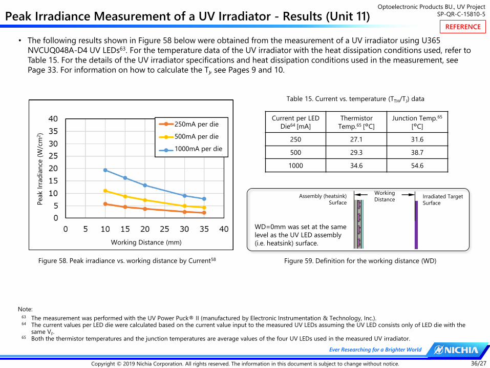
Optoelectronic Products BU., UV Project
SP-QR-C-15810-5
36/27Copyright © 2019 Nichia Corporation. All rights reserved. The information in this document is subject to change without notice.
Ever Researching for a Brighter World
Peak Irradiance Measurement of a UV Irradiator - Results (Unit 11)
Current per LED
Die64 [mA]
Thermistor
Temp.65 [°C]
Junction Temp.65
[°C]
250 27.1 31.6
500 29.3 38.7
1000 34.6 54.6
Table 15. Current vs. temperature (TTH/TJ) data
Figure 58. Peak irradiance vs. working distance by Current58
• The following results shown in Figure 58 below were obtained from the measurement of a UV irradiator using U365
NVCUQ048A-D4 UV LEDs63. For the temperature data of the UV irradiator with the heat dissipation conditions used, refer to
Table 15. For the details of the UV irradiator specifications and heat dissipation conditions used in the measurement, see
Page 33. For information on how to calculate the TJ, see Pages 9 and 10.
WD=0mm was set at the same
level as the UV LED assembly
(i.e. heatsink) surface.
Irradiated Target
Surface
Assembly (heatsink)
Surface
Working
Distance
Figure 59. Definition for the working distance (WD)
Note:63 The measurement was performed with the UV Power Puck® II (manufactured by Electronic Instrumentation & Technology, Inc.).64 The current values per LED die were calculated based on the current value input to the measured UV LEDs assuming the UV LED consists only of LED die with the
same VF.65 Both the thermistor temperatures and the junction temperatures are average values of the four UV LEDs used in the measured UV irradiator.
Working Distance (mm)
Peak I
rrad
ian
ce (
W/c
m2)
250mA per die
500mA per die
1000mA per die
REFERENCE

Optoelectronic Products BU., UV Project
SP-QR-C-15810-5
37/27Copyright © 2019 Nichia Corporation. All rights reserved. The information in this document is subject to change without notice.
Ever Researching for a Brighter World
Peak Irradiance Measurement of a UV Irradiator - Results (Unit 12)
Current per LED
Die67 [mA]
Thermistor
Temp.68 [°C]
Junction Temp.68
[°C]
250 26.8 31.2
500 28.9 38.0
1000 33.9 53.3
Table 16. Current vs. temperature (TTH/TJ) data
Figure 60. Peak irradiance vs. working distance by Current61
• The following results shown in Figure 60 below were obtained from the measurement of a UV irradiator using U385
NVCUQ048A-D4 UV LEDs66. For the temperature data of the UV irradiator with the heat dissipation conditions used, refer to
Table 16. For the details of the UV irradiator specifications and heat dissipation conditions used in the measurement, see
Page 33. For information on how to calculate the TJ, see Pages 9 and 10.
WD=0mm was set at the same
level as the UV LED assembly
(i.e. heatsink) surface.
Irradiated Target
Surface
Assembly (heatsink)
Surface
Working
Distance
Figure 61. Definition for the working distance (WD)
Note:66 The measurement was performed with the UV Power Puck® II (manufactured by Electronic Instrumentation & Technology, Inc.).67 The current values per LED die were calculated based on the current value input to the measured UV LEDs assuming the UV LED consists only of LED die with the
same VF.68 Both the thermistor temperatures and the junction temperatures are average values of the four UV LEDs used in the measured UV irradiator.
Working Distance (mm)
Peak I
rrad
ian
ce (
W/c
m2)
250mA per die
500mA per die
1000mA per die
REFERENCE