part one concrete behavior - civil engineering …civil.emu.edu.tr/courses/civl484/lecture notes...
TRANSCRIPT

Part One
Concrete Behavior


Part one-CONCRETE BEHAVIOR

Part one-CONCRETE BEHAVIOR
Undesirable behavior for concrete:
Disintegration
Spalling
Cracking
Leakage
Wear
Deflection
Settlement

Part one-CONCRETE BEHAVIOR
What can we do?
Understand the reasons of undesirable behavior.
Develop a repair strategy
What is the result?
Successful and long lasting repair

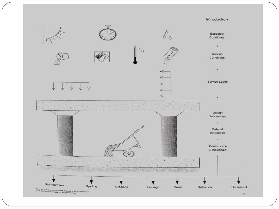
Part one-CONCRETE BEHAVIOR
Factors affecting concrete behavior
Design
Materials
Construction
Service loads
Service conditions
Exposure conditions
Most of these are combined working together

Part one-CONCRETE BEHAVIOR
Categories of discussion for concrete behavior:
Embedded metal corrosion
Disintegration
Moisture effect
Thermal effects
Load effects
Improper workmanship

Embedded metal corrosion Process

Embedded metal corrosion process
pH of fresh concrete: 12-13 (alkaline)
Passivation film around steel is formed.
Alkaline environment protects steel in concrete from
corrosion.
If passivation film is disrupted, corrosion may start.

Embedded metal corrosion Process
Electrical current flows between the cathode and anode.
Reaction results in increase in metal volume Fe (iron)
oxidized into Fe(OH)2 and Fe(OH)3 and precipitates as FeO
OH (rust color).
Water & oxygen must be present.
Poor quality concrete acclerates corrosion rate.
Reduced pH value (reduced alkalinity) causes carbonation.
Carbonation increases corrosion rate.
Agressive chemicals increases rate of corrosion.

Embedded metal corrosion Process
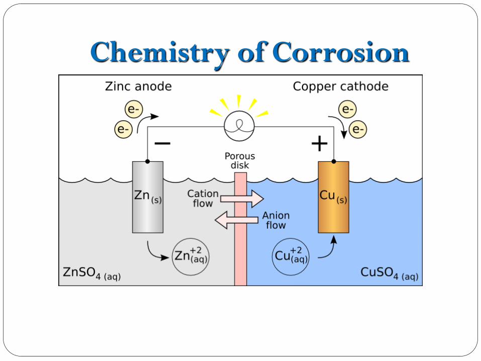
Corrosion is an electrochemical process.
Electrochemical process needs:
Anode (steel reinforcement)
Cathode (steel reinforcement)
Electrolyte (moist concrete matrix)

Chemistry of Corrosion
Anode: Zn
Cathode: Copper
Chemistry of Corrosion

Reinforcement Corrosion Reactions
Passivating Layer
Oxidation:
2Fe(s) 2Fe2+ (aq)) + 4e-
Fe2+ + 2(OH)- Fe(OH)2
4Fe(OH)2 + O2 +2H2O 4Fe(OH)3
Reduction:
2H2O+O2+4e- 4(OH)-
Anode Cathode
e- e-
Cathode
Fe+ Fe+ OH- OH-
H2O, O2
H2O, O2

Embedded metal corrosion Process

Corrosion induced cracking and spalling
Factors causing cracking and spalling:
Concrete tensile strength
Quality of concrete cover over the reinforcing bar
Bond or condition of the interface between the rebar and
surrounding concrete
Diameter of reinforcing bar
Percentage of corrosion by weight of reinforcing bar
Cover to bar-diameter ratio (see table)

Corrosion Induced Cracking & Spalling

Reduction in Structural Capacity
Structural capacity is affected by:
1.Bar corrosion
2.Cracking of concrete sorrounding the bar
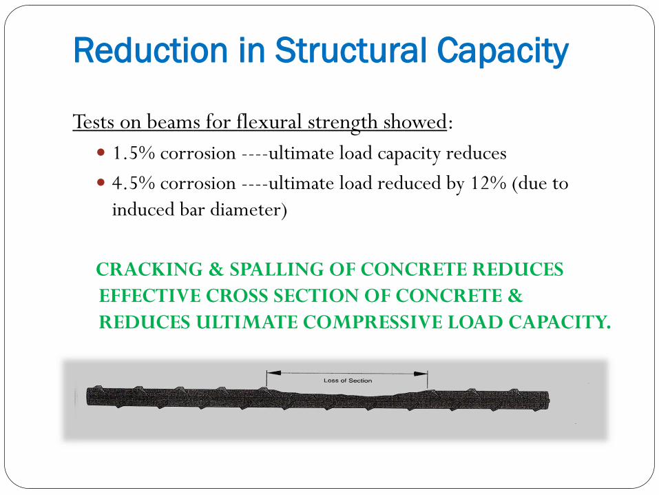
Reduction in Structural Capacity
Tests on beams for flexural strength showed:
1.5% corrosion ----ultimate load capacity reduces
4.5% corrosion ----ultimate load reduced by 12% (due to
induced bar diameter)
CRACKING & SPALLING OF CONCRETE REDUCES
EFFECTIVE CROSS SECTION OF CONCRETE &
REDUCES ULTIMATE COMPRESSIVE LOAD CAPACITY.

Chloride Penetration
Chlorides comes in concrete from environments containing
chlorides such as sea water or de-icing salts.
Penetration starts from surface and then moves inward.
Penetration takes time and depends on:
Amount of chlorides coming into contact with
concrete
Permeability of concrete
Amount of moisture present

Chloride Penetration
If chlorides penetrate into concrete, what happens?
Corrosion of steel will take place when moisture & oxygen are
present.
As rust layers build, tensile forces will generate.
Tensile forces cause expansion of oxide and concrete will crack
and delaminate.
Spalling
Occurs if natural forces of gravity or traffic wheel load act on the
loose concrete.

Chloride Penetration
If cracking & delamination progress:
Corrosive salts, oxygen, & moisture will enter into concrete
Accelerated corrosion will take place
Corrosion begins to affect rebars buried further within concrete.
Concrete pH value
8000 ppm of chloride ion with pH value of concrete 13.2 starts
corrosion.
Ph value of 11.6 would initiate corrosion with only 71 ppm of
chloride ions.

Chloride Penetration

Cracks & Chlorides
Corrosive chemicals (de-icing salts)
enter in concrete through cracks and
construction joints.
ACI presents a table for tolerable
crack widths in R/C.
Steel Corrosion: If chlorides are
present, corrosion starts even in a
high alkaline environment. Chloirdes
act as catalysts.
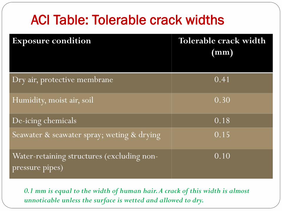
ACI Table: Tolerable crack widths
Exposure condition Tolerable crack width
(mm)
Dry air, protective membrane 0.41
Humidity, moist air, soil 0.30
De-icing chemicals 0.18
Seawater & seawater spray; weting & drying 0.15
Water-retaining structures (excluding non-
pressure pipes)
0.10
0.1 mm is equal to the width of human hair. A crack of this width is almost
unnoticable unless the surface is wetted and allowed to dry.

Cast-in Chlorides
Chlorides are in concrete already before structure
is in service.
Chlorides can also be found in some aggregates.
Aggregates from beach or sea water used as mixing
water will result in cast-in chlorides.
Chlorides are formed in two forms:
1. Water soluble form (in admixtures)-most
damaging
2. Acid soluble form ( in aggregates)

ACI 201.2R Limits of chloride ion Service condition % of Cl to weight of cement
Prestressed concrete 0.06
Conventionally reinforced concrete in a moist
environment and exposed to chloride
0.10
Conventionally reinforced concrete in a moist
environment not exposed to chloride
0.15
Above-ground building construction where
concrete will stay dry
No limit

Carbonation Carbonation is reaction between acidic gases in the atmosphere and
products of cement hydration.
Normal air: 0.03% Carbon dioxide.
Industrial atmospheres: higher carbon dioxide content
Carbon dioxide penetrates in concrete through pores & reacts with
calcium htdroxide dissolved in pore water.
This reaction reduces alkalinity of of concrete (pH of 10). Protection
around steel reinforcement is lost.
The passivity of protective layer will be destroyed.
Corrosion starts if there is moisture and oxygen and environment is
acidic or mildly alkaline.
GOOD QUALITY Concrete: Carbonation is slow (1 mm/year).
NO Carbonation: Concrete under water continuously.

Structural Steel Member Corrosion Top flange of beam is susceptible to corrosion
when a crack or construction joint intersects the
flange.
Moisture & corrosive salts are trapped on the
flange which provides an ideal environment for
corrosion.
Corrosion exerts a jacking force on concrete
above flange. When force is sufficient,
delamination will occur.

Dissimilar Metal Corrosion Corrosion can take place in concrete when two different
metals are cast along with an adequate electrode.
Moist concrete matrix is a good electrolyde.
This type of concrete is known as galvanic.
Each metal has a tendency to promote electrochemical
activity.
Gold: Active
Zinc: Inactive
List of metals in order of increasing activity: Zinc,
aluminium, steel, iron, nickel, tin, lead, brass,
copper, bronze, stainless steel, gold.
When two different melats are togetether, less active
metal will be corroded.

Dissimilar Metal Corrosion
Most common situation: Use of aluminium in reinforced
concrete.
Aluminium is used as electrical conduit or as hand rail.
Aluminium has less activity than steel.
Therefore, aluminium will corrode.
Steel will become cleaned.
Aluminium surface will grow a white oxide.
Oxide creates tensile forces that cracks sorrounding
concrete.

Post Tension Strand Corrosion
Location of unbonded strand corrosion:
1. Buildings exposed to ocean salt spray
2. Parking structures exposed to de-icing salts
Protection:
1. Protective grease
2. Sheating
Reason 1 for corrosion: If inadequate concrete cover is
damaged by heavy wheel loads, aggressive agents can penetrate
the protective system.
Reason 2 for corrosion: Poor corrosion protection of end
anchorage due to porous or cracked anchorage plug grout.
Corrosion of strands reduces cross-section and results in
increasing stress level in the strand.

SECTION 2: DISINTEGRATION MECHANISMS

Introduction to Disintegration Mechnisms
This section includes discussions of various processes which cause the constituents of concrete to;
1. Dissolve
2. Be forced to come apart through expansive volume change mechanisms
3. Become worn away through abrasion or cavitation
Depending on type of attach, concrete can soften or disintegrate (in part or whole)
Water can be one of the most aggressive environments causing disintegration.

Exposure to Aggressive Chemicals
Aggressive chemicals:
1. Inorganic acids
2. Organic acids
3. Alkaline solutions
4. Salt solutions
5. Miscellaneous
Acid attack on concrete is the reaction
between acid and calcium
hydroxide of hydrated Portland
cement.
This reaction produces water soluble
calcium compounds which are
leached away.
When limestone or dolomitic
aggregates are used the acid may
dissolve them.

Happens when following conditions are
present:
1. Freezing & thawing temperature cycles
within the concrete
2. Porous concrete that absorbs water (water-
filled pores and capillaries)
Locations:
On horizontal surfaces that are exposed to
water.
On vertical surfaces that are at the water line
in submerged portions of structures.
What happens:
Freezing water causes expansion when it is
converted into ice.

This expansion causes localized tension forces that fracture surrounding
concrete.
Fracture occurs in small pieces, working from the outer surfaces inward.
Rate of freeze-thaw deterioration is a function of following:
1. Increased porosity (increases rate)
2. Increased moisture saturation (increases rate)
3. Increased number of freeze-thaw cycles (increases rate)
4. Air entrainment (reduces rate)
5. Horizontal surfaces that trap standing water (increases rate)
6. Aggregate with small capillary structure and high absorption (increases rate)

Alkali-Aggregate Reaction These reactions (AAR) may create expansion and severe
cracking of concrete structures and pavements.
Mechanisms of reactions are not yet fully understood.
Only known that some forms of aggregates (reactive silica)
react with potassium, sodium and calcium hydroxide from
the cement and form a gel around reactive aggregates.
Gel exposed to moisture will expand.
Moisture of concrete: At least 80% relative humidity at
21-24oC.
After cracking, more moisture will enter in concrete and
alkali-aggregate reactions will be accelerated. This will also
cause freeze-that damages.

Alkali-Aggregate Reaction (AAR)
AAR can go unrecognized for some period of time (years)
before accociated severe distress will develop.
Testing of presence of alkali-aggregate reaction is conducted
by petrographic examination of concrete.
Recently, a new method capable of monitoring possible
reaction has been developed.
New method utilizes uranium acetate fluorescence technique
and is rapid and economical.

Sulfate Attack
Soluble sulfates (sodium, calcium,
magnesium) are found in areas of:
1. Mining operations
2. Chemical industries
3. Paper industries
Most common sulfates are sodium &
calcium that are found in SOILS, WATER &
INDUSTRIAL PROCESSES.
Magnesium sulfates are more destructive.
Alkali Soils or Alkali Waters:
Soils or waters containing above sulfates are
called alkali soils or alkali waters.
Sulfate Attack
Sulfates react with cement paste’s hydrated lime and hydrated
calcium aluminate.
After these reactions, solid products with volume greater that
products entering reactions will be formed.
Solid products: Gypsum & ettringite
Result: Paste expands, pressurizes and disrupts.
Further result: Surface scaling, disintegration & mass deterioration.

Improve sulfate resistance of concrete by:
Reduce water/cement ratio
Use an adequate cement factor
Use cement with low C3A including air entrainment
Make proper proportioning of silica fume, fly ash and slag.

Erosion
Cavitation causes erosion of concrete surfaces resulting from the
collapse of vapor bubbles formed by pressure changes within a
high velocity water flow.
Vapor bubbles flow downstream with the water.
When they enter a region of of higher pressure, they collapse
with great impact.
The formation of vapor bubles and their subsequent collapse is
called CAVITATION.
Energy released upon collapse of vapor bubles causes
“cavitation damage”.
Cavitation damage results in the erosion of the cement matrix.
At high velocities, forces of cavitation may be great enough to
wear away large quantites of concrete.

Cavitation damage is avioded by producing smooth surfaces & avoiding protruding obstructions to flow.
ABRASION “wearing away of the surface by rubbing and friction”.
Factors affecting abrasion resistance include:
Compressive strength
Aggregate properties
Use of toppings
Finishing methods
curing

SECTION 3: Moisture Effects
The following topics are covered in this section:
Drying Shrinkage
Moisture Vapor Transmission
Volume Change Moisture Content
Curling

Introduction to Moisture Effects
Concrete is like fresh-cut trees made into lumber.
The lumber is wet when cut, but immediately begins to dry
to a moisture level equal to the surrounding environment.
As the wood dries, it also reduces in volume and, in some
cases, splits under the stress of shrinkage.
Even seasoned wood changes volume as the moisture level in
the wood changes with seasonal variations in humidity.
Introduction to Moisture Effects
Concrete behaves in a similar fashion.
In fresh concrete, the space between the particles is
completely filled with water.
The excess water evaporates after the concrete hardens.
The loss of moisture causes the volume of the paste to
contract.
This, in turn, leads to shrinkage stress and shrinkage
cracking. Like wood, concrete also changes volume in
response to ambient humidity changes.
Part One: Concrete Behavior Section 3: Moisture Effects
Drying Shrinkage
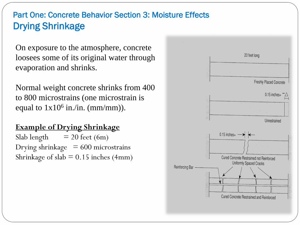
On exposure to the atmosphere, concrete
loosees some of its original water through
evaporation and shrinks.
Normal weight concrete shrinks from 400
to 800 microstrains (one microstrain is
equal to 1x106 in./in. (mm/mm)).
Example of Drying Shrinkage
Slab length = 20 feet (6m)
Drying shrinkage = 600 microstrains
Shrinkage of slab = 0.15 inches (4mm)
Drying shrinkage, if unrestrained, results in shortening of the
member without a build-up of shrinkage stress.
If the member is restrained from moving, stress build-up may
exceed the tensile strength of the concrete.
This over-stressing results in dry shrinkage cracking.
Correct placement of reinforcing steel in the number
distributing the shrinkage stresses and controls crack widths.

Factors affecting drying shrinkage
Factor Reduced Shrinkage Increased Shrinkage
Cement type type I, II
38 mm
type III
19 mm Aggregate size
Aggregate type quartz sandstone
Cement content 325 kg/m3 415 kg/m
3
Slump 76 mm 152 mm
Curing 7 days 3 days
Placement
temperature
l6OC 29
OC
Aggregate state
washed dirty

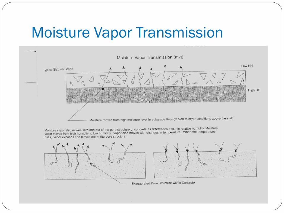
Moisture Vapor Transmission
Water vapor travels through concrete when a structural
member's surfaces are subject to different levels of relative
humidity (RH).
Moisture vapor travels from high RH to low RH.
The amount of moisture vapor transmission is a function of
the RH gradient between faces, and the permeability of the
concrete.
Moisture Vapor Transmission

Part One: Concrete Behavior Section 3: Moisture Effects
Volume Change-Moisture Content
Moist concrete that dries out will shrink,
while dry concrete that becomes moist
will expand. Concrete may follow
seasonal changes: hot, humid summers
generate higher moisture contents,
while cold, dry winters reduce moisture
contents.
Establishing values for the amount of
shrinkage or expansion caused by a
change in moisture content can be
carried out by estimating, based on dry
shrinkage values. Drying shrinkage
values are based on an initial 100
percent moisture content reduced to an
ambient relative humidity of about 50
percent.
Curling Curling is a common problem with slabs cast on grade.
Curling is caused by uneven moisture and temperature gradients across the thickness of the slab.
Curling is increased as drying shrinkage progresses.
Slab surfaces are usually dry on top, where they are exposed to air, and moist on the bottom, where they are exposed to soil.
The drier surface has a tendency to contract in length relative to the moist bottom surface.
Temperature gradients across a slab can create the same problems as moisture gradients.
The typical situation is solar heating of the slab's top surface, causing a higher temperature on this surface.
The top surface then has a tendency to grow in length relative to the bottom surface.
Stress relief occurs when the slab curls downward.

Curling on slabs

Section 4:
Thermal Effects The following topics are covered in this section:
Thermal Volume Change
Uneven Thermal Loads
Uneven Thermal Loads:
Continuous Spans
Restraint to Volume Change
Early Thermal Cracking of Freshly Placed Concrete
Thermal Movements in Existing Cracks
Uneven Thermal Loads:
Cooling Tower Shell
Fire Damage

Part One: Concrete Behavior Section 4: Thermal Effects
Introduction to Thermal Effects
The effect of temperature on concrete structures and members
is one of volume change.
The volume relationship to temperature is expressed by the
coefficient of thermal expansion/contraction.
Volume changes create stress when the concrete is restrained.
The resulting stresses can be of any type: tension,
compression, shear, etc.
The stressed conditions may result in undesirable behavior
such as cracking, spalling and excessive deflection.
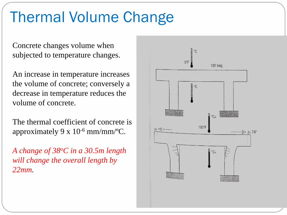
Thermal Volume Change
Concrete changes volume when
subjected to temperature changes.
An increase in temperature increases
the volume of concrete; conversely a
decrease in temperature reduces the
volume of concrete.
The thermal coefficient of concrete is
approximately 9 x 10⁻⁶ mm/mm/ºC.
A change of 38oC in a 30.5m length
will change the overall length by
22mm.

Part One: Concrete Behavior Section 4: Thermal Effects
Uneven Thermal Loads
The temperature on the surface of a deck
slab exposed to direct sunlight may reach
48oC, while the underside of the deck
may be only 26oC. A 22oC difference
known as diurnal solar heating.
This causes the top surface to have a
tendency to expand more than the bottom
surface. This results in an upward
movement during heating, and a
downward movement during cooling.
A precast double-T shaped structured
member with a 18m span can move 19mm
upward at mid-span from normal diurnal
solar heating, causing the ends to rotate
and stress the ledger beam bearing pads
and concrete.
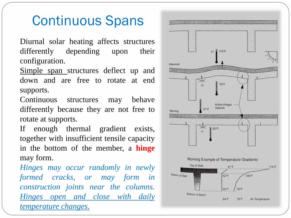
Continuous Spans
Diurnal solar heating affects structures
differently depending upon their
configuration.
Simple span structures deflect up and
down and are free to rotate at end
supports.
Continuous structures may behave
differently because they are not free to
rotate at supports.
If enough thermal gradient exists,
together with insufficient tensile capacity
in the bottom of the member, a hinge
may form.
Hinges may occur randomly in newly
formed cracks, or may form in
construction joints near the columns.
Hinges open and close with daily
temperature changes.

Part One: Concrete Behavior Section 4: Thermal Effects
Restraint to Volume Changes
If a structural member is free to deform as a result of changes
in temperature, moisture, or loads, there is no build-up of
internal stress.
If the structural member is restrained, stress build-up occurs
and can be very significant.
When stress build-up is relieved, it will occur in the weakest
portion of the structural member or its connection to other
parts of the structure.
The stress may result in tension cracks, shear cracks, and
buckling.

Early Thermal Cracking of Freshly
Placed Concrete
Freshly placed concrete undergoes a
temperature rise from the heat generated by
the cement hydration.
The heat rise occurs over the first few hours
or days after casting, then cools to the
surrounding ambient temperature. When
cooling takes place two or three days after
casting, the concrete has very little tensile
strength.
Weak tensile strength, coupled with a
thermally contracting member, provide for
the likelihood of tension cracks.

Early Thermal Cracking of Freshly
Placed Concrete Factors affecting early temperature rise include:
1. Initial temperature of materials. Warm materials lead to warm concrete. Aggregate
temperature is the most critical.
2 Ambient temperature. Higher ambient temperatures lead to higher peaks.
3. Dimensions. Larger sections generate more heat.
4. Curing. Water curing dissipates the build-up of heat. Thermal shocking should be avoided.
5 Formwork removal time. Early removal of formwork reduces peak temperature.
6. Type of formwork. Wood forms produce higher temperatures than steel forms.
7. Cement content. More cement in the mix means more heat.
8. Cement type. Type III (High Early Strength PC) cement produces more heat than most
other cements used.
9. Cement replacements. Fly ash reduces the amount of heat build-up.

Part One: Concrete Behavior Section 4: Thermal Effects
Thermal Movements in Existing Cracks
Thermal stresses can be relieved
in ways other than by the
formation of cracks.
Cracks that were formed via other
mechanisms, such as dry
shrinkage cracking, may provide
a location in the member where
thermal change strain can be
absorbed.
The crack moves with the same
cycle as the temperature cycle in
the concrete member.
Thermal movement taken up by
these cracks reduces the
movement at planned expansion
joints.

Uneven Thermal Loads
Cooling Tower Shell Large exposed cooling towers can undergo uneven
thermal stresses as the sun makes its way from east to
west.
The cooling tower has a relatively thin concrete shell,
which is easily heated by the sun.
The sun's rays hit only about 50 percent of the tower's
shell at any one time.
The portion of the tower that is being heated expands
in size relative to the cool side of the tower.
An egg-shaped cross section is formed, which moves
as the sun moves, heating other portions of the tower.
Problems may occur in portions of the tower where
rigid framing is connected to the constantly moving
outer shell.

Part One: Concrete Behavior Section 4: Thermal Effects
Fire Damage
Part One: Concrete Behavior Section 4: Thermal Effects
Fire Damage Fire affects concrete in extreme ways, some of which are listed below:
1. Uneven volume changes in affected members, resulting in distortion, buckling, and cracking. The temperature gradients are extreme: from ambient 21̊C, to higher than 800̊C at the source of the fire and near the surface.
2. Spalling of rapidly expanding concrete surfaces from extreme heat near the source of the fire. Some aggregates expand in bursts, spalling the adjacent matrix. Moisture rapidly changes to steam, causing localized bursting of small pieces of concrete.
3. The cement mortar converts to quicklime at temperatures of 400̊C, thereby causing disintegration of the concrete.
4. Reinforcing steel loses tensile capacity as the temperature rises.
5. Once the reinforcing steel is exposed by the spalling action, the steel expands more rapidly than the surrounding concrete, causing buckling and loss of bond to adjacent concrete where the reinforcement is fully encased.

Part One: Concrete Behavior Section 5: Load Effects
Section 5: Load Effects
The following topics are covered in this section:
Reinforced Concrete: Basic Engineering Principles
Cracking Modes: Continuous Span
Slab/Beam-to-Column Shear
Cantilevered Members
Continuous Structures
Columns
Post-Tensioned Members
Cylindrical Structures: Buried Pipe
Cylindrical Structures: Tanks
Connections: Contact Loading

Introduction to Load Effects
Introduction to Load Effects Concrete structures and individual members all carry loads.
Some carry only the weight of the materials they are made of, while others carry loads applied to the structure.
All materials change volume when subject to stress. Concrete is no exception.
When subject to tensile stress, concrete stretches; when subject to compressive stress, it shortens.
Reinforced concrete: composite of plain concrete and reinforcing steel.
Concrete possesses high compressive strength but little tensile strength, and reinforcing steel provides the needed strength in tension.
Steel and concrete work effectively together in a composite material for several reasons:
1. Similar coefficients of thermal expansion.
2. Bond between rebars and concrete prevents the slip of rebars relative to the concrete.
3. Good quality concrete adequately protects reinforcing steel from corrosion.
Concrete problems, such as excessive deflection, cracking, or spalling may be caused by volume change associated with load effects.

Part One: Concrete Behavior Section 5: Load Effects
Reinforced Concrete
Basic Engineering Principles
Reinforced concrete is a structural composite made up of
two types of materials:
1. Concrete
2. Reinforcing steel
Concrete has excellent compressive properties, but low
tensile properties (about 10 percent of its compressive
strength). Most concrete members are subject to tension
forces. Slabs and beams are the most common members
subject to significant tension.
Reinforcing bars are placed in the concrete to carry tension
forces. A simply supported beam with loading from the top
experiences tension in its bottom (maximum tension at mid-
span), while compressive forces are acting in the top
portion (maximum compression at mid-span).
Reinforcing bars subjected to tension stretch.
The concrete around the reinforcing bars is consequently
subject to tension and stretches.
When tension in excess of tensile strength of concrete is
reached, transverse cracks may appear near the
reinforcing bars (unless prestressed).

Cracking modes: Continuous span

Part One: Concrete Behavior Section 5: Load Effects
Slab/Beam-to-Column Shear

Part One: Concrete Behavior Section 5: Load Effects
Slab/Beam-to-Column Shear Column connections to slabs and beams experience
considerable shear stress. Excessive stress produces cracks in the beams and in the surrounding slab.
Column/beam shear cracking at connections can be caused by horizontal movement.
Horizontal forces can accumulate from:
1. Volume changes caused by temperature changes.
2. Elastic shortening caused by post-tension forces.
3. Foundation movements caused by settlement or earthquakes.

Cantilevered Members

Cantilevered Members Cantilevered members are supported only on one side (balcony slabs are a typical
example).
Tension forces are acting in the member's top portion (top portion tension is also known as negative moment). Tension is greatest at the member's fixed end. Tension forces are carried by the reinforcing steel located in the top portion of the member.
Two critical factors should be considered when using cantilevered members:
1. The negative moment steel must be placed in the correct position near the member's top surface. Improper placement of the reinforcing steel may result in bending failure of a structural member.
2. Tension cracks that develop over the negative moment steel are natural canyons for moisture and other corrosion-inducing substances. Heavy corrosion results in section loss and causes proportional loss in tension capacity. Yielding of reinforcing steel may result in hinging and complete failure.

Part One: Concrete Behavior Section 5: Load Effects
Continuous Structures

Continuous Structures
Most cast-in-place structures are designed as continuous members.
Continuous spans transfer load to adjacent spans.
For static loadings, tension stresses usually occur at the bottom (positive
moment), at mid-span, and at the top (negative moment) over supports.
Concrete in negative moment areas (tensile zone) may be subject to
tension cracking.
For example, in cantilevered construction, these cracks provide direct
access for moisture and other corrosion-inducing substances into the
concrete.
Continuous structures such as parking and bridge decks are also
affected by moving loads, which change the stress distribution in adjacent
spans, thereby causing reversal deflections and vibrations.

Continuous Structures
Typical Deflection: 5-Span Continuous Bridge (see
figure)
Repeated deflection reversals occur at Point B, both while
the vehicle is on the bridge and just after the vehicle has left
the bridge.
Continued stress reversals and vibrations can induce
cracking, and widen and deepen existing cracks.
Cracking is aggravated by increases in span deflection.
Cracking occurs in planes of weakness, particularly along the
uppermost transverse reinforcement.

Columns

Columns Columns are designed to carry vertical loads.
Concrete stretches (lengthens) under tension, and compresses (shortens) under compression.
When concrete is compressed, the member shortens (vertical strain) and bulges (horizontal strain).
Horizontal strain = (vertical strain) x (Poisson's Ratio)
Poisson’s strain: 0.1-0.2
Shortening of columns consists of three components:
1. Elastic shortening. Elastic shortening occurs as soon as loads are applied, and is equal to stress (psi) divided by E (elastic modulus).
2. Creep shortening. Creep shortening occurs over time and is affected by constant stress and long-term loss of moisture (concrete maturity).
3. Drying shrinkage. Drying shrinkage occurs over time with loss of moisture and is a time-dependent process.
Part One: Concrete Behavior Section 5: load Effects
Post-Tensioned Members
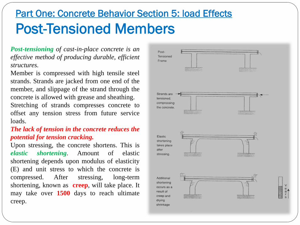
Post-tensioning of cast-in-place concrete is an
effective method of producing durable, efficient
structures.
Member is compressed with high tensile steel
strands. Strands are jacked from one end of the
member, and slippage of the strand through the
concrete is allowed with grease and sheathing.
Stretching of strands compresses concrete to
offset any tension stress from future service
loads.
The lack of tension in the concrete reduces the
potential for tension cracking.
Upon stressing, the concrete shortens. This is
elastic shortening. Amount of elastic
shortening depends upon modulus of elasticity
(E) and unit stress to which the concrete is
compressed. After stressing, long-term
shortening, known as creep, will take place. It
may take over 1500 days to reach ultimate
creep.

Restrained Volume Change

Restrained Volume Change
A common problem in post-tensioned structures is lack of design consideration of volume changes in members caused by elastic and plastic (creep) shortening.
Short columns in parking structures with opposing post-tensioned framing are ideal locations for stress relief.
The column designed for vertical loads is subject to horizontal pulling in opposite directions causing severe shear cracking.
The shear is also aggravated by diurnal solar heating if the structure is directly exposed to the sun.
Working Example
Length of beam = 18.3 m
E = (2.8 x 10⁴ MPa)
Compression = 6.9 MPa
Elastic shortening = 4.6 mm = stress/E x L
Creep shortening = 9.2 mm = 4.6 mm x 2.0 (Creep Coefficient)
Creep + Elastic = (9.2 mm) + (4.6 mm)

Part One: Concrete Behavior Section 5: Load Effects
Cylindrical Structures
Buried Pipe They are loaded with surrounding
backfill and overburden.
Non-uniform loads surrounding the
pipe may result in deformation of
the pipe.
Loads on top may exceed the load
on the pipe's underside.
The pipe is compressed in the
vertical axis and bulges along the
horizontal axis.
Cracks may develop, forming
hinges at three possible locations:
the crown (top of pipe), and at
the two spring line locations (side
of pipe).

Part One: Concrete Behavior Section 5: Load Effects
Cylindrical Structures
Tanks They are constructed to hold liquids and flowable
solids.
The loads imposed on the tank are proportional to the
material's density and height of liquid in the tank.
Pressure is greatest at the bottom and zero at the top
surface.
Internal pressure pushes against the tank wall, creating
tension.
The tension forces must be carried by the reinforcing
steel that circles the tank.
The amount of stress in the reinforcing steel dictates
how well the steel holds the concrete together, thereby
preventing cracking.

Part One: Concrete Behavior Section 5: Load Effects
Connections
Contact Loading In every structure, individual components come into
contact.
Precast structures are comprised of many
components, each interacting with others.
Point loading of contact points is quite common,
often resulting in excessive tension and shear.
Extremities and edges of members subject to point
loading are free to crack and spall when tension
stresses exceed the tensile capacity of the concrete.
Embedded reinforcing steel is not a factor, since most
steel is embedded below the contact point. Precast
double-T stems resting on ledger beams often point
load the front edge of the non-reinforced portion of
the ledger beam. Point loading can be a result of
rotation (diurnal solar heating) or length change from
seasonal thermal changes.

Contact Loading
Slabs cast on grade are separated by
construction joints.
Shear transfer between slabs at these joints are
locations where point loading can occur.
Rolling loads place the joint edges into contact
with one another, often creating stresses that
spall and crack the non-reinforced portions.
Another common problem with pavement slabs
is the filling of the open joint with non-
compressible debris, preventing the joint from
undergoing free thermal expansion.
Restrained volume change can induce very
high shear, compression and tension stresses.
Part One: Concrete Behavior Section 5: Load Effects
Connections

Part One: Concrete Behavior Section 6: Faulty Workmanship- Designer,
Detailer, Contractor
Section 6:
Faulty Workmanship-
Designer,
Detailer,
Contractor

Section 6:
Faulty Workmanship-Designer, Detailer, Contractor
The following topics are covered in this section:
Improper Reinforcing Steel Placement
Improper Post-Tensioned Cable Drape
Improper Reinforcing Steel Placement: Highly Congested Reinforcement
Improper Bar Placements Location of Stirrups
Premature Removal of Forms
Improper Column Form Placement
Cold Joints
Segregation
Improper Grades of Slab Surfaces
Construction Tolerances
Plastic Settlement (Subsidence) Cracking
Plastic Shrinkage Cracking
Honeycomb-Rock Pockets

Faulty Workmanship: Introduction Methods used to construct concrete
structures are different from methods used
in other types of construction.
Concrete is one of the few materials in
which raw ingredients are brought together
at, or near, the construction site, where they
are mixed, placed and molded into a final
product.
There are so many variables affecting the
production of concrete that there is always
a potential for something to go wrong.
Every building process includes a sequence
of necessary step-by-step operations-from
conceptual plan to finished structure.
Following is a flow chart of a typical
building process. Each box represents a
category of problems that can arise in the
building process.

Part One: Concrete Behavior Section 6: Faulty Workmanship- Designer,
Detailer, Contractor
Improper Reinforcing Steel Placement
There are two important reasons to control the
proper location of reinforcing steel in structures.
First, reinforcing steel is placed in concrete to
carry tensile loads, and if the steel is misplaced,
the concrete may not be able to carry the tensile
loads. Cantilevered slabs and negative moment
areas near columns pose particular risk.
Second, reinforcing steel requires adequate
concrete cover to protect it from corrosion.
The alkalinity of the concrete is a natural
corrosive inhibitor. If the concrete cover is
inadequate, it will not provide the necessary
long-term protection. Shifted reinforcing bar
cages in walls or beams may also cause the
reinforcing steel to lose proper cover.

ACI-required concrete cover for corrosion protection
Condition
Cover required
(mm)
Concrete deposited on the ground 76
Formed surfaces exposed to weather
bars>19 mm 51
bars<16 mm 38
Formed surfaces not exposed to weather
beams, girders, columns 38
slabs,walls,joists
bars<36 mm 19
Bars 43 mm, 57 mm 38
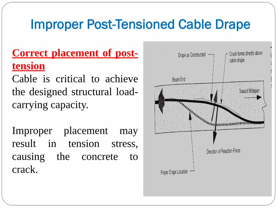
Improper Post-Tensioned Cable Drape
Correct placement of post-
tension
Cable is critical to achieve
the designed structural load-
carrying capacity.
Improper placement may
result in tension stress,
causing the concrete to
crack.

Improper Reinforcing Steel Placement
Highly Congested
Reinforcement
Beams and columns are usually heavily
reinforced members.
Lap splices require overlaps of bars
and may result in a mat of steel that
concrete mix cannot pass through
during placement and consolidation.
The result is either a visible, or
worse, a latent void around the
reinforcement.

Part One: Concrete Behavior Section 6: Faulty Workmanship- Designer,
Detailer, Contractor
Improper Bar Placement
Location of Stirrups Double-T members are a
common element used in this
type of construction.
T's are generally supported by
an inverted T-beam or ledger
beam.
The Cantilevered portion of the
beam supports the double-T's
stem.
Critical forces in the cantilever
are taken up by stirrups directly
beneath the stem location.
Improper placement of the
stirrups may result in a
failure of the ledger beam
support, and the double-T
may then drop.
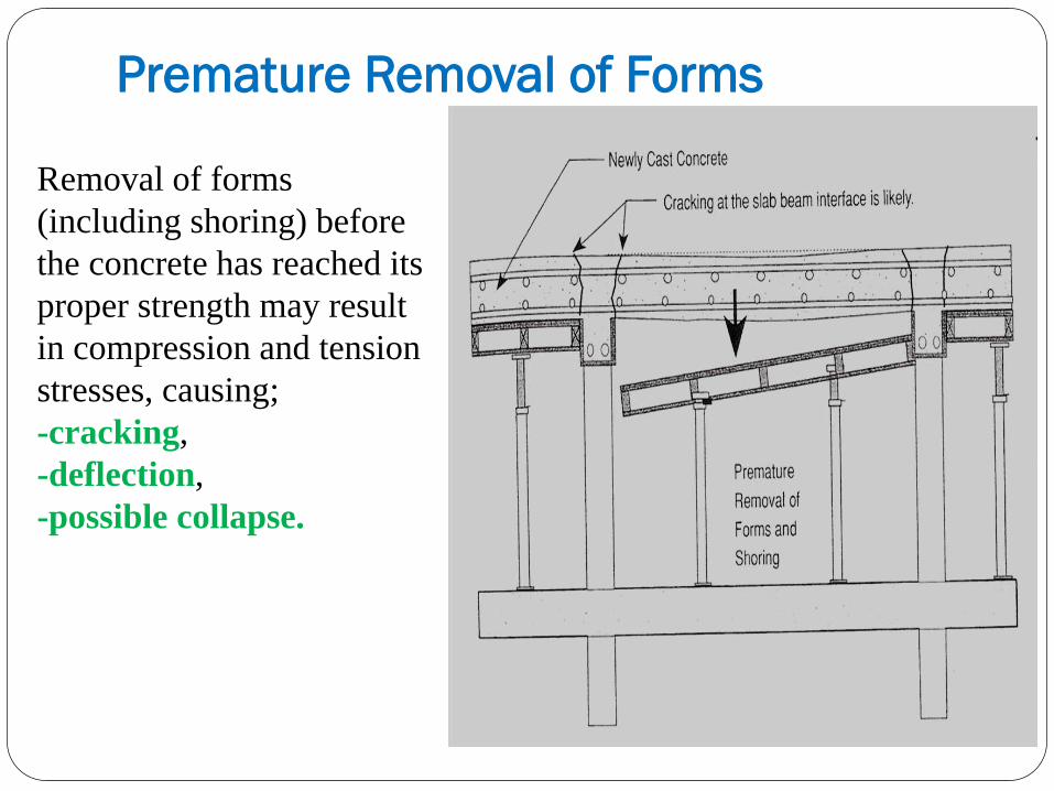
Premature Removal of Forms
Removal of forms
(including shoring) before
the concrete has reached its
proper strength may result
in compression and tension
stresses, causing;
-cracking,
-deflection,
-possible collapse.

Improper Column Form Placement
Cardboard cylinder forms are widely
used in the construction of round
columns.
Typically, columns are cast prior to
the placement of the slab/beam
formwork.
The exact elevation of the slab/beam
bottom may not be precisely
determined when the columns are
cast.
If the column is cast too tall and
penetrates the slab/beam concrete,
critical shear stresses may occur
because of inadequate shear capacity
area between the column and the
slab/beam.
The smooth form surface may not
provide adequate shear transfer.

Part One: Concrete Behavior Section 6: Faulty Workmanship- Designer,
Detailer, Contractor
Cold Joints
Cold joints are places of discontinuity within a member
where concrete may not tightly bond to itself.
Cold joints may form between planned placements and
within a placement.
Some construction placement procedures require
multiple lifts. Example: dam and tall walls.
To achieve proper bond and water-tightness, the surface
of hardened concrete must be free of dirt, debris, and
laitance.
Proper cleaning and placement procedures sometimes
are not followed or are very difficult to achieve. The
result is a weak connection between placements that
could result in weakness or leakage at a later date.
The other type of cold joint may occur within a
planned placement if a part of the concrete in one
placement sets, and then the rest of the concrete is
placed on it. During the set, laitances form, providing
for a weakened plane. Leakage may occur when the
structure is put into service.
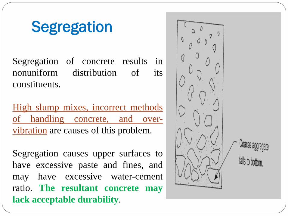
Segregation
Segregation of concrete results in
nonuniform distribution of its
constituents.
High slump mixes, incorrect methods
of handling concrete, and over-
vibration are causes of this problem.
Segregation causes upper surfaces to
have excessive paste and fines, and
may have excessive water-cement
ratio. The resultant concrete may
lack acceptable durability.

Improper Grades of Slab Surfaces
Slabs requiring drainage for proper
runoff need special attention.
Drains should be at low, not high
points.
Standing water provides concrete
with the potential for saturation, the
worst condition for a freeze-thaw
cycle.
The quicker the water runs off the
structure, the less leakage can occur
through joints and cracks.

Construction Tolerances
Structural members that are cast out of tolerance pose aesthetic and structural problems.
Members cast out of tolerance may have improper concrete cover and cross section,
which may produce eccentric loading.
TOLERANCES FOR FORMED SURFACES
Variation from plumb mm
Any 3 m length 6
Maximum entire length 25
Variations from level
Salb soffits 3 m length 6
Maximum entire length 19
Variations in cross section
minus 6
plus 13

Part One: Concrete Behavior Section 6: Faulty Workmanship- Designer,
Detailer, Contractor
Plastic Settlement
(Subsidence) Cracking
Plastic settlement cracking is
caused by the settlement of plastic
concrete around fixed
reinforcement, leaving a plastic
tear above the bar and a possible
void beneath the bar.
The probability of cracking is a
function of:
1. Cover
2. Slump
3. Bar size

Settlement of plastic concrete is caused by:
1. Low sand content and high water content
2. Large bars
3. Poor thermal insulation
4. Restraining settlement due to irregular shape
5. Excessive, uneven absorbency
6. Low humidity
7. Insufficient time between top-out of columns and placement
of slab and beam
8. Insufficient vibration
9. Movement of formwork

Probability of Subsidence (%)
Cover
(mm)
50 mm Slump 76 mm Slump 100 mm Slump
Φ13 Φ 16 Φ 19 Φ 13 Φ 16 Φ 19 Φ 13 Φ 16 Φ 19
20 80.4 87.8 92.5 91.9 98.7 100 100 100 100
25 60 71 78.1 73 83.4 89.9 85.2 94.7 100
38 18.6 34.5 45.6 31.1 47.7 58.9 44.2 61.1 72
50 0 1.8 14.1 4.9 12.7 26.3 5.1 24.7 39

Plastic Shrinkage Cracking
Plastic shrinkage is caused by
the rapid evaporation of mix
water (not bleed water) while
the concrete is in its plastic
state and in the early stages of
initial set.
Shrinkage results in cracking
when it produces tension stress
greater than the stress capacity
of the newly placed concrete.
Plastic shrinkage cracks may
lead to points of thermal and
dry shrinkage movement,
intensifying the cracking.
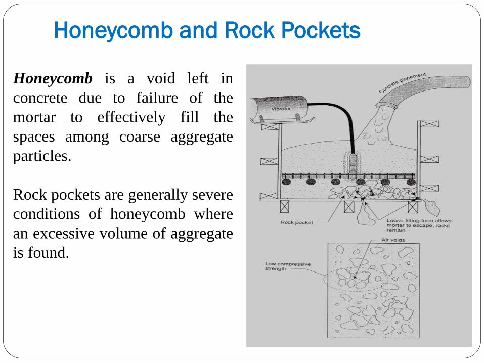
Honeycomb and Rock Pockets
Honeycomb is a void left in
concrete due to failure of the
mortar to effectively fill the
spaces among coarse aggregate
particles.
Rock pockets are generally severe
conditions of honeycomb where
an excessive volume of aggregate
is found.

Primary Causes of Honeycomb
Design of members
highly congested reinforcement
narrow section
internal interference
reinforcement splices (see figure on next page)
Forms
leaking at joints
severe grout loss


Primary Causes of Honeycomb Construction conditions
reinforcement too close to forms
high temperature
accessibility
Properties of fresh concrete
insufficient fines
low workability
early stiffening
excessive mixing
aggregate that is too large

Primary Causes of Honeycomb Placement excessive free-fall
excessive travel in forms
lift that is too high
improper tremie or drop chute
segregation
Consolidation vibrator too small
frequency too low
amplitude too small
short immersion time
excessive spacing between insertion
inadequate penetration