part systems modeling, clustering, and virtualization 1
TRANSCRIPT

PART
1Systems Modeling, Clustering,and Virtualization
The first three chapters cover systems models and review two enabling technologies. We modeldistributed systems and cloud platforms in Chapter 1. The clustering technology is presented inChapter 2, and virtualization technology in Chapter 3. These two technologies enable distributedand cloud computing. The system models include computer clusters, computing grid, P2P networks,and cloud computing platform. System clustering is supported by hardware, software, and middle-ware advances. Virtualization creates virtual machines, virtualized clusters, automation of datacen-ters, and building of elastic cloud platforms.
CHAPTER 1: DISTRIBUTED SYSTEM MODELS ANDENABLING TECHNOLOGIESThis introductory chapter assesses the evolutional changes in computing and IT trends in the past30 years. We study both high-performance computing (HPC) for scientific computing and high-throughput computing (HTC) systems for business computing. We examine clusters/MPP, grids,P2P networks, and Internet clouds. These systems are distinguished by their platform architectures,OS platforms, processing algorithms, communication protocols, security demands, and service modelsapplied. The study emphasizes the scalability, performance, availability, security, energy-efficiency,workload outsourcing, data center protection, and so on.This chapter is authored by Kai Hwang with partial contributions by Geoffrey Fox (Section 1.4.1)
and Albert Zomaya (Section 1.5.4), and assisted by Nikzad Babaii Rizvandi, Young-Choon Lee,Xiaosong Lou, and Lizhong Chen. The final manuscript was edited by Jack Dongarra.
CHAPTER 2: COMPUTER CLUSTERS FOR SCALABLEPARALLEL COMPUTINGClustering enables the construction of scalable parallel and distributed systems for both HPC andHTC applications. Today’s cluster nodes are built with either physical servers or virtual machines.In this chapter, we study clustered computing systems and massively parallel processors. We focuson design principles and assess the hardware, software, and middleware support needed. We studyscalability, availability, programmability, single system image, job management, and fault tolerance.We study the clustering MPP architectures in three top supercomputers reported in recent years,namely China’s Tiahe-1A, the Cray XT5 Jaguar, and IBM’s RoadRunner.
1

This chapter is coauthored by Kai Hwang and Jack Dongarra with partial contributions byRajkumar Buyya and Ninghui Sun. Special technical assistances are from Zhiwei Xu, Zhou Zhao,Xiaosong Lou, and Lizhong Chen.
CHAPTER 3: VIRTUAL MACHINES AND VIRTUALIZATION OF CLUSTERSAND DATA CENTERSVirtualization technology was primarily designed for the sharing of expensive hardware resourcesby multiplexing virtual machines (VM) on the same set of hardware hosts. The surge of interest ininstalling virtual machines has widened the scope of system applications and upgraded computerperformance and efficiency in recent years. We study VMs, live migration of VMs, virtual clusterconstruction, resource provisioning, virtual configuration adaptation, and the design of virtualizeddata centers for cloud computing applications. We emphasize the roles of using virtual clusters andvirtualized resource management for building dynamic grids and cloud platforms.This chapter is coauthored by Zhibin Yu and Kai Hwang with technical assistance from Hai Jin,
Xiaofei Liao, Chongyuan Qin, Lizhong Chen, and Zhou Zhao.
2 PART 1 Systems Modeling, Clustering, and Virtualization

CHAPTER
1Distributed System Models andEnabling Technologies
CHAPTER OUTLINE
Summary . . . . . . . . . . . . . . . . . . . . . . . . . . . . . . . . . . . . . . . . . . . . . . . . . . . . . . . . . . . . . . . . . . . . . . . . . . . . . . . . . . . . . . . . . . . . . 41.1 Scalable Computing over the Internet . . . . . . . . . . . . . . . . . . . . . . . . . . . . . . . . . . . . . . . . . . . . . . . . . . . . . . . . . . . . . . 4
1.1.1 The Age of Internet Computing. . . . . . . . . . . . . . . . . . . . . . . . . . . . . . . . . . . . . . . . . . . . . . . . . . . . . . . . 41.1.2 Scalable Computing Trends and New Paradigms. . . . . . . . . . . . . . . . . . . . . . . . . . . . . . . . . . . . . . . . 81.1.3 The Internet of Things and Cyber-Physical Systems. . . . . . . . . . . . . . . . . . . . . . . . . . . . . . . . . . . . 11
1.2 Technologies for Network-based Systems. . . . . . . . . . . . . . . . . . . . . . . . . . . . . . . . . . . . . . . . . . . . . . . . . . . . . . . . . 131.2.1 Multicore CPUs and Multithreading Technologies . . . . . . . . . . . . . . . . . . . . . . . . . . . . . . . . . . . . . . 141.2.2 GPU Computing to Exascale and Beyond. . . . . . . . . . . . . . . . . . . . . . . . . . . . . . . . . . . . . . . . . . . . . 171.2.3 Memory, Storage, and Wide-Area Networking. . . . . . . . . . . . . . . . . . . . . . . . . . . . . . . . . . . . . . . . . . 201.2.4 Virtual Machines and Virtualization Middleware. . . . . . . . . . . . . . . . . . . . . . . . . . . . . . . . . . . . . . . . 221.2.5 Data Center Virtualization for Cloud Computing. . . . . . . . . . . . . . . . . . . . . . . . . . . . . . . . . . . . . . . . 25
1.3 System Models for Distributed and Cloud Computing. . . . . . . . . . . . . . . . . . . . . . . . . . . . . . . . . . . . . . . . . . . . . . . 271.3.1 Clusters of Cooperative Computers . . . . . . . . . . . . . . . . . . . . . . . . . . . . . . . . . . . . . . . . . . . . . . . . . . . . 281.3.2 Grid Computing Infrastructures . . . . . . . . . . . . . . . . . . . . . . . . . . . . . . . . . . . . . . . . . . . . . . . . . . . . . . . 291.3.3 Peer-to-Peer Network Families . . . . . . . . . . . . . . . . . . . . . . . . . . . . . . . . . . . . . . . . . . . . . . . . . . . . . . . 321.3.4 Cloud Computing over the Internet . . . . . . . . . . . . . . . . . . . . . . . . . . . . . . . . . . . . . . . . . . . . . . . . . . . 34
1.4 Software Environments for Distributed Systems and Clouds. . . . . . . . . . . . . . . . . . . . . . . . . . . . . . . . . . . . . . . . . 361.4.1 Service-Oriented Architecture (SOA) . . . . . . . . . . . . . . . . . . . . . . . . . . . . . . . . . . . . . . . . . . . . . . . . . . 371.4.2 Trends toward Distributed Operating Systems. . . . . . . . . . . . . . . . . . . . . . . . . . . . . . . . . . . . . . . . . 401.4.3 Parallel and Distributed Programming Models . . . . . . . . . . . . . . . . . . . . . . . . . . . . . . . . . . . . . . . . . 42
1.5 Performance, Security, and Energy Efficiency . . . . . . . . . . . . . . . . . . . . . . . . . . . . . . . . . . . . . . . . . . . . . . . . . . . . . 441.5.1 Performance Metrics and Scalability Analysis . . . . . . . . . . . . . . . . . . . . . . . . . . . . . . . . . . . . . . . . . . 451.5.2 Fault Tolerance and System Availability . . . . . . . . . . . . . . . . . . . . . . . . . . . . . . . . . . . . . . . . . . . . . . . 481.5.3 Network Threats and Data Integrity . . . . . . . . . . . . . . . . . . . . . . . . . . . . . . . . . . . . . . . . . . . . . . . . . . . 491.5.4 Energy Efficiency in Distributed Computing . . . . . . . . . . . . . . . . . . . . . . . . . . . . . . . . . . . . . . . . . . . 51
1.6 Bibliographic Notes and Homework Problems. . . . . . . . . . . . . . . . . . . . . . . . . . . . . . . . . . . . . . . . . . . . . . . . . . . . . 55Acknowledgments . . . . . . . . . . . . . . . . . . . . . . . . . . . . . . . . . . . . . . . . . . . . . . . . . . . . . . . . . . . . . . . . . . . . . . . . . . . . . . . . . . . . 56References. . . . . . . . . . . . . . . . . . . . . . . . . . . . . . . . . . . . . . . . . . . . . . . . . . . . . . . . . . . . . . . . . . . . . . . . . . . . . . . . . . . . . . . . . . 56Homework Problems. . . . . . . . . . . . . . . . . . . . . . . . . . . . . . . . . . . . . . . . . . . . . . . . . . . . . . . . . . . . . . . . . . . . . . . . . . . . . . . . . 58
Distributed and Cloud Computing© 2012 Elsevier, Inc. All rights reserved.
3

SUMMARYThis chapter presents the evolutionary changes that have occurred in parallel, distributed, and cloudcomputing over the past 30 years, driven by applications with variable workloads and large datasets. We study both high-performance and high-throughput computing systems in parallel computersappearing as computer clusters, service-oriented architecture, computational grids, peer-to-peer net-works, Internet clouds, and the Internet of Things. These systems are distinguished by their hard-ware architectures, OS platforms, processing algorithms, communication protocols, and servicemodels applied. We also introduce essential issues on the scalability, performance, availability,security, and energy efficiency in distributed systems.
1.1 SCALABLE COMPUTING OVER THE INTERNETOver the past 60 years, computing technology has undergone a series of platform and environmentchanges. In this section, we assess evolutionary changes in machine architecture, operating systemplatform, network connectivity, and application workload. Instead of using a centralized computerto solve computational problems, a parallel and distributed computing system uses multiplecomputers to solve large-scale problems over the Internet. Thus, distributed computing becomesdata-intensive and network-centric. This section identifies the applications of modern computersystems that practice parallel and distributed computing. These large-scale Internet applicationshave significantly enhanced the quality of life and information services in society today.
1.1.1 The Age of Internet ComputingBillions of people use the Internet every day. As a result, supercomputer sites and large data centersmust provide high-performance computing services to huge numbers of Internet users concurrently.Because of this high demand, the Linpack Benchmark for high-performance computing (HPC)applications is no longer optimal for measuring system performance. The emergence of computingclouds instead demands high-throughput computing (HTC) systems built with parallel and distribu-ted computing technologies [5,6,19,25]. We have to upgrade data centers using fast servers, storagesystems, and high-bandwidth networks. The purpose is to advance network-based computing andweb services with the emerging new technologies.
1.1.1.1 The Platform EvolutionComputer technology has gone through five generations of development, with each generation lastingfrom 10 to 20 years. Successive generations are overlapped in about 10 years. For instance, from1950 to 1970, a handful of mainframes, including the IBM 360 and CDC 6400, were built to satisfythe demands of large businesses and government organizations. From 1960 to 1980, lower-cost mini-computers such as the DEC PDP 11 and VAX Series became popular among small businesses and oncollege campuses.From 1970 to 1990, we saw widespread use of personal computers built with VLSI microproces-
sors. From 1980 to 2000, massive numbers of portable computers and pervasive devices appeared inboth wired and wireless applications. Since 1990, the use of both HPC and HTC systems hidden in
4 CHAPTER 1 Distributed System Models and Enabling Technologies

clusters, grids, or Internet clouds has proliferated. These systems are employed by both consumersand high-end web-scale computing and information services.The general computing trend is to leverage shared web resources and massive amounts of data
over the Internet. Figure 1.1 illustrates the evolution of HPC and HTC systems. On the HPC side,supercomputers (massively parallel processors or MPPs) are gradually replaced by clusters ofcooperative computers out of a desire to share computing resources. The cluster is often a collectionof homogeneous compute nodes that are physically connected in close range to one another. We willdiscuss clusters, MPPs, and grid systems in more detail in Chapters 2 and 7.On the HTC side, peer-to-peer (P2P) networks are formed for distributed file sharing and
content delivery applications. A P2P system is built over many client machines (a concept wewill discuss further in Chapter 5). Peer machines are globally distributed in nature. P2P, cloudcomputing, and web service platforms are more focused on HTC applications than on HPC appli-cations. Clustering and P2P technologies lead to the development of computational grids or datagrids.
1.1.1.2 High-Performance ComputingFor many years, HPC systems emphasize the raw speed performance. The speed of HPC systemshas increased from Gflops in the early 1990s to now Pflops in 2010. This improvement was drivenmainly by the demands from scientific, engineering, and manufacturing communities. For example,
Disparatenodes
File sharing
Distributedcontrol
Geographically sparse
Service-orientedarchitecture (SOA)
Web 2.0 services
Internet clouds
Internet of Things
RFID andsensors
Disparate clusters
Virtualization
Computationaland data grids
Clusters or MPPs Centralizedcontrol
Homogeneousnodes
HPC systems
P2P network
High speed
HTC systems
FIGURE 1.1
Evolutionary trend toward parallel, distributed, and cloud computing with clusters, MPPs, P2P networks, grids,clouds, web services, and the Internet of Things.
1.1 Scalable Computing over the Internet 5

the Top 500 most powerful computer systems in the world are measured by floating-point speed inLinpack benchmark results. However, the number of supercomputer users is limited to less than10% of all computer users. Today, the majority of computer users are using desktop computers orlarge servers when they conduct Internet searches and market-driven computing tasks.
1.1.1.3 High-Throughput ComputingThe development of market-oriented high-end computing systems is undergoing a strategic changefrom an HPC paradigm to an HTC paradigm. This HTC paradigm pays more attention to high-fluxcomputing. The main application for high-flux computing is in Internet searches and web servicesby millions or more users simultaneously. The performance goal thus shifts to measure highthroughput or the number of tasks completed per unit of time. HTC technology needs to not onlyimprove in terms of batch processing speed, but also address the acute problems of cost, energysavings, security, and reliability at many data and enterprise computing centers. This book willaddress both HPC and HTC systems to meet the demands of all computer users.
1.1.1.4 Three New Computing ParadigmsAs Figure 1.1 illustrates, with the introduction of SOA, Web 2.0 services become available. Advancesin virtualization make it possible to see the growth of Internet clouds as a new computing paradigm.The maturity of radio-frequency identification (RFID), Global Positioning System (GPS), and sensortechnologies has triggered the development of the Internet of Things (IoT). These new paradigmsare only briefly introduced here. We will study the details of SOA in Chapter 5; virtualization inChapter 3; cloud computing in Chapters 4, 6, and 9; and the IoT along with cyber-physical systems(CPS) in Chapter 9.When the Internet was introduced in 1969, Leonard Klienrock of UCLA declared: “As of now,
computer networks are still in their infancy, but as they grow up and become sophisticated, we willprobably see the spread of computer utilities, which like present electric and telephone utilities,will service individual homes and offices across the country.” Many people have redefined the term“computer” since that time. In 1984, John Gage of Sun Microsystems created the slogan, “The net-work is the computer.” In 2008, David Patterson of UC Berkeley said, “The data center is the compu-ter. There are dramatic differences between developing software for millions to use as a serviceversus distributing software to run on their PCs.” Recently, Rajkumar Buyya of Melbourne Universitysimply said: “The cloud is the computer.”This book covers clusters, MPPs, P2P networks, grids, clouds, web services, social networks,
and the IoT. In fact, the differences among clusters, grids, P2P systems, and clouds may blur in thefuture. Some people view clouds as grids or clusters with modest changes through virtualization.Others feel the changes could be major, since clouds are anticipated to process huge data sets gener-ated by the traditional Internet, social networks, and the future IoT. In subsequent chapters, thedistinctions and dependencies among all distributed and cloud systems models will become clearerand more transparent.
1.1.1.5 Computing Paradigm DistinctionsThe high-technology community has argued for many years about the precise definitions ofcentralized computing, parallel computing, distributed computing, and cloud computing. In general,distributed computing is the opposite of centralized computing. The field of parallel computing
6 CHAPTER 1 Distributed System Models and Enabling Technologies

overlaps with distributed computing to a great extent, and cloud computing overlaps with distributed,centralized, and parallel computing. The following list defines these terms more clearly; their architec-tural and operational differences are discussed further in subsequent chapters.
• Centralized computing This is a computing paradigm by which all computer resources arecentralized in one physical system. All resources (processors, memory, and storage) are fullyshared and tightly coupled within one integrated OS. Many data centers and supercomputers arecentralized systems, but they are used in parallel, distributed, and cloud computing applications[18,26].
• Parallel computing In parallel computing, all processors are either tightly coupled withcentralized shared memory or loosely coupled with distributed memory. Some authors refer tothis discipline as parallel processing [15,27]. Interprocessor communication is accomplishedthrough shared memory or via message passing. A computer system capable of parallelcomputing is commonly known as a parallel computer [28]. Programs running in a parallelcomputer are called parallel programs. The process of writing parallel programs is oftenreferred to as parallel programming [32].
• Distributed computing This is a field of computer science/engineering that studies distributedsystems. A distributed system [8,13,37,46] consists of multiple autonomous computers, eachhaving its own private memory, communicating through a computer network. Informationexchange in a distributed system is accomplished through message passing. A computerprogram that runs in a distributed system is known as a distributed program. The process ofwriting distributed programs is referred to as distributed programming.
• Cloud computing An Internet cloud of resources can be either a centralized or a distributedcomputing system. The cloud applies parallel or distributed computing, or both. Clouds can bebuilt with physical or virtualized resources over large data centers that are centralized ordistributed. Some authors consider cloud computing to be a form of utility computing or servicecomputing [11,19].
As an alternative to the preceding terms, some in the high-tech community prefer the term con-current computing or concurrent programming. These terms typically refer to the union of parallelcomputing and distributing computing, although biased practitioners may interpret them differently.Ubiquitous computing refers to computing with pervasive devices at any place and time using wiredor wireless communication. The Internet of Things (IoT) is a networked connection of everydayobjects including computers, sensors, humans, etc. The IoT is supported by Internet clouds toachieve ubiquitous computing with any object at any place and time. Finally, the term Internetcomputing is even broader and covers all computing paradigms over the Internet. This book coversall the aforementioned computing paradigms, placing more emphasis on distributed and cloud com-puting and their working systems, including the clusters, grids, P2P, and cloud systems.
1.1.1.6 Distributed System FamiliesSince the mid-1990s, technologies for building P2P networks and networks of clusters have beenconsolidated into many national projects designed to establish wide area computing infrastructures,known as computational grids or data grids. Recently, we have witnessed a surge in interest inexploring Internet cloud resources for data-intensive applications. Internet clouds are the result ofmoving desktop computing to service-oriented computing using server clusters and huge databases
1.1 Scalable Computing over the Internet 7

at data centers. This chapter introduces the basics of various parallel and distributed families. Gridsand clouds are disparity systems that place great emphasis on resource sharing in hardware,software, and data sets.Design theory, enabling technologies, and case studies of these massively distributed systems
are also covered in this book. Massively distributed systems are intended to exploit a high degreeof parallelism or concurrency among many machines. In October 2010, the highest performingcluster machine was built in China with 86016 CPU processor cores and 3,211,264 GPU coresin a Tianhe-1A system. The largest computational grid connects up to hundreds of server clus-ters. A typical P2P network may involve millions of client machines working simultaneously.Experimental cloud computing clusters have been built with thousands of processing nodes. Wedevote the material in Chapters 4 through 6 to cloud computing. Case studies of HTC systemswill be examined in Chapters 4 and 9, including data centers, social networks, and virtualizedcloud platformsIn the future, both HPC and HTC systems will demand multicore or many-core processors that
can handle large numbers of computing threads per core. Both HPC and HTC systems emphasizeparallelism and distributed computing. Future HPC and HTC systems must be able to satisfy thishuge demand in computing power in terms of throughput, efficiency, scalability, and reliability. Thesystem efficiency is decided by speed, programming, and energy factors (i.e., throughput per wattof energy consumed). Meeting these goals requires to yield the following design objectives:
• Efficiency measures the utilization rate of resources in an execution model by exploitingmassive parallelism in HPC. For HTC, efficiency is more closely related to job throughput, dataaccess, storage, and power efficiency.
• Dependability measures the reliability and self-management from the chip to the system andapplication levels. The purpose is to provide high-throughput service with Quality of Service(QoS) assurance, even under failure conditions.
• Adaptation in the programming model measures the ability to support billions of job requestsover massive data sets and virtualized cloud resources under various workload and servicemodels.
• Flexibility in application deployment measures the ability of distributed systems to run well inboth HPC (science and engineering) and HTC (business) applications.
1.1.2 Scalable Computing Trends and New ParadigmsSeveral predictable trends in technology are known to drive computing applications. In fact,designers and programmers want to predict the technological capabilities of future systems. Forinstance, Jim Gray’s paper, “Rules of Thumb in Data Engineering,” is an excellent example of howtechnology affects applications and vice versa. In addition, Moore’s law indicates that processorspeed doubles every 18 months. Although Moore’s law has been proven valid over the last30 years, it is difficult to say whether it will continue to be true in the future.Gilder’s law indicates that network bandwidth has doubled each year in the past. Will that trend
continue in the future? The tremendous price/performance ratio of commodity hardware was drivenby the desktop, notebook, and tablet computing markets. This has also driven the adoption and useof commodity technologies in large-scale computing. We will discuss the future of these computingtrends in more detail in subsequent chapters. For now, it’s important to understand how distributed
8 CHAPTER 1 Distributed System Models and Enabling Technologies
systems emphasize both resource distribution and concurrency or high degree of parallelism (DoP).Let’s review the degrees of parallelism before we discuss the special requirements for distributedcomputing.
1.1.2.1 Degrees of ParallelismFifty years ago, when hardware was bulky and expensive, most computers were designed in abit-serial fashion. In this scenario, bit-level parallelism (BLP) converts bit-serial processing toword-level processing gradually. Over the years, users graduated from 4-bit microprocessors to 8-,16-, 32-, and 64-bit CPUs. This led us to the next wave of improvement, known as instruction-levelparallelism (ILP), in which the processor executes multiple instructions simultaneously rather thanonly one instruction at a time. For the past 30 years, we have practiced ILP through pipelining, super-scalar computing, VLIW (very long instruction word) architectures, and multithreading. ILP requiresbranch prediction, dynamic scheduling, speculation, and compiler support to work efficiently.
Data-level parallelism (DLP) was made popular through SIMD (single instruction, multipledata) and vector machines using vector or array types of instructions. DLP requires even more hard-ware support and compiler assistance to work properly. Ever since the introduction of multicoreprocessors and chip multiprocessors (CMPs), we have been exploring task-level parallelism (TLP).A modern processor explores all of the aforementioned parallelism types. In fact, BLP, ILP, andDLP are well supported by advances in hardware and compilers. However, TLP is far from beingvery successful due to difficulty in programming and compilation of code for efficient execution onmulticore CMPs. As we move from parallel processing to distributed processing, we will see anincrease in computing granularity to job-level parallelism (JLP). It is fair to say that coarse-grainparallelism is built on top of fine-grain parallelism.
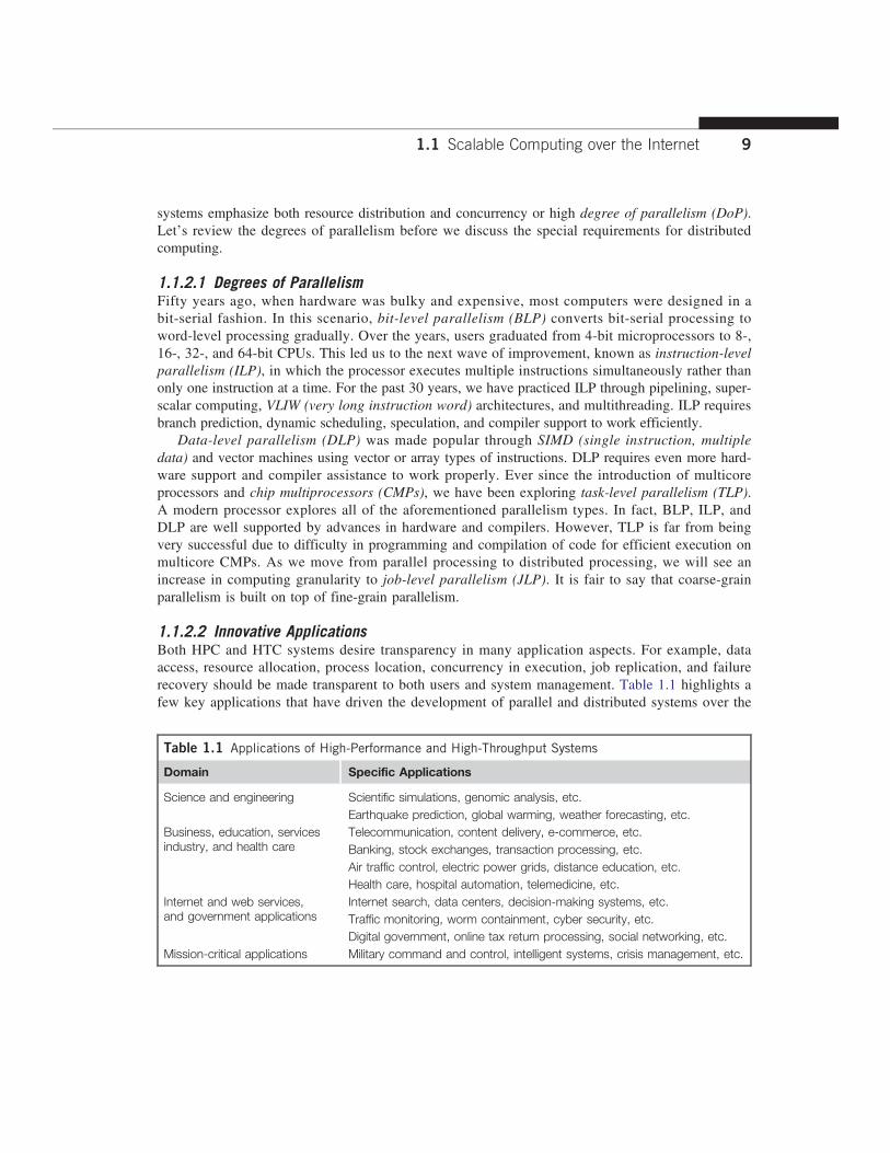
1.1.2.2 Innovative ApplicationsBoth HPC and HTC systems desire transparency in many application aspects. For example, dataaccess, resource allocation, process location, concurrency in execution, job replication, and failurerecovery should be made transparent to both users and system management. Table 1.1 highlights afew key applications that have driven the development of parallel and distributed systems over the
Table 1.1 Applications of High-Performance and High-Throughput Systems
Domain Specific Applications
Science and engineering Scientific simulations, genomic analysis, etc.Earthquake prediction, global warming, weather forecasting, etc.
Business, education, servicesindustry, and health care
Telecommunication, content delivery, e-commerce, etc.Banking, stock exchanges, transaction processing, etc.Air traffic control, electric power grids, distance education, etc.Health care, hospital automation, telemedicine, etc.
Internet and web services,and government applications
Internet search, data centers, decision-making systems, etc.Traffic monitoring, worm containment, cyber security, etc.Digital government, online tax return processing, social networking, etc.
Mission-critical applications Military command and control, intelligent systems, crisis management, etc.
1.1 Scalable Computing over the Internet 9

years. These applications spread across many important domains in science, engineering, business,education, health care, traffic control, Internet and web services, military, and governmentapplications.Almost all applications demand computing economics, web-scale data collection, system
reliability, and scalable performance. For example, distributed transaction processing is often prac-ticed in the banking and finance industry. Transactions represent 90 percent of the existing market forreliable banking systems. Users must deal with multiple database servers in distributed transactions.Maintaining the consistency of replicated transaction records is crucial in real-time banking services.Other complications include lack of software support, network saturation, and security threats in theseapplications. We will study applications and software support in more detail in subsequent chapters.
1.1.2.3 The Trend toward Utility ComputingFigure 1.2 identifies major computing paradigms to facilitate the study of distributed systems andtheir applications. These paradigms share some common characteristics. First, they are all ubiquitousin daily life. Reliability and scalability are two major design objectives in these computing models.Second, they are aimed at autonomic operations that can be self-organized to support dynamic dis-covery. Finally, these paradigms are composable with QoS and SLAs (service-level agreements).These paradigms and their attributes realize the computer utility vision.
Utility computing focuses on a business model in which customers receive computing resourcesfrom a paid service provider. All grid/cloud platforms are regarded as utility service providers.However, cloud computing offers a broader concept than utility computing. Distributed cloudapplications run on any available servers in some edge networks. Major technological challengesinclude all aspects of computer science and engineering. For example, users demand new network-efficient processors, scalable memory and storage schemes, distributed OSes, middleware formachine virtualization, new programming models, effective resource management, and application
Technologyconvergence
HTC inbusinessand HPC inscientificapplications
Computing paradigms
Attributes/capabilities
Web services
Data centers
Utility computing
Service computing
Grid computing
P2P computing
Cloud computing
Ubiquitous: Reliable and scalable
Autonomic: Dynamic and discovery
Composable: QoS, SLA, etc.
FIGURE 1.2
The vision of computer utilities in modern distributed computing systems.(Modified from presentation slide by Raj Buyya, 2010)
10 CHAPTER 1 Distributed System Models and Enabling Technologies

program development. These hardware and software supports are necessary to build distributedsystems that explore massive parallelism at all processing levels.
1.1.2.4 The Hype Cycle of New TechnologiesAny new and emerging computing and information technology may go through a hype cycle, asillustrated in Figure 1.3. This cycle shows the expectations for the technology at five differentstages. The expectations rise sharply from the trigger period to a high peak of inflated expectations.Through a short period of disillusionment, the expectation may drop to a valley and then increasesteadily over a long enlightenment period to a plateau of productivity. The number of years for anemerging technology to reach a certain stage is marked by special symbols. The hollow circlesindicate technologies that will reach mainstream adoption in two years. The gray circles representtechnologies that will reach mainstream adoption in two to five years. The solid circles representthose that require five to 10 years to reach mainstream adoption, and the triangles denote those thatrequire more than 10 years. The crossed circles represent technologies that will become obsoletebefore they reach the plateau.The hype cycle in Figure 1.3 shows the technology status as of August 2010. For example, at
that time consumer-generated media was at the disillusionment stage, and it was predicted to takeless than two years to reach its plateau of adoption. Internet micropayment systems were forecast totake two to five years to move from the enlightenment stage to maturity. It was believed that 3Dprinting would take five to 10 years to move from the rising expectation stage to mainstream adop-tion, and mesh network sensors were expected to take more than 10 years to move from the inflatedexpectation stage to a plateau of mainstream adoption.Also as shown in Figure 1.3, the cloud technology had just crossed the peak of the expectation
stage in 2010, and it was expected to take two to five more years to reach the productivity stage.However, broadband over power line technology was expected to become obsolete before leavingthe valley of disillusionment stage in 2010. Many additional technologies (denoted by dark circlesin Figure 1.3) were at their peak expectation stage in August 2010, and they were expected to takefive to 10 years to reach their plateau of success. Once a technology begins to climb the slope ofenlightenment, it may reach the productivity plateau within two to five years. Among these promis-ing technologies are the clouds, biometric authentication, interactive TV, speech recognition, predic-tive analytics, and media tablets.
1.1.3 The Internet of Things and Cyber-Physical SystemsIn this section, we will discuss two Internet development trends: the Internet of Things [48] andcyber-physical systems. These evolutionary trends emphasize the extension of the Internet to every-day objects. We will only cover the basics of these concepts here; we will discuss them in moredetail in Chapter 9.
1.1.3.1 The Internet of ThingsThe traditional Internet connects machines to machines or web pages to web pages. The concept ofthe IoT was introduced in 1999 at MIT [40]. The IoT refers to the networked interconnection ofeveryday objects, tools, devices, or computers. One can view the IoT as a wireless network of sen-sors that interconnect all things in our daily life. These things can be large or small and they vary
1.1 Scalable Computing over the Internet 11

Wire
less
pow
erM
edia
tab
let
Aug
men
ted
real
ityP
rivat
e cl
oud
com
putin
gIn
tern
et T
VS
peec
h-to
-spe
ech
tran
slat
ion
3D p
rintin
g
Soc
ial a
naly
tics
Mob
ile r
obot
s
Vid
eo s
earc
hA
uton
omou
s ve
hicl
es
Ext
rem
e tr
ansa
ctio
n pr
oces
sing
Tan
gibl
e us
er in
terf
aces
Ter
aher
tz w
aves
Com
pute
r-br
ain
inte
rfac
eC
onte
xt d
eliv
ery
arch
itect
ure
Hum
an a
ugm
enta
tion
Technolo
gy
trig
ger
Years
to m
ain
str
eam
adoption:
Expecta
tions
Peak o
f
inflate
d
expecta
tions
Tro
ugh o
f
dis
illu
sio
nm
ent Tim
e
Slo
pe o
f enlighte
nm
ent
Pla
teau o
f
pro
ductivity
Virt
ual a
ssis
tant
s
Pub
lic v
irtua
l wor
lds
Con
sum
er-g
ener
ated
med
iaId
ea m
anag
emen
t
As
of a
ugus
t 20
10
Mob
ile a
pplic
atio
n st
ores
Bio
met
ric a
uthe
ntic
atio
n m
etho
dsIn
tern
et m
icro
paym
ent sy
stem
sIn
tera
ctiv
e T
VP
redi
ctiv
e an
alyt
ics
Spe
ech
reco
gniti
on
Pen
-cen
tric
tab
let P
Cs
Ele
ctro
nic
pape
r
3D fla
t-pa
nel T
Vs
and
disp
lays
4G s
tand
ard
Act
ivity
str
eam
sC
loud
com
putin
gC
loud
/web
pla
tform
s
Ges
ture
rec
ogni
tion
Mes
h ne
twor
ks: se
nsor
Mic
robl
oggi
ng
E-B
ook
read
ers
Vid
eo tel
epre
senc
eLo
catio
n-aw
are
appl
icat
ions
Less t
han 2
years
2 t
o 5
years
5 t
o 1
0 y
ears
More
than 1
0 y
ears
Obsole
te b
efo
re
pla
teau
Bro
adba
nd o
ver
pow
er li
nes
FIGU
RE1.3
HypecycleforEm
erging
Tech
nologies,20
10.
HypeCycle
Disclaimer
TheHypeCycle
iscopyrig
hted
2010
byGartner,Inc.
andits
affiliatesan
disreused
with
perm
ission
.HypeCyclesaregrap
hicalrep
resentations
oftherelativematurity
of
tech
nologies,IT
metho
dologies
andman
agem
entdisciplines.Th
eyareintend
edsolelyas
aresearch
tool,an
dno
tas
aspecificgu
ideto
action.
Gartner
disclaim
sallw
arranties,
expressor
implied,
with
respectto
thisresearch
,includ
ingan
ywarrantiesof
merch
antabilityor
fitne
ssforapa
rticular
purpose.
ThisHypeCycle
grap
hicwas
publishe
dby
Gartner,Inc.
aspa
rtof
alarger
research
note
andshou
ldbe
evalua
tedin
thecontextof
theen
tirerepo
rt.Th
eGartner
repo
rtis
availableat
http://www.gartner.com
/it/pag
e.jsp?id=14
4761
3.
(Sou
rce:
Gartner
PressRelease
“Gartner’s
2010
HypeCy
cleSp
ecialR
eportEv
alua
tesMaturity
of1,80
0Te
chno
logies”7Octob
er20
10.)
12

with respect to time and place. The idea is to tag every object using RFID or a related sensor orelectronic technology such as GPS.With the introduction of the IPv6 protocol, 2128 IP addresses are available to distinguish all the
objects on Earth, including all computers and pervasive devices. The IoT researchers have estimatedthat every human being will be surrounded by 1,000 to 5,000 objects. The IoT needs to be designedto track 100 trillion static or moving objects simultaneously. The IoT demands universal addressa-bility of all of the objects or things. To reduce the complexity of identification, search, and storage,one can set the threshold to filter out fine-grain objects. The IoT obviously extends the Internet andis more heavily developed in Asia and European countries.In the IoT era, all objects and devices are instrumented, interconnected, and interacted with each
other intelligently. This communication can be made between people and things or among the thingsthemselves. Three communication patterns co-exist: namely H2H (human-to-human), H2T (human-to-thing), and T2T (thing-to-thing). Here things include machines such as PCs and mobile phones. The ideahere is to connect things (including human and machine objects) at any time and any place intelligentlywith low cost. Any place connections include at the PC, indoor (away from PC), outdoors, and on themove. Any time connections include daytime, night, outdoors and indoors, and on the move as well.The dynamic connections will grow exponentially into a new dynamic network of networks,
called the Internet of Things (IoT). The IoT is still in its infancy stage of development. Many proto-type IoTs with restricted areas of coverage are under experimentation at the time of this writing.Cloud computing researchers expect to use the cloud and future Internet technologies to supportfast, efficient, and intelligent interactions among humans, machines, and any objects on Earth.A smart Earth should have intelligent cities, clean water, efficient power, convenient transportation,good food supplies, responsible banks, fast telecommunications, green IT, better schools, goodhealth care, abundant resources, and so on. This dream living environment may take some time toreach fruition at different parts of the world.
1.1.3.2 Cyber-Physical SystemsA cyber-physical system (CPS) is the result of interaction between computational processes and thephysical world. A CPS integrates “cyber” (heterogeneous, asynchronous) with “physical” (concur-rent and information-dense) objects. A CPS merges the “3C” technologies of computation, commu-nication, and control into an intelligent closed feedback system between the physical world and theinformation world, a concept which is actively explored in the United States. The IoT emphasizesvarious networking connections among physical objects, while the CPS emphasizes exploration ofvirtual reality (VR) applications in the physical world. We may transform how we interact with thephysical world just like the Internet transformed how we interact with the virtual world. We willstudy IoT, CPS, and their relationship to cloud computing in Chapter 9.
1.2 TECHNOLOGIES FOR NETWORK-BASED SYSTEMSWith the concept of scalable computing under our belt, it’s time to explore hardware, software, andnetwork technologies for distributed computing system design and applications. In particular, wewill focus on viable approaches to building distributed operating systems for handling massive par-allelism in a distributed environment.
1.2 Technologies for Network-based Systems 13

1.2.1 Multicore CPUs and Multithreading TechnologiesConsider the growth of component and network technologies over the past 30 years. They arecrucial to the development of HPC and HTC systems. In Figure 1.4, processor speed is measuredin millions of instructions per second (MIPS) and network bandwidth is measured in megabits persecond (Mbps) or gigabits per second (Gbps). The unit GE refers to 1 Gbps Ethernet bandwidth.
1.2.1.1 Advances in CPU ProcessorsToday, advanced CPUs or microprocessor chips assume a multicore architecture with dual, quad,six, or more processing cores. These processors exploit parallelism at ILP and TLP levels. Processorspeed growth is plotted in the upper curve in Figure 1.4 across generations of microprocessors orCMPs. We see growth from 1 MIPS for the VAX 780 in 1978 to 1,800 MIPS for the Intel Pentium4 in 2002, up to a 22,000 MIPS peak for the Sun Niagara 2 in 2008. As the figure shows, Moore’slaw has proven to be pretty accurate in this case. The clock rate for these processors increased from10 MHz for the Intel 286 to 4 GHz for the Pentium 4 in 30 years.However, the clock rate reached its limit on CMOS-based chips due to power limitations. At the
time of this writing, very few CPU chips run with a clock rate exceeding 5 GHz. In other words,clock rate will not continue to improve unless chip technology matures. This limitation is attributedprimarily to excessive heat generation with high frequency or high voltages. The ILP is highlyexploited in modern CPU processors. ILP mechanisms include multiple-issue superscalar architecture,dynamic branch prediction, and speculative execution, among others. These ILP techniques demandhardware and compiler support. In addition, DLP and TLP are highly explored in graphics processingunits (GPUs) that adopt a many-core architecture with hundreds to thousands of simple cores.
1000000
100000
10000
CP
U s
peed
(M
IPS
)
1000
100
10
1
0.1
1000000
Intel Core i7 990x
Intel Core 2 QX9770
VAX 11/780
Intel 286
Intel Pentium
Intel Pentium Pro
Intel Pentium III
Intel Pentium 4AMD athlon FX-60
10 GE
Gigabit ethernet
Fast ethernet
Motorola 68040
Motorola 68030
Motorola 68020
100000
10000N
etw
ork
band
wid
th (
Mbp
s)
1000
100
10201120082005200219991996199319901987198419811978
Processor speed
Network bandwidth
Ethernet
40/100 GE
FIGURE 1.4
Improvement in processor and network technologies over 33 years.(Courtesy of Xiaosong Lou and Lizhong Chen of University of Southern California, 2011)
14 CHAPTER 1 Distributed System Models and Enabling Technologies

Both multi-core CPU and many-core GPU processors can handle multiple instruction threads atdifferent magnitudes today. Figure 1.5 shows the architecture of a typical multicore processor.Each core is essentially a processor with its own private cache (L1 cache). Multiple cores arehoused in the same chip with an L2 cache that is shared by all cores. In the future, multiple CMPscould be built on the same CPU chip with even the L3 cache on the chip. Multicore and multi-threaded CPUs are equipped with many high-end processors, including the Intel i7, Xeon, AMDOpteron, Sun Niagara, IBM Power 6, and X cell processors. Each core could be also multithreaded.For example, the Niagara II is built with eight cores with eight threads handled by each core. Thisimplies that the maximum ILP and TLP that can be exploited in Niagara is 64 (8 × 8 = 64). In2011, the Intel Core i7 990x has reported 159,000 MIPS execution rate as shown in the upper-most square in Figure 1.4.
1.2.1.2 Multicore CPU and Many-Core GPU ArchitecturesMulticore CPUs may increase from the tens of cores to hundreds or more in the future. But theCPU has reached its limit in terms of exploiting massive DLP due to the aforementioned memorywall problem. This has triggered the development of many-core GPUs with hundreds or more thincores. Both IA-32 and IA-64 instruction set architectures are built into commercial CPUs. Now,x-86 processors have been extended to serve HPC and HTC systems in some high-end serverprocessors.Many RISC processors have been replaced with multicore x-86 processors and many-core GPUs
in the Top 500 systems. This trend indicates that x-86 upgrades will dominate in data centers andsupercomputers. The GPU also has been applied in large clusters to build supercomputers in MPPs.In the future, the processor industry is also keen to develop asymmetric or heterogeneous chip mul-tiprocessors that can house both fat CPU cores and thin GPU cores on the same chip.
1.2.1.3 Multithreading TechnologyConsider in Figure 1.6 the dispatch of five independent threads of instructions to four pipelined datapaths (functional units) in each of the following five processor categories, from left to right: a
Multicore processor
Core 1
L1 cache
Core 2 ... ...
... ...L1 cache
Core n
L1 cache
L2 cache
L3 cache/DRAM
FIGURE 1.5
Schematic of a modern multicore CPU chip using a hierarchy of caches, where L1 cache is private to eachcore, on-chip L2 cache is shared and L3 cache or DRAM Is off the chip.
1.2 Technologies for Network-based Systems 15

four-issue superscalar processor, a fine-grain multithreaded processor, a coarse-grain multi-threaded processor, a two-core CMP, and a simultaneous multithreaded (SMT) processor. Thesuperscalar processor is single-threaded with four functional units. Each of the three multithreadedprocessors is four-way multithreaded over four functional data paths. In the dual-core processor,assume two processing cores, each a single-threaded two-way superscalar processor.Instructions from different threads are distinguished by specific shading patterns for instruc-
tions from five independent threads. Typical instruction scheduling patterns are shown here. Onlyinstructions from the same thread are executed in a superscalar processor. Fine-grain multithread-ing switches the execution of instructions from different threads per cycle. Course-grain multi-threading executes many instructions from the same thread for quite a few cycles beforeswitching to another thread. The multicore CMP executes instructions from different threads com-pletely. The SMT allows simultaneous scheduling of instructions from different threads in thesame cycle.These execution patterns closely mimic an ordinary program. The blank squares correspond to
no available instructions for an instruction data path at a particular processor cycle. More blankcells imply lower scheduling efficiency. The maximum ILP or maximum TLP is difficult to achieveat each processor cycle. The point here is to demonstrate your understanding of typical instructionscheduling patterns in these five different micro-architectures in modern processors.
Thread 1
Thread 2
4-issuesuperscalarprocessor
Time(cycle)
Thread 3
Thread 4
Thread 5
Idle slot (blank)
Fine-grainmultithreaded
processor
Coarse-grainmultithreaded
processor
Dual-core(2-processor
CMP)
Simultaneousmultithreaded
(SMT) processor
FIGURE 1.6
Five micro-architectures in modern CPU processors, that exploit ILP and TLP supported by multicore andmultithreading technologies.
16 CHAPTER 1 Distributed System Models and Enabling Technologies
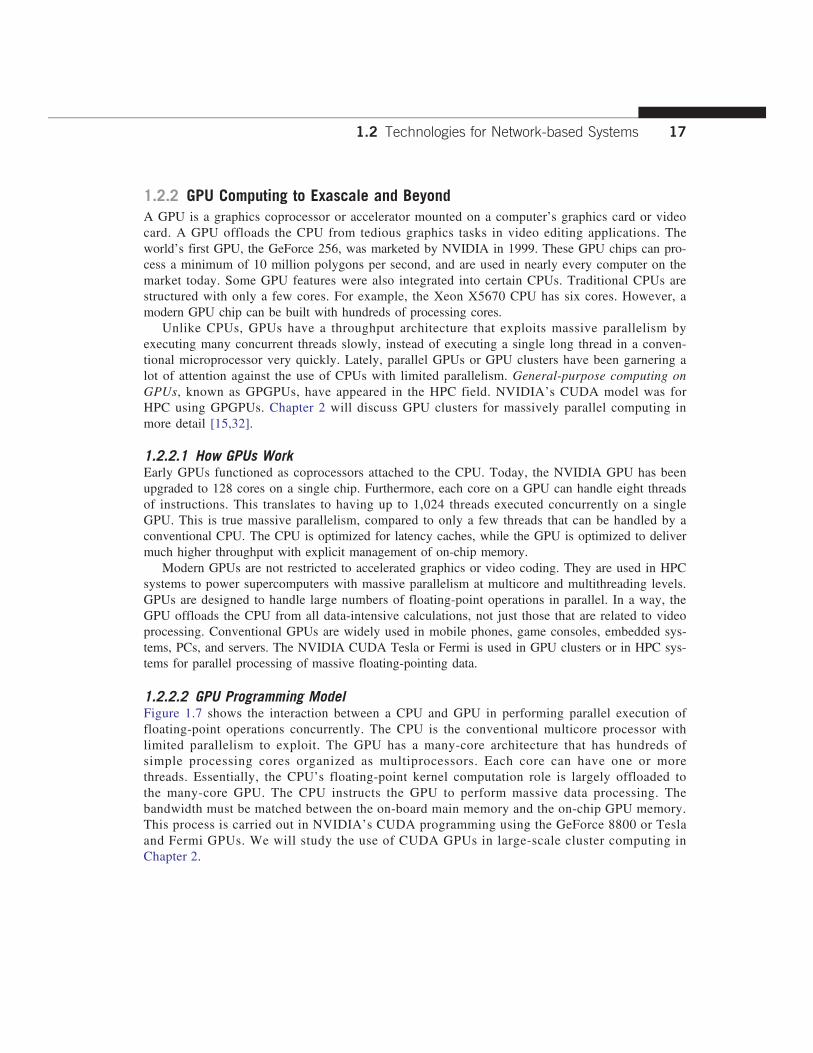
1.2.2 GPU Computing to Exascale and BeyondA GPU is a graphics coprocessor or accelerator mounted on a computer’s graphics card or videocard. A GPU offloads the CPU from tedious graphics tasks in video editing applications. Theworld’s first GPU, the GeForce 256, was marketed by NVIDIA in 1999. These GPU chips can pro-cess a minimum of 10 million polygons per second, and are used in nearly every computer on themarket today. Some GPU features were also integrated into certain CPUs. Traditional CPUs arestructured with only a few cores. For example, the Xeon X5670 CPU has six cores. However, amodern GPU chip can be built with hundreds of processing cores.Unlike CPUs, GPUs have a throughput architecture that exploits massive parallelism by
executing many concurrent threads slowly, instead of executing a single long thread in a conven-tional microprocessor very quickly. Lately, parallel GPUs or GPU clusters have been garnering alot of attention against the use of CPUs with limited parallelism. General-purpose computing onGPUs, known as GPGPUs, have appeared in the HPC field. NVIDIA’s CUDA model was forHPC using GPGPUs. Chapter 2 will discuss GPU clusters for massively parallel computing inmore detail [15,32].
1.2.2.1 How GPUs WorkEarly GPUs functioned as coprocessors attached to the CPU. Today, the NVIDIA GPU has beenupgraded to 128 cores on a single chip. Furthermore, each core on a GPU can handle eight threadsof instructions. This translates to having up to 1,024 threads executed concurrently on a singleGPU. This is true massive parallelism, compared to only a few threads that can be handled by aconventional CPU. The CPU is optimized for latency caches, while the GPU is optimized to delivermuch higher throughput with explicit management of on-chip memory.Modern GPUs are not restricted to accelerated graphics or video coding. They are used in HPC
systems to power supercomputers with massive parallelism at multicore and multithreading levels.GPUs are designed to handle large numbers of floating-point operations in parallel. In a way, theGPU offloads the CPU from all data-intensive calculations, not just those that are related to videoprocessing. Conventional GPUs are widely used in mobile phones, game consoles, embedded sys-tems, PCs, and servers. The NVIDIA CUDA Tesla or Fermi is used in GPU clusters or in HPC sys-tems for parallel processing of massive floating-pointing data.
1.2.2.2 GPU Programming ModelFigure 1.7 shows the interaction between a CPU and GPU in performing parallel execution offloating-point operations concurrently. The CPU is the conventional multicore processor withlimited parallelism to exploit. The GPU has a many-core architecture that has hundreds ofsimple processing cores organized as multiprocessors. Each core can have one or morethreads. Essentially, the CPU’s floating-point kernel computation role is largely offloaded tothe many-core GPU. The CPU instructs the GPU to perform massive data processing. Thebandwidth must be matched between the on-board main memory and the on-chip GPU memory.This process is carried out in NVIDIA’s CUDA programming using the GeForce 8800 or Teslaand Fermi GPUs. We will study the use of CUDA GPUs in large-scale cluster computing inChapter 2.
1.2 Technologies for Network-based Systems 17

Example 1.1 The NVIDIA Fermi GPU Chip with 512 CUDA Cores
In November 2010, three of the five fastest supercomputers in the world (the Tianhe-1a, Nebulae, andTsubame) used large numbers of GPU chips to accelerate floating-point computations. Figure 1.8 showsthe architecture of the Fermi GPU, a next-generation GPU from NVIDIA. This is a streaming multiprocessor(SM) module. Multiple SMs can be built on a single GPU chip. The Fermi chip has 16 SMs implementedwith 3 billion transistors. Each SM comprises up to 512 streaming processors (SPs), known as CUDAcores. The Tesla GPUs used in the Tianhe-1a have a similar architecture, with 448 CUDA cores.
The Fermi GPU is a newer generation of GPU, first appearing in 2011. The Tesla or Fermi GPU can beused in desktop workstations to accelerate floating-point calculations or for building large-scale data cen-ters. The architecture shown is based on a 2009 white paper by NVIDIA [36]. There are 32 CUDA coresper SM. Only one SM is shown in Figure 1.8. Each CUDA core has a simple pipelined integer ALU and anFPU that can be used in parallel. Each SM has 16 load/store units allowing source and destinationaddresses to be calculated for 16 threads per clock. There are four special function units (SFUs) forexecuting transcendental instructions.
All functional units and CUDA cores are interconnected by an NoC (network on chip) to a largenumber of SRAM banks (L2 caches). Each SM has a 64 KB L1 cache. The 768 KB unified L2 cache isshared by all SMs and serves all load, store, and texture operations. Memory controllers are used to con-nect to 6 GB of off-chip DRAMs. The SM schedules threads in groups of 32 parallel threads called warps.In total, 256/512 FMA (fused multiply and add) operations can be done in parallel to produce 32/64-bitfloating-point results. The 512 CUDA cores in an SM can work in parallel to deliver up to 515 Gflops ofdouble-precision results, if fully utilized. With 16 SMs, a single GPU has a peak speed of 82.4 Tflops. Only12 Fermi GPUs have the potential to reach the Pflops performance.
In the future, thousand-core GPUs may appear in Exascale (Eflops or 1018 flops) systems. Thisreflects a trend toward building future MPPs with hybrid architectures of both types of processingchips. In a DARPA report published in September 2008, four challenges are identified for exascalecomputing: (1) energy and power, (2) memory and storage, (3) concurrency and locality, and(4) system resiliency. Here, we see the progress of GPUs along with CPU advances in power
GPU
... ...
Device memoryMain
memory
CPUP1 P2 Pn
Multiprocessor N
P1 P2 Pn
Multiprocessor 1
...
FIGURE 1.7
The use of a GPU along with a CPU for massively parallel execution in hundreds or thousands of processingcores.
(Courtesy of B. He, et al., PACT’08 [23] )
18 CHAPTER 1 Distributed System Models and Enabling Technologies

efficiency, performance, and programmability [16]. In Chapter 2, we will discuss the use of GPUsto build large clusters.
1.2.2.3 Power Efficiency of the GPUBill Dally of Stanford University considers power and massive parallelism as the major benefits ofGPUs over CPUs for the future. By extrapolating current technology and computer architecture, itwas estimated that 60 Gflops/watt per core is needed to run an exaflops system (see Figure 1.10).Power constrains what we can put in a CPU or GPU chip. Dally has estimated that the CPU chipconsumes about 2 nJ/instruction, while the GPU chip requires 200 pJ/instruction, which is 1/10 lessthan that of the CPU. The CPU is optimized for latency in caches and memory, while the GPU isoptimized for throughput with explicit management of on-chip memory.Figure 1.9 compares the CPU and GPU in their performance/power ratio measured in Gflops/
watt per core. In 2010, the GPU had a value of 5 Gflops/watt at the core level, compared with less
Core Core
Core Core
Core Core
Core Core
Core Core
Core Core
Core Core
Core Core
Core Core
Core Core
Core Core
Core Core
Core Core
Core Core
Core Core
Core Core
Instruction cache
Warp scheduler
Dispatch unit
Register file (32,768 × 32-bit)
LD/ST
LD/STSFU
LD/ST
LD/ST
LD/ST
LD/ST
LD/ST
LD/ST
LD/ST
LD/ST
LD/ST
LD/ST
LD/ST
LD/ST
LD/ST
LD/ST
Interconnect network
Dispatch port
Operand collector
FP unit
Result queue
INT unit
64 KB shared memory/L1 cache
CUDA core
Uniform cache
Warp scheduler
Dispatch unit
SFU
SFU
SFU
FIGURE 1.8
NVIDIA Fermi GPU built with 16 streaming multiprocessors (SMs) of 32 CUDA cores each; only one SM Isshown. More details can be found also in [49].
(Courtesy of NVIDIA, 2009 [36] 2011)
1.2 Technologies for Network-based Systems 19
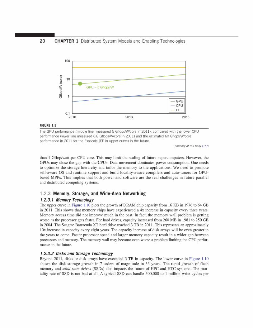
than 1 Gflop/watt per CPU core. This may limit the scaling of future supercomputers. However, theGPUs may close the gap with the CPUs. Data movement dominates power consumption. One needsto optimize the storage hierarchy and tailor the memory to the applications. We need to promoteself-aware OS and runtime support and build locality-aware compilers and auto-tuners for GPU-based MPPs. This implies that both power and software are the real challenges in future paralleland distributed computing systems.
1.2.3 Memory, Storage, and Wide-Area Networking1.2.3.1 Memory TechnologyThe upper curve in Figure 1.10 plots the growth of DRAM chip capacity from 16 KB in 1976 to 64 GBin 2011. This shows that memory chips have experienced a 4x increase in capacity every three years.Memory access time did not improve much in the past. In fact, the memory wall problem is gettingworse as the processor gets faster. For hard drives, capacity increased from 260 MB in 1981 to 250 GBin 2004. The Seagate Barracuda XT hard drive reached 3 TB in 2011. This represents an approximately10x increase in capacity every eight years. The capacity increase of disk arrays will be even greater inthe years to come. Faster processor speed and larger memory capacity result in a wider gap betweenprocessors and memory. The memory wall may become even worse a problem limiting the CPU perfor-mance in the future.
1.2.3.2 Disks and Storage TechnologyBeyond 2011, disks or disk arrays have exceeded 3 TB in capacity. The lower curve in Figure 1.10shows the disk storage growth in 7 orders of magnitude in 33 years. The rapid growth of flashmemory and solid-state drives (SSDs) also impacts the future of HPC and HTC systems. The mor-tality rate of SSD is not bad at all. A typical SSD can handle 300,000 to 1 million write cycles per
100
10
Gflops/W
(core
)
1
0.12010 2013
GPU – 5 Gflops/W
2016
GPU
CPU
EF
FIGURE 1.9
The GPU performance (middle line, measured 5 Gflops/W/core in 2011), compared with the lower CPUperformance (lower line measured 0.8 Gflops/W/core in 2011) and the estimated 60 Gflops/W/coreperformance in 2011 for the Exascale (EF in upper curve) in the future.
(Courtesy of Bill Dally [15] )
20 CHAPTER 1 Distributed System Models and Enabling Technologies

block. So the SSD can last for several years, even under conditions of heavy write usage. Flash andSSD will demonstrate impressive speedups in many applications.Eventually, power consumption, cooling, and packaging will limit large system development.
Power increases linearly with respect to clock frequency and quadratic ally with respect to voltageapplied on chips. Clock rate cannot be increased indefinitely. Lowered voltage supplies are verymuch in demand. Jim Gray once said in an invited talk at the University of Southern California,“Tape units are dead, disks are tape units, flashes are disks, and memory are caches now.” Thisclearly paints the future for disk and storage technology. In 2011, the SSDs are still too expensiveto replace stable disk arrays in the storage market.
1.2.3.3 System-Area InterconnectsThe nodes in small clusters are mostly interconnected by an Ethernet switch or a local area network(LAN). As Figure 1.11 shows, a LAN typically is used to connect client hosts to big servers.A storage area network (SAN) connects servers to network storage such as disk arrays. Networkattached storage (NAS) connects client hosts directly to the disk arrays. All three types of networksoften appear in a large cluster built with commercial network components. If no large distributedstorage is shared, a small cluster could be built with a multiport Gigabit Ethernet switch plus coppercables to link the end machines. All three types of networks are commercially available.
100000
10000
Mem
ory
chip
(M
bit)
1000
100
10
1
0.01
0.1
1000000
64KB
SeagateBarracuda XT
Hitachi GST
WDC WD1200JB
MaxtorDiamondMax 2160
Seagate ST43400N
Seagate ST-506
1MB
16MB
64MB
256MB
1GB
16GB
64GB
16
256KB
Lomega
100000
10000
Dis
k ca
paci
ty (
GB
)
100
1000
10
0.001201120082005200219991996199319901987198419811978
Memory chip
Disk capacity
0.1
1
0.01
FIGURE 1.10
Improvement in memory and disk technologies over 33 years. The Seagate Barracuda XT disk has a capacityof 3 TB in 2011.
(Courtesy of Xiaosong Lou and Lizhong Chen of University of Southern California, 2011)
1.2 Technologies for Network-based Systems 21

1.2.3.4 Wide-Area NetworkingThe lower curve in Figure 1.10 plots the rapid growth of Ethernet bandwidth from 10 Mbps in1979 to 1 Gbps in 1999, and 40 ~ 100 GE in 2011. It has been speculated that 1 Tbps networklinks will become available by 2013. According to Berman, Fox, and Hey [6], network links with1,000, 1,000, 100, 10, and 1 Gbps bandwidths were reported, respectively, for international,national, organization, optical desktop, and copper desktop connections in 2006.An increase factor of two per year on network performance was reported, which is faster than
Moore’s law on CPU speed doubling every 18 months. The implication is that more computers willbe used concurrently in the future. High-bandwidth networking increases the capability of buildingmassively distributed systems. The IDC 2010 report predicted that both InfiniBand and Ethernetwill be the two major interconnect choices in the HPC arena. Most data centers are using GigabitEthernet as the interconnect in their server clusters.
1.2.4 Virtual Machines and Virtualization MiddlewareA conventional computer has a single OS image. This offers a rigid architecture that tightly couplesapplication software to a specific hardware platform. Some software running well on one machinemay not be executable on another platform with a different instruction set under a fixed OS. Virtualmachines (VMs) offer novel solutions to underutilized resources, application inflexibility, softwaremanageability, and security concerns in existing physical machines.Today, to build large clusters, grids, and clouds, we need to access large amounts of computing,
storage, and networking resources in a virtualized manner. We need to aggregate those resources,and hopefully, offer a single system image. In particular, a cloud of provisioned resources must relyon virtualization of processors, memory, and I/O facilities dynamically. We will cover virtualizationin Chapter 3. However, the basic concepts of virtualized resources, such as VMs, virtual storage,and virtual networking and their virtualization software or middleware, need to be introduced first.Figure 1.12 illustrates the architectures of three VM configurations.
Client hosts(PC/WS)
NAS
SAN
LAN
Servers(large machines)
Network storage(disk arrays)
FIGURE 1.11
Three interconnection networks for connecting servers, client hosts, and storage devices; the LAN connectsclient hosts and servers, the SAN connects servers with disk arrays, and the NAS connects clients with largestorage systems in the network environment.
22 CHAPTER 1 Distributed System Models and Enabling Technologies

1.2.4.1 Virtual MachinesIn Figure 1.12, the host machine is equipped with the physical hardware, as shown at the bottom ofthe figure. An example is an x-86 architecture desktop running its installed Windows OS, as shownin part (a) of the figure. The VM can be provisioned for any hardware system. The VM is builtwith virtual resources managed by a guest OS to run a specific application. Between the VMs andthe host platform, one needs to deploy a middleware layer called a virtual machine monitor (VMM).Figure 1.12(b) shows a native VM installed with the use of a VMM called a hypervisor in privi-leged mode. For example, the hardware has x-86 architecture running the Windows system.The guest OS could be a Linux system and the hypervisor is the XEN system developed at
Cambridge University. This hypervisor approach is also called bare-metal VM, because the hypervi-sor handles the bare hardware (CPU, memory, and I/O) directly. Another architecture is the host VMshown in Figure 1.12(c). Here the VMM runs in nonprivileged mode. The host OS need not be modi-fied. The VM can also be implemented with a dual mode, as shown in Figure 1.12(d). Part of theVMM runs at the user level and another part runs at the supervisor level. In this case, the host OSmay have to be modified to some extent. Multiple VMs can be ported to a given hardware system tosupport the virtualization process. The VM approach offers hardware independence of the OS andapplications. The user application running on its dedicated OS could be bundled together as a virtualappliance that can be ported to any hardware platform. The VM could run on an OS different fromthat of the host computer.
1.2.4.2 VM Primitive OperationsThe VMM provides the VM abstraction to the guest OS. With full virtualization, the VMM exportsa VM abstraction identical to the physical machine so that a standard OS such as Windows 2000 orLinux can run just as it would on the physical hardware. Low-level VMM operations are indicatedby Mendel Rosenblum [41] and illustrated in Figure 1.13.
Application
Operating system(OS)
Hardware
(b) Native VM
Guest apps
Guest OS
Hardware
VMM(hypervisor)
Hardware
Host OS
(c) Hosted VM
Guest apps
VMM
(d) Dual-mode VM
HostOS
Guest apps
Guest OS
VMM
Hardware
VMM
Nonprivilegedmode in userspace
Privilegedmode insystemspace
(a) Physical machine
FIGURE 1.12
Three VM architectures in (b), (c), and (d), compared with the traditional physical machine shown in (a).(Courtesy of M. Abde-Majeed and S. Kulkarni, 2009 USC)
1.2 Technologies for Network-based Systems 23

• First, the VMs can be multiplexed between hardware machines, as shown in Figure 1.13(a).• Second, a VM can be suspended and stored in stable storage, as shown in Figure 1.13(b).• Third, a suspended VM can be resumed or provisioned to a new hardware platform, as shown inFigure 1.13(c).
• Finally, a VM can be migrated from one hardware platform to another, as shown in Figure 1.13(d).
These VM operations enable a VM to be provisioned to any available hardware platform. Theyalso enable flexibility in porting distributed application executions. Furthermore, the VM approachwill significantly enhance the utilization of server resources. Multiple server functions can beconsolidated on the same hardware platform to achieve higher system efficiency. This will eliminateserver sprawl via deployment of systems as VMs, which move transparency to the shared hardware.With this approach, VMware claimed that server utilization could be increased from its current5–15 percent to 60–80 percent.
1.2.4.3 Virtual InfrastructuresPhysical resources for compute, storage, and networking at the bottom of Figure 1.14 are mapped tothe needy applications embedded in various VMs at the top. Hardware and software are then sepa-rated. Virtual infrastructure is what connects resources to distributed applications. It is a dynamicmapping of system resources to specific applications. The result is decreased costs and increasedefficiency and responsiveness. Virtualization for server consolidation and containment is a goodexample of this. We will discuss VMs and virtualization support in Chapter 3. Virtualization supportfor clusters, clouds, and grids is covered in Chapters 3, 4, and 7, respectively.
Hardware Hardware Hardware
Hardware Hardware
Hardware
Hardware
Storage
(c) Provision (resume)
(a) Multiplexing
StorageStorage
(d) Life migration
App App
App
App App App
App
App
OS OS OS
Storage
(b) Suspension (storage)
App
OS
OS OS OS
OS OS
VMM VMM VMM
VMM
VMM VMMVMM
VMM
Hardware
FIGURE 1.13
VM multiplexing, suspension, provision, and migration in a distributed computing environment.(Courtesy of M. Rosenblum, Keynote address, ACM ASPLOS 2006 [41] )
24 CHAPTER 1 Distributed System Models and Enabling Technologies

1.2.5 Data Center Virtualization for Cloud ComputingIn this section, we discuss basic architecture and design considerations of data centers. Cloud architectureis built with commodity hardware and network devices. Almost all cloud platforms choose the popularx86 processors. Low-cost terabyte disks and Gigabit Ethernet are used to build data centers. Data centerdesign emphasizes the performance/price ratio over speed performance alone. In other words, storageand energy efficiency are more important than shear speed performance. Figure 1.13 shows the servergrowth and cost breakdown of data centers over the past 15 years. Worldwide, about 43 million serversare in use as of 2010. The cost of utilities exceeds the cost of hardware after three years.
1.2.5.1 Data Center Growth and Cost BreakdownA large data center may be built with thousands of servers. Smaller data centers are typically builtwith hundreds of servers. The cost to build and maintain data center servers has increased over theyears. According to a 2009 IDC report (see Figure 1.14), typically only 30 percent of data centercosts goes toward purchasing IT equipment (such as servers and disks), 33 percent is attributed tothe chiller, 18 percent to the uninterruptible power supply (UPS), 9 percent to computer room airconditioning (CRAC), and the remaining 7 percent to power distribution, lighting, and transformercosts. Thus, about 60 percent of the cost to run a data center is allocated to management and main-tenance. The server purchase cost did not increase much with time. The cost of electricity and cool-ing did increase from 5 percent to 14 percent in 15 years.
1.2.5.2 Low-Cost Design PhilosophyHigh-end switches or routers may be too cost-prohibitive for building data centers. Thus, usinghigh-bandwidth networks may not fit the economics of cloud computing. Given a fixed budget,
80$300
Millions installed serversCustomer spending ($B)
$250
$200
$150
$100
$50
$0’96 ’97 ’98 ’99 ’00 ’01 ’02 ’03 ’04 ’05 ’06 ’07 ’08 ’09 ’10 ’11 ’12 ’13
60
40
20
0
Server spending
Management costPower & cooling expense
Physical server installed base (Millions)Logical server installed base (Millions)
Virtualizationmanagement
gap
FIGURE 1.14
Growth and cost breakdown of data centers over the years.(Source: IDC Report, 2009)
1.2 Technologies for Network-based Systems 25

commodity switches and networks are more desirable in data centers. Similarly, using commodityx86 servers is more desired over expensive mainframes. The software layer handles network trafficbalancing, fault tolerance, and expandability. Currently, nearly all cloud computing data centers useEthernet as their fundamental network technology.
1.2.5.3 Convergence of TechnologiesEssentially, cloud computing is enabled by the convergence of technologies in four areas: (1) hard-ware virtualization and multi-core chips, (2) utility and grid computing, (3) SOA, Web 2.0, and WSmashups, and (4) atonomic computing and data center automation. Hardware virtualization and mul-ticore chips enable the existence of dynamic configurations in the cloud. Utility and grid computingtechnologies lay the necessary foundation for computing clouds. Recent advances in SOA, Web2.0, and mashups of platforms are pushing the cloud another step forward. Finally, achievements inautonomic computing and automated data center operations contribute to the rise of cloudcomputing.Jim Gray once posted the following question: “Science faces a data deluge. How to manage and
analyze information?” This implies that science and our society face the same challenge of datadeluge. Data comes from sensors, lab experiments, simulations, individual archives, and the web inall scales and formats. Preservation, movement, and access of massive data sets require generictools supporting high-performance, scalable file systems, databases, algorithms, workflows, andvisualization. With science becoming data-centric, a new paradigm of scientific discovery is becom-ing based on data-intensive technologies.On January 11, 2007, the Computer Science and Telecommunication Board (CSTB) recom-
mended fostering tools for data capture, data creation, and data analysis. A cycle of interactionexists among four technical areas. First, cloud technology is driven by a surge of interest in datadeluge. Also, cloud computing impacts e-science greatly, which explores multicore and parallelcomputing technologies. These two hot areas enable the buildup of data deluge. To support data-intensive computing, one needs to address workflows, databases, algorithms, and virtualizationissues.By linking computer science and technologies with scientists, a spectrum of e-science or
e-research applications in biology, chemistry, physics, the social sciences, and the humanities hasgenerated new insights from interdisciplinary activities. Cloud computing is a transformativeapproach as it promises much more than a data center model. It fundamentally changes how weinteract with information. The cloud provides services on demand at the infrastructure, platform, orsoftware level. At the platform level, MapReduce offers a new programming model that transpar-ently handles data parallelism with natural fault tolerance capability. We will discuss MapReduce inmore detail in Chapter 6.Iterative MapReduce extends MapReduce to support a broader range of data mining algorithms
commonly used in scientific applications. The cloud runs on an extremely large cluster of commod-ity computers. Internal to each cluster node, multithreading is practiced with a large number ofcores in many-core GPU clusters. Data-intensive science, cloud computing, and multicore comput-ing are converging and revolutionizing the next generation of computing in architectural design andprogramming challenges. They enable the pipeline: Data becomes information and knowledge, andin turn becomes machine wisdom as desired in SOA.
26 CHAPTER 1 Distributed System Models and Enabling Technologies

1.3 SYSTEM MODELS FOR DISTRIBUTED AND CLOUD COMPUTINGDistributed and cloud computing systems are built over a large number of autonomous computernodes. These node machines are interconnected by SANs, LANs, or WANs in a hierarchical man-ner. With today’s networking technology, a few LAN switches can easily connect hundreds ofmachines as a working cluster. A WAN can connect many local clusters to form a very large clusterof clusters. In this sense, one can build a massive system with millions of computers connected toedge networks.Massive systems are considered highly scalable, and can reach web-scale connectivity, either
physically or logically. In Table 1.2, massive systems are classified into four groups: clusters, P2Pnetworks, computing grids, and Internet clouds over huge data centers. In terms of node number,these four system classes may involve hundreds, thousands, or even millions of computers asparticipating nodes. These machines work collectively, cooperatively, or collaboratively at variouslevels. The table entries characterize these four system classes in various technical and applicationaspects.
Table 1.2 Classification of Parallel and Distributed Computing Systems
Functionality,Applications
ComputerClusters[10,28,38]
Peer-to-PeerNetworks[34,46]
Data/ComputationalGrids [6,18,51]
Cloud Platforms[1,9,11,12,30]
Architecture,NetworkConnectivity, andSize
Network ofcompute nodesinterconnected bySAN, LAN, orWANhierarchically
Flexible networkof client machineslogicallyconnected by anoverlay network
Heterogeneousclustersinterconnected byhigh-speednetwork links overselected resourcesites
Virtualized clusterof servers overdata centers viaSLA
Control andResourcesManagement
Homogeneousnodes withdistributedcontrol, runningUNIX or Linux
Autonomousclient nodes, freein and out, withself-organization
Centralizedcontrol, server-oriented withauthenticatedsecurity
Dynamic resourceprovisioning ofservers, storage,and networks
Applications andNetwork-centricServices
High-performancecomputing,search engines,and web services,etc.
Most appealing tobusiness filesharing, contentdelivery, andsocial networking
Distributedsupercomputing,global problemsolving, and datacenter services
Upgraded websearch, utilitycomputing, andoutsourcedcomputingservices
RepresentativeOperationalSystems
Google searchengine, SunBlade,IBM RoadRunner, CrayXT4, etc.
Gnutella, eMule,BitTorrent,Napster, KaZaA,Skype, JXTA
TeraGrid,GriPhyN, UKEGEE, D-Grid,ChinaGrid, etc.
Google AppEngine, IBMBluecloud, AWS,and MicrosoftAzure
1.3 System Models for Distributed and Cloud Computing 27

From the application perspective, clusters are most popular in supercomputing applications. In2009, 417 of the Top 500 supercomputers were built with cluster architecture. It is fair to say thatclusters have laid the necessary foundation for building large-scale grids and clouds. P2P networksappeal most to business applications. However, the content industry was reluctant to accept P2Ptechnology for lack of copyright protection in ad hoc networks. Many national grids built in thepast decade were underutilized for lack of reliable middleware or well-coded applications. Potentialadvantages of cloud computing include its low cost and simplicity for both providers and users.
1.3.1 Clusters of Cooperative ComputersA computing cluster consists of interconnected stand-alone computers which work cooperatively asa single integrated computing resource. In the past, clustered computer systems have demonstratedimpressive results in handling heavy workloads with large data sets.
1.3.1.1 Cluster ArchitectureFigure 1.15 shows the architecture of a typical server cluster built around a low-latency, high-bandwidth interconnection network. This network can be as simple as a SAN (e.g., Myrinet) or aLAN (e.g., Ethernet). To build a larger cluster with more nodes, the interconnection network can bebuilt with multiple levels of Gigabit Ethernet, Myrinet, or InfiniBand switches. Through hierarchicalconstruction using a SAN, LAN, or WAN, one can build scalable clusters with an increasingnumber of nodes. The cluster is connected to the Internet via a virtual private network (VPN)gateway. The gateway IP address locates the cluster. The system image of a computer is decided bythe way the OS manages the shared cluster resources. Most clusters have loosely coupled nodecomputers. All resources of a server node are managed by their own OS. Thus, most clusters havemultiple system images as a result of having many autonomous nodes under different OS control.
I/O devicesDisk arrays
GatewayS2
Sn–1 Sn
S1
S0
A Cluster
Servers The Internet
SAN, LAN, NAS Networks(Ethernet, Myrinet, InfiniBand, etc.)
FIGURE 1.15
A cluster of servers interconnected by a high-bandwidth SAN or LAN with shared I/O devices and disk arrays;the cluster acts as a single computer attached to the Internet.
28 CHAPTER 1 Distributed System Models and Enabling Technologies

1.3.1.2 Single-System ImageGreg Pfister [38] has indicated that an ideal cluster should merge multiple system images intoa single-system image (SSI). Cluster designers desire a cluster operating system or some middle-ware to support SSI at various levels, including the sharing of CPUs, memory, and I/O across allcluster nodes. An SSI is an illusion created by software or hardware that presents a collection ofresources as one integrated, powerful resource. SSI makes the cluster appear like a singlemachine to the user. A cluster with multiple system images is nothing but a collection of inde-pendent computers.
1.3.1.3 Hardware, Software, and Middleware SupportIn Chapter 2, we will discuss cluster design principles for both small and large clusters. Clustersexploring massive parallelism are commonly known as MPPs. Almost all HPC clusters in the Top500 list are also MPPs. The building blocks are computer nodes (PCs, workstations, servers, orSMP), special communication software such as PVM or MPI, and a network interface card in eachcomputer node. Most clusters run under the Linux OS. The computer nodes are interconnected by ahigh-bandwidth network (such as Gigabit Ethernet, Myrinet, InfiniBand, etc.).Special cluster middleware supports are needed to create SSI or high availability (HA). Both
sequential and parallel applications can run on the cluster, and special parallel environments areneeded to facilitate use of the cluster resources. For example, distributed memory has multipleimages. Users may want all distributed memory to be shared by all servers by forming distribu-ted shared memory (DSM). Many SSI features are expensive or difficult to achieve at variouscluster operational levels. Instead of achieving SSI, many clusters are loosely coupled machines.Using virtualization, one can build many virtual clusters dynamically, upon user demand. Wewill discuss virtual clusters in Chapter 3 and the use of virtual clusters for cloud computing inChapters 4, 5, 6, and 9.
1.3.1.4 Major Cluster Design IssuesUnfortunately, a cluster-wide OS for complete resource sharing is not available yet. Middlewareor OS extensions were developed at the user space to achieve SSI at selected functional levels.Without this middleware, cluster nodes cannot work together effectively to achieve cooperativecomputing. The software environments and applications must rely on the middleware to achievehigh performance. The cluster benefits come from scalable performance, efficient message passing,high system availability, seamless fault tolerance, and cluster-wide job management, as summarizedin Table 1.3. We will address these issues in Chapter 2.
1.3.2 Grid Computing InfrastructuresIn the past 30 years, users have experienced a natural growth path from Internet to web and gridcomputing services. Internet services such as the Telnet command enables a local computer to con-nect to a remote computer. A web service such as HTTP enables remote access of remote webpages. Grid computing is envisioned to allow close interaction among applications running on dis-tant computers simultaneously. Forbes Magazine has projected the global growth of the IT-basedeconomy from $1 trillion in 2001 to $20 trillion by 2015. The evolution from Internet to web andgrid services is certainly playing a major role in this growth.
1.3 System Models for Distributed and Cloud Computing 29

1.3.2.1 Computational GridsLike an electric utility power grid, a computing grid offers an infrastructure that couples computers,software/middleware, special instruments, and people and sensors together. The grid is often con-structed across LAN, WAN, or Internet backbone networks at a regional, national, or global scale.Enterprises or organizations present grids as integrated computing resources. They can also beviewed as virtual platforms to support virtual organizations. The computers used in a grid are pri-marily workstations, servers, clusters, and supercomputers. Personal computers, laptops, and PDAscan be used as access devices to a grid system.Figure 1.16 shows an example computational grid built over multiple resource sites owned by
different organizations. The resource sites offer complementary computing resources, includingworkstations, large servers, a mesh of processors, and Linux clusters to satisfy a chain of computa-tional needs. The grid is built across various IP broadband networks including LANs and WANsalready used by enterprises or organizations over the Internet. The grid is presented to users as anintegrated resource pool as shown in the upper half of the figure.Special instruments may be involved such as using the radio telescope in SETI@Home
search of life in the galaxy and the austrophysics@Swineburne for pulsars. At the server end,the grid is a network. At the client end, we see wired or wireless terminal devices. The gridintegrates the computing, communication, contents, and transactions as rented services. Enter-prises and consumers form the user base, which then defines the usage trends and service char-acteristics. Many national and international grids will be reported in Chapter 7, the NSF
Table 1.3 Critical Cluster Design Issues and Feasible Implementations
Features Functional Characterization Feasible Implementations
Availability and Support Hardware and software support forsustained HA in cluster
Failover, failback, check pointing,rollback recovery, nonstop OS, etc.
Hardware Fault Tolerance Automated failure management toeliminate all single points of failure
Component redundancy, hotswapping, RAID, multiple powersupplies, etc.
Single System Image (SSI) Achieving SSI at functional level withhardware and software support,middleware, or OS extensions
Hardware mechanisms ormiddleware support to achieve DSMat coherent cache level
Efficient Communications To reduce message-passing systemoverhead and hide latencies
Fast message passing, activemessages, enhanced MPI library, etc.
Cluster-wide JobManagement
Using a global job managementsystem with better scheduling andmonitoring
Application of single-jobmanagement systems such as LSF,Codine, etc.
Dynamic Load Balancing Balancing the workload of allprocessing nodes along with failurerecovery
Workload monitoring, processmigration, job replication and gangscheduling, etc.
Scalability andProgrammability
Adding more servers to a cluster oradding more clusters to a grid asthe workload or data set increases
Use of scalable interconnect,performance monitoring, distributedexecution environment, and bettersoftware tools
30 CHAPTER 1 Distributed System Models and Enabling Technologies

TeraGrid in US, EGEE in Europe, and ChinaGrid in China for various distributed scientific gridapplications.
1.3.2.2 Grid FamiliesGrid technology demands new distributed computing models, software/middleware support, networkprotocols, and hardware infrastructures. National grid projects are followed by industrial grid plat-form development by IBM, Microsoft, Sun, HP, Dell, Cisco, EMC, Platform Computing, andothers. New grid service providers (GSPs) and new grid applications have emerged rapidly, similarto the growth of Internet and web services in the past two decades. In Table 1.4, grid systems areclassified in essentially two categories: computational or data grids and P2P grids. Computing ordata grids are built primarily at the national level. In Chapter 7, we will cover grid applications andlessons learned.
Expensiveequipment
IP Broadband network
The Internet
Grid
Databases
FIGURE 1.16
Computational grid or data grid providing computing utility, data, and information services through resourcesharing and cooperation among participating organizations.
(Courtesy of Z. Xu, Chinese Academy of Science, 2004)
Table 1.4 Two Grid Computing Infrastructures and Representative Systems
Design IssuesComputational and DataGrids P2P Grids
Grid Applications Reported Distributed supercomputing,National Grid initiatives, etc.
Open grid with P2P flexibility, allresources from client machines
Representative Systems TeraGrid built in US, ChinaGrid inChina, and the e-Science gridbuilt in UK
JXTA, FightAid@home,SETI@home
Development Lessons Learned Restricted user groups,middleware bugs, protocols toacquire resources
Unreliable user-contributedresources, limited to a few apps
1.3 System Models for Distributed and Cloud Computing 31

1.3.3 Peer-to-Peer Network FamiliesAn example of a well-established distributed system is the client-server architecture. In this sce-nario, client machines (PCs and workstations) are connected to a central server for compute, e-mail,file access, and database applications. The P2P architecture offers a distributed model of networkedsystems. First, a P2P network is client-oriented instead of server-oriented. In this section, P2P sys-tems are introduced at the physical level and overlay networks at the logical level.
1.3.3.1 P2P SystemsIn a P2P system, every node acts as both a client and a server, providing part of the systemresources. Peer machines are simply client computers connected to the Internet. All client machinesact autonomously to join or leave the system freely. This implies that no master-slave relationshipexists among the peers. No central coordination or central database is needed. In other words, nopeer machine has a global view of the entire P2P system. The system is self-organizing with distrib-uted control.Figure 1.17 shows the architecture of a P2P network at two abstraction levels. Initially, the peers
are totally unrelated. Each peer machine joins or leaves the P2P network voluntarily. Only the parti-cipating peers form the physical network at any time. Unlike the cluster or grid, a P2P network doesnot use a dedicated interconnection network. The physical network is simply an ad hoc networkformed at various Internet domains randomly using the TCP/IP and NAI protocols. Thus, the physi-cal network varies in size and topology dynamically due to the free membership in the P2Pnetwork.
1.3.3.2 Overlay NetworksData items or files are distributed in the participating peers. Based on communication or file-sharingneeds, the peer IDs form an overlay network at the logical level. This overlay is a virtual network
Overlay network
Virtuallink
Physicallink
AP
IP network
FIGURE 1.17
The structure of a P2P system by mapping a physical IP network to an overlay network built with virtuallinks.
(Courtesy of Zhenyu Li, Institute of Computing Technology, Chinese Academy of Sciences, 2010)
32 CHAPTER 1 Distributed System Models and Enabling Technologies

formed by mapping each physical machine with its ID, logically, through a virtual mapping asshown in Figure 1.17. When a new peer joins the system, its peer ID is added as a node in theoverlay network. When an existing peer leaves the system, its peer ID is removed from the overlaynetwork automatically. Therefore, it is the P2P overlay network that characterizes the logical con-nectivity among the peers.There are two types of overlay networks: unstructured and structured. An unstructured overlay
network is characterized by a random graph. There is no fixed route to send messages or filesamong the nodes. Often, flooding is applied to send a query to all nodes in an unstructured overlay,thus resulting in heavy network traffic and nondeterministic search results. Structured overlay net-works follow certain connectivity topology and rules for inserting and removing nodes (peer IDs)from the overlay graph. Routing mechanisms are developed to take advantage of the structuredoverlays.
1.3.3.3 P2P Application FamiliesBased on application, P2P networks are classified into four groups, as shown in Table 1.5. The firstfamily is for distributed file sharing of digital contents (music, videos, etc.) on the P2P network. Thisincludes many popular P2P networks such as Gnutella, Napster, and BitTorrent, among others. Colla-boration P2P networks include MSN or Skype chatting, instant messaging, and collaborative design,among others. The third family is for distributed P2P computing in specific applications. For example,SETI@home provides 25 Tflops of distributed computing power, collectively, over 3 million Internethost machines. Other P2P platforms, such as JXTA, .NET, and FightingAID@home, support naming,discovery, communication, security, and resource aggregation in some P2P applications. We will dis-cuss these topics in more detail in Chapters 8 and 9.
1.3.3.4 P2P Computing ChallengesP2P computing faces three types of heterogeneity problems in hardware, software, and networkrequirements. There are too many hardware models and architectures to select from; incompat-ibility exists between software and the OS; and different network connections and protocols
Table 1.5 Major Categories of P2P Network Families [46]
SystemFeatures
Distributed FileSharing
CollaborativePlatform
Distributed P2PComputing P2P Platform
AttractiveApplications
Contentdistribution of MP3music, video, opensoftware, etc.
Instant messaging,collaborativedesign and gaming
Scientificexploration andsocial networking
Open networks forpublic resources
OperationalProblems
Loose security andserious onlinecopyright violations
Lack of trust,disturbed byspam, privacy, andpeer collusion
Security holes,selfish partners,and peer collusion
Lack of standardsor protectionprotocols
ExampleSystems
Gnutella, Napster,eMule, BitTorrent,Aimster, KaZaA,etc.
ICQ, AIM, Groove,Magi, MultiplayerGames, Skype,etc.
SETI@home,Geonome@home,etc.
JXTA, .NET,FightingAid@home,etc.
1.3 System Models for Distributed and Cloud Computing 33

make it too complex to apply in real applications. We need system scalability as the workloadincreases. System scaling is directly related to performance and bandwidth. P2P networks dohave these properties. Data location is also important to affect collective performance. Datalocality, network proximity, and interoperability are three design objectives in distributed P2Papplications.P2P performance is affected by routing efficiency and self-organization by participating peers.
Fault tolerance, failure management, and load balancing are other important issues in using overlaynetworks. Lack of trust among peers poses another problem. Peers are strangers to one another.Security, privacy, and copyright violations are major worries by those in the industry in terms ofapplying P2P technology in business applications [35]. In a P2P network, all clients provide resourcesincluding computing power, storage space, and I/O bandwidth. The distributed nature of P2P net-works also increases robustness, because limited peer failures do not form a single point of failure.By replicating data in multiple peers, one can easily lose data in failed nodes. On the other hand,
disadvantages of P2P networks do exist. Because the system is not centralized, managing it is difficult.In addition, the system lacks security. Anyone can log on to the system and cause damage or abuse.Further, all client computers connected to a P2P network cannot be considered reliable or virus-free. Insummary, P2P networks are reliable for a small number of peer nodes. They are only useful for applica-tions that require a low level of security and have no concern for data sensitivity. We will discuss P2Pnetworks in Chapter 8, and extending P2P technology to social networking in Chapter 9.
1.3.4 Cloud Computing over the InternetGordon Bell, Jim Gray, and Alex Szalay [5] have advocated: “Computational science is changing tobe data-intensive. Supercomputers must be balanced systems, not just CPU farms but also petascaleI/O and networking arrays.” In the future, working with large data sets will typically mean sendingthe computations (programs) to the data, rather than copying the data to the workstations. Thisreflects the trend in IT of moving computing and data from desktops to large data centers, wherethere is on-demand provision of software, hardware, and data as a service. This data explosion haspromoted the idea of cloud computing.Cloud computing has been defined differently by many users and designers. For example, IBM, a
major player in cloud computing, has defined it as follows: “A cloud is a pool of virtualized computerresources. A cloud can host a variety of different workloads, including batch-style backend jobs andinteractive and user-facing applications.” Based on this definition, a cloud allows workloads to bedeployed and scaled out quickly through rapid provisioning of virtual or physical machines. The cloudsupports redundant, self-recovering, highly scalable programming models that allow workloads torecover from many unavoidable hardware/software failures. Finally, the cloud system should be able tomonitor resource use in real time to enable rebalancing of allocations when needed.
1.3.4.1 Internet CloudsCloud computing applies a virtualized platform with elastic resources on demand by provisioninghardware, software, and data sets dynamically (see Figure 1.18). The idea is to move desktopcomputing to a service-oriented platform using server clusters and huge databases at data centers.Cloud computing leverages its low cost and simplicity to benefit both users and providers. Machinevirtualization has enabled such cost-effectiveness. Cloud computing intends to satisfy many user
34 CHAPTER 1 Distributed System Models and Enabling Technologies

applications simultaneously. The cloud ecosystem must be designed to be secure, trustworthy, anddependable. Some computer users think of the cloud as a centralized resource pool. Others considerthe cloud to be a server cluster which practices distributed computing over all the servers used.
1.3.4.2 The Cloud LandscapeTraditionally, a distributed computing system tends to be owned and operated by an autonomousadministrative domain (e.g., a research laboratory or company) for on-premises computing needs.However, these traditional systems have encountered several performance bottlenecks: constant sys-tem maintenance, poor utilization, and increasing costs associated with hardware/software upgrades.Cloud computing as an on-demand computing paradigm resolves or relieves us from these problems.Figure 1.19 depicts the cloud landscape and major cloud players, based on three cloud service mod-els. Chapters 4, 6, and 9 provide details regarding these cloud service offerings. Chapter 3 covers therelevant virtualization tools.
• Infrastructure as a Service (IaaS) This model puts together infrastructures demanded byusers—namely servers, storage, networks, and the data center fabric. The user can deploy andrun on multiple VMs running guest OSes on specific applications. The user does not manage orcontrol the underlying cloud infrastructure, but can specify when to request and release theneeded resources.
• Platform as a Service (PaaS) This model enables the user to deploy user-built applicationsonto a virtualized cloud platform. PaaS includes middleware, databases, development tools, andsome runtime support such as Web 2.0 and Java. The platform includes both hardware andsoftware integrated with specific programming interfaces. The provider supplies the API andsoftware tools (e.g., Java, Python, Web 2.0, .NET). The user is freed from managing the cloudinfrastructure.
• Software as a Service (SaaS) This refers to browser-initiated application software overthousands of paid cloud customers. The SaaS model applies to business processes, industryapplications, consumer relationship management (CRM), enterprise resources planning (ERP),human resources (HR), and collaborative applications. On the customer side, there is no upfrontinvestment in servers or software licensing. On the provider side, costs are rather low, comparedwith conventional hosting of user applications.
Storage
Submit requests
Paid services
User
Service
Internetcloud Network
SoftwareHardware
FIGURE 1.18
Virtualized resources from data centers to form an Internet cloud, provisioned with hardware, software,storage, network, and services for paid users to run their applications.
1.3 System Models for Distributed and Cloud Computing 35

Internet clouds offer four deployment modes: private, public, managed, and hybrid [11]. Thesemodes demand different levels of security implications. The different SLAs imply that the securityresponsibility is shared among all the cloud providers, the cloud resource consumers, and the third-party cloud-enabled software providers. Advantages of cloud computing have been advocated bymany IT experts, industry leaders, and computer science researchers.In Chapter 4, we will describe major cloud platforms that have been built and various cloud
services offerings. The following list highlights eight reasons to adapt the cloud for upgradedInternet applications and web services:
1. Desired location in areas with protected space and higher energy efficiency2. Sharing of peak-load capacity among a large pool of users, improving overall utilization3. Separation of infrastructure maintenance duties from domain-specific application development4. Significant reduction in cloud computing cost, compared with traditional computing paradigms5. Cloud computing programming and application development6. Service and data discovery and content/service distribution7. Privacy, security, copyright, and reliability issues8. Service agreements, business models, and pricing policies
1.4 SOFTWARE ENVIRONMENTS FOR DISTRIBUTED SYSTEMSAND CLOUDS
This section introduces popular software environments for using distributed and cloud computingsystems. Chapters 5 and 6 discuss this subject in more depth.
PaaS: Provide a
programming
environment to
build and manage
the deployment
of a cloud
application
IaaS: Provide a data
center and a way to
host client VMs and
data
SaaS: Delivery of
software from the
cloud to the desktop
FIGURE 1.19
Three cloud service models in a cloud landscape of major providers.(Courtesy of Dennis Gannon, keynote address at Cloudcom2010 [19] )
36 CHAPTER 1 Distributed System Models and Enabling Technologies

1.4.1 Service-Oriented Architecture (SOA)In grids/web services, Java, and CORBA, an entity is, respectively, a service, a Java object, and aCORBA distributed object in a variety of languages. These architectures build on the traditionalseven Open Systems Interconnection (OSI) layers that provide the base networking abstractions. Ontop of this we have a base software environment, which would be .NET or Apache Axis for webservices, the Java Virtual Machine for Java, and a broker network for CORBA. On top of this baseenvironment one would build a higher level environment reflecting the special features of thedistributed computing environment. This starts with entity interfaces and inter-entity communication,which rebuild the top four OSI layers but at the entity and not the bit level. Figure 1.20 shows thelayered architecture for distributed entities used in web services and grid systems.
1.4.1.1 Layered Architecture for Web Services and GridsThe entity interfaces correspond to the Web Services Description Language (WSDL), Java method, andCORBA interface definition language (IDL) specifications in these example distributed systems. Theseinterfaces are linked with customized, high-level communication systems: SOAP, RMI, and IIOP in thethree examples. These communication systems support features including particular message patterns(such as Remote Procedure Call or RPC), fault recovery, and specialized routing. Often, these commu-nication systems are built on message-oriented middleware (enterprise bus) infrastructure such as Web-Sphere MQ or Java Message Service (JMS) which provide rich functionality and support virtualizationof routing, senders, and recipients.In the case of fault tolerance, the features in the Web Services Reliable Messaging (WSRM)
framework mimic the OSI layer capability (as in TCP fault tolerance) modified to match the differ-ent abstractions (such as messages versus packets, virtualized addressing) at the entity levels. Secur-ity is a critical capability that either uses or reimplements the capabilities seen in concepts such asInternet Protocol Security (IPsec) and secure sockets in the OSI layers. Entity communication issupported by higher level services for registries, metadata, and management of the entities discussedin Section 5.4.
Application specific services/gridsGenerally useful services and grids
WorkflowService management
Service discovery and informationService Internet transport Protocol
Service interfaces
Base hosting environmentProtocol HTTP FTP DNS ...
Presentation XDR ...Session SSH ...
Transport TCP UDP ...Network IP ...
Data link/Physical
Bit levelInternet
Higherlevelservices
Servicecontext
ServiceInternet
FIGURE 1.20
Layered achitecture for web services and the grids.
1.4 Software Environments for Distributed Systems and Clouds 37

Here, one might get several models with, for example, JNDI (Jini and Java Naming and DirectoryInterface) illustrating different approaches within the Java distributed object model. The CORBA Trad-ing Service, UDDI (Universal Description, Discovery, and Integration), LDAP (Lightweight DirectoryAccess Protocol), and ebXML (Electronic Business using eXtensible Markup Language) are otherexamples of discovery and information services described in Section 5.4. Management services includeservice state and lifetime support; examples include the CORBA Life Cycle and Persistent states, thedifferent Enterprise JavaBeans models, Jini’s lifetime model, and a suite of web services specificationsin Chapter 5. The above language or interface terms form a collection of entity-level capabilities.The latter can have performance advantages and offers a “shared memory” model allowing more
convenient exchange of information. However, the distributed model has two critical advantages:namely, higher performance (from multiple CPUs when communication is unimportant) and acleaner separation of software functions with clear software reuse and maintenance advantages. Thedistributed model is expected to gain popularity as the default approach to software systems. In theearlier years, CORBA and Java approaches were used in distributed systems rather than today’sSOAP, XML, or REST (Representational State Transfer).
1.4.1.2 Web Services and ToolsLoose coupling and support of heterogeneous implementations make services more attractive thandistributed objects. Figure 1.20 corresponds to two choices of service architecture: web servicesor REST systems (these are further discussed in Chapter 5). Both web services and REST sys-tems have very distinct approaches to building reliable interoperable systems. In web services,one aims to fully specify all aspects of the service and its environment. This specification is car-ried with communicated messages using Simple Object Access Protocol (SOAP). The hostingenvironment then becomes a universal distributed operating system with fully distributed capabil-ity carried by SOAP messages. This approach has mixed success as it has been hard to agree onkey parts of the protocol and even harder to efficiently implement the protocol by software suchas Apache Axis.In the REST approach, one adopts simplicity as the universal principle and delegates most of
the difficult problems to application (implementation-specific) software. In a web services language,REST has minimal information in the header, and the message body (that is opaque to genericmessage processing) carries all the needed information. REST architectures are clearly more appro-priate for rapid technology environments. However, the ideas in web services are important andprobably will be required in mature systems at a different level in the stack (as part of the applica-tion). Note that REST can use XML schemas but not those that are part of SOAP; “XML overHTTP” is a popular design choice in this regard. Above the communication and managementlayers, we have the ability to compose new entities or distributed programs by integrating severalentities together.In CORBA and Java, the distributed entities are linked with RPCs, and the simplest way to build
composite applications is to view the entities as objects and use the traditional ways of linking themtogether. For Java, this could be as simple as writing a Java program with method calls replaced byRemote Method Invocation (RMI), while CORBA supports a similar model with a syntax reflecting theC++ style of its entity (object) interfaces. Allowing the term “grid” to refer to a single service or torepresent a collection of services, here sensors represent entities that output data (as messages), andgrids and clouds represent collections of services that have multiple message-based inputs and outputs.
38 CHAPTER 1 Distributed System Models and Enabling Technologies

1.4.1.3 The Evolution of SOAAs shown in Figure 1.21, service-oriented architecture (SOA) has evolved over the years. SOAapplies to building grids, clouds, grids of clouds, clouds of grids, clouds of clouds (also known asinterclouds), and systems of systems in general. A large number of sensors provide data-collectionservices, denoted in the figure as SS (sensor service). A sensor can be a ZigBee device, a Bluetoothdevice, a WiFi access point, a personal computer, a GPA, or a wireless phone, among other things.Raw data is collected by sensor services. All the SS devices interact with large or small computers,many forms of grids, databases, the compute cloud, the storage cloud, the filter cloud, the discoverycloud, and so on. Filter services ( fs in the figure) are used to eliminate unwanted raw data, in orderto respond to specific requests from the web, the grid, or web services.A collection of filter services forms a filter cloud. We will cover various clouds for compute,
storage, filter, and discovery in Chapters 4, 5, and 6, and various grids, P2P networks, and the IoTin Chapters 7, 8, and 9. SOA aims to search for, or sort out, the useful data from the massive
SS
SS
SS
SS
SS S
SSS
SS
SS
SS S
S
SS
SS
SS
SS
SS
SS
SS
SS
SS
fs
SS
SS
SS
Anothergrid
Anothergrid
Anothergrid
Database
Computecloud
Storagecloud
Sensor or datainterchange
service
Traditional gridwith exposedservices
Portal
Inter-service messages
Filtercloud
Filtercloud
Filtercloud
Filtercloud
Filtercloud Filter
cloud
Discoverycloud
Discoverycloud
Anotherservice
fs
fs fs
fs
fs
Filterservice
fs
fs
fs
fs
fs
fs
Filterservice
fs
fs
fs
fs
fs
fs
Filterservice
fs
fs
fs
fs
fs
fs
Filterservice
Raw data Data Information Knowledge Wisdom Decisions
FIGURE 1.21
The evolution of SOA: grids of clouds and grids, where “SS” refers to a sensor service and “fs” to a filter ortransforming service.
1.4 Software Environments for Distributed Systems and Clouds 39

amounts of raw data items. Processing this data will generate useful information, and subsequently,the knowledge for our daily use. In fact, wisdom or intelligence is sorted out of large knowledgebases. Finally, we make intelligent decisions based on both biological and machine wisdom. Read-ers will see these structures more clearly in subsequent chapters.Most distributed systems require a web interface or portal. For raw data collected by a large
number of sensors to be transformed into useful information or knowledge, the data stream may gothrough a sequence of compute, storage, filter, and discovery clouds. Finally, the inter-service mes-sages converge at the portal, which is accessed by all users. Two example portals, OGFCE andHUBzero, are described in Section 5.3 using both web service (portlet) and Web 2.0 (gadget) tech-nologies. Many distributed programming models are also built on top of these basic constructs.
1.4.1.4 Grids versus CloudsThe boundary between grids and clouds are getting blurred in recent years. For web services, work-flow technologies are used to coordinate or orchestrate services with certain specifications used todefine critical business process models such as two-phase transactions. Section 5.2 discusses the gen-eral approach used in workflow, the BPEL Web Service standard, and several important workflowapproaches including Pegasus, Taverna, Kepler, Trident, and Swift. In all approaches, one is buildinga collection of services which together tackle all or part of a distributed computing problem.In general, a grid system applies static resources, while a cloud emphasizes elastic resources. For
some researchers, the differences between grids and clouds are limited only in dynamic resourceallocation based on virtualization and autonomic computing. One can build a grid out of multipleclouds. This type of grid can do a better job than a pure cloud, because it can explicitly supportnegotiated resource allocation. Thus one may end up building with a system of systems: such as acloud of clouds, a grid of clouds, or a cloud of grids, or inter-clouds as a basic SOA architecture.
1.4.2 Trends toward Distributed Operating SystemsThe computers in most distributed systems are loosely coupled. Thus, a distributed system inher-ently has multiple system images. This is mainly due to the fact that all node machines run with anindependent operating system. To promote resource sharing and fast communication among nodemachines, it is best to have a distributed OS that manages all resources coherently and efficiently.Such a system is most likely to be a closed system, and it will likely rely on message passing andRPCs for internode communications. It should be pointed out that a distributed OS is crucial forupgrading the performance, efficiency, and flexibility of distributed applications.
1.4.2.1 Distributed Operating SystemsTanenbaum [26] identifies three approaches for distributing resource management functions in adistributed computer system. The first approach is to build a network OS over a large number ofheterogeneous OS platforms. Such an OS offers the lowest transparency to users, and is essentiallya distributed file system, with independent computers relying on file sharing as a means ofcommunication. The second approach is to develop middleware to offer a limited degree of resourcesharing, similar to the MOSIX/OS developed for clustered systems (see Section 2.4.4). The thirdapproach is to develop a truly distributed OS to achieve higher use or system transparency.Table 1.6 compares the functionalities of these three distributed operating systems.
40 CHAPTER 1 Distributed System Models and Enabling Technologies

1.4.2.2 Amoeba versus DCEDCE is a middleware-based system for distributed computing environments. The Amoeba wasacademically developed at Free University in the Netherlands. The Open Software Foundation(OSF) has pushed the use of DCE for distributed computing. However, the Amoeba, DCE, andMOSIX2 are still research prototypes that are primarily used in academia. No successful commer-cial OS products followed these research systems.We need new web-based operating systems to support virtualization of resources in distributed
environments. This is still a wide-open area of research. To balance the resource management work-load, the functionalities of such a distributed OS should be distributed to any available server. Inthis sense, the conventional OS runs only on a centralized platform. With the distribution of OSservices, the distributed OS design should take a lightweight microkernel approach like the Amoeba[46], or should extend an existing OS like the DCE [7] by extending UNIX. The trend is to freeusers from most resource management duties.
1.4.2.3 MOSIX2 for Linux ClustersMOSIX2 is a distributed OS [3], which runs with a virtualization layer in the Linux environment.This layer provides a partial single-system image to user applications. MOSIX2 supports bothsequential and parallel applications, and discovers resources and migrates software processes amongLinux nodes. MOSIX2 can manage a Linux cluster or a grid of multiple clusters. Flexible management
Table 1.6 Feature Comparison of Three Distributed Operating Systems
Distributed OSFunctionality
AMOEBA Developedat Vrije University [46]
DCE as OSF/1 byOpen SoftwareFoundation [7]
MOSIX for LinuxClusters at HebrewUniversity [3]
History and CurrentSystem Status
Written in C and testedin the Europeancommunity; version 5.2released in 1995
Built as a userextension on top ofUNIX, VMS, Windows,OS/2, etc.
Developed since 1977,now called MOSIX2used in HPC Linux andGPU clusters
Distributed OSArchitecture
Microkernel-based andlocation-transparent,uses many servers tohandle files, directory,replication, run, boot,and TCP/IP services
Middleware OSproviding a platform forrunning distributedapplications; Thesystem supports RPC,security, and threads
A distributed OS withresource discovery,process migration,runtime support, loadbalancing, flood control,configuration, etc.
OS Kernel, Middleware,and VirtualizationSupport
A special microkernelthat handles low-levelprocess, memory, I/O,and communicationfunctions
DCE packages handlefile,time, directory,security services, RPC,and authentication atmiddleware or userspace
MOSIX2 runs withLinux 2.6; extensionsfor use in multipleclusters and cloudswith provisioned VMs
CommunicationMechanisms
Uses a network-layerFLIP protocol and RPCto implement point-to-point and groupcommunication
RPC supportsauthenticatedcommunication andother security servicesin user programs
Using PVM, MPI incollectivecommunications,priority process control,and queuing services
1.4 Software Environments for Distributed Systems and Clouds 41
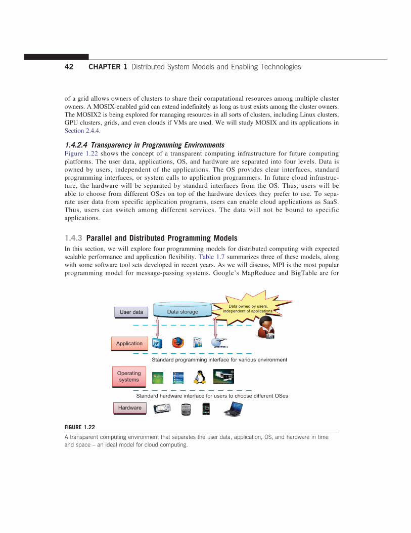
of a grid allows owners of clusters to share their computational resources among multiple clusterowners. A MOSIX-enabled grid can extend indefinitely as long as trust exists among the cluster owners.The MOSIX2 is being explored for managing resources in all sorts of clusters, including Linux clusters,GPU clusters, grids, and even clouds if VMs are used. We will study MOSIX and its applications inSection 2.4.4.
1.4.2.4 Transparency in Programming EnvironmentsFigure 1.22 shows the concept of a transparent computing infrastructure for future computingplatforms. The user data, applications, OS, and hardware are separated into four levels. Data isowned by users, independent of the applications. The OS provides clear interfaces, standardprogramming interfaces, or system calls to application programmers. In future cloud infrastruc-ture, the hardware will be separated by standard interfaces from the OS. Thus, users will beable to choose from different OSes on top of the hardware devices they prefer to use. To sepa-rate user data from specific application programs, users can enable cloud applications as SaaS.Thus, users can switch among different services. The data will not be bound to specificapplications.
1.4.3 Parallel and Distributed Programming ModelsIn this section, we will explore four programming models for distributed computing with expectedscalable performance and application flexibility. Table 1.7 summarizes three of these models, alongwith some software tool sets developed in recent years. As we will discuss, MPI is the most popularprogramming model for message-passing systems. Google’s MapReduce and BigTable are for
User data Data storage
Standard programming interface for various environment
Standard hardware interface for users to choose different OSes
Data owned by users,independent of applications.
Application
Operatingsystems
Hardware
FIGURE 1.22
A transparent computing environment that separates the user data, application, OS, and hardware in timeand space – an ideal model for cloud computing.
42 CHAPTER 1 Distributed System Models and Enabling Technologies

effective use of resources from Internet clouds and data centers. Service clouds demand extendingHadoop, EC2, and S3 to facilitate distributed computing over distributed storage systems. Manyother models have also been proposed or developed in the past. In Chapters 5 and 6, we will dis-cuss parallel and distributed programming in more details.
1.4.3.1 Message-Passing Interface (MPI)This is the primary programming standard used to develop parallel and concurrent programs to runon a distributed system. MPI is essentially a library of subprograms that can be called from C orFORTRAN to write parallel programs running on a distributed system. The idea is to embodyclusters, grid systems, and P2P systems with upgraded web services and utility computing applica-tions. Besides MPI, distributed programming can be also supported with low-level primitives suchas the Parallel Virtual Machine (PVM). Both MPI and PVM are described in Hwang and Xu [28].
1.4.3.2 MapReduceThis is a web programming model for scalable data processing on large clusters over large data sets[16]. The model is applied mainly in web-scale search and cloud computing applications. The userspecifies a Map function to generate a set of intermediate key/value pairs. Then the user applies aReduce function to merge all intermediate values with the same intermediate key. MapReduce ishighly scalable to explore high degrees of parallelism at different job levels. A typical MapReducecomputation process can handle terabytes of data on tens of thousands or more client machines.Hundreds of MapReduce programs can be executed simultaneously; in fact, thousands of MapRe-duce jobs are executed on Google’s clusters every day.
1.4.3.3 Hadoop LibraryHadoop offers a software platform that was originally developed by a Yahoo! group. The pack-age enables users to write and run applications over vast amounts of distributed data. Users caneasily scale Hadoop to store and process petabytes of data in the web space. Also, Hadoop iseconomical in that it comes with an open source version of MapReduce that minimizes overhead
Table 1.7 Parallel and Distributed Programming Models and Tool Sets
Model Description Features
MPI A library of subprograms that can becalled from C or FORTRAN to writeparallel programs running on distributedcomputer systems [6,28,42]
Specify synchronous or asynchronouspoint-to-point and collectivecommunication commands and I/Ooperations in user programs formessage-passing execution
MapReduce A web programming model for scalabledata processing on large clusters overlarge data sets, or in web searchoperations [16]
Map function generates a set ofintermediate key/value pairs; Reducefunction merges all intermediate valueswith the same key
Hadoop A software library to write and run largeuser applications on vast data sets inbusiness applications (http://hadoop.apache.org/core)
A scalable, economical, efficient, andreliable tool for providing users witheasy access of commercial clusters
1.4 Software Environments for Distributed Systems and Clouds 43

in task spawning and massive data communication. It is efficient, as it processes data with a highdegree of parallelism across a large number of commodity nodes, and it is reliable in that it auto-matically keeps multiple data copies to facilitate redeployment of computing tasks upon unex-pected system failures.
1.4.3.4 Open Grid Services Architecture (OGSA)The development of grid infrastructure is driven by large-scale distributed computing applications.These applications must count on a high degree of resource and data sharing. Table 1.8 introducesOGSA as a common standard for general public use of grid services. Genesis II is a realization ofOGSA. Key features include a distributed execution environment, Public Key Infrastructure (PKI)services using a local certificate authority (CA), trust management, and security policies in gridcomputing.
1.4.3.5 Globus Toolkits and ExtensionsGlobus is a middleware library jointly developed by the U.S. Argonne National Laboratory andUSC Information Science Institute over the past decade. This library implements some of theOGSA standards for resource discovery, allocation, and security enforcement in a grid environment.The Globus packages support multisite mutual authentication with PKI certificates. The current ver-sion of Globus, GT 4, has been in use since 2008. In addition, IBM has extended Globus for busi-ness applications. We will cover Globus and other grid computing middleware in more detail inChapter 7.
1.5 PERFORMANCE, SECURITY, AND ENERGY EFFICIENCYIn this section, we will discuss the fundamental design principles along with rules of thumb forbuilding massively distributed computing systems. Coverage includes scalability, availability, pro-gramming models, and security issues in clusters, grids, P2P networks, and Internet clouds.
Table 1.8 Grid Standards and Toolkits for Scientific and Engineering Applications [6]
Standards Service FunctionalitiesKey Features and SecurityInfrastructure
OGSA Standard Open Grid Services Architecture; offerscommon grid service standards forgeneral public use
Supports a heterogeneous distributedenvironment, bridging CAs, multipletrusted intermediaries, dynamic policies,multiple security mechanisms, etc.
Globus Toolkits Resource allocation, Globus securityinfrastructure (GSI), and genericsecurity service API
Sign-in multisite authentication withPKI, Kerberos, SSL, Proxy, delegation,and GSS API for message integrity andconfidentiality
IBM Grid Toolbox AIX and Linux grids built on top ofGlobus Toolkit, autonomic computing,replica services
Uses simple CA, grants access, gridservice (ReGS), supports gridapplication for Java (GAF4J), GridMapin IntraGrid for security update
44 CHAPTER 1 Distributed System Models and Enabling Technologies

1.5.1 Performance Metrics and Scalability AnalysisPerformance metrics are needed to measure various distributed systems. In this section, we will dis-cuss various dimensions of scalability and performance laws. Then we will examine system scalabil-ity against OS images and the limiting factors encountered.
1.5.1.1 Performance MetricsWe discussed CPU speed in MIPS and network bandwidth in Mbps in Section 1.3.1 to estimate pro-cessor and network performance. In a distributed system, performance is attributed to a large numberof factors. System throughput is often measured in MIPS, Tflops (tera floating-point operations persecond), or TPS (transactions per second). Other measures include job response time and networklatency. An interconnection network that has low latency and high bandwidth is preferred. Systemoverhead is often attributed to OS boot time, compile time, I/O data rate, and the runtime support sys-tem used. Other performance-related metrics include the QoS for Internet and web services; systemavailability and dependability; and security resilience for system defense against network attacks.
1.5.1.2 Dimensions of ScalabilityUsers want to have a distributed system that can achieve scalable performance. Any resource upgrade ina system should be backward compatible with existing hardware and software resources. Overdesignmay not be cost-effective. System scaling can increase or decrease resources depending on many practi-cal factors. The following dimensions of scalability are characterized in parallel and distributed systems:
• Size scalability This refers to achieving higher performance or more functionality by increasingthe machine size. The word “size” refers to adding processors, cache, memory, storage, or I/Ochannels. The most obvious way to determine size scalability is to simply count the number ofprocessors installed. Not all parallel computer or distributed architectures are equally size-scalable. For example, the IBM S2 was scaled up to 512 processors in 1997. But in 2008, theIBM BlueGene/L system scaled up to 65,000 processors.
• Software scalability This refers to upgrades in the OS or compilers, adding mathematical andengineering libraries, porting new application software, and installing more user-friendlyprogramming environments. Some software upgrades may not work with large systemconfigurations. Testing and fine-tuning of new software on larger systems is a nontrivial job.
• Application scalability This refers to matching problem size scalability with machine sizescalability. Problem size affects the size of the data set or the workload increase. Instead of increasingmachine size, users can enlarge the problem size to enhance system efficiency or cost-effectiveness.
• Technology scalability This refers to a system that can adapt to changes in building tech-nologies, such as the component and networking technologies discussed in Section 3.1. Whenscaling a system design with new technology one must consider three aspects: time, space, andheterogeneity. (1) Time refers to generation scalability. When changing to new-generation pro-cessors, one must consider the impact to the motherboard, power supply, packaging and cooling,and so forth. Based on past experience, most systems upgrade their commodity processors everythree to five years. (2) Space is related to packaging and energy concerns. Technology scalabil-ity demands harmony and portability among suppliers. (3) Heterogeneity refers to the use ofhardware components or software packages from different vendors. Heterogeneity may limit thescalability.
1.5 Performance, Security, and Energy Efficiency 45

1.5.1.3 Scalability versus OS Image CountIn Figure 1.23, scalable performance is estimated against the multiplicity of OS images in distribu-ted systems deployed up to 2010. Scalable performance implies that the system can achieve higherspeed by adding more processors or servers, enlarging the physical node’s memory size, extendingthe disk capacity, or adding more I/O channels. The OS image is counted by the number of inde-pendent OS images observed in a cluster, grid, P2P network, or the cloud. SMP and NUMA areincluded in the comparison. An SMP (symmetric multiprocessor) server has a single system image,which could be a single node in a large cluster. By 2010 standards, the largest shared-memorySMP node was limited to a few hundred processors. The scalability of SMP systems is constrainedprimarily by packaging and the system interconnect used.
NUMA (nonuniform memory access) machines are often made out of SMP nodes with distribu-ted, shared memory. A NUMA machine can run with multiple operating systems, and can scale toa few thousand processors communicating with the MPI library. For example, a NUMA machinemay have 2,048 processors running 32 SMP operating systems, resulting in 32 OS images in the2,048-processor NUMA system. The cluster nodes can be either SMP servers or high-end machinesthat are loosely coupled together. Therefore, clusters have much higher scalability than NUMAmachines. The number of OS images in a cluster is based on the cluster nodes concurrently in use.The cloud could be a virtualized cluster. As of 2010, the largest cloud was able to scale up to afew thousand VMs.Keeping in mind that many cluster nodes are SMP or multicore servers, the total number of pro-
cessors or cores in a cluster system is one or two orders of magnitude greater than the number ofOS images running in the cluster. The grid node could be a server cluster, or a mainframe, or asupercomputer, or an MPP. Therefore, the number of OS images in a large grid structure could behundreds or thousands fewer than the total number of processors in the grid. A P2P network caneasily scale to millions of independent peer nodes, essentially desktop machines. P2P performance
107
106
105
104
103
102
102 103 104 105 106 107
10
11 10
SMP
NUMA
Cloud
Cluster
Scalability(No. ofprocessorsor cores in asystem)
P2P
Grid
Multiplicity of OS images in a system
FIGURE 1.23
System scalability versus multiplicity of OS images based on 2010 technology.
46 CHAPTER 1 Distributed System Models and Enabling Technologies

depends on the QoS in a public network. Low-speed P2P networks, Internet clouds, and computerclusters should be evaluated at the same networking level.
1.5.1.4 Amdahl’s LawConsider the execution of a given program on a uniprocessor workstation with a total executiontime of T minutes. Now, let’s say the program has been parallelized or partitioned for parallelexecution on a cluster of many processing nodes. Assume that a fraction α of the code must be exe-cuted sequentially, called the sequential bottleneck. Therefore, (1 − α) of the code can be compiledfor parallel execution by n processors. The total execution time of the program is calculated byα T + (1 − α)T/n, where the first term is the sequential execution time on a single processor and thesecond term is the parallel execution time on n processing nodes.All system or communication overhead is ignored here. The I/O time or exception handling time
is also not included in the following speedup analysis. Amdahl’s Law states that the speedup factorof using the n-processor system over the use of a single processor is expressed by:
Speedup= S= T/½αT + ð1− αÞT/n�= 1/½α+ ð1− αÞ/n� (1.1)
The maximum speedup of n is achieved only if the sequential bottleneck α is reduced to zero orthe code is fully parallelizable with α = 0. As the cluster becomes sufficiently large, that is, n →∞, S approaches 1/α, an upper bound on the speedup S. Surprisingly, this upper bound is indepen-dent of the cluster size n. The sequential bottleneck is the portion of the code that cannot be paral-lelized. For example, the maximum speedup achieved is 4, if α = 0.25 or 1 − α = 0.75, even if oneuses hundreds of processors. Amdahl’s law teaches us that we should make the sequential bottle-neck as small as possible. Increasing the cluster size alone may not result in a good speedup inthis case.
1.5.1.5 Problem with Fixed WorkloadIn Amdahl’s law, we have assumed the same amount of workload for both sequential and parallelexecution of the program with a fixed problem size or data set. This was called fixed-workloadspeedup by Hwang and Xu [14]. To execute a fixed workload on n processors, parallel processingmay lead to a system efficiency defined as follows:
E= S/n= 1/½αn+ 1− α� (1.2)
Very often the system efficiency is rather low, especially when the cluster size is very large.To execute the aforementioned program on a cluster with n = 256 nodes, extremely low efficiencyE = 1/[0.25 × 256 + 0.75] = 1.5% is observed. This is because only a few processors (say, 4) arekept busy, while the majority of the nodes are left idling.
1.5.1.6 Gustafson’s LawTo achieve higher efficiency when using a large cluster, we must consider scaling the problem sizeto match the cluster capability. This leads to the following speedup law proposed by John Gustafson(1988), referred as scaled-workload speedup in [14]. Let W be the workload in a given program.When using an n-processor system, the user scales the workload to W′ = αW + (1− α)nW. Note thatonly the parallelizable portion of the workload is scaled n times in the second term. This scaled
1.5 Performance, Security, and Energy Efficiency 47

workload W′ is essentially the sequential execution time on a single processor. The parallelexecution time of a scaled workload W′ on n processors is defined by a scaled-workload speedupas follows:
S′=W′/W = ½αW + ð1− αÞnW �/W = α+ ð1− αÞn (1.3)
This speedup is known as Gustafson’s law. By fixing the parallel execution time at level W, thefollowing efficiency expression is obtained:
E′= S′/n= α/n+ ð1− αÞ (1.4)
For the preceding program with a scaled workload, we can improve the efficiency of using a256-node cluster to E′ = 0.25/256 + 0.75 = 0.751. One should apply Amdahl’s law and Gustafson’slaw under different workload conditions. For a fixed workload, users should apply Amdahl’s law.To solve scaled problems, users should apply Gustafson’s law.
1.5.2 Fault Tolerance and System AvailabilityIn addition to performance, system availability and application flexibility are two other importantdesign goals in a distributed computing system.
1.5.2.1 System AvailabilityHA (high availability) is desired in all clusters, grids, P2P networks, and cloud systems. A system ishighly available if it has a long mean time to failure (MTTF) and a short mean time to repair(MTTR). System availability is formally defined as follows:
System Availability=MTTF/ðMTTF +MTTRÞ (1.5)
System availability is attributed to many factors. All hardware, software, and network compo-nents may fail. Any failure that will pull down the operation of the entire system is called a singlepoint of failure. The rule of thumb is to design a dependable computing system with no singlepoint of failure. Adding hardware redundancy, increasing component reliability, and designing fortestability will help to enhance system availability and dependability. In Figure 1.24, the effects onsystem availability are estimated by scaling the system size in terms of the number of processorcores in the system.In general, as a distributed system increases in size, availability decreases due to a higher chance
of failure and a difficulty in isolating the failures. Both SMP and MPP are very vulnerable withcentralized resources under one OS. NUMA machines have improved in availability due to the useof multiple OSes. Most clusters are designed to have HA with failover capability. Meanwhile, pri-vate clouds are created out of virtualized data centers; hence, a cloud has an estimated availabilitysimilar to that of the hosting cluster. A grid is visualized as a hierarchical cluster of clusters. Gridshave higher availability due to the isolation of faults. Therefore, clusters, clouds, and grids havedecreasing availability as the system increases in size. A P2P file-sharing network has the highestaggregation of client machines. However, it operates independently with low availability, and evenmany peer nodes depart or fail simultaneously.
48 CHAPTER 1 Distributed System Models and Enabling Technologies

1.5.3 Network Threats and Data IntegrityClusters, grids, P2P networks, and clouds demand security and copyright protection if they are to beaccepted in today’s digital society. This section introduces system vulnerability, network threats,defense countermeasures, and copyright protection in distributed or cloud computing systems.
1.5.3.1 Threats to Systems and NetworksNetwork viruses have threatened many users in widespread attacks. These incidents have created aworm epidemic by pulling down many routers and servers, and are responsible for the loss of bil-lions of dollars in business, government, and services. Figure 1.25 summarizes various attack typesand their potential damage to users. As the figure shows, information leaks lead to a loss of confi-dentiality. Loss of data integrity may be caused by user alteration, Trojan horses, and service spoof-ing attacks. A denial of service (DoS) results in a loss of system operation and Internet connections.Lack of authentication or authorization leads to attackers’ illegitimate use of computing
resources. Open resources such as data centers, P2P networks, and grid and cloud infrastructurescould become the next targets. Users need to protect clusters, grids, clouds, and P2P systems.Otherwise, users should not use or trust them for outsourced work. Malicious intrusions to thesesystems may destroy valuable hosts, as well as network and storage resources. Internet anomaliesfound in routers, gateways, and distributed hosts may hinder the acceptance of these public-resourcecomputing services.
1.5.3.2 Security ResponsibilitiesThree security requirements are often considered: confidentiality, integrity, and availability for mostInternet service providers and cloud users. In the order of SaaS, PaaS, and IaaS, the providers gra-dually release the responsibility of security control to the cloud users. In summary, the SaaS modelrelies on the cloud provider to perform all security functions. At the other extreme, the IaaS modelwants the users to assume almost all security functions, but to leave availability in the hands of theproviders. The PaaS model relies on the provider to maintain data integrity and availability, but bur-dens the user with confidentiality and privacy control.
High(100%)
Low(0)
Sys
tem
ava
ilabi
lity
Small
SMP
NUMA
Cloud
ClusterGrid
MPP
P2Pnetwork
System size (# processor cores) Large (106)
FIGURE 1.24
Estimated system availability by system size of common configurations in 2010.
1.5 Performance, Security, and Energy Efficiency 49

1.5.3.3 Copyright ProtectionCollusive piracy is the main source of intellectual property violations within the boundary of a P2Pnetwork. Paid clients (colluders) may illegally share copyrighted content files with unpaid clients(pirates). Online piracy has hindered the use of open P2P networks for commercial content delivery.One can develop a proactive content poisoning scheme to stop colluders and pirates from alleged copy-right infringements in P2P file sharing. Pirates are detected in a timely manner with identity-basedsignatures and timestamped tokens. This scheme stops collusive piracy from occurring without hurtinglegitimate P2P clients. Chapters 4 and 7 cover grid and cloud security, P2P reputation systems, andcopyright protection.
1.5.3.4 System Defense TechnologiesThree generations of network defense technologies have appeared in the past. In the first generation,tools were designed to prevent or avoid intrusions. These tools usually manifested themselves asaccess control policies or tokens, cryptographic systems, and so forth. However, an intruder couldalways penetrate a secure system because there is always a weak link in the security provisioningprocess. The second generation detected intrusions in a timely manner to exercise remedial actions.These techniques included firewalls, intrusion detection systems (IDSes), PKI services, reputationsystems, and so on. The third generation provides more intelligent responses to intrusions.
1.5.3.5 Data Protection InfrastructureSecurity infrastructure is required to safeguard web and cloud services. At the user level, oneneeds to perform trust negotiation and reputation aggregation over all users. At the applicationend, we need to establish security precautions in worm containment and intrusion detection
Loss ofintegrity
Loss ofavailability
Improperauthentication
Loss ofconfidentiality
Informationleakage
● Eavesdropping● Traffic analysis● EM/RF Interception● Indiscretions of personnel● Media scavenging
● Penetration● Masquerade● Bypassing controls● No authorization● Physical intrusion
● Intercept/alter● Repudiation
● Resource exhaustion● Integrity violation● Theft● Replay
● DoS● Trojan Horse● Trapdoor● Service spoofing
Theft
Integrityviolation
Denial ofservice
Illegitimateuse
● Resource exhaustion● Integrity violation
FIGURE 1.25
Various system attacks and network threats to the cyberspace, resulting 4 types of losses.
50 CHAPTER 1 Distributed System Models and Enabling Technologies

against virus, worm, and distributed DoS (DDoS) attacks. We also need to deploy mechanisms toprevent online piracy and copyright violations of digital content. In Chapter 4, we will studyreputation systems for protecting cloud systems and data centers. Security responsibilities aredivided between cloud providers and users differently for the three cloud service models. Theproviders are totally responsible for platform availability. The IaaS users are more responsible forthe confidentiality issue. The IaaS providers are more responsible for data integrity. In PaaS andSaaS services, providers and users are equally responsible for preserving data integrity andconfidentiality.
1.5.4 Energy Efficiency in Distributed ComputingPrimary performance goals in conventional parallel and distributed computing systems are highperformance and high throughput, considering some form of performance reliability (e.g., fault tol-erance and security). However, these systems recently encountered new challenging issues includingenergy efficiency, and workload and resource outsourcing. These emerging issues are crucial notonly on their own, but also for the sustainability of large-scale computing systems in general. Thissection reviews energy consumption issues in servers and HPC systems, an area known as distribu-ted power management (DPM).Protection of data centers demands integrated solutions. Energy consumption in parallel and dis-
tributed computing systems raises various monetary, environmental, and system performance issues.For example, Earth Simulator and Petaflop are two systems with 12 and 100 megawatts of peakpower, respectively. With an approximate price of $100 per megawatt, their energy costs duringpeak operation times are $1,200 and $10,000 per hour; this is beyond the acceptable budget ofmany (potential) system operators. In addition to power cost, cooling is another issue that must beaddressed due to negative effects of high temperature on electronic components. The rising tempera-ture of a circuit not only derails the circuit from its normal range, but also decreases the lifetime ofits components.
1.5.4.1 Energy Consumption of Unused ServersTo run a server farm (data center) a company has to spend a huge amount of money for hardware,software, operational support, and energy every year. Therefore, companies should thoroughlyidentify whether their installed server farm (more specifically, the volume of provisioned resources)is at an appropriate level, particularly in terms of utilization. It was estimated in the past that, onaverage, one-sixth (15 percent) of the full-time servers in a company are left powered on withoutbeing actively used (i.e., they are idling) on a daily basis. This indicates that with 44 million serversin the world, around 4.7 million servers are not doing any useful work.The potential savings in turning off these servers are large—$3.8 billion globally in energy costs
alone, and $24.7 billion in the total cost of running nonproductive servers, according to a studyby 1E Company in partnership with the Alliance to Save Energy (ASE). This amount of wastedenergy is equal to 11.8 million tons of carbon dioxide per year, which is equivalent to the COpollution of 2.1 million cars. In the United States, this equals 3.17 million tons of carbon dioxide,or 580,678 cars. Therefore, the first step in IT departments is to analyze their servers to find unusedand/or underutilized servers.
1.5 Performance, Security, and Energy Efficiency 51

1.5.4.2 Reducing Energy in Active ServersIn addition to identifying unused/underutilized servers for energy savings, it is also necessary toapply appropriate techniques to decrease energy consumption in active distributed systems with neg-ligible influence on their performance. Power management issues in distributed computing platformscan be categorized into four layers (see Figure 1.26): the application layer, middleware layer,resource layer, and network layer.
1.5.4.3 Application LayerUntil now, most user applications in science, business, engineering, and financial areas tend toincrease a system’s speed or quality. By introducing energy-aware applications, the challenge is todesign sophisticated multilevel and multi-domain energy management applications without hurting
Application layer
DNA sequencealignment
Event simulation and analysis High energy physics Weatherforecasting
Middleware layer
Resourcebroker
Secureaccess
Taskanalyzer
Taskscheduler
Communicationservice
Informationservice
Reliabilitycontrol
Server Laptop Supercomputer Telescope Desktop
Resource layer
Network layer
Router Switch Copper Fiber optic
FIGURE 1.26
Four operational layers of distributed computing systems.(Courtesy of Zomaya, Rivandi and Lee of the University of Sydney [33] )
52 CHAPTER 1 Distributed System Models and Enabling Technologies

performance. The first step toward this end is to explore a relationship between performance andenergy consumption. Indeed, an application’s energy consumption depends strongly on the numberof instructions needed to execute the application and the number of transactions with the storageunit (or memory). These two factors (compute and storage) are correlated and they affect comple-tion time.
1.5.4.4 Middleware LayerThe middleware layer acts as a bridge between the application layer and the resource layer. Thislayer provides resource broker, communication service, task analyzer, task scheduler, securityaccess, reliability control, and information service capabilities. It is also responsible for applyingenergy-efficient techniques, particularly in task scheduling. Until recently, scheduling was aimed atminimizing makespan, that is, the execution time of a set of tasks. Distributed computing systemsnecessitate a new cost function covering both makespan and energy consumption.
1.5.4.5 Resource LayerThe resource layer consists of a wide range of resources including computing nodes and storageunits. This layer generally interacts with hardware devices and the operating system; therefore, itis responsible for controlling all distributed resources in distributed computing systems. In therecent past, several mechanisms have been developed for more efficient power management ofhardware and operating systems. The majority of them are hardware approaches particularly forprocessors.
Dynamic power management (DPM) and dynamic voltage-frequency scaling (DVFS) are twopopular methods incorporated into recent computer hardware systems [21]. In DPM, hardwaredevices, such as the CPU, have the capability to switch from idle mode to one or more lower-power modes. In DVFS, energy savings are achieved based on the fact that the power consumptionin CMOS circuits has a direct relationship with frequency and the square of the voltage supply.Execution time and power consumption are controllable by switching among different frequenciesand voltages [31].
1.5.4.6 Network LayerRouting and transferring packets and enabling network services to the resource layer are the mainresponsibility of the network layer in distributed computing systems. The major challenge to buildenergy-efficient networks is, again, determining how to measure, predict, and create a balancebetween energy consumption and performance. Two major challenges to designing energy-efficientnetworks are:
• The models should represent the networks comprehensively as they should give a fullunderstanding of interactions among time, space, and energy.
• New, energy-efficient routing algorithms need to be developed. New, energy-efficient protocolsshould be developed against network attacks.
As information resources drive economic and social development, data centers become increas-ingly important in terms of where the information items are stored and processed, and where ser-vices are provided. Data centers become another core infrastructure, just like the power grid and
1.5 Performance, Security, and Energy Efficiency 53
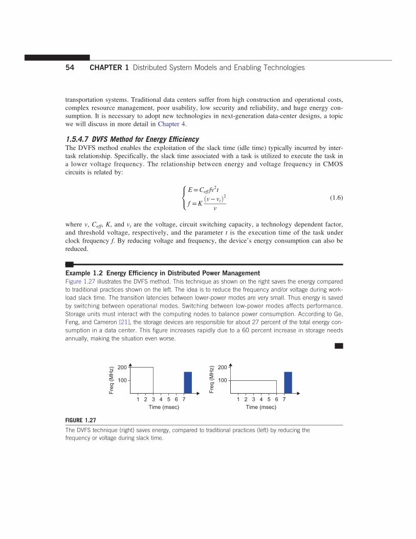
transportation systems. Traditional data centers suffer from high construction and operational costs,complex resource management, poor usability, low security and reliability, and huge energy con-sumption. It is necessary to adopt new technologies in next-generation data-center designs, a topicwe will discuss in more detail in Chapter 4.
1.5.4.7 DVFS Method for Energy EfficiencyThe DVFS method enables the exploitation of the slack time (idle time) typically incurred by inter-task relationship. Specifically, the slack time associated with a task is utilized to execute the task ina lower voltage frequency. The relationship between energy and voltage frequency in CMOScircuits is related by:
E=Ceff fv2t
f =Kðv− vtÞ2
v
8<: (1.6)
where v, Ceff, K, and vt are the voltage, circuit switching capacity, a technology dependent factor,and threshold voltage, respectively, and the parameter t is the execution time of the task underclock frequency f. By reducing voltage and frequency, the device’s energy consumption can also bereduced.
Example 1.2 Energy Efficiency in Distributed Power Management
Figure 1.27 illustrates the DVFS method. This technique as shown on the right saves the energy comparedto traditional practices shown on the left. The idea is to reduce the frequency and/or voltage during work-load slack time. The transition latencies between lower-power modes are very small. Thus energy is savedby switching between operational modes. Switching between low-power modes affects performance.Storage units must interact with the computing nodes to balance power consumption. According to Ge,Feng, and Cameron [21], the storage devices are responsible for about 27 percent of the total energy con-sumption in a data center. This figure increases rapidly due to a 60 percent increase in storage needsannually, making the situation even worse.
200
Fre
q (M
Hz)
100
1 2 3 4
Time (msec)
5 6 7
200
Fre
q (M
Hz)
100
1 2 3 4
Time (msec)
5 6 7
FIGURE 1.27
The DVFS technique (right) saves energy, compared to traditional practices (left) by reducing thefrequency or voltage during slack time.
54 CHAPTER 1 Distributed System Models and Enabling Technologies

1.6 BIBLIOGRAPHIC NOTES AND HOMEWORK PROBLEMSOver the past four decades, parallel processing and distributed computing have been hot topics forresearch and development. Earlier work in parallel computing can be found in several classic books[14,17,27,28]. Recent coverage of distributed systems can be found in [8,13,20,22]. Cluster comput-ing was covered in [2,10,28,38] and grid computing in [6,18,42,47,51]. P2P networks were intro-duced in [6,34,46]. Multicore CPUs and many-core GPU processors were discussed in [15,32,36].Information on the Top 500 supercomputers can be found in [50].Data centers are introduced in [4,19,26], and recent computer architecture in [24,26]. Cloud
computing is studied in [1,9,11,18,29,30,39,44]. The edited volume [11] on cloud computing byBuyya, Broberg, and Goscinski serves as a good resource on cloud computing research. Chou’sbook [12] emphasizes business models for cloud services. Virtualization techniques were introducedin [40–44]. The articles by Bell, Gray, and Szalay [5]; Foster, et al. [18]; and Hey [25] addresscritical issues concerning data-intensive grid and cloud computing. Massive data parallelism andprogramming are covered in [14,32].Distributed algorithms and MPI programming are studied in [3,12,15,22,28]. Distributed operat-
ing systems and software tools are covered in [3,7,13,46]. Energy efficiency and power manage-ment are studied in [21,31,52]. The Internet of Things is studied in [45,48]. The work of Hwangand Li [30] suggested ways to cope with cloud security and data protection problems. In subsequentchapters, additional references will be provided. The following list highlights some internationalconferences, magazines, and journals that often report on the latest developments in parallelism,clusters, grids, P2P systems, and cloud and distributed systems:
• IEEE and Related Conference Publications Internet Computing, TPDS (Transactions onParallel and Distributed Systems), TC (Transactions on Computers), TON (Transactions onNetworking), ICDCS (International Conference on Distributed Computing Systems), IPDPS(International Parallel and Distributed Processing Symposium), INFOCOM, GLOBECOM,CCGrid (Clusters, Clouds and The Grid), P2P Computing, HPDC (High-PerformanceDistributed Computing), CloudCom (International Conference on Cloud Computing Technologyand Science), ISCA (International Symposium on Computer Architecture), HPCA (High-Performance Computer Architecture), Computer Magazine, TDSC (Transactions on Dependableand Secure Computing), TKDE (Transactions on Knowledge and Data Engineering), HPCC(High Performance Computing and Communications), ICPADS (International Conference onParallel and Distributed Applications and Systems), NAS (Networks, Architectures, andStorage), and GPC (Grid and Pervasive Computing)
• ACM, Internet Society, IFIP, and Other Relevant Publications Supercomputing Conference,ACM Transactions on Computing Systems, USENIX Technical Conference, JPDC (Journal ofParallel and Distributed Computing), Journal of Cloud Computing, Journal of DistributedComputing, Journal of Cluster Computing, Future Generation Computer Systems, Journal ofGrid Computing, Journal of Parallel Computing, International Conference on Parallel Processing(ICPP), European Parallel Computing Conference (EuroPAR), Concurrency: Practice andExperiences (Wiley), NPC (IFIP Network and Parallel Computing), and PDCS (ISCA Paralleland Distributed Computer Systems)
1.6 Bibliographic Notes and Homework Problems 55
AcknowledgmentsThis chapter was authored by Kai Hwang primarily. Geoffrey Fox and Albert Zomaya have contrib-uted to Sections 1.4.1 and 1.5.4, respectively. Xiaosong Lou and Lizhong Chen at the University ofSouthern California have assisted in plotting Figures 1.4 and 1.10. Nikzad Babaii Rizvandi and Young-Choon Lee of the University of Sydney have contributed partially to Section 1.5.4. Jack Dongarrahas edited the entire Chapter 1.
References[1] Amazon EC2 and S3, Elastic Compute Cloud (EC2) and Simple Scalable Storage (S3). http://en
.wikipedia.org/wiki/Amazon_Elastic_Compute_Cloud and http://spatten_presentations.s3.amazonaws
.com/s3-on-rails.pdf.[2] M. Baker, R. Buyya, Cluster computing at a glance, in: R. Buyya (Ed.), High-Performance Cluster Com-
puting, Architecture and Systems, vol. 1, Prentice-Hall, Upper Saddle River, NJ, 1999, pp. 3–47, Chapter 1.[3] A. Barak, A. Shiloh, The MOSIX Management System for Linux Clusters, Multi-Clusters, CPU Clusters,
and Clouds, White paper. www.MOSIX.org//txt_pub.html, 2010.[4] L. Barroso, U. Holzle, The Datacenter as a Computer: An Introduction to the Design of Warehouse-Scale
Machines, Morgan & Claypool Publishers, 2009.[5] G. Bell, J. Gray, A. Szalay, Petascale computational systems: balanced cyberstructure in a data-centric
World, IEEE Comput. Mag. (2006).[6] F. Berman, G. Fox, T. Hey (Eds.), Grid Computing, Wiley, 2003.[7] M. Bever, et al., Distributed systems, OSF DCE, and beyond, in: A. Schill (Ed.), DCE-The OSF Distributed
Computing Environment, Springer-Verlag, 1993, pp. 1–20.[8] K. Birman, Reliable Distributed Systems: Technologies, Web Services, and Applications, Springer-Verlag,
2005.[9] G. Boss, et al., Cloud Computing–The BlueCloud Project. www.ibm.com/developerworks/websphere/
zones/hipods/, October 2007.[10] R. Buyya (Ed.), High-Performance Cluster Computing, Vol. 1 and 2, Prentice-Hall, Englewood Cliffs, NJ, 1999.[11] R. Buyya, J. Broberg, A. Goscinski (Eds.), Cloud Computing: Principles and Paradigms, Wiley, 2011.[12] T. Chou, Introduction to Cloud Computing: Business and Technology. Lecture Notes at Stanford Univer-
sity and Tsinghua University, Active Book Press, 2010.[13] G. Coulouris, J. Dollimore, T. Kindberg, Distributed Systems: Concepts and Design, Wesley, 2005.[14] D. Culler, J. Singh, A. Gupta, Parallel Computer Architecture, Kaufmann Publishers, 1999.[15] B. Dally, GPU Computing to Exascale and Beyond, Keynote Address at ACM Supercomputing
Conference, November 2010.[16] J. Dean, S. Ghemawat, MapReduce: Simplified Data Processing on Large Clusters, in: Proceedings of
OSDI 2004. Also, Communication of ACM, Vol. 51, 2008, pp. 107–113.[17] J. Dongarra, et al. (Eds.), Source Book of Parallel Computing, Morgan Kaufmann, San Francisco, 2003.[18] I. Foster, Y. Zhao, J. Raicu, S. Lu, Cloud Computing and Grid Computing 360-Degree Compared, Grid
Computing Environments Workshop, 12–16 November 2008.[19] D. Gannon, The Client+Cloud: Changing the Paradigm for Scientific Research, Keynote Address, IEEE
CloudCom2010, Indianapolis, 2 November 2010.[20] V.K. Garg, Elements of Distributed Computing. Wiley-IEEE Press, 2002.[21] R. Ge, X. Feng, K. Cameron, Performance Constrained Distributed DVS Scheduling for Scientific
Applications on Power-aware Clusters, in: Proceedings Supercomputing Conf., Washington, DC, 2005.
56 CHAPTER 1 Distributed System Models and Enabling Technologies

[22] S. Ghosh, Distributed Systems–An Algorithmic Approach, Chapman & Hall/CRC, 2007.[23] B. He, W. Fang, Q. Luo, N. Govindaraju, T. Wang, Mars: A MapReduce Framework on Graphics
Processor, ACM PACT’08, Toronto, Canada, 25–29 October 2008.[24] J. Hennessy, D. Patterson, Computer Architecture: A Quantitative Approach, Morgan Kaufmann, 2007.[25] T. Hey, et al., The Fourth Paradigm: Data-Intensive Scientific Discovery, Microsoft Research, 2009.[26] M.D. Hill, et al., The Data Center as a Computer, Morgan & Claypool Publishers, 2009.[27] K. Hwang, Advanced Computer Architecture: Parallelism, Scalability, Programming, McGraw-Hill, 1993.[28] K. Hwang, Z. Xu, Scalable Parallel Computing, McGraw-Hill, 1998.[29] K. Hwang, S. Kulkarni, Y. Hu, Cloud Security with Virtualized Defense and Reputation-based Trust
Management, in: IEEE Conference on Dependable, Autonomous, and Secure Computing (DAC-2009),Chengdu, China, 14 December 2009.
[30] K. Hwang, D. Li, Trusted Cloud Computing with Secure Resources and Data Coloring, in: IEEE InternetComputing, Special Issue on Trust and Reputation Management, September 2010, pp. 14–22.
[31] Kelton Research, Server Energy & Efficiency Report. www.1e.com/EnergyCampaign/downloads/Server_Energy_and_Efficiency_Report_2009.pdf, September 2009.
[32] D. Kirk, W. Hwu, Programming Massively Processors: A Hands-on Approach, Morgan Kaufmann, 2010.[33] Y.C. Lee, A.Y. Zomaya, A Novel State Transition Method for Metaheuristic-Based Scheduling in
Heterogeneous Computing Systems, in: IEEE Transactions on Parallel and Distributed Systems, September2008.
[34] Z.Y. Li, G. Xie, K. Hwang, Z.C. Li, Churn-Resilient Protocol for Massive Data Dissemination in P2PNetworks, in: IEEE Trans. Parallel and Distributed Systems, May 2011.
[35] X. Lou, K. Hwang, Collusive Piracy Prevention in P2P Content Delivery Networks, in: IEEE Trans. onComputers, July, 2009, pp. 970–983.
[36] NVIDIA Corp. Fermi: NVIDIA’s Next-Generation CUDA Compute Architecture, White paper, 2009.[37] D. Peleg, Distributed Computing: A Locality-Sensitive Approach, SIAM, 2000.[38] G.F. Pfister, In Search of Clusters, Second ed., Prentice-Hall, 2001.[39] J. Qiu, T. Gunarathne, J. Ekanayake, J. Choi, S. Bae, H. Li, et al., Hybrid Cloud and Cluster Computing
Paradigms for Life Science Applications, in: 11th Annual Bioinformatics Open Source Conference BOSC2010, 9–10 July 2010.
[40] M. Rosenblum, T. Garfinkel, Virtual machine monitors: current technology and future trends, IEEEComputer (May) (2005) 39–47.
[41] M. Rosenblum, Recent Advances in Virtual Machines and Operating Systems, Keynote Address, ACMASPLOS 2006.
[42] J. Smith, R. Nair, Virtual Machines, Morgan Kaufmann, 2005.[43] B. Sotomayor, R. Montero, I. Foster, Virtual Infrastructure Management in Private and Hybrid Clouds,
IEEE Internet Computing, September 2009.[44] SRI. The Internet of Things, in: Disruptive Technologies: Global Trends 2025, www.dni.gov/nic/
PDF_GIF_Confreports/disruptivetech/appendix_F.pdf, 2010.[45] A. Tanenbaum, Distributed Operating Systems, Prentice-Hall, 1995.[46] I. Taylor, From P2P to Web Services and Grids, Springer-Verlag, London, 2005.[47] Twister, Open Source Software for Iterative MapReduce, http://www.iterativemapreduce.org/.[48] Wikipedia. Internet of Things, http://en.wikipedia.org/wiki/Internet_of_Things, June 2010.[49] Wikipedia. CUDA, http://en.wikipedia.org/wiki/CUDA, March 2011.[50] Wikipedia. TOP500, http://en.wikipedia.org/wiki/TOP500, February 2011.[51] Y. Wu, K. Hwang, Y. Yuan, W. Zheng, Adaptive Workload Prediction of Grid Performance in
Confidence Windows, in: IEEE Trans. on Parallel and Distributed Systems, July 2010.[52] Z. Zong, Energy-Efficient Resource Management for High-Performance Computing Platforms, Ph.D.
dissertation, Auburn University, 9 August 2008.
References 57

HOMEWORK PROBLEMSProblem 1.1Briefly define the following basic techniques and technologies that represent recent related advancesin computer architecture, parallel processing, distributed computing, Internet technology, andinformation services:
a. High-performance computing (HPC) systemb. High-throughput computing (HTC) systemc. Peer-to-peer (P2P) networkd. Computer cluster versus computational gride. Service-oriented architecture (SOA)f. Pervasive computing versus Internet computingg. Virtual machine versus virtual infrastructureh. Public cloud versus private cloudi. Radio-frequency identifier (RFID)j. Global positioning system (GPS)k. Sensor networkl. Internet of Things (IoT)m. Cyber-physical system (CPS)
Problem 1.2Circle only one correct answer in each of the following two questions:
1. In the 2009 Top 500 list of the fastest computer systems, which architecture dominates?a. Symmetric shared-memory multiprocessor systems.b. Centralized massively parallel processor (MPP) systems.c. Clusters of cooperative computers.
2. In a cloud formed by a cluster of servers, all servers must be selected as follows:a. All cloud machines must be built on physical servers.b. All cloud machines must be built with virtual servers.c. The cloud machines can be either physical or virtual servers.
Problem 1.3An increasing number of organizations in industry and business sectors adopt cloud systems.Answer the following questions regarding cloud computing:
a. List and describe the main characteristics of cloud computing systems.b. Discuss key enabling technologies in cloud computing systems.c. Discuss different ways for cloud service providers to maximize their revenues.
Problem 1.4Match 10 abbreviated terms and system models on the left with their descriptions on the right. Enterthe description label (a, b, c, …, j) in the underlined blanks in front of the terms.
58 CHAPTER 1 Distributed System Models and Enabling Technologies

______Globus (a) A scalable software platform promoted by Apache for web users to write andrun applications over vast amounts of distributed data
______BitTorrent (b) A P2P network for MP3 music delivery with a centralized directory server______Gnutella (c) The programming model and associated implementation by Google for
distributed mapping and reduction of very large data sets______EC2 (d) A middleware library jointly developed by USC/ISI and Argonne National Lab for
grid resource management and job scheduling______TeraGrid (e) A distributed storage program by Google for managing structured data that can
scale to very large sizes______EGEE (f) A P2P file-sharing network using multiple file index trackers______Hadoop (g) A critical design goal of clusters of computers to tolerate nodal faults or recovery
from host failures______SETI@home (h) The service architecture specification as an open grid standard______Napster (i) An elastic and flexible computing environment that allows web application
developers to acquire cloud resources effectively______BigTable (j) A P2P grid over 3 million desktops for distributed signal processing in search of
extraterrestrial intelligence
Problem 1.5Consider a multicore processor with four heterogeneous cores labeled A, B, C, and D. Assume cores Aand D have the same speed. Core B runs twice as fast as core A, and core C runs three times faster thancore A. Assume that all four cores start executing the following application at the same time and nocache misses are encountered in all core operations. Suppose an application needs to compute the squareof each element of an array of 256 elements. Assume 1 unit time for core A or D to compute the squareof an element. Thus, core B takes 12 unit time and core C takes
13 unit time to compute the square of an
element. Given the following division of labor in four cores:
Core A 32 elementsCore B 128 elementsCore C 64 elementsCore D 32 elements
a. Compute the total execution time (in time units) for using the four-core processor to compute thesquares of 256 elements in parallel. The four cores have different speeds. Some faster cores finishthe job and may become idle, while others are still busy computing until all squares are computed.
b. Calculate the processor utilization rate, which is the total amount of time the cores are busy (notidle) divided by the total execution time they are using all cores in the processor to execute theabove application.
Problem 1.6Consider parallel execution of an MPI-coded C program in SPMD (single program and multipledata streams) mode on a server cluster consisting of n identical Linux servers. SPMD mode means
Homework Problems 59

the same MPI program is running simultaneously on all servers but over different data sets ofidentical workloads. Assume that 25 percent of the program execution is attributed to the executionof MPI commands. For simplicity, assume that all MPI commands take the same amount of execu-tion time. Answer the following questions using Amdahl’s law:
a. Given that the total execution time of the MPI program on a four-server cluster is T minutes,what is the speedup factor of executing the same MPI program on a 256-server cluster,compared with using the four-server cluster? Assume that the program execution is deadlock-free and ignore all other runtime execution overheads in the calculation.
b. Suppose that all MPI commands are now enhanced by a factor of 2 by using active messagesexecuted by message handlers at the user space. The enhancement can reduce the executiontime of all MPI commands by half. What is the speedup of the 256-server cluster installedwith this MPI enhancement, computed with the old 256-server cluster without MPIenhancement?
Problem 1.7Consider a program for multiplying two large-scale N × N matrices, where N is the matrix size. Thesequential multiply time on a single server is T1 = cN3 minutes, where c is a constant determined bythe server used. An MPI-code parallel program requires Tn = cN3/n + dN2/n0.5 minutes to completeexecution on an n-server cluster system, where d is a constant determined by the MPI version used.Assume the program has a zero sequential bottleneck (α = 0). The second term in Tn accounts forthe total message-passing overhead experienced by n servers.Answer the following questions for a given cluster configuration with n = 64 servers, c = 0.8,
and d = 0.1. Parts (a, b) have a fixed workload corresponding to the matrix size N = 15,000. Parts(c, d) have a scaled workload associated with an enlarged matrix size N′ = n1/3 N = 641/3 × 15,000 =4 × 15,000 = 60,000. Assume the same cluster configuration to process both workloads. Thus, thesystem parameters n, c, and d stay unchanged. Running the scaled workload, the overhead alsoincreases with the enlarged matrix size N′.
a. Using Amdahl’s law, calculate the speedup of the n-server cluster over a single server.b. What is the efficiency of the cluster system used in Part (a)?c. Calculate the speedup in executing the scaled workload for an enlarged N′ × N′ matrix on thesame cluster configuration using Gustafson’s law.
d. Calculate the efficiency of running the scaled workload in Part (c) on the 64-processor cluster.e. Compare the above speedup and efficiency results and comment on their implications.
Problem 1.8Compare the similarities and differences between traditional computing clusters/grids and thecomputing clouds launched in recent years. Consider all technical and economic aspects as listedbelow. Answer the following questions against real example systems or platforms built in recentyears. Also discuss the possible convergence of the two computing paradigms in the future.
a. Hardware, software, and networking supportb. Resource allocation and provisioning methods
60 CHAPTER 1 Distributed System Models and Enabling Technologies

c. Infrastructure management and protectiond. Support of utility computing servicese. Operational and cost models applied
Problem 1.9Answer the following questions regarding PC and HPC systems:
a. Explain why PCs and HPCs were evolutionary rather than revolutionary in the past 30 years.b. Discuss the drawbacks in disruptive changes in processor architecture. Why is the memory walla major problem in achieving scalable changes in performance?
c. Explain why x-86 processors are still dominating the PC and HPC markets.
Problem 1.10Multicore and many-core processors have appeared in widespread use in both desktop computersand HPC systems. Answer the following questions regarding advanced processors, memory devices,and system interconnects:
a. What are the differences between multicore CPUs and GPUs in terms of architecture and usage?b. Explain why parallel programming cannot match the progress of processor technology.c. Suggest ideas and defend your argument with some plausible solutions to this mismatch problembetween core scaling and effective programming and use of multicores.
d. Explain why flash memory SSD can deliver better speedups in some HPC or HTC applications.e. Justify the prediction that InfiniBand and Ethernet will continue to dominate the HPC market.
Problem 1.11In Figure 1.7, you studied five categories of modern processors. Characterize in Table 1.9 fivemicro-architectures for designing these processors. Comment on their advantages/shortcomingsand identify the names of two example commercial processors that are built in each processorcategory. Assume a single core in the superscalar processor and the three multithreaded proces-sors. The last processor category is a multicore CMP and each core is assumed to handle onethread at a time.
Table 1.9 Comparison of Five Micro-architectures for Modern Processors
Processor Micro-architecturesArchitectureCharcteristics
Advantages/Shortcomings
RepresentativeProcessors
Single-threaded Superscalar
Fine-grain Multithreading
Coarse-grain Multithreading
Simultaneous Multithreading (SMT)
Multicore Chip Multiprocessor (CMP)
Homework Problems 61
Problem 1.12Discuss the major advantages and disadvantages in the following areas:
a. Why are virtual machines and virtual clusters suggested in cloud computing systems?b. What breakthroughs are required to build virtualized cloud systems cost-effectively?c. What are the impacts of cloud platforms on the future of the HPC and HTC industry?
Problem 1.13Characterize the following three cloud computing models:
a. What is an IaaS (Infrastructure-as-a-Service) cloud? Give one example system.b. What is a PaaS (Platform-as-a-Service) cloud? Give one example system.c. What is a SaaS (Software-as-a-Service) cloud? Give one example system.
Problem 1.14Briefly explain each of the following cloud computing services. Identify two cloud providers bycompany name in each service category.
a. Application cloud servicesb. Platform cloud servicesc. Compute and storage servicesd. Collocation cloud servicese. Network cloud services
Problem 1.15Briefly explain the following terms associated with network threats or security defense in a distribu-ted computing system:
a. Denial of service (DoS)b. Trojan horsec. Network wormd. Service spoofinge. Authorizationf. Authenticationg. Data integrityh. Confidentiality
Problem 1.16Briefly answer the following questions regarding green information technology and energy effi-ciency in distributed systems:
a. Why is power consumption critical to data-center operations?b. What constitutes the dynamic voltage frequency scaling (DVFS) technique?c. Conduct in-depth research on recent progress in green IT research, and write a report on itsapplications to data-center design and cloud service applications.
62 CHAPTER 1 Distributed System Models and Enabling Technologies

Problem 1.17Compare GPU and CPU chips in terms of their strengths and weaknesses. In particular, discuss thetrade-offs between power efficiency, programmability, and performance. Also compare variousMPP architectures in processor selection, performance target, efficiency, and packaging constraints.
Problem 1.18Compare three distributed operating systems: Amoeba, DCE, and MOSIX. Research their recentdevelopments and their impact on applications in clusters, grids, and clouds. Discuss the suitabilityof each system in its commercial or experimental distributed applications. Also discuss eachsystem’s limitations and explain why they were not successful as commercial systems.
Homework Problems 63

This page intentionally left blank