part vii –technical specifications - marine department · supervision and quality control work in...
TRANSCRIPT

Tender Ref.: Marine Department Shipbuilding Tender No. 6/2016
Part VII –Technical Specifications
Part VII – Technical Specifications Page 1 of 62 Supply of Four (4) High Speed Pursuit Crafts for the Customs & Excise Department

Tender Ref.: Marine Department Shipbuilding Tender No. 6/2016
Table of Contents
CHAPTER 1 GENERAL PROVISIONS 1.1 INTRODUCTION 1.2 STATEMENT OF PURPOSES OF THE VESSEL 1.3 AUTHORITIES 1.4 SHIPYARD 1.5 DESIGN AND CONSTRUCTION RESPONSIBILITY 1.6 SURVEY AND INSPECTION 1.7 OFFICIAL SEA TRILA AND SPEED REQUIREMENTS 1.8 ACCEPTANCE AND DELIVERY 1.9 WARRANTY SERVICES DURING THE WARRANTY PERIOD 1.10 SUPPORT SERVICES CHAPTER 2 GENERAL TECHNICAL REQUIREMENTS 2.1 GUIDANCE GENERAL ARRANGEMENT PLAN 2.2 INTRODUCTION AND GENERAL DESCRIPTION 2.3 VESSEL OPERATION 2.4 OPERATING CONDITIONS 2.5 WEIGHT AND LOAD CONDITIONS 2.6 VESSEL SYSTEM REQUIREMENTS 2.7 GENERAL REQUIREMENTS FOR DESIGN AND CONSTRUCTION 2.8 PRINCIPAL CHARACTERISTICS 2.9 RULES AND REGULATIONS 2.10 EQUIPMENT, MACHINERY AND MATERIALS 2.11 RELIABILITY AND MAINTAINABILITY 2.12 NOISE AND VIBRATION 2.13 ACCESS 2.14 STABILITY 2.15 WATER TIGHT/WEATHER TIGHT REQUIREMENTS 2.16 WELDING 2.17 FASTENERS 2.18 MATERIALS 2.19 PAINTING 2.20 MARKINGS AND COLOUR SCHEME 2.21 BOAT IDENTIFICATION PLAQUE 2.22 CATHODIC PROTECTION
Part VII – Technical Specifications Page 2 of 62 Supply of Four (4) High Speed Pursuit Crafts for the Customs & Excise Department

Tender Ref.: Marine Department Shipbuilding Tender No. 6/2016
CHAPTER 3 GENERAL ARRANGEMENTS AND STRUCTURE 3.1 GENERAL PRINCIPLES 3.2 HULL AND DECKHOUSE STRUCTURE 3.3 VESSEL DESIGN 3.4 CONSTRUCTION 3.5 WHEELHOUSE 3.6 MAIN DECK 3.7 ACCOMODATION 3.8 TANK COMPARTMENT 3.9 ENGINE ROOM 3.10 FOREPEAK 3.11 ACCESS AND HANDRAILS 3.12 LOCKERS 3.13 FOAM-FILLED BUOYANCY TUBE/FENDER CHAPTER 4 PROPULSION 4.1 PROPULSION PLANT 4.2 STEERING SYSTEM 4.3 FUEL SYSTEM AND DIESEL TANK
4.4 MACHINERY SEA WATER COOLING SYSTEM
4.5 MAIN ENGINE AND DIESEL GENERATOR EXHAUST SYSTEM CHAPTER 5 ELECTRICAL POWER GENERATION AND DISTRIBUTION SYSTEM 5.1 GENERAL 5.2 PROTECTIVE DEVICES FOR ELECTRIC CIRCUITS 5.3 WIRING AND ELECTRIC CABLE 5.4 ELECTRICAL DESIGNATION AND MARKING 5.5 POWER GENERATION 5.6 BATTERIES AND BATTERY CHARGING 5.7 POWER DISTRIBUTION 5.8 LIGHTING CHAPTER 6 LIFE-SAVING APPLIANCES AND PORTABLE FIRE-FIGHTING EQUIPMENT
6.1 GENERAL PROVISIONS 6.2 MINIMUM LIFE-SAVING APPLIANCES 6.3 MINIMUM PORTABLE FIRE-FIGHTING EQUIPMENT
CHAPTER 7 ELECTRONIC NAVIGATIONAL EQUIPMENT 7.1 REQUIREMENTS OF ELECTRONIC NAVIGATIONAL EQUIPMENT 7.2 DESIGN STANDARDS 7.3 INSTALLATION STANDARDS 7.4 ACCEPTANCE TEST 7.5 ELECTRONIC NAVIGATIONAL EQUIPMENT SPECIFICATIONS
Part VII – Technical Specifications Page 3 of 62 Supply of Four (4) High Speed Pursuit Crafts for the Customs & Excise Department

Tender Ref.: Marine Department Shipbuilding Tender No. 6/2016
CHAPTER 8 AUXILIARY SYSTEMS
8.1 BILGE AND SEA WATER FIREFIGHTING SYSTEM
8.2 FRESH WATER AND BLACK/GREY WATER SYSTEM
8.3 FIXED FIRE FIGHTING EXTINGUISHING SYSTEMS AND ENGINE ROOM VENTILATION SYSTEM
8.4 ANCHORING SYSTEM
8.5 STRONG POINTS – ANCHORING, MOORING, SIDE TOWING AND LIFTING POINTS
8.6 AIR CONDITIONING SYSTEM
CHAPTER 9 SERVICES SUPPORT
9.1 GENERAL PHILOSOPHY
9.2 INFORMATION TO BE PROVIDED PRIOR TO AND AT DELIVERY ACCEPTANCE
CHAPTER 10 TRAINING
10.1 TRAINING ON ELECTRONIC NAVIGATIONAL EQUIPMENT
10.2 TRAINING FOR HANDLING AND MAINTENANCE OF THE VESSEL
CHAPTER 11 ABBREVIATIONS
ANNEXES
ANNEX 1 WARRANTY SERVICES AND GUARANTEE SLIPPING ANNEX 2 IMPLEMENTATION TIMETABLE ANNEX 3 DRAWINGS SUBMISSION TIMETABLE ANNEX 4 MAIN ITEMS INSPECTION TIMETABLE ANNEX 5 CONDITIONS FOR OFFICIAL SEA TRIAL ANNEX 6 ENDURANCE AND PERFORMANCE TESTS ANNEX 7 AS-FITTED DRAWINGS AND MACHINERY/EQUIPMENT DOCUMENTS AND
INFORMATION LITERATURE TO BE DELIVERED TO THE GOVERNMENT AFTER DELIVERY ACCEPTANCE
ANNEX 8 DEFINITIONS OF WAVE AND SEA ANNEX 9 LIST OF GOVERNMENT DOCKYARD CONTRACTORS
Part VII – Technical Specifications Page 4 of 62 Supply of Four (4) High Speed Pursuit Crafts for the Customs & Excise Department

Tender Ref.: Marine Department Shipbuilding Tender No. 6/2016
CHAPTER 1 - GENERAL PROVISIONS
1.1 INTRODUCTION
1.1.1 This document (or “Technical Specifications” (TS)) sets out the requirements of the Government in relation to four (4) aluminium high speed pursuit crafts (viz., “Vessel”) for use by the Customs & Excise Department (“C&ED” or the “user department”).
1.1.2 Unless otherwise specified in the Technical Specifications, all the specifications stated in this Part VII of the Tender Documents are classified and labelled as follows:
(i) (ii)
Essential Requirements [E]; and Those specifications that are not labelled with [E] shall equally form part of the Contract like the specifications labelled as [E], but the Government will not conduct checks at the tendering stage whether the products offered comply with those specifications not labelled with [E].
1.1.3 All this TS shall form part of the Contract. As part of the tender evaluation during the tendering stage (Stage of the tender evaluation), the Tenderer shall submit all the information sufficiently detailed to substantiate that the product and the services offered meet the Essential Requirements as stipulated in Annex C to the Conditions of Tender, failing which its tender will not be considered further.
1.1.4 All Technical Specifications, including the desirable requirements labelled with [D] (if and to the extent the Contractor has indicated compliance in its tender), which are not classified as Essential Requirements shall also form part of the Contract and be of equal materiality and importance upon the award of the Contract. The non-compliance with any specifications set out in these Technical Specifications shall have the same consequences as specified in the Contract. Save during the tendering stage in the manner as mentioned above, no differentiation shall be made based on the classification unless otherwise expressly specified.
1.1.5 The Vessel shall be Ready for Use before the Delivery Date and delivered by the Delivery Date as per the schedule stipulated under Schedule 2 – Delivery Schedule of Part V.
1.1.6 Unless otherwise expressly defined in the Contract, all technical terms and expressions used in the TS shall be interpreted in accordance with the professional or common usage in naval architecture, marine engineering, nautical navigation and the shipbuilding industry.
1.2 STATEMENT OF PURPOSES OF THE VESSEL
1.2.1 The Vessel shall be used by C&ED to conduct patrol, pursuit, interception and stopping of vessels engaged in illegal activities within Hong Kong Waters.
1.3 AUTHORITIES
1.3.1 The Government New Construction Section (GNC) of the Marine Department (MD) is the section responsible for the procurement of the Vessel for the Government of the Hong Kong Special Administrative Region (HKSAR) of the People’s Republic of China (hereinafter referred to as the Government).
1.3.2 GNC may delegate the supervision work including plan reviewing work during the construction stage to private consultancy firms to act on behalf of the Government.
1.3.3 The Electrical and Mechanical Services Department (EMSD) is the Department which will oversee the communication equipment and Electronic Navigational Equipment (“ENE”) technical acceptance.
1.4 SHIPYARD
1.4.1 The Tenderer’s shipyard must have the essential shipbuilding and workshop facilities such as lifting gears, hull construction and calibration equipment, machinery installation and calibration equipment and vessel launching or slipping facilities. [E]
Part VII – Technical Specifications Page 5 of 62 Supply of Four (4) High Speed Pursuit Crafts for the Customs & Excise Department

Tender Ref.: Marine Department Shipbuilding Tender No. 6/2016
1.4.2 The Contractor shall employ a team of professional staff to carry out the design of the Vessel and also carry out
supervision and quality control work in the course of Vessel construction.
1.5 DESIGN AND CONSTRUCTION RESPONSIBILITY
1.5.1 It is the SOLE responsibility of the Contractor to supply a Vessel which is safe, fit and suitable for the operation of the user department and which meets all the relevant regulations and the specifications in these TS including the desirable requirements (if and to the extent the Contractor has indicated compliance in its tender), which include without limitation requirements for safety, health, environmental protection, hull form design features, structure, method and materials for construction and fitting out, stability, sub-division and operational efficiency.
1.5.2 The Vessel shall be designed and constructed in accordance with the latest edition of the rules and regulations of a Recognised Organisation (RO). References to “RO” in this TS shall mean the RO as specified in Schedule 9 of Part V. References to “RO Requirements” shall mean the requirement of the rules and regulations of the RO as specified in Schedule 9 of Part V.
1.5.3 The Vessel is required to be issued with a certificate of class (without conditions) with notation by the RO as specified in Schedule 9 of Part V. All plans, particulars and documentations which are required for the classification of the Vessel by the RO, in addition to those listed in Annex 3 to this Part shall be approved by the RO before submission to MD for endorsement and final approval prior to commencement of work. Any subsequent modifications or additions are to be treated in the same manner. Those drawings which are not required under ship classification approval shall be submitted to MD for approval before work is carried out.
1.5.4 Notwithstanding the submission of the preliminary plans and drawings by the Contractor then as part of its tender for the Contract, all plans and drawings of the Vessel including the design stresses and scantling, shall be submitted to GNC for approval before completion of the Vessel design. The design stresses and scantling including internal structural members shall be determined according to the rules of the RO.
1.5.5 The Contractor shall design, build and supply the Vessel in full compliance with the requirements given in these TS which, to that extent, may be over and above what is normally required by any statutory and RO’s rules and regulations. Should there be any contradiction between the rules and regulations of the RO and the TS, the TS shall prevail unless GNC stipulates or agrees otherwise.
1.5.6 Even if the Contractor may appoint a Sub-contractor to design the Vessel with the prior written consent of the Government, the Contractor shall not be relieved of its obligations under the Contract through such appointment, and the Contractor shall be responsible for all acts, defaults and omissions of the sub-contractor as if they were its own.
1.6 SURVEY AND INSPECTION
1.6.1 Tenderers shall note that the unit price per Vessel quoted in Schedule 1 – Price Schedule in Part V shall be deemed to have included the cost of surveys to be carried out by the relevant RO in respect of that Vessel (if required to be arranged by the Contractor under the Contract).
1.6.2 All electronic items and their installations shall be approved and inspected by EMSD or EMSD representatives as part of the Technical Acceptance.
1.6.3 Subject to Paragraph 1.6.7 of this Chapter, an advance written notice of not less than five working days (if the Vessel is located in Asia), and ten working days (if the Vessel is located other than Asia) must be given to GNC before the representatives of GNC and other Government officers are invited to conduct a survey visit of the Vessel. The Contractor shall be fully responsible for any delay if the Contractor fails to give adequate notice as aforesaid.
1.6.4 The Contactor shall provide
(i) an Implementation Timetable, in the form set out in Annex 2 to the TS, setting out the major milestones and their scheduled completion dates and incorporating the Delivery Dates specified in Schedule 2 of Part V;
(ii) the Drawing Submissions Timetable in the form set out in Annex 3 to the TS; and (iii) Main Items Inspection Timetable in the form set out in Annex 4 to the TS.
Each one of the above shall be submitted to GNC for approval as specified in Clause 11 of the Conditions of
Contract.
Part VII – Technical Specifications Page 6 of 62 Supply of Four (4) High Speed Pursuit Crafts for the Customs & Excise Department

Tender Ref.: Marine Department Shipbuilding Tender No. 6/2016
The Delivery Date(s) for the Vessel as stated in the Implementation Timetable shall be no later than those set out in Schedule 2 of Part V. The Implementation Timetable – mentioned in (i) shall also be consistent with the summary table of survey visits set out in Schedule 10 of Part V and the two timetables mentioned in (ii) and (iii) of this paragraph. Notwithstanding anything in the Contract to the contrary, the Government may suspend payment of any of the instalment specified in Schedule 3 of Part V of the Contract if any of the timetables required herein has not been submitted for GNC’s approval or GNC does not approve any of them or if the progress of work does not comply with any of them as approved by GNC.
1.6.5 A weekly work progress report with photos evidencing the progress to sufficient details as agreed by MD is required to be submitted to MD during the construction of the Vessel. The weekly report shall be submitted before noon of every Monday.
1.6.6 MD may designate consultant(s) from private sector who will be authorised to represent the GNC in all technical matters including plan approval related to the construction of the Vessel. The Contractor shall cooperate with the consultant(s) and afford them unhindered access to the Vessel at all times during working hours, and shall furnish them with current copies of all drawings, sketches, correspondence, change notices, change orders, test agendas, schedules etc.
1.6.7 After arriving at the site for a survey visit, if MD / C&ED officer / consultant considers it is unsafe to carry out the test or inspection, the test/inspection will not be carried out. The Contractor shall arrange another additional survey visit at the Contractor’s expenses. The Government shall not be responsible for any delay arising from any postponement in conducting the survey visit due to any safety issue as specified in this paragraph.
1.6.8 Where any fee charge and associated expense are payable for the services of an RO which are necessary in order to fulfil any obligation of the Contractor under the Contract, the Contractor is responsible for paying the RO all such fees, charges and associated expenses. Such fees shall include charges for drawing approval, surveys (if deemed necessary), issue of certificates, and any other expenses payable to the RO.
1.6.9 The Contractor shall provide offices space for MD officers and consultants during their survey visits and construction progress visits to the Vessel at the shipyard where the Vessel is constructed. The office space shall include, but not be limited to, two (2) desks, four (4) chairs, one (1) telephone, one (1) conference table for ten persons, drinking facilities, power supply and one (1) cupboard for storage of documents and working clothes. The space provided by the Contractor shall also be fitted with air conditioning, have Internet access, a copying and a printer machine. Cleaning of the space shall be carried out in each working day.
1.6.10 The hours of work of MD officers, C&E officers or consultants will be arranged to coincide with those of the shipyard, in so far as it is practicable to do so. It is intended that all reasonable steps be taken so that the duties of the MD officers, C&ED officers and consultants can be carried out with a maximum of efficiency and a minimum of interference with the Contractor’s work.
1.7 OFFICIAL SEA TRIAL AND SPEED REQUIREMENTS
1.7.1 The Contractor shall submit for MD approval, an Official Sea Trial programme 14 working days in advance of the Official Sea Trial, which shall include details of proposed procedures for carrying out the Official Speed Trial, endurance, ship handling at sea and performance tests, manoeuvring test, crash stop test, astern running test / emergency steering test, anchoring tests and other tests as stated in this paragraph. This programme must be submitted to MD in not less than 14 working days before the trials commence. The notification for Official Sea Trial shall be included evidence that the Vessel is safe to go to sea for the intended tests and trials specified in the Contract.
1.7.2 Like all other tests and trials to be conducted as part of the Technical Acceptance, the Contractor is required to carry out the full Official Sea Trial in Hong Kong at its own expense (including the expense of fuel, lubrication oil, crew and other necessary expenses), in the presence of MD, C&ED officers and the consultants. The Contractor shall observe the local requirements on navigation before the sea trial, including the third party insurance in accordance with the laws of Hong Kong.
1.7.3 The Contractor shall provide to MD or GNC officers, the name, post, duty and experience of each one of the Contractor’s staff on board the Vessel during the Official Sea Trial to ensure the safe operation of the trial. The number of persons on board during a particular test or trial has to be agreed by the MD/GNC officers. The location of each person on board (which can affect the centre of gravity of the Vessel under trial) will need to be first agreed by the GNC.
Part VII – Technical Specifications Page 7 of 62 Supply of Four (4) High Speed Pursuit Crafts for the Customs & Excise Department

Tender Ref.: Marine Department Shipbuilding Tender No. 6/2016
1.7.4 The Contractor shall provide a trial report to GNC after completion of the above tests. The report shall contain information regarding the method of test, engine(s) running condition, sea, weather and wind conditions, Vessel loading condition, the heeling angles (steady or varying as the case may be) during each forward turning manoeuvre, and any other relevant information as required by GNC or GNC appointed consultant during the tests; and such information shall be prepared in a format agreed by GNC.
1.7.5 Official Speed Trial
(i) The Official Speed Trial shall be carried out in the Hong Kong Waters.
(ii) As part of the Technical Acceptance as specified in Paragraph 1.8.1 of this Chapter 1, the Contractor shall carry out the Official Speed Trial in the presence of GNC officers or their appointed agents.
(iii) The actual mean speed of the Vessel (i.e. NOT theoretical) shall be measured during the Official Speed Trial runs to determine if the Contract Speed can be achieved. The speed calculations must NOT be corrected by wind, wave, tidal current, shallow water effects and weather condition.
(iv) The actual mean speed is to be calculated as the arithmetic mean of not less than FOUR continuous runs, i.e. TWO runs in each direction. The speed for each run shall be taken by measuring the time of the Vessel running for one nautical mile between two poles or other measuring method acceptable to MD.
(v) The Contract Speed is considered not achieved if the Contract Speed cannot be attained during the Official Speed Trial after a total of FIVE runs in each direction.
(vi) The Contract Speed to be achieved by the Vessel in the Official Speed Trial shall be the minimum highest achievable speed of 55 knots with the engine power at 100% Maximum Continuous Rating (MCR) and the Vessel under Official Speed Trial Conditions as stated in Annex 5 to this Part. If the Vessel fails to achieve the minimum highest achievable speed of 55 knots under the aforesaid conditions, the Government will deem that the Vessel has failed to pass the Official Speed Trial and therefore Technical Acceptance.
(vii) The instrument use in measuring the Contract Speed for the Official Speed Trial shall be provided either by:
(a) the Contractor provided that the speed measuring device has been calibrated by a certified body in Hong Kong acceptable to GNC; or
(b) Global Positioning System (GPS) supplied by the Government.
The GPS or Differential Global Positioning System (DGPS), which is properly calibrated (with supporting calibration documents) and installed on board the Vessel, is acceptable to GNC; or other speed measuring methods that are acceptable to GNC.
(viii) The Vessel must be in the trial conditions (see Annex 5 to this Part for the conditions of the trials) during the Official Speed Trial. All Equipment shall also have been passed the Technical Acceptance and be in operation during the Official Sea Trial.
(ix) The speed, time of the day, engine running conditions, sea condition, etc., shall be properly recorded by the Contractor, and signed as witnessed by GNC surveyor (or GNC representatives) during the Official Sea Trial. A copy of the Official Sea Trial Report as required in Paragraph 1.7.6 below shall be given to GNC before Delivery Acceptance.
1.7.6 The following tests shall be conducted and the testing results shall be recorded and form part of the Official Sea Trial Report:
(i) Endurance Test The Endurance Test shall be carried out for different engine loading and speeds to obtain the speed/fuel consumption curves (or data) for the Vessel, with the engine(s) operating within the manufacturer recommended engine operating conditions. The test results shall be recorded in accordance with the requirements stipulated in Annex 6 to this Part. The report submitted shall include a curve or curves showing ship speed versus propulsion engine(s) rpm and power, with particulars of the vessel loading and displacement in the test(s).
Part VII – Technical Specifications Page 8 of 62 Supply of Four (4) High Speed Pursuit Crafts for the Customs & Excise Department

Tender Ref.: Marine Department Shipbuilding Tender No. 6/2016
(ii) Manoeuvrability Test Forward turning circle tests to port and starboard sides shall be carried out with : (a) both engines running, and (b) single engine running. The minimum time for turning to both sides at 15°, 90°, 180°, 270° and 360°shall be recorded.
(iii) Crash Stop Test The minimum time and distance achievable by the Vessel when running from full ahead to stop, and then to full astern shall be determined at the Crash Stop Test. (see Paragraph 2.6.2(v))
(iv) Astern Running Test / Emergency Steering Test The maximum astern running speed achievable by the Vessel shall be determined by the test. Also an emergency steering test shall be carried out to ascertain satisfactory emergency steering operations shall be carried out.
(v) Starting Tests for Main Engines and Electric Generator Engines according to RO Requirements.
(vi) Anchoring Test according to RO Requirements.
(vii) Noise level measurement according to the requirements stipulated in Paragraph 2.12.2 of Chapter 2 of this Part.
1.8 ACCEPTANCE AND DELIVERY
1.8.1 Technical Acceptance
(i) This includes all the hull construction, mechanical and electrical tests and trials as required in this Part and those considered necessary by the Government, including equipment tests, anchoring tests, inclining experiment and bottom survey on the slipway in Hong Kong, the Official Speed Trial as mentioned in Paragraphs 1.7.5 of this Chapter shall be conducted in Hong Kong Waters, the Endurance Test, Manoeuvrability and Crash Stop Tests as mentioned in Paragraphs 1.7.6 (i) to (iii), the bench acceptance test and on-site commissioning test for ENE as mentioned in Chapter 7 of this Part and all other verification tests to determine whether or not the Vessel including the Equipment has been supplied in accordance with all the specifications set out in these Technical Specifications.
(ii) All electronic items and their installations shall be approved and inspected by EMSD as part of the Technical Acceptance.
(iii) The Contractor shall supply all necessary equipment and labour at its own cost for carrying out the tests and trials stated in Paragraph 1.8.1(i) above.
(iv) If the Vessel cannot pass all of the tests comprised in the Technical Acceptance by the Delivery Date specified in the Contract, the options available to the Government are set out in Clause 12 of the Conditions of Contract and other applicable provisions of the Contract.
1.8.2 Delivery Acceptance
(i) The Vessel, after its successful completion of Technical Acceptance shall be delivered at the Contractor's expense to the Government Dockyard. If the delivery of the Vessel in Ready to Use condition is 120 days later than the Delivery Date specified in Schedule 2 of Part V, at the discretion of Government, the Contract may be terminated according to the applicable terms stipulated in the Contract.
(ii) Certificate of class (without conditions) for the Vessel with notations as specified in Schedule 9 of Part V shall be issued by the relevant RO as specified in Schedule 9 of Part V before the Acceptance Certificate is issued by the Government.
(iii) The Delivery Acceptance of the Vessel shall be carried out by GNC in accordance with the terms stipulated in the Contract. The Delivery Acceptance is only completed when the Acceptance Certificate is issued by the Director of Marine.
Part VII – Technical Specifications Page 9 of 62 Supply of Four (4) High Speed Pursuit Crafts for the Customs & Excise Department

Tender Ref.: Marine Department Shipbuilding Tender No. 6/2016
(iv) The Contractor must demonstrate to MD that all hull construction, outfitting, vessel stability, machinery,
electrical and electronic equipment are in good working order; and must hand over the Vessel, its fixtures and Equipment to MD in good and complete condition.
(v) Not later than six weeks before the Delivery Acceptance of the Vessel, the Contractor is required to submit to GNC four copies of the Inventory List covering all items of or relating to the Vessel including all engines, on board equipment, manuals, documentation, spares, stores, and equipment for testing in respect of the entire Vessel. The Inventory List shall be approved by MD seven days before the day of Delivery Acceptance and covers everything which the Contractor is required to deliver under the Contract. At the Delivery Acceptance of the Vessel, the approved Inventory List will be used to check that all the items have been delivered to MD in a satisfactory state. Details of each inventory item shall include: item name, description, type, quantity, manufacture’s name and contact details, part reference number and/or serial number, and the items’ locations in the Vessel.
(vi) The items specified in Paragraph 9.2 of Chapter 9, and all items set out in the Inventory List in the form as approved or stipulated by the Government shall be delivered to MD at the Delivery Acceptance of the Vessel. The Contractor must provide 14 days advance notice in writing for Vessel delivery when the Vessel is considered to be completed in accordance with the Contract and Ready for Use and to be delivered for the Delivery Acceptance. The Government will not accept delivery if after undergoing the tests and trials in the Technical Acceptance, the Government does not consider that the Vessel is in Ready to Use condition.
(vii) On delivery, the Vessel must be in a clean, tidy and fully fitted and operational condition.
1.9 WARRANTY SERVICES DURING THE WARRANTY PERIOD
1.9.1 The Contractor shall either be a Government Recognised Servicing Shipyard, i.e., an approved contractor on the list of Government Dockyard Contractor under “Group/ Category: Hull, Deck & Tailshaft Group II” or, before the signing of the Contract, the Contractor shall have entered into a binding sub-contract with a Government Dockyard Contractor (Group/ Category: Hull, Deck & Tailshaft Group II), which shall provide and is capable of providing the Warranty Services for the Vessel in the Warranty Period. The prevailing list of Government Dockyard Contractor (Group/ Category: Hull, Deck & Tailshaft Group II) is at Annex 9 for reference.
1.9.2 Notwithstanding and without prejudice to the Contractor's obligation to provide the Warranty Services for the Vessel under the Conditions of Contract, the original copy of the manufacturer's warranty certificates and all related manuals and documents in respect of all the Equipment valid for 12 months from the date of Acceptance Certificate of the Vessel, shall be delivered to MD upon Delivery Acceptance.
1.9.3 The full scope of the Warranty Services is set out in Annex 1 to this Part.
1.9.4 The Contractor is responsible for arranging the Vessel for Guarantee Slipping at the end of the 12-month Warranty Period. In addition to any defects which the Contractor may be required to fix under Clause 18 of Part IV (Conditions of Contract), the Contractor shall also be responsible for the rectification of any defects found in the course of Guarantee Slipping. The full scope of the Services to be provided as part of the Guarantee Slipping is set out in Annex 1 to this Part.
1.10 SUPPORT SERVICES
1.10.1 The Vessel must be designed for through life support and easy maintenance in the HKSAR based on an operation profile and minimum life expectancy as mentioned in the TS.
1.10.2 The above applies not only to main engines but also to all other equipment installed in the Vessel. Support and maintenance services must be available (i.e. serviceable) in Hong Kong in respect of all equipment installed in the Vessel and return of the whole or part of the Equipment to the original place of manufacturer or supplier shall not be necessary in order to carry out any repair work.
Part VII – Technical Specifications Page 10 of 62 Supply of Four (4) High Speed Pursuit Crafts for the Customs & Excise Department

Tender Ref.: Marine Department Shipbuilding Tender No. 6/2016
CHAPTER 2 - GENERAL TECHNICAL REQUIREMENTS 2.1 GUIDANCE GENERAL ARRANGEMENT PLAN [D]
Part VII – Technical Specifications Page 11 of 62 Supply of Four (4) High Speed Pursuit Crafts for the Customs & Excise Department

Tender Ref.: Marine Department Shipbuilding Tender No. 6/2016
Part VII – Technical Specifications Page 12 of 62 Supply of Four (4) High Speed Pursuit Crafts for the Customs & Excise Department

Tender Ref.: Marine Department Shipbuilding Tender No. 6/2016
2.2 INTRODUCTION AND GENERAL DESCRIPTION
2.2.1 Description
(i) The Vessel will serve as a maritime law enforcement vessel that will transport and employ C&ED crew for a variety of missions. In particular, the Vessel will provide the C&ED with a versatile, multi-mission platform to perform their duties and missions while operating in littoral waters and in Hong Kong Waters in varying sea and weather conditions.
(ii) The Vessel shall be manned and operated by six C&ED crew. C&ED will operate the Vessel from shore bases. It will employ radar, mission communications, sensors and downlink capabilities for situational awareness and threat detection, and shall be an open architecture design to support incremental improvements.
(iii) The Vessel shall be built in aluminium alloy suitable for use in marine environment. [E]
(iv) The Vessel hull shall be deep V mono-hull shaped planning type; the deadrise angle at transom shall be not less than 18 degrees. [E]
2.3 VESSEL OPERATION
2.3.1 Mission Profile
(i) General The Vessel shall be a reconfigurable, multi-mission, maritime vessel. The Vessel is intended to satisfy multiple capability gaps in infiltration/ex-filtration while substantially increasing open-ocean and littoral mobility.
2.3.2 Concept of Operations
(i) Mission Sets (a) Patrol: Marine patrol involves daily deployment within the Hong Kong Waters to search, detect,
and identify waterborne or on shore targets of interest. This mission provides the situational awareness and intelligence for the development of a comprehensive common operational picture of threats at or near the boundaries of the Hong Kong Waters.
(b) Interdiction: Marine interdiction involves the use of Vessel to pursue, overtake, intercept, and
stop other vessels of interest. Interdiction frequently incorporates maritime use of force that involves the employment of either direct or indirect maritime disabling measures against non-compliant vessels while underway.
2.4 OPERATING CONDITIONS
2.4.1 General
(i) The Vessel deployment can occur at any time day or night, while operating in littoral and polluted waters and in offshore areas of the Hong Kong Waters in varying sea and weather conditions.
(ii) The Vessel shall be able to operate safely in weather conditions up to and including the conditions as defined by values of Beaufort wind force scale (“Beaufort scale”) number 6.
(iii) Vessel’ s normal operating profile is: No. of hours/day : 9 hours engine running time per day No. of days/year : 340 days per year
(iv) Vessel’ s normal daily operating profile is: 3 hours at maximum speed of 55 knots; 3 hours at cruising speed of 35 knots; 3 hours idle conditions.
Part VII – Technical Specifications Page 13 of 62 Supply of Four (4) High Speed Pursuit Crafts for the Customs & Excise Department

Tender Ref.: Marine Department Shipbuilding Tender No. 6/2016
2.4.2 Operation Environment
(i) The Vessel and all of its equipment shall be capable of operating continuously in the following combined environmental conditions:
Temperature: (a) Outside Air (Dry Bulb) 40°C (maximum) to 0°C (minimum); and (b) Sea Water Temperature 30°C (maximum) to 10°C (minimum). Wind Conditions (concurrent with the above temperatures): 30 knots (maximum).
Sea Conditions: (a) Operations – See Paragraph 2.6.1 of this Part. (b) Surf and Breaking Waves: The Vessel is not intended to be operated in surf or breaking waves. Water: The Vessel shall operate in various types of waters. This water is expected to include debris, sand and sea grasses, and may be aerated.
2.5 WEIGHT AND LOAD CONDITIONS
2.5.1 General
(i) Crew weights shall be 100 kg per person (including outfit) when calculating weights.
2.5.2 Definitions of Load Conditions
(i) Light Load Condition: Vessel complete, ready for service in every respect including outfit. Liquids in machinery shall be at operating levels. This condition does not include crew, equipment load, or fuel.
(ii) Full Load Condition: Light Condition plus full fuel, water, six crew and 100 kg of equipment load.
2.6 VESSEL SYSTEM REQUIREMENTS
2.6.1 General
(i) Specified speed, range, and endurance requirements as well as manoeuvring, sea keeping, launch, and recovery requirements, shall be met with the Vessel operating in the Full load Condition.
(ii) When configured in accordance with this specification, the Vessel shall meet or exceed the following
key performance parameters (“KPP”).
(a) KPP 1: Sea Keeping
The Vessel shall be designed, engineered and constructed to operate without substantial damage through sea states up to sea state 3 of Beaufort scale for a cumulative period of nine hours while making headway in full load condition and operate at reduced capacity through sea state up to 6. For these purposes, substantial damage is defined as any damage or structural failure that adversely affects the structural strength, performance, or integrity of the Vessel, thereby rendering it inoperable for the C&ED mission.
(b) KPP 2: Patrol Speed The Vessel shall be capable of performing patrol in the full load condition, maintaining speeds of up to 35 knots with sea state 3.
(c) KPP 3: Intercept Speed The Vessel shall be able to transition from patrol to intercept, to include maintaining speeds of up to 55 knots with sea state 2 in the full load condition.
Part VII – Technical Specifications Page 14 of 62 Supply of Four (4) High Speed Pursuit Crafts for the Customs & Excise Department

Tender Ref.: Marine Department Shipbuilding Tender No. 6/2016
(d) KPP 4: Manoeuvrability The Vessel shall be highly manoeuvrable. Manoeuvrability of the Vessel is critical in those interdiction missions which will often require the engagement of hostile, highly manoeuvrable, and evasive watercraft. The ability to safely and adequately engage these violators hinges on a high level of manoeuvrability appropriate for this length of Vessel.
(e) KPP 5: Endurance / fuel capacity The Vessel shall be shall be capable of 3 hours at 55 knots; 3 hours at 35 knots; 3 hours at idle conditions; and a ten percent usable reserve prior to re-fueling shall be considered.
2.6.2 Manoeuvring
(i) The Vessel shall have waterjet propulsion that assures good manoeuvrability.
(ii) The Vessel shall be dynamically stable at all speeds up to the maximum attainable speed and under all specified load conditions (See Paragraph 2.5.2). Dynamic stability applies to vessel trim, and all motions and accelerations, and shall constitute operation where vessel orientation, motions, and accelerations do not pose a hazard to the crew and which are not otherwise controllable by good seamanship and vessel handling.
(iii) At all speeds and load conditions, the Vessel shall maintain a straight course without corrective
steering and with no more than three (3) degrees of list.
(iv) In turns at all speeds and load conditions, the Vessel shall maintain a steady turn rate without skidding, or any other effects of dynamic instability. Inboard heel shall be maintained throughout turns at speeds above 15 knots.
(v) With waterjet propulsion emergency crash stop operations shall be guaranteed. The Vessel shall stop
within three (3) vessel length from maximum speed without damage or risk for the crew.
2.7 GENERAL REQUIREMENTS FOR DESIGN AND CONSTRUCTION
2.7.1 General
(i) The Vessel shall be designed to withstand the shock and vibration (accelerations) associated with the operations stated in Paragraph 2.3, considering the required weight and load conditions in Paragraph 2.5, the expected annual hours of operation in Paragraph 2.4, and maintain the expected service life.
(ii) All materials and equipment entering into the construction and outfitting of the Vessel shall be new.
2.7.2 Workmanship and materials
(i) All workmanship, materials and equipment installed in or used during construction of the Vessel shall be new, commercially proven with respect to reliability, maintainability, availability, corrosion resistance, and of suitable marine quality for the intended purpose.
(ii) The aluminium alloys shall be of the following types (a) Tube: ASTM B221 (Extruded) 6082-T6, or (Drawn) 5083-H112 ASTM B210 5086-H32.
(b) Plate and Sheet: ASTM B928 Alloy 5086 - H116 or H321 or 5083-H116, H128 or H321. (c) Stiffeners: ASTM B221 (Extruded) Alloy 6082 T6 ; (Drawn) Alloy 5086 - H116 or H321 or
5083-H116, H128 or H321. Aluminium alloys based on other standards may be accepted based on their demonstrated
equivalence to the ones listed above. Part VII – Technical Specifications Page 15 of 62 Supply of Four (4) High Speed Pursuit Crafts for the Customs & Excise Department

Tender Ref.: Marine Department Shipbuilding Tender No. 6/2016
(iii) Initial and long-term aesthetics shall be considered in material, coatings and process selections, as the Vessel will be called upon to be a forward and visible symbol of Hong Kong.
(iv) To the maximum extent possible, all like parts shall be of common use and available on the
worldwide market.
(v) The Vessel shall be fair and free from objectionable buckles or uneven sight edges. Joints shall be neatly and accurately made. Faying surfaces shall be free from gaps, hollows, or warping. Shims shall not be used to correct improper fits. All sharp edges shall be dressed, and/or radiused to avoid personnel injury.
(vi) Non-watertight equipment shall be installed where fluids will not spray, drip, splash, or be blown
into it, or the equipment shall have adequate protection provided.
(vii) Internal and external finishes of components shall be compatible with the Vessel manufacturer’s finish. The Contractor shall provide the colour selection, markings, and paint scheme for the Vessel.
(viii) Where Vessel components and equipment are specified herein by brand name or manufacturer and
model number, such identification is intended to be descriptive, not restrictive, and is intended to indicate the required characteristics of the product. The Contractor may propose the use of other products, which are functionally equivalent to the specified make and model products.
2.8 PRINCIPAL CHARACTERISTICS
2.8.1 The Vessel shall meet the general characteristics as shown in Table 2.1 of this Part. Please see Guidance General Arrangement Plan in paragraph 2.1. Table 2.1 THE VESSEL PRINCIPAL CHARACTERISTICS
Characteristic Requirements Length Overall (from bow to the outermost transom platform) (including fenders)
16.5 m - 17.5 m [E]
Length (from bow to transom) (including fenders)
15.5 m to 16.5 m [E]
Beam (including fenders) 3.8 m – 4.8 m [E]
Draft Design to suit
Depth Design to suit
Full load Displacement (See Paragraph 2.5)
Design to suit
Hull type Monohull deep “V” planing hull
Contract Speed 55 knots when both propulsion engines are running with power at 100% maximum continuous rating (MCR) under the Official Speed Trial conditions as stated in Annex 5 to Part VII. [E]
Cruising Speed 35 knots at full load and sea state 3
Crew capacity 6 crew [E]
Area of Operations Hong Kong Waters
Vessel’ s normal operating profile 340 days per year; 9 hours engine running time per day: -3 hours at maximum speed of 55 knots; -3 hours at cruising speed of 35 knots; -3 hours at idle conditions.
Part VII – Technical Specifications Page 16 of 62 Supply of Four (4) High Speed Pursuit Crafts for the Customs & Excise Department

Tender Ref.: Marine Department Shipbuilding Tender No. 6/2016
Fuel capacity Daily operation plus 10 % reserve without refuelling, a
minimum of 3,000 litres for two tanks
Construction material (Hull and deckhouse) Marine grade aluminium alloy Fendering system Polyethylene foam core coated with polyurethane
elastomer secured by straps to both sides of the hull in sections
Propulsion Two waterjets coupled with marine diesel engines Endurance, normal operating condition Vessel’s normal operating profile with all auxiliaries,
including diesel generator and navigation systems in operation
Towing capacity Capable of safely side towing a vessel of similar size and weight
2.9 RULES AND REGULATIONS
2.9.1 General
(i) The Tenderer shall state in Schedule 9 of Part V which RO and its rules and regulations and class notation shall be used in the design and construction of the Vessel. [E]
(ii) The Vessel is to be designed and constructed according to the latest edition of the rules and regulations of an RO. The class characteristics assigned to the Vessel shall cover:
(a) Hull and stability (b) Machinery and systems (c) Fire protection and escape (d) Materials and welding
(iii) With reference to machinery, systems and fire protection, the Classification Society is to provide specific requirements for the management of the risk due to the presence on board of fuel having low flashpoint.
(iv) Service and navigation notations assigned to the Vessels shall be in line with the operational requirements stated in these Technical Specifications.
2.9.2 Classification:
The Vessel shall be classed with one of the following class notations or equivalent: [E]
ABS A1 AMS Circle E HSC Coastal Craft; Bureau Veritas (BV) Hull Mach Light ship Fast Patrol Vessel; CCS HSC Coastal Service Restriction; DNVGL 1A HSLC Patrol R3; Lloyd’s Register (LR) 100A1 SSC Mono Patrol LDC G2 MCH; RINA PC Hull, Patrol, Maritime Police
2.9.3 Other rules and regulations (i) IACS Shipbuilding and Repairs Quality Standards No. 47. (ii) International Electrotechnical Commission (IEC) Regulations for the Electrical and Electronic
Equipment. (iii) International Telecommunications Union recommendations in the International Radio Regulations
(ITU-R), (iv) International Regulations for Preventing Collisions at Sea 1972 (as amended by IMO Resolution
A464(XII) and A626 (XV)). (v) The Vessel shall be designed and manufactured to at least the standards as specified in these Technical
Specifications. For equipment and fittings which are not specified above, then to at least to one of those standards prescribed by or recommended by the following organisations:
Part VII – Technical Specifications Page 17 of 62 Supply of Four (4) High Speed Pursuit Crafts for the Customs & Excise Department

Tender Ref.: Marine Department Shipbuilding Tender No. 6/2016
(a) BSI British Standards Institute (b) DIN Deutsche Industrie Normen (c) FEM Federation Europeene de la Manutention (d) GB Standardization Administration of the People’s Republic of China (e) IEEE Institute of Electrical and Electronic Engineers (f) ISO International Organization for Standardization (g) JIS Japanese Industrial Standards
(vi) The Contractor shall be required to submit a full list of applicable rules, regulations and standards to be
complied with in the design and constructions of the Vessel during the early design stage of the Vessel.
2.10 EQUIPMENT, MACHINERY AND MATERIALS
2.10.1 All materials, equipment and machinery shall be installed in accordance with the original equipment manufacturers’ recommendations.
2.10.2 To ensure readily available replacement parts, the Contractor shall utilise standardised fittings, equipment, and fabrication methods for all Vessels manufactured as specified herein.
2.11 RELIABILITY AND MAINTAINABILITY
2.11.1 General
(i) The Vessel must be designed for through life support and easy maintenance in the HKSAR, based on operation profile and minimum life expectancy as mentioned in the Technical Specifications.
2.11.2 Reliability and Availability
(i) The availability of both system and components shall be predicated on at least 3,060 hours of operation per year when operated and maintained in accordance with the Contractor’s recommendations. The Contractor shall provide technical documentation on the form of paper studies, quality assurance estimates, engineering projections, or past performance of Vessel calculations based on actual data.
(ii) An operational mission failure is any hardware, software failure, or fault that prevents the component from
meeting operational requirements defined herein. To assist in tracking this reliability there shall be an ability to track Vessel operating hours. Design controllable failures used in determining reliability are:
(a) Design/workmanship failures due to design deficiencies or poor workmanship of the equipment,
component part, or software. (b) Component part failures due to defective component parts. (Note: In the event that several
component parts of the same type fail during test, each one shall be considered as a separate failure, unless it can be shown that one failure caused one or more of the others to fail).
(c) Built-in-Test (BIT) detected failures that result in any hardware being replaced/repaired including the BIT circuitry itself.
(d) Any failure alert generated by the BIT function and not confirmed by detailed maintenance checks shall be considered a failure for reliability calculations.
(e) Connectors/contacts failures caused by faulty, corroded, or contaminated systems replaceable assembly external contacts or connections that cannot be corrected by reseating or treating.
(iii) Equipment shall be designed not to require any periodic adjustments.
2.11.3 Maintainability
(i) All components requiring routine maintenance shall be readily accessible. The installation design of mission system equipment and line replaceable units, subassemblies, and parts shall allow for the easy removal, replacement, and adjustment of equipment on-site or in the field by technicians using standard materials, mechanics tools, and electronic repair equipment. Use of specialised tools shall be avoided.
Part VII – Technical Specifications Page 18 of 62 Supply of Four (4) High Speed Pursuit Crafts for the Customs & Excise Department

Tender Ref.: Marine Department Shipbuilding Tender No. 6/2016
(ii) Access panels and closures shall provide access to components requiring inspection, replacement,
calibration, and adjustment, as well as to disconnect fittings for ease of maintenance and reduction, in maintenance time. Access to compartments that require entrance between scheduled inspections, other than those required to replace a component due to malfunction, shall provide easy entry. Connectors shall be mounted to allow for disconnection and reconnection with minimum effort during component removal. Wiring bundles shall be long enough to permit replacement of connectors multiple times without splicing or before replacing the wire bundles and for ease of access to the component for repair/replacement, i.e. a “service loop”. Wiring bundles shall not be hard wired to any equipment or equipment racks.
(iii) The Vessel systems, equipment, and components shall be designed and arranged to facilitate unobstructed
visual and physical accessibility for operating efficiency and for inspection, adjustment, maintenance, repair, and removal and replacement
(iv) Components requiring routine maintenance shall be readily accessible and removable with hand tools
wherever possible. Examples include changing/checking oil, fuel air filters, and electronics. Basic maintenance, including engine parts change-out, can be accomplished by maintenance personnel.
(v) The Vessel design shall preclude improper mounting, installation, and alignment of systems and their
components.
(vi) The Vessel shall operate for the 300 underway hours without requiring preventive or predictive maintenance actions beyond those included in normal pre-operation and post-operation checks. Examples of preventive and predictive maintenance include planned fluid change, mechanical adjustment, and wear part replacement or inspection.
2.12 NOISE AND VIBRATION
2.12.1 Noise
(i) Excessive noise levels present two risks within Vessel operations. Firstly, they present a health hazard. Secondly, they interfere with crew communications and the use of radio equipment. Noise also presents a nuisance factor, and thereby interferes indirectly with crew performance. Low frequency noise can also have a significant vibration component. Low noise levels are vitally important to mission effectiveness and long term crew health.
2.12.2 Table 2.2 specifies the maximum noise level limits.
Table 2.2 Noise limits for the Vessel
Noise Limits for the Vessel
Area Maximum Limit (dB)
Wheelhouse (measured at maximum speed) 80 dB
Accommodation deck (measured at cruise speed) 80 dB
2.12.3 Vibration
(i) Reducing the injurious effects of exposure to repeated slamming for the Vessel’s crew is a prime consideration. The Vessel design shall incorporate best design practices in terms of shape, form, function, seating concepts, ergonomics, and training specifically intended to counter the physical stress, strain, shock and vibration energies imparted to the crew and passengers.
(ii) No component in the Vessel shall rattle. Mounts for removable components and accessories,
including items moved for towing or transport shall be provided with resilient material as necessary to prevent rattling.
(iii) Mounts for removable components and accessories, including items moved for towing or transport,
shall be provided with resilient material as necessary to prevent rattling. Part VII – Technical Specifications Page 19 of 62 Supply of Four (4) High Speed Pursuit Crafts for the Customs & Excise Department

Tender Ref.: Marine Department Shipbuilding Tender No. 6/2016
(iv) Gaskets shall be used and self-locking fasteners shall be provided to prevent loosening of fasteners under vibration.
2.13 ACCESS
2.13.1 Components requiring routine maintenance (e.g. oil changes, fuel and air filters, electronics, batteries, bilge pumps) shall be readily accessible and removable with standard hand tools whenever possible.
2.13.2 Access to fuel tanks, hoses, and fittings shall be provided for inspection, repair, and maintenance without the removal of permanent structural components (to include piping, wires, ducts and others) and shall be large enough to allow removal of the item without its disassembly
2.13.3 No wiring shall be run on top of the fuel tanks or in the fuel tanks compartments. All wiring shall be run through appropriate rigging hoses or conduit with chafe protection. All wiring shall be secured to minimise movement.
2.13.4 Hatches shall be sealed with a large diameter rubber o-ring type design and shall be equipped with deep gutters for drainage. Hatches shall not slam when dropped.
2.13.5 If utilised, gas shocks shall have stainless steel ends and mounting hardware.
2.13.6 Areas containing sensitive equipment, to include the wheelhouse, shall be equipped with hatches with marinised locking devices.
2.13.7 Bilge areas shall be accessible. Bilge access points shall provide access to the lowest point of the bilge when the Vessel is in the water. The crew shall be able to access bilges without the need of tools.
2.13.8 Locations requiring routine maintenance checks on a daily basis or while underway shall be located so they are readily accessible to the crew.
2.13.9 Access to the wheelhouse shall be through a weather tight door.
2.13.10 Access to the forepeak shall be through a watertight hatch.
2.14 STABILITY
2.14.1 General
(i) The Vessel shall meet the stability and buoyancy requirements of a Classification Society under all load conditions (see Paragraph 2.5.2), regardless of length. If foam fendering is used, it may be included in the flotation calculations.
(ii) The Vessel shall remain afloat with one watertight compartment flooded.
(iii) The Vessel shall have sufficient stability to allow for two crew members to recover a person from the water, alongside the Vessel, in the normal operating condition and calm waters. The Vessel shall be provided with a placard indicating the maximum number of passengers and maximum load in kg determined by means of approved stability studies, which shall specify the number of persons / load in kg that can be accommodated in the accommodation space and on the main deck. The maximum number defined is the maximum approved in intact stability requirement.
(iv) The Vessel shall have no trim and no heel while static in the Full Load Condition.
(v) No ballast shall be installed on the Vessel.
(vi) The tank design shall minimise the free surfaces effects.
Part VII – Technical Specifications Page 20 of 62 Supply of Four (4) High Speed Pursuit Crafts for the Customs & Excise Department

Tender Ref.: Marine Department Shipbuilding Tender No. 6/2016
2.15 WATERTIGHT/WEATHERTIGHT REQUIREMENTS
2.15.1 The main deck shall be watertight.
2.15.2 The deckhouse shall be weathertight.
2.16 WELDING
2.16.1 Welding and fabrication
(i) All welding and fabrication shall be implemented according to the applicable classification requirements.
(ii) Welded joints shall be carefully designed and constructed to conform to the latest established standards to prevent fatigue failure. Cutting for edge preparation shall be performed by qualified person to achieve correct angle, shape and smooth finish of the edges. Only qualified welders shall perform the welding work.
(iii) Certification of the qualifications of each individual welder shall be submitted by the Contractor.
Welds installed using unqualified procedures or welding performed by non-certified welders shall be subject to removal by the Contractor at his own expense.
(iv) The structure fabrication shall include but not be limited to the following:
(a) Inventory of incoming material, consumables components and machinery; (b) Traceability procedures for materials together with traceability identification codes which
shall be serial and indexed to the controlled manufacturing procedures; (c) Lofting, cutting, fit up, welding, forming and dimensions of structural components; (d) Welding and inspection procedures according to classification rules; (e) Welding and inspection personnel qualification and certification; (f) Welding, machining, measuring and inspection equipment maintenance and calibration; (g) Machining, finish surfaces, bolting; (h) Procedures for non-conformance reporting and rectification of defects; (i) Design and manufacturing drawing control and procedures for revisions, updates and reissue
of drawings; (j) Welding processes shall be approved by one of the following Classification Societies:
(1) American Bureau of Shipping ABS (2) Bureau Veritas BV (3) China Classification Society CCS (4) Det Norske Veritas Germanischer Lloyd DNV GL (5) Korean Register of Shipping KR (6) Lloyd's Register of Shipping LR (7) Nippon Kaiji Kyokai NK (8) Registro Italiano Navale RINA (9) Russian Maritime Register of Shipping RS
(k) All materials must be provided with their own certificate of origin.
2.17 FASTENERS
2.17.1 General
(i) All fasteners shall be of corrosion resistant materials.
(ii) Dissimilar metals shall be isolated to prevent galvanic corrosion in accordance with classification rules standard.
(iii) Fasteners shall not be threaded directly into aluminium alloys. Backing plates, alloy 304 stainless steel
helicoil inserts, or galvanically compatible threaded inserts shall be used when direct threading is required.
(iv) Ferrous materials shall not be used as fasteners.
Part VII – Technical Specifications Page 21 of 62 Supply of Four (4) High Speed Pursuit Crafts for the Customs & Excise Department

Tender Ref.: Marine Department Shipbuilding Tender No. 6/2016
(v) Where nuts are inaccessible after construction of the Vessel, they shall be captured to allow
re-assembly and prevent backing off. Unless otherwise specified, self-locking nuts of plastic insert type or all-metal left-locking nuts of distorted type shall be provided to prevent loosening of bolts due to shock and vibration.
(vi) Fasteners in deck traffic areas shall be flush mounted to eliminate tripping hazards.
(vii) Gaskets shall be used and self-locking fasteners shall be provided to prevent loosening of fasteners under vibration.
2.18 MATERIALS
2.18.1 General
(i) The hull and deckhouse construction material shall be new and of a type which has been certificated by Classification Society in accordance with the applicable rules. Mill certificates shall be obtained and records shall be strictly maintained to match these to the various sections produced during Vessel manufacture.
2.18.2 Aluminium
(i) Tube: ASTM B221 (Extruded) 6082-T6, or (Drawn) 5083-H112 ASTM B210 5086-H32.
(ii) Plate and Sheet: ASTM B928 Alloy 5086 - H116 or H321 or 5083-H116, H128 or H321.
(iii) Stiffeners: ASTM B221 (Extruded) Alloy 6082 T6; (Drawn) Alloy 5086 - H116 or H321 or 5083-H116, H128 or H321.
(iv) Alloy 5052 of SAE AMS-QQ-A-250/8 may be used for un-welded sheathing, expanded aluminium
and trim for a thickness less than 1/8 inch.
(v) Alloy 6061-T6 of ASTM B241 may be used for pipes, special structural extrusions and hollow shapes as structural components. If so used, allowable stresses shall be based on the zero temper condition.
(vi) Non-structural items of trim and outfit such as windows and doorframes, castings, and hardware items
may be alloy 6063 or alloy 6061 of ASTM B221 or alloy 356.1, 356.2 or A356.2 of ASTM B179.
(vii) Aluminium of tempers H116 shall pass an appropriate test for resistance to exfoliation corrosion.
(viii) Double plates shall not be used in the construction of the Vessel.
2.18.3 Stainless steel
(i) Wrought: AISI 316L, AISI 302, or AISI 304.
(ii) Pipe or Tubing: ASTM A312 or ASTM A269, Grade 316L, 321 or 347.
(iii) Bars & Shapes: ASTM A276-2a, Grade 316L.
(iv) Wherever stainless steel or corrosion resistant steel is used or required, it shall be as follows: Stainless steel 316L shall be used for welded fittings, couplings, etc. on the exterior of the Vessel above and below the waterline of the hull that is exposed directly to sea water and for all applications on the weather decks unless stated elsewhere in this specification. If stainless steel is used, 316L shall also be used on all interior welded applications in sea water handling systems where direct exposure to sea water is possible. Stainless steel 316 shall be used in non-welded applications where direct contact with sea water or spray is possible. Use of stainless steel 302 or 304 is restricted to interior, non-welded applications where exposure to sea water is not anticipated.
2.18.4 Prohibited materials
(i) The following materials shall not be used in the construction of the Vessel: (a) wood, (b) mercury,
Part VII – Technical Specifications Page 22 of 62 Supply of Four (4) High Speed Pursuit Crafts for the Customs & Excise Department

Tender Ref.: Marine Department Shipbuilding Tender No. 6/2016
(c) pop-rivets, (d) lead paint, (e) cadmium-plated hardware, fittings, washers and fasteners.
(ii) Materials which contain asbestos and refractory fiber materials (also termed ceramic fiber and
aluminium-silica material) shall not be used.
(iii) Fire retardant resins shall not be used.
(v) Any sound attenuating material used on the construction of the Vessel shall: (a) not hinder inspection of the interior hull and hull structure; (b) be resistant to absorbing any type of liquid or vapours; (c) not cause any corrosion to the hull material; and (d) not be combustible/flammable.
2.19 PAINTING
2.19.1 General
(i) The hull painting shall be in compliance with International Convention on the Control of Harmful of Anti-fouling System on Ships.
(ii) Paints shall be of a fire-retarding marine quality and applied in accordance with manufacturer’s
specification.
(iii) Volatile Organic Compounds (VOC) content limits of the paints shall comply with the Controls and Requirements of the VOC Regulation (VOC content limits for regulated vessel paints and regulated pleasure craft paints) of the Regulation of Hong Kong Air Pollution Control Ordinance.
(iv) Painting schedule shall be submitted for GNC approval before the commencement of work. The
proposal shall contain a list and the detailed specification of the paint intended to be used. Thickness of each coating shall be specified.
(v) All painting work shall carry a one-year guarantee provided by the Contractor against defects in
material and workmanship. The Contractor shall provide GNC at Delivery Acceptance a letter of certification from the paint manufacturer to certify the application of the paint is under the paint manufacturer’s quality control and in accordance to the manufacturer’s requirements for the surface preparation, control of the temperature of the metal surfaces & atmospheric conditions, paint thickness, method of application etc.
(vi) Hull paint system shall provide exceptionally smooth, slippery, low friction surface that prevents
organism attachment.
(vii) Tributyltin (TBT) free fouling-release/anti-fouling paint shall be applied on the exterior of the hull below water line for five years protection against the marine growth. TBT free certificate issued by the paint manufacturer shall be submitted before the Delivery Acceptance.
(viii) All deck areas shall be covered with hard wearing and anti-slip epoxy paint.
(ix) A painting report shall be submitted to GNC upon completion of work.
2.20 MARKINGS AND COLOUR SCHEME
2.20.1 The Vessel’s name shall be permanently marked on both sides of the bow and deckhouse. The Vessel’s name shall also be permanently marked at the centre of the transom.
2.20.2 Aerial identification letters and numbers shall be painted on the deckhouse top. The details of the size and calligraphy shall be agreed by C&ED.
Part VII – Technical Specifications Page 23 of 62 Supply of Four (4) High Speed Pursuit Crafts for the Customs & Excise Department

Tender Ref.: Marine Department Shipbuilding Tender No. 6/2016
2.20.3 The painting scheme shall be as follows:
(i) Hull and Deckhouse: Dark grey.
(ii) Collaret and Fender: Black.
The exact colour code will be confirmed during kick off meeting.
2.20.4 Draught marks and lifting points shall be permanently marked on the hull.
2.21 BOAT IDENTIFICATION PLAQUE
2.21.1 The Contractor shall provide and install one wooden plaque and one metal plaque for each Vessel. The plaque shall include at a minimum: an embedded image of the Vessel, Vessel’s name, the Contractor's name and address, the model number of the Vessel, the year built, the crew/passenger and cargo capacities, and the hull identification number.
2.22 CATHODIC PROTECTION
2.22.1 Sacrificial Anodes
(i) Sacrificial anodes shall be installed on the hull and waterjets in accordance with the waterjets manufacturer’s recommendations.
(ii) The hull shall be provided with adequate cathodic protection to protect the Vessel against corrosion for
one year.
Part VII – Technical Specifications Page 24 of 62 Supply of Four (4) High Speed Pursuit Crafts for the Customs & Excise Department

Tender Ref.: Marine Department Shipbuilding Tender No. 6/2016
CHAPTER 3 - GENERAL ARRANGEMENTS AND STRUCTURE
3.1 GENERAL PRINCIPLES
3.1.1 Accepted principles of human centered design shall be employed when determining the layout of seating, electronics, and lighting. Placement of controls shall be driven by frequency of use, criticality (importance) of use, function, and sequence. Tactile and visual access design principals shall be balanced with the realities of the operational environmental conditions.
3.1.2 All controls and gauges shall be in clear view of the crew members, clearly identifiable, accessible by the coxswain and navigator from the forward seats; operable during daytime, nighttime, and hot/cold weather operations; and during aggressive Vessel manoeuvres. Controls and switches shall be located to eliminate the necessity for reaching through the spokes of the steering wheel. Primary and Secondary consoles engine instruments shall be in clear view of the coxswain, functionally grouped and provide optimum utilisation of the space.
3.2 HULL AND DECKHOUSE STRUCTURE
3.2.1 General
(i) The structure shall be designed according to the RO rules.
(ii) The structures shall be capable of withstanding stresses coming from wave impact and from side impact when boarding other vessels.
(iii) Details developed by the Contractor shall follow design practices necessary to maintain structural
continuity and alignment and avoid creation of stress concentrations. Structure shall be designed to withstand the loads which can be expected in 15 years service life.
(iv) Attachments of components to structure shall not impair the strength or tightness of the structure.
(v) The Vessel shall withstand moderate impacts from steel or fiberglass hulled vessels, piers, and other hazards typical to routine craft operations in navigable coastal waters.
(vi) The structure is defined as the hull bottom, sides and deck including longitudinal stiffeners, keelsons,
girders, foundations, transverse frames, bulkheads and transom.
(vii) The structural details shall be designed to maintain continuity and eliminate stress concentrations and hard spots.
(viii) Where intercostal members are fitted, misalignment shall be limited to one half the thickness of the web of
the intercostal member. Where there are webs of different thicknesses, the thinner web shall be used to determine the allowable misalignment.
(ix) Structure and fittings in the way of the engines or other equipment shall be arranged to provide clearance
for disassembling parts and components without dismantling other machinery, structure, or piping.
(x) Any welding shall be in accordance with ANSI/AWS D3.7 “Guide for Aluminium Hull Welding”.
(xi) Parts shall be inspected throughout the construction process as appropriate and after completion to ensure conformance with requirements
(xii) Unless otherwise specified, all doors, hatches, scuttles, and manhole covers, and their respective frames
and coamings, shall be designed and constructed to the same tightness and load requirements as the structure in which they are installed. They shall be as light as practicable consistent with the required tightness and strength. The rigidity of all closures shall be sufficient to prevent limberness, to maintain the gasket or contact surface in a single plane, to prevent distortion by the dogging operation, and to seat the gasket on the contact edge of the coaming or frame between the dogs, studs, or bolts. Doors, hatches and scuttles shall be able to be actuated by one person.
Part VII – Technical Specifications Page 25 of 62 Supply of Four (4) High Speed Pursuit Crafts for the Customs & Excise Department

Tender Ref.: Marine Department Shipbuilding Tender No. 6/2016
3.3 VESSEL DESIGN
3.3.1 General
(i) The Contractor shall complete a Vessel proposal engineering package that clearly defines the Vessel’s performance, structural, and operational capabilities and demonstrates that: (a) the design is sound; (b) it meets these Technical Specifications; and (c) it provides a mission effective solution.
(ii) The package shall specify:
(a) Construction assembly of the hull, propulsion, and electrical outfitting and rigging details.
(b) Layout and placement of cableways and chases that are critical to the structural integrity of the Vessel.
(c) Provisions that allow access for structural bonding during assembly, rigging, and for inspection and maintenance.
(d) What modern manufacturing techniques have been used (if any), to include Computer Numerical Control (CNC) tooling.
(e) The preliminary Lines Plan and the preliminary calculations for intact and damaged stability information of the Vessel shall be submitted with the tender. The calculations shall be carried out using a proven computer system (viz. recognised by a Government authority or Classification Society). [E]
(f) Weight and center of gravity calculation with breakdown. [E]
(g) Power to speed estimate for the Contract Speed at its Official Sea Trial condition, together with a description account of the philosophy and methodology employed for such speed estimate and evaluation. [E]
(h) Construction plan – midship, deckhouse, profile and deck, bulkhead, etc. [E]
(i) A preliminary estimate of the fore and aft draught and the position of the centre of gravity (longitudinal, transverse and vertical) of the proposed vessel design in its lightship, sea trial and full loaded condition. [E]
(j) Any available calculation, model or full-scale sea keeping data that has been validated for the sea keeping analysis.
(k) Any other engineering data necessary to evaluate critical design risks.
3.4 CONSTRUCTION 3.4.1 General
(i) These TS, together with Contractor’s submitted specifications, drawings, and referenced documents define the requirements for the dimensions, structure, functions, arrangements, performance, power, and machinery for design and construction of the Vessel.
(ii) The Contractor shall adhere to best industry practices. Specifications identified in this section provide the
required general system characteristics and requirements for the selection, installation, on board performance, on board inspection of machinery, equipment and outfit, and pre-installation handling and inspections of materials for construction.
3.4.2 Quality system
Part VII – Technical Specifications Page 26 of 62 Supply of Four (4) High Speed Pursuit Crafts for the Customs & Excise Department

Tender Ref.: Marine Department Shipbuilding Tender No. 6/2016
(i) The Contractor shall adopt a quality system that ensures the functional and physical conformity of all
products and services. The quality system shall achieve defect prevention and process control. The quality system may be based on (a) international quality standards such as ISO 9000 series; (b) military; (c) commercial; (d) national quality standards.
3.4.3 Corrosion control
(i) The Contractor shall implement a strategy to manage corrosion and aesthetics. Examples include ensuring proper separation of dissimilar metals; selecting coatings that prevent corrosion and maintain their appearance with little or no maintenance; properly selecting materials for the application; and optimising locations of sacrificial zinc anodes.
3.5 WHEELHOUSE
3.5.1 General
(i) The headroom under the wheelhouse shall not be less than 2 metres.
(ii) The wheelhouse shall cover six dampened seats of the crew.
(iii) The wheelhouse shall be closed with a weathertight door on the aft bulkhead and shall be air conditioned.
(iv) The wheelhouse shall be designed to minimise the wind resistance and shall be strong enough to provide shelter to the officers with the Vessel running within the Contract Speed.
(v) The top of the wheelhouse must be suitable to support the radar search light and other electronic and
navigational equipment.
(vi) Stainless steel / aluminium mast for navigation lights, radar antenna, GPS, AIS, CC3 and Marine VHF antenna strong enough for use under the prescribed sea condition and at maximum speed of 55 knots shall be fitted.
(vii) The wheelhouse shall be provided with all necessary fittings including brackets for all navigation lights,
lightning arrestor, etc. as per the Guidance General Arrangement Plan shown in Chapter 2.1 to these TS.
(viii) All hardware such as screws, hooks, hasps, hinges, handles, sliding bolts etc. shall be made of stainless steel with galvanic protection between contacts with aluminium hull or corrosion resistance material.
(ix) Windscreen shall be equipped with anti-fogging devices.
Marine type wide span and large area wipers with electrically operated fresh water window washing systems shall be fitted for all the wheelhouse front windows as well as the forward section of the port and starboard side windows. Heavy duty marine type horizontal moving wipers shall be provided. The wiper control shall be provided on the navigator side, duplicate wiper control shall be provided on the coxswain side. The wipers shall have interval operated function with adjustable speed to maintain good visibility for navigation.
3.5.2 Primary and Secondary Consoles
(i) The layout out of control console shall be submitted to C&ED for approval before the commencement of
work.
(ii) Primary Consoles (coxswain and navigator in fore position) (a) The Primary Consoles shall be designed to house the equipment required by coxswain and navigator
to monitor and control the Vessel. (b) The coxswain shall be positioned on the starboard side, while the navigator on the port side. (c) The coxswain/navigator controls and displays shall easily be reached by a normal Asian stature in
his/her fixed position, for example sitting, standing or both, i.e. without needing to extend arms and field of view of coxswain.
(d) The visibility from steering position shall be of 360 ° with low interference. (e) The controls or displays of the following equipment shall be installed in front of coxswain in natural
positions, with the highest priority devices being located in prime positions. Controls shall ideally Part VII – Technical Specifications Page 27 of 62 Supply of Four (4) High Speed Pursuit Crafts for the Customs & Excise Department

Tender Ref.: Marine Department Shipbuilding Tender No. 6/2016
be positioned between elbow and shoulder height. Instrument panels and display screens shall be located at or below sitting eye height. All controls and displays shall be operable when wearing normal marine enforcement working dressings. (1) Waterjets steering control wheel; (2) Engine throttle control head; (3) Engine monitoring panel; (4) Waterjets monitoring panel; (5) Engine start control; (6) Loudhailer control unit & microphone; (7) Fluxgate compass; (8) Electric horn; (9) Siren and flashing beacon control panel; (10) Navigation lights, search lights, flood lights and windscreen washers switch panel; (11) GPS receiver; (12) Radar / GPS/DGPS and electronic navigational chart system: 21” multifunction display for
radar, echo sounder, GPS/DGPS chart system functions; (13) Wiper controls; and (14) Magnetic compass.
(f) The Navigator console shall be equipped with the following instrumentation: (1) 21 inches multifunction display for radar, echo, GPS/DGPS chart system functions. (2) Wiper controls; (3) Switch and control for search light; (4) Loudhailer control and microphone; (5) Electric horn; and (6) Siren and flashing beacon control panel.
(iii) Secondary Consoles (commander and engine operator) in aft position
(a) The Secondary Consoles shall be designed to house the equipment for the commander and the engine
operator to monitor the ship system status. (b) The engine operator shall be positioned on the starboard side, while the commander on the port side. (c) The controls or displays of the following equipment shall be installed in the Secondary Consoles and
located in front of operator in natural positions, with the highest priority devices being located in prime positions. (1) Ship system monitor and engine control panels in front of engine operator; (2) Multifunction display for radar, echo sounder, GPS/DGPS chart system functions in front of
the commander (3) Radio communication controls including CC3, VHF and microphones in front of the
commander.
(iv) Controls, displays and equipment
(a) All the controls, displays and equipment shall be suitable for marine use.
(b) All indication lights, illumination of instrumentation gauges and panel lighting within the console area shall be fitted with dimmers for day and night operation.
(c) The magnetic compass shall be installed on the top of the Primary Consoles with an independent dimmer switch.
(d) The steering wheel shall be of no slip type.
(e) The arrangement of the control consoles shall be designed to protect the crew in any situations from injury by the control consoles or equipment installed.
(f) The control consoles shall have sufficient leg room.
(g) Vibration absorbing matt shall be provided for crewmembers, when in the standing position.
3.5.3 Seating and attachment systems
(i) Six dampened seats (e.g. SHOXS or equivalent) with drop-down seat cushion shall be provided to all the crew position. [E]
Part VII – Technical Specifications Page 28 of 62 Supply of Four (4) High Speed Pursuit Crafts for the Customs & Excise Department

Tender Ref.: Marine Department Shipbuilding Tender No. 6/2016
(ii) The seats shall be designed with progressive damping. Certificates issued by a Classification Society are
required for the six dampened seats. Suitable protection against the side to side movement shall be provided to reduce chance of jerk injuries to back from side wave impacts. Shoulder support cushions on both sides and top grab handholds shall be provided.
(iii) The seats shall be designed to protect the operator from injury and optimise the body posture to mitigate
the potentially harmful forces that occur during the Vessel in operations.
(iv) The seat structures with linear suspension mounted behind the seats shall be permanently fitted to the Vessel by means of an attachment system.
(v) Seating and handholds shall provide support for spinal neutral alignment and postural stability for each
person up to the crew limit and also to prevent them from falling or being thrown on deck or overboard.
(vi) All six dampened seats are to be adjustable for vertical and longitudinal position.
(vii) Basic requirements of the dampened seats are: (a) Material of the structure: stainless steel and/or aluminium alloy (b) Materials of upholstery: water resistant materials such as fire retardant foam/reinforced nylon
laminated neoprene/heavy duty cordura laminate (c) Lightweight construction (d) Suspension with twin adjustable dampers which allow vertical and longitudinal adjustments allow
straddle position when needed and reclining when possible. Two fully supported and shock protected seats (with 200 mm vertical travel dampers) in straddling position shall be provided for the coxswain and navigator. Four dampened seats (with 150 mm vertical travel dampers) shall be provided to the other four crew.
(e) 4-point safety belts for all six dampened seats.
3.6 MAIN DECK
3.6.1 General
(i) The fore deck shall be designed to a height good enough for easy boarding to fishing vessels, and the elevation of such shall not obstruct the visibility of the crew members, and the aft deck shall be designed low enough for easy boarding to speedboats and sampans. The height between sea level and the main deck of a fishing vessel, speedboat, sampan are approximately from 2.25m to 2.75m, 0.4m and 0.5m respectively.
(ii) The deck shall be watertight and shall be self-bailing using non return fittings that allow for rapid clearing
of water taken aboard. All fittings on the wheelhouse deck must be flush so as to prevent tripping.
(iii) The wheelhouse deck, including all horizontal surfaces and boarding points, shall be covered with non-skid materials.
(iv) The Vessel shall be completely decked, i.e. the main deck shall extend continuously from the aft to the
fore part of the Vessel. The contribution of deckhouse may be taken into account. When provided, recesses shall be self-draining.
(v) The Vessel shall have a flat fore deck area suitable for crew members to safely conduct Vessel boarding
operations and handle mooring and towing lines.
(vi) The fore deck shall have crew grab rails/handrails around the deck edge to prevent crewmember ejections and for the crew to safely conduct their mission under all operating conditions.
3.6.2 Transom and transom platform
(i) The Vessel shall be provided with a transom platform.
Part VII – Technical Specifications Page 29 of 62 Supply of Four (4) High Speed Pursuit Crafts for the Customs & Excise Department

Tender Ref.: Marine Department Shipbuilding Tender No. 6/2016
(ii) The Vessel shall provide an integrated transom ladder for the unassisted self-recovery of able bodied
crewmembers from the water. The ladder shall retract into the transom of the Vessel. The ladder shall be hidden from view when stowed. When not in use and properly stowed, the ladder shall securely lock in place using a pin or equivalent type device which allows for rapid and single hand deployment.
(iii) The transom and transom platform shall be covered with non-skid materials.
3.7 ACCOMODATION
3.7.1 General
(i) The lower deck shall be accessible from the wheelhouse via a watertight door. A ladder of not more than 40° of inclination angle shall be installed.
(ii) The headroom under the wheelhouse shall not be less than 2 metres.
(iii) The lower deck shall be completely air conditioned.
(iv) An escape hatch leading to the main deck shall be provided in accommodation room.
3.7.2 Office
(i) An office equipped with a desk shall be provided in the lower deck
(ii) The office shall be separated from other accommodation areas.
(iii) Sufficient electrical sockets shall be provided for the use of computer, printer and other electrical devices.
(iv) Two sofa bench seats shall be provided.
(v) Adequate lockers for storage shall be provided. (see also Paragraph 3.12 of this Chapter)
3.7.3 Quarter
(i) The quarter shall provide seating for six persons
(ii) Adequate lockers for storage shall be provided.
3.7.4 Toilet A bathroom shall be installed on lower deck equipped with:
(i) marine toilet,
(ii) washbasin, and
(iii) an adequate air extraction system.
3.8 TANK COMPARTMENT
3.8.1 The tank compartment shall be provided between engine room and accommodation compartment.
3.8.2 The tank compartment shall be separated from accommodation room and engine room by watertight bulkheads.
3.8.3 The tank compartment shall be equipped with fire and smoke detectors.
3.8.4 Adequate air ventilation system shall be installed in the compartment.
3.8.5 The tank compartment shall have a fire resistant insulation as required by RO rules.
3.8.6 A watertight hatch for tank compartment access from wheelhouse shall be provided.
Part VII – Technical Specifications Page 30 of 62 Supply of Four (4) High Speed Pursuit Crafts for the Customs & Excise Department

Tender Ref.: Marine Department Shipbuilding Tender No. 6/2016
3.8.7 Bilge alarm shall be provided.
3.9 ENGINE ROOM
3.9.1 In the engine room two diesel engines coupled with two waterjets shall be installed.
3.9.2 The engine room shall be equipped with fire and smoke detectors.
3.9.3 The engine room shall have a fire resistant insulation as required by RO rules.
3.9.4 The engine room shall be accessible from the main deck through a watertight hatch.
3.9.5 One/two bolted hatches for engine embarking/disembarking shall be provided.
3.9.6 Bilge alarm shall be provided.
3.9.7 Engine room shall be adequately ventilated so as to ensure that when machinery therein is operating at full power in all weather conditions, including heavy weather, an adequate supply of air is maintained to the engine room compartment for the safety of personnel and the operation of the machinery. Calculation for the capacity of the ventilating fans to meet minimum air changes requirements shall be submitted to the RO for approval.
3.10 FOREPEAK
3.10.1 The forepeak shall be watertight and located in the foremost end of the hull, separated with a watertight collision bulkhead.
3.10.2 A flush watertight hatch cover shall be provided on the main deck for access to the forepeak space. Access ladder shall be provided.
3.10.3 The forepeak shall provide necessary space for storage of anchor cable.
3.10.4 Shelves shall be provided on the sides for marine equipment storage.
3.11 ACCESS AND HANDRAILS
3.11.1 Access
(i) The Vessel shall have not less than 500 mm passageways on the port and starboard sides of the deckhouse to allow for crew passage.
3.11.2 Handrails
(i) The handrails shall be of sufficient height to mitigate the risk of ejection during high speed aggressive manoeuvres and to provide the crew with increased level of concealment and stability during all missions.
3.12 LOCKERS
3.12.1 Lockers
(i) Lockers for arms, ammunition, pyrotechnics and assorted stores shall be provided.
(ii) One tool kit for carrying out emergency repairs shall be provided in one locker, e.g. Facom 26 pieces
socket and bit set and Facom 14 piece combination spanner set or equivalent.
(iii) Lockers for weapons and ammunitions shall be equipped with locking devices.
3.12.2 Air pipes shall be fitted to all tanks compartment, and other compartments which are not fitted with alternative ventilation arrangements.
Part VII – Technical Specifications Page 31 of 62 Supply of Four (4) High Speed Pursuit Crafts for the Customs & Excise Department
Tender Ref.: Marine Department Shipbuilding Tender No. 6/2016
3.13 FOAM-FILLED BUOYANCY TUBE/FENDER
3.13.1 D shaped solid foam-filled buoyancy tube/fender shall be fitted and cover all the bow, the port and starboard sides. The tube/fender shall be durable to withstand knife thrusts and direct impacts. No air or inflatable fender will be accepted. Fender shall be fixed with straps to allow easily maintenance and repair.
3.13.2 The fender is to have excellent resistant to impact abrasion and to hot and cold climate extremes, and will not be affected by diesel oil, lubricating oil or chemicals. The fender shall be strong enough to protect the Vessel from bombardment arising from interception and designed to absorb stresses applied to the Vessel whilst mooring or alongside with other vessels. Under the outer protection fabric there shall be a closed cell 100% polyethylene foam. Foam insert shall be of closed cell copolymer with sufficient compression set, tensile strength and tear strength to resist damage from high impact.
3.13.3
The fender shall be tightly fixed by straps to the hull and flush on the highest deck level.
3.13.4 The testing of the foam filled material shall be in compliance with the requirements of international standards or
rules acceptable by C&ED and Classification Society.
3.13.5 Details of the design and dimensions of the fender must be submitted to C&ED for approval before the commencement of work.
3.13.6 The outer shell of collar shall be made of Polyurethane coating (PU) reinforced with multiple layers of textile to increase both the tear and abrasion resistance.
Part VII – Technical Specifications Page 32 of 62 Supply of Four (4) High Speed Pursuit Crafts for the Customs & Excise Department

Tender Ref.: Marine Department Shipbuilding Tender No. 6/2016
CHAPTER 4 - PROPULSION
4.1 PROPULSION PLANT
4.1.1 General
(i) The propulsion system consists of two marine diesel engines (e.g. MTU or equivalent) coupled with two waterjets (e.g. Kamewa or equivalent). [E]
(ii) The diesel engines must be compliant to the International Maritime Organization (“IMO”) MARPOL
(Marine Pollution) Annex VI tier 2 emission requirements. [E]
(iii) The propulsion engines and waterjet shall have approved service agents in Hong Kong. (e.g. MTU,
Caterpillar, Kamewa, etc). [E]
(iv) The waterjet shall be of mixed flow pump design and the waterjet pump made of stainless steel. [E]
(v) The diesel engines can be coupled to a gearbox (e.g. ZF or equivalent) with a reduction gear to optimise
the rpm input to waterjet. A waterjet with an integrated reduction gear is acceptable. A clutch to disconnect the waterjet to the main engine shall be provided.
(vi) Engines, gearbox and waterjets shall be of new type and must come from primary manufacturer. The
propulsion system shall be compliant to the RO rules.
(vii) Each of the engines/waterjets shall be controlled by one set of throttle/forward/reverse lever. The two levers shall be conveniently placed for one handed simultaneous operation by the coxswain.
(viii) The engine room shall be easily accessible and also underway to facilitate check and maintenance.
One/two hinged hatches shall be provided to help engine inspection.
(ix) Hatches for engine embarking/disembarking shall be provided to reduce engine replacement time.
(x) Each engine shall include the following accessories: (a) 24V electrical system including alternator and remote starting control,
(b) Emergency cut-off, and
(c) One alternator for battery charging.
4.2 STEERING SYSTEM
4.2.1 The Vessel shall be fitted with a hydraulic steering system approved by an engine’s manufacturer and shall conform to RO rules requirements.
4.2.2 A joystick system shall be provided to help during mooring and rescue operations. The joystick system shall act on waterjets and rpm to move the Vessel on the desired direction.
4.2.3 An interceptor system (e.g. Humphree or equivalent) shall be installed on the transom to enhance the Vessel’s performance in both calm and rough water in addition to reduce the Vessel trim at low speed and to help navigation on rough seas. [E]
4.2.4 A dynamic positioning system connected to the waterjets and GPS shall be installed. [E]
4.2.5 The dynamic positioning system shall be capable of holding the Vessel in a position even in a current or windy condition. The system shall automatically act on engine rpm and waterjets steering and buckets to keep the Vessel in the same position.
4.2.6 If the oil supply to the hydraulic steering system fails or is too small, the steering unit shall be able to work in an emergency manual steering mode.
Part VII – Technical Specifications Page 33 of 62 Supply of Four (4) High Speed Pursuit Crafts for the Customs & Excise Department

Tender Ref.: Marine Department Shipbuilding Tender No. 6/2016
4.2.7 A redundant system with independent power supply shall be provided to maintain the Vessel steering capability
in case of main power supply failure.
4.2.8 The hydraulic oil tank shall be so located that ready access is available for level checking.
4.2.9 Connections, fittings, oil fill openings and air bleeders shall be accessible.
4.2.10 Components in the system shall be externally protected against corrosion. The complete hydraulic steering system shall be designed to withstand conditions of pressure, vibration, shock and movement without failure or leakage.
4.2.11 Materials used in hydraulic steering systems shall be resistant to deterioration by liquids or compounds with which the material may come in contact under normal marine service, e.g. grease, lubricating oil, hydraulic fluid, common bilge solvents, salt and fresh water.
4.2.12 The type of hydraulic fluid to be used in a hydraulic steering system shall be specified by the manufacturer of the steering system and shall be stated in the owner's manual. The hydraulic fluid shall be non-flammable.
4.2.13 Hydraulic lines shall be supported by clips, straps or other means to prevent chafing or vibration damage. The clips, straps or other devices shall be corrosion resistant and shall be designed to prevent cutting, abrading or damage to the lines and shall be compatible with hydraulic line materials.
4.2.14 A flexible section shall be installed between rigid piping and cylinder(s).
4.2.15 The steering wheel is to be fitted with an anti-slip covering.
4.2.16 The design strength of hydraulic steering systems shall be tested in accordance with the requirements of RO rules. The piping shall comply with RO rules. All the fittings (hoses and piping) shall withstand the system test pressure without leaks. Flexible hose pipes to be type approval for the design working pressure.
4.3 FUEL SYSTEM AND DIESEL TANK
4.3.1 Fuel system
(i) Two separate fuel tanks shall be installed on board, their total capacity shall guarantee at least the daily operating profile with a 10% reserve. Each engine shall be connected to its own tank and the tanks shall be not interconnected; in case of a tank failure it shall be possible to connect both engines to the other tank. A minimum of a total of 3,000 litres is required for the two fuel tanks.
(ii) The fuel tanks shall be symmetrical, one at portside and the other at starboard size to minimise the tank
beam and reduce free surfaces moment.
(iii) A double fuel filter with metallic bowl shall be installed for each engine; a fuel water contamination alarm shall be provided. The generator can be equipped with a single fuel filter with metallic bowl.
(iv) Individual components of the system, and the system as a whole, shall be designed to withstand the
combined conditions of pressure, vibration, shocks, corrosion and movement encountered under normal operating conditions and storage.
(v) All the pieces composing the system shall be capable of enduring, for at least 2.5 minutes, to the free
combustion of fuel used without loss of liquid or vapour.
(vi) Fuel tank vents diameter must be 1.25 times the fuel filling diameter. Fuel vents shall be not directly exposed to waves and must be equipped with self-closing devices and flame trap. Fuel vents must be on stainless steel. Vent pipes must be on stainless steel or flexible pipe approved by Classification Society rules.
(vii) Each component of the system, and the system as a whole, shall be capable of operation within an ambient
temperature range of -10 °C to +80 °C, without failure or leakage, and be capable of being stored without operation within an ambient temperature range of -30°C to +80°C, without failure or leakage.
Part VII – Technical Specifications Page 34 of 62 Supply of Four (4) High Speed Pursuit Crafts for the Customs & Excise Department

Tender Ref.: Marine Department Shipbuilding Tender No. 6/2016
(viii) All materials used in fuel systems shall be resistant to deterioration by its designated fuel and to other
liquids or compounds with which it may come into contact under normal operating conditions, e.g. grease, lubricating oil, bilge solvents and sea water.
(ix) Engine fuel feeding outlet shall be equipped with emergency quick closing valves with remote control
command in wheelhouse.
(x) A portable electric pump shall be provided for diesel oil disembarking.
(xi) In any diesel fuel filling system each metal or metal-plated component which may come into contact with fuel shall be grounded to earth with a maximum resistance of 1 Ω.
(xii) Grounding wires shall not be clamped between a hose and its pipe or spud.
(xiii) Fuel filling systems shall be designed to avoid blowback of fuel through the fill fitting when filling at a rate of 30 litres/minute at between 1/4 and 3/4 full of the tank capacity.
(xiv) Diesel engine injections circuit shall be equipped with fuel jacketed pipes.
(xv) Fuel pipes below floor level must have no junctions.
(xvi) Fuel pipes inside the engine room shall be of metallic type; flexible hoses of very short length and approved by Classification Society are acceptable for machinery connection.
4.3.2 Additional requirements of diesel tanks.
(i) Diesel tanks must be built-in or integrated in the hull. The structure of the tank shall be designed to avoid risk of leakage due to the accelerations during Vessel navigation.
(ii) Marine grade stainless steel 316 with increased resistance to corrosion shall be used.
(iii) All seals such as gaskets, O-rings and joint-rings shall be of non-wicking, i.e. non-fuel absorbent, material.
(iv) Internal surfaces of the diesel tank shall be left unpainted and the diesel tank internal shall be cleaned thoroughly to the satisfaction of GNC.
(v) Each tank shall be so arranged
(a) A tank content gauge and low level alarm shall be fitted on the control console for each tank. A sounding rod calibrated in litres shall be supplied for each tank;
(b) All fittings and openings on top, except metallic fill and ventilation pipes, which may be connected to the sides or ends of metal diesel fuel tanks, provided that they are welded to the tank and reach above the top of the tank.
(c) Rigid fuel suction tubes and fill pipes which extend near the tank bottom shall have sufficient clearance to prevent contact with the bottom during normal operation of the craft;
(d) An inspection manhole shall be provided;
(e) The tanks support, chocks or hangers shall either be separated from the surface of metal tanks by non-metallic, non-hygroscopic, non-abrasive material or welded to the tank;
(f) The tanks shall be designed or installed so that no exterior surface will trap water.
(vi) Fuel tanks shall be tested according to the RO rules.
Part VII – Technical Specifications Page 35 of 62 Supply of Four (4) High Speed Pursuit Crafts for the Customs & Excise Department

Tender Ref.: Marine Department Shipbuilding Tender No. 6/2016
4.4 MACHINERY SEA WATER COOLING SYSTEM
4.4.1 General
(i) A sea water system shall be installed for main engines and diesel generator cooling.
(ii) One sea chest for each diesel engine shall be installed equipped with valves and strainers. The system shall be sized according to main engines manufacturer requirements. The sea chest shall be dynamic type without protrusion from the hull. Normally each engine shall be connected to his own sea chest, in case of a sea chest obstruction it shall be possible to connect both the engines to the other sea chest.
(iii) The diesel generator shall be connected to a separate sea chests of non-dynamic type. The sea chest shall
be equipped with a valve and a strainer.
(iv) All the piping shall be of metallic type of copper nickel alloy (Cu-Ni). Flexible pipes shall be type approved and tested by the Classification Society.
(v) All the sea chests are to be positioned in the bottom to avoid interference with waterjets inlet water flow.
4.5 MAIN ENGINE AND DIESEL GENERATOR EXHAUST SYSTEM
4.5.1 General
(i) The main engine exhaust system shall be cooled by sea water coming from cooling system. A water/gas mixer shall be installed in the exhaust manifold. A couple of wet silencers shall be installed to reduce noise emission.
(ii) The exhaust pipes shall be made in American Iron and Steel Standard (AISI) 316 stainless steel.
(iii) The silencers shall be made in composite materials or stainless steel.
(iv) The exhaust manifold shall be connected to the engine and to the silencer with AISI 316 elastic joints for the hot part of the system and silicon rubber elastic joint for the wet part of the system. The silicon rubber elastic joints shall be type approved by the RO.
(v) The exhaust manifold shall be suspended with elastic mount to avoid vibration transmission to the
structure. The weight of the manifold shall not be supported by the engine.
(vi) The diesel generator exhaust system shall be of wet type; a silencer shall be installed to reduce noise emission.
(vii) Exhaust pipes non-metallic sections shall be compliant to down flooding limits.
Part VII – Technical Specifications Page 36 of 62 Supply of Four (4) High Speed Pursuit Crafts for the Customs & Excise Department

Tender Ref.: Marine Department Shipbuilding Tender No. 6/2016
CHAPTER 5 - ELECTRICAL POWER GENERATION AND DISTRIBUTION SYSTEM
5.1 GENERAL
5.1.1 The electrical system (to include bonding and grounding system) shall be designed and installed in accordance with RO rules.
5.1.2 Engine alternators, at idle conditions, shall provide sufficient power to maintain the battery charged.
5.1.3 The electrical equipment shall be capable of operating simultaneously without causing interference to any electronic equipment including the compass. The system shall provide sufficient power to operate all installed electrical systems using a 24-volt DC System.
5.1.4 Wiring and electrical cable conductors shall be continuous. Battery cable connections shall be of the hex nut, lock washer type. Wing nuts shall not be used.
5.1.5 The Vessel shall be supplied with a comprehensive wiring diagram schematic.
5.1.6 All switches associated with tactical operations (blue lights, spreader lights, siren etc.) shall be separated and easily accessible.
5.1.7 Connectors shall be mounted to allow for disconnection and reconnection with minimum effort during component removal. Wiring bundles shall be long enough to permit replacement of connectors at least three times without splicing or before replacing the wire bundles. Each conductor shall be marked, on both ends, to identify its function in the electrical system with the exception that tape is not used to mark wiring.
5.1.8 Bonding/Grounding Requirements
5.1.9 Equipment ground cables shall be run as directly as possible to each piece of equipment installed. Installation methods shall not result in the formation of any ground loops. Connections shall be sealed against weather incursion using RTV or equivalent sealing compound. Equipment shall be individually connected to ground; when disconnecting one equipment ground will not result in disconnecting another equipment ground.
5.1.10 The bonding/grounding system shall be designed to maintain the electrical system as ungrounded to prevent the metal hull from becoming an electrical return path (common negative battery polarity potential) for flow of current to the power equipment.
5.1.11 Installation
5.1.12 Adequate clearance shall be maintained around equipment to provide space for resiliently mounted equipment excursion, for ventilation and maintenance. Shields shall be installed as necessary to protect electrical equipment from drips or spray resulting from normal operation of or damage to, piping systems. Insofar as practical, equipment shall be located to reduce the possibility of damage or malfunction caused by partial flooding of the space in which the equipment is located and to protect the equipment from accidental physical damage.
5.1.13 During installation of electrical equipment, the original finish shall be preserved.
5.2 PROTECTIVE DEVICES FOR ELECTRIC CIRCUITS
5.2.1 General
(i) Circuit breakers for the AC and DC distribution system shall meet the construction, installation, and sizing requirements of RO rules. In-line fuses may be used where they are provided by the OEM equipment manufacturer as part of the wiring harness. The panel circuit breakers shall provide primary protection; the in-line fuses shall serve as secondary protection. Equipment with an in-line fuse shall be appropriately identified in the electrical components (such as switchboards) and their internal connections.
(ii) Each load shall be protected by a double pole circuit breaker (or functional equivalent) designed to operate
in a marine environment, sized in accordance with RO rules.
Part VII – Technical Specifications Page 37 of 62 Supply of Four (4) High Speed Pursuit Crafts for the Customs & Excise Department

Tender Ref.: Marine Department Shipbuilding Tender No. 6/2016
(iii) Maximum continuity of service shall be achieved under fault conditions by selective operation of
protective devices; that is, the device nearest to the fault shall operate to isolate the fault with the least interruption of other services.
(iv) Each alternator or generator if applicable shall be protected against overcurrent.
5.3 WIRING AND ELECTRIC CABLE
5.3.1 General
(i) Wiring for the AC and DC distribution system shall meet the installation and sizing requirements of NMEA. Any cable/wire that is exposed to the elements and is not inside weather-tight enclosures shall be weather-tight.
(ii) All cables shall be tinned copper “boat cable” in accordance with the Institute of Electrical and Electronics
Engineers (IEEE) standards.
(iii) Wire runs and conductors shall be continuous and easily accessible.
(iv) Wiring bundles shall be long enough to permit replacement of connectors three times without splicing or replacing the wire bundle.
(v) Weather-tight thru-hull fittings such as a cable clam thru-deck connector or rubber grommets shall be used
to transition wiring between interior and exterior spaces.
(vi) The rated current carrying capacity of cables and wires shall not be less than the maximum expected steady-state current of the circuit.
5.4 ELECTRICAL DESIGNATION AND MARKING
5.4.1 General
(i) The Contractor shall provide clear identification and marking of each component on the Vessel, including but not be limited to, cables, conductors, terminal boards, switches, panels, breakers, equipment, etc. The identification and markings shall reflect information provided on the electrical and arrangements drawings.
(ii) Cables shall be clearly labelled using durable tags or permanent markings such as aluminium cable tags or
shrink tubing with mechanically applied lettering. All permanently installed cables shall be tagged as close as possible to each end. Those cables with both ends within the same compartment/area, and which can be easily traced, may be tagged only once. Where tracing of cable runs are difficult, additional tags shall be provided. Tape shall not be used to mark wiring.
(iii) All switches shall be of the toggle type and shall be marked describing the function of the switch. All
receptacles shall be labelled with the maximum load rating and the voltage. All circuits shall be identified on the circuit breaker panel with the name of the circuit. The items covered under each circuit and the circuit load rating shall be displayed on or near the circuit breaker panel and may be located where a maintenance technician would have access. The markings need not be visible to the operators and crew.
5.5 POWER GENERATION
5.5.1 24V DC alternator
(i) The Vessel shall be provided with marine grade, sealed 24V DC alternators to sufficiently charge all batteries.
(ii) The 24V DC alternators shall be sized for recharging the starting batteries and supplying shipboard
services. The alternator must charge the batteries providing enough reserve power to handle powering all electronics when energised without draining the battery/batteries.
Part VII – Technical Specifications Page 38 of 62 Supply of Four (4) High Speed Pursuit Crafts for the Customs & Excise Department

Tender Ref.: Marine Department Shipbuilding Tender No. 6/2016
(iii) At idle and throughout the entire operating range of the engine, each engine driven alternator shall
maintain the proper voltage and current to power all electronics and lighting and shipboard services required for safe operation/navigation of the Vessel, while charging the starting batteries.
5.5.2 230 V AC Diesel generator
(i) A 230 V diesel generator shall be provided to feed the air conditioning units. The diesel generator shall be of marine type with sea water cooling system.
(ii) The diesel generator shall maintain the battery charged and shall supply 230 V services.
(iii) The generator shall have unrestricted continuous rating. The generator shall be able power sufficiently all the four split units of the air conditioner concurrently in winter condition with 15% power reserve.
(iv) A separate starting battery shall be installed for the generator. The generator set alternator shall recharge its
own starting battery.
(v) A sound shield shall be installed on the generator to reduce noise emission.
5.6 BATTERIES AND BATTERY CHARGING
5.6.1 There shall be three groups of 24-volts maintenance free batteries, one group for starting each main engine and the remaining group for shipboard service. The two groups of batteries for engine starting shall be connected to two independent DC circuits with a crossover network. They shall be interchangeable to back up each other, and be capable of being charged by the engine-driven alternator individually. Parallel of batteries is not allowed. The generator shall have its own dedicated starting battery.
5.6.2 The capacities of these batteries shall be sufficient to provide at least six consecutive starts of the engines from cold without recharging and maintain an uninterrupted power supply to the shipboard services (e.g. navigation lights, general lights, alarm, etc.).
5.6.3 A separate emergency battery system is to be dedicated to the emergency services (e.g. radio communications and signalling, lightning, emergency and navigation lights) as required by the RO rules. The emergency batteries shall be installed in a separate room above the main deck.
5.7 POWER DISTRIBUTION
5.7.1 Shore Power System
(i) A shore power cord at least 8 m long shall be provided.
(ii) The shore power receptacle shall be in the port and starboard aft side in a location that is easily accessible in day and night conditions with all hatches and doors closed. It shall enable shore charging of the batteries and shall allow routing of the shore tie to the dock on the port or starboard side when the Vessel is moored.
(iii) The shore power connection shall be protected from stray ground currents by use of a permanently
installed galvanic isolator or isolation transformer. Shore power supply shall be protected by an interlock device.
5.8 LIGHTING
5.8.1 General
(i) The lights shall be located such that they will not impair crew’s vision. Lighting shall not shine down on or illuminate the crew nor shall the location of the lights impair or degrade the night vision of the crew. Lighting locations shall be reviewed during the design reviews.
(ii) The Vessel shall be equipped with one independently remote controlled searchlight with a minimum power
of 200 W. The searchlight shall pan and tilt.
Part VII – Technical Specifications Page 39 of 62 Supply of Four (4) High Speed Pursuit Crafts for the Customs & Excise Department

Tender Ref.: Marine Department Shipbuilding Tender No. 6/2016
(iii) The location of the searchlight shall provide for a minimum of 360-degree arc of unobstructed
illumination.
(iv) The remote searchlight control switches shall be located on the console enabling the Vessel operator and crew member unobstructed use of the switches.
(v) Two sets of hand-held searchlights with a minimum power of 150 W shall be provided, fitted with coiled
extension cables so that they can be fitted to sockets. Sockets at command console and at port & starboard side crew seats shall be provided, as well as facilities for storing the two sets of hand-held searchlights.
5.8.2 Law Enforcement Lights
(i) The Vessel shall be equipped with two LED red enforcement lights, mounted on the Vessel’s wheelhouse top allowing for illumination out to a minimum of 2 nautical miles. These two light switches shall be clearly and distinctly marked and located in a position on the center console where they can be turned on by either the commander or the navigator.
(ii) Law enforcement light switch shall be separated from all other light switches.
5.8.3 Navigation Lights
(i) One set of LED navigation lights according to Colreg 72 regulation shall be provided.
(ii) Navigation lights shall be equipped with failure alarm.
(iii) The navigation lights shall not adversely affect night vision.
5.8.4 Interior and exterior lights
(i) The Vessel shall have interior lights suitable for day (white) and night operations (red). A minimum of six LED courtesy lights shall be installed in the wheelhouse. These lights shall provide lighting over the console and the crew seating area. In addition, lights shall be provided under the port and starboard gunwales, bilge area, and in accommodation spaces. These lights shall be independently controlled.
(ii) LED flooded lights shall be provided for illumination in fore peak area, stern, port and starboard sides of
the Vessel.
Part VII – Technical Specifications Page 40 of 62 Supply of Four (4) High Speed Pursuit Crafts for the Customs & Excise Department

Tender Ref.: Marine Department Shipbuilding Tender No. 6/2016
CHAPTER 6 - LIFE-SAVING APPLIANCES AND PORTABLE FIRE-FIGHTING EQUIPMENT
6.1
6.1.1
GENERAL PROVISIONS The life-saving appliances and fire-fighting equipment shall comply with IMO Standards.
6.2
6.2.1
6.2.2
6.2.3
6.2.4
MINIMUM LIFE-SAVING APPLIANCES : Two lifebuoys with buoyant line and lights;
Six lifejackets with lights, whistle;
Two rescue tubes; and
One rope bag (150 feet polypro-line).
6.3
6.3.1
6.3.2
6.3.3 6.3.4
MINIMUM PORTABLE FIRE-FIGHTING EQUIPMENT : Three foam extinguisher of 6 litres or equivalent near the machinery space;
One powder extinguisher of 3 kg, in the wheelhouse;
Two powder extinguisher of 3 kg, in the accommodation areas; and
One CO2 extinguisher of at least 3 kg or a powder one of 3 kg next to the electrical switchboard.
Where space in the engine room does not permit the presence of personnel or is not practicable, the foam extinguisher shall be arranged outside, next to the engine room.
Part VII – Technical Specifications Page 41 of 62 Supply of Four (4) High Speed Pursuit Crafts for the Customs & Excise Department

Tender Ref.: Marine Department Shipbuilding Tender No. 6/2016
CHAPTER 7 - ELECTRONIC NAVIGATIONAL EQUIPMENT
7.1 REQUIREMENTS OF ELECTRONIC NAVIGATIONAL EQUIPMENT
7.1.1 The Contractor shall supply, deliver, install, conduct trial test, commission and give warranty services for all of the Electronic Navigational Equipment and systems, inter-communication system, PA, siren and external broadcasting system, international VHF radio, lightning protection, helmets with headgears, antennae and instrument and control on control console for the Vessel (collectively, “Electronic Navigational Equipment” or “ENE”).
(i) Main units of the ENE shall be installed inside an equipment compartment suitably protected from weather, environment and sea spray while the associated control panels and displays shall be flush mounted on the console panel.
(ii) For the sake of proper design of the console panel on ergonomic grounds, user friendly operational
convenience, effectiveness, ease of accessibility for inspection during maintenance and apart from a drawing submission on a layout plan, the Contractor is required to build a full size hard board mock up for approval and comments from C&ED. This shall show the positions and arrangement of the ENE, and other equipment and controls on the console panel before construction and installation.
(iii) All equipment such as antenna, radar radome, search light, public address/siren, loud hailer etc., installed
above the deckhouse shall be black in colour.
7.1.2 General Requirements
(i) All the ENE shall be marine type and comply with relevant regulations of the Safety of Life at Sea Convention (SOLAS), International Electrotechnical Commission (IEC) and the International Telecommunications Union recommendations in the International Radio Regulations (ITU-R), unless explicitly stated otherwise. They shall comply with all relevant International Maritime Organization (IMO) recommendations on performance standards and operational features. The ENE shall perform effectively even under the most adverse weather conditions. All radio communications equipment, including radars and radios, shall also comply with the requirements of the Office of Communications Authority (OFCA) of the HKSAR. For all such equipment, the tenderer shall include in his tender submission documentary evidence of its compliance with OFCA’s requirements, e.g. copies of type approval certificates issued by OFCA.
(ii) The Contractor shall observe and adopt the International Commission on Non-Ionizing Radiation
Protection (ICNIRP) Guidelines [formerly International Radiological Protection Association (IRPA) Guidelines] and the Code of Practice issued by OFCA of the HKSAR on the limits of exposure to radio frequency electromagnetic fields in the frequency range from 100 kHz to 300 GHz for the protection of operators, workers and the public against Non-Ionizing Radiation (NIR) hazards so as to provide a safe and healthy working or living environment under all normal conditions. In the case of multiple simultaneous exposures, the combined effect of such exposure shall also be assessed in accordance with the ICNIRP Guidelines.
(iii) The Contractor shall warrant that all the ENE and materials used, irrespective of whether they are in
operation or not, shall comply with the health and safety standards adopted by the World Health Organisation in particular in relation to all harmful radiation. The Contractor shall also disclose in writing the existence of any radio frequency radiation hazard emitted from the ENE which is harmful to human beings under normal operating conditions, by the safety standards adopted by ICNIRP, American National Standards Institution (ANSI), or other equivalent national or international standards.
(iv) All ENE shall be suitable for operation on the Vessel round-the-clock. ENE displays shall have adjustable
brightness levels and be suitable for viewing under different brightness conditions at sea, including under direct sunlight, day time, dusk, dawn, dark night, etc., without causing eye-stress, glaring and/or discomfort. ENE control keys and buttons shall have suitable back-lit with adjustable brightness levels to aid operation at dark environment without causing eye-stress, glaring and/or discomfort.
Part VII – Technical Specifications Page 42 of 62 Supply of Four (4) High Speed Pursuit Crafts for the Customs & Excise Department

Tender Ref.: Marine Department Shipbuilding Tender No. 6/2016
7.2 DESIGN STANDARDS 7.2.1 Environmental Conditions (i) All ENE shall be capable of continuously operating to the specifications throughout its normal life span
under HKSAR climate and environment. The following parameters shall apply unless otherwise stated: (a) Ambient temperature between 0 °C to 40 °C; and between -5 °C to +50 °C for those equipment
(including display units, antennas, etc.) mounted exposed to open air. (b) Relative humidity up to 95%, non-condensing. (c) Salt and chemical corrosion as found in a tropical coastal region atmosphere. (d) Materials that promote mould growth shall not be used.
(ii) ENE shall be capable of withstanding knocks and jolts likely to occur during repair work or rough handling.
7.2.2 Power Supplies
(i) All the ENE shall be capable of working in normal operation powered by the battery-backed DC supply system of the Vessel. DC/DC converter shall be provided if the equipment cannot operate in this voltage.
(ii) All the radio and AIS shall require a negative earth and be connected to a designated 12 Volts DC (nominal) battery-backed power supply to maintain communications. The battery shall be charged up when engine generator is working.
(iii) There is a possibility of DC leakage through the negative grounding to the DC battery power bank on the supplied ENE if it is not connected properly. The Contractor shall take precautions to rectify this type of leakage, e.g. by using an isolation converter.
(iv) The power supply of the ENE shall be compatible with the electrical system of the Vessel. If necessary, a voltage stabiliser or regulator shall be provided and installed to maintain the ENE in a proper working condition when connected to the unsteady DC voltage from the generator.
(v) Adequate provision shall be made to protect the ENE from the adverse effects of excessive voltage, current spikes and surges.
(vi) Suitable devices shall be incorporated for protecting the ENE and its accessories against damage due to lightning and unregulated DC power supply on board.
7.2.3 Safety
(i) All ENE supplied shall be of a safe design and shall be installed in a safe manner as approved by C&ED. The standard of installation shall enhance the ENE's safety features of not presenting any hazards to the user.
(ii) All ENE shall be properly grounded to an electrical earth. The installation shall not present hazards to the
user in any way, e.g. grounding of all metal parts exposed to the user.
(iii) Electrical contacts and PCBs shall also be protected in an appropriate manner that does not impair their electrical characteristics.
(iv) Lightning protection devices (e.g. lightning surge arrestor) are required particularly for antennae installed outside the protection zone of the lightning protection device of the Vessel. The lightning surge arrestors of each feeder cable shall preferably be grouped and concentrated in a “lightning arrestor panel” to be located inside the control console for ease of maintenance.
(v) Warning of any potential hazards associated with the ENE shall be displayed in Chinese characters, English and universally recognised labels in easily seen and prominent positions.
7.2.4 Design Practice
(i) All systems shall be designed for prolonged, continuous and reliable operation, i.e. 24 hours per day and 365 days per year.
(ii) The normal serviceable life of the ENE shall be a minimum of five years operating on board the Vessel. During the life time of the ENE, it shall be possible with reasonable repair and setting up to maintain its performance defined in these Technical Specifications.
Part VII – Technical Specifications Page 43 of 62 Supply of Four (4) High Speed Pursuit Crafts for the Customs & Excise Department

Tender Ref.: Marine Department Shipbuilding Tender No. 6/2016
(iii) The design and construction shall be to a high engineering standard and the ENE shall withstand handling and transportation without degradation of performance.
(iv) The display digits in the control panel for the ENE shall be easily readable.
(v) There shall be a light dim switch or dimming facility with several illumination levels on the background light of, and on light emitted from the ENE in the control panel, to meet operation needs at night.
(vi) All units, sub-assemblies and components and adjustable controls of the same type shall be mechanically and electrically inter-changeable without the necessity of changing any components or wiring. They shall be readily accessible for maintenance purposes.
(vii) Correct impedance matching shall be maintained at all interfaces between any items of any equipment (e.g. audio at 600 ohms or RF at 50 ohms).
(viii) Adequate testing points and other testing facilities, e.g. extension boards, testing probes, shall be provided to permit ease of maintenance.
(ix) Any equipment installed in an external position and exposed to the maritime environment shall have sufficient protection at an appropriate standard.
7.2.5 Appearance and Protective Finish
(i) Metal surfaces shall be either corrosion resistant or protected against corrosion for a period of at least three years by high grade enamel painting, plating, galvanising, anodising, or any other suitable surface treatment.
(ii) Any such protective layer shall be smooth, continuous, and free from blemishes and scratches.
7.3 INSTALLATION STANDARDS
7.3.1 General
(i) All ENE, except portable ENE, shall be firmly held in place. Fastenings and supports shall support their loads with a safety factor of at least three.
(ii) The ENE shall be supplied with all auxiliary items required for normal operation including but not limited to: connectors, circuit breakers, lightning arrestors, power sockets, plugs and cables.
(iii) RF connectors (of suitable impedance) shall be provided and used for connections of the RF cables, antennae and radio equipment.
(iv) All exposed connectors shall be protected by weatherproof material (e.g. 3M self adhesive tape) to prevent water ingress.
(v) Special attention shall be paid to the compass safe distance [Marine Guidance Note MGN 57 (M+F) and IMO Resolution A.694 (17)] of the ENE and the Radiation Hazard Zone of the radar scanner in the Vessel design. Positioning of the ENE and the associated accessories shall be carefully planned in respect of their relative distances to eliminate any chance of radio interference that may occur in service.
(vi) Installation shall be to the highest standard to ensure: (a) The latest version of the relevant Merchant Shipping Notices ('M' Notices) published by the
Department of Transport (London) in respect of sitting and installing the compass, VHF radio, sounding devices, etc. are observed.
(b) Satisfactory performance of the ENE. (c) Protection from mechanical and water damage. (d) Ease of accessibility for maintenance and repair. (e) Manufacturers' recommendations are to be strictly followed. (f) Precaution and measures shall be exercised and adopted in the installation of the ENE to ensure that
the G-forces and vibration encountered by the Vessel travelling at high speed in rough seas will not affect the operation of the ENE.
(g) The installation in the external environment shall withstand the conditions stated in Paragraph 7.2.1 (i) above.
Part VII – Technical Specifications Page 44 of 62 Supply of Four (4) High Speed Pursuit Crafts for the Customs & Excise Department

Tender Ref.: Marine Department Shipbuilding Tender No. 6/2016
(vii) Adequate measures to prevent interference between the electronic equipment shall also be provided, which may
include the receiving apparatus and other electronic equipment which may be affected by frequency induced voltage shall be efficiently earthed, screened and protected according to the rules, regulations and recommended practices regarding screening of electrical / electronic equipment and wiring.
7.3.2 Cable Laying
(i) General Cable Requirements: (a) All cables shall be properly rated and sized. (b) The signal cables shall be properly screened so as to reduce the cross-talk level as necessary. (c) All feeder cables shall be one length, without joints, from antennae to the Equipment and from
Equipment to Equipment, unless such joints are necessary under the specific installation conditions encountered or for ease of maintenance. All joints if provided shall be reliable and durable.
(ii) Cables shall be laid in concealed cable trunk and trays underneath the canopy or under the deck floor unless approved otherwise by the C&ED bearing in mind the ease of maintenance of the Vessel as a whole.
(iii) Watertight rubber grommets, insulated bushes or cable glands shall be used to protect the cables when passing through the metal covers of distribution boards, boxes, or any other metal work or exposed structure.
(iv) The Contractor shall be responsible for the supply, installation, inter-connection of all cables and all related installation materials within the system, and the final connection between the power supply and the ENE.
(v) Wires and cables shall be as short as practicable with sufficient slack: (a) To enable parts to be removed and replaced during servicing without disconnecting other parts. (b) To facilitate field repair on broken or cut wires. (c) To facilitate movement of the Equipment or maintenance purposes.
(vi) All wiring terminations shall be finished in a neat and approved manner and shall be separately identified by an unique identification wiring code number.
7.3.3 Labelling and Marking
(i) All ENE supplied shall carry the name, trademark or other means of identifying the manufacturer. (ii) Major ENE units and sub-units shall carry a permanent label with serial numbers for identification
purposes. (iii) All panels, sub-assemblies of ENE and internal and external cables shall be clearly marked or labelled
with its own unique identification code, in English, in a permanent manner so as to identify each individual function. Such labels shall be recorded and properly organised in a document and handed over to C&ED after the successful commissioning of the Vessel.
(iv) All switches, connectors, jacks or receptacles shall be clearly, logically and permanently marked during installation. All wires and cables shall be identified at every termination and connection point with permanent type markers.
(v) The DC circuit breakers controlling the equipment shall be clearly labelled.
7.4 ACCEPTANCE TEST
7.4.1 7.4.2
The acceptance tests for the ENE shall comprise of two parts: bench tests and on-site commissioning tests as follows: (i) The bench tests shall be performed on the ENE to show their technical compliance with the published
specifications. The bench test, if not carried out in the HKSAR in the presence C&ED representatives, can be a test report from the original equipment manufacturers certifying that the tests have been conducted and passed satisfactorily before the ENE leaves their factories.
(ii) The on-site commissioning tests shall be carried out by the Contractor as part of the Technical Acceptance in the presence of C&ED officers after completion of installation of all ENE. The on-site commissioning tests shall include inventory check, inspection of ENE installation and thorough technical and functional and integration tests of individual ENE and all ENE together. The on-site commissioning tests shall also include a sea trial to verify that the ENE are properly commissioned and ready to be put into service for the Vessel.
The Contractor shall ensure and demonstrate, as part of the on-site commissioning tests, that the electric and magnetic fields as well as the power density radiated from all antennae installed at the site do not cause exposure to occupational personnel and members of the general public in excess of the limits specified in the 1988 IRPA Guidelines.
Part VII – Technical Specifications Page 45 of 62 Supply of Four (4) High Speed Pursuit Crafts for the Customs & Excise Department

Tender Ref.: Marine Department Shipbuilding Tender No. 6/2016
7.4.3
At least two months prior to the bench tests and on-site commissioning tests, the Contractor shall submit details of the schedules and test procedures of all ENE for the approval of C&ED. When all test procedures are established and agreed upon by the C&ED, they shall be followed during the relevant tests. It shall be noted that any delay in submitting and agreeing these procedures may cause a delay in commissioning the ENE at the Contractor’s expense and liability.
7.4.4 Documentation
(i) For each individual item of ENE, the Contractor shall, at least two months prior to equipment delivery, supply four sets of equipment handbooks in English (at least one original) to C&ED giving full details below: (a) Description of the principle of operation. (b) Details of installation and setting up procedures. (c) Maintenance instructions including mechanical assembling and disassembling procedures. (d) Schematic diagrams and block diagrams with their respective descriptions. (e) Fault finding and calibration procedures. (f) The proposed design of conduit/ trunking route diagrams for the ENE installed on board,
including future maintenance considerations shall be submitted to C&ED for prior approval before installation.
(ii) Within one month after the Vessel has become Ready for Use, the Contractor shall supply: (a) operation manuals and maintenance manuals. (b) properly organised individual equipment testing results including details of test and calibration
procedures. (c) on-site commissioning and sea trial reports of all Equipment as witnessed by C&ED. (d) the initial parameter settings and readings of all Equipment at the time of the on-site commissioning. (e) "as installed" drawings showing the positions of all individual items of the Equipment installed and
the routing of the interconnecting cables between Equipment. (f) a block diagram showing the interconnections between all Equipment units complete with their
technical protocols and the wiring schedule. (g) “as fitted” diagram showing the locations and positions of all circuit breakers controlling the power
to the Equipment. (h) a completed NIR Report. (i) as part of the on-site commissioning tests, the Contractor shall conduct a NIR hazard test on the
ENE. Prior to the issuance of the Acceptance Certificate, the Contractor shall provide a full written report stating that the installation of the ENE complies with the stated safety standards.
(iii) Provision of the above document materials and training manuals in CD-ROM format in additional to the above paper copies.
(iv) The Contractor shall not use confidentiality as a reason for withholding the supply of relevant documentation as required by C&ED.
7.4.5 Electronic Components / Spares Parts/Spare Units / Maintenance
(i) All ENE shall have a continuous support of spare parts from the Contractor for the whole working life of the ENE. Thus the Contractor shall commit to support spare parts supply for the ENE for not less than five years from the date of the successful commissioning of the last Vessel.
7.4.6 Warranty Services
(i) One-year free warranty for all ENE shall be provided without any qualifications. Just like any other Equipment, the Warranty Period in respect of the ENE on a Vessel shall start from the date of Acceptance Certificate in respect of that Vessel.
(ii) The Contractor shall warrant that the ENE shall be capable of functioning without any breakdown throughout the Warranty Period and shall rectify any fault within seven days upon the first written request of C&ED. The Contractor shall provide extension to the Warranty Period for any item of ENE which has been broken down and required repair for a period equal to the time that it is broken down to the time it has resumed operation and service.
7.5 ELECTRONIC NAVIGATIONAL EQUIPMENT SPECIFICATIONS
7.5.1
Radar and Electronic Chartplotter / Multifunctional Display System: This shall be a system integrating a navigation radar and three chartplotter / multifunction display units and interfaced with a range of external devices including the GNSS receiver, electronic compass, echo sounder, etc. specified in these Technical Specifications. The system shall meet the following requirements:
Part VII – Technical Specifications Page 46 of 62 Supply of Four (4) High Speed Pursuit Crafts for the Customs & Excise Department

Tender Ref.: Marine Department Shipbuilding Tender No. 6/2016
(i) The radar shall be a broadband FMCW (frequency modulated continuous wave) radar with operational range equal to or better than 0.125 nm to 24nm (minimum). It shall be used as the vessel’s primary radar.
(ii) It shall give a clear display even with severe sea and rain clutter at all ranges without missing small, elusive targets.
(iii) The radar images shall remain at a constant brightness during each PPI (Plan Position Indication) sweep. (iv) The radar shall be fitted with auto-track, to provide acquisition and tracking of up to at least six targets in a
way similar to ARPA (Automatic Radar Plotting Aid). The radar shall provide data on any chosen target. Such ARPA-like auto-track function shall support “Closest Point of Approach” (CPA) and the “Time of Closest Point of Approach” (TCPA) features for the tracked targets.
(v) Three 21” chartplotter / multifunctional displays shall be provided, one installed on the coxswain position, another on the navigator position and a third at the commander position.
(vi) Each of the chartplotter / multifunctional display units shall be an integrated unit with control keys and processor equipment for control, operation and display of all radar and chart plotter functions.
(vii) The radar shall have at least the following operational controls/ features: operator selection of north up, head up, course up, true motion (TM) and relative motion (RM) modes, at least three different brightness levels, information displaying (Vessel’s own lat/long position and speed), trails, fixed and variable range ring, Variable Range Marker (VRM), Electronic Range and Bearing Lines (ERBL), suppress rain and sea clutter. The radar shall also be fitted with controls for gain, anti-clutter (A/C) sea, range up, range down, vectors, centre picture, acknowledge alarm, and panel brilliance.
(viii) The chartplotter / multifunction display unit shall comprise a LCD colour display and console flush mounted type suitable for direct sea spray maritime environment on an open boat. The display unit shall provide a clear and clutter free picture in all weather conditions and be suitable for direct daylight viewing without casting any shadow and without using a viewing hood or like. The display shall indicate clearly the important parameters such as radar targets, range marker, bearing line, heading marker, range rings, etc.
(ix) The radar transceiver shall be a low radiation emission broadband type and shall be housed in a radome antenna/scanner unit of maritime type. It shall be designed for aloft mounted construction and capable of satisfactory operation at high relative wind speeds of not less than 70 knots. Its size shall not exceed 400 mm high X 600 mm diameter.
(x) The radome radar antenna/scanner shall be fitted due to the high speed requirement and shall be capable of working normally in the maritime environment and able to withstand the G-force and vibration encountered during relative high wind speeds of up to 70 knots.
(xi) The antenna/scanner shall be installed well clear of any obstruction as far as practicable to minimise undue interference and NIR hazards.
(xii) The radar shall be aligned with the heading of the Vessel. (xiii) The Contractor shall pay special attention to any possible radar blind zone, and address this during the
design stage and to rectify it after installation, if required. Special attention shall be paid to the equipment installed before the radar scanner like flood lights and/or horn speakers. Care shall also be taken to ensure the mounting does not obstruct the navigation lights.
(xiv) The radar shall have standard NMEA 0183 interface ports, i.e. National Marine Electronics Association (NMEA) Standard, capable of accepting navigational data from a wide selection of GNSS/DGPS/SBAS receivers and electronic compasses, and to output comprehensive data on all tracked targets in the form of a track table to a wide selection of electronic chart plotters. However, connection of the radar system to the GPS system and fluxgate compass system supplied under this Contract via other standard or proprietary interface types is acceptable.
(xv) Minimum requirements of the radar shall be as follows: (a) Reference : Magnetic and true north (b) Warm-up Time : < 120 seconds (c) Distance Accuracy : <1% of the range (d) Bearing Accuracy : <10 (e) Operational Maximum Wind Speed : At least 70 knots (f) Scanner Rotation : 24 rpm minimum, 48 rpm preferable (g) Beam Width (Horizontal / Vertical) : <5.50
/ 250 (h) Transceiver Output Power : At least 160 mW (nominal) (i) Operating frequency : 9.3 to 9.4 GHz (X–band) (j) Operating Temperatures : Better than –5°C to +55°C for the antenna/scanner unit;
Better than –5°C to +45°C for the display unit (k) Waterproofing : Radome antenna: IPX6
Display unit: IPX6
Part VII – Technical Specifications Page 47 of 62 Supply of Four (4) High Speed Pursuit Crafts for the Customs & Excise Department

Tender Ref.: Marine Department Shipbuilding Tender No. 6/2016
(xvi) The crew operator shall be able to select the following modes of presentation at the radar display:
(a) radar image only (b) plotter image only (c) plotter image overlaid with radar image
(xvii) The chart plotter function built-in the radar system shall support the following functions: (a) Operator selectable between north-up or course-up presentation (b) Operator selectable between true motion or relative motion (c) Waypoints and routes (with no less than 200 waypoints and 20 route plans) (d) Seamless and smooth zoom in and zoom out (e) Seamless and smooth chart panning (f) Layers of chart details (g) Monitor own vessel position and heading (h) View information of charted objects (i) Own vessel vector (j) Man Over Board (MOB) (k) One plug-in chart card shall be used for providing navigational sea charts in details covering the
entire Hong Kong Waters. (l) The chart card shall be supplied with the latest version of sea charts covering the entire Hong Kong
Waters with perpetual licence for use and ownership, i.e. no need for C&ED to pay any periodic fees and charges for using the chart card with its contents as supplied. The Contractor shall not be required to provide subsequent updates on the chart card but during the serviceable life of the system, it shall be possible, when this is desired by the user department, for the chart card to be loaded with ENC updates obtained from the Hong Kong Hydrographic Office of MD, as well as any ENC updates in the IHO S-57 format, to the satisfaction of the department.
(m) The usual business of the manufacturer of the chart card over the last 3 years up to Original Tender Closing Date shall include producing up-to-date sea charts covering Hong Kong Waters at regular intervals. Documentary evidence to be provided.
(xviii) The radar system shall be interconnected with the multi-GNSS receiver and fluxgate compass, such that real-time data from these two systems shall be available in adequate data update rates in supporting seamless and smooth operation of various functions of the radar system (including its built-in chart plotter functions). The fluxgate compass shall be connected to the radar with a data update rate of at least ten times per second.
(xix) It shall be able to display own vessel heading (in degrees north) and position (in latitude and longitude) at the radar display.
(xx) The radar radome antenna/scanner unit shall also comply with relevant requirements of the European Parliament and Council Directive 1999/5/EC and IEC 60945:2002. The Tenderer shall provide a copy of the certification of conformity.
(xxi) The radar display system/unit shall also comply with relevant requirements of the European Parliament and Council Directive 2004/108/EC and IEC 60945:2002. The Tenderer shall provide a copy of the certification of conformity.
7.5.2 Magnetic Compass and Electronic Fluxgate Compass
(i) One set of magnetic compass and one set of electronic fluxgate compass shall be provided and installed. (ii) The fluxgate compass shall consist of at least a sensor unit and a display unit, and be compact and easy to
operate. It shall have direct connection to the radar to provide the latter with heading updates at 10Hz for ARPA targets.
(iii) The display unit for the fluxgate compass shall incorporate an electronic display capable of displaying the heading data in graphic and alphanumeric forms, and shall be installed at a position for easy viewing of vessel heading by the coxswain.
(iv) The fluxgate compass shall come with an interface port for connection to an external GNSS receiver for automatic correction for local magnetic variation.
(v) Performance of the fluxgate compass shall meet the following requirements: (a) Reference : Either magnetic north or true north (b) Warm-up Time : Less than 1 second (c) Accuracy : +1.0o typical (d) Resolution : 0.1o (e) Deviation Compensation : Automatic (f) Operating Temperatures : Sensor unit: 0°C to 50°C
Display unit: 0°C to 55°C (g) Waterproofing : Sensor unit: IPX5
Display unit: IPX6 Part VII – Technical Specifications Page 48 of 62 Supply of Four (4) High Speed Pursuit Crafts for the Customs & Excise Department

Tender Ref.: Marine Department Shipbuilding Tender No. 6/2016
7.5.3 Multi-GNSS Receiver System
(i) General Requirements: (a) The system shall consist of a multi-GNSS receiver module and an antenna suitable for mounting
outdoors. (ii) The system shall be connected to the radar for the provision of GNSS related data, such as position fix,
time, speed over ground, course over ground, etc. (a) The system shall be fully compatible with the radar. (b) The system shall support at least display of the following data at the chartplotter/ multifunctional
display: (1) Position (latitude/longitude): to at least 4 decimal points. (2) Course: 1o resolution. (3) Speed: 0.1 knot or 0.1 km/h resolutions with at least 3 digits. (4) Date and Time: selectable as GMT or local mode. (5) Satellite status information.
(ii) Technical Requirements: Antenna/Receiver
(a) Receiver Type : GPS and Glonass (12 or more channels parallel receiver); SBAS (2 channels, parallel tracking)
(b) Reception Capability : GPS L1, C Code/A Code, Glonass L1OF, SBAS L1 C Code/ A Code
(c) Position Accuracy : Within + or - 30 metres rms or better covering 95% of the time, i.e. over 95% of the time, the square root of the time average of the deviation squared is within 30 metres.
(d) Warm Start Time : Less than 30 seconds (e) Ambient temperature : 0°C to 55°C or better (f) Waterproofing : IPX6 or better
7.5.4 Public Address (PA)/Siren, Loudhailer and External Broadcasting System (PA System)
(i) The PA System shall be off-the-shelf product. (ii) The PA System shall function as a siren/power call system for outside broadcast specially designed for
maritime purposes. (iii) The PA System shall be compact design, narrow bam (less than 35 power over 135 dB), capable of being
directed at a vessel moving relative to the craft of C&ED and suitable for projecting the human voice with clarity.
(iv) The PA System shall be required with warble, siren and horn. (v) The PA System shall have the capacity to generate a “Yelp” siren and a horn signal sound in manual
mode. It shall also have a selection of at least six warning signal sounds in automatic mode for general marine navigational uses.
(vi) The main-station or control unit shall be recessed inside the control console and next to the steering position with the “Power ON/OFF”, “Hail Volume Control” and “Function Control” facilities provided at the control panel. The front control panel of the main-station or control unit mounted on the console shall be waterproof to IPX5 or better.
(vii) Speech shall be delivered through a fist microphone hanging on the console. (a) The fist microphone shall be splash-proof. (b) The fist microphone preferably to be water-proof. [D]
(viii) The system shall comprise of weatherproof horn type loudspeakers fitted at suitable locations at the forward centre on the roof or mast of the Vessel for external broadcasting. The horn speakers shall be weatherproof in conformance to IPX5 or better, with a power rating of 35 watts minimum and impedance which shall match the amplifier.
(ix) There shall be a volume control on external broadcasting speaker so they shall be adjustable to full power for messages to be heard 0.5 km away and down to minimum for night operations.
(x) There shall be two speakers installed around the crew area for a one-way “intercom” broadcast, i.e. internal broadcast, to the crew from the microphone at the control panel. There shall be volume control for these internal broadcast speakers for adjusting acoustic levels to comfortable levels for the crew and at the same time avoid excessive acoustic feedback to the microphone. These internal broadcast speakers shall be waterproof to IPX5 or better and suitable for the location of installation.
Part VII – Technical Specifications Page 49 of 62 Supply of Four (4) High Speed Pursuit Crafts for the Customs & Excise Department

Tender Ref.: Marine Department Shipbuilding Tender No. 6/2016
(xi) The positions of the main-station, control panel and speakers shall be finalised in the detailed design stage.
7.5.5 Inter-Communications (IC) System
(i) The six crew positions are provided with a connection port for internal and external communications; cellular phones and radio are not worn individually.
(ii) The system shall provide two-way voice intercommunications between six intercom stations – one master station installed at the navigator’s position, another master station at the commander’s position, and the rest of them are remote stations. Only the master stations shall have controls whereby their users may select the Conference Mode (see (vii) below), Radio Only Mode (see (vi)(b) below). However, the navigator shall be a lower-priority user than the commander, in that the system will not respond to the selection of the Conference Mode or the Radio Only Mode by the navigator unless the commander has not locked the mode he has selected. In case the commander has locked the mode he has selected, his selection shall prevail. There shall also be at each of the master and remote stations indications of the modes selected.
(iii) The equipment shall be off-the-shelf product for maritime application. In case modifications are required on a proprietary product, such modifications shall be approved and supported by the original product manufacturer who shall guarantee product quality, and future support of spare parts and maintenance service as and when required.
(iv) The intercom system shall be fixed onto the Vessel without loose parts. The system shall have all the control selections for the user to select various usage modes. Each station shall have its own volume control to adjust its own listening audio level. Each station shall have its own switch to switch off the microphone as required by the user. The microphone switch shall be latched type to enable hands-free communication. When the microphone at a station is switched off, it shall only disable the microphone function of the station concerned, whilst other functions of the station concerned and the mode of operation of the IC shall not be affected.
(v) The positions of all stations shall be finalised in the project implementation stage. (vi) The Contractor shall provide all necessary interface/adaptation equipment and cables and connect the IC
with the following equipment: (a) Connection shall be made with the PA/Siren, Loudhailer and External Broadcasting System (PA
System) on the Vessel. This is a one-way connection which shall enable the master station to talk into the PA System upon selection for broadcast via the PA System loudspeakers. Such broadcast messages shall also be listened via the ear-pieces of the headgear plugged in the remote positions.
(b) Connection shall be made with the CC3 radio on the Vessel. This is a two-way simplex connection which shall allow only the master stations to speak into the radio upon selection and operating the IC PTT, and also listen to the radio; messages communicated over the radio may or may not be listened to at the remote stations, depending on whether the IC system is in the Conference Mode or the Radio Only Mode.
(c) [Not used] (vii) All the master and remote stations of the IC system shall be able to communicate in a full duplex,
conference mode (“the Conference Mode”), in which all of them can talk and listen at the same time. While the system is in this mode, the master stations can also speak into, or listen to, the CC3 radio, in simplex mode; messages communicated over the CC3 radio shall also be able to be heard at all the remote stations. If the function “broadcast via the PA system” is selected while the IC is in the Conference Mode, the messages broadcasted via the PA system shall also be heard at all the remote stations.
(viii) 8 sets of audio headgears to use with the intercom system shall be provided. The audio headgear shall be compatible with the users’ existing helmets, in that it shall be possible for a crew member to wear both the audio headgear and the helmet without compromising comfort or safety.
7.5.6 International Maritime Mobile (IMM) VHF Radio with GMDSS
(i) General Requirements: (a) The IMM VHF Radio shall be a type approved make by the Office of the Communications Authority
of Hong Kong. (b) The Radio shall be fully compatible with the Global Maritime Distress Safety System (GMDSS),
which is a class A Digital Selective Calling (DSC) transceiver fully compatible with the Internal Maritime Organization (IMO) GMDSS carriage requirements.
(c) The Radio shall be equipped with all the international maritime VHF channels completed with fist microphone with press-to-talk switch or telephone handset, mic/handset hanger, mounting bracket and loudspeaker
Part VII – Technical Specifications Page 50 of 62 Supply of Four (4) High Speed Pursuit Crafts for the Customs & Excise Department

Tender Ref.: Marine Department Shipbuilding Tender No. 6/2016
(d) The Radio shall incorporate Channel 12 and shall be able to dual watch on Channel 16 or one of the
other channels. (e) The operating temperature shall be -5 °C to +55 °C or better; the water ingress protection shall be
IPX7 or better. (f) The following facilities shall be provided at the front panel of the radio:
(1) Power ON/OFF. (2) “Transmit” indicator, volume and squelch controls. (3) Channel selection and chnnel indicator. (4) Quick selection of Channel 16. (5) Dual Watch mode selection. (6) Socket for plug for microphone and external speaker. (7) Transmission power selector for HIGH and LOW power (25W / 1W)
(ii) Transmitter:
(a) Spurious emission : -70 dB or better (b) RF Output Power : 25W / 1W (High / Low)
(iii) Receiver:
(a) Frequency Range : 156.050 MHz to 163.275 MHz, or better (b) Sensitivity : Less than 1 μV for 12 dB SINAD (c) Inter-modulation rejection : 65 dB or better (d) Adjacent channel selectivity : 65 dB or better (e) Squelch : Adjustable squelch control (f) Adjacent Channel Selectivity : 65 dB or better (g) Spurious Rejection : 65 dB or better (h) Audio Output : At least 12 watt at rated output with less than 10% distortion
(iv) Aerial and Feeder:
(a) The aerial provided shall be marine type aerial with at least 3 dBi gain, vertically polarized, omni-directional, and suitable for mounting on the Vessel.
(b) The VSWR of the aerial installed shall be less than 1.5:1. (c) The aerial feeder shall be RG58U type or equivalent. (d) Coaxial cable lightning suppressor with appropriate earthing connection shall be provided for
protecting the radio equipment. All outdoor connector joint shall be properly covered by waterproof tape or material.
7.5.7 Installation of CC3 Radio Equipment for C&ED
(i) One set of CC3 mobile radio unit with accessories shall be installed in the Vessel by the Contractor. The mobile radio shall be provided by C&ED. The radio shall be powered by 12Vdc (nominal). The Contractor shall confirm the details with the user department after award of the contract.
(ii) An appropriate antenna for the CC3 mobile radio shall be provided and installed by the Contractor to the satisfaction of the user department.
(iii) The Contractor shall also be responsible for the design of a suitable antenna mounting structure. (iv) Positions of all the radio, radar equipment and antenna systems shall be coordinated and finalised after
award of the contract. The Contractor shall be responsible for the design of the antennas and layout etc. to avoid any undue electromagnetic / radiofrequency interference, especially interference to ENE devices.
7.5.8 Class B Automatic Identification System (AIS) Transceiver
(a) General Requirements (1) The built-in AIS receiver shall receive navigation information from local AIS-equipped vessels. (2) The AIS receiver shall be able to receive both Class-A and Class-B AIS information. (3) The AIS receiver shall be able to receive AIS information from AIS-equipped vessel nearby
such as dynamic data (vessel position, coordinated universal time (UTC), course over ground (COG), speed over ground (SOG), rate of turn (ROT), heading), static data (maritime mobile service identity (MMSI), vessel names, type of ship, call signs, length and beam, heading, destination, latitude, and longitude, location of position-fixing antenna on the ship), short safety-related messages and other navigation data, from vessels nearby.
Part VII – Technical Specifications Page 51 of 62 Supply of Four (4) High Speed Pursuit Crafts for the Customs & Excise Department

Tender Ref.: Marine Department Shipbuilding Tender No. 6/2016
(4) The AIS receiver supplied shall be equipped with interface connecting to the chartplotter /
display system specified in Paragraph 7.5.1 above. The AIS shall allow the chartplotter / multifunctional display units of the aforesaid system to display AIS information given by the AIS receiver.
(5) The AIS transmitter shall operate using either CSTDMA or SOTDMA to ensure that it transmits in a slot not being used by other AIS devices around (e.g. those aboard other vessels).
(6) The AIS transceiver shall have built-in flexibility to allow its operator to choose to include or omit (both possible) the vessel’s name and call sign in / from the messages it transmits.
(b) Performance Requirements (1) Receiver Characteristic
i. Frequencies :161.975 MHz and 162.025 MHz (Ch 87B and Ch 88B) ii. Channel interval: 25kHz iii. Receiver sensitivity: -105dBm or better iv. Dual parallel channel receiver)
(2) Transmitter
i. Frequencies :161.975 MHz and 162.025 MHz ii. Output power: 2W iii. Modulation: 16K0GXW (GMSK) iv. Conducted spurious emissions: less than -35dBm
(3) Aerial and Feeder
i. The aerial provided shall be marine type aerial with at least 3 dBi gain, vertically polarised, omni-directional and suitable for mounting on the launch.
ii. The VSWR. of the aerial installed shall be less than 1.5 : 1 iii. The aerial feeder shall be RG58U type or equivalent iv. Coaxial cable lightning suppresser with appropriate earthing connection shall be
provided for protecting the radio equipment. All outdoor connector joint shall be properly covered by waterproof tape or material.
7.5.9 Echo Sounder
(a) The echo sounder shall consist of a transducer and a digital depth indicator which is recessed mounted at the steering console and capable of providing readout of sea depth in feet, fathoms and meters.
(b) The measuring depth shall be from 3 feet to 999 feet or equivalent fathom or metre with at least 3 selectable ranges to indicate shallow, mid and deep ranges. The unit of measurement shall be selected at the front panel of the echo sounder.
(c) Shallow water audible alarms shall be provided. Setting of the alarm depth shall be at the front panel of the echo sounder.
(d) The electronic accuracy of depth reading shall be better than + 5% of full scale range. (e) The peak to peak transmitting pulse power of the transducer shall not be less than 200 watts and the
nominal operating frequency shall be 200 kHz. (f) There should be an isolating switch to switch off the recorder in case of shortage of recording paper but
the equipment for sensing and indicating the depth shall still be operating and functioning as in normal working condition
Part VII – Technical Specifications Page 52 of 62 Supply of Four (4) High Speed Pursuit Crafts for the Customs & Excise Department

Tender Ref.: Marine Department Shipbuilding Tender No. 6/2016
CHAPTER 8 - AUXILIARY SYSTEMS
8.1 BILGE AND SEA WATER FIREFIGHTING SYSTEM
8.1.1 General
(i) Bilge and sea water firefighting system shall comply with the requirements of the RO rules.
8.1.2 The Vessel shall be designed and constructed so as to prevent the accidental discharge of pollutants (oil, fuel) overboard.
8.1.3 Bilge Systems
(i) The Vessel shall be equipped with a main bilge system and a secondary system:
(ii) The main system consists of one submersible pump for each compartment (total of five). Each pump shall deliver directly outboard with non-return valve. The delivery of each submersible pump shall be not less than 1.5 m3/hour. The bilge under the main engines shall be separated from the other bilge to avoid oil/fuel leakage from the engines to be mixed with other bilge waters.
(iii) The secondary bilge system consists of an electrical pump connected to a bilge main with suctions in each
compartment. The bilge pump shall have a delivery not less than 7.5 m3/hour. The bilge main internal diameter shall be not less than 40 mm.
(iv) The submersible pump outside engine room shall be automatically activated. The pump inside the engine
room shall be activated manually to avoid accidental oily water discharge. Remote operation from the wheelhouse is also required.
(v) A bilge alarm shall be installed on the engine room.
(vi) In the engine room and tank compartment, in addition to the direct overboard discharge, the submersible bilge pumps shall also led to a bilge water holding tank of capacity approved by RO and GNC. An electric motor driven pump shall be provided and installed in the engine room and piped to a shore connection valve on the main deck.
8.1.4 Sea Water Firefighting System
(i) A sea water firefighting system shall be installed. An electric pump or a diesel engine driven pump shall be installed. Delivery of the pump shall be not less than 15 m3/hours. An emergency firefighting system shall be provided. A fire station shall be installed on main deck with hydrant and nozzles. The firefighting nozzle shall achieve streams of water to a distance superior than 8 m. The emergency fire pump shall be installed above main deck and compliant to RO rules. The delivery of the emergency pump shall be not less than 15 m3.
8.2 FRESH WATER AND BLACK/GREY WATER SYSTEM
8.2.1 Fresh and black/grey water system shall comply with the requirements of the RO rules.
8.2.2 A fresh water tank shall be installed. The fresh water tank of at least 300 litres shall be separated from the structure and built in stainless steel or plastic. The tank shall be connected to the structure to avoid movements during Vessel navigation.
8.2.3 A water pressure system connected with a manifold to deliver water to the bathroom for the bowl and for toilet flushing, and to a hose installed on main deck for deck cleaning and main engine water refilling shall be provided. The water pressure system capacity shall not be less than 1.5 m3/hour.
8.2.4 The fresh water system shall be capable of being connected to the harbour fresh water system when the Vessel is moored. A pressure reducer valve shall be installed on shore connection pipe.
8.2.5 The toilet shall be of marine type with fresh water flushing and shall discharge via an electric macerating pump installed directly on the toilet. The discharge shall be delivered to a black water tank equipped with an electric pump for shore discharge. Additional piping shall also be provided for the black and grey water to be directly discharged overboard through a non-return shipside valve.
Part VII – Technical Specifications Page 53 of 62 Supply of Four (4) High Speed Pursuit Crafts for the Customs & Excise Department

Tender Ref.: Marine Department Shipbuilding Tender No. 6/2016
8.2.6 The toilet discharges shall be collected on a black/grey water tank of sufficient capacity approved by GNC.
8.2.7 Each overboard discharge shall be equipped with syphon and non-return valves.
8.3 FIXED FIRE FIGHTING EXTINGUISHING SYSTEMS AND ENGINE ROOM VENTILATION SYSTEM
8.3.1 A fixed firefighting system of FM200 gas shall be installed in the engine room.
8.3.2 The fixed firefighting system shall be compliant with the RO rules.
8.3.3 Each ventilation opening shall be equipped with closing shutters driven by the fixed firefighting system.
8.3.4 All ventilation opening shall be installed over the main deck or in positions suitable to satisfy the down flooding requirements.
8.3.5 Smoke and fire detector shall be installed in the engine room.
8.3.6 The engine room shall be fire insulated as required by RO rules.
8.4 ANCHORING SYSTEM
8.4.1 The Vessel shall have an anchoring system according to RO Requirements.
8.4.2 The anchor shall be high holding power anchor certified by RO of a design such as Manson Ray anchor or equivalent. The anchor shall be operated by electric windlass. The anchor shall be properly secured and that precautions are taken to mitigate the hammering on the bow. The anchor shall be concealed on the stem when not in use and shall be so designed that no protrusion from the bow is allowed to prevent damage to the other Vessels during patrol and interdiction duties.
8.4.3 The anchor rope shall be stowed in the forepeak.
8.4.4 Six bollards and four fairleads shall be installed as follows: (i) Two bollards at bow with two fairleads; (ii) Two bollards at stern with two fairleads; (iii) Two bollards at center
8.4.5 Four heavy duty double braid mooring ropes shall be provided.
8.5 STRONG POINTS – ANCHORING, MOORING, SIDE TOWING AND LIFTING POINTS
8.5.1 (i) The following strong points shall be provided:
(a) Anchoring/towing point forward (port and starboard) (b) Mooring point aft (port and starboard)
(ii) The strong points shall be designed and installed without failure of strong point or the surrounding
structure to which it is attached. Calculation of the horizontal load shall be in accordance with the requirements of ISO15084 or other equivalent international standards or rules acceptable by GNC. A pull test shall be performed as required by the RO rules.
(iii) Strong points for side towing a similar Vessel shall be provided on both sides of the Vessel. Side towing
demonstration is required before acceptance of Vessels.
Part VII – Technical Specifications Page 54 of 62 Supply of Four (4) High Speed Pursuit Crafts for the Customs & Excise Department

Tender Ref.: Marine Department Shipbuilding Tender No. 6/2016
8.5.2 Devices for lifting the Vessel
(i) The Vessel shall be provided with the means for docking, storage, inspection and maintenance purposes with lifting slings. The Vessel shall be designed with stronger hull structure in two locations so that it can be lifted by the slings around the hull. The lifting points and locations shall be designed without failure of that point or location or the surrounding structure to which it is attached.
(ii) All the lifting devices/accessories shall be designed to withstand at least six times the mass of the Vessel
with all the equipment. The lifting strong point structures shall be approved by RO rules.
8.6 AIR CONDITIONING SYSTEM
8.6.1 An air cooled air conditioning system for the wheelhouse, ship’s office and crew space shall be provided.
8.6.2 The wheelhouse and the ship’s office and crew space shall be air conditioned by means of a proprietary made multi split type air conditioner system including indoor and outdoor units. Chiller plant fed with sea water cooling is not accepted. The Contractor shall verify the air conditioning and ventilation requirements and propose specific equipment for approval by GNC prior to purchasing. The type of air conditioning system to be approved by GNC and C&ED before procurement.
8.6.3 The system shall be arranged with two units in wheelhouse and two units in the ship’s office and crew space (total four split units).
8.6.4 One unit for the wheelhouse and one unit for the ship’s office and crew space shall be able to maintain the air conditioned space to the requirements as below. The remaining two units shall be for standby purposes. Please see Guidance General Arrangement Plan for the suggested location of the four units.
8.6.5 The system shall be able to guarantee the following performances in Hong Kong Waters:
SUMMER - External air temperature: 40°C relative humidity 70% - Internal air temperature: 21°C relative humidity 60% - Sea water temperature: ≤ 30°C WINTER - External air temperature: 0°C - Internal air temperature: 21°C - Sea water temperature: ≥ 10°C
Part VII – Technical Specifications Page 55 of 62 Supply of Four (4) High Speed Pursuit Crafts for the Customs & Excise Department

Tender Ref.: Marine Department Shipbuilding Tender No. 6/2016
CHPATER 9 - SERVICES SUPPORT
9.1 GENERAL PHILOSOPHY
9.1.1 In determining the appropriate design for the Vessel, all of the following factors shall equally be taken into account without one outweighing another. (i) Vessel performance (e.g. engine rating, size, etc.); (ii) Initial cost; (iii) Ongoing cost (e.g. maintenance cost, diesel consumption, spare parts, etc.); (iv) Reliability (frequency and time to repair breakdown); (v) Time between maintenance periods; (vi) Time to undertake scheduled maintenance (downtime); (vii) All machineries and equipment installed in the Vessel shall be serviceable in the HKSAR; and (viii) Allowable Vessel downtime (including scheduled preventive maintenance and unscheduled repair and
maintenance) shall not exceed 10% of the total hours of operation per month based on the operation profile as specified in Paragraph 2.8. Frequency of overhaul for the engine shall be consistent with the allowable Vessel downtime.
9.1.2 Maintainability – The Vessel shall be easy to maintain by ensuring that there shall be: (i) good access to all installed items for monitoring, service and overhaul.
(ii) ease access to in-situ service and maintenance in Hong Kong.
9.2 INFORMATION TO BE PROVIDED PRIOR TO AND AT DELIVERY ACCEPTANCE
9.2.1 Information provided prior to delivery acceptance: (i) Detailed inventory list for the whole Vessel shall be submitted to the GNC for approval. The Inventory List
shall cover all discrete items down to major component/unit level. (ii) Full details of each item include:
(a) Item name (b) Description (c) Type/model (d) Quantity (e) Manufacturer (f) Manufacturer’s reference number (g) Location in Vessel (h) Local agent/supplier address, telephone and fax numbers (i) Order time (j) Shelf life (k) Unit cost
(iii) Four copies of the Inventory List shall be provided.
9.2.2 “As fitted” drawings and other information shall be supplied.
The Contractor shall supply the following items upon Delivery Acceptance of the Vessel: (i) Four complete sets of paper print as fitted drawings of the Vessel and one soft copy in CD as per the
Vessel delivered. (ii) Four copies of ship equipment list for all bought-in machineries and electrical equipment. The list shall
include: (a) Description (b) Type/model (c) Makers part number or equivalent (d) Location (e) Quantity (f) Supplier or agents name and contact address
Part VII – Technical Specifications Page 56 of 62 Supply of Four (4) High Speed Pursuit Crafts for the Customs & Excise Department

Tender Ref.: Marine Department Shipbuilding Tender No. 6/2016
(g) Order time (h) Shelf life (i) Unit cost
(iii) Four copies (at least one original) of maker operation, maintenance and workshop manuals for all machineries / equipment in English.
(iv) Four copies of “Docking Plan” which shall include the profile, plan and sections shall be prepared by the Contractor.
(v) Four copies of Onboard Operator’s Manual (English and Chinese) covering: (a) Daily user checks and operation procedure (b) Operating detail of each system (c) Emergency operation procedure (The precise format and detail required will have to be subject to the C&ED’s approval when the configuration of the Vessel and outfitting is decided.)
(vi) The first draft of the Onboard Operator’s Manual (both English and Chinese) shall be submitted to GNC for approval ONE month before documentation acceptance.
(vii) The documentation for all Equipment, spares and stores, special tools and test equipment shall be provided at the Delivery Acceptance of the Vessel.
9.2.3 Spare Parts
(i) All items of Spare Parts shall be delivered to the Government Dockyard as per the requirements stipulated in Schedule 2 (Delivery Schedule) of Part V.
(ii) All items supplied shall be identical in make, quantity and size to the parts currently in use. All items shall be properly documented, preserved and packed.
9.2.4 Tools & test equipment for electronics
(i) Delivery of all test and tool equipment for the electronics equipment of the Vessel will be directly to
C&ED. (ii) All items shall be properly documented, preserved and packed.
9.2.5 Photographs (i) As-Fitted Photographs
(a) Two sets of colour prints (130 mm x 90 mm) from different aspects to give an overall picture of the various parts/areas of the Vessel shall be provided upon Delivery Acceptance.
(b) Each print shall be enclosed in a suitable album and labelled showing the position of the content. (ii) Official Photographs
The Contractor shall provide the following official photographs showing the profile of the Vessel in Hong Kong Waters upon Delivery Acceptance of each Vessel. (a) Four framed colour photographs of picture size not less than 350 mm x 270 mm and frame size not
less than 510 mm x 400 mm, . (b) Four 200 mm x 150 mm colour photographs, and (c) Four 150 mm x 100 mm colour photographs.
9.2.6 Certificates and reports
Copies of the following documents (one original with two copies and one softcopy stored in CD ROM or USB memory stick), filed in clear folders, shall be forwarded to GNC at the time of Delivery Acceptance: (i) Class Certificate for each Vessel;
(ii) Copy of drawings approved by RO as per Schedule 9 of Part V;
(iii) Copy of the trim and stability booklet approved RO as per Schedule 9 of Part V;
(iv) Certificate of equipment issued by RO and the Classification Societies listed in Paragraph 2.16.1(iv)(j) of
Chapter 2 of this Part.
Part VII – Technical Specifications Page 57 of 62 Supply of Four (4) High Speed Pursuit Crafts for the Customs & Excise Department

Tender Ref.: Marine Department Shipbuilding Tender No. 6/2016
(v) Associated test certificates;
(vi) Test performance certificates of equipment (e.g. electronics, switchboards, etc.);
(vii) Diesel engine performance test certificates;
(viii) Complete record of the trial commissioning tests;
(ix) Original copy of the warranty certificates of all machineries, equipment and apparatus of the Vessel(valid for 12 months from the date of Acceptance Certificate of the Vessel);
(x) Certificates of light and sound signalling equipment;
(xi) Builder certificates;
(xii) Certificates of building material;
(xiii) Deviation card for compass (after adjustment in the HKSAR); and
(xiv) Any other certificates as appropriate.
9.2.7 Ship Model
The Contractor shall provide four ship models (scale 1:25) for display and training purposes. The ship model shall include those outfitting equipment such as ship’s name, fender, window and wipers, lifesaving, firefighting equipment, piping on deck, mast, radar, navigation lights etc to the satisfaction of the Government.
Part VII – Technical Specifications Page 58 of 62 Supply of Four (4) High Speed Pursuit Crafts for the Customs & Excise Department
Tender Ref.: Marine Department Shipbuilding Tender No. 6/2016
CHAPTER 10 - TRAINING
10.1 TRAINING ON ELECTRONIC NAVIGATIONAL EQUIPMENT
10.1.1 10.1.2 10.1.3 10.1.4 10.1.5 10.1.6 10.1.7 10.1.8
All training courses shall be held in the HKSAR. All facilities, venue, and materials necessary for the training courses or otherwise required in these Technical Specifications shall be provided by the Contractor unless otherwise specified. The Contractor shall provide appropriate venue as well as training on board of the Vessel to the operational and technical staff of the C&ED to familiarise officers with the operation and maintenance of the ENE being supplied and installed. The trainer shall be able to communicate with the local trainees effectively. It is anticipated that two distinct types of training shall be required, namely: (i) Operator Training. (ii) Equipment Maintenance Training. The Contractor shall submit a detailed course syllabus, and a schedule for conducting the training courses for approval two months prior to the start of the training courses. Operator Training Course (i) This course is meant to be training of trainers.
(ii) The course shall provide a full knowledge and appreciation of the day-to-day operation of all ENE. This shall include hands on demonstrations and operation of all ENE including the necessary routine cleansing requirement.
(iii) The course shall be held twice immediately before the respective batches of Vessels are to be delivered to the Government Dockyard.
(iv) There will be up to 30 trainees for the first operator training course and ten trainees for the second operator training course. (Total 40 trainees) The training course shall accommodate the specified number of trainees.
Equipment Maintenance Training Course (i) The course is to give the maintenance staff from C&ED to acquire a full knowledge and appreciation of all
aspects on the design considerations, day-to-day operation, interconnected system operation, fault breakdown, routine maintenance and fault finding/ repairing procedures of the Equipment being offered. This shall include practical demonstrations and tests.
(ii) This shall enable technical staff of C&ED to effectively maintain the Equipment after the expiry of the Warrant Period.
(iii) The course shall be held immediately before the commissioning of the first batch of the Vessels to be delivered.
(iv) A total of up to 15 trainees will attend the course. The training course shall accommodate the specified number of trainees.
For both types of training course, each trainee shall receive one copy of the comprehensive training documents to be prepared by the Contractor before the start of each course. C&ED shall have the right to reproduce all training documents for internal use. Certificates are to be issued to participants as evidence of their attendance immediately after completion of the course.
10.2 TRAINING FOR HANDLING AND MAINTENANCE OF THE VESSEL
10.2.1 In addition to the training to be provided for the ENE, the Contractor shall provide training in relation to the handling of the Vessel for the operational staff of the user department, training in relation to maintenance of engine and equipment on-board for the maintenance staff of the user department and for the Maintenance Section of the Government Dockyard.
10.2.2 In order to ensure the C&ED officers to acquire full knowledge and appreciation of all aspects of the manoeuvrability, Vessel handling, turning characteristics, outboard engines, etc., the Contractor shall provide an appropriate training course for 40 officers of the C&ED in the HKSAR upon the Delivery Acceptance of the first batch of Vessels. An operation training program shall be proposed for the consideration by GNC and C&ED which shall include details of depth and duration of the training course. The training instructors shall have suitable qualifications acceptable to MD. A certificate shall also be issued to the trainees upon completion of the training course.
Part VII – Technical Specifications Page 59 of 62 Supply of Four (4) High Speed Pursuit Crafts for the Customs & Excise Department
Tender Ref.: Marine Department Shipbuilding Tender No. 6/2016
10.2.3 The engineering work-up team and front-line maintenance teams of the C&ED and the maintenance personnel of the Government Dockyard acquire full knowledge and appreciation of all aspects of the designs, day to day operation, breakdown, routine maintenance and fault diagnosis of the outboard engine/electrical distribution system, hull structural repair, etc. The Contractor shall therefore provide appropriate train-the-trainer courses for a total of 10 engine operators and 10 maintenance personnel from the C&ED and Government Dockyard respectively in the HKSAR or overseas at the delivery of the first batch of Vessels. A certificate shall also be issued to the trainees upon completion of the training course.
10.2.4 All facilities, venue, and materials necessary for the above-mentioned training courses or otherwise required in these Technical Specifications shall be provided by the Contractor unless otherwise specified. The training shall also be conducted in Chinese and English with relevant training materials to be supplied by the Contractor. The training materials shall be provided before the training, in both paper and CD-ROM format.
Part VII – Technical Specifications Page 60 of 62 Supply of Four (4) High Speed Pursuit Crafts for the Customs & Excise Department

Tender Ref.: Marine Department Shipbuilding Tender No. 6/2016
Chapter 11 – ABBREVIATIONS
Ω Ohm μV Micro voltage ABS American Bureau of Shipping AC Alternating Current AISI American Iron and Steel Standard AIS Automatic Identification System ANSI American National Standards Institue ARPA Automatic Radar Plotting Aid ASTM American Society for Testing and Materials AWS American Welding Society BIT Built in test BSI British Standards Institute CC3 Command and Control System CCS China Classification Society cd/m2 Candela per square metre CD-ROM Compact Disc Read-Only Memory cm centimetre CNC Computer Numerical Control CO2 Carbon Dioxide COG Course over Ground CPA Closest Point of Approach CSTDMA Carrier-sense Time Division Multiple Access Cu-Ni Cupro-nickel dB Decibel dBi Decibel relative to an isotropic antenna dBm Decibel-milliwatts DC Direct Current DGPS Differential Global Positioning System DNVGL Det Norske Veritas Germanischer Lloyd DSC Digital Selective Calling EGNOS Euro Geostationary Navigation Overlay Service ENE Electronic Navigational Equipment ERBL Electronic Range and Bearing Lines EVA Ethylene Vinyl Acetate FMCW Frequency Modulated Continuous Wave g gramme GHz Gigahertz GLONASS Global Navigation Satellite System (by Russia) GMDSS Global Maritime Distress Safety System GMT Greenwich Mean Time GNSS Global Navigation Satellite Systems GPS Global Positioning System HSC High speed craft HSLC High speed light craft Hz Hertz ICNIRP International Commission on Non-Ionizing Radiation Protection IEC International Electrotechnical Commission IEEE Institute of Electrical and Electronic Engineers IHO International Hydrographic Organization IMM International Maritime Mobile IMO International Maritime Organization IPX Internetwork Packet Exchange ISO International Organization for Standardization JIS Japanese Industrial Standards kg Kilogram kgf Kilogramme force kHz Kilohertz km Kilometre
Part VII – Technical Specifications Page 61 of 62 Supply of Four (4) High Speed Pursuit Crafts for the Customs & Excise Department

Tender Ref.: Marine Department Shipbuilding Tender No. 6/2016
KN/m Kilonewton per meter KPP Key Performance Parameters KR Korean Register of Shipping kW Kilowatt LCD Liquid Crystal Display LDC Light Displacement Craft LED Light-emitting Diode m Metre m3 Cubic Metre MCR Maximum Continuous Rating MHz Megahertz mm Millimetre MPa Megapascal NIR Non-ionizing radiation nm Nautical mile NMEA National Marine Electronics Association OEM Original Equipment Manufacturer OFCA Office of Communication Authority PC Police Craft PCB Printed Circuit Board PTT Press to Talk PU Polyurethane coating RF Radio Frequency RINA Registro Italiano Navale rms Root mean square ROT Rate of Turn rpm Revolutions per Minute RTV Room temperature vulcanization SBAS Satellite-based Augmentation System SINAD Signal-to-noise and Distortion Ratio SOG Speed over Ground SOLAS Safety of Life at Sea SOTDMA Self-Organizing Time Division Multiple Access SSC Special Service Craft TBT Tributyltin TCPA Time to Closest Point of Approach TETRA Terrestrial Trunnked Radio TS Technical Specifications UHF Ultra High Frequency USB Universal Serial Bus UTC Coordinated Universal Time V Volt VAC Voltage of Alternating Current VDC Voltage of Direct Current VHF Very High Frequency VOC Volatile organic compound VRM Variable Range Marker VSWR Voltage Standing Wave Ratio W Watt WAAS Wide Area Augmentation System
Part VII – Technical Specifications Page 62 of 62 Supply of Four (4) High Speed Pursuit Crafts for the Customs & Excise Department

Tender Ref.: Marine Department Shipbuilding Tender No. 6/2016
Part VII - Annex 1 - Warranty Services and Guarantee Slipping
1. Warranty Services
1.1 The Contractor is required to be a Government Recognised Servicing Shipyard (“GRSS”) or appoints a GRSS in Hong Kong for providing Warranty Services in relation to all aspects of the Vessel during the Warranty Period, including Guarantee Slipping as stipulated in this Annex. If the Contractor appoints a GRSS to perform the Warranty Services, the Contractor shall ensure that the GRSS appointed will perform the Warranty Services and Guarantee Slipping in full compliance with the requirements of the Contract including those as set out in this Annex 1 as if references to the Contractor mean such GRSS.
1.2 The purposes of requiring GRSS for providing the Warranty Services is to facilitate rectification of defects without causing inconvenience to the Vessel's operation. As such, if the GRSS is a third party but not the Contractor, the Contractor shall give, and shall be deemed to have given, full authorisation to that GRSS in the HKSAR for making decision in relation to all matters arising out of any warranty claims submitted by the Government, but the Government reserves all rights and claims against the Contractor in the event that any warranty claim has not been handled in accordance with the terms of the Contract.
1.3 For those Equipment in respect of which the manufacturer/supplier does not offer one-year free warranty on such equipment, the Contractor shall ensure that the GRSS will provide the Warranty Services throughout the Warranty Period at the Contractor’s own cost. For other loose equipment and installation, such as life-saving and fire-fighting equipment, etc., which are required to be serviced, inspected or renewed annually, the GRSS shall provide the servicing, inspection and renewal as per the manufacturer’s requirements of that equipment or installation in the Warranty Period applicable to such items.
1.4 During the Warranty Period, when the Vessel is handed over to the GRSS for the Warranty Services and/or Guarantee Slipping, the Contractor shall be responsible for the due return of the Vessel in good order. Should there be any loss or damage of the Vessel or any Warranty Item (as defined in Paragraph 1.5 below) caused by any reason whatsoever while the Vessel is in the possession or control of the Contractor (including even when the Vessel is at the Government Dockyard or a maintenance base of the user department) or at the shipyard of the Contractor or the GRSS appointed by it, the Contractor shall pay for the cost for the loss or damage plus 20% as and for liquidated damages but not as a penalty. Throughout the Warranty Period, notwithstanding anything to the contrary in the Contract, the Vessel and all Warranty Items are deemed to be at the Contractor’s risks, and the Contractor shall insure and keep insured, at his own expense, a property insurance with the Government to be named as the sole payee, for an indemnity amount of not less than the purchase price of the Vessel plus 20% to protect the Government property against all risks. Certificate of Insurance and evidence showing premium being paid shall be available for inspection in advance. The Contractor shall provide this insurance policy before the commencing of the Warranty Services and/or Guarantee Slipping. Any excess payable under the insurance policy shall be borne by the Contractor.
1.5 Total Vessel Warrant
It is required that the Vessel is covered by free of charge Warranty Services for one year after the date of Acceptance Certificate in respect of the Vessel. The Warranty Services shall cover the entire Vessel and all its Equipment (including all major Equipment specified in Schedule 6 in Part V and ENE), fittings and outfit (including spare parts, and documentation) (collectively, “Warranty Items”) against defects of design, construction, workmanship or materials and against any non-compliance with any of the Product Warranties. The Warranty Services may be backed up by the Contractor using individual equipment suppliers/manufacturers warranties but the Contractor shall remain solely liable to MD as a primary obligor to provide the Warranty Services. Notwithstanding and without prejudice to the Contract on warranty obligations for the total Vessel, any individual equipment supplier/manufacturers warranty extending beyond the one year total Vessel warranty must be assigned to the Government as appropriate.
1.6 Procedures for Warranty Claim
Without prejudice to the provisions of the Contract, a detailed procedure for dealing with warranty claims must be proposed by the Contractor and agreed by MD before the issuance of the Acceptance Certificate of the Vessel. This shall be based on the following principles:
1.6.1 Any notification of claimed defect to be sent from MD to the Contractor or the GRSS appointed by it through a defined route.
1.6.2 There shall be a joint inspection to examine the defect and the Contractor shall propose the
Part VII –Technical Specifications Annex 1 - Warranty Services and Guarantee Slipping Page 1 of 3 Supply of four (4) High Speed Pursuit Crafts for the Customs & Excise Department

Tender Ref.: Marine Department Shipbuilding Tender No. 6/2016
appropriate and necessary remedial action to satisfaction of MD.
1.6.3 The Contractor shall undertake on-site Warranty Services (including provision of all replacement Warranty Item, spare parts, labour, materials, test equipment, and transportation) wherever at the option of the Government, the Vessel is berthed in Government Dockyard or maintenance bases of the user department. Taking the Vessel to the shipyard of the Contractor or of the GRSS appointed by the Contractor should be avoided unless absolutely necessary.
1.6.4 Rectification of defect must have minimum effect on operation of the Vessel by provision of on loan equipment when the anticipated repair time exceeds the time frame as specified in Paragraph 1.7.1 below.
1.7 Throughout the Warranty Period, the Contractor shall be responsible for the provision of free of charge corrective maintenance and rectification of all defects in all and any of the Warranty Items including repair and replacement as necessary. This shall, at no cost to MD, include Warranty Services to be performed by the Contractor described in the following sub-paragraphs:
1.7.1 To attend to the Vessel for inspection and repair within 24 hours (excluding Hong Kong public holidays) of receiving the report of a fault (“fault report”) and to take immediate action of rectifying the defect after inspection. Unless otherwise agreed by the Government, all corrective maintenance and rectification must be effected within 48 hours after the fault report is first issued. MD must be informed of what the corrective maintenance and rectification actions have been taken within 72 hours of receiving the relevant fault report.
1.7.2 To provide all necessary transport, replacements Equipment, spare parts, labour and materials, tools and testing instruments required for the corrective maintenance and rectification.
1.7.3 Any replacement item or part to be used shall be originated from the manufacturer of the original Warranty Item to be repaired and can be found in latest spare parts list issued by such manufacturer. Alternative components shall not be used without prior approval in writing of MD.
If the Contractor fails to respond to any reported warranty claims within 48 hours, MD may arrange defect corrective maintenance and rectification either on its own or by deploying another third party contractor as deemed appropriate with a view to minimising any downtime incurred. In such case the Contractor shall compensate the Government for the full cost of such repairs plus 10% as and for liquidated damages but not as a penalty no later than ten working days after a written demand has been served on the Contractor by MD.
1.8 Extension of Warranty
1.8.1 The Warranty Period for any Warranty Item shall be suspended whilst and if the Contractor fails to repair and correct satisfactorily the defects in such Warranty Item within seven working days counting from the relevant fault report is first issued.
1.8.2 Warranty Items which are electronic equipment sub-assemblies, modules or components and which are replaced during the Warranty Period shall have a new warranty period of one year commencing from the date of replacement.
1.8.3 In relation to a Warranty Item, references to Warranty Period shall be construed to include such extended warranty period as mentioned in Paragraphs 1.8.1 and/or 1.8.2 above, depending whichever is applicable.
1.8.4 Equipment which is found defective during the trials at the Guarantee Slipping as mentioned in Paragraph 2.2.3 below shall have an extension of warranty of one year.
1.9 Recurrent Defects
During the Warranty Period, should a second and similar defect arise in relation to a Warranty Item, this shall be construed as conclusive evidence of the Warranty Item’s unsuitability for the purpose intended, and the Contractor shall take immediate steps to conduct a thorough investigation jointly with MD at the Contractor's expense, to ascertain the reasons for any such defect and shall forthwith at MD's option and the Contractor's expense, procure and deliver another replacement Warranty Item with a new design suitable for the purpose intended to replace the original defective Warranty Item.
1.10 In the event that the Contractor proposes to modify any Warranty Item or any part of the Vessel in order to repair or replace the same or another Warranty Item, the Contractor shall obtain a written advance consent of the Government to the proposed modification.
1.11 Throughout the Warranty Period, the Contractor shall maintain an inventory of spare parts, which shall be the same items as listed in Schedule 6 in Part V and in the same quantity in the shipyard of the Contractor or of
Part VII –Technical Specifications Annex 1 - Warranty Services and Guarantee Slipping Page 2 of 3 Supply of four (4) High Speed Pursuit Crafts for the Customs & Excise Department

Tender Ref.: Marine Department Shipbuilding Tender No. 6/2016
the GRSS appointed by it and which the Contractor (or its GRSS) shall use for performing the Warranty Services. The Government will not provide its own inventory of the Spare Parts listed in Part 2 of Schedule 1 to the Contractor for the provision of the Warranty Services.
1.12 Updated/Upgraded Information
It is expected that during the Warranty Period certain Warranty Item may be modified or changed. All documentation affected by this change must be updated to reflect the new situation. All the support documentation such as the Vessel Inventory List, job information and maintenance scheduling in relation to these modification and changes shall be provided at the expiry of the Warranty Period.
1.13 Warranty of Electronic Navigational Equipment
Please refer to the Chapter 7 of the TS.
2. Guarantee Slipping
2.1 As stated in the section "Warranty" above, Guarantee Slipping shall be carried out at the end of the original Warranty Period regardless of any subsequent extension in relation to any Warranty Item under the terms of the Contract.
2.2 At the Guarantee Slipping, the Contractor shall carry out the following work and provide all necessary materials, spare parts, labour and equipment in order to carry out such work:
2.2.1 Engines and Gearboxes
(i) Renew the lubricating oil and replace the filters for the main engines and gearboxes as per the manufacturer’s recommendations;
(ii) Clean all the engine air filters and change the filter elements as necessary; (iii) The coolers of the engines shall be cleaned with all zinc anodes renewed if provided; (iv) All the work procedures and the spare parts used shall be in compliance with the specifications
and requirements of the manufacturer.
2.2.2 Hull and Deck Items
(i) Paint Under Water Line
(a) Paint under water line shall be checked by paint manufacturer’s representative for the effectiveness of one year protection against marine growth;
(b) Hull shall be cleaned; (c) Damaged paint shall be repaired according to paint manufacturer’s procedures; (d) After the repairing of the damaged paint in (c), two coats of touch up primer and one coat
of touch up shall be applied; and (e) One full coat of finishing paint to hull below water line shall be applied.
(ii) Paint Above Water Line
(a) Damaged paint on the hull above water line shall be properly repaired. After repair, two coats of touch up primer and one coat of touch up shall be applied;
(b) Vessel's name, draft marks and insignia two coats shall be painted; (c) The open and side deck shall be applied with one full coat of anti-slip paint.
(iii) Renew all zinc anodes.
(iv) Free, clean, grease and recondition all moving parts of the deck fittings, i.e. WT hatches, vent covers, roller and fairleads and anchor chain stopper, etc.
2.2.3 The following shall be tested at the dock trial/ sea trials as part of the Guarantee Slipping: (i) Engine control and steering system. (ii) Engine alarm and shut down function (including emergency stopping of engines). (iii) Navigational equipment, light and sound signal. (iv) Ahead and astern running and crash stop test. (v) Steering trial. (vi) Other trials as required by Government Representative. (vii) Any item or component found defective shall be repaired or replaced.
Part VII –Technical Specifications Annex 1 - Warranty Services and Guarantee Slipping Page 3 of 3 Supply of four (4) High Speed Pursuit Crafts for the Customs & Excise Department

Tender Ref.: Marine Department Shipbuilding Tender No. 6/2016 Part VII - Annex 2 - Implementation Timetable
Part VII – Technical Specifications Annex 2 - Implementation TimetableSupply of Four (4) High Speed Pursuit Crafts for the Customs Excise Department Page 1 of 1
1 Issuance of "Notification ofConditional Acceptance"
2Contract Date (the date of the lastparty signing the Articles ofAgreement)
3 Kick-Off Meeting
4 Completion of hull structures
5Completion of installation ofengines, propellers and steeringgears
6
Conduct of all tests, inspections andtrials as part of the TechnicalAcceptance including the OfficialSea Trial
7
Conduct of the on-sitecommissioning tests for theElectronic Navigational Equipmenton the Vessel (as part of theTechnical Acceptance)
8Vessel Ready for Use (includingwithout limitation the passing of theTechnical Acceptance)
9 Delivery Date
Completion Date
To be held within two months after the Contract Date at Government Dockyard or Contractor's Shipyard
The Contractor shall propose the completion dates of Milestones 4-7 for GNC's approval in two months after the Contract Date.
The Delivery Date for the Vessel shall be no later than the date set out in Schedule 2 (Delivery Schedule) of Part V
Milestones
The date when the last party signs the Articles of Agreement. The Government will not sign the Articles Agreement until and unless theContractor fulfils all of the conditions precedent as specified in Clause 25.2 of the Conditions of Tender (save to the extent waived by theGovernment, if any).
To be advised after Tender Evaluation
On or before the Delivery Date applicable to the same Vessel

Tender Ref.: Marine Department Shipbuilding Tender No. 6/2016 Part VII - Annex 3 - Drawings Submission Timetable
Part VII - Annex 3 - Drawings Submission TimetableSupply of One (1) Unit of Steel Vessel Glass ReinforcedPlasticLaunchfor the Correctional Services Department Page 1 of 1
1 General Arrangement Plan
2 Lines Plan
3 Structural Construction Plan in Mid-Ship and Bulkhead Section
4 Construction Profile and Deck Plan
5 Shell Expansion Plan
6 Stem Construction and Stern Construction Plan
7 Deckhouse Construction Plan
8 Fuel Oil tank Construction
9 Paint Schedule
10 Tank Capacity Plan
11 Engine Mounting Arrangement
12 Power / Speed Estimation and Curve
13 Intact and Damaged Stability Plan
14 Details of Electronic Navigational / Communication Equipment
15 Details of Deck Equipment, Outfitting, Furniture, etc.
16 Engine Room Arrangement
17 Control Console Arrangement and Schematic Diagram
18 Instrumentation and Control System
19 Calculation of Fuel Capacity
20 Details of Main Engines and Waterjets
21 Engine Room Piping Diagrams
22 Engine Room Ventilation and Exhaust
23 Details of Electrical and Electronic Equipment
24 Electrical Load Calculations
25 Schematic Layout of Electrical Circuits
26 Lightning Protection Arrangement
27 Details of Galvanic Corrosion Prevention
28 Torsional Vibration Calculation
29 Fire Fighting Arrangement
30 Lifesaving Arrangement
31 Safety Plan
32 Others as required
ItemNo. Drawings Approval
All the drawings are required to be submitted in two months after Signing of Articles of Agreement for GNC's approval /reference.
Completion Date

Tender Ref.: Marine Department Shipbuilding Tender No. 2/2016
Part VII Annex 4 Main Items Inspection Timetable Item No Items to be Inspected Completion date
1st vessel 2nd vessel 3rd vessel 4th vessel
HULL
H-1 Construction material check
H-2 Keel lay inspection
H-3 Welding consumables and welders certificates
verification
H-4
Fabrication inspection including alignment, edge
preparation, welding, non-destructive tests, plating
thickness gauging etc.
H-5 Superstructure scantling check.
H-6 Inspection of installation of various items including
doors, hatches, windows, mast, etc
H-7 Function test of various outfitting items
H-8 Compartment, void space, fuel oil tank, fresh water
tank, grey water tank etc
H-9
Watertightness or weathertightness of openings
including manholes, hatches, doors, windows, air
pipes, cable gland etc.
H-10 Painting inspection
H-11 Installation of zinc anodes and lightning protection
H-12 Vessel dimension verification
H-13 Draught marks verification
H-14 Hull completion survey
H-15 Deckhouse console mock up
Part VII Technical Specification Annex 4 – Main Items Inspection Timetable Supply of Four (4) High Speed Pursuit Crafts for the Customs & Excise Department Page 1 of 3

Tender Ref.: Marine Department Shipbuilding Tender No. 2/2016
H-16 Interior furnishings in ships office, crew space etc.
H-17 Inclining experiment
MACHINERY AND ELECTRICAL
EM-1 Propulsion engines, waterjets and generators
installation and function tests
EM-2 Function test of all machinery and electrical
equipments
EM-3 Function test of all piping system including fresh
water, fuel oil, sea water, bilge, sanitary etc.
EM-4 Control system installation and testing
EM-5 Cables layout and installation
EM-6 Steering system installation and function test
EM-7 AC and DC power distribution
EM-8 Main and emergency switchboard, shore power
supply
EM-9 Lightings installation and test
EM-10 Navigational lights and signals installation and test
EM-11 Battery system and battery charger function test
EM-12 Electronic Navigational Equipment installation and
testing
EM-13 Air conditioning system installation and testing
FIRE DETECTION AND FIRE FIGHTING AND
LIFE SAVING
F-1 Fire detection system installation and test
F-2 Fire fighting system installation and test
Part VII Technical Specification Annex 4 – Main Items Inspection Timetable Supply of Four (4) High Speed Pursuit Crafts for the Customs & Excise Department Page 2 of 3
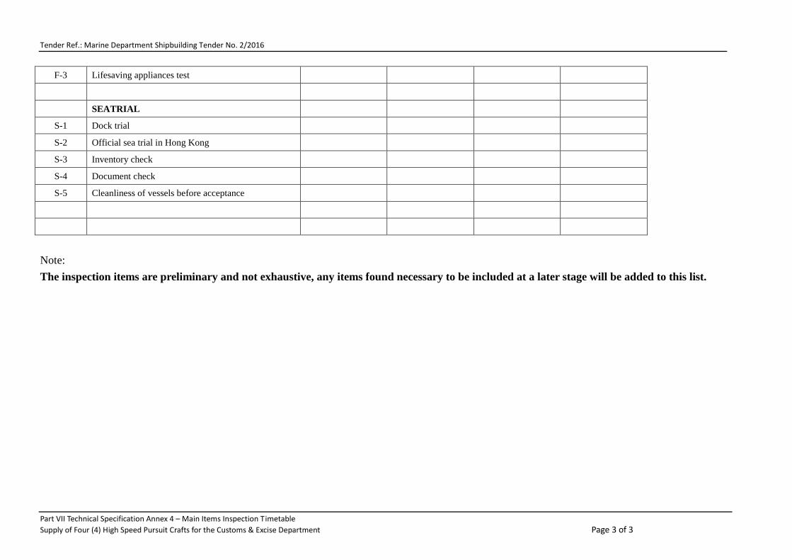
Tender Ref.: Marine Department Shipbuilding Tender No. 2/2016
F-3 Lifesaving appliances test
SEATRIAL
S-1 Dock trial
S-2 Official sea trial in Hong Kong
S-3 Inventory check
S-4 Document check
S-5 Cleanliness of vessels before acceptance
Note: The inspection items are preliminary and not exhaustive, any items found necessary to be included at a later stage will be added to this list.
Part VII Technical Specification Annex 4 – Main Items Inspection Timetable Supply of Four (4) High Speed Pursuit Crafts for the Customs & Excise Department Page 3 of 3

Tender Ref.: Marine Department Shipbuilding Tender No. 6/2016
Part VII - Annex 5 – Conditions for Official Sea Trial (carried out in Hong Kong)
1) Official Speed Trial
Conditions at Speed-Trial
1 Person on board 6 Persons (at 100 kg per person) 2 Fuel oil tanks 100% fuel tanks capacity 3 Fresh water tank 100% fuel tank capacity 4 Grey water tank 100% fuel tank capacity 5 Other Equipment 100 kg 6 Sea Conditions Sea state 2 : wave height 0.1 - 0.5 metres
2) Endurance and Performance Test
Conditions at Endurance and Performance Test
1 Person on board 6 Persons (at 100 kg per person) 2 Fuel oil tanks 100% fuel tanks capacity 3 Fresh water tank 100% fuel tank capacity 4 Grey water tank 100% fuel tank capacity 5 Other Equipment 100 kg 6 Sea Conditions Sea state 2 : wave height 0.1 - 0.5 metres
3) Manoeuvrability Test
3.1 Conditions at Forward Turning Circle Test
1 Person on board 6 Persons (at 100 kg per person) 2 Fuel oil tanks 100% fuel tanks capacity 3 Fresh water tank 100% fuel tank capacity 4 Grey water tank 100% fuel tank capacity 5 Other Equipment 100 kg 6 Sea Conditions Sea state 2 : wave height 0.1 - 0.5 metres
4) Crash Stop Test / Astern Running Test / Emergency Steering Test
Conditions at Crash Stop Test / Astern Running Test / Emergency Steering Test
1 Person on board 6 Persons (at 100 kg per person) 2 Fuel oil tanks 100% fuel tanks capacity 3 Fresh water tank 100% fuel tank capacity 4 Grey water tank 100% fuel tank capacity 5 Other Equipment 100 kg 6 Sea Conditions Sea state 2 : wave height 0.1 - 0.5 metres
Part VII – Technical Specifications - Annex 5 – Official Sea Trial Conditions Page 1 of 1 Supply of Four (4) High Speed Pursuit Crafts for the Customs & Excise Department

Tender Ref.: Marine Department Shipbuilding Tender No. 6/2016
Part VII - Annex 6 - Endurance and Performance Tests
Part VII – Technical Specifications Annex 6 - Endurance and Performance TestsSupply of Four (4) High Speed Pursuit Crafts for the Customs Excise Department Page 1 of 1
EngineSpeed(rpm)
VesselSpeed
(Knots)
Time(Start)
Time(Finish)
EngineOil
Pressure(Bar)
Engine(in) CWTemp.(oC)
Others Others
Remarks:
Fuel Consumption(litres/minutes)
Not less 15 minutes
Not less 15 minutes
Not less 15 minutes
Not less 15 minutes
PitchDiameterType
50% of RatedPower/rpm
Vessel's Name:
100 kg
100% full of Fuel Tank & Water Tank Other Equipment 100 kg
Waterjets:
Place of Test:
Sea state 2 : wave height 0.1 - 0.5 metres
Port Side Starboard Side Port Side Starboard Side
100% of RatedPower(EnduranceTest)
Not less 15 minutes
60% of RatedPower/rpm
Not less 30 minutes
80% of RatedPower/rpm
90% of RatedPower/rpm
70% of RatedPower/rpm
Maker
Not less 15 minutes
At MinimumCruising Speed
TypeSerial NumberRated Power
Direction of Rotation
Engine Load
__% of ratedPower
Rated Speed
Date of Test:
Vessel'sIdentification:
Person Onboard
Maker
6 (100 kg per person) Dummy Weight
Fuel(Diesel)/Water
Sea Conditions
Engines:
Conditions at Endurance and Performance Test

Tender Ref.: Marine Department Shipbuilding Tender No. 6/2016
Part VII - Annex 7 - As-fitted Drawings and Machinery/Equipment documents and information literature to be delivered to the Government after Delivery Acceptance
1. As-Fitted Drawings
1.1 Upon delivery of the Vessel, the Contractor shall deliver to the Government four (4) hard copies and two (2) soft-copies in pdf. and dwg. files of the following plans and drawings that contain the technical information of the Vessel and its machinery and equipment as they are when the Vessel is on the day accepted by the MD. These are termed the final version of the “As-Fitted” Plans and Drawings, and they must consist of the following ones as well as any other additional ones that may be required by GNC/MD during the design and construction of the Vessel and before the Vessel is accepted by the Government.
1.2 The As–Fitted Plans and Drawings shall be prepared by professional ship draughtsmen and they shall be prepared in a professional manner, scale, size and style normally required of in the ship design and construction business sector. All plans and drawings shall show and be clearly marked for the profile, plan, and section views of the layout, arrangement details, and construction details in a manner required by GNC officer.
1.2.1 General Arrangement Plan. 1.2.2 Lines plan and offsets data and table. 1.2.3 Stability information booklet and the inclining experiment report. 1.2.4 Hydrostatics, cross curves and intact and damage stability calculations for all ship loading conditions
specified in the Technical Specifications. 1.2.5 Vessel subdivision drawings and stability calculations. 1.2.6 Painting scheme of the whole Vessel. 1.2.7 Vessel draught marking diagram. 1.2.8 Detailed arrangement and layout plan of the deckhouse, accommodation, decks showing the
disposition of all main equipment, fittings and fixtures, furniture, doors, windows, hatches, manholes and access openings. The down-flooding openings (points) shall be clearing indicated on the drawings.
1.2.9 Equipment layout diagram. 1.2.10 Hull structural construction and hull scantlings drawings. 1.2.11 Hull shell and frames and the framings arrangement and construction plan. 1.2.12 Hull shell expansion plan. 1.2.13 Keel construction plan. 1.2.14 Steering system and steering arrangement diagrams. 1.2.15 Deckhouse and deck structural and construction plan. 1.2.16 Hull watertight bulkheads construction plan. 1.2.17 Deckhouse to deck connection detailed construction plan. 1.2.18 Deck edge and bulwark (if any) details and construction plan, including detailed structural
arrangement drawings of hull to deck connection. 1.2.19 Detailed cathodic corrosion prevention and arrangement plans and drawings for the Vessel
throughout. 1.2.20 Mast structural and construction plan and mast equipment arrangement plan. 1.2.21 Anchoring arrangement plan. 1.2.22 Piping diagrams for fuel oil, freshwater, lubrication oil, bilge, firefighting, scuppers and drains,
sewage system. 1.2.23 Fire prevention, fire control and firefighting system drawings. 1.2.24 Drawings of the main switchboard and all other switchboards and the electrical system. 1.2.25 Wheelhouse and cabin sound and heat insulation system diagram. 1.2.26 Main engines and generator sets arrangement and sitting plans and drawings of their fuel lines
and exhaust gas piping and arrangement. 1.2.27 Waterjets arrangement. 1.2.28 Vessel ventilation drawings for the wheelhouse, accommodation and other spaces. 1.2.29 Main fuel oil tank drawing and its associated piping and manifold(s), and filling, overflow
and ventilation system. 1.2.30 Freshwater tank and its associated piping arrangement. 1.2.31 Fuel oil tank(s) and its associated piping system
Part VII – Technical Specifications Annex 7 - As-fitted Drawings and Machinery/Equipment documents and information literature to be delivered to the Government after Delivery Acceptance Page 1 of 2 Supply of Four (4) High Speed Pursuit Crafts for the Customs & Excise Department

Tender Ref.: Marine Department Shipbuilding Tender No. 6/2016
1.2.32 Drawings for anchor, windlass and the anchoring system. 1.2.33 Lifesaving appliance arrangement plan and fire safety plan. 1.2.34 Distress signals, alarm systems, and internal/external communication arrangement and system plan. 1.2.35 Navigation lights, sound and signal diagrams. 1.2.36 Vessel overall lighting arrangement and light control plan. 1.2.37 Vessel alarm and signals, internal communication systems and public address systems plan. 1.2.38 General layout and arrangement drawing of the air-conditioning system. 1.2.39 Refrigerant piping layout drawing of the air-conditioning system. 1.2.40 Air-conditioning load calculation. The lists are not exhaustive, additional as fitted drawings may be added if required.
1.3 Documents to be provided by the Contractor
In not less than one month before the Delivery Acceptance of the Vessel, the Contractor shall provide for GNC acceptance a list of all documents to be provided.
When the Vessel is delivered to the Government Dockyard the Contractor shall deliver to the Government all the technical information, leaflets, literature, manuals and booklets etc. and whatsoever items that are necessary for the operation, handling, services, maintenance, spare parts, repairs and the technical understanding of any one of all the engines, machinery, motors, pumps, equipment, fittings and outfitting items of the Vessel.
Part VII – Technical Specifications Annex 7 - As-fitted Drawings and Machinery/Equipment documents and information literature to be delivered to the Government after Delivery Acceptance Page 2 of 2 Supply of Four (4) High Speed Pursuit Crafts for the Customs & Excise Department

Tender Ref.: Marine Department Shipbuilding Tender No. 6/2016
Part VII - Annex 8 – Definitions of Wave and Sea
Beaufort scale
number Description Wind speed
Wave height Sea conditions Land conditions
0 Calm
< 1 km/h (< 0.3 m/s) 0 m
Flat. Calm. Smoke rises vertically. < 1 mph < 1 knot
0 ft < 0.3 m/s
1 Light air
1.1–5.5 km/h (0.3–2 m/s) 0–0.2 m
Ripples without crests. Smoke drift indicates wind direction. Leaves and wind vanes are stationary.
1–3 mph
1–3 knot 0–1 ft
0.3–1.5 m/s
2 Light breeze
5.6–11 km/h (2–3 m/s) 0.2–0.5 m
Small wavelets. Crests of glassy appearance, not breaking
Wind felt on exposed skin. Leaves rustle. Wind vanes begin to move.
4–7 mph 4–6 knot
1–2 ft 1.6–3.4 m/s
3 Gentle breeze
12–19 km/h (3–5 m/s) 0.5–1 m
Large wavelets. Crests begin to break; scattered whitecaps
Leaves and small twigs constantly moving, light flags extended.
8–12 mph 7–10 knot
2–3.5 ft 3.5–5.4 m/s
4 Moderate breeze
20–28 km/h (6–8 m/s) 1–2 m
Small waves with breaking crests. Fairly frequent whitecaps.
Dust and loose paper raised. Small branches begin to move.
13–17 mph 11–16 knot
3.5–6 ft 5.5–7.9 m/s
5 Fresh breeze
29–38 km/h (8.1-10.6 m/s) 2–3 m Moderate waves of some length.
Many whitecaps. Small amounts of spray.
Branches of a moderate size move. Small trees in leaf begin to sway.
18–24 mph 17–21 knot
6–9 ft 8.0–10.7 m/s
6 Strong breeze
39–49 km/h (10.8-13.6 m/s) 3–4 m Long waves begin to form. White
foam crests are very frequent. Some airborne spray is present.
Large branches in motion. Whistling heard in overhead wires. Umbrella use becomes difficult. Empty plastic bins tip over.
25–30 mph
22–27 knot 9–13 ft
10.8–13.8 m/s
7
High wind, moderate gale, near gale
50–61 km/h (13.9-16.9 m/s) 4–5.5 m Sea heaps up. Some foam from
breaking waves is blown into streaks along wind direction. Moderate amounts of airborne spray.
Whole trees in motion. Effort needed to walk against the wind.
31–38 mph
28–33 knot 13–19 ft
13.9–17.1 m/s
8 Gale, fresh gale
62–74 km/h (17.2-20.6 m/s) 5.5–7.5 m Moderately high waves with
breaking crests forming spindrift. Well-marked streaks of foam are blown along wind direction. Considerable airborne spray.
Some twigs broken from trees. Cars veer on road. Progress on foot is seriously impeded.
39–46 mph
34–40 knot 18–25 ft
17.2–20.7 m/s
9 Strong gale
75–88 km/h (20.8-24.4 m/s) 7–10 m High waves whose crests
sometimes roll over. Dense foam is blown along wind direction. Large amounts of airborne spray may begin to reduce visibility.
Some branches break off trees, and some small trees blow over. Construction/temporary signs and barricades blow over.
47–54 mph
41–47 knot 23–32 ft
20.8–24.4 m/s
Part VII – Technical Specifications - Annex 8 – Definitions of Wave and Sea Page 1 of 2 Supply of Four (4) High Speed Pursuit Crafts for the Customs & Excise Department

Tender Ref.: Marine Department Shipbuilding Tender No. 6/2016
10 Storm, whole gale
89–102 km/h (24.7-28.3 m/s) 9–12.5 m
Very high waves with overhanging crests. Large patches of foam from wave crests give the sea a white appearance. Considerable tumbling of waves with heavy impact. Large amounts of airborne spray reduce visibility.
Trees are broken off or uprooted, saplings bent and deformed. Poorly attached asphalt shingles and shingles in poor condition peel off roofs.
55–63 mph
48–55 knot 29–41 ft
24.5–28.4 m/s
11 Violent storm
103–117 km/h (28.6-32.5 m/s) 11.5–16 m
Exceptionally high waves. Very large patches of foam, driven before the wind, cover much of the sea surface. Very large amounts of airborne spray severely reduce visibility.
Widespread damage to vegetation. Many roofing surfaces are damaged; asphalt tiles that have curled up and/or fractured due to age may break away completely.
64–73 mph
56–63 knot 37–52 ft
28.5–32.6 m/s
12 Hurricane
≥ 118 km/h (≥ 32.8 m/s) ≥ 14 m Huge waves. Sea is completely
white with foam and spray. Air is filled with driving spray, greatly reducing visibility.
Very widespread damage to vegetation. Some windows may break; mobile homes and poorly constructed sheds and barns are damaged. Debris and unsecured objects are hurled about.
≥ 74 mph
≥ 64 knot ≥ 46 ft
≥ 32.7 m/s
World Meteorological Organization (WMO) Sea State Code
Sea State Code Wave Height (meters) Characteristics
0 0 Calm (glassy)
1 0 to 0.1 Calm (rippled)
2 0.1 to 0.5 Smooth (wavelets)
3 0.5 to 1.25 Slight
4 1.25 to 2.5 Moderate
5 2.5 to 4 Rough
6 4 to 6 Very rough
7 6 to 9 High
8 9 to 14 Very high
9 Over 14 Phenomenal
Character of the Sea Swell 0. None
Low 1. Short or average 2. Long
Moderate 3. Short 4. Average 5. Long
Heavy 6. Short 7. Average 8. Long
9. Confused
Part VII – Technical Specifications - Annex 8 – Definitions of Wave and Sea Page 2 of 2 Supply of Four (4) High Speed Pursuit Crafts for the Customs & Excise Department

Tender Ref.: Marine Department Shipbuilding Tender No. 6/2016
Part VII - Annex 9 List of Government Dockyard Contractors
No. Name of Contractors Contact Telephone Fax No. Contact Person
1 Cheoy Lee Shipyards, Ltd. 89 & 91 Hing Wah Street West, Lai Chi Kok, Kowloon.
852 2307 6333 852 2307 5577 C Y CHEUNG
2
Chu Kong Group Shipyard Co. Ltd. Chu Kong Group Shipyard Building, 93 Hing Wah Street West, Lai Chi Kok, Kowloon.
852 2815 0333 852 2815 2188 CHAN Wai-mui
3
Discovery Bay Enterprises Ltd., Unit 101, Discovery Bay Office Centre, No. 2, Plaza Lane, Discovery Bay, Lantau Island, Hong Kong.
852 2436 4883 852 2987 5246 852 2914 0918 CHAN Kam-bue
4
Fat Kee Marine Repairing & Engineering Co. Ltd., P.O. BOX 78638, Mongkok Post Office, Kowloon, Hong Kong
852 9224 0044 852 2743 8866 852 2768 8811 SIU Chan-shing
5
Hop Kee Engineering Work Ltd. SHX-1321, 45 Ap Lei Chau Praya Road, Hong Kong.
852 2785 9221 852 9489 5684 852 2785 9236 LEE Wai-ngung
6
Kwong Sang Engineering Co. Ltd. Ground Floor, 13 Hop Kwan Street, Tai Kok Tsui, Kowloon, Hong Kong
852 2785 7879 852 2785 7550 852 9037 4890
852 2786 2510 CHAN Leung-kan
7 Leung Wan Kee Shipyard Ltd. Lot 11, Tam Kon Shan Road, Tsing Yi (N), New Territories, Hong Kong
852 2495 1103 852 9424 5112 852 2433 0119 KAN Kwok-biu
8
The Chans’ Shipyard Ltd. Lot 22-23 Tam Kon Shan Road, North Tsing Yi Island, New Teritories, Hong Kong
852 2744 9113 852 2310 8272 852 9053 1211
852 2744 9283 LAM Kwan-chung
9
The Hong Kong Shipyard Ltd. 98 Tam Kon Shan Road, Ngau Kok Wan, North Tsing Yi, New Teritories, Hong Kong
852 2436 7188 852 2436 2011 MA Chi-wai
10
Tung Hing Ship Builder & Engineering Works Ltd. Ground Floor, 9 Wai On Street, Tai Kok Tsui, Kowloon, Hong Kong
852 9195 8155 852 9196 0117 852 2307 2533 852 2307 1629
852 2307 2637 WONG Tung-lam, CHEUNG Sui-fan
11
Tung Wo Engineering Co. Ltd. Room 2705, 27th Floor, New Treasure Centre, 10 Ng Fong Street, San Po Kong, Kowloon, Hong Kong
852 2328 3363 852 2328 3989 LO Kee-sang
12
Wang Tak Engineering & Shipbuilding Co. Ltd. 3rd Floor, Wang Tak Building, 85 Hing Wah Street West, Lai Chi Kok, Kowloon, Hong Kong
852 2746 2888 852 6770 6578 852 2742 2726
852 2307 5500 W K LAM
13 Wing Yip Engineering Works Ltd. Lot 145, 64 Tam Kon Shan Road, Tsing Yi, New Territories, Hong Kong
852 2781 2626 852 9238 0502 852 9238 0505
852 2332 2511 Cynthia NGAI, NGAI Yee-ming
14 Woo Cheng Mechanical Engineering Factory Ltd. Ground Floor, 195 Tai Kok Tsui Road, Kowloon, Hong Kong
852 2744 4113 852 2307 6131 852 9016 4527
852 2744 4632 852 2310 4884 CHENG King-yin
15
Yiu Lian Dockyards Ltd. No. 1-7 Sai Tso Wan Road Tsing Yi Island, New Territories, Hong Kong
852 2436 7728 852 2436 7800
852 2436 0712 852 2436 0590 BILL Marcus NG
Part VII – Technical Specifications Annex 9 - List of Government Dockyard Contractors Page 1 of 1 Supply of Four (4) High Speed Pursuit Crafts for the Customs & Excise Department