partial stroke testing - automation technology. prins pressure transmitter. ... please note that...
TRANSCRIPT

Copyright © Yokogawa System Center Europe2010
A.F.M. Prins
Partial Stroke
Testing

Copyright © Yokogawa System Center Europe2010
• PST in a safety related system.
As a supplier we have a responsibility to our clients.
What do they want,
and what do they really need?
I like to explain the concept based on a simple example:
HIPPS
Partial Stroke Testing

Copyright © Yokogawa System Center Europe2010
HIPPS
L O G IC S O L V E R
SH U T O F F V A L V E S
M A N IF O L D
&
T R A N S M IT T E R S
• What is a HIPPS?
A HIPPS is a protection device.
It acts like a fuse;
if the current is too high, the fuse blows.
If the pressure is too high;
the valves close.
The system behind is safe!
HIPPS stands for High Integrity Pressure Protection System

Copyright © Yokogawa System Center Europe2010
A HIPPS is that something NEW?
HIPPS are used for more than 30 years.
And HIPPS are still used, all around the world.
In all kind of applications.

Copyright © Yokogawa System Center Europe2010
Why a HIPPS?
A HIPPS is, or can be a protection against…
�Human casualties
�Environmental damage
�Damage to your Investments
�Penalties due to emissions (no flaring policy)
�Too high investments….?

Copyright © Yokogawa System Center Europe2010
When Availability & Integrity Really Count

Copyright © Yokogawa System Center Europe2010
A.F.M. Prins
SAFETY

Copyright © Yokogawa System Center Europe2010
process risk
Residual
risk level
Risk inherent
in process
Tolerable
risk level
Risk reduction
Risk
Other ExternalSIS
Process

Copyright © Yokogawa System Center Europe2010
risk graph
� Extent of damage (S)� S1: Minor injury/damage
� S2: Serious injury, death of one person
� S3: Death to several persons
� S4: Catastrophic consequences
� Frequency of exposure (A)� A1: Seldom
� A2: Quite often to permanent
� Avoiding of hazard (G)� G1: Possible
� G2: Almost impossible
� Probability of event (W)� W1: High
� W2: Low
� W3: Very low
4 4
1
1
2
2
3
3
-
-
w3
S1
S2
S3
S4
A2
A2
A1
A1
G1
G1
G2
G2
1
1
2
2
3
3
-
w2
4
1
1
2
2
3
3
w1

Copyright © Yokogawa System Center Europe2010
requirements safety instrumented system
�From the risk graph a Target SIL for the SIS will result
�The target SIL indicates the maximum average Probability of failure on demand (PFD) the safety system may have
≥ 10-5 to < 10-4
≥ 10-4 to < 10-3
≥ 10-3 to < 10-2
≥ 10-2 to < 10-1
Average Probability offailure on demand
4
3
2
1
SafetyIntegrity
Level
0
SafetyAvailability
99.9 - 99.99%
99 - 99.9%
90 - 99%
> 99.99%
Risk ReductionFactor
1 000 - 10 000
100 - 1 000
10 - 100
> 10 000
(Control NA)

Copyright © Yokogawa System Center Europe2010
Industrial standards for safety
� IEC 61508 � Functional safety of electrical/electronic/programmable
electronic safety-related systems (E/E/PE)
� Can be applied to all electro-mechanical systems across a wide range of industries.
� IEC 61511� Functional safety / Safety Instrumented Systems for the
process industry
� Targeted at end users implementing SIS for the process industry, it has with more emphases towards
PROVEN IN USE
Copyright © Yokogawa System Center Europe2010
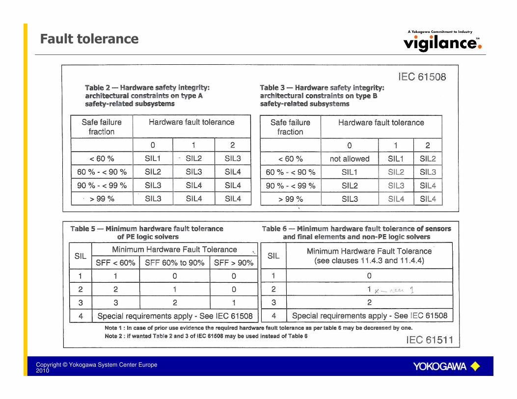
Fault tolerance

Copyright © Yokogawa System Center Europe2010
three most significant aspects of IEC 61508
��The Safety LifecycleThe Safety Lifecycle
��The The ““PipePipe--toto--PipePipe”” approachapproach
��The quantitative safety assessmentThe quantitative safety assessment

Copyright © Yokogawa System Center Europe2010
Required SIL
Time
1
SIL
2
3
PFD
10-1
10-2
10-3
10-4
10-5
Periodic proof test interval
T0 T1 T2 T3 T4

Copyright © Yokogawa System Center Europe2010
Safety Instrumented System
OOProtection logic
Process pipe
Sensors
Process pipe
Final elements
Safetyvalve
Logic solver
OutputInput
Transmitter
A
D
A
D
Pipe to pipe
AirVent.

Copyright © Yokogawa System Center Europe2010
Quantitative Assessment
�Total Loop
The safety requirements concern (as a minimum) a complete safety loop and are expressed in Safety Integrity Levels (SIL).
�PFD
The SIL levels correspond to the average Probability of failure on demand (PFD target) of a complete safety loop.
�Quantification
Calculations need to be performed to show that a specific safety loop meets its required SIL level.

Copyright © Yokogawa System Center Europe2010
Probabilities / Safety Integrity Level
Safety Interlocks
Safety InterlocksTR
TR
TRTR
TRTR
Safety valve
Air
Vent
Pfd loop =
Pfd sensors + Pfd logic solver + Pfd final elements
SIL = Pfd target

Copyright © Yokogawa System Center Europe2010
A.F.M. Prins
HIPPS Functionality

Copyright © Yokogawa System Center Europe2010
Process parameter range
Process value
Trip level
Mechanical safety level
High level
High alarm level
Low level
Time
Normal Condition
Alarm Condition
Unsafe Condition
Operator takes action
ESD action
Boom?
Control
Safety

Copyright © Yokogawa System Center Europe2010
What is a HIPPS
�HIPPS, the last line of defenseHIPPS
ESD
PSD
DCS
4-20 mA
4-20 mA Prog.
Tripamp
AI-917
Prog.
Tripamp
AI-917
4-20 mA
Input
DI-511
8-channel
Inputs for:
Reset, valve test
Proximity switches,
other
2oo3
4 * 5 W Solenoid driver
Prog.
Tripamp
AI-917
Prog.
Tripamp
AI-917
Alarm
Logic
2oo3 manifold
HIPPS valve HIPPS valve
HIPPS
solenoid
local reset
HIPPS
solenoid
local reset
HIPPS
solenoid
local reset
HIPPS
solenoid
local reset
P
T
P
T
P
T
Communication to PLC/DCS/SCADA
Modbus
Prog.
Tripamp
AI-917Analog value discrepancy
HIPPS
Logic
Solenoid
Driver
Output
FO-529
ProSafe COM / Sequent of event / Alarm handling
Status information / Analogue values
Modbus RS-232, RS-485
DO-523
Lamp
driver
MC-562
AI repeat
Flow direction
Local SOE
recorder

Copyright © Yokogawa System Center Europe2010
A.F.M. Prins
Pressure Transmitter

Copyright © Yokogawa System Center Europe2010
TÜV SIL 2 Approved

Copyright © Yokogawa System Center Europe2010
Measuring
�Transmitters; certified for use in a SIL 2 loop…
�3 transmitters meeting SIL 3 … SIL 4
voting 2oo3 or 1oo2.
�What is the influence of a common fault...

Copyright © Yokogawa System Center Europe2010
A.F.M. Prins
MANIFOLD

Copyright © Yokogawa System Center Europe2010
Triple Manifold

Copyright © Yokogawa System Center Europe2010
Locking Manifolds
�Key controlled procedures in single manifolds.
� Double block and bleed
� Mechanical interlock
� Detection
� SIL approval

Copyright © Yokogawa System Center Europe2010
A.F.M. Prins
LOGIC SOLVER

Copyright © Yokogawa System Center Europe2010
MagLog 3
1960
Innovation and Continuity
MagLog 14
1970MagLog 24
1990ProSafe-SLS
1997
A PROVEN CONCEPT
COMFORTABLE IN SAFETY

Copyright © Yokogawa System Center Europe2010
Magnetic CoreMagnetic Core
Anticlockwise magnetisation Clockwise magnetisation
B B
H H
Rectangular Hysteresis loop Flat Hysteresis loop
Magnetic particle orientation

Copyright © Yokogawa System Center Europe2010
& Z
Y
X
“Write”
“Read”
output
““ANDAND”” FunctionFunction

Copyright © Yokogawa System Center Europe2010
AND functionAND function
X
Z
Y
+20V0A
B-pulse(Clock)
+20V0
A
A-pulse(Clock)
B+20V0
A
B
& Z
Y
XLogical 0
Logical 1
A

Copyright © Yokogawa System Center Europe2010
A.F.M. Prins
HIPPS Valves

Copyright © Yokogawa System Center Europe2010
Control of the Valves
�Solenoids
�Actuator
�Valve

Copyright © Yokogawa System Center Europe2010

Copyright © Yokogawa System Center Europe2010
HIPPS Valves
�Testing of a Valve
�Partial stroke testing
What are we testing?
What do we claim?
Is that safe?
Please note that Partial Stroke test can never replace
a full stroke test!!!
�Full stroke test

Copyright © Yokogawa System Center Europe2010
HIPPS Philosophy
Isolate the source of the problem rather than releasing to
the atmosphere.
To do so;
High reliable equipment is required!
A failure in your HIPPS will result in
damage of equipment or endanger the
safety of personnel.
Copyright © Yokogawa System Center Europe2010
A.F.M. Prins
CERTIFICATION

Copyright © Yokogawa System Center Europe2010
Wherever you need safety expertise,Wherever you need safety expertise,
whether in bid phase, whether in bid phase,
early project involvement, early project involvement,
or in project execution or in project execution ……
contact acontact a
Safety Assurance & ConsultancySafety Assurance & Consultancy
safety consultancy

Copyright © Yokogawa System Center Europe2010
A.F.M. Prins
Conclusion

Copyright © Yokogawa System Center Europe2010
Conclusion on PST

Copyright © Yokogawa System Center Europe2010
Conclusion
In general you can say:
A well designed HIPPS,
not only saves money but
“makes the world
a little safer after all”.

Copyright © Yokogawa System Center Europe2010
Thank you for your attention.
Commitment means building the future to last.