particle motion in stokes flow near a plane fluid-fluid...
TRANSCRIPT
J . Fluid Mech. (1983), vol. 136, p p . 393421
Printed in Great Britain 393
Particle motion in Stokes flow near a plane fluid-fluid interface. Part 1. Slender body in a
quiescent fluid
By SEUNG-MAN YANG AND L. GARY LEAL Department of Chemical Engineering, California Institute of Technology,
Pasadena, California 91 125
(Received 19 October 1982 and in revised form 19 July 1983)
The present study examines the motion of a slender body in the presence of a plane fluid-fluid interface with an arbitrary viscosity ratio. The fluids are assumed to be at rest at infinity, and the particle is assumed to have an arbitrary orientation relative to the interface. The method of analysis is slender-body theory for Stokes flow using the fundamental solutions for singularities (i.e. Stokeslets and potential doublets) near a flat interface. We consider translation and rotation, each in three mutually orthogonal directions, thus determining the components of the hydrodynamic resistance tensors which relate the total hydrodynamic force and torque on the particle to its translational and angular velocities for a completely arbitrary translational and angular motion. To illustrate the application of these basic results, we calculate trajectories for a freely rotating particle under the action of an applied force either normal or parallel to a flat interface, which are relevant to particle sedimentation near a flat interface or to the processes of particle capture via drop or bubble flotation.
1. Introduction When a small particle moves in the vicinity of a boundary, its motion will be
affected owing to hydrodynamic wall effects. We have previously considered the motion of a spherical particle in creeping motion near a fluid-fluid interface (Lee, Chadwick & Leal 1979; Lee & Leal 1980, 1982; Berdan & Leal 1982). The present paper is the first of a series in which we extend this work to consider the creeping motion of slender rod-like bodies in the same circumstances. A number of different problems are of potential interest, corresponding to various types of application. For example, the translation and rotation of a fibre-like particle in a quiescent fluid system is relevant to sedimentation phenomena, and to theories of Brownian motion for particles near a fluid-fluid interface. Particle motions in more general flow fields such as pure straining flow or simple shear flow are relevant in suspension mechanics, and to some aspects of the process of particle capture at the surface of a large bubble or drop (cf. Goren & O’Neill 1971).
In this present work, we use the fundamental solutions of Lee et al. (1979) in combination with slender-body theory for Stokes flow (cf. Batchelor 1970; Cox 1970, 1971; Johnson & Wu 1979; Keller & Rubinow 1976; Johnson 1980; among others) to study the translation and rotation of an arbitrarily oriented, straight slender body through a quiescent fluid near a$at fluid-fluid interface. The resulting solutions are valid, as a zeroth-order approximation, under any conditions where the interface
394 S.-M. Yang and L. G . Leal
deformation remains small (Lee et al. 1979). On physical grounds, this occurs when either the separation distance between the particle and the interface is much larger than the characteristic length of the particle, or when either the surface tension or the density difference between the two fluids is very large.
Recently, Fulford & Blake (1983) have considered the same general problem considered here, but only for translation with the body oriented either parallel or normal to the interface. Fulford & Blake’s analysis yields the hydrodynamic force for these two particular orientations, as well as the induced torque due to the interface, but cannot be used to calculate the instantaneous angular velocity of the particle (as claimed by Fulford & Blake) without solving for particle rotation in a quiescent fluid to determine the relationship between torque and angular velocity in the presence of the interface. Furthermore, the Fulford & Blake solutions cannot describe the motion of an arbitrarily oriented body, and thus cannot, for example, provide trajectories for particle motion under the action of a force if the particle is free to rotate.
In the present paper we consider translation and rotation, each in three mutually orthogonal directions. The solutions of these six fundamental problems, each with an arbitrary orientation of the particle, provide all of the components of the hydrodynamic resistance tensors which relate the hydrodynamic force and torque on the particle to its translational and angular velocities, for arbitrary particle motions in a quiescent fluid. These fundamental solutions are then applied, for illustrative purposes, t o calculate particle trajectories for ‘ sedimentation ’ of a freely rotating particle due to an applied force which acts either normal or parallel to a flat interface.
2. Basic equations We begin by considering the governing differential equations and boundary
conditions for a rigid, non-axisymmetric, straight slender body which moves, with translational velocity U and angular velocity D near an interface which separates two immiscible Newtonian fluids. The fluids will be denoted as I and 11, with the body wholly immersed in the fluid 11. It is assumed that the relevant Reynolds number
u1 ( 5 2 1 2 ) R e = - or-
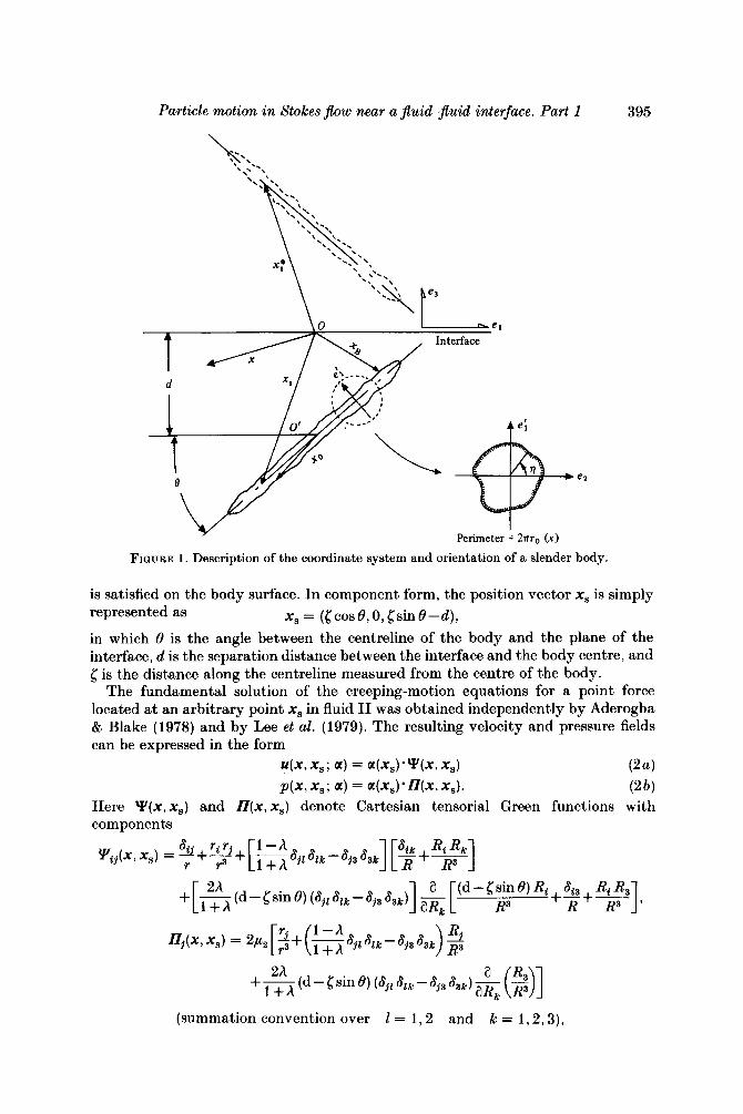
v.2 \ v 2 1 is sufficiently small (Re 3 1 ) that the quasi-steady creeping-motion approximation is applicable, where v p represents the kinematic viscosity of the fluid I1 and 1 is the half-length of the body. As the body moves it induces a disturbance motion in the two fluids, and in slender-body theory the associated flow field at low Reynolds number is investigated by examining a nearly equivalent problem in which the body is replaced by a line distribution of Stokeslets along the axis of the body. A slender body with an arbitrary orientation is depicted in figure 1. We adopt a coordinate system in which the x1 axis coincides with the projection of the body centreline onto the interface, which is itself located at x3 = 0. Stokeslets are distributed over the portion - 1 < x < 1 of the body axis, with the magnitude of the point force at any position x, on this line denoted as
fs(x,) = 87cP2 a(x,) W-XX,) ,
in which 6(x) is the three-dimensional Dirac delta function. The vector density (or weighting) function a@,) must be chosen as a function of position along the particle axis so that the no-slip boundary condition
u2 = u+nxx, (1)
Particle motion in Stokes flow near a fluid-fluid interface. Part 1 395
-b
Perimeter = 2 ~ ~ 7 0 (x)
FIQURE 1. Description of the coordinate system and orientation of a slender body.
is satisfied on the body surface. In component form, the position vector x, is simply represented as x, = (gcosO,O,[sinO-d),
in which 0 is the angle between the centreline of the body and the plane of the interface, d is the separation distance between the interface and the body centre, and 5 is the distance along the centreline measured from the centre of the body.
The fundamental solution of the creeping-motion equations for a point force located at an arbitrary point x, in fluid I1 was obtained independently by Aderogba & Blake (1978) and by Lee et al. (1979). The resulting velocity and pressure fields can be expressed in the form
$x,x,; a) = a(x , ) -Y (x , x,) p ( x , x,; a) = a(x , ) .n (x , x,).
P a ) (2b)
Here Y(x, x,) and D(x, x,) denote Cartesian tensorial Green functions with components
(summation convention over I = 1 , 2 and k = 1,2 ,3) ,
396 S.-M. Yang and L. G . Leal
where r = x-x,, R = x-x:, r = Irl, R = IRI, h = ,u1/,u2, and x,* denotes the reflec- tion point of x, in the fluid I. Thus, for a line distribution of Stokeslets with the line density a@,) the resulting fluid velocity u(x ) and pressure p ( x ) at a point x in the
The velocity and pressure fields defined by these equations automatically satisfy the conditions of zero normal velocity, continuity of tangential velocity and continuity of the shear stress at the fluid-fluid interface, as well as the condition of vanishing velocity in the far field (note that the Green functions Y(x , x,) and H(x, x,) are O ( l / r ) and O ( l / r 2 ) for r 9 1). All that remains is to satisfy the no-slip boundary condition ( I ) , according to which the fluid velocity must be U+B x X, a t the body surface. Thus, the unknown function a(x,) representing the line density of Stokeslet strengths must be determined so that the disturbance velocity given by (3a) is at least approximately equal to U+B x x, at all points of the body surface. It should be noted that, in general, a line distribution of Stokeslets alone will not be sufficient to satisfy the no-slip boundary condition at all levels of approximation for all points on a body surface. Higher-order singularities (e.g. potential dipoles) are also generally needed, even in the case of an axisymmetric body. However, when the body is slender, the boundary condition a t the body surface can always be satisfied to an order of approximation, O(s) , where s = [In (2Z/R0)]-l, without explicit introduction of the higher-order singularities. Furthermore, the total hydrodynamic force or torque acting on the body can be determined from the Stokeslet distribution alone as pointed out previously by Batchelor (1970).
A point on the body surface can be expressed in terms of cylindrical polar coordinates ( r , 7, z). It is assumed that the cross-section of the body has an effective radius yo(%) which is a function of distance x along the body centreline. The maximum value of ro(x) is denoted as R,. The cross-sectional shape need not be circular, provided only that we choose ro ( z ) such that the perimeter is equal to 2nr,(x) (Batchelor 1970). A t the body surface,
x = xB = (xcos0-rOsinpsin0, r,cosq, zs in0-d+rosin~cos8) .
Applying the no-slip boundary condition at the body surface to (3a) yields a Fredholm integral equation of the first kind for the unknown Stokeslet distribution a@,), i.e.
U + 52 x x, = 1, a(x,).Y(x,, x,) dC. (4)
The theoretical analysis that follows will be based on the assumption that both Roll and R,/(d - 1 sin 0 ) ( > R,/d) are small. The first assumption is a slenderness criterion, while the second implies that the slender body is not closer than a few radii from the interface. In view of the linearity of the problem, the translational and rotational components of the particle motion can be considered separately, and we begin with translational motions of an arbitrarily oriented body parallel and perpendicular to the interface.
Particle motion in Stokes flow near a fluid-Jluid interface. Part 1 397
3. Fundamental solutions for translation of a slender body near a flat fluid interface
3.1. Motion parallel to the interface along the x1 axis
Let us then consider an arbitrarily oriented slender body which is moving with a translational velocity Ulel in the direction of the x1 axis through fluid 11. In this case, in order to satisfy the no-slip boundary conditions, it is necessary to employ distributions of Stokeslets oriented in both the el and e3 directions. By substituting
a(x,) = (al(c), O , 0 1 3 ( < ) ) 7 u(xB) = (ul, O , O ) into (4) we obtain three simultaneous Fredholm integral equations of the form
1
c'i = [a,(<) ' yij(xB3 <)I d<
( i = 1,2,3, summation convention over j = 1,2,3) (5 )
These integral equations cannot be solved exactly (except by numerical methods), but can be solved approximately by means of an asymptotic expansion for small Roll and R,/d. After much algebra, expanding ( 5 ) to O(R& Ro/d), we obtain
(xl component)
1 Ul = al(x) 2 -+S(x) (cos2 8+ 1)-2 cos2 8 + 2 sin2 7 sin28+&(x; A, 8, d) [ ( t : ) 1 -sin2q sin2 28+&(x; A, 8, d )
( x 2 component)
( x 3 component)
1 -sin27sin28+R(x;A,8,d)
1 (1 + sin2 69-2 sin2 7 cos2 8-2 sin2 8+ W ( x ; A, 8, d)
E
+[-z [aj(!3-aj(x)1 y3j(xB,5)d5+0e>$), (6c)
where
(See Appendix for specific formulae for P ( z ; A, 8, d ) , &(z; A, 8, d), R(x; A, 8, d ) and W(x;h ,B,d) . t ) The primary small quantity ~ ( 4 1 ) which will be used in the
~ subsequent analysis represents a slenderness parameter, and S(x) is a shape function of the body (specified once ro(x) is given).
t The Appendix is not reproduced here. A copy may be obtained on request from either the authors or the Editor of the Journal.
398 S.-M. Yang and L. G. Leal
I n an analysis of the similar integral equations for the infinite-fluid case, Tuck (1964), Tillet (1970) and Batchelor (1970) suggested an expansion of a(z) in powers
(7) of c ,
as a straightforward way to obtain an approximate solution of the integral equations (6a-c) for the unknown function a(.). It may be worth pointing out that solving the integral equation ( 5 ) using an expansion such as (7 ) in powers of c requires retention of an infinite number of terms to ensure that the associated error is no larger than the error O(Ro/ l ) that is inherent in (6a-c). I n fact, we determine the first two terms in the expansion (7) satisfying the boundary condition ( 1 ) up to O(c2) , following in the spirit of Batchelor (1970), Cox (1970) and others who adopted the same level of approximation to calculate such parameters as the hydrodynamic force and torque for slender-body motion in an unbounded fluid.
The sin27 terms (O(c2) ) which appear in (6a , c ) are indicative of the fact that higher-order singularities are necessary if the boundary conditions are to be satisfied a t O(c2) . Obviously, with the no-slip condition (cf. ( 5 ) ) the fluid velocity a t the body surface is required to be independent of 7. To remove the 7-dependence associated with the Stokeslet distribution, a line distribution of potential dipoles must be superposed on the line distribution of Stokeslets a t O(e2) . The fundamental solution for a potential dipole located near a plane interface has been obtained by Lee et al. (1979). The required line distribution of potential dipoles can be shown to be related to a(.) by the relationship
It remains only to determine the distribution function a(x). After adding the fundamental solution for a line distribution of potential dipoles
with line density given by (8) to the Stokeslet solution in the form (6), and utilizing the expansion (7 ) , we find immediately that
q x ) = +(x) + e2aj(x) + c3a3x) + . . . ,
I(.) = - t [ r 3 4 4x11. (8)
+ A ( ~ ; A , 8, d ) + 0 ( € 3 ) , I1 3 sin2 8- 1 [e-;[2S(x)+ 1 + sin2 8
(sin2 8 + 1 ) Ul 4 %(X) =
sin28 '' [c-f [2S(z) + 3+E(x; A , 8, d)] +O(c3) . a3(x) = - 8 1
Specific formulae for A ( x ; A, 8, d ) and E ( x ; A, 8, d) are given in the Appendix. Russel et a.1. (1977) have carried out an analysis of the interaction between a cylindrical slender body and a single rigid plane wall. The leading-order terms in (9a, b) for h -too are identical with their asymptotic solutions since the interface (or rigid-wall) effects are of order c2.
It may be noted that the shape function S(x) becomes singular a t the ends of the body for all but ellipsoidal shapes where S(x) = 0, and the solution for the Stokeslet distribution (i.e. (9a, b ) ) is not valid a t the body ends. However, i t can be shown that the singular behaviour of S(x ) makes no contribution to the total hydrodynamic force
and torque exerted on the slender body (since lim (xn.lnx)+Ofor any positive x+o+
integer n), and we make no attempt to improve on the solution near the ends of the body, though methods to do so have been known for some time (Tuck 1964).
The total hydrodynamic force F associated with translation in the el direction can be calculated simply by integrating the line density of the Stokeslet distribution a(x) with respect to x from -1 to 1,
rl F = - 8np2 J a(x) dr.
-1
Particle motion in Stokes $flow near a JEuid-jIuid interface. Part 1 399
The hydrodynamic torque T with respect to the centre of the body can also be obtained from the Stokeslet distribution, and is equal to
T = - Snp, I, xo x a(x) dx.
For a circular cylindrical slender body ( r o ( x ) = Ro), the shape function is S(x ) = i l n [ l - ( ~ / 1 ) ~ ] , and the total hydrodynamic force and torque can be obtained by direct integration of (10) and (11). The results are
+ 1 S A (X ; A, 8, d ) dx)] 3 sin2 8- 1 2(1 +sin28) 41 -1
Fl =-4np2UlZ(sin28+1)e
T, = 2np2 G , s i n H ~ ~ ~ ~ xH(x;A,8,d)dx+O(s3), (13) -1
where H ( x ; A, 8, d ) is defined by
H ( x ; A, 8, d ) = g( 1 + sin2 8) A ( x ; A, 8, d ) + 4 cos2 8 E(x ; A , 8, d ) .
For an ellipsoidal body, for which the shape function is S(x ) = 0, the total hydrody- namic force can also be obtained by substituting j L l S ( x ) dx = 0 in place of 21(ln 2 - 1) in (12a, b) . However, the hydrodynamic torque remains the same since jLl xS(x)dx vanishes for all even functions of S(x) .
When the slender body is oriented perpendicular to the interface (19 = go"), (6a , c ) must be modified since sec 8 is singular. In this case, the resulting expression for the total force and induced torque on a circular cylindrical slender body (i.e. the force and torque corresponding to the translational motion U, el) is
Fl = -8np2UlZ s -s2 ln2--+- a(x;A,d)dx + O ( s 3 ) , [ ( 2 41 ' S - E 11 xa(x;A,d)dx+O(e3),
where, again, the function a ( z ; A, d ) is given in the Appendix. The special cases 8 = 0" or 90" were considered by Fulford & Blake (1983), and the present results (12a), (13), (14) and (15) for 8 = 0" and 90" reduce precisely to their results for Fl and T, through terms O(s3) . The instantaneous angular velocities calculated by Fulford & Blake are wrong, however. Although the analysis above yields T, as a function of U,, the relationship between T, and Q2 must still be determined, and this was not done by Fulford & Blake (1983), who instead used the relationship for rotation in an unbounded fluid.
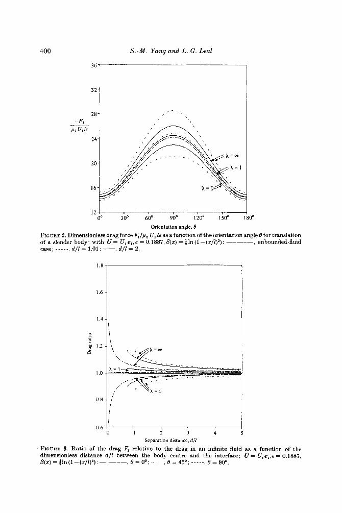
The effects of hydrodynamic interaction between the particle and the interface are contained in the complicated functions A ( x ; A, 8, d ) , E ( x ; A, 8, d ) , H ( x ; A, 8, d ) and a ( x ; A , d ) of (12)-(15). Thus, in order to illustrate the qualitative nature of these effects, the force components Fl and F3, and the torque T, are plotted in figures 2, 4 and 5 as functions of the orientation angle 0 for s = 0.1887 (which corresponds to Ro/Z = 0.01), and two values of particle position, d / l = 1.01 and 2. For each value of d/Z, we include three values of the viscosity ratio, A = 0, 1 and 03. Also shown in
400
1.6 -
1.43
S.-M. Yang and L. G . Leal
-1 32
12 O0 30" 60" 90" 120" 1.50"
Orientation angle, B
10"
FIGURE 2. Dimensionless drag force Fl/p2 Ul Is M a function of the orientation angle 8 for translation of a slender body; with U = U,e,,e = 0.1887,S(r) = i ln ( 1 -(z/Qa): unbounded-fluid case; - - - - - , d / l = 1.01; -, d / l = 2.
1.8
, 0.6 0
Separation distance, d/l
FIQURE 3. Ratio of the drag Fl relative to the drag in an infinite fluid as a function of the dimensionless distance d / l between the body centre and the interface; U = U,e,,e = 0.1887, S(r) = gln (1 - (r/Z)2) : -----, 0 = 00; -, 8 = 450; ___--, = goo.
Particle motion in Stokes $ow near a fluid-$uid interface. Part 1 40 1
8 I
-12 ; O0 30" 60" 90' 120" 150" 80°
Orientation angle, 0
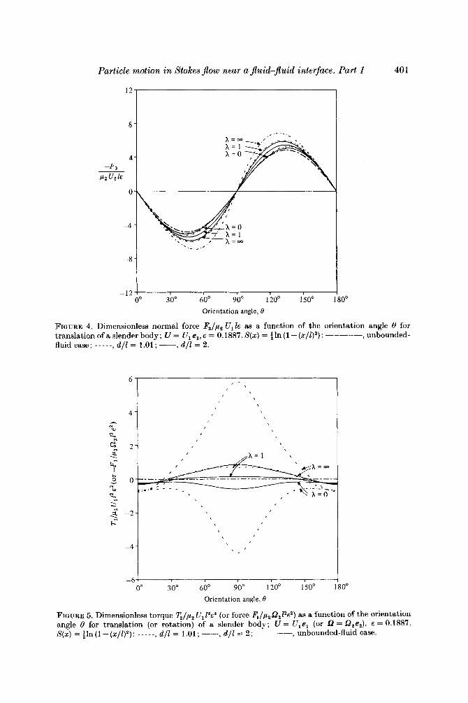
FIGURE 4. Dimensionless normal force F3/p2 u,k as a function of the orientation angle 0 for translation of a slender body; U = U , el, E = 0.1887, S(z) = ;In (1 - ( ~ / l ) ~ ) : -----, unbounded- fluid case; -----, d / l = 1.01; -, d / l = 2.
-11 . '
1
90" 120' 1.50' 1 -6-
O0 30" 60'
Orientation angle, 0
30°
FIGURE 5. Dimensionless torque !l!Jp2 U , 12e2 (or force F1/p252,l2e2) as a function of the orientation angle 0 for translation (or rotation) of a slender body; U = Ulel (or a = Q,e,), E = 0.1887, S(z) = gln (1 - (z/1)2) : - - - - -, d / l = 1.01 ; -, d / l = 2; -----, unbounded-fluid case.
402 S.-M. Yang and L. G . Leal
each case is the corresponding result for motion in an unbounded fluid. The qualitative dependence of the drag force Fl on the orientation angle 8 is unchanged from the unbounded case by hydrodynamic interactions with the interface. However, owing to the presence of the interface, the magnitude of Fl is either increased or decreased for any arbitrary 8, depending upon the viscosity ratio A, and this effect is a strong function of the particle position relative to the interface. In particular, the ratio of the drag force Fl to the drag in an infinite fluid for 8 = Oo, 45' and 90°, and E = 0.1887, is seen in figure 3 to become a stronger function of h as d / l decreases, except for the case of 8 = Oo and h = 1 . The existence of a critical value of h separating cases in which the drag is either increased or decreased due to the presence of the interface was noted for the special cases 8 = 0' and 90° by Fulford & Blake (1983), and is also similar to the results obtained by Lee et al. (1979) for translation of a sphere parallel to a flat fluid interface. The magnitude of the effect of the interface on particle drag is, however, considerably larger for a sphere of radius a , with its centre at a distance d / a from the interface than for a cylindrical slender body of length 21 with its centre an equal distance d / l (= d / a ) away.
The general features of the force component F3 normal to the direction of motion, as a function of 8, are again quite similar to those for the case of the same particle moving in an unbounded fluid. The fact that F3 is non-zero means that a motion in the '1'-direction cannot be sustained (say by a force in the l-direction) without simultaneous application of a force - F3 to the particle by some external means. In the absence of an applied force, -Fa, a positive force on the body in the ' 1 '-direction will yield a component of motion toward the interface for Oo < B < 90° (see figure 1 ) or away from the interface for 90' < 0 < 180O. The normal force F3 is increased in magnitude for all h by the presence of the interface. It may also be noted that the fractional increase in the hydrodynamic force for a given d / l and h is much larger for F3 than for Fl. Thus, the normal force associated with translation at an oblique angle to the symmetry axis is more sensitive to the presence of the interface than the drag.
The induced hydrodynamic torque T,, given by (13) and (15), is due solely to the presence of the interface (i.e. T,+O as d/l+co). It is evident, since T, =k 0, that a slender body cannot sustain a translational motion U = Ul el without simultaneously rotating unless a torque -T, is applied to the body by some external means. Thus, a freely suspended slender body (i.e. one with T = 0) will rotate with a sense (i.e. + or - ) which depends on A and on the orientation and position of the body relative to the interface (i.e. 8 and d) . This rotation can be viewed as a consequence of the gradient in the induced Stokeslet strength along the body axis due to the presence of the interface, and is also characteristic of spheres and rigid bodies of other shapes.
The translation of a rigid sphere parallel to a flat interface was analysed in detail by Lee & Leal (1980). In that case, the sense of rotation was determined, for a given dla, solely by the viscosity ratio A. Here it can be seen from figure 5 that the orientation angle plays a critical role, in addition to A and d l l , in determining the direction of rotation. Indeed, for h = 1 and co, rotation in either direction is possible depending on 8. The angle between 90' and 180° (or between -90° and Oo) where T, = 0 represents a stable equilibrium orientation for each particular value of d / l that is illustrated in figure 5. It should be noted, however, that d / l will increase with time for 90' < 8 < 180° unless a force is applied to the particle in the direction normal to the interface. For h = 0, on the other hand, a slender body with its centre at d / l = 1.01 or 2 will rotate in the clockwise direction for all 8 so that its leading edge turns away from the interface. In figure 6 the induced torque is plotted versus the
Particle motion in Stokes Jlouj near a Jluid-Jluid interface. Part 1 403
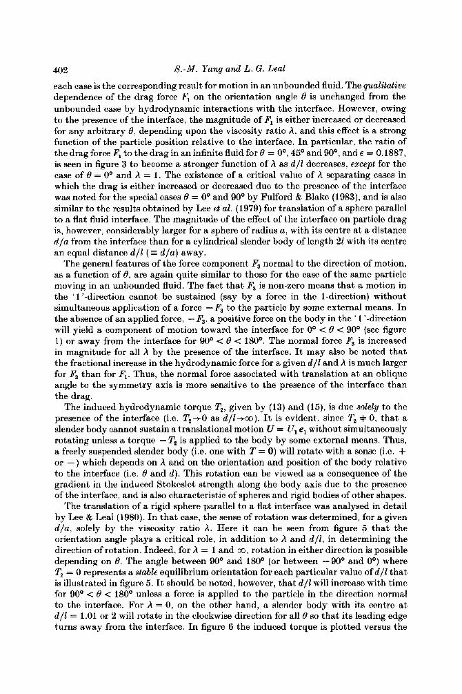
distance between the body centre and the interface for 0 = Oo, 45O and 90°, and h = 0, 1 and co. It can be noted that the magnitude of the torque increases rapidly as d l l decreases for 8 = 45O and 90°, whereas there exists a critical relative distance d l t at which the magnitude of the torque has a maximum value for 8 = 0'. Although it is tempting to conclude from figure 6 that the direction of induced rotation is independent of d l l (thus depending only on the viscosity ratio h and the orientation angle e), it is dangerous to draw such general conclusions from calculated results for only three values of h and three values of 8. Indeed, in the case of a rigid sphere near an interface, Lee & Leal ,( 1980) carried out a more detailed examination of the sense of the induced torque and showed, in that case, that there exists a critical distance beyond which the direction of rotation changes for any h in the range 6 < h < 00.
This change in direction with d would not have been evident at all for h = 0, 1 or 00, the three values considered in figure 6.
3.2. Motion parallel to the interface along the x2 axis
Let us now turn to the case of a slender body of arbitrary orientation translating parallel to an infinite plane interface along the x2 axis. In this case, the no-slip boundary condition on the body surface is u(xB) = U2e2. By the same approach outlined in 53.1, we have developed a relationship between the velocity U2e2 of the body and the point-force density a2(x) :
1
+ [a2(6)-a2(x)] Y2,(xB,6)d6 1 I, +0(+,2). (16)
FIQURE 6. Dimensionless torque ~ / p z U l 1 2 e 2 (or force F,/p,0212e2) as a function of the dimensionless distance d / l between the body centre and the interface; U = Ulel (or f2 = Q2e,),e = 0.1887,S(s) = ~ 1 n ( l - ( s / l ) 2 ) : -----, 0 = 0'; -, 6 = 45'; -----, 8 = 90'.
404 S.-M. Yang and L. G. Leal
_ _ _ _ _ _ _ _ _ _ - - - - - - -
24 7 I 22 --.:"1
- _ _ -
20 90' 120" 1.50" 180" 0" 30" 60'
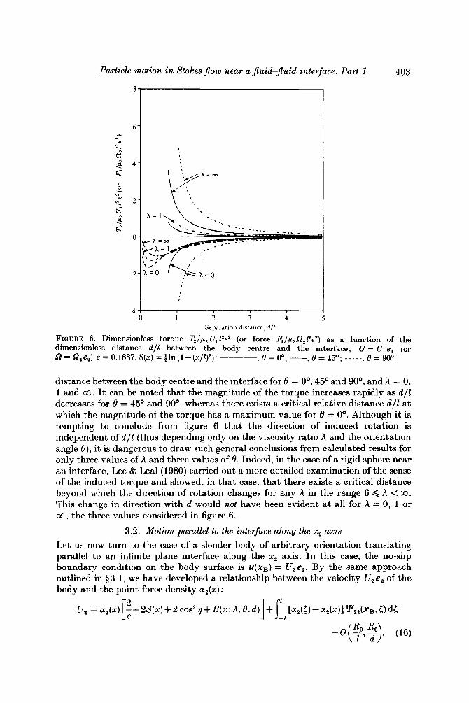
Orientation angle, 0 FIQURE 7. Dimensionless drag force F2/p2 U, 16 as a function of the orientation angle 0 for translation of a slender body; U = U,e , ,e = 0.1887,S(z) = i ln(l-(x/l)'): ----- , unbounded-fluid case ; _ _ _ _ _ , d / l = 1.01 ; -, d / l = 2.
In order to remove the 7-dependence of the fluid velocity associated with the Stokeslet distribution a t O(e2) , we again need an additional line distribution of potential dipoles with a density /?,(x) = -+$(x) or2(x). Then an asymptotic expansion of (16) together with the potential dipole distribution results in the following expression for a 2 ( x ) :
(17) CC,(X) = 4 U 2 [ ~ - 9 ' ( 2 X ( ~ ) + 1 +B(x;A, O,d))]+0(e3).
The hydrodynamic force and torque exerted on a circular cylindrical slender body are thus
F, = -8xp2 U,ls (18)
TI = -2xp2 u,sinOeZJ' xB(x;A,0,d)dx+0(e3), (19a) -1
1
= 2xp2 u,cosOe2 xB(x; A, 0 , d) dx+ 0 ( e 3 ) . I, The force and induced torque for the special case of a body oriented perpendicular to the interface must be calculated separately, but i t is obvious from symmetry considerations that the results are exactly those already given by (14) and (15) (i.e. Fa = PI of (14), TI = -T, of (15) and T3 = 0).
The results (18) and (19) are plotted in figures 7-9 for the same set of parameters as in 83.1. In many respects, the results are similar to those already described for parallel motion along the x1 axis. There is again a critical viscosity ratio A above or below which the drag in the presence of an interface is either increased or decreased
ParticEe motion in Stokes $ow near a Jluid-Juid interface. Part I 405
4 1 2l III"
I -21
-6 O0 30' 60" 90' 120" 150" 80"
Orientation angle, 8
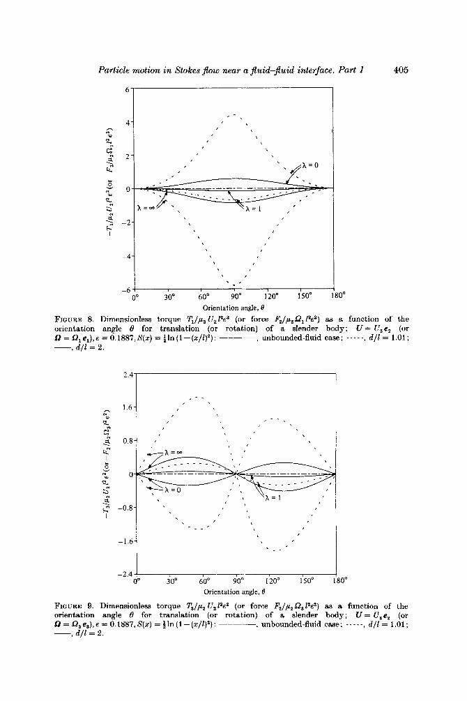
FIGURE 8. Dimensionless torque !l'Jp2 U212c2 (or force F2/p2Q, W) as a function of the orientation angle 6 for translation (or rotation) of a slender body; U = U2e, (or Q = Q, el), E = 0.1887, S(z) = 1 In (1 - (z/l),) : ----- , unbounded-fluid case ; - - - - -, d / l = 1.01 ; -, d / l = 2.
2.4
1.6 h n
c
2 0.8 $ . 7 2 c 0
s s
v - . < -0.8
1
-1.6
-2.4
. - -
> 90' 120' 150' 30" 60" Orientation angle, 8
3 0"
a function of the FIGURE 9. Dimensionless torque T3/p2 U , lacz (or force F2/pz Q3 1W) as orientation angle 8 for translation (or rotation) of a slender body; U = U,ez (or Q=Q,e3),e=0.1887,S(z) = t l r ~ ( l - ( z / l ) ~ ) : ----- , unbounded-fluid case ; - - - - -, d / l = 1.01 ; -? d / l = 2.
406 S.-M. Yang and L. G. Leal
relative to that in an unbounded flow for all d l l . Furthermore, there is an induced torque due to the interactions between the particle and interface, which will cause the particle to rotate in the absence of externally applied couples - Tl and - T3. It may be noted that the sensitivity of drag to the orientation angle is very weak. In the particular case of A = 1, the drag force is, in fact, nearly constant irrespective of8. Although the drag force F, must be independent of 8 in an unboundedjuid, this would certainly not be expected in the presence of the interface. Figure 8 shows that, for a given A , the x1 component of the angular velocity due to the induced torque TI will always have the same sign regardless of 8. On the other hand, the induced torque T3 always changes sign at the orientation angles 8 = 0' (or 180') and 90° independent of the viscosity ratio A and dll as shown in figure 9.
The implication of these somewhat complicated results for the trajectories of a slender particle moving under the action of a force in the x2 (or x l ) direction will be considered later in the paper.
3.3. Motion normal to the interface along the x3 axis Finally, let us turn to the problem of a slender body that is translating normal to a plane fluid-fluid interface. The no-slip boundary condition on the body surface is u(xB) = U3e3. As before, this condition cannot be satisfied by a line distribution of Stokeslets alone, since the corresponding integral equations contain an 7-dependence at O(e2) , and a line distribution of potential dipoles is again required with a strength
B(x) = -$rt(x) a (x ) .
The corresponding Stokeslet distribution is given by
al(z) = - t sin 28 U3[€ - $e2(2S(x) + 3 + D ( x ; A , 8 , d ) ) ] + 0(c3),
+ C(z; A , 8, d ) + 0 ( € 3 ) . 11 3 cos2e- 1 u3 €-- 2S(x)+ 1+c0s2e 4 [ ;( cos2e+i
a3 =
(20b)
For the perpendicular orientation, u l (x ) = 0 and a3(x) can be obtained simply by substituting 8 = 90' and b(x ; A , d ) for C ( X ; A , 8, d ) into (20b) (b (x ; A , d ) , C ( X ; A , 8, d ) and D ( x ; A , 8, d ) are given in the Appendix).
The total force and hydrodynamic torque acting on a circular cylindrical slender body which translates with velocity U = U3 e3 are
Fl = 2zp, U31sin28e D(z;A,e,d)dz +O(e3) , 11 + [ C(x ; A, 8, d ) dz)]
3c0s2e-i 2(c0s2e+ 1 ) 41 -, F3 = - 4 ~ p ~ U ~ 1 ( ~ 0 ~ ~ 8 + 1 ) €
+ 0 (c3), (21 b )
(22) 1
T, = - 2zp2 U3 cos Be2 x J ( x ; A, 8, d ) dx+ 0(c3). J-, These results for Fl, F3 and T, are plotted in figures 1@12 as a function of the
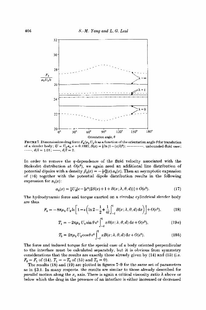
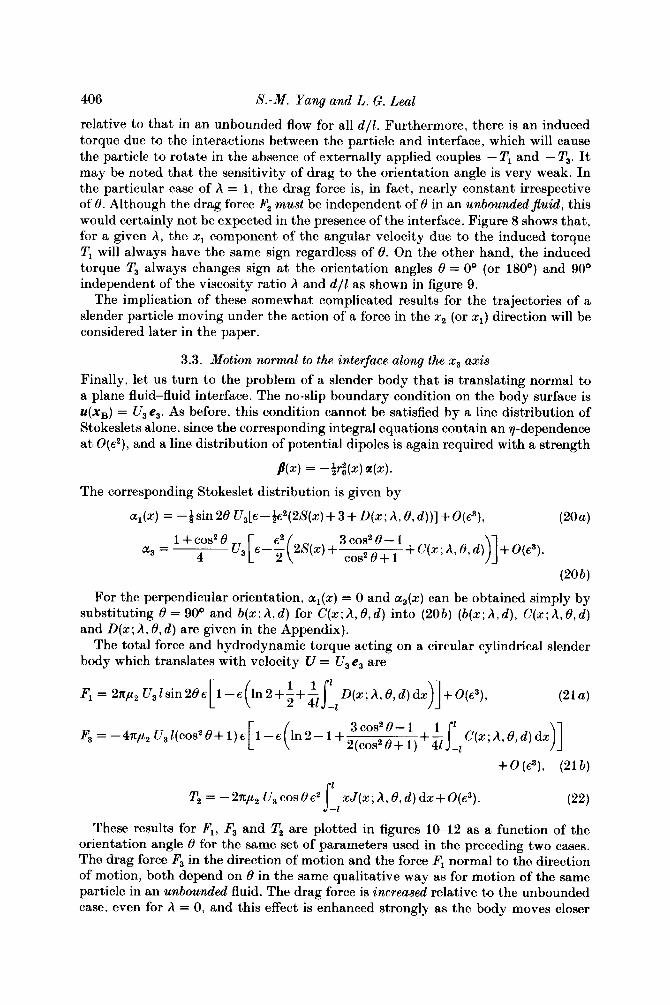
orientation angle 8 for the same set of parameters used in the preceding two cases. The drag force F3 in the direction of motion and the force Fl normal to the direction of motion, both depend on 8 in the same qualitative way as for motion of the same particle in an unbounded fluid. The drag force is increased relative to the unbounded case, even for A = 0, and this effect is enhanced strongly as the body moves closer
Particle motion in Stokes $ow near a &id-juid interface. Part 1 407
36
12 ! O0 30' 60" 90" 120" 150' 1
Orientation angle, 0
30"
FIQURE 10. Dimensionless drag force FJp2 U31e as a function of the orientation angle 6' for translationofaslenderbody; U = U,e,,e = 0.1887,5(~) = tln(l-(r/l)2):----- ~ unbounded- fluid case; - - - - - , d / l = 1.01; -, d / l = 2 .
'_1 8
4
0
-4
- 1 2 1 0" 30' 60' 90" 120' 150'
Orientation angle, 0
30"
FIGURE 11. Dimensionless normal force F,/y2 U,ls as a function of the orientation angle 6' for translationofaslenderbody; U = U,e,,s = 0.1887,S(z) = ~ l n ( l - ( ~ / l ) ~ ) : - - - - - , unbounded- fluid case; -----, d / l = 1.01; -, d / l = 2 .
408 S.-M. Yang and L. G . Leal
-4 ! I
0" 30" 60" 90" 120" 150" 180"
Orientation angle, B
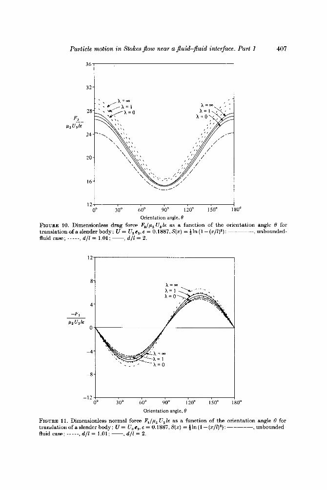
FIQURE 12. Dimensionless torque T2/,u2 U, laca (or force F3/,u2 O2 12c2) as a function of the orientation angle B for translation (or rotation) of a slender body; U = Use, (or B = O , ~ , ) , E = 0.1887, S(x) = In (1 - ( x / l ) 2 ) : - - - -, d / l = 1.01 : -, d / l = 2 ; unbounded-fluid case.
to the interface. The force normal to the direction of motion is also increased in absolute magnitude with increases of A or decrease of d l l . It will be noted that Fl changes sign at 6 = 0 and 90°. Thus, for Oo < 6 < 90°, motion toward the interface will induce translation in the positive ' 1 '-direction in the absence of an applied force -Fl , while the induced translation will be in the negative l-direction for 90° < 6 < 1 8 0 O . Finally, the hydrodynamic torque T2 induced by the presence of the interface means that a freely suspended slender body (one with T = 0 ) cannot translate towards the interface without simultaneously rotating unless the body is oriented parallel or perpendicular to the interface. The former orientation (6 = 0') is a stable equilibrium point for all A and d l l while the latter (6 = 90°) is unstable. Thus, a slender body with an arbitrary initial oblique angle (6 =I= 90°) relative to an inte&ce tends to rotate, in the absence of an applied torque -T, to a parallel orientation as the body translates towards the interface for all A.
This completes our detailed study of fundamental solutions of Stokes' equations for translational motion of an arbitrarily oriented slender body in the three mutually orthogonal axis directions specified in figure 1. We shall turn shortly to the application of these solutions for trajectory calculations. First, however, in view of the induced hydrodynamic torque that exists due to translational motion near an interface, it is necessary to determine the fundamental solutions for rotation of a slender body near an interface.
Particle motion in Stokes Jlow near a Jluid-Jluid interface. Part 1 409
4. Fundamental solutions for rotation of a slender body near a flat fluid interface
We turn now to the case of a slender body rotating with an angular velocity B in the presence of a plane fluid-fluid interface. Since the problem is linear, the solution for rotation with an arbitrary angular velocity can be obtained by superposition of the three independent solutions in which the axis of rotation is parallel to one of the three orthogonal xi (i = 1,2,3) axes. As noted earlier, solution of these three fundamental problems will provide all of the components of the hydrodynamic resistance tensors that are not obtainable from the results of 93.
First let us consider a rotating slender body when the axis of rotation is parallel to the x, axis (i.e. 51 = Q, el). In this case, the no-slip boundary condition on the body surface is given by
u(xB) = [0, - (x sin 8 + ro sin 9 cos 8 ) Q,, r,, cos 9Q1].
We have performed an asymptotic expansion of the integral equation (4) with this boundary condition, using a similar approach to the case of translational motion, and found the required line distributions of Stokeslets and potential dipoles,
a2(x) = -&?,xs in8[~-$~(2S(~)- 1 +K(x;A,8,d))]+O(s3). (23)
The leading term in the line distribution of Stokeslets has a linear dependence on the distance x from the body centre, as a consequence of the fact that the magnitude of the velocity near the body surface (i.e. lx-xBl/Z < 1) is also proportional to the distance x for this rotational motion.
Evaluating (10) and ( l l ) , we obtain the total torque and force acting on a cylindrical slender body which rotates with angular velocity a, el :
T, = -~n,u,Q,13sin28s x2K(x;A,8,d)dx
y3 = -Tlcote, (24b)
(25)
When a particle is oriented perpendicular to the interface, the torque and induced force can be obtained simply by substituting 8 = 90°, c ( x ; A, d ) for K(x; A, 8, d) and a(x; A, d) for B(x; A, 8, d) into (24a, b) and (25) (c(x; A, d) and K(x; A, 8, d) are given in the Appendix). Batchelor (1970) considered the rotation of a straight rigid slender body of an arbitrary cross-section in an in$nite quiescent fluid, and calculated a hydrodynamic torque which is identical to (25a) with 8 = 90° up to order of s.
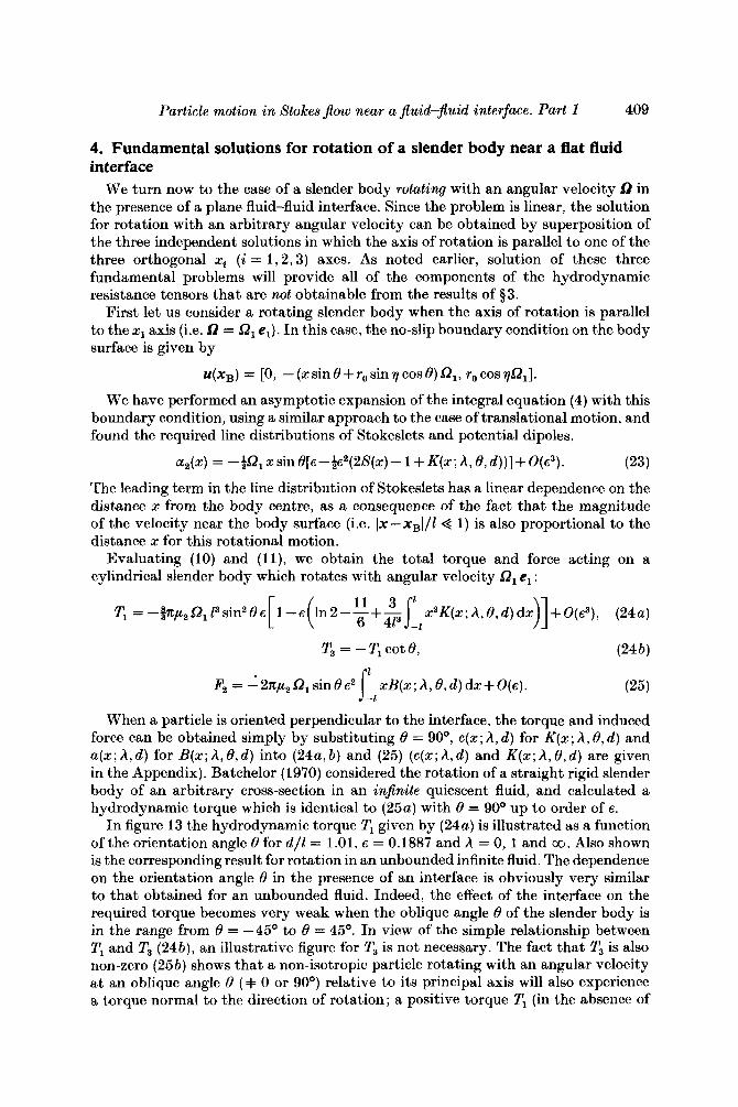
In figure 13 the hydrodynamic torque T, given by (24a) is illustrated as a function of the orientation angle 8 for d/l = 1 . 0 1 , ~ = 0.1887 and A = 0 , l and 00. Also shown is the corresponding result for rotation in an unbounded infinite fluid. The dependence on the orientation angle 8 in the presence of an interface is obviously very similar to that obtained for an unbounded fluid. Indeed, the effect of the interface on the required torque becomes very weak when the oblique angle 8 of the slender body is in the range from 8 = -45' to 8 = 45O. In view of the simple relationship between T, and T3 (24b), an illustrative figure for T3 is not necessary. The fact that T3 is also non-zero (25b) shows that a non-isotropic particle rotating with an angular velocity at an oblique angle 8 (+ 0 or 90°) relative to its principal axis will also experience a torque normal to the direction of rotation; a positive torque T, (in the absence of
1 F2 = -2n,u2 Q, sin 8 s2 xB(x; A, 8, d) dx+ O(s) . i_,
410 S.-M. Yang and L. G. Leal
12?
0 0' 30' 60' 90" 120' 150' I
Orientation angle, B
;0'
FIQURE 13. Dimensionless torque TJp , a, 1% as a function of the orientation angle 8 for rotation ofaslender body;a=l2,e1,d/Z= 1.01,~=0.1887,S(z) =?jln(l-(s/Z)*):----- , unbounded- fluid case. The force F, induced by this rotation (owing to the presence of the interface) is given in figure 8.
an applied torque -T3) will induce a simultaneous rotation in the 3-direction, provided # += 0' or 90O. The existence of a critical viscosity ratio separating cases of increasing or decreasing torque, evident in figure 13, is similar to the results of Lee et al. (1979) for rotation of a sphere with an angular velocity sd = 0, el near a flat interface.
A particle rotating near a flat interface will also experience a hydrodynamic force F, due solely to the presence of the interface, given by (25). The dimensionless force - Fz/p2 Q, 12e2 required to sustain the specified rotational motion (sd = 0, el) without translation is, in fact, identical with the dimensionless torque - TJp, U , 12e2 required to sustain the translational motion ( U = U, e,) without rotation, which was illustrated previously in figure 8. This equality is expected on general theoretical grounds for Stokes flow with linear boundary conditions. In the absence of a force - F,, rotation in the l-direction will induce translation in the 2-direction. The sign of the induced translational velocity depends only on the viscosity ratio A.
Now let us consider a rotating slender body whose rotation axis is parallel to the x2 axis. With the fluid velocity on the body surface,
u(xB) = [(x sin 8 + r,, sin 7 cos 8) Q,, 0, - (x cos 8- ro sin 7 sin 8) Q,],
the required line distribution of Stokeslets and potential dipoles is as follows:
al(x) = ~sinBQ,xs[l -+s(2S(x) - 1 + G ( z ; h , 8 , d ) ) ] + O ( s 3 ) , (26a)
Particle motion in Stokes $ow near a fEuid-jluid interface. Part 1 41 1
1 9.8
9.6 I O0 30" 60" 90' 120" 150' 1 30°
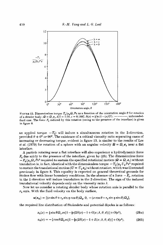
Orientation angle, 0 FIQURE 14. Dimensionless torque T,/,u, 0, Pe as a function of the orientation angle 0 for rotation of a slender body; 0 = &e,, e = 0.1887, S(z) = !jln (1 -(z/Z)'): ----- , unbounded-fluid case; _ - - - - , d / l = 1.01 ; -, d / l = 2. The force components Fl and F, induced by this rotation are shown respectively in figures 5 and 12.
The total torque and induced force on the particle can be readily evaluated from the foregoing distribution of Stokeslets :
T, =-% " IR Z3e [ 1--s ( ln2--11+3f 6 413 zzL(s;A,8,d)ds)]+O(~3), (27)
Fl = 2np2 SZ, sin 8e2 zH(x ; A , 8, d ) dz + O(e3) ,
1 F3 = - 27tp2 SZ, cos 8s' zJ (x ; A, 8 , d ) dz + O(e3) . (28 b) s_,
I 1
For the perpendicular orientation, F3 = 0, 1
Fl = 2np21R,e2 za(z;A,d)dz+O(e3),
and T2 can be obtained by substituting c ( x ; A , d ) for L(z; A , 8, d) into (27). The hydrodynamic torque T, corresponding to the specified rotational motion SZ, e2
is plotted in figure 14 for a circular cylindrical slender body as a function of the oblique angle 8 for d / l = 1.01 and 2,e = 0.1887 and three values of A = 0, l and CX) . Also shown is the corresponding result for rotation in an unbounded fluid. It is evident that the hydrodynamic torque T, in an unbounded fluid must be independent of the orientation angle 8 as shown (indeed, this torque is simply given by (27) with L(z; A , 8, d) = 0). However, the torque in the presence of an interface can be seen to deviate significantly from that in an unbounded fluid with the details depending on the viscosity ratio and on the orientation and position of the body (i.e. 8 and d). Given
FLM 136 14
412 S.-M. Y a n g a n d L. G. Leal
I I I I I
Orientation angle, 0
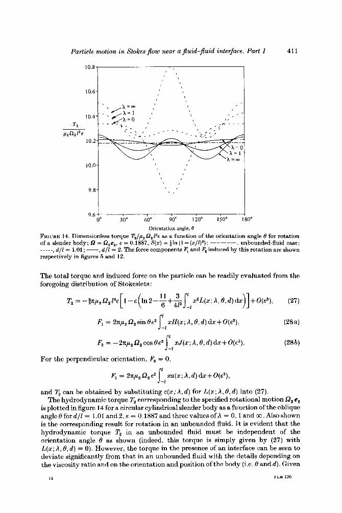
FIGURE 15. Dimensionless torque T3/,u2 Q3 1% as a function of the orientation angle 8 for rotation of a slender body; D = Q,e,,d/2 = 1.01,~ = 0.1887,S(x) =+In (l-(z/Z)*): ----, unbounded-fluid case. The force component F, induced by this rotation is shown in figure 9.
d / l ( = 2) and E (= 0.1887), for example, a slender body rotating near a plane solid wall (h+co) experiences a larger hydrodynamic torque than it would in an un- bounded fluid for a certain range of 8 (i.e. -21' < 8 < 21' or 75' < 8 < 105'), but a smaller torque for 21' < 8 < 75' or 105' < 8 < 159'. Further, the torque becomes increasingly sensitive to the orientation angle 8 as the viscosity ratio h is increased. For example, in the free-surface case (i.e. A+O) , the torque is still very nearly independent of 8 while, in the solid-wall case (i.e. h+co), the relative deviation is larger.
As in the case of rotational motion in the l-direction, there exists an induced hydrodynamic force in the present case, which is due to the presence of the interface. The dimensionless induced forces FJp2 9, 12e2 and F3/p2 Q, 12e2 in this case are actually identical with the dimensionless induced torques T2/p2 U , 12e2 and T2/p2 U, Z2e2 for translation in the 1- and 3-directions respectively (again as expected). The direction of the induced force Fl given by (28a) depends on the viscosity ratio and on the orientation and position of the body (i.e. 8 and d ) , cf. figure 5. However, the direction of action of the induced force F3 obtained from (28b) depends only on the orientation angle 8 (see figure 12).
Finally we consider a slender body rotating near a plane interface with an angular velocity 52 = 9, e3. The line distribution of Stokeslets and potential dipoles necessary to satisfy the no-slip boundary condition is
(29) The total torque and induced force exerted on a cylindrical slender body are then
a2(x) = ~ C O S 8O,zs[l -4~(2S(x)- 1 + K ( x ; A , 8, d ) ) ] + O ( e 3 ) .
TI = @pz Q, Z3 sin 286 1 --E In 2- f i+A x2K(z ; A, 8, d ) dx)] + 0 ( e 3 ) , (30a) [ ( 6 4% -1
T3 = - c o ~ ~ T , , r l
F2 = ~ Z ~ ~ Q , C O S € ' E ~ J zB(x;A,8,d)dx+o(~3). -1
Particle motion in Stokes $ow near a Jluid-Jluid interface. Part 1 413
For the body oriented perpendicular to the interface, the total torque can be shown to be O(Ro/l, Ro/d) , and the induced force is obviously zero. This latter result is in agreement with the quiescent infinite-fluid case analysed by Batchelor (1970).
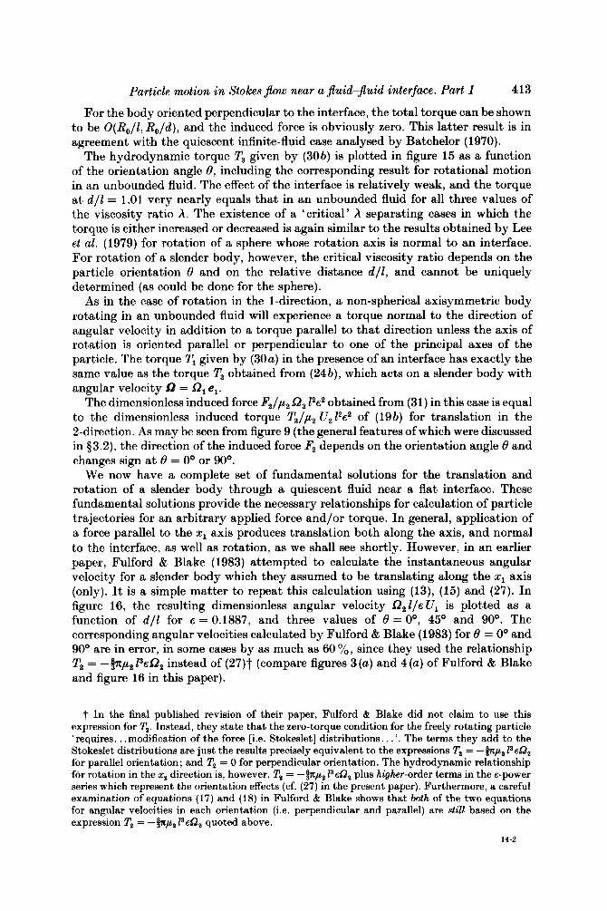
The hydrodynamic torque T3 given by (30b) is plotted in figure 15 as a function of the orientation angle 8, including the corresponding result for rotational motion in an unbounded fluid. The effect of the interface is relatively weak, and the torque at d / l = 1.01 very nearly equals that in an unbounded fluid for all three values of the viscosity ratio A. The existence of a 'critical' A separating cases in which the torque is either increased or decreased is again similar to the results obtained by Lee et al. (1979) for rotation of a sphere whose rotation axis is normal to an interface. For rotation of a slender body, however, the critical viscosity ratio depends on the particle orientation 8 and on the relative distance d/E, and cannot be uniquely determined (as could be done for the sphere).
As in the case of rotation in the l-direction, a non-spherical axisymmetric body rotating in an unbounded fluid will experience a torque normal to the direction of angular velocity in addition to a torque parallel to that direction unless the axis of rotation is oriented parallel or perpendicular to one of the principal axes of the particle. The torque T, given by (30a) in the presence of an interface has exactly the same value as the torque T3 obtained from (24b), which acts on a slender body with angular velocity D = G?, el.
The dimensionless induced force F2/p2 G?, 12s2 obtained from (31) in this case is equal to the dimensionless induced torque T3/,u2 U212e2 of (19b) for translation in the 2-direction. As may be seen from figure 9 (the general features of which were discussed in §3.2), the direction of the induced force F2 depends on the orientation angle 8 and changes sign at 8 = 0' or 90'.
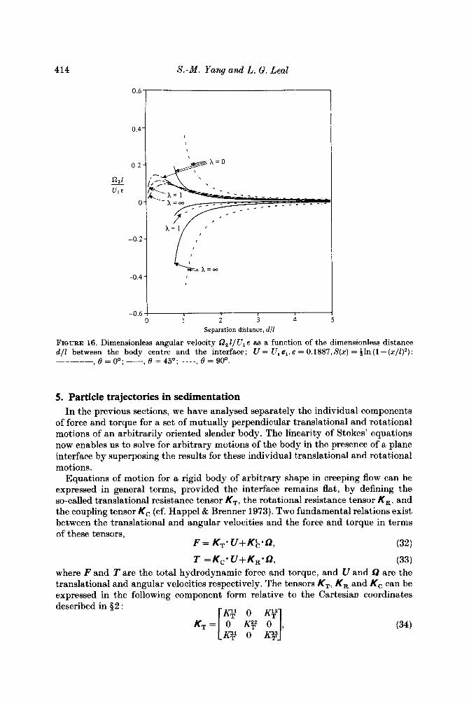
We now have a complete set of fundamental solutions for the translation and rotation of a slender body through a quiescent fluid near a flat interface. These fundamental solutions provide the necessary relationships for calculation of particle trajectories for an arbitrary applied force and/or torque. In general, application of a force parallel to the x1 axis produces translation both along the axis, and normal to the interface, as well as rotation, as we shall see shortly. However, in an earlier paper, Fulford & Blake (1983) attempted to calculate the instantaneous angular velocity for a slender body which they assumed to be translating along the x1 axis (only). It is a simple matter to repeat this calculation using (13), (15) and (27). In figure 16, the resulting dimensionless angular velocity Q21/~U1 is plotted as a function of d / l for E = 0.1887, and three values of 8 = O', 45' and 90'. The corresponding angular velocities calculated by Fulford & Blake (1983) for 8 = 0' and 90' are in error, in some cases by as much as 60 %, since they used the relationship T2 = -@p2 PEG?, instead of (27)t (compare figures 3 (a) and 4 (a) of Fulford & Blake and figure 16 in this paper).
t In the final published revision of their paper, Fulford & Blake did not claim to use this expression for T,. Instead, they state that the zero-torque condition for the freely rotating particle 'requires. . .modification of the force [i.e. Stokeslet] distributions. . . '. The terms they add to the Stokeslet distributions are just the results precisely equivalent to the expressions T, = -&, l3eQz for parallel orientation ; and T, = 0 for perpendicular orientation. The hydrodynamic relationship for rotation in the x, direction is, however, T, = -inp2 PeQ, plus higher-order terms in the €-power series which represent the orientation effects (cf. (27) in the present paper). Furthermore, a careful examination of equations (17) and (18) in Fulford & Blake shows that both of the two equations for angular velocities in each orientation (i.e. perpendicular and parallel) are still based on the expression T, = -fnp2 FeQ, quoted above.
14-2
414 8.-M. Yang and L. G. Leal
0.6
0.4'
0.2
n,l u1 E
0
-0.2
-0.4
-0.6
,
, I
1 2 3 4 Separation distance, d/Z
FIGURE 16. Dimensionless angular velocity a, Z/U, E as a function of the dimensionless distance d / l between the body centre and the interface; U = U , e , , e = 0.1887,S(x) = ~ l n ( l - ( x / l ) z ) :
0 = 00; - 0 = 450; ____ , 0 = goo.
5. Particle trajectories in sedimentation In the previous sections, we have analysed separately the individual components
of force and torque for a set of mutually perpendicular translational and rotational motions of an arbitrarily oriented slender body. The linearity of Stokes' equations now enables us to solve for arbitrary motions of the body in the presence of a plane interface by superposing the results for these individual translational and rotational motions.
Equations of motion for a rigid body of arbitrary shape in creeping flow can be expressed in general terms, provided the interface remains flat, by defining the so-called translational resistance tensor KT, the rotational resistance tensor KR, and the coupling tensor Kc (cf. Happel & Brenner 1973). Two fundamental relations exist between the translational and angular velocities and the force and torque in terms of these tensors,
F = KT* U+ K&*Q,
T = Kc. U+ KR.0,
(32)
(33) where F and Tare the total hydrodynamic force and torque, and U and f2 are the translational and angular velocities respectively. The tensors KT, KR and K, can be expressed in the following component form relative to the Cartesian coordinates described in $2 :
(34)
Particle motion in Stokes flow near a fluid-fluid interface. Part 1 415
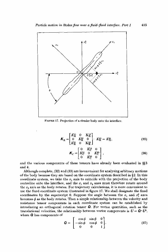
FIGURE 17. Projection of a slender body onto the interface.
and the various components of these tensors have already been evaluated in $53 and 4.
Although complete, (32) and (33) are inconvenient for analysing arbitrary motions of the body because they are based on the coordinate system described in $2. In this coordinate system, we take the x1 axis to coincide with the projection of the body centreline onto the interface, and the x1 and x2 axes must therefore rotate around the x3 axis as the body rotates. For trajectory calculations, it is more convenient to use the fixed coordinate system illustrated in figure 17. We shall designate the fixed coordinates by the superscript 0. Suppose the angle between the x1 and x: axes becomes # as the body rotates. Then a simple relationship between the velocity and resistance tensor components in each coordinate system can be established by introducing an orthogonal rotation tensor Q. For vector quantities, such as the translational velocities, the relationship between vector components is U = Q * UD, where Q has components of [ c;$ sin#
Q = -sin$ cos# . (37) 0 1
416 S.-M. Yang and L. G. Leal
Furthermore, the same relationship applies also to the forces, torques and angular velocities in the two coordinate systems. By substituting these relationships into (32) and (33), we have
F'= K&*UO+Kot*QO (38)
To = K$* UO+Kk.Qo (39)
KO = Q-1.K.Q (40)
c *
where the KO and K are related by
for each of the translation, rotation and coupling tensors. With the preceding relationships established for the resistance tensors, the
velocity vectors and the force and torque vectors all based on a fixed coordinate system, we can readily apply (38) and (39) to general trajectory calculations. For example, let us consider the motion of a slender body near a plane fluid-fluid interface under the action of an external force F'* and torque To*. An instantaneous solution for U" and Q0 is easily obtained from (38) and (39) :
(41)
(42)
It is convenient to represent the particle trajectories corresponding to (41) and (42) in terms of the position vector xp of the body centre and the orientation angles (i.e. Euler's polar angles) 8 and $ of the body axis relative to the plane of the interface (for the definitions of 8 and $ see figures 1 and 17). The relationships between UO and 5 1 O and time rate of changes in xp, 8 and $ (simply kp, 6 and 4) are as follows:
U" = -(KO T- KOtmKO-l-KO c)-l*(~*-KOt*KO-l* Po*)
QO = -KO-1. R (To*+K;'uo). C R
dx k p = - L dt v o , (43)
These five simultaneous differential equations (43)-(45) in combination with (41) and (42) are solved below using a fourth-order Runge-Kutta method with appropriate initial conditions. We consider trajectories for the special cases of a torque-free slender body (TO = 0) under the action of non-dimensionalized forces
= e: perpendicular to the interface respectively. The purpose of these calculations is primarily illustrative. However, these two elementary trajectory problems are relevant to sedimentation phenomena near an interface, as well as being qualitatively related to the processes of particle capture at the surface of a larger bubble or drop which may be viewed as locally planar in the limit where the particle is very much smaller than the collector. First, we begin with the particle motion due to an external force parallel to the interface. This problem for the limit h = 00 was previously considered, both theoretically and experimentally, by Russel et al. (1977). In figure 18, the trajectories for a slender body initially located at x: = ( O , O , 2) with initial orientations B0 = Oo, 12O, 22O, 50° and 79O and $o = Oo are plotted in terms of the separation distance d / l and the angle of inclination 0 relative to the interface for three values of A = 0, 1 and a. In this case (q50 = O O ) , the axis of the particle is initially in the plane defined by the force and the
= Fo/IFoI = ey parallel to the interface and
Particle motion in Stokes flow near a fluid-Jluid interface. Part 1 417
3 .O
2.5
2 .o ? -Y
al u
5 - Z 1.5
E 3
C .- 1
1.0
0.5
0
Orientation angle, 0
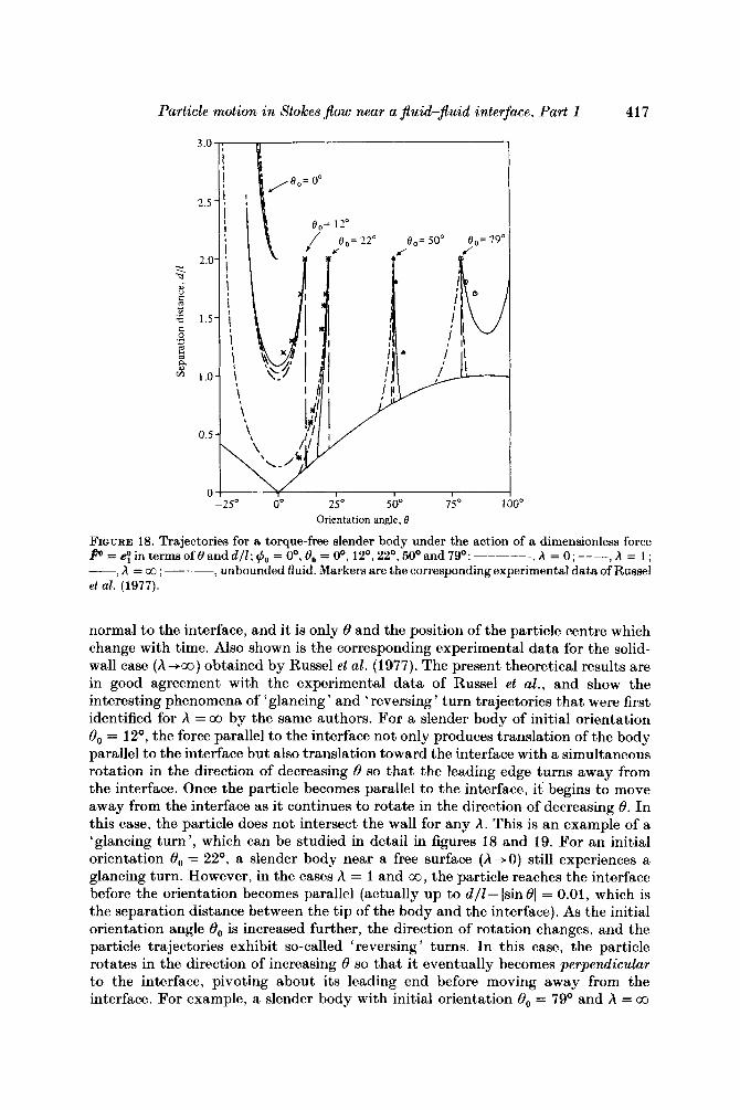
FIQURE 18. Trajectories for a torque-free slender body under the action of a dimensionless force f” = e! in terms of 8 and d l l ; rp0 = Oo, 8, = Oo, 12O, 22O, 50’ and 79O: A = 0; ----, A = 1 ; - h = a . - - - , unbounded fluid. Markers are the corresponding experimental data of Russel et al. (1977).
normal to the interface, and it is only 6 and the position of the particle centre which change with time. Also shown is the corresponding experimental data for the solid- wall case (h+00) obtained by Russel et al. (1977). The present theoretical results are in good agreement with the experimental data of Russel et al., and show the interesting phenomena of ‘glancing ’ and ‘reversing ’ turn trajectories that were first identified for A = 00 by the same authors. For a slender body of initial orientation O0 = 12O, the force parallel to the interface not only produces translation of the body parallel to the interface but also translation toward the interface with a simultaneous rotation in the direction of decreasing 6 so that the leading edge turns away from the interface. Once the particle becomes parallel to the interface, it begins to move away from the interface as it continues to rotate in the direction of decreasing 6. In this case, the particle does not intersect the wall for any A. This is an example of a ‘glancing turn’, which can be studied in detail in figures 18 and 19. For an initial orientation 8, = 22”, a slender body near a free surface (A+O) still experiences a glancing turn. However, in the cases A = 1 and 00 , the particle reaches the interface before the orientation becomes parallel (actually up to d/Z-lsinOI = 0.01, which is the separation distance between the tip of the body and the interface). As the initial orientation angle O0 is increased further, the direction of rotation changes, and the particle trajectories exhibit so-called ‘reversing ’ turns. In this case, the particle rotates in the direction of increasing 6 so that it eventually becomes perpendicular to the interface, pivoting about its leading end before moving away from the interface. For example, a slender body with initial orientation B0 = 79O and h = 00
418 S.-M. Yang and L. G. Leal
I I I
12 24 36 48 (
Dimensionless distance, x / l
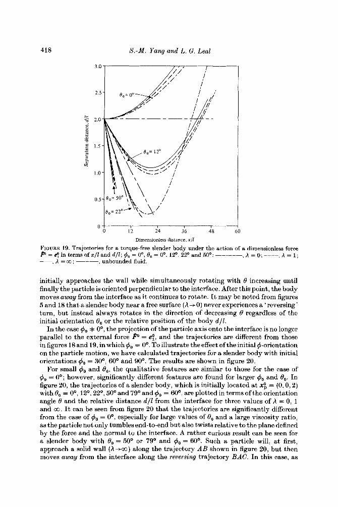
FIQURE 19. Trajectories for a torque-free slender body under the action of a dimensionless force P = e! in terms of x / 1 and d l l ; $o = O', Oo = O', 12', 22' and 50': -----, A = 0; ----, A = 1 ; -, A = a3 ; ---, unbounded fluid.
initially approaches the wall while simultaneously rotating with 8 increasing until finally the particle is oriented perpendicular to the interface. After this point, the body moves away from the interface as it continues to rotate. It may be noted from figures 5 and 18 that a slender body near a free surface ( A -+ 0) never experiences a ' reversing ' turn, but instead always rotates in the direction of decreasing 8 regardless of the initial orientation 8, or the relative position of the body dll .
In the case 4, + O", the projection of the particle axis onto the interface is no longer parallel to the external force ffo = e!, and the trajectories are different from those in figures 18 and 19, in which 4, = 0". To illustrate the effect of the initial $-orientation on the particle motion, we have calculated trajectories for a slender body with initial orientations 4, = 30°, 60" and 90". The results are shown in figure 20.
For small $, and 8,, the qualitative features are similar to those for the case of 4, = 0"; however, significantly different features are found for larger 4, and 8,. In figure 20, the trajectories of a slender body, which is initially located a t x; = (0, 0,2) with 8, = O", 12", 22", 50" and 79" and 4, = 60°, are plotted in terms of the orientation angle 8 and the relative distance d l l from the interface for three values of h = 0, 1 and co. It can be seen from figure 20 that the trajectories are significantly different from the case of 4, = O", especially for large values of 8, and a large viscosity ratio, as the particle not only tumbles end-to-end but also twists relative to the plane defined by the force and the normal to the interface. A rather curious result can be seen for a slender body with 8, = 50' or 79' and 4, = 60". Such a particle will, at first, approach a solid wall (A-+co) along the trajectory A B ahown in figure 20, but then moves away from the interface along the reversing trajectory BAC. In this case, as
Particle motion in Stokes jlow near a jluid-jluid interface. Part 1 419
3 .O
2.5
2.0 % -a ai K 1
a 1,s 0 .* 1 s 3 v2
1 .o
0.5
0 2so oo 25" soo I S 0 1 oo'
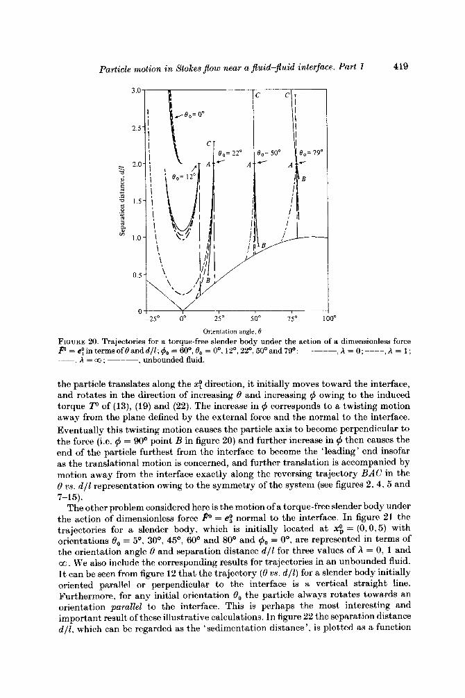
Orientation angle, f3 FIGURE 20. Trajectories for a torque-free slender body under the action of a dimensionless force P = ey in terms of 0 and d l l ; $,, = 60°, O0 = 0'. 1 2 O , 2 2 O , 50Oand 7 9 O : -----, h = 0; ----, A = 1 ; --, A = 03 ; ---, unbounded fluid.
the particle translates along the xf direction, it initially moves toward the interface, and rotates in the direction of increasing 8 and increasing q5 owing to the induced torque To of (13), (19) and (22). The increase in q5 corresponds to a twisting motion away from the plane defined by the external force and the normal to the interface. Eventually this twisting motion causes the particle axis to become perpendicular to the force (i.e. q5 = 90° point B in figure 20) and further increase in q5 then causes the end of the particle furthest from the interface to become the 'leading' end insofar as the translational motion is concerned, and further translation is accompanied by motion away from the interface exactly along the reversing trajectory BAC in the 0 21s. d / l representation owing to the symmetry of the system (see figures 2, 4, 5 and
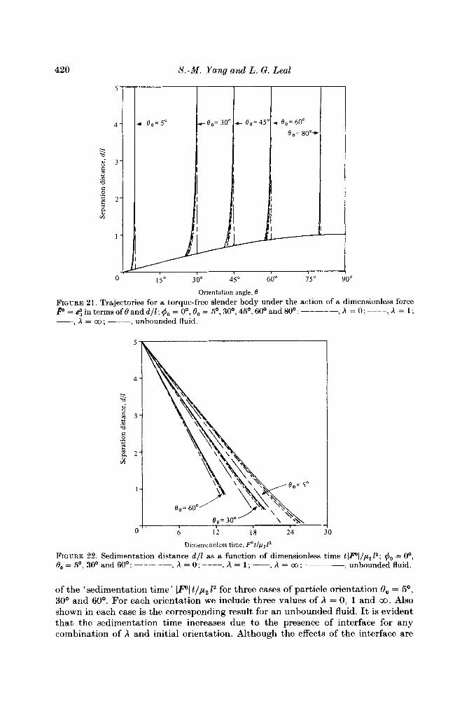
The other problem considered here is the motion of a torque-free slender body under the action of dimensionless force = e! normal to the interface. I n figure 21 the trajectories for a slender body, which is initially located a t X: = (0,0,5) with orientations 8, = 5 O , 30°, 45O, 60° and 80° and q50 = Oo, are represented in terms of the orientation angle 8 and separation distance d / l for three values of A = 0, 1 and 00. We also include the corresponding results for trajectories in an unbounded fluid. It can be seen from figure 12 that the trajectory (8 us. d l l ) for a slender body initially oriented parallel or perpendicular to the interface is a vertical straight line. Furthermore, for any initial orientation 8, the particle always rotates towards an orientation parallel to the interface. This is perhaps the most interesting and important result of these illustrative calculations. I n figure 22 the separation distance d l l , which can be regarded as the 'sedimentation distance', is plotted as a function
7-15).
420
0 15" 3 0" 45O 60" 75" 90"
Orientation angle, B FIQURE 21. Trajectories for a torque-free slender body under the action of a dimensionless force f" = e! in terms of 8 and d l l ; I$, = Oo, 8, = 5 O , 30°, 4 5 O , 60' and 80': -----, A = 0; ----, h = 1 ; -, h = 03 ; ---, unbounded fluid.
Dimensionless time, p t / p z 1 2
= 0; ----, A = 1 ; __ FIGURE 22. Sedimentation distance d l l as a function of dimensionless time t IF'l/p, P ; I$o = Oo, 8 0 - - 50, 300 and 600: -----, __-__ , unbounded fluid. =
of the 'sedimentation time' IF'\ tip2 l2 for three cases of particle orientation 8, = 5 O , 30° and 60°. For each orientation we include three values of A = 0, 1 and 00. Also shown in each case is the corresponding result for an unbounded fluid. It is evident that the sedimentation time increases due to the presence of interface for any combination of A and initial orientation. Although the effects of the interface are
Particle motion in Stokes $ow near a jluid-$uid interface. Part I 421
greatest when the particle is parallel to the interface, the difference from the unbounded-fluid case is always relatively small.
This completes our illustrative trajectory calculations using the fundamental solutions that were developed in $53 and 4. It is worth commenting that the scope of the analysis can be readily extended to calculate particle trajectories in any general linear flow field which is consistent with the presence of an interface.
This work was supported by a grant from the Fluid Mechanics Program of the National Science Foundation.
R E F E R E N C E S
ADEROQBA, K. & BLAKE, J. R. 1978 Action of a force near the planar surface between two semi-infinite immiscible liquids at very low Reynolds’ numbers. Bull. Austral. Math. SOC. 18, 345.
BATCHELOR, G. K. 1970 Slender-body theory for particles of arbitrary cross-section in Stokes flow. J. Fluid Mech. 44, 419.
BERDAN, C. & LEAL, L. G. 1982 Motion of a sphere in the presence of a deformable interface. I. Perturbation of the interface from flat: the effect on drag and torque. J. Colloid Znterface Sci. 87, 62.
Cox, R. G. 1970 The motion of long slender bodies in a viscous fluid. Part 1. General theory. J. Fluid Mech. 44, 419, 791.
Cox, R. G. 1971 The motion of long slender bodies in a viscous fluid. Part 2. Shear flow. J. Fluid Mech. 45, 625.
FULFORD, G. R. & BLAKE, J. R. 1983 On the motion of a slender body near an interface between two immiscible liquids at very low Reynolds number. J. Fluid Mech. 127, 203.
GOREN, S. L. & ~ ’ N E I L L , M. E. 1971 On the hydrodynamic resistance to a particle of a dilute suspension when in the neighborhood of a large obstacle. Chem. Engng Sci. 26, 325.
HAPPEL, J. & BRENNER, H. 1973 Low Reynolds Number Hydrodynamics. Noordhoff. JOHNSON, R. 1980 An improved slender-body theory for Stokes flow. J. Fluid Mech. 99, 411. JOHNSON, R. E. & Wu, T. Y. 1979 Hydrodynamics of low-Reynolds-number flow. Part 5. Motion
of a slender torus. J. Fluid Mech. 95, 263. KELLER, J. B. & RUBINOW, S. I. 1976 Slender-body theory for slow viscous flow. J . Fluid Mech.
75, 705. LEE, S. H., CHADWICK, R. S. & LEAL, L. G. 1979 Motion of a sphere in the presence of a plane
interface. Part 1 . An approximation solution by generalization of the method of Lorentz. J. Fluid Mech. 93, 705.
LEE, S. H. & LEAL, L. G. 1980 Motion of a sphere in the presence of a plane interface. Part 2. An exact solution in bipolar coordinates. J. Fluid Mech. 98, 193.
LEE, S. H. & LEAL, L. G. 1982 The motion of a sphere in the presence of a deformable interface. 11. A numerical study of the translation of a sphere normal to an interface. J. Colloid Interface Sci. 87, 81.
RUSSEL, W. B., HINCH, E. J., LEAL, L. G. & TJEFFENBRUCK, G. 1977 Rods falling near a vertical wall. J . Fluid Mech. 83, 273.
TILLETT, J . P. K. 1970 Axial and transverse Stokes flow past slender axisymmetric bodies. J. Fluid Mech. 44, 401.
TUCK, E. 0 . 1964 Some methods for flows past blunt slender bodies. J. Fluid Mech. 18, 619.