particulate monitoring systems - binmaster.commq1fuj-1fn/files/1068267... · particulate monitoring...
TRANSCRIPT

Particulate Monitoring Systems Installation & Operating Manual
Document No. 209-1009-B 2004
Particulate Monitoring Systems
BM 30 LGX Control Units
PS 10 Sensors
INSTALLATION & OPERATING
MANUAL
Division of Garner Industries, Inc. 7201 N. 98th
Lincoln, NE 68507 (800) 278-4241
www.binmaster.com
Particulate Monitoring Systems Installation & Operating Manual
Document No. 210-1003-G Page 1 ©2005
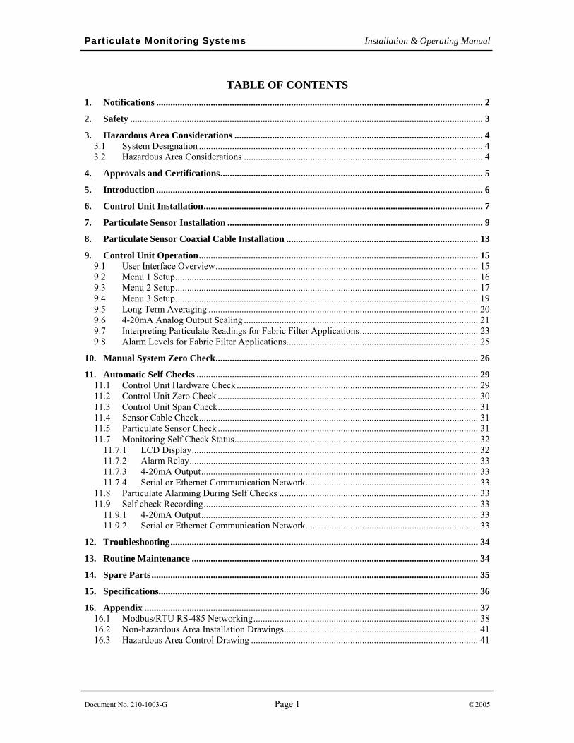
TABLE OF CONTENTS
1. Notifications .......................................................................................................................................... 2 2. Safety ..................................................................................................................................................... 3 3. Hazardous Area Considerations ......................................................................................................... 4
3.1 System Designation ........................................................................................................................ 4 3.2 Hazardous Area Considerations ..................................................................................................... 4
4. Approvals and Certifications............................................................................................................... 5 5. Introduction .......................................................................................................................................... 6 6. Control Unit Installation...................................................................................................................... 7 7. Particulate Sensor Installation ............................................................................................................ 9 8. Particulate Sensor Coaxial Cable Installation ................................................................................. 13 9. Control Unit Operation...................................................................................................................... 15
9.1 User Interface Overview............................................................................................................... 15 9.2 Menu 1 Setup................................................................................................................................ 16 9.3 Menu 2 Setup................................................................................................................................ 17 9.4 Menu 3 Setup................................................................................................................................ 19 9.5 Long Term Averaging .................................................................................................................. 20 9.6 4-20mA Analog Output Scaling ................................................................................................... 21 9.7 Interpreting Particulate Readings for Fabric Filter Applications.................................................. 23 9.8 Alarm Levels for Fabric Filter Applications................................................................................. 25
10. Manual System Zero Check............................................................................................................... 26 11. Automatic Self Checks ....................................................................................................................... 29
11.1 Control Unit Hardware Check ...................................................................................................... 29 11.2 Control Unit Zero Check .............................................................................................................. 30 11.3 Control Unit Span Check.............................................................................................................. 31 11.4 Sensor Cable Check...................................................................................................................... 31 11.5 Particulate Sensor Check .............................................................................................................. 31 11.7 Monitoring Self Check Status....................................................................................................... 32
11.7.1 LCD Display......................................................................................................................... 32 11.7.2 Alarm Relay.......................................................................................................................... 33 11.7.3 4-20mA Output..................................................................................................................... 33 11.7.4 Serial or Ethernet Communication Network......................................................................... 33
11.8 Particulate Alarming During Self Checks .................................................................................... 33 11.9 Self check Recording.................................................................................................................... 33
11.9.1 4-20mA Output..................................................................................................................... 33 11.9.2 Serial or Ethernet Communication Network......................................................................... 33
12. Troubleshooting.................................................................................................................................. 34 13. Routine Maintenance ......................................................................................................................... 34 14. Spare Parts.......................................................................................................................................... 35 15. Specifications....................................................................................................................................... 36 16. Appendix ............................................................................................................................................. 37
16.1 Modbus/RTU RS-485 Networking............................................................................................... 38 16.2 Non-hazardous Area Installation Drawings.................................................................................. 41 16.3 Hazardous Area Control Drawing ................................................................................................ 41
Particulate Monitoring Systems Installation & Operating Manual
Document No. 210-1003-G Page 2 ©2005
1. Notifications This document contains important information necessary for proper operation of the product. It is strongly urged that all users of the product read this manual in its entirety. All instructions should be followed properly and any questions that arise should be discussed with FilterSense (A Division of Impolit Environmental Control Corp.).
Any use or distribution of this document without the express consent of FilterSense (A Division of Impolit Environmental Control Corp.) is strictly prohibited. Any reproduction is prohibited without written permission.
In no event will FilterSense (A Division of Impolit Environmental Control Corp.) be liable for any mistake, including lost profits, lost savings, or other incidental or consequential damages arising out of the use or inability to use this manual, even if advised of the possibility of such damages, or any claim by any other party.
Identifies information about practices or circumstances that can lead to personal injury or death, property damage, or economic loss.
Warning statements help you to:
• Identify a hazard
• Avoid a hazard
• Recognize the consequences
Identifies information that is critical for successful application and
understanding of the product.
Identifies information, sections or statements in this manual that apply to approved hazardous area systems, regulations or installation.
IMPORTANT
Particulate Monitoring Systems Installation & Operating Manual
Document No. 210-1003-G Page 3 ©2005
2. Safety
DEVICE SUITABILITY
• Before installing any device confirm area classification requirements. Do not install any device that is not tagged as suitable for the required area classification.
• Before installing any device, confirm ambient temperature, process temperature and process pressure requirements. Do not install any device that is not tagged as suitable for the required temperatures and pressures.
This apparatus has been designed to comply with EN 61010, safety requirements for electrical equipment for measurement, control and laboratory use, and has been supplied in a safe condition. Before applying power, verify that the correct safety precautions have been taken (see the following warnings).
GROUNDING AND FUSING
• Before turning on the instrument, you must connect the protective earth terminal of the instrument to a proper earth ground. Grounding to the neutral conductor of a single-phase circuit is not sufficient protection.
• Only fuses with the required current, voltage and specified type should be used. Do not use repaired fuses or short-circuited fuse holders.
FIELD SERVICE
• Only appropriately licensed personnel should perform the mechanical and electrical installation.
• This device does not contain field serviceable components other than the line fuse. Only factory personnel should perform service on this equipment.
• WARNING – To prevent ignition of flammable or combustible atmospheres and for operator safety, always disconnect power before servicing.
Particulate Monitoring Systems Installation & Operating Manual
Document No. 210-1003-G Page 4 ©2005
3. Hazardous Area Considerations
3.1 System Designation Systems approved for use in hazardous areas contain the “HZ” designation in the model numbers for both the control unit and the particulate sensor.
Sections or statements in this manual that apply to approved hazardous area systems or installations are designated with the following symbol:
3.2 Hazardous Area Considerations The intrinsically-safe particulate sensor supplied with this equipment is suitable for use in the following locations when connected to an approved particulate monitor control unit:
Hazardous Location - Class I, Division 1, Groups A, B, C, D
Hazardous Location – Class II, Division 1, Groups E, F, G
Hazardous Location – Class III
Any Non-Hazardous Location
The following WARNING statement applies to use in hazardous locations.
EXPLOSION HAZARD
• Substitution of components may impair intrinsic safety.
• Do not connect or disconnect components unless power has been disconnected.
• Installation must be in accordance with ANSI/ISA RP12.6 and National Electric Code ANSI/NFPA 70, Article 504.
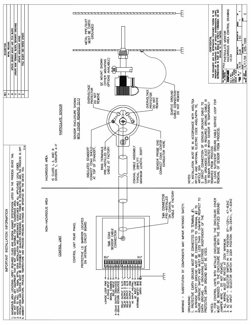
• Hazardous area control drawing 225-1005 must be followed for proper installation.
Particulate Monitoring Systems Installation & Operating Manual
Document No. 210-1003-G Page 5 ©2005
4. Approvals and Certifications
CE Conformant
The Control Units and Particulate Sensors conform to the appropriate country standards and governing regulations listed below:
• EN 61010/1993 “Safety requirements for electrical equipment for measurement, control and laboratory use.”
• EN 55011/1991 “Limits and methods of measurement of radio interference characteristics of industrial, scientific and medical equipment”. Class A: Industrial and commercial.
• EN50082-1/1993 “Electromagnetic compatibility – Generic immunity standard”. Part 1: Residential, commercial and light industry.
CSA Certified
This Particulate Monitoring system is certified by the Canadian Standards Association (to US and Canadian Standards) for use in hazardous locations as is specified below:
Particulate Sensor:
Intrinsically Safe for Hazardous Locations
Class I, Division 1, Groups A, B, C, and D
Class II, Division 1, Groups E, F, G
Class III
For use with the Control Units listed below, 200ºC maximum ambient.
Note: There is no temperature rise caused by electrical components. Temperature code is based only on ambient temperature, (e.g. a 200 °C ambient requires a T3 rating.)
Control Unit:
For use in Ordinary Locations Only
MODEL-HZ Control Unit rated 115 Vac/230 Vac, 0.1A or 24Vdc, 0.25A, -25ºC to 70°C, with intrinsically-safe output to Particulate Sensor.
Where: MODEL = Base model number
HZ = Approved for use with intrinsically-safe sensors
Particulate Monitoring Systems Installation & Operating Manual
Document No. 210-1003-G Page 6 ©2005
5. Introduction A Particulate Monitoring System consists of a control unit, a particulate sensor and a sensor coaxial cable. Applications include continuous emissions monitoring, baghouse filter leak detection and process particulate flow monitoring. Types of particulate include both solid particulates (dusts, powders, granulars and pellets) and liquid particulates (mists). Various control unit models and sensors are provided to match the application and process monitoring needs.
Principle of Operation Particulate Monitoring Systems employ a highly reliable technology based on induction. A sensor probe is mounted in an airflow stream such as a pipe, duct or stack (for small tubing an inline non-intrusive ring sensor is employed). As particulate flows near and over the sensing element, minute electrical currents are induced in the sensor and transferred to the control unit by a coaxial cable. A microprocessor filters and processes the signal into a normalized, absolute output that is linear to the mass concentration of particulate.
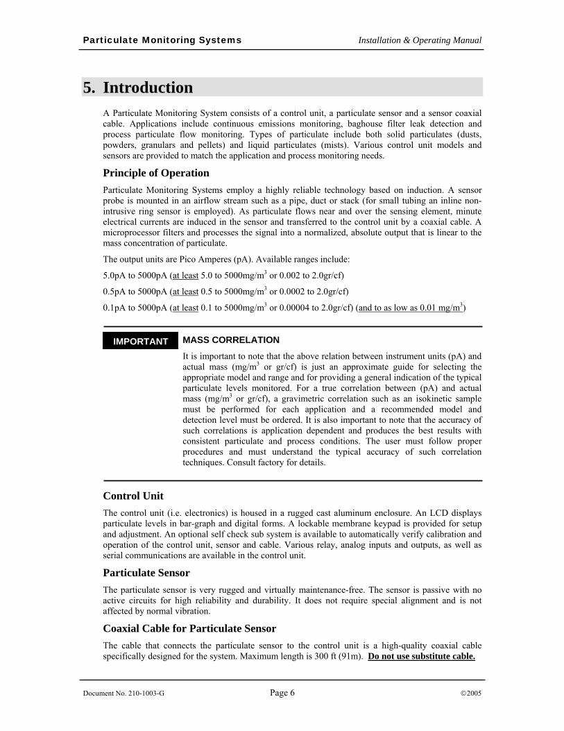
The output units are Pico Amperes (pA). Available ranges include:
5.0pA to 5000pA (at least 5.0 to 5000mg/m3 or 0.002 to 2.0gr/cf)
0.5pA to 5000pA (at least 0.5 to 5000mg/m3 or 0.0002 to 2.0gr/cf)
0.1pA to 5000pA (at least 0.1 to 5000mg/m3 or 0.00004 to 2.0gr/cf) (and to as low as 0.01 mg/m3)
_ MASS CORRELATION
It is important to note that the above relation between instrument units (pA) and actual mass (mg/m3 or gr/cf) is just an approximate guide for selecting the appropriate model and range and for providing a general indication of the typical particulate levels monitored. For a true correlation between (pA) and actual mass (mg/m3 or gr/cf), a gravimetric correlation such as an isokinetic sample must be performed for each application and a recommended model and detection level must be ordered. It is also important to note that the accuracy of such correlations is application dependent and produces the best results with consistent particulate and process conditions. The user must follow proper procedures and must understand the typical accuracy of such correlation techniques. Consult factory for details.
Control Unit The control unit (i.e. electronics) is housed in a rugged cast aluminum enclosure. An LCD displays particulate levels in bar-graph and digital forms. A lockable membrane keypad is provided for setup and adjustment. An optional self check sub system is available to automatically verify calibration and operation of the control unit, sensor and cable. Various relay, analog inputs and outputs, as well as serial communications are available in the control unit.
Particulate Sensor The particulate sensor is very rugged and virtually maintenance-free. The sensor is passive with no active circuits for high reliability and durability. It does not require special alignment and is not affected by normal vibration.
Coaxial Cable for Particulate Sensor The cable that connects the particulate sensor to the control unit is a high-quality coaxial cable specifically designed for the system. Maximum length is 300 ft (91m). Do not use substitute cable.
IMPORTANT

Particulate Monitoring Systems Installation & Operating Manual
Document No. 210-1003-G Page 7 ©2005
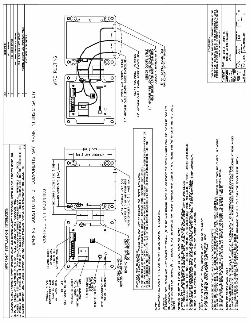
6. Control Unit Installation
INSTALLATION PERSONNEL
• Only appropriately licensed professionals should install this product.
• WARNING – To prevent ignition of flammable or combustible atmospheres and for operator safety, always disconnect power before servicing.
CONTROL UNIT LOCATION
• The control unit may only be located in ordinary locations (non-hazardous safe areas).
• Do not locate the control unit in a hazardous area unless it is inside an appropriately rated explosion-proof or purged enclosure and supplied as part of an approved hazardous area system with approved control unit and approved sensor assembly.
• Do not locate the control unit in or near sources of very high electrical noise such as a Variable Frequency Drive (VFD) or Motor Control Center. Locate the control unit at least 10 feet from these sources and, if possible, power the control unit from a separate power source. If power is supplied from the same branch circuit or a circuit containing electrical noise, install a quality line filter such as an Islatrol IC+102.
Location: The control unit should be mounted in a position that is convenient for setup and operation. It should be located at eye level and at a suitable location to view and operate. The control unit should be mounted to a flat surface in a vertical orientation. Do not mount the control unit to surfaces with excessive heat or vibration.
Mounting: Mounting holes are integrated into the enclosure base. Mounting hardware should be capable of supporting five times the control unit weight. Refer installation drawings for dimensions.
Wiring: An appropriately licensed electrician must perform all electrical connections.
CONTROL UNIT WIRING
• All wiring must be rated 250V minimum.
• The control unit must be mounted within sight of an appropriate electrical disconnect (on/off switch) to ensure safety during installation and maintenance.
• The coaxial cable must be in conduit that is separate from all other circuits.
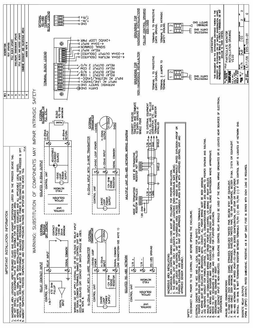
There are connections inside the control unit for the sensor coaxial cable, the power supply, relay contacts and optional 4-20mA or RS-485 outputs. Refer to the installation drawings.
Conduit openings are provided in the bottom of the enclosure to route wiring into the enclosure. Never drill new conduit openings in the side or top of the enclosure as a bad conduit seal may allow water to enter the enclosure.
Particulate Monitoring Systems Installation & Operating Manual
Document No. 210-1003-G Page 8 ©2005
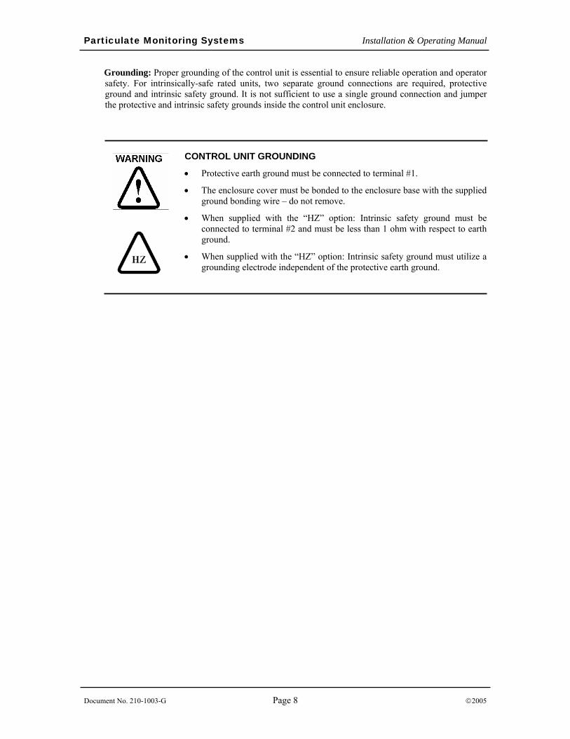
Grounding: Proper grounding of the control unit is essential to ensure reliable operation and operator safety. For intrinsically-safe rated units, two separate ground connections are required, protective ground and intrinsic safety ground. It is not sufficient to use a single ground connection and jumper the protective and intrinsic safety grounds inside the control unit enclosure.
CONTROL UNIT GROUNDING
• Protective earth ground must be connected to terminal #1.
• The enclosure cover must be bonded to the enclosure base with the supplied ground bonding wire – do not remove.
• When supplied with the “HZ” option: Intrinsic safety ground must be connected to terminal #2 and must be less than 1 ohm with respect to earth ground.
• When supplied with the “HZ” option: Intrinsic safety ground must utilize a grounding electrode independent of the protective earth ground.
Particulate Monitoring Systems Installation & Operating Manual
Document No. 210-1003-G Page 9 ©2005
7. Particulate Sensor Installation Location: The following factors should be considered when determining the sensor location:
Area Classification
Flow conditions
Electrical (Faraday) shielding
Atmospheric shielding (in the case of ducts and stacks open to atmosphere)
Access for installation and service
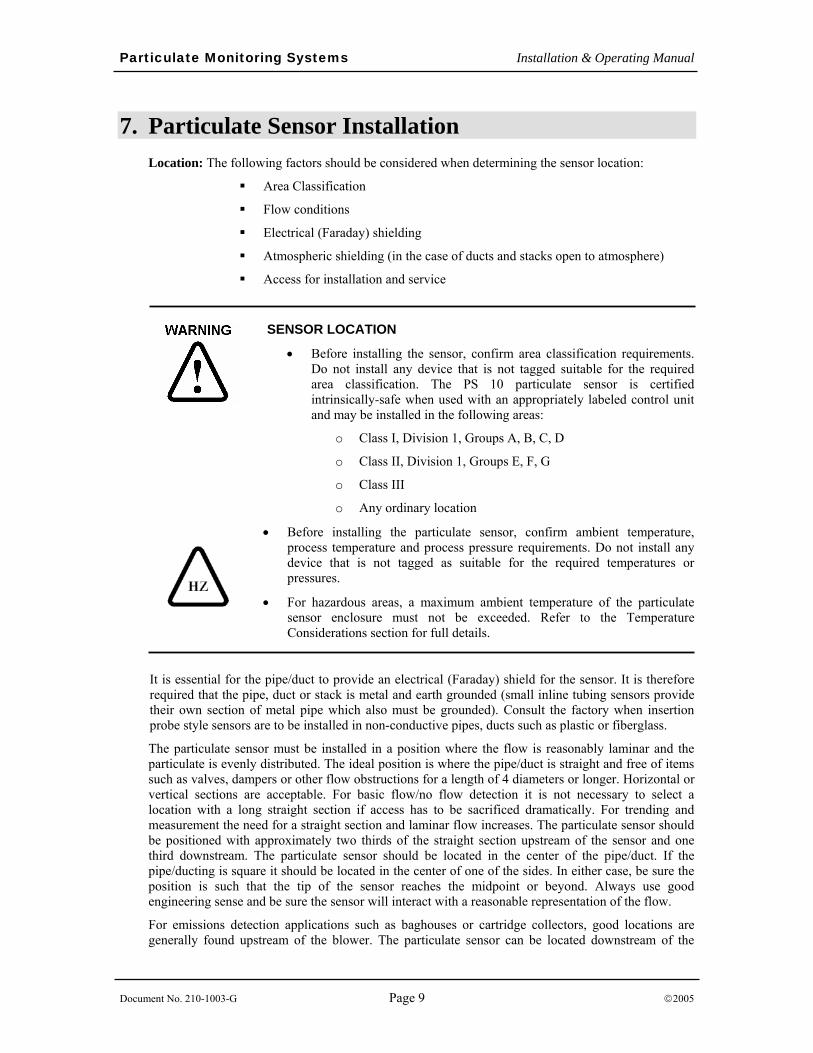
SENSOR LOCATION
• Before installing the sensor, confirm area classification requirements. Do not install any device that is not tagged suitable for the required area classification. The PS 10 particulate sensor is certified intrinsically-safe when used with an appropriately labeled control unit and may be installed in the following areas:
o Class I, Division 1, Groups A, B, C, D
o Class II, Division 1, Groups E, F, G
o Class III
o Any ordinary location
• Before installing the particulate sensor, confirm ambient temperature, process temperature and process pressure requirements. Do not install any device that is not tagged as suitable for the required temperatures or pressures.
• For hazardous areas, a maximum ambient temperature of the particulate sensor enclosure must not be exceeded. Refer to the Temperature Considerations section for full details.
It is essential for the pipe/duct to provide an electrical (Faraday) shield for the sensor. It is therefore required that the pipe, duct or stack is metal and earth grounded (small inline tubing sensors provide their own section of metal pipe which also must be grounded). Consult the factory when insertion probe style sensors are to be installed in non-conductive pipes, ducts such as plastic or fiberglass.
The particulate sensor must be installed in a position where the flow is reasonably laminar and the particulate is evenly distributed. The ideal position is where the pipe/duct is straight and free of items such as valves, dampers or other flow obstructions for a length of 4 diameters or longer. Horizontal or vertical sections are acceptable. For basic flow/no flow detection it is not necessary to select a location with a long straight section if access has to be sacrificed dramatically. For trending and measurement the need for a straight section and laminar flow increases. The particulate sensor should be positioned with approximately two thirds of the straight section upstream of the sensor and one third downstream. The particulate sensor should be located in the center of the pipe/duct. If the pipe/ducting is square it should be located in the center of one of the sides. In either case, be sure the position is such that the tip of the sensor reaches the midpoint or beyond. Always use good engineering sense and be sure the sensor will interact with a reasonable representation of the flow.
For emissions detection applications such as baghouses or cartridge collectors, good locations are generally found upstream of the blower. The particulate sensor can be located downstream of the
Particulate Monitoring Systems Installation & Operating Manual
Document No. 210-1003-G Page 10 ©2005
blower but not too close to the stack outlet. There must be sufficient duct downstream of the sensor to provide adequate electrical and atmospheric shielding. The sensor should be located upstream of any i sampling ports by at least two feet. It is not necessary that the sensor be in the same section of the duct/stack as the sampling ports. Particulate sampling ports require fully-developed laminar flow and longer straight sections.
Extreme vibration should be avoided.
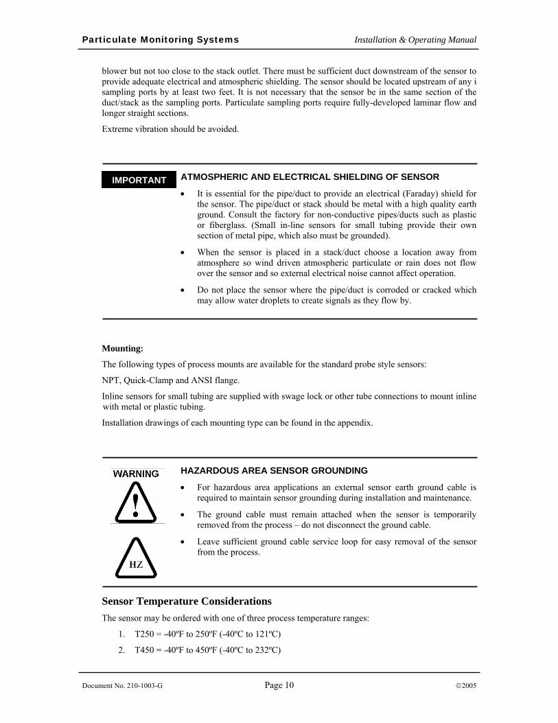
_ ATMOSPHERIC AND ELECTRICAL SHIELDING OF SENSOR
• It is essential for the pipe/duct to provide an electrical (Faraday) shield for the sensor. The pipe/duct or stack should be metal with a high quality earth ground. Consult the factory for non-conductive pipes/ducts such as plastic or fiberglass. (Small in-line sensors for small tubing provide their own section of metal pipe, which also must be grounded).
• When the sensor is placed in a stack/duct choose a location away from atmosphere so wind driven atmospheric particulate or rain does not flow over the sensor and so external electrical noise cannot affect operation.
• Do not place the sensor where the pipe/duct is corroded or cracked which may allow water droplets to create signals as they flow by.
Mounting:
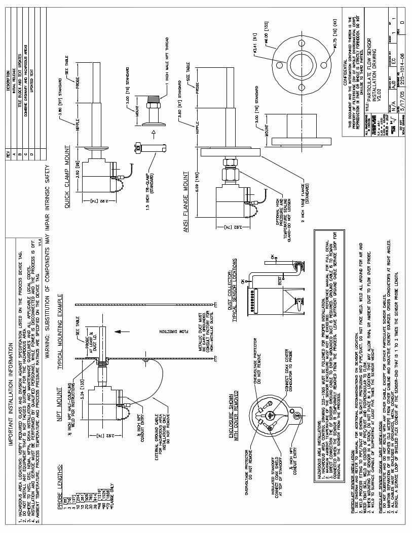
The following types of process mounts are available for the standard probe style sensors:
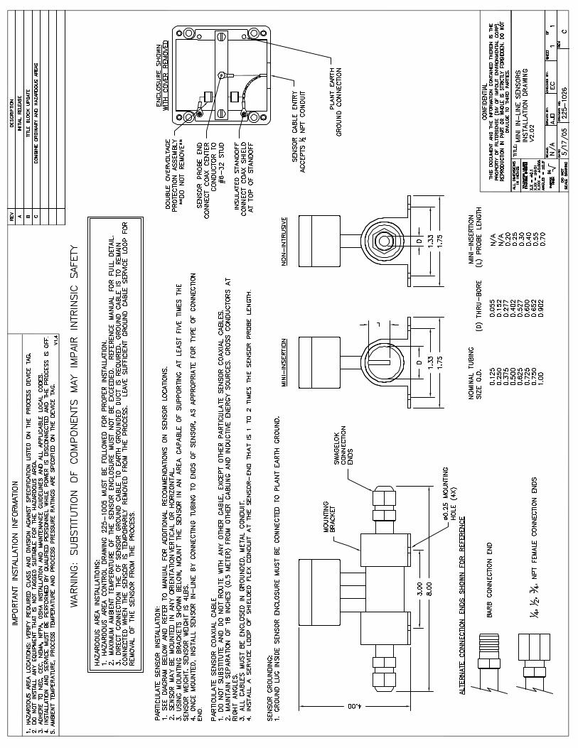
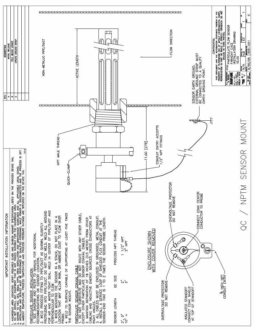
NPT, Quick-Clamp and ANSI flange.
Inline sensors for small tubing are supplied with swage lock or other tube connections to mount inline with metal or plastic tubing.
Installation drawings of each mounting type can be found in the appendix.
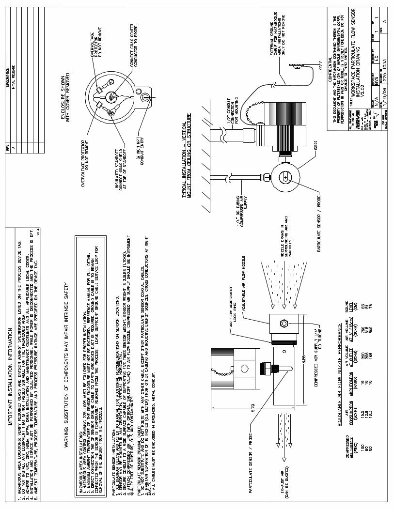
HAZARDOUS AREA SENSOR GROUNDING
• For hazardous area applications an external sensor earth ground cable is required to maintain sensor grounding during installation and maintenance.
• The ground cable must remain attached when the sensor is temporarily removed from the process – do not disconnect the ground cable.
• Leave sufficient ground cable service loop for easy removal of the sensor from the process.
Sensor Temperature Considerations The sensor may be ordered with one of three process temperature ranges:
1. T250 = -40ºF to 250ºF (-40ºC to 121ºC)
2. T450 = -40ºF to 450ºF (-40ºC to 232ºC)
IMPORTANT
Particulate Monitoring Systems Installation & Operating Manual
Document No. 210-1003-G Page 11 ©2005
3. T800 = -40ºF to 800ºF (-40ºC to 426ºC)
The maximum allowable internal temperature of the sensor housing, interior components and coaxial cable is 200ºC (392ºF). The internal temperature is influenced by:
1. The ambient air temperature around the enclosure.
2. The thermal transfer of heat from the process. This thermal transfer accounts for a 1ºC rise in internal enclosure temperature for every 10ºC the process temperature is above ambient.
The following WARNING applies to intrinsically safe rated units and the maximum allowable sensor ambient temperature:
MAXIMUM SENSOR AMBIENT TEMPERATURE FORMULA
The following formula should be used to calculate the maximum allowable sensor ambient temperature:
( )10
25200 CTEMPCTEMP PROCESSAMBIENT
°−−°= .
Where:
AMBIENTTEMP = Maximum Allowable Ambient Temperature (ºC)
PROCESSTEMP = Maximum Process Temperature (ºC)
Example Calculation 1: Sensor installed into a process running at a maximum temperature of 200ºC (392ºF):
( )10
25200200 CCCTEMPAMBIENT°−°
−°=
CCTEMPAMBIENT °−°= 5.17200
CTEMPAMBIENT °= 5.182
The maximum allowable ambient temperature for this process would be 182.5ºC (361ºF).
Example Calculation 2: Sensor installed into a process running at a maximum temperature of 426ºC (800ºF):
( )10
25426200 CCCTEMPAMBIENT°−°
−°=
CCTEMPAMBIENT °−°= 1.40200
CTEMPAMBIENT °= 9.159
The maximum allowable ambient temperature for this process would be 159.9ºC (320ºF).
Particulate Monitoring Systems Installation & Operating Manual
Document No. 210-1003-G Page 12 ©2005
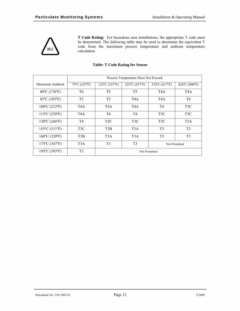
T Code Rating: For hazardous area installations, the appropriate T code must be determined. The following table may be used to determine the equivalent T code from the maximum process temperature and ambient temperature calculation
Table: T Code Rating for Sensor
Process Temperature Does Not Exceed
Maximum Ambient 75ºC (167ºF) 125ºC (257ºF) 225ºC (437ºF) 325ºC (617ºF) 426ºC (800ºF)
80ºC (176ºF) T6 T5 T5 T4A T4A
85ºC (185ºF) T5 T5 T4A T4A T4
100ºC (212ºF) T4A T4A T4A T4 T3C
115ºC (239ºF) T4A T4 T4 T3C T3C
130ºC (266ºF) T4 T3C T3C T3C T3A
155ºC (311ºF) T3C T3B T3A T3 T3
160ºC (320ºF) T3B T3A T3A T3 T3
175ºC (347ºF) T3A T3 T3 Not Permitted
195ºC (383ºF) T3 Not Permitted
Particulate Monitoring Systems Installation & Operating Manual
Document No. 210-1003-G Page 13 ©2005
8. Particulate Sensor Coaxial Cable Installation
Connection: Prior to making coaxial cable connections review the following routing instructions.
_ PARTICULATE SENSOR COAXIAL CABLE ROUTING
• The sensor cable must be installed in conduit that is separate from all other wiring.
• The cable should be routed from the particulate sensor to the control unit in a path that avoids high vibration, heat over 394°F (200°C) and any strong magnetic or electrical fields.
• The cable should be located at least 18 in (46 cm) away from any power lines (conduit), motors, frequency drives and other sources of electrical interference throughout its entire path.
• The cable should be installed in metallic conduit. At the process end, use a section of shielded flex conduit that is 1 to 2 times the probe length to serve as a service loop.
The coaxial cable is connected to the control unit by a coax connector and is connected to the sensor by two ring terminals. The connectors are normally supplied pre-assembled to the cable.
Once the cable has been routed, insert the coax connector into the control unit enclosure leaving a very small service loop as specified in the installation drawing shown in the appendix. A larger service loop should be used at the sensor end, typically 1 to 2 times the sensor length. Any small amount of extra cable length should be pulled into the nearest junction box and NOT left in the sensor housing or in the control unit enclosure. If there is a significant amount of extra cable (many feet), the cable should be shortened at the sensor end and the sensor end connectors should be re-assembled using factory-supplied connectors and instructions.
_ COAXIAL CABLE INSIDE THE CONTROL UNIT
• A ferrite suppressor is located on the sensor coaxial cable near the coax connector and must remain inside the control unit enclosure.
• The black cable insulation must extend a minimum of 6 in (15 cm) into the coax cable conduit.
• Do not leave any excess cable in the control unit or sensor housing.
Inside the particulate sensor enclosure, attach the coax cable as indicated in the sensor drawing. When connecting the braided shield, ensure it does not touch the surge voltage protection assembly. Do not leave excess cable inside the sensor housing.
IMPORTANT
IMPORTANT
Particulate Monitoring Systems Installation & Operating Manual
Document No. 210-1003-G Page 14 ©2005
Sensor Test Port (Non-Hazardous Areas Only) Location: A test port should be installed in a negative pressure location. It must be located upstream of the sensor so particulate can flow very near and around the sensor. It should be located at least 3 ft (1 m) upstream of the sensor and it should be located on the same side of the duct as the sensor so particles can pass very near and around the sensor. If possible locate the test port at ground level.
Mounting: The test port is either screwed into a 1/8 inch NPT threaded hole, or welded in position. (Note: A foot or so of tubing can be connected to the nipple to make it easy to draw particles out of a container. Only a pinch of particulate at a time is needed for a response check.)
_ TEST PORT INSTALLATION
• Installation of a sensor test port enables checking the response to an actual increase in particulate.
IMPORTANT
Particulate Monitoring Systems Installation & Operating Manual
Document No. 210-1003-G Page 15 ©2005
9. Control Unit Operation
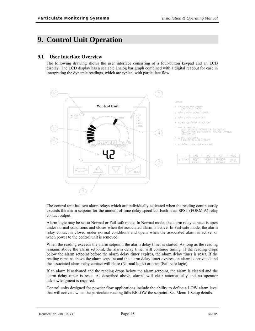
9.1 User Interface Overview The following drawing shows the user interface consisting of a four-button keypad and an LCD display. The LCD display has a scalable analog bar graph combined with a digital readout for ease in interpreting the dynamic readings, which are typical with particulate flow.
Control Unit
The control unit has two alarm relays which are individually activated when the reading continuously exceeds the alarm setpoint for the amount of time delay specified. Each is an SPST (FORM A) relay contact output.
Alarm logic may be set to Normal or Fail-safe mode. In Normal mode, the alarm relay contact is open under normal conditions and closes when the associated alarm is active. In Fail-safe mode, the alarm relay contact is closed under normal conditions and opens when the associated alarm is active, or when power to the control unit is removed.
When the reading exceeds the alarm setpoint, the alarm delay timer is started. As long as the reading remains above the alarm setpoint, the alarm delay timer will continue timing. If the reading drops below the alarm setpoint before the alarm delay timer expires, the alarm delay timer is reset. If the reading remains above the alarm setpoint and the alarm delay timer expires, an alarm is activated and the associated alarm relay contact will close (Normal logic) or open (Fail-safe logic).
If an alarm is activated and the reading drops below the alarm setpoint, the alarm is cleared and the alarm delay timer is reset. As described above, alarms will clear automatically and no operator acknowledgment is required.
Control units designed for powder flow applications include the ability to define a LOW alarm level that will activate when the particulate reading falls BELOW the setpoint. See Menu 1 Setup details.
Particulate Monitoring Systems Installation & Operating Manual
Document No. 210-1003-G Page 16 ©2005
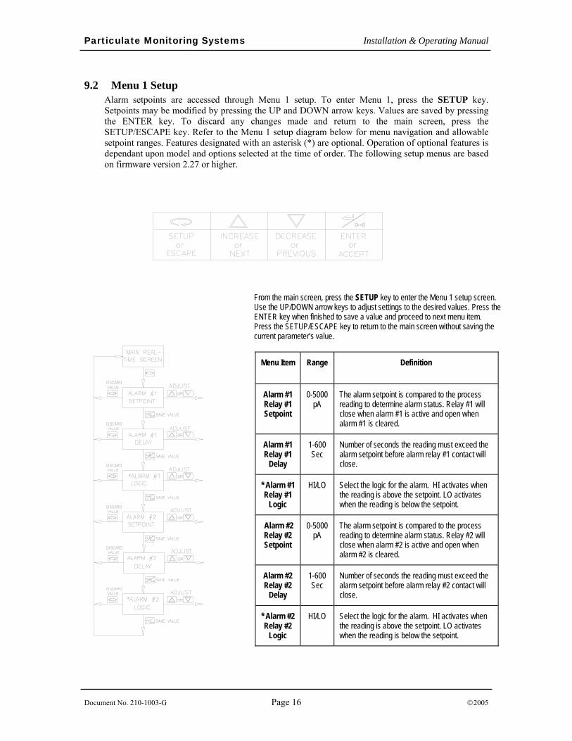
9.2 Menu 1 Setup Alarm setpoints are accessed through Menu 1 setup. To enter Menu 1, press the SETUP key. Setpoints may be modified by pressing the UP and DOWN arrow keys. Values are saved by pressing the ENTER key. To discard any changes made and return to the main screen, press the SETUP/ESCAPE key. Refer to the Menu 1 setup diagram below for menu navigation and allowable setpoint ranges. Features designated with an asterisk (*) are optional. Operation of optional features is dependant upon model and options selected at the time of order. The following setup menus are based on firmware version 2.27 or higher.
From the main screen, press the SETUP key to enter the Menu 1 setup screen. Use the UP/DOWN arrow keys to adjust settings to the desired values. Press the ENTER key when finished to save a value and proceed to next menu item. Press the SETUP/ESCAPE key to return to the main screen without saving the current parameter’s value.
Menu Item Range Definition
Alarm #1 Relay #1 Setpoint
0-5000 pA
The alarm setpoint is compared to the process reading to determine alarm status. Relay #1 will close when alarm #1 is active and open when alarm #1 is cleared.
Alarm #1 Relay #1
Delay
1-600 Sec
Number of seconds the reading must exceed the alarm setpoint before alarm relay #1 contact will close.
* Alarm #1 Relay #1
Logic
HI/LO Select the logic for the alarm. HI activates when the reading is above the setpoint. LO activates when the reading is below the setpoint.
Alarm #2 Relay #2 Setpoint
0-5000 pA
The alarm setpoint is compared to the process reading to determine alarm status. Relay #2 will close when alarm #2 is active and open when alarm #2 is cleared.
Alarm #2 Relay #2
Delay
1-600 Sec
Number of seconds the reading must exceed the alarm setpoint before alarm relay #2 contact will close.
* Alarm #2 Relay #2
Logic
HI/LO Select the logic for the alarm. HI activates when the reading is above the setpoint. LO activates when the reading is below the setpoint.
Particulate Monitoring Systems Installation & Operating Manual
Document No. 210-1003-G Page 17 ©2005
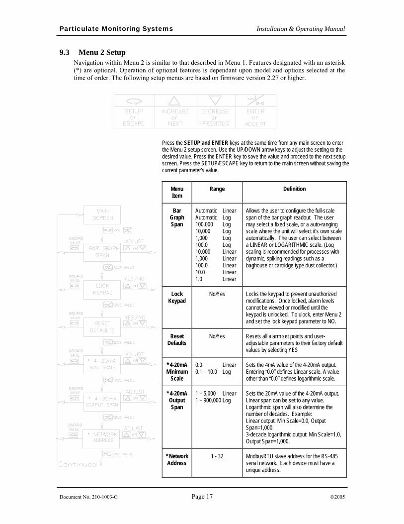
9.3 Menu 2 Setup Navigation within Menu 2 is similar to that described in Menu 1. Features designated with an asterisk (*) are optional. Operation of optional features is dependant upon model and options selected at the time of order. The following setup menus are based on firmware version 2.27 or higher.
Press the SETUP and ENTER keys at the same time from any main screen to enter the Menu 2 setup screen. Use the UP/DOWN arrow keys to adjust the setting to the desired value. Press the ENTER key to save the value and proceed to the next setup screen. Press the SETUP/ESCAPE key to return to the main screen without saving the current parameter’s value.
Menu Item
Range Definition
Bar Graph Span
Automatic Linear Automatic Log 100,000 Log 10,000 Log 1,000 Log 100.0 Log 10,000 Linear 1,000 Linear 100.0 Linear 10.0 Linear 1.0 Linear
Allows the user to configure the full-scale span of the bar graph readout. The user may select a fixed scale, or a auto-ranging scale where the unit will select it’s own scale automatically. The user can select between a LINEAR or LOGARITHMIC scale. (Log scaling is recommended for processes with dynamic, spiking readings such as a baghouse or cartridge type dust collector.)
Lock Keypad
No/Yes Locks the keypad to prevent unauthorized modifications. Once locked, alarm levels cannot be viewed or modified until the keypad is unlocked. To ulock, enter Menu 2 and set the lock keypad parameter to NO.
Reset Defaults
No/Yes Resets all alarm set points and user-adjustable parameters to their factory default values by selecting YES
* 4-20mA Minimum
Scale
0.0 Linear 0.1 – 10.0 Log
Sets the 4mA value of the 4-20mA output. Entering “0.0” defines Linear scale. A value other than “0.0” defines logarithmic scale.
* 4-20mA Output Span
1 – 5,000 Linear 1 – 900,000 Log
Sets the 20mA value of the 4-20mA output. Linear span can be set to any value. Logarithmic span will also determine the number of decades. Example: Linear output: Min Scale=0.0, Output Span=1,000. 3-decade logarithmic output: Min Scale=1.0, Output Span=1,000.
* Network Address
1 - 32 ModbusRTU slave address for the RS-485 serial network. Each device must have a unique address.
Particulate Monitoring Systems Installation & Operating Manual
Document No. 210-1003-G Page 18 ©2005
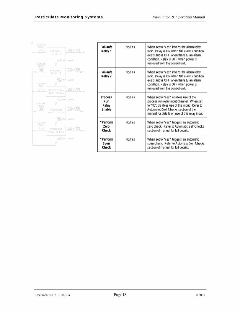
Fail-safe Relay 1
No/Yes When set to “Yes”, inverts the alarm relay logic. Relay is ON when NO alarm condition exists and is OFF when there IS an alarm condition. Relay is OFF when power is removed from the control unit.
Fail-safe Relay 2
No/Yes When set to “Yes”, inverts the alarm relay logic. Relay is ON when NO alarm condition exists and is OFF when there IS an alarm condition. Relay is OFF when power is removed from the control unit.
Process Run
Relay Enable
No/Yes When set to “Yes”, enables use of the process run relay input channel. When set to “No”, disables use of this input. Refer to Automated Self Checks section of the manual for details on use of this relay input.
* Perform Zero
Check
No/Yes When set to “Yes”, triggers an automatic zero check. Refer to Automatic Self Checks section of manual for full details.
* Perform Span Check
No/Yes When set to “Yes”, triggers an automatic span check. Refer to Automatic Self Checks section of manual for full details.
Particulate Monitoring Systems Installation & Operating Manual
Document No. 210-1003-G Page 19 ©2005
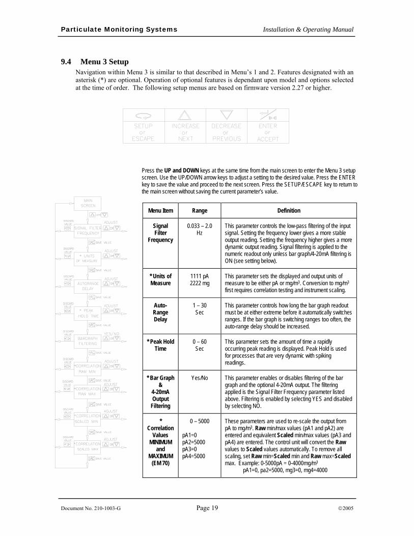
9.4 Menu 3 Setup Navigation within Menu 3 is similar to that described in Menu’s 1 and 2. Features designated with an asterisk (*) are optional. Operation of optional features is dependant upon model and options selected at the time of order. The following setup menus are based on firmware version 2.27 or higher.
Press the UP and DOWN keys at the same time from the main screen to enter the Menu 3 setup screen. Use the UP/DOWN arrow keys to adjust a setting to the desired value. Press the ENTER key to save the value and proceed to the next screen. Press the SETUP/ESCAPE key to return to the main screen without saving the current parameter’s value.
Menu Item Range Definition
Signal Filter
Frequency
0.033 – 2.0 Hz
This parameter controls the low-pass filtering of the input signal. Setting the frequency lower gives a more stable output reading. Setting the frequency higher gives a more dynamic output reading. Signal filtering is applied to the numeric readout only unless bar graph/4-20mA filtering is ON (see setting below).
* Units of Measure
1111 pA 2222 mg
This parameter sets the displayed and output units of measure to be either pA or mg/m3. Conversion to mg/m3
first requires correlation testing and instrument scaling.
Auto-Range Delay
1 – 30 Sec
This parameter controls how long the bar graph readout must be at either extreme before it automatically switches ranges. If the bar graph is switching ranges too often, the auto-range delay should be increased.
* Peak Hold Time
0 – 60 Sec
This parameter sets the amount of time a rapidly occurring peak reading is displayed. Peak Hold is used for processes that are very dynamic with spiking readings.
* Bar Graph &
4-20mA Output
Filtering
Yes/No This parameter enables or disables filtering of the bar graph and the optional 4-20mA output. The filtering applied is the Signal Filter Frequency parameter listed above. Filtering is enabled by selecting YES and disabled by selecting NO.
* Correlation
Values MINIMUM
and MAXIMUM
(EM 70)
0 – 5000
pA1=0 pA2=5000 pA3=0 pA4=5000
These parameters are used to re-scale the output from pA to mg/m3. Raw min/max values (pA1 and pA2) are entered and equivalent Scaled min/max values (pA3 and pA4) are entered. The control unit will convert the Raw values to Scaled values automatically. To remove all scaling, set Raw min=Scaled min and Raw max=Scaled max. Example: 0-5000pA = 0-4000mg/m3 pA1=0, pa2=5000, mg3=0, mg4=4000
Particulate Monitoring Systems Installation & Operating Manual
Document No. 210-1003-G Page 20 ©2005
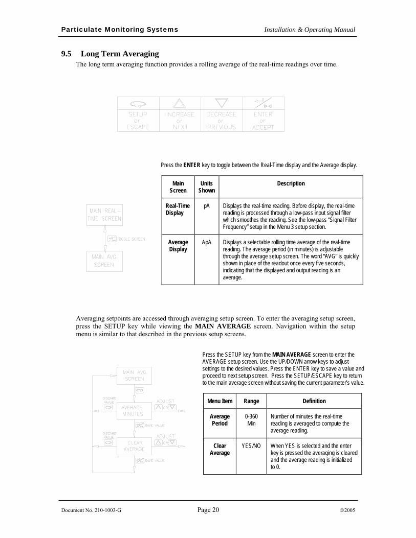
9.5 Long Term Averaging The long term averaging function provides a rolling average of the real-time readings over time.
Averaging setpoints are accessed through averaging setup screen. To enter the averaging setup screen, press the SETUP key while viewing the MAIN AVERAGE screen. Navigation within the setup menu is similar to that described in the previous setup screens.
Press the SETUP key from the MAIN AVERAGE screen to enter the AVERAGE setup screen. Use the UP/DOWN arrow keys to adjust settings to the desired values. Press the ENTER key to save a value and proceed to next setup screen. Press the SETUP/ESCAPE key to return to the main average screen without saving the current parameter’s value.
Menu Item Range Definition
Average Period
0-360 Min
Number of minutes the real-time reading is averaged to compute the average reading.
Clear Average
YES/NO When YES is selected and the enter key is pressed the averaging is cleared and the average reading is initialized to 0.
Press the ENTER key to toggle between the Real-Time display and the Average display.
Main Screen
Units Shown
Description
Real-Time Display
pA Displays the real-time reading. Before display, the real-time reading is processed through a low-pass input signal filter which smoothes the reading. See the low-pass “Signal Filter Frequency” setup in the Menu 3 setup section.
Average Display
ApA Displays a selectable rolling time average of the real-time reading. The average period (in minutes) is adjustable through the average setup screen. The word “AVG” is quickly shown in place of the readout once every five seconds, indicating that the displayed and output reading is an average.
Particulate Monitoring Systems Installation & Operating Manual
Document No. 210-1003-G Page 21 ©2005
9.6 4-20mA Analog Output Scaling Particulate levels may be transmitted to external devices with the 4-20mA analog output. Typical applications include remote monitoring of particulate levels with a PLC, chart recorder or panel meter. The 4-20mA output is transmitted as linear or multi-decade logarithmic output.
Two parameters determine the type of output signal. The “4-20mA Minimum Scale” parameter determines the pA equivalent of the 4mA output. Setting this parameter to “0.0” enables the Linear scale. A value other than “0.0” initiates Logarithmic scale. The “4-20mA Output Span” parameter determines the pA equivalent of the 20 mA output.
The 4-20mA analog output represents the linear or logarithmic equivalent of the “pA” particulate levels. Once the analog output has been transmitted to the PLC or chart recorder, it is recommended to convert the 4-20mA signal back into pA to assist in data interpretation, alarm level determination and historical data comparison. This can be of particular importance for EPA regulatory applications. The following two examples show the formulas used to convert the 4-20mA signal into pA.
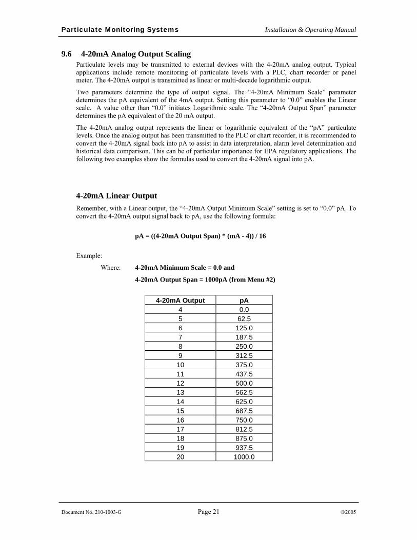
4-20mA Linear Output Remember, with a Linear output, the “4-20mA Output Minimum Scale” setting is set to “0.0” pA. To convert the 4-20mA output signal back to pA, use the following formula:
pA = ((4-20mA Output Span) * (mA - 4)) / 16
Example:
Where: 4-20mA Minimum Scale = 0.0 and
4-20mA Output Span = 1000pA (from Menu #2)
4-20mA Output pA
4 0.0 5 62.5 6 125.0 7 187.5 8 250.0 9 312.5
10 375.0 11 437.5 12 500.0 13 562.5 14 625.0 15 687.5 16 750.0 17 812.5 18 875.0 19 937.5 20 1000.0
Particulate Monitoring Systems Installation & Operating Manual
Document No. 210-1003-G Page 22 ©2005
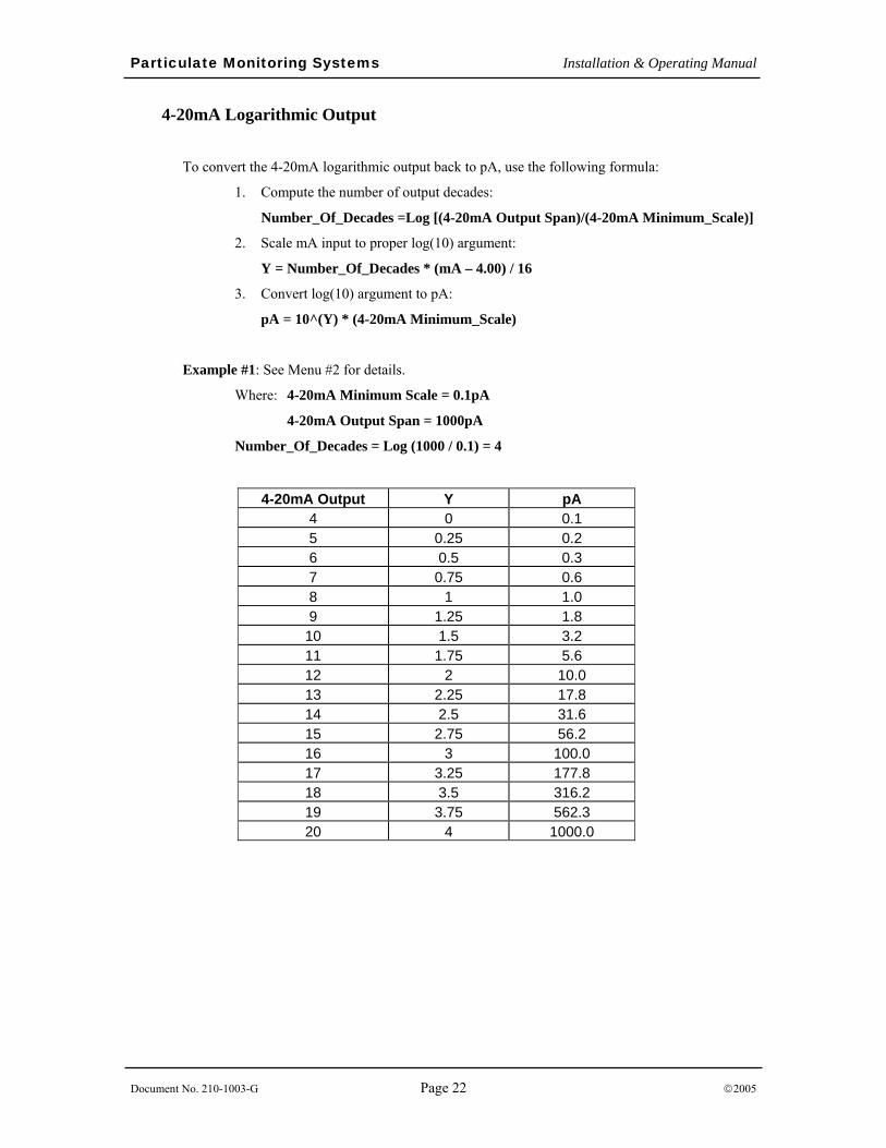
4-20mA Logarithmic Output
To convert the 4-20mA logarithmic output back to pA, use the following formula:
1. Compute the number of output decades:
Number_Of_Decades =Log [(4-20mA Output Span)/(4-20mA Minimum_Scale)]
2. Scale mA input to proper log(10) argument:
Y = Number_Of_Decades * (mA – 4.00) / 16
3. Convert log(10) argument to pA:
pA = 10^(Y) * (4-20mA Minimum_Scale)
Example #1: See Menu #2 for details.
Where: 4-20mA Minimum Scale = 0.1pA
4-20mA Output Span = 1000pA
Number_Of_Decades = Log (1000 / 0.1) = 4
4-20mA Output Y pA 4 0 0.1 5 0.25 0.2 6 0.5 0.3 7 0.75 0.6 8 1 1.0 9 1.25 1.8
10 1.5 3.2 11 1.75 5.6 12 2 10.0 13 2.25 17.8 14 2.5 31.6 15 2.75 56.2 16 3 100.0 17 3.25 177.8 18 3.5 316.2 19 3.75 562.3 20 4 1000.0
Particulate Monitoring Systems Installation & Operating Manual
Document No. 210-1003-G Page 23 ©2005
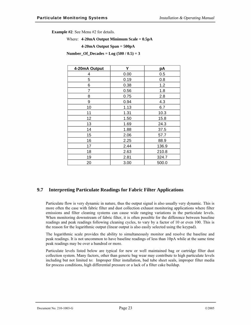
Example #2: See Menu #2 for details.
Where: 4-20mA Output Minimum Scale = 0.5pA
4-20mA Output Span = 500pA
Number_Of_Decades = Log (500 / 0.5) = 3
4-20mA Output Y pA 4 0.00 0.5 5 0.19 0.8 6 0.38 1.2 7 0.56 1.8 8 0.75 2.8 9 0.94 4.3
10 1.13 6.7 11 1.31 10.3 12 1.50 15.8 13 1.69 24.3 14 1.88 37.5 15 2.06 57.7 16 2.25 88.9 17 2.44 136.9 18 2.63 210.8 19 2.81 324.7 20 3.00 500.0
9.7 Interpreting Particulate Readings for Fabric Filter Applications
Particulate flow is very dynamic in nature, thus the output signal is also usually very dynamic. This is more often the case with fabric filter and dust collection exhaust monitoring applications where filter emissions and filter cleaning systems can cause wide ranging variations in the particulate levels. When monitoring downstream of fabric filter, it is often possible for the difference between baseline readings and peak readings following cleaning cycles, to vary by a factor of 10 or even 100. This is the reason for the logarithmic output (linear output is also easily selected using the keypad).
The logarithmic scale provides the ability to simultaneously monitor and resolve the baseline and peak readings. It is not uncommon to have baseline readings of less than 10pA while at the same time peak readings may be over a hundred or more.
Particulate levels listed below are typical for new or well maintained bag or cartridge filter dust collection system. Many factors, other than generic bag wear may contribute to high particulate levels including but not limited to: Improper filter installation, bad tube sheet seals, improper filter media for process conditions, high differential pressure or a lack of a filter cake buildup.
Particulate Monitoring Systems Installation & Operating Manual
Document No. 210-1003-G Page 24 ©2005
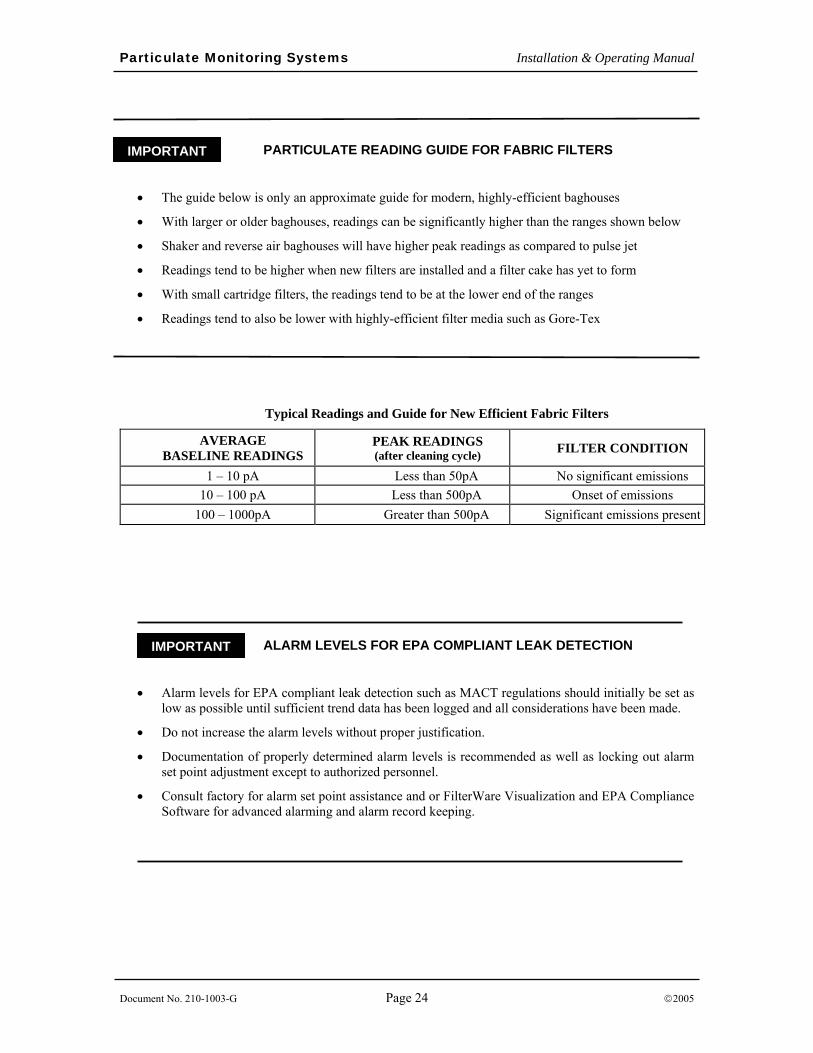
PARTICULATE READING GUIDE FOR FABRIC FILTERS
• The guide below is only an approximate guide for modern, highly-efficient baghouses
• With larger or older baghouses, readings can be significantly higher than the ranges shown below
• Shaker and reverse air baghouses will have higher peak readings as compared to pulse jet
• Readings tend to be higher when new filters are installed and a filter cake has yet to form
• With small cartridge filters, the readings tend to be at the lower end of the ranges
• Readings tend to also be lower with highly-efficient filter media such as Gore-Tex
_ ALARM LEVELS FOR EPA COMPLIANT LEAK DETECTION
• Alarm levels for EPA compliant leak detection such as MACT regulations should initially be set as low as possible until sufficient trend data has been logged and all considerations have been made.
• Do not increase the alarm levels without proper justification.
• Documentation of properly determined alarm levels is recommended as well as locking out alarm set point adjustment except to authorized personnel.
• Consult factory for alarm set point assistance and or FilterWare Visualization and EPA Compliance Software for advanced alarming and alarm record keeping.
Typical Readings and Guide for New Efficient Fabric Filters
AVERAGE BASELINE READINGS
PEAK READINGS (after cleaning cycle) FILTER CONDITION
1 – 10 pA Less than 50pA No significant emissions 10 – 100 pA Less than 500pA Onset of emissions
100 – 1000pA Greater than 500pA Significant emissions present
IMPORTANT
IMPORTANT
Particulate Monitoring Systems Installation & Operating Manual
Document No. 210-1003-G Page 25 ©2005
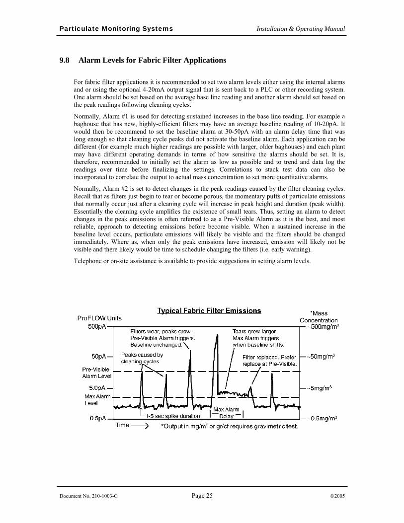
9.8 Alarm Levels for Fabric Filter Applications
For fabric filter applications it is recommended to set two alarm levels either using the internal alarms and or using the optional 4-20mA output signal that is sent back to a PLC or other recording system. One alarm should be set based on the average base line reading and another alarm should set based on the peak readings following cleaning cycles.
Normally, Alarm #1 is used for detecting sustained increases in the base line reading. For example a baghouse that has new, highly-efficient filters may have an average baseline reading of 10-20pA. It would then be recommend to set the baseline alarm at 30-50pA with an alarm delay time that was long enough so that cleaning cycle peaks did not activate the baseline alarm. Each application can be different (for example much higher readings are possible with larger, older baghouses) and each plant may have different operating demands in terms of how sensitive the alarms should be set. It is, therefore, recommended to initially set the alarm as low as possible and to trend and data log the readings over time before finalizing the settings. Correlations to stack test data can also be incorporated to correlate the output to actual mass concentration to set more quantitative alarms.
Normally, Alarm #2 is set to detect changes in the peak readings caused by the filter cleaning cycles. Recall that as filters just begin to tear or become porous, the momentary puffs of particulate emissions that normally occur just after a cleaning cycle will increase in peak height and duration (peak width). Essentially the cleaning cycle amplifies the existence of small tears. Thus, setting an alarm to detect changes in the peak emissions is often referred to as a Pre-Visible Alarm as it is the best, and most reliable, approach to detecting emissions before become visible. When a sustained increase in the baseline level occurs, particulate emissions will likely be visible and the filters should be changed immediately. Where as, when only the peak emissions have increased, emission will likely not be visible and there likely would be time to schedule changing the filters (i.e. early warning).
Telephone or on-site assistance is available to provide suggestions in setting alarm levels.
Particulate Monitoring Systems Installation & Operating Manual
Document No. 210-1003-G Page 26 ©2005
10. Manual System Zero Check The System Zero Check is used at installation to confirm proper installation and for troubleshooting. This check is mostly for control units that are not equipped with the optional self check subsystem.
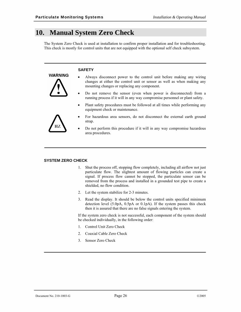
SAFETY
• Always disconnect power to the control unit before making any wiring changes at either the control unit or sensor as well as when making any mounting changes or replacing any component.
• Do not remove the sensor (even when power is disconnected) from a running process if it will in any way compromise personnel or plant safety.
• Plant safety procedures must be followed at all times while performing any equipment check or maintenance.
• For hazardous area sensors, do not disconnect the external earth ground strap.
• Do not perform this procedure if it will in any way compromise hazardous area procedures.
SYSTEM ZERO CHECK
1. Shut the process off, stopping flow completely, including all airflow not just particulate flow. The slightest amount of flowing particles can create a signal. If process flow cannot be stopped, the particulate sensor can be removed from the process and installed in a grounded test pipe to create a shielded, no flow condition.
2. Let the system stabilize for 2-3 minutes.
3. Read the display. It should be below the control units specified minimum detection level (5.0pA, 0.5pA or 0.1pA). If the system passes this check then it is assured that there are no false signals entering the system.
If the system zero check is not successful, each component of the system should be checked individually, in the following order:
1. Control Unit Zero Check
2. Coaxial Cable Zero Check
3. Sensor Zero Check
Particulate Monitoring Systems Installation & Operating Manual
Document No. 210-1003-G Page 27 ©2005
CONTROL UNIT ZERO CHECK 1. Disconnect power to the control unit.
2. Open the enclosure cover and unscrew the coaxial cable connector from the control unit. Leave the connector inside the control unit enclosure. Make sure the connector does not slip down into the conduit.
3. Close the control unit enclosure cover.
4. Re-apply power to the control unit and allow the reading to stabilize for 1-2 minutes.
5. Read the display. It should be below the control units specified minimum detection level (5.0pA, 0.5pA or 0.1pA). If the control unit passes this check, there are no false signals entering the control unit.
PASS:
1. Disconnect power from the control unit.
2. Open the enclosure cover and re-attach the coaxial cable connector to the control unit.
3. Close the enclosure cover and proceed to the Coaxial Cable Zero Check.
FAIL:
1. If a zero reading cannot be obtained, close the enclosure cover and contact the factory for further assistance.
COAXIAL CABLE ZERO CHECK
1. Disconnect power to the control unit.
2. Open the sensor enclosure cover and disconnect the coaxial cable center conductor from the sensor probe end. Do not disconnect the coaxial cable shield. Do not remove the probe from the process. Leave the coaxial cable center conductor ring terminal hanging in free space within the sensor enclosure (do not isolate it with tape) and close the cover.
3. Re-apply power to the control unit and allow the reading to stabilize for 1-2 minutes.
4. Read the display. It should be below the control units specified minimum detection level (5.0pA, 0.5pA or 0.1pA). If the coaxial cable passes this check then there are no false signals entering the coaxial cable.
PASS:
1. Disconnect power to the control unit.
2. Open the sensor enclosure cover and re-attach the coaxial cable center conductor to the sensor probe end.
3. Close the sensor enclosure cover and proceed to the sensor zero check.
FAIL:
1. Check cable installation and routing instructions in the Installation section of this manual for proper cable installation. Make any changes necessary.
2. Contact the factory for further assistance.
Particulate Monitoring Systems Installation & Operating Manual
Document No. 210-1003-G Page 28 ©2005
Once the control unit and coaxial cable zero have been checked, proceed to the Sensor Zero Check. To perform the sensor zero check the process flow must be stopped or a sensor test pipe (available from Factory) or length of metal pipe will be needed (4”-6” diameter pipe or larger). The pipe should be at least 3 in (8 cm) longer than the probe itself and must be grounded. The length of pipe will serve as an electrical shield for the probe while it is out of the process.
SENSOR ZERO CHECK
1. Do not remove the sensor from a running process if it will in any way compromise personnel, plant safety or hazardous area safety procedures.
2. Disconnect power to the control unit.
3. Remove the sensor from the process and insert it into the grounded metal test pipe. For hazardous area sensors do not disconnect the external sensor earth ground strap.
4. Re-apply power to the control unit and allow the reading to stabilize for 1-2 minutes.
5. Read the display. It should be below the control units specified minimum detection level (5.0pA, 0.5pA or 0.1pA). If the sensor passes this check there are no false signals from the sensor.
PASS:
1. Disconnect power to the control unit.
2. Remove the sensor from the grounded test pipe and re-insert into the process. For hazardous area sensors do not disconnect the external sensor ground strap.
FAIL:
1. Contact the factory for further assistance.
When performing a zero check, keep in mind that it may be acceptable to consider a small false signal negligible. For example if the baseline readings are 100pA and a system zero offset of 1pA was found, this is only a 1% affect on the normal readings. If using the device for basic flow/no flow detection or basic emissions detection, this would not be significant.
Particulate Monitoring Systems Installation & Operating Manual
Document No. 210-1003-G Page 29 ©2005
11. Automatic Self Checks An optional self check subsystem is available to automatically verify calibration and proper operation of the electronics, sensor and cable. Self checks can be performed while the system is online and monitoring particulate. No external test equipment or operator intervention is required to activate or complete the self check routines. Any errors detected by the self checks are reported through the display, 4-20mA, relay and Modbus outputs. The following automatic self checks are performed:
• Control Unit Hardware Check
• Control Unit Calibration (Zero and Span)
• Sensor Cable Check
• Particulate Sensor/Probe Check
The control unit zero and span self checks that are performed meet all requirements of the EPA MACT Quality Assurance specifications. Self checks may be activated manually through the control unit keypad or on a continuous basis at pre-defined time periods. Information regarding the results of the most-recently performed self checks is stored in the control unit’s non-volatile memory and will be maintained even with loss of control unit power.
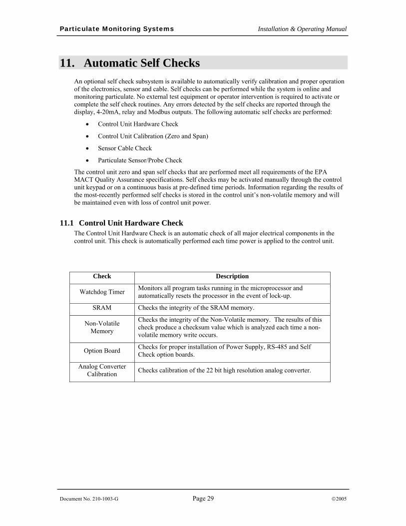
11.1 Control Unit Hardware Check The Control Unit Hardware Check is an automatic check of all major electrical components in the control unit. This check is automatically performed each time power is applied to the control unit.
Check Description
Watchdog Timer Monitors all program tasks running in the microprocessor and automatically resets the processor in the event of lock-up.
SRAM Checks the integrity of the SRAM memory.
Non-Volatile Memory
Checks the integrity of the Non-Volatile memory. The results of this check produce a checksum value which is analyzed each time a non-volatile memory write occurs.
Option Board Checks for proper installation of Power Supply, RS-485 and Self Check option boards.
Analog Converter Calibration Checks calibration of the 22 bit high resolution analog converter.
Particulate Monitoring Systems Installation & Operating Manual
Document No. 210-1003-G Page 30 ©2005
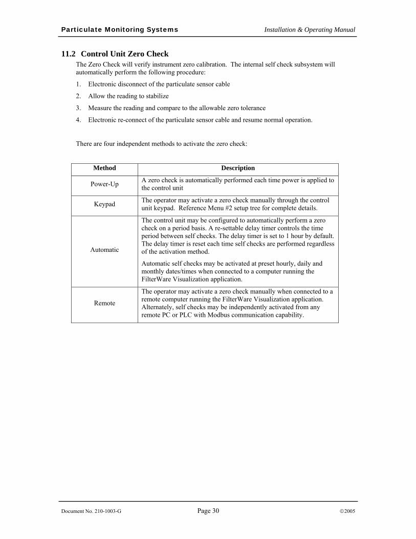
11.2 Control Unit Zero Check The Zero Check will verify instrument zero calibration. The internal self check subsystem will automatically perform the following procedure:
1. Electronic disconnect of the particulate sensor cable
2. Allow the reading to stabilize
3. Measure the reading and compare to the allowable zero tolerance
4. Electronic re-connect of the particulate sensor cable and resume normal operation.
There are four independent methods to activate the zero check:
Method Description
Power-Up A zero check is automatically performed each time power is applied to the control unit
Keypad The operator may activate a zero check manually through the control unit keypad. Reference Menu #2 setup tree for complete details.
Automatic
The control unit may be configured to automatically perform a zero check on a period basis. A re-settable delay timer controls the time period between self checks. The delay timer is set to 1 hour by default. The delay timer is reset each time self checks are performed regardless of the activation method.
Automatic self checks may be activated at preset hourly, daily and monthly dates/times when connected to a computer running the FilterWare Visualization application.
Remote
The operator may activate a zero check manually when connected to a remote computer running the FilterWare Visualization application. Alternately, self checks may be independently activated from any remote PC or PLC with Modbus communication capability.
Particulate Monitoring Systems Installation & Operating Manual
Document No. 210-1003-G Page 31 ©2005
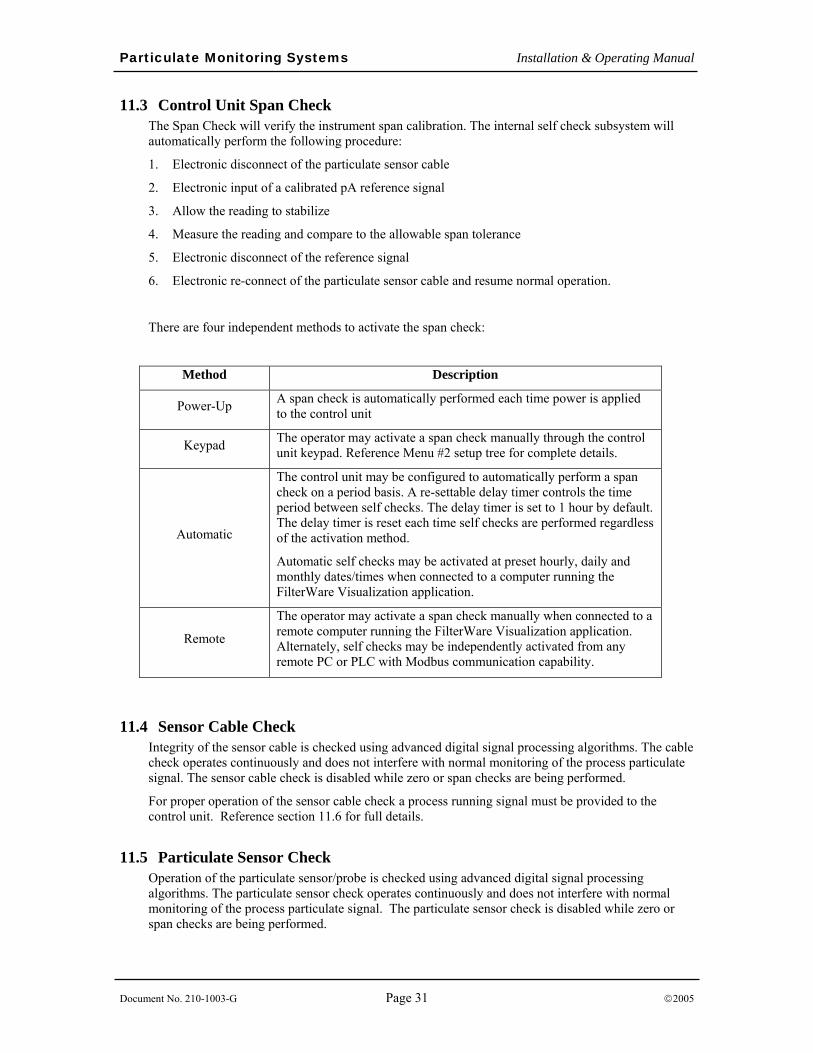
11.3 Control Unit Span Check The Span Check will verify the instrument span calibration. The internal self check subsystem will automatically perform the following procedure:
1. Electronic disconnect of the particulate sensor cable
2. Electronic input of a calibrated pA reference signal
3. Allow the reading to stabilize
4. Measure the reading and compare to the allowable span tolerance
5. Electronic disconnect of the reference signal
6. Electronic re-connect of the particulate sensor cable and resume normal operation.
There are four independent methods to activate the span check:
Method Description
Power-Up A span check is automatically performed each time power is applied to the control unit
Keypad The operator may activate a span check manually through the control unit keypad. Reference Menu #2 setup tree for complete details.
Automatic
The control unit may be configured to automatically perform a span check on a period basis. A re-settable delay timer controls the time period between self checks. The delay timer is set to 1 hour by default. The delay timer is reset each time self checks are performed regardless of the activation method.
Automatic self checks may be activated at preset hourly, daily and monthly dates/times when connected to a computer running the FilterWare Visualization application.
Remote
The operator may activate a span check manually when connected to a remote computer running the FilterWare Visualization application. Alternately, self checks may be independently activated from any remote PC or PLC with Modbus communication capability.
11.4 Sensor Cable Check Integrity of the sensor cable is checked using advanced digital signal processing algorithms. The cable check operates continuously and does not interfere with normal monitoring of the process particulate signal. The sensor cable check is disabled while zero or span checks are being performed.
For proper operation of the sensor cable check a process running signal must be provided to the control unit. Reference section 11.6 for full details.
11.5 Particulate Sensor Check Operation of the particulate sensor/probe is checked using advanced digital signal processing algorithms. The particulate sensor check operates continuously and does not interfere with normal monitoring of the process particulate signal. The particulate sensor check is disabled while zero or span checks are being performed.
Particulate Monitoring Systems Installation & Operating Manual
Document No. 210-1003-G Page 32 ©2005
11.6 Process Running Signal A process running signal indicates to the control unit whether the main process fan is ON or OFF. Connection of a process running signal adds the following capabilities to the automatic self check subsystem:
1. Sensor cable check – reference section 11.4 for further details.
2. Automatic system zero – verifies zero of the total system electronics, cable and sensor while fully installed in the process.
For proper operation the following conditions must be met:
1. A process running signal must be connected to the control unit process run relay input channel. This signal must be provided from an isolated, non-powered relay contact that closes when the main process fan is on, and opens when the main process fan is off. A motor starter auxiliary contact and/or separate control relay are typically used to provide this signal to the control unit. Refer to the installation drawings for details on making connections to the relay input channel.
2. The process run relay input channel must be enabled for use. Reference menu #2 setup tree for complete details.
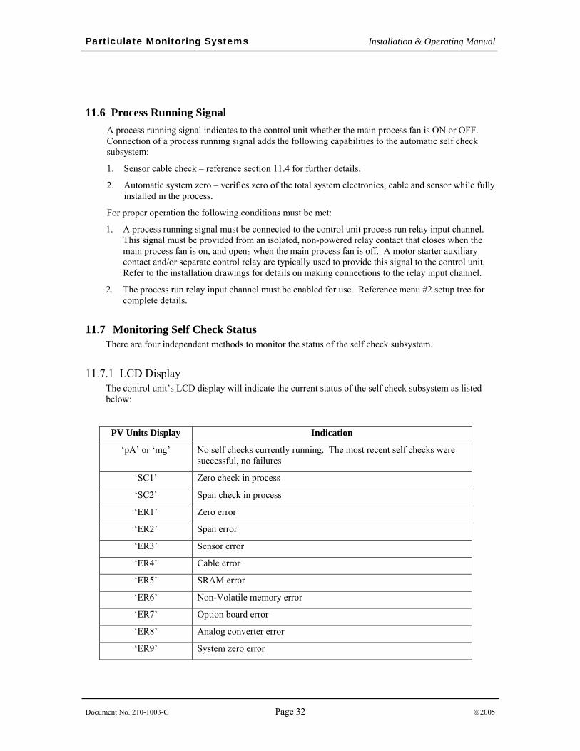
11.7 Monitoring Self Check Status There are four independent methods to monitor the status of the self check subsystem.
11.7.1 LCD Display The control unit’s LCD display will indicate the current status of the self check subsystem as listed below:
PV Units Display Indication
‘pA’ or ‘mg’ No self checks currently running. The most recent self checks were successful, no failures
‘SC1’ Zero check in process
‘SC2’ Span check in process
‘ER1’ Zero error
‘ER2’ Span error
‘ER3’ Sensor error
‘ER4’ Cable error
‘ER5’ SRAM error
‘ER6’ Non-Volatile memory error
‘ER7’ Option board error
‘ER8’ Analog converter error
‘ER9’ System zero error
Particulate Monitoring Systems Installation & Operating Manual
Document No. 210-1003-G Page 33 ©2005
11.7.2 Alarm Relay An alarm output relay can be activated if any self checks are unsuccessful. The alarm relay will remain activated until a subsequent self check is performed successfully, or power to the control unit is disconnected. Alarm relay #1 will be activated in the event of a self check failure by default. Alarm output relays may be configured to operate in normal or fail-safe modes.
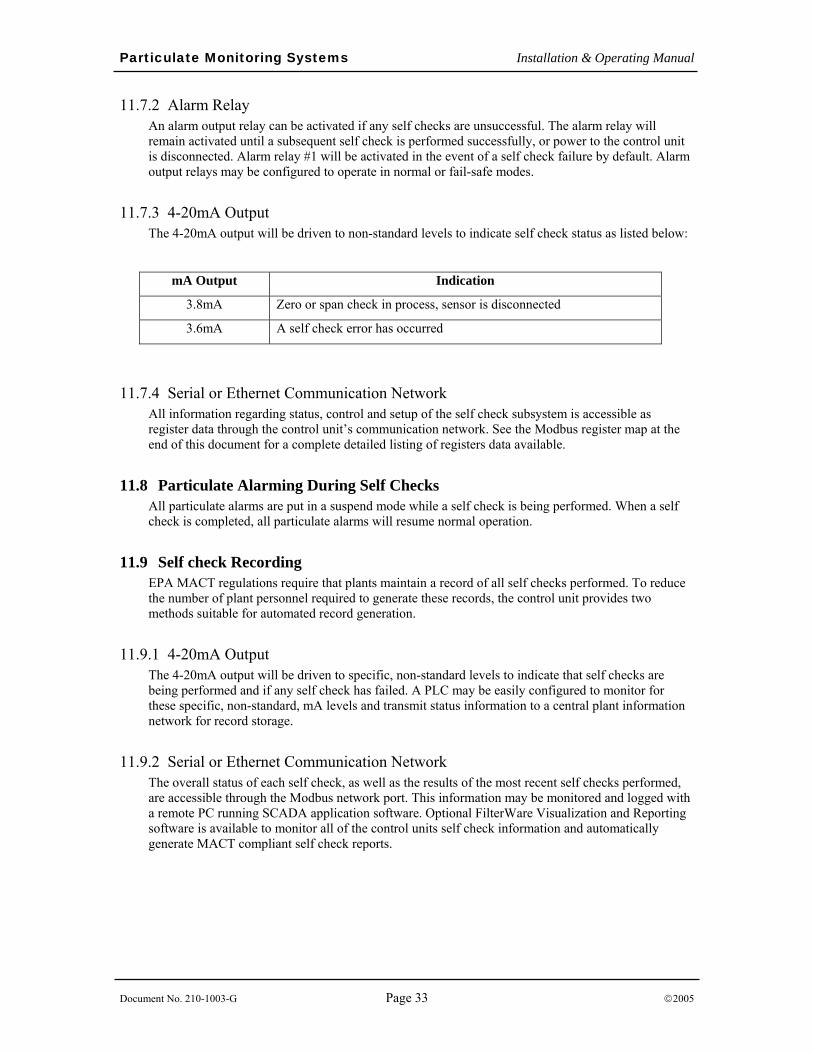
11.7.3 4-20mA Output The 4-20mA output will be driven to non-standard levels to indicate self check status as listed below:
mA Output Indication
3.8mA Zero or span check in process, sensor is disconnected
3.6mA A self check error has occurred
11.7.4 Serial or Ethernet Communication Network All information regarding status, control and setup of the self check subsystem is accessible as register data through the control unit’s communication network. See the Modbus register map at the end of this document for a complete detailed listing of registers data available.
11.8 Particulate Alarming During Self Checks All particulate alarms are put in a suspend mode while a self check is being performed. When a self check is completed, all particulate alarms will resume normal operation.
11.9 Self check Recording EPA MACT regulations require that plants maintain a record of all self checks performed. To reduce the number of plant personnel required to generate these records, the control unit provides two methods suitable for automated record generation.
11.9.1 4-20mA Output The 4-20mA output will be driven to specific, non-standard levels to indicate that self checks are being performed and if any self check has failed. A PLC may be easily configured to monitor for these specific, non-standard, mA levels and transmit status information to a central plant information network for record storage.
11.9.2 Serial or Ethernet Communication Network The overall status of each self check, as well as the results of the most recent self checks performed, are accessible through the Modbus network port. This information may be monitored and logged with a remote PC running SCADA application software. Optional FilterWare Visualization and Reporting software is available to monitor all of the control units self check information and automatically generate MACT compliant self check reports.
Particulate Monitoring Systems Installation & Operating Manual
Document No. 210-1003-G Page 34 ©2005
12. Troubleshooting The following is primarily used when troubleshooting a system without the optional automatic self checks. When troubleshooting, consider each component of the system: The control unit, the sensor coax cable and the sensor assembly.
False High Signals (False Alarms)
1. When an apparent false high signal is present, first check the process to be sure the particulate level has not increased. Keep in mind that the system can detect very low levels. In filtration applications the system can detect invisible particulate levels and very small emissions.
2. Check the sensor cover and conduit seal to be sure they were not left open allowing rain to enter the housing. Check the coaxial cable connectors using a digital voltmeter and check for shorts. If nothing can be found, conduct a manual system zero check.
No Reading or Alarm (When Believed Necessary)
1. Increase the particulate level or introduce particulate into the air stream and monitor for a response. If the system responds properly re-evaluate the selected alarm points and the process conditions.
2. If there is no response, check for electrical continuity from the sensor to the control unit end of the coax cable.
3. Contact the factory for a Field Test Unit that can generate a signal to check response and calibration.
13. Routine Maintenance
EQUIPMENT MAINTENANCE
• Only appropriately licensed professionals should perform maintenance on this product.
• WARNING – To prevent ignition of flammable or combustible atmospheres and for operator safety, always disconnect power before servicing.
Particulate Sensor: There is no electronic calibration or zero adjustment for the sensor. The sensor does not normally need any cleaning and for optimal performance, routine cleaning of the sensor is not recommended.
Control Unit: The viewing window, keypad and enclosure may be cleaned with soap and water as needed. Use a soft cloth to prevent scratching the window. Do not use an abrasive pad or any chemicals that will attack plastic or Lexan.
Particulate Monitoring Systems Installation & Operating Manual
Document No. 210-1003-G Page 35 ©2005
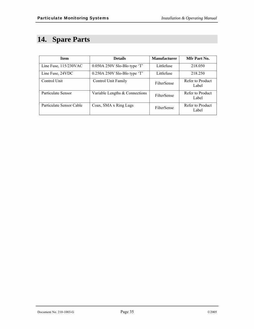
14. Spare Parts
Item Details Manufacturer Mfr Part No.
Line Fuse, 115/230VAC 0.050A 250V Slo-Blo type ‘T’ Littlefuse 218.050
Line Fuse, 24VDC 0.250A 250V Slo-Blo type ‘T’ Littlefuse 218.250
Control Unit Control Unit Family FilterSense Refer to Product Label
Particulate Sensor Variable Lengths & Connections FilterSense Refer to Product Label
Particulate Sensor Cable Coax, SMA x Ring Lugs FilterSense Refer to Product Label
Particulate Monitoring Systems Installation & Operating Manual
Document No. 210-1003-G Page 36 ©2005
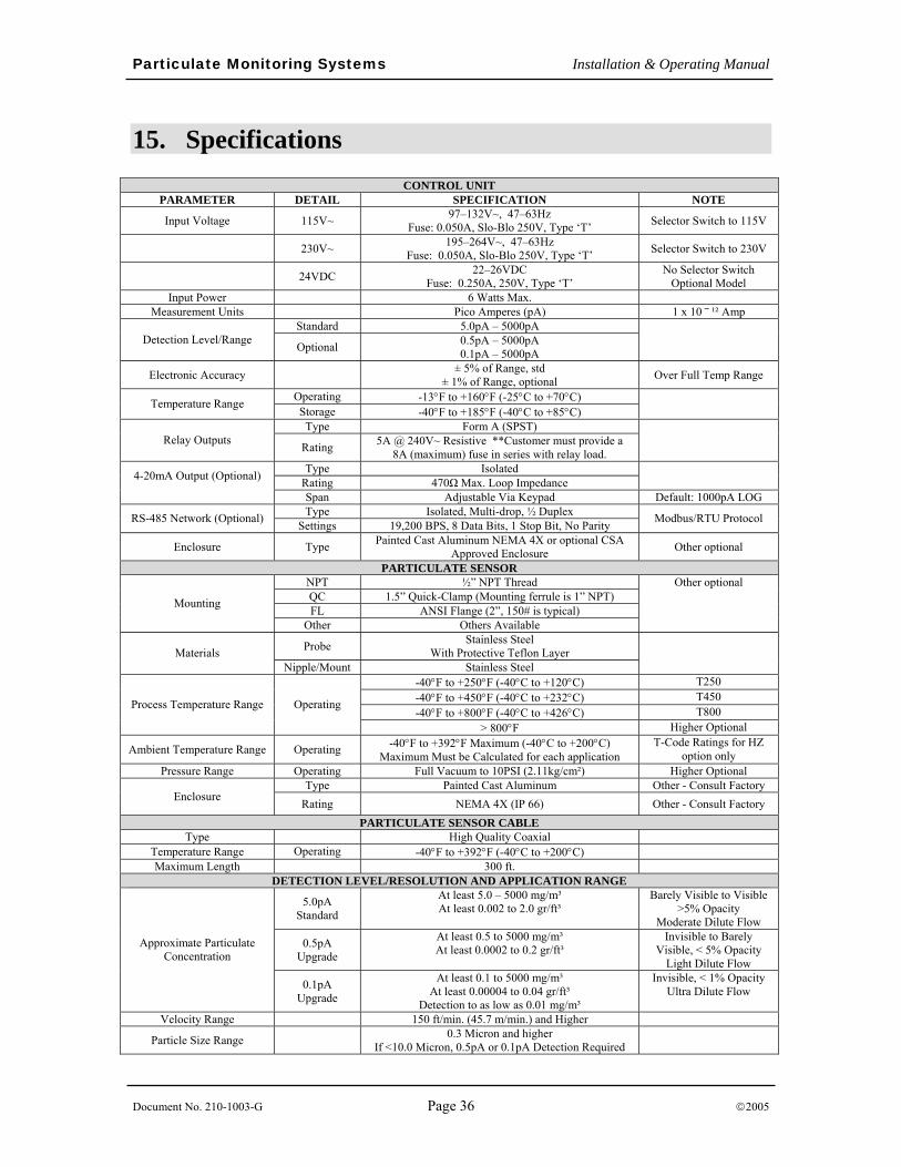
15. Specifications CONTROL UNIT
PARAMETER DETAIL SPECIFICATION NOTE
Input Voltage 115V~ 97–132V~, 47–63Hz Fuse: 0.050A, Slo-Blo 250V, Type ‘T’ Selector Switch to 115V
230V~ 195–264V~, 47–63Hz Fuse: 0.050A, Slo-Blo 250V, Type ‘T’ Selector Switch to 230V
24VDC 22–26VDC Fuse: 0.250A, 250V, Type ‘T’
No Selector Switch Optional Model
Input Power 6 Watts Max. Measurement Units Pico Amperes (pA) 1 x 10 ⎯ ¹² Amp
Standard 5.0pA – 5000pA Detection Level/Range Optional 0.5pA – 5000pA
0.1pA – 5000pA
Electronic Accuracy ± 5% of Range, std ± 1% of Range, optional Over Full Temp Range
Operating -13°F to +160°F (-25°C to +70°C) Temperature Range Storage -40°F to +185°F (-40°C to +85°C)
Type Form A (SPST) Relay Outputs Rating 5A @ 240V~ Resistive **Customer must provide a
8A (maximum) fuse in series with relay load.
Type Isolated Rating 470Ω Max. Loop Impedance 4-20mA Output (Optional)
Span Adjustable Via Keypad Default: 1000pA LOG Type Isolated, Multi-drop, ½ Duplex RS-485 Network (Optional) Settings 19,200 BPS, 8 Data Bits, 1 Stop Bit, No Parity Modbus/RTU Protocol
Enclosure Type Painted Cast Aluminum NEMA 4X or optional CSA Approved Enclosure Other optional
PARTICULATE SENSOR NPT ½” NPT Thread QC 1.5” Quick-Clamp (Mounting ferrule is 1” NPT) FL ANSI Flange (2”, 150# is typical) Mounting
Other Others Available
Other optional
Probe Stainless Steel With Protective Teflon Layer Materials
Nipple/Mount Stainless Steel
-40°F to +250°F (-40°C to +120°C) T250 -40°F to +450°F (-40°C to +232°C) T450 -40°F to +800°F (-40°C to +426°C) T800 Process Temperature Range Operating
> 800°F Higher Optional
Ambient Temperature Range Operating -40°F to +392°F Maximum (-40°C to +200°C) Maximum Must be Calculated for each application
T-Code Ratings for HZ option only
Pressure Range Operating Full Vacuum to 10PSI (2.11kg/cm²) Higher Optional Type Painted Cast Aluminum Other - Consult Factory
Enclosure Rating NEMA 4X (IP 66) Other - Consult Factory PARTICULATE SENSOR CABLE
Type High Quality Coaxial Temperature Range Operating -40°F to +392°F (-40°C to +200°C) Maximum Length 300 ft.
DETECTION LEVEL/RESOLUTION AND APPLICATION RANGE
5.0pA Standard
At least 5.0 – 5000 mg/m³ At least 0.002 to 2.0 gr/ft³
Barely Visible to Visible >5% Opacity
Moderate Dilute Flow
0.5pA Upgrade
At least 0.5 to 5000 mg/m³ At least 0.0002 to 0.2 gr/ft³
Invisible to Barely Visible, < 5% Opacity
Light Dilute Flow
Approximate Particulate Concentration
0.1pA Upgrade
At least 0.1 to 5000 mg/m³ At least 0.00004 to 0.04 gr/ft³
Detection to as low as 0.01 mg/m³
Invisible, < 1% Opacity Ultra Dilute Flow
Velocity Range 150 ft/min. (45.7 m/min.) and Higher
Particle Size Range 0.3 Micron and higher If <10.0 Micron, 0.5pA or 0.1pA Detection Required
Particulate Monitoring Systems Installation & Operating Manual
Document No. 210-1003-G Page 37 ©2005
16. Appendix
Modbus RTU, RS-485 Networking
Non-hazardous Area Installation Drawings
Hazardous Area Control Drawing
Particulate Monitoring Systems Installation & Operating Manual
Document No. 210-1003-G Page 38 ©2005
16.1 Modbus/RTU RS-485 Networking The RS-485 networking feature allows up to 32 control units to be connected to a multi-drop communications network. When connected to the network, any device on the network may be monitored and controlled by a remote device such as a PLC or Computer using Modbus/RTU protocol.
Network Hardware Description RS-485 is a standard industrial network used for serial communications between multiple devices from a single connection. Electrical communication signals are transmitted differentially providing immunity to electrical noise and power supply variances. Signals are transmitted between devices over a single twisted pair wire with shield. Communications are half-duplex (cannot transmit and receive at the same time). Serial baud rate is fixed at 19,200 bps. The serial frame is fixed at 8 data bits, 1 stop bit and no parity. Communications are supported over a maximum network length of 4000 feet. When connecting more than two devices on the network, all devices should be wired ‘in-line’ and not in a ‘star’ configuration.
A terminating resistor must be present at each end of the RS-485 network to eliminate transmission reflections on the serial line. Some control units contain a two-position jumper to allow the device to be either terminated (T) or un-terminated (U). The terminating resistor connected in the (T) position is 120Ohms. All other devices on the network that are not at a network end must be set to un-terminated (U). For control units that do not contain a terminating jumper, a 120ohm ½ watt resistor may be placed across the RS-485 +/- output terminals.
PLC Connection Connection to plant PLC’s is dependant upon the communications ports available on the specific PLC being used. Ensure that the communications port connected to is not limited to a PLC manufacturer’s proprietary network protocol such as Allen-Bradley Data-Highway or Remote I/O. Modicon’s Modbus “Plus” protocol is also not supported. This is a Modbus RTU protocol.
Some configuration may be required in the PLC to set the communications port to Modbus/RTU.
RS-485 Communications Ports A network connection may be directly wired to any communication ports that support half-duplex RS-485 and Modbus/RTU protocols. Refer to the PLC manufacturer’s literature for specific details on connections to the PLC communications port.
Network connections to RS-232/RS-232C or RS-422 ports are supported with the addition of a converter module. As with the RS-485 port, the Modbus/RTU protocol must be supported for proper operation. Converter modules are available from the factory. The converter module modifies the voltage levels and wiring connections to allow different RS connections to work together. Converter modules generally require their own power source, which must be provided in the PLC cabinet.
When using an RS-485 to RS-232 converter the converter must be setup so it will transmit when the TD line is asserted.
Particulate Monitoring Systems Installation & Operating Manual
Document No. 210-1003-G Page 39 ©2005
Personal Computer Connection Connection to a personal computer is made to the RS-232 COM port with the addition of a converter module. Converter modules are available from the factory. The converter module modifies the voltage levels and wiring connections to allow different RS connections to work together. Converter modules generally require their own power source, which may be supplied with a wall-mount transformer power supply.
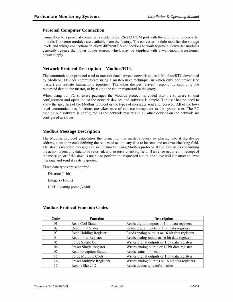
Network Protocol Description – Modbus/RTU The communication protocol used to transmit data between network nodes is Modbus/RTU developed by Modicon. Devices communicate using a master-slave technique, in which only one device (the master) can initiate transactions (queries). The other devices (slaves) respond by supplying the requested data to the master, or by taking the action requested in the query.
When using our PC software packages the Modbus protocol is coded into the software so that configuration and operation of the network devices and software is simple. The user has no need to know the specifics of the Modbus protocol or the types of messages sent and received. All of the low-level communications functions are taken care of and are transparent to the system user. The PC running our software is configured as the network master and all other devices on the network are configured as slaves.
Modbus Message Description The Modbus protocol establishes the format for the master’s query by placing into it the device address, a function code defining the requested action, any data to be sent, and an error-checking field. The slave’s response message is also constructed using Modbus protocol. It contains fields confirming the action taken, any data to be returned, and an error-checking field. If an error occurred in receipt of the message, or if the slave is unable to perform the requested action, the slave will construct an error message and send it as its response.
Three data types are supported:
Discrete (1-bit)
Integers (16-bit)
IEEE Floating point (32-bit)
Modbus Protocol Function Codes
Code Function Description 01 Read Coil Status Reads digital outputs or 1 bit data registers 02 Read Input Status Reads digital inputs or 1 bit data registers 03 Read Holding Register Reads analog outputs or 16 bit data registers 04 Read Input Register Reads analog inputs or 16 bit data registers 05 Force Single Coil Writes digital outputs or 1 bit data registers 06 Preset Single Register Writes analog output or 16 bit data register 07 Read Exception Status Reads status information 15 Force Multiple Coils Writes digital outputs or 1 bit data registers 16 Preset Multiple Registers Writes analog outputs or 16 bit data registers 17 Report Slave ID Reads device type information
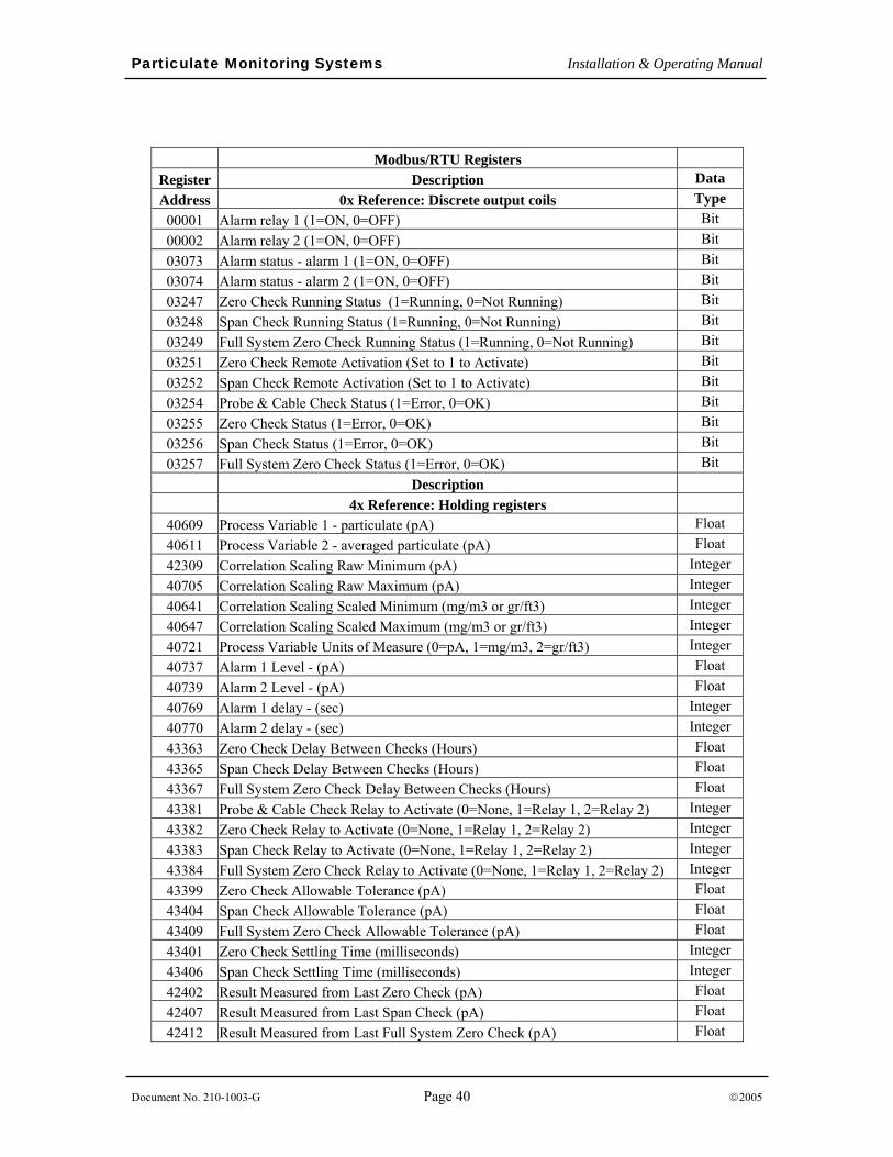
Particulate Monitoring Systems Installation & Operating Manual
Document No. 210-1003-G Page 40 ©2005
Modbus/RTU Registers
Register Description Data Address 0x Reference: Discrete output coils Type 00001 Alarm relay 1 (1=ON, 0=OFF) Bit 00002 Alarm relay 2 (1=ON, 0=OFF) Bit 03073 Alarm status - alarm 1 (1=ON, 0=OFF) Bit 03074 Alarm status - alarm 2 (1=ON, 0=OFF) Bit 03247 Zero Check Running Status (1=Running, 0=Not Running) Bit 03248 Span Check Running Status (1=Running, 0=Not Running) Bit 03249 Full System Zero Check Running Status (1=Running, 0=Not Running) Bit 03251 Zero Check Remote Activation (Set to 1 to Activate) Bit 03252 Span Check Remote Activation (Set to 1 to Activate) Bit 03254 Probe & Cable Check Status (1=Error, 0=OK) Bit 03255 Zero Check Status (1=Error, 0=OK) Bit 03256 Span Check Status (1=Error, 0=OK) Bit 03257 Full System Zero Check Status (1=Error, 0=OK) Bit
Description 4x Reference: Holding registers
40609 Process Variable 1 - particulate (pA) Float 40611 Process Variable 2 - averaged particulate (pA) Float 42309 Correlation Scaling Raw Minimum (pA) Integer 40705 Correlation Scaling Raw Maximum (pA) Integer 40641 Correlation Scaling Scaled Minimum (mg/m3 or gr/ft3) Integer 40647 Correlation Scaling Scaled Maximum (mg/m3 or gr/ft3) Integer 40721 Process Variable Units of Measure (0=pA, 1=mg/m3, 2=gr/ft3) Integer 40737 Alarm 1 Level - (pA) Float 40739 Alarm 2 Level - (pA) Float 40769 Alarm 1 delay - (sec) Integer 40770 Alarm 2 delay - (sec) Integer 43363 Zero Check Delay Between Checks (Hours) Float 43365 Span Check Delay Between Checks (Hours) Float 43367 Full System Zero Check Delay Between Checks (Hours) Float 43381 Probe & Cable Check Relay to Activate (0=None, 1=Relay 1, 2=Relay 2) Integer 43382 Zero Check Relay to Activate (0=None, 1=Relay 1, 2=Relay 2) Integer 43383 Span Check Relay to Activate (0=None, 1=Relay 1, 2=Relay 2) Integer 43384 Full System Zero Check Relay to Activate (0=None, 1=Relay 1, 2=Relay 2) Integer 43399 Zero Check Allowable Tolerance (pA) Float 43404 Span Check Allowable Tolerance (pA) Float 43409 Full System Zero Check Allowable Tolerance (pA) Float 43401 Zero Check Settling Time (milliseconds) Integer 43406 Span Check Settling Time (milliseconds) Integer 42402 Result Measured from Last Zero Check (pA) Float 42407 Result Measured from Last Span Check (pA) Float 42412 Result Measured from Last Full System Zero Check (pA) Float
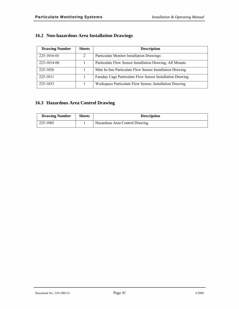
Particulate Monitoring Systems Installation & Operating Manual
Document No. 210-1003-G Page 41 ©2005
16.2 Non-hazardous Area Installation Drawings
Drawing Number Sheets Description
225-1016-01 2 Particulate Monitor Installation Drawings
225-1014-06 1 Particulate Flow Sensor Installation Drawing, All Mounts
225-1026 1 Mini In-line Particulate Flow Sensor Installation Drawing
225-1011 1 Faraday Cage Particulate Flow Sensor Installation Drawing
225-1033 1 Workspace Particulate Flow Sensor, Installation Drawing
16.3 Hazardous Area Control Drawing
Drawing Number Sheets Description
225-1005 1 Hazardous Area Control Drawing