parts catalog - robust, rigid and reliable hdpe · pdf filedirections for the parts catalog....
TRANSCRIPT
PARTS CATALOG
0CR10-G67600
2010/4 (Apr.)Published
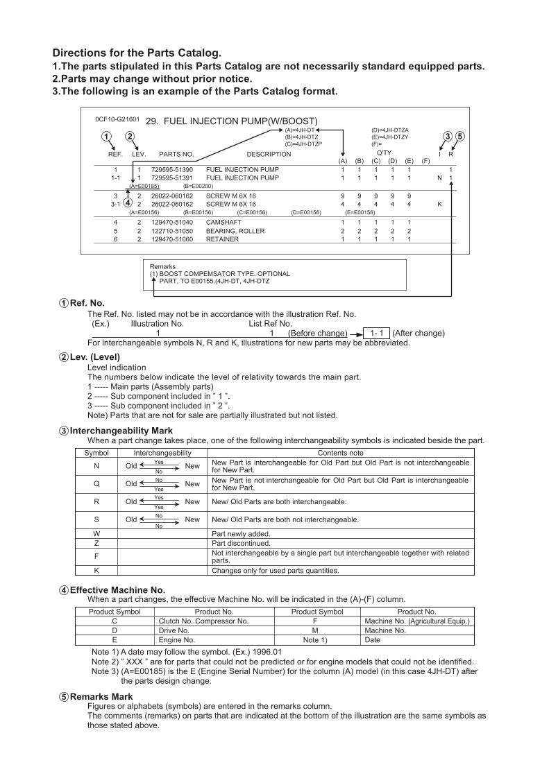
Directions for the Parts Catalog. 1.The parts stipulated in this Parts Catalog are not necessarily standard equipped parts. 2.Parts may change without prior notice. 3.The following is an example of the Parts Catalog format.
Ref. No.The Ref. No. listed may not be in accordance with the illustration Ref. No. (Ex.) Illustration No. List Ref No. 1 1 (Before change)
For interchangeable symbols N, R and K, illustrations for new parts may be abbreviated.
Lev. (Level) Level indication The numbers below indicate the level of relativity towards the main part.1 ----- Main parts (Assembly parts) 2 ----- Sub component included in ” 1 ”. 3 ----- Sub component included in ” 2 “. Note) Parts that are not for sale are partially illustrated but not listed.
Interchangeability Mark When a part change takes place, one of the following interchangeability symbols is indicated beside the part.
Effective Machine No. When a part changes, the effective Machine No. will be indicated in the (A)-(F) column.
Note 1) A date may follow the symbol. (Ex.) 1996.01 Note 2) ” XXX ” are for parts that could not be predicted or for engine models that could not be identified. Note 3) (A=E00185) is the E (Engine Serial Number) for the column (A) model (in this case 4JH-DT) after
the parts design change.
Remarks Mark Figures or alphabets (symbols) are entered in the remarks column. The comments (remarks) on parts that are indicated at the bottom of the illustration are the same symbols as those stated above.
1- 1 (After change)
Product Symbol Product No. Product Symbol Product No. C Clutch No. Compressor No.
Machine No.Machine No. (Agricultural Equip.)
MF
.oNevirDDE Engine No. Note 1) Date
R
S
WZ
K
N
Q
F
NewOld Yes
NoNo
YesYes
Yes
NewOld
No
No
NewOld
NewOld
Contents noteInterchangeabilitySymbol
New/ Old Parts are both interchangeable.
New/ Old Parts are both not interchangeable.
Part discontinued. Part newly added.
Changes only for used parts quantities.
New Part is interchangeable for Old Part but Old Part is not interchangeablefor New Part.New Part is not interchangeable for Old Part but Old Part is interchangeablefor New Part.
Not interchangeable by a single part but interchangeable together with relatedparts.
1
2
4
3
5
0CF10-G21601 29. FUEL INJECTION PUMP(W/BOOST)
(F)=(E)=4JH-DTZY(D)=4JH-DTZA
(C)=4JH-DTZP(B)=4JH-DTZ(A)=4JH-DT
LEV.REF. PARTS NO. DESCRIPTION RIQ'TY(F)(D)(C)(B)(A) (E)
1FUEL INJECTION PUMP729595-5139011 111111FUEL INJECTION PUMP729595-5139111-1 N11111
(A=E00185) (B=E00200)
SCREW M 6X 1626022-06016223 99999SCREW M 6X 1626022-06016223-1 K44444
(A=E00156) (B=E00156) (C=E00156) (D=E00156) (E=E00156)
CAMSHAFT129470-5104024 11111BEARING, ROLLER122710-5105025 22222RETAINER129470-5106026 11111
Remarks(1) BOOST COMPEMSATOR TYPE. OPTIONAL
PART, TO E00155,(4JH-DT, 4JH-DTZ
3 51 2
4
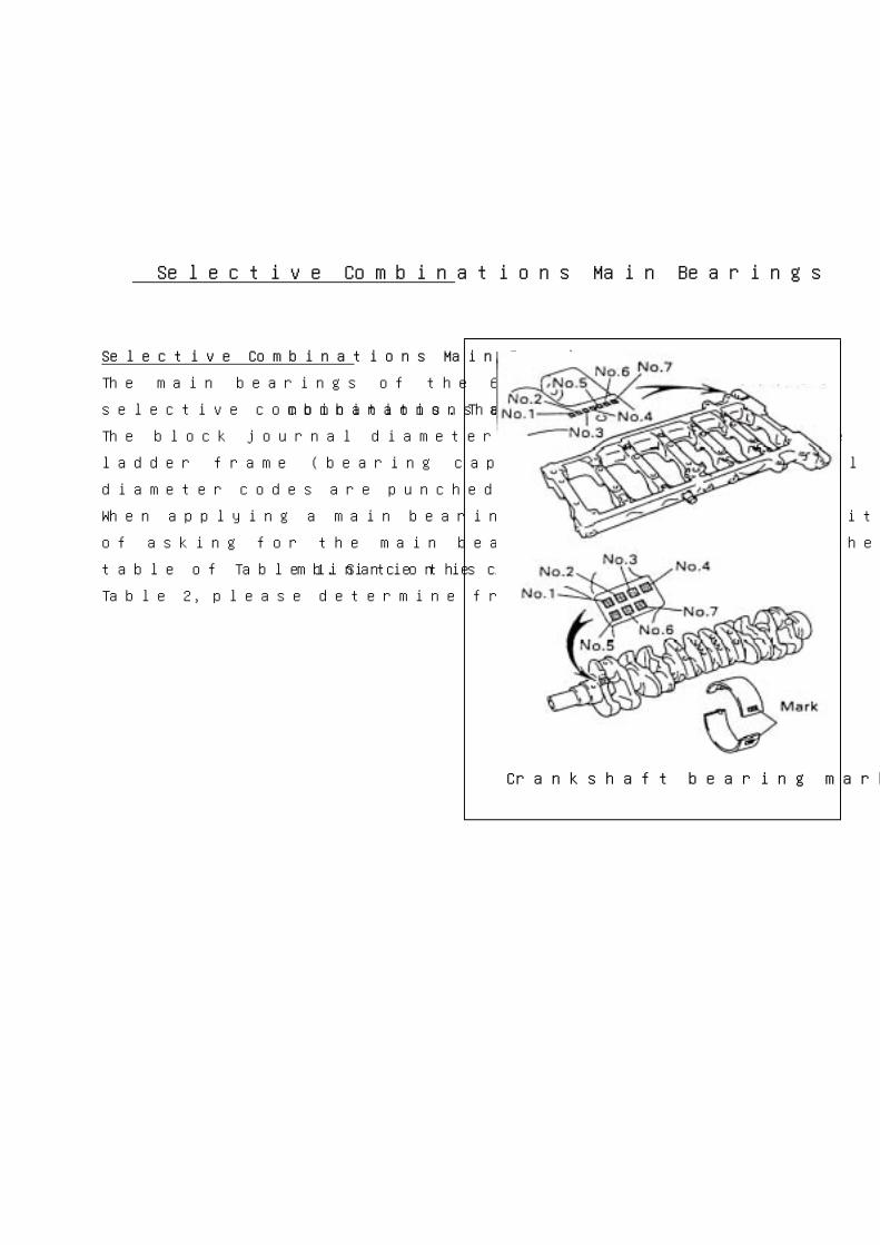
Selective Combinations Main Bearings
Selective Combinations Main Bearings
The main bearings of the 6LP series employ the
selective combinations. The combinations as follows.
The block journal diameter codes are shown on the
ladder frame (bearing cap) and the crank journal
diameter codes are punched on the crank.
When applying a main bearings, there is the necessity
of asking for the main bearings which suits on the
table of Table 1. Since the combination is indicated to
Table 2, please determine from this.
Crankshaft bearing mark position
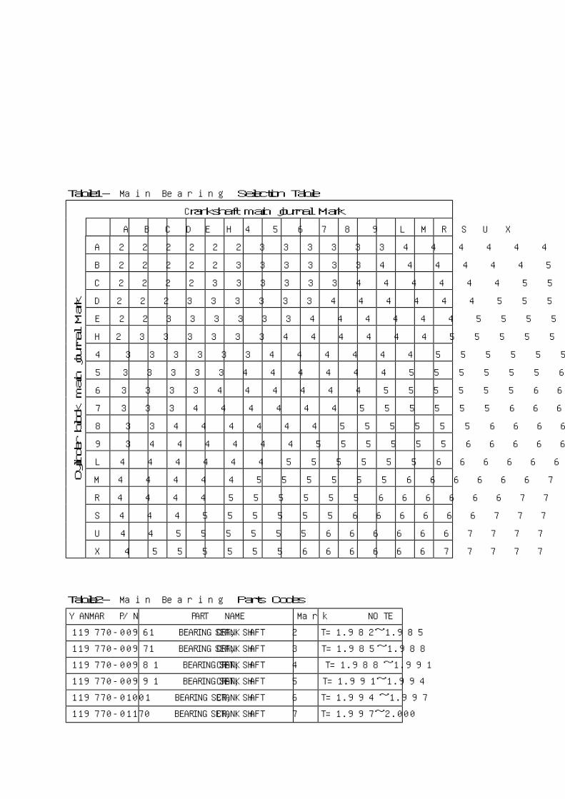
Table1- Main Bearing Selection Table
Crankshaft main journal Mark
A B C D E H 4 5 6 7 8 9 L M R S U X
A 2 2 2 2 2 2 3 3 3 3 3 3 4 4 4 4 4 4
B 2 2 2 2 2 3 3 3 3 3 3 4 4 4 4 4 4 5
C 2 2 2 2 3 3 3 3 3 3 4 4 4 4 4 4 5 5
D 2 2 2 3 3 3 3 3 3 4 4 4 4 4 4 5 5 5
E 2 2 3 3 3 3 3 3 4 4 4 4 4 4 5 5 5 5
H 2 3 3 3 3 3 3 4 4 4 4 4 4 5 5 5 5 5
4 3 3 3 3 3 3 4 4 4 4 4 4 5 5 5 5 5 5
5 3 3 3 3 3 4 4 4 4 4 4 5 5 5 5 5 5 6
6 3 3 3 3 4 4 4 4 4 4 5 5 5 5 5 5 6 6
7 3 3 3 4 4 4 4 4 4 5 5 5 5 5 5 6 6 6
8 3 3 4 4 4 4 4 4 5 5 5 5 5 5 6 6 6 6
9 3 4 4 4 4 4 4 5 5 5 5 5 5 6 6 6 6 6
L 4 4 4 4 4 4 5 5 5 5 5 5 6 6 6 6 6 6
M 4 4 4 4 4 5 5 5 5 5 5 6 6 6 6 6 6 7
R 4 4 4 4 5 5 5 5 5 5 6 6 6 6 6 6 7 7
S 4 4 4 5 5 5 5 5 5 6 6 6 6 6 6 7 7 7
U 4 4 5 5 5 5 5 5 6 6 6 6 6 6 7 7 7 7
Cyl
inder
blo
ck m
ain
journ
al
Mark
X 4 5 5 5 5 5 5 6 6 6 6 6 6 7 7 7 7 7
Table2- Main Bearing Parts Codes
YANMAR P/N PART NAME Mark NOTE
119770-00961 BEARING SET,CRANKSHAFT 2 T=1.982~1.985
119770-00971 BEARING SET,CRANKSHAFT 3 T=1.985~1.988
119770-00981 BEARING SET,CRANKSHAFT 4 T=1.988~1.991
119770-00991 BEARING SET,CRANKSHAFT 5 T=1.991~1.994
119770-01001 BEARING SET,CRANKSHAFT 6 T=1.994~1.997
119770-01170 BEARING SET,CRANKSHAFT 7 T=1.997~2.000
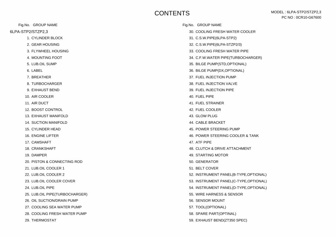
PC NO : 0CR10-G67600 CONTENTS MODEL : 6LPA-STP2/STZP2,3
Fig.No. GROUP NAME Fig.No. GROUP NAME
6LPA-STP2/STZP2,3 CYLINDER BLOCK 1.
GEAR HOUSING 2.
FLYWHEEL HOUSING 3.
MOUNTING FOOT 4.
LUB.OIL SUMP 5.
LABEL 6.
BREATHER 7.
TURBOCHARGER 8.
EXHAUST BEND 9.
AIR COOLER 10.
AIR DUCT 11.
BOOST CONTROL 12.
EXHAUST MANIFOLD 13.
SUCTION MANIFOLD 14.
CYLINDER HEAD 15.
ENGINE LIFTER 16.
CAMSHAFT 17.
CRANKSHAFT 18.
DAMPER 19.
PISTON & CONNECTING ROD 20.
LUB.OIL COOLER 1 21.
LUB.OIL COOLER 2 22.
LUB.OIL COOLER COVER 23.
LUB.OIL PIPE 24.
LUB.OIL PIPE(TURBOCHARGER) 25.
OIL SUCTION/DRAIN PUMP 26.
COOLING SEA WATER PUMP 27.
COOLING FRESH WATER PUMP 28.
THERMOSTAT 29.
COOLING FRESH WATER COOLER 30.
C.S.W.PIPE(6LPA-STP2) 31.
C.S.W.PIPE(6LPA-STZP2/3) 32.
COOLING FRESH WATER PIPE 33.
C.F.W.WATER PIPE(TURBOCHARGER) 34.
BILGE PUMP(STD,OPTIONAL) 35.
BILGE PUMP(DX,OPTIONAL) 36.
FUEL INJECTION PUMP 37.
FUEL INJECTION VALVE 38.
FUEL INJECTION PIPE 39.
FUEL PIPE 40.
FUEL STRAINER 41.
FUEL COOLER 42.
GLOW PLUG 43.
CABLE BRACKET 44.
POWER STEERING PUMP 45.
POWER STEERING COOLER & TANK 46.
ATF PIPE 47.
CLUTCH & DRIVE ATTACHMENT 48.
STARTING MOTOR 49.
GENERATOR 50.
BELT COVER 51.
INSTRUMENT PANEL(B-TYPE,OPTIONAL) 52.
INSTRUMENT PANEL(C-TYPE,OPTIONAL) 53.
INSTRUMENT PANEL(D-TYPE,OPTIONAL) 54.
WIRE HARNESS & SENSOR 55.
SENSOR MOUNT 56.
TOOL(OPTIONAL) 57.
SPARE PART(OPTINAL) 58.
EXHAUST BEND(ZT350 SPEC) 59.
PC NO : 0CR10-G67600 CONTENTS MODEL : 6LPA-STP2/STZP2,3
Fig.No. GROUP NAME Fig.No. GROUP NAME
C.S.W.PIPE(ZT350 SPEC) 60.
COUPLING(ZT350 SPEC) 61.
EXHAUST MIXING DEVICE & FLEXIBLE RUBBER(KMH50V SPEC.) 62.
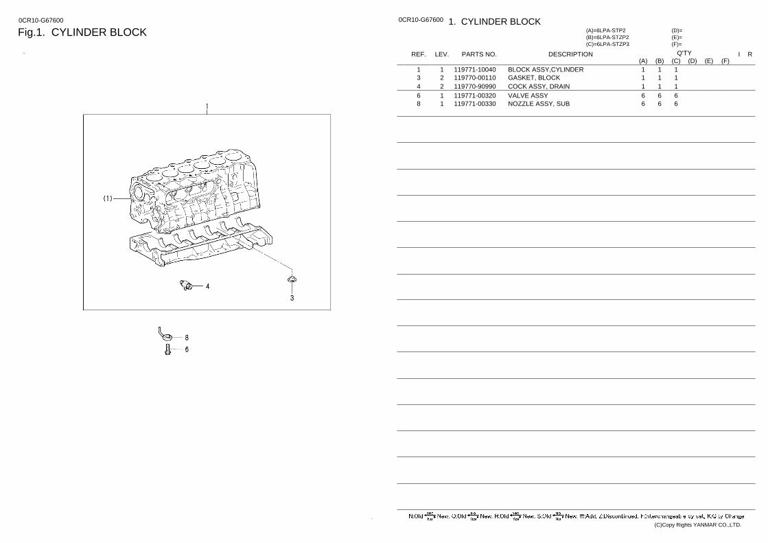
Fig.1. CYLINDER BLOCK 0CR10-G67600 0CR10-G67600 1. CYLINDER BLOCK
(F)= (E)= (D)=
(C)=6LPA-STZP3 (B)=6LPA-STZP2 (A)=6LPA-STP2
LEV. REF. PARTS NO. DESCRIPTION R I Q'TY (F) (D) (C) (B) (A) (E)
BLOCK ASSY,CYLINDER 119771-10040 1 1 1 1 1 GASKET, BLOCK 119770-00110 2 3 1 1 1 COCK ASSY, DRAIN 119770-90990 2 4 1 1 1 VALVE ASSY 119771-00320 1 6 6 6 6 NOZZLE ASSY, SUB 119771-00330 1 8 6 6 6
(C)Copy Rights YANMAR CO.,LTD.

Fig.2. GEAR HOUSING 0CR10-G67600 0CR10-G67600 2. GEAR HOUSING
(F)= (E)= (D)=
(C)=6LPA-STZP3 (B)=6LPA-STZP2 (A)=6LPA-STP2
LEV. REF. PARTS NO. DESCRIPTION R I Q'TY (F) (D) (C) (B) (A) (E)
CASE ASSY, TIMING 119771-00060 2 2 1 1 1 GASKET, OIL PUMP 119770-00160 2 3 1 1 1 PLUG 119771-90110 2 4 1 1 1 BOLT 119771-90120 2 5 7 7 7 PARALLEL PIN 119770-90250 2 6 1 1 1 STUD, D10XL40 119770-01210 2 7 2 2 2 BOLT,STUD 119770-01220 2 8 2 2 2 BOLT 119771-90140 2 10 6 6 6 STUD, D10XL45.6 119770-90270 2 11 2 2 2 SEAL, OIL 119770-90280 2 12 1 1 1 SEAL, OIL 119770-90290 2 13 1 1 1 COVER, TIMING GEAR 119771-00071 2 14 1 1 1 BOLT 119771-90130 2 15 9 9 9 COVER, TIMING VELT 119771-00081 2 17 1 1 1 BOLT 119770-90320 2 18 6 6 6 WASHER 119770-90330 2 19 6 6 6 GASKET,COVER 119773-01590 1 20 1 1 1 RETAINER, CAMSHAFT 119771-00101 2 22 1 1 1 PIN, LINK 119770-90020 2 23 2 2 2 BOLT 119771-90120 2 24 4 4 4 SEAL, OIL 119771-90160 2 25 1 1 1 PLATE 119770-00201 2 27 1 1 1 BOLT 119770-90350 2 28 1 1 1 RETAINER, OIL SEAL 119770-00030 2 30 1 1 1 SEAL, OIL 119770-90090 2 31 1 1 1 BOLT, FLANGE 119770-90100 2 32 6 6 6 VALVE, RELIEF 119770-01240 2 34 1 1 1 SPRING, RELIEF 119770-01250 2 35 1 1 1 PLUG,LO-P RELIEF.V 119770-01260 2 36 1 1 1 GASKET 119771-01270 2 37 1 1 1 WASHER 10 22117-100000 1 38 2 2 2 COVER, GEAR CASE 119773-01580 1 39 1 1 1 SPRING WASHER 10 22217-100000 1 40 2 2 2 U-NUT M10 26376-100002 1 41 1 1 1
(C)Copy Rights YANMAR CO.,LTD.
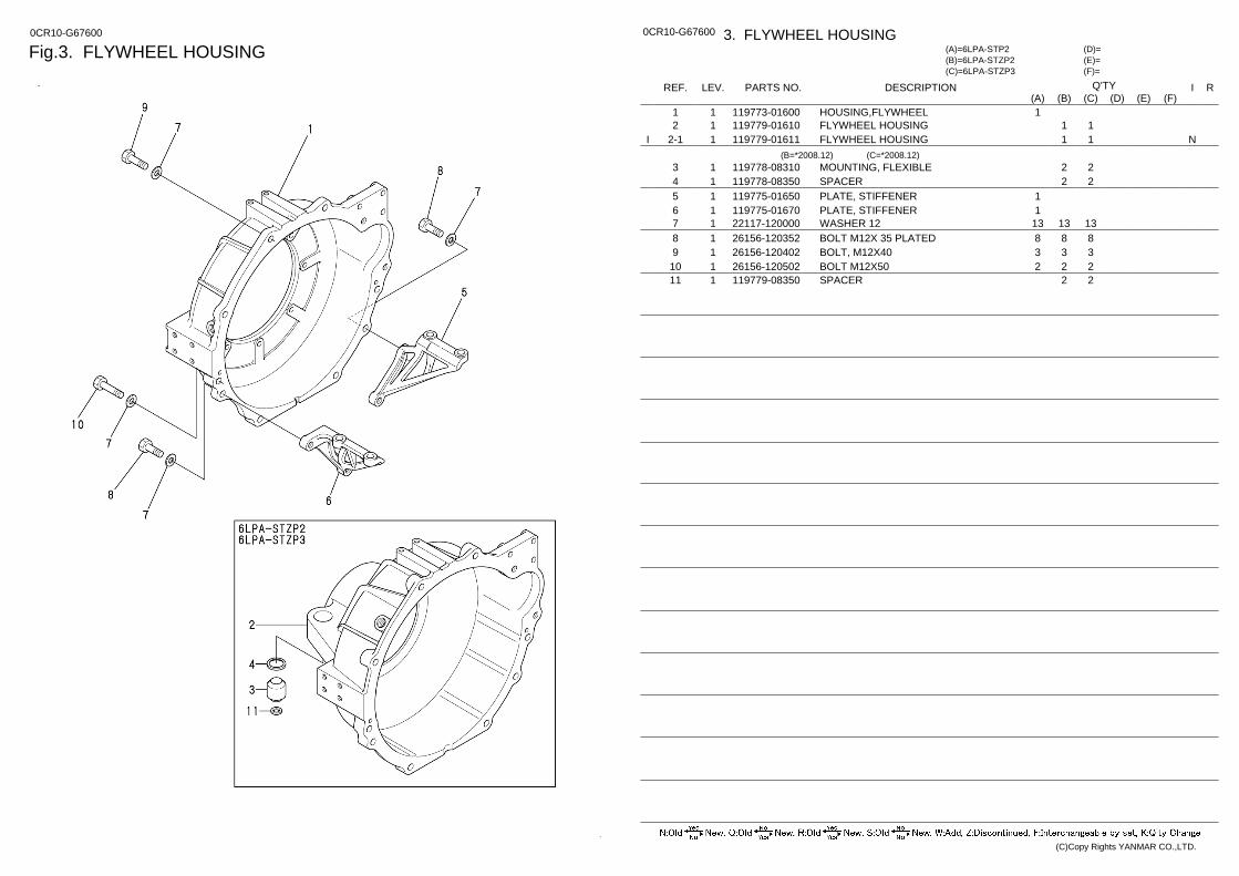
Fig.3. FLYWHEEL HOUSING 0CR10-G67600 0CR10-G67600 3. FLYWHEEL HOUSING
(F)= (E)= (D)=
(C)=6LPA-STZP3 (B)=6LPA-STZP2 (A)=6LPA-STP2
LEV. REF. PARTS NO. DESCRIPTION R I Q'TY (F) (D) (C) (B) (A) (E)
HOUSING,FLYWHEEL 119773-01600 1 1 1 FLYWHEEL HOUSING 119779-01610 1 2 1 1 FLYWHEEL HOUSING 119779-01611 1 2-1 N 1 1 I
(B=*2008.12) (C=*2008.12) MOUNTING, FLEXIBLE 119778-08310 1 3 2 2 SPACER 119778-08350 1 4 2 2 PLATE, STIFFENER 119775-01650 1 5 1 PLATE, STIFFENER 119775-01670 1 6 1 WASHER 12 22117-120000 1 7 13 13 13 BOLT M12X 35 PLATED 26156-120352 1 8 8 8 8 BOLT, M12X40 26156-120402 1 9 3 3 3 BOLT M12X50 26156-120502 1 10 2 2 2 SPACER 119779-08350 1 11 2 2
(C)Copy Rights YANMAR CO.,LTD.
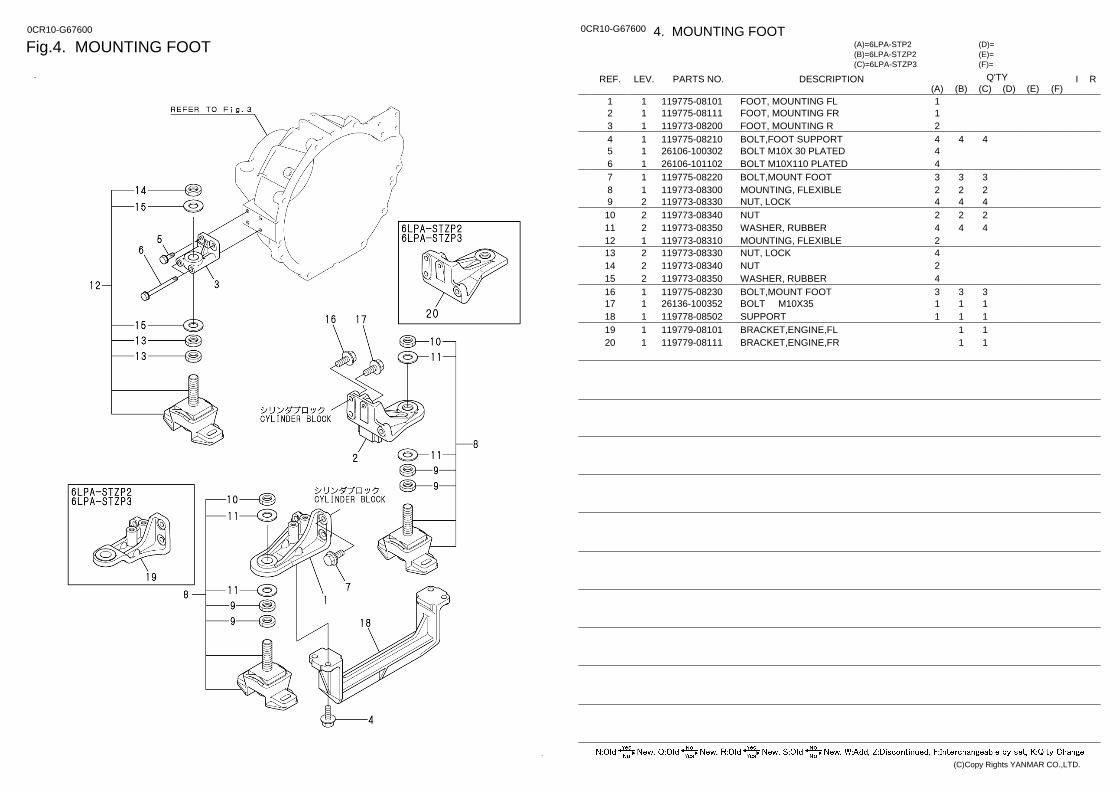
Fig.4. MOUNTING FOOT 0CR10-G67600 0CR10-G67600 4. MOUNTING FOOT
(F)= (E)= (D)=
(C)=6LPA-STZP3 (B)=6LPA-STZP2 (A)=6LPA-STP2
LEV. REF. PARTS NO. DESCRIPTION R I Q'TY (F) (D) (C) (B) (A) (E)
FOOT, MOUNTING FL 119775-08101 1 1 1 FOOT, MOUNTING FR 119775-08111 1 2 1 FOOT, MOUNTING R 119773-08200 1 3 2 BOLT,FOOT SUPPORT 119775-08210 1 4 4 4 4 BOLT M10X 30 PLATED 26106-100302 1 5 4 BOLT M10X110 PLATED 26106-101102 1 6 4 BOLT,MOUNT FOOT 119775-08220 1 7 3 3 3 MOUNTING, FLEXIBLE 119773-08300 1 8 2 2 2 NUT, LOCK 119773-08330 2 9 4 4 4 NUT 119773-08340 2 10 2 2 2 WASHER, RUBBER 119773-08350 2 11 4 4 4 MOUNTING, FLEXIBLE 119773-08310 1 12 2 NUT, LOCK 119773-08330 2 13 4 NUT 119773-08340 2 14 2 WASHER, RUBBER 119773-08350 2 15 4 BOLT,MOUNT FOOT 119775-08230 1 16 3 3 3 BOLT M10X35 26136-100352 1 17 1 1 1 SUPPORT 119778-08502 1 18 1 1 1 BRACKET,ENGINE,FL 119779-08101 1 19 1 1 BRACKET,ENGINE,FR 119779-08111 1 20 1 1
(C)Copy Rights YANMAR CO.,LTD.
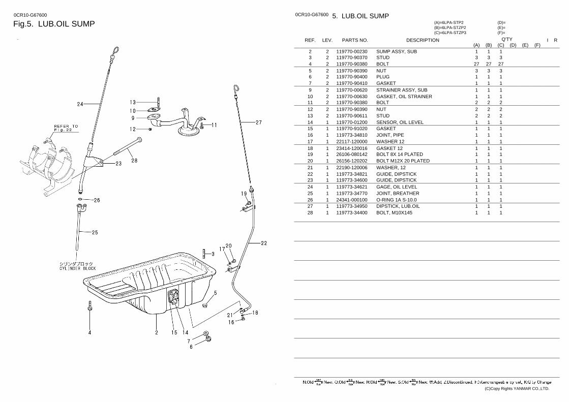
Fig.5. LUB.OIL SUMP 0CR10-G67600 0CR10-G67600 5. LUB.OIL SUMP
(F)= (E)= (D)=
(C)=6LPA-STZP3 (B)=6LPA-STZP2 (A)=6LPA-STP2
LEV. REF. PARTS NO. DESCRIPTION R I Q'TY (F) (D) (C) (B) (A) (E)
SUMP ASSY, SUB 119770-00230 2 2 1 1 1 STUD 119770-90370 2 3 3 3 3 BOLT 119770-90380 2 4 27 27 27 NUT 119770-90390 2 5 3 3 3 PLUG 119770-90400 2 6 1 1 1 GASKET 119770-90410 2 7 1 1 1 STRAINER ASSY, SUB 119770-00620 2 9 1 1 1 GASKET, OIL STRAINER 119770-00630 2 10 1 1 1 BOLT 119770-90380 2 11 2 2 2 NUT 119770-90390 2 12 2 2 2 STUD 119770-90611 2 13 2 2 2 SENSOR, OIL LEVEL 119770-01200 1 14 1 1 1 GASKET 119770-91020 1 15 1 1 1 JOINT, PIPE 119773-34810 1 16 1 1 1 WASHER 12 22117-120000 1 17 1 1 1 GASKET 12 23414-120016 1 18 1 1 1 BOLT 8X 14 PLATED 26106-080142 1 19 1 1 1 BOLT M12X 20 PLATED 26156-120202 1 20 1 1 1 WASHER, 12 22190-120006 1 21 1 1 1 GUIDE, DIPSTICK 119773-34821 1 22 1 1 1 GUIDE, DIPSTICK 119773-34600 1 23 1 1 1 GAGE, OIL LEVEL 119773-34621 1 24 1 1 1 JOINT, BREATHER 119773-34770 1 25 1 1 1 O-RING 1A S-10.0 24341-000100 1 26 1 1 1 DIPSTICK, LUB.OIL 119773-34950 1 27 1 1 1 BOLT, M10X145 119773-34400 1 28 1 1 1
(C)Copy Rights YANMAR CO.,LTD.
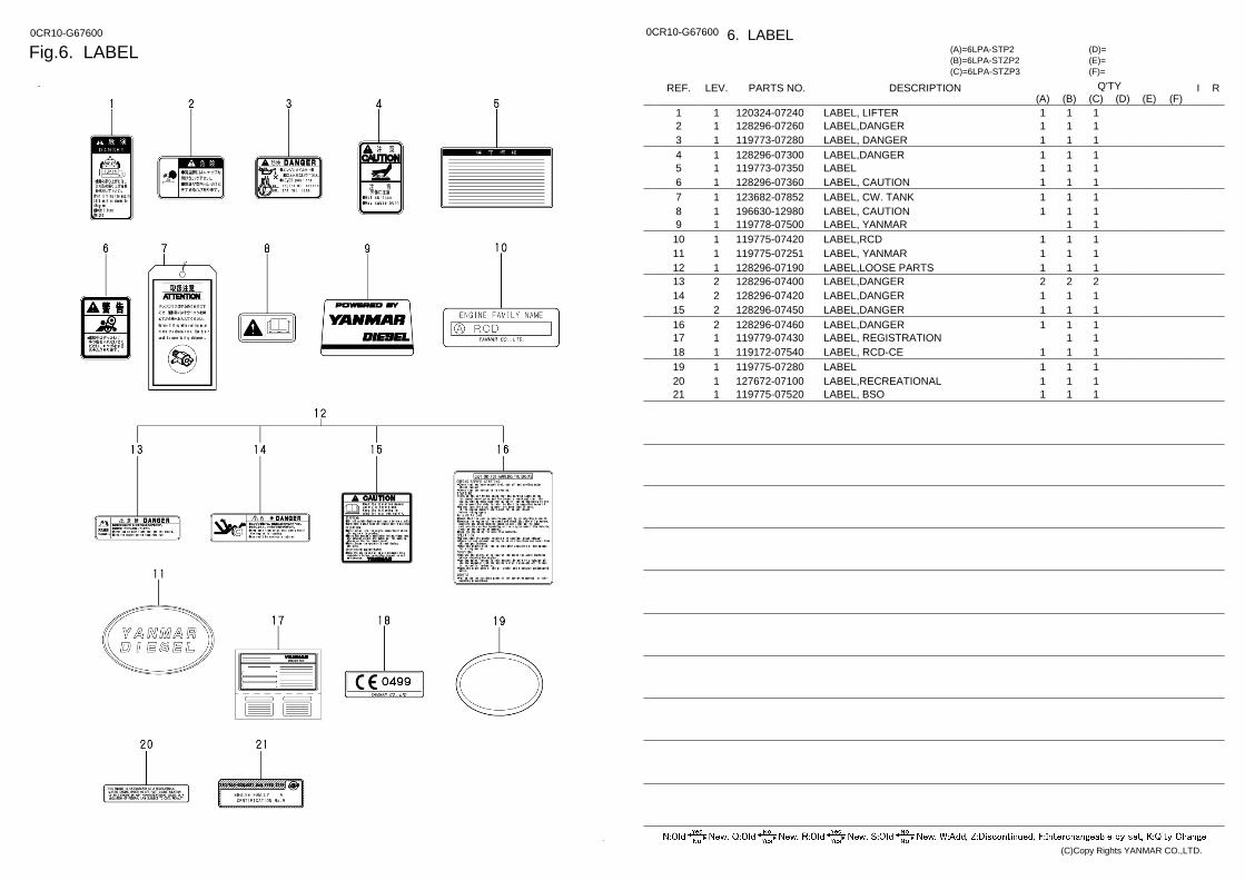
Fig.6. LABEL 0CR10-G67600 0CR10-G67600 6. LABEL
(F)= (E)= (D)=
(C)=6LPA-STZP3 (B)=6LPA-STZP2 (A)=6LPA-STP2
LEV. REF. PARTS NO. DESCRIPTION R I Q'TY (F) (D) (C) (B) (A) (E)
LABEL, LIFTER 120324-07240 1 1 1 1 1 LABEL,DANGER 128296-07260 1 2 1 1 1 LABEL, DANGER 119773-07280 1 3 1 1 1 LABEL,DANGER 128296-07300 1 4 1 1 1 LABEL 119773-07350 1 5 1 1 1 LABEL, CAUTION 128296-07360 1 6 1 1 1 LABEL, CW. TANK 123682-07852 1 7 1 1 1 LABEL, CAUTION 196630-12980 1 8 1 1 1 LABEL, YANMAR 119778-07500 1 9 1 1 LABEL,RCD 119775-07420 1 10 1 1 1 LABEL, YANMAR 119775-07251 1 11 1 1 1 LABEL,LOOSE PARTS 128296-07190 1 12 1 1 1 LABEL,DANGER 128296-07400 2 13 2 2 2 LABEL,DANGER 128296-07420 2 14 1 1 1 LABEL,DANGER 128296-07450 2 15 1 1 1 LABEL,DANGER 128296-07460 2 16 1 1 1 LABEL, REGISTRATION 119779-07430 1 17 1 1 LABEL, RCD-CE 119172-07540 1 18 1 1 1 LABEL 119775-07280 1 19 1 1 1 LABEL,RECREATIONAL 127672-07100 1 20 1 1 1 LABEL, BSO 119775-07520 1 21 1 1 1
(C)Copy Rights YANMAR CO.,LTD.
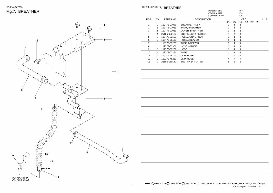
Fig.7. BREATHER 0CR10-G67600 0CR10-G67600 7. BREATHER
(F)= (E)= (D)=
(C)=6LPA-STZP3 (B)=6LPA-STZP2 (A)=6LPA-STP2
LEV. REF. PARTS NO. DESCRIPTION R I Q'TY (F) (D) (C) (B) (A) (E)
BREATHER ASSY 119773-03011 1 1 1 1 1 BODY, BREATHER 119773-03021 2 2 1 1 1 COVER, BREATHER 119773-03031 2 3 1 1 1 BOLT M 6X 12 PLATED 26106-060122 2 4 4 4 4 HOSE,BONNET OUT 119775-03150 1 5 1 1 1 HOSE,BREAZER 119773-03190 1 6 1 1 1 TUBE, BREAZER 119773-03200 1 7 1 1 1 HOSE W/TUBE 119773-03301 1 8 1 1 1 HOSE 119773-03251 2 9 1 1 1 TUBE 119773-03271 2 10 1 1 1 CLIP, HOSE 119172-48190 1 11 2 2 2 CLIP, HOSE 119172-48250 1 12 4 4 4 BOLT 8X 14 PLATED 26106-080142 1 13 5 5 5
(C)Copy Rights YANMAR CO.,LTD.
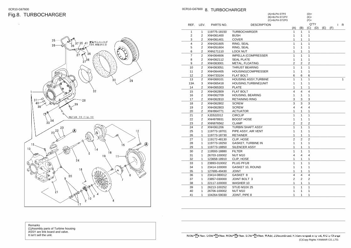
Fig.8. TURBOCHARGER 0CR10-G67600
Remarks (1)Assmbly parts of Turbine housing ASSY are link board and valve. It isn't sell the unit.
0CR10-G67600 8. TURBOCHARGER
(F)= (E)= (D)=
(C)=6LPA-STZP3 (B)=6LPA-STZP2 (A)=6LPA-STP2
LEV. REF. PARTS NO. DESCRIPTION R I Q'TY (F) (D) (C) (B) (A) (E)
TURBOCHARGER 119775-18150 1 1 1 1 1 BUSH XNH361400 2 2 1 1 1 COVER XNH361401 2 3 1 1 1 RING, SEAL XNH261605 2 4 1 1 1 RING, SEAL XNH261604 2 5 1 1 1 LOCK NUT XNN171110 2 6 1 1 1 IMPELLA (COMPRESSER XNH364606 2 7 1 1 1 SEAL PLATE XNH362112 2 8 1 1 1 METAL, FLOATING XNH363001 2 9 2 2 2 THRUST BEARING XNH363051 2 10 1 1 1 HOUSING(COMPRESSER XNH364405 2 11 1 1 1 FLAT BOLT XNH733104 2 12 6 6 6
1 HOUSING ASSY,TURBINE XNH369101 2 13 1 1 1 HOUSING,TURBINE(UNIT XNH365418 3 13A 1 1 1 PLATE XNH365303 2 14 1 1 1 FLAT BOLT XNH362809 2 15 4 4 4 HOUSING, BEARING XNH362709 2 16 1 1 1 RETAINING RING XNH362810 2 17 3 3 3 SCREW XNH362802 2 18 3 3 3 SCREW XNH362803 2 19 4 4 4 ACTUATOR XNH964771 2 20 1 1 1 CIRCLIP XJD532012 2 21 1 1 1 BOOST HOSE XNH978931 2 22 1 1 1 CLAMP XNN976562 2 23 2 2 2 TURBIN SHAFT ASSY XNH361206 2 24 1 1 1 PIPE ASSY, AIR VENT 119773-18701 1 25 1 1 1 RETAINER 119773-18730 1 26 1 1 1 CLIP, HOSE 119172-48130 1 27 2 2 2 GASKET, TURBINE IN 119773-18250 1 28 1 1 1 SILENCER ASSY 119773-18850 1 29 1 1 1 FILTER 119593-18880 2 30 1 1 1 NUT M10 26703-100002 1 31 4 4 4 CLIP, HOSE 123658-18910 1 32 1 1 1 PLUG PF1/8 23893-010002 1 33 1 1 1 GASKET 10, ROUND 23414-100000 1 34 1 1 1 JOINT 127695-49430 1 35 1 1 1 GASKET 8 23414-080012 1 36 4 4 4 JOINT BOLT 3 23857-030000 1 37 2 2 2 WASHER 10 22117-100000 1 38 1 1 1 STUD M10X 25 26213-100252 1 39 1 1 1 NUT M10 26706-100002 1 40 1 1 1 JOINT, PIPE 8 104264-59030 1 41 1 1 1
(C)Copy Rights YANMAR CO.,LTD.
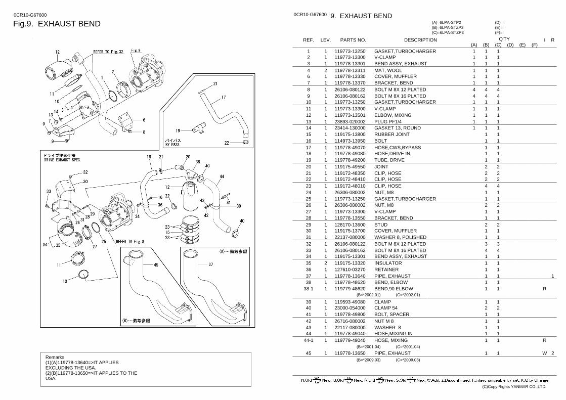
Fig.9. EXHAUST BEND 0CR10-G67600
Remarks (1)(A)119778-13640=>IT APPLIES EXCLUDING THE USA. (2)(B)119778-13650=>IT APPLIES TO THE USA.
0CR10-G67600 9. EXHAUST BEND
(F)= (E)= (D)=
(C)=6LPA-STZP3 (B)=6LPA-STZP2 (A)=6LPA-STP2
LEV. REF. PARTS NO. DESCRIPTION R I Q'TY (F) (D) (C) (B) (A) (E)
GASKET,TURBOCHARGER 119773-13250 1 1 1 1 1 V-CLAMP 119773-13300 1 2 1 1 1 BEND ASSY, EXHAUST 119778-13301 1 3 1 1 1 MAT, WOOL 119778-13311 2 4 1 1 1 COVER, MUFFLER 119778-13330 1 6 1 1 1 BRACKET, BEND 119778-13370 1 7 1 1 1 BOLT M 8X 12 PLATED 26106-080122 1 8 4 4 4 BOLT M 8X 16 PLATED 26106-080162 1 9 4 4 4 GASKET,TURBOCHARGER 119773-13250 1 10 1 1 1 V-CLAMP 119773-13300 1 11 1 1 1 ELBOW, MIXING 119773-13501 1 12 1 1 1 PLUG PF1/4 23893-020002 1 13 1 1 1 GASKET 13, ROUND 23414-130000 1 14 1 1 1 RUBBER JOINT 119175-13800 1 15 1 1 BOLT 114973-13950 1 16 1 1 HOSE,CWS,BYPASS 119778-49070 1 17 1 1 HOSE,DRIVE IN 119778-49080 1 18 1 1 TUBE, DRIVE 119778-49200 1 19 1 1 JOINT 119175-49550 1 20 2 2 CLIP, HOSE 119172-48350 1 21 2 2 CLIP, HOSE 119172-48410 1 22 2 2 CLIP, HOSE 119172-48010 1 23 4 4 NUT, M8 26306-080002 1 24 1 1 GASKET,TURBOCHARGER 119773-13250 1 25 1 1 NUT, M8 26306-080002 1 26 2 2 V-CLAMP 119773-13300 1 27 1 1 BRACKET, BEND 119778-13550 1 28 1 1 STUD 128170-13600 1 29 2 2 COVER, MUFFLER 119175-13700 1 30 1 1 WASHER 8, POLISHED 22137-080000 1 31 1 1 BOLT M 8X 12 PLATED 26106-080122 1 32 3 3 BOLT M 8X 16 PLATED 26106-080162 1 33 4 4 BEND ASSY, EXHAUST 119175-13301 1 34 1 1 INSULATOR 119175-13320 2 35 1 1 RETAINER 127610-03270 1 36 1 1
1 PIPE, EXHAUST 119778-13640 1 37 1 1 BEND, ELBOW 119778-48620 1 38 1 1 BEND,90 ELBOW 119779-48620 1 38-1 R 1 1
(B=*2002.01) (C=*2002.01)
CLAMP 119593-49080 1 39 1 1 CLAMP 54 23000-054000 1 40 2 2 BOLT, SPACER 119778-49800 1 41 1 1 NUT M 8 26716-080002 1 42 1 1 WASHER 8 22117-080000 1 43 1 1 HOSE,MIXING IN 119778-49040 1 44 1 1 HOSE, MIXING 119779-49040 1 44-1 R 1 1
(B=*2001.04) (C=*2001.04) 2 PIPE, EXHAUST 119778-13650 1 45 W 1 1
(B=*2009.03) (C=*2009.03)
(C)Copy Rights YANMAR CO.,LTD.
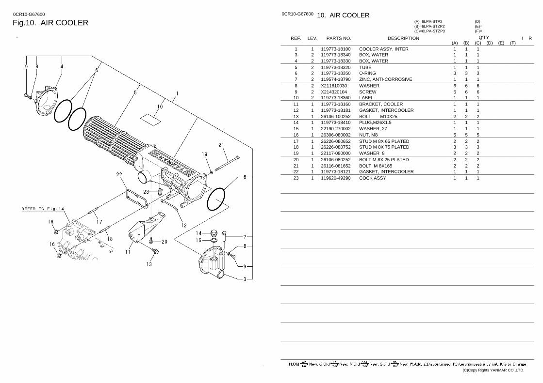
Fig.10. AIR COOLER 0CR10-G67600 0CR10-G67600 10. AIR COOLER
(F)= (E)= (D)=
(C)=6LPA-STZP3 (B)=6LPA-STZP2 (A)=6LPA-STP2
LEV. REF. PARTS NO. DESCRIPTION R I Q'TY (F) (D) (C) (B) (A) (E)
COOLER ASSY, INTER 119773-18100 1 1 1 1 1 BOX, WATER 119773-18340 2 3 1 1 1 BOX, WATER 119773-18330 2 4 1 1 1 TUBE 119773-18320 2 5 1 1 1 O-RING 119773-18350 2 6 3 3 3 ZINC, ANTI-CORROSIVE 119574-18790 2 7 1 1 1 WASHER X211810030 2 8 6 6 6 SCREW X214320104 2 9 6 6 6 LABEL 119773-18360 2 10 1 1 1 BRACKET, COOLER 119773-18160 1 11 1 1 1 GASKET, INTERCOOLER 119773-18181 1 12 1 1 1 BOLT M10X25 26136-100252 1 13 2 2 2 PLUG,M26X1.5 119773-18410 1 14 1 1 1 WASHER, 27 22190-270002 1 15 1 1 1 NUT, M8 26306-080002 1 16 5 5 5 STUD M 8X 65 PLATED 26226-080652 1 17 2 2 2 STUD M 8X 75 PLATED 26226-080752 1 18 3 3 3 WASHER 8 22117-080000 1 19 2 2 2 BOLT M 8X 25 PLATED 26106-080252 1 20 2 2 2 BOLT M 8X165 26116-081652 1 21 2 2 2 GASKET, INTERCOOLER 119773-18121 1 22 1 1 1 COCK ASSY 119620-49290 1 23 1 1 1
(C)Copy Rights YANMAR CO.,LTD.

Fig.11. AIR DUCT 0CR10-G67600 0CR10-G67600 11. AIR DUCT
(F)= (E)= (D)=
(C)=6LPA-STZP3 (B)=6LPA-STZP2 (A)=6LPA-STP2
LEV. REF. PARTS NO. DESCRIPTION R I Q'TY (F) (D) (C) (B) (A) (E)
DUCT, AIR 119773-18210 1 1 1 1 1 HOSE, AIR DUCT 119574-18250 1 2 1 1 1 V-CLAMP 119574-18700 1 3 1 1 1 GASKET (T/C OUT 119593-18800 1 4 1 1 1 CLAMP 119574-18910 1 5 2 2 2
(C)Copy Rights YANMAR CO.,LTD.
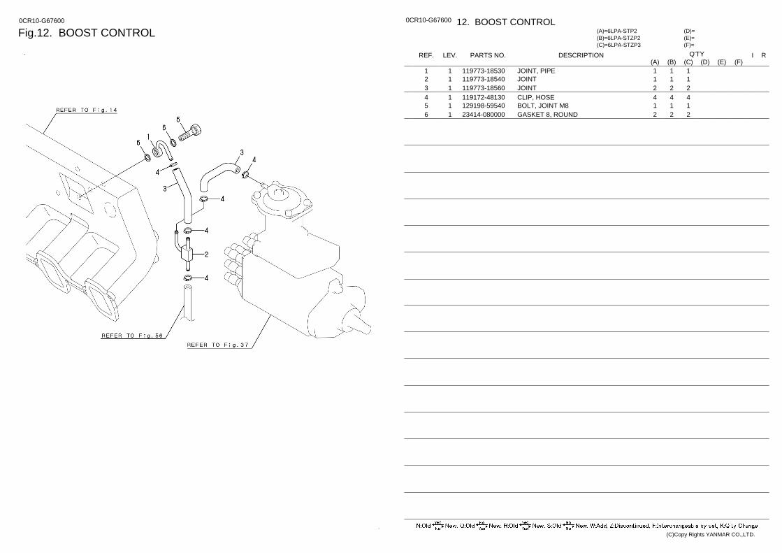
Fig.12. BOOST CONTROL 0CR10-G67600 0CR10-G67600 12. BOOST CONTROL
(F)= (E)= (D)=
(C)=6LPA-STZP3 (B)=6LPA-STZP2 (A)=6LPA-STP2
LEV. REF. PARTS NO. DESCRIPTION R I Q'TY (F) (D) (C) (B) (A) (E)
JOINT, PIPE 119773-18530 1 1 1 1 1 JOINT 119773-18540 1 2 1 1 1 JOINT 119773-18560 1 3 2 2 2 CLIP, HOSE 119172-48130 1 4 4 4 4 BOLT, JOINT M8 129198-59540 1 5 1 1 1 GASKET 8, ROUND 23414-080000 1 6 2 2 2
(C)Copy Rights YANMAR CO.,LTD.
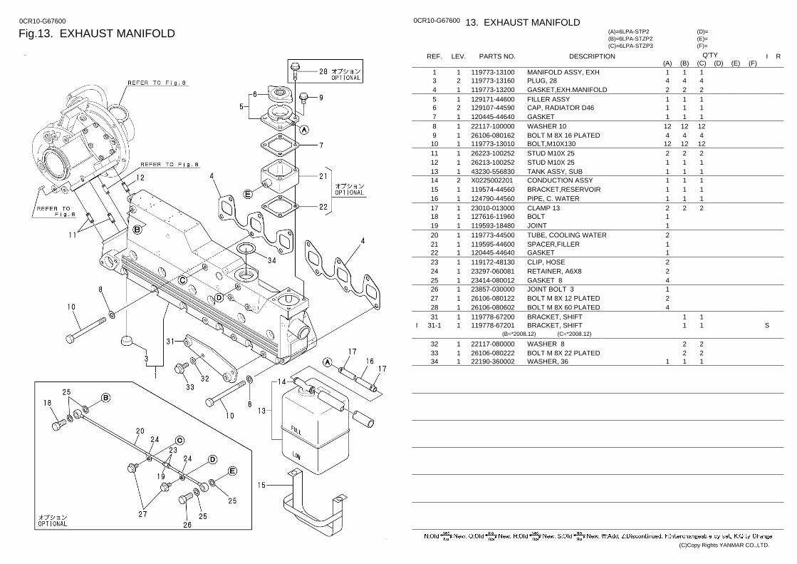
Fig.13. EXHAUST MANIFOLD 0CR10-G67600 0CR10-G67600 13. EXHAUST MANIFOLD
(F)= (E)= (D)=
(C)=6LPA-STZP3 (B)=6LPA-STZP2 (A)=6LPA-STP2
LEV. REF. PARTS NO. DESCRIPTION R I Q'TY (F) (D) (C) (B) (A) (E)
MANIFOLD ASSY, EXH 119773-13100 1 1 1 1 1 PLUG, 28 119773-13160 2 3 4 4 4 GASKET,EXH.MANIFOLD 119773-13200 1 4 2 2 2 FILLER ASSY 129171-44600 1 5 1 1 1 CAP, RADIATOR D46 129107-44590 2 6 1 1 1 GASKET 120445-44640 1 7 1 1 1 WASHER 10 22117-100000 1 8 12 12 12 BOLT M 8X 16 PLATED 26106-080162 1 9 4 4 4 BOLT,M10X130 119773-13010 1 10 12 12 12 STUD M10X 25 26223-100252 1 11 2 2 2 STUD M10X 25 26213-100252 1 12 1 1 1 TANK ASSY, SUB 43230-556830 1 13 1 1 1 CONDUCTION ASSY X0225002201 2 14 1 1 1 BRACKET,RESERVOIR 119574-44560 1 15 1 1 1 PIPE, C. WATER 124790-44560 1 16 1 1 1 CLAMP 13 23010-013000 1 17 2 2 2 BOLT 127616-11960 1 18 1 JOINT 119593-18480 1 19 1 TUBE, COOLING WATER 119773-44500 1 20 2 SPACER,FILLER 119595-44600 1 21 1 GASKET 120445-44640 1 22 1 CLIP, HOSE 119172-48130 1 23 2 RETAINER, A6X8 23297-060081 1 24 2 GASKET 8 23414-080012 1 25 4 JOINT BOLT 3 23857-030000 1 26 1 BOLT M 8X 12 PLATED 26106-080122 1 27 2 BOLT M 8X 60 PLATED 26106-080602 1 28 4 BRACKET, SHIFT 119778-67200 1 31 1 1 BRACKET, SHIFT 119778-67201 1 31-1 S 1 1 I
(B=*2008.12) (C=*2008.12)
WASHER 8 22117-080000 1 32 2 2 BOLT M 8X 22 PLATED 26106-080222 1 33 2 2 WASHER, 36 22190-360002 1 34 1 1 1
(C)Copy Rights YANMAR CO.,LTD.
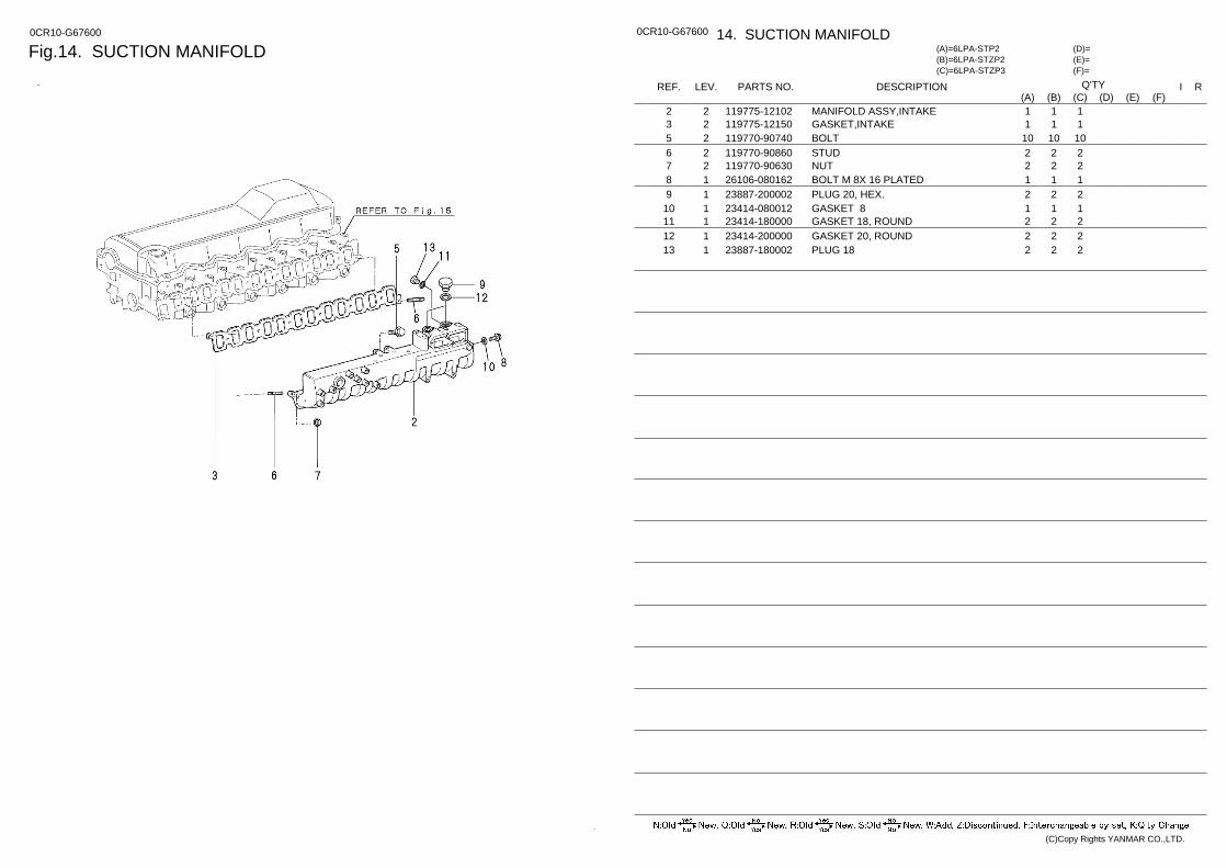
Fig.14. SUCTION MANIFOLD 0CR10-G67600 0CR10-G67600 14. SUCTION MANIFOLD
(F)= (E)= (D)=
(C)=6LPA-STZP3 (B)=6LPA-STZP2 (A)=6LPA-STP2
LEV. REF. PARTS NO. DESCRIPTION R I Q'TY (F) (D) (C) (B) (A) (E)
MANIFOLD ASSY,INTAKE 119775-12102 2 2 1 1 1 GASKET,INTAKE 119775-12150 2 3 1 1 1 BOLT 119770-90740 2 5 10 10 10 STUD 119770-90860 2 6 2 2 2 NUT 119770-90630 2 7 2 2 2 BOLT M 8X 16 PLATED 26106-080162 1 8 1 1 1 PLUG 20, HEX. 23887-200002 1 9 2 2 2 GASKET 8 23414-080012 1 10 1 1 1 GASKET 18, ROUND 23414-180000 1 11 2 2 2 GASKET 20, ROUND 23414-200000 1 12 2 2 2 PLUG 18 23887-180002 1 13 2 2 2
(C)Copy Rights YANMAR CO.,LTD.
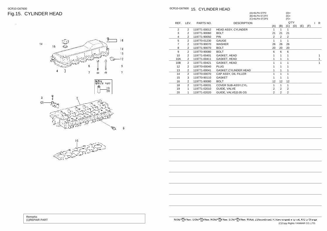
Fig.15. CYLINDER HEAD 0CR10-G67600
Remarks (1)REPAIR PART
0CR10-G67600 15. CYLINDER HEAD
(F)= (E)= (D)=
(C)=6LPA-STZP3 (B)=6LPA-STZP2 (A)=6LPA-STP2
LEV. REF. PARTS NO. DESCRIPTION R I Q'TY (F) (D) (C) (B) (A) (E)
HEAD ASSY, CYLINDER 119771-00012 2 2 1 1 1 BOLT 119771-90060 2 3 21 21 21 PIN 119771-90050 2 4 2 2 2 GAUGE 119770-01230 2 5 1 1 1 WASHER 119770-90070 2 7 26 26 26 BOLT 119771-90070 2 8 20 20 20 BOLT 119770-90080 2 9 6 6 6
1 GASKET, HEAD 119771-00401 2 10 1 1 1 1 GASKET, HEAD 119771-00411 2 10A 1 1 1 1 GASKET, HEAD 119771-00421 2 10B 1 1 1
PLUG 119770-00040 2 12 1 1 1 GASKET,CYLINDER HEAD 119771-00041 2 13 1 1 1 CAP ASSY, OIL FILLER 119770-00070 2 14 1 1 1 GASKET 119770-90110 3 15 1 1 1 BOLT 119771-90080 2 16 12 12 12 COVER SUB-ASSY,CYL. 119771-00031 2 18 1 1 1 GUIDE, VALVE 119771-02010 1 19 2 2 2 GUIDE, VALVE(0.05 OS 119771-02020 1 20 2 2 2
(C)Copy Rights YANMAR CO.,LTD.
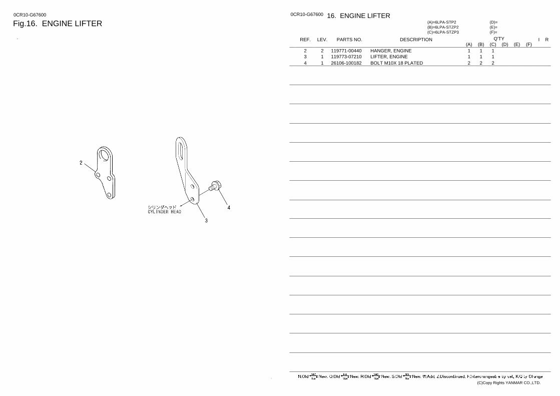
Fig.16. ENGINE LIFTER 0CR10-G67600 0CR10-G67600 16. ENGINE LIFTER
(F)= (E)= (D)=
(C)=6LPA-STZP3 (B)=6LPA-STZP2 (A)=6LPA-STP2
LEV. REF. PARTS NO. DESCRIPTION R I Q'TY (F) (D) (C) (B) (A) (E)
HANGER, ENGINE 119771-00440 2 2 1 1 1 LIFTER, ENGINE 119773-07210 1 3 1 1 1 BOLT M10X 18 PLATED 26106-100182 1 4 2 2 2
(C)Copy Rights YANMAR CO.,LTD.
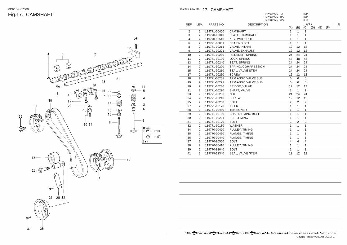
Fig.17. CAMSHAFT 0CR10-G67600 0CR10-G67600 17. CAMSHAFT
(F)= (E)= (D)=
(C)=6LPA-STZP3 (B)=6LPA-STZP2 (A)=6LPA-STP2
LEV. REF. PARTS NO. DESCRIPTION R I Q'TY (F) (D) (C) (B) (A) (E)
CAMSHAFT 119771-00450 2 2 1 1 1 PLATE, CAMSHAFT 119770-00340 2 3 1 1 1 KEY, WOODRUFF 119770-90510 2 4 1 1 1 BEARING SET 119771-00051 2 6 1 1 1 VALVE, INTAKE 119771-00211 2 8 12 12 12 VALVE, EXHAUST 119771-00221 2 9 12 12 12 RETAINER, SPRING 119771-00230 2 10 24 24 24 LOCK, SPRING 119771-90190 2 11 48 48 48 SEAT, SPRING 119771-00240 2 13 24 24 24 SPRING, COMPRESSION 119771-90200 2 14 24 24 24 SEAL, VALVE STEM 119771-90210 2 15 24 24 24 SCREW 119771-00250 2 17 12 12 12 ARM ASSY, VALVE SUB 119771-00261 2 18 6 6 6 ARM ASSY, VALVE SUB 119771-00271 2 19 6 6 6 BRIDGE, VALVE 119771-00280 2 20 12 12 12 SHAFT, VALVE 119771-00290 2 21 1 1 1 NUT 119771-90230 2 23 24 24 24 SCREW 119771-90240 2 24 12 12 12 BOLT 119771-90250 2 25 2 2 2 IDLER 119771-00170 2 27 1 1 1 TENSIONER 119771-00430 2 28 1 1 1 SHAFT, TIMING BELT 119771-00190 2 29 1 1 1 BELT,TIMING 119771-00201 2 30 1 1 1 BOLT 119771-90170 2 31 2 2 2 WASHER 119771-90180 2 32 1 1 1 PULLEY, TIMING 119770-00420 2 34 1 1 1 FLANGE, TIMING 119770-00430 2 35 1 1 1 FLANGE, TIMING 119770-00440 2 36 1 1 1 BOLT 119770-90560 2 37 4 4 4 PULLEY, TIMING 119770-00410 2 38 1 1 1 BOLT 119770-91040 2 39 1 1 1 SEAL, VALVE STEM 119775-11340 2 41 12 12 12
(C)Copy Rights YANMAR CO.,LTD.
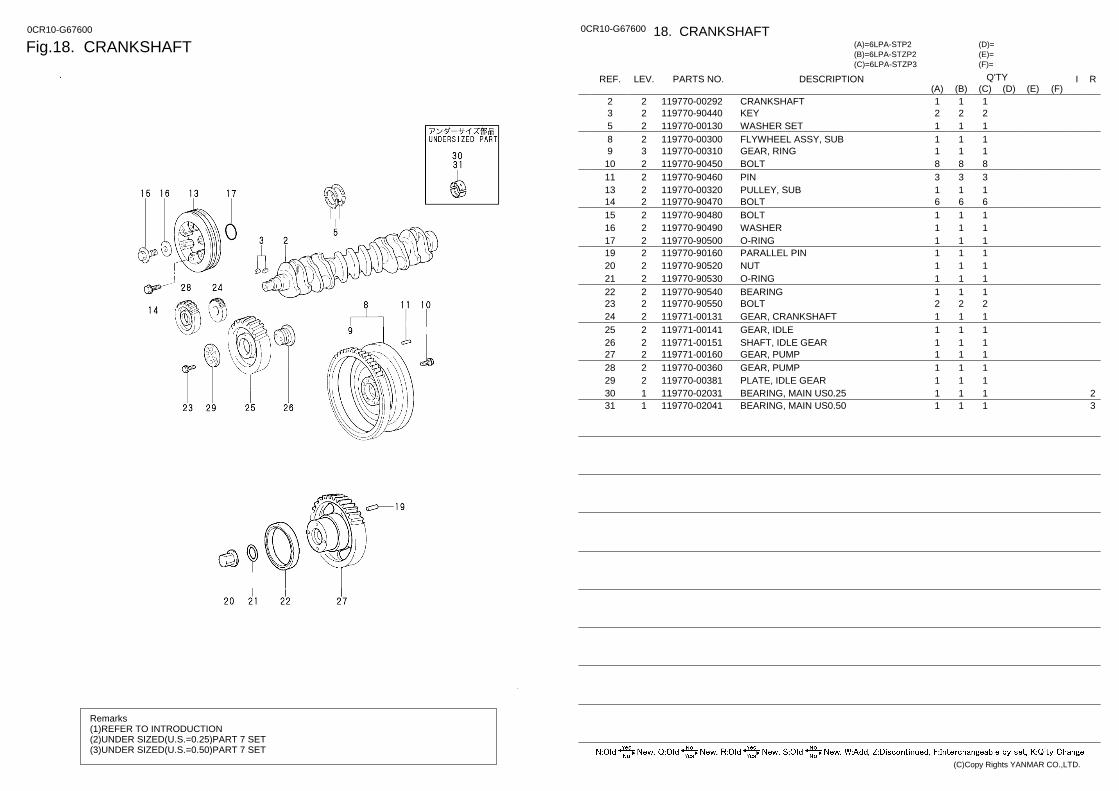
Fig.18. CRANKSHAFT 0CR10-G67600
Remarks (1)REFER TO INTRODUCTION (2)UNDER SIZED(U.S.=0.25)PART 7 SET (3)UNDER SIZED(U.S.=0.50)PART 7 SET
0CR10-G67600 18. CRANKSHAFT
(F)= (E)= (D)=
(C)=6LPA-STZP3 (B)=6LPA-STZP2 (A)=6LPA-STP2
LEV. REF. PARTS NO. DESCRIPTION R I Q'TY (F) (D) (C) (B) (A) (E)
CRANKSHAFT 119770-00292 2 2 1 1 1 KEY 119770-90440 2 3 2 2 2 WASHER SET 119770-00130 2 5 1 1 1 FLYWHEEL ASSY, SUB 119770-00300 2 8 1 1 1 GEAR, RING 119770-00310 3 9 1 1 1 BOLT 119770-90450 2 10 8 8 8 PIN 119770-90460 2 11 3 3 3 PULLEY, SUB 119770-00320 2 13 1 1 1 BOLT 119770-90470 2 14 6 6 6 BOLT 119770-90480 2 15 1 1 1 WASHER 119770-90490 2 16 1 1 1 O-RING 119770-90500 2 17 1 1 1 PARALLEL PIN 119770-90160 2 19 1 1 1 NUT 119770-90520 2 20 1 1 1 O-RING 119770-90530 2 21 1 1 1 BEARING 119770-90540 2 22 1 1 1 BOLT 119770-90550 2 23 2 2 2 GEAR, CRANKSHAFT 119771-00131 2 24 1 1 1 GEAR, IDLE 119771-00141 2 25 1 1 1 SHAFT, IDLE GEAR 119771-00151 2 26 1 1 1 GEAR, PUMP 119771-00160 2 27 1 1 1 GEAR, PUMP 119770-00360 2 28 1 1 1 PLATE, IDLE GEAR 119770-00381 2 29 1 1 1
2 BEARING, MAIN US0.25 119770-02031 1 30 1 1 1 3 BEARING, MAIN US0.50 119770-02041 1 31 1 1 1
(C)Copy Rights YANMAR CO.,LTD.
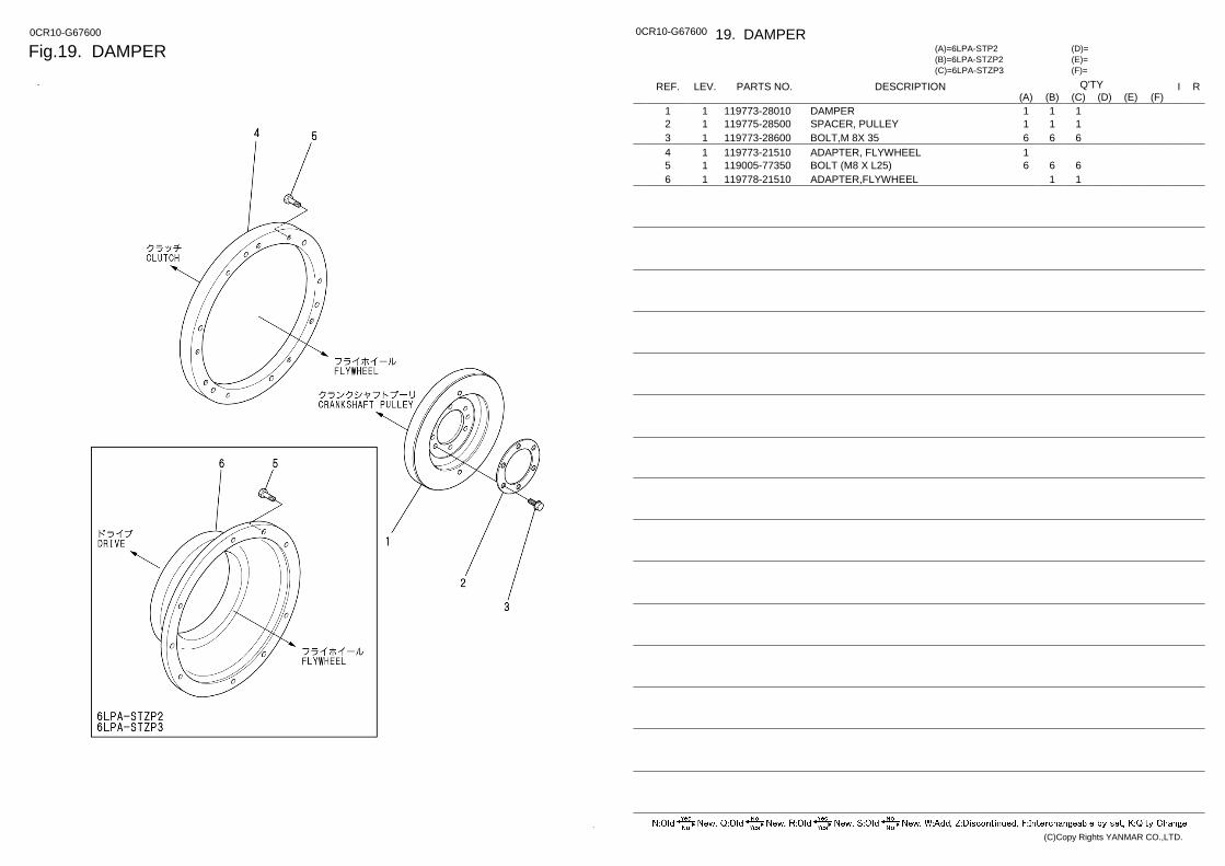
Fig.19. DAMPER 0CR10-G67600 0CR10-G67600 19. DAMPER
(F)= (E)= (D)=
(C)=6LPA-STZP3 (B)=6LPA-STZP2 (A)=6LPA-STP2
LEV. REF. PARTS NO. DESCRIPTION R I Q'TY (F) (D) (C) (B) (A) (E)
DAMPER 119773-28010 1 1 1 1 1 SPACER, PULLEY 119775-28500 1 2 1 1 1 BOLT,M 8X 35 119773-28600 1 3 6 6 6 ADAPTER, FLYWHEEL 119773-21510 1 4 1 BOLT (M8 X L25) 119005-77350 1 5 6 6 6 ADAPTER,FLYWHEEL 119778-21510 1 6 1 1
(C)Copy Rights YANMAR CO.,LTD.
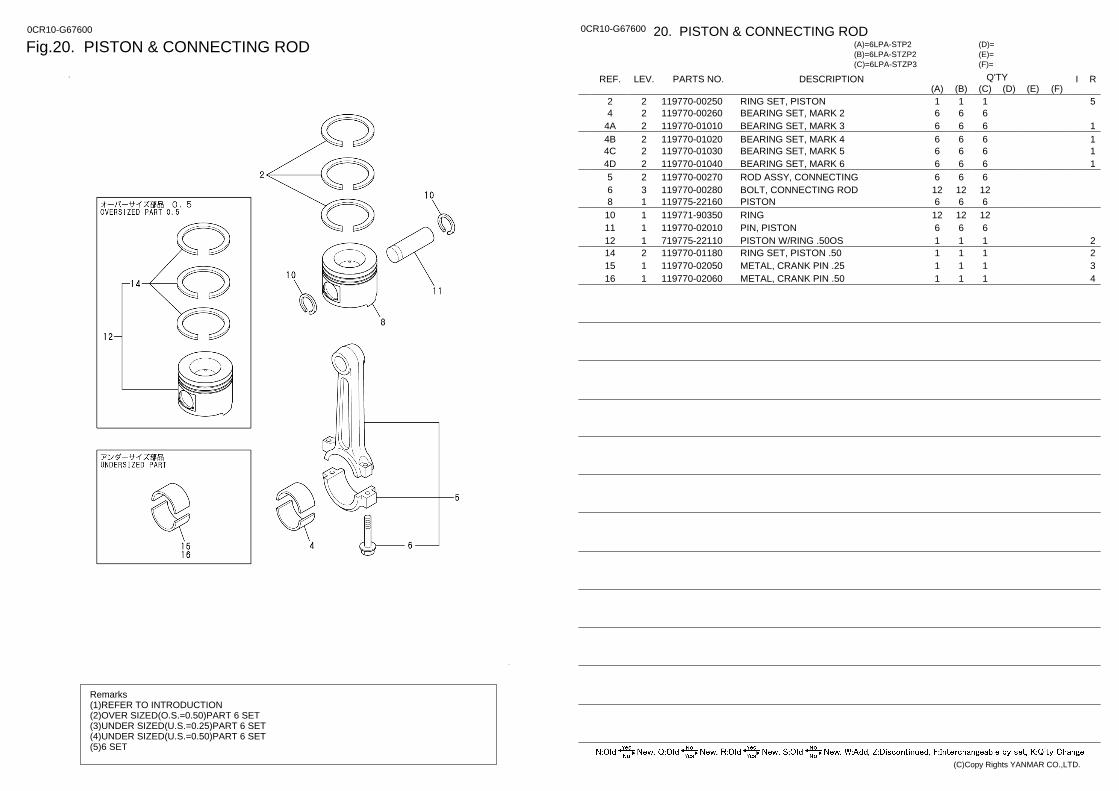
Fig.20. PISTON & CONNECTING ROD 0CR10-G67600
Remarks (1)REFER TO INTRODUCTION (2)OVER SIZED(O.S.=0.50)PART 6 SET (3)UNDER SIZED(U.S.=0.25)PART 6 SET (4)UNDER SIZED(U.S.=0.50)PART 6 SET (5)6 SET
0CR10-G67600 20. PISTON & CONNECTING ROD
(F)= (E)= (D)=
(C)=6LPA-STZP3 (B)=6LPA-STZP2 (A)=6LPA-STP2
LEV. REF. PARTS NO. DESCRIPTION R I Q'TY (F) (D) (C) (B) (A) (E)
5 RING SET, PISTON 119770-00250 2 2 1 1 1 BEARING SET, MARK 2 119770-00260 2 4 6 6 6
1 BEARING SET, MARK 3 119770-01010 2 4A 6 6 6 1 BEARING SET, MARK 4 119770-01020 2 4B 6 6 6 1 BEARING SET, MARK 5 119770-01030 2 4C 6 6 6 1 BEARING SET, MARK 6 119770-01040 2 4D 6 6 6
ROD ASSY, CONNECTING 119770-00270 2 5 6 6 6 BOLT, CONNECTING ROD 119770-00280 3 6 12 12 12 PISTON 119775-22160 1 8 6 6 6 RING 119771-90350 1 10 12 12 12 PIN, PISTON 119770-02010 1 11 6 6 6
2 PISTON W/RING .50OS 719775-22110 1 12 1 1 1 2 RING SET, PISTON .50 119770-01180 2 14 1 1 1 3 METAL, CRANK PIN .25 119770-02050 1 15 1 1 1 4 METAL, CRANK PIN .50 119770-02060 1 16 1 1 1
(C)Copy Rights YANMAR CO.,LTD.
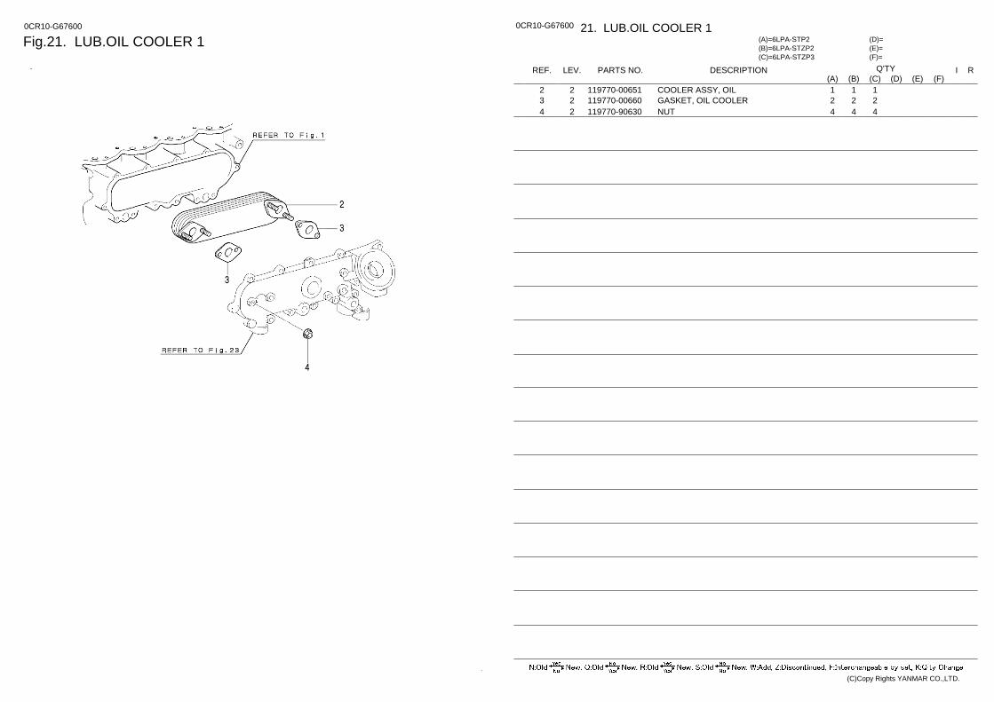
Fig.21. LUB.OIL COOLER 1 0CR10-G67600 0CR10-G67600 21. LUB.OIL COOLER 1
(F)= (E)= (D)=
(C)=6LPA-STZP3 (B)=6LPA-STZP2 (A)=6LPA-STP2
LEV. REF. PARTS NO. DESCRIPTION R I Q'TY (F) (D) (C) (B) (A) (E)
COOLER ASSY, OIL 119770-00651 2 2 1 1 1 GASKET, OIL COOLER 119770-00660 2 3 2 2 2 NUT 119770-90630 2 4 4 4 4
(C)Copy Rights YANMAR CO.,LTD.
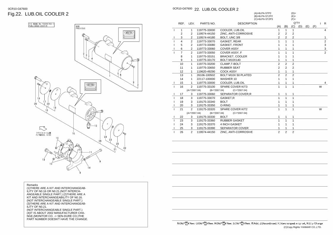
Fig.22. LUB.OIL COOLER 2 0CR10-G67600
Remarks (1)THERE ARE A KIT AND INTERCHANGEAB- ILITY OF N0.16 OR N0.21.(NOT INTERCH- ANGEABLE SINGLE PART.) (2)THERE ARE A KIT AND INTERCHANGEABILITY OF N0.16. (NOT INTERCHANGEABLE SINGLE PART.) (3)THERE ARE A KIT AND INTERCHANGEAB- ILITY OF N0.21. (NOT INTERCHANGEABLE SINGLE PART.) (4)IT IS ABOUT 2002 MANUFACTURER CHA- NGE.(MONITOR CO. -> SEN-DURE CO.)THE PART NUMBER DOESN'T HAVE THE CHANGE.
0CR10-G67600 22. LUB.OIL COOLER 2
(F)= (E)= (D)=
(C)=6LPA-STZP3 (B)=6LPA-STZP2 (A)=6LPA-STP2
LEV. REF. PARTS NO. DESCRIPTION R I Q'TY (F) (D) (C) (B) (A) (E)
4 COOLER, LUB.OIL 119775-33000 1 1 1 1 1 I ZINC, ANTI-CORROSIVE 119574-44150 2 2 2 2 2
1 BOLT, UNC 3/8 119574-44180 2 3 2 2 2 I 2 GASKET, REAR 119773-33070 2 4 1 1 1 I 3 GASKET, FRONT 119773-33080 2 5 1 1 1 I 3 COVER ASSY 119773-33060 2 6 1 1 1 I 2 COVER ASSY, F 119773-33050 2 7 1 1 1 I
BRACKET, COOLER 119775-33151 1 8 1 1 1 BOLT.M10X140 119775-33170 1 9 1 1 1 CLAMP,T-BOLT 119775-33200 1 10 2 2 2 RUBBER SEAT 119775-33650 1 11 2 2 2 COCK ASSY 119620-49290 1 12 1 1 1 BOLT M10X 50 PLATED 26106-100502 1 13 2 2 2 WASHER 10 22117-100000 1 14 1 1 1
4 COOLER, LUB.OIL 119775-33000 1 15 1 1 1 I SPARE COVER KIT3 119775-33100 2 16 W 1 1 1 I
(A=*2007.04) (B=*2007.04) (C=*2007.04) SEPARATOR COVER,R 119775-33060 3 17 1 1 1 I GASKET,R 119775-33070 3 18 1 1 1 I BOLT 119175-33340 3 19 1 1 1 I O-RING 119175-33350 3 20 1 1 1 I SPARE COVER KIT2 119175-33320 2 21 W 1 1 1 I
(A=*2007.04) (B=*2007.04) (C=*2007.04) BOLT 119175-33330 3 22 1 1 1 I RUBBER GASKET 119175-33360 3 23 1 1 1 I 4 INCH GASKET 119175-33370 3 24 1 1 1 I SEPARATOR COVER 119175-33390 3 25 1 1 1 I ZINC, ANTI-CORROSIVE 119574-44150 2 26 2 2 2 I
(C)Copy Rights YANMAR CO.,LTD.

Fig.23. LUB.OIL COOLER COVER 0CR10-G67600 0CR10-G67600 23. LUB.OIL COOLER COVER
(F)= (E)= (D)=
(C)=6LPA-STZP3 (B)=6LPA-STZP2 (A)=6LPA-STP2
LEV. REF. PARTS NO. DESCRIPTION R I Q'TY (F) (D) (C) (B) (A) (E)
FILTER, OIL 119770-90620 2 2 1 1 1 VALVE ASSY, SUB 119770-00670 2 5 1 1 1 VALVE ASSY, COOLER 119770-00680 2 8 1 1 1 COVER, COOLER 119770-00692 2 9 1 1 1 GASKET, OIL CLEANER 119770-00710 2 10 1 1 1 BOLT, FLANGE 119770-90260 2 11 12 12 12 O-RING, D80 119771-90260 2 13 1 1 1 NUT 119770-90630 2 15 2 2 2 PLUG 119770-90650 2 16 1 1 1 PLUG 119770-90660 2 17 1 1 1 GASKET 119770-90670 2 18 1 1 1 GASKET 119770-90680 2 19 1 1 1 GASKET 119770-90690 2 20 2 2 2 GASKET 119770-90700 2 21 1 1 1 PLUG 119770-90710 2 22 1 1 1 GASKET 119770-90720 2 23 1 1 1 PLUG 119770-90730 2 24 1 1 1 BOLT 119770-90740 2 25 2 2 2 STUD 119770-90750 2 26 2 2 2 UNION ASSY 119775-35080 2 28 1 1 1 SPACER 119775-35060 2 30 1 1 1
(C)Copy Rights YANMAR CO.,LTD.
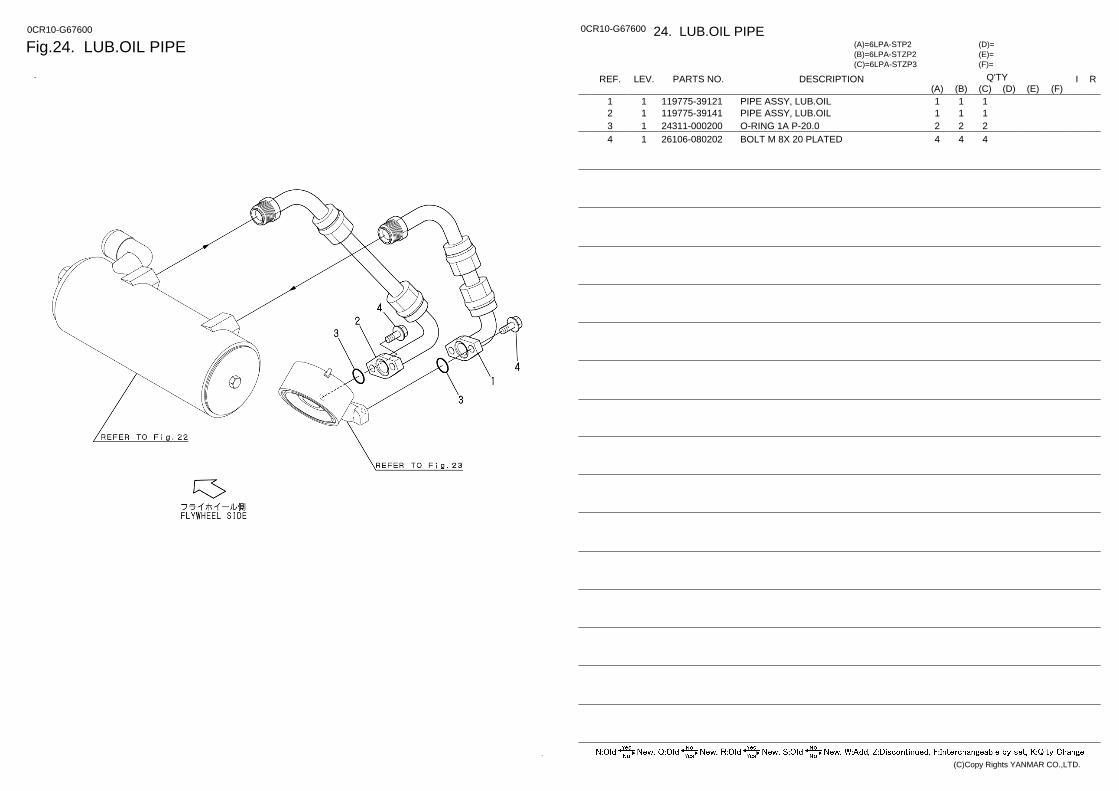
Fig.24. LUB.OIL PIPE 0CR10-G67600 0CR10-G67600 24. LUB.OIL PIPE
(F)= (E)= (D)=
(C)=6LPA-STZP3 (B)=6LPA-STZP2 (A)=6LPA-STP2
LEV. REF. PARTS NO. DESCRIPTION R I Q'TY (F) (D) (C) (B) (A) (E)
PIPE ASSY, LUB.OIL 119775-39121 1 1 1 1 1 PIPE ASSY, LUB.OIL 119775-39141 1 2 1 1 1 O-RING 1A P-20.0 24311-000200 1 3 2 2 2 BOLT M 8X 20 PLATED 26106-080202 1 4 4 4 4
(C)Copy Rights YANMAR CO.,LTD.
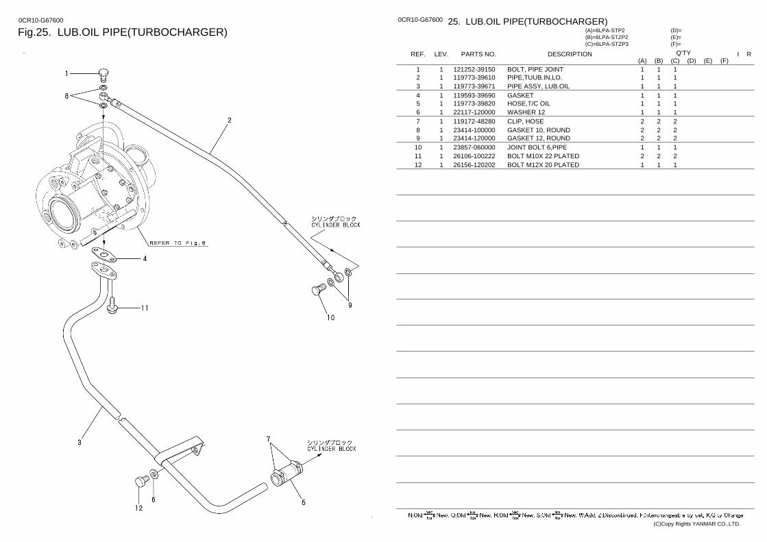
Fig.25. LUB.OIL PIPE(TURBOCHARGER) 0CR10-G67600 0CR10-G67600 25. LUB.OIL PIPE(TURBOCHARGER)
(F)= (E)= (D)=
(C)=6LPA-STZP3 (B)=6LPA-STZP2 (A)=6LPA-STP2
LEV. REF. PARTS NO. DESCRIPTION R I Q'TY (F) (D) (C) (B) (A) (E)
BOLT, PIPE JOINT 121252-39150 1 1 1 1 1 PIPE,TUUB.IN,LO. 119773-39610 1 2 1 1 1 PIPE ASSY, LUB.OIL 119773-39671 1 3 1 1 1 GASKET 119593-39690 1 4 1 1 1 HOSE,T/C OIL 119773-39820 1 5 1 1 1 WASHER 12 22117-120000 1 6 1 1 1 CLIP, HOSE 119172-48280 1 7 2 2 2 GASKET 10, ROUND 23414-100000 1 8 2 2 2 GASKET 12, ROUND 23414-120000 1 9 2 2 2 JOINT BOLT 6,PIPE 23857-060000 1 10 1 1 1 BOLT M10X 22 PLATED 26106-100222 1 11 2 2 2 BOLT M12X 20 PLATED 26156-120202 1 12 1 1 1
(C)Copy Rights YANMAR CO.,LTD.
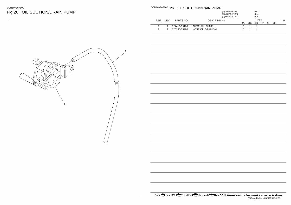
Fig.26. OIL SUCTION/DRAIN PUMP 0CR10-G67600 0CR10-G67600 26. OIL SUCTION/DRAIN PUMP
(F)= (E)= (D)=
(C)=6LPA-STZP3 (B)=6LPA-STZP2 (A)=6LPA-STP2
LEV. REF. PARTS NO. DESCRIPTION R I Q'TY (F) (D) (C) (B) (A) (E)
PUMP, OIL SUMP 124413-39100 1 1 1 1 1 HOSE,OIL DRAIN 3M 120130-39990 1 2 1 1 1
(C)Copy Rights YANMAR CO.,LTD.
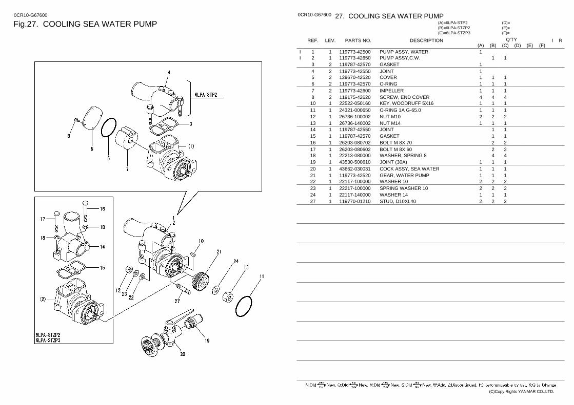
Fig.27. COOLING SEA WATER PUMP 0CR10-G67600 0CR10-G67600 27. COOLING SEA WATER PUMP
(F)= (E)= (D)=
(C)=6LPA-STZP3 (B)=6LPA-STZP2 (A)=6LPA-STP2
LEV. REF. PARTS NO. DESCRIPTION R I Q'TY (F) (D) (C) (B) (A) (E)
PUMP ASSY, WATER 119773-42500 1 1 1 I PUMP ASSY,C.W. 119773-42650 1 2 1 1 I GASKET 119787-42570 2 3 1 JOINT 119773-42550 2 4 1 COVER 129670-42520 2 5 1 1 1 O-RING 119773-42570 2 6 1 1 1 IMPELLER 119773-42600 2 7 1 1 1 SCREW, END COVER 119175-42620 2 8 4 4 4 KEY, WOODRUFF 5X16 22522-050160 1 10 1 1 1 O-RING 1A G-65.0 24321-000650 1 11 1 1 1 NUT M10 26736-100002 1 12 2 2 2 NUT M14 26736-140002 1 13 1 1 1 JOINT 119787-42550 1 14 1 1 GASKET 119787-42570 1 15 1 1 BOLT M 8X 70 26203-080702 1 16 2 2 BOLT M 8X 60 26203-080602 1 17 2 2 WASHER, SPRING 8 22213-080000 1 18 4 4 JOINT (30A) 43530-500610 1 19 1 1 1 COCK ASSY, SEA WATER 43662-030031 1 20 1 1 1 GEAR, WATER PUMP 119773-42520 1 21 1 1 1 WASHER 10 22117-100000 1 22 2 2 2 SPRING WASHER 10 22217-100000 1 23 2 2 2 WASHER 14 22117-140000 1 24 1 1 1 STUD, D10XL40 119770-01210 1 27 2 2 2
(C)Copy Rights YANMAR CO.,LTD.
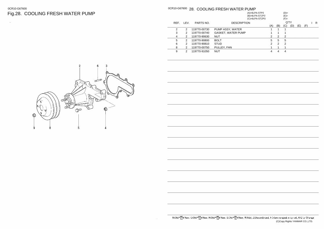
Fig.28. COOLING FRESH WATER PUMP 0CR10-G67600 0CR10-G67600 28. COOLING FRESH WATER PUMP
(F)= (E)= (D)=
(C)=6LPA-STZP3 (B)=6LPA-STZP2 (A)=6LPA-STP2
LEV. REF. PARTS NO. DESCRIPTION R I Q'TY (F) (D) (C) (B) (A) (E)
PUMP ASSY, WATER 119770-00730 2 2 1 1 1 GASKET, WATER PUMP 119770-00740 2 3 1 1 1 NUT 119770-90630 2 4 2 2 2 BOLT 119770-90800 2 5 5 5 5 STUD 119770-90810 2 6 2 2 2 PULLEY, FAN 119770-00750 2 8 1 1 1 NUT 119770-91050 2 9 4 4 4
(C)Copy Rights YANMAR CO.,LTD.
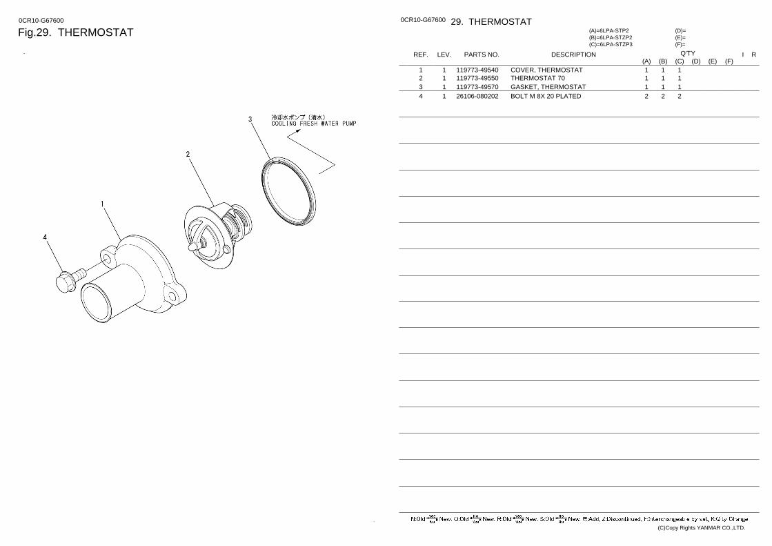
Fig.29. THERMOSTAT 0CR10-G67600 0CR10-G67600 29. THERMOSTAT
(F)= (E)= (D)=
(C)=6LPA-STZP3 (B)=6LPA-STZP2 (A)=6LPA-STP2
LEV. REF. PARTS NO. DESCRIPTION R I Q'TY (F) (D) (C) (B) (A) (E)
COVER, THERMOSTAT 119773-49540 1 1 1 1 1 THERMOSTAT 70 119773-49550 1 2 1 1 1 GASKET, THERMOSTAT 119773-49570 1 3 1 1 1 BOLT M 8X 20 PLATED 26106-080202 1 4 2 2 2
(C)Copy Rights YANMAR CO.,LTD.
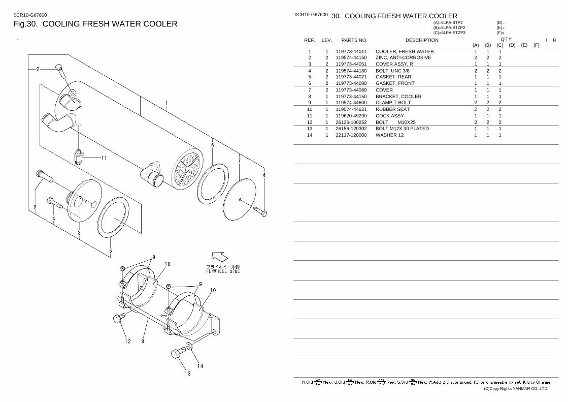
Fig.30. COOLING FRESH WATER COOLER 0CR10-G67600 0CR10-G67600 30. COOLING FRESH WATER COOLER
(F)= (E)= (D)=
(C)=6LPA-STZP3 (B)=6LPA-STZP2 (A)=6LPA-STP2
LEV. REF. PARTS NO. DESCRIPTION R I Q'TY (F) (D) (C) (B) (A) (E)
COOLER, FRESH WATER 119773-44011 1 1 1 1 1 ZINC, ANTI-CORROSIVE 119574-44150 2 2 2 2 2 COVER ASSY, R 119773-44051 2 3 1 1 1 BOLT, UNC 3/8 119574-44180 2 4 2 2 2 GASKET, REAR 119773-44071 2 5 1 1 1 GASKET, FRONT 119773-44080 2 6 1 1 1 COVER 119773-44060 2 7 1 1 1 BRACKET, COOLER 119773-44150 1 8 1 1 1 CLAMP,T-BOLT 119574-44600 1 9 2 2 2 RUBBER SEAT 119574-44621 1 10 2 2 2 COCK ASSY 119620-49290 1 11 1 1 1 BOLT M10X25 26136-100252 1 12 2 2 2 BOLT M12X 30 PLATED 26156-120302 1 13 1 1 1 WASHER 12 22117-120000 1 14 1 1 1
(C)Copy Rights YANMAR CO.,LTD.
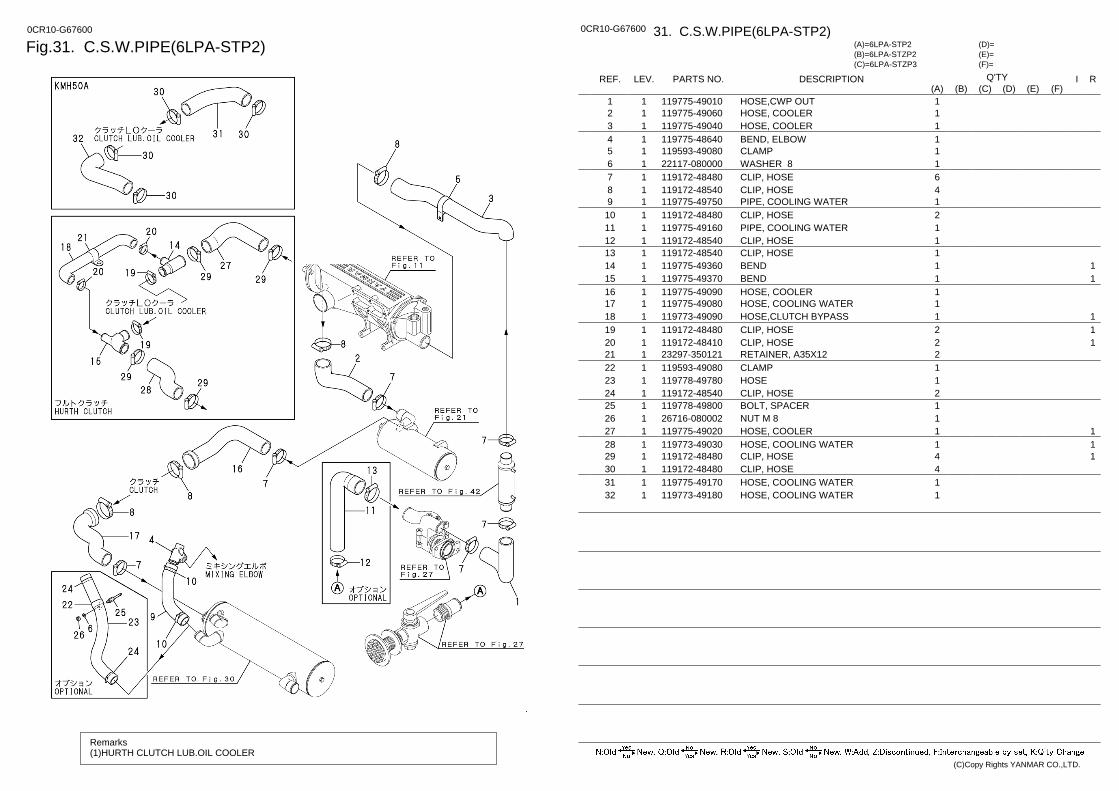
Fig.31. C.S.W.PIPE(6LPA-STP2) 0CR10-G67600
Remarks (1)HURTH CLUTCH LUB.OIL COOLER
0CR10-G67600 31. C.S.W.PIPE(6LPA-STP2)
(F)= (E)= (D)=
(C)=6LPA-STZP3 (B)=6LPA-STZP2 (A)=6LPA-STP2
LEV. REF. PARTS NO. DESCRIPTION R I Q'TY (F) (D) (C) (B) (A) (E)
HOSE,CWP OUT 119775-49010 1 1 1 HOSE, COOLER 119775-49060 1 2 1 HOSE, COOLER 119775-49040 1 3 1 BEND, ELBOW 119775-48640 1 4 1 CLAMP 119593-49080 1 5 1 WASHER 8 22117-080000 1 6 1 CLIP, HOSE 119172-48480 1 7 6 CLIP, HOSE 119172-48540 1 8 4 PIPE, COOLING WATER 119775-49750 1 9 1 CLIP, HOSE 119172-48480 1 10 2 PIPE, COOLING WATER 119775-49160 1 11 1 CLIP, HOSE 119172-48540 1 12 1 CLIP, HOSE 119172-48540 1 13 1
1 BEND 119775-49360 1 14 1 1 BEND 119775-49370 1 15 1
HOSE, COOLER 119775-49090 1 16 1 HOSE, COOLING WATER 119775-49080 1 17 1
1 HOSE,CLUTCH BYPASS 119773-49090 1 18 1 1 CLIP, HOSE 119172-48480 1 19 2 1 CLIP, HOSE 119172-48410 1 20 2
RETAINER, A35X12 23297-350121 1 21 2 CLAMP 119593-49080 1 22 1 HOSE 119778-49780 1 23 1 CLIP, HOSE 119172-48540 1 24 2 BOLT, SPACER 119778-49800 1 25 1 NUT M 8 26716-080002 1 26 1
1 HOSE, COOLER 119775-49020 1 27 1 1 HOSE, COOLING WATER 119773-49030 1 28 1 1 CLIP, HOSE 119172-48480 1 29 4
CLIP, HOSE 119172-48480 1 30 4 HOSE, COOLING WATER 119775-49170 1 31 1 HOSE, COOLING WATER 119773-49180 1 32 1
(C)Copy Rights YANMAR CO.,LTD.
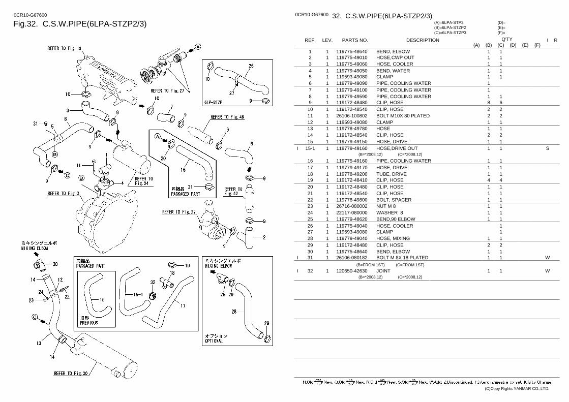
Fig.32. C.S.W.PIPE(6LPA-STZP2/3) 0CR10-G67600 0CR10-G67600 32. C.S.W.PIPE(6LPA-STZP2/3)
(F)= (E)= (D)=
(C)=6LPA-STZP3 (B)=6LPA-STZP2 (A)=6LPA-STP2
LEV. REF. PARTS NO. DESCRIPTION R I Q'TY (F) (D) (C) (B) (A) (E)
BEND, ELBOW 119775-48640 1 1 1 1 HOSE,CWP OUT 119775-49010 1 2 1 1 HOSE, COOLER 119775-49060 1 3 1 1 BEND, WATER 119779-49050 1 4 1 1 CLAMP 119593-49080 1 5 1 1 PIPE, COOLING WATER 119779-49090 1 6 1 PIPE, COOLING WATER 119779-49100 1 7 1 PIPE, COOLING WATER 119779-49590 1 8 1 1 CLIP, HOSE 119172-48480 1 9 6 8 CLIP, HOSE 119172-48540 1 10 2 2 BOLT M10X 80 PLATED 26106-100802 1 11 2 2 CLAMP 119593-49080 1 12 1 1 HOSE 119778-49780 1 13 1 1 CLIP, HOSE 119172-48540 1 14 2 2 HOSE, DRIVE 119779-49150 1 15 1 1 HOSE,DRIVE OUT 119779-49160 1 15-1 S 1 1 I
(B=*2008.12) (C=*2008.12) PIPE, COOLING WATER 119775-49160 1 16 1 1 HOSE, DRIVE 119779-49170 1 17 1 1 TUBE, DRIVE 119778-49200 1 18 1 1 CLIP, HOSE 119172-48410 1 19 4 4 CLIP, HOSE 119172-48480 1 20 1 1 CLIP, HOSE 119172-48540 1 21 1 1 BOLT, SPACER 119778-49800 1 22 1 1 NUT M 8 26716-080002 1 23 1 1 WASHER 8 22117-080000 1 24 1 1 BEND,90 ELBOW 119779-48620 1 25 1 1 HOSE, COOLER 119775-49040 1 26 1 CLAMP 119593-49080 1 27 1 HOSE, MIXING 119779-49040 1 28 1 1 CLIP, HOSE 119172-48480 1 29 2 2 BEND, ELBOW 119775-48640 1 30 1 1 BOLT M 8X 18 PLATED 26106-080182 1 31 W 1 1 I
(B=FROM 1ST) (C=FROM 1ST) JOINT 120650-42630 1 32 W 1 1 I
(B=*2008.12) (C=*2008.12)
(C)Copy Rights YANMAR CO.,LTD.
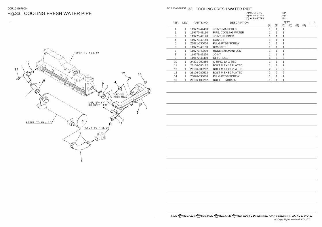
Fig.33. COOLING FRESH WATER PIPE 0CR10-G67600 0CR10-G67600 33. COOLING FRESH WATER PIPE
(F)= (E)= (D)=
(C)=6LPA-STZP3 (B)=6LPA-STZP2 (A)=6LPA-STP2
LEV. REF. PARTS NO. DESCRIPTION R I Q'TY (F) (D) (C) (B) (A) (E)
JOINT, MANIFOLD 119773-44450 1 1 1 1 1 PIPE, COOLING WATER 119773-49110 1 2 1 1 1 JOINT, RUBBER 119775-49120 1 3 1 1 1 GASKET 119773-49140 1 4 1 1 1 PLUG PT3/8,SCREW 23871-030000 1 5 1 1 1 BRACKET 119775-49150 1 6 1 1 1 HOSE,EXH.MANFOLD 119773-49200 1 7 1 1 1 JOINT 119775-49220 1 8 1 1 1 CLIP, HOSE 119172-48480 1 9 6 6 6 O-RING 1A G-35.0 24321-000350 1 10 1 1 1 BOLT M 8X 16 PLATED 26106-080162 1 11 1 1 1 BOLT M 8X 20 PLATED 26106-080202 1 12 2 2 2 BOLT M 8X 50 PLATED 26106-080502 1 13 2 2 2 PLUG PT3/8,SCREW 23876-030000 1 14 1 1 1 BOLT M10X25 26136-100252 1 15 1 1 1
(C)Copy Rights YANMAR CO.,LTD.
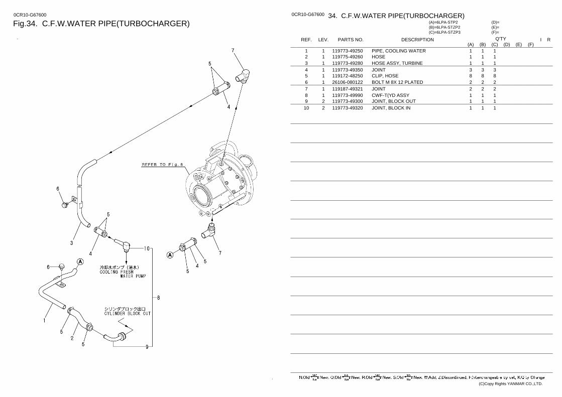
Fig.34. C.F.W.WATER PIPE(TURBOCHARGER) 0CR10-G67600 0CR10-G67600 34. C.F.W.WATER PIPE(TURBOCHARGER)
(F)= (E)= (D)=
(C)=6LPA-STZP3 (B)=6LPA-STZP2 (A)=6LPA-STP2
LEV. REF. PARTS NO. DESCRIPTION R I Q'TY (F) (D) (C) (B) (A) (E)
PIPE, COOLING WATER 119773-49250 1 1 1 1 1 HOSE 119775-49260 1 2 1 1 1 HOSE ASSY, TURBINE 119773-49280 1 3 1 1 1 JOINT 119773-49350 1 4 3 3 3 CLIP, HOSE 119172-48250 1 5 8 8 8 BOLT M 8X 12 PLATED 26106-080122 1 6 2 2 2 JOINT 119187-49321 1 7 2 2 2 CWF-T(YD ASSY 119773-49990 1 8 1 1 1 JOINT, BLOCK OUT 119773-49300 2 9 1 1 1 JOINT, BLOCK IN 119773-49320 2 10 1 1 1
(C)Copy Rights YANMAR CO.,LTD.
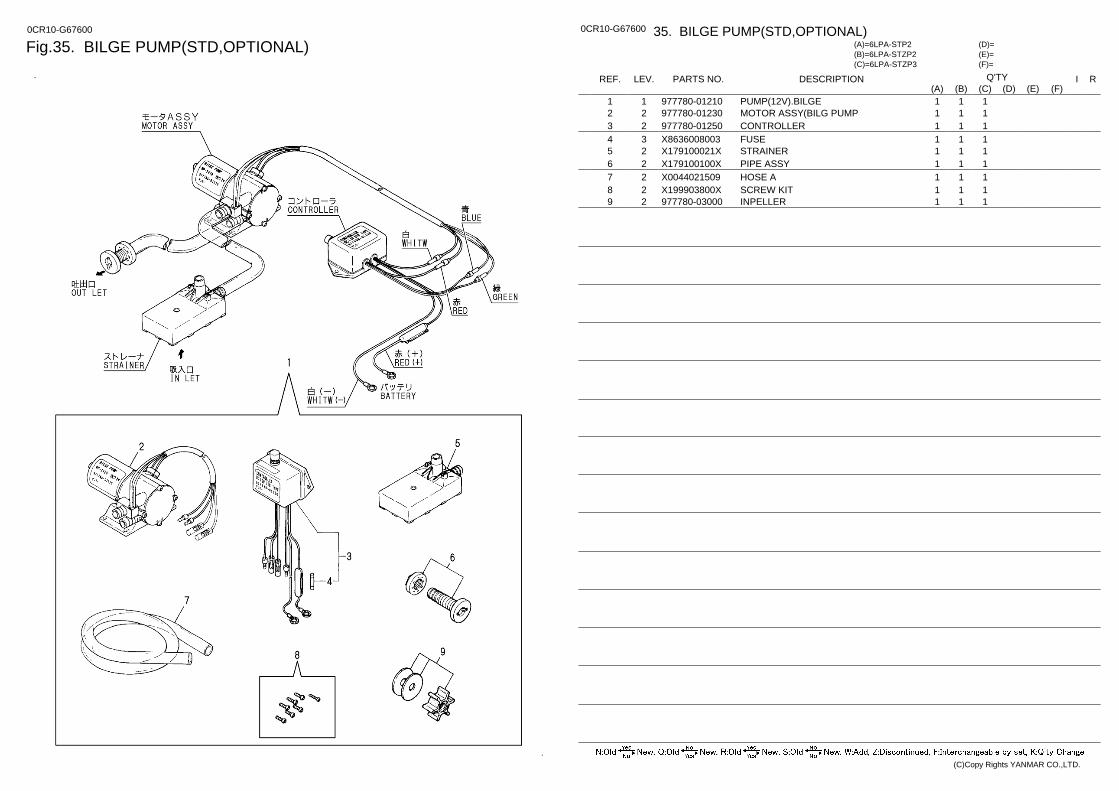
Fig.35. BILGE PUMP(STD,OPTIONAL) 0CR10-G67600 0CR10-G67600 35. BILGE PUMP(STD,OPTIONAL)
(F)= (E)= (D)=
(C)=6LPA-STZP3 (B)=6LPA-STZP2 (A)=6LPA-STP2
LEV. REF. PARTS NO. DESCRIPTION R I Q'TY (F) (D) (C) (B) (A) (E)
PUMP(12V).BILGE 977780-01210 1 1 1 1 1 MOTOR ASSY(BILG PUMP 977780-01230 2 2 1 1 1 CONTROLLER 977780-01250 2 3 1 1 1 FUSE X8636008003 3 4 1 1 1 STRAINER X179100021X 2 5 1 1 1 PIPE ASSY X179100100X 2 6 1 1 1 HOSE A X0044021509 2 7 1 1 1 SCREW KIT X199903800X 2 8 1 1 1 INPELLER 977780-03000 2 9 1 1 1
(C)Copy Rights YANMAR CO.,LTD.
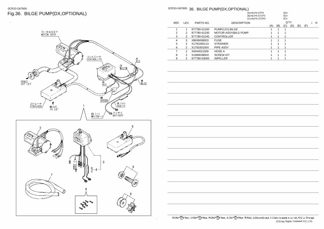
Fig.36. BILGE PUMP(DX,OPTIONAL) 0CR10-G67600 0CR10-G67600 36. BILGE PUMP(DX,OPTIONAL)
(F)= (E)= (D)=
(C)=6LPA-STZP3 (B)=6LPA-STZP2 (A)=6LPA-STP2
LEV. REF. PARTS NO. DESCRIPTION R I Q'TY (F) (D) (C) (B) (A) (E)
PUMP(12V).BILGE 977780-01200 1 1 1 1 1 MOTOR ASSY(BILG PUMP 977780-01230 2 2 1 1 1 CONTROLLER 977780-01240 2 3 1 1 1 FUSE X8636008003 3 4 1 1 1 STRAINER X179100011X 2 5 1 1 1 PIPE ASSY X179100100X 2 6 1 1 1 HOSE A X0044021509 2 7 1 1 1 SCREW KIT X199903800X 2 8 1 1 1 INPELLER 977780-03000 2 9 1 1 1
(C)Copy Rights YANMAR CO.,LTD.
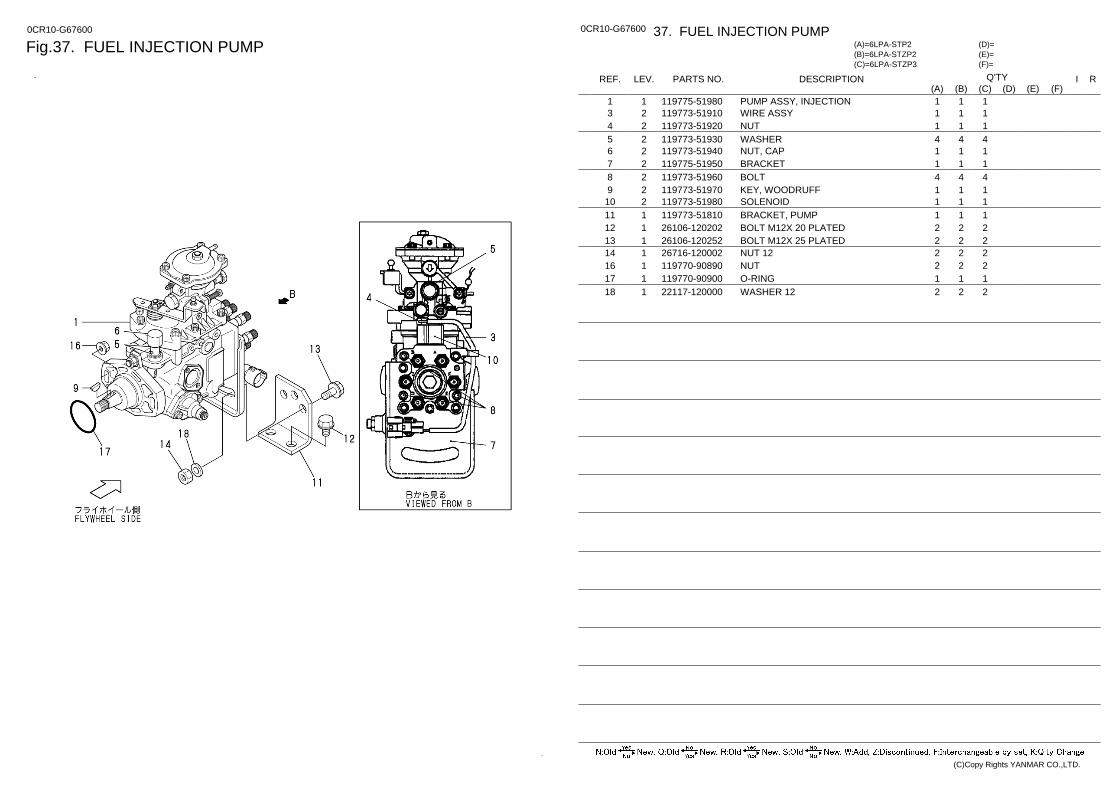
Fig.37. FUEL INJECTION PUMP 0CR10-G67600 0CR10-G67600 37. FUEL INJECTION PUMP
(F)= (E)= (D)=
(C)=6LPA-STZP3 (B)=6LPA-STZP2 (A)=6LPA-STP2
LEV. REF. PARTS NO. DESCRIPTION R I Q'TY (F) (D) (C) (B) (A) (E)
PUMP ASSY, INJECTION 119775-51980 1 1 1 1 1 WIRE ASSY 119773-51910 2 3 1 1 1 NUT 119773-51920 2 4 1 1 1 WASHER 119773-51930 2 5 4 4 4 NUT, CAP 119773-51940 2 6 1 1 1 BRACKET 119775-51950 2 7 1 1 1 BOLT 119773-51960 2 8 4 4 4 KEY, WOODRUFF 119773-51970 2 9 1 1 1 SOLENOID 119773-51980 2 10 1 1 1 BRACKET, PUMP 119773-51810 1 11 1 1 1 BOLT M12X 20 PLATED 26106-120202 1 12 2 2 2 BOLT M12X 25 PLATED 26106-120252 1 13 2 2 2 NUT 12 26716-120002 1 14 2 2 2 NUT 119770-90890 1 16 2 2 2 O-RING 119770-90900 1 17 1 1 1 WASHER 12 22117-120000 1 18 2 2 2
(C)Copy Rights YANMAR CO.,LTD.
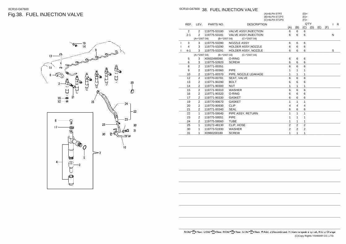
Fig.38. FUEL INJECTION VALVE 0CR10-G67600 0CR10-G67600 38. FUEL INJECTION VALVE
(F)= (E)= (D)=
(C)=6LPA-STZP3 (B)=6LPA-STZP2 (A)=6LPA-STP2
LEV. REF. PARTS NO. DESCRIPTION R I Q'TY (F) (D) (C) (B) (A) (E)
VALVE ASSY,INJECTION 119775-53180 2 2 6 6 6 VALVE ASSY,INJECTION 119775-53181 2 2-1 N 6 6 6
(A=*2007.04) (B=*2007.04) (C=*2007.04)
NOZZLE ASSY 119775-53280 3 3 6 6 6 I HOLDER ASSY,NOZZLE 119775-53290 3 4 6 6 6 I HOLDER ASSY, NOZZLE 119775-53291 3 4-1 S 6 6 6 I
(A=*2007.04) (B=*2007.04) (C=*2007.04) O-RING X0932490090 3 5 6 6 6 SCREW 119775-53920 3 6 6 6 6
119771-00351 2 8 6 6 6 PIPE 119771-00360 2 9 1 1 1 PIPE, NOZZLE LEAKAGE 119771-00370 2 10 1 1 1 SEAT, VALVE 119770-00781 2 12 6 6 6 BOLT 119771-90290 2 13 6 6 6 NUT 119771-90300 2 14 1 1 1 WASHER 119771-90310 2 15 6 6 6 O-RING 119771-90320 2 16 6 6 6 GASKET 119771-90330 2 17 6 6 6 GASKET 119770-90670 2 19 1 1 1 CLIP 119770-90930 2 20 4 4 4 SEAL 119771-00340 2 21 6 6 6 PIPE ASSY, RETURN 119775-59540 1 22 1 1 1 PIPE 119775-59551 2 23 1 1 1 TUBE 119775-59560 2 24 1 1 1 CLIP, HOSE 119172-48130 1 25 2 2 2 WASHER 119773-51930 1 30 2 2 2 SCREW X0960200180 1 31 1 1 1
(C)Copy Rights YANMAR CO.,LTD.
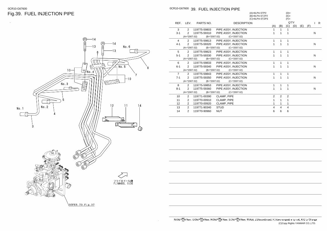
Fig.39. FUEL INJECTION PIPE 0CR10-G67600 0CR10-G67600 39. FUEL INJECTION PIPE
(F)= (E)= (D)=
(C)=6LPA-STZP3 (B)=6LPA-STZP2 (A)=6LPA-STP2
LEV. REF. PARTS NO. DESCRIPTION R I Q'TY (F) (D) (C) (B) (A) (E)
PIPE ASSY, INJECTION 119775-59803 2 3 1 1 1 PIPE ASSY, INJECTION 119775-59310 2 3-1 N 1 1 1
(A=*2007.02) (B=*2007.02) (C=*2007.02)
PIPE ASSY, INJECTION 119775-59813 2 4 1 1 1 PIPE ASSY, INJECTION 119775-59320 2 4-1 N 1 1 1
(A=*2007.02) (B=*2007.02) (C=*2007.02)
PIPE ASSY, INJECTION 119775-59823 2 5 1 1 1 PIPE ASSY, INJECTION 119775-59330 2 5-1 N 1 1 1
(A=*2007.02) (B=*2007.02) (C=*2007.02)
PIPE ASSY, INJECTION 119775-59833 2 6 1 1 1 PIPE ASSY, INJECTION 119775-59340 2 6-1 N 1 1 1
(A=*2007.02) (B=*2007.02) (C=*2007.02)
PIPE ASSY, INJECTION 119775-59843 2 7 1 1 1 PIPE ASSY, INJECTION 119775-59350 2 7-1 N 1 1 1
(A=*2007.02) (B=*2007.02) (C=*2007.02)
PIPE ASSY, INJECTION 119775-59853 2 8 1 1 1 PIPE ASSY, INJECTION 119775-59360 2 8-1 N 1 1 1
(A=*2007.02) (B=*2007.02) (C=*2007.02)
CLAMP, PIPE 119771-00390 2 10 2 2 2 CLAMP, PIPE 119770-00910 2 11 1 1 1 CLAMP, PIPE 119770-00920 2 12 1 1 1 STUD 119771-90340 2 13 4 4 4 NUT 119770-90960 2 14 6 6 6
(C)Copy Rights YANMAR CO.,LTD.
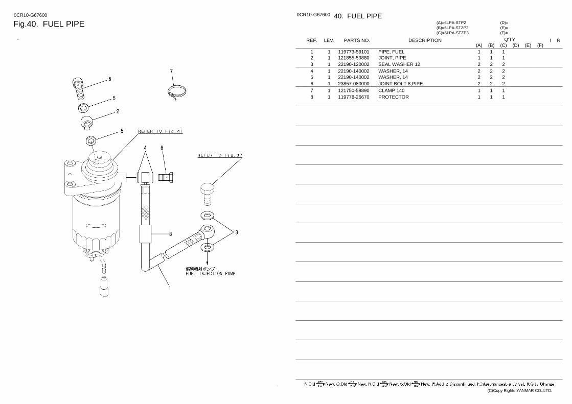
Fig.40. FUEL PIPE 0CR10-G67600 0CR10-G67600 40. FUEL PIPE
(F)= (E)= (D)=
(C)=6LPA-STZP3 (B)=6LPA-STZP2 (A)=6LPA-STP2
LEV. REF. PARTS NO. DESCRIPTION R I Q'TY (F) (D) (C) (B) (A) (E)
PIPE, FUEL 119773-59101 1 1 1 1 1 JOINT, PIPE 121855-59880 1 2 1 1 1 SEAL WASHER 12 22190-120002 1 3 2 2 2 WASHER, 14 22190-140002 1 4 2 2 2 WASHER, 14 22190-140002 1 5 2 2 2 JOINT BOLT 8,PIPE 23857-080000 1 6 2 2 2 CLAMP 140 121750-59890 1 7 1 1 1 PROTECTOR 119778-26670 1 8 1 1 1
(C)Copy Rights YANMAR CO.,LTD.
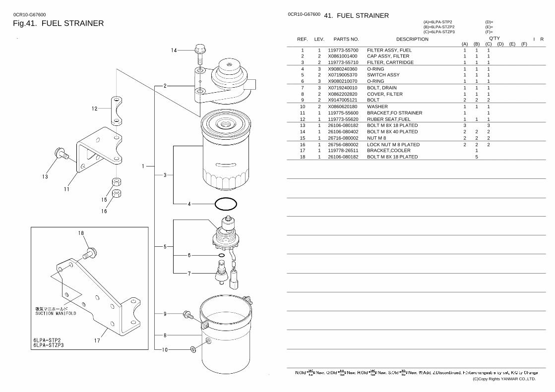
Fig.41. FUEL STRAINER 0CR10-G67600 0CR10-G67600 41. FUEL STRAINER
(F)= (E)= (D)=
(C)=6LPA-STZP3 (B)=6LPA-STZP2 (A)=6LPA-STP2
LEV. REF. PARTS NO. DESCRIPTION R I Q'TY (F) (D) (C) (B) (A) (E)
FILTER ASSY, FUEL 119773-55700 1 1 1 1 1 CAP ASSY, FILTER X0861001400 2 2 1 1 1 FILTER, CARTRIDGE 119773-55710 2 3 1 1 1 O-RING X9080240360 3 4 1 1 1 SWITCH ASSY X0719005370 2 5 1 1 1 O-RING X9080210070 3 6 1 1 1 BOLT, DRAIN X0719240010 3 7 1 1 1 COVER, FILTER X0862202820 2 8 1 1 1 BOLT X9147005121 2 9 2 2 2 WASHER X0860620180 2 10 1 1 1 BRACKET,FO STRAINER 119775-55600 1 11 1 1 RUBER SEAT,FUEL 119773-55620 1 12 1 1 1 BOLT M 8X 18 PLATED 26106-080182 1 13 3 3 BOLT M 8X 40 PLATED 26106-080402 1 14 2 2 2 NUT M 8 26716-080002 1 15 2 2 2 LOCK NUT M 8 PLATED 26756-080002 1 16 2 2 2 BRACKET,COOLER 119778-26511 1 17 1 BOLT M 8X 18 PLATED 26106-080182 1 18 5
(C)Copy Rights YANMAR CO.,LTD.
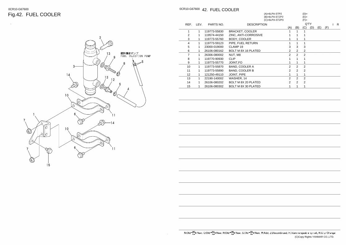
Fig.42. FUEL COOLER 0CR10-G67600 0CR10-G67600 42. FUEL COOLER
(F)= (E)= (D)=
(C)=6LPA-STZP3 (B)=6LPA-STZP2 (A)=6LPA-STP2
LEV. REF. PARTS NO. DESCRIPTION R I Q'TY (F) (D) (C) (B) (A) (E)
BRACKET, COOLER 119773-55830 1 1 1 1 1 ZINC, ANTI-CORROSIVE 119574-44150 1 2 1 1 1 BODY, COOLER 119773-55760 1 3 1 1 1 PIPE, FUEL RETURN 119773-59123 1 4 1 1 1 CLAMP 19 23000-019000 1 5 3 3 3 BOLT M 8X 16 PLATED 26106-080162 1 6 2 2 2 NUT, M8 26306-080002 1 7 2 2 2 CLIP 119770-90930 1 8 1 1 1 JOINT,FO 119773-55770 1 9 1 1 1 BAND, COOLER A 119773-55870 1 10 2 2 2 BAND, COOLER B 119773-55890 1 11 2 2 2 JOINT, PIPE 121250-49110 1 12 1 1 1 WASHER, 14 22190-140002 1 13 2 2 2 BOLT M 8X 20 PLATED 26106-080202 1 14 2 2 2 BOLT M 8X 30 PLATED 26106-080302 1 15 1 1 1
(C)Copy Rights YANMAR CO.,LTD.
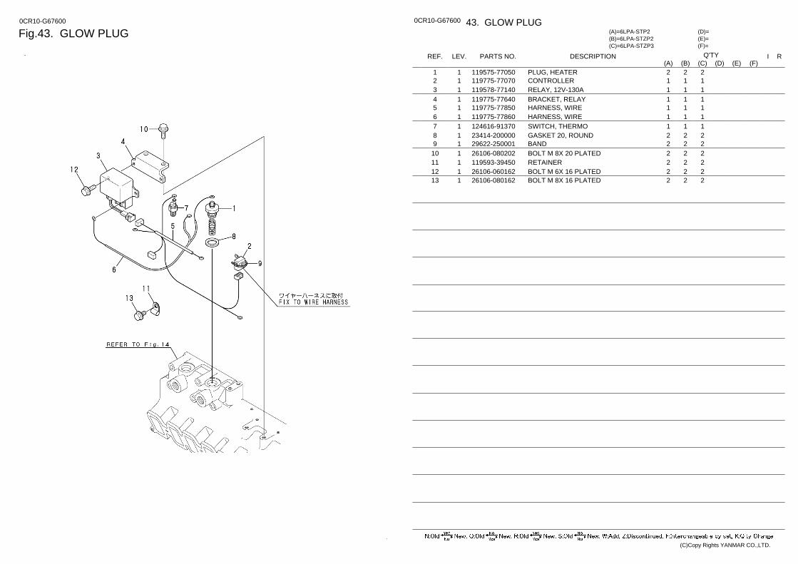
Fig.43. GLOW PLUG 0CR10-G67600 0CR10-G67600 43. GLOW PLUG
(F)= (E)= (D)=
(C)=6LPA-STZP3 (B)=6LPA-STZP2 (A)=6LPA-STP2
LEV. REF. PARTS NO. DESCRIPTION R I Q'TY (F) (D) (C) (B) (A) (E)
PLUG, HEATER 119575-77050 1 1 2 2 2 CONTROLLER 119775-77070 1 2 1 1 1 RELAY, 12V-130A 119578-77140 1 3 1 1 1 BRACKET, RELAY 119775-77640 1 4 1 1 1 HARNESS, WIRE 119775-77850 1 5 1 1 1 HARNESS, WIRE 119775-77860 1 6 1 1 1 SWITCH, THERMO 124616-91370 1 7 1 1 1 GASKET 20, ROUND 23414-200000 1 8 2 2 2 BAND 29622-250001 1 9 2 2 2 BOLT M 8X 20 PLATED 26106-080202 1 10 2 2 2 RETAINER 119593-39450 1 11 2 2 2 BOLT M 6X 16 PLATED 26106-060162 1 12 2 2 2 BOLT M 8X 16 PLATED 26106-080162 1 13 2 2 2
(C)Copy Rights YANMAR CO.,LTD.

Fig.44. CABLE BRACKET 0CR10-G67600 0CR10-G67600 44. CABLE BRACKET
(F)= (E)= (D)=
(C)=6LPA-STZP3 (B)=6LPA-STZP2 (A)=6LPA-STP2
LEV. REF. PARTS NO. DESCRIPTION R I Q'TY (F) (D) (C) (B) (A) (E)
SCREW M 5X 16 26022-050162 1 1 2 2 2 BRACKET, CABLE 119773-67101 1 2 1 1 1 ROD, CONTROL 119773-67150 1 3 1 1 1 LEVER ASSY, CONTROL 119773-67220 1 4 1 1 1 BOLT M 8X 30 PLATED 26106-080302 1 9 1 1 1 CLAMP 41710-000410 1 10 1 1 1 JOINT 41710-001300 1 11 1 1 1 REMOCON HEAD (MN 128170-86501 1 12 1 1 1 MT-3 REMO-CON 41730-000681 1 13 1 1 1 SPACER 127688-77340 1 14 1 1 1 CLAMP, CORD 160870-78700 1 15 1 1 1 BOLT M 8X 30 PLATED 26106-080302 1 16 1 1 1 SPRING WASHER 5 22217-050000 1 17 2 2 2
(C)Copy Rights YANMAR CO.,LTD.
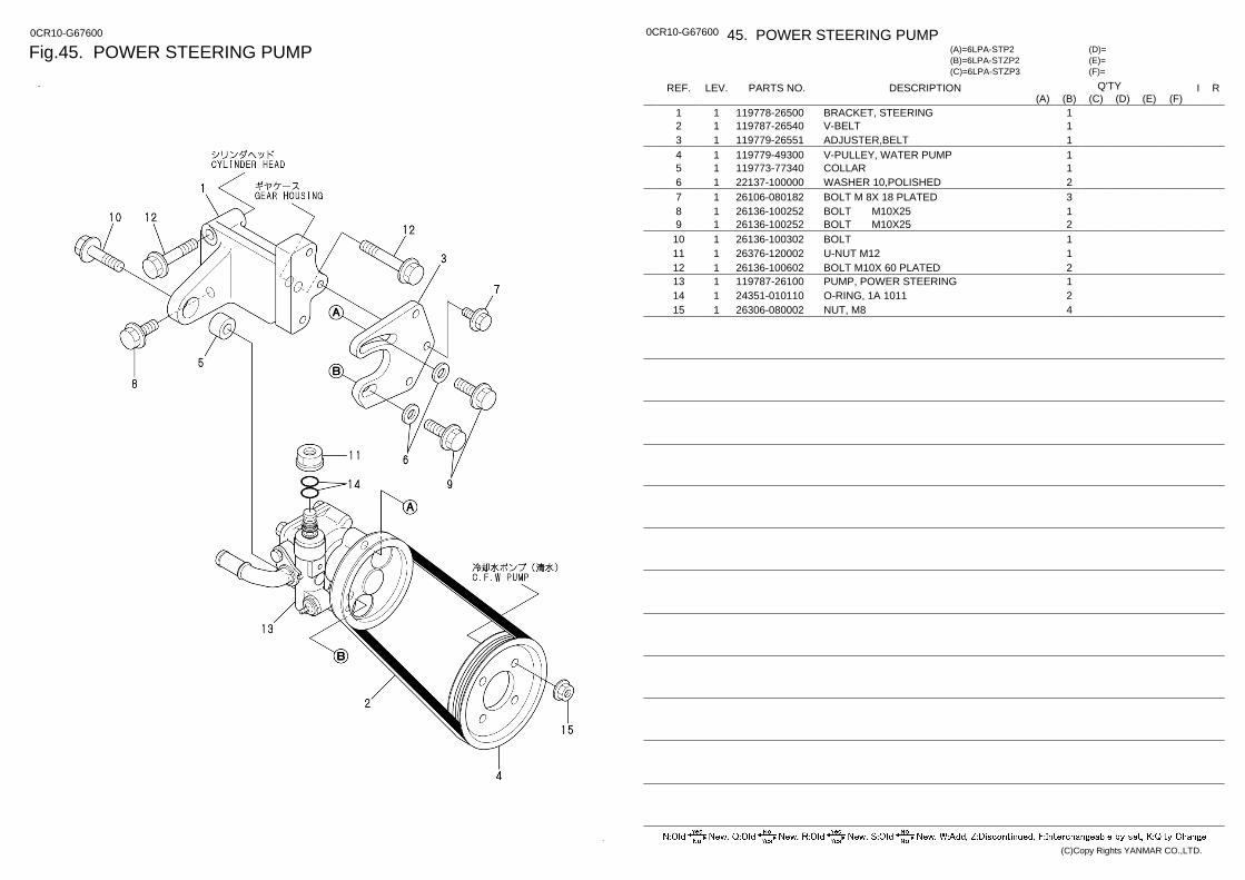
Fig.45. POWER STEERING PUMP 0CR10-G67600 0CR10-G67600 45. POWER STEERING PUMP
(F)= (E)= (D)=
(C)=6LPA-STZP3 (B)=6LPA-STZP2 (A)=6LPA-STP2
LEV. REF. PARTS NO. DESCRIPTION R I Q'TY (F) (D) (C) (B) (A) (E)
BRACKET, STEERING 119778-26500 1 1 1 V-BELT 119787-26540 1 2 1 ADJUSTER,BELT 119779-26551 1 3 1 V-PULLEY, WATER PUMP 119779-49300 1 4 1 COLLAR 119773-77340 1 5 1 WASHER 10,POLISHED 22137-100000 1 6 2 BOLT M 8X 18 PLATED 26106-080182 1 7 3 BOLT M10X25 26136-100252 1 8 1 BOLT M10X25 26136-100252 1 9 2 BOLT 26136-100302 1 10 1 U-NUT M12 26376-120002 1 11 1 BOLT M10X 60 PLATED 26136-100602 1 12 2 PUMP, POWER STEERING 119787-26100 1 13 1 O-RING, 1A 1011 24351-010110 1 14 2 NUT, M8 26306-080002 1 15 4
(C)Copy Rights YANMAR CO.,LTD.
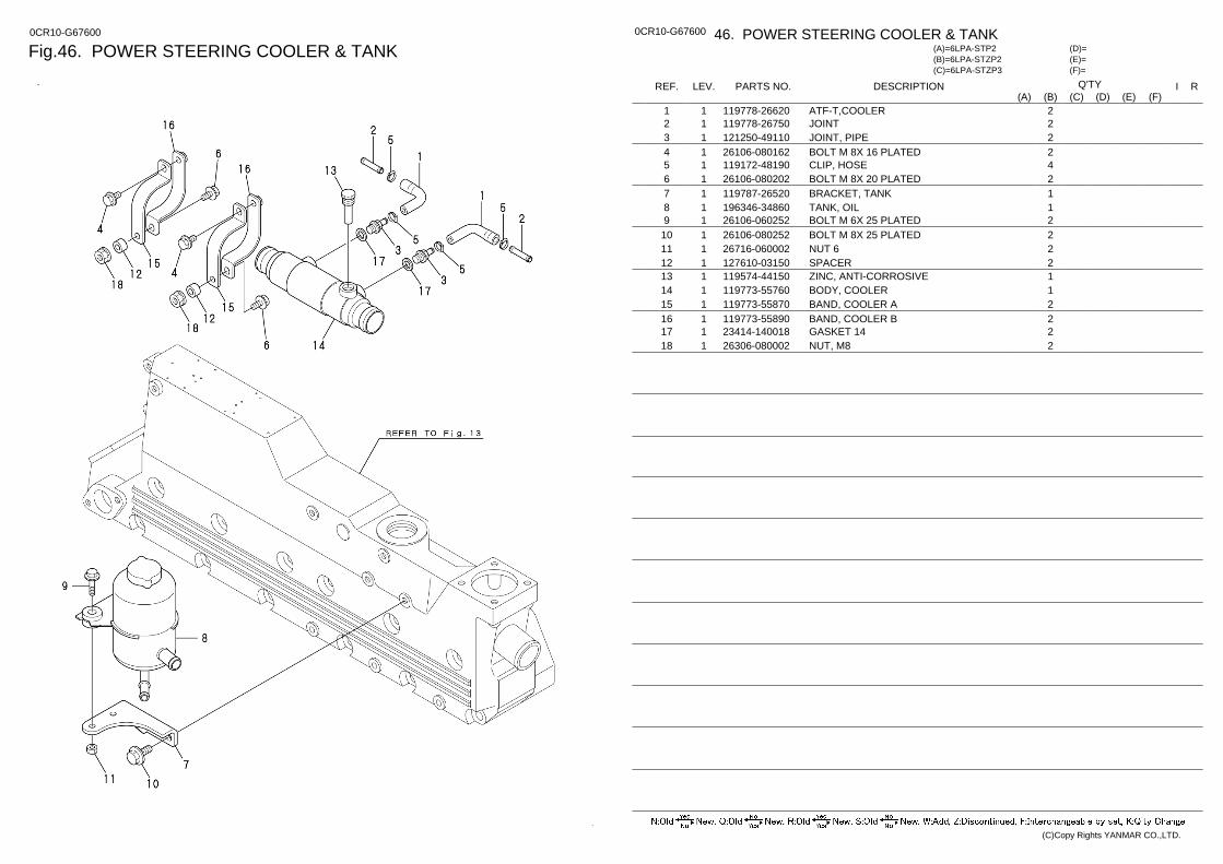
Fig.46. POWER STEERING COOLER & TANK 0CR10-G67600 0CR10-G67600 46. POWER STEERING COOLER & TANK
(F)= (E)= (D)=
(C)=6LPA-STZP3 (B)=6LPA-STZP2 (A)=6LPA-STP2
LEV. REF. PARTS NO. DESCRIPTION R I Q'TY (F) (D) (C) (B) (A) (E)
ATF-T,COOLER 119778-26620 1 1 2 JOINT 119778-26750 1 2 2 JOINT, PIPE 121250-49110 1 3 2 BOLT M 8X 16 PLATED 26106-080162 1 4 2 CLIP, HOSE 119172-48190 1 5 4 BOLT M 8X 20 PLATED 26106-080202 1 6 2 BRACKET, TANK 119787-26520 1 7 1 TANK, OIL 196346-34860 1 8 1 BOLT M 6X 25 PLATED 26106-060252 1 9 2 BOLT M 8X 25 PLATED 26106-080252 1 10 2 NUT 6 26716-060002 1 11 2 SPACER 127610-03150 1 12 2 ZINC, ANTI-CORROSIVE 119574-44150 1 13 1 BODY, COOLER 119773-55760 1 14 1 BAND, COOLER A 119773-55870 1 15 2 BAND, COOLER B 119773-55890 1 16 2 GASKET 14 23414-140018 1 17 2 NUT, M8 26306-080002 1 18 2
(C)Copy Rights YANMAR CO.,LTD.

Fig.47. ATF PIPE 0CR10-G67600 0CR10-G67600 47. ATF PIPE
(F)= (E)= (D)=
(C)=6LPA-STZP3 (B)=6LPA-STZP2 (A)=6LPA-STP2
LEV. REF. PARTS NO. DESCRIPTION R I Q'TY (F) (D) (C) (B) (A) (E)
PIPE 119778-26400 1 1 1 ATF-T(DRIVE-COOLER 119778-26410 1 2 1 CORRGATED TUBE 119778-26650 1 3 1 CLAMP 119778-26660 1 4 2 O-RING,INPUT-SIDE 119778-26700 1 5 1 O-RING,OUTPUT-SIDE 119778-26710 1 6 1 JOINT 119778-26800 1 7 1 RETAINER 119593-39450 1 8 2 BAND 250 194250-51660 1 9 2 ATF-T,COOLER-TANK 119787-26550 1 10 1 ATF-T(TANK-PUMP 119787-26561 1 11 1 PROTECTOR 119778-26670 1 12 2 BAND 250 194250-51660 1 13 2 CLIP, HOSE 119172-48190 1 14 3 CLIP, HOSE 119172-48250 1 15 2
(C)Copy Rights YANMAR CO.,LTD.
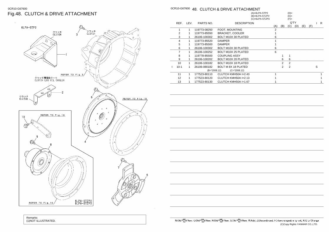
Fig.48. CLUTCH & DRIVE ATTACHMENT 0CR10-G67600
Remarks (1)NOT ILLUSTRATED.
0CR10-G67600 48. CLUTCH & DRIVE ATTACHMENT
(F)= (E)= (D)=
(C)=6LPA-STZP3 (B)=6LPA-STZP2 (A)=6LPA-STP2
LEV. REF. PARTS NO. DESCRIPTION R I Q'TY (F) (D) (C) (B) (A) (E)
FOOT, MOUNTING 119773-08250 1 1 2 BRACKET, COOLER 119773-85550 1 2 1 BOLT M10X 30 PLATED 26106-100302 1 3 6 DAMPER 119773-85520 1 4 1 DAMPER 119773-85500 1 5 1 BOLT M10X 30 PLATED 26106-100302 1 6 6 BOLT M10X 25 PLATED 26106-100252 1 7 6 COUPLING ASSY 119778-85500 1 8 1 1 BOLT M10X 20 PLATED 26106-100202 1 9 6 6 BOLT M10X 18 PLATED 26106-100182 1 10 2 2 BOLT M 8X 18 PLATED 26106-080182 1 10-1 S 2 2 I
(B=*2008.12) (C=*2008.12)
1 CLUTCH KMH50A I=2.43 177523-80110 1 11 1 1 CLUTCH KMH50A I=2.13 177523-80120 1 12 1 1 CLUTCH KMH50A I=1.67 177523-80130 1 13 1
(C)Copy Rights YANMAR CO.,LTD.
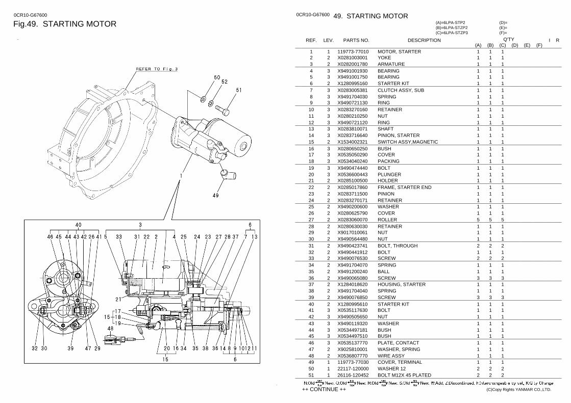
Fig.49. STARTING MOTOR 0CR10-G67600 0CR10-G67600 49. STARTING MOTOR
(F)= (E)= (D)=
(C)=6LPA-STZP3 (B)=6LPA-STZP2 (A)=6LPA-STP2
LEV. REF. PARTS NO. DESCRIPTION R I Q'TY (F) (D) (C) (B) (A) (E)
MOTOR, STARTER 119773-77010 1 1 1 1 1 YOKE X0281003001 2 2 1 1 1 ARMATURE X0282001780 2 3 1 1 1 BEARING X9491001930 3 4 1 1 1 BEARING X9491001750 3 5 1 1 1 STARTER KIT X1280995160 2 6 1 1 1 CLUTCH ASSY, SUB X0283005381 3 7 1 1 1 SPRING X9491704030 3 8 1 1 1 RING X9490721130 3 9 1 1 1 RETAINER X0283270160 3 10 1 1 1 NUT X0280210250 3 11 1 1 1 RING X9490721120 3 12 1 1 1 SHAFT X0283810071 3 13 1 1 1 PINION, STARTER X0283716640 3 14 1 1 1 SWITCH ASSY,MAGNETIC X1534002321 2 15 1 1 1 BUSH X0280650250 3 16 1 1 1 COVER X0535050290 3 17 1 1 1 PACKING X0534040240 3 18 1 1 1 BOLT X9490474440 3 19 1 1 1 PLUNGER X0536600443 3 20 1 1 1 HOLDER X0285100500 2 21 1 1 1 FRAME, STARTER END X0285017860 2 22 1 1 1 PINION X0283711500 2 23 1 1 1 RETAINER X0283270171 2 24 1 1 1 WASHER X9490200600 2 25 1 1 1 COVER X0280625790 2 26 1 1 1 ROLLER X0283060070 2 27 5 5 5 RETAINER X0280630030 2 28 1 1 1 NUT X9017010061 2 29 1 1 1 NUT X9490564480 2 30 1 1 1 BOLT, THROUGH X9490423741 2 31 2 2 2 BOLT X9490441912 2 32 1 1 1 SCREW X9490076530 2 33 2 2 2 SPRING X9491704070 2 34 1 1 1 BALL X9491200240 2 35 1 1 1 SCREW X9490065080 2 36 3 3 3 HOUSING, STARTER X1284018620 2 37 1 1 1 SPRING X9491704040 2 38 1 1 1 SCREW X9490076850 2 39 3 3 3 STARTER KIT X1280995610 2 40 1 1 1 BOLT X0535117630 3 41 1 1 1 NUT X9490505650 3 42 1 1 1 WASHER X9490119320 3 43 1 1 1 BUSH X0534497181 3 44 1 1 1 BUSH X0534497510 3 45 1 1 1 PLATE, CONTACT X0535137770 3 46 1 1 1 WASHER, SPRING X9025810001 2 47 1 1 1 WIRE ASSY X0536807770 2 48 1 1 1 COVER, TERMINAL 119773-77030 1 49 1 1 1 WASHER 12 22117-120000 1 50 2 2 2 BOLT M12X 45 PLATED 26116-120452 1 51 2 2 2
++ CONTINUE ++ (C)Copy Rights YANMAR CO.,LTD.
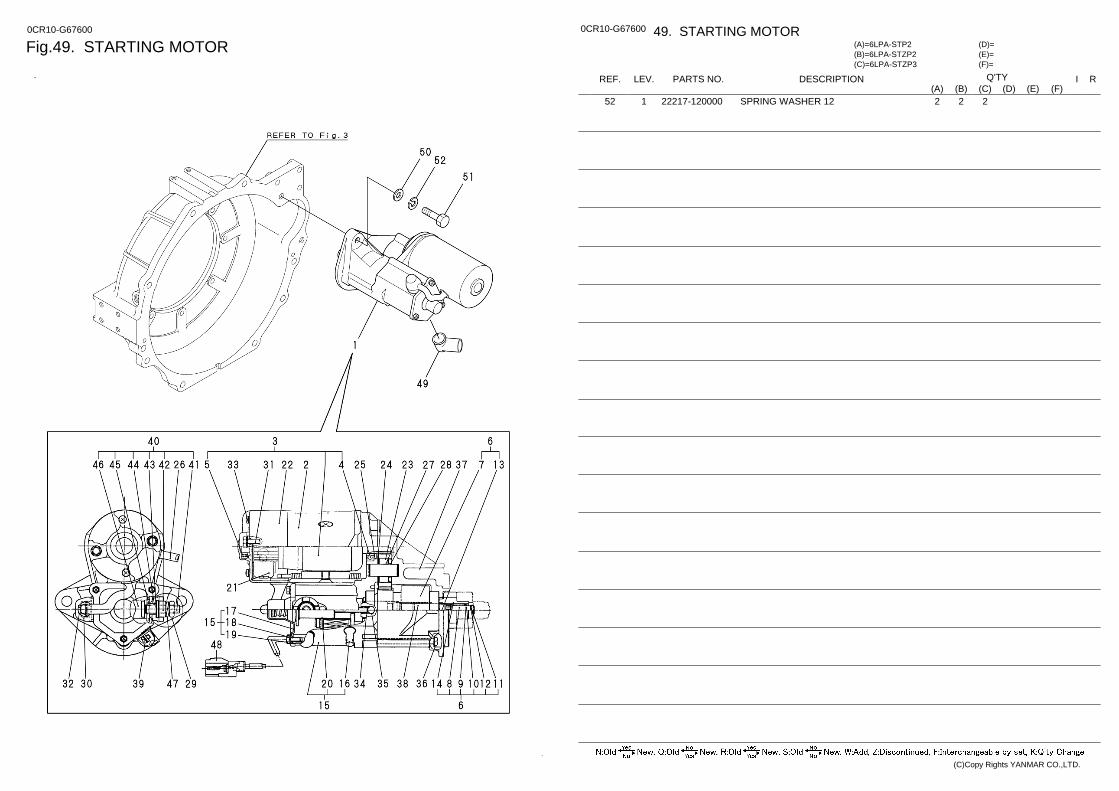
Fig.49. STARTING MOTOR 0CR10-G67600 0CR10-G67600 49. STARTING MOTOR
(F)= (E)= (D)=
(C)=6LPA-STZP3 (B)=6LPA-STZP2 (A)=6LPA-STP2
LEV. REF. PARTS NO. DESCRIPTION R I Q'TY (F) (D) (C) (B) (A) (E)
SPRING WASHER 12 22217-120000 1 52 2 2 2
(C)Copy Rights YANMAR CO.,LTD.
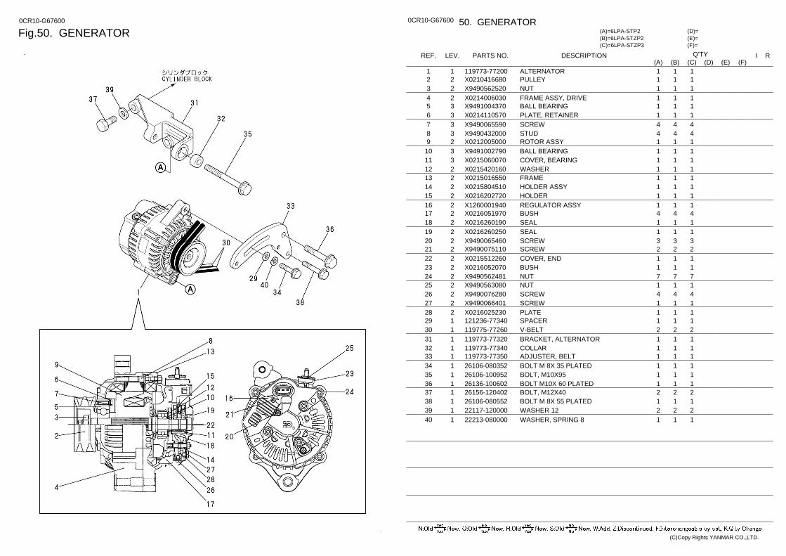
Fig.50. GENERATOR 0CR10-G67600 0CR10-G67600 50. GENERATOR
(F)= (E)= (D)=
(C)=6LPA-STZP3 (B)=6LPA-STZP2 (A)=6LPA-STP2
LEV. REF. PARTS NO. DESCRIPTION R I Q'TY (F) (D) (C) (B) (A) (E)
ALTERNATOR 119773-77200 1 1 1 1 1 PULLEY X0210416680 2 2 1 1 1 NUT X9490562520 2 3 1 1 1 FRAME ASSY, DRIVE X0214006030 2 4 1 1 1 BALL BEARING X9491004370 3 5 1 1 1 PLATE, RETAINER X0214110570 3 6 1 1 1 SCREW X9490065590 3 7 4 4 4 STUD X9490432000 3 8 4 4 4 ROTOR ASSY X0212005000 2 9 1 1 1 BALL BEARING X9491002790 3 10 1 1 1 COVER, BEARING X0215060070 3 11 1 1 1 WASHER X0215420160 2 12 1 1 1 FRAME X0215016550 2 13 1 1 1 HOLDER ASSY X0215804510 2 14 1 1 1 HOLDER X0216202720 2 15 1 1 1 REGULATOR ASSY X1260001940 2 16 1 1 1 BUSH X0216051970 2 17 4 4 4 SEAL X0216260190 2 18 1 1 1 SEAL X0216260250 2 19 1 1 1 SCREW X9490065460 2 20 3 3 3 SCREW X9490075110 2 21 2 2 2 COVER, END X0215512260 2 22 1 1 1 BUSH X0216052070 2 23 1 1 1 NUT X9490562481 2 24 7 7 7 NUT X9490563080 2 25 1 1 1 SCREW X9490076280 2 26 4 4 4 SCREW X9490066401 2 27 1 1 1 PLATE X0216025230 2 28 1 1 1 SPACER 121236-77340 1 29 1 1 1 V-BELT 119775-77260 1 30 2 2 2 BRACKET, ALTERNATOR 119773-77320 1 31 1 1 1 COLLAR 119773-77340 1 32 1 1 1 ADJUSTER, BELT 119773-77350 1 33 1 1 1 BOLT M 8X 35 PLATED 26106-080352 1 34 1 1 1 BOLT, M10X95 26106-100952 1 35 1 1 1 BOLT M10X 60 PLATED 26136-100602 1 36 1 1 1 BOLT, M12X40 26156-120402 1 37 2 2 2 BOLT M 8X 55 PLATED 26106-080552 1 38 1 1 1 WASHER 12 22117-120000 1 39 2 2 2 WASHER, SPRING 8 22213-080000 1 40 1 1 1
(C)Copy Rights YANMAR CO.,LTD.
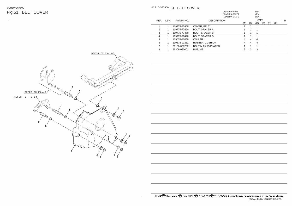
Fig.51. BELT COVER 0CR10-G67600 0CR10-G67600 51. BELT COVER
(F)= (E)= (D)=
(C)=6LPA-STZP3 (B)=6LPA-STZP2 (A)=6LPA-STP2
LEV. REF. PARTS NO. DESCRIPTION R I Q'TY (F) (D) (C) (B) (A) (E)
COVER, BELT 119775-77450 1 1 1 1 1 BOLT, SPACER A 119775-77460 1 2 1 1 1 BOLT, SPACER B 119775-77470 1 3 1 1 1 BOLT, SPACER D 119775-77490 1 4 1 1 1 COLLAR 119578-77680 1 5 4 4 4 RUBBER, CUSHION 119578-91351 1 6 4 4 4 BOLT M 8X 25 PLATED 26106-080252 1 7 1 1 1 NUT, M8 26306-080002 1 8 3 3 3
(C)Copy Rights YANMAR CO.,LTD.
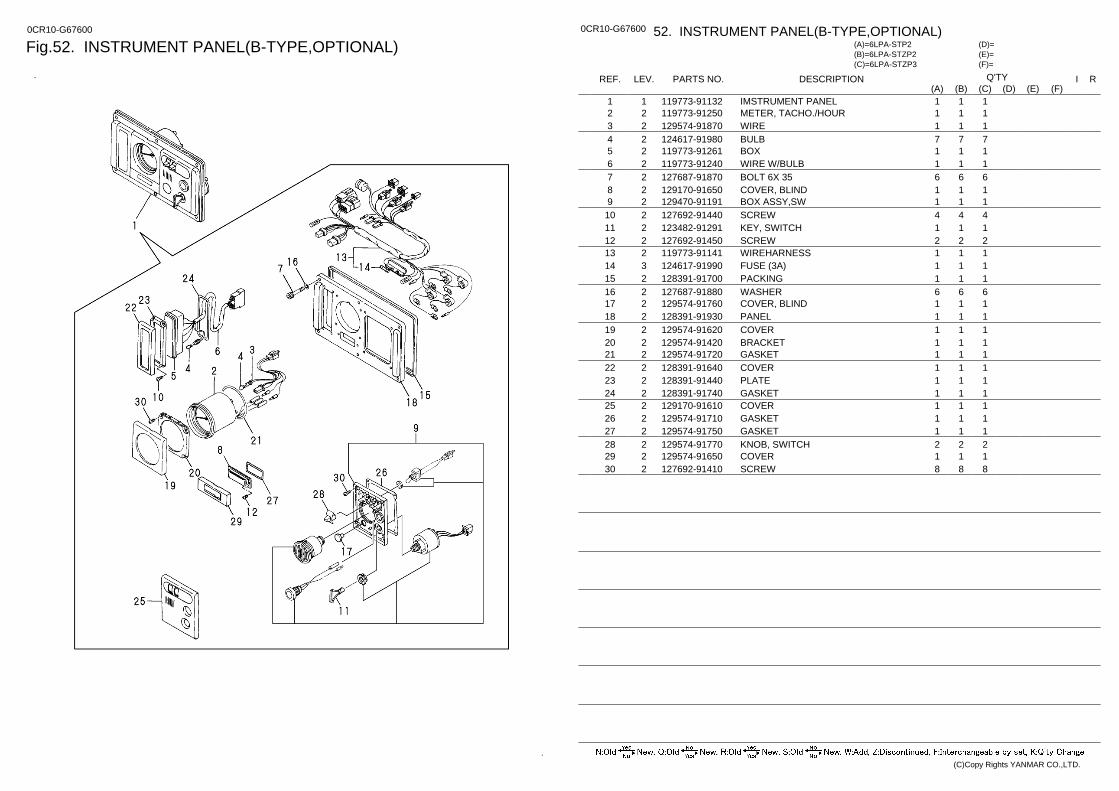
Fig.52. INSTRUMENT PANEL(B-TYPE,OPTIONAL) 0CR10-G67600 0CR10-G67600 52. INSTRUMENT PANEL(B-TYPE,OPTIONAL)
(F)= (E)= (D)=
(C)=6LPA-STZP3 (B)=6LPA-STZP2 (A)=6LPA-STP2
LEV. REF. PARTS NO. DESCRIPTION R I Q'TY (F) (D) (C) (B) (A) (E)
IMSTRUMENT PANEL 119773-91132 1 1 1 1 1 METER, TACHO./HOUR 119773-91250 2 2 1 1 1 WIRE 129574-91870 2 3 1 1 1 BULB 124617-91980 2 4 7 7 7 BOX 119773-91261 2 5 1 1 1 WIRE W/BULB 119773-91240 2 6 1 1 1 BOLT 6X 35 127687-91870 2 7 6 6 6 COVER, BLIND 129170-91650 2 8 1 1 1 BOX ASSY,SW 129470-91191 2 9 1 1 1 SCREW 127692-91440 2 10 4 4 4 KEY, SWITCH 123482-91291 2 11 1 1 1 SCREW 127692-91450 2 12 2 2 2 WIREHARNESS 119773-91141 2 13 1 1 1 FUSE (3A) 124617-91990 3 14 1 1 1 PACKING 128391-91700 2 15 1 1 1 WASHER 127687-91880 2 16 6 6 6 COVER, BLIND 129574-91760 2 17 1 1 1 PANEL 128391-91930 2 18 1 1 1 COVER 129574-91620 2 19 1 1 1 BRACKET 129574-91420 2 20 1 1 1 GASKET 129574-91720 2 21 1 1 1 COVER 128391-91640 2 22 1 1 1 PLATE 128391-91440 2 23 1 1 1 GASKET 128391-91740 2 24 1 1 1 COVER 129170-91610 2 25 1 1 1 GASKET 129574-91710 2 26 1 1 1 GASKET 129574-91750 2 27 1 1 1 KNOB, SWITCH 129574-91770 2 28 2 2 2 COVER 129574-91650 2 29 1 1 1 SCREW 127692-91410 2 30 8 8 8
(C)Copy Rights YANMAR CO.,LTD.
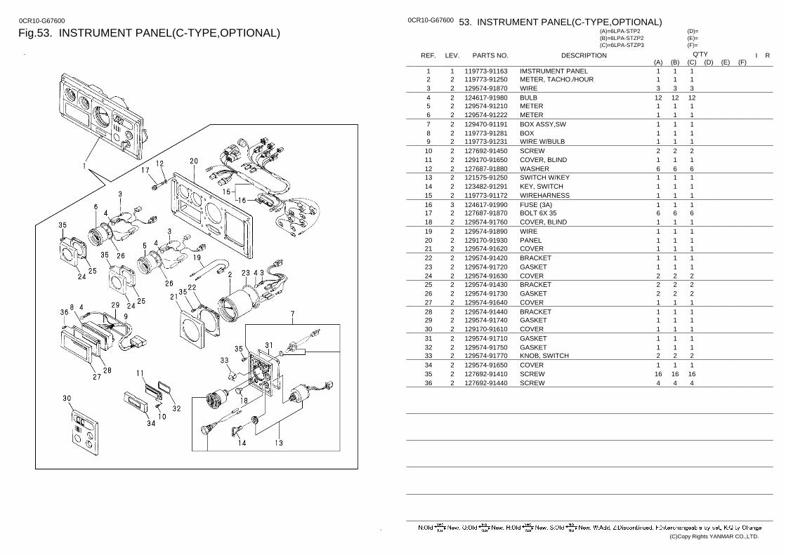
Fig.53. INSTRUMENT PANEL(C-TYPE,OPTIONAL) 0CR10-G67600 0CR10-G67600 53. INSTRUMENT PANEL(C-TYPE,OPTIONAL)
(F)= (E)= (D)=
(C)=6LPA-STZP3 (B)=6LPA-STZP2 (A)=6LPA-STP2
LEV. REF. PARTS NO. DESCRIPTION R I Q'TY (F) (D) (C) (B) (A) (E)
IMSTRUMENT PANEL 119773-91163 1 1 1 1 1 METER, TACHO./HOUR 119773-91250 2 2 1 1 1 WIRE 129574-91870 2 3 3 3 3 BULB 124617-91980 2 4 12 12 12 METER 129574-91210 2 5 1 1 1 METER 129574-91222 2 6 1 1 1 BOX ASSY,SW 129470-91191 2 7 1 1 1 BOX 119773-91281 2 8 1 1 1 WIRE W/BULB 119773-91231 2 9 1 1 1 SCREW 127692-91450 2 10 2 2 2 COVER, BLIND 129170-91650 2 11 1 1 1 WASHER 127687-91880 2 12 6 6 6 SWITCH W/KEY 121575-91250 2 13 1 1 1 KEY, SWITCH 123482-91291 2 14 1 1 1 WIREHARNESS 119773-91172 2 15 1 1 1 FUSE (3A) 124617-91990 3 16 1 1 1 BOLT 6X 35 127687-91870 2 17 6 6 6 COVER, BLIND 129574-91760 2 18 1 1 1 WIRE 129574-91890 2 19 1 1 1 PANEL 129170-91930 2 20 1 1 1 COVER 129574-91620 2 21 1 1 1 BRACKET 129574-91420 2 22 1 1 1 GASKET 129574-91720 2 23 1 1 1 COVER 129574-91630 2 24 2 2 2 BRACKET 129574-91430 2 25 2 2 2 GASKET 129574-91730 2 26 2 2 2 COVER 129574-91640 2 27 1 1 1 BRACKET 129574-91440 2 28 1 1 1 GASKET 129574-91740 2 29 1 1 1 COVER 129170-91610 2 30 1 1 1 GASKET 129574-91710 2 31 1 1 1 GASKET 129574-91750 2 32 1 1 1 KNOB, SWITCH 129574-91770 2 33 2 2 2 COVER 129574-91650 2 34 1 1 1 SCREW 127692-91410 2 35 16 16 16 SCREW 127692-91440 2 36 4 4 4
(C)Copy Rights YANMAR CO.,LTD.
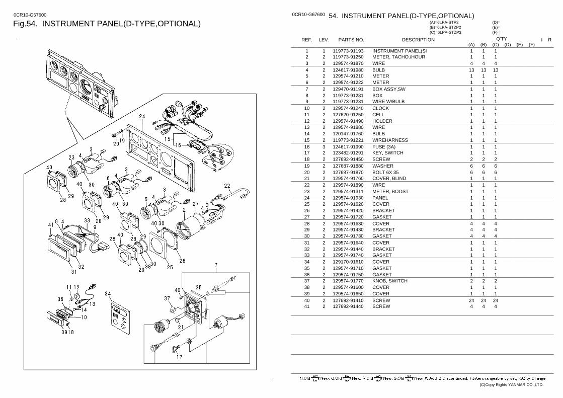
Fig.54. INSTRUMENT PANEL(D-TYPE,OPTIONAL) 0CR10-G67600 0CR10-G67600 54. INSTRUMENT PANEL(D-TYPE,OPTIONAL)
(F)= (E)= (D)=
(C)=6LPA-STZP3 (B)=6LPA-STZP2 (A)=6LPA-STP2
LEV. REF. PARTS NO. DESCRIPTION R I Q'TY (F) (D) (C) (B) (A) (E)
INSTRUMENT PANEL(SI 119773-91193 1 1 1 1 1 METER, TACHO./HOUR 119773-91250 2 2 1 1 1 WIRE 129574-91870 2 3 4 4 4 BULB 124617-91980 2 4 13 13 13 METER 129574-91210 2 5 1 1 1 METER 129574-91222 2 6 1 1 1 BOX ASSY,SW 129470-91191 2 7 1 1 1 BOX 119773-91281 2 8 1 1 1 WIRE W/BULB 119773-91231 2 9 1 1 1 CLOCK 129574-91240 2 10 1 1 1 CELL 127620-91250 2 11 1 1 1 HOLDER 129574-91490 2 12 1 1 1 WIRE 129574-91880 2 13 1 1 1 BULB 120147-91760 2 14 1 1 1 WIREHARNESS 119773-91221 2 15 1 1 1 FUSE (3A) 124617-91990 3 16 1 1 1 KEY, SWITCH 123482-91291 2 17 1 1 1 SCREW 127692-91450 2 18 2 2 2 WASHER 127687-91880 2 19 6 6 6 BOLT 6X 35 127687-91870 2 20 6 6 6 COVER, BLIND 129574-91760 2 21 1 1 1 WIRE 129574-91890 2 22 1 1 1 METER, BOOST 129574-91311 2 23 1 1 1 PANEL 129574-91930 2 24 1 1 1 COVER 129574-91620 2 25 1 1 1 BRACKET 129574-91420 2 26 1 1 1 GASKET 129574-91720 2 27 1 1 1 COVER 129574-91630 2 28 4 4 4 BRACKET 129574-91430 2 29 4 4 4 GASKET 129574-91730 2 30 4 4 4 COVER 129574-91640 2 31 1 1 1 BRACKET 129574-91440 2 32 1 1 1 GASKET 129574-91740 2 33 1 1 1 COVER 129170-91610 2 34 1 1 1 GASKET 129574-91710 2 35 1 1 1 GASKET 129574-91750 2 36 1 1 1 KNOB, SWITCH 129574-91770 2 37 2 2 2 COVER 129574-91600 2 38 1 1 1 COVER 129574-91650 2 39 1 1 1 SCREW 127692-91410 2 40 24 24 24 SCREW 127692-91440 2 41 4 4 4
(C)Copy Rights YANMAR CO.,LTD.
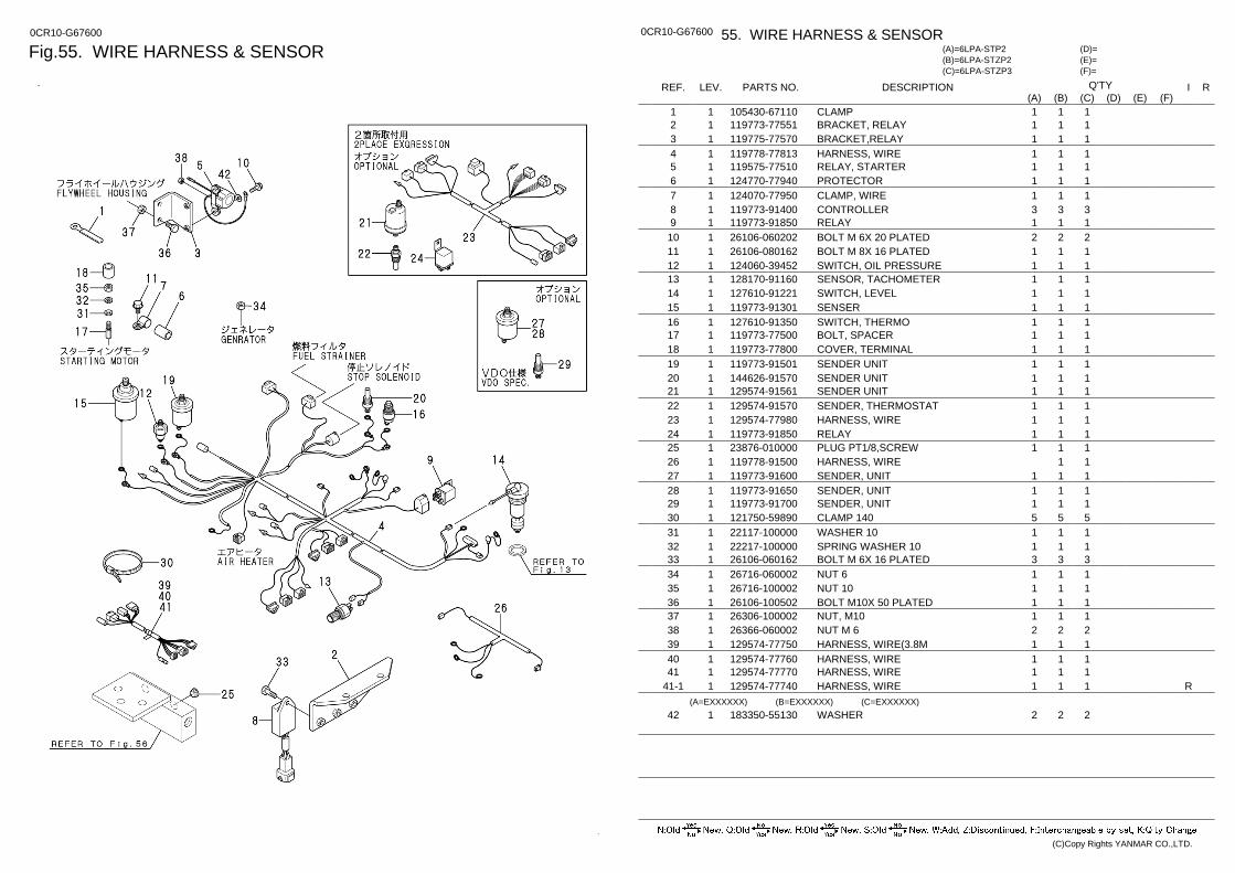
Fig.55. WIRE HARNESS & SENSOR 0CR10-G67600 0CR10-G67600 55. WIRE HARNESS & SENSOR
(F)= (E)= (D)=
(C)=6LPA-STZP3 (B)=6LPA-STZP2 (A)=6LPA-STP2
LEV. REF. PARTS NO. DESCRIPTION R I Q'TY (F) (D) (C) (B) (A) (E)
CLAMP 105430-67110 1 1 1 1 1 BRACKET, RELAY 119773-77551 1 2 1 1 1 BRACKET,RELAY 119775-77570 1 3 1 1 1 HARNESS, WIRE 119778-77813 1 4 1 1 1 RELAY, STARTER 119575-77510 1 5 1 1 1 PROTECTOR 124770-77940 1 6 1 1 1 CLAMP, WIRE 124070-77950 1 7 1 1 1 CONTROLLER 119773-91400 1 8 3 3 3 RELAY 119773-91850 1 9 1 1 1 BOLT M 6X 20 PLATED 26106-060202 1 10 2 2 2 BOLT M 8X 16 PLATED 26106-080162 1 11 1 1 1 SWITCH, OIL PRESSURE 124060-39452 1 12 1 1 1 SENSOR, TACHOMETER 128170-91160 1 13 1 1 1 SWITCH, LEVEL 127610-91221 1 14 1 1 1 SENSER 119773-91301 1 15 1 1 1 SWITCH, THERMO 127610-91350 1 16 1 1 1 BOLT, SPACER 119773-77500 1 17 1 1 1 COVER, TERMINAL 119773-77800 1 18 1 1 1 SENDER UNIT 119773-91501 1 19 1 1 1 SENDER UNIT 144626-91570 1 20 1 1 1 SENDER UNIT 129574-91561 1 21 1 1 1 SENDER, THERMOSTAT 129574-91570 1 22 1 1 1 HARNESS, WIRE 129574-77980 1 23 1 1 1 RELAY 119773-91850 1 24 1 1 1 PLUG PT1/8,SCREW 23876-010000 1 25 1 1 1 HARNESS, WIRE 119778-91500 1 26 1 1 SENDER, UNIT 119773-91600 1 27 1 1 1 SENDER, UNIT 119773-91650 1 28 1 1 1 SENDER, UNIT 119773-91700 1 29 1 1 1 CLAMP 140 121750-59890 1 30 5 5 5 WASHER 10 22117-100000 1 31 1 1 1 SPRING WASHER 10 22217-100000 1 32 1 1 1 BOLT M 6X 16 PLATED 26106-060162 1 33 3 3 3 NUT 6 26716-060002 1 34 1 1 1 NUT 10 26716-100002 1 35 1 1 1 BOLT M10X 50 PLATED 26106-100502 1 36 1 1 1 NUT, M10 26306-100002 1 37 1 1 1 NUT M 6 26366-060002 1 38 2 2 2 HARNESS, WIRE(3.8M 129574-77750 1 39 1 1 1 HARNESS, WIRE 129574-77760 1 40 1 1 1 HARNESS, WIRE 129574-77770 1 41 1 1 1 HARNESS, WIRE 129574-77740 1 41-1 R 1 1 1
(A=EXXXXXX) (B=EXXXXXX) (C=EXXXXXX) WASHER 183350-55130 1 42 2 2 2
(C)Copy Rights YANMAR CO.,LTD.
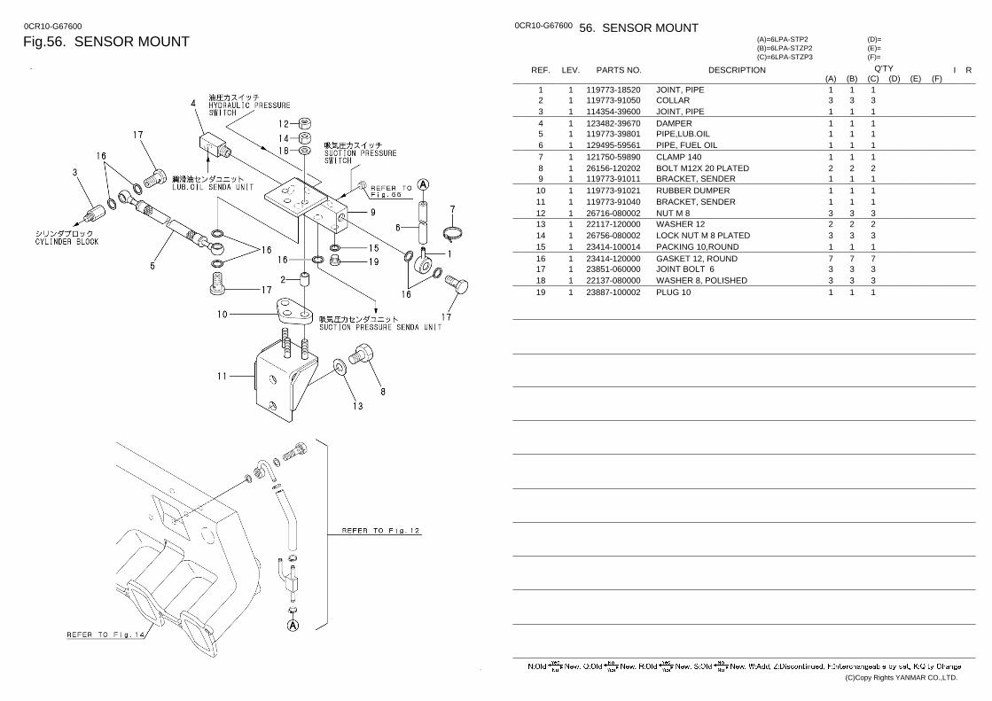
Fig.56. SENSOR MOUNT 0CR10-G67600 0CR10-G67600 56. SENSOR MOUNT
(F)= (E)= (D)=
(C)=6LPA-STZP3 (B)=6LPA-STZP2 (A)=6LPA-STP2
LEV. REF. PARTS NO. DESCRIPTION R I Q'TY (F) (D) (C) (B) (A) (E)
JOINT, PIPE 119773-18520 1 1 1 1 1 COLLAR 119773-91050 1 2 3 3 3 JOINT, PIPE 114354-39600 1 3 1 1 1 DAMPER 123482-39670 1 4 1 1 1 PIPE,LUB.OIL 119773-39801 1 5 1 1 1 PIPE, FUEL OIL 129495-59561 1 6 1 1 1 CLAMP 140 121750-59890 1 7 1 1 1 BOLT M12X 20 PLATED 26156-120202 1 8 2 2 2 BRACKET, SENDER 119773-91011 1 9 1 1 1 RUBBER DUMPER 119773-91021 1 10 1 1 1 BRACKET, SENDER 119773-91040 1 11 1 1 1 NUT M 8 26716-080002 1 12 3 3 3 WASHER 12 22117-120000 1 13 2 2 2 LOCK NUT M 8 PLATED 26756-080002 1 14 3 3 3 PACKING 10,ROUND 23414-100014 1 15 1 1 1 GASKET 12, ROUND 23414-120000 1 16 7 7 7 JOINT BOLT 6 23851-060000 1 17 3 3 3 WASHER 8, POLISHED 22137-080000 1 18 3 3 3 PLUG 10 23887-100002 1 19 1 1 1
(C)Copy Rights YANMAR CO.,LTD.
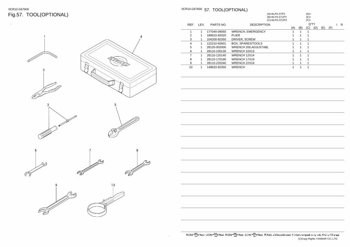
Fig.57. TOOL(OPTIONAL) 0CR10-G67600 0CR10-G67600 57. TOOL(OPTIONAL)
(F)= (E)= (D)=
(C)=6LPA-STZP3 (B)=6LPA-STZP2 (A)=6LPA-STP2
LEV. REF. PARTS NO. DESCRIPTION R I Q'TY (F) (D) (C) (B) (A) (E)
WRENCH, EMERGENCY 177040-09050 1 1 1 1 1 PLIER 189010-92020 1 2 1 1 1 DRIVER, SCREW 104200-92350 1 3 1 1 1 BOX, SPARES/TOOLS 122210-92601 1 4 1 1 1 WRENCH 200,ADJUSTABL 28120-002000 1 5 1 1 1 WRENCH 10X13 28110-100130 1 6 1 1 1 WRENCH 12X14 28110-120140 1 7 1 1 1 WRENCH 17X19 28110-170190 1 8 1 1 1 WRENCH 22X24 28110-220240 1 9 1 1 1 WRENCH 148633-92350 1 10 1 1 1
(C)Copy Rights YANMAR CO.,LTD.
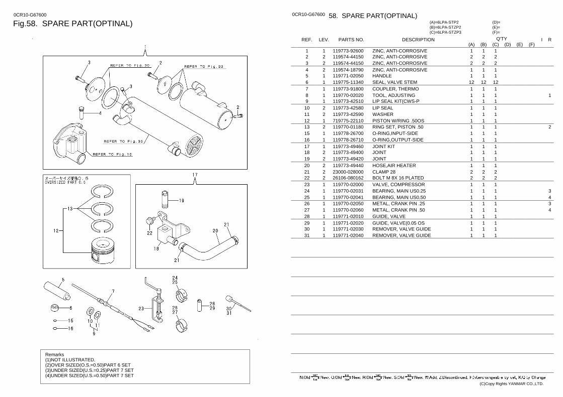
Fig.58. SPARE PART(OPTINAL) 0CR10-G67600
Remarks (1)NOT ILLUSTRATED. (2)OVER SIZED(O.S.=0.50)PART 6 SET (3)UNDER SIZED(U.S.=0.25)PART 7 SET (4)UNDER SIZED(U.S.=0.50)PART 7 SET
0CR10-G67600 58. SPARE PART(OPTINAL)
(F)= (E)= (D)=
(C)=6LPA-STZP3 (B)=6LPA-STZP2 (A)=6LPA-STP2
LEV. REF. PARTS NO. DESCRIPTION R I Q'TY (F) (D) (C) (B) (A) (E)
ZINC, ANTI-CORROSIVE 119773-92600 1 1 1 1 1 ZINC, ANTI-CORROSIVE 119574-44150 2 2 2 2 2 ZINC, ANTI-CORROSIVE 119574-44150 2 3 2 2 2 ZINC, ANTI-CORROSIVE 119574-18790 2 4 1 1 1 HANDLE 119771-02050 1 5 1 1 1 SEAL, VALVE STEM 119775-11340 1 6 12 12 12 COUPLER, THERMO 119773-91800 1 7 1 1 1
1 TOOL, ADJUSTING 119770-02020 1 8 1 1 1 LIP SEAL KIT(CWS-P 119773-42510 1 9 1 1 1 LIP SEAL 119773-42580 2 10 1 1 1 WASHER 119773-42590 2 11 1 1 1 PISTON W/RING .50OS 719775-22110 1 12 1 1 1
2 RING SET, PISTON .50 119770-01180 2 13 1 1 1 O-RING,INPUT-SIDE 119778-26700 1 15 1 1 1 O-RING,OUTPUT-SIDE 119778-26710 1 16 1 1 1 JOINT KIT 119773-49460 1 17 1 1 1 JOINT 119773-49400 2 18 1 1 1 JOINT 119773-49420 2 19 1 1 1 HOSE,AIR HEATER 119773-49440 2 20 1 1 1 CLAMP 28 23000-028000 2 21 2 2 2 BOLT M 8X 16 PLATED 26106-080162 2 22 2 2 2 VALVE, COMPRESSOR 119770-02000 1 23 1 1 1
3 BEARING, MAIN US0.25 119770-02031 1 24 1 1 1 4 BEARING, MAIN US0.50 119770-02041 1 25 1 1 1 3 METAL, CRANK PIN .25 119770-02050 1 26 1 1 1 4 METAL, CRANK PIN .50 119770-02060 1 27 1 1 1
GUIDE, VALVE 119771-02010 1 28 1 1 1 GUIDE, VALVE(0.05 OS 119771-02020 1 29 1 1 1 REMOVER, VALVE GUIDE 119771-02030 1 30 1 1 1 REMOVER, VALVE GUIDE 119771-02040 1 31 1 1 1
(C)Copy Rights YANMAR CO.,LTD.
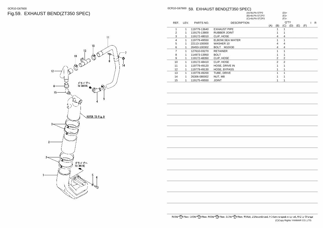
Fig.59. EXHAUST BEND(ZT350 SPEC) 0CR10-G67600 0CR10-G67600 59. EXHAUST BEND(ZT350 SPEC)
(F)= (E)= (D)=
(C)=6LPA-STZP3 (B)=6LPA-STZP2 (A)=6LPA-STP2
LEV. REF. PARTS NO. DESCRIPTION R I Q'TY (F) (D) (C) (B) (A) (E)
EXHAUST PIPE 119779-13640 1 1 1 1 RUBBER JOINT 119175-13800 1 2 1 1 CLIP, HOSE 119172-48010 1 3 4 4 ELBOW,SEA WATER 119779-49550 1 4 1 1 WASHER 10 22113-100000 1 5 4 4 BOLT M10X30 26453-100302 1 6 4 4 RETAINER 127610-03270 1 7 1 1 BOLT 114973-13950 1 8 1 1 CLIP, HOSE 119172-48350 1 9 2 2 CLIP, HOSE 119172-48410 1 10 2 2 HOSE, DRIVE IN 119779-49120 1 11 1 1 HOSE, BYPASS 119779-49130 1 12 1 1 TUBE, DRIVE 119778-49200 1 13 1 1 NUT, M8 26306-080002 1 14 1 1 JOINT 119175-49550 1 15 1 1
(C)Copy Rights YANMAR CO.,LTD.
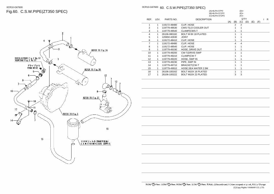
Fig.60. C.S.W.PIPE(ZT350 SPEC) 0CR10-G67600 0CR10-G67600 60. C.S.W.PIPE(ZT350 SPEC)
(F)= (E)= (D)=
(C)=6LPA-STZP3 (B)=6LPA-STZP2 (A)=6LPA-STP2
LEV. REF. PARTS NO. DESCRIPTION R I Q'TY (F) (D) (C) (B) (A) (E)
CLIP, HOSE 119172-48480 1 1 2 2 CWS-T(LO COOLER OUT 119779-49530 1 2 1 1 CLAMP(CWS-T 119779-49540 1 3 1 1 BOLT M 8X 18 PLATED 26106-080182 1 4 1 1 JOINT 120650-42630 1 5 1 1 CLIP, HOSE 119172-48410 1 6 1 1 CLIP, HOSE 119172-48480 1 7 4 4 CLIP, HOSE 119172-48540 1 8 1 1 HOSE, DRIVE OUT 119779-49190 1 9 1 1 CW-T(DRIVE-SWP 119779-49200 1 10 1 1 CLAMP(CW-T 119779-49210 1 11 1 1 HOSE, SWP IN 119779-49220 1 12 1 1 PIPE, SWP IN 119779-49230 1 13 1 1 BRACKET(CW-T 119779-49710 1 14 1 1 HOSE,SEA WATER 2.5M 119779-49910 1 15 1 1 BOLT M10X 16 PLATED 26106-100162 1 16 1 1 BOLT M10X 22 PLATED 26106-100222 1 17 3 3
(C)Copy Rights YANMAR CO.,LTD.
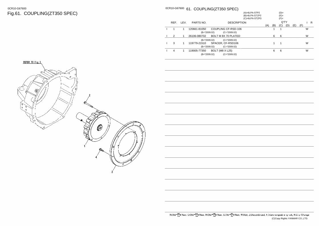
Fig.61. COUPLING(ZT350 SPEC) 0CR10-G67600 0CR10-G67600 61. COUPLING(ZT350 SPEC)
(F)= (E)= (D)=
(C)=6LPA-STZP3 (B)=6LPA-STZP2 (A)=6LPA-STP2
LEV. REF. PARTS NO. DESCRIPTION R I Q'TY (F) (D) (C) (B) (A) (E)
COUPLING CF-RSD-106 120661-81050 1 1 W 1 1 I (B=*2009.02) (C=*2009.02)
BOLT M 8X 70 PLATED 26106-080702 1 2 W 6 6 I (B=*2009.02) (C=*2009.02)
SPACER, CF-RSD106 119779-21510 1 3 W 1 1 I (B=*2009.02) (C=*2009.02)
BOLT (M8 X L25) 119005-77350 1 4 W 6 6 I (B=*2009.02) (C=*2009.02)
(C)Copy Rights YANMAR CO.,LTD.
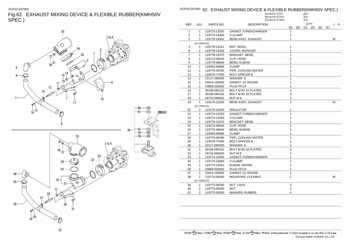
Fig.62. EXHAUST MIXING DEVICE & FLEXIBLE RUBBER(KMH50V SPEC.)
0CR10-G67600 0CR10-G67600 62. EXHAUST MIXING DEVICE & FLEXIBLE RUBBER(KMH50V SPEC.)
(F)= (E)= (D)=
(C)=6LPA-STZP3 (B)=6LPA-STZP2 (A)=6LPA-STP2
LEV. REF. PARTS NO. DESCRIPTION R I Q'TY (F) (D) (C) (B) (A) (E)
GASKET,TURBOCHARGER 119773-13250 1 1 1 V-CLAMP 119773-13300 1 2 1 BEND ASSY, EXHAUST 119778-13301 1 3 W 1
(A=*2009.01) MAT, WOOL 119778-13311 2 4 1 COVER, MUFFLER 119778-13330 1 6 1 BRACKET, BEND 119778-13370 1 7 1 CLIP, HOSE 119172-48540 1 8 2 BEND, ELBOW 119775-48640 1 9 1 CLAMP 119593-49080 1 10 1 PIPE, COOLING WATER 119775-49780 1 11 1 BOLT,SPACER B 119578-77450 1 12 1 WASHER 8 22117-080000 1 13 1 GASKET 13, ROUND 23414-130000 1 14 1 PLUG PF1/4 23893-020002 1 15 1 BOLT M 8X 12 PLATED 26106-080122 1 16 4 BOLT M 8X 16 PLATED 26106-080162 1 17 3 NUT M 8 26716-080002 1 18 1 BEND ASSY, EXHAUST 119175-13200 1 19 W 1
(A=*2009.01) INSULATOR 119175-13220 2 21 1 GASKET,TURBOCHARGER 119773-13250 1 22 1 V-CLAMP 119773-13300 1 23 1 BRACKET, BEND 119778-13370 1 24 1 CLIP, HOSE 119172-48540 1 25 2 BEND, ELBOW 119775-48640 1 26 1 CLAMP 119593-49080 1 27 1 PIPE, COOLING WATER 119775-49780 1 28 1 BOLT,SPACER B 119578-77450 1 29 1 WASHER 8 22117-080000 1 30 1 BOLT M 8X 16 PLATED 26106-080162 1 31 3 NUT M 8 26716-080002 1 32 1 GASKET,TURBOCHARGER 119773-13250 1 33 1 V-CLAMP 119773-13300 1 34 1 ELBOW, MIXING 119773-13501 1 35 1 PLUG PF1/4 23893-020002 1 36 1 GASKET 13, ROUND 23414-130000 1 37 1 MOUNTING, FLEXIBLE 119773-08300 1 38 W 2
(A=*2009.01)
NUT, LOCK 119773-08330 2 39 4 NUT 119773-08340 2 40 2 WASHER, RUBBER 119773-08350 2 41 4
(C)Copy Rights YANMAR CO.,LTD.
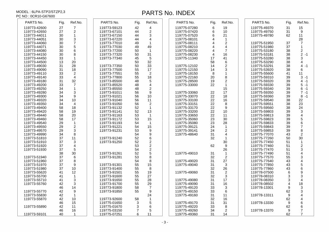
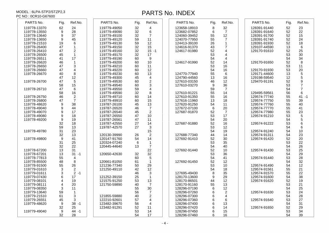
Part Number Index
All parts are stipulated in the order of part numbers. (Depending on the area in which the part is used.) This index will display the location of the part according to each part number.
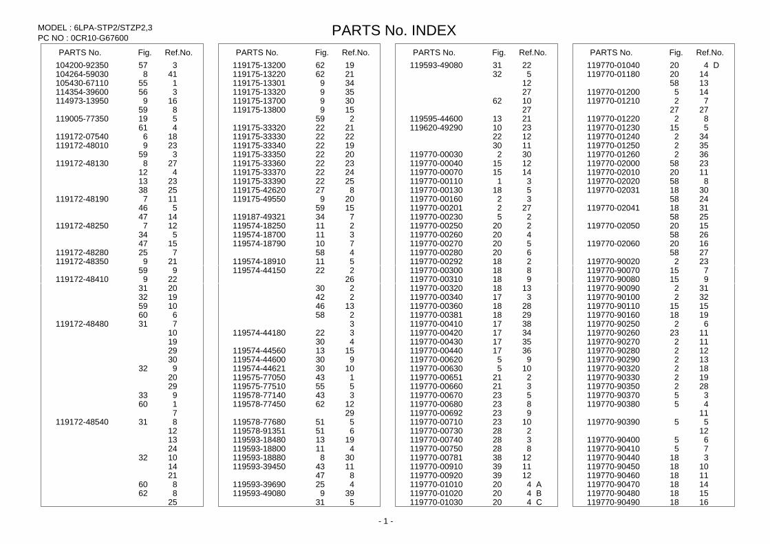
PC NO : 0CR10-G67600 PARTS No. INDEX MODEL : 6LPA-STP2/STZP2,3
PARTS No. Fig. Ref.No. PARTS No. Fig. Ref.No. PARTS No. Fig. Ref.No. PARTS No. Fig. Ref.No. 104200-92350 357 119175-13200 1962 119593-49080 2231 D119770-01040 420 104264-59030 418 119175-13220 2162 532 119770-01180 1420 105430-67110 155 119175-13301 349 12 1358 114354-39600 356 119175-13320 359 27 119770-01200 145 114973-13950 169 119175-13700 309 1062 119770-01210 72
859 119175-13800 159 27 2727 119005-77350 519 259 119595-44600 2113 119770-01220 82
461 119175-33320 2122 119620-49290 2310 119770-01230 515 119172-07540 186 119175-33330 2222 1222 119770-01240 342 119172-48010 239 119175-33340 1922 1130 119770-01250 352
359 119175-33350 2022 119770-00030 302 119770-01260 362 119172-48130 278 119175-33360 2322 119770-00040 1215 119770-02000 2358
412 119175-33370 2422 119770-00070 1415 119770-02010 1120 2313 119175-33390 2522 119770-00110 31 119770-02020 858 2538 119175-42620 827 119770-00130 518 119770-02031 3018
119172-48190 117 119175-49550 209 119770-00160 32 2458 546 1559 119770-00201 272 119770-02041 3118
1447 119187-49321 734 119770-00230 25 2558 119172-48250 127 119574-18250 211 119770-00250 220 119770-02050 1520
534 119574-18700 311 119770-00260 420 2658 1547 119574-18790 710 119770-00270 520 119770-02060 1620
119172-48280 725 458 119770-00280 620 2758 119172-48350 219 119574-18910 511 119770-00292 218 119770-90020 232
959 119574-44150 222 119770-00300 818 119770-90070 715 119172-48410 229 26 119770-00310 918 119770-90080 915
2031 230 119770-00320 1318 119770-90090 312 1932 242 119770-00340 317 119770-90100 322 1059 1346 119770-00360 2818 119770-90110 1515 660 258 119770-00381 2918 119770-90160 1918
119172-48480 731 3 119770-00410 3817 119770-90250 62 10 119574-44180 322 119770-00420 3417 119770-90260 1123 19 430 119770-00430 3517 119770-90270 112 29 119574-44560 1513 119770-00440 3617 119770-90280 122 30 119574-44600 930 119770-00620 95 119770-90290 132 932 119574-44621 1030 119770-00630 105 119770-90320 182
20 119575-77050 143 119770-00651 221 119770-90330 192 29 119575-77510 555 119770-00660 321 119770-90350 282 933 119578-77140 343 119770-00670 523 119770-90370 35 160 119578-77450 1262 119770-00680 823 119770-90380 45 7 29 119770-00692 923 11
119172-48540 831 119578-77680 551 119770-00710 1023 119770-90390 55 12 119578-91351 651 119770-00730 228 12 13 119593-18480 1913 119770-00740 328 119770-90400 65 24 119593-18800 411 119770-00750 828 119770-90410 75 1032 119593-18880 308 119770-00781 1238 119770-90440 318 14 119593-39450 1143 119770-00910 1139 119770-90450 1018 21 847 119770-00920 1239 119770-90460 1118 860 119593-39690 425 A119770-01010 420 119770-90470 1418 862 119593-49080 399 B119770-01020 420 119770-90480 1518
25 531 C119770-01030 420 119770-90490 1618
- 1 -
PC NO : 0CR10-G67600 PARTS No. INDEX MODEL : 6LPA-STP2/STZP2,3
PARTS No. Fig. Ref.No. PARTS No. Fig. Ref.No. PARTS No. Fig. Ref.No. PARTS No. Fig. Ref.No. 119770-90500 1718 119771-00170 2717 119771-90240 2417 119773-13300 279 119770-90510 417 119771-00190 2917 119771-90250 2517 262 119770-90520 2018 119771-00201 3017 119771-90260 1323 23 119770-90530 2118 119771-00211 817 119771-90290 1338 34 119770-90540 2218 119771-00221 917 119771-90300 1438 119773-13501 129 119770-90550 2318 119771-00230 1017 119771-90310 1538 3562 119770-90560 3717 119771-00240 1317 119771-90320 1638 119773-18100 110 119770-90611 135 119771-00250 1717 119771-90330 1738 119773-18121 2210 119770-90620 223 119771-00261 1817 119771-90340 1339 119773-18160 1110 119770-90630 714 119771-00271 1917 119771-90350 1020 119773-18181 1210
421 119771-00280 2017 119773-01580 392 119773-18210 111 1523 119771-00290 2117 119773-01590 202 119773-18250 288 428 119771-00320 61 119773-01600 13 119773-18320 510
119770-90650 1623 119771-00330 81 119773-03011 17 119773-18330 410 119770-90660 1723 119771-00340 2138 119773-03021 27 119773-18340 310 119770-90670 1823 119771-00351 838 119773-03031 37 119773-18350 610
1938 119771-00360 938 119773-03190 67 119773-18360 1010 119770-90680 1923 119771-00370 1038 119773-03200 77 119773-18410 1410 119770-90690 2023 119771-00390 1039 119773-03251 97 119773-18520 156 119770-90700 2123 119771-00401 1015 119773-03271 107 119773-18530 112 119770-90710 2223 A119771-00411 1015 119773-03301 87 119773-18540 212 119770-90720 2323 B119771-00421 1015 119773-07210 316 119773-18560 312 119770-90730 2423 119771-00430 2817 119773-07280 36 119773-18701 258 119770-90740 514 119771-00440 216 119773-07350 56 119773-18730 268
2523 119771-00450 217 119773-08200 34 119773-18850 298 119770-90750 2623 119771-01270 372 119773-08250 148 119773-21510 419 119770-90800 528 119771-02010 1915 119773-08300 84 119773-28010 119 119770-90810 628 2858 3862 119773-28600 319 119770-90860 614 119771-02020 2015 119773-08310 124 119773-33050 722 119770-90890 1637 2958 119773-08330 94 119773-33060 622 119770-90900 1737 119771-02030 3058 13 119773-33070 422 119770-90930 2038 119771-02040 3158 3962 119773-33080 522
842 119771-02050 558 119773-08340 104 119773-34400 285 119770-90960 1439 119771-10040 11 14 119773-34600 235 119770-90990 41 119771-90050 415 4062 119773-34621 245 119770-91020 155 119771-90060 315 119773-08350 114 119773-34770 255 119770-91040 3917 119771-90070 815 15 119773-34810 165 119770-91050 928 119771-90080 1615 4162 119773-34821 225 119771-00012 215 119771-90110 42 119773-13010 1013 119773-34950 275 119771-00031 1815 119771-90120 52 119773-13100 113 119773-39610 225 119771-00041 1315 24 119773-13160 313 119773-39671 325 119771-00051 617 119771-90130 152 119773-13200 413 119773-39801 556 119771-00060 22 119771-90140 102 119773-13250 19 119773-39820 525 119771-00071 142 119771-90160 252 10 119773-42500 127 119771-00081 172 119771-90170 3117 25 119773-42510 958 119771-00101 222 119771-90180 3217 162 119773-42520 2127 119771-00131 2418 119771-90190 1117 22 119773-42550 427 119771-00141 2518 119771-90200 1417 33 119773-42570 627 119771-00151 2618 119771-90210 1517 119773-13300 29 119773-42580 1058 119771-00160 2718 119771-90230 2317 11 119773-42590 1158
- 2 -
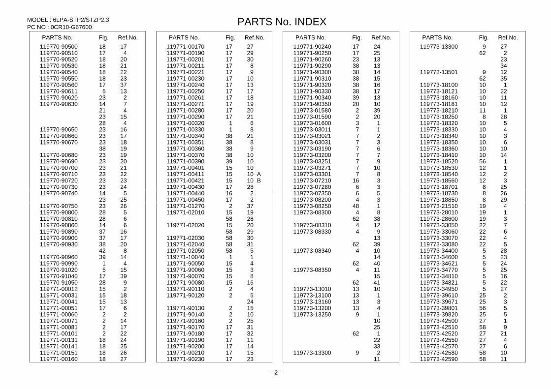
PC NO : 0CR10-G67600 PARTS No. INDEX MODEL : 6LPA-STP2/STZP2,3
PARTS No. Fig. Ref.No. PARTS No. Fig. Ref.No. PARTS No. Fig. Ref.No. PARTS No. Fig. Ref.No. 119773-42600 727 119773-59123 442 119775-07280 196 119775-49370 1531 119773-42650 227 119773-67101 244 119775-07420 106 119775-49750 931 119773-44011 130 119773-67150 344 119775-07520 216 119775-49780 1162 119773-44051 330 119773-67220 444 119775-08101 14 28 119773-44060 730 119773-77010 149 119775-08111 24 119775-51950 737 119773-44071 530 119773-77030 4949 119775-08210 44 119775-51980 137 119773-44080 630 119773-77200 150 119775-08220 74 119775-53180 238 119773-44150 830 119773-77320 3150 119775-08230 164 -1119775-53181 238 119773-44450 133 119773-77340 545 119775-11340 4117 119775-53280 338 119773-44500 2013 3250 658 119775-53290 438 119773-49030 2831 119773-77350 3350 119775-12102 214 -1119775-53291 438 119773-49090 1831 119773-77500 1755 119775-12150 314 119775-53920 638 119773-49110 233 119773-77551 255 119775-18150 18 119775-55600 1141 119773-49140 433 119773-77800 1855 119775-22160 820 -1119775-59310 339 119773-49180 3231 119773-85500 548 119775-28500 219 -1119775-59320 439 119773-49200 733 119773-85520 448 119775-33000 122 -1119775-59330 539 119773-49250 134 119773-85550 248 15 -1119775-59340 639 119773-49280 334 119773-91011 956 119775-33060 1722 -1119775-59350 739 119773-49300 934 119773-91021 1056 119775-33070 1822 -1119775-59360 839 119773-49320 1034 119773-91040 1156 119775-33100 1622 119775-59540 2238 119773-49350 434 119773-91050 256 119775-33151 822 119775-59551 2338 119773-49400 1858 119773-91132 152 119775-33170 922 119775-59560 2438 119773-49420 1958 119773-91141 1352 119775-33200 1022 119775-59803 339 119773-49440 2058 119773-91163 153 119775-33650 1122 119775-59813 439 119773-49460 1758 119773-91172 1553 119775-35060 3023 119775-59823 539 119773-49540 129 119773-91193 154 119775-35080 2823 119775-59833 639 119773-49550 229 119773-91221 1554 119775-39121 124 119775-59843 739 119773-49570 329 119773-91231 953 119775-39141 224 119775-59853 839 119773-49990 834 954 119775-48640 431 119775-77070 243 119773-51810 1137 119773-91240 652 132 119775-77260 3050 119773-51910 337 119773-91250 252 30 119775-77450 151 119773-51920 437 253 962 119775-77460 251 119773-51930 537 254 26 119775-77470 351
3038 119773-91261 552 119775-49010 131 119775-77490 451 119773-51940 637 119773-91281 853 232 119775-77570 355 119773-51960 837 854 119775-49020 2731 119775-77640 443 119773-51970 937 119773-91301 1555 119775-49040 331 119775-77850 543 119773-51980 1037 119773-91400 855 2632 119775-77860 643 119773-55620 1241 119773-91501 1955 119775-49060 231 119778-07500 96 119773-55700 141 119773-91600 2755 332 119778-08310 33 119773-55710 341 119773-91650 2855 119775-49080 1731 119778-08350 43 119773-55760 342 119773-91700 2955 119775-49090 1631 119778-08502 184
1446 119773-91800 758 119775-49120 333 119778-13301 39 119773-55770 942 119773-91850 955 119775-49150 633 362 119773-55830 142 24 119775-49160 1131 119778-13311 49 119773-55870 1042 119773-92600 158 1632 462
1546 119775-01650 53 119775-49170 3131 119778-13330 69 119773-55890 1142 119775-01670 63 119775-49220 833 662
1646 119775-03150 57 119775-49260 234 119778-13370 79 119773-59101 140 119775-07251 116 119775-49360 1431 762
- 3 -
PC NO : 0CR10-G67600 PARTS No. INDEX MODEL : 6LPA-STP2/STZP2,3
PARTS No. Fig. Ref.No. PARTS No. Fig. Ref.No. PARTS No. Fig. Ref.No. PARTS No. Fig. Ref.No. 119778-13370 2462 119779-49050 432 123658-18910 328 128391-91440 2352 119778-13550 289 119779-49090 632 123682-07852 76 128391-91640 2252 119778-13640 379 119779-49100 732 124060-39452 1255 128391-91700 1552 119778-13650 459 119779-49120 1159 124070-77950 755 128391-91740 2452 119778-21510 619 119779-49130 1259 124413-39100 126 128391-91930 1852 119778-26400 147 119779-49150 1532 124616-91370 743 129107-44590 613 119778-26410 247 -1119779-49160 1532 124617-91980 452 129170-91610 2552 119778-26500 145 119779-49170 1732 453 3053 119778-26511 1741 119779-49190 960 454 3454 119778-26620 146 119779-49200 1060 124617-91990 1452 129170-91650 852 119778-26650 347 119779-49210 1160 1653 1153 119778-26660 447 119779-49220 1260 1654 129170-91930 2053 119778-26670 840 119779-49230 1360 124770-77940 655 129171-44600 513
1247 119779-49300 445 124790-44560 1613 129198-59540 512 119778-26700 547 119779-49530 260 127610-03150 1246 129470-91191 952
1558 119779-49540 360 127610-03270 369 753 119778-26710 647 119779-49550 459 759 754
1658 119779-49590 832 127610-91221 1455 129495-59561 656 119778-26750 246 119779-49710 1460 127610-91350 1655 -1129574-77740 4155 119778-26800 747 119779-49910 1560 127616-11960 1813 129574-77750 3955 119778-48620 389 119787-26100 1345 127620-91250 1154 129574-77760 4055 119778-49040 449 119787-26520 746 127672-07100 206 129574-77770 4155 119778-49070 179 119787-26540 245 127687-91870 752 129574-77980 2355 119778-49080 189 119787-26550 1047 1753 129574-91210 553 119778-49200 199 119787-26561 1147 2054 554
1832 119787-42550 1427 127687-91880 1652 129574-91222 653 1359 119787-42570 327 1253 654
119778-49780 2331 15 1954 129574-91240 1054 1332 120130-39990 226 127688-77340 1444 129574-91311 2354
119778-49800 419 120147-91760 1454 127692-91410 3052 129574-91420 2052 2531 120324-07240 16 3553 2253 2232 120445-44640 713 4054 2654
119778-67200 3113 22 127692-91440 1052 129574-91430 2553 -1 119778-67201 3113 120650-42630 3232 3653 2954
119778-77813 455 560 4154 129574-91440 2853 119778-85500 848 120661-81050 161 127692-91450 1252 3254 119778-91500 2655 121236-77340 2950 1053 129574-91490 1254 119779-01610 23 121250-49110 1242 1854 129574-91561 2155
-1 119779-01611 23 346 127695-49430 358 129574-91570 2255 119779-07430 176 121252-39150 125 128170-13600 299 129574-91600 3854 119779-08101 194 121575-91250 1353 128170-86501 1244 129574-91620 1952 119779-08111 204 121750-59890 740 128170-91160 1355 2153 119779-08350 113 3055 128296-07190 126 2554 119779-13640 159 756 128296-07260 26 129574-91630 2453 119779-21510 361 121855-59880 240 128296-07300 46 2854 119779-26551 345 122210-92601 457 128296-07360 66 129574-91640 2753
-1 119779-48620 389 123482-39670 456 128296-07400 136 3154 2532 123482-91291 1152 128296-07420 146 129574-91650 2952
-1 119779-49040 449 1453 128296-07450 156 3453 2832 1754 128296-07460 166 3954
- 4 -
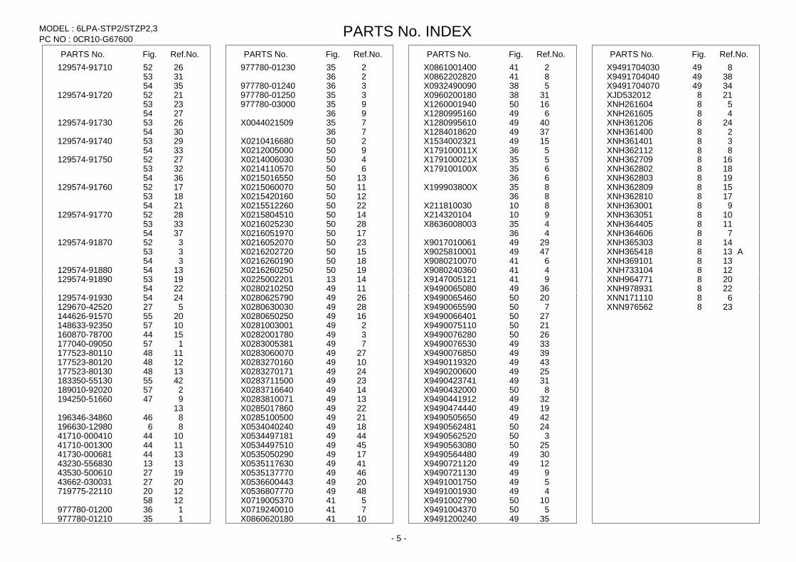
PC NO : 0CR10-G67600 PARTS No. INDEX MODEL : 6LPA-STP2/STZP2,3
PARTS No. Fig. Ref.No. PARTS No. Fig. Ref.No. PARTS No. Fig. Ref.No. PARTS No. Fig. Ref.No. 129574-91710 2652 977780-01230 235 X0861001400 241 X9491704030 849
3153 236 X0862202820 841 X9491704040 3849 3554 977780-01240 336 X0932490090 538 X9491704070 3449
129574-91720 2152 977780-01250 335 X0960200180 3138 XJD532012 218 2353 977780-03000 935 X1260001940 1650 XNH261604 58 2754 936 X1280995160 649 XNH261605 48
129574-91730 2653 X0044021509 735 X1280995610 4049 XNH361206 248 3054 736 X1284018620 3749 XNH361400 28
129574-91740 2953 X0210416680 250 X1534002321 1549 XNH361401 38 3354 X0212005000 950 X179100011X 536 XNH362112 88
129574-91750 2752 X0214006030 450 X179100021X 535 XNH362709 168 3253 X0214110570 650 X179100100X 635 XNH362802 188 3654 X0215016550 1350 636 XNH362803 198
129574-91760 1752 X0215060070 1150 X199903800X 835 XNH362809 158 1853 X0215420160 1250 836 XNH362810 178 2154 X0215512260 2250 X211810030 810 XNH363001 98
129574-91770 2852 X0215804510 1450 X214320104 910 XNH363051 108 3353 X0216025230 2850 X8636008003 435 XNH364405 118 3754 X0216051970 1750 436 XNH364606 78
129574-91870 352 X0216052070 2350 X9017010061 2949 XNH365303 148 353 X0216202720 1550 X9025810001 4749 AXNH365418 138 354 X0216260190 1850 X9080210070 641 XNH369101 138
129574-91880 1354 X0216260250 1950 X9080240360 441 XNH733104 128 129574-91890 1953 X0225002201 1413 X9147005121 941 XNH964771 208
2254 X0280210250 1149 X9490065080 3649 XNH978931 228 129574-91930 2454 X0280625790 2649 X9490065460 2050 XNN171110 68 129670-42520 527 X0280630030 2849 X9490065590 750 XNN976562 238 144626-91570 2055 X0280650250 1649 X9490066401 2750 148633-92350 1057 X0281003001 249 X9490075110 2150 160870-78700 1544 X0282001780 349 X9490076280 2650 177040-09050 157 X0283005381 749 X9490076530 3349 177523-80110 1148 X0283060070 2749 X9490076850 3949 177523-80120 1248 X0283270160 1049 X9490119320 4349 177523-80130 1348 X0283270171 2449 X9490200600 2549 183350-55130 4255 X0283711500 2349 X9490423741 3149 189010-92020 257 X0283716640 1449 X9490432000 850 194250-51660 947 X0283810071 1349 X9490441912 3249
13 X0285017860 2249 X9490474440 1949 196346-34860 846 X0285100500 2149 X9490505650 4249 196630-12980 86 X0534040240 1849 X9490562481 2450 41710-000410 1044 X0534497181 4449 X9490562520 350 41710-001300 1144 X0534497510 4549 X9490563080 2550 41730-000681 1344 X0535050290 1749 X9490564480 3049 43230-556830 1313 X0535117630 4149 X9490721120 1249 43530-500610 1927 X0535137770 4649 X9490721130 949 43662-030031 2027 X0536600443 2049 X9491001750 549 719775-22110 1220 X0536807770 4849 X9491001930 449
1258 X0719005370 541 X9491002790 1050 977780-01200 136 X0719240010 741 X9491004370 550 977780-01210 135 X0860620180 1041 X9491200240 3549
- 5 -