parts manual: lt28 (current)
TRANSCRIPT

Wood-Mizer® SawmillParts Manual
LT28 rev. A6.15
Safety is our #1 concern! Read and understandall safety information and instructions before oper-ating, setting up or maintaining this machine.
Form #1339

©2019
Printed in the United States of America, all rights reserved. No part of this man-ual may be reproduced in any form by any photographic, electronic, mechanicalor other means or used in any information storage and retrieval system withoutwritten permission from
Wood-Mizer 8180 West 10th Street
Indianapolis, Indiana 46214
CaliforniaProposition 65 Warning
WARNING: Breathing gas/diesel engine exhaust exposes you to chemicals known to the State of California to cause cancer and birth defects or other reproductive harm.
Always start and operate the engine in a well-ventilated area.If in an enclosed area, vent the exhaust to the outside.Do not modify or tamper with the exhaust system.Do not idle the engine except as necessary.
For more information go to www.P65warnings.ca.gov.
WARNING: Drilling, sawing, sanding or machining wood products can expose you to wood dust, a substance known to the State of California to cause cancer. Avoid inhaling wood dust or use a dust mask or other safeguards for personal protection.
For more information go to www.P65Warnings.ca.gov/wood.

Table of Contents Section-Page
SECTION 1 GENERAL INFORMATION 1-1
1.1 How To Use The Parts List ....................................................................1-11.2 Sample Assembly ...................................................................................1-1
SECTION 2 BLADE GUIDE ROLLERS & ARM 2-1
2.1 Blade Guide Assembly, Idle Side...........................................................2-12.2 Blade Guide Assembly, Drive Side........................................................2-32.3 Blade Guide Arm....................................................................................2-5
SECTION 3 BLADE WHEELS & TENSIONER 3-7
3.1 Blade Drive Assembly............................................................................3-73.2 Idle Blade Wheel Assembly ...................................................................3-93.3 Blade Tensioner Assembly...................................................................3-11
SECTION 4 SAW HEAD 4-1
4.1 Water Lube Assembly ............................................................................4-14.2 Saw Head Decals....................................................................................4-24.3 Blade Housing Covers............................................................................4-44.4 Sawdust Chute ........................................................................................4-5
SECTION 5 CONTROL & BATTERY BOXES 5-1
5.1 Control Assembly (Optional) .................................................................5-15.2 Battery Box Assembly............................................................................5-3
SECTION 6 UP/DOWN SYSTEM 6-1
6.1 Saw Head Mount ....................................................................................6-16.2 Manual Crank Assembly ........................................................................6-36.3 Up/Down Assist Assembly.....................................................................6-5
SECTION 7 FEED SYSTEM & TRACK ROLLERS 7-1
7.1 Track Rollers And Wipers......................................................................7-17.2 Manual Feed ...........................................................................................7-37.3 Power Feed Assembly (Optional) ..........................................................7-57.4 Feed Chain/Stop .....................................................................................7-6
SECTION 8 BED FRAME ASSEMBLY 8-1
8.1 Bed Rail Assembly, Front And Rear......................................................8-18.2 Bed Rail Assembly, Middle Front..........................................................8-38.3 Bed Rail Assembly, Middle Rear...........................................................8-48.4 Leg Assembly.........................................................................................8-68.5 Pivot Bed Rail Assembly........................................................................8-8
Table of Contents WMdoc032619 iii

Table of Contents Section-Page
8.6 Log Side Support Assembly...................................................................8-98.7 Safety Chain Assembly ........................................................................8-118.8 Bed Frame Decals.................................................................................8-128.9 Log Clamp............................................................................................8-138.10 Log Loading Ramps .............................................................................8-148.11 Board Outfeed Table (Optional)...........................................................8-15
SECTION 9 MISCELLANEOUS 9-1
9.1 Replacement Manuals ............................................................................9-19.2 Tools .......................................................................................................9-2
INDEX I
iv WMdoc032619 Table of Contents

General InformationHow To Use The Parts List
General Information 28doc032619 1-1
1
SECTION 1 GENERAL INFORMATION
1.1 How To Use The Parts List
Use the table of contents or index to locate the assembly that contains the part youneed.
Go to the appropriate section and locate the part in the illustration.
Use the number pointing to the part to locate the correct part number and descrip-tion in the table.
Parts shown indented under another part are included with that part.
Parts marked with a diamond () are only available in the assembly listed above thepart.
See the sample table below. Sample Part #A01111 includes part F02222-2 and subas-sembly A03333. Subassembly A03333 includes part S04444-4 and subassemblyK05555. The diamond () indicates that S04444-4 is not available except in subassemblyA03333. Subassembly K05555 includes parts M06666 and F07777-77. The diamond ()indicates M06666 is not available except in subassembly K05555.
To Order Parts:
From the continental U.S., call 1-800-525-8100 to order parts. Have your customernumber, vehicle identification number, and part numbers ready when you call.
From other international locations, contact the Wood-Mizer distributor in your areafor parts.
1.2 Sample AssemblyREF DESCRIPTION (Indicates Parts Available In Assemblies Only) PART # QTY.
SAMPLE ASSEMBLY, COMPLETE (INCLUDES ALL INDENTED PARTS BELOW) A01111 1
1 Sample Part F02222-22 1
Sample Subassembly (Includes All Indented Parts Below) A03333 1
2 Sample Part ( Indicates Part Is Only Available With A03333) S04444-4 1
Sample Subassembly (Includes All Indented Parts Below) K05555 1
3 Sample Part ( Indicates Part Is Only Available With K05555) M06666 2
4 Sample Part F07777-77 1

Blade Guide Rollers & ArmBlade Guide Assembly, Idle Side2
SECTION 2 BLADE GUIDE ROLLERS & ARM
2.1 Blade Guide Assembly, Idle Side
REF DESCRIPTION ( Indicates Parts Available In Assemblies Only) PART # QTY.
BLADE GUIDE ASSEMBLY, COMPLETE IDLE SIDE A08197 1
1 Nut, 1/2-20 Hex Nylon Lock F05010-15 1
Roller Assembly, Blade Guide (standard) A04925 1
Bearing Kit, Blade Guide Rebuild K07079 1
2 Washer, 5/8" White Felt P04252 1
3 Ring, 1 1/8" Interior Retaining F04254-1 1
4 Bearing, R8-2RS Blade Guide 015975 2
5 Washer, 5/8" Gray Felt P06455 1
1
6
44
3
7
7
5
2
8
9
10
11
10
11
12
1313
13
13
14
14
14
14
15 SM0310C
16
17
18
19
20
21
2223
Optional RelubeBlade Guide Roller
2-1 28doc032619 Blade Guide Rollers & Arm

Blade Guide Rollers & ArmBlade Guide Assembly, Idle Side 2
Screw, 1/4-28 x 1/4” Socket Head Cup Point Set Black Oxide F05005-105 1
Instruction Sheet, Blade Guide Rebuild 057407-1507 1
6 Roller, Flanged Blade Guide S04250 1
Instruction Sheet, Blade Guide Roller Replacement A04925-364 1
7 Spacer, Blade Guide S04253 2
8 Bolt, Blade Guide Roller 036373 1
9 Bracket, Blade Guide Idle Side With Water Tube W08495 1
10 Screw, 3/8-24 X 1 1/4" Stainless Steel Socket Head Flat Point F05007-96 2
11 Nut, 3/8-24 Jam F05010-22 2
12 Shaft, Blade Guide Adjustment S08196 1
13 SCREW, 3/8-24 X 3/4" STAINLESS STEEL SOCKET HEAD FLAT POINT F05007-95 4
14 NUT, 3/8-24 JAM F05010-22 4
15 TUBE, BLADE GUIDE MOUNT (See Section 2.3) W08159 1
ROLLER ASSEMBLY, BLADE GUIDE RELUBE (OPTIONAL) 016568 1
Bearing Kit, Relube Blade Guide Rebuild 057407 1
16 Washer, 5/8" White Felt P04252 1
17 Ring, 1 1/8" Interior Retaining F04254-1 1
18 Bearing, R8-2RS Blade Guide 015975 1 2
19 Washer, 5/8" Gray Felt P06455 1
Instruction Sheet, Blade Guide Rebuild 057407-1507 1
20 Spacer, Blade Guide Bearing 035411 1
21 Roller, Flanged Blade Guide Relube 035426 1
Instruction Sheet, Blade Guide Roller Replacement A04925-364 1
22 BOLT, BLADE GUIDE ROLLER (RELUBE ONLY) S08192 1
23 FITTING, 1/4-28 GREASE (RELUBE ONLY) P05060 1
1 Bearing must be modified for use with relube roller assemblies. Remove one seal from each bearing, place open sides facing eachother and place spacer 035411 between bearings.
Blade Guide Rollers & Arm 28doc032619 2-2

Blade Guide Rollers & ArmBlade Guide Assembly, Drive Side2
2.2 Blade Guide Assembly, Drive Side
REF DESCRIPTION ( Indicates Parts Available In Assemblies Only) PART # QTY.
BLADE GUIDE ASSEMBLY, COMPLETE DRIVE SIDE A08191 1
1 Nut, 1/2-20 Hex Nylon Lock F05010-15 1
Roller Assembly, Blade Guide (standard) A04925 1
Bearing Kit, Blade Guide Rebuild K07079 1
2 Washer, 5/8" White Felt P04252 1
3 Ring, 1 1/8" Interior Retaining F04254-1 1
4 Bearing, R8-2RS Blade Guide 015975 2
5 Washer, 5/8" Gray Felt P06455 1
Screw, 1/4-28 x 1/4” Socket Head Cup Point Set Black Oxide F05005-105 1
Instruction Sheet, Blade Guide Rebuild 057407-1507 1
6 Roller, Flanged Blade Guide S04250 1
Instruction Sheet, Blade Guide Roller Replacement A04925-364 1
7 Spacer, Blade Guide S04253 2
8 Bolt, Blade Guide Roller 036373 1
9 Bracket, Blade Guide Drive Side W08482 1
10 Screw, 3/8-24 X 1 1/4" Stainless Steel Socket Head Flat Point F05007-96 2
11 Nut, 3/8-24 Jam F05010-22 2
12 Shaft, Blade Guide Adjustment S08196 1
13 SCREW, 3/8-24 X 3/4" STAINLESS STEEL SOCKET HEAD FLAT POINT SET F05007-95 3
14 NUT, 3/8-24 JAM F05010-22 4
1
6
4
3
7
7
4
5
2
8
9
10
11
10
11
12
13
14
1314
13
15
14
14
13
150122D
16
17
18
21
19
20
22
23
Optional RelubeBlade Guide Roller
2-3 28doc032619 Blade Guide Rollers & Arm
Blade Guide Rollers & ArmBlade Guide Assembly, Drive Side 2
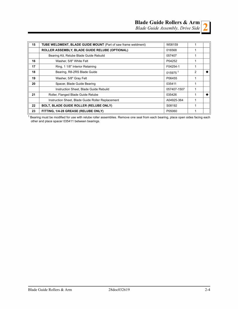
15 TUBE WELDMENT, BLADE GUIDE MOUNT (Part of saw frame weldment) W08159 1
ROLLER ASSEMBLY, BLADE GUIDE RELUBE (OPTIONAL) 016568 1
Bearing Kit, Relube Blade Guide Rebuild 057407 1
16 Washer, 5/8" White Felt P04252 1
17 Ring, 1 1/8" Interior Retaining F04254-1 1
18 Bearing, R8-2RS Blade Guide 015975 1 2
19 Washer, 5/8" Gray Felt P06455 1
20 Spacer, Blade Guide Bearing 035411 1
Instruction Sheet, Blade Guide Rebuild 057407-1507 1
21 Roller, Flanged Blade Guide Relube 035426 1
Instruction Sheet, Blade Guide Roller Replacement A04925-364 1
22 BOLT, BLADE GUIDE ROLLER (RELUBE ONLY) S08192 1
23 FITTING, 1/4-28 GREASE (RELUBE ONLY) P05060 1
1 Bearing must be modified for use with relube roller assemblies. Remove one seal from each bearing, place open sides facing eachother and place spacer 035411 between bearings.
Blade Guide Rollers & Arm 28doc032619 2-4

Blade Guide Rollers & ArmBlade Guide Arm2
2.3 Blade Guide Arm
REF DESCRIPTION ( Indicates Parts Available In Assemblies Only) PART # QTY.
ARM ASSEMBLY, LT15 BLADE GUIDE (2004) 046966 1
1 Arm Weldment, LT15 Blade Guide (2004) 046965 1
2 Blade Guide Parts (See Section 2.1)
3 Guard, LT15 Blade Guide Arm 014955 1
4 Decal, LT15 Blade Guide Arm 015849 1
5 Bolt, 1/4-20 x 3/4” Hex Head Full Thread F05005-1 1
6 Nut, 1/4-20 Hex Lock F05010-21 1
7 Nut, 3/8-24 Hex Jam F05010-22 4
8 Screw, 3/8-24 x 3/4” Socket Head Flat Point Set F05007-95 4
9 Pad, Blade Guide Slide 014973 3
10 PLATE, LT15 WIDE BLADE GUIDE ARM ADJUSTMENT 076118 1
11 PLATE, LT15 WIDE BLADE GUIDE ARM LINK 076117 1
12 BOLT, 3/8-16 X 1” HEX HEAD GRADE 5 F05007-87 2
13 WASHER, 3/8” SAE FLAT F05011-3 3
14 NUT, 3/8-16 HEX NYLON LOCK F05010-10 3
15 BOLT, 3/8-16 X 1 1/2” HEX HEAD GRADE 5 F05007-78 1
16 GRIP, 5/8” ID RUBBER HANDLE 049008 1
17 SCREW, 3/8-24 X 3/4” STAINLESS SOCKET HEAD FLAT POINT SET F05007-95 8
18 NUT, 3/8-24 HEX JAM F05010-22 8
19 BUSHING, BLADE GUIDE ARM 015899 2
20 BRACKET, SAW HEAD REST 049141 1
1
2
3
4
56
78
9 10
1112
14
15
16
280019E
13
17
19
17
1819
18
20
21
22
23
2425
2-5 28doc032619 Blade Guide Rollers & Arm

Blade Guide Rollers & ArmBlade Guide Arm 2
21 BOLT, 3/8-16 X 3” HEX HEAD GRADE 5 F05007-73 2
22 NUT, 3/8-16 HEX NYLON LOCK F05010-10 2
23 BRACKET, BLADE GUIDE ARM GUIDE 014882 1
24 BOLT, 5/16-18 X 1” FLAT HEAD SOCKET F05006-124 1
25 NUT, 5/16-18 HEX LOCK F05010-6 1
Blade Guide Rollers & Arm 28doc032619 2-6

Blade Wheel & TensionerBlade Drive Assembly3
SECTION 3 BLADE WHEELS & TENSIONER
3.1 Blade Drive Assembly
REF DESCRIPTION ( Indicates Parts Available In Assemblies Only) PART # QTY.
BLADE WHEEL BRAKE PARTS, G18 (See Engine Manual)
BLADE WHEEL BRAKE PARTS, D17 (See Engine Manual)
BLADE WHEEL BRAKE PARTS, D19 (See Engine Manual)
BLADE WHEEL BRAKE PARTS, G25 (See Engine Manual)
WHEEL ASSEMBLY, DRIVE SIDE BLADE 036657 1
1 Wheel, Drive Side Blade 047702 1
2 Bearing, #6207 2RS 014811 2
3 Spacer, Drive Bearing 014730 1
4 Ring, 3.121 IR Beveled Retaining F04254-30 1
5 WASHER, DRIVE WHEEL RETAINING 014728 1
6 BOLT, 3/8-16 X 1” HEX HEAD F05007-87 1
7 SHAFT, LT15 DRIVE SIDE BLADE WHEEL 014729 1
8 SCREW, 3/8-24 X 3/4” FLAT POINT SOCKET HEAD F05007-95 3
9 NUT, 3/8-24 HEX JAM F05010-22 4
10 BELT, DRIVE (SEE ENGINE MANUAL FOR PART #) SEE ENGINE OPTION
1
11 BELT, B57 P04185 1
12 WASHER, 3/8” SPLIT LOCK F05011-4 1
13 SCREW, 3/8-24 X 1 1/4” FLAT POINT SOCKET HEAD F05007-96 1
150046-2
9
12
24
3
5
6
7
8
10
11
12
13
3-7 28doc032619 Blade Wheel & Tensioner

Blade Wheel & TensionerBlade Drive Assembly 3
Blade Wheel & Tensioner 28doc032619 3-8

Blade Wheels & TensionerIdle Blade Wheel Assembly3
3.2 Idle Blade Wheel Assembly
REF DESCRIPTION ( Indicates Parts Available In Assemblies Only) PART # QTY.
WHEEL ASSEMBLY, IDLE SIDE BLADE A08218 1
1 Wheel, Idle Side Blade P08125 1
2 Bearing, Idle Side Blade Wheel #6305-AA, C3, ABEC-1, SRI-2 Grease P08066 2
3 Ring, 2 7/16" Internal Retaining F04254-21 1
4 WASHER, IDLE BLADE WHEEL RETAINER S08220 1
5 BOLT, 5/16-18 X 3/4” HEX HEAD F05006-102 1
6 BELT, BLADE WHEEL B57 P04185 1
7 BOLT, 5/8-11 X 4 1/2” HEX HEAD F05009-3 1
8 BEARING, 5/8” I.D. W/SNAP RING 014834 2
9 NUT, 5/8-11 HEX NYLON LOCK F05010-34 1
10 IDLER WELDMENT, BLADE WHEEL 049349 1
11 SHAFT, IDLE WHEEL S12565 1
12 BOLT, 1/2-20 X 3 3/4” HEX HEAD FULL THREAD GRADE 2 F05008-111 1
13 SPACER, 1/2” I.D. FLANGED S04253 2
1
23
4
5
6
7
8
8
9
10
11
1213
13
14
15
14
16
17
14280029B
14
16
3-9 28doc032619 Blade Wheels & Tensioner

Blade Wheels & TensionerIdle Blade Wheel Assembly 3
14 NUT, 1/2-20 HEX JAM F05010-16 4
15 WASHER, 1/2” SPLIT LOCK F05011-9 1
16 BOLT, 1/2-20 X 1 3/4” HEX HEAD GRADE 5 F05008-127 2
17 WASHER, 5/16” SPLIT LOCK F05011-13 1
Blade Wheels & Tensioner 28doc032619 3-10

Blade Wheels & TensionerBlade Tensioner Assembly3
3.3 Blade Tensioner Assembly
REF DESCRIPTION ( Indicates Parts Available In Assemblies Only) PART # QTY.
TENSION ASSEMBLY, CAM ACTUATED BLADE(LT15/28/35, HR120/130) 074801 1
1 Cam, Tension 049104 1
2 Bushing, 5/8” x 7/8” x 1/2” Bronze P05135 2
3 Handle, Blade Tensioner, LT15/28/35 103801 1
4 Knob, 5/8-18 Ball P04211 1
5 Pin, 3/16” x 1 1/4” Roll F05012-16 2
6 Block, Tensioner Bearing Mount 128072 1 1
7 Cam Follower, 3/8" x 1 3/8" x 13/16" 048219 1
8 Washer, 3/8” SAE Flat F05011-3 2
9 Bolt, 3/8 x 2 1/2” Socket Head Shoulder F05007-202 1
10 Nut, 5/16-18 Hex Nylon Lock F05010-58 1
11 Shaft Weldment, Blade Tension 038642 1
12
2
3
4
5
6 87
8
9
10
11
12
1213
14
15
16
1718
19 150243
3-11 28doc032619 Blade Wheels & Tensioner

Blade Wheels & TensionerBlade Tensioner Assembly 3
12 Guide, Tension Handle 014925 3
13 Spring, Rubber Tensioner Blade 014828 1
14 Washer, 3/4" SAE Flat F05011-62 1
15 Pin, 1/4" x 1 1/4" Roll F05012-12 1
16 Bolt, 3/8-16 x 2 1/2" Hex Head Full Thread F05007-157 1
17 Nut, 3/8-16 Jam F05010-29 1
18 Washer, 3/8” Split Lock F05011-4 1
19 Washer, 3/4" USS Flat F05011-29 1
1 Bearing Mount 049321 was replaced with 128072 on 10/16/2019 per ECN 36137.
Blade Wheels & Tensioner 28doc032619 3-12

Saw HeadWater Lube Assembly4
4-1 28doc032619 Saw Head
SECTION 4 SAW HEAD
4.1 Water Lube Assembly
REF DESCRIPTION ( Indicates Parts Available In Assemblies Only) PART # QTY.
WATER LUBE ASSEMBLY 038783 1
1 Bottle, 5-Gallon Water Lube w/Cap 014642 1
O-ring, Water Bottle Cap 061372 1
1 If the water bottle cap keeps leaking, add this o-ring to the cap. Leave the existing o-ring installed.
1
2 Fitting, 3/4FPT x 3/4MPT 014636 1
3 Fitting, Water Lube Shutoff Valve 014100 1
4 Fitting, 5/8” NPT to 3/8” Hose Barb 014113 1
5 Tubing, Water Lube 3/8” I.D. R01885 7 ft.
6 Tray Wldmt, LT28 Water Bottle 049137 1
7 Bolt, 1/4-20 x 1” Carriage Head F05005-34 2
8 Nut, 1/4-20 Hex Lock F05010-21 2
9 Strap, 20” Rubber w/Hook P11668 2
10 Screw, 3/8-16 x 1” Hex Head Grade 5 F05007-87 3
11 Washer, 3/8” Split Lock F05011-4 3
12 Washer, 3/8” SAE Flat F05011-3 3
1
2
3
4
5 6
7
8
9
280047-3B 10
11 12

Saw HeadSaw Head Decals 4
4.2 Saw Head Decals
REF DESCRIPTION ( Indicates Parts Available In Assemblies Only) PART # QTY.
1 DECAL, HOT ENGINE WARNING 014419 1
2 DECAL, MOVING PARTS DANGER 033254 2
3 DECAL, BLADE DANGER W/ARROW S11752 1
4 DECAL, BLADE GUIDE ARM STRIPE 015849 1
5 DECAL, TOLL FREE PARTS S12117 1
6 DECAL, SAWDUST CHUTE WARNING P11754 1
7 DECAL, TRUSHARP INFO P12879 1
8 DECAL, BLADE TRACK INFO P11789 1
9 DECAL, INCH SCALE S11773 1
10 DECAL, TENSIONER WARNING 049367 1
11 DECAL, BLADE TENSION INFO 049368 1
12 DECAL, WOOD-MIZER WEBSITE 003235 1
13 DECAL, READ MANUAL WARNING 016402 1
14 DECAL, EYE/EAR PROTECTION WARNING S11753 1
15 DECAL, UP/DOWN CAUTION S11762 1
USE BOTH HANDS!
Wood-Mizer Products, Inc.800-525-8100 Reorder #049367
Grasp the handle withboth hands when
operating the bladetensioner.
Failure to do somay result in injury.
Moving Parts Can Crush And Cut.
Make sure all guards and covers are in place and secure before
operating this machine.
Failure to do so will result in serious injury.
Wood-Mizer Products, Inc.800-525-8100 Reorder #033254
Moving Parts Can Crush And Cut.
Make sure all guards and covers are in place and secure before
operating this machine.
Failure to do so will result in serious injury.
Wood-Mizer Products, Inc.800-525-8100 Reorder #033254
Wood-Mizer Phone #’s
Service
Canada 1-877-866-0667
&Par ts
1-800-525-8100
P12879
For Complete Informat ion Call:
1-800-244-4600
Do not try to force the saw head beyond its upper and
lower travel limits.
Damage to the up/down system may result.
Wood-Mizer Products, Inc.800-525-8100 Reorder #S11762
Crush Hazard
Always put front outrigger down before
moving cutting head from the rest position.
Failure to do so may result in serious injury.
Wood-Mizer Products, Inc.800-525-8100 Reo rder #015400
Dust And ProjectileHazard
Inspect projectile
containment fingers
before each use
of the sawmill.
Keep clear of exiting
sawdust.
Failure to do so may result
in severe injury.
Wood-Mizer Products, Inc.
800-525-8100 Reorder #P11754
STOP!
Read and understand operator’s manual and all safety
instructions before setting up, operating or maintaining this
machine.
Failure to do so may result in injury, death or equipment
damage.
Wood-Mizer Products, Inc.800-525-8100 Reorder #016402
Wood-Mizer Products, Inc .800-525-8100 Reorder #S11752
Burn H
azard
Avoid contact with any
part of hot engine.
Failure to do so may
result in serious injury.
Wood-M
izer Products, Inc.
800-525-8100 Reorder #014419
STOP!
Always wear eye, ear, respiration and foot
protection when operating this machine.
Failure to do so may result in injury.
Wood-Mizer Products, Inc.800-525-8100 Reorder #S11753
2
10
1
2
34
11
5
6
13
78
280022-3B
9
14
12
16
15
17
1819
20
21
22
Saw Head 28doc032619 4-2
Saw HeadSaw Head Decals4
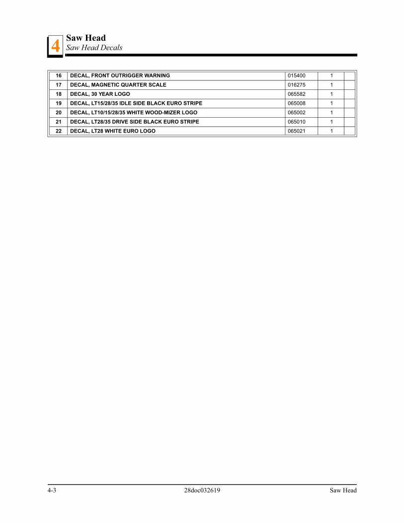
16 DECAL, FRONT OUTRIGGER WARNING 015400 1
17 DECAL, MAGNETIC QUARTER SCALE 016275 1
18 DECAL, 30 YEAR LOGO 065582 1
19 DECAL, LT15/28/35 IDLE SIDE BLACK EURO STRIPE 065008 1
20 DECAL, LT10/15/28/35 WHITE WOOD-MIZER LOGO 065002 1
21 DECAL, LT28/35 DRIVE SIDE BLACK EURO STRIPE 065010 1
22 DECAL, LT28 WHITE EURO LOGO 065021 1
4-3 28doc032619 Saw Head

Saw HeadBlade Housing Covers
Saw Head 28doc032619 4-4
44.3 Blade Housing Covers
REF DESCRIPTION ( Indicates Parts Available In Assemblies Only) PART # QTY.
1 COVER, LT28 DRIVE SIDE BLADE HOUSING (Includes Cover Decals - See Section 4.2) 038480 1
2 BOLT, 1/4-20 X 1/2” HEX HEAD F05005-15 8
3 NUT, 1/4-20 KEPS F05010-9 6
4 LATCH, FLEXIBLE DRAW 014829 2
5 SCREW, #10-24 X 3/8” CROSS SLOTTED ROUND HEAD F05004-3 8
6 NUT, #10-24 SELF-LOCKING HEX F05010-14 8
7 COVER, LT28 IDLE SIDE BLADE HOUSING (Includes Cover Decals - See Section 4.2) 038481 1
8 BLOCK, BLADE VIBRATION DAMPENING 015844 1
9 BOLT, #10 X 3/4” SLOTTED HEX WASHER HEAD F05015-33 2
10 BRACKET WELDMENT, LT15 BELT ENHANCE 074394 1
11 WASHER, 1/4” SAE FLAT F05011-11 2
12 NUT, 3/8-16 JAM F05010-29 1
13 SCREW, 3/8-16 X 1 1/4 SHOP SET F05007-18 1
COVER ASSEMBLY, TOP ENGINE PULLEY 038633 1
14 Cover Weldment, LT15/28 Top Belt Cover 074574 1
15 Plate, Belt Guard Cover 074546 1
16 Bolt, 1/4-20 x 3/4” Hex Head w/Conical Washer F05005-134 4
280023E
9
1
7
2
3
2
3
4
5
6
4
5
6
8
14
11
152
10
12 13
16

Saw HeadSawdust Chute4
4-5 28doc032619 Saw Head
4.4 Sawdust Chute
REF DESCRIPTION ( Indicates Parts Available In Assemblies Only) PART # QTY.
1-6 CHUTE ASSEMBLY, LT28 SAWDUST 038747 1
1 Chute Wldmt, LT28 Sawdust 038746 1
2 Chute, Rubber Sawdust 016727 1
3 Bolt, #10-24x1/2 Self Tap F05015-7 2
4 Bolt, 5/16-18x3/4 HHC F05006-5 2
5 Washer, 5/16 Split Lock F05011-13 2
6 Washer, 5/16 SAE Flat F05011-17 2
7 STRAP, 9IN RUBBER WITH HOOKS 012965 1
8 BOLT, 1/4-20X1 CARRIAGE F05005-34 1
9 WASHER, 1/4 SAE FLAT F05011-11 1
10 NUT, 1/4-20 SWAGED F05010-21 1
1
2
3
4
56
7
89
10
280045-2

Control & Battery BoxesControl Assembly (Optional) 5
SECTION 5 CONTROL & BATTERY BOXES
5.1 Control Assembly (Optional)
REF DESCRIPTION ( Indicates Parts Available In Assemblies Only) PART # QTY.
CONTROL ASSEMBLY, 2017 LT28 POWER FEED 110007 1
1 Weldment, 2017 LT15/28 PF Control Bottom 110006 1
2 Control Module, Power Feed with Heatsink 073547 1
280056-4
1
2
5
7
8
9
10
11
17
13
14
15
16
12
18
3
4
19
20
21
2223
24
2526
6
27
Control & Battery Boxes 28doc032619 5-1

Control & Battery BoxesControl Assembly (Optional)5
3 Nut, 10-24 Hex Nylock F05010-160 4
4 Connector, 1/2” NPT .17-.47” 051299 1
5 Nut, 1/2” NPT Connector Lock E20461 1
6 Switch, Power Feed Drum E20439 1
7 Washer, #8 SAE Flat F05011-41 2
8 Handle, Drum Switch P12500 1
9 Grease Cup, Drum Switch A20463 1
10 Plate, 2017 LT15/28 PF Control Top 110005 1
11 Decal, LT28 Feed Control 2010 059386 1
12 Switch, SPST 25A Toggle 053695 1
13 Washer, 1/2” x 3/4” x 1/16” Nylon P05251-1 2
14 Boot, Toggle Switch P02575 1
15 O-Ring, 3/8” Neoprene 050369 1
16 Light, Green 12V .187 Tabs E20483 1
17 Pot Assembly, Feed Rate Control A07793 1
18 Knob, Speed Control P06257 1
19 Screw, #10-24 x 1/2” Philips Pan Head Type 23 F05015-17 10
20 Cover, Toggle Safety Switch - Orange 114034 1 1
Fuseholder, ATO 12AWG Radial Leads 052164 1
Fuse, 40A ATO Blade Orange 024150-40 1
21 PLATE, POWER FEED CONTROL MOUNT 059595 1
22 BOLT, 5/16-18 X 3/4” HEX HEAD F05006-5 3
23 WASHER, 5/16” SPLIT LOCK F05011-13 3
24 WASHER, 5/16” SAE FLAT F05011-17 3
25 BOLT, 3/8-16 X 1 1/4” HEX HEAD GRADE 5 F05007-123 2
26 WASHER, 3/8” SAE FLAT F05011-3 2
27 NUT, 3/8-16 HEX NYLON LOCK F05010-10 2
1 Added after 7/6/2020.
5-2 28doc032619 Control & Battery Boxes

Control & Battery BoxesBattery Box Assembly 5
5.2 Battery Box Assembly
REF DESCRIPTION ( Indicates Parts Available In Assemblies Only) PART NUMBER QTY.
BATTERY BOX ASSEMBLY, LT28 049124 1
1 Battery, Deka 12V 526MF 540CCA 665CA 028004 1
2 Terminal, Positive Battery 033358 1
3 Terminal, Negative Battery 033359 1
4 Box Weldment, LT28 Battery 049125 1
5 Cover, LT28 Battery 049130 1
6 Nut, 1/4-20 Wing F05010-13 2
7 Washer, 1/4” SAE Flat F05011-11 2
8 Grommet, 5/8 Wire P04137 1
9 Bolt, 5/16-18 x 8” Hex Head Grade 5 F05006-121 2
10 Washer, 5/16” SAE Flat F05011-17 2
1
4
23
5
18
7
7
6
280025F
23
9
10
11 12
13
14
15
15
16
16
178
2022
19
21
PF28
242526
2527
26
Control & Battery Boxes 28doc032619 5-3
Control & Battery BoxesBattery Box Assembly5
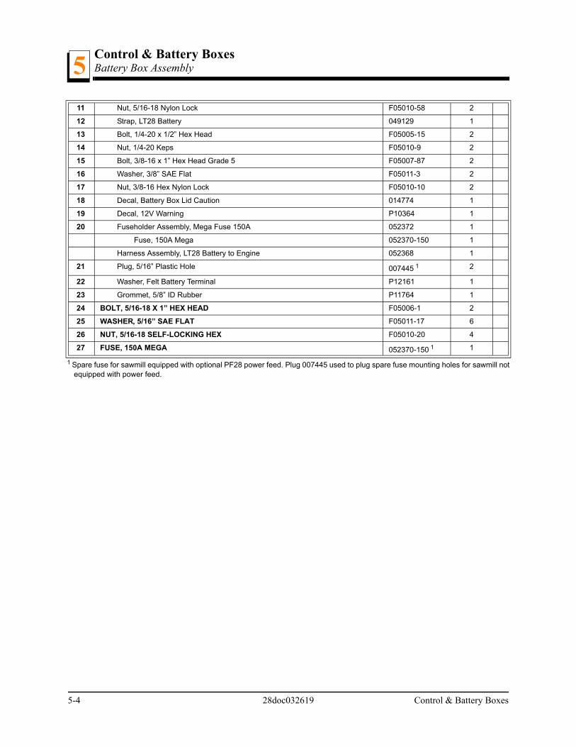
11 Nut, 5/16-18 Nylon Lock F05010-58 2
12 Strap, LT28 Battery 049129 1
13 Bolt, 1/4-20 x 1/2” Hex Head F05005-15 2
14 Nut, 1/4-20 Keps F05010-9 2
15 Bolt, 3/8-16 x 1” Hex Head Grade 5 F05007-87 2
16 Washer, 3/8” SAE Flat F05011-3 2
17 Nut, 3/8-16 Hex Nylon Lock F05010-10 2
18 Decal, Battery Box Lid Caution 014774 1
19 Decal, 12V Warning P10364 1
20 Fuseholder Assembly, Mega Fuse 150A 052372 1
Fuse, 150A Mega 052370-150 1
Harness Assembly, LT28 Battery to Engine 052368 1
21 Plug, 5/16” Plastic Hole 007445 1 2
22 Washer, Felt Battery Terminal P12161 1
23 Grommet, 5/8” ID Rubber P11764 1
24 BOLT, 5/16-18 X 1” HEX HEAD F05006-1 2
25 WASHER, 5/16” SAE FLAT F05011-17 6
26 NUT, 5/16-18 SELF-LOCKING HEX F05010-20 4
27 FUSE, 150A MEGA 052370-150 1 1
1 Spare fuse for sawmill equipped with optional PF28 power feed. Plug 007445 used to plug spare fuse mounting holes for sawmill notequipped with power feed.
5-4 28doc032619 Control & Battery Boxes

Up/Down SystemSaw Head Mount 6
SECTION 6 UP/DOWN SYSTEM
6.1 Saw Head Mount
REF DESCRIPTION ( Indicates Parts Available In Assemblies Only) PART # QTY.
BOX ASSEMBLY, LT28 MAST 048555 1
1 Adjustment Weldment, Head LT28 048562 1
2 Nut, 1/2-13 Half Nylon Lock F05010-127 2
3 Bolt, 1/2-13x2 Carriage F05008-132 2
4 Bearing, .9843” x 2.4409” x .6693” P08066 4
5 Ring, 25mm 5100-98 OR F04254-26 1
6 Plate, Clutch Handle 003327 1
7 Knob, 5/8-18 Ball P04211 1
8 Nut, 1/2-13 Nylon Hex Lock F05010-8 1
9 Bearing, SF1260-6 Bronze P08060 1
10 Washer, 33/64 x 1 3/4 x 1/32 Nylon 014972 1
11 Rod, 5/16-24 Male End P09814 1
12 Rod, 5/16-24 Female End P09813 1
13 Bolt, 5/16-18 x 1 1/2” Hex Head F05008-96 2
14 Nut, 5/16-18 Nylon Lock F05010-58 2
1
2
3
4
4 5
5
6
7
8
9 1011
1213
14
15
16
17
1819
20
20
18
19
20
20
21
2216
181920
23
23
1621
21
17
17
17
24
25
26
2627
284
4
29
3031
31
31 32
33
34
35
36
37
280030D
38
Up/Down System 28doc032619 6-1

Up/Down SystemSaw Head Mount6
15 Bolt, 3/8-16 x 1 1/4” Hex Head Grade 5 F05007-123 1
16 Washer, 3/8” SAE Flat F05011-3 7
17 Nut, 3/8-16 Hex Nylon Lock F05010-10 5
18 Shaft, Bearing Mount 048559 3
19 Bearing, 5/8” x 1.7548” x .4724” P06030-1 3
20 Ring, 5/8” OR 5100-62 F04254-2 6
21 Washer, 3/8” Split Lock F05011-4 8
22 Bolt, 3/8-16 x 1” Hex Head Grade 5 F05007-87 6
23 Bolt, 3/8-16 X 6 1/2” Hex Head Grade 5 F05007-205 3
24 Tensioner Weldment, Power Feed Chain 015721 1
25 Block, Chain Tensioner Mount 048571 1
26 Nut, 1/2-20 Hex Jam F05010-16 2
27 Washer, 1/2” Split Lock F05011-9 1
28 Shaft, Fixed Mount 048560 1
29 Bolt, 3/8-16 x 2 3/4” Hex Head Grade 5 F05007-206 2
30 Screw, 3/8-16x1 Scoket Head Set Brass Tip F05007-88 2
31 Nut, 3/8-16 Jam F05010-29 2
32 Bolt, 3/8-16 x 1 1/2” Hex Head Full Thread F05007-17 2
33 Plate, Scale Mount 049133 1
34 Bolt, 5/16-18 x 3/4” Hex Head F05006-102 2
35 Washer, 5/16” Split Lock F05011-13 2
36 Washer, 5/16” SAE Flat F05011-17 2
37 Box Weldment, LT28 Mast 048556 1
38 Bolt, 3/8-16 x 1 3/4” Hex Head Full Thread F05007-19 1
6-2 28doc032619 Up/Down System

Up/Down SystemManual Crank Assembly 6
6.2 Manual Crank Assembly
REF DESCRIPTION ( Indicates Parts Available In Assemblies Only) PART # QTY.
UP/DOWN ASSEMBLY, LT28 REDUCER 054606 1
1 Shaft Weldment, LT28 Up/Down Reduced 054604 1
2 Bearing, Needle 1/2” x 3/4” Single Seal 049331 4
3 Plate, Up/Down Lock 054609 1
4 Bolt, 1/4-20 x 1” Hex Head Grade 5 F05005-101 6
5 Washer, 1/4” SAE Flat F05011-11 8
6 Nut, 1/4-20 Hex Nylon Lock F05010-69 8
Handle Kit, LT28 Retro 038751 1
7 Handle Weldment, Up/Down LT28 049333 1
8 Ring, 1/2” E-Clip Retaining P10649 1
9 Washer, 1/2” SAE Flat F05011-2 1
10 Spring, .72” OD x .065” WD x 1.00” 038457 1
11 Shaft, Up/Down Handle 049335 1
12 Handle, 25/32 x 1 1/4 x 4 3/4 Plastic 049336 1
13 Pin, 3/16” x 1” Roll F05012-11 4
14 Plate, Handle Lock Release 046867 1
15 Collar, Lock 1/2” ID x 7/8” OD 014820 1
16 Plate, Pointer Up/Down 048598 1
17 Bolt, 1/4-20 x 1 1/4” Hex Head Full Thread Cap F05005-3 1
18 Chain, #40 x 88 1/2” Up/Down 038476 1
19 Link, #40 Master P04200 2
20 Chain, #40 x 22” Reduction 038599 1
21 Extension Weldment, LT28 Up/Down Reducer 054602 1
1
2
2
2
2
3
4
5
6
7
13
89
10
11
12
14
15
16
17
18
19 19
1313
6
6
4
4
20
5
5
55
5
22
24
23
23
25
21
26
27
27
28
29
280041C
Up/Down System 28doc032619 Page 3

Up/Down SystemManual Crank Assembly6
22 Fitting, 1/4-28 Grease P05060 1
23 Tube, Chain Guard 054612 2
24 Sprocket, 40B x .50” Modified 038598 1
25 Shaft Weldment, Up/Down 16T 054600 1
26 Cover, Up/Down Reducer Chain 054611 1
27 Bolt, 1/4-20 x 3” Hex Head Grade 5 F05005-127 2
28 Decal, Gear Reduced Blade Height 054588 1
29 Nut, 1/4-20 Keps F05010-9 2
Page 4 28doc032619 Up/Down System

Up/Down System6
6.3 Up/Down Assist Assembly
REF DESCRIPTION ( Indicates Parts Available In Assemblies Only) PART # QTY.
ASSIST ASSEMBLY, LT28 UP/DOWN 038906 1
1 Spring, Gas Charged 046982 2
Wiper, .542” Gas Spring Rubber 038628 1
2 Block, Lower Spring Mount 038905 2
3 Pulley, Large Cable 046602 1
4 Ring, 1 1/8” Inside Retaining F04254-1 1
5 Bushing, 3/16” Spacer 046986 4
6 Bearing, R8-2RS 015975 2
1
2
3 4
55
6
78
910
11
12
13
13
8
15
567
8
16
17
18
19
19
20
21
22
280050B
23
14
Up/Down System doc032619 6-5

Up/Down System6
7 Bolt, 1/2” x 1” Shoulder F05008-146 28 Nut, 3/8-16 Hex Nylon Lock F05010-10 3
9 Washer, 5/16” SAE Flat F05011-17 2
10 Bolt, 5/16-18 x 1 3/4” Hex Head Full Thread Grade 5 F05006-79 4
11 Nut, 5/16-18 Hex Lock F05010-6 4
12 Pad, Assist Guide Wear 038913 1
13 Plate, Lower Pulley Mount 038907 2
14 Pad, Up/Down Assist Slide 025674 1
15 Pulley, Small Cable 046995 1
16 Cable Assembly, Up/Down LT28 038908 1
17 Nut, 3/8-16 Hex F05010-1 1
18 Sprocket, #40 Idler 17T 5/8 ID P04333 1
19 Washer, 5/8” SAE Flat F05011-5 2
20 Cover, Upper Chain 049330 1
21 Bolt, 5/8-11 x 2 1/2” Hex Head Grade 5 F05009-20 1
22 Nut, 5/8-11 Nylon Lock F05010-34 1
23 Mount Weldment, Upper Assist 038903 1
6-6 doc032619 Up/Down System

Feed System & Track RollersTrack Rollers And Wipers 7
SECTION 7 FEED SYSTEM & TRACK ROLLERS
7.1 Track Rollers And Wipers
REF DESCRIPTION ( Indicates Parts Available In Assemblies Only) PART # QTY.
UPRIGHT ASSEMBLY, LT28 048543 1
1 Bearing, MG305DDA 023857 2
2 Ring, 1” Outer Retaining F04254-15 2
3 Bearing, Cam Follower 1 1/2” (McGill) 012797 2
4 Collar, 5/8” x 1-1/8” Lock P05035 2
5 Cover Weldment, Rear Bearing 049342 1
6 Cover Weldment, Front Bearing 049341 1
7 Wiper, Top Rail M04113 2
12
1
2
3
4
3
4
5
6
78
7
8
9
9
10 11
10
11
12
13
13
11
11
14
15
16
18
17
17
32
17
33
35
36
34
19
24
24
280026E
22
23
2728
2323
23
29
25
3031
26
20 21
37
38
39
4041 42
Feed System & Track Rollers 28doc032619 7-1

Feed System & Track RollersTrack Rollers And Wipers7
8 Plate, Track Wiper 034229 2
9 Stud, 1/4-20 X 5/8” Wing F05005-64 2
10 Bolt, 1/4-20 X 1 3/4” Hex Head Grade 5 F05005-68 2
11 Washer, 1/4 SAE Flat F05011-11 4
12 Plate, LT28 Blade Height Pointer Mount 049134 1
13 Bolt, 1/4-20 X 1/2” Hex Head F05005-15 2
Bearing Assembly, Lower LT28 048547 1
14 Bearing Weldment, LT28 Lower Cam 048548 1
15 Bearing, Cam Follower 1 1/2 (McGill) 012797 1
16 Nut, 5/8-18 Hex Jam F05010-11 1
17 Bolt, 3/8-16 x 1” Hex Head Grade 5 F05007-87 8
18 Bolt, 3/8-16 x 1 1/4” Hex Head Grade 5 F05007-123 4
19 Nut, 3/8-16 Hex Nylon Lock F05010-10 8
20 Nut, 1/2-13 Hex Jam F05010-31 1
21 Bolt, 1/2-13 x 1 1/2” Hex Head Grade 5 F05008-33 1
22 Bolt, 3/8 x 4 Hex Head Full Thread Grade 5 F05007-92 2
23 Washer, 3/8” SAE Flat F05011-3 8
24 Nut, 3/8-16 Hex Nylon Lock F05010-10 4
25 Nut, 1/4-20 Nylon Lock F05010-69 1
26 Pointer, Scale Height 017778 1
27 Bolt, #10-24 x 3/8” CrSl PH F05004-3 2
28 Nut, #10-24 Keps F05010-14 2
29 Clamp, 1-1/4 Carbon Steel Conduit 038482 1
30 Bolt, 1/4-20 x 1” Hex Head Grade 5 F05005-101 1
31 Washer, 1/4” SAE Flat F05011-11 1
32 Angle, LT28 Mast Tube Stainless 048614 4
33 Bolt, 1/2-13 x 2 1/2” Hex Head Grade 5 F05008-74 1
34 Nut, 1/2-13 Jam F05010-31 1
35 Fitting, 1/4-28 Grease P05060 1
36 Decal, Saw Head Up/Down Caution S11762 1
Cover Assembly, LT28/35/70 Track 110614 1
37 Cover, Mid Track, LT28, LT35, LT70 110610 1
38 Retainer, Felt Oiler 110611 1
39 Bolt, 1/4-20x3/4 Carriage F05005-113 4
40 Nut, 1/4-20 Nylock F05010-69 4
41 Washer, 1/4 SAE Flat F05011-11 4
42 Felt, Middle Track Oiler LT40/50/70 S09915 1
7-2 28doc032619 Feed System & Track Rollers
Feed System & Track RollersManual Feed 7
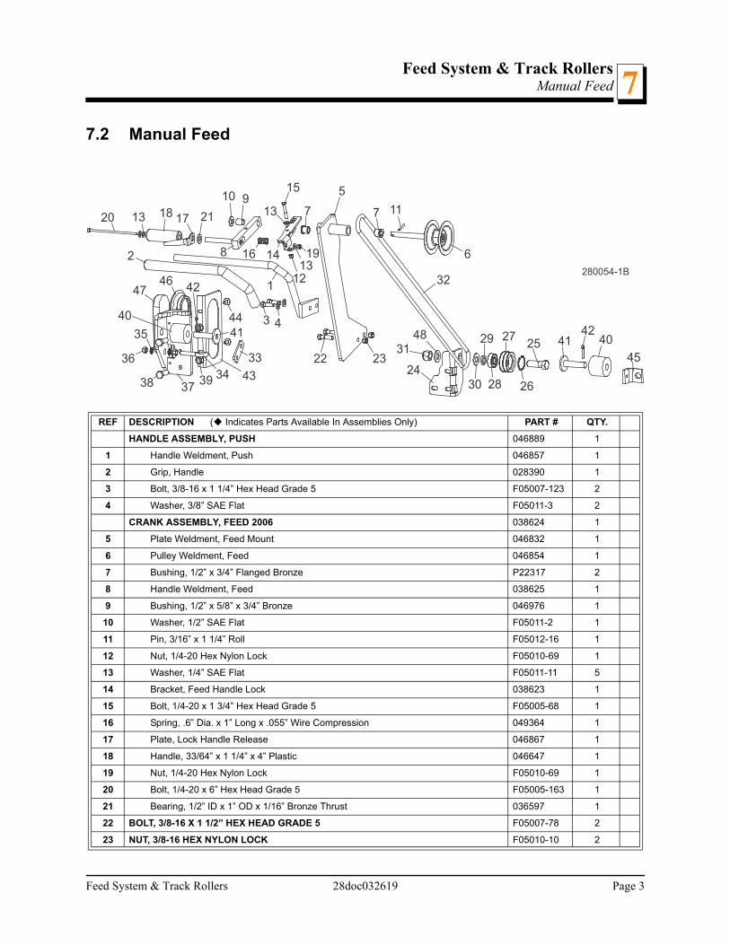
7.2 Manual Feed
REF DESCRIPTION ( Indicates Parts Available In Assemblies Only) PART # QTY.
HANDLE ASSEMBLY, PUSH 046889 1
1 Handle Weldment, Push 046857 1
2 Grip, Handle 028390 1
3 Bolt, 3/8-16 x 1 1/4” Hex Head Grade 5 F05007-123 2
4 Washer, 3/8” SAE Flat F05011-3 2
CRANK ASSEMBLY, FEED 2006 038624 1
5 Plate Weldment, Feed Mount 046832 1
6 Pulley Weldment, Feed 046854 1
7 Bushing, 1/2” x 3/4” Flanged Bronze P22317 2
8 Handle Weldment, Feed 038625 1
9 Bushing, 1/2” x 5/8” x 3/4” Bronze 046976 1
10 Washer, 1/2” SAE Flat F05011-2 1
11 Pin, 3/16” x 1 1/4” Roll F05012-16 1
12 Nut, 1/4-20 Hex Nylon Lock F05010-69 1
13 Washer, 1/4” SAE Flat F05011-11 5
14 Bracket, Feed Handle Lock 038623 1
15 Bolt, 1/4-20 x 1 3/4” Hex Head Grade 5 F05005-68 1
16 Spring, .6” Dia. x 1” Long x .055” Wire Compression 049364 1
17 Plate, Lock Handle Release 046867 1
18 Handle, 33/64” x 1 1/4” x 4” Plastic 046647 1
19 Nut, 1/4-20 Hex Nylon Lock F05010-69 1
20 Bolt, 1/4-20 x 6” Hex Head Grade 5 F05005-163 1
21 Bearing, 1/2” ID x 1” OD x 1/16” Bronze Thrust 036597 1
22 BOLT, 3/8-16 X 1 1/2” HEX HEAD GRADE 5 F05007-78 2
23 NUT, 3/8-16 HEX NYLON LOCK F05010-10 2
1
2
3 4
5
6
30
32
7910
11
8
12
14
15
16
171813
22 2324
3148
19
1320
280054-1B
7
25
26
27
28
29
13
21
3334
35
36
3738
4041
42
43
44
45
404142
39
4647
Feed System & Track Rollers 28doc032619 Page 3

Feed System & Track RollersManual Feed7
24 PLATE, PULLEY MOUNT 048580 1
ROLLER ASSEMBLY, LOWER FEED 046979 1
25 Bolt, 5/8-11 X 2” Hex Head Grade 2 F05009-2 1
26 Ring, 1.575 Internal Beveled Retaining F04254-8 1
27 Roller, 2 1/4 Double Groove 046838 1
28 Bearing, 5/8 x 1.7548 x .4724 P06030-1 1
29 Tube, 41/64 x 1 x 3/16 S12480 1
30 Washer, 5/8” SAE Flat F05011-5 1
31 Nut, 5/8-11 Nylon Lock F05010-34 1
32 ROPE, 3/8” DIA. SOLID BRAIDED POLYESTER R02080-1 30.5 Ft.
33 PLATE, FEED ROPE LOCK 049339 1
34 BOLT, 3/8-16 X 2” EYE (5/8” ID) F05007-30 1
35 WASHER, 3/8” SPLIT LOCK F05011-4 2
36 NUT, 3/8-16 HEX F05010-1 2
37 BRACKET WELDMENT, REAR FEED STOP 006686 1
38 BOLT, 1/2-13 X 1 1/2” HEX HEAD F05008-33 2
39 NUT, 1/2-13 HEX NYLON LOCK F05010-8 2
40 BUSHING, 11/16” ID X 2 1/8” OD X 1 3/4” RUBBER P12165 2
41 PIN WELDMENT, CARRIAGE STOP W09293 2
42 PIN, 3/16” X 1” COTTER F05012-21 2
43 PLATE, BED TUBE END W/LIGHT MOUNT 057882 1
44 SCREW, 1/4-20 X 3/4” HEX W/CONICAL WASHER HEAD F05005-134 2
45 BRACKET, FEED ROPE MOUNT S12466 1
46 GROMMET, 6 1/2” LIGHT MOUNTING 006688 1
47 LIGHT, 8 DIODE LED TAIL 006391 1
48 WASHER, 5/8” SAE FLAT F05011-5 1
Page 4 28doc032619 Feed System & Track Rollers

Feed System & Track RollersPower Feed Assembly (Optional)
Feed System & Track Rollers 28doc032619 7-5
77.3 Power Feed Assembly (Optional)
REF DESCRIPTION ( Indicates Parts Available In Assemblies Only) PART # QTY.
1 BOSS, .63” ID X 1” OD X .85” 008958 1
2 BOLT, IDLER SPROCKET RETAINING 008959 1
3 BRACKET, POWER FEED DRIVE MOUNT 008973 1
4 PLATE, POWER FEED DRIVE MOUNT 059593 1
5 SPROCKET, 40B28 X 3/4” BORE 059594 1
6 MOTOR ASSEMBLY, LT28 POWER FEED 069361 1
Brush Kit, Klauber 33:1 Gearmotor Endbell 065182 1
7 BOLT, 5/16-18 X 3/4” HEX HEAD GRADE 5 F05006-102 4
8 WASHER, 5/16” SPLIT LOCK F05011-13 4
9 BOLT, 3/8-16 X 1 1/4” HEX HEAD GRADE 5 F05007-123 1
10 BOLT, 3/8-16 X 1 1/4” CARRIAGE HEAD GRADE 5 F05007-127 2
11 WASHER, 3/8” SAE FLAT F05011-3 4
12 NUT, 3/8-16 HEX NYLON LOCK F05010-10 3
13 SPROCKET, #40 17T X 5/8” BORE IDLER P04333 1
14 NUT, 5/8-11 HEX NYLON LOCK F05010-34 1
1
2
3
4
5
6
78
9
10
11
12
13
14
280056-2

Power Feed SystemFeed Chain/Stop7
7-6 28doc032619 Power Feed System
7.4 Feed Chain/Stop
REF DESCRIPTION ( Indicates Parts Available In Assemblies Only) PART # QTY.
1 CHAIN, #40 X 267.5" LT40 FEED 014745 1
2 LINK, #40 MASTER P04200 2
3 TENSIONER WELDMENT, POWER FEED CHAIN 015721 1
4 WASHER, 1/2” SAE FLAT F05011-2 3
5 WASHER, 1/2” SPLIT LOCK F05011-9 3
6 BOLT, 1/2-13 X 1” HEX HEAD GRADE 8 F05008-128 3
7 NUT, 1/2-20 HEX JAM F05010-16 2
8 WASHER, 1/2" SPLIT LOCK F05011-9 2
9 BRACKET WELDMENT, REAR FEED STOP 006686 1
STOP KIT, RUBBER CARRIAGE K09630 2
10 Stop, Rubber Carriage P12165 1
11 Pin, Rubber Carriage Stop W09293 1
12 Pin, 3/16" X 1" Cotter F05012-21 1
13 BOLT, 1/4-20 X 3/4” WITH CONICAL WASHER F05005-134 1
14 PLATE, BED TUBE END W/LIGHT MOUNT 057822 1
15 BRACKET, FRONT FEED CHAIN MOUNT 015008 1
16 BOLT, 3/8-16 X 1” HEX HEAD GRADE 5 F05007-87 2
17 NUT, 3/8-16 HEX NYLON LOCK F05010-10 2
18 GROMMET, 6 1/2” LIGHT MOUNTING 006688 1
19 LIGHT, 8 DIODE LED TAIL 006391 1
1
22
3
5
88
7
10
14
15
16
17
SM0353-1
912
13
13
6
7
4
11
1819

Bed Frame AssemblyBed Rail Assembly, Front And Rear 8
SECTION 8 BED FRAME ASSEMBLY
8.1 Bed Rail Assembly, Front And Rear
REF DESCRIPTION ( Indicates Parts Available In Assemblies Only) PART # QTY.
BED RAIL ASSEMBLY, REAR PAINTED A09774 1
1 Bed Rail Tube, Long S09102 1
2 Pin, Ramp Mount S04030 1
3 Block, Log Stop S09034 1
4 Nut, 5/8-11 Pilot Weld F05010-84 2
5 Nut, 5/8-11 Hex F05010-5 2
6 Bolt, Bed Rail Adjustment S13006 2
7 Plate, Bed Rail End Cap S04058 2
BED RAIL ASSEMBLY, FRONT PAINTED A09564 1
8 Bed Rail Tube, Long S09102 1
9 Pin, Ramp Mount S04030 1
10 Block, Log Stop S09034 1
11 Tube, Ramp Retainer Mount S09334 1
1
7
2
3
5
6
8
15
9
10
11
12
14
1618
19
1718
1617
19
191817
16
20
21
22
20
21
22
230025-2
13
4
23
2425
Bed Frame Assembly doc032619 8-1

Bed Frame AssemblyBed Rail Assembly, Front And Rear8
12 Nut, 5/8-11 Pilot Weld F05010-84 2
13 Nut, 5/8-11 Hex F05010-5 2
14 Bolt, Bed Rail Adjustment S13006 2
15 Plate, Bed Rail End Cap S04058 2
16 BOLT, 1/2-13 X 4" HEX HEAD GRADE 5 F05008-78 3
17 BOLT, 1/2-13 X 3 1/2” CARRIAGE F05008-94 1 1
18 WASHER, 1/2" SAE FLAT F05011-2 7
19 NUT, 1/2-13 NYLON LOCK F05010-8 4
COVER KIT, FRONT/REAR BED RAIL SS 079144 2
20 Cover, Stainless Steel Bed Rail 016898 1
21 Bolt, 5/16-18 X 2 1/2" Hex Head F05006-10 3
22 Nut, 5/16-18 Hex Lock F05010-6 3
23 WRENCH, BED RAIL ADJUSTMENT 015970 1
24 CAP, BED RAIL REMOVABLE END 038843 2
25 BOLT, 1/4-20 X 3/4” W/CONICAL WASHER HEAD F05005-134 2
1 Used on rear bed rail to allow clearance for optional side support rollers.
8-2 doc032619 Bed Frame Assembly
Bed Frame AssemblyBed Rail Assembly, Middle Front
Bed Frame Assembly doc032619 8-3
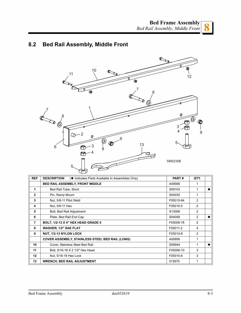
88.2 Bed Rail Assembly, Middle Front
REF DESCRIPTION ( Indicates Parts Available In Assemblies Only) PART # QTY.
BED RAIL ASSEMBLY, FRONT MIDDLE A09566 1
1 Bed Rail Tube, Short S09103 1
2 Pin, Ramp Mount S04030 1
3 Nut, 5/8-11 Pilot Weld F05010-84 2
4 Nut, 5/8-11 Hex F05010-5 2
5 Bolt, Bed Rail Adjustment S13006 2
6 Plate, Bed Rail End Cap S04058 2
7 BOLT, 1/2-13 X 4" HEX HEAD GRADE 5 F05008-78 2
8 WASHER, 1/2" SAE FLAT F05011-2 4
9 NUT, 1/2-13 NYLON LOCK F05010-8 2
COVER ASSEMBLY, STAINLESS STEEL BED RAIL (LONG) A09956 1
10 Cover, Stainless Steel Bed Rail S09944 1
11 Bolt, 5/16-18 X 2 1/2" Hex Head F05006-10 3
12 Nut, 5/16-18 Hex Lock F05010-6 3
13 WRENCH, BED RAIL ADJUSTMENT 015970 1
1
6
2
3
4
5
43
5
7
8
8
9
78
9
1011
12
13
SM0235B

Bed Frame AssemblyBed Rail Assembly, Middle Rear8
8.3 Bed Rail Assembly, Middle Rear
REF DESCRIPTION ( Indicates Parts Available In Assemblies Only) PART # QTY.
BED RAIL ASSEMBLY, REAR MIDDLE A09565 1
1 Bed Rail Tube, Short 014640 1
2 Block, Log Stop w/Threaded Hole 014639 1
3 Bolt, 3/8-16 x 1 1/2 Full Thead Hex Head F05007-17 1
4 Nut, 3/8-16 Hex Jam F05010-29 1
5 Pin, Ramp Mount S04030 1
6 Tube, Ramp Retainer Mount S09334 1
7 Nut, 5/8-11 Pilot Weld F05010-84 2
8 Nut, 5/8-11 Hex F05010-5 2
9 Bolt, Bed Rail Adjustment S13006 2
10 Plate, Bed Rail End Cap S04058 2
11 BOLT, 1/2-13 X 4" HEX HEAD GRADE 5 F05008-78 2
12 WASHER, 1/2" SAE FLAT F05011-2 4
1
2
34
56
8
7
8
9
9
11
10
11
12
12
13
1312
12
250038D
1415
16
15
16
17
8-4 doc032619 Bed Frame Assembly

Bed Frame AssemblyBed Rail Assembly, Middle Rear 8
13 NUT, 1/2-13 NYLON LOCK F05010-8 2
COVER ASSEMBLY, STAINLESS STEEL BED RAIL (LONG) A09956 1
14 Cover, Stainless Steel Bed Rail S09944 1
15 Bolt, 5/16-18 X 2 1/2" Hex Head F05006-10 3
16 Nut, 5/16-18 Hex Lock F05010-6 3
17 WRENCH, BED RAIL ADJUSTMENT 015970 1
Bed Frame Assembly doc032619 8-5
Bed Frame AssemblyLeg Assembly8
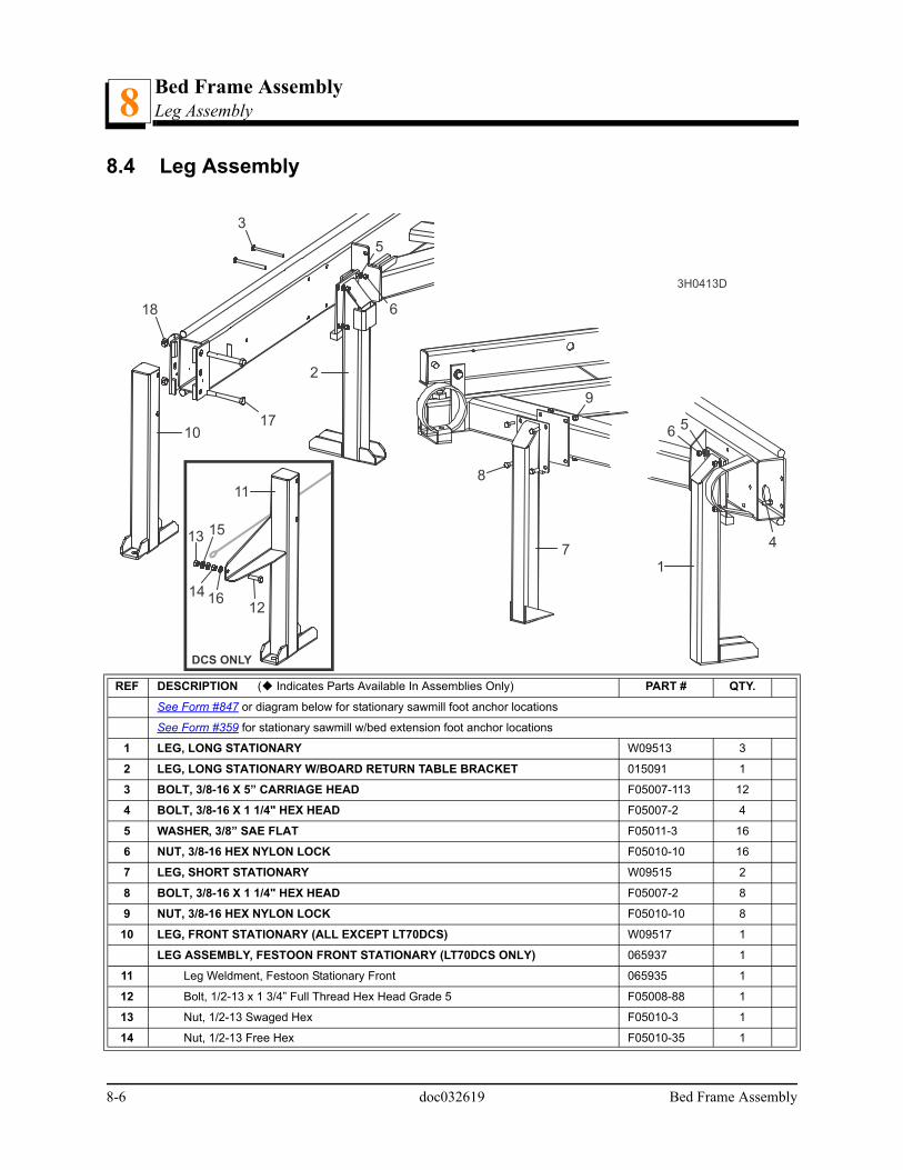
8.4 Leg Assembly
REF DESCRIPTION ( Indicates Parts Available In Assemblies Only) PART # QTY.
See Form #847 or diagram below for stationary sawmill foot anchor locations
See Form #359 for stationary sawmill w/bed extension foot anchor locations
1 LEG, LONG STATIONARY W09513 3
2 LEG, LONG STATIONARY W/BOARD RETURN TABLE BRACKET 015091 1
3 BOLT, 3/8-16 X 5” CARRIAGE HEAD F05007-113 12
4 BOLT, 3/8-16 X 1 1/4" HEX HEAD F05007-2 4
5 WASHER, 3/8” SAE FLAT F05011-3 16
6 NUT, 3/8-16 HEX NYLON LOCK F05010-10 16
7 LEG, SHORT STATIONARY W09515 2
8 BOLT, 3/8-16 X 1 1/4" HEX HEAD F05007-2 8
9 NUT, 3/8-16 HEX NYLON LOCK F05010-10 8
10 LEG, FRONT STATIONARY (ALL EXCEPT LT70DCS) W09517 1
LEG ASSEMBLY, FESTOON FRONT STATIONARY (LT70DCS ONLY) 065937 1
11 Leg Weldment, Festoon Stationary Front 065935 1
12 Bolt, 1/2-13 x 1 3/4” Full Thread Hex Head Grade 5 F05008-88 1
13 Nut, 1/2-13 Swaged Hex F05010-3 1
14 Nut, 1/2-13 Free Hex F05010-35 1
DCS ONLY
1
2
3
4
5
6
56
7
8
9
10
11
12
13
1614
15
17
18
3H0413D
8-6 doc032619 Bed Frame Assembly

Bed Frame AssemblyLeg Assembly 8
15 Washer, 1/2” SAW Flat F05011-2 2
16 Washer, 1/2” Split Lock F05011-9 1
17 BOLT, 5/8-11 X 5 1/2" HEX HEAD GRADE 5 (ALL EXCEPT LT70DCS) F05009-11 2
18 NUT, 5/8-11 HEX LOCK (ALL EXCEPT LT70DCS) F05010-4 2
SM0426
0150
91W
0951
3
W09
517
(A
ll E
xce
pt
LT70
DC
S)
065
937
(LT
70D
CS
On
ly)
W09
513
W09
513
W09
515
W09
515
0150
91W
0951
3
W09
517
W09
513
W09
513
W09
515
W09
515
Bed Frame Assembly doc032619 8-7

Bed Frame AssemblyPivot Bed Rail Assembly8
8-8 doc032619 Bed Frame Assembly
8.5 Pivot Bed Rail Assembly
REF DESCRIPTION ( Indicates Parts Available In Assemblies Only) PART # QTY.
PIVOT BED RAIL ASSEMBLY (LT28) A13015 2
1 Pivot Bed Rail Weldment (LT28) W13014 1
2 Nut, 5/8-11 Pilot Weld F05010-84 2
3 Nut, 5/8-11 Hex F05010-5 2
4 Bolt, Bed Rail Adjustment S13006 2
5 Bracket, Pivot Rail Mounting W13090 1
6 Bolt, 1/2-13 x 1” Hex Head Grade 2 F05008-50 1
7 Washer, 9/16” SAE Flat F05011-52 1
8 Nut, Pivot Rail Adjustment S13016 1
9 Screw, 1/4-28 x 1/4” Brass Tip Set F05005-42 2
10 Fitting, 3/16” Grease P04107 1
11 BOLT, 3/8-16 X 4 3/4” CARRIAGE HEAD F05007-114 2
12 BOLT, 3/8-16 X 5” CARRIAGE HEAD F05007-113 6
13 WASHER, 3/8” SAE FLAT F05011-3 8
14 NUT, 3/8-16 NYLON LOCK F05010-10 8
COVER KIT, PIVOT RAIL STAINLESS STEEL (LT28) 017710 2
15 Cover, Stainless Steel Pivot Bed Rail (LT28) S13012 1
16 Bolt, 5/16-18 X 2 1/2" Hex Head F05006-10 2
17 Nut, 5/16-18 Hex Lock F05010-6 2
WRENCH, BED RAIL ADJUSTMENT (See Section 8.1) 015970 1
3H0128C
1
67
8
9
4
2
3
15
11
1616
12
12
12
17
17
1413
5
10

Bed Frame AssemblyLog Side Support Assembly 8
8.6 Log Side Support Assembly
REF DESCRIPTION ( Indicates Parts Available In Assemblies Only) PART # QTY.
1 SUPPORT, LOG SIDE 015235 4
2 Fitting, 3/16" Grease P04107 2
MOUNTING KIT, LOG SIDE SUPPORT 016559 4
3 Pin, Log Side Support Pivot 016544 1
4 Bolt, 1/4-20 X 1 1/2" Hex Head Grade 5 F05005-4 1
5 Washer, 1/4" SAE Flat F05011-11 2
6 Nut, 1/4-20 Self Locking F05010-9 1
7 Plate, Log Side Support End 016555 1
8 Bolt, 1/2-13 X 3 1/2" Hex Head Grade 5 F05008-61 2
9 Washer, 1/2" SAE Flat F05011-2 5
10 Nut, 1/2-13 Hex Nylon Lock F05010-8 3
11 Washer, .52” x 1.69” 014632 1
1
3
4
5
5 6
7
8
9
1011
12
2
2
13
1414
15
15
1515
16
17
18
18
SM0271-6B
19
20
2121
22
9
Bed Frame Assembly doc032619 8-9
Bed Frame AssemblyLog Side Support Assembly8
12 Bolt, 1/2-13 X 1 1/2" Hex Head Grade 5 F05008-33 1
13 Plate, Side Support Washer Clamp 016558 1
ROLLER KIT, SIDE SUPPORT 016562 4
14 Roller, Side Support 016561 2
15 Washer, 5/8” SAE Flat F05011-5 1 6
16 Bolt, 5/8-11 x 3 3/4” Hex Head Grade 5 F05009-118 1
17 Nut, 5/8-11 Hex Nylon Lock Jam F05010-96 1
18 Bushing, Bronze 5/8” x 1” x 3/4” 016560 2
Bolt, 1/2-13 x 3 1/2” Carriage Head F05008-94 1
Instruction Sheet, Side Support Roller 016562-526 1
GUARD KIT, STAINLESS STEEL SIDE SUPPORT (OPTIONAL) 016798 1
19 Guard, Stainless Steel Side Support 016722 4
20 Bolt, 1/4-20 x 1 3/4” Hex Head F05005-4 8
21 Washer, 1/4” SAE Flat F05011-11 16
Washer, 5/8” SAE Flat F05011-5 1 4
22 Nut, 1/4-20 Hex Nylon Lock F05010-69 8
Instruction Sheet, Stainless Steel Side Support Guard Retro 016798-1005 1
1 Additional 5/8” SAE Flat Washer F05011-5 may be required on each side of side support to provide clearance for optional stainlesssteel side support guards. Extra washers are included in the stainless steel guard retrofit kit (016798).
8-10 doc032619 Bed Frame Assembly

Bed Frame AssemblySafety Chain Assembly
Bed Frame Assembly doc032619 8-11
88.7 Safety Chain Assembly
REF DESCRIPTION ( Indicates Parts Available In Assemblies Only) PART # QTY.
1 CHAIN, 15 INCH SAFETY 107972 1
2 BOLT, 1/2-13X1 1/2 HEX HEAD GRADE 5 F05008-33 1
3 NUT, 1/2-13 NYLON HEX LOCK F05010-8 1
4 WASHER, 7/16 STANDARD FLAT F05011-35 1
280018B
1
2
3
4

Bed Frame AssemblyBed Frame Decals8
8-12 doc032619 Bed Frame Assembly
8.8 Bed Frame Decals
REF DESCRIPTION ( Indicates Parts Available In Assemblies Only) PART # QTY.
1 DECAL, WOOD-MIZER LOGO S12281 1
2 DECAL, AMBER REFLECTIVE 2” ROUND P07453 2
3 DECAL, KEEP AWAY DANGER S09851 1
4 DECAL, RED REFLECTIVE 2” ROUND P07452 3
5 DECAL, PINCH POINT DANGER P10287 1
6 DECAL, SAW HEAD REST CAUTION S12581 1
7 DECAL, LOG LIMIT STRIPE S12051 2
Potential PinchPoint When CarriageIs Returning
4
KEEP ALL PERSONSA SAFE DISTANCE AWAY
WHILE OPERATINGTHIS MACHINE S09851
2 3
4
4 5 2
6
7 7
2300221
Bed Frame AssemblyLog Clamp
Bed Frame Assembly 28doc032619 8-13
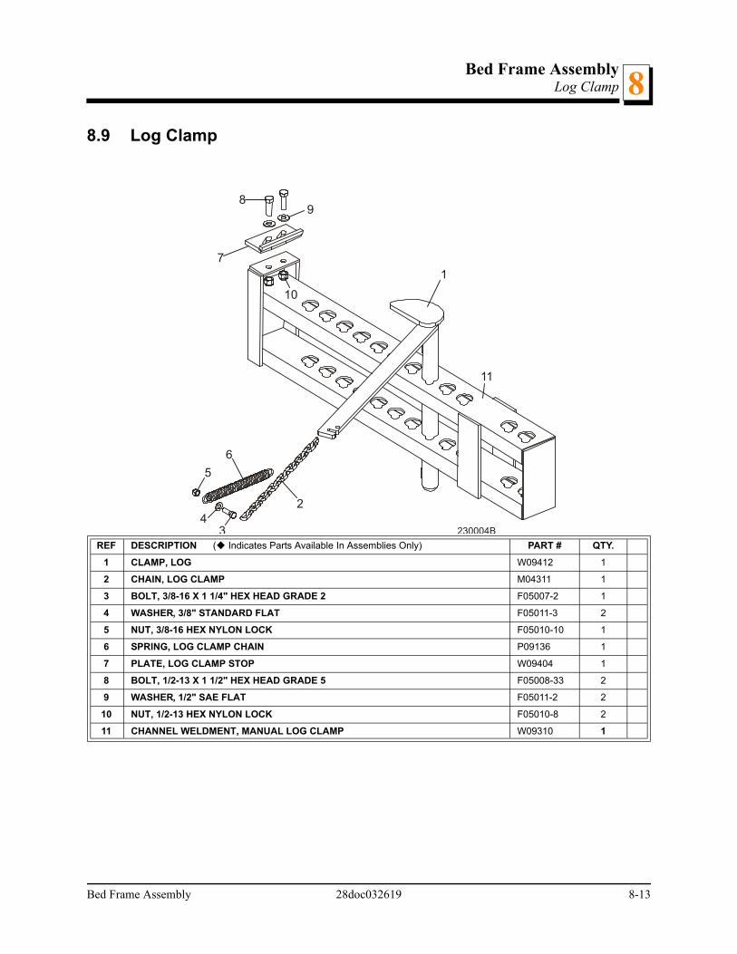
88.9 Log Clamp
REF DESCRIPTION ( Indicates Parts Available In Assemblies Only) PART # QTY.
1 CLAMP, LOG W09412 1
2 CHAIN, LOG CLAMP M04311 1
3 BOLT, 3/8-16 X 1 1/4" HEX HEAD GRADE 2 F05007-2 1
4 WASHER, 3/8" STANDARD FLAT F05011-3 2
5 NUT, 3/8-16 HEX NYLON LOCK F05010-10 1
6 SPRING, LOG CLAMP CHAIN P09136 1
7 PLATE, LOG CLAMP STOP W09404 1
8 BOLT, 1/2-13 X 1 1/2" HEX HEAD GRADE 5 F05008-33 2
9 WASHER, 1/2" SAE FLAT F05011-2 2
10 NUT, 1/2-13 HEX NYLON LOCK F05010-8 2
11 CHANNEL WELDMENT, MANUAL LOG CLAMP W09310 1
1
2
34
5
6
7
89
10
230004B
11

Bed Frame AssemblyLog Loading Ramps8
8-14 28doc032619 Bed Frame Assembly
8.10 Log Loading Ramps
REF DESCRIPTION ( INDICATES PARTS AVAILABLE IN ASSEMBLIES ONLY) PART # QTY.
RAMP KIT, LOG LOADING WITH RETAINERS K09466 1
1 Ramp, Log Loading W09014 2
Retainer Kit, Log Ramp K09810 2
2 Retainer, Log Ramp W09413 1
3 Spring, Log Ram Retainer P09335 1
4 Washer, 5/8" I.D. x .100" Thick Nylon F05011-19 1
5 Pin, 3/16" x 1" Roll F05012-11 1

Bed Frame AssemblyBoard Outfeed Table (Optional)
Bed Frame Assembly doc032619 8-15
88.11 Board Outfeed Table (Optional)
REF DESCRIPTION ( Indicates Parts Available In Assemblies Only) PART # QTY.
TABLE ASSEMBLY, BOARD OUTFEED 016652 1
1 Table Weldment, Board Outfeed 016606 1
2 Roller, 2 1/2” x 25” 038167 6
3 Mount Weldment, Outfeed Table Leg 016609 2
4 Leg Weldment, Outfeed Table 016651 4
5 Pin, 3/8” x 2 1/4” Square Wire Lock 014151 4
6 Pin, Snap - Coil Tension 016677 4
7 Bolt, 3/8-16 x 3 1/4” Hex Head F05007-135 4
8 Nut, 3/8-16 Hex Nylon Lock F05010-10 4
9 Decal, Hand Pinch Point Warning S12641 4
10 Decal, 1 1/2” Wood-Mizer Logo 016991 2
1
2
3
4
4
3
5
5
6
6
78
87
9
9
9
10
10
SM0316

MiscellaneousReplacement Manuals9
SECTION 9 MISCELLANEOUS
9.1 Replacement Manuals
REF DESCRIPTION ( Indicates Parts Available In Assemblies Only) PART # QTY.
Wood-Mizer Product Information
1 ALL-PRODUCTS CATALOG PS750 1
Basic Sawmill Manuals
2 TRU-SHARP BLADE HANDBOOK M600 1
3 WOOD-MIZER GENERAL INFORMATION M601 1
4 LT28 OPERATOR’S MANUAL M1643 1
5 LT28 PARTS MANUAL M1642 1
Power Option Manuals
6 G18 ENGINE OPTION MANUAL (LT28) M1342 1
7 D17 ENGINE OPTION MANUAL (LT28) M1633 1
8 D19 ENGINE OPTION MANUAL (LT28) M1350 1
9 G25 ENGINE OPTION MANUAL (LT28) M1352 1
Trailer Option Manuals
10 STANDARD TRAILER OPTION M793 1
Miscellaneous Option Manuals
11 MANUAL WINCH OPTION MANUAL M619-23 1
12 LOG TURNER OPTION MANUAL M620 1
13 MANUAL TOE BOARD OPTION MANUAL M627 1
14 SHINGLE/LAPSIDER OPTION MANUAL M621 1
15 RESAW ATTACHMENT OPTION MANUAL M263 1
16 BED EXTENSION OPTION MANUAL M294 1
17 LATHE-MIZER OPTION MANUAL M1337 1
280046-1
9-1 28doc032619 Miscellaneous

MiscellaneousTools 9
9.2 Tools
REF DESCRIPTION ( Indicates Parts Available In Assemblies Only) PART # QTY.
1 ALIGNMENT TOOL, BLADE GUIDE LTBGAT 1
1
SM0410
Miscellaneous 28doc032619 9-2
INDEX
B
battery box 5-3
bed railsfront/rear 8-1middle front 8-3middle rear 8-4pivot 8-8
blade guide arm 2-5
blade guidesdrive side 2-3idle side 2-1
blade wheelsdrive side 3-7idle side 3-9
C
control box 5-1, 5-2
coversblade housing 4-4
D
decalsframe 8-12saw head 4-2
F
feed chain 7-6
feed systemcrank handle 7-3
L
log clamp 8-13
log loading ramps 8-14
M
manuals 9-1, 9-2
O
outfeed table option 8-15
P
parts listhow to use 1-1
power feed 7-5
S
sawdust chute 4-5
side supports 8-9
T
tensor de hoja 3-11
track rollersupper 7-1
U
up/downassist 6-5saw head mount 6-1
i 28doc032619 Index

up/down systemcrank assembly 6-3
W
water lubebottle/tray 4-1bottle/tray (D10, E10, G13 & G15) 4-1
Index 28doc032619 ii