parts washer for cleaning mechanical parts
TRANSCRIPT
United States Patent [19] Russell
US0053686>53A [11] Patent Number:
[45] Date of Patent: 5,368,653
Nov. 29, 1994
[54] PARTS WASHER FOR CLEANING MECHANICAL PARTS
Michael L. Russell, Alpharetta, Ga.
Lay?eld Company, Inc., Norcross,
[75] Inventor:
[73] Assignee: Ga.
[21] Appl. No.: 179,442
[22] Filed: Jan. 10, 1994
[51] Int. Cl.5 .............................................. .. B08B 3/02 [52] U.S. Cl. . . . . . . . . . . . . . . . . . . . . . . .. 134/24; 134/ 111;
134/169 A; 134/40; 134/172 [58] Field of Search .............. .. 134/54, 55, 104.2, 111,
134/152, 166 R, 169 A, 22.1, 22.11, 172, 40, 24; 4/639, 624, 628; 210/409, 413
[56] References Cited U.S. PATENT DOCUMENTS
2,615,456 10/ 1952 Galusha ............................. .. 134/ 111 2,675,012 4/ 1954 Scales ............ .. 134/111 X 3,016,841 l/1962 Albertson et a1. .. 134/111 X 3,020,918 2/ 1962 Albertson et a1. .. 134/ 111 X 3,378,019 4/1968 Riolo et al. 134/111 3,522,814 8/1970 Olson ........ .. 134/111 3,566,892 3/1971 Louge et al. 134/166 C 3,820,552 6/1974 Lang et a1. 134/169 A
...... .. 210/ 167
OTHER PUBLICATIONS
Johnson Industries Pro-Clean Systems Brochure. Zep Manufacturing Company, Dyna-Clean Brochure. Zep Manufacturing Company, DynaReclaim Brochure. Build-All Corporation, Parts Washer Filtration Bro chure. Kleer-Flo, Cleanmaster Drum Mount Parts Washer Brochure.
Primary Examiner-Frankie L. Stinson Attorney, Agent, or Firm-Hopkins & Thomas
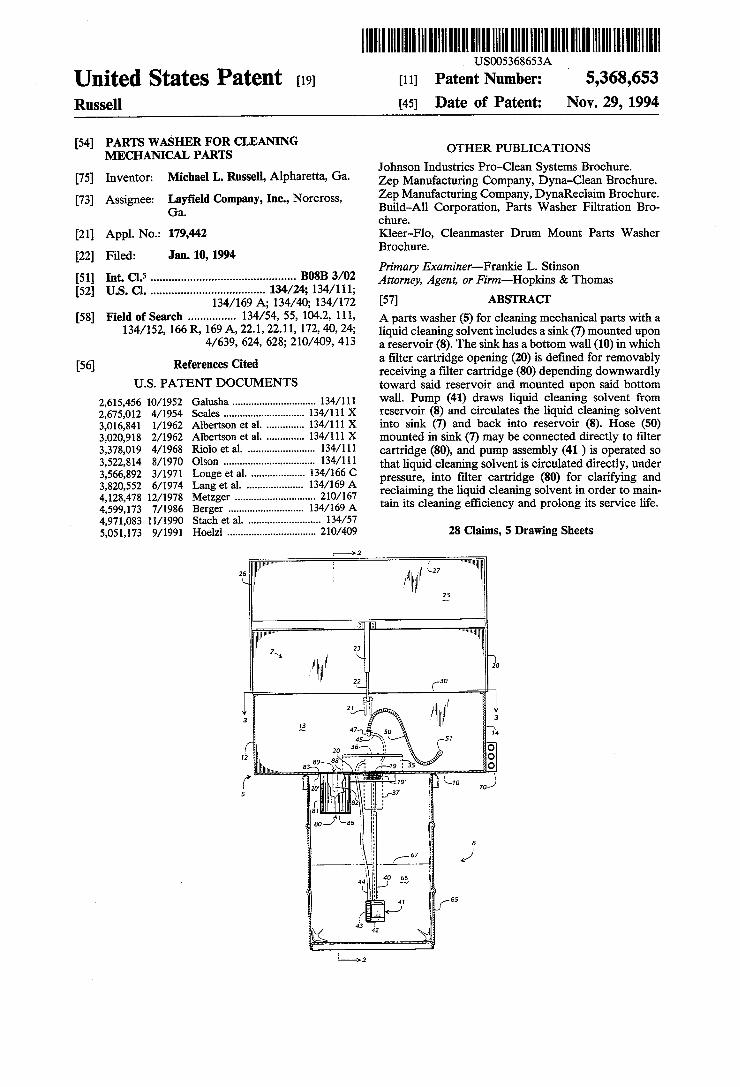
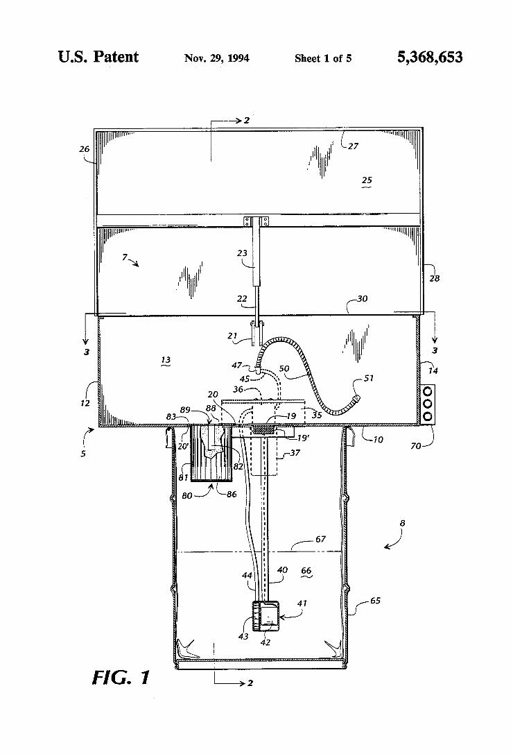
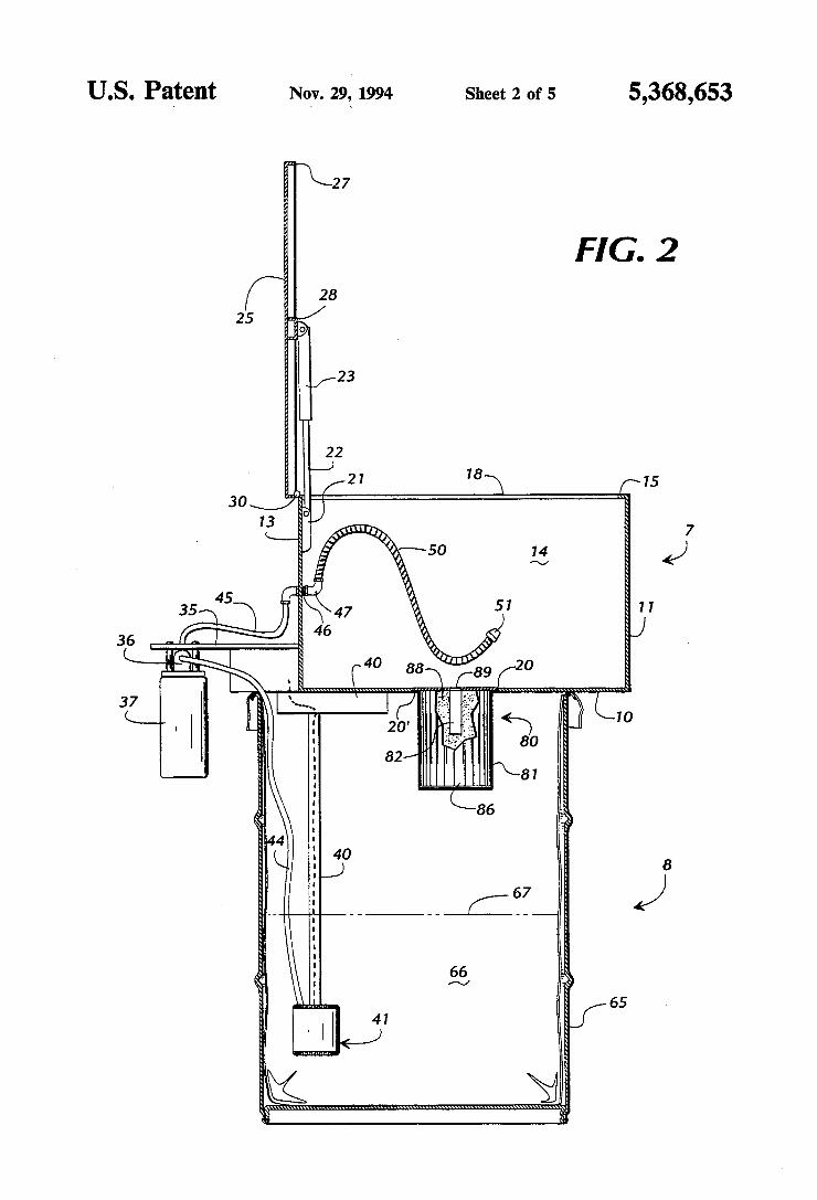
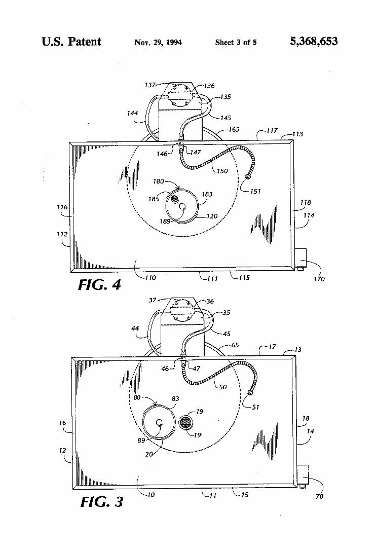
[57] ABSTRACT A parts washer (5) for cleaning mechanical parts with a liquid cleaning solvent includes a sink (7) mounted upon a reservoir (8). The sink has a bottom wall (10) in which a ?lter cartridge opening (20) is de?ned for removably receiving a ?lter cartridge (80) depending downwardly toward said reservoir and mounted upon said bottom wall. Pump (41) draws liquid cleaning solvent from reservoir (8) and circulates the liquid cleaning solvent into sink (7) and back into reservoir (8). Hose (50) mounted in sink (7) may be connected directly to ?lter cartridge (80), and pump assembly (41 ) is operated so that liquid cleaning solvent is circulated directly, under pressure, into ?lter cartridge (80) for clarifying and reclaiming the liquid cleaning solvent in order to main tain its cleaning ef?ciency and prolong its service life.
28 Claims, 5 Drawing Sheets
4,128,478 12/1978 Metzger . 4,599,173 7/1986 Berger ...... .. 134/169 A 4,971,083 11/1990 Stach et a1. . .. 134/57 5,051,173 9/1991 Hoelzl ............................... .. 210/409
2'3 """ """W"
US. Patent Nov. 29‘, 1994 Sheet 1 of 5 5,368,653
26
12
65
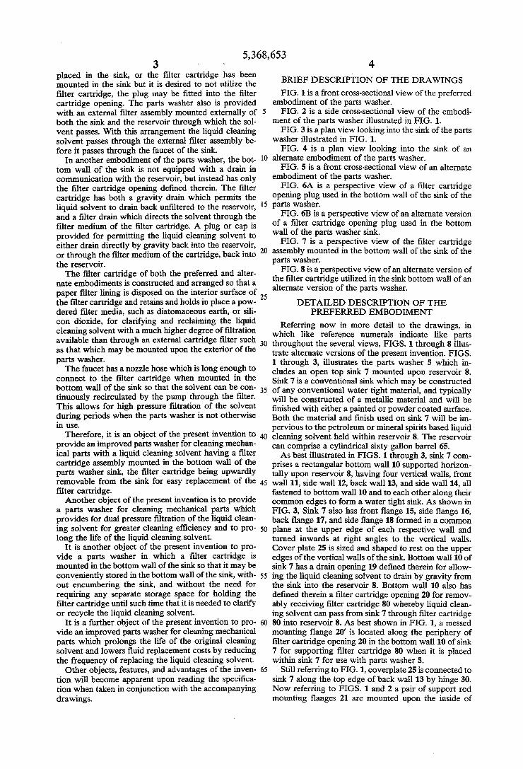
FIG. 1
US. Patent Nqv. 29? 1994 Sheet 3 of 5 5,368,653
144
116
112
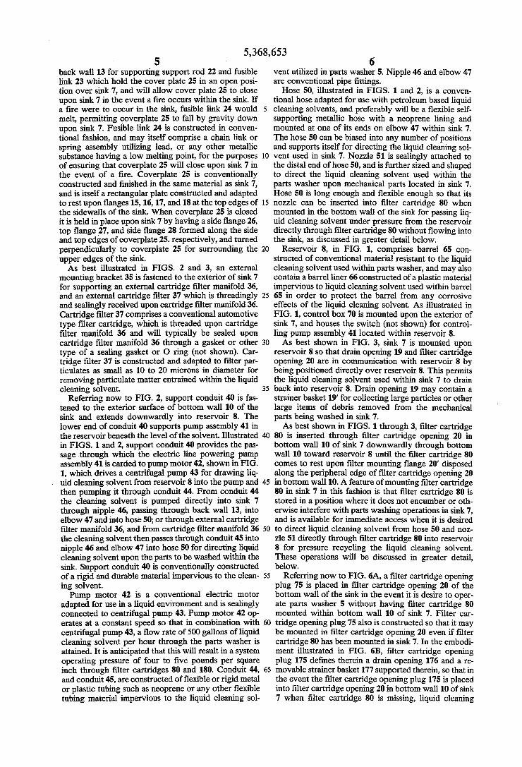
“mull||||m.......... / “W FIG.4 \ Y W W *
Hmuuww
'1 \"lmm...".......... ( ' .‘ FIG. 3 \m k” k“ 7°
Sheet 4 of 5 5,368,653 Nov. 29, 1994 US. Patent
US. Patent ’ Nqv. 29," 1994 Sheet 5 of 5 5,368,653
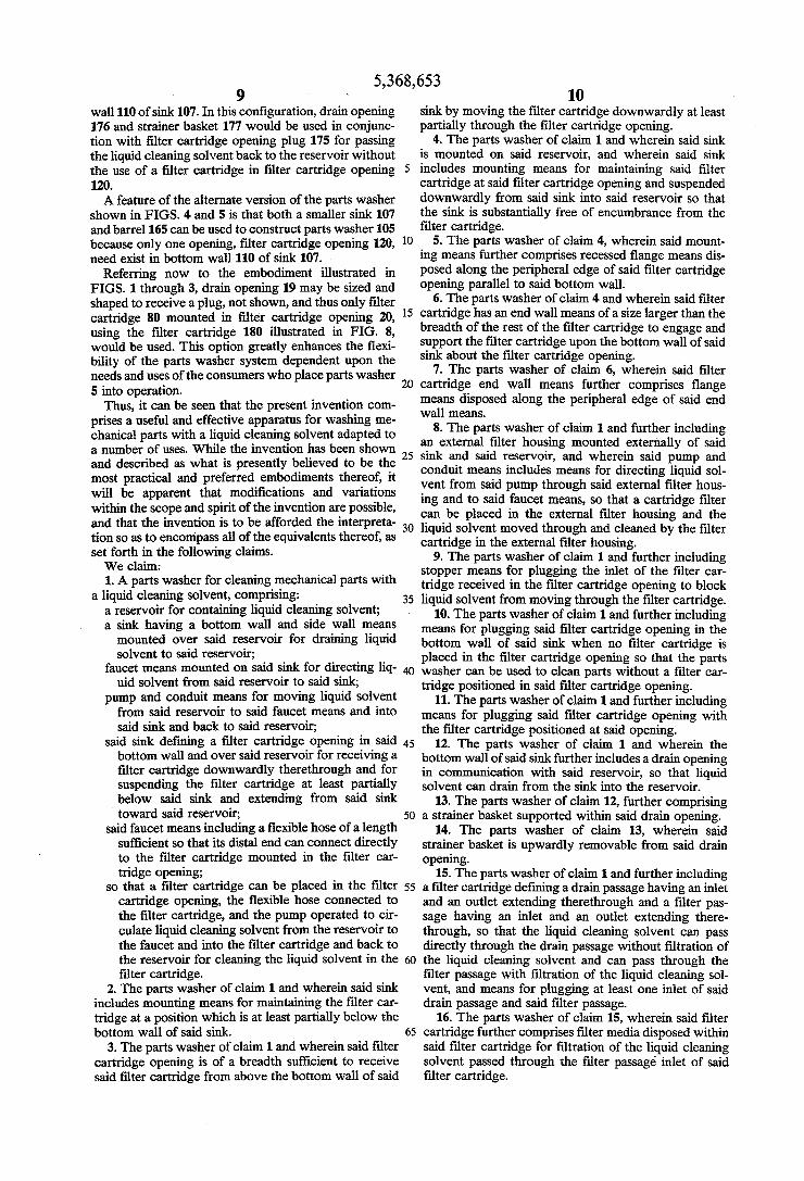
75
FIG. 6A
5,368,653 1
PARTS WASHER FOR CLEANING MECHANICAL PARTS
FIELD OF THE INVENTION
This invention relates to parts washers of the type having a sink for cleaning mechanical parts with a cleaning solvent. The cleaning solvent is circulated from a lower collection tank through a nozzle and ?ows freely from the nozzle into the sink as a worker rinses the parts with the cleaning solvent. The solvent drains from the sink back into the lower collection tank.
BACKGROUND OF THE INVENTION
The typical prior art parts washers are used to re move dirt, grime, etc. from the mechanical parts and comprise a sink mounted over a collection tank and a pump and conduit system to circulate the cleaning sol vent from the collection tank to the nozzle of the sink. The worker cleans the parts in the sink and the cleaning liquid drains from the sink into the collection tank. Over time, the liquid cleaning solvent used to remove
dirt, grit and grease from the parts being washed will become saturated with the dirt removed from the me chanical parts and the cleaning solvent loses its effec tiveness. Filters have been placed in parts washers to receive the dirty cleaning solvent draining from the sink under gravity pressure prior to passing into the collec tion reservoir. Also, ?lters have been placed in the conduit between the pump and the faucet. U. S. Pat. No. 3,378,019 to C. R. Riolo, et al. discloses a parts washer having a cylindrical ?lter cartridge mounted inside its reservoir below the sink, and the sink is re movably mounted over the reservoir. The solvent moves through the gravity drain opening of the sink and through the ?lter before it returns to the reservoir. Similarly, U. S. Pat. No. 3,522,814 to Olson discloses a parts washer having a pump for moving cleaning sol vent from a reservoir through a faucet which directs cleaning solvent into a sink and upon the parts to be washed, whereupon the cleaning solvent then drains by gravity through the bottom of the sink into a lower catch basin. A ?lter body containing waste cotton or a similar material filters the liquid cleaning solvent before it returns back to the reservoir. US. Pat. No. 4,128,478 to Metzger discloses a cylin
drical ?lter assembly in a parts washer cleaning cabinet. Metzger teaches the liquid cleaning solvent being drawn from the reservoir and passed through a car tridge ?lter prior to passing through a faucet to the sink.
All of the prior art devices cited above represent earlier attempts to deal with the problem of effectively cleaning the liquid cleaning solvent used in mechanical parts washers, in an attempt to improve the perfor mance and increase the life of the cleaning solvent. There are, however, inherent drawbacks in the known prior art. For example, in both Riolo and Metzger, the ?lter cartridge assembly is located within the reservoir. Both require substantial disassembly of the sink from the reservoir in order to replace or clean the ?lter. Also, both of these ?lter cartridges are gravity ?lters, and do not receive cleaning solvent from the sink under pres sure greater than atmospheric to permit high pressure ?ltration. Olson does not teach the use of a ?lter car tridge assembly, only a mass of ?lter material, such as cotton, disposed in a ?lter body.
Lastly, both Riolo and Metzger teach a parts washer in which the reservoir is located within a cabinet which
15
20
25
30
40
45
50
55
60
65
2 supports a sink, and the sink must be removed from the cabinet in order to gain access to and remove and re place the ?lter cartridge. Olson presents a simpler solu tion to this problem in providing a sink and ?lter body which are mounted on a reservoir barrel, but Olson does not provide a ?lter cartridge for cleaning the liquid cleaning solvent. None of the known prior art parts washers disclose a
mechanical parts washer for cleaning mechanical parts and providing an easily removable ?lter cartridge for ?ltering the liquid draining from the sink as well as a means for occasionally directing the liquid cleaning solvent under greater than atmospheric pressure through the ?lter cartridge to clarify and prolong the life of the cleaning solvent.
SUMMARY OF THE INVENTION
Brie?y described, the present invention comprises an apparatus for cleaning dirt, oil, grit, grease, and carbon from mechanical parts with a liquid cleaning solvent pumped under pressure from a reservoir through a conduit and a faucet and upon the parts to be washed in the sink, the liquid cleaning solvent then passing either through a drain in the sink directly back into the reser voir, or through a ?lter cartridge mounted in the bot tom wall of the parts washer sink, either under gravity or under greater than atmospheric pressure, and then back to the reservoir. The parts washer comprises a reservoir for contain
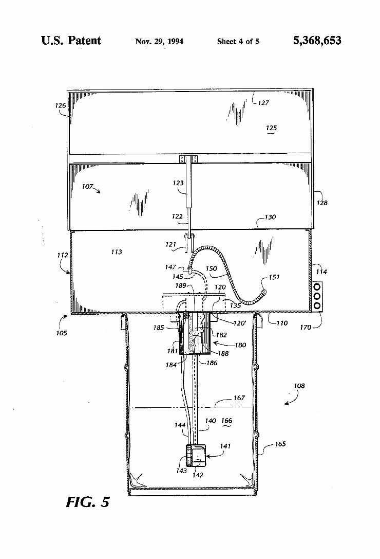
ing liquid cleaning solvent and a sink having a bottom wall and side walls mounted over the reservoir and in communication with the reservoir so that the liquid cleaning solvent drains into the reservoir. A pump and conduit means circulate the solvent from the reservoir to a faucet mounted on the sink for directing the solvent upon parts to be washed in the sink and then back to the reservoir. The bottom sink wall of the parts washer de?nes an opening over the reservoir for receiving a ?lter cartridge. The ?lter cartridge is installed by being moved downwardly through the ?lter cartridge open ing and is suspended at least partially below said sink and extends from the sink downwardly toward the reservoir. When the pump is operated to circulate the liquid cleaning solvent from the reservoir to the faucet and to the sink and then back to the reservoir, the ?lter cartridge will not encumber the sink. Yet, when the ?lter cartridge requires inspection and/or replacement, it is directly accessible without requiring disassembly of the sink from over the reservoir. The preferred embodiment of the parts washer has a
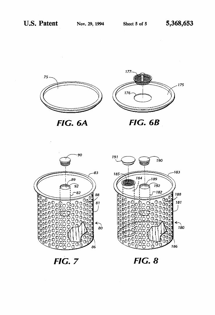
recessed ?ange located in the bottom wall of the sink about the periphery of the ?lter cartridge opening de ?ned in the sink’s bottom wall. The ?lter cartridge is removably received in the ?lter cartridge opening by inserting the ?lter cartridge from above the bottom wall of the sink and then downward into said ?lter cartridge opening toward the reservoir. The ?lter cartridge is constructed with an enlarged end adapted to be re ceived upon the recessed ?ange in the bottom of the sink, which suspends the ?lter cartridge from the bot tom wall of the sink, over and above the reservoir. By mounting the ?lter cartridge in the sink in this manner, the working space of the sink is substantially free of any encumbrance from the ?lter cartridge. The parts washer may contain a plug or cap piece for
placement in the ?lter cartridge opening of the bottom wall of the sink. If the ?lter cartridge has not been