passivating the sulfur vacancy in monolayer mos2
TRANSCRIPT

Passivating the sulfur vacancy in monolayer MoS2Haichang Lu, Andrew Kummel, and John Robertson
Citation: APL Materials 6, 066104 (2018); doi: 10.1063/1.5030737View online: https://doi.org/10.1063/1.5030737View Table of Contents: http://aip.scitation.org/toc/apm/6/6Published by the American Institute of Physics
Articles you may be interested inAccelerated carrier recombination by grain boundary/edge defects in MBE grown transition metaldichalcogenidesAPL Materials 6, 056103 (2018); 10.1063/1.5022339
Conformal coating of amorphous silicon and germanium by high pressure chemical vapor deposition forphotovoltaic fabricsAPL Materials 6, 046105 (2018); 10.1063/1.5020814
Band edge states, intrinsic defects, and dopants in monolayer HfS2 and SnS2Applied Physics Letters 112, 062105 (2018); 10.1063/1.5008959
Defect phase diagram for doping of Ga2O3APL Materials 6, 046103 (2018); 10.1063/1.5019938
Covalent nitrogen doping in molecular beam epitaxy-grown and bulk WSe2APL Materials 6, 026603 (2018); 10.1063/1.5002132
Relation between film thickness and surface doping of MoS2 based field effect transistorsAPL Materials 6, 058301 (2018); 10.1063/1.4996425
APL MATERIALS 6, 066104 (2018)
Passivating the sulfur vacancy in monolayer MoS2Haichang Lu,1 Andrew Kummel,2 and John Robertson1,a1Department of Engineering, Cambridge University, Cambridge CB2 1PZ, United Kingdom2Department of Chemistry and Biochemistry, UC, San Diego, California 92093, USA
(Received 25 March 2018; accepted 30 May 2018; published online 12 June 2018)
Various methods to passivate the sulfur vacancy in 2D MoS2 are modeled using den-sity functional theory (DFT) to understand the passivation mechanism at an atomicscale. First, the organic super acid, bis(trifluoromethane)sulfonimide (TFSI) is a strongprotonating agent, and it is experimentally found to greatly increase the photolumines-cence efficiency. DFT simulations find that the effectiveness of passivation dependscritically on the charge state and number of hydrogens donated by TFSI since thisdetermines the symmetry of the defect complex. A symmetrical complex is formedby three hydrogen atoms bonding to the defect in a −1 charge state, and this givesno bandgap states and a Fermi level in the midgap. However, a charge state of +1gives a lower symmetry complex with one state in the gap. One or two hydrogensalso give complexes with gap states. Second, passivation by O2 can provide partialpassivation by forming a bridge bond across the S vacancy, but it leaves a defectstate in the lower bandgap. On the other hand, substitutional additions do not shiftthe vacancy states out of the gap. © 2018 Author(s). All article content, except whereotherwise noted, is licensed under a Creative Commons Attribution (CC BY) license(http://creativecommons.org/licenses/by/4.0/). https://doi.org/10.1063/1.5030737
2D semiconductors such as the transition metal dichalcogenides (TMDs) have attracted con-siderable attention as opto-electronic devices because of their direct bandgap in their monolayerform1–3 and as alternatives to Si and III-Vs in field effect transistors (FETs) because their thin layersallow excellent electrostatic control of their channels, and so their FETs give good short channelperformance.4,5 Their wide range of bandgaps and band offsets give them the potential for use astunnel field effect transistors.6,7 Their interlayer van der Waals bonding means that the pristine sys-tems in principle have no dangling bonds. However, a large concentration of defects (∼1013 cm−3),thought to be sulfur vacancies, is seen in transmission electron microscopy and scanning tunnelingmicroscopy (STM) on exfoliated samples,8,9 and many like-atom bonds exist at the grain bound-aries in samples grown by chemical vapor deposition (CVD).10,11 Both types of defects will giverise to gap states and will reduce the device performance. For example, sulfur vacancies are seento reduce the photoluminescence efficiencies by typically 104,12 while their field-effect mobility indevices is well below their phonon limited mobility13 due to both high contact resistances14 anddefects.
In 3D semiconductors, there are strategies available to passivate defects. In MoS2, ways topassivate defects have been tried with varying success, but there is presently no general understandingof how best to achieve this. The most successful passivation process so far has been treating the sampleby an organic superacid bis(trifluoromethane) sulfonamide (TFSI).12 In this paper, we study variouspossible passivation schemes for TMDs and explain why they are more complicated than for simplercovalent semiconductors like Si.
Several passivation schemes for MoS2 have been reported. (1) MoS2 defect states can be removedby charge transfer doping via the van der Waals bonding of an organic monolayer, titanyl phthalo-cyanine (TiOPC).15 (2) Thiol-based molecules can reduce the sulfur vacancy density on MoS2 and
aAuthor to whom correspondence should be addressed: [email protected]
2166-532X/2018/6(6)/066104/9 6, 066104-1 © Author(s) 2018

066104-2 Lu, Kummel, and Robertson APL Mater. 6, 066104 (2018)
achieve a high mobility of 80 cm2/(V s) by a series of sulfurization reactions.16,17 Chemisorbed thiolgroups can also achieve p-type or n-type doping by choosing different functional groups.18,19 (3)Molecular oxygen can passivate MoS2 via chemisorption at the sulfur vacancy site.20 This removessome vacancy gap states21 and allows the photoluminescence (PL) efficiency to recover.22 (4) Mono-layer MoS2 can be treated with the organic super acid TFSI. This improves the PL quantum yieldand efficiency.12,23–25
Passivation can be defined as a process removing all defect states from the gap while allowing theFermi energy EF to return to the midgap. There are two standard methods to passivate defects in 3Dsemiconductors. (1) Use a chemical reactant which bonds strongly with the defect so that the resultingelectronic states now lie outside the gap.26–28 (2) Shift the defect states away from the relevant energyrange.29–31 Examples of the first method are the passivation of the residual Si dangling bonds at theSi/SiO2 interface by hydrogen, where the resulting Si−−H bonding and antibonding states lie in thevalence band (VB) and conduction band (CB) respectively.27 Examples of the second method areadding InP capping layers to the active InGaAs channel layer, where the surface states of the InPlayers lie outside the energy range of the InGaAs bandgap, while the original InGaAs gap states nowform bulk bonds with states outside its bandgap.30,31
We now use a series of defect supercell calculations to investigate possible defect reactions.The atomic geometries and electronic properties of three passivation schemes are calculated usingthe density functional theory (DFT) plane-wave CASTEP code.32,33 Ultra-soft pseudopotentials witha plane-wave cut-off energy of 320 eV are used. The Perdew-Burke-Ernzerhof (PBE) form of thegeneralized gradient approximation (GGA) is used as the electron exchange-correlation functional.The GGA treatment of the van der Waals interaction is corrected using the Grimme scheme.34
Geometry relaxation is performed until the residue force is lower than 0.03 eV/Å. A convergence testfinds that a 4 × 4 × 1 supercell with a vacuum gap of 30 Å and a 3 × 3 × 1 k-point mesh describe wellthe 2D system with a single sulfur vacancy. To overcome the error caused by the periodical mirrorcharge, a self-consistent dipole correction is implemented. Spin-polarization is used for molecularoxygen. Although molecular oxygen is a spin triplet, when it bonds onto the sulfur vacancy it becomesa singlet state.
The defect formation energies are calculated using the supercell method. Corrections for defectcharges and band occupations are applied as in the Lany and Zunger scheme.35 The total energy ofthe perfect host supercell (EH ) and the supercell with defect (Eq) are calculated for different chargestates. The defect formation energy Hq is then found from
Hq(EF , µ)= [Eq − EH ] + q(EV + ∆EF) +∑α
nα(µ0α + ∆µα), (1)
where q is the charge on the system and Eq is the energy of charged system with a defect. EH is theenergy of the charged defect-free system, EV is the valence band maximum (VBM), and ∆EF is theFermi level with the respect to VBM. nα is the number of atoms of species α, and µα is the relativechemical potential of the element α.
The equilibrium lattice parameter of 2D MoS2 is calculated in GGA to be 3.17 Å, a 0.7% errorcompared to the experimental value.36 The calculated GGA bandgap is 1.72 eV compared to anexperimental optical bandgap of 1.80 eV1 and a calculated bandgap of 1.88 eV in screened exchange(sX).37 Thus, GGA gives less bandgap error for MoS2 than for other layered chalcogenides like HfS2
or InSe.38
For the defects, TFSI is known to greatly improve the PL efficiency.12 It is dissolved in anorganic alkane forming the TFSI anion and a nearly-free proton which can hop from anion to anion.39
The TFSI anion is physisorbed near the S vacancy. It only forms a weak van der Waals bond, so itdoes not passivate directly.12 However, TFSI is a strong protonating agent with a large Hammettnumber (HO). Its proton (H+) is assumed to be the passivating agent. Figure 1 shows protons leavingthe TFSI anion and approaching the S vacancy. The vacancy complex with protons can trap electronsif necessary to form a local closed-shell system.
To understand the adsorption configuration, proton passivation is modeled as a function of itscharge state. Unlike in Si, the bonding in MoS2 is multi-centered. One Mo dangling bond contributesonly 2/3 of an electron to a Mo-S bond, rather than one electron as in a Si-Si bond. The vacancy

066104-3 Lu, Kummel, and Robertson APL Mater. 6, 066104 (2018)
FIG. 1. TFSI passivation schematic. The super-acid is a strong protonating agent where the protons can move freely to thevacancy site and interact with Mo dangling bonds. In the figure, three Hs are adsorbed onto the S vacancy where additionalelectrons can be trapped. The vacancy is at the centre of the red circle.
site has trigonal C3v symmetry, where three Mo dangling bonds form one resonant a1 state and twodegenerate e states around the gap, Figs. 2(a) and 2(b).37,40
To clean up the gap states, the symmetry should be conserved. Any half-filling of the e statesbreaks their spin degeneracy. Therefore, the adsorption configuration should be closed-shell withtrigonal symmetry, which needs three hydrogens. DFT modeling shows that the 3-H complex caneither relax into symmetrical or asymmetrical site, depending on the electron occupation of the
FIG. 2. Simple S vacancy (top) and passivation by 3 hydrogens in the +1 state. (a) Defect orbitals and (b) density of statesof the a1 and e gap states of the isolated S vacancy. (c) Asymmetric C2v configuration for 3 protons at the vacancy with twoelectrons. Orbitals of the various localized states. The S vacancy lies at the centre of red circle. (d) PDOS showing the energiesof the localized states.

066104-4 Lu, Kummel, and Robertson APL Mater. 6, 066104 (2018)
complex. The +1 (2e) and −1 (4e) charged systems were considered by adding either 2 or 4 electronsto the system of defect with three protons.
The +1 charged system is found to relax into an asymmetric C2v configuration. Here, two hydro-gens stay in the defect centre, while the third hydrogen moves away to an asymmetric off-center siteover a Mo atom, see Fig. 2(c). The first two H’s form a filled b1 bonding state with two of the Modangling bonds, Fig. 2(d). Its empty anti-bonding partner b1
∗ lies in the gap just below the conductionband minimum (CBM). The second e state forms an empty b2 state in the midgap, localized mainlyon the Mo dangling bonds.
The a1 state of the vacancy interacts with the symmetric combination of the three hydrogensto form the a1σ and a1σ
∗ states at −6.3 eV and 5.5 eV, respectively, well away from the bandgap,Figs. 2(d) and 3(a). The asymmetric hydrogen interacts with two sulfur atoms to form the a2σ and a2σ
∗
states at −7.4 eV and 5.4 eV, respectively, also well away from the bandgap. The orbital character tothe a2σ state is also seen in the partial density of states (PDOS) in Fig. 2(d). The asymmetric geometryof the +1 geometry is driven by the need to keep an empty b2 state.
There is no passivation in the +1 configuration because of its lower symmetry. The off-centerhydrogen atom means that the b1 − b1
∗ splitting is too small to move these states out of the bandgap,and the low symmetry and lack of interaction with hydrogens mean that the b2 state also remains inthe midgap.
To passivate all the e symmetry derived states, two more electrons should be added, giving a −1charge (4e). Figures 4(a)–4(f) shows the energetically favorable configuration, with three identicalhydrogens and C3v symmetry. The hydrogen orbitals form states of a1 and e symmetry, each of whichinteract with Mo dangling bond orbital combinations of the same symmetry, to form bonding statesand anti-bonding states. The resulting a1σ states lie deep in the valence band at −6.30 eV, and theiranti-bonding partner a1σ
∗ lies well above the conduction band minimum (CBM) at 5.50 eV, Figs. 3(d)and 4(b). Both of these orbitals extend along three local Mo-H bonds, Fig. 4(a). The e states also formbonding and anti-bonding states, e and e∗. The splitting of the e and e∗ states is now much larger thanin the +1 case, and both states lie within the bands and outside the gap, as can be seen comparingFigs. 3(a) and 3(b).
Figure 4(g) shows the PDOS of the −1 state. This configuration repairs the S vacancy in MoS2
and preserves the direct bandgap of 1.72 eV of perfect 2D MoS2. The highest occupied molecularorbital (HOMO) is a delocalized Mo state, derived from pure MoS2. The e state is a local resonantstate. Both of them lie below the HOMO. Therefore, all gap states are removed and EF lies at themidgap, and the 3H/4e passivation scheme is successful. The higher symmetry of this site has causeda larger bonding-antibonding splitting of the states to remove all the gap states.
FIG. 3. Molecular orbital diagram of 3 hydrogens interacting with S vacancy states. (a) Origin of a1, a2, b1, and b2 statesfor the C2v 2 electron, +1 configuration. Some states remain in the gap. (b) Origin of the states of a1 and e symmetry statesfor the C3v 4-electron, −1 configuration. The energy levels of H atoms are in violet. The valence band is in orange, and theconduction band is green. All states are repelled from the gap in the −1 charge case because its higher symmetry causes anoverall larger Mo-H interaction.

066104-5 Lu, Kummel, and Robertson APL Mater. 6, 066104 (2018)
FIG. 4. Passivation by 3 hydrogens in −1 charge state. (b) Orbitals of localized states in 3H −1 passivated S vacancy withC3v symmetry: (a) hydrogen resonant bonding state a1σ which is below VBM, (b) hydrogen resonant anti-bonding state a1σ
∗
located high in conduction bands, (c) doubly-degenerate bonding state of hydrogen with e states. Apart from hydrogen-relatedstates, there are localized resonant states near the VBM [(d)–(f)], which are the d orbitals of the 3 adjacent Mo atoms. (g)PDOS showing various defect states.
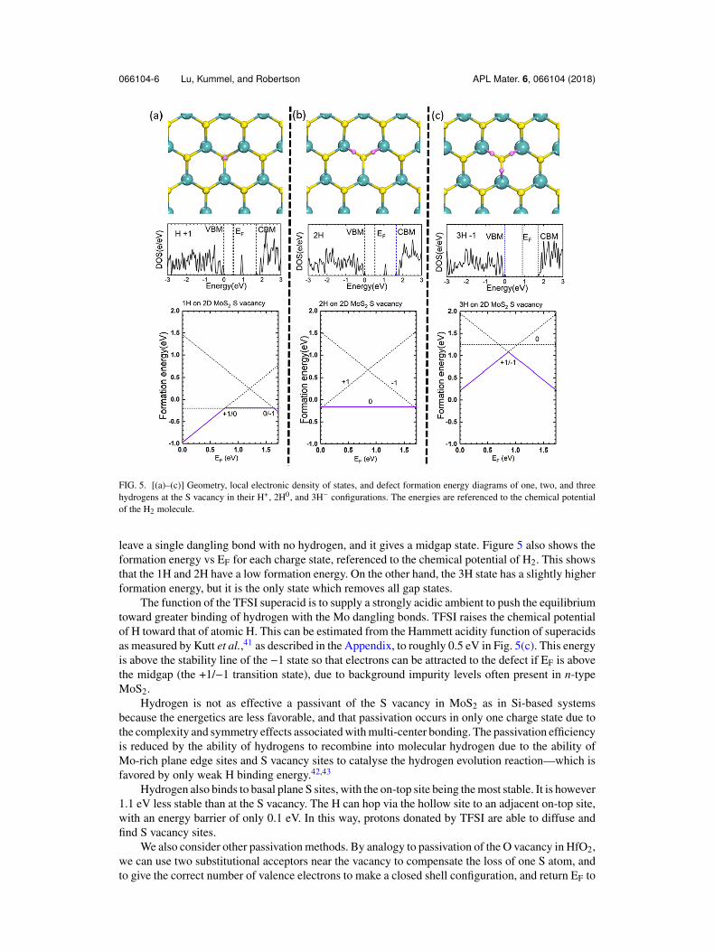
Figure 5(a) shows the geometry for the vacancy with one hydrogen and a +1 charge state. Forthe 1H case, the hydrogen lies centrally in the vacancy, and this complex gives an empty state at themidgap. For the 2H case, Fig. 5(b), the hydrogens form Mo-H bonds with the dangling bonds and
066104-6 Lu, Kummel, and Robertson APL Mater. 6, 066104 (2018)
FIG. 5. [(a)–(c)] Geometry, local electronic density of states, and defect formation energy diagrams of one, two, and threehydrogens at the S vacancy in their H+, 2H0, and 3H− configurations. The energies are referenced to the chemical potentialof the H2 molecule.
leave a single dangling bond with no hydrogen, and it gives a midgap state. Figure 5 also shows theformation energy vs EF for each charge state, referenced to the chemical potential of H2. This showsthat the 1H and 2H have a low formation energy. On the other hand, the 3H state has a slightly higherformation energy, but it is the only state which removes all gap states.
The function of the TFSI superacid is to supply a strongly acidic ambient to push the equilibriumtoward greater binding of hydrogen with the Mo dangling bonds. TFSI raises the chemical potentialof H toward that of atomic H. This can be estimated from the Hammett acidity function of superacidsas measured by Kutt et al.,41 as described in the Appendix, to roughly 0.5 eV in Fig. 5(c). This energyis above the stability line of the −1 state so that electrons can be attracted to the defect if EF is abovethe midgap (the +1/−1 transition state), due to background impurity levels often present in n-typeMoS2.
Hydrogen is not as effective a passivant of the S vacancy in MoS2 as in Si-based systemsbecause the energetics are less favorable, and that passivation occurs in only one charge state due tothe complexity and symmetry effects associated with multi-center bonding. The passivation efficiencyis reduced by the ability of hydrogens to recombine into molecular hydrogen due to the ability ofMo-rich plane edge sites and S vacancy sites to catalyse the hydrogen evolution reaction—which isfavored by only weak H binding energy.42,43
Hydrogen also binds to basal plane S sites, with the on-top site being the most stable. It is however1.1 eV less stable than at the S vacancy. The H can hop via the hollow site to an adjacent on-top site,with an energy barrier of only 0.1 eV. In this way, protons donated by TFSI are able to diffuse andfind S vacancy sites.
We also consider other passivation methods. By analogy to passivation of the O vacancy in HfO2,we can use two substitutional acceptors near the vacancy to compensate the loss of one S atom, andto give the correct number of valence electrons to make a closed shell configuration, and return EF to

066104-7 Lu, Kummel, and Robertson APL Mater. 6, 066104 (2018)
the midgap.44,45 This causes the vacancy to become V2+. This charge causes a strong ionic relaxationaround the vacancy which repels the vacancy state above the CBM and so clears the gap of defectstates. In MoS2, the process involves either replacing two Mo atoms with two Nb atoms, or replacingtwo adjacent S atoms with two As atoms, as in Figs. 6(a) and 6(b). Figure 6(a) shows the atomicconfiguration and defect orbitals of NbMo schemes. There are three different defect states, a1: theasymmetrical resonant state, b1: the d orbital of the local Mo hybrid with the Nb resonant state, andb2: the d orbital of the local Mo and Nb, Fig. 6(b). However, unlike the case of HfO2, the a1 vacancystate lies at the bottom of the gap, so EF of the modified system lies at the VB edge.
This scheme fails to passivate because the b1 and b2 defect states do not move out of the gap.Despite its formal ionic charge of Mo+4, the Mo-S bond in MoS2 is not very ionic. The Bader chargeof Mo in MoS2 is actually only +0.22. Thus there is little ionic relaxation of Mo sites toward thepositive vacancy as there was in HfO2 to move the b2 state out of the gap. Therefore, substitutionaldoping does not passivate the S vacancy.
The oxygen O2 molecule is known to passivate the S vacancy experimentally. It is thought tooccur by adding the undissociated O2 molecule across the vacancy. The isolated neutral O2 moleculeis a spin triplet with two electrons with the same spin lying in the πpx
∗ and πpy∗ states. Although the
most stable configuration of molecular O2 is open-shell, it becomes close-shell when chemisorbedonto the S vacancy. As an undissociated molecule, one atom, O1, forms two Mo−−O bonds and itssecond oxygen atom O2 forms one Mo−−O bond. The three Mo−−O bonds have the same length,2 Å, which allows O1 to lie inside the monolayer, while atom O2 stays outside the monolayer, as inthe side view in Fig. 6(a). This adsorption configuration is energetically stable after overcoming anenergy barrier at room temperature.22 The passivation occurs by compensating the S vacancy withthe two unpaired π electrons from O2. Bader charge analysis shows that charge is distributed evenlyover the three Mo’s, while O2 is more slightly electronegative than O1. Figure 6(a) shows the oxygenhybrid a1 and e states. Breaking the trigonal symmetry, the e states split up into b1 and b2 states, asshown in Fig. 6(b). The a1 state is an oxygen state near the VBM, lying just in the gap. The b1 andb2 states are in the conduction band.
FIG. 6. [(a) and (b)] Attempted passivation of S vacancy by two adjacent NbMo sites, showing orbitals and PDOS. [(c) and(d)] Passivation of S vacancy by an O2 molecule lying across the vacancy, orbitals and PDOS.

066104-8 Lu, Kummel, and Robertson APL Mater. 6, 066104 (2018)
Despite the obvious advantage of the oxygen scheme which only needs neutral oxygen, thesymmetry is broken, which means that the gap states are not sufficiently moved into the VB or CB.However, the a1 state is fully occupied by four electrons as shown, so the vacancy is not a charge trapcenter. The S vacancy may already be partially passivated during the growth of 2D MoS2 since it isexposed to air. It is possible that increasing the oxygen density or raising the temperature to help O2
over the adsorption energy barrier may achieve better passivation.Atomic oxygen will also passivate the S vacancy, being 2.1 eV more stable than adding S. Atomic
O could be produced by a plasma or ozone. However, care would need to be taken that MoS2 is notoxidized too far to an Mo oxide.
In summary, we investigated the electronic properties of S vacancy and possible passivationschemes. Three hydrogen atoms symmetrically adsorbed around the S vacancy site in its −1 chargestate successfully remove all gap states and return EF to the midgap. The passivation mechanismis more complex than of covalently bonded systems like Si and SiO2 because of the multi-centeredbonding in MoS2 and the resulting symmetry constraints that this imposes. Symmetry is criticalto moving the defect states out of gap, to avoid lifting the defect state degeneracy, and because asufficient energy splitting of bonding and anti-bonding states is needed to move states completelyout of the gap. Other methods such as substitutional doping are not as effective because, for example,the Mo−−S bond is not as ionic as HfO2.
The authors acknowledge funding from EPSRC Grant No. EP/P005152/1 and CSC. The authorsare also grateful to A. Javey for drawing attention to Ref. 41.
APPENDIX: ANALYSIS OF PROTON CHEMICAL POTENTIAL DUE TO TFSI
The Hammett acidity function (HO) allows the calculation of the ratio of the real concentrationof the base (B) and superacid (BH+) in solution if you know the pKa (called pKBH+). Normally allyou can calculate from the pKa are the activities. The activity (a) is the product of the mole fraction(x) and the activity coefficient (γ). In solutions, often aB = γBCB is used, where CB is the molarity.Once you know the HO, you can calculate the proton activity if you know the activity coefficients ofthe acid and base. In a concentrated solution, the proton activity coefficients can be far from unity,
HO = pKBH+ + log([B])/[BH+], HO =−log
(aH
+γB/γBH
+) , aB = xB · γB.
The chemical potential (µ) in an ideal solution is the chemical potential of the pure substance (µ0) plusa correction proportional to the log of the mole fraction (x). However, in a real solution the chemicalpotential is equal to the chemical potential of the pure substance plus a correction proportion to log(a).However the activity is a function of the concentration, (especially in a concentrated solution) so itmust be measured. Therefore, there is no easy way to calculate the chemical potential from HO,
µB = µB0 + RT ln(xB), µB = µB
0 + RT ln(aB).
To work around this, Kutt41 developed a method to quantify protonation strength to the solvents (DCEand MeCN) and make measurements on 66 superacids. In solutions of DCE, the TFSI (CF3SO2)2NH(denoted as HA), will partially protonate DCE denoted as S (solvent). The pKa value gives the relativeamount of protonated solvent in dilute solution,
HA + S↔A− + SH+, pKa =−log a(SH+) · a (
A−)/a(HA).
For TFSI, Ka(DCE) is −11.9, while Ka(MeCN) = 0.3; they are about 9.4 points lower than the valuesfor H2SO4 [Ka =−2.5 (DCE) and 8.7 (MeCN)], a common reference. Therefore, although one cannotcalculate the chemical potential of TFSI, one can say it is likely to raise the chemical potential of theproton donating species (SH+) by RT ln(10−pKa) which at 25 C equals ∼0.50 eV.
1 K. F. Mak, C. Lee, J. Hone, J. Shan, and T. F. Heinz, Phys. Rev. Lett. 105, 136805 (2010).2 K. F. Mak and J. Shan, Nat. Photonics 10, 216 (2016).3 D. Jariwala, V. K. Sangwan, L. J. Lauhon, T. J. Marks, and M. C. Hersam, ACS Nano 8, 1102 (2014).4 B. Radisavljevic, A. Radenovic, J. Brivio, V. Giacometti, and A. Kis, Nat. Nanotechnol. 6, 147 (2011).5 Y. Yoon, K. Ganapathi, and S. Salahuddin, Nano Lett. 11, 3786 (2011).6 D. Sarkar, X. Xie, W. Liu, W. Cao, J. Kang, Y. Gong, S. Kraemer, P. M. Ajayan, and K. Banerjee, Nature 526, 91 (2015).

066104-9 Lu, Kummel, and Robertson APL Mater. 6, 066104 (2018)
7 C. Gong, H. J. Zhang, W. H. Wang, L. Colombo, R. M. Wallace, and K. J. Cho, Appl. Phys. Lett. 103, 053513 (2013).8 W. Zhou, X. Zou, S. Najmaei, Z. Liu, Y. Shi, J. Kong, J. Lou, P. M. Ajayan, B. I. Yakobson, and J. C. Idrobo, Nano Lett.
13, 2615 (2013).9 J. Hong, Z. Hu, M. Probert, K. Li, D. Lv, X. Yang, L. Gu, N. Mao, Q. Feng, L. Xie, J. Zhang, D. Wu, Z. Zhang, C. Jin,
W. Ji, X. Zhang, J. Yuan, and Z. Zhang, Nat. Commun. 6, 6293 (2015).10 X. Zou, Y. Liu, and B. I. Yakobson, Nano Lett. 13, 253 (2013).11 S. Najmaei, Z. Liu, W. Zhou, X. L. Zou, G. Shi, S. D. Lei, B. I. Yakobson, P. M. Ajayan, and J. Lou, Nat. Mater. 12, 754
(2013).12 M. Amani, D. Lien, D. Kiriya, J. Xiao, A. Azcatl, J. Noh, S. R. Madhvapathy, R. Addou, S. Kc, M. Dubey, K. Cho,
R. M. Wallace, S. Lee, J. He, J. W. A. Iii, X. Zhang, E. Yablonovitch, and A. Javey, Science 350, 1065 (2015).13 K. Kaasbjerg, K. S. Thygesen, and K. W. Jacobsen, Phys. Rev. B 85, 115317 (2012).14 A. Allain, J. Kang, K. Banerjee, and A. Kis, Nat. Mater. 14, 1195 (2015).15 J. H. Park, A. Sanne, Y. Guo, M. Amani, K. Zhang, H. C. P. Movva, J. A. Robinson, A. Javey, J. Robertson, S. K. Banerjee,
and A. C. Kummel, Sci. Adv. 3, e1701661 (2017).16 Z. Yu, Y. Pan, Y. Shen, Z. Wang, Z.-Y. Ong, T. Xu, R. Xin, L. Pan, B. Wang, L. Sun, J. Wang, G. Zhang, Y. W. Zhang,
Y. Shi, and X. Wang, Nat. Commun. 5, 5290 (2014).17 M. Makarova, Y. Okawa, and M. Aono, J. Phys. Chem. C 116, 22411 (2012).18 K. Cho, M. Min, T. Y. Kim, H. Jeong, J. Pak, J. K. Kim, J. Jang, S. J. Yun, Y. H. Lee, W. K. Hong, and T. Lee, ACS Nano
9, 8044 (2015).19 D. M. Sim, M. Kim, S. Yim, M. J. Choi, J. Choi, S. Yoo, and Y. S. Jung, ACS Nano 9, 12115 (2015).20 H. Nan, Z. Wang, W. Wang, Z. Liang, Y. Lu, and Z. H. Ni, ACS Nano 8, 5738 (2014).21 P. K. Gogoi, Z. Hu, Q. Wang, A. Carvalho, D. Schmidt, X. Yin, Y. H. Chang, L. J. Li, C. H. Sow, A. H. C. Neto,
M. B. H. Breese, A. Rusydi, and A. T. S. Wee, Phys. Rev. Lett. 119, 077402 (2017).22 Y. Liu, P. Stradins, and S.-H. Wei, Angew. Chem., Int. Ed. 55, 965 (2016).23 M. Amani, R. A. Burke, X. Ji, P. Zhao, D. H. Lien, P. Taheri, G. H. Ahn, D. Kirya, J. W. Ager, E. Yablonovitch, J. Kong,
M. Dubey, and A. Javey, ACS Nano 10, 6535 (2016); H. Kim, D. H. Lien, M. Amani, J. W. Ager, and A. Javey, ibid. 11,5179 (2017).
24 Y. Yu, G. Li, L. Huang, A. Barrette, Y. Q. Cai, Y. Yu, K. Gundogdu, Y. W. Zhang, and L. Cao, ACS Nano 11, 9390 (2017).25 A. Alharbi, P. Zahl, and D. Shahrjerdi, Appl. Phys. Lett. 110, 033503 (2017).26 K. L. Brower and S. Myers, Appl. Phys. Lett. 57, 162 (1990).27 A. H. Edwards, Phys. Rev. B 44, 1832 (1991).28 J. H. Stathis and E. Cartier, Appl. Phys. Lett. 63, 1510 (1993).29 C. J. Sandroff, R. N. Notenburg, J. C. Bischoff, and R. Bhat, Appl. Phys. Lett. 51, 33 (1987).30 M. Radosavjevic et al., Tech Digest IEDM (IEEE, 2009), p. 13.1.31 L. Lin and J. Robertson, App. Phys. Lett. 98, 082903 (2011).32 S. J. Clark, M. D. Segall, C. J. Pickard, P. J. Hasnip, M. I. J. Probert, K. Refson, and M. C. Payne, Z. Kristallogr.–Cryst.
Mater. 220, 567 (2005).33 S. J. Clark and J. Robertson, Phys. Rev. B 82, 085208 (2010).34 S. Grimme, J. Comput. Chem. 27, 1787 (2006).35 S. Lany and A. Zunger, Phys. Rev. B 78, 235104 (2008).36 P. A. Young, J. Phys. D: Appl. Phys. 1, 936 (1968).37 D. Liu, Y. Guo, L. Fang, and J. Robertson, Appl. Phys. Lett. 103, 183113 (2013).38 H. Lu and J. Robertson, Appl. Phys. Lett. 112, 062105 (2017); Y. Guo and J. Robertson, Phys. Rev. Mater. 1, 044004 (2017).39 S. N. Suarez, J. R. P. Jayakody, S. G. Greenbaum, T. Zawodzinski, and J. J. Fontanella, J. Phys. Chem. B 114, 8941 (2010).40 J. Y. Noh, H. Kim, and Y. S. Kim, Phys. Rev. B 89, 205417 (2014).41 A. Kutt, T. Rodima, J. Saame, E. Raamat, V. Maemats, I. Kaljiurand, I. A. Koppel, R. Y. Garlyauskayte, Y. L. Yagupolskii,
L. M. Yagupolskii, E. Bernhardt, H. Willner, and I. Leite, J. Org. Chem. 76, 391 (2011).42 C. Tsai, F. Abild-Pedersen, and J. K. Nørskov, Nano. Lett. 14, 1381 (2014).43 H. Li, C. Tsai, A. L. Koh, L. Cai, A. W. Contryman, A. H. Fragapane, J. Zhao, H. S. Han, H. C. Manoharan, F. Abild-Pedersen,
J. K. Nørskov, and X. Zheng, Nat. Mater. 15, 48 (2016).44 K. Xiong, J. Robertson, and S. J. Clark, J. Appl. Phys. 99, 044105 (2006).45 D. Liu and J. Robertson, Appl. Phys. Lett. 94, 042904 (2009).