passive components for instrumentation · •describe working principle of transformer. •state...
TRANSCRIPT

PassiveComponents forInstrumentation
UNIT 1
Instrumentation Devices and Components

Outlines
• Define the terms R, L, C, X, Z
• Determine value of R, L,C in various circuits
• Compare the features of RL, RC and RLC circuits and their application as integrator and differentiator.
• Describe working principle of transformer.
• State the need for fuse, Contactor and switch
• Name the different types of Fuses, Contactors and switches

Define the terms R, L, C, X, Z

Resisters (R)

Resisters
• A resistor is an electrical component that limits or regulates the flow of electrical current in an electronic circuit.
• Resistance is the opposition that a substance offers to the flow of electric current. It is represented by the uppercase letter R.
• The standard unit of resistance is the ohm, sometimes written out as a word, and sometimes symbolized by the uppercase Greek letter omega
Series circuits
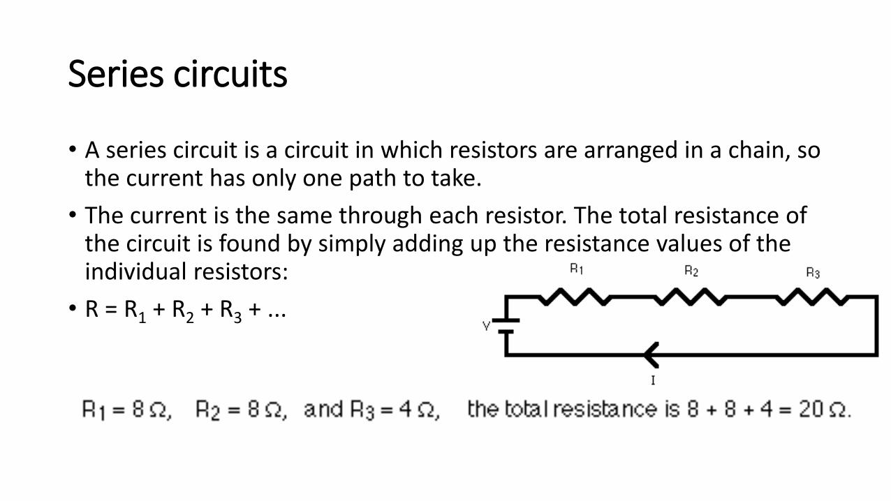
• A series circuit is a circuit in which resistors are arranged in a chain, so the current has only one path to take.
• The current is the same through each resistor. The total resistance of the circuit is found by simply adding up the resistance values of the individual resistors:
• R = R1 + R2 + R3 + ...

Parallel circuits
• A parallel circuit is a circuit in which the resistors are arranged with their heads connected together, and their tails connected together.
• The current in a parallel circuit breaks up, with some flowing along each parallel branch and re-combining when the branches meet again. The voltage across each resistor in parallel is the same.
• The total resistance of a set of resistors in parallel is found by adding up the reciprocals of the resistance values, and then taking the reciprocal of the total:
• 1 / R = 1 / R1 + 1 / R2 + 1 / R3 +...

Capacitors (C)

What is Capacitor?

What is Capacitor?
Capacitors are simple passive device that can store an
electrical charge on their plates when connected to a
voltage source

What is Capacitor?
• Starting from the outside. On the top and bottom of a capacitor you’ll find a set of metal plates, also referred to as conductors. An Electric charge finds these metal plates very attractive.
• Sitting in the middle. In the midst of these two metal plates, you’ll find an insulator or material to which electricity is not attracted. This insulator will commonly be referred to as a dielectric and can be made of paper, glass, rubber, plastic, etc.
• Connecting it together. The two metal plates on the top and bottom of a cap are connected by two electrical terminals that connect it to the rest of a circuit. One end of the capacitor connects to power, and the other flows to ground.

Capacitors in All Shapes and Sizes
• Capacitors come in a variety of shapes and sizes, all of which determine how well they can hold a charge.
• The three most common type of capacitors include the • ceramic capacitor,
• electrolytic capacitor,
• super capacitor

Ceramic Capacitors
• These are the capacitors that you’ll likely be working with on your first electronics project using a breadboard.
• Unlike their electrolytic counterparts, ceramic capacitors hold a smaller charge but also leak less current.
• They are the cheapest capacitor. You can quickly identify a ceramic capacitor by looking for the small bulbs with two terminals sticking out of them.

Electrolytic Capacitors
• These are look like the small tin cans that you’ll find on a circuit board and can hold a massive electric charge.
• They’re also the only type of capacitor that is polarized, meaning that they will only work when wired in a particular orientation.
• On these electrolytic capacitors, there’s a positive pin, called the anode, and a negative pin called the cathode.
• The anode always needs to be connected to a higher voltage.
• If you wire it up the other way around with the cathode getting a higher voltage, then prepare for an exploding cap!
• Despite being able to hold a large amount of an electric charge, electrolytic caps are also well known for leaking current quicker than ceramic caps.
• Because of this, they’re not the best cap of choice when you need to store energy.

Supercapacitors
• Supercaps are the superheroes of the capacitor family, and can store a high amount of energy!
• Unfortunately, supercaps don’t handle excess voltages very well, and blast if you exceed the maximum voltage found on a datasheet.
• Unlike electrolytic capacitors, you’ll find supercapsbeing used to store and discharge energy, much like a battery.
• But in contrast to a battery, supercaps release their charge all at once, and you’ll never get the lifespan out of one that you would from a regular battery.

Capacitor Symbols

Caps in Action – How They Work
• You’ve used a digital camera before, right? Then you know that there are a few brief moments between when you push the button to take a picture, and when the flash goes off.
• What’s happening here? There’s a capacitor attached to the flash that charges up after you press the button to snap a picture. Once that capacitor is fully charged by the camera’s battery, all of that energy explodes outward in a blinding flash of light!

Caps in Action – How They Work
• It starts with a charge. Electric current from a power source first flows into a capacitor and gets stuck on the first plate. Why does it get stuck? Because there’s an insulator that won’t let any negatively charged electronics through.
• Charges build up. As more and more electrons get stuck to this first plate, it becomes negatively charged and ends up pushing away all of the excess electrons it can’t handle to the other plate. This second plate then becomes positively charged.
• The charge is stored. As the two plates of the capacitor continue to charge, the negative and positive electrons trying to come together, but that insulator in the middle won’t let them, creating an electric field. This is why the cap continues to hold and store a charge because there’s an endless source of tension between the negative and positive sides of the two plates that aren’t resolved.
• The charge lets loose. Sooner or later the two plates in our capacitor can’t hold a charge as they’re at capacity. But what happens now? If there’s a path in your circuit for the electric charge to flow elsewhere, then all the electrons in your cap will discharge, finally ending their tension as they seek another path to each other.

Measuring That Charge
• How can you measure how much charge is stored in a capacitor?
• Every cap is made to hold a specific amount of capacitance. This is measured in Farads, after the English Chemist Michael Faraday.
• Because one Farad will hold a ton of electrical charge, you’ll typically see capacitors measured in picofarads or microfarads.
• Here’s a helpful chart that shows how these measurements break down:
Name Farads
Picofarad pF 0.000000000001 F
Nanofarad nF 0.000000001 F
Microfarad uF 0.000001 F
Milifarad mF 0.001 F
Kilofarad kF 1000 F

Measuring That Charge
• Now, to figure out how much charge a capacitor is currently storing you need this equation:
• Q = CV
• In this equation, the total charge is represented by (Q), and the relationship of that charge can be found by multiplying a capacitor’s capacitance (C), and the voltage applied to it (V).
• One thing to note here, the capacitance of a capacitor has a direct relationship to its voltage. So the more you increase or decrease the voltage source in a circuit, the more or less charge that your capacitor will have.
Name Farads
Picofarad pF 0.000000000001 F
Nanofarad nF 0.000000001 F
Microfarad uF 0.000001 F
Milifarad mF 0.001 F
Kilofarad kF 1000 F

Smoothing Current

Capacitance in Parallel Circuits

Capacitance in Series Circuits

Inductors (L)

What is Inductor
• Before we even dive into the details of an inductor, let’s first start off with something we are familiar.
• Just like a capacitor, an inductor also has the job of storing electrical energy.
• Except instead of storing energy in an electric field as a capacitor does, an inductor stores energy in a magnetic field.

Inductor and Capacitor
• Capacitors and inductors are kind of like twin brothers.
• They both do similar activities, storing energy, they just have their own unique personality and way of getting that job done.
• Where the capacitor likes to maintain a constant voltage, an inductor prefers to maintain a constant current.
• They’re both achieving the same end goal of storing and blocking the flow of energy, just in their own way.
• Unlike the complexity of a capacitor’s physical structure, inductors are a bit simpler, consisting of a simple coil of wire around a magnet, or even air. But why the coil shape?

Inductor
• But why the coil shape?• Inductors take advantage of this natural property by amplifying the size of the
magnetic field with a coiled wire. When a current is sent through the copper wire of an inductor, you get a magnetic field that is much larger, and much stronger than what you’d get in a straight path of copper.
• This is the real beauty of an inductor. By creating a magnetic field, you can convert electrical energy into magnetic energy, and store it there until it’s needed!

Inductors

Smoothing Current

Inductors
• Generally Inductor is a device which have a coil of conducting wire.• Usually wrapped around a solid core. If no core is used, then the inductor is
said to have an ‘air core’.
http://bzupages.com/f231/energy-stored-inductor-uzma-noreen-group6-part2-1464/

Symbols
http://www.allaboutcircuits.com/vol_1/chpt_15/1.html

Alternative Names for Inductors
• Reactor- inductor in a power grid
• Choke - designed to block a particular frequency while allowing currents at lower frequencies or d.c. currents through• Commonly used in RF (radio frequency) circuitry
• Coil - often coated with varnish and/or wrapped with insulating tape to provide additional insulation and secure them in place• A winding is a coil with taps (terminals).
• Solenoid – a three dimensional coil. • Also used to denote an electromagnet where the magnetic field is generated
by current flowing through a toroidal inductor.

Current and Voltage Relationships
• Unit is Henrie (H)
=
=
11t
t
LL
L
o
dtvL
i
dt
diLv

Properties of an Inductor
• Acts like an short circuit at steady state when connected to a d.c. voltage or current source.
• Current through an inductor must be continuous• There are no abrupt changes to the current, but there can be abrupt changes
in the voltage across an inductor.
• An ideal inductor does not dissipate energy, it takes power from the circuit when storing energy and returns it when discharging.

Inductors in Series

Inductors in Parallel

Reactance And Impedance
• Resistance is essentially friction against the motion of electrons.
• It is present in all conductors to some extent (except superconductors!), most notably in resistors.
• When alternating current goes through a resistance, a voltage drop is produced that is in-phase with the current.
• Resistance is mathematically symbolized by the letter “R” and is measured in the unit of ohms (Ω).

Reactance And Impedance
• Reactance is essentially inertia against the motion of electrons.
• It is present anywhere electric or magnetic fields which are developed in proportion to applied voltage or current, but most notably in capacitors and inductors.
• When alternating current goes through a pure reactance, a voltage drop is produced that is 90o out of phase with the current.
• Reactance is mathematically symbolized by the letter “X” and is measured in the unit of ohms (Ω).

Reactance And Impedance
• Impedance is a comprehensive expression of any and all forms of opposition to electron flow, including both resistance and reactance.
• It is present in all circuits, and in all components.
• When alternating current goes through an impedance, a voltage drop is produced that is somewhere between 0o and 90o out of phase with the current.
• Impedance is mathematically symbolized by the letter “Z” and is measured in the unit of ohms (Ω), in complex form.

Reactance And Impedance
• Perfect resistors possess resistance, but not reactance.
• Perfect inductors and perfect capacitors possess reactance but no resistance.
• All components possess impedance.

SummaryParameter Resistor Capacitor Inductor
Defination A resistor is an electrical component that limits or regulates the flow of electrical current in an electronic circuit.
Capacitors are simple passive device that can store an electrical charge on their plates when connected to a voltage source.
Generally Inductor is a device which have a coil of conducting wire
Representation R C L
Unit Ohm Farad Henry
Series Connection R = R1 + R2 + R3 + .. 1
𝐶=
1
𝐶1+
1
𝐶2+
1
𝐶3+⋯
L = L1 + L2 + L3 + ..
Parallel Connection
1
𝑅=
1
𝑅1+
1
𝑅2+
1
𝑅3+⋯
C = C1 + C2 + C3 + .. 1
𝐿=
1
𝐿1+
1
𝐿2+
1
𝐿3+⋯
Reactance 𝑋𝑅 = 0𝑋𝑐 =
1
2𝜋𝑓𝑐
𝑋𝐿 = 2𝜋𝑓𝐿
Impedance In phase Phase lag by 90 degree Phase lead by 90 degree

Outlines
• Define the terms R, L, C, X, Z
• Determine value of R, L,C in various circuits
• Compare the features of RL, RC and RLC circuits and their application as integrator and differentiator.
• Describe working principle of transformer.
• State the need for fuse, Contactor and switch
• Name the different types of Fuses, Contactors and switches

Compare the features of RL, RC and RLC circuits and their application as integrator and differentiator.

RC, RL and RLC SERIES CIRCUIT

RC, RL and RLC SERIES CIRCUIT
• Resistor: Resistors are denoted by the letter “R”. A resistor is an element that dissipates energy mostly in form of heat. It will have a Voltage drop across it which remains fixed for a fixed value of current flowing through it.
• Capacitor: Capacitors are denoted by the letter “C”. A capacitor is an element which stores energy (temporarily) in form of electric field. Capacitor resists changes in voltage. There are many types of capacitors, out of which the ceramic capacitor and the electrolytic capacitors are mostly used. They charge in one direction and discharge in opposite direction
• Inductor: Inductors are denoted by the letter “L”. A Inductor is also similar to capacitor, it also stores energy but is stored in form of magnetic field. Inductors resist changes current. Inductors are normally a coil wound wire and is rarely used compared to the former two components.
• When these Resistor, Capacitor and Inductors are put together we can form circuits like RC, RL and RLC circuit which exhibits time and frequency dependent responses that will e useful in many AC applications as mentioned already. A RC/RL/RLC circuit can be used as a filter, oscillator and much more.

LR Series Circuit
• An inductor in an electrical circuit opposes the flow of current through it.
• A LR Series Circuit consists basically of an inductor of inductance, L connected in series with a resistor of resistance, R.

LR Series Circuit
• The above LR series circuit is connected across a constant voltage source, (the battery) and a switch.
• Assume that the switch, S is open until it is closed at a time t = 0, and then remains permanently closed.
• The current, i begins to flow through the circuit but does not rise rapidly to its maximum value of Imax.

LR Series Circuit
• This limiting factor is due to the presence of the self induced emf within the inductor as a result of the growth of magnetic flux.
• After a time the voltage source neutralizes the effect of the self induced emf, the current flow becomes constant and the induced current and field are reduced to zero.
• We can use Kirchhoff’s Voltage Law, (KVL) to define the individual voltage drops that exist around the circuit and then use it to give us an expression for the flow of current.

LR Series Circuit
• Kirchhoff’s voltage law (KVL) gives us:
• The voltage drop across the resistor, R is I*R (Ohms Law).
• The voltage drop across the inductor, L is by now our familiar expression L(di/dt)
• Then the final expression for the individual voltage drops around the LR series circuit can be given as:
LR Series Circuit
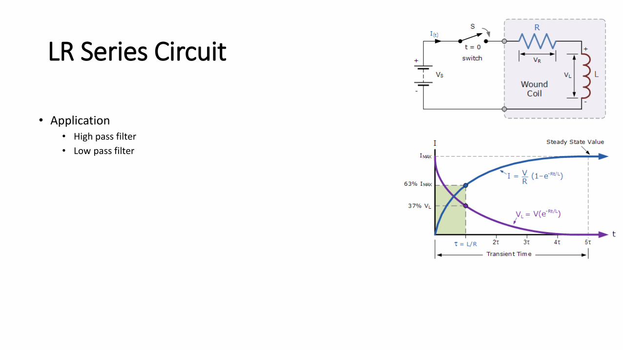
• Application• High pass filter
• Low pass filter

LR Parallel Circuit
• In RL parallel circuit resistor and inductor are connected in parallel with each other and this combination is supplied by a voltage source, Vin.
• The output voltage of circuit is Vout. Since the resistor and inductor are connected in parallel, the input voltage is equal to output voltage but the currents flowing in resistor and inductor are different.
• The parallel RL circuit is not used as filter for voltages because in this circuit, the output voltage is equal to input voltage and for this reason it is not commonly used as compared to series RL circuit.

Basic Principle of RC circuits:
• Before we start with each topic let us understand how a Resistor, Capacitor and an Inductor behave in an electronic circuit.
• For the purpose of understanding let us consider a simple circuit consisting of a capacitor and resistor in series with a power supply (5V).
• In this case when the power supply is connected to the RC pair, the voltage across the Resistor (Vr) increase to its maximum value while the voltage across the capacitor (Vc) stays at zero.
• Then slowly the capacitor starts to build charge and thus the voltage across the resistor will decrease and the voltage across the capacitor will increase until the resistor voltage (Vr) has reached Zero and Capacitor voltage (Vc) has reached its maximum value.

Basic Principle of RC circuits:

Basic Principle of RC circuits:

Basic Principle of RC circuits:
• When the switch is turned on the voltage across the resistor (red wave) reaches its maximum and the voltage across capacitor (blue wave) remains at zero.
• Then the capacitor charges up and Vr becomes zero and Vc becomes maximum.
• Similarly when the switch is turned off capacitor discharges and hence the negative voltage appears across the Resistor and as the capacitor discharges both the capacitor and resistor voltage becomes zero as shown above.
• The same can be visualized for inductors as well.
• Replace the capacitor with an inductor and the waveform will just be mirrored, that is the voltage across the resistor (Vr) will be zero when the switch is turned on since the whole voltage will appear across the Inductor (Vl).
• As the inductor charges up the voltage across (Vl) it will reach zero and the voltage across the resistor (Vr) will reach the maximum voltage.

RC Integrator
• A passive RC network is nothing more than a resistor in series with a capacitor, that is a fixed resistance in series with a capacitor.
• At low frequencies the reactance, Xc of the capacitor is high while at high frequencies its reactance is low due to the standard capacitive reactance formula of Xc = 1/(2πƒC)
• Then if the input signal is a sine wave, an rc integrator will simply act as a simple low pass filter (LPF) with a cut-off or corner frequency that corresponds to the RC time constant (tau, τ) of the series network.
• Thus the rate of charging or discharging depends on the RC time constant, τ = RC.

RC Integrator
• For an RC integrator circuit, the input signal is applied to the resistance with the output taken across the capacitor, then VOUT equals VC.
• As the capacitor is a frequency dependent element, the amount of charge that is established across the plates is equal to the time domain integral of the current.
• That is it takes a certain amount of time for the capacitor to fully charge as the capacitor can not charge instantaneously only charge exponentially.

RC Integrator
• For RC Circuit, VOUT equals VC.
• This voltage is proportional to the charge, Q being stored on the capacitor given by: Q = VxC.
• therefore:
• As i = VIN/R, substituting and rearranging to solve for VOUT as a function of time gives:

RC Differentiator
• A passive RC differentiator is nothing more than a capacitance in series with a resistance, that is a frequency dependant device which has reactance in series with a fixed resistance (the opposite to an integrator).
• Just like the integrator circuit, the output voltage depends on the circuits RC time constant and input frequency.
• If the input signal is a sine wave, an rc differentiator will simply act as a simple high pass filter (HPF) with a cut-off or corner frequency that corresponds to the RC time constant (tau, τ) of the series network.

RC Differentiator
• For an RC differentiator circuit, the input signal is applied to one side of the capacitor with the output taken across the resistor, then VOUT equals VR.
• As the capacitor is a frequency dependent element, the amount of charge that is established across the plates is equal to the time domain integral of the current.
• That is it takes a certain amount of time for the capacitor to fully charge as the capacitor can not charge instantaneously only charge exponentially.

RC Differentiator
• VOUT equals VR.
• And being a resistance, the output voltage can change instantaneously.

Series RLC Circuit
• A RLC circuit as the name implies will consist of a Resistor, Capacitor and Inductor connected in series or parallel.
• The circuit forms an Oscillator circuit which is very commonly used in Radio receivers and televisions. It is also very commonly used as damper circuits in analog applications.

Series RLC Circuit
• The RLC circuit is also called as series resonance circuit, oscillating circuit or a tuned circuit.
• These circuit has the ability to provide a resonant frequency signal as shown in the below image

Series RLC Circuit
• Here we have a capacitor C1 of 100u and an Inductor L1 of 10mH connected in series through a switch.
• Since the wire that is connecting the C and L will have some internal resistance, it is assumed that a small amount of resistance is present due to the wire.
• Initially, we keep the switch 2 as open and close the switch 1 to charge up the capacitor from the battery source (9V). Then once the capacitor is charged the switch 1 is opened and then the switch 2 is closed.
• As soon as the switch is closed the charge stored in the capacitor will move towards the inductor and charge it up. Once the capacitor is fully dis-charged, the inductor will start discharging back into the capacitor this way charges will flow to and fro between the inductor and the capacitor.
• But since there will be some loss in charges during this process total charge will gradually decrease until it reaches zero as shown in the graph above.

Series RLC Circuit
• The governing differential equation can be found by substituting into Kirchhoff's voltage law (KVL) the constitutive equation for each of the three elements. From the KVL,
• where VR, VL and VC are the voltages across R, L and C respectively and V(t) is the time-varying voltage from the source.
• Substituting into the equation above yields:

Parallel RLC Circuit
• In the above parallel RLC circuit, we can see that the supply voltage, VS is common to all three components whilst the supply current IS consists of three parts.
• The current flowing through the resistor, IR, the current flowing through the inductor, IL and the current through the capacitor, IC.
• But the current flowing through each branch and therefore each component will be different to each other and to the supply current, IS.

Parallel RLC Circuit
• Since the voltage across the circuit is common to all three circuit elements, the current through each branch can be found using Kirchoff’s Current Law, (KCL).

Series RLC Circuit
Applications:• Communication systems• Signal Processing• Voltage/Current magnification• Radio wave transmitters• RF amplifiers• Resonant LC circuit• Variable tunes circuits• Oscillator circuits• Filtering circuits

Outlines
• Define the terms R, L, C, X, Z
• Determine value of R, L,C in various circuits
• Compare the features of RL, RC and RLC circuits and their application as integrator and differentiator.
• Describe working principle of transformer.
• State the need for fuse, Contactor and switch
• Name the different types of Fuses, Contactors and switches

Describe working principle of transformer

Transformers
• A transformer is a static device which transfers electrical energy from one circuit to another through the process of electromagnetic induction.
• It is most commonly used to increase (‘step up’) or decrease (‘step down’) voltage levels between circuits.
• Working Principle of Transformer
• It works on the principle of Faraday’s Law of Electromagnetic Induction which states that “ the magnitude of voltage is directly proportional to the rate of change of flux.”

Transformers
Transformer Theory
Transformers
Transformer Theory
• Say you have one winding (also known as a coil) which is supplied by an alternating electrical source.
• The alternating current through the winding produces alternating flux that surrounds the winding.
• If another winding is brought close to this winding, some portion of this alternating flux will link with the second winding.
• As this flux is continually changing in its amplitude and direction, there must be a changing flux linkage in the second winding or coil.

Transformers
Transformer Theory
• According to Faraday’s law of electromagnetic induction, there will be an EMF induced in the second winding.
• If the circuit of this secondary winding is closed, then a current will flow through it. This is the basic working principle of a transformer.
• Let us use electrical symbols to help visualize this. The winding which receives electrical power from the source is known as the ‘primary winding’. In the diagram, this is the ‘First Coil’.
• The winding which gives the desired output voltage due to mutual induction is commonly known as the ‘secondary winding’. This is the ‘Second Coil’ in the diagram.

Transformers
Necessity of a Transformer
• Usually, electrical power is generated at 11Kv. For economical reasons AC power is transmitted at very high voltages say 220 kV or 440 kV over long distances.
• Therefore a step-up transformer is applied at the generating stations.
• Now for safety reasons the voltage is stepped down to different levels by step down transformer at various substations to feed the power to the different locations and thus the utilization of power is done at 400/230 V.

Transformers
Transformer Parts And Construction
• The three main parts of a transformer:• Primary Winding of Transformer• Magnetic Core of Transformer• Secondary Winding of Transformer
• Primary Winding of Transformer• Which produces magnetic flux when it is connected to electrical
source.
• Magnetic Core of Transformer• The magnetic flux produced by the primary winding, that will pass
through this low reluctance path linked with secondary winding and create a closed magnetic circuit.
• Secondary Winding of Transformer• The flux, produced by primary winding, passes through the core, will
link with the secondary winding. This winding also wounds on the same core and gives the desired output of the transformer.

Transformers
Types of Transformer
• Position of the windings concerning the core• Core type• Shell type
• According to the transformation ratio or number of turns in the windings• Step up• Step down
• Types of services• Power transformer• Distribution transformer• Instrument transformer
• Current transformer• Potential transformer• Auto-transformer
• On the basis of the supply• Single phase• Three phase
• On the basis of cooling• Air Natural (AN) or Self air cooled or dry type• Air ForceD (AF) or Air Blast type• Oil Natural Air Natural (ONAN)• Oil Natural Air Forced (ONAF)• Oil Forced Air Forced (OFAF)• Oil Natural Water Forced (ONWF)• Oil Forced Water Forced (OFWF)

Step-up Transformer
• A transformer in which the output (secondary) voltage is greater than its input (primary) voltage is called a step-up transformer.
• The step-up transformer decreases the output current for keeping the input and output power of the system equal.
• Considered a step-up transformer shown in the figure. The E1 and E2 are the voltages, and T1 and T2 are the number of turns on the primary and secondary winding of the transformer.
• The number of turns on the secondary of the transformer is greater than that of the primary, i.e., T2 > T1.

Step-up Transformer
• Applications• Step-up transformer is used in transmission lines for transforming the high
voltage produced by the alternator. The power loss of the transmission line is directly proportional to the square of the current flows through it.• Power = I2R
• The output current of the step-up transformer is less, and hence it is used for reducing the power loss.
• The step-up transformer is also used for starting the electrical motor, in the microwave oven, X-rays machines, etc.

Step-down Transformer
• A transformer in which the output (secondary) voltage is less than its input (primary) voltage is called a step-down transformer.
• The number of turns on the primary of the transformer is greater than the turn on the secondary of the transformer, i.e., T2 < T1. The step-down transformer is shown in the figure.
• The voltage turn ratio of the step-down transformer is 2:1. The voltage turn ratio determines the magnitude of voltage transforms from primary to secondary windings of the transformer.

Step-down Transformer
• Step-down transformer is made up of two or more coil wound on the iron core of the transformer.
• It works on the principle of magnetic induction between the coils. The voltage applied to the primary of the coil magnetize the iron core which induces the secondary windings of the transformer.
• Thus the voltage transforms from primary to the secondary winding of the transformer.
• Applications – It is used for electrical isolation, in a power distribution network, for controlling the home appliances, in a doorbell, etc.

Difference between Step-up and Step-down transformer
BASIS FOR COMPARISONSTEP-UPTRANSFORMER
STEP-DOWNTRANSFORMER
Definition Step-up transformer increase the output voltage.
Step-down transformer reduces the output voltage.
Voltage Input voltage is low while the output voltage is high.
Input voltage is high while the output voltage is low.
Winding High voltage winding is the secondary winding.
High voltage winding is the primary winding.
Current Current is low on the secondary winding. Current is high on the secondary winding.
Rating of output voltage 11000 volts or above 110v ,24v, 20v, 10v, etc.
Size of the conductor Primary winding is made up of thick insulated copper wire.
Secondary winding is made up of thick insulated copper wire
Application Power plant, X-rays machine, microwaves, etc. Doorbell, voltage converter, etc.

Autotransformer
• An autotransformer is a kind of electrical transformer where primary and secondary shares same common single winding. So basically it’s a one winding transformer.
Autotransformer Theory
• In an auto transformer, one single winding is used as primary winding as well as secondary winding.
• But in two windings transformer two different windings are used for primary and secondary purpose.
• A circuit diagram of auto transformer is shown below.

Autotransformer
• The winding AB of total turns N1 is considered as primary winding. This winding is tapped from point ′C′ and the portion BC is considered as secondary. Let’s assume the number of turns in between points ′B′ and ′C′ is N2.
• If V1voltage is applied across the winding i.e. in between ′A′ and ′C′.

Autotransformer
• Hence, the voltage across the portion BC of the winding, will be,
• As BC portion of the winding is considered as secondary, it can easily be understood that value of constant ′k′ is nothing but turns ratio or voltage ratio of that auto transformer.
• When load is connected between secondary terminals i.e.between ′B′ and ′C′, load current I2 starts flowing.
• The current in the secondary winding or common winding is the difference of I2 and I1.

Autotransformer
Advantages of using Auto Transformers
• Lighter in weight and smaller in physical size as it requires fewer windings and a smaller core.
• Less costly compared to an isolation transformer.• The advantages listed typically are for autotransformer with voltage ratio
ranging up to 3:1 voltage or vice versa. Beyond this range, an isolation transformer is usually more economical.

Autotransformer
Disadvantages of Using Auto Transformer
• There is no isolation between the primary winding and the secondary winding. Therefore protection of the equipment is dependant on the supply devices.
• As the primary and secondary share a common end, if the neutral side of the primary voltage is not grounded, the secondary side will not be either.
• A failure of the winding insulation of the autotransformer will result in full input voltage applied to the output.

Autotransformer
Applications of Auto Transformers
• Compensating voltage drops by boosting supply voltage in distribution systems.
• Auto transformers with a number of tapping are used for starting induction and synchronous motors.
• Auto transformer is used as variac in laboratory or where continuous variable over broad ranges are required.

Isolation Transformer
• Transformers are electromagnetic devices which transform alternating current (AC) electrical energy from primary to secondary side.
• The energy is transformed with equal frequency and approximately equal power by means of the transformer core magnetic field.
• Thus they provide galvanic isolation in the electrical system. • The isolation transformers operate in the same way as other transformer
types. • But the main task is to provide the galvanic isolation in the electrical
system. • They can work as step-up transformer or step-down transformers but often
operate with turns ratio 1 . This means that the primary and secondary voltage values are equal. This is obtained with an same number of turns on the primary and secondary windings.

Isolation Transformer
• The isolation transformers are used in many electrical devices as computers, measurement devices or specific industry power electronic devices.
• The main purpose of the isolation transformer is safety and protection of electronic components and the persons against electrical shock.
• It physically separates the power supplying from primary side and a secondary side circuit connected to electronic components and grounded metal parts which are in contact with the person.
• Basically, the transformer secondary side is isolated from the grounding.

Isolation Transformer
• This means that the isolation transformer secondary side must not be grounded.
• It would create a physical connection between the primary and secondary transformer side.
• The auto transformer with common winding can not be used as isolation transformer because it has a connection between primary and secondary side.
• Isolation transformer provides available supplying even if the device is broken. The primary side remains under voltage which can be used to supply some alarm or warning beep circuits when the device is broken.

Isolation Transformer
Advantages of using an isolation transformer
• The primary and secondary winding can be constructed as a step-up or step-down transformer to match the load in the electrical system
• Preventing the equipment from getting spikes and harmonics from the mains
• Safety. There will be no conductive connection between the live part of the circuit and earth. With the isolating transformer, there is no danger in touching the live while the body is earthed.
• By connecting the electrical system safety ground to the neutral conductor on the transformer secondary, it eliminates neutral-to-ground voltage and noise. This resolves reliability problems for microprocessor-based electronics.

Isolation Transformer: Applications
• The isolation transformers are used as instrument transformers when the high voltage should be measured. • The high voltage is dangerous for the person who tries to
measure high voltage but it can also harm the measurement circuits. In this case, the step-down isolation transformer is used to reduce the high voltage to the safe level and for measurement range.
• Used as Pulse transformers which transmit rectangular pulse signals and provide the electrical isolation. This type is suitable in some computer network designs.

Control Transformer
• A control transformer, (also known as an industrial control transformer, or a control power transformer, or even a machine tool transformer), is essentially an isolation transformer that provides excellent voltage regulation.
• A control transformer is very often designed to produce a high level of secondary voltage stability during brief periods of overload condition, otherwise typically known as “inrush current”.
• Most transformer products control power from higher to lower voltages.• Control transformers are generally used in an electronic circuit that
requires constant voltage or constant current with a low power or volt-amp rating.
• Various filtering devices, such as capacitors, are used to minimize the variations in the output. This results in a more constant voltage or current.

Control Transformer
• Control transformers incorporate high-quality insulating materials.
• This insulation is used to electrically insulate turn to turn windings, layer to layer windings, primary to secondary windings and ground.
Control Transformer Applications
• Control transformers are available in a variety of primary and secondary voltage combinations from 120/240 primary voltage, 24 secondary voltage at 50/60Hz through 480 primary voltage, 240 secondary voltage at 50/60Hz up to 5000 VA rating.
Typical Control Transformer applications may include:
• Hospitals Office Buildings Industrial Plants
• Schools Commercial Buildings Shopping Centers
• Apartment Buildings High Rise Buildings Institutional Buildings

Outlines
• Define the terms R, L, C, X, Z
• Determine value of R, L,C in various circuits
• Compare the features of RL, RC and RLC circuits and their application as integrator and differentiator.
• Describe working principle of transformer.
• State the need for fuse, Contactor and switch
• Name the different types of Fuses, Contactors and switches

Fuse: Wired
• In the field of electronics or electrical, a fuse is a device which gives the protection from the overcurrent.
• It comprises a strip or a metal wire that dissolves when the heavy flow of current supplies through it.
• Once this device has functioned in an open circuit, it should be rewire or changed based on the type of fuse.
• The alternative of the fuse is a stabilizer or circuit breaker, but they have many different characteristics.

Fuse: Wired
Why do we require Fuse?
• These are used to prevent the home appliances from the high current or overload damage.
• If we use a fuse in the homes, the electrical faults cannot happen in the wiring and it doesn’t damage the appliances from the fire of wire burning.
• When the fuse gets break or damage, then an abrupt sparkle happens which may direct to damage your home appliances.
• That is the reason we require different types of fuses to guard our home-appliances against damage.

Fuse: Wired
Working Principle of Fuse
• The working principle of the fuse is “heating consequence of the current”. It is fabricated with a lean strip or thread of metallic wire. The connection of the Fuse in an electrical circuit is always in series.
• When the too much current is produced due to the heavy flow of current in the electrical circuit, the fuse gets soften and it opens the circuit. The extreme flow of current may direct to the collapse of the wire and prevents the supply.
• The fuse can be changed by the new fuse with an appropriate rating. It can be designed with the elements like Cu (copper), Zn (zinc), Al (aluminum) and Ag (silver). They also perform like a circuit breaker for breaking the circuit while the abrupt fault happens in the circuit.

Fuse: Different Types of Fuses

Fuse: Different Types of Fuses

Fuse: Different Types of Fuses

Fuse: Different Types of Fuses
DC Fuses
• In a DC system, when the metallic wire Melts because of the heat generated by the over current, then Arc is produced and it is very difficult to extinct this arc because of DC constant value. So in order to minimize the fuse arcing, DC fuse are little bigger than an AC fuse which increase the distance between the electrodes to reduce the arc in the Fuse.
AC Fuses
• On the other hand, i.e. in the AC system, voltage with 60Hz or 50Hz frequency changes it amplitude from zero to 60 times every second, so arc can be extinct easily as compared to DC. Therefore, AC fuses are little bit small in sizes as compared to DC fuses.

Fuse: Different Types of Fuses
• Glass Fuses
Found primarily in automotive accessory applications

Fuse: Different Types of Fuses
Slow-Blow Fuse and a Fast-Blow Fuse
• A slow-blow fuse is defined as a fuse that can tolerate high levels of voltage for a short period without shorting itself. This means that when a short or a sudden change in voltage occurs, a slow-blow fuse doesn’t burn immediately but withstands the high current for a short time, giving you the time to do what you were going to do or time to turn off the power source.
• On the contrary, a fast-(or quick)blow fuse is a fuse that bursts instantly when high power voltage is passed through it. This fuse is the common fuse we find in much everyday electronic equipment.

Fuse: Different Types of Fuses
The Uses for a Slow-Blow Fuse and a Fast-Blow Fuse• A slow-blow fuse is normally used in the motor industry because when you
start an engine, at that moment, a high current of electricity is passed through the electronic circuit. Hence, the fuses could be blown. By using a slow-blow fuse, you bypass this problem because, as mentioned before, the slow blow fuses withstands that sudden high current flowing from the circuit, enabling the motor to start. Therefore, a slow-blow fuse is ideal in such circumstances.
• By contrast, a fast-blow fuse is used in home appliances. Home appliances are sensitive to changes in the flow of electricity. Therefore, you need a prompt reaction to counter this problem, and this is where a fast-blow fuse comes in handy. The fast-blow fuse permits the home appliance to survive by instantly shorting itself instead of the electronic circuit.

Fuse: Different Types of Fuses
The Slow-Blow Fuse vs. the Fast-Blow Fuse
• As you can see, it’s not a matter of which fuse is better than the other but rather which is fuse best for a particular situation. These two kinds of fuses have different characteristics that suit your various electronic circumstances. As mentioned previously, making sure to use the same type of fuse when replacing a faulty fuse is critical to remember.
• Another important thing to remember is that if you are unable to differentiate between the two fuses, you need to ask for professional help. Otherwise, you will damage the electronic equipment, and, even more importantly, you could get electrocuted and suffer serious injury.

Fuse: Different Types of Fuses
• Resettable fuse
• A resettable fuse is a polymeric positive temperature coefficient (PPTC) device that is a passive electronic component used to protect against overcurrent faults in electronic circuits.
• The device is also known as a multi-fuse or poly-fuse or poly-switch. They are similar in function to PTC thermistors in certain situations but operate on mechanical changes instead of charge carrier effects in semiconductors.

Fuse: Different Types of Fuses
Resettable fuse
• Operation
• A polymeric PTC device is made up of a non-conductive crystalline organic polymer matrix that is loaded with carbon black particles to make it conductive.
• While cool, the polymer is in a crystalline state, with the carbon forced into the regions between crystals, forming many conductive chains.
• Since it is conductive (the "initial resistance"), it will pass a current.
• If too much current is passed through the device the device will begin to heat. As the device heats, the polymer will expand, changing from a crystalline into an unstructured state.
• The expansion separates the carbon particles and breaks the conductive pathways, causing the device to heat faster and expand more, further raising the resistance.

Fuse: Different Types of Fuses
• When power is removed, the heating due to the leakage current will stop and the PPTC device will cool.
• As the device cools, it regains its original crystalline structure and returns to a low resistance state.
• Applications
• These devices are often used in computer power supplies and in aerospace/nuclear applications where replacement is difficult.
• Another application for such devices is protecting audio loudspeakers, particularly tweeters, from damage when over driven:

Fuse: Different Types of Fuses
• FRC: Fusible Resistors Ceramic Types (Wired Fuse)

Fuse
Applications of Different Types of Fuses
• Power Transformers
• Electrical Appliances, like ACs (Air Conditioners), TV, Washing Machines, Music Systems, and many more.
• Electrical Cabling in Home
• Mobile Phones
• Motor starters
• Laptops
• Power Chargers
• Cameras, Scanners, Printers, and Photocopiers
• Automobiles, electronic devices and Gaming’s

Outlines
• Define the terms R, L, C, X, Z
• Determine value of R, L,C in various circuits
• Compare the features of RL, RC and RLC circuits and their application as integrator and differentiator.
• Describe working principle of transformer.
• State the need for fuse, Contactor and switch
• Name the different types of Fuses, Contactors and switches

Contactors
• When a relay is used to switch a large amount of electrical power through its contacts, it is designated by a special name: contactor.
What is a Contactor?
• A contactor is an electrically controlled switch used for switching a power circuit, similar to a relay except with higher current ratings.
• A contactor is controlled by a circuit which has a much lower power level than the switched circuit. Contactors are often used for 150 Hp motor.
• Perhaps the most common industrial use for contactors is the control of electric motors.

Contactors
Magnetic contactors
• Magnetic contactor is a device or switch which operate magnetically and close or open the electric circuit.

Contactor – Construction
• Like a relay, a contactor also has• Contact• Spring• Electromagnet
• The contact part of the contactor includes the power contacts as well as the auxiliary contacts. The power contacts gains the power for the contactor and the auxiliary contacts is used to bring a loop with the rest of the rest of the devices it is attached to. These contacts are connected to the contact springs.
• The contacts are controlled by the electromagnet. Both these contacts and electromagnet are enclosed in a frame which is usually made of insulating materials.

Contactor: Working
• Mostly, they are setup with Normally Open contacts. These are devices which handle more than 20 Amperes current and over 100 Kilo Watts power.
• The contactor has an AC/DC supply driven coil input. This coil will mostly be controlled by a lower voltage PLC.
• When current is passed through the contactor, the electromagnet starts to build up a magnetic field. Thus the moving and fixed contacts make a short circuit.
• Thus the current is passed through them to the next circuit. The armature coil brings in high current in the initial position.
• When the current is stopped, the coil gets de-energized and thus the contacts get open circuited.

Contactor: 1 Phase Vs 3 Phase
• Every 3 phase contactor has 3 poles, one for each phase, while every single phase contactor has either 1 or 2 poles
• The difference in pole counts between a single phase and a 3 phase contactor has to do with the fact that there are three different AC voltage waveforms being supplied to a 3 phase motor, which requires 3 "hot" lines and 1 neutral (or ground), and there is one pole for each hot line.
• In contrast, single phase systems use voltage sources with the same AC voltage waveform, which requires only 2 hot lines and a ground.
• Whether you use a single or double pole contactor for a single phase motor is up to you, but all 3 phase contactors come with 3 poles.

Contactor: 1 Phase Vs 3 Phase
Can I use a 3 phase contactor for a single phase motor?
• Yes, but you will need to rewire the cables to make a series connection. For example, you could connect T1 on the overload relay to L2 on the 3 phase contactor (see the figure to the right).
• Also, even though a 3 phase contactor can be used for single phase motors, contactors built especially for single phase motors are cheaper.

Switches

SPDT, DPDT, 1-NO,1-NC, Iron clad, Reed, Limit

Switch
What is a Switch?
• A switch is a component which controls the open-ness or closed-ness of an electric circuit. They allow control over current flow in a circuit.
• A switch can only exist in one of two states: open or closed.
• In the off state, a switch looks like an open gap in the circuit. This, in effect, looks like an open circuit, preventing current from flowing.
• In the on state, a switch acts just like a piece of perfectly-conducting wire. A short. This closes the circuit, turning the system "on" and allowing current to flow unimpeded through the rest of the system.

Switch
Poles and Throws, Open and Closed• A switch must have at least two terminals, one for the current to
(potentially) go in, another to (potentially) come out. That only describes the simplest version of a switch though. More often than not, a switch has more than two pins. So how do all of those terminals line up with the internal workings of the switch? This is where knowing how many poles and throws a switch has is essential.
• The number of poles on a switch defines how many separate circuits the switch can control. So a switch with one pole, can only influence one single circuit. A four-pole switch can separately control four different circuits.
• A switch’s throw-count defines how many positions each of the switch’s poles can be connected to. For example, if a switch has two throws, each circuit (pole) in the switch can be connected to one of two terminals.

Switch• SPST
• A single-pole, single-throw (SPST) switch is as simple as it gets. It's got one output and one input. The switch will either be closed or completely disconnected. SPSTs are perfect for on-off switching. They’re also a very common form of momentary switches. SPST switches should only require two terminals.

Switch• SPDT
• Another common switch-type is the SPDT. SPDTs have three terminals: one common pin and two pins which vie for connection to the common. SPDTs are great for selecting between two power sources, swapping inputs, or whatever it is you do with two circuits trying to go one place. Most simple slide switches are of the SPDT variety. SPDT switches should usually have three terminals. (Sidenote: in a pinch an SPDT can actually be made into an SPST by just leaving one of the switch throws unconnected).

Switch• DPDT
• Adding another pole to the SPDT creates a double-pole, double-throw (DPDT) switch. Basically two SPDT switches, which can control two separate circuits, but are always switched together by a single actuator. DPDTs should have six terminals.

SwitchNormally Open/Closed
• When a momentary switch is not actuated, it’s in a “normal” state. Depending on how the button is constructed, its normal state can be either an open circuit or a short circuit. When a button is open until actuated, it’s said to be normally open (abbreviated NO). When you actuate an NO switch, you’re closing the circuit, which is why these are also called “push-to-make” switches.
• Conversely, if a button usually acts like a short circuit unless actuated, it’s called a normally closed (NC) switch. NC switches are “push-to-break”; actuating the switch creates an open circuit.
• Among the two types, you’re probably much more likely to encounter a normally open momentary switch.

SwitchReed Switch
• The contacts of a reed switch are closed by bringing a small magnet near the switch. They are used in security circuits, for example to check that doors are closed. Standard reed switches are SPST (simple on-off) but SPDT (changeover) versions are also available.

Switch: Double Pole Iron Clad or DPIC switch

Switch
• Limit Switch• limit switch is a switch operated by the
motion of a machine part or presence of an object.
• They are used for controlling machinery as part of a control system, as a safety interlocks, or to count objects passing a point.
• A limit switch is an electromechanical device that consists of an actuator mechanically linked to a set of contacts.
• When an object comes into contact with the actuator, the device operates the contacts to make or break an electrical connection.

What is the ability to store energy in an electric field called? (T5C01)
• A. Inductance
• B. Resistance
• C. Tolerance
• D. Capacitance

What is the ability to store energy in an electric field called? (T5C01)
• A. Inductance
• B. Resistance
• C. Tolerance
• D. Capacitance

What is the basic unit of capacitance? (T5C02)
• A. The farad
• B. The ohm
• C. The volt
• D. The henry

What is the basic unit of capacitance? (T5C02)
• A. The farad
• B. The ohm
• C. The volt
• D. The henry

What is the ability to store energy in a magnetic field called? (T5C03)
• A. Admittance
• B. Capacitance
• C. Resistance
• D. Inductance
What is the ability to store energy in a magnetic field called? (T5C03)
• A. Admittance
• B. Capacitance
• C. Resistance
• D. Inductance

What is the basic unit of inductance? (T5C04)
• A. The coulomb
• B. The farad
• C. The henry
• D. The ohm

What is the basic unit of inductance? (T5C04)
• A. The coulomb
• B. The farad
• C. The henry
• D. The ohm

What electrical component is used to oppose the flow of current in a DC circuit? (T6A01)
• A. Inductor
• B. Resistor
• C. Voltmeter
• D. Transformer

What electrical component is used to oppose the flow of current in a DC circuit? (T6A01)
• A. Inductor
• B. Resistor
• C. Voltmeter
• D. Transformer

What type of component is often used as an adjustable volume control? (T6A02)
• A. Fixed resistor
• B. Power resistor
• C. Potentiometer
• D. Transformer

What type of component is often used as an adjustable volume control? (T6A02)
• A. Fixed resistor
• B. Power resistor
• C. Potentiometer
• D. Transformer

What electrical parameter is controlled by a potentiometer? (T6A03)
• A. Inductance
• B. Resistance
• C. Capacitance
• D. Field strength

What electrical parameter is controlled by a potentiometer? (T6A03)
• A. Inductance
• B. Resistance
• C. Capacitance
• D. Field strength

What electrical component stores energy in an electric field? (T6A04)
• A. Resistor
• B. Capacitor
• C. Inductor
• D. Diode

What electrical component stores energy in an electric field? (T6A04)
• A. Resistor
• B. Capacitor
• C. Inductor
• D. Diode

What type of electrical component consists of two or more conductive surfaces separated by an insulator? (T6A05)
• A. Resistor
• B. Potentiometer
• C. Oscillator
• D. Capacitor

What type of electrical component consists of two or more conductive surfaces separated by an insulator? (T6A05)
• A. Resistor
• B. Potentiometer
• C. Oscillator
• D. Capacitor

What type of electrical component stores energy in a magnetic field? (T6A06)
• A. Resistor
• B. Capacitor
• C. Inductor
• D. Diode

What type of electrical component stores energy in a magnetic field? (T6A06)
• A. Resistor
• B. Capacitor
• C. Inductor
• D. Diode

What electrical component is usually composed of a coil of wire? (T6A07)• A. Switch
• B. Capacitor
• C. Diode
• D. Inductor

What electrical component is usually composed of a coil of wire? (T6A07)
• A. Switch
• B. Capacitor
• C. Diode
• D. Inductor

What electrical component is used to connect or disconnect electrical circuits? (T6A08)
• A. Zener diode
• B. Switch
• C. Inductor
• D. Variable resistor

What electrical component is used to connect or disconnect electrical circuits? (T6A08)
• A. Zener diode
• B. Switch
• C. Inductor
• D. Variable resistor

What electrical component is used to protect other circuit components from current overloads? (T6A09)
• A. Fuse
• B. Capacitor
• C. Shield
• D. Inductor

What electrical component is used to protect other circuit components from current overloads? (T6A09)
• A. Fuse
• B. Capacitor
• C. Shield
• D. Inductor

What class of electronic components is capable of using a voltage or current signal to control current flow? (T6B01)
• A. Capacitors
• B. Inductors
• C. Resistors
• D. Transistors
What class of electronic components is capable of using a voltage or current signal to control current flow? (T6B01)
• A. Capacitors
• B. Inductors
• C. Resistors
• D. Transistors

What electronic component allows current to flow in only one direction? (T6B02)
• A. Resistor
• B. Fuse
• C. Diode
• D. Driven element

What electronic component allows current to flow in only one direction? (T6B02)
• A. Resistor
• B. Fuse
• C. Diode
• D. Driven element

Which of these components can be used as an electronic switch or amplifier? (T6B03)
• A. Oscillator
• B. Potentiometer
• C. Transistor
• D. Voltmeter

Which of these components can be used as an electronic switch or amplifier? (T6B03)
• A. Oscillator
• B. Potentiometer
• C. Transistor
• D. Voltmeter

Which of these components is made of three layers of semiconductor material? (T6B04)
• A. Alternator
• B. Bipolar junction transistor
• C. Triode
• D. Pentagrid converter

Which of these components is made of three layers of semiconductor material? (T6B04)
• A. Alternator
• B. Bipolar junction transistor
• C. Triode
• D. Pentagrid converter

Which of the following electronic components can amplify signals? (T6B05)
• A. Transistor
• B. Variable resistor
• C. Electrolytic capacitor
• D. Multi-cell battery

Which of the following electronic components can amplify signals? (T6B05)
• A. Transistor
• B. Variable resistor
• C. Electrolytic capacitor
• D. Multi-cell battery

How is a semiconductor diode’s cathode lead usually identified? (T6B06)
• A. With the word “cathode”
• B. With a stripe
• C. With the letter “C”
• D. All of these choices are correct

How is a semiconductor diode’s cathode lead usually identified? (T6B06)
• A. With the word “cathode”
• B. With a stripe
• C. With the letter “C”
• D. All of these choices are correct

What does the abbreviation “LED” stand for? (T6B07)
• A. Low Emission Diode
• B. Light Emitting Diode
• C. Liquid Emission Detector
• D. Long Echo Delay

What does the abbreviation “LED” stand for? (T6B07)
• A. Low Emission Diode
• B. Light Emitting Diode
• C. Liquid Emission Detector
• D. Long Echo Delay

What does the abbreviation “FET” stand for? (T6B08)
• A. Field Effect Transistor
• B. Fast Electron Transistor
• C. Free Electron Transition
• D. Field Emission Thickness

What does the abbreviation “FET” stand for? (T6B08)
• A. Field Effect Transistor
• B. Fast Electron Transistor
• C. Free Electron Transition
• D. Field Emission Thickness

What are the names of the two electrodes of a diode? (T6B09)
• A. Plus and minus
• B. Source and drain
• C. Anode and cathode
• D. Gate and base

What are the names of the two electrodes of a diode? (T6B09)
• A. Plus and minus
• B. Source and drain
• C. Anode and cathode
• D. Gate and base

Which semiconductor component has an emitter electrode? (T6B10)• A. Bipolar transistor
• B. Field effect transistor
• C. Silicon diode
• D. Bridge rectifier

Which semiconductor component has an emitter electrode? (T6B10)• A. Bipolar transistor
• B. Field effect transistor
• C. Silicon diode
• D. Bridge rectifier
Which semiconductor component has a gate electrode? (T6B11)
• A. Bipolar transistor
• B. Field effect transistor
• C. Silicon diode
• D. Bridge rectifier

Which semiconductor component has a gate electrode? (T6B11)
• A. Bipolar transistor
• B. Field effect transistor
• C. Silicon diode
• D. Bridge rectifier

What is the term that describes a transistor’s ability to amplify a signal? (T6B12)
• A. Gain
• B. Forward resistance
• C. Forward voltage drop
• D. On resistance

What is the term that describes a transistor’s ability to amplify a signal? (T6B12)
• A. Gain
• B. Forward resistance
• C. Forward voltage drop
• D. On resistance

What is the name for standardized representations of components in an electrical wiring diagram? (T6C01)
• A. Electrical depictions
• B. Grey sketch
• C. Schematic symbols
• D. Component callouts

What is the name for standardized representations of components in an electrical wiring diagram? (T6C01)
• A. Electrical depictions
• B. Grey sketch
• C. Schematic symbols
• D. Component callouts

Which of the following is accurately represented in electrical circuit schematic diagrams? (T6C13)
• A. Wire lengths
• B. Physical appearance of components
• C. The way components are interconnected
• D. All of these choices are correct

Which of the following is accurately represented in electrical circuit schematic diagrams? (T6C13)
• A. Wire lengths
• B. Physical appearance of components
• C. The way components are interconnected
• D. All of these choices are correct

Which of the following devices or circuits changes an alternating current into a varying direct current signal? (T6D01)
• A. Transformer
• B. Rectifier
• C. Amplifier
• D. Reflector

Which of the following devices or circuits changes an alternating current into a varying direct current signal? (T6D01)
• A. Transformer
• B. Rectifier
• C. Amplifier
• D. Reflector

Which best describes a relay? (T6D02)
• A. A switch controlled by an electromagnet
• B. A current controlled amplifier
• C. An optical sensor
• D. A pass transistor

Which best describes a relay? (T6D02)
• A. A switch controlled by an electromagnet
• B. A current controlled amplifier
• C. An optical sensor
• D. A pass transistor
Which of the following can be used to display signal strength on a numeric scale? (T6D04)
• A. Potentiometer
• B. Transistor
• C. Meter
• D. Relay

Which of the following can be used to display signal strength on a numeric scale? (T6D04)
• A. Potentiometer
• B. Transistor
• C. Meter
• D. Relay

What component is commonly used to change 120V AC house current to a lower AC voltage for other uses? (T6D06)
• A. Variable capacitor
• B. Transformer
• C. Transistor
• D. Diode

What component is commonly used to change 120V AC house current to a lower AC voltage for other uses? (T6D06)
• A. Variable capacitor
• B. Transformer
• C. Transistor
• D. Diode

Which of the following is commonly used as a visual indicator? (T6D07)
• A. LED
• B. FET
• C. Zener diode
• D. Bipolar transistor
Which of the following is commonly used as a visual indicator? (T6D07)
• A. LED
• B. FET
• C. Zener diode
• D. Bipolar transistor

Which of the following is used together with an inductor to make a tuned circuit? (T6D08)
• A. Resistor
• B. Zener diode
• C. Potentiometer
• D. Capacitor

Which of the following is used together with an inductor to make a tuned circuit? (T6D08)
• A. Resistor
• B. Zener diode
• C. Potentiometer
• D. Capacitor

What is the name of the device that combines several semiconductors and other components into one package? (T6D09)
• A. Transducer
• B. Multi-pole relay
• C. Integrated circuit
• D. Transformer

What is the name of the device that combines several semiconductors and other components into one package? (T6D09)
• A. Transducer
• B. Multi-pole relay
• C. Integrated circuit
• D. Transformer

What is the purpose of a fuse in an electrical circuit? (T0A04)
• A. To prevent power supply ripple from damaging a circuit
• B. To interrupt power in case of overload
• C. To limit current to prevent shocks
• D. All of these choices are correct

What is the purpose of a fuse in an electrical circuit? (T0A04)
• A. To prevent power supply ripple from damaging a circuit
• B. To interrupt power in case of overload
• C. To limit current to prevent shocks
• D. All of these choices are correct

Why is it unwise to install a 20-ampere fuse in the place of a 5 ampere fuse? (T0A05)
• A. The larger fuse would be likely to blow because it is rated for higher current
• B. The power supply ripple would greatly increase
• C. Excessive current could cause a fire
• D. All of these choices are correct

Assignment 1
1. Define the term Resistance and capacitance.
2. Draw the circuit diagram of RC differentiator and Integrator.
3. Give the name of different types of contactors and switches.
4. Describe the working of step-up transformer.
5. Discuss about working of isolation transformer.
6. Define the term resistance and give its unit.
7. Define the term Impedance and give its unit.
8. If two resistors of 30 Ω value are connected in series, what will be the equivalent resistance? Also determine their equivalent resistance, when they both are connected in parallel.

Assignment 2
1. Compare the features of RL and RC circuits in brief.
2. Explain in brief about step down transformer.
3. State need for Switches. Name different types of switches.
4. Define the term Capacitance and give its unit.
5. State need for fuses. Write names of different types of fuses.
6. State need for Contactors. Write names of different types of Contactors.
7. Explain RC circuit as differentiator.
8. Explain RC circuit as integrator.

Assignment 3
1. Describe working principle of transformer in brief.
2. Define term inductance and write equation for equivalent value of series and parallel combination of inductance.
3. If 3 resistors of 150 Ω resistances are connected in series, what will be the equivalent resistance? Also find out equivalent resistance if they are connected in parallel.
4. Define the term inductance and give its unit.
5. If circuit has 2 Capacitor of 20μF are connected in series. Find out total capacitance. What is equivalent capacitance if they are connected in parallel.