passive phase-conjugate signaling using pulse … ppm.pdfpassive phase-conjugate signaling using...
TRANSCRIPT
MTS 0-933957-28-9 1
Passive Phase-Conjugate Signaling Using Pulse-Position Modulation
Paul Hursky and Michael B. Porter Science Applications International Corporation
1299 Prospect Street, Suite 305 La Jolla, CA 92037
Joseph A. Rice and Vincent K. McDonald Space and Naval Warfare Systems Center
San Diego, CA 92152
Abstract- Acoustic communications is an attractive option for networking distr ibuted assets, such as UUVs, autonomous sensors, and other systems that must talk to one another in the ocean. The ocean is often a complex multipath channel and impressive progress has been made in developing equalization algor ithms to overcome this. Unfor tunately, many of these algor ithms are computationally demanding and not as power-efficient as one would like; in many applications it is better to trade bit rate for longer operational life. For example, a wakeup function is intr insically low rate but must be low power and highly reliable. We will discuss a fundamentally different modulation scheme to address these requirements. An added benefit is that it leads to a receiver that is much less complex than an adaptive equalizer .
I. INTRODUCTION
Acoustic signaling for wireless digital communications in the undersea environment is a cost-effective alternative to both radio telemetry systems (vulnerable to weather, rough seas, and pilfering) and cabled systems (vulnerable to commercial trawling). Time-varying multipath and often harsh ambient noise conditions characterize the underwater acoustic channel. Much effort has been directed at developing channel equalizers and adaptive spatial processing techniques so that coherent phase modulation can be used to achieve the desired high bit rates (see [1] and [2]). These techniques are computationally demanding and often require sensor arrays, requirements that are not especially well suited for applications where long-life battery operation is being contemplated. We will describe a modulation technique that relies upon phase conjugation (or time reversal, in the time domain) to compensate for multipath, effectively using the environment to focus all multipath arrivals (see [3], [4], and [5]). This results in a demodulation scheme that is much simpler than an adaptive equalizer, yet one that nevertheless can cope with significant multipath spreading.
The use of passive phase conjugation for pulse compression was reported in [4], using a vertical line array receiver to exploit spatial as well as temporal focusing. We show how this concept can be extended to realize a communications system and how pulse-position modulation can be used to increase the bit rate in this context, although we use single element sources and receiver and, unlike [4], do not take advantage of aperture at the source or receiver.
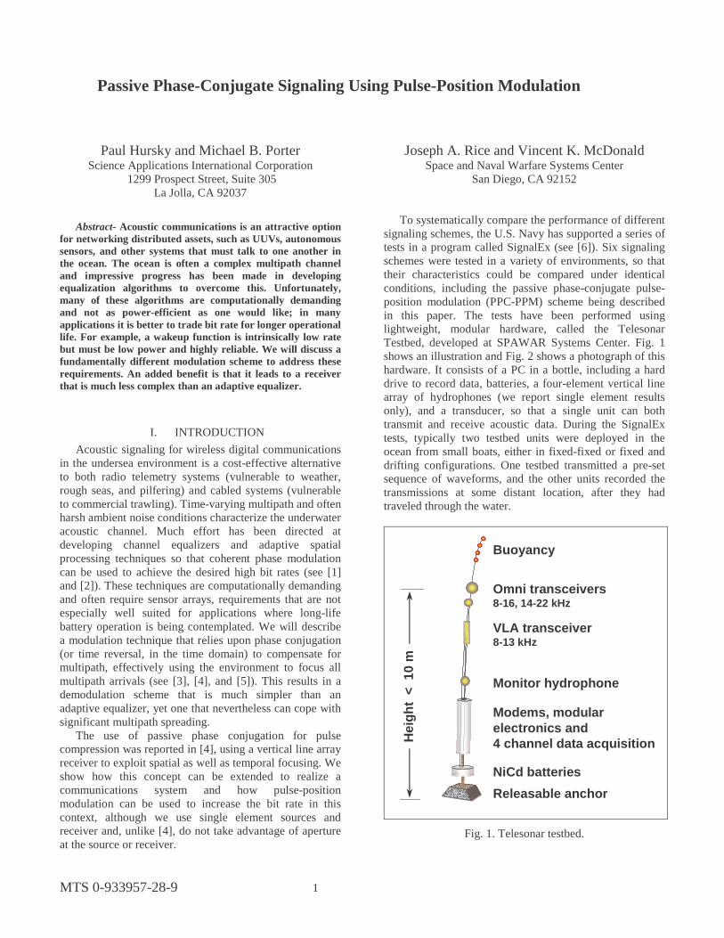
To systematically compare the performance of different signaling schemes, the U.S. Navy has supported a series of tests in a program called SignalEx (see [6]). Six signaling schemes were tested in a variety of environments, so that their characteristics could be compared under identical conditions, including the passive phase-conjugate pulse-position modulation (PPC-PPM) scheme being described in this paper. The tests have been performed using lightweight, modular hardware, called the Telesonar Testbed, developed at SPAWAR Systems Center. Fig. 1 shows an illustration and Fig. 2 shows a photograph of this hardware. It consists of a PC in a bottle, including a hard drive to record data, batteries, a four-element vertical line array of hydrophones (we report single element results only), and a transducer, so that a single unit can both transmit and receive acoustic data. During the SignalEx tests, typically two testbed units were deployed in the ocean from small boats, either in fixed-fixed or fixed and drifting configurations. One testbed transmitted a pre-set sequence of waveforms, and the other units recorded the transmissions at some distant location, after they had traveled through the water.
Modems, modularelectronics and4 channel data acquisition
Omni transceivers8-16, 14-22 kHz
NiCd batteries
Buoyancy
VLA transceiver8-13 kHz
Monitor hydrophone
Releasable anchor
Hei
gh
t <
10
m
Fig. 1. Telesonar testbed.

2
Mk-1Mk-1
Mk-2, 2000-01Mk-2, 2000-01
Fig. 2 Telesonar testbed hardware.
Telesonar testbeds were deployed to transmit and
record sequences of modulated waveforms during the following experiments in 2000:
• SignalEx-B on the New England Shelf (in connection with the ForeFRONT2 experiment)
• SignalEx-C off the coast of San Diego (in connection with Sublink 2000)
• SignalEx-D in Buzzard’s Bay (in connection with Seaweb 2000)
We tested our PPC-PPM signaling scheme during the first two of these tests, alongside many other waveforms (see [6]).
II. PASSIVE PHASE CONJUGATION
We will represent the channel Impulse Response Function, h(t), of IRF using its Fourier transform H(ω). Similarly, the transmitted signals, s1(t) and s2(t), will be represented by S1 and S2. Finally, we use frequency-domain forms of correlation and convolution, with the convolution between h(t) and s(t) being written as HS, and the correlation between s1(t) and s2(t) being written as S1*S2, with * denoting the complex conjugate.
Fig. 3 illustrates the relationship between the perhaps better known active phase-conjugation (or time reversal) and passive phase-conjugation (PPC, which we will use as the basis for PPM in this paper).
Active phase conjugation (APC) consists of the following steps: 1. A source transmits a waveform, which travels through
the channel, getting convolved with the channel IRF H (top line, left-hand side of Fig. 3).
2. The receiver saves the copy of the received waveform, time reverses it (or equivalently, phase conjugates it), producing H*S* , and retransmits it back to the transmitter, modifying it in some way to carry a message back to the transmitter, in such a way that does not upset the focusing at the transmitter (going from first to second line at the right side of Fig. 3).
3. The time-reversed waveform, H*S* , travels back through the channel along reciprocal paths, getting
convolved with the same channel IRF H as on their initial trip (if the channel has not changed during the intervening interval), producing the term |H|2S, which is the original signal S convolved with the auto-correlation of the channel impulse response (second line, left hand side of Fig. 3).
In passive phase conjugation (PPC), described in [1], the waveform travels only one way, as shown in the third line of Fig. 3. If we correlate two consecutive waveforms at the receiver, both of which have been convolved with the channel IRF H, we get the term |H|2S1*S2, which is the correlation of S1 and S2 convolved with the auto-correlation of the channel IRF.
Passive phase-conjugation can be used to realize a coherent demodulation technique that can overcome signal distortion due to multipath. The basic idea is to exploit the fact that two waveforms transmitted one after the other, as shown in Fig. 3, experience virtually the same channel (the channel IRF has probably not changed much in the time interval going from the first waveform to the second). As a result, the correlation of these two waveforms contains the auto-correlation of the channel IRF, whose zero lag combines all the multipath arrivals. This focusing term is identical to the time reversal or phase conjugation focusing term. Note that since we have not used arrays of sources or receivers, our focusing is purely temporal. This is to be contrasted with techniques described in [3], [4], and [5], which also benefit from spatial focusing.
As shown in Fig. 3, both APC and PPC configurations produce signal waveforms at the receiver that benefit from the focusing produced by the auto-correlation of the channel IRF. However, in the PPC configuration, it is the correlation of the two consecutively transmitted waveforms (S1 and S2) that is being focused. Therefore, if we are to use a PPC configuration for transmitting information, the message must be encoded in the correlation of the two consecutively transmitted waveforms S1 and S2.
Note that this focusing, or multipath combination, has been achieved without the computational burden of an equalizer. We do not have to estimate the channel IRF or to compensate for it in processing. The demodulation consists of a simple correlation process.
Passive phaseconjugation(PPC):
S1 S2
Traverse channel
HS1 HS2
Correlate
|H|2S1*S2H
S HS
H*S*|H|2S*
phaseconjugate
Active phase conjugation(APC):
Traverse channel
Traverse channelthe other way
H
H
Fig. 3. Active versus passive phase conjugation.

3
III. PULSE-POSITION MODULATION
The simplest way to encode information in the correlation of s1 and s2 is to make s2 equal to s1 except for its sign. This is equivalent to BPSK in the PPC context. However, a factor in modulating PPC waveforms is that the correlation at the receiver will only focus the multipath arrivals that are within the correlated intervals. With 50 milliseconds a typical time spread in the ocean, and PPC having to transmit two waveforms for every symbol, sending a single bit per symbol results in 10 symbols/second. In BPSK, only a single bit is transmitted per symbol, so using a BPSK modulation with PPC produces a bit rate of 10 bits/second. To increase bit rates above 10 bps, we have developed a pulse position modulation (PPM) for PPC, motivated by the need to pack more bits into each symbol.
Fig. 4 shows how two suitably chosen signals s1 and s2 can produce a correlation in which a variable pulse position can be measured. Waveform s1 contains two spikes, the first at the start of the interval, the second separated from the first by some distance, which will be used to carry the information. The entire interval is broken up into slots, whose width is set by the waveform bandwidth (the wider the band, the smaller the separation that can be resolved by a correlation peak). Each slot represents a symbol in the PPM alphabet. In this illustrative case, s2 is identical to s1. Fig. 4 shows a series of offsets for signal s2 at which spikes in s2 line up with spikes in s1 (as would be calculated by correlating s1 and s2). The panel at the bottom of Fig. 4 shows the resulting correlation waveform. The spikes at either end are twice as tall as the spikes in the middle of the interval, because the former are produced by two spikes lining up, while the latter are produced by only a single spike lining up. Note that the spacing between the two spikes in the correlation waveform is the same as the spacing in s1 (and s2). However, only half the interval is available for PPM slots, since the correlation waveform is symmetric about its center. This is not a total loss, because in demodulating this waveform, we can exploit the redundancy and look for a peak on both sides of the waveform.
Transmitting spikes does not make good use of a transducer (all the power is concentrated at a single instant), so we have used LFM chirps to spread the power more evenly across the interval. Each spike is the start of a chirp of the same length as s1 and s2, and chirps that cross the end of the interval wrap around to the start of the interval.
Let s1 and s2 both be T seconds long. B is the bandwidth of the chirps, whose pulse compression realizes the spikes in Fig. 4. Correlation peaks will have a width on the order of 1/B, so we cannot space our PPM symbols any closer than 1/B. Since the available interval for PPM slots is T/2, our PPM alphabet size will be (T/2)/(1/B) or BT/2. The symbol rate will be one symbol every 2T seconds. The number of bits per symbol will be log2(BT/2), so the bit rate will be log2(BT/2)/(2T).
Peak indicating position is 1/2 the size of zero lag.Positions distributed over T/2.
S1 S2
S2
S2
S2
S2
S1* S2
Fig. 4. Illustration of how correlation produces PPM waveform (variant 1).
S1 S2S2 is S1reversed
Now peak indicating position has the highest amplitude. Positions over T (not T/2).
S1*S2
Pulse position can be read from correlation of S1 and S2.
Fig. 5. Pulse-position modulation (variant 2).
Fig. 5 illustrates a variant of the modulation scheme discussed above. In this case, s2 is not the same as s1, but instead is constructed so that its pulse positions are the mirror image of the pulse positions in s1. The result is that the correlation waveform has a peak at the position defining the PPM symbol that is twice as tall as the other peaks. This also frees up the right half of the interval for more PPM slots. The bit rate for this variant of PPC-PPM is log2(BT)/(2T), which provides an extra bit per symbol.
IV. SIGNALEX EXPERIMENT RESULTS
In this section, we will describe how we have tested our PPM variant of passive phase-conjugate modulation during two SignalEx experiments using an 8-11 kHz band in one test and an 8-16 kHz band in another. We present results of these tests and discuss synchronization and Doppler compensation.
A. SignalEx-B
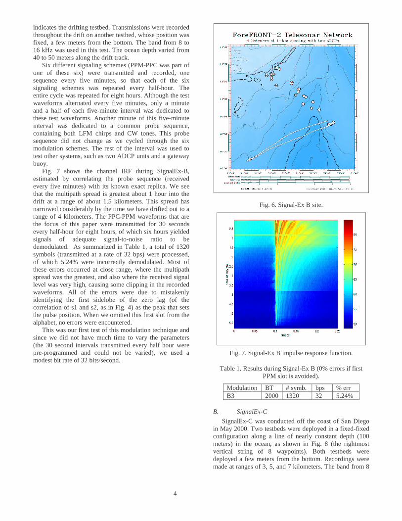
SignalEx-B was conducted in April 2000, on the New England Shelf. During the experiment one of the testbeds was allowed to drift (at a depth of 25-30 meters) from a range of less than 1 km to a range of more than 10 km. Fig. 6 shows a map of the SignalEx-B site. The white line
4
indicates the drifting testbed. Transmissions were recorded throughout the drift on another testbed, whose position was fixed, a few meters from the bottom. The band from 8 to 16 kHz was used in this test. The ocean depth varied from 40 to 50 meters along the drift track.
Six different signaling schemes (PPM-PPC was part of one of these six) were transmitted and recorded, one sequence every five minutes, so that each of the six signaling schemes was repeated every half-hour. The entire cycle was repeated for eight hours. Although the test waveforms alternated every five minutes, only a minute and a half of each five-minute interval was dedicated to these test waveforms. Another minute of this five-minute interval was dedicated to a common probe sequence, containing both LFM chirps and CW tones. This probe sequence did not change as we cycled through the six modulation schemes. The rest of the interval was used to test other systems, such as two ADCP units and a gateway buoy.
Fig. 7 shows the channel IRF during SignalEx-B, estimated by correlating the probe sequence (received every five minutes) with its known exact replica. We see that the multipath spread is greatest about 1 hour into the drift at a range of about 1.5 kilometers. This spread has narrowed considerably by the time we have drifted out to a range of 4 kilometers. The PPC-PPM waveforms that are the focus of this paper were transmitted for 30 seconds every half-hour for eight hours, of which six hours yielded signals of adequate signal-to-noise ratio to be demodulated. As summarized in Table 1, a total of 1320 symbols (transmitted at a rate of 32 bps) were processed, of which 5.24% were incorrectly demodulated. Most of these errors occurred at close range, where the multipath spread was the greatest, and also where the received signal level was very high, causing some clipping in the recorded waveforms. All of the errors were due to mistakenly identifying the first sidelobe of the zero lag (of the correlation of s1 and s2, as in Fig. 4) as the peak that sets the pulse position. When we omitted this first slot from the alphabet, no errors were encountered.
This was our first test of this modulation technique and since we did not have much time to vary the parameters (the 30 second intervals transmitted every half hour were pre-programmed and could not be varied), we used a modest bit rate of 32 bits/second.
Fig. 6. Signal-Ex B site.
Fig. 7. Signal-Ex B impulse response function.
Table 1. Results during Signal-Ex B (0% errors if first PPM slot is avoided).
Modulation BT # symb. bps % err B3 2000 1320 32 5.24%
B. SignalEx-C
SignalEx-C was conducted off the coast of San Diego in May 2000. Two testbeds were deployed in a fixed-fixed configuration along a line of nearly constant depth (100 meters) in the ocean, as shown in Fig. 8 (the rightmost vertical string of 8 waypoints). Both testbeds were deployed a few meters from the bottom. Recordings were made at ranges of 3, 5, and 7 kilometers. The band from 8

5
to 11 kHz was used in this test. Fig. 9 shows the channel IRF at these three ranges (as a function of time) measured by correlating the received probe sequences with their exact replicas. Table 2 shows the results obtained during SignalEx-C. A total of 1854 symbols (at a rate of 25 bits/second) were transmitted. Again, all of our errors (0.14% error at the 5-kilometer range) were due to mistaking the first sidelobe of the zero lag (of our correlation of s1 and s2) for the peak whose location determines the PPM symbol. Once we omitted this PPM slot, we were able to perfectly demodulate all the transmitted symbols.
Fig. 8. Signal-Ex C site.
Fig. 9. Signal-Ex C impulse response function.
Table 2. Results during Signal-Ex C (0% errors if first PPM slot is avoided).
Modulation BT # symb. bps % err C2, 3km 600 700 25 0% C2, 5km 600 700 25 .14% C2, 7km 600 454 25 0%
C. Discussion
The drift of one of the testbeds (0.2 to 0.3 meters/sec) during SignalEx-B produced a slight Doppler shift that had to be corrected. The Doppler was estimated from the probe sequence CW tones, whose duration was long enough that precise synchronization was not needed to achieve adequate Doppler estimates.
We synchronized on the probe LFM sequences. We were able to predict the relative positions of the subsequent individual symbols, as long as we adjusted the nominal symbol interval for the time dilation caused by Doppler.
Note that this demodulation scheme does not require us to resample any waveforms to correct for Doppler. All we require is a waveform with a wide enough band to resolve the separation of peak positions that define our PPM alphabet. We really do not care what that waveform is. We can correct for Doppler by simply changing the length of the correlation interval and modifying our PPM slots accordingly.
Although a LFM chirp is known to be Doppler-tolerant in a matched filter context, it is surprisingly sensitive to Doppler in this PPC-PPM context. If we use the wrong interval length for our correlation of s1 and s2 (see Fig. 4), the two waveforms may destructively interfere at the lags where we are looking for a peak (whose location indicates which PPM symbol we have). This becomes more pronounced as the separation from the zero lag increases.
V. CONCLUSIONS
Passive phase conjugation (PPC) implicitly equalizes the channel by refocusing channel spread using time reversal. We have shown how PPC pulse compression can be used to realize a pulse position modulation (PPM) communication system. This PPC-PPM concept was demonstrated in several shallow water ocean environments during the SignalEx B and C tests in 2000. Bit rates of 32 bps (at 8-16 kHz) and 25 bps (at 8-11 kHz) using single element sources and receivers were reliably demodulated in environments and at ranges being considered for underwater wireless networks. Targeted applications are low power, reliable, always-on communications (e.g. wakeup calls)
Acknowledgments
This work was sponsored by ONR 321SS (Don Davison) and was performed as part of the 6.2 Telesonar Technology project. SignalEx testing was sponsored by ONR 322OM (Tom Curtin and Al Benson). Additional support was provided by ONR 321OA.

6
REFERENCES
[1] M. Stojanovic, J. A. Catipovic, and J. G. Proakis, “Adaptive multi-channel combining and equalization for underwater acoustic communications,” J. Acoust. Soc. Amer., vol. 94, pp. 1621–1631, 1993.
[2] M. Stojanovic, J. A. Catipovic, and J. G. Proakis, “Phase-coherent digital communications for underwater acoustic channels,” IEEE J. Oceanic Eng., vol. 19, pp. 100–111, 1994.
[3] D. R. Jackson and D. R. Dowling, “Phase conjugation in underwater acoustics,” J. Acoust. Soc. Amer., vol. 89, pp. 171–189, 1991.
[4] D. R. Dowling, “Acoustic pulse compression using passive phase-conjugate processing” , J. Acoust. Soc. Am., vol. 95, no. 3, pp. 1450-1458, 1994.
[5] W. A. Kuperman, William S. Hodgkiss, Hee Chun Song, T. Akal, C. Ferla, and Darrell R. Jackson, “Phase conjugation in the ocean: Experimental demonstration of an acoustic time-reversal mirror,” J. Acoust. Soc. Amer., vol. 103, pp. 25–40, 1998.
[6] M. B. Porter, V. K. McDonald, P. A. Baxley, and J. A. Rice, “SignalEx: linking environmental acoustics with the signaling schemes,” OCEANS 2000 MTS/IEEE Conference, vol. 1, pp. 595-600, 2000.