past and present - fanton.com · 84034 Ø 100 55 a b n dimensions (mm) code a b c 84027 Ø 70 45 58...
TRANSCRIPT
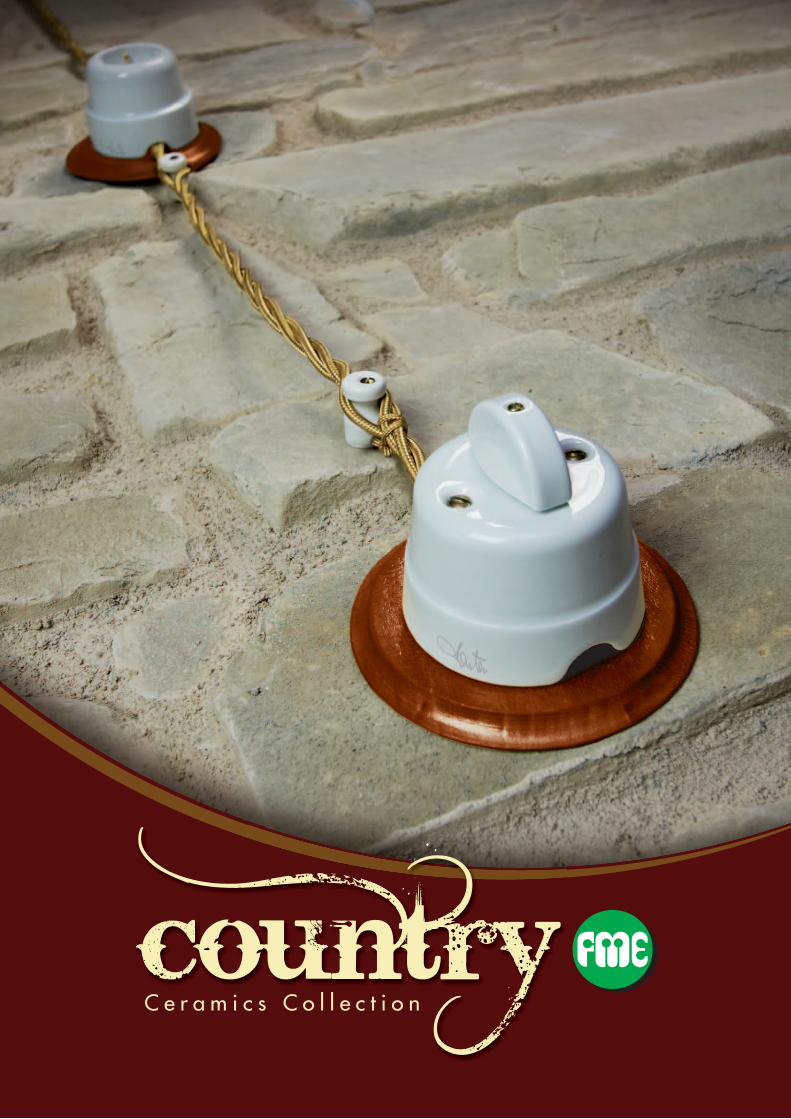
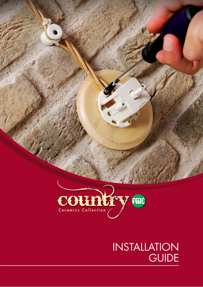
C e r a m i c s C o l l e c t i o n

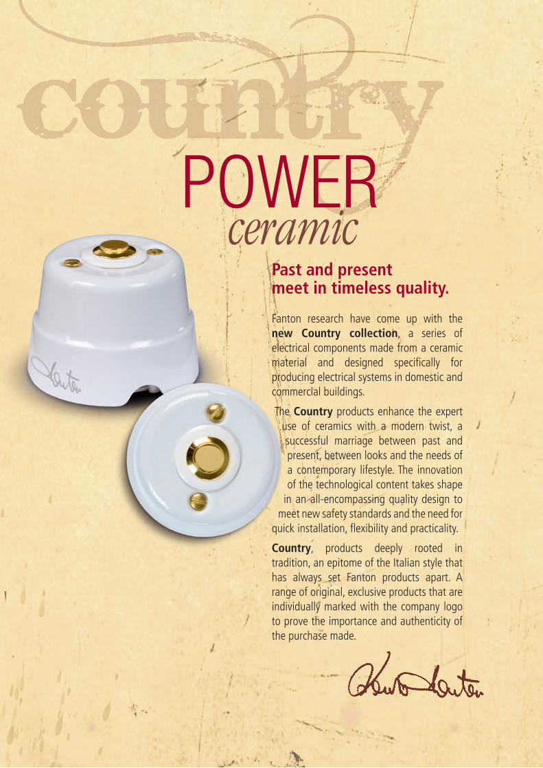
Past and present meet in timeless quality.
Fanton research have come up with the new Country collection, a series of electrical components made from a ceramic material and designed specifi cally for producing electrical systems in domestic and commercial buildings.
The Country products enhance the expert use of ceramics with a modern twist, a successful marriage between past and present, between looks and the needs of a contemporary lifestyle. The innovation of the technological content takes shape
in an all-encompassing quality design to meet new safety standards and the need for
quick installation, fl exibility and practicality.
Country, products deeply rooted in tradition, an epitome of the Italian style that has always set Fanton products apart. A range of original, exclusive products that are individually marked with the company logo to prove the importance and authenticity of the purchase made.
POWERceramic

The exclusive soul of the Country products guarantees quick and easy installation, a great deal of fl exibility and absolute safety, thanks to the innovative assembly system with internal socket module.
Country SystemInnovation comesfrom within!
installation, a great deal of fl exibility
System
Ceramic cover
Socket module
Wooden base
n QuiCker iNstallatioN thanks to the easy assembly and simple wiring.
1 2 3
advantages of the Country system
n less risk of accidental breakage of
ceramics during installation since they can be fi tted once
installation of the system has been completed.
n greater proteCtioN should the ceramics break
accidentally since the socket module allows you to keep using the component in
complete safety.
n greater FlexiBilitY in changing the socket module,
as the ceramic cover can be kept due to the Keystone standard.
n greater saFetY thanks to the cable clamp.
1
2
3
4
6
7
8
5
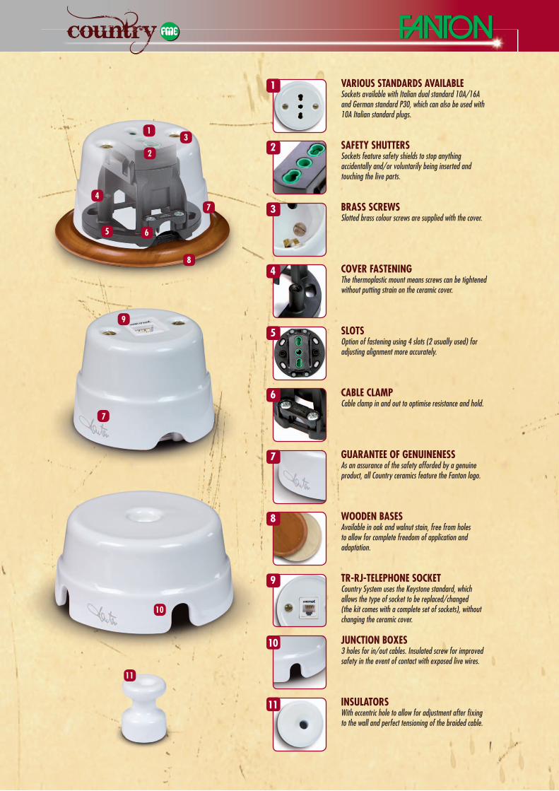
various staNdards availaBleSockets available with Italian dual standard 10A/16A and German standard P30, which can also be used with 10A Italian standard plugs.
1
tr-rJ-telepHoNe soCketCountry System uses the Keystone standard, which allows the type of socket to be replaced/changed (the kit comes with a complete set of sockets), without changing the ceramic cover.
9
JuNCtioN Boxes3 holes for in/out cables. Insulated screw for improved safety in the event of contact with exposed live wires.
10
iNsulatorsWith eccentric hole to allow for adjustment after fi xing to the wall and perfect tensioning of the braided cable.
11
saFetY sHuttersSockets feature safety shields to stop anything accidentally and/or voluntarily being inserted and touching the live parts.
2
Brass sCreWsSlotted brass colour screws are supplied with the cover.
3
Cover FasteNiNgThe thermoplastic mount means screws can be tightened without putting strain on the ceramic cover.
4
slotsOption of fastening using 4 slots (2 usually used) for adjusting alignment more accurately.
5
CaBle ClaMpCable clamp in and out to optimise resistance and hold.
6
guaraNtee oF geNuiNeNessAs an assurance of the safety afforded by a genuine product, all Country ceramics feature the Fanton logo.
7
WoodeN BasesAvailable in oak and walnut stain, free from holes to allow for complete freedom of application and adaptation.
8
9
10
11
7
Technical ceramicsNot all ceramics are the same. There are various types of components available on the market and they are classifi ed as follows:
Country products are made from a ceramic material that is termed “technical” due to the high percentage of alumina contained in the mixture.
The Country products’ hidden qualitiesNot all the qualities of Country products are immediately visible, such as the type of ceramic used. All our products are created using a particular type of ceramic that, thanks to the alumina content, makes it signifi cantly superior to other ceramics and porcelain. This is why it is defi ned as ‘technical ceramic’. The Alumina offers the ceramic material a combination of unique mechanical and electrical properties:
• Good thermal stability;• Not subject to oxidation;• Excellent hardness - material akin to diamonds;• High wear resistance - a ceramic component in applications
where it is subject to wear offers 10-14 times the service life of the same component made of steel;
• Resistance to corrosion in acidic or alkaline environments;• Good heat insulator - excellent dielectric properties when used
with direct current;• Good heat insulator.
The differences that matter• Many ceramic products on the market are actually made from
Porcelain, which is inferior to the Technical Ceramic material in one peculiar respect: impact strength.
• The specifi c weight of a porcelain product (comparable to the Country series) is approximately 2.33, as compared with alumina-based technical ceramics, which is 3.55 kg/dm³.
• The tolerances shown on the images (+/-1%) are ample and therefore shared.
• The hardness is evident when products made from Technical Ceramics and Porcelain are tested. An attempt to break them with a normal pair of pliers reveals how the Alumina-based
Technical Ceramic material breaks like glass and requires a lot of force, while Porcelain products break easily, causing the product to crumble. Where the Alumina-based Technical Ceramic material is broken, the visible texture is fi ne, more compact and hence stronger, as opposed to the porous appearance of Porcelain.
• Another factor that sets the two materials apart is the purity of Technical Ceramics, which are whitish and smooth in appearance due to the Alumina content, unlike Porcelain, which is greyish in colour.
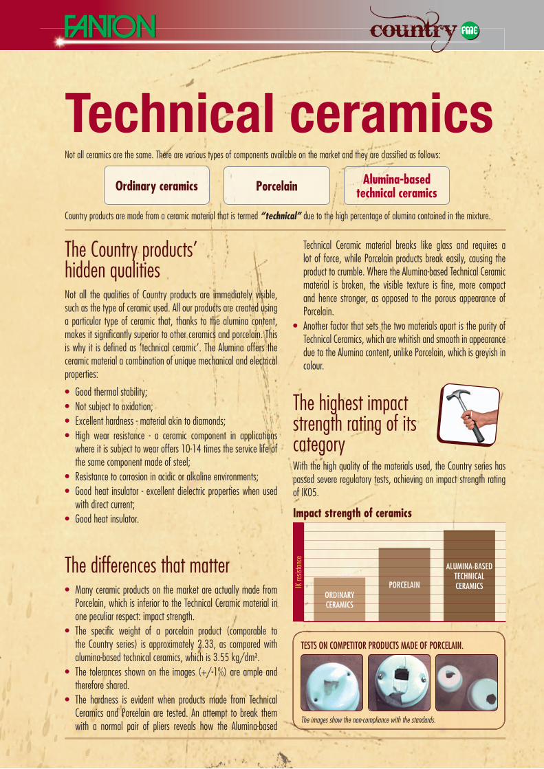
The highest impact strength rating of its categoryWith the high quality of the materials used, the Country series has passed severe regulatory tests, achieving an impact strength rating of IK05.
impact strength of ceramics
IK res
istan
ce
ORDINARY CERAMICS
PORCELAIN
ALUMINA-BASED TECHNICAL CERAMICS
ordinary ceramics porcelain alumina-based technical ceramics
The images show the non-compliance with the standards.
TESTS ON COMPETITOR PRODUCTS MADE OF PORCELAIN.
PERCHÈ QUESTE FIGURE HANNO SPAZIATURE DIVERSE?
C e r a m i c s C o l l e c t i o nC e r a m i c s C o l l e c t i o n
SwiTcheSANd SOckeTS
SwiTcheSANd SOckeTS
...many items in our collection
are IMQ certifi ed.
The only
ones with
the mark

84001
84003
SWITCHES AND SOCKETS
n 10AX - 250V~ switch/2-way switchCode Colour single package packing unit
84001 nnnn Box 12
n Rotating button 10A - 250V~Code Colour single package packing unit
84002 nnnn Box 12
n 2A - 48V ceramic brass buttonCode Colour single package packing unit
84003 nnnn Box 12
A
n diMeNsioNs (mm)Code a B C d
84001 Ø 70 45 65 37
84002 Ø 70 45 65 37
B
C
D
n diMeNsioNs (mm)Code a B C
84003 Ø 70 56 37A C
B
cEI EN 6 06 6 9-1
coN
FoRmS To THE STA
ND
ARD
cEI EN60669-1
cEI EN 6 06 6 9-1
coN
FoRmS To THE STA
ND
ARD
cEI EN60669-1
84010
84011
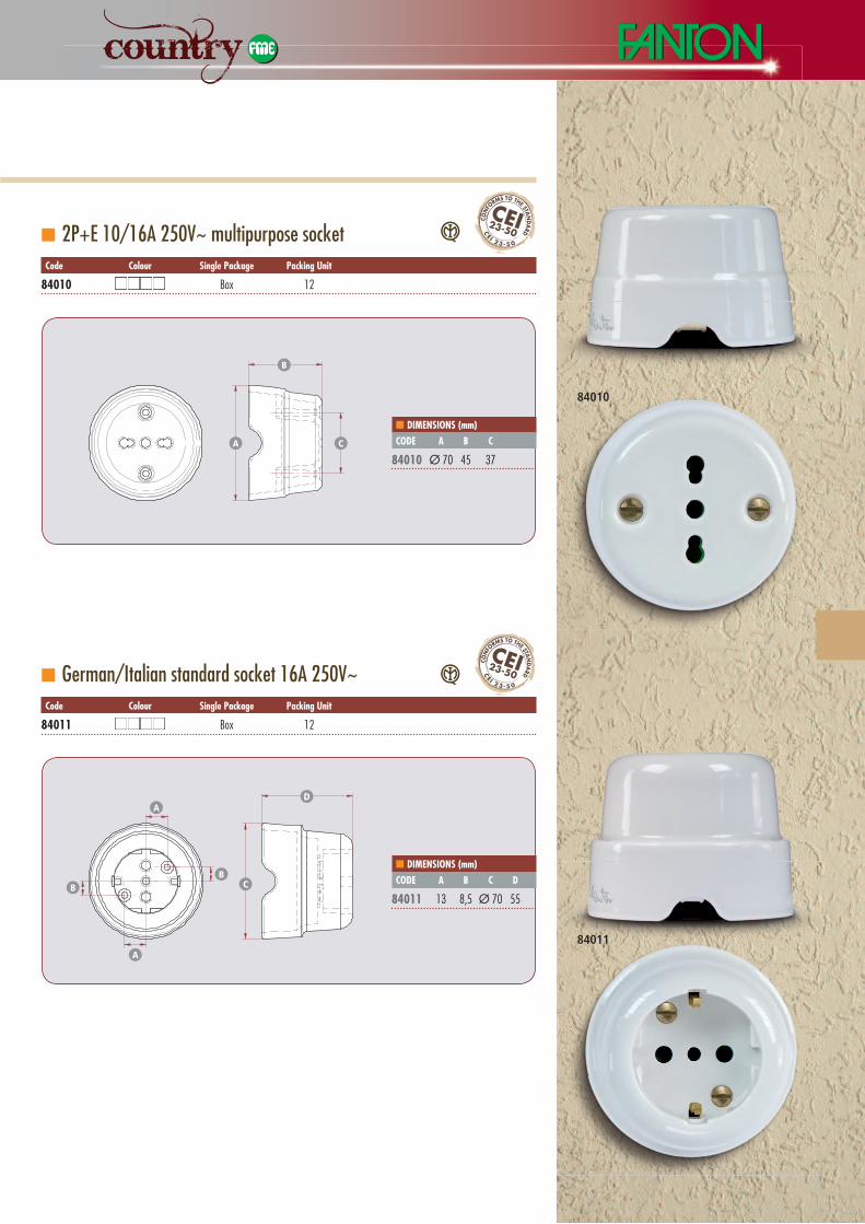
n 2P+E 10/16A 250V~ multipurpose socketCode Colour single package packing unit
84010 nnnn Box 12
n German/Italian standard socket 16A 250V~Code Colour single package packing unit
84011 nnnn Box 12
SWITCHES AND SOCKETS
n diMeNsioNs (mm)Code a B C
84010 Ø 70 45 37
n diMeNsioNs (mm)Code a B C d
84011 13 8,5 Ø 70 55
A C
B
A
BB
A
D
C
cE I 23-5 0
cEI23-50
coN
FoRmS To THE STA
ND
ARD
cE I 23-5 0
cEI23-50
coN
FoRmS To THE STA
ND
ARD
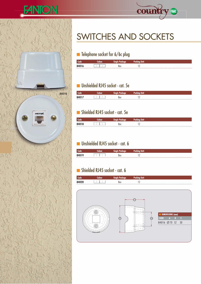
n Telephone socket for 6/6c plugCode Colour single package packing unit
84016 nnnn Box 12
n Unshielded RJ45 socket - cat. 5eCode Colour single package packing unit
84017 nnnn Box 12
n Shielded RJ45 socket - cat. 5eCode Colour single package packing unit
84018 nnnn Box 12
n Unshielded RJ45 socket - cat. 6Code Colour single package packing unit
84019 nnnn Box 12
n Shielded RJ45 socket - cat. 6Code Colour single package packing unit
84020 nnnn Box 12
n diMeNsioNs (mm)Code a B C
84016 Ø 70 52 30A C
B
84016
SWITCHES AND SOCKETS
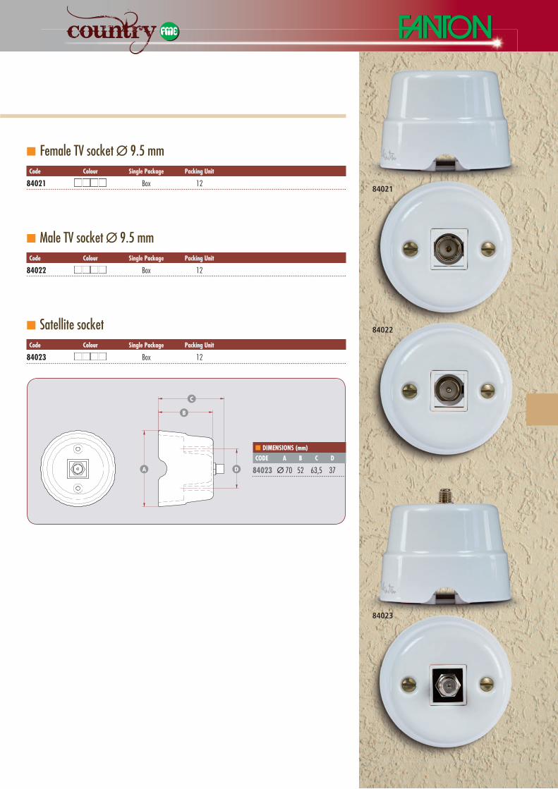
n Female TV socket Ø 9.5 mmCode Colour single package packing unit
84021 nnnn Box 12
n Male TV socket Ø 9.5 mmCode Colour single package packing unit
84022 nnnn Box 12
n Satellite socketCode Colour single package packing unit
84023 nnnn Box 12
n diMeNsioNs (mm)Code a B C d
84023 Ø 70 52 63,5 37A D
B
C
84021
84022
84023
SWITCHES AND SOCKETS


C e r a m i c s C o l l e c t i o nC e r a m i c s C o l l e c t i o n
AcceSSOrieSAcceSSOrieS...many items in our collection
are IMQ certifi ed.
The only
ones with
the mark
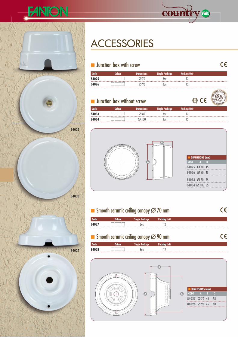
n Junction box with screw Code Colour dimensions single package packing unit
84025 nnnn Ø 70 Box 12
84026 nnnn Ø 90 Box 12
n Junction box without screw Code Colour dimensions single package packing unit
84033 nnnn Ø 80 Box 12
84034 nnnn Ø 100 Box 12
n Smooth ceramic ceiling canopy Ø 70 mm Code Colour single package packing unit
84027 nnnn Box 12
n Smooth ceramic ceiling canopy Ø 90 mm Code Colour single package packing unit
84028 nnnn Box 12
ACCESSORIES
n diMeNsioNs (mm)Code a B
84025 Ø 70 45
84026 Ø 90 45
84033 Ø 80 55
84034 Ø 100 55
A
B
n diMeNsioNs (mm)Code a B C
84027 Ø 70 45 58
84028 Ø 90 45 80
A C
B
84025
84027
84033
coN
FoRmS To THE STAN
DA
RD
cEI EN60670-22
cEI EN
6 06 7 0-22
ACCESSORIES
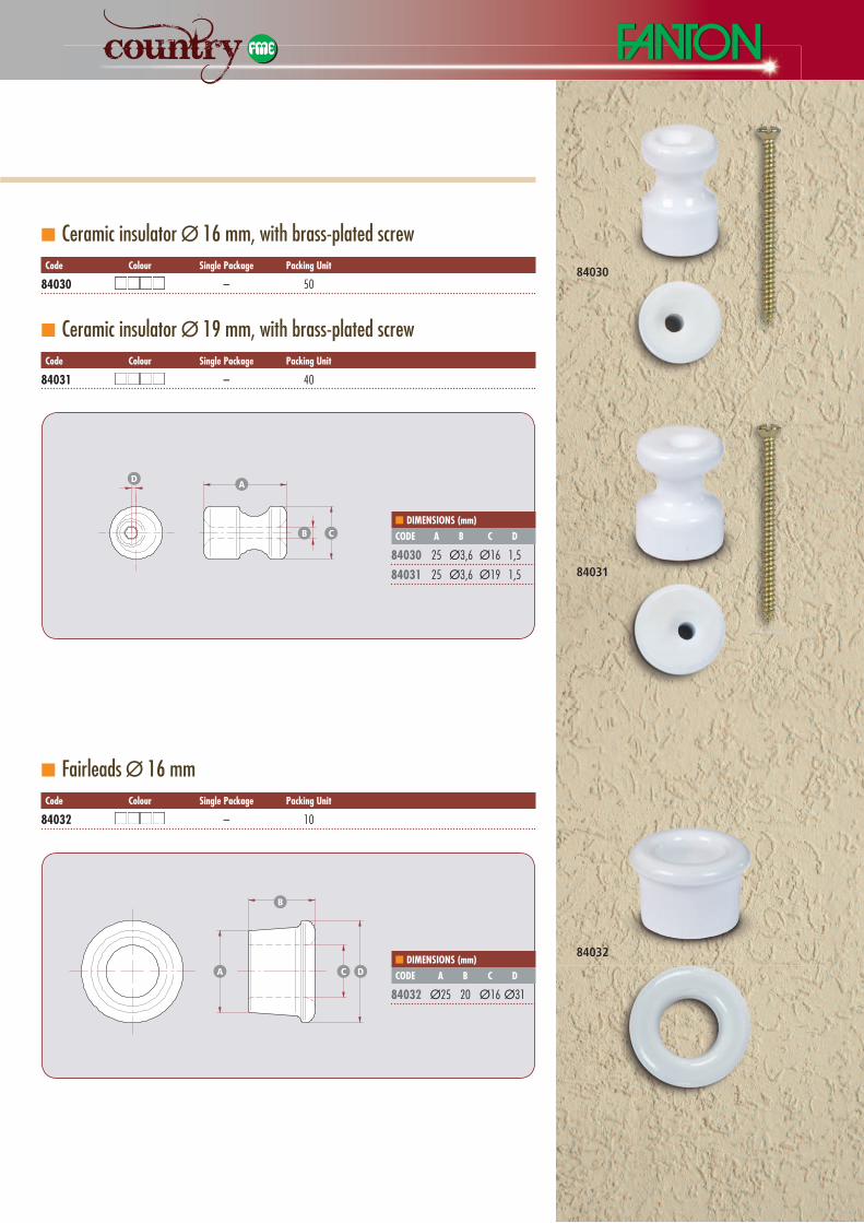
n Ceramic insulator Ø 16 mm, with brass-plated screwCode Colour single package packing unit
84030 nnnn – 50
n Ceramic insulator Ø 19 mm, with brass-plated screwCode Colour single package packing unit
84031 nnnn – 40
n Fairleads Ø 16 mmCode Colour single package packing unit
84032 nnnn – 10
n diMeNsioNs (mm)Code a B C d
84030 25 Ø3,6 Ø16 1,5
84031 25 Ø3,6 Ø19 1,5
A
B C
D
n diMeNsioNs (mm)Code a B C d
84032 Ø25 20 Ø16 Ø31
A DC
B
84030
84032
84031
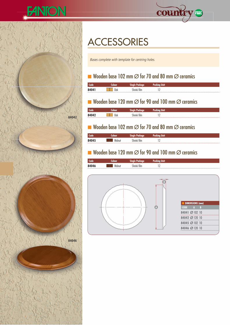
n Wooden base 102 mm Ø for 70 and 80 mm Ø ceramicsCode Colour single package packing unit
84041 nn Oak Shrink fi lm 12
n Wooden base 120 mm Ø for 90 and 100 mm Ø ceramicsCode Colour single package packing unit
84042 nn Oak Shrink fi lm 12
n Wooden base 102 mm Ø for 70 and 80 mm Ø ceramicsCode Colour single package packing unit
84045 nn Walnut Shrink fi lm 12
n Wooden base 120 mm Ø for 90 and 100 mm Ø ceramicsCode Colour single package packing unit
84046 nn Walnut Shrink fi lm 12
n diMeNsioNs (mm)Code a B
84041 Ø 102 10
84042 Ø 120 10
84045 Ø 102 10
84046 Ø 120 10
A
B
84042
84046
ACCESSORIES
Bases complete with template for centring holes.

C e r a m i c s C o l l e c t i o nC e r a m i c s C o l l e c t i o n
LIGHTING RANGE
SiLk BrAidedcABLeS
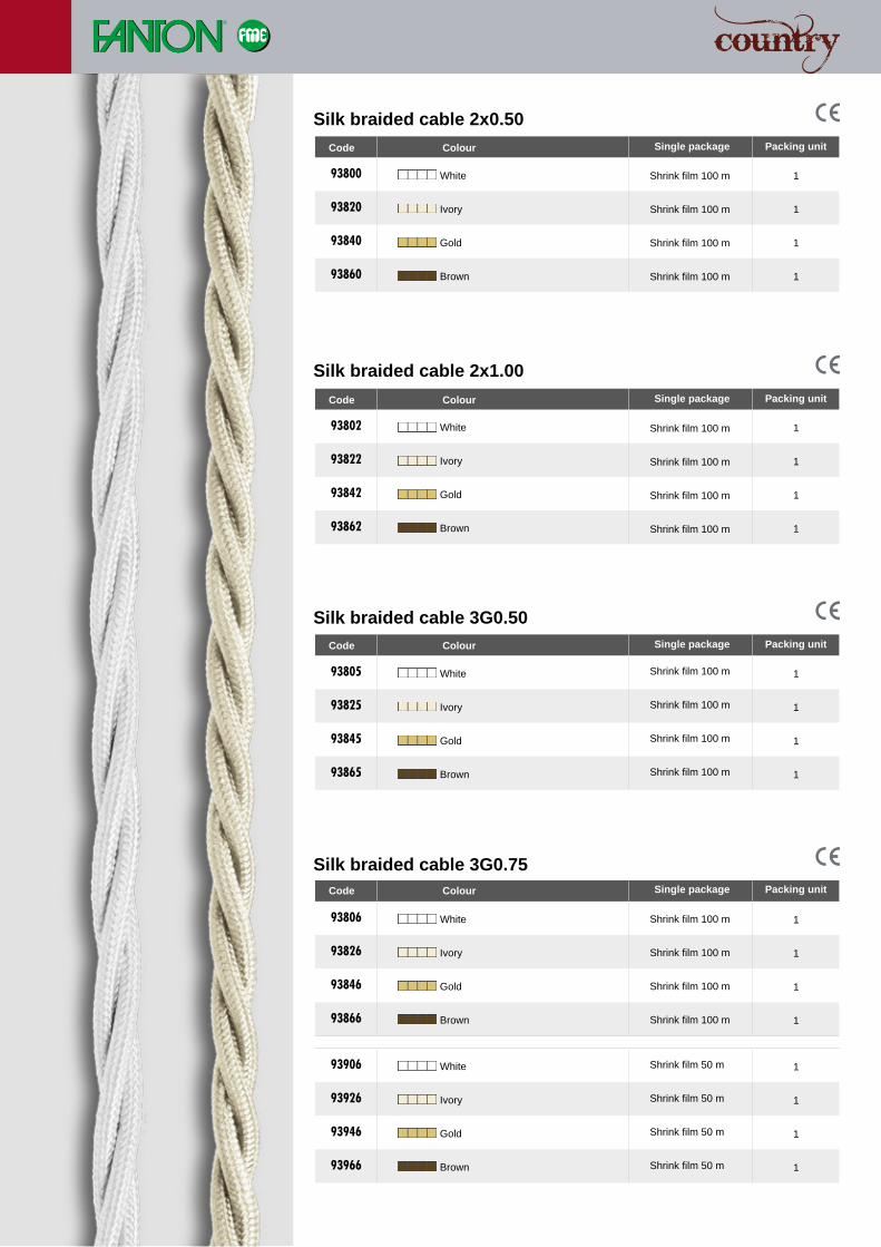
Code Colour Single package Packing unit
93800 nnnn White Shrink film 100 m 1
93820 nnnn Ivory Shrink film 100 m 1
93840 nnnn Gold Shrink film 100 m 1
93860 nnnn Brown Shrink film 100 m 1
93805 nnnn 1
93825 nnnn 1
93845 nnnn 1
93865 nnnn 1
93802 nnnn 1
93822 nnnn 1
93842 nnnn 1
93862 nnnn 1
93806 nnnn 1
93826 nnnn 1
93846 nnnn 1
93866 nnnn 1
93906 nnnn 1
93926 nnnn 1
93946 nnnn 1
93966 nnnn 1
Silk braided cable 2x0.50
Silk braided cable 2x1.00
Silk braided cable 3G0.50
Silk braided cable 3G0.75
Code Colour Single package Packing unit
Code Colour Single package Packing unit
Code Colour Single package Packing unit
White
Ivory
Gold
Brown
White
Ivory
Gold
Brown
White
Ivory
Gold
Brown
White
Ivory
Gold
Brown
Shrink film 100 m
Shrink film 100 m
Shrink film 100 m
Shrink film 100 m
Shrink film 100 m
Shrink film 100 m
Shrink film 100 m
Shrink film 100 m
Shrink film 100 m
Shrink film 100 m
Shrink film 100 m
Shrink film 100 m
Shrink film 50 m
Shrink film 50 m
Shrink film 50 m
Shrink film 50 m
Code Colour Single package Packing unit
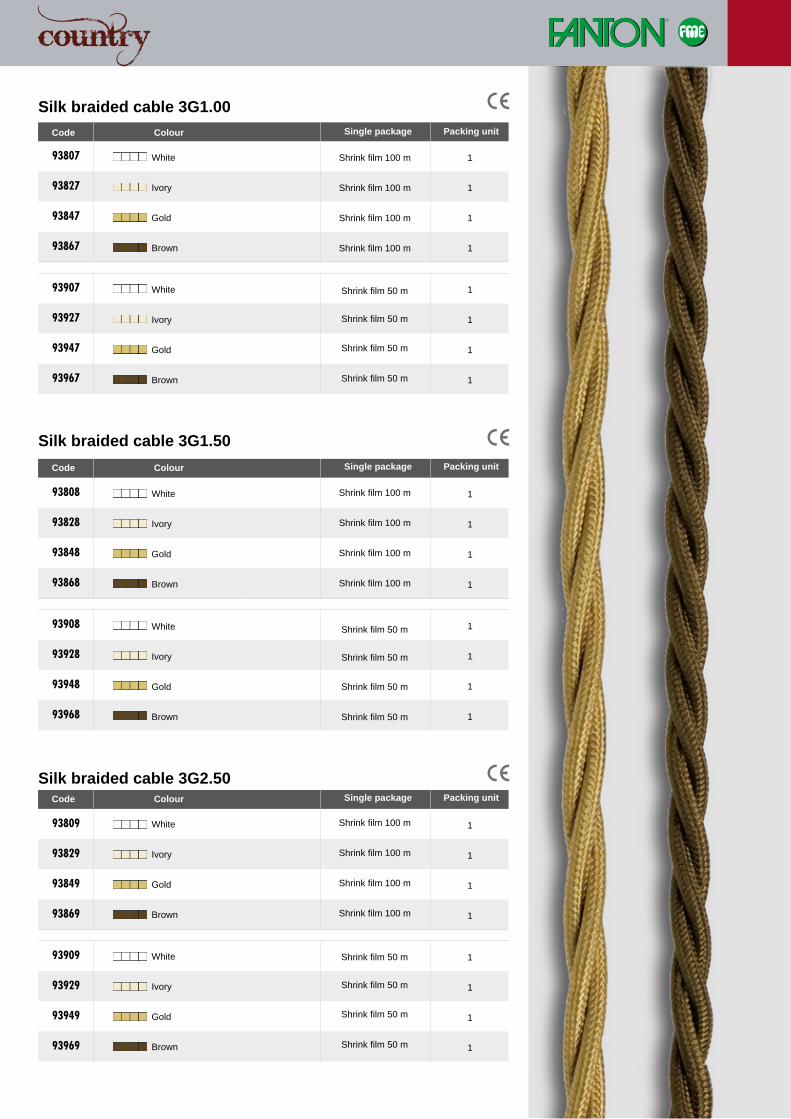
93807 nnnn 1
93827 nnnn 1
93847 nnnn 1
93867 nnnn 1
93907 nnnn 1
93927 nnnn 1
93947 nnnn 1
93967 nnnn 1
93809 nnnn 1
93829 nnnn 1
93849 nnnn 1
93869 nnnn 1
93909 nnnn 1
93929 nnnn 1
93949 nnnn 1
93969 nnnn 1
93808 nnnn 1
93828 nnnn 1
93848 nnnn 1
93868 nnnn 1
93908 nnnn 1
93928 nnnn 1
93948 nnnn 1
93968 nnnn 1
Silk braided cable 3G1.00
Silk braided cable 3G1.50
Silk braided cable 3G2.50
White
Ivory
Gold
Brown
White
Ivory
Gold
Brown
White
Ivory
Gold
Brown
White
Ivory
Gold
Brown
White
Ivory
Gold
Brown
White
Ivory
Gold
Brown
Shrink film 100 m
Shrink film 100 m
Shrink film 100 m
Shrink film 100 m
Shrink film 100 m
Shrink film 100 m
Shrink film 100 m
Shrink film 100 m
Shrink film 100 m
Shrink film 100 m
Shrink film 100 m
Shrink film 100 m
Shrink film 50 m
Shrink film 50 m
Shrink film 50 m
Shrink film 50 m
Shrink film 50 m
Shrink film 50 m
Shrink film 50 m
Shrink film 50 m
Shrink film 50 m
Shrink film 50 m
Shrink film 50 m
Shrink film 50 m
Code Colour Single package Packing unit
Code Colour Single package Packing unit
Code Colour Single package Packing unit
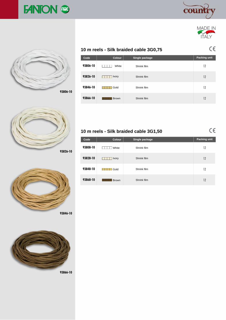
10 m reels - Silk braided cable 3G0,75
10 m reels - Silk braided cable 3G1,50
93806-10 nnnn 12
93826-10 nnnn 12
93846-10 nnnn 12
93866-10 nnnn 12
93808-10 nnnn 12
93828-10 nnnn 12
93848-10 nnnn 12
93868-10 nnnn 12
93866-10
93806-10
93826-10
93846-10
White
Ivory
Gold
Brown
White
Ivory
Gold
Brown
Shrink film
Shrink film
Shrink film
Shrink film
Shrink film
Shrink film
Shrink film
Shrink film
Code
Colour
Single package Packing unit
Code Single package Packing unit
Colour
C e r a m i c s C o l l e c t i o nC e r a m i c s C o l l e c t i o n
iNSTALLATiONguide
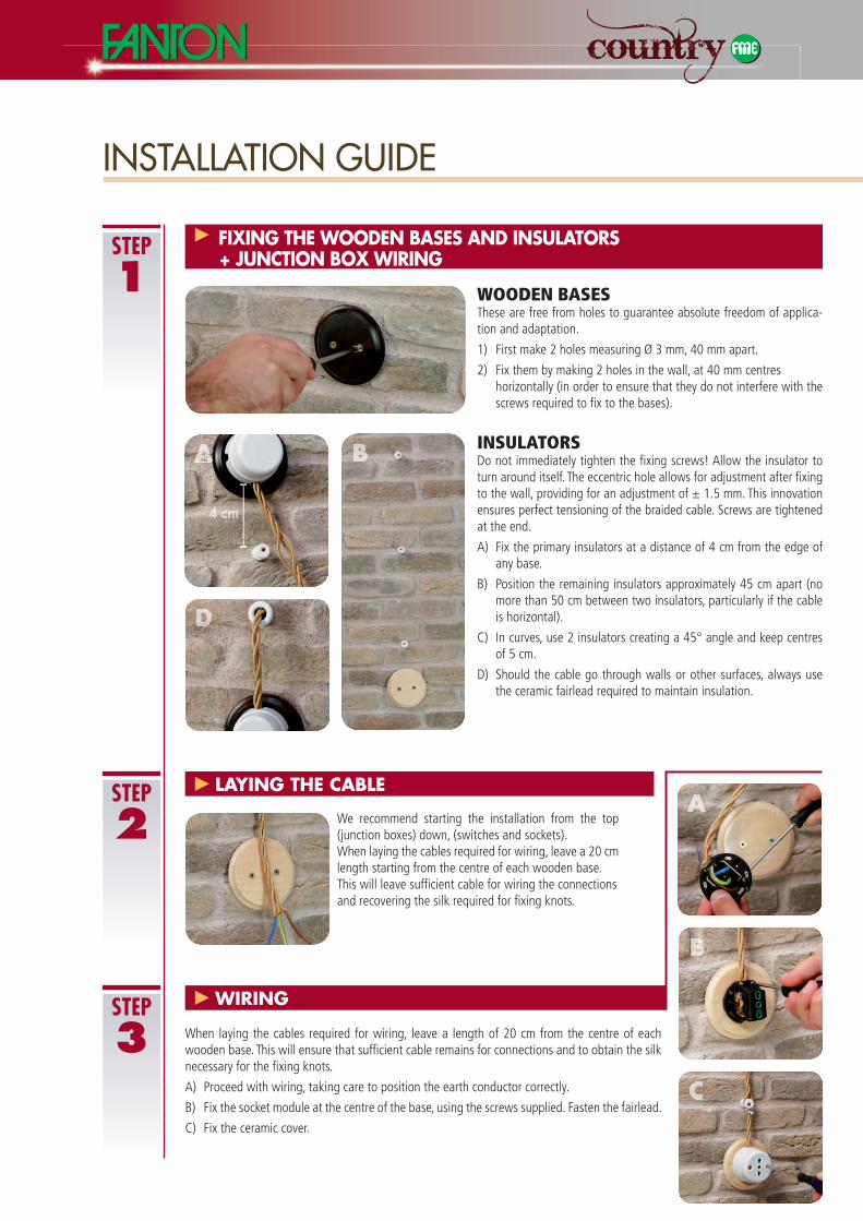
INSULATORSDo not immediately tighten the fi xing screws! Allow the insulator to turn around itself. The eccentric hole allows for adjustment after fi xing to the wall, providing for an adjustment of ± 1.5 mm. This innovation ensures perfect tensioning of the braided cable. Screws are tightened at the end.
A) Fix the primary insulators at a distance of 4 cm from the edge of any base.
B) Position the remaining insulators approximately 45 cm apart (no more than 50 cm between two insulators, particularly if the cable is horizontal).
C) In curves, use 2 insulators creating a 45° angle and keep centres of 5 cm.
D) Should the cable go through walls or other surfaces, always use the ceramic fairlead required to maintain insulation.
step
1
INSTALLATION GUIDE
WOODEN BASESThese are free from holes to guarantee absolute freedom of applica-tion and adaptation.
1) First make 2 holes measuring Ø 3 mm, 40 mm apart.
2) Fix them by making 2 holes in the wall, at 40 mm centres horizontally (in order to ensure that they do not interfere with the
screws required to fi x to the bases).
FIXING THE WooDEN BASES AND INSULAToRS + JUNcTIoN BoX WIRING
We recommend starting the installation from the top (junction boxes) down, (switches and sockets). When laying the cables required for wiring, leave a 20 cmlength starting from the centre of each wooden base. This will leave suffi cient cable for wiring the connectionsand recovering the silk required for fi xing knots.
LAYING THE cABLE
When laying the cables required for wiring, leave a length of 20 cm from the centre of each wooden base. This will ensure that suffi cient cable remains for connections and to obtain the silk necessary for the fi xing knots.
A) Proceed with wiring, taking care to position the earth conductor correctly.
B) Fix the socket module at the centre of the base, using the screws supplied. Fasten the fairlead.
C) Fix the ceramic cover.
WIRING
A
D
A
B
c
4 cm
step
2
step
3
B
step
4
step
5
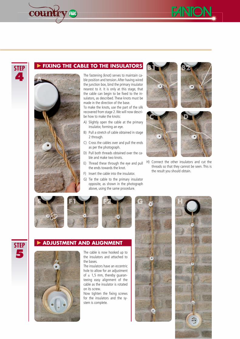
The fastening (knot) serves to maintain ca-ble position and tension. After having wired the junction box, bind the primary insulator nearest to it. It is only at this stage, that the cable can begin to be fi xed to the in-sulators, as described. These knots must be made in the direction of the base. To make the knots, use the part of the silk recovered from stage 2. We will now descri-be how to make the knots:
A) Slightly open the cable at the primary insulator, forming an eye.
B) Pull a stretch of cable obtained in stage 2 through.
C) Cross the cables over and pull the ends as per the photograph.
D) Pull both threads obtained over the ca-ble and make two knots.
E) Thread these through the eye and pull the ends towards the knot.
F) Insert the cable into the insulator.
G) Tie the cable to the primary insulator opposite, as shown in the photograph above, using the same procedure.
H) Connect the other insulators and cut the threads so that they cannot be seen. This is the result you should obtain.
A
E F1 F2 G H
The cable is now hooked up to the insulators and attached to the bases. The insulators have an eccentrichole to allow for an adjustment of ± 1,5 mm, thereby guaran-teeing easy alignment of the cable as the insulator is rotated on its screw. Now tighten the fi xing screws for the insulators and the sy-stem is complete.
ADJUSTmENT AND ALIGNmENT
FIXING THE cABLE To THE INSULAToRS B1 B2
c D