pattern-based analysis of uml activity diagrams b… · pattern-based analysis of uml activity...
TRANSCRIPT

Pattern-based Analysis of UML Activity Diagrams
Petia Wohed1, Wil M.P. van der Aalst2,3, Marlon Dumas3, Arthur H.M. ter Hofstede3
and Nick Russell3
1 Centre de Recherche en Automatique de Nancy, Universite Henri Poincare, Nancy 1BP239, 54506 Vandoeuvre les Nancy, France
[email protected] Department of Technology Management, Eindhoven University of Technology
GPO Box 513, NL5600 MB Eindhoven, The [email protected]
3 Centre for Information Technology Innovation, Queensland University of TechnologyGPO Box 2434, Brisbane QLD 4001, Australia{m.dumas, a.terhofstede, n.russell}@qut.edu.au
Abstract. The Unified Modelling Language (UML) is a well-known family ofnotations for software modelling. Recently, a new version of UML has been re-leased. In this paper we examine the Activity Diagrams notation of this latestversion of UML in terms of a collection of patterns developed for assessing con-trol flow and data flow capabilities of languages used in the area of process-awareinformation systems. The purpose of this analysis is to assess relative strengthsand weaknesses of control and data flow specification in Activity Diagrams and toidentify ways of addressing potential deficiencies. In addition, the pattern-basedanalysis will yield typical solutions to practical process modelling problems andexpose some of the ambiguities in the current UML 2.0 draft specification [9].Keywords: UML, Activity Diagrams, Workflow Patterns, YAWL
1 Introduction
The Unified Modelling Language (UML), not seldom referred to as a de facto standardfor software modelling, has recently undergone a significant upgrade to a new majorversion, namely UML 2.01. Being a multi-purpose language, UML offers a variety ofnotations for capturing different aspects of software structure and behaviour. One ofthese notations, namely Activity Diagrams (AD), is intended for modelling computa-tional and business/organisational processes.
If the UML AD notation is to be adopted as a standard for business process mod-elling, it should compare favourably with other notations in this space. Evaluating andcomparing modelling notations, particularly in the area of business processes, is a del-icate endeavour. Evaluations in terms of case studies may lead to valuable insights, butthe conclusions are difficult to generalise due to their restricted scope. On the otherhand, evaluations in terms of ontologies, such as the BWW ontology [6, 10], lead tocoarse-grained results since these ontologies are composed of highly general concepts
1 http://www.uml.org

whose pertinence and manifestation in the context of business processes have not yetbeen studied.
The workflow patterns [3, 11] constitute a more specialised evaluation framework.Originally developed as an instrument to evaluate languages supported by workflowsystems, these patterns have been used by several authors to evaluate languages forprocess-aware information systems development [5, 14, 13, 8]. Also, while originallyrestricted to the control flow perspective (i.e. the ordering of activities) these patternshave been extended to the data perspective2. In addition, a workflow definition language(namely YAWL [1]) capturing most of the patterns has been designed and implemented.
This paper provides an evaluation of UML AD (version 2.0) in terms of the work-flow patterns. The contributions of this evaluation are:
– The identification of some limitations in UML AD and recommendations for ad-dressing these with minimal disruption to the current design of the language.
– Discussions on how to capture the patterns in UML AD which provide elements ofreusable knowledge for process designers that encounter these patterns.
– A critical analysis of the UML 2.0 AD Draft Specification of the OMG, e.g., point-ing out many ambiguities in the current specification [9].
Note that an evaluation of UML AD version 1.4 in terms of these patterns has beenpreviously reported [5]. This evaluation led to the identification of limitations partlyaddressed by UML 2.0. However, while in UML 1.4 activity diagrams are based onstatecharts, in UML 2.0 they have a semantics defined in terms of token flow inspiredby (though not fully based on) Petri nets. Thus, the evaluation of UML 2.0 leads toquite different results than the one for UML 1.4. Also, it may be noted that a previousattempt at evaluating UML 2.0 AD has been conducted by White [13], who comparesUML AD with the Business Process Modelling Notation (BPMN) designed by himself.However, some of the results reported by White may be questioned as explained in therest of this paper. Furthermore, neither White’s evaluation, nor the previous evaluationof UML 1.4 AD cover the data perspective.
The rest of the paper is organised as follows. Section 2 briefly introduces the UML2.0 AD notation. Sections 3 and 4 report on the evaluation of UML AD in terms ofthe control-flow and the data patterns respectively. Finally, Section 5 summarises theresults and concludes.
2 Overview of UML2.0 AD
In UML 2.0 AD the fundamental unit of behaviour specification is Action. “An actiontakes a set of inputs and converts them to a set of outputs, though either or both setsmay be empty.” [9], p. 2033. Actions may also modify the state of the system. There arethree types of actions, namely: Invocation Actions, used for performing operation calls,signal sending and accept event actions; Read and Write Actions, for accessing andmodifying objects and their values; and Computation Actions, transforming input val-ues into output values. The language provides further a very detailed action taxonomy,
2 Extensions are underway to cover the other perspectives, but these are not discussed here.3 In the remainder of this paper page numbers without reference refer to [9].
2
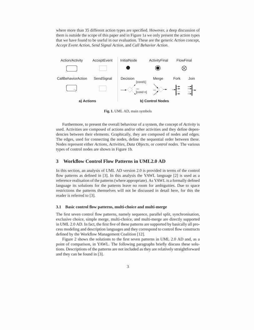
where more than 35 different action types are specified. However, a deep discussion ofthem is outside the scope of this paper and in Figure 1a we only present the action typesthat we have found to be useful in our evaluation. These are the generic Action concept,Accept Event Action, Send Signal Action, and Call Behavior Action.
a) Actions
Action/Activity AcceptEvent
Fork JoinDecision Merge
b) Control Nodes
......
[cond1]
[cond n]... ...
InitialNode ActivityFinal FlowFinal
SendSignalCallBehaviorAction
Fig. 1. UML AD, main symbols
Furthermore, to present the overall behaviour of a system, the concept of Activity isused. Activities are composed of actions and/or other activities and they define depen-dencies between their elements. Graphically, they are composed of nodes and edges.The edges, used for connecting the nodes, define the sequential order between these.Nodes represent either Actions, Activities, Data Objects, or control nodes. The varioustypes of control nodes are shown in Figure 1b.
3 Workflow Control Flow Patterns in UML2.0 AD
In this section, an analysis of UML AD version 2.0 is provided in terms of the controlflow patterns as defined in [3]. In this analysis the YAWL language [2] is used as areference realisation of the patterns (where appropriate). As YAWL is a formally definedlanguage its solutions for the patterns leave no room for ambiguities. Due to spacerestrictions the patterns themselves will not be discussed in detail here, for this thereader is referred to [3].
3.1 Basic control flow patterns, multi-choice and multi-merge
The first seven control flow patterns, namely sequence, parallel split, synchronisation,exclusive choice, simple merge, multi-choice, and multi-merge are directly supportedin UML 2.0 AD. In fact, the first five of these patterns are supported by basically all pro-cess modeling and description languages and they correspond to control flow constructsdefined by the Workflow Management Coalition [12].
Figure 2 shows the solutions to the first seven patterns in UML 2.0 AD and, as apoint of comparison, in YAWL. The following paragraphs briefly discuss these solu-tions. Descriptions of the patterns are not included as they are relatively straightforwardand they can be found in [3].
3

c) YAWL AND-split task
g) YAWL XOR-split task
e) AND-join task
i) YAWL XOR-join task
a) Sequence in YAWL
b) Control flow in UML
B
CA
Parallel Split Synchronisation
Exclusive Choice Simple Merge/Multi-merge
d) UML Explicit AND-split
Sequence
B
CA
B
C
A
B
C
A
f) UML Explicit AND-join
B
C
AB
C
A
B
C
A
j) UML XOR-join
A
B
C
[Guard1]
[Guard2]
h) UML Explicit XOR-split
Multi-Choice
A
[Guard1]
[Guard2]
B
C
k) YAWL OR-split task
B
CA
l) UML OR-split
[Guard1]
[Guard2]
Fig. 2. Elementary Control Flow in UML and in YAWL
There are two ways of representing sequence in YAWL (see Figure 2a). Two taskscan be connected directly, or they can have a condition (which corresponds to the con-cept of “place” in Petri nets) in between. In case two tasks are connected directly thecondition in between exists in a formal sense, it is just not shown graphically. In UML,this basic pattern is solved in a very similar manner (see Figure 2b), i.e. through a con-trol flow arrow (p. 315), though UML does not explicitly support the notion of statehence there is no equivalent concept to the YAWL condition.
The parallel split is captured in YAWL by an AND-split (see Figure 2c). In UMLit is captured by a ForkNode, represented as a bar with one incoming edge and two ormore outgoing edges (p. 334) (see Figure 2d). Furthermore, as “an action may have setsof incoming and outgoing activity edges...” (p. 280) and “when completed, an actionexecution offers [..] control tokens on all its control edges” (p. 281) the parallel splitcan also be modelled implicitly, by drawing the outgoing edges directly from the actionnode and omitting the fork node.
4
Synchronisation in YAWL is captured through the AND-join (see Figure 2e). InUML 2.0 AD, the construct used for synchronisation is the JoinNode, i.e. a controlnode depicted as a bar with multiple incoming edges and one outgoing edge (p. 339).Furthermore, as a JoinNode provides the possibility for the specification of a condition(through a joinSpec expression) the default value “and” has to be used to guaranteesynchronisation of all its incoming edges (Figure 2f). Similarly to the parallel splitsolution, here also an implicit notation, where the JoinNode is omitted, is offered. Thesemantics of this solution is that “an action execution is created when all its [..] controlflows prerequisites are satisfied” (p. 281).
The exclusive choice in YAWL is captured by the XOR-split (see Figure 2g). Inthe YAWL environment, predicates specified for outgoing arcs of an XOR-split mayoverlap. In case multiple predicates evaluate to true, the arc with the highest prefer-ence (which is specified at design time) is selected. If all predicates evaluate to false,the default arc is chosen. The treatment of the XOR-split in YAWL guarantees that nomatter what predicates are specified the intended behaviour of an XOR-split, the choicefor exactly one outgoing branch, is guaranteed. In UML, a DecisionNode, graphicallydepicted by a diamond with one incoming edge and multiple outgoing edges, is used torepresent this pattern (p. 320). The decision condition can be defined through “guards”attached to the outgoing edges (see Figure 2h). If the guard of more than one of the out-going edges evaluates to true, the semantics of the construct depicted in Figure 2h is notdefined (p. 320) and hence the “guards” should be made exclusive. A predefined “else”branch can be used which is chosen when none of the guards of the other branchesevaluates to true. However, the use of “else” is optional. Furthermore, “decisionInput”behaviour (attached to the decisionNode) can be used in combination with “guard”conditions. “If a decision input behaviour is specified, then each token is passed to thebehaviour before guards are evaluated on the outgoing edges. [..] it [the behaviour] maybe run many times on the same token before the token is accepted by those edges.” (p.320) While “Decision input behaviour are introduced to avoid redundant recalculationin guards” (p. 322), their semantics is not clearly defined.
In YAWL, the simple merge pattern is expressed using the XOR-join (see Figure 2i).In UML this pattern is represented with the use of a MergeNode, a diamond with severalincoming edges and one outgoing edge (see Figure 2j). These solutions, for both YAWLand UML AD, also constitute a solution to the Multi-merge pattern where parallelismmay occur in the branches preceding the join and each completion of such a branchleads to (another) execution of the branch following the join.
In the multi-choice pattern, in contrast with the exclusive choice, multiple outgoingbranches may be chosen. The multi-choice in YAWL is captured through the OR-split(see Figure 2k). It should be noted that in the YAWL environment at least one outgoingbranch needs to be chosen, which makes its OR-split slightly less general than thepattern. In YAWL, the selection of at least one branch is guaranteed by the specificationof a default branch which is chosen if none of the predicates evaluate to true (includingthe predicate associated with the default branch). In UML AD, the solution for thispattern is the same as the solution for the parallel split, except that in addition guardscontrolling which branches shall be started have to be defined for the edges departingfrom the ForkNode (see Figure 2l).
5

3.2 Synchronising merge
Description A form of synchronisation where execution can proceed if and only if oneof the incoming branches has completed and from the current state of the process it isnot possible to reach a state where any of the other branches has completed.
Solution in YAWL The main challenge of achieving this form of synchronisation is tobe able to determine when more completions of incoming branches are to be expected.In the general case, this may require a computationally expensive state analysis.
C
E
B
AD
FB
D
C interpret_results
organise_peer_review
organise_student_evaluation
b) Complex OR-join scenarioa) OR-join task
A
C1
C2
determine_teaching_evaluation
Fig. 3. Synchronising Merge in YAWL
In YAWL a special symbol, OR-join, directly captures this pattern (see Figure 3a,where the OR-join task D is preceded by an OR-split task A). The interpretation of theOR-join (as formalised in [2]) is such that it is enabled if and only if an incoming branchhas signalled completion and from the current state it is not possible to reach a state(without executing any OR-join) where another incoming branch signals completion.While this can handle workflows of a structured nature it can also handle workflowssuch as the one displayed in Figure 3b. As a possible scenario consider the situationwhere after completion of activity A both activities B and C are scheduled. If activityC completes, and activity B has not completed then activity D can not be executedas it is possible that activity F will be chosen after completion of B. In this case, ifafter completion of activity B, activity E is chosen, activity D can be scheduled forexecution as it is not possible to reach a state where activity F will be scheduled. Sothe OR-join guarantees that activity D has to await completion of activity C if it wasscheduled, and if activity B was scheduled, activity D has to at least await the outcomeof the decision after completion of activity B. If activity E was subsequently chosen itdoes not need to wait for completion of activity F , but if activity F was chosen it willhave to await completion of that activity. For a more complete treatment of OR-joins inYAWL see [15].
Solution in UML No direct support is provided for this pattern. One may try to captureit with a JoinNode with a tailored JoinSpec expression: JoinSpec = A or B 4 (seeFigure 4 for the simple case where only two threads need to be synchronised). Thissolution does not however work. When both action a and action b are started, the first
4 This or is inclusive.
6

one to complete would pass a token to its corresponding outgoing edge (i.e., a will passa token to A and b will pass a token to B). Then as “the join specification is evaluatedwhenever a new token is offered on any incoming edge” (p. 339) the JoinSpec conditionwill evaluate to true and the execution of action c will proceed without awaiting for thecompletion of the execution of the remaining action.
B
A
b
c
a{JoinSpec = A or B}
Fig. 4. Incorrect attempt to capture synchronising merge
White [13] provides a tentative solution to this pattern. However, there are problemswith this solution too. Firstly, his solution assumes the existence of a correspondingOR-split, hence it would not be general enough to work in an unstructured context.Secondly, in the join he uses “a condition expression that controls how many Tokensmust arrive from the incoming control flow before a Token will continue through theoutgoing control flow” ([13], p. 11). This expression is not given and it is not clear howit could be determined how many tokens to expect. In addition, even if somehow thiscould be detected, how can one deal with multiple tokens arriving on the same branchas a result of loops?
3.3 Discriminator5
Description A form of synchronisation for an activity where out of a number of in-coming branches executing in parallel, the first branch to complete initiates the activity.When the other branches complete they do not cause another invocation of the activity.After all branches have completed the activity is ready to be triggered again (in order forit to be usable in the context of loops). The discriminator is a special case of the N outof M join (sometimes referred to as partial join [4]) as it corresponds to a 1-out-of-mjoin.
Solution in YAWL In YAWL, one of the ways to capture the discriminator involves theusage of cancellation regions (cf. [2]). The discriminator is specified with a multi-mergeand a cancellation region encompassing the incoming branches of the activity (see Fig-ure 5a). In this realisation, the first branch to complete starts the activity involved, whichthen cancels the other executing incoming branches. This is not in exact conformancewith the original definition of the pattern (as it actually cancels the other branches), butthis choice is motivated by the fact that it is clear in this approach what the region isthat is in the sphere of the discriminator giving it a clearer semantics.
Solution in UML The solution in UML AD (see Figure 6) uses the concept of inter-ruptible region which is very similar to the notion of cancellation region in YAWL.
5 The term discriminator comes from Verve Workflow.
7

B
C
A AB
[ _,_,t,_ ]
a) b)
Fig. 5. Discriminator in YAWL
Hence, the solution is very close to the solution in YAWL. Furthermore, due to the useof weights it also easily generalises to the n-out-of-m join. YAWL provides direct sup-port for n-out-of-m join too, but the solution there is based on the concept of thresholdswithin the multiple instances task construct. This solution is shown in Figure 5b and themultiple instances task concept is further discussed in section 3.5.
A
B
C
{weight = 2}D
Fig. 6. The 2-out-of-3 join in UML AD
White [13] presents a solution which uses an or-expression which checks for eachincoming branch whether it has completed. He claims that the first token to arrive willproceed the flow and the other tokens will not. The expression given seems to be anannotation which is not part of the UML AD notation. In addition, it is unclear howthis would work if the discriminator is to be activated more than once (e.g. because itappears in a loop).
3.4 Structural patterns
In this section we briefly consider the patterns covering arbitrary cycles and implicittermination.
Description of Arbitrary Cycles Some process specification approaches only allowthe specification of loops with unique entry and exit points. Arbitrary cycles are loopswith multiple ways of exiting the loop or multiple ways of entering the loop.
Both YAWL and UML AD (also pointed out by White [13]) support arbitrary cycles.
Description of Implicit Termination A given subprocess should be terminated whenthere is nothing else to be done. In other words, there are no active activities in the sub-
8

process and no other activity can be made active (and at the same time the subprocessis not in deadlock). This termination strategy is referred to as implicit termination.
Solution in YAWL YAWL does not support implicit termination as to force workflowdesigners to carefully think about workflow termination.
Solution in UML UML AD provide direct support for this pattern. There are two no-tions for capturing termination namely, ActivityFinal and FlowFinal (see Figure 1). “AFlowFinal destroys all tokens that arrive at it” (p. 333). It does not terminate the wholeactivity but only a flow within it. Implicit termination is then captured by ending everythread within an activity with a FlowFinal node.
3.5 Multiple instances patterns
In this section focus is on the class of so-called “multiple instances” (MI) patterns.These patterns refer to situations where there can be more than one instance of a taskactive at the same time in the same case. The first of these patterns is concerned withthe creation of multiple instances.
Description of MI without Synchronisation Within the context of a single case (i.e.,process instance) multiple instances of an activity can be created, i.e., there is a facilityto spawn off new threads of control. Each of these threads of control is independent ofother threads. Moreover, there is no need to synchronise these threads.
Solution of MI without Synchronisation in UML AD Consider the UML AD examplein Figure 7a which is taken from [9] (Figure 253, p. 333). This UML AD providesa partial solution to the pattern. Instances of “Install Component” are “spawned-off”through a loop and the conditions associated with the DecisionNode will determinehow many such instances will ultimately be created.
a) MI without synchronization (Figure 253, p. 333)
BuildComponent
[no morecomponentsto be built]
InstallComponent
[more componentsto be built]
b) MI with a Priori Runtime Knowledge (Figure 248, p. 331)
SpecifyTrip
Route
PrintItinerary
BookHotel
BookFlight
Fig. 7. Multiple Instances in UML AD, solutions reprinted from [9]
The next three patterns deal with the synchronisation of multiple instances. The firstsuch pattern is Multiple instances with design time knowledge and can typically besupported by replicating the activity involved as many times as required. This is possiblein UML AD. The other two patterns deal with synchronisation of multiple instanceswhere the number of instances is not known at design time.
The pattern Multiple Instances with a Priori Runtime Knowledge captures thesituation when for one case an activity is enabled multiple times. The number of in-stances of a given activity for a given case varies and may depend on characteristics of
9

the case or availability of resources, but is known at some stage during runtime, beforethe instances of that activity have to be created. Once all instances are completed someother activity needs to be started.
The pattern Multiple Instances without a Priori Runtime Knowledge is based onthe previous pattern with the further complication that the number of instances to becreated (and later on synchronised) are not known at any stage during runtime, beforethe instances have to be created. Even while some of the instances are being executedor already completed, new ones can be created.
Solutions in YAWL YAWL provides direct support for the multiple instance patterns. Amultiple instance task in YAWL has four attributes: one expresses the minimum numberof instances to be created; one the maximum number; one specifies a threshold forcontinuation (where the semantics is that if all created instances have completed orthe threshold has been reached the multiple instance task can complete); and finally anattribute with the possible values static and dynamic which indicates whether or not it ispossible to create new instances when a multiple instance task has already been started(see Figure 8).
CB
[min,max,t,s/d]
A
Fig. 8. MI in YAWL
Solution of Multiple Instances with a Priori Runtime Knowledge in UML AD Heretoo we consider a UML AD solution taken from [9] (Figure 248, p. 331) as the basis forour discussion (see Figure 7b). In this example, the notion of ExpansionRegion, wherethe region consists of a single action, is used twice, once for the Book Flight action andonce for the Book Hotel action. The small rectangles, divided into compartments andattached to a region, are meant to represent the input/output collections of elements,for the region. The action/s in the region is/are executed once for each element fromthe input collection (“or once per element position, if there are multiple collections”(p. 326)). “On each execution of the region, an output value from the region is insertedinto an output collection at the same position as the input element” (p. 325). (The se-mantics of differing numbers in the inputs and their corresponding output collections isnot defined.) Furthermore, the way in which the multiple instances shall be executed,i.e., parallel or iterative, is defined through a setting of the ExpansionRegion node. TheUML specification is not explicit about completion of an ExpansionRegion, only abouttheir initiation. We assume here that it is completed when all its instances have com-pleted.
Solution of Multiple Instances without a Priori Runtime Knowledge in UML ADThis pattern is not directly supported in UML AD. The notion of expansion region cannot be used here as once an expansion region receives the required input collection(s)no values can be added afterwards. There are however workarounds that achieve the
10

required functionality for this pattern. The first solution, which is depicted on the leftin Figure 9, is inspired by Figure 251, p. 332, from the UML specification [9] andby the solution provided by White [13]. The idea is to keep track of two variables,one representing the number of instances created sofar, and one, a boolean, capturingwhether there is a need to create more instances. The solution in Figure 9 is howevermore precise as to how synchronisation is to occur than both the solution provided byWhite [13] and the solution shown in [9]. Another workaround is to use object streamsand weights. This solution is depicted on the right in Figure 9 and exploits the fact thatboth the guard and the weight of an edge need to be satisfied (p. 294).
B
A
yes
C BA C
no
A updates thevariables ”nr of inst”& ”no more inst”
[no more inst ]{weight = nr ofinst}
[no more inst ]{weight = nr of inst }
A updates thevariables ”nr of inst”& ”no more inst” More inst of B
to be created ?
Fig. 9. Two solutions to MI without a Priori Runtime Knowledge
3.6 Deferred choice
Description A point in the process where one of several branches is chosen. In contrastto the XOR-split, the choice is not made explicitly (e.g. based on data or a decision) butseveral alternatives are offered to the environment. However, in contrast to the OR-split,only one of the alternatives is executed. This means that once the environment activatesone of the branches the other alternative branches are withdrawn. It is important tonote that the choice is delayed until the processing in one of the alternative branches isactually started, i.e. the moment of choice is as late as possible.
Solution in YAWL YAWL is based on Petri nets and therefore directly supports thedeferred choice. A condition (i.e., the YAWL term for a place) is specified as input tothe activities that can result from the choice. At runtime, the alternative that is chosenconsumes the token thus disabling the other alternatives.
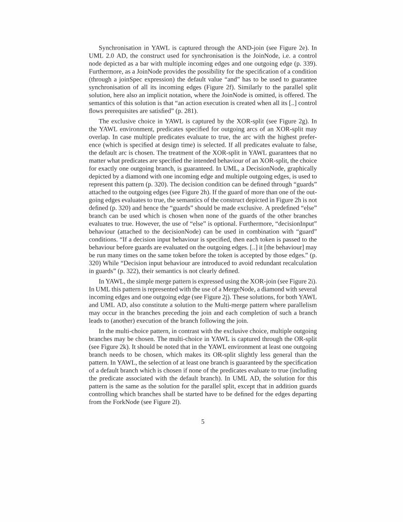
Solution in UML This pattern is captured in UML AD by the use of a fork and a set ofaccept signal actions, one preceeding each action in the choice. In addition, an interrupt-ible activity region encircling these signals is defined (see Figure 10). The semantics isthat the first signal received will enable and trigger the activity following it (followsfrom the definition of AcceptEventAction on p. 217) and at the same time disable therest of the activities included in the deferred choice by terminating all other remainingreceive signal actions in the region (follows from the definition of InterruptibleActivi-tyRegion on p. 336). This solution is identical to the solution proposed by White [13].
11
A
Signal 1
Signal 2 C
B
Fig. 10. Deferred choice (solution identical to this in [13])
In [5], where an evaluation of UML AD version 1.4 was presented, this pattern wascaptured using a “waiting state”. This solution is not applicable for UML AD version2.0 as the notion of state is not supported anymore.
3.7 Interleaved parallel routing
Description Several activities are executed in an arbitrary order: Each activity is exe-cuted, the order is decided at run-time, and no two activities are executed at the samemoment (i.e. no two activities are active for the same process instance at the same time).
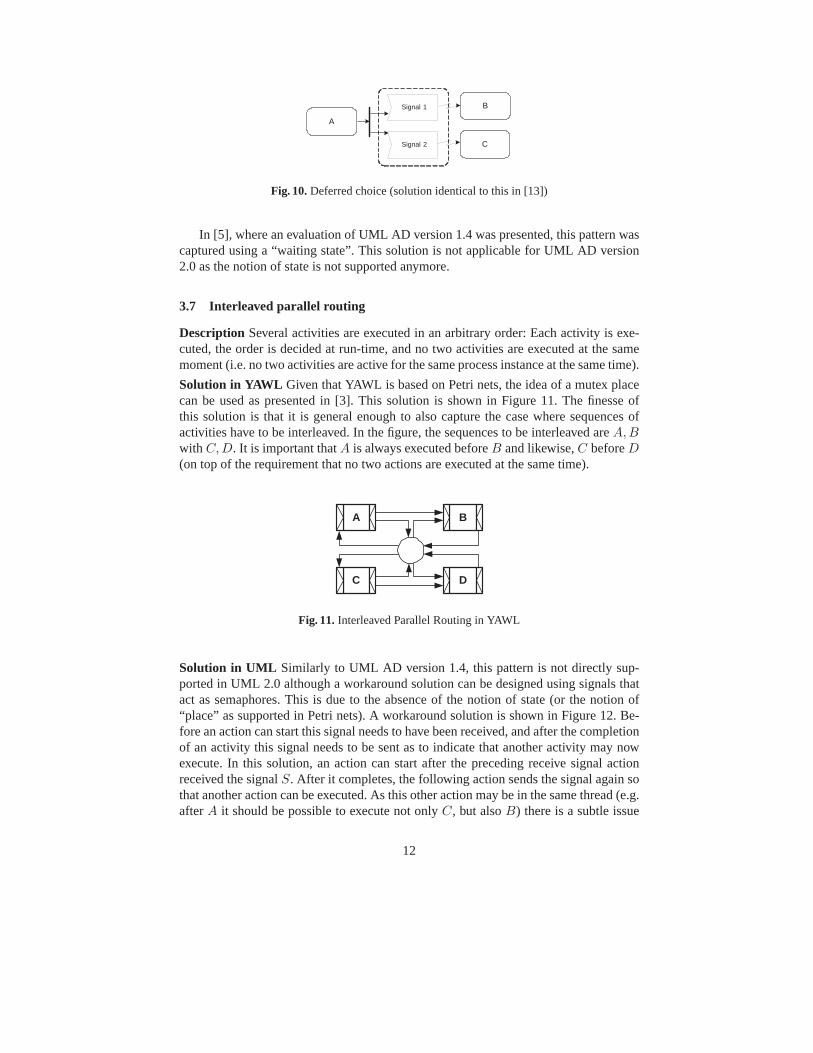
Solution in YAWL Given that YAWL is based on Petri nets, the idea of a mutex placecan be used as presented in [3]. This solution is shown in Figure 11. The finesse ofthis solution is that it is general enough to also capture the case where sequences ofactivities have to be interleaved. In the figure, the sequences to be interleaved are A,Bwith C,D. It is important that A is always executed before B and likewise, C before D(on top of the requirement that no two actions are executed at the same time).
A B
DC
Fig. 11. Interleaved Parallel Routing in YAWL
Solution in UML Similarly to UML AD version 1.4, this pattern is not directly sup-ported in UML 2.0 although a workaround solution can be designed using signals thatact as semaphores. This is due to the absence of the notion of state (or the notion of“place” as supported in Petri nets). A workaround solution is shown in Figure 12. Be-fore an action can start this signal needs to have been received, and after the completionof an activity this signal needs to be sent as to indicate that another activity may nowexecute. In this solution, an action can start after the preceding receive signal actionreceived the signal S. After it completes, the following action sends the signal again sothat another action can be executed. As this other action may be in the same thread (e.g.after A it should be possible to execute not only C, but also B) there is a subtle issue
12

of avoiding that an action of another thread will always “grab” the signal. This wouldoccur if the send and the receive signals were put in sequence, rather than in parallel,after completion of an activity, for activities not last in a thread. The solution presentedin Figure 12 assumes that 1) a signal can be sent from an action in a flow to an action inthe same flow, 2) even though there may be multiple receivers ready to receive a signalonly one of them will actually consume it (this is supported by the statement “[..] onlyone action accepts a given event, even if the event would satisfy multiple concurrentlyexecuting actions.”, p. 217), 3) subthreads of a flow really execute in parallel, and 4)a signal can be sent before anyone is ready to receive it (this is the case as signals arestored in the objects associated with send/receive signal actions).
A
C
B
D
Signal S
Signal S
Signal SSignal S
Signal S
Signal S
Signal S
Signal S Signal S
Fig. 12. Interleaved Parallel Routing
The two solutions presented by White [13] are not considered to be satisfactory. Thefirst solution models the pattern by putting a verbal constraint on a couple of parallelactivities stating that they are not to be run in parallel. The second solution explicitlyorders the threads involved, which is too strong an interpretation of the pattern. Forinstance, if as earlier the sequences A,B and C,D have to be interleaved and the exe-cution starts with A, White’s solution would restrict the execution order to A,B,C,D,while according to the pattern (and as demonstrated in Figure 11) execution ordersA,C,B,D and A,C,D,B should also be possible.
3.8 Milestone
Description A given activity can only be enabled if a certain milestone has been reachedwhich has not yet expired. A milestone is defined as a point in the process where a givenactivity has finished and an activity following it has not yet started.
Solution in YAWL YAWL directly supports the milestone pattern as it is based on Petrinets and therefore it can exploit the notion of state. A milestone can be realised throughthe use of arcs back and forth to a condition (which corresponds to the notion of placein Petri nets) testing whether a thread has reached a certain state.
Solution in UML There is no direct support for the milestone in UML AD as theconcept of state is not directly supported. A workaround can be devised with the useof signals, see Figure 13. In the solution depicted in this figure, there is a race afterthe completion of A between continuing B, which has to await the receipt of a signal(Signal 1) to indicate that continuation of the thread is appropriate, and performingsome other activity C. Activity C can only be performed after A has completed and
13

before B has started. This is achieved by sending a signal (Signal 2) which triggersanother signal (Signal 3) if indeed the other thread is in the correct state. If it is allowedto execute, then after completion, C issues a signal (Signal 4) indicating this.
A
Signal 1
Signal 2
B
Signal 3 C
...
...
...Signal 2
Signal 3
Signal 4
Signal 4
...
Fig. 13. Milestone
While workarounds exist for the state-based patterns, it is clear that mimicking theconcept of a place as it exists in Petri nets through the use of signals may add a lot ofcomplexity and could lead to models that are significantly less comprehensible.
The solution proposed by White [13] does not capture this pattern, as it does notmodel the expiration of the milestone. According to his solution an activity which po-tentially can be executed at a certain milestone, is always executed.
3.9 Cancellation
There are two cancellation patterns: cancel activity and cancel case. As their semanticsis straightforward we immediately focus on their solutions in YAWL and UML AD.
Solution in YAWL In Figure 14a execution of task B implies cancellation of task A,as this task is in the cancellation set of task B. In fact, any region can be chosen forcancellation so cancellation sets allow for cancellation of a single task, a whole case,and anything in between.
Solution in UML In UML AD, the cancel activity pattern can be captured as shownin Figure 14b. In this solution an interruptable region is used where apart from activityA there is an AcceptEventAction ready to accept a signal indicating that A should becancelled. If such a signal is received during the execution of activity A, and as an“interrupting edge” is used, everything in the region (in this case only activity A) willbe cancelled (p. 337). The solution in Figure 14b is inspired by Figure 260 on p. 338 ofthe UML specification [9]. It is also identical to the solution presented by White [13].Note that due to the statement “If an AcceptEventAction has no incoming edges, thenthe action starts when the containing activity or structured node6 does.” (p. 217) noincoming edge is used for the cancellation event.
In UML AD, the cancel case pattern is captured through the ActivityFinal node: “Atoken reaching an activity final node aborts all flows in the containing activity, that isthe activity is terminated, and the token is destroyed.” (p. 298). White [13] offers two
6 The interruptible region in our case.
14

solutions, one along the lines of the approach to cancel activity (by making the processto be cancelled an activity and running it in parallel with the cancellation event) and theother one using the ActivityFinal node.
a) Cancel Activity (and Cancel Case) in YAWL
A
Cancel A
A
B
b) Cancel Activity in UML AD
Fig. 14. Cancellation Concepts in YAWL and UML AD
4 Workflow Data Patterns in UML2.0 AD
Recent extensions [11] to the workflow patterns initiative have focussed on identify-ing and defining generic constructs that occur in the the data perspective of workflowsystems. In total forty data patterns have been delineated in five distinct groups:
– Data visibility — relating to the manner in which data elements are defined andcan be viewed and utilised by various components of a workflow process.
– Internal data interaction — focussing on the manner in which data is communi-cated between active elements within a workflow.
– External data interaction — focussing on the manner in which data is communi-cated between an active element within a workflow and processes, interfaces anddata repositories in the external operating environment.
– Data transfer — which consider the means by which the actual transfer of dataelements occurs between workflow components and describe the various mecha-nisms by which data elements can be passed across the interface of a workflowcomponent.
– Data-based routing — which characterise the manner in which data elements caninfluence the operation of other aspects of the workflow, particularly the controlflow perspective.
In this section, an analysis of UML version 2.0 AD is presented in the context of thedata patterns as described in [11].
4.1 Data visibility patterns
Data visibility patterns seek to characterise the various ways in which data elementscan be defined and utilised within the context of a workflow engine. In general, this isdetermined by the main construct to which the data element is bound as this implies aparticular scope in which the data element is visible and capable of being utilised.
There are eight patterns which relate to data visibility:
15

– Task data (pattern 1) – where data elements are defined by tasks and are only ac-cessible in the context of individual execution instances of the task.
– Block data (pattern 2) – where data elements are defined by block tasks (i.e. taskswhich can be described in terms of a corresponding sub-workflow decomposition)such that they are accessible to all of the components within the sub-workflow.
– Scope data (pattern 3) – where data elements can be defined and bound to a subsetof the tasks in a process definition.
– Folder data (pattern 4) – where data elements can be defined and bound to a subsetof the tasks in a process definition but are accessible to all instances of those tasksregardless of the case to which they correspond.
– Multiple instance data (pattern 5) – where data elements can be defined which arespecific to a single execution instance of a task (where the task is able to be executedmultiple times).
– Case data (pattern 6) – where data elements can be defined which are specific to aprocess instance or case of a workflow. They can be accessed by all components ofthe workflow during the execution of the case.
– Workflow data (pattern 7) – where data elements can be defined in such a way thatthey are accessible to all components in all cases.
– Environment data (pattern 8) – which describes the situation where data elementsdefined in the operational environment in which the workflow is sited can be ac-cessed within the workflow system.
In the case of UML 2.0 AD, there is support for several of these patterns. The smallestoperational unit in the context of these diagrams is the action. These correspond to thenotion of a workflow task and although the notion of task data is not directly supported,there is indirect support in the situation where a local action language is utilised whichprovides action-specific variables (see [9], p. 282-3).
Activities serve as the main grouping mechanism in UML 2.0 AD and they havesimilar characteristics to the block construct in workflow process definitions. The blockdata pattern is directly supported through parameters to activities (see [9], p. 304) whichare accessible to all activity components. The concept of attributes (see [9], p. 289) isalso provided which allows data elements to be defined which are scoped to a specificactivity.
Scope data and folder data are not supported. The ActivityGroup construct (see [9],p. 301) seems to offer something analogous however the semantics of the construct arenot defined.
Multiple instance data is directly provided for. There are three situations wheremultiple instances of a given task may arise:
1. Where a task is specifically designated as having multiple instances in the processmodel – this facility seems to be provided by the ExpansionKind construct (see [9],p. 324) where the parallel option is chosen forcing parallel execution.
2. Where a task can be triggered multiple times e.g. it is part of a loop. This situationis allowable in UML 2.0 AD (see [9], p. 287).
3. Where two tasks share the same decomposition. This is also supported in UML2.0 AD as each activity decomposition is distinct as it has a different set of tokenssupplied to it at initiation (see [9], p. 302).
16
Case data is not supported as there does not appear to be a notion of distinct executioninstances in UML 2.0 AD, rather all instances of a process model execution in the somecontext are differentiated by distinct sets of control and object tokens flowing throughthe diagram.
Workflow data is directly supported through data objects or ObjectNodes (see [9],p. 349) which are potentially accessible to all of the components in a UML 2.0 AD.
There does not appear to be the ability within a UML 2.0 AD to refer to data outsideof the context of the diagram, and hence environment data is not supported.
4.2 Internal data interaction patterns
Internal data interaction patterns deal with the various ways in which data elements canbe passed between components within a workflow process and how the characteristicsof the individual components can influence the manner in which the trafficking of dataelements occurs. There are six scenarios in which this may occur:
– Data elements flowing between task instances (pattern 9).– Data elements flowing from a block task to its decomposition or vice versa (patterns
10-11).– Data elements flowing to or from a multiple instance task instance (patterns 12-13).– Data elements flowing between cases (pattern 14).
Data interaction between tasks is directly supported in UML 2.0 AD by the ObjectNodeconstruct (see [9], p. 345) which is the standard means of communicating data elementsbetween activities.
Data interaction between block tasks and their decompositions has a similar analogyin UML 2.0 AD in the form of data passing to and from activities. The standard meansof doing this is via parameters (see [9], p. 304). Both the Data interaction block taskto sub-workflow and data interaction sub-workflow to block task patterns are directlysupported.
Data interaction to and from multiple instance tasks has a direct analogy in UML2.0 AD in the ExpansionRegion construct (see [9], p. 325) which allows nominatedregions of a process model to be executed multiple times in parallel (providing the Ex-pansionKind mode is set to parallel). Data passing into and out of the ExpansionRegionoccurs using ExpansionNodes which provide the ability to map distinct sections of theinput data set to specific execution instances and similarly completing instances canmap their output to a specific section of the output data set. Hence the Data interactionto and from multiple instance task patterns (12 and 13) are directly supported.
There is no notion of distinct execution cases in UML 2.0 ADs, hence the Datainteraction – case to case pattern (14) is not supported.
4.3 External data interaction patterns
External data interaction patterns identify situations where data passing occurs betweenthe workflow and the operating environment. They may involve data transfer betweena component of the workflow and an application, data store or interface that is externalto the workflow.
There are 12 external data interaction patterns, characterised by three dimensions:
17

– The type of workflow component – task, case or workflow – that is interacting withthe environment.
– Whether the interaction is push or pull-based– Whether the interaction is initiated by the workflow component or the environment.
Difficulties arise when examining UML 2.0 ADs in the context of this class of patternsas the UML approach assumes the Activity Diagram represents the complete universeof discourse and does not provide the ability to reference or interact with elements thatare external to it.
4.4 Data transfer patterns
Data transfer patterns focus on the manner in which the actual transfer of data elementsoccurs between one workflow component and another. They aim to capture the variousmechanisms by which data elements can be passed across the interface of a workflowcomponent.
There are seven distinct patterns in this category:
– Data transfer by value – incoming (pattern 27) – where incoming data elements toa workflow component are passed by value.
– Data transfer by value – outgoing (pattern 28) – where outgoing data elements froma workflow component are passed by value.
– Data transfer – copy in/copy out (pattern 29) – where a workflow component copiesthe values of data elements into its address space from some external source at com-mencement and copies them back to that source once it has completed execution.
– Data transfer by reference – without lock (pattern 30) – where data elements arecommunicated between workflow components by utilising a reference to the lo-cation of the data element in some mutually accessible location. No concurrencyrestrictions apply to the shared data element.
– Data transfer by reference – with lock (pattern 31) – is similar to pattern 30 exceptthat concurrency restrictions are implied with the receiving component receivingthe privilege of read-only or dedicated access to the data element.
– Data transformation – input (pattern 32) – where a transformation function is ap-plied to a data element prior to it being passed to a workflow component.
– Data transformation – output (pattern 33) – where a transformation function is ap-plied to a data element prior to it being passed from a workflow component.
In the context of UML 2.0 ADs, only three of these patterns are supported:
– Data transfer by reference – with lock is the standard means of passing data ele-ments into an activity as parameters. Because UML 2.0 ADs adopt a token-orientedapproach to data passing, these parameters – which typically relate to objects – areeffectively consumed at activity commencement and only become visible and ac-cessible to other activities once the specific activity to which they were passed hascompleted and returned them.
– Data transformation – both input and output – can be achieved through the Ob-jectFlow transformation behaviour (see [9], p. 345) which allows transformationfunctions to be applied to data tokens as they are passed along connecting edgesbetween activities.
18

4.5 Data-based routing patterns
Data-based routing patterns capture the various ways in which data elements can inter-act with other perspectives and influence the overall operation of the workflow.
There are seven patterns in this category:
– Task precondition – data existence (pattern 34) – where data-based preconditionscan be specified for tasks based on the presence of data elements at execution time.
– Task precondition – data value (pattern 35) – where data-based preconditions canbe specified for tasks based on the value of specific data elements at execution time.
– Task postcondition – data existence (pattern 36) – where data-based postconditionscan be specified for tasks based on the existence of data elements at execution time.
– Task postcondition – data value (pattern 37) – where data-based postconditions canbe specified for tasks based on the value of specific data elements at execution time.
– Event-based task trigger (pattern 38) – the ability for an external event to initiate atask.
– Data-based task trigger (pattern 39) – the ability to trigger a specific task when anexpression based on workflow data elements evaluates to true.
– Data-based routing (pattern 40) – the ability to alter the control flow within a work-flow case as a consequence of the value of data-based expressions.
The majority of these patterns are supported in UML 2.0 ADs. Both action and activityconstructs include local preconditions and postconditions based on logical expressions(which may include data elements) framed in OCL (see [9], p. 280 and 305). As a con-sequence, all of the task pre and postcondition patterns (34 - 37) are directly supported.
The AcceptEventAction construct (see [9], p. 217) provides direct support for theevent-based task triggering pattern. Similarly, there is also direct support for data-basedrouting via the DecisionNode construct and guard conditions on ActivityEdges (see [9],p. 319 and 293). Data-based task triggers are not directly implemented, however a sim-ilar (although somewhat more limited effect) can also be achieved through guards onActivityEdges.
5 Conclusion
Table 1 summarises the evaluation in terms of the control flow patterns. A ’+’ in thetable indicates direct support for the pattern (i.e. there is a construct in the language thatdirectly supports the pattern). The evaluation of UML 2.0 is contrasted with a previousevaluation of UML 1.47. Overall, UML 2.0 is a clear improvement over UML 1.4 interms of direct support for the control flow patterns. As regards the patterns that UML2.0 does not directly support we would like to make the following recommendations:
– Given the difficulties in supporting state-based patterns, most notably the inter-leaved parallel routing pattern and the milestone pattern, it may be worthwhile toprovide direct support for the notion of place as it exists in Petri nets. Petri netplaces capture the notion of “waiting state” in a much less restrictive way than “re-ceive signal actions” do. Similarly to YAWL, one could then choose to allow forimplicit places to avoid that places unnecessarily clutter up the diagram.
7 This evaluation is based on [5] and the table presented at www.workflowpatterns.com.
19

– UML AD currently does not support the creation of new instances of an activitywhile other instances of that activity are already running. This could be resolvedthrough extensions to the “expansion region” construct along the lines of the “mul-tiple instance” tasks in YAWL.
– Given the lack of support for the OR-join, a concept similar to the OR-join as itexists in YAWL could be added to UML AD.
Nr Pattern 2.0 1.4 Nr Pattern 2.0 1.4
1 Sequence + + 11 Implicit Termination + –2 Parallel Split + + 12 MI without Synchronization + –3 Synchronization + + 13 MI with a priori Design Time Knowledge + +4 Exclusive Choice + + 14 MI with a priori Runtime Knowledge + +5 Simple Merge + + 15 MI without a priori Runtime Knowledge – –6 Multi Choice + – 16 Deferred Choice + +7 Synchronizing Merge – – 17 Interleaved Parallel Routing – –8 Multi-Merge + – 18 Milestone – –9 Discriminator + – 19 Cancel Activity + +10 Arbitrary Cycles + – 20 Cancel Case + +
Table 1. Comparison of UML AD (version 2.0) and UML AD (version 1.4)
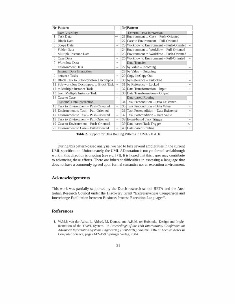
The data patterns evaluation is summarised in Table 5. The evaluation shows that thecontrol-flow and the data perspectives are well integrated. Pre/postconditions, triggersand routing are all supported. Furthermore, the following remarks can be made:
– There is no notion of cases in UML 2.0 ADs hence all data is effectively block-scoped by default and parallel threads of execution occur in the same data space.This could lead to some interesting situations when modelling highly data intensiveand/or highly concurrent processes.
– The use of ”tokens” as the fundamental underpinning for control and data flow in-troduces some subtle variations that do not exist in workflow systems (except thosebased on Petri-nets) - in particular data elements are truly consumed (and ceaseto exist) when they are passed to an activity for the duration of the activity. Thisalso makes it difficult to actually share a data element/object between concurrentactivities. On the other hand, it minimises concurrency problems.
– The token approach provides an effective basis for internal data interaction (andhence all patterns are ”+”). In particular, multiple instance data handling seems tobe supported for all three multiple instance situations: designated MI tasks, multiplytriggered tasks (loops) and block tasks with a common decomposition.
– There does not seem to be any ability to model things “outside of the model” i.e.in the external environment. Hence there is no real ability to support external datainteraction patterns. This may be addressed by using UML AD in conjunction withother diagrams such as UML interaction overview and sequence diagrams, but then,the relationships between these diagrams need to be carefully established.
20
Nr Pattern Nr Pattern
Data Visibility External Data Interaction1 Task Data +/– 21 Environment to Case – Push-Oriented –2 Block Data + 22 Case to Environment – Pull-Oriented –3 Scope Data – 23 Workflow to Environment – Push-Oriented –4 Folder Data – 24 Environment to Workflow – Pull-Oriented –5 Multiple Instance Data + 25 Environment to Workflow – Push-Oriented –6 Case Data – 26 Workflow to Environment – Pull-Oriented –7 Workflow Data + Data Transfer8 Environment Data – 27 by Value – Incoming –
Internal Data Interaction 28 by Value – Outgoing –9 between Tasks + 29 Copy In/Copy Out –10 Block Task to Sub-workflow Decompos. + 30 by Reference – Unlocked –11 Sub-workflow Decompos. to Block Task + 31 by Reference – Locked +12 to Multiple Instance Task + 32 Data Transformation – Input +13 from Multiple Instance Task + 33 Data Transformation – Output +14 Case to Case – Data-based Routing
External Data Interaction 34 Task Precondition – Data Existence +15 Task to Environment – Push-Oriented – 35 Task Precondition – Data Value +16 Environment to Task – Pull-Oriented – 36 Task Postcondition – Data Existence +17 Environment to Task – Push-Oriented – 37 Task Postcondition – Data Value +18 Task to Environment – Pull-Oriented – 38 Event-based Task Trigger +19 Case to Environment – Push-Oriented – 39 Data-based Task Trigger +/–20 Environment to Case – Pull-Oriented – 40 Data-based Routing +
Table 2. Support for Data Routing Patterns in UML 2.0 ADs
During this pattern-based analysis, we had to face several ambiguities in the currentUML specification. Unfortunately, the UML AD notation is not yet formalised althoughwork in this direction is ongoing (see e.g. [7]). It is hoped that this paper may contributeto advancing these efforts. There are inherent difficulties in assessing a language thatdoes not have a commonly agreed upon formal semantics nor an execution environment.
Acknowledgements
This work was partially supported by the Dutch research school BETA and the Aus-tralian Research Council under the Discovery Grant “Expressiveness Comparison andInterchange Facilitation between Business Process Execution Languages”.
References
1. W.M.P. van der Aalst, L. Aldred, M. Dumas, and A.H.M. ter Hofstede. Design and Imple-mentation of the YAWL System. In Proceedings of the 16th International Conference onAdvanced Information Systems Engineering (CAiSE’04), volume 3084 of Lecture Notes inComputer Science, pages 142–159. Springer Verlag, 2004.
21

2. W.M.P. van der Aalst and A.H.M. ter Hofstede. YAWL: Yet Another Workflow Language.Accepted for publication in Information Systems, and also available as QUT Technical reportFIT-TR-2003-04, Queensland University of Technology, Brisbane, Australia, 2003.
3. W.M.P. van der Aalst, A.H.M. ter Hofstede, B. Kiepuszewski, and A.P. Barros. WorkflowPatterns. Distributed and Parallel Databases, 14(1):5–51, 2003.
4. F. Casati, S. Ceri, B. Pernici, and G. Pozzi. Conceptual Modelling of Workflows. InM.P. Papazoglou, editor, Proceedings of the 14th International Object-Oriented and Entity-Relationship Modelling Conference (OOER), volume 1021 of Lecture Notes in ComputerScience, pages 341–354, Gold Coast, Australia, December 1998. Springer.
5. M. Dumas and A. ter Hofstede. UML activity diagrams as a workflow specification lan-guage. In M. Gogolla and C. Kobryn, editors, Proc. of the 4th Int. Conf. on the UnifiedModeling Language (UML01), volume 2185 of Lecture Notes in Computer Science, pages76–90. Springer Verlag, Oct 01.
6. P. Green and M. Rosemann. Applying Ontologies to Business and Systems Modeling Tech-niques and Perspectives: Lessons Learned. Journal of Database Management, 15(2):105–117, 2004.
7. H. Storrle. Semantics of Control-Flow in UML 2.0 Activities. In IEEE Symposium on VisualLanguages and Human-Centric Computing (VL/HCC’04), pages 235–242, September 2004.
8. Ja-Hee Kim and C. Huemer. Analysis, Transformation, and Improvements of ebXML Chore-ographies Based on Workflow Patterns. In Proceedings of the OTM Confederated Interna-tional Conferences (CoopIS, DOA, and ODBASE), volume 3290–3291 of Lecture Notes inComputer Science, pages 66–84, Agia Napa, Cyprus, October 2004.
9. OMG. UML 2.0 Superstructure Specification. OMG Draft Adopted Specification, ptc/03-08-02, August 2003. http://www.omg.org/cgi-bin/doc?ptc/2003-08-02.
10. A.L. Opdahl and B. Henderson-Sellers. Ontological Evaluation of the UML Using theBunge-Wand-Weber Model. Software and System Modeling, 1(1):43–67, 2002.
11. N. Russell, A.H.M. ter Hofstede, D. Edmond, and W.M.P. van der Aalst. Workflow DataPatterns. QUT Technical report, FIT-TR-2004-01, Queensland University of Technology,Brisbane, Australia, 2004.
12. WfMC. Workflow Management Coalition Terminology & Glossary, Document NumberWFMC-TC-1011, Document Status - Issue 3.0. Technical report, Workflow ManagementCoalition, Brussels, Belgium, February 1999.
13. S. White. Process Modeling Notations and Workflow Patterns. In L. Fischer, editor, WorkflowHandbook 2004, pages 265–294. Future Strategies Inc., Lighthouse Point, FL, USA, 2004.
14. P. Wohed, W.M.P. van der Aalst, M. Dumas, and A.H.M. ter Hofstede. Analysis of Web Ser-vices Composition Languages: The Case of BPEL4WS. In 22nd International Conferenceon Conceptual Modeling (ER 2003), volume 2813 of Lecture Notes in Computer Science,pages 200–215. Springer Verlag, 2003.
15. M.T. Wynn, D. Edmond, A.H.M. ter Hofstede, and W.M.P. van der Aalst. Achieving aGeneral, Formal and Decidable Approach to the OR-join in Workflow using Reset nets.QUT Technical report, FIT-TR-2004-02, Queensland University of Technology, Brisbane,Australia, 2004.
22