pattern centric opc flow: a special ret flow with fast ... centric opc flow_a... · pattern centric...
TRANSCRIPT
Pattern Centric OPC Flow: a Special RET Flow with Fast Turn-Around-Time
Tom Wang *1, Joanne Wu2, Qingwei Liu1, Gary Zhang 2,
Benny Wang 1, Bo Su 2, Guojie Cheng 2 Semiconductor Manufacturing International Corp.1, Anchor Semiconductor 2,
Abstract
Low K1 photolithography process increases the complexity of RET applications in IC designs. As technology node shrinks, pattern density is much denser along with much smaller geometry dimensions. Model-based OPC (Optical Proximity Correction) and post-OPC verification require more complex models and through process window compensated approaches, which significantly increase computational burden. Both lithographical challenges and computational complexity associated with 45nm process and below create a need for advanced capabilities on commercial OPC tools. To answer those challenges, hardware-accelerated OPC solution made a debut to solve runtime bottleneck issues, but they came in with very expensive price tags. As today, there are no explorations on the linkage between design styles and layout pattern OPC reusability.
This paper introduces a new OPC flow with pattern-centric approach to leverage OPC knowledge of repeated design cells and patterns to achieve fast full chip OPC convergence, shorter cycle time, better OPC quality, and eventually lead to high manufacturing yields. In this paper, the main concepts of pattern-based OPC flow are demonstrated in 65nm customer memory designs. Pattern-based OPC is a natural extension of Anchor's pattern-centric approaches in DFM (Design for Manufacturing) domain.
Keywords: Pattern-based OPC, pattern-centric approach
Optical Microlithography XXI, edited by Harry J. Levinson, Mircea V. Dusa, Proc. of SPIE Vol. 6924, 69243V, (2008) · 0277-786X/08/$18 · doi: 10.1117/12.771617
Proc. of SPIE Vol. 6924 69243V-1
1. Introduction
It is now clear that exposure wavelength will stay at 193nm for 32nm, and even possibly 22nm technology nodes, more aggressive Optical Proximity Correction (OPC) and Resolution Enhancement Techniques (RETs) have enabled photomasks to scale at an incredible rate and will continue to do so. OPC has matured and improved to a level that lithographers have found ways to keep optical lithography as the workhorse of the industry rather than move to more expensive alternatives. Along the same line of such trending, more advanced techniques and requirements are on OPC methodology development. The workload of OPC correction mainly falls on polygon fragmentation, model simulation for edge movement, and multiple correction iterations for OPC convergence. As devices continue to shrink, more complicated and dense patterns packed inside the same die size. Therefore, more aggressive pattern simulations have to take consideration of process window, MEEF, image contrast, and other aspects. On the other hand, the sheer complexity of managing more transistors on a chip requires newer tools and databases. Computational burden of model-based OPC flow has increased tremendously due to complicated process model for describing more complicated proximity effect and longer OPC processing times for each polygon. There is an urgent need for a software solution which utilizes efficient methodology to process OPC correction based on the design space information, such as unique patterns and their percentage of reusability. A unique pattern is referred to be a target with its environment polygons within an optical diameter. The key idea is the reusability of the unique patterns’ OPC for a full chip to reduce overall OPC processing time as much as possible.
The framework of efficient OPC has to overcome two issues even in the current state-of-art OPC techniques and methodology. First, model-based OPC is an iterative process, full convergence to an optimal correction is not always guaranteed. There is ripple effect, which manifests itself as the same pattern gets different OPC correction due to OPC convergence issue. Tight CD variation control becomes hard to accomplish if there is ripple effect. Therefore, additional reliable post-OPC verification with rigorous treatment is necessary in order to detect potential failures before a design is sent to mask manufactures. Second, it is a well-known fact that a fully rigorous simulation at full chip level is very time and machine resource consuming as it is not practical.
This paper introduces a new OPC flow with pattern-centric approach to leverage OPC knowledge of repeated design cells and patterns to achieve fast full chip OPC convergence shorten cycle time, improve OPC quality along with lower cost of ownership (COO) compared to existing commercial OPC tools in today’s market. The new OPC flow, called Pattern-Based OPC (PBOPC) in this paper, differs significantly from the existing OPC flow with the advantages of detailed analysis of layout patterns
Proc. of SPIE Vol. 6924 69243V-2
Iayout Partition
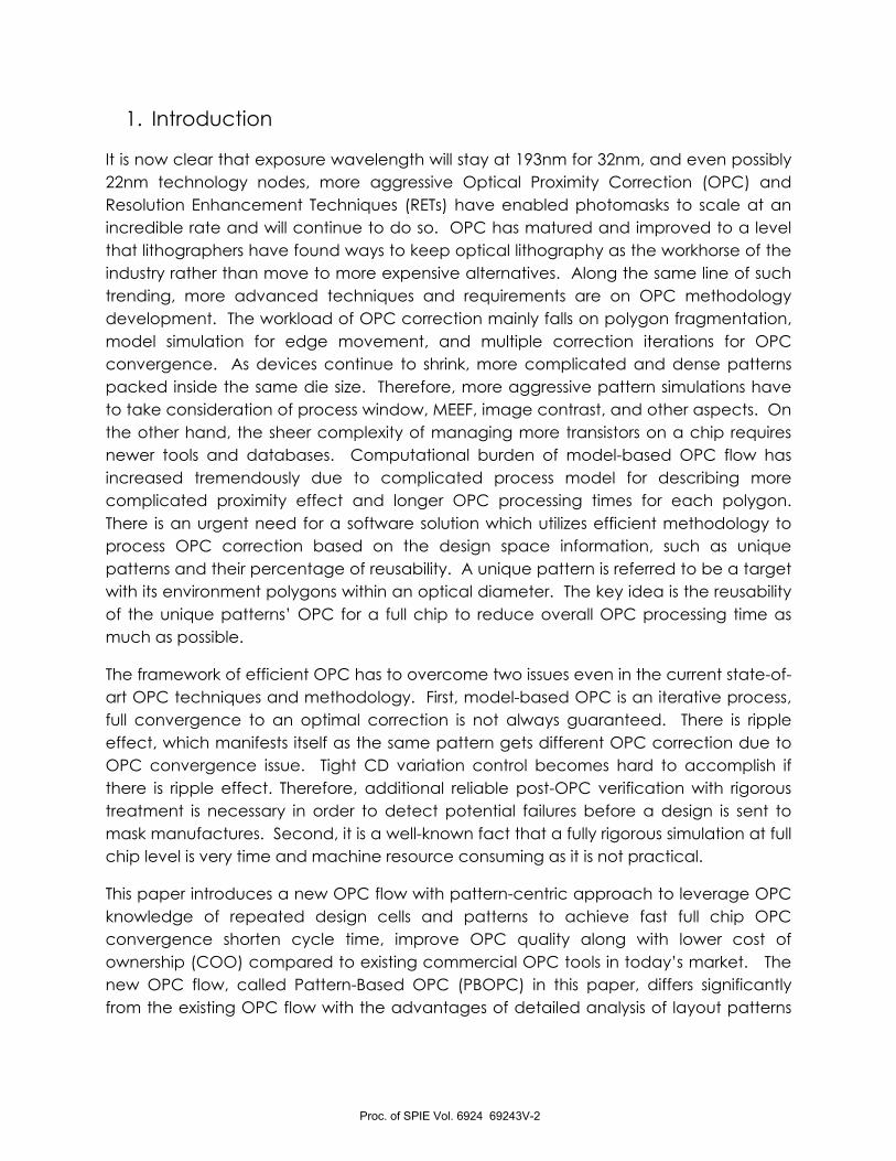
and their reusability to improve OPC performance efficiency. Figure 1 illustrates the main steps of pattern-centric OPC flow.
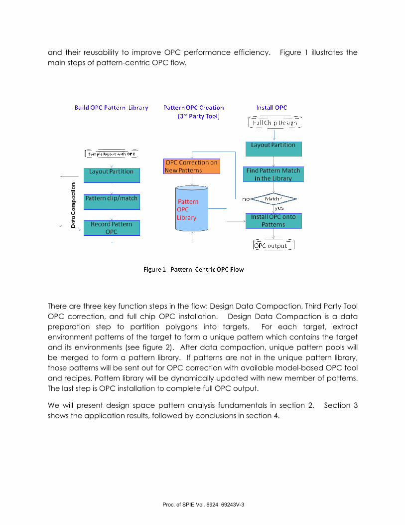
There are three key function steps in the flow: Design Data Compaction, Third Party Tool OPC correction, and full chip OPC installation. Design Data Compaction is a data preparation step to partition polygons into targets. For each target, extract environment patterns of the target to form a unique pattern which contains the target and its environments (see figure 2). After data compaction, unique pattern pools will be merged to form a pattern library. If patterns are not in the unique pattern library, those patterns will be sent out for OPC correction with available model-based OPC tool and recipes. Pattern library will be dynamically updated with new member of patterns. The last step is OPC installation to complete full OPC output.
We will present design space pattern analysis fundamentals in section 2. Section 3 shows the application results, followed by conclusions in section 4.
Proc. of SPIE Vol. 6924 69243V-3
Elipattern
User defined pattern range(typical 1-2 pm)
-rHI
Layout (yellow boxes are repeaters)
Figure 2 Target and its Patterns in a Layout
2. Design Space Pattern Centric Approach in PBOPC
The concepts behind pattern-centric OPC flow are straightforward. In PBOPC flow, OPC operation is performed on a pattern-by-pattern basis. If the same layout pattern exists in different cells of a full chip layout, this pattern’s post-OPC data can be re-used. The post-OPC results for the pattern can be saved into an OPC pattern library. OPC pattern library and pattern-matching are key operations in PBOPC flow. Anchor’s pattern-centric approach for pattern creation and matching are the main technical foundations. If the same pattern exists in a different layout design, the OPC results for the pattern can be retrieved from OPC pattern library and applied to the new design. PBOPC solution aims at reducing processing time in OPC mask synthesis flow. The most beneficial gain of this approach is expected for IC layout designs with heavily repeating patterns.
Proc. of SPIE Vol. 6924 69243V-4
An OPC pattern library consists of a list of layout patterns with pre-OPC and their corresponding post-OPC results managed by a text file describing the profile of the library and OPC models used for building the library. Before a pattern can be saved into OPC pattern library, input layout goes though the data compaction to create patterns with user definable size. Those patterns can be arranged in certain array and the tool sends the array to any 3rd party production-proven OPC tools for OPC correction. Customers can use their existing OPC treatment (models and recipes) to generate pattern OPC with expected accuracy. OPC pattern library serves as the center database for PBOPC flow. It interfaces with 3rd party OPC tools. A set of utility functions is available for the database management which includes query, sort, merge, prune, protection and version control, etc. OPC pattern installation step will assemble matched OPC pattern into a design, and a final output will include all features on the target layers, all features on the reference layers, and all patterns on the OPC layers.
2.1 OPC Accuracy
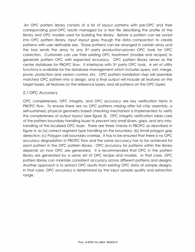
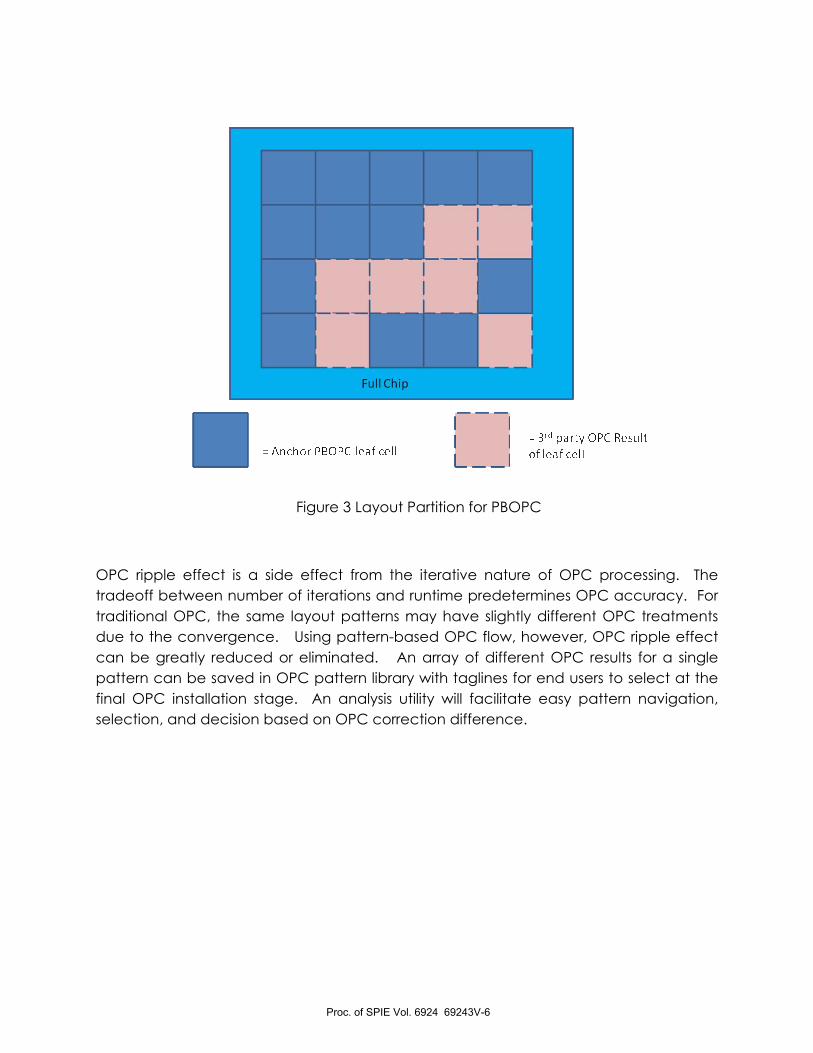
OPC completeness, OPC integrity, and OPC accuracy are key verification items in PBOPC flow. To ensure there are no OPC patterns missing after full chip assembly, a self-sustained, physical geometry based checking mechanism is implemented to verify the completeness of output layout (see figure 3). OPC integrity verification takes care of the pattern boundary handling issues to prevent any small slivers, gaps, and any miss-handling of the localized OPC layer. There are three checks in PBOPC as described in figure 4, as (a) correct segment type handling on the boundary; (b) Small polygon gap detection; (c) Polygon cell boundary overlap. It has to be ensured that there is no OPC accuracy degradation in PBOPC flow and the same accuracy has to be achieved for each pattern in the OPC pattern library. OPC accuracy for patterns within the library depends on how OPC are generated. It is recommended that OPC in the pattern library are generated by a same set of OPC recipe and models. In that case, OPC pattern library can maintain consistent accuracy across different patterns and designs. Another approach is to extract OPC results from existing OPC data of sample designs. In that case, OPC accuracy is determined by the input sample quality and extraction range.
Proc. of SPIE Vol. 6924 69243V-5
Full Chip
Figure 3 Layout Partition for PBOPC
OPC ripple effect is a side effect from the iterative nature of OPC processing. The tradeoff between number of iterations and runtime predetermines OPC accuracy. For traditional OPC, the same layout patterns may have slightly different OPC treatments due to the convergence. Using pattern-based OPC flow, however, OPC ripple effect can be greatly reduced or eliminated. An array of different OPC results for a single pattern can be saved in OPC pattern library with taglines for end users to select at the final OPC installation stage. An analysis utility will facilitate easy pattern navigation, selection, and decision based on OPC correction difference.
Proc. of SPIE Vol. 6924 69243V-6
Figure 4 OPC Integrity Verification in OPC Installation
2.2 OPC Performance
Proc. of SPIE Vol. 6924 69243V-7
Comparing to existing full chip model-based OPC flow, pattern-based OPC flow benefits from pattern re-use in multiple locations in a design and from one design to many other designs. OPC pattern library can be built up in incremental approach, or can be pre-built at leisure time to avoid mask tapeout period crunch.
Prior to PBOPC run, analysis utilities are provided to users to estimate pattern match rate for any given designs against existing OPC pattern library to determine if PBOPC flow is suitable. Analysis reports will help achieving the best accuracy and performance. The only added overhead in tapeout flow is I/O time between Anchor’s and the 3rd party OPC tool if a design has less than 100% OPC pattern coverage. An efficient integration between Anchor and 3rd party OPC tool will directly impact the performance of PBOPC flow. The best performance can be achieved with I/O file size compression and input/output design hierarchy optimization.
3. Experiment: Poly Layer Pattern Based OPC for 65nm Memory Devices
A Poly layer in 65nm memory block designs were used in our studies for pattern-based OPC flow performance and accuracy demonstration. Memory designs have highly repeated cells and patterns, they were chosen as suitable test vehicles for PBOPC. There are two reference layers used in the flow: one reference layer is SRAF, and the other is DIFF layer for gate reference purpose. Reference layers do involve in OPC pattern library generation, and are treated as primary polygons for pattern matching. Such approaches increase the complexity of OPC pattern library generation and reduces generic Poly layer pattern repetition rate in a memory design as we observed in this study. However, it is needed to maintain OPC accuracy without any induced degradations in pattern-centric OPC flow. The areas of SRAM in design A and in design B are 5746x5925um2 and 7090x7160um2, respectively. As explained in section 2, OPC pattern library was built up at leisure based on available designs in house. In this experiment, OPC pattern library was built up based on six full chip designs prior to the final run.
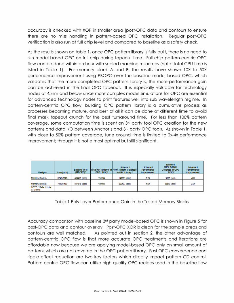
Two experiment schemes are explored in this paper to evaluate the relationship between percentages of pattern coverage in the OPC pattern library vs. total performance time for a given memory design. Scheme I is to use OPC pattern library with close to 50% pattern coverage to observe PBOPC runtime; scheme II is using 100% OPC pattern coverage to demonstrate pure pattern-based OPC pattern compaction, installation, and performance acceleration. Both performance and accuracy is compared to baseline OPC flow using 3rd party OPC models and recipes. OPC
Proc. of SPIE Vol. 6924 69243V-8
SnI SrsJ WthPIttU IrsUC TdI I Ptt II &A Ptt F{I34Maorq- C LtI&y OO
3.>; A Sd325 Ig'I: :$ I??S' UZ61 :$ 3 3I :$ S<
S .YSCI3 3C3?S :$ Ia*33 1�DIg :$ I )33'3 :$ gS<
30T3::S
accuracy is checked with XOR in smaller area (post-OPC data and contour) to ensure there are no miss handling in pattern-based OPC installation. Regular post-OPC verification is also run at full chip level and compared to baseline as a safety check.
As the results shown on table 1, once OPC pattern library is fully built, there is no need to run model based OPC on full chip during tapeout time. Full chip pattern-centric OPC flow can be done within an hour with scaled machine resources (note: total CPU time is listed in Table 1). For memory block A and B, the results have shown 10X to 50X performance improvement using PBOPC over the baseline model based OPC, which validates that the more completed OPC pattern library is, the more performance gain can be achieved in the final OPC tapeout. It is especially valuable for technology nodes at 45nm and below since more complex model simulations for OPC are essential for advanced technology nodes to print features well into sub wavelength regime. In pattern-centric OPC flow, building OPC pattern library is a cumulative process as processes becoming mature, and best of all it can be done at different time to avoid final mask tapeout crunch for the best turnaround time. For less than 100% pattern coverage, some computation time is spent on 3rd party tool OPC creation for the new patterns and data I/O between Anchor’s and 3rd party OPC tools. As shown in Table 1, with close to 50% pattern coverage, tune around time is limited to 2x-4x performance improvement; through it is not a most optimal but still significant.
Table 1 Poly Layer Performance Gain in the Tested Memory Blocks
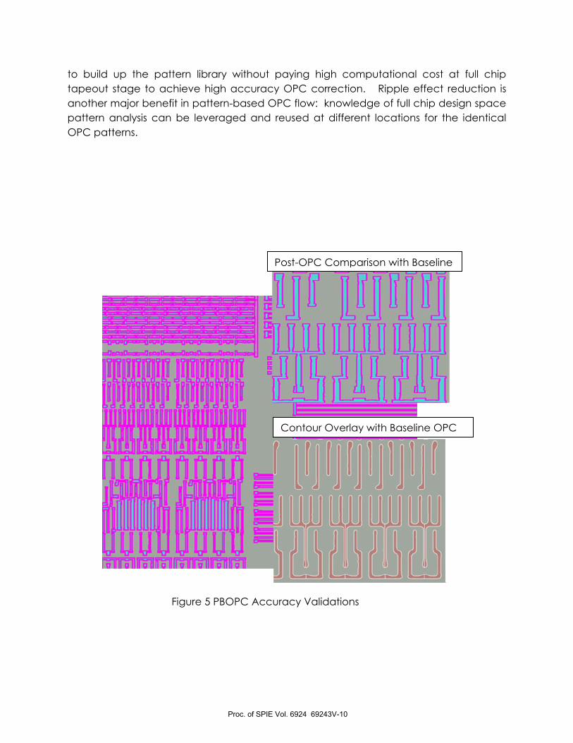
Accuracy comparison with baseline 3rd party model-based OPC is shown in Figure 5 for post-OPC data and contour overlay. Post-OPC XOR is clean for the sample areas and contours are well matched. As pointed out in section 2, the other advantage of pattern-centric OPC flow is that more accurate OPC treatments and iterations are affordable now because we are applying model-based OPC only on small amount of patterns which are not covered in the OPC pattern library. Fast OPC convergence and ripple effect reduction are two key factors which directly impact pattern CD control. Pattern centric OPC flow can utilize high quality OPC recipes used in the baseline flow
Proc. of SPIE Vol. 6924 69243V-9
iifrfrlnnni
.-p,,_. .hi.
n itriliii 11 huh 111111
J1IIJJ J1:JJ1 cli cli
101101110 DII 011101101110 lID UI
to build up the pattern library without paying high computational cost at full chip tapeout stage to achieve high accuracy OPC correction. Ripple effect reduction is another major benefit in pattern-based OPC flow: knowledge of full chip design space pattern analysis can be leveraged and reused at different locations for the identical OPC patterns.
Figure 5 PBOPC Accuracy Validations
Post-OPC Comparison with Baseline
Contour Overlay with Baseline OPC
Proc. of SPIE Vol. 6924 69243V-10
4. Conclusion
In this paper, we introduced a new OPC flow with Anchor’s proprietary pattern-centric approach to leverage OPC knowledge of repeated design patterns to achieve fast full chip OPC convergence, shorter cycle time, and tight CD control for memory devices. The tested results of performance gain in memory block demonstrated the valuation and benefits of pattern-based OPC flow with significant reduction of OPC turnaround time for Poly mask tapeout. It is a natural extension to apply the flow on other critical layers, such as metal 1 layer. Future work will focus on performance acceleration for logic devices at 45nm technology node and beyond.
Proc. of SPIE Vol. 6924 69243V-11