pbv floating flanged ball valves - primeva.com.au · 6400 series 4400 series 5400 series 6500...
TRANSCRIPT
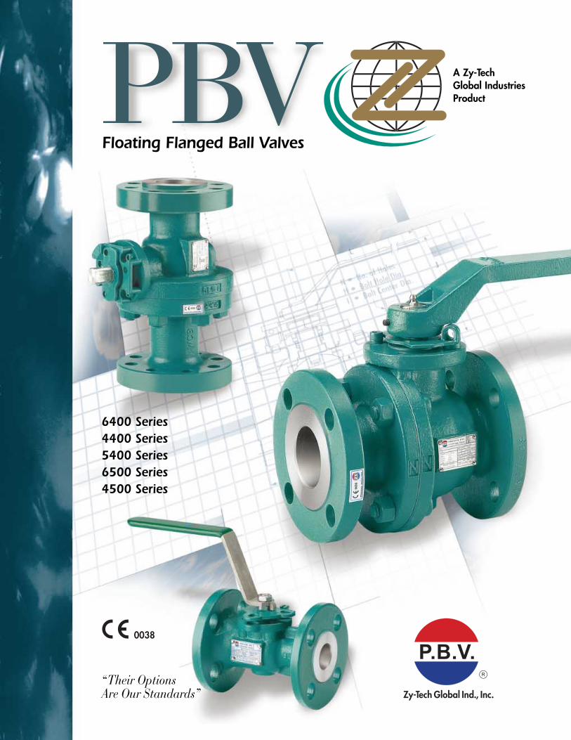
6400 Series4400 Series5400 Series6500 Series4500 Series
Floating Flanged Ball ValvesFloating Flanged Ball Valves
“Their OptionsAre Our Standards”
Floating Flanged Ball Valves
PBV A Zy-Tech Global Industries Product
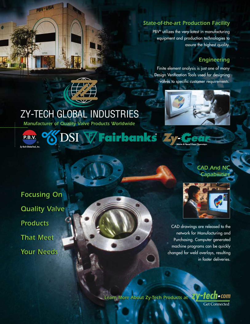
Finite element analysis is just one of many
Design Verification Tools used for designing
valves to specific customer requirements.
CAD drawings are released to the
network for Manufacturing and
Purchasing. Computer generated
machine programs can be quickly
changed for weld overlays, resulting
in faster deliveries.
PBV® utilizes the very latest in manufacturing
equipment and production technologies to
assure the highest quality.
WormWoW & Bevel Gear Operarar tors
State-of-the-art Production Facility
Engineering
CAD And NCCapabilities
Manufacturer of Quality Valve Products Worldwide
Learn More About Zy-Tech Products atLearn More About Zy-Tech Products at
Focusing On
Quality Valve
Products
That Meet
Your Needs
Focusing On
Quality Valve
Products
That Meet
Your Needs
ContentsContents
3
Product Range
PBV®-USA Floating Flanged Ball Valves
Product Range . . . . . . . . . . . . . . . . . . . . . . . . . . . . . . . . . . 3
Specifying Valve Figure Numbers . . . . . . . . . . . . . . . . . . . . . 4
Technical Data
Pressure Temperature Ratings . . . . . . . . . . . . . . . . . . . . . . . . 5Maximum Stem Break Torque . . . . . . . . . . . . . . . . . . . . . . . . 6Approximate Valve Weights . . . . . . . . . . . . . . . . . . . . . . . . . . 6Actuator Mounting DataSeries 4400, 5400 & 6400 Class 150, 300 & 600 . . . . . . . . . . 7Series 4500 & 6500 Class 150, 300 & 600 . . . . . . . . . . . . . . 8Flow Coefficient (Cv) . . . . . . . . . . . . . . . . . . . . . . . . . . . . . . 8Pressure Conversion . . . . . . . . . . . . . . . . . . . . . . . . . . . . . . . 8Certification of Quality and Design . . . . . . . . . . . . . . . . . . . . .9NACE Compliance . . . . . . . . . . . . . . . . . . . . . . . . . . . . . . . . 9Design Standards . . . . . . . . . . . . . . . . . . . . . . . . . . . . . . . . . 9Standard Features . . . . . . . . . . . . . . . . . . . . . . . . . . . . . . . 10Firesafe ISO Design . . . . . . . . . . . . . . . . . . . . . . . . . . . . . . 11
Series 4400 RP & 6400 FP 2 PieceStem Packing Ball ValvesStandard Design Features . . . . . . . . . . . . . . . . . . . . . . . 12, 14Dimensional Data, Series 6400 Class 150, 300 & 600 . . . . . . 13Dimensional Data, Series 4400 Class 150, 300 & 600 . . . . . . 15
Series 5400 RP UnibodyStem Packing Ball ValvesStandard Design Features . . . . . . . . . . . . . . . . . . . . . . . . . . 16Dimensional Data, Series 5400 Class 150 & 300 . . . . . . . . . 17
Series 4500 RP & 6500 FP 2 PieceO-Ring Stem Seal Ball ValvesStandard Design Features . . . . . . . . . . . . . . . . . . . . . . . . . . 18Dimensional Data, Series 4500 Class 150, 300 & 600 . . . . . . 18Dimensional Data, Series 6500 Class 150, 300 & 600 . . . . . . 19
Parts and MaterialsStem Packing Design . . . . . . . . . . . . . . . . . . . . . . . . . . 20, 21Stem O-Ring Design . . . . . . . . . . . . . . . . . . . . . . . . . . . . . . 22Maintenance and Repair Kits . . . . . . . . . . . . . . . . . . . . . . . 23Terms and Conditions . . . . . . . . . . . . . . . . . . . . . . Back Cover
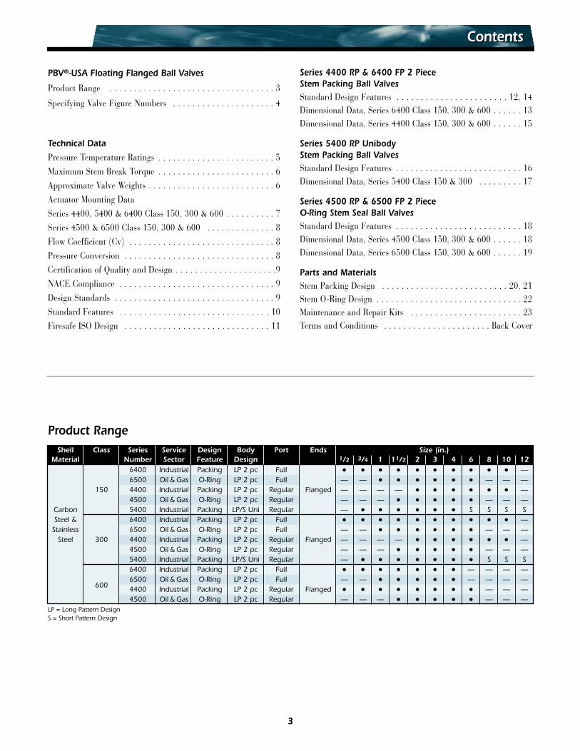
Shell Class Series Service Design Body Port Ends Size (in.)Material Number Sector Feature Design 1/2 3/4 1 11/2 2 3 4 6 8 10 12
6400 Industrial Packing LP 2 pc Full • • • • • • • • • • —6500 Oil & Gas O-Ring LP 2 pc Full — — • • • • • • — — —
150 4400 Industrial Packing LP 2 pc Regular Flanged — — — — • • • • • • —4500 Oil & Gas O-Ring LP 2 pc Regular — — — • • • • • — — —
Carbon 5400 Industrial Packing LP/S Uni Regular — • • • • • • S S S SSteel & 6400 Industrial Packing LP 2 pc Full • • • • • • • • • • —
Stainless 6500 Oil & Gas O-Ring LP 2 pc Full — — • • • • • • — — —Steel 300 4400 Industrial Packing LP 2 pc Regular Flanged — — — — • • • • • • —
4500 Oil & Gas O-Ring LP 2 pc Regular — — — • • • • • — — —5400 Industrial Packing LP/S Uni Regular — • • • • • • • S S S6400 Industrial Packing LP 2 pc Full • • • • • • • — — — —
6006500 Oil & Gas O-Ring LP 2 pc Full — — • • • • • — — — —4400 Industrial Packing LP 2 pc Regular Flanged • • • • • • • • — — —4500 Oil & Gas O-Ring LP 2 pc Regular — — — • • • • • — — —
LP = Long Pattern DesignS = Short Pattern Design
4
PBV®-USA Floating Flanged Ball Valve DesignsPBV®-USA Floating Flanged Ball Valve Designs
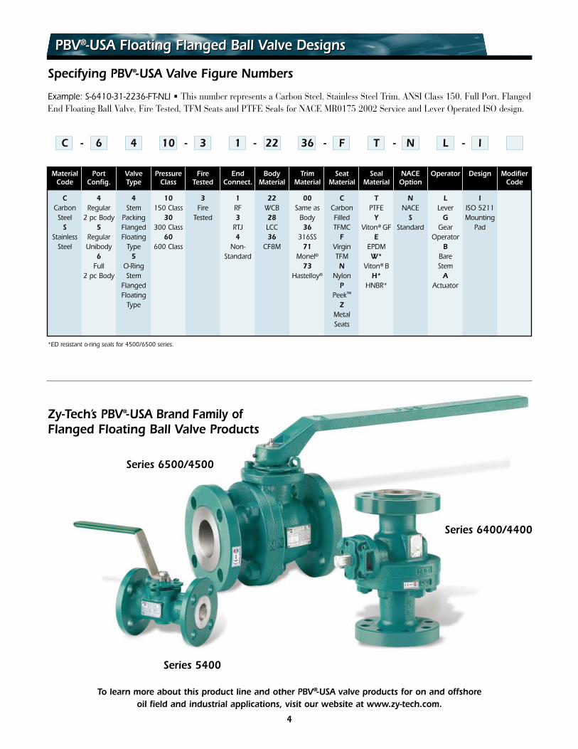
Specifying PBV®-USA Valve Figure Numbers
Example: S-6410-31-2236-FT-NLI • This number represents a Carbon Steel, Stainless Steel Trim, ANSI Class 150, Full Port, Flanged End Floating Ball Valve, Fire Tested, TFM Seats and PTFE Seals for NACE MR0175 2002 Service and Lever Operated ISO design.
C - 6 4 10 - 3 1 - 22 36 - F T - N L - I
Material Port Valve Pressure Fire End Body Trim Seat Seal NACE Operator Design ModifierCode Config. Type Class Tested Connect. Material Material Material Material Option Code
C 4 4 10 3 1 22 00 C T N L ICarbon Regular Stem 150 Class Fire RF WCB Same as Carbon PTFE NACE Lever ISO 5211
Steel 2 pc Body Packing 30 Tested 3 28 Body Filled Y S G MountingS 5 Flanged 300 Class RTJ LCC 36 TFMC Viton® GF Standard Gear Pad
Stainless Regular Floating 60 4 36 316SS F E OperatorSteel Unibody Type 600 Class Non- CF8M 71 Virgin EPDM B
6 5 Standard Monel® TFM W* BareFull O-Ring 73 N Viton® B Stem
2 pc Body Stem Hastelloy® Nylon H* AFlanged P HNBR* ActuatorFloating Peek™
Type ZMetalSeats
*ED resistant o-ring seals for 4500/6500 series.
Series 6500/4500
Series 5400
To learn more about this product line and other PBV®-USA valve products for on and offshoreoil field and industrial applications, visit our website at www.zy-tech.com.
Series 6400/4400
Zy-Tech’s PBV®-USA Brand Family ofFlanged Floating Ball Valve Products
5
Pressure Temperature RatingsPressure Temperature Ratings
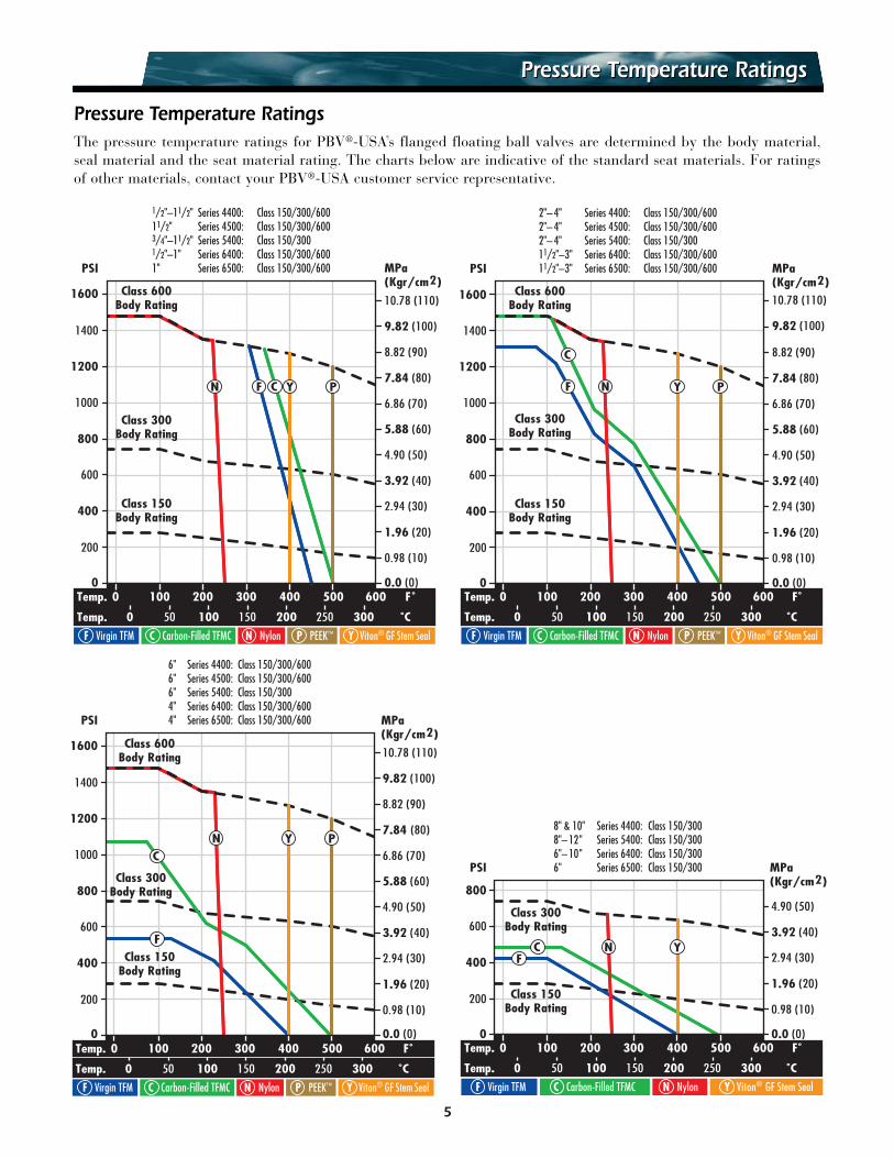
Pressure Temperature RatingsThe pressure temperature ratings for PBV®-USA’s flanged floating ball valves are determined by the body material,seal material and the seat material rating. The charts below are indicative of the standard seat materials. For ratingsof other materials, contact your PBV®-USA customer service representative.
PSI
1600
1400
1200
1000
800
600
400
200
0
6.86 (70)
5.88 (60)
4.90 (50)
3.92 (40)
2.94 (30)
1.96 (20)
0.98 (10)
0.0 (0)
MPa(Kgr/cm2)
10.78 (110)
9.82 (100)
8.82 (90)
7.84 (80)
Temp. 200 3001000 400 500 600 F˚
Temp. 50 1000 150 200 300250 ˚C
Class 600Body Rating
1/2"–11/2" Series 4400: Class 150/300/60011/2" Series 4500: Class 150/300/6003/4"–11/2" Series 5400: Class 150/3001/2"–1" Series 6400: Class 150/300/6001" Series 6500: Class 150/300/600
Class 150Body Rating
Class 300Body Rating
F Virgin TFM C Carbon-Filled TFMC N Nylon P PEEK™ Y Viton® GF Stem Seal
N F C Y P
PSI
1600
2"– 4" Series 4400: Class 150/300/6002"– 4" Series 4500: Class 150/300/6002"– 4" Series 5400: Class 150/30011/2"–3" Series 6400: Class 150/300/60011/2"–3" Series 6500: Class 150/300/600
1400
1200
1000
800
600
400
200
0
6.86 (70)
5.88 (60)
4.90 (50)
3.92 (40)
2.94 (30)
1.96 (20)
0.98 (10)
0.0 (0)
MPa(Kgr/cm2)10.78 (110)
9.82 (100)
8.82 (90)
7.84 (80)
Temp. 200 3001000 400 500 600 F˚
Temp. 50 1000 150 200 300250 ˚C
Class 600Body Rating
Class 150Body Rating
Class 300Body Rating
F Virgin TFM C Carbon-Filled TFMC N Nylon P PEEK™
PYN
C
F
Y Viton® GF Stem Seal
PSI
1600
6" Series 4400: Class 150/300/6006" Series 4500: Class 150/300/6006" Series 5400: Class 150/3004" Series 6400: Class 150/300/6004" Series 6500: Class 150/300/600
1400
1200
1000
800
600
400
200
0
6.86 (70)
5.88 (60)
4.90 (50)
3.92 (40)
2.94 (30)
1.96 (20)
0.98 (10)
0.0 (0)
MPa(Kgr/cm2)
10.78 (110)
9.82 (100)
8.82 (90)
7.84 (80)
Temp. 200 3001000 400 500 600 F˚
Temp. 50 1000 150 200 300250 ˚C
F Virgin TFM C Carbon-Filled TFMC N Nylon P PEEK™
F
C
Class 600Body Rating
Class 150Body Rating
Class 300Body Rating
N PY
Y Viton® GF Stem Seal
PSI
800
600
400
200
0
4.90 (50)
3.92 (40)
2.94 (30)
1.96 (20)
0.98 (10)
0.0 (0)
MPa(Kgr/cm2)
8" & 10" Series 4400: Class 150/3008"– 12" Series 5400: Class 150/3006"– 10" Series 6400: Class 150/3006" Series 6500: Class 150/300
Temp. 200 3001000 400 500 600 F˚
Temp. 50 1000 150 200 300250 ˚C
F Virgin TFM C Carbon-Filled TFMC N Nylon Y Viton® GF Stem Seal
FC N Y
Class 150Body Rating
Class 300Body Rating
00Press. 2000 400 600 800 1000 1200 1400 (PSI)
Torque(ft.lb.)
4000
3800
3600
3400
3200
3000
2800
2600
2400
2200
800
2000
600
1800
400
1600
200
1400
1200
1000
Torque(in.lb.)
26,000
14,000
12,000
10,000
8000
30,000
28,000
4000
6000
1100
900
700
500
2500
2300
300
240
220
200
180
160
140
120
100
80
60
40
20
17
7
19
18
340
320
300
280
260Cla
ss 15
0 Bo
dy R
atin
g
Class
300
Body
Rat
ing
Class
600
Body
Rat
ing
516
4
3
12
15
6
138
14
10
9
12
11
Maximum Stem Break Torque At Various PressuresMaximum Stem Break Torque At Various Pressures
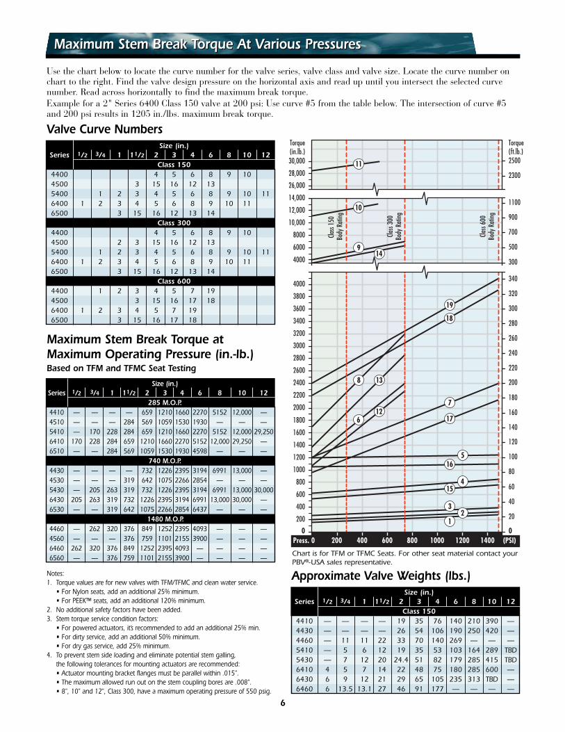
Use the chart below to locate the curve number for the valve series, valve class and valve size. Locate the curve number onchart to the right. Find the valve design pressure on the horizontal axis and read up until you intersect the selected curvenumber. Read across horizontally to find the maximum break torque.Example for a 2" Series 6400 Class 150 valve at 200 psi: Use curve #5 from the table below. The intersection of curve #5and 200 psi results in 1205 in./lbs. maximum break torque.
Size (in.)Series 1/2 3/4 1 11/2 2 3 4 6 8 10 12
Class 1504400 4 5 6 8 9 104500 3 15 16 12 135400 1 2 3 4 5 6 8 9 10 116400 1 2 3 4 5 6 8 9 10 116500 3 15 16 12 13 14
Class 3004400 4 5 6 8 9 104500 2 3 15 16 12 135400 1 2 3 4 5 6 8 9 10 116400 1 2 3 4 5 6 8 9 10 116500 3 15 16 12 13 14
Class 6004400 1 2 3 4 5 7 194500 3 15 16 17 186400 1 2 3 4 5 7 196500 3 15 16 17 18
Size (in.)Series 1/2 3/4 1 11/2 2 3 4 6 8 10 12
Class 1504410 — — — — 19 35 76 140 210 390 —4430 — — — — 26 54 106 190 250 420 —4460 — 11 11 22 33 70 140 269 — — —5410 — 5 6 12 19 35 53 103 164 289 TBD5430 — 7 12 20 24.4 51 82 179 285 415 TBD6410 4 5 7 14 22 48 75 180 285 600 —6430 6 9 12 21 29 65 105 235 313 TBD —6460 6 13.5 13.1 27 46 91 177 — — — —
Approximate Valve Weights (lbs.)
Valve Curve Numbers
Chart is for TFM or TFMC Seats. For other seat material contact yourPBV®-USA sales representative.
Notes:1. Torque values are for new valves with TFM/TFMC and clean water service.
• For Nylon seats, add an additional 25% minimum.• For PEEK™ seats, add an additional 120% minimum.
2. No additional safety factors have been added. 3. Stem torque service condition factors:
• For powered actuators, it’s recommended to add an additional 25% min.• For dirty service, add an additional 50% minimum.• For dry gas service, add 25% minimum.
4. To prevent stem side loading and eliminate potential stem galling, the following tolerances for mounting actuators are recommended:• Actuator mounting bracket flanges must be parallel within .015".• The maximum allowed run out on the stem coupling bores are .008".• 8", 10" and 12", Class 300, have a maximum operating pressure of 550 psig.
Maximum Stem Break Torque atMaximum Operating Pressure (in.-lb.)Based on TFM and TFMC Seat Testing
Size (in.)Series 1/2 3/4 1 11/2 2 3 4 6 8 10 12
285 M.O.P.4410 — — — — 659 1210 1660 2270 5152 12,000 —4510 — — — 284 569 1059 1530 1930 — — —5410 — 170 228 284 659 1210 1660 2270 5152 12,000 29,2506410 170 228 284 659 1210 1660 2270 5152 12,000 29,250 —6510 — — 284 569 1059 1530 1930 4598 — — —
740 M.O.P.4430 — — — — 732 1226 2395 3194 6991 13,000 —4530 — — — 319 642 1075 2266 2854 — — —5430 — 205 263 319 732 1226 2395 3194 6991 13,000 30,0006430 205 263 319 732 1226 2395 3194 6991 13,000 30,000 —6530 — — 319 642 1075 2266 2854 6437 — — —
1480 M.O.P.4460 — 262 320 376 849 1252 2395 4093 — — —4560 — — — 376 759 1101 2155 3900 — — —6460 262 320 376 849 1252 2395 4093 — — — —6560 — — 376 759 1101 2155 3900 — — — —
6
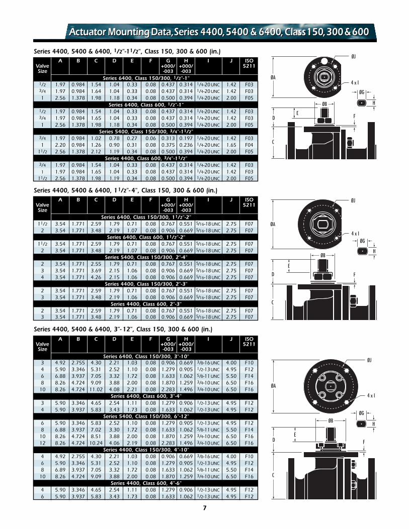
A B C D E F G H I J ISOValve +000/ +000/ 5211Size -003 -003
Series 6400, Class 150/300, 1/2"-1"1/2 1.97 0.984 1.54 1.04 0.33 0.08 0.437 0.314 1/4-20 UNC 1.42 F033/4 1.97 0.984 1.64 1.04 0.33 0.08 0.437 0.314 1/4-20 UNC 1.42 F031 2.56 1.378 1.98 1.18 0.34 0.08 0.500 0.394 1/4-20 UNC 2.00 F05
Series 6400, Class 600, 1/2"-1"1/2 1.97 0.984 1.54 1.04 0.33 0.08 0.437 0.314 1/4-20 UNC 1.42 F033/4 1.97 0.984 1.65 1.04 0.33 0.08 0.437 0.314 1/4-20 UNC 1.42 F031 2.56 1.378 1.98 1.18 0.34 0.08 0.500 0.394 1/4-20 UNC 2.00 F05
Series 5400, Class 150/300, 3/4"-11/2"3/4 1.97 0.984 1.02 0.78 0.27 0.06 0.313 0.197 1/4-20 UNC 1.42 F031 2.20 0.984 1.26 0.90 0.31 0.08 0.375 0.236 1/4-20 UNC 1.65 F04
11/2 2.56 1.378 2.12 1.19 0.34 0.08 0.500 0.394 1/4-20 UNC 2.00 F05Series 4400, Class 600, 3/4"-11/2"
3/4 1.97 0.984 1.54 1.04 0.33 0.08 0.437 0.314 1/4-20 UNC 1.42 F031 1.97 0.984 1.65 1.04 0.33 0.08 0.437 0.314 1/4-20 UNC 1.42 F03
11/2 2.56 1.378 1.98 1.19 0.34 0.08 0.500 0.394 1/4-20 UNC 2.00 F05
Series 4400, 5400 & 6400, 1/2"-11/2", Class 150, 300 & 600 (in.)
A B C D E F G H I J ISOValve +000/ +000/ 5211Size -003 -003
Series 6400, Class 150/300, 11/2"-2"11/2 3.54 1.771 2.59 1.79 0.71 0.08 0.767 0.551 5/16-18 UNC 2.75 F07
2 3.54 1.771 3.48 2.19 1.07 0.08 0.906 0.669 5/16-18 UNC 2.75 F07Series 6400, Class 600, 11/2"-2"
11/2 3.54 1.771 2.59 1.79 0.71 0.08 0.767 0.551 5/16-18 UNC 2.75 F072 3.54 1.771 3.48 2.19 1.07 0.08 0.906 0.669 5/16-18 UNC 2.75 F07
Series 5400, Class 150/300, 2"-4"2 3.54 1.771 2.55 1.79 0.71 0.08 0.767 0.551 5/16-18 UNC 2.75 F073 3.54 1.771 3.69 2.15 1.06 0.08 0.906 0.669 5/16-18 UNC 2.75 F074 3.54 1.771 4.26 2.15 1.06 0.08 0.906 0.669 5/16-18 UNC 2.75 F07
Series 4400, Class 150/300, 2"-3"2 3.54 1.771 2.59 1.79 0.71 0.08 0.767 0.551 5/16-18 UNC 2.75 F073 3.54 1.771 3.48 2.19 1.06 0.08 0.906 0.669 5/16-18 UNC 2.75 F07
Series 4400, Class 600, 2"-3"2 3.54 1.771 2.59 1.79 0.71 0.08 0.767 0.551 5/16-18 UNC 2.75 F073 3.54 1.771 3.48 2.19 1.06 0.08 0.906 0.669 5/16-18 UNC 2.75 F07
Series 4400, 5400 & 6400, 11/2"- 4", Class 150, 300 & 600 (in.)
Series 4400, 5400 & 6400, 3"- 12", Class 150, 300 & 600 (in.)A B C D E F G H I J ISO
Valve +000/ +000/ 5211Size -003 -003
Series 6400, Class 150/300, 3"-10"3 4.92 2.755 4.30 2.21 1.03 0.08 0.906 0.669 3/8-16 UNC 4.00 F104 5.90 3.346 5.31 2.52 1.10 0.08 1.279 0.905 1/2-13 UNC 4.95 F126 6.88 3.937 7.05 3.32 1.72 0.08 1.633 1.062 5/8-11 UNC 5.50 F148 8.26 4.724 9.09 3.88 2.00 0.08 1.870 1.259 3/4-10 UNC 6.50 F16
10 8.26 4.724 11.02 4.08 2.21 0.08 2.283 1.496 3/4-10 UNC 6.50 F16Series 6400, Class 600, 3"-4"
3 5.90 3.346 4.65 2.54 1.11 0.08 1.279 0.906 1/2-13 UNC 4.95 F124 5.90 3.937 5.83 3.43 1.73 0.08 1.633 1.062 1/2-13 UNC 4.95 F12
Series 5400, Class 150/300, 6"-12"6 5.90 3.346 5.83 2.52 1.10 0.08 1.279 0.905 1/2-13 UNC 4.95 F128 6.88 3.937 7.02 3.30 1.72 0.08 1.633 1.062 5/8-11 UNC 5.50 F14
10 8.26 4.724 8.51 3.88 2.00 0.08 1.870 1.259 3/4-10 UNC 6.50 F1612 8.26 4.724 10.24 4.06 2.19 0.08 2.283 1.496 3/4-10 UNC 6.50 F16
Series 4400, Class 150/300, 4"-10"4 4.92 2.755 4.30 2.21 1.03 0.08 0.906 0.669 3/8-16 UNC 4.00 F106 5.90 3.346 5.31 2.52 1.10 0.08 1.279 0.905 1/2-13 UNC 4.95 F128 6.89 3.937 7.05 3.32 1.72 0.08 1.633 1.062 5/8-11 UNC 5.50 F14
10 8.26 4.724 9.09 3.88 2.00 0.08 1.870 1.259 3/4-10 UNC 6.50 F16Series 4400, Class 600, 4"-6"
4 5.90 3.346 4.65 2.54 1.11 0.08 1.279 0.906 1/2-13 UNC 4.95 F126 5.90 3.937 5.83 3.43 1.73 0.08 1.633 1.062 1/2-13 UNC 4.95 F12
ØA
ØJ
4 x I
D
C
F
ØB
E
H
ØG
ØA
ØJ
4 x I
ØB
D
C
F
E
H
ØG
ØA
ØJ
4 x I
H
ØG
D
C
F
ØB
E
Actuator MountingData,Series 4400,5400 & 6400,Class150,300&600Actuator MountingData,Series 4400,5400 & 6400,Class150,300&600
7
8
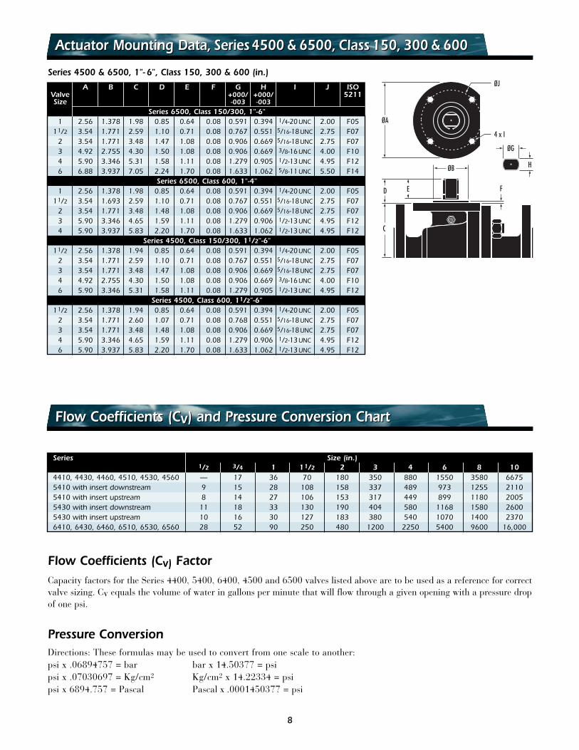
A B C D E F G H I J ISOValve +000/ +000/ 5211Size -003 -003
Series 6500, Class 150/300, 1"-6"1 2.56 1.378 1.98 0.85 0.64 0.08 0.591 0.394 1/4-20 UNC 2.00 F05
11/2 3.54 1.771 2.59 1.10 0.71 0.08 0.767 0.551 5/16-18 UNC 2.75 F072 3.54 1.771 3.48 1.47 1.08 0.08 0.906 0.669 5/16-18 UNC 2.75 F073 4.92 2.755 4.30 1.50 1.08 0.08 0.906 0.669 3/8-16 UNC 4.00 F104 5.90 3.346 5.31 1.58 1.11 0.08 1.279 0.905 1/2-13 UNC 4.95 F126 6.88 3.937 7.05 2.24 1.70 0.08 1.633 1.062 5/8-11 UNC 5.50 F14
Series 6500, Class 600, 1"-4"1 2.56 1.378 1.98 0.85 0.64 0.08 0.591 0.394 1/4-20 UNC 2.00 F05
11/2 3.54 1.693 2.59 1.10 0.71 0.08 0.767 0.551 5/16-18 UNC 2.75 F072 3.54 1.771 3.48 1.48 1.08 0.08 0.906 0.669 5/16-18 UNC 2.75 F073 5.90 3.346 4.65 1.59 1.11 0.08 1.279 0.906 1/2-13 UNC 4.95 F124 5.90 3.937 5.83 2.20 1.70 0.08 1.633 1.062 1/2-13 UNC 4.95 F12
Series 4500, Class 150/300, 11/2"-6"11/2 2.56 1.378 1.94 0.85 0.64 0.08 0.591 0.394 1/4-20 UNC 2.00 F05
2 3.54 1.771 2.59 1.10 0.71 0.08 0.767 0.551 5/16-18 UNC 2.75 F073 3.54 1.771 3.48 1.47 1.08 0.08 0.906 0.669 5/16-18 UNC 2.75 F074 4.92 2.755 4.30 1.50 1.08 0.08 0.906 0.669 3/8-16 UNC 4.00 F106 5.90 3.346 5.31 1.58 1.11 0.08 1.279 0.905 1/2-13 UNC 4.95 F12
Series 4500, Class 600, 11/2"-6"11/2 2.56 1.378 1.94 0.85 0.64 0.08 0.591 0.394 1/4-20 UNC 2.00 F05
2 3.54 1.771 2.60 1.07 0.71 0.08 0.768 0.551 5/16-18 UNC 2.75 F073 3.54 1.771 3.48 1.48 1.08 0.08 0.906 0.669 5/16-18 UNC 2.75 F074 5.90 3.346 4.65 1.59 1.11 0.08 1.279 0.906 1/2-13 UNC 4.95 F126 5.90 3.937 5.83 2.20 1.70 0.08 1.633 1.062 1/2-13 UNC 4.95 F12
Series 4500 & 6500, 1"- 6", Class 150, 300 & 600 (in.)
D
C
ØA
ØJ
4 x I
F
ØB H
ØG
E
Actuator Mounting Data, Series4500 & 6500, Class 150, 300 & 600Actuator Mounting Data, Series4500 & 6500, Class 150, 300 & 600
Flow Coefficients (Cv) and Pressure Conversion ChartFlow Coefficients (Cv) and Pressure Conversion Chart
Series Size (in.)1/2 3/4 1 11/2 2 3 4 6 8 10
4410, 4430, 4460, 4510, 4530, 4560 — 17 36 70 180 350 880 1550 3580 66755410 with insert downstream 9 15 28 108 158 337 489 973 1255 21105410 with insert upstream 8 14 27 106 153 317 449 899 1180 20055430 with insert downstream 11 18 33 130 190 404 580 1168 1580 26005430 with insert upstream 10 16 30 127 183 380 540 1070 1400 23706410, 6430, 6460, 6510, 6530, 6560 28 52 90 250 480 1200 2250 5400 9600 16,000
Pressure ConversionDirections: These formulas may be used to convert from one scale to another:psi x .06894757 = bar bar x 14.50377 = psipsi x .07030697 = Kg/cm2 Kg/cm2 x 14.22334 = psipsi x 6894.757 = Pascal Pascal x .0001450377 = psi
Flow Coefficients (Cv) FactorCapacity factors for the Series 4400, 5400, 6400, 4500 and 6500 valves listed above are to be used as a reference for correctvalve sizing. Cv equals the volume of water in gallons per minute that will flow through a given opening with a pressure dropof one psi.
9
ComplianceCompliance
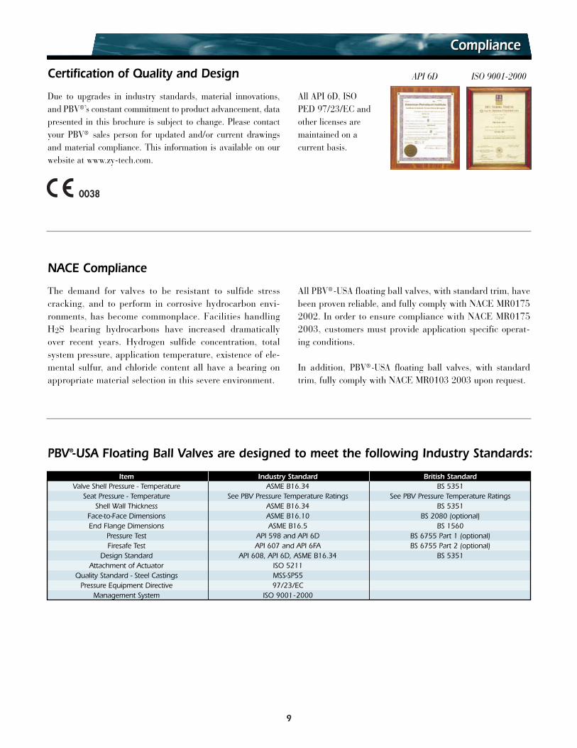
Due to upgrades in industry standards, material innovations,and PBV®’s constant commitment to product advancement, datapresented in this brochure is subject to change. Please contactyour PBV® sales person for updated and/or current drawingsand material compliance. This information is available on ourwebsite at www.zy-tech.com.
All API 6D, ISO PED 97/23/EC andother licenses aremaintained on a current basis.
ISO 9001-2000Certification of Quality and Design API 6D
NACE Compliance
The demand for valves to be resistant to sulfide stresscracking, and to perform in corrosive hydrocarbon envi-ronments, has become commonplace. Facilities handlingH2S bearing hydrocarbons have increased dramaticallyover recent years. Hydrogen sulfide concentration, totalsystem pressure, application temperature, existence of ele-mental sulfur, and chloride content all have a bearing onappropriate material selection in this severe environment.
All PBV® -USA floating ball valves, with standard trim, havebeen proven reliable, and fully comply with NACE MR01752002. In order to ensure compliance with NACE MR01752003, customers must provide application specific operat-ing conditions.
In addition, PBV®-USA floating ball valves, with standardtrim, fully comply with NACE MR0103 2003 upon request.
PBV®-USA Floating Ball Valves are designed to meet the following Industry Standards:
Item Industry Standard British StandardValve Shell Pressure - Temperature ASME B16.34 BS 5351
Seat Pressure - Temperature See PBV Pressure Temperature Ratings See PBV Pressure Temperature RatingsShell Wall Thickness ASME B16.34 BS 5351
Face-to-Face Dimensions ASME B16.10 BS 2080 (optional)End Flange Dimensions ASME B16.5 BS 1560
Pressure Test API 598 and API 6D BS 6755 Part 1 (optional)Firesafe Test API 607 and API 6FA BS 6755 Part 2 (optional)
Design Standard API 608, API 6D, ASME B16.34 BS 5351Attachment of Actuator ISO 5211
Quality Standard - Steel Castings MSS-SP55Pressure Equipment Directive 97/23/EC
Management System ISO 9001-2000
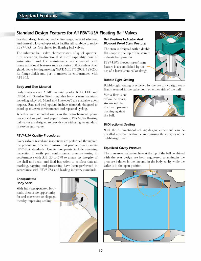
CLOSEOPEN
Standard Design Features for All PBV®-USA Floating Ball ValvesStandard design features, product line range, material selection,and centrally located operations facility all combine to makePBV®-USA the first choice for floating ball valves.
The inherent ball valve characteristics of quick quarter-turn operation, bi-directional shut-off capability, ease ofautomation, and low maintenance are enhanced withmany additional features such as Series 300 Stainless Steelgland, heavy bolting meeting NACE MR0175 2002, 125-250Ra flange finish and port diameters in conformance withAPI 608.
Body and Trim Material
Body materials are ASME material grades WCB, LCC andCF8M, with Stainless Steel trim; other body or trim materials,including Alloy 20, Monel and Hastelloy®, are available uponrequest. Seat and seal options include materials designed tostand up to severe environments and repeated cycling.
Whether your intended use is in the petrochemical, phar-maceutical or pulp and paper industry, PBV®-USA floatingball valves are designed to provide you with a higher standardin service and value.
PBV®-USA Quality Procedures
Every valve is tested and inspections are performed throughoutthe production process to insure that product quality meetsPBV®-USA standards. Quality holdpoints include receivinginspection to verify part conformance, pressure testing inconformance with API 6D or 598 to assure the integrity ofthe shell and seals, and final inspection to confirm that allmarking, tagging and processing have been performed inaccordance with PBV®-USA and leading industry standards.
EncapsulatedBody Seals
With fully encapsulated bodyseals, there is no opportunityfor seal movement or slippage,thereby improving sealing.
Ball Position Indicator AndBlowout Proof Stem Features
The stem is designed with a doubleflat shape at the top of the stem toindicate ball position.
PBV®-USA’s blowout proof stemfeature is accomplished by theuse of a lower stem collar design.
Bubble-Tight Sealing
Bubble-tight sealing is achieved by the use of two rigid seatsfirmly secured in the valve body on either side of the ball.
Media flow is cutoff on the down-stream side byupstream pressurepushing againstthe ball.
Bi-Directional Sealing
With the bi-directional sealing design, either end can beinstalled upstream without compromising the integrity of thebubble-tight seal.
Equalized Cavity Pressure
The pressure equalization hole at the top of the ball combinedwith the seat design are both engineered to maintain thepressure balance in the line and in the body cavity while thevalve is in the open position.
Standard FeaturesStandard Features
10
Live Load And Double Packing Stem Seal Features
Belleville spring washers are used to achieve live loading andminimize the need to retighten packing.
Primary PTFE Chevron stem seal and secondary firesafeflexible graphite stem steal are standard for all PBV®-USAball valves which provide low break torque, excellent emissioncontrol and good chemical and thermal resistance.
Anti-Static Device
Internal parts that are insulated from the valve body by non-conductive seat and seal materials may build up a static electriccharge. To ensure electrical continuity between the stem andthe ball and body, PBV®-USA includes anti-static devices asan integral part of all floating ball valves.
Packing adjustments are not required with the o-ring stemseal. The o-ring stem seal provides low break torque and excel-lent emission control. Viton® GF seals are standard and willprovide broad chemical resistance from -15˚F to 400˚F.
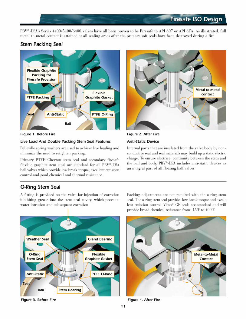
Firesafe ISO DesignFiresafe ISO Design
PBV®-USA’s Series 4400/5400/6400 valves have all been proven to be Firesafe to API 607 or API 6FA. As illustrated, fullmetal-to-metal contact is attained at all sealing areas after the primary soft seals have been destroyed during a fire.
Figure 1. Before Fire
Figure 3. Before Fire
Figure 2. After Fire
Metal-to-metalcontactFlexible
Graphite Gasket
Flexible GraphitePacking for
Firesafe Provision
PTFE Packing
PTFE O-Ring
Stem Packing Seal
O-Ring Stem Seal
Weather Seal
Stem Bearing
PTFE O-Ring
Gland Bearing
FlexibleGraphite Gasket
O-RingStem Seal
Anti-Static
Figure 4. After Fire
A fitting is provided on the valve for injection of corrosioninhibiting grease into the stem seal cavity, which preventswater intrusion and subsequent corrosion.
Metal-to-MetalContact
Anti-Static
Ball
Seat
Ball
Seat
11
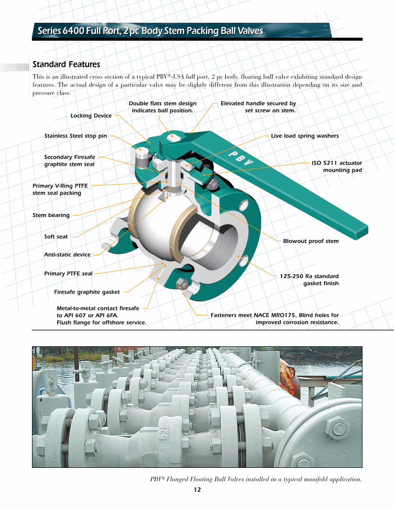
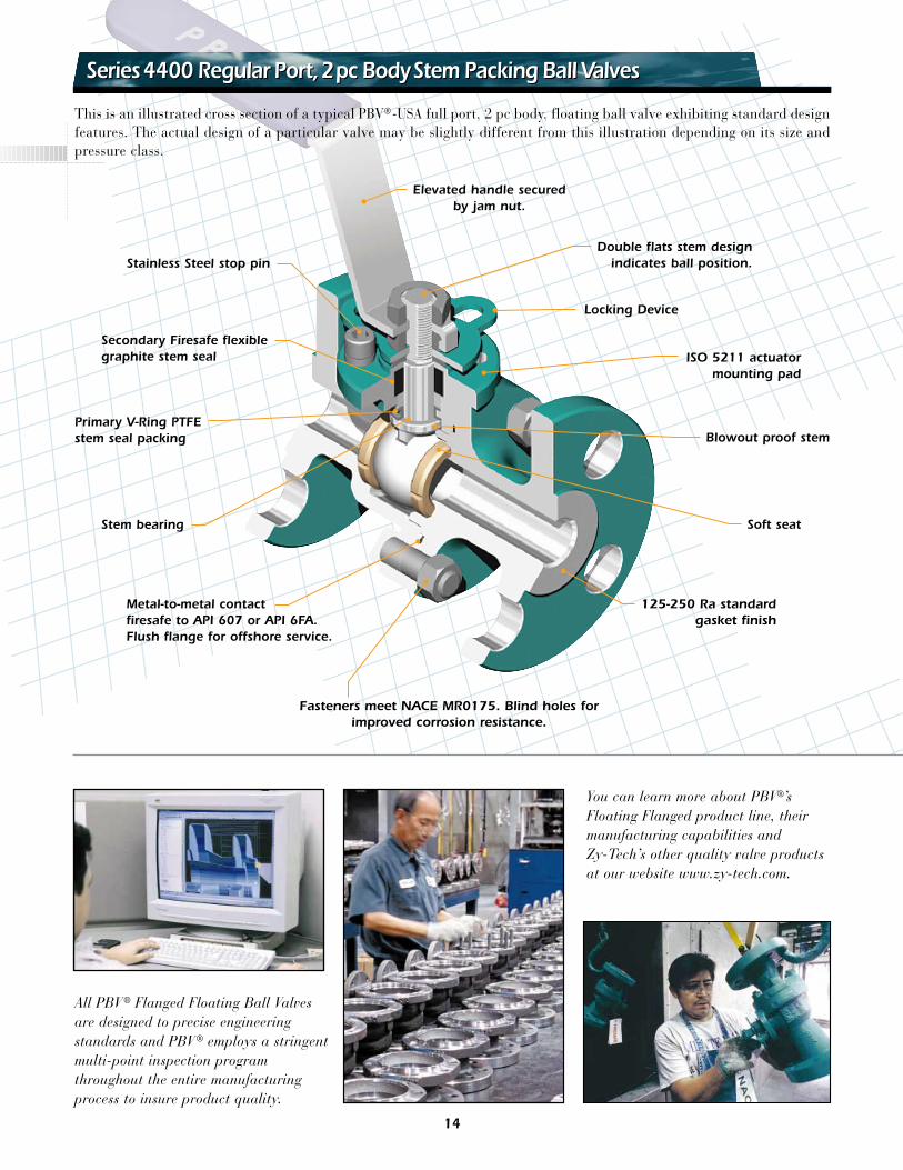
This is an illustrated cross section of a typical PBV®-USA full port, 2 pc body, floating ball valve exhibiting standard designfeatures. The actual design of a particular valve may be slightly different from this illustration depending on its size andpressure class.
Double flats stem designindicates ball position.
Elevated handle secured byset screw on stem.
Live load spring washers
ISO 5211 actuatormounting pad
Blowout proof stem
Stem bearing
125-250 Ra standardgasket finish
Stainless Steel stop pin
Secondary Firesafegraphite stem seal
Primary V-Ring PTFEstem seal packing
Anti-static device
Soft seat
Primary PTFE seal
Firesafe graphite gasket
Metal-to-metal contact firesafeto API 607 or API 6FA. Flush flange for offshore service.
Fasteners meet NACE MRO175. Blind holes forimproved corrosion resistance.
Locking Device
Standard Features
Series6400 Full Port,2pc Body Stem Packing Ball ValvesSeries6400 Full Port,2pc Body Stem Packing Ball Valves
PBV® Flanged Floating Ball Valves installed in a typical manifold application.
12
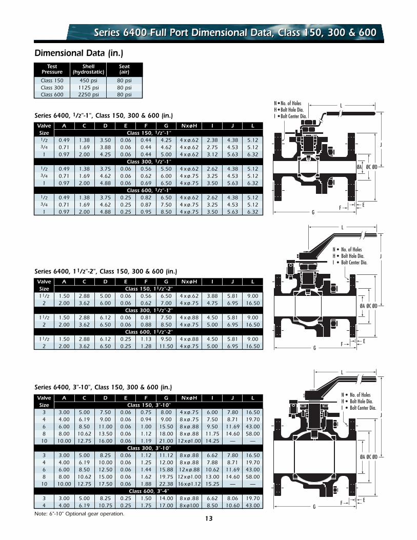
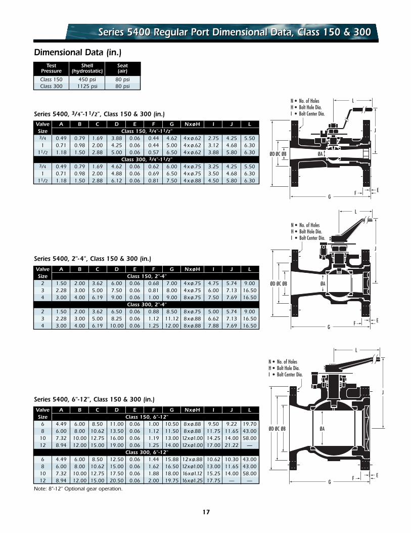
Series 6400 Full Port Dimensional Data, Class 150, 300 & 600Series 6400 Full Port Dimensional Data, Class 150, 300 & 600
Dimensional Data (in.)Test Shell Seat
Pressure (hydrostatic) (air)
Class 150 450 psi 80 psiClass 300 1125 psi 80 psiClass 600 2250 psi 80 psi
Valve A C D E F G NxøH I J LSize Class 150, 1/2"-1"1/2 0.49 1.38 3.50 0.06 0.44 4.25 4 x ø.62 2.38 4.38 5.123/4 0.71 1.69 3.88 0.06 0.44 4.62 4 x ø.62 2.75 4.53 5.121 0.97 2.00 4.25 0.06 0.44 5.00 4 x ø.62 3.12 5.63 6.32
Class 300, 1/2"-1"1/2 0.49 1.38 3.75 0.06 0.56 5.50 4 x ø.62 2.62 4.38 5.123/4 0.71 1.69 4.62 0.06 0.62 6.00 4 xø.75 3.25 4.53 5.121 0.97 2.00 4.88 0.06 0.69 6.50 4 xø.75 3.50 5.63 6.32
Class 600, 1/2"-1"1/2 0.49 1.38 3.75 0.25 0.82 6.50 4 x ø.62 2.62 4.38 5.123/4 0.71 1.69 4.62 0.25 0.87 7.50 4 xø.75 3.25 4.53 5.121 0.97 2.00 4.88 0.25 0.95 8.50 4 xø.75 3.50 5.63 6.32
Series 6400, 1/2"-1", Class 150, 300 & 600 (in.)
Valve A C D E F G NxøH I J LSize Class 150, 3"-10"
3 3.00 5.00 7.50 0.06 0.75 8.00 4 xø.75 6.00 7.80 16.504 4.00 6.19 9.00 0.06 0.94 9.00 8 xø.75 7.50 8.71 19.706 6.00 8.50 11.00 0.06 1.00 15.50 8 xø.88 9.50 11.69 43.008 8.00 10.62 13.50 0.06 1.12 18.00 8 xø.88 11.75 14.60 58.00
10 10.00 12.75 16.00 0.06 1.19 21.00 12xø1.00 14.25 — —Class 300, 3"-10"
3 3.00 5.00 8.25 0.06 1.12 11.12 8 xø.88 6.62 7.80 16.504 4.00 6.19 10.00 0.06 1.25 12.00 8 xø.88 7.88 8.71 19.706 6.00 8.50 12.50 0.06 1.44 15.88 12xø.88 10.62 11.69 43.008 8.00 10.62 15.00 0.06 1.62 19.75 12xø1.00 13.00 14.60 58.00
10 10.00 12.75 17.50 0.06 1.88 22.38 16xø1.12 15.25 — —Class 600, 3"-4"
3 3.00 5.00 8.25 0.25 1.50 14.00 8 xø.88 6.62 8.06 19.704 4.00 6.19 10.75 0.25 1.75 17.00 8xø1.00 8.50 10.60 43.00
Note: 6"-10" Optional gear operation.
Series 6400, 3"-10", Class 150, 300 & 600 (in.)
Valve A C D E F G NxøH I J LSize Class 150, 11/2"-2"11/2 1.50 2.88 5.00 0.06 0.56 6.50 4 x ø.62 3.88 5.81 9.00
2 2.00 3.62 6.00 0.06 0.62 7.00 4 xø.75 4.75 6.95 16.50Class 300, 11/2"-2"
11/2 1.50 2.88 6.12 0.06 0.81 7.50 4 x ø.88 4.50 5.81 9.002 2.00 3.62 6.50 0.06 0.88 8.50 4 xø.75 5.00 6.95 16.50
Class 600, 11/2"-2"11/2 1.50 2.88 6.12 0.25 1.13 9.50 4 x ø.88 4.50 5.81 9.00
2 2.00 3.62 6.50 0.25 1.28 11.50 4 xø.75 5.00 6.95 16.50
Series 6400, 11/2"-2", Class 150, 300 & 600 (in.)
EF
ØA ØC ØD
J
N • No. of HolesH • Bolt Hole Dia.I • Bolt Center Dia.
G
L
EF
ØA ØC ØD
JN • No. of HolesH • Bolt Hole Dia.I • Bolt Center Dia.
G
L
EF
ØA ØC ØD
J
N • No. of HolesH • Bolt Hole Dia.I • Bolt Center Dia.
G
L
13
Series4400 Regular Port,2pc BodyStem Packing Ball ValvesSeries4400 Regular Port,2pc BodyStem Packing Ball Valves
This is an illustrated cross section of a typical PBV®-USA full port, 2 pc body, floating ball valve exhibiting standard designfeatures. The actual design of a particular valve may be slightly different from this illustration depending on its size andpressure class.
Double flats stem designindicates ball position.
Locking Device
Elevated handle securedby jam nut.
ISO 5211 actuatormounting pad
Fasteners meet NACE MR0175. Blind holes forimproved corrosion resistance.
125-250 Ra standardgasket finish
Stainless Steel stop pin
Secondary Firesafe flexiblegraphite stem seal
Primary V-Ring PTFEstem seal packing Blowout proof stem
Soft seatStem bearing
Metal-to-metal contactfiresafe to API 607 or API 6FA.Flush flange for offshore service.
All PBV ® Flanged Floating Ball Valvesare designed to precise engineeringstandards and PBV ® employs a stringentmulti-point inspection programthroughout the entire manufacturingprocess to insure product quality.
You can learn more about PBV®’sFloating Flanged product line, theirmanufacturing capabilities andZy-Tech’s other quality valve productsat our website www.zy-tech.com.
14
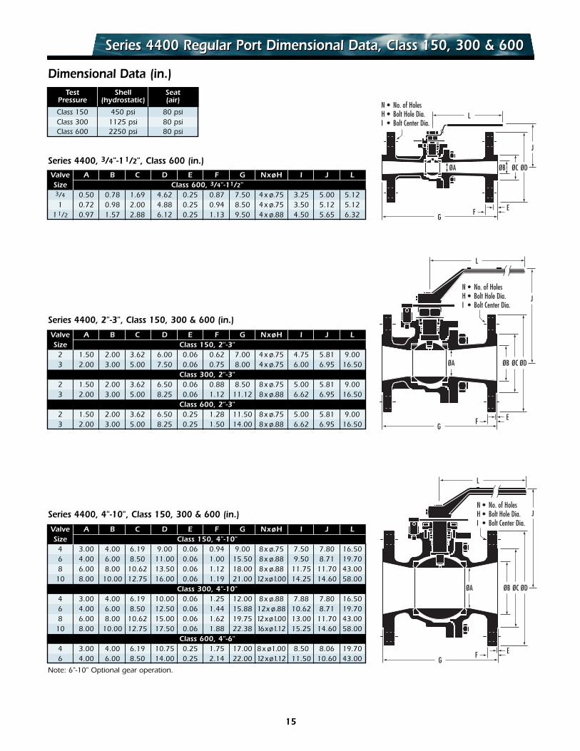
Series 4400 Regular Port Dimensional Data, Class 150, 300 & 600Series 4400 Regular Port Dimensional Data, Class 150, 300 & 600
Dimensional Data (in.)Test Shell Seat
Pressure (hydrostatic) (air)
Class 150 450 psi 80 psiClass 300 1125 psi 80 psiClass 600 2250 psi 80 psi
Valve A B C D E F G NxøH I J LSize Class 600, 3/4"-11/2"3/4 0.50 0.78 1.69 4.62 0.25 0.87 7.50 4x ø.75 3.25 5.00 5.121 0.72 0.98 2.00 4.88 0.25 0.94 8.50 4x ø.75 3.50 5.12 5.12
11/2 0.97 1.57 2.88 6.12 0.25 1.13 9.50 4x ø.88 4.50 5.65 6.32
Series 4400, 3/4"-11/2", Class 600 (in.)
Valve A B C D E F G NxøH I J LSize Class 150, 2"-3"
2 1.50 2.00 3.62 6.00 0.06 0.62 7.00 4x ø.75 4.75 5.81 9.003 2.00 3.00 5.00 7.50 0.06 0.75 8.00 4x ø.75 6.00 6.95 16.50
Class 300, 2"-3"2 1.50 2.00 3.62 6.50 0.06 0.88 8.50 8x ø.75 5.00 5.81 9.003 2.00 3.00 5.00 8.25 0.06 1.12 11.12 8x ø.88 6.62 6.95 16.50
Class 600, 2"-3"2 1.50 2.00 3.62 6.50 0.25 1.28 11.50 8x ø.75 5.00 5.81 9.003 2.00 3.00 5.00 8.25 0.25 1.50 14.00 8x ø.88 6.62 6.95 16.50
Series 4400, 2"-3", Class 150, 300 & 600 (in.)
Valve A B C D E F G NxøH I J LSize Class 150, 4"-10"
4 3.00 4.00 6.19 9.00 0.06 0.94 9.00 8x ø.75 7.50 7.80 16.506 4.00 6.00 8.50 11.00 0.06 1.00 15.50 8x ø.88 9.50 8.71 19.708 6.00 8.00 10.62 13.50 0.06 1.12 18.00 8x ø.88 11.75 11.70 43.00
10 8.00 10.00 12.75 16.00 0.06 1.19 21.00 12xø1.00 14.25 14.60 58.00Class 300, 4"-10"
4 3.00 4.00 6.19 10.00 0.06 1.25 12.00 8x ø.88 7.88 7.80 16.506 4.00 6.00 8.50 12.50 0.06 1.44 15.88 12x ø.88 10.62 8.71 19.708 6.00 8.00 10.62 15.00 0.06 1.62 19.75 12xø1.00 13.00 11.70 43.00
10 8.00 10.00 12.75 17.50 0.06 1.88 22.38 16xø1.12 15.25 14.60 58.00Class 600, 4"-6"
4 3.00 4.00 6.19 10.75 0.25 1.75 17.00 8x ø1.00 8.50 8.06 19.706 4.00 6.00 8.50 14.00 0.25 2.14 22.00 12xø1.12 11.50 10.60 43.00
Note: 6"-10" Optional gear operation.
Series 4400, 4"-10", Class 150, 300 & 600 (in.)
EF
ØB ØC ØD
J
N • No. of HolesH • Bolt Hole Dia.I • Bolt Center Dia.
ØA
G
L
EF
ØB ØC ØD
JN • No. of HolesH • Bolt Hole Dia.I • Bolt Center Dia.
ØA
G
L
EF
ØBØA ØC ØD
J
N • No. of HolesH • Bolt Hole Dia.I • Bolt Center Dia.
G
L
15
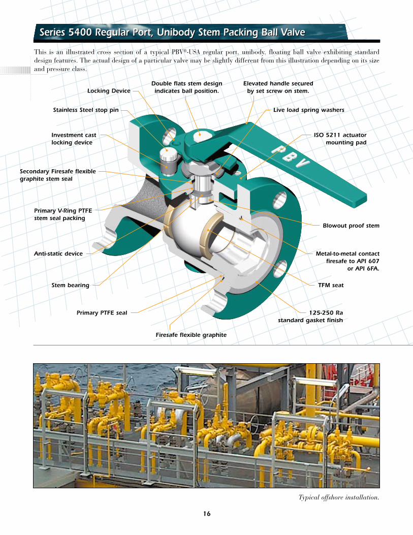
Series 5400 Regular Port, Unibody Stem Packing Ball ValveSeries 5400 Regular Port, Unibody Stem Packing Ball Valve
This is an illustrated cross section of a typical PBV®-USA regular port, unibody, floating ball valve exhibiting standarddesign features. The actual design of a particular valve may be slightly different from this illustration depending on its sizeand pressure class.
Double flats stem designindicates ball position.
Elevated handle securedby set screw on stem.
Live load spring washers
ISO 5211 actuatormounting pad
125-250 Rastandard gasket finish
Stainless Steel stop pin
Locking Device
Secondary Firesafe flexiblegraphite stem seal
Investment castlocking device
Primary V-Ring PTFEstem seal packing
Anti-static device
Stem bearing TFM seat
Primary PTFE seal
Firesafe flexible graphite
Metal-to-metal contactfiresafe to API 607
or API 6FA.
Blowout proof stem
Typical offshore installation.
16
Series 5400 Regular Port Dimensional Data, Class 150 & 300Series 5400 Regular Port Dimensional Data, Class 150 & 300
Dimensional Data (in.)Test Shell Seat
Pressure (hydrostatic) (air)
Class 150 450 psi 80 psiClass 300 1125 psi 80 psi
Valve A B C D E F G NxøH I J LSize Class 150, 3/4"-11/2"3/4 0.49 0.79 1.69 3.88 0.06 0.44 4.62 4x ø.62 2.75 4.25 5.501 0.71 0.98 2.00 4.25 0.06 0.44 5.00 4x ø.62 3.12 4.68 6.30
11/2 1.18 1.50 2.88 5.00 0.06 0.57 6.50 4x ø.62 3.88 5.80 6.30Class 300, 3/4"-11/2"
3/4 0.49 0.79 1.69 4.62 0.06 0.62 6.00 4x ø.75 3.25 4.25 5.501 0.71 0.98 2.00 4.88 0.06 0.69 6.50 4x ø.75 3.50 4.68 6.30
11/2 1.18 1.50 2.88 6.12 0.06 0.81 7.50 4x ø.88 4.50 5.80 6.30
Series 5400, 3/4"-11/2", Class 150 & 300 (in.)
Valve A B C D E F G NxøH I J LSize Class 150, 6"-12"
6 4.49 6.00 8.50 11.00 0.06 1.00 10.50 8xø.88 9.50 9.22 19.708 6.00 8.00 10.62 13.50 0.06 1.12 11.50 8xø.88 11.75 11.65 43.00
10 7.32 10.00 12.75 16.00 0.06 1.19 13.00 12xø1.00 14.25 14.00 58.0012 8.94 12.00 15.00 19.00 0.06 1.25 14.00 12xø1.00 17.00 21.22 —
Class 300, 6"-12"6 4.49 6.00 8.50 12.50 0.06 1.44 15.88 12xø.88 10.62 10.30 43.008 6.00 8.00 10.62 15.00 0.06 1.62 16.50 12xø1.00 13.00 11.65 43.00
10 7.32 10.00 12.75 17.50 0.06 1.88 18.00 16xø1.12 15.25 14.00 58.0012 8.94 12.00 15.00 20.50 0.06 2.00 19.75 16xø1.25 17.75 — —
Note: 8"-12" Optional gear operation.
Series 5400, 6"-12", Class 150 & 300 (in.)
Valve A B C D E F G NxøH I J LSize Class 150, 2"-4"
2 1.50 2.00 3.62 6.00 0.06 0.68 7.00 4xø.75 4.75 5.74 9.003 2.28 3.00 5.00 7.50 0.06 0.81 8.00 4xø.75 6.00 7.13 16.504 3.00 4.00 6.19 9.00 0.06 1.00 9.00 8xø.75 7.50 7.69 16.50
Class 300, 2"-4"2 1.50 2.00 3.62 6.50 0.06 0.88 8.50 8xø.75 5.00 5.74 9.003 2.28 3.00 5.00 8.25 0.06 1.12 11.12 8xø.88 6.62 7.13 16.504 3.00 4.00 6.19 10.00 0.06 1.25 12.00 8xø.88 7.88 7.69 16.50
Series 5400, 2"-4", Class 150 & 300 (in.)
EF
ØB ØAØCØD
J
N • No. of HolesH • Bolt Hole Dia.I • Bolt Center Dia.
G
L
EF
ØB ØAØCØD
J
N • No. of HolesH • Bolt Hole Dia.I • Bolt Center Dia.
G
L
EF
ØB ØAØCØD
J
N • No. of HolesH • Bolt Hole Dia.I • Bolt Center Dia.
G
L
17
Series4500 Regular & 6500 Full Port,2pc O-Ring Stem Ball Valves•API 6DSeries4500 Regular & 6500 Full Port,2pc O-Ring Stem Ball Valves•API 6D
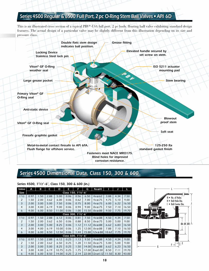
This is an illustrated cross section of a typical PBV®-USA full port, 2 pc body, floating ball valve exhibiting standard designfeatures. The actual design of a particular valve may be slightly different from this illustration depending on its size andpressure class.
Double flats stem designindicates ball position.
Elevated handle secured byset screw on stem.
ISO 5211 actuatormounting pad
Blowout proof stem
125-250 Rastandard gasket finish
Locking DeviceStainless Steel lock pin
Grease fitting
Viton® GF O-Ringweather seal
Primary Viton® GFO-Ring seal
Large grease pocket
Anti-static device
Soft seatFiresafe graphite gasket
Metal-to-metal contact firesafe to API 6FA.Flush flange for offshore service.
Fasteners meet NACE MRO175.Blind holes for improved
corrosion resistance.
Viton® GF O-Ring seal
Valve A B C D E F G NxøH I J LSize Class 150, 11/2"-6"11/2 0.97 1.50 2.88 5.00 0.06 0.56 6.50 4x ø.62 3.88 4.34 7.50
2 1.50 2.00 3.62 6.00 0.06 0.62 7.00 4x ø.75 4.75 5.10 9.003 2.00 3.00 5.00 7.50 0.06 0.75 8.00 4x ø.75 6.00 6.22 16.504 3.00 4.00 6.19 9.00 0.06 0.94 9.00 8x ø.75 7.50 7.10 16.506 4.00 6.00 8.50 11.00 0.06 1.00 15.50 8x ø.88 9.50 7.75 19.70
Class 300, 11/2"-6"11/2 0.97 1.50 2.88 6.12 0.06 0.81 7.50 4x ø.88 4.50 4.34 7.50
2 1.50 2.00 3.62 6.50 0.06 0.88 8.50 8x ø.75 5.00 5.00 9.003 2.00 3.00 5.00 8.25 0.06 1.12 11.12 8x ø.88 6.62 6.83 16.504 3.00 4.00 6.19 10.00 0.06 1.25 12.00 8x ø.88 7.88 7.10 16.506 4.00 6.00 8.50 12.50 0.06 1.44 15.88 12x ø.88 10.62 7.75 19.70
Class 600, 11/2"-6"11/2 0.97 1.50 2.88 6.12 0.25 1.13 9.50 4x ø.88 4.50 4.34 9.00
2 1.50 2.00 3.62 6.50 0.25 1.28 11.50 8x ø.75 5.00 5.00 9.003 2.00 3.00 5.00 8.25 0.25 1.50 14.00 8x ø.88 6.62 6.23 16.504 3.00 4.00 6.19 10.75 0.25 1.75 17.00 8xø1.00 8.50 7.11 19.706 4.00 6.00 8.50 14.00 0.25 2.14 22.00 12x ø1.12 11.50 8.30 43.00
Series 4500, 11/2"- 6", Class 150, 300 & 600 (in.)
Stem bearing
EF
ØA ØC ØD
J
N • No. of HolesH • Bolt Hole Dia.I • Bolt Center Dia.
G
L
Series4500 Dimensional Data, Class 150, 300 & 600Series4500 Dimensional Data, Class 150, 300 & 600
18
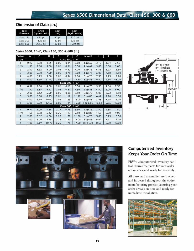
Series 6500 Dimensional Data, Class 150, 300 & 600Series 6500 Dimensional Data, Class 150, 300 & 600
Dimensional Data (in.)
Series 6500, 1"- 6", Class 150, 300 & 600 (in.)
EF
ØA ØC ØD
JN • No. of HolesH • Bolt Hole Dia.I • Bolt Center Dia.
G
LValve A C D E F G NxøH I J LSize Class 150, 1"-6"
1 0.97 2.00 4.25 0.06 0.44 5.00 4 x ø.62 3.12 4.34 7.5011/2 1.50 2.88 5.00 0.06 0.56 6.50 4 x ø.62 3.88 5.00 9.00
2 2.00 3.62 6.00 0.06 0.62 7.00 4 x ø.75 4.75 6.23 16.503 3.00 5.00 7.50 0.06 0.75 8.00 4 x ø.75 6.00 7.10 16.504 4.00 6.19 9.00 0.06 0.94 9.00 8x ø.75 7.50 7.75 19.706 6.00 8.50 11.00 0.06 1.00 15.50 8x ø.88 9.50 9.56 43.00
Class 300, 1"-6"1 0.97 2.00 4.88 0.06 0.69 6.50 4 x ø.75 3.50 4.34 7.50
11/2 1.50 2.88 6.12 0.06 0.81 7.50 4 x ø.88 4.50 5.00 9.002 2.00 3.62 6.50 0.06 0.88 8.50 8x ø.75 5.00 6.23 16.503 3.00 5.00 8.25 0.06 1.12 11.12 8x ø.88 6.62 7.10 16.504 4.00 6.19 10.00 0.06 1.25 12.00 8x ø.88 7.88 7.75 19.706 6.00 8.50 12.50 0.06 1.44 15.88 12x ø.88 10.62 9.56 43.00
Class 600, 1"-4"1 0.97 2.00 4.88 0.25 0.95 8.50 4 x ø.75 3.50 4.34 7.50
11/2 1.50 2.88 6.12 0.25 1.13 9.50 4 x ø.88 4.50 5.00 9.002 2.00 3.62 6.50 0.25 1.28 11.50 8x ø.75 5.00 6.23 16.503 3.00 5.00 8.25 0.25 1.50 14.00 8x ø.88 6.62 7.11 19.704 4.00 6.19 10.75 0.25 1.75 17.00 8x ø1.00 8.50 8.30 43.00
19
PBV®'s computerized inventory con-trol insures the parts for your orderare in stock and ready for assembly.
All parts and assemblies are trackedand inspected throughout the entiremanufacturing process, assuring yourorder arrives on time and ready forimmediate installation.
Computerized InventoryKeeps Your Order On Time
Test Shell Seat SeatPressure (hydrostatic) (air) (hydrostatic)
Class 150 450 psi 80 psi 320 psiClass 300 1125 psi 80 psi 825 psiClass 600 2250 psi 80 psi 1650 psi
15
13
5 11
16 46
1
7 224
20
24
8
19
33 353
14
62
12
2318
25
21
15
14
16
17
1
47
11
13
24
29
8
20
19
33 34 35
3
5
618
122
20
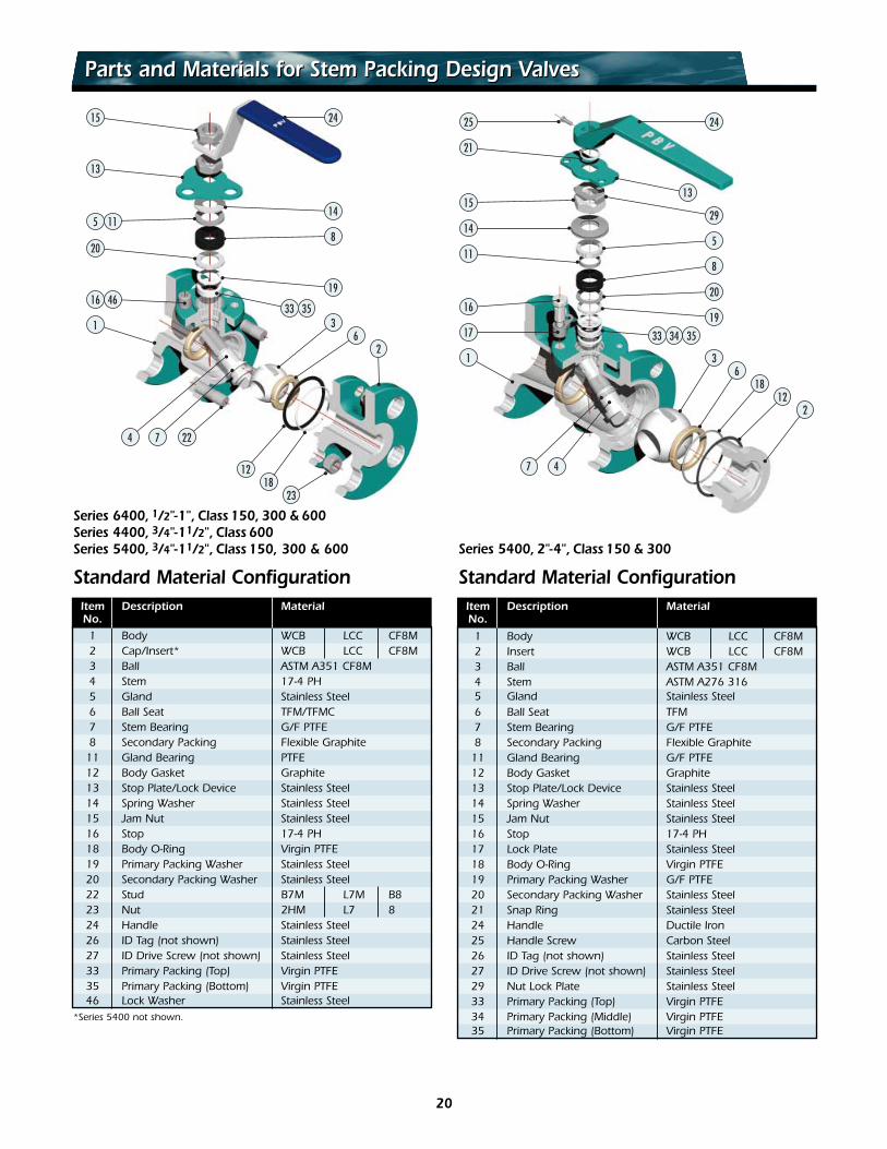
Standard Material Configuration Standard Material ConfigurationItem Description MaterialNo.1 Body WCB LCC CF8M2 Cap/Insert* WCB LCC CF8M3 Ball ASTM A351 CF8M4 Stem 17-4 PH5 Gland Stainless Steel6 Ball Seat TFM/TFMC7 Stem Bearing G/F PTFE8 Secondary Packing Flexible Graphite
11 Gland Bearing PTFE12 Body Gasket Graphite13 Stop Plate/Lock Device Stainless Steel14 Spring Washer Stainless Steel15 Jam Nut Stainless Steel16 Stop 17-4 PH18 Body O-Ring Virgin PTFE19 Primary Packing Washer Stainless Steel20 Secondary Packing Washer Stainless Steel22 Stud B7M L7M B823 Nut 2HM L7 824 Handle Stainless Steel26 ID Tag (not shown) Stainless Steel27 ID Drive Screw (not shown) Stainless Steel33 Primary Packing (Top) Virgin PTFE35 Primary Packing (Bottom) Virgin PTFE46 Lock Washer Stainless Steel
*Series 5400 not shown.
Item Description MaterialNo.
1 Body WCB LCC CF8M2 Insert WCB LCC CF8M3 Ball ASTM A351 CF8M4 Stem ASTM A276 3165 Gland Stainless Steel6 Ball Seat TFM7 Stem Bearing G/F PTFE8 Secondary Packing Flexible Graphite
11 Gland Bearing G/F PTFE12 Body Gasket Graphite13 Stop Plate/Lock Device Stainless Steel14 Spring Washer Stainless Steel15 Jam Nut Stainless Steel16 Stop 17-4 PH17 Lock Plate Stainless Steel18 Body O-Ring Virgin PTFE19 Primary Packing Washer G/F PTFE20 Secondary Packing Washer Stainless Steel21 Snap Ring Stainless Steel24 Handle Ductile Iron25 Handle Screw Carbon Steel26 ID Tag (not shown) Stainless Steel27 ID Drive Screw (not shown) Stainless Steel29 Nut Lock Plate Stainless Steel33 Primary Packing (Top) Virgin PTFE34 Primary Packing (Middle) Virgin PTFE35 Primary Packing (Bottom) Virgin PTFE
Series 6400, 1/2"-1", Class 150, 300 & 600Series 4400, 3/4"-11/2", Class 600Series 5400, 3/4"-11/2", Class 150, 300 & 600 Series 5400, 2"-4", Class 150 & 300
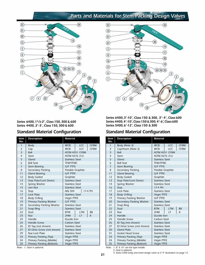
Parts and Materials for Stem Packing Design ValvesParts and Materials for Stem Packing Design Valves
25
21
15
29
5
17
1
4 227
16
8
13
24
11
20
19
33 34 353
14
623
2
1812
25
13
31
21
5
8
17
6
4 227
16
30
24
11
20
19
33 34 35
14
32
23
1218
1
21
Parts and Materials for Stem Packing Design ValvesParts and Materials for Stem Packing Design Valves
Series 6400,11/2-2", Class 150,300 & 600Series 4400, 2"-3", Class 150,300 & 600
Item Description MaterialNo.
1 Body WCB LCC CF8M2 Cap WCB LCC CF8M3 Ball ASTM A351 CF8M4 Stem ASTM A276 3165 Gland Stainless Steel6 Ball Seat TFM/TFMC7 Stem Bearing G/F PTFE8 Secondary Packing Flexible Graphite
11 Gland Bearing G/F PTFE12 Body Gasket Graphite13 Stop Plate/Lock Device Stainless Steel14 Spring Washer Stainless Steel15 Jam Nut Stainless Steel16 Stop AISI 304 17-4 PH17 Lock Plate Stainless Steel18 Body O-Ring Virgin PTFE19 Primary Packing Washer G/F PTFE20 Secondary Packing Washer Stainless Steel21 Snap Ring Stainless Steel22 Stud B7M L7M B823 Nut 2HM L7 824 Handle Ductile Iron25 Handle Screw Carbon Steel26 ID Tag (not shown) Stainless Steel27 ID Drive Screw (not shown) Stainless Steel29 Nut Lock Plate Stainless Steel33 Primary Packing (Top) Virgin PTFE34 Primary Packing (Middle) Virgin PTFE35 Primary Packing (Bottom) Virgin PTFE
Note: 1. Gear is optional.
Item Description MaterialNo.
1 Body (Note 3) WCB LCC CF8M2 Cap/Insert (Note 3) WCB LCC CF8M3 Ball ASTM A351 CF8M4 Stem ASTM A276 3165 Gland Stainless Steel6 Ball Seat TFM/TFMC7 Stem Bearing G/F PTFE8 Secondary Packing Flexible Graphite
11 Gland Bearing G/F PTFE12 Body Gasket Graphite13 Stop Plate/Lock Device Stainless Steel14 Spring Washer Stainless Steel16 Stop 17-4 PH17 Lock Plate Stainless Steel18 Body O-Ring Virgin PTFE19 Primary Packing Washer G/F PTFE20 Secondary Packing Washer Stainless Steel21 Snap Ring Stainless Steel22 Stud B7M L7M B823 Nut 2HM L7 824 Handle Ductile Iron25 Handle Screw Carbon Steel26 ID Tag (not shown) Stainless Steel27 ID Drive Screw (not shown) Stainless Steel30 Gland Plate Stainless Steel31 Socket Head Screw Stainless Steel33 Primary Packing (Top) Virgin PTFE34 Primary Packing (Middle) Virgin PTFE35 Primary Packing (Bottom) Virgin PTFE
Note: 1. 8" & 10" use bar type handle.2. Gear is optional.3. Series 5400 body and insert design same as 2"-4" illustration on page 15.
Standard Material ConfigurationStandard Material Configuration
Series 6400,3"-10", Class 150 & 300, 3"- 4", Class 600Series 4400,4"-10",Class150 &300,4"-6",Class600Series 5400,6"-12", Class 150 & 300
25
21
11
13
5
35
6
4 227
32
17
24
15
34
3
223
1812
1
21
17
1
16
2234 32
13
24
35
7
26
3
18
4
12
23
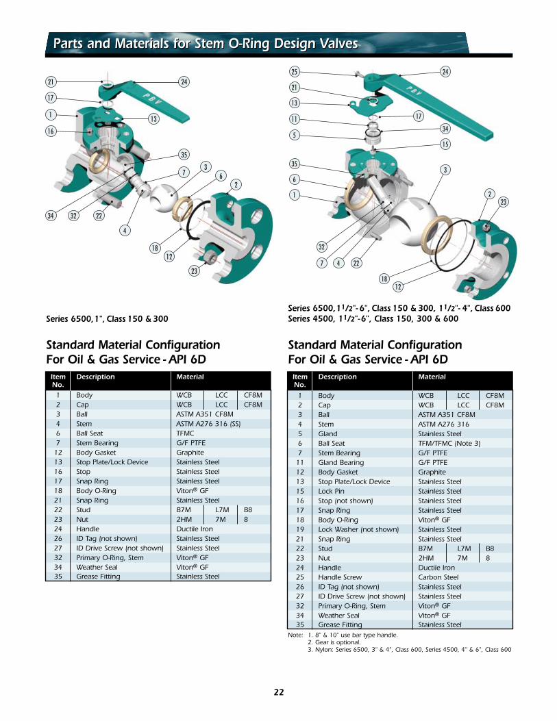
Parts and Materials for Stem O-Ring Design ValvesParts and Materials for Stem O-Ring Design Valves
Series 6500,1", Class 150 & 300Series 6500,11/2"- 6", Class 150 & 300, 11/2"- 4", Class 600Series 4500, 11/2"-6", Class 150, 300 & 600
Item Description MaterialNo.
1 Body WCB LCC CF8M2 Cap WCB LCC CF8M3 Ball ASTM A351 CF8M4 Stem ASTM A276 3165 Gland Stainless Steel6 Ball Seat TFM/TFMC (Note 3)7 Stem Bearing G/F PTFE
11 Gland Bearing G/F PTFE12 Body Gasket Graphite13 Stop Plate/Lock Device Stainless Steel15 Lock Pin Stainless Steel16 Stop (not shown) Stainless Steel17 Snap Ring Stainless Steel18 Body O-Ring Viton® GF19 Lock Washer (not shown) Stainless Steel21 Snap Ring Stainless Steel22 Stud B7M L7M B823 Nut 2HM 7M 824 Handle Ductile Iron25 Handle Screw Carbon Steel26 ID Tag (not shown) Stainless Steel27 ID Drive Screw (not shown) Stainless Steel32 Primary O-Ring, Stem Viton® GF34 Weather Seal Viton® GF35 Grease Fitting Stainless Steel
Note: 1. 8" & 10" use bar type handle.2. Gear is optional.3. Nylon: Series 6500, 3" & 4", Class 600, Series 4500, 4" & 6", Class 600
Item Description MaterialNo.1 Body WCB LCC CF8M2 Cap WCB LCC CF8M3 Ball ASTM A351 CF8M4 Stem ASTM A276 316 (SS)6 Ball Seat TFMC7 Stem Bearing G/F PTFE
12 Body Gasket Graphite13 Stop Plate/Lock Device Stainless Steel16 Stop Stainless Steel17 Snap Ring Stainless Steel18 Body O-Ring Viton® GF21 Snap Ring Stainless Steel22 Stud B7M L7M B823 Nut 2HM 7M 824 Handle Ductile Iron26 ID Tag (not shown) Stainless Steel27 ID Drive Screw (not shown) Stainless Steel32 Primary O-Ring, Stem Viton® GF34 Weather Seal Viton® GF35 Grease Fitting Stainless Steel
Standard Material ConfigurationFor Oil & Gas Service - API 6D
Standard Material ConfigurationFor Oil & Gas Service - API 6D
22
33 34 35
6 7
18 12
11
8
19
76 32 18 12
34
11
23
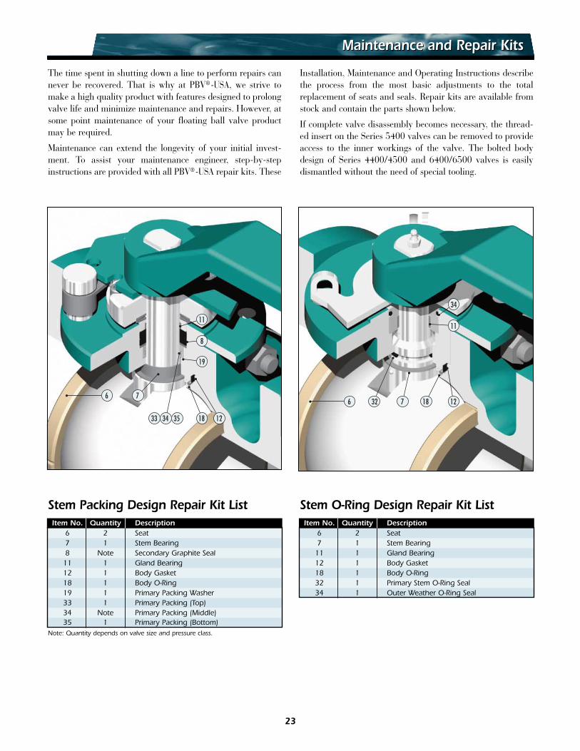
Maintenance and Repair KitsMaintenance and Repair Kits
Item No. Quantity Description6 2 Seat7 1 Stem Bearing8 Note Secondary Graphite Seal
11 1 Gland Bearing12 1 Body Gasket18 1 Body O-Ring19 1 Primary Packing Washer33 1 Primary Packing (Top)34 Note Primary Packing (Middle)35 1 Primary Packing (Bottom)
Note: Quantity depends on valve size and pressure class.
Stem Packing Design Repair Kit ListItem No. Quantity Description
6 2 Seat7 1 Stem Bearing
11 1 Gland Bearing12 1 Body Gasket18 1 Body O-Ring32 1 Primary Stem O-Ring Seal34 1 Outer Weather O-Ring Seal
Stem O-Ring Design Repair Kit List
The time spent in shutting down a line to perform repairs cannever be recovered. That is why at PBV®-USA, we strive tomake a high quality product with features designed to prolongvalve life and minimize maintenance and repairs. However, atsome point maintenance of your floating ball valve productmay be required.
Maintenance can extend the longevity of your initial invest-ment. To assist your maintenance engineer, step-by-stepinstructions are provided with all PBV®-USA repair kits. These
Installation, Maintenance and Operating Instructions describethe process from the most basic adjustments to the totalreplacement of seats and seals. Repair kits are available fromstock and contain the parts shown below.
If complete valve disassembly becomes necessary, the thread-ed insert on the Series 5400 valves can be removed to provideaccess to the inner workings of the valve. The bolted bodydesign of Series 4400/4500 and 6400/6500 valves is easilydismantled without the need of special tooling.
©2006 Zy-Tech Global Industries, Inc. • PBV®-USA, Inc. is a wholly-owned subsidiary of Zy-tech Global Industries, Inc. • PBV® is a registered trademark ofZy-Tech Global Industries, Inc. • Viton® is a registered Trademark of Dupont Dow Elastomers. • HASTELLOY® is a registered trademark of Haynes International, Inc.PEEK™ is a trademark of Victrex Plc. • Monel® is a registered trademark of Special Metals Corporation, USA • PBV_FLTFLGBV_REV506 • Litho USA
Zy-Tech General Terms and Conditions of Sale: By acceptance of the goods described herein, the Purchaser expressly acknowledges and agrees as follows:
1. Warranty: The warranty described below applies only to new or unused goods or goods reconditioned by Zy-Tech Global Industries, Inc. (Seller). The Seller specifically disclaims any warranty for used goods or goods sold as is.For a period of one (1) year after date of purchase of any of the goods described herein, Seller warrants such goods shall remain free from failure due to defects in workmanship and materials incorporated therein by or forSeller provided such failure shall not have been caused or contributed to by improper usage, service or application, improper installation or maintenance, repairs, alterations, or modifications effected by or for the user, misuse,negligence or accident. In the event of failure for which Seller has assumed warranty obligations hereunder, and provided written notification of such failure shall be immediately given to Seller, it agrees to repair, or at its option,to replace the goods sold at its sold expense. Apart from the warranty and undertaking above set forth, or unless otherwise specifically consented to in writing by Seller, Seller assumes no obligation or liability for losses, expenseor damages, direct or consequential, suffered or incurred as a result of any failure of, or defect in, the goods described herein, including but not limited to, such costs, expenses or damages as may result of any failure of, ordefect in, the goods described herein, including but not limited to, such costs, expenses or damages as may result from the necessity to remove, replace, restore or transport the goods from any location or service in which theymay be used, regardless of the cause of such failure or defect. This warranty extends only to the original Purchaser of the goods and is the only warranty made by Seller in connection therewith. There are no other warranties,express or implied, of any kind given with respect to the goods, their merchantability, fitness for any particular purpose or usage, or otherwise, nor is any person authorized to extend on behalf of Seller any form of warrantyother than that above set forth. The goods described herein are not sold or distributed by Seller for personal, family or household purposes, nor are they normally suited for use as such.2. Prices: Prices and other terms of sale where set forth in current price sheets are subject to change without notice. Stenographic or clerical errors are subject to correction.3. Acceptance of Orders and Special Orders: All orders are subject to acceptance by Seller at its home office, Stafford, Texas, only. No assignment of the Purchaser’s rights may be made without the written consent of the Seller.Orders for special materials are subject to cancellation only upon agreement to make payment for the work performed, material used, and a reasonable profit.4. Terms, Payment and Partial Shipment: All accounts are payable net 30 days of invoice date. One percent (1%) per month interest charged on accounts after 30 days, or twelve percent (12%) annually. All accounts arepayable in United States dollars, free of exchange, collection, or any other charges. If in the sole discretion of Seller, the financial condition of the Purchaser at any time so requires, Seller retains the right to require full orpartial payment in advance, to set spending limits for credit accounts or to require other adequate assurances of financial responsibility. Seller reserves the right to make partial shipments from time to time and render invoic-es therefore, which shall be due and payable as provided in said invoices.5. Freight Charges: Unless otherwise specifically noted, standard shipping charges (calculated by product weight, not including packaging) shall be added or be in addition to the price quoted and Purchaser agrees to pay thesame to Seller.6. Taxes: Unless otherwise specifically noted, the amount of any sales, use, occupancy, excise tax, or other tax, of any nature, federal, state, or local, for which Seller is legally liable, either initially or through failure of pay-ment by Purchaser, shall be added or be in addition to the price quoted and Purchaser agrees to pay the same to Seller.7. Unavoidable Conditions: Seller shall not be liable for failure to deliver or delays in delivery occasioned by causes beyond its control, including, without limitation, strikes, lockouts, fires, embargoes, war or other outbreaksof hostilities, acts of God, inability to obtain shipping space, machinery, breakdowns, delays of carriers or suppliers, and governmental acts or regulations.8. Returns and Cancellations: No product may be returned without Seller’s prior written consent. All goods returned are subject to a handling charge plus freight in both directions, restocking fees and charges for any requiredreconditioning, unless otherwise specified in writing by Seller. Overages, shortages and incorrect material claims must be made in writing within ten (10) days of receipt of goods. Cancellation of orders once placed with andaccepted by Seller may be made only with its written consent.9. No Waiver: Seller’s failure to insist upon any of the terms, covenants, or conditions listed herein or to exercise any right hereunder shall not be construed as a waiver or relinquishment of the future performances of anysuch term, covenant or condition, or the future exercise of such right or a waiver or relinquishment or waiver of any other term, covenant or condition or the exercise of any other rights hereunder.10. Drawings, Data and Confidential Information: The weights, dimensions, capacities, prices, performance ratings and other data included in catalogues, prospectuses, circulars, advertisements, illustrated matter and pricelists constitute a guide. These data shall not be binding except to the extent that they are by reference expressly included in the purchase order. Any drawings or technical documents intended for use in the manufacture ofmachinery, equipment, plants, parts, or other material and any ancillary services associated therewith (Material), or a part thereof, and submitted to the Purchaser prior or subsequent to the formation of the purchase order,remain the exclusive property of the Seller. They shall not, without the Seller’s consent, be utilized by the Purchaser or copied, reproduced, transmitted or communicated to an unauthorized third party, provided, however, thatthe said plans and documents shall be the property of the Purchaser if it is expressly so agreed in writing. Any drawings or technical documents intended for use in the construction of the Material or of part thereof and sub-mitted to the Seller by the Purchaser prior or subsequent to the formation of the purchase order remain the exclusive property of the Purchaser. They shall not, without Purchaser's consent in writing, be utilized by the Selleror copied, reproduced, transmitted or communicated to an unauthorized third party.11. Governing Law: This contract shall be governed by, construed and enforced in accordance with the laws of the State of Texas.12. Totality of Agreement, Special Provisions, Modifications: This instrument constitutes the entire agreement of the parties with respect to all matters and things herein mentioned. Purchaser warrants, represents and agreesthat it has inspected the goods and otherwise made inquiry and review, upon its own behalf, concerning the nature, characteristics and quality of the materials and workmanship incorporated therein at or prior to delivery,that it is fully contented and satisfied therewith and has independently determined that the goods are in all respects fit and usable for all purposes for which they are intended to be employed by Purchaser. It is expresslyacknowledged and agreed by and between the parties that neither party has, nor is now, relying upon any collateral, prior or contemporaneous agreement, written or oral, assurance or assurances, representation or war-ranty, of any kind or nature as to or respecting the condition or capabilities of the goods and the other matters and things, rights and responsibilities herein fixed and described. No modification, waiver or discharge of anyterm or provision of this instrument shall be implied by law, nor shall any alteration, modification or acquittance of any such term or provision be effective for any purpose unless in writing signed by or upon behalf of theparty charged therewith.(1) Returns are accepted within 180 days of shipment. Restocking charges for returned standard materials is 15%. Cancellation of orders for standard materials prior to shipment may incur a 10% minimum cancellation charge.Cancellation of non-standard material may incur up to 100% cancellation charge depending on stage of work in progress. All material returned to Zy-Tech Global Industries must be accompanied by a prior written ReturnedGoods Authorization (RGA) form and freight must be prepaid. All material is subject to inspection and final disposition by Zy-Tech Global Industries quality department. A clean up and or re-certification charge may apply toany returned materials. Special items, buyouts, and modified products are non-returnable. (2) All products are subject to prior sales. (3) All sales are subject to Zy-Tech Global Industries standard Terms & Conditions.13. Export Regulations: Zy-Tech products can only be exported in accordance with U.S. Export Administration Regulations and other U.S. legal requirements. Diversion contrary to U.S. law is prohibited.
Represented By:
10600 Corporate Drive, Stafford, Texas 77477(281) 565-1010 • (800) 231-3530 • Fax (281) 565-3171
Licensed for manufacture inaccordance with API 6D-0129and fire tested to API 6FA or 607