pc-based edm system operation manual - anotronic · pc-based edm system operation manual unit 3,...
TRANSCRIPT

PC-Based EDM System
Operation Manual
UNIT 3, HOLLINGDON DEPOT, STEWKLEY ROAD, SOULBURY,NR. LEIGHTON BUZZARD, BEDS., LU7 0DF.
Tel. +44 01525 270261 Fax. +44 01525 270235Email [email protected]
Internet http://www.anotronic.com

Issue - JUNE-05-UK I - 1
I PC-Based EDM System Installation Information

Issue - JUNE-05-UK I - 2
1. Diagram

Issue - JUNE-05-UK I - 3
2. Warning Sign Interpretation :
DANGER Fire potential hazard keep flames away
DANGER Do not touch the electrode during operation
WARNING The minimum depth of the electrical discharge below the fluid surface shall be 50mm
WARNING Health potential hazard Fumes must be removed by extraction equipment
DANGER Hazardous voltage Turn off power before servicing

Issue - JUNE-05-UK I - 4
WARNING Fire potential hazard The flashpoint of dielectric fluid must be over 70°C
Only to be opened by a technician to avoid any danger
Lubricant

Issue - JUNE-05-UK I - 5
3. Warning Sign Position:
C E
LOGO

Issue - JUNE-05-UK I - 6
Back
Front
C E
LOGO
Issue - JUNE-05-UK I - 7
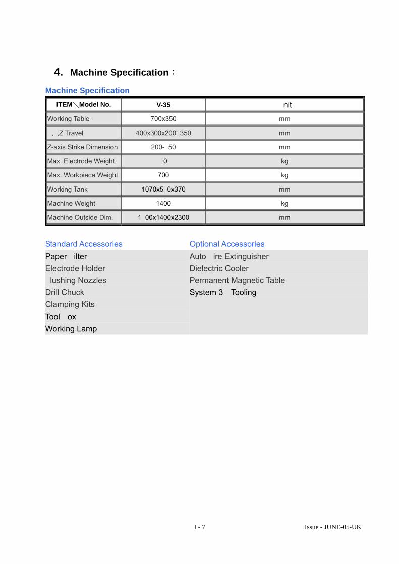
4. Machine Specification:
Machine Specification
ITEM\Model No. V-35 Unit
Working Table 700x350 mm
X,Y,Z Travel 400x300x200+350 mm
Z-axis Strike Dimension 200-650 mm
Max. Electrode Weight 90 kg
Max. Workpiece Weight 700 kg
Working Tank 1070x580x370 mm
Machine Weight 1400 kg
Machine Outside Dim. 1600x1400x2300 mm
Standard Accessories Optional Accessories Paper Filter Electrode Holder Flushing Nozzles Drill Chuck Clamping Kits Tool Box Working Lamp
Auto Fire Extinguisher Dielectric Cooler Permanent Magnetic Table System 3R Tooling

Issue - JUNE-05-UK I - 8
5. Packing, Transportation, Wooden case Disassembling & Lifting:
5.1 The E.D.M. machine is packed in a standard export wooden case, it must be handled carefully without dropping or tipping the machine. Care must be taken during transportation.
5.2 Detailed Checks on the unloaded Wooden Case: Please first check the outside of the wooden case as soon as you receive it. If you find any damage or have any queries, notify us or our agents immediately before you unpack the wooden case. *Please do not place the packed machine outdoors without suitable protection to
prevent accidental damage or the absorption of moisture 5.3 Wooden Case Disassembling Procedures(Shown as Pic. 1)
Please read the following procedure and see the figure shown below:
(1)Remove the upper cover first。
(2)Remove the side covers of front & rear machine part。
(3)Remove the other two side covers。
(4)Remove the locking bolts on the base of the case.
1
2
3
4
3
※ Tools needed: Nail Remover、Hammer、Adjustable Wrench、Gloves (Pic. 1)

Issue - JUNE-05-UK I - 9
5.4 Load & Unload (1) POWER SUPPLY UNIT
Transportation recommendation (power supply unit only).
Using a hoisting belt to thread through two rings on the top of power supply unit, (See Pic.2)
Weight:150 Kgs
※ Equipment for Loading: Crane or Lifter with loading capacity of 200KG or above 、3M Steel Wire (With Hooks) (Pic. 2)

Issue - JUNE-05-UK I - 10
(2) Recommended Loading methods for complete Machine: Using Nylon Belts (See Pic.3)
Procedures
(1)Move the tank to the end of Y-Axis。
(2)See the Pic.3, Nylon belts hang on steel rings on machine body and hooked on the crane, Machine must be well balanced & stable
(3)Avoid & Protect the Belts touching the surface paint of machine body 。
(4)Lift up & Move to correct site。
�Caution for all the movements,Keep the balance of machine ,Avoid Any Impact 。 Weight:1500 Kgs
※ Equipment for Moving: Crane Loading capacity of 1700Kg above 、Steel Wire(5M)2
(Pic.3)

Issue - JUNE-05-UK I - 11
(3) Moving method by Fork Lift Truck (See Pic.4)
Procedures:
(1)Move the tank to the end of Y-Axis.
(2)Adjust the forks of fork lift truck to a suitable width.
(3)Drive the fork lift truck in the centre direction of machine body, the forks must be longer than the bottom of the machine body.
(4)Protect the surface paint of machine body.
(5)Lift the machine up to the suitable height. Caution for the stability & balance of machine body
(6)Move to the installed site。
�For all the moving procedures,The balance of machine body must be kept and avoid any impacts。
Weight:1500 Kgs
※ Equipments for movement: Fork Lift Truck with loading capacity of 1700KG above
(Pic.4)

Issue - JUNE-05-UK I - 12
6. Procedure of installation:
6.1 Site the machine in its desired position. A space of 1M must be maintained all around the machine for operator’s inspection & installation. Make certain that machine is well seated, avoiding any movements or unbalancing。(See Pic.6)
6.2 Assemble & fix with bolts all the outer shell covers to the machine. 6.3 Place a spirit level on the work table then adjust the bolts on the machine base to
achieve perfect level. 。(See Pic.7)
6.4 Place the Power Supply Unit to the right side of machine body. From the Electrical box on the rear of Power Supply Unit, remove the remote control box, key for door of Power Supply Unit & Power Supply Specification. (See Pic.8)
All clear space of 1M
(Pic.6 )
(Pic.7)
Remove the cover and take above mentioned items
(Pic.8)

Issue - JUNE-05-UK I - 13
6.5 Connect all the signal cables on the machine to the Power Supply Unit according the drawing on the rear cover of the electrical box: Linear Scale Control Cable (D type 9Pin)、Motor Control cable (Metal Connector), SCL signal control Cable(D Type 25Pin)、8mm Electrode wire, Power cable for pump motor.. (See Pic.9)。
6.6 Connect specified Power Supply to the electrical box.
Remove the filter tray on the left side and pour the dielectric oil into the tank 。. 6.7 Turn on the Electrical Supply (First, confirm all the cables and wires are correctly
connected )。 6.8 Switch on the main power on the Power Supply Unit, start operating.
7. Operation & Adjustment:
7.1 Confirm the moving value & direction of linear scale is correct 。Turn the main power switch on. Press F1. Run the CRT monitor only. DO NOT press the Power-On-Button,Turn the motor manually. Check the moving value & direction of the coordinates. (To finish the test, Reset the main power on the power supply unit. ) (Pic.10)
7.2 Turn the power ON,Caution !! be ready to press OFF to avoid sudden axis running 。
Before press ON, move the X,Y,Z axis to the centre of Linear scale to prevent the sudden axis running causing machine or other equipments damaged. If sudden axis running happens, check the motor TG & the power supply of the axis is correctly connected.
7.3 Using the remote control box to move Z axis, check the direction of moving correct or not. Check the limit sensors of Z axes and emergency stop button.
Power input
pump
Power output
Linear Scale
Motor
Remote Box
SCL Cable
E+ GND E-Electrode
(Pic.9)
Coordinate
(Pic. 10)

Issue - JUNE-05-UK I - 14
7.4 Use the remote control box to move the axis, check the speeding stability of the axis & the overloading of motor. When overloading occurs during axis moving and causes electricity turn off, adjust the SPEED knobs on the driver (See Pic.11)
7.5 When machine stands still, check the coordinates of all axes stay still. If the
coordinate value jumps consistently, adjust the knobs on the PMC board to make the coordinate still. ( See Pic.12) (For Z-axis, adjust the first knob; )
7.6 Run the Home search procedure. (Refer to the operational manual for procedure. )。 7.7 Finishing the Home search, the electrode can be fitted to the machine for Short
testing. Electrode Short Protection: Use a conductive material to touch the electrode & workpiece. When a long “beep” sounds and the signal of TOUCH shows on the monitor, the function of Electrode Short Protection is O.K. (See Pic.13)
Test finished.
SPEED Adjustment: Clockwise : Speed Up Anticlockwise:Speed Down
Z-axis
(Pic.12) DRIVER is in the mid. Right of Power
(Pic.12)
Z
TOUCH
(Pic.13)

Issue - JUNE-05-UK I - 15
8. Procedures of machine abandoning:
When the machine needs to be eliminated and demolished, certain basic rules must be observed to protect the environment and public health. Please obey local safety regulation for EDM.. etc,. All machine components must be divided according to category as follows: All sheathes, flexible hosing and plastic or non metal components. Electrical components are such as switches, lamp etc. Insulation materials: -- Rock wool -- Flexible rubber strips Metals and dielectric fluid: -- Ferrous metals -- Copper -- Bronze and brass -- Various In this way all materials can be eliminated correctly, recycled, or melted down for re-use or disposed of so that they do not harm the environment.
9. Operator Position:
Power
E.D.M. Filtering
AC POWER

Issue - JUNE-05-UK I - 16
10. Safety Instructions:
10.1 This machine should only be operated by properly trained persons. 10.2 The operator must read, understand and follow all instructions and warnings. 10.3 Do not remove the machine signs, CE marking, nameplates fixed on the machine. 10.4 This machine should not be operated by anyone fitted with a pacemaker. 10.5 Always check the sparking power is off before touching the workpiece or electrode. 10.6 Operators should wear safety glasses, safety shoes and should remove rings,
watches, jewellery and loose fitting clothing for their own protection while operating the machine.
10.7 The machine should not be operated in a potential explosive surrounding. Always clamp the work piece and electrode securely.
10.8 The safe level of dielectric fluid is a minimum of 40 mm above highest discharge to prevent fire.
10.9 Before starting the machine, the fire sensor head should be pointed towards the sparking position and a maximum of 20cm from it.
10.10 Maintenance area should be kept free from obstructions, grease and dirt. 10.11 Service or installation of this machine must be performed by qualified personnel
only. Follow procedures described in the operating manuals. Turn off and lock out power at the main electrical panel before servicing.
10.12 This machine should be situated at least 3 Metres from other equipment. 10.13 Make sure all the electrical components are securely grounded. 10.14 The work environment must have adequate ambient lighting. (over 500 lux) 10.15 Keep the area moderately ventilated, the area should be fitted with an extraction
system 10.16 The waste should be handled in accordance to the environmental safety
regulations of the local authority and relevant international provisions. 10.17 Metal connection of external device such as filter system, fume exhaust system,
passing through the shielding of the equipment shall be electrically bonding to the shield (in case of connection to a protruding cap, this bonding is not necessary).
10.18 This machine may interfere with radio broadcast equipment. If you have any problems about the safe operation of the machine, refer to your supervisor immediately or consult Anotronic Limited.

Issue - JUNE-05-UK I - 17
11. Structure of Quality Management:
Inquiry
Offer
Order
R&D
Documentary Management
Personnel Education & Training
Testing Equipment Management
Environmental Management
Quality Document Management
Standardization Management
Subcontracting
Plan
Production P
lan
Purchasing P
lan Inquiry
Offer
Order
R&D
Production/ Assembling
Inspection Inspection
Inspection
Delivery
Packing
Qualified Qualified
Qualified

Applicable Software VER:P-D4K Issue - JUNE-05-UK
II - 1
II PC-Based EDM System
User Manual

Applicable Software VER:P-D4K Issue - JUNE-05-UK
II - 2
1. Cabinet Layout
+XYZC
1 2 34 5 67 8 9
0N E E
AUX
AUTO
MAIN POWE
OIL TEMP
X AXIS LIMITY AXIS LIMITZ AXIS LIMITEMER
GENCYSYSTE
M
V250200150100
500SINITRON EDM
GAP
250200150
100
50
0SINITRON EDM
GAPA
OIL LEVELFIRE MONITARCIN
GPOL
ERODING
ON OFF
HE F1 F2 F3 F4 F5 F6 F7 F8

Applicable Software VER:P-D4K Issue - JUNE-05-UK
II - 3
2. Layout of Operating Screen: MODE FUNCTION F1 : MANUAL: F1: HOME : Move all Axes to Ref. position. F2: AXIS_MDI : Move X,Y, or Z Axes to new position. F3: DATUM : Working Data setting: 1 ... 20 sets of datum can be set.
F4: F5: OB CEN. : ORBIT Head Auto. Centring (Option)
F6: F7: MP_SET : Machine parameter setting.
(Should only be changed by experienced service engineer) F8:
F2 : PROBE: F1 : SURFACE : Probing 3 axes surface = Datum F2 : SPK_TCH. : Sparking touching for alignment F3 : AXIS_CEN : Probing externally, Workpiece midpoint = Datum of one axis
F4 :CAVE_CEN : Probing internally, Circle Centre = Datum F5 : CORNER : Probing Corner=Datum F6 : SIDE_CEN : Probing Centre point of 4 sides F7 : AXIS_POS : “Manual Data Input” for Axis Positioning F8 : 1/2 : Actual Pos. Data divided by 2. (Centre point data) F3 : SPK_EDT: F1 : F2 : F3 : INS_BLK : Insert One Sparking Block
F4 : DEL_BLK : Delete One Sparking Block F5 : STOP : Cycle stop at block for intermediate check F6 : COD_SAVE : Save the new Sparking Code contents F7 :
F4 : PATTERN: POS. ( X.Y.Z.) ENT. :Multi-cavity position data editing F1: MARK_ALL : Mark whole table data for editing
F2: MARK ONE : Mark selected POS. data for editing F3: MARK INS : Insert selected POS. data
F4: MARK DEL : Delete selected POS. data F5: DATA SET : Enter new POS. data to all marked data.
F6: INC DATA : Adding data to all marked original data F7: DATA INC : Adding all marked data with incremental one by one. F8: AUTO CAV :Multi-cavity position data editing with fixed pattern
F1:MATRIX : Matrix pattern F2:PATTERN2 : Pattern with Inserting mid-point of matrix F3:PATTERN3 : Pattern with whole line shifted of matrix F4:SQUARE : Square pattern F5:CIRCULAR : Circular pattern
F6:LINEAR : Linear pattern F5 : RUN : Program Run F6 : AUX._SET : Sparking Auxiliary Condition setting F7 : SAVE : Saving current system data F8 : FILE_EDT F1 : F2 : F3 : COD_EDIT : Sparking Codes editing
F4 : TIME_SET : Time-Control setting (Enable & Timer setting) F5 : PGM_DIR : Program Directory F6 : PGM_DEL : Program Delete F7 : PGM_COPY : Program Copy
F8 : LODE
Applicable Software VER:P-D4K Issue - JUNE-05-UK
II - 4
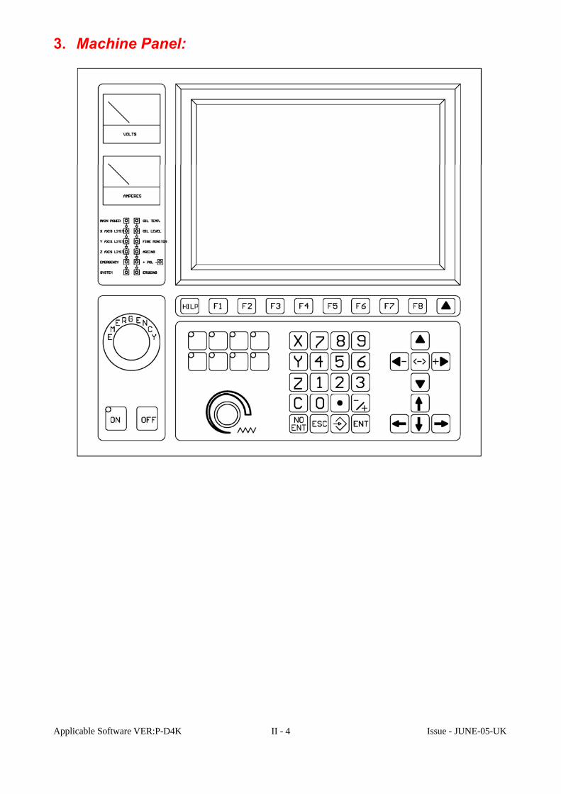
3. Machine Panel:

Applicable Software VER:P-D4K Issue - JUNE-05-UK
II - 5
4. Power Switch/ Button: “Main-Power-Switch” (Isolator) With this switch ON, the PC be ON. “Power-ON-Button” (Power Enable) After the PC has booted, press to enable Sparking Power and Servo Power. “Power-OFF-Button” Sparking Power & Servo Power are turned off when the is
pressed.
Applicable Software VER:P-D4K Issue - JUNE-05-UK
II - 6
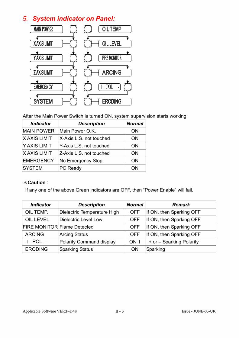
5. System indicator on Panel:
After the Main Power Switch is turned ON, system supervision starts working:
Indicator Description NormalMAIN POWER Main Power O.K. ON X AXIS LIMIT X-Axis L.S. not touched ON Y AXIS LIMIT Y-Axis L.S. not touched ON X AXIS LIMIT Z-Axis L.S. not touched ON EMERGENCY No Emergency Stop ON SYSTEM PC Ready ON *Caution: If any one of the above Green indicators are OFF, then “Power Enable” will fail.
Indicator Description Normal Remark OIL TEMP. Dielectric Temperature High OFF If ON, then Sparking OFF OIL LEVEL Dielectric Level Low OFF If ON, then Sparking OFF FIRE MONITOR Flame Detected OFF If ON, then Sparking OFF ARCING Arcing Status OFF If ON, then Sparking OFF + POL - Polarity Command display ON 1 + or – Sparking Polarity ERODING Sparking Status ON Sparking

Applicable Software VER:P-D4K Issue - JUNE-05-UK
II - 7
Aux. Function ON/OFF on Panel Dielectric Level & Temperature Supervision ON/OFF button 1. Securing dielectric level & Temperature during sparking. 2. Enabled automatically after system Start-up. 3. Sparking turned OFF as soon as alarm occurs. 4. Alarm Indicator ON & Buzzer operates indicating alarm. 5. After alarm problem is cleared, press “ENT” key to clear alarm, “START” button can then be pressed to continue sparking. Indicator for Oil Over-Temperature Indicator for Oil Level Low Flame Supervision ON/OFF button 1. Flame detection during sparking. 2. Enabled automatically after system Start-up. 3. Sparking turned OFF as soon as alarm occurs. 4. Alarm Indicator ON & Buzzer indicating alarm. 5. After alarm problem is cleared, press “ENT” key to clear alarm, “START” button can then be pressed to continue sparking. Indicator for flame Detection Arcing Supervision ON/OFF button 1. Arc detection during sparking. 2. Enabled automatically after system Start-up. 3. Sparking turned OFF as soon as alarm occurs. 4. Alarm Indicator ON & Buzzer indicating alarm. 5. After alarm problem is cleared, press “ENT” key to clear alarm, “START” button can then be pressed to continue sparking. Indicator for Arc Detection
Applicable Software VER:P-D4K Issue - JUNE-05-UK
II - 8
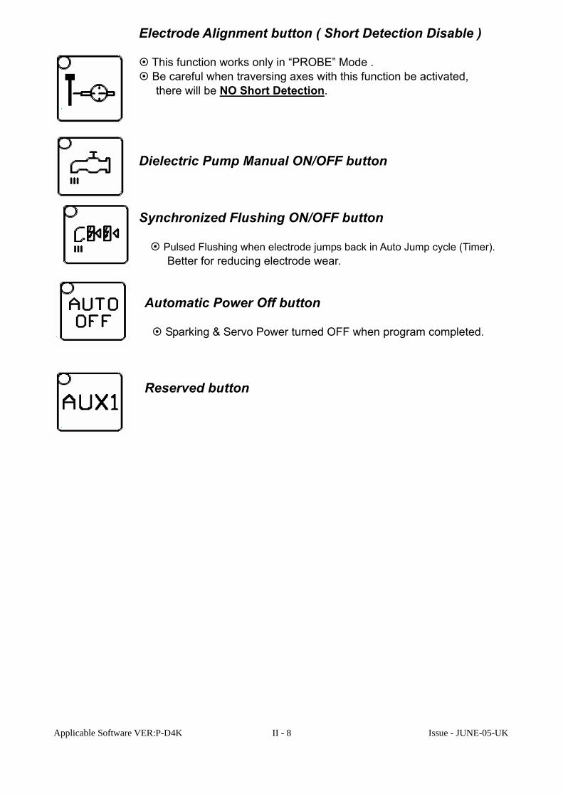
Electrode Alignment button ( Short Detection Disable ) This function works only in “PROBE” Mode . Be careful when traversing axes with this function be activated, there will be NO Short Detection. Dielectric Pump Manual ON/OFF button Synchronized Flushing ON/OFF button Pulsed Flushing when electrode jumps back in Auto Jump cycle (Timer). Better for reducing electrode wear. Automatic Power Off button Sparking & Servo Power turned OFF when program completed. Reserved button

Applicable Software VER:P-D4K Issue - JUNE-05-UK
II - 9
ON
6. System Start-up: 1.Switch ON (in C.W. direction) the Main-Power-Switch that located on
the right side of Cabinet. Power for PC will be activated. 2.After PC Self-Diagnosis. The PC Monitor will display:
3.Press Function Key “F1” to initiate the EDM PC-Base Control System. 4.Press the “Power-ON-Button” to enable the Power for Sparking & Servo.

Applicable Software VER:P-D4K Issue - JUNE-05-UK
II - 10
5. System Start-up O.K.

Applicable Software VER:P-D4K Issue - JUNE-05-UK
II - 11
7. Remote Control Box:
STOP START
Z-Z+
Y+
X-
X+
Y-SPEED

Applicable Software VER:P-D4K Issue - JUNE-05-UK
II - 12
Sparking ON
During Sparking, press Sparking OFF, resume Sparking ON. Sparking OFF, Stop Program-Run, “SHORT-Supervision” disable in
Manual Mode. When a Short happens between electrode and workpiece, axes moving is inhibited. Press “STOP” button and Axis +/- button together to move out of “Short” status. (Normally, “STOP” & “Z+” pressed together).
Sparking Off: After "STOP" key is pressed,
Press "ESC" key, to activate the "Sparking Off". Electrode Manual traverse Up Electrode Manual traverse Down Electrode Manual traverse in X+ direction Electrode Manual traverse in X- direction Electrode Manual traverse in Y+ direction Electrode Manual traverse in Y- direction Feed rate override for Manual traverse Emergency Stop Button Disable Power, not including Power for PC.

Applicable Software VER:P-D4K Issue - JUNE-05-UK
II - 13
☺ After “Start-Up” succeeded, PC shows the above Main Menu. System is operational for the following functions: 1.Manual Traverse: (1).Press one of the Axis keys Z+,Z-,X+,X-,Y+,Y- on Remote Control Box to move Axis. (2). Feed rate override on the Remote Control Box, shown on PC Monitor “JOG_FEED” (3). System has “SHORT” security feature, Axis-moving inhibited when “Short” occurs.
Press the “STOP” button on Remote Control Box to disable the “SHORT” security feature, with one of the Axis keys to move out of “Short”.
Be careful to press the correct Axis key when a “Short” has occurred. 2. Preset position coordinate: X or Y or Z, + or -, Number, “ENT” 3. Do the Sparking job. (1). Press “F5” Function key (RUN) or “START” button on Remote Control Box ,to
Run the Last Program to Spark. Ensure that the Position data is correct. (2). Sparking job can be interrupted by “STOP” button on Remote Control Box ,

Applicable Software VER:P-D4K Issue - JUNE-05-UK
II - 14
8. Operating Mode: 8.1 Main Menu:

Applicable Software VER:P-D4K Issue - JUNE-05-UK
II - 15
8.2 F1 MANUAL
PNC F1 MANUAL:
“F1”: “Homing” for Reference Mark Approaching, for Datum
Memory 1. Z up automatically, until Limit Switch be reached. 2. X-, Y- automatically, until Limit Switch be reached. 3. 3 Axes move back to look for the Ref. Mark of Encoder automatically,
after Ref. Mark be passed over, Axis stops. “*” mark before MACHINE_POS disappear means Ref. Mark passed
already. 4.WORK_POS displays the Actual position data. MACHINE_POS displays the Reference position to Ref. Mark.

Applicable Software VER:P-D4K Issue - JUNE-05-UK
II - 16
PNC F1 MANUAL: “F2”: “Axis Positioning” by “Manual Data Input”
1. Select Axis to move: X or Y or Z 2. Enter the new position, including sign “–“ if necessary. 3. Press “ENT” key. ORBIT-CUT (COC-280) Special Option of OBPNC or OBZNC. F 5 Pressed for COC-280 Auto. Centring.
MP_SET is only done by experienced service engineer.
After one option complete, press “▲” key,
back to the Last Menu, ready for the next job.

Applicable Software VER:P-D4K Issue - JUNE-05-UK
II - 17
PNC F2 PROBE MODE
Auto. Probing Function
1. Calibrating the electrode and aligning the work piece before Probe Mode. 2. Press the “PROBE” key on Operating Panel to disable “Short-Protection” for accurate calibration & alignment.
Electrode Alignment button ( Short Supervision Disable )
This function works only in “PROBE” Mode. Be careful when traversing axes with this function activated in
“PROBE” mode, there is no “Short” protection.

Applicable Software VER:P-D4K Issue - JUNE-05-UK
II - 18
PNC F2 F1 PROBE SURFACE ��� “F1” : Probing Edge of 3 axes for “Surface = Datum”
Description: SELECT AXIS :Choose Axis & Direction 0:DATUM 1-200 RANDOM SET :Reset “0”:Probing point = 0。 Preset 1-200 :The probing data will be transferred to the corresponding pos. data of pos. table of Pattern. RETURN POS. :Key in Back Position after Probing, then “ENT” F5 RUN :Press “F5”, start the probing START SPEED UP : : Press “START” (on Box) to increase Probing speed. TOUCH_POS (PRESET NEW DATA) : Preset new position data for Touched Edge

Applicable Software VER:P-D4K Issue - JUNE-05-UK
II - 19
PNC F2 F1 PROBE SURFACE:
“F1” : Probing Edge of 3 axes for “Surface = Datum” Measuring (Auto. Probing) for large Mould (Work piece):.
Do the "SURFACE" probing twice for each axis, the average data will show on the table of each.
"AXIS CENTER" at the upper-right corner of CRT.
Press "F7" (AXIS_POS), and key in this Axis & Centre Data to move the axis to the CENTRE point by control. Then you can reset its data be the new Datum.

Applicable Software VER:P-D4K Issue - JUNE-05-UK
II - 20
PNC F2 F2 PROBE SPK_TCH: � “F2”: “Sparking Touch” for Probing
Caution: Sparking Probing with low JOG_FEED & low LV code. SELECT AXIS: Choose Axis & Direction. F5 RUN After sparking codes, axis & direction decided,
press F5 to run Press START to start probing with sparking ON.
1. Waiting until electrode touches the work piece, sparking occurs. 2. Reduce the JOG_FEED = 0 ~ 1 3. Jogging axes with (X+,X-,Y+,Y-) keys, watching the spark, until the axes
have moved to the wanted position. 4. Press STOP to finish the sparking probing.
5. Press ▲ back to previous page, set the new Data.

Applicable Software VER:P-D4K Issue - JUNE-05-UK
II - 21
PNC F2→F3 PROBE AXIS_CEN: � “F3”: Axis Centring by probing both external sides of work piece
Move the electrode to the start point above work piece, press F 2 PROBE, then F3 (A) Procedure:: SELECT AXIS :Choose Axis & Direction 0:DATUM 1-200 RANDOM SET :Reset “0”:Probing point = 0 Preset 1-200 :The probing data will be transferred to the corresponding pos. data of pos. table of the Pattern. PROBING DISTANCE :Probing distance (B) Z UP DISTANCE :Z up position during probing (C) �F 5 RUN :Press “F5” to start probing cycle �START SPEED UP :Press “START” to increase probing speed TOUCH_POS (PRESET NEW DATA) : Preset new Axis Centre Position Data ���������� �

Applicable Software VER:P-D4K Issue - JUNE-05-UK
II - 22
PNC F2 F4 PROBE CAVE_CEN: �� “F4”: Cavity Centring by probing the Cavity internally. �
Manual traverse the electrode into the cavity, press F4 CAVE_CEN Available for square or circular cavities. Procedure:: 1. 0:DATUM 1-200 RANDOM SET :Reset “0”:Probing point = 0。 Preset 1-200 :The probing data will be transferred to the corresponding pos. data of pos. table of the Pattern. 2. Press F5 to start the auto cavity centring. Press “START” to increase probing speed 3 Eventually stop at the Cavity centre. Preset a new position data be Datum

Applicable Software VER:P-D4K Issue - JUNE-05-UK
II - 23
PNC F2 F5 PROBE CORNER:
QUADRANT CHOICE :4 corner (1,2,3,4) can be selected for probing PROBING DISTANCE :Entering the bigger rough range of X and Y distance Z UP DISTANCE :Down-Distance of Z-axis for probing 0:DATUM 1-200 RANDOM SET :Reset “0”:Probing point = 0 Preset 1-200 :The probing data will be transferred to the corresponding pos. data of pos. table of Pattern. F 5 RUN :Press “F5” to start probing cycle

Applicable Software VER:P-D4K Issue - JUNE-05-UK
II - 24
�PNC F2→F5 PROBE CORNER: After Corner probed automatically, the display shows:
XCEN. _ : YCEN. _:
Preset new data or Reset 0 , press ENT to finish the probing cycle.

Applicable Software VER:P-D4K Issue - JUNE-05-UK
II - 25
PNC F2 F6 PROBE SIDE_CEN Manual traverse electrode to the rough centre, above the work piece. Press F6 (SIDE_CEN) Procedures: 1. X PROBING DISTANCE Enter the X width + electrode radius +10 (safety clearance) 2. Y PROBING DISTANCE Enter the Y width + electrode radius +10 (safety clearance) 3. Z UP DISTANCE Down-Distance of Z-axis for probing 4. 0:DATUM 1-200 RANDOM SET:Reset “0”:Probing point = 0 Preset 1-200 :The probing data will be transferred
to the corresponding pos. data of pos. table of the Pattern.
5. F 5 RUN : Press “F5” to start probing cycle Press “START” to increase probing speed

Applicable Software VER:P-D4K Issue - JUNE-05-UK
II - 26
PNC F2 F6 PROBE SIDE_CEN:
After SIDE_CEN is finished, display shows:
XCEN. _ : YCEN. _:
Preset new data or Reset 0 , press ENT to finish the probing cycle.

Applicable Software VER:P-D4K Issue - JUNE-05-UK
II - 27
Sparking PGM Editing Mode F3 SPK_EDT
Move the cursor to somewhere of program format to preset new data: 1. PGM: Program Number 1 ~ 9999 Existing, suggesting Program Nr. in Buffer Memory:
1001 ~1025 :Copper - Steel, 1A-25A 2001 ~2060 :Graphite - Steel, 1A - 60A Entering the existing program for the wanted Current Code, and Depth command, the program can then be run. For instance: 6A from rough to fine finish, 10 MM Depth, Copper -- Steel 1) PGM: 1006 “ENT” ( loading the existing program from Memory )
2) DEPTH: -10 “ENT” 3) “START” or “RUN” ( Start Sparking ) 2.DEPTH: Sparking depth command, Range +/- 999.999
Sparking up be possible when “Depth” command higher than current WORK-POS.
3.P-BLK: Total block Nr. in program, calculated by PC itself. 4.DIRECTION: Sparking direction, defaulted “-” 5.AXIS: Sparking Axis, all of X, Y, Z be available for PNC, Z only for ZNC.

Applicable Software VER:P-D4K Issue - JUNE-05-UK
II - 28
F3 SPK_EDT:
☺ ERODING TABLE: 1.DEPTH: Depth command for each block of program. All the depth commands must be logical. 2.CODE: Sparking code command. Sparking codes stored in buffer memory. The contents can be modified when spark is off. Using the key - 、 + to search code or enter the code Nr. directly. Please refer to the “COD_EDIT”. 3.LV: Low Voltage Current command, Standard range 0-64 A. 1) Can be modified only when spark is off. 2) Bigger LV, then bigger spark, quicker, bigger gap, but rougher. Smaller LV, then smaller spark, slower, smaller gap, better surface finish. Caution: When large LV is set, the security must be paid
attention to especially Flame, Dielectric Level and Dielectric Temperature
3) Only when matched well with Ton & Toff, better working efficiency will be achieved. 4) Enter value directly or use - 、 + keys to fetch data. 4.HV: High Voltage Current 1) Range 0 - 7 2) Bigger HV, then bigger spark, quicker, bigger gap, but rougher. . Smaller HV, then smaller spark, slower, smaller gap, better surface finish. 3) Enter value directly or use - 、 + keys to fetch data. 4) Application: (1).Working with LV (2). ”HV” only, with Positive Discharge for fine finish. (3). ”HV” only, with Negative Discharge for fine finish. 5.Ton: “ON” duty of Sparking cycle.
1) Range 1 - 2000us, divided into 48steps. 2) Comparing with constant LV command, Bigger Ton, then rougher finish, bigger gap, lower wear ratio.
Smaller Ton, then better finish, smaller gap, higher wear ratio. 3) Ton set by pressing - 、 + keys to fetch data. 6.Toff: “OFF” duty of Sparking cycle. 1) Range 1 - 255 us, real data display. 2) Comparing with constant LV & Ton commands, Smaller Toff, then quicker, but debris removal not easy. Bigger Toff, then slower, but debris removal easier. 3) Enter value directly or use - 、 + keys to fetch data.

Applicable Software VER:P-D4K Issue - JUNE-05-UK
II - 29
F3 SPK_EDT: Caution: There is a rough formula between Ton vs LV for good
sparking performance:
Copper Steel, Rough eroding, Low wear-ratio, Ton/LV about 30 Medium eroding, medium wear, Ton/LV about 20 - 25 Finish eroding, higher wear, Ton/LV about 10 - 15
Suggesting table between LV & Ton for lower Copper electrode wear-ratio: 0 1 2 3 4 5 6 7 8 9 0 30 60 90 125 150 175 200 200 250
10 300 300 350 350 400 450 450 500 500 550 20 600 600 650 650 700 750 750 800 800 850 30 900 900 950 950 1000 1000 1000 1100 1100 110040 1200 1200 1200 1200 1300 1300 1300 1400 1400 140050 1500 1500 1500 1500 1600 1600 1600 1600 1700 170060 1800 1800 1800 1800 1800
Graphite Steel, Rough eroding, Low wear-ratio, Ton/LV about 25
Medium eroding, medium wear, Ton/LV about 15 - 20 Finish eroding, higher wear, Ton/LV about 5 - 10
Suggesting table between LV & Ton for lower Graphite electrode wear-ratio: 0 1 2 3 4 5 6 7 8 9 0 25 50 70 100 120 150 125 200 200
10 250 250 300 300 350 350 400 400 450 450 20 500 500 550 550 600 600 650 650 700 700 30 700 700 800 800 800 800 900 900 900 900 40 1000 1000 1000 1000 1100 1100 1100 1100 1100 110050 1200 1200 1200 1200 1200 1200 1200 1200 1200 120060 1200 1200 1200 1200 1200
7.GAP: Gap Voltage setting for retracting control. 1) Range 0 – 15 2) Smaller GAP, then smaller sparking gap, quicker, not easy to
remove debris. Bigger GAP, then bigger sparking gap, slower, easier to remove debris. GAP 3) GAP data set by pressing - 、 + keys to fetch data.

Applicable Software VER:P-D4K Issue - JUNE-05-UK
II - 30
F3 SPK_EDT: 8.SPD: Speed of Auto. Jump.
1) Range 0 – 15 2) Smaller SPD, then slower jump for bigger area of electrode and
fine sparking. 3) Bigger SPD, then quicker jump for long electrode doing deep
sparking, for longer jump distance, for easier debris removal. 4) Matched well with UPD & WT, better efficiency achieved. 5) Enter data directly or use - 、 + keys to fetch data. 9.UPD: jump UP Distance 1) Range 1 – 255 steps 2) Smaller UPD, then save dry-run time. Bigger UPD, then waste longer dry-run time. 3) Enter data directly or use - 、 + keys to fetch data. 10.WT: Working Time after auto. Jump 1) Range 1 – 255 steps, WT=0 means no Auto. jump 2) Smaller WT, then shorter working time, easier for debris removal. Bigger WT, then longer working time, harder for debris removal. 3) Enter data directly or use - 、 + keys to fetch data. 11.P/N: discharge Polarity
1) “+”: Electrode be positive polarity, “-“ : Electrode be Negative polarity
2) Changing the setting by - 、 + key 12.TIME: TIME record of each block of sparking program. Calculated by
PC itself. 13.CTL: ConTroL of Z_LOCK ON/OFF for extra external Orbit Head function. 1:Orbit Head activated, 0:Orbit Head OFF “F3” : INSert 1 block in program. “F4” : DELete 1 block in program. “F5” : Feed Hold when this block finished.
“F8” : SAVE the Sparking CODE DATA to its corresponding CODE TABLE
In memory. it will overwrite the old CODE DATA in memory.

Applicable Software VER:P-D4K Issue - JUNE-05-UK
II - 31
F3 SPK_EDT: After editing, press ▲ key to exit. Press "Y" key to save new CODE data to CODE Table in memory,
then return to main menu.
Press key to not save and return to main menu..

Applicable Software VER:P-D4K Issue - JUNE-05-UK
II - 32
PNC F4 PATTERN MODE:
Press "PATTERN" for multi-cavity editing: key in the sub-program Number. now you can set up max. 20 sets of multi-cavity pattern forms and be stored in memory. Pressing "ENT" key to enter PATTERN programming menu to start editing
1、 For multi-cavity sparking, editing the Sparking Codes and Depth. 2、 F4 to edit the multi cavity sparking position pattern and sparking types. 3、 There are some fixed patterns available. (AUTO_CAV). 4、 After pattern editing finished, press ▲ , back to previous page. 5、 Press F5 to run the multi-cavity sparking.

Applicable Software VER:P-D4K Issue - JUNE-05-UK
II - 33
PNC F4 PATTERN MODE:
1、Follow the dialogue to edit the Pattern mode 2、The POS. table of pattern (Max. 200 POS.) will be positioning & sparking. 3、Caution:When sparking, the Z POS. in the pattern POS. table is the start sparking point, and the DEPTH in Sparking PGM will be the distance to spark.(Incremental) 4、The POS. table can be random editing or edited by F8 AUTO_CAV into fixed pattern. 5、Press F8 for fixed pattern POS. editing. 6、The multi-cavity sparking is available on different planes as follows:

Applicable Software VER:P-D4K Issue - JUNE-05-UK
II - 34
PNC F4 PATTERN MODE:
Pattern POS. editing: Cursor moved to "POS.(X,Y,Z) ENT", the pattern POS. table will appear. F1-F8 for functions: Paging any NO. of table, editing random data or editing with any functionsF1-F8. 1、 MARK ALL:Selecting whole table for POS. editing. 2、 MARK ONE:Selecting the chosen cavity NO.(cursor POS.) for POS. editing. 3、 MARK INS:Inserting one POS. as the chosen cavity NO.(cursor POS.) before it. 4、 MARK DEL:Deleting the chosen cavity NO.(cursor POS.). 5、 DATA SET:Entering new POS. to marked data. 6、 INC DATA:Adding the same data to all marked original data. 7、 DATA INC:Adding incremental to all marked data one by one. (The 1st marked
one no change) 8、 AUTO CAV:Fixed pattern POS. editing. *** Moving the cursor to the wanted start cavity NO. Press F8 for fixed pattern POS. editing.

Applicable Software VER:P-D4K Issue - JUNE-05-UK
II - 35
PNC F4 PATTERN MODE:
PATTERN with AUTO_CAV (fixed pattern cycle): 1、 Cursor moved to "POS.(X,Y,Z) ENT", the pattern POS. table appeared with cursor. 2、 Moving cursor to wanted 1st cavity NO. of wanted pattern block. (Could be not the 1st cavity of POS. table) 3、 Press F8 (AUTO CAV) for fixed pattern cycle editing. 4、 Selecting wanted pattern cycle. 5、 Following the dialogue to edit the POS. Distance, Cavity No. etc. 6、 Press ENT ;All the new calculated POS. data will be generated into the table. 7、 Moving the cursor to the next wanted 1st cavity No. of next wanted pattern block. 8、 Repeating the same procedures 3 – 6 . 9、 Ensuring the programmed cavities POS.、NR.、Z POS. …are correct, press ▲
to finish pattern editing. Press F5 to run the pattern sparking.

Applicable Software VER:P-D4K Issue - JUNE-05-UK
II - 36
PNC F4 PATTERN MODE:
PNC F4 PATTERN POS.(X.Y.Z.) ENT.:
1、Moving the cursor to No. 1 2、Press F8 (AUTO CAV), for fixed pattern cycle editing: 3 Caution:The cursor No. is the start cav No. 4、Multi blocks of fixed pattern cycles can be edited and executed

Applicable Software VER:P-D4K Issue - JUNE-05-UK
II - 37
PNC F4 PATTERN MODE:
PNC F4 PATTERN POS.(X.Y.Z.) ENT. F8 AUTO_CAV:
F1 MATRIX F 2 PATTERN2 F 3 PATTERN3
F 4 SQUARE F5 CIRCULAR F6 LINEAR .

Applicable Software VER:P-D4K Issue - JUNE-05-UK
II - 38
PNC F4 PATTERN MODE:
Multi Blocks of AUTO_CAV editing:

Applicable Software VER:P-D4K Issue - JUNE-05-UK
II - 39
PNC F4 PATTERN POS.(X.Y.Z.) ENT. F8 AUTO_CAV(F1 MATRIX:
�
1、 �Following the dialogue, Referring to the drawing to edit the pattern data.
2、 Press ENT:then back to the pattern table display automatically. The calculated new POS. data will be inserted into the table like following,
�
�

Applicable Software VER:P-D4K Issue - JUNE-05-UK
II - 40
PNC F4 PATTERN F5 RUN: To Finish pattern editing, press ▲ out of the pattern POS. table display, Rechecking the CAVE NR., Z POS. DURING MOVING, ERODING START POINT, WORK TYPE, BLK_SET, CAVE_SET, Press F5 to RUN the pattern machining:
Press F5 , Dialogue shows:
“ 1:FROM BEGINING, 2:SET BLK_NR,CAVE_NR:1” 1、 Press "1 + ENT" to spark from cavity NO. 1 of pattern table. 2、 Press "2 + ENT" to select BLK_NR. and CAVE NR. for sparking.

Applicable Software VER:P-D4K Issue - JUNE-05-UK
II - 41
PNC F4 PATTERN F5 RUN: Display of pattern machining:
1、 PNC pattern machining can be interrupted by pressing STOP on
the remote control box temporary。Pressing ESC for sparking OFF。
2、 During interruption, Z-axis can be moved up/down, X & Y can be moved away for intermediate check of sparking。
3、 Press START of remote control box, X & Y axes will be moved back to interrupted position firstly, then Z down to resume sparking。

Applicable Software VER:P-D4K Issue - JUNE-05-UK
II - 42
PNC F4 PATTERN POS.(X.Y.Z.) ENT. F8 AUTO_CAV(F1 MATRIX:
PNC F4 PATTERN POS.(X.Y.Z.) ENT. F8 AUTO_CAV(F2 PATTERN2:
�

Applicable Software VER:P-D4K Issue - JUNE-05-UK
II - 43
PNC F4 PATTERN POS.(X.Y.Z.) ENT. F8 AUTO_CAV F3 PATTERN3:
PNC F4 PATTERN POS.(X.Y.Z.) ENT. F8 AUTO_CAV F4 SQUARE:
�

Applicable Software VER:P-D4K Issue - JUNE-05-UK
II - 44
PNC F4 PATTERN POS.(X.Y.Z.) ENT. F8 AUTO_CAV F5 CIRCULAR:
PNC F4 PATTERN POS.(X.Y.Z.) ENT. F8 AUTO_CAV F6 LINEAR:
Operating procedure: 1. Editing program : Depth, Sparking Code, AUX. Function .
2. Editing Pattern for multi-Cavities machining with PNC.
3. Pattern Program executed.

Applicable Software VER:P-D4K Issue - JUNE-05-UK
II - 45
F5 RUN MODE
�
1﹑ After electrode and work piece are aligned, sparking program edited. Press F5 for single cavity sparking.
2、 During sparking, when security system finds something wrong, sparking will be turned OFF automatically. Only when the fault is cleared, press ENT to erase the error status(latch), then press START to resume sparking.
3﹑For PNC, intermediate stop by pressing STOP , then ESC for sparking off. 4﹑For ZNC, only need to press STOP for sparking off. 5﹑START of Remote Control Box for sparking ON & Resume working.

Applicable Software VER:P-D4K Issue - JUNE-05-UK
II - 46
F5 RUN
Single Cavity sparking can be started from any Block No.

Applicable Software VER:P-D4K Issue - JUNE-05-UK
II - 47
F6 AUX. SET Mode AUXiliary sparking function SETting Contents of each AUX edited by pressing - 、+ set to toggle switch.
END_UP: Z UP or not after program END. MAX : Up to Limit Switch. STAR : Up to STARt position of program. NO : NO Z Up IN_DST. : DIStance to MIN._POS of sparking job for slow down. Range 5steps. SEN_SET: SENsitivity of retracting. Range 0 – 255. Larger SEN_SET, more sensitive to retract for debris removal, slower machining. Smaller SEN_SET, less sensitive to retract for debris removal, better machining. BEEP: Buzzer off delay ON / OFF control.
System activates alarm buzzer after PGM_END or malfunction encountered to alert operator.
ON : Beeps until any key on panel be pressed. OFF: Beeps for 5 second only. AUTOPUMP:Dielectric PUMP AUTOmatically ON with Sparking ON. ON : PUMP ON with Sparking ON. OFF: PUMP NOT ON with Sparking ON. BACK_PRO:BACK PROtection function activated when arcing occurs due to poor debris removal, sparking is turned off to prevent electrode and work piece damage. ON : BACK_PRO activated.
OFF: BACK_PRO not activated.

Applicable Software VER:P-D4K Issue - JUNE-05-UK
II - 48
ENT_LOCK: ENTry LOCKed or not during sparking. ON: program editing not allowed during sparking. OFF: program editing allowed during sparking. SCREEN: SCREEN protection mode ON/ OFF. ON: Activate Screen Protection mode, Screen background is black. OFF: Screen Protection mode not activated. Z_LOCK: Z-Axis LOCK ON / OFF during sparking. ON : Z_LOCK for external Orbit Head application. OFF: No Z_LOCK. ZXYZ/XY: For OBCUT option: Working Plane OB CODE: For OBCUT option: Working Code OB SPEED: For OBCUT option: Working Speed MATERIAL: For Future Use ROTARY_T: For Rotary Indexer option ON : Signals to & from Rotary Indexer. OFF: Normal PNC Operation.
F7 Save Mode Save the current machining data into buffer memory before power turned off

Applicable Software VER:P-D4K Issue - JUNE-05-UK
II - 49
F8 FILE_EDT Mode Sparking FILE EdiTing Mode
“F3” COD_EDIT : CODes EDITing / Eroding Table Editing
“F4” TIME_SET : TIME control enable & SET timer
“F5” PGM_DIR : ProGraM DIRectory
“F6” PGM_DEL : ProGraM DELete
“F7” PGM_COPY : ProGraM COPY

Applicable Software VER:P-D4K Issue - JUNE-05-UK
II - 50
F8 FILE_EDT F3 COD_EDIT
“F3” : CODes EDITing / Eroding Table Editing
We offer an Eroding Table Data Base for your reference to choose for working.
You can optimize its contents or setup your own combination be a new code for your specific application. We suggest you divide the codes into groups according to material & LV for easier recall.
CODE No. range 001- 499 , according to material: 001 ~ 199 Copper Electrode - Steel 200 ~ 299 Graphite Electrode - Steel 300 ~ 309 Steel Electrode - Steel 310 ~ 319 Copper Electrode - Tungsten 320 ~ 499 Reserved for Users

Applicable Software VER:P-D4K Issue - JUNE-05-UK
II - 51
Copper Electrode --- Steel: 001 ~ 009 : 1 A ~ 3 A HV 010 ~ 109 : 1 A ~ 9 A LV └── > 1st digit: bigger number, bigger gap, lower wear ratio, used for deeper machining └──> Every 10 steps with same LV & different wear ratio 110 ~ 114 : 12 A LV with different wear ratio └── > 1st digit: bigger number, bigger gap, lower wear ratio, used for deeper machining └── > Every 5 steps with same LV, with different wear ratio 115 ~ 119 : 15A LV with different wear ratio 120 ~ 124 : 20A LV with different wear ratio 125 ~ 129 : 25A LV with different wear ratio 130 ~ 134 : 30A LV with different wear ratio 135 ~ 139 : 35A LV with different wear ratio 140 ~ 144 : 40A LV with different wear ratio 145 ~ 149 : 45A LV with different wear ratio 150 ~ 154 : 50A LV with different wear ratio 155 ~ 159 : 55A LV with different wear ratio 160 ~ 164 : 60A LV with different wear ratio 165 ~ 199 : Reserved Graphite Electrode --- Steel: 200 ~ 209 : LV 1A ~ 9A 210 ~ 214 : 10A LV with different wear ratio 215 ~ 219 : 15A LV with different wear ratio 220 ~ 224 : 20A LV with different wear ratio 225 ~ 229 : 25A LV with different wear ratio 230 ~ 234 : 30A LV with different wear ratio 235 ~ 239 : 35A LV with different wear ratio 240 ~ 244 : 40A LV with different wear ratio 245 ~ 249 : 45A LV with different wear ratio 250 ~ 254 : 50A LV with different wear ratio 255 ~ 259 : 55A LV with different wear ratio 260 ~ 264 : 60A LV with different wear ratio 265 ~ 299 : Reserved Steel Electrode --- Steel: 300 : 5 A LV 301 : 10 A LV 302 : 20 A LV 303 : 30 A LV 304 : 40 A LV 305 : 50 A LV 306 : 60 A LV 307 ~ 309 : Reserved

Applicable Software VER:P-D4K Issue - JUNE-05-UK
II - 52
F8 FILE_EDT F4 TIME_SET
“F4” : TIME control enable & SET timer
In addition to Depth control, we also can enable the “TIME_CONTROL” to finish the machining. 1.SET_TIMER shown above programming table, at right side, when TIME_CTL enabled. 2. When the last block of program be executed, program completed due to Depth reached or Set Timer runs out, dependant on which one comes first. 3. Then, Z Up or not according to END_UP of AUX._SET to finish sparking program.
TIME_SET

Applicable Software VER:P-D4K Issue - JUNE-05-UK
II - 53
F8 FILE_EDT F5 PGM_DIR
“F5”:ProGraM DIRectory

Applicable Software VER:P-D4K Issue - JUNE-05-UK
II - 54
F8 FILE_EDT F6 PGM_DEL
“F6” : ProGraM DELete
DELETE PGM_NR: key in PGM_NR,

Applicable Software VER:P-D4K Issue - JUNE-05-UK
II - 55
F8 FILE_EDT F7 PGM_COPY
“F7” : ProGraM COPY
Copy from an existing source program to a new target program. SOURCE PGM_NR : ; Key in Source PGM Nr, then “ENT” TARGET PGM_NR : ; Key in Target PGM Nr, then “ENT”

III - 1 Issue - JUNE-05-UK
III PC-Based EDM System
Program Table
(Sparking)

III - 2 Issue - JUNE-05-UK
Copper Steel
LV
A
HV
A
Ton
μs
Toff
μs
GAP V
V VDI
ROUGHNESS
μmRa
TWO GAP
2xGAP(mm)
WEAR RATIO
%
SPEED
mm3/min
0 1 2 5 45 15 0.4 0.02 15 0.2 0 1 5 5 45 17 0.7 0.02 10 0.6 0 1 10 5 45 19 0.9 0.04 6 0.9 0 1 20 10 45 20 1.0 0.06 4 1.3 0 1 40 10 45 22 1.26 0.07 1.8 1.6 0 1 80 10 45 23 1.6 0.09 0.9 1.8 0 1 100 15 45 24 1.8 0.10 0.6 1.2 0 1 125 15 45 25 2.1 0.11 0.4 0.8
LV
A
HV
A
Ton
μs
Toff
μs
GAP V
V VDI
ROUGHNESS
μmRa
TWO GAP
2xGAP(mm)
WEAR RATIO
%
SPEED
mm3/min
0 2 2 5 45 18 0.8 0.02 20 0.4 0 2 5 5 45 19 0.9 0.03 18 0.8 0 2 10 5 45 22 1.26 0.06 10 2.1 0 2 20 10 45 23 1.4 0.07 8 2.5 0 2 40 10 45 24 1.6 0.08 5 3.0 0 2 80 10 45 26 2.0 0.10 2 2.0 0 2 100 15 45 27 2.2 0.11 1.5 1.5 0 2 125 15 45 28 2.5 0.12 0.8 1.2
LV
A
HV
A
Ton
μs
Toff
μs
GAP V
V VDI
ROUGHNESS
μmRa
TWO GAP
2xGAP(mm)
WEAR RATIO
%
SPEED
mm3/min
0 3 2 5 45 19 0.9 0.02 24 0.5 0 3 5 5 45 20 1.1 0.04 21 0.9 0 3 10 10 45 22 1.28 0.06 12 2.4 0 3 20 15 45 24 1.6 0.07 8.4 2.8 0 3 40 15 45 25 1.7 0.08 5.8 3.4 0 3 80 20 45 26 2.2 0.08 2.2 2.4 0 3 100 20 45 28 2.4 0.09 1.6 1.9 0 3 125 20 45 29 2.8 0.09 1.0 1.6

III - 3 Issue - JUNE-05-UK
Copper Steel
LV
A
HV
A
Ton
μs
Toff
μs
GAP V
V VDI
ROUGHNESS
μmRa
TWO GAP
2xGAP(mm)
WEAR RATIO
%
SPEED
mm3/min
1 1 2 5 40 20 1.0 0.05 9.6 0.7 1 1 5 5 40 23 1.4 0.06 8 2.1 1 1 10 10 40 24 1.6 0.07 1.4 4.1 1 1 20 10 40 25 1.8 0.08 1 4.8 1 1 40 15 40 26 2.0 0.09 1.0 6.6 1 1 60 20 40 27 2.24 0.12 0.9 4.6 1 1 80 20 40 29 2.8 0.16 0.8 4.1 1 1 100 20 40 31 3.3 0.18 0.4 3.2
LV
A
HV
A
Ton
μs
Toff
μs
GAP V
V VDI
ROUGHNESS
μmRa
TWO GAP
2xGAP(mm)
WEAR RATIO
%
SPEED
mm3/min
2 1 2 5 40 20 1.0 0.02 9.1 0.8 2 1 5 5 40 21 1.5 0.06 7.6 1.6 2 1 10 5 40 23 1.3 0.07 6.4 4.3 2 1 20 5 40 24 1.6 0.09 4.1 5.4 2 1 40 5 40 26 1.9 0.10 2.8 7.3 2 1 80 10 40 28 2.3 0.12 1.2 12 2 1 100 10 40 29 2.5 0.13 0.8 18 2 1 125 10 40 30 3.15 0.14 0.5 14
LV
A
HV
A
Ton
μs
Toff
μs
GAP V
V VDI
ROUGHNESS
μmRa
TWO GAP
2xGAP(mm)
WEAR RATIO
%
SPEED
mm3/min
3 1 2 5 40 20 1.13 0.04 9.3 2 3 1 5 5 40 21 1.12 0.05 8.4 3 3 1 20 5 40 25 1.82 0.09 5.2 6 3 1 80 10 40 29 2.86 0.13 1.4 20 3 1 100 10 40 30 3.15 0.14 1.0 23 3 1 125 10 40 31 3.42 0.15 0.6 21

III - 4 Issue - JUNE-05-UK
Copper Steel
LV
A
HV
A
Ton
μs
Toff
μs
GAP V
V VDI
ROUGHNESS
μmRa
TWO GAP
2xGAP(mm)
WEAR RATIO
%
SPEED
mm3/min
4 2 5 5 40 22 1.42 0.07 9.6 3 4 2 10 5 40 24 1.60 0.08 8.4 4 4 2 20 5 40 27 2.24 0.10 6.1 8 4 2 40 10 40 29 2.84 0.11 4.2 18 4 2 80 10 40 30 3.15 0.13 1.8 27 4 2 100 10 40 31 3.42 0.14 1.4 28 4 2 125 20 40 32 3.76 0.15 0.8 24
4 2 150 20 40 33 4.50 0.16 0.4 21
LV
A
HV
A
Ton
μs
Toff
μs
GAP V
V VDI
ROUGHNESS
μmRa
TWO GAP
2xGAP(mm)
WEAR RATIO
%
SPEED
mm3/min
5 2 10 5 40 24 1.6 0.09 9.2 6 5 2 20 5 40 28 2.7 0.11 6.8 10 5 2 40 10 40 30 3.15 0.12 4.6 22 5 2 80 10 40 31 3.7 0.14 2.1 28 5 2 100 10 40 31 3.7 0.15 1.6 32 5 2 125 20 40 32 3.9 0.16 1.0 31 5 2 150 20 40 33 4.4 0.17 0.6 27 5 2 175 20 40 33 4.5 0.17 0.4 24
LV
A
HV
A
Ton
μs
Toff
μs
GAP V
V VDI
ROUGHNESS
μmRa
TWO GAP
2xGAP(mm)
WEAR RATIO
%
SPEED
mm3/min
6 2 10 5 40 25 1.9 0.09 9.8 11 6 2 20 5 40 27 2.24 0.12 7.8 21 6 2 40 5 40 28 2.46 0.13 5.6 27 6 2 80 10 40 30 3.15 0.15 2.6 34 6 2 100 10 40 31 3.6 0.16 1.6 38 6 2 125 20 40 31 3.8 0.17 1.2 36 6 2 150 20 40 32 4.2 0.17 0.8 34 6 2 175 20 40 33 4.5 0.18 0.6 32

III - 5 Issue - JUNE-05-UK
Copper Steel
LV
A
HV
A
Ton
μs
Toff
μs
GAP V
V VDI
ROUGHNESS
μmRa
TWO GAP
2xGAP(mm)
WEAR RATIO
%
SPEED
mm3/min
8 2 20 5 40 29 2.8 0.13 8.7 36 8 2 40 5 40 30 3.1 0.14 6.4 42 8 2 80 50 40 31 3.4 0.16 3.2 46 8 2 100 10 40 32 3.8 0.17 1.9 52 8 2 125 10 40 32 4.15 0.18 1.4 50 8 2 150 20 40 33 4.5 0.18 1 47 8 2 175 20 40 34 5.2 0.19 0.7 44 8 2 200 20 40 35 5.8 0.21 0.4 40
LV
A
HV
A
Ton
μs
Toff
μs
GAP V
V VDI
ROUGHNESS
μmRa
TWO GAP
2xGAP(mm)
WEAR RATIO
%
SPEED
mm3/min
10 2 40 5 40 31 3.2 0.14 7.6 52 10 2 80 5 40 32 3.9 0.16 4.6 57 10 2 100 5 40 32 4.2 0.18 2.4 69 10 2 125 10 40 33 4.5 0.19 2.2 79 10 2 150 10 40 34 5.2 0.20 1.7 65 10 2 175 20 40 35 5.4 0.21 1.5 53 10 2 200 20 40 36 6.3 0.21 0.8 50 10 2 250 20 40 37 6.8 0.22 0.4 48
LV
A
HV
A
Ton
μs
Toff
μs
GAP V
V VDI
ROUGHNESS
μmRa
TWO GAP
2xGAP(mm)
WEAR RATIO
%
SPEED
mm3/min
12 2 40 10 40 32 3.4 0.16 8.1 74 12 2 80 10 40 32 4.1 0.17 5.2 81 12 2 100 10 40 33 4.5 0.19 3.6 87 12 2 125 20 40 34 5.0 0.20 3.2 92 12 2 150 20 4 35 5.4 0.21 3 86 12 2 175 20 40 36 6.3 0.23 2.4 81 12 2 200 20 40 36 7.1 0.23 1 78 12 2 250 20 40 37 7.3 0.24 0.8 72

III - 6 Issue - JUNE-05-UK
Copper Steel
LV
A
HV
A
Ton
μs
Toff
μs
GAP V
V VDI
ROUGHNESS
μmRa
TWO GAP
2xGAP(mm)
WEAR RATIO
%
SPEED
mm3/min
15 2 50 10 40 32 3.9 0.17 8.6 81 15 2 100 10 40 33 4.5 0.19 4.1 96 15 2 125 20 40 35 5.2 0.21 3.4 112 15 2 150 20 40 36 6.3 0.22 3.1 105 15 2 175 20 40 38 7.1 0.23 2.6 101 15 2 200 20 40 37 7.4 0.24 1.2 98 15 2 250 20 40 38 7.8 0.25 0.8 95 15 2 300 30 40 38 8.2 0.26 0.5 91
LV
A
HV
A
Ton
μs
Toff
μs
GAP V
V VDI
ROUGHNESS
μmRa
TWO GAP
2xGAP(mm)
WEAR RATIO
%
SPEED
mm3/min
20 2 20 5 35 32 3.9 0.21 9.4 132 20 2 50 10 35 34 5.1 0.23 9.0 139 20 2 100 10 35 36 6.3 0.24 5.2 146 20 2 150 20 35 37 7.2 0.27 4.1 158 20 2 200 20 35 38 8.1 0.29 1.8 155 20 2 250 20 35 39 9.0 0.30 1.2 151 20 2 300 30 35 40 10.1 0.32 0.8 144 20 2 350 30 35 41 11.4 0.34 0.4 142
LV
A
HV
A
Ton
μs
Toff
μs
GAP V
V VDI
ROUGHNESS
μmRa
TWO GAP
2xGAP(mm)
WEAR RATIO
%
SPEED
mm3/min
25 2 50 5 4 34 5.2 0.24 9.2 161 25 2 100 10 40 36 6.3 0.26 5.6 172 25 2 150 10 40 37 7.3 0.28 4.1 184 25 2 200 20 40 38 8.5 0.31 2.1 181 25 2 250 25 40 39 9.0 0.33 1.4 177 25 2 300 30 4 40 10.7 0.34 1.0 171 25 2 350 30 40 41 11.0 0.35 0.7 165 25 2 400 30 40 42 12.5 0.36 0.3 161

III - 7 Issue - JUNE-05-UK
Copper Steel
LV
A
HV
A
Ton
μs
Toff
μs
GAP V
V VDI
ROUGHNESS
μmRa
TWO GAP
2xGAP(mm)
WEAR RATIO
%
SPEED
mm3/min
30 2 100 10 40 38 7.0 0.27 6.4 196 30 2 150 10 40 38 7.5 0.30 5.2 214 30 2 200 20 40 39 8.6 0.32 2.3 222 30 2 250 20 40 39 9.9 0.35 1.6 213 30 2 300 30 40 40 11 0.36 1.2 210 30 2 350 30 40 40 11.5 0.37 0.9 206 30 2 400 40 40 41 12 0.38 0.6 201 30 2 450 40 40 41 11.2 0.40 0.4 195
LV
A
HV
A
Ton
μs
Toff
μs
GAP V
V VDI
ROUGHNESS
μmRa
TWO GAP
2xGAP(mm)
WEAR RATIO
%
SPEED
mm3/min
35 2 100 10 40 39 8 0.28 6.7 232 35 2 200 20 40 40 8.2 0.31 3.2 264 35 2 250 20 40 40 8.9 0.33 1.8 287 35 2 300 20 40 41 10.3 0.36 1.4 272 35 2 350 30 40 41 11.6 0.38 1.0 269 35 2 400 30 40 42 12.1 0.40 0.8 263 35 2 450 40 40 42 12.4 0.41 0.6 258 35 2 500 40 40 43 13 0.43 0.3 254
LV
A
HV
A
Ton
μs
Toff
μs
GAP V
V VDI
ROUGHNESS
μmRa
TWO GAP
2xGAP(mm)
WEAR RATIO
%
SPEED
mm3/min
40 2 200 20 40 40 9 0.32 4.6 291 40 2 250 20 40 41 9.6 0.34 2.6 314 40 2 300 30 40 41 10.7 0.37 1.8 326 40 2 3.5 30 40 42 11.9 0.39 1.2 317 40 2 400 30 40 42 12.8 0.41 1.0 311 40 2 450 30 40 43 13.1 0.42 0.8 3.5 40 2 500 40 40 43 14 0.44 0.5 297 40 2 550 40 40 44 15.1 0.47 0.2 292

III - 8 Issue - JUNE-05-UK
Copper Steel
LV
A
HV
A
Ton
μs
Toff
μs
GAP V
V VDI
ROUGHNESS
μmRa
TWO GAP
2xGAP(mm)
WEAR RATIO
%
SPEED
mm3/min
45 2 200 17 40 41 10 0.33 4.8 316 45 2 300 18 40 41 10.6 0.36 2.3 347 45 2 350 19 40 42 11 0.38 1.7 345 45 2 400 20 40 42 12.1 0.40 1.0 341 45 2 450 21 40 43 13.6 0.42 0.9 336 45 2 500 22 40 43 14.3 0.43 0.7 332 45 2 550 22 40 44 15.6 0.46 0.5 326 45 2 600 23 40 44 16.4 0.49 0.2 321
LV
A
HV
A
Ton
μs
Toff
μs
GAP V
V VDI
ROUGHNESS
μmRa
TWO GAP
2xGAP(mm)
WEAR RATIO
%
SPEED
mm3/min
50 2 300 17 40 42 11 0.37 3 388 50 2 350 22 40 43 11.8 0.39 1.3 391 50 2 400 19 40 43 12.9 0.41 0.9 386 50 2 450 19 40 44 14 0.43 0.7 383 50 2 500 20 40 44 14.9 0.45 0.5 379 50 2 550 21 40 45 16.9 0.47 0.4 372 50 2 600 21 40 45 18 0.51 0.2 364 50 2 650 22 40 45 >18 0.54 0.2 361
LV
A
HV
A
Ton
μs
Toff
μs
GAP V
V VDI
ROUGHNESS
μmRa
TWO GAP
2xGAP(mm)
WEAR RATIO
%
SPEED
mm3/min
55 2 300 30 40 42 12.1 0.38 3.1 407 55 2 400 40 40 43 12.9 0.40 1.6 424 55 2 450 40 40 43 13.4 0.42 0.9 428 55 2 500 40 40 44 15.1 0.44 0.7 418 55 2 550 40 4 44 15.9 0.47 0.5 407 55 2 600 40 4 45 17 0.49 0.3 402 55 2 650 40 40 45 18 0.52 0.2 397 55 2 700 40 40 45 >18 0.55 0.2 392

III - 9 Issue - JUNE-05-UK
Copper Steel
LV
A
HV
A
Ton
μs
Toff
μs
GAP V
V VDI
ROUGHNESS
μmRa
TWO GAP
2xGAP(mm)
WEAR RATIO
%
SPEED
mm3/min
60 2 400 40 40 43 14.1 0.41 2.7 446 60 2 450 40 40 44 15.3 0.43 1.8 478 60 2 500 40 40 44 16.4 0.45 1.1 481 60 2 550 40 40 45 17.8 0.48 0.9 472 60 2 600 40 40 45 18 0.50 0.7 467 60 2 650 40 40 >45 >18 0.53 0.6 461 60 2 700 40 40 >45 >18 0.56 0.3 453 60 2 800 40 40 >45 >18 0.59 0.2 450

III - 10 Issue - JUNE-05-UK
Graphite Steel
LV
A
HV
A
Ton
μs
Toff
μs
GAP V
V VDI
ROUGHNESS
μmRa
TWO GAP
2xGAP(mm)
WEAR RATIO
%
SPEED
mm3/min
1 1 10 10 50 24 1.6 0.04 6.4 4.2 1 1 20 10 50 25 1.8 0.06 5.6 5.1 1 1 30 10 50 24 1.9 0.08 5.1 5.4 1 1 40 10 50 26 2.0 0.10 4.2 6.8 1 1 50 20 50 26 2.1 0.10 3.6 6.4 1 1 60 20 50 27 2.24 0.11 2.1 5.2 1 1 7 20 5 29 2.8 0.13 1.6 4.7 1 1 80 20 50 29 2.8 0.13 1.3 4.4
LV
A
HV
A
Ton
μs
Toff
μs
GAP V
V VDI
ROUGHNESS
μmRa
TWO GAP
2xGAP(mm)
WEAR RATIO
%
SPEED
mm3/min
2 1 10 10 50 23 1.3 0.07 6.8 4.3 2 1 20 10 50 24 1.6 0.09 6.2 5.4 2 1 30 10 50 29 1.7 0.10 5.6 6.4 2 1 40 10 50 26 1.8 0.10 4.5 7.3 2 1 50 20 50 31 1.9 0.11 3.8 8.2 2 1 60 20 50 33 2.0 0.11 2.4 9.6 2 1 70 20 50 34 2.1 0.12 1.8 10.4 2 1 80 20 50 28 2.3 0.12 1.4 12
LV
A
HV
A
Ton
μs
Toff
μs
GAP V
V VDI
ROUGHNESS
μmRa
TWO GAP
2xGAP(mm)
WEAR RATIO
%
SPEED
mm3/min
3 1 10 10 50 24 1.60 0.08 7.6 4.6 3 1 20 10 50 25 1.82 0.09 5.6 7.1 3 1 30 10 50 29 2.06 0.10 5.2 12 3 1 40 10 50 27 2.24 0.11 4 16 3 1 50 20 50 31 2.38 0.12 2.8 18 3 1 60 20 50 33 2.61 0.12 2.1 20 3 1 80 20 50 29 2.86 0.13 1.6 23 3 1 100 20 50 30 3.15 0.14 1.2 27

III - 11 Issue - JUNE-05-UK
Graphite Steel
LV
A
HV
A
Ton
μs
Toff
μs
GAP V
V VDI
ROUGHNESS
μmRa
TWO GAP
2xGAP(mm)
WEAR RATIO
%
SPEED
mm3/min
4 1 10 10 40 24 1.60 0.08 9.4 6 4 1 20 10 40 27 2.24 0.10 6.13 10 4 1 30 10 40 29 2.6 0.10 5.7 14 4 1 40 10 40 29 2.84 0.11 4.8 19 4 1 60 20 40 30 3.04 0.12 3.6 24 4 1 80 20 40 30 3.15 0.13 2.0 29 4 1 100 20 40 31 3.42 0.14 1.5 31 4 1 125 20 40 32 3.76 0.15 0.9 27
LV
A
HV
A
Ton
μs
Toff
μs
GAP V
V VDI
ROUGHNESS
μmRa
TWO GAP
2xGAP(mm)
WEAR RATIO
%
SPEED
mm3/min
5 2 20 20 40 28 2.8 0.11 6.4 14 5 2 30 20 40 28 3.0 0.12 5.7 17 5 2 40 20 40 30 3.15 0.12 4.6 23 5 2 60 20 40 30 3.2 0.13 3.4 26 5 2 80 20 40 31 3.4 0.14 2.1 33 5 2 100 20 40 31 3.7 0.15 1.6 34 5 2 125 20 40 32 3.9 0.16 1.0 31 5 2 150 20 40 33 4.4 0.17 0.6 29
LV
A
HV
A
Ton
μs
Toff
μs
GAP V
V VDI
ROUGHNESS
μmRa
TWO GAP
2xGAP(mm)
WEAR RATIO
%
SPEED
mm3/min
6 2 20 20 40 28 2.9 0.12 6.8 18 6 2 30 20 40 28 3.1 0.12 6.7 23 6 2 40 20 40 30 3.2 0.13 4.1 29 6 2 60 20 40 30 3.3 0.14 2.4 31 6 2 80 20 40 31 3.7 0.15 1.6 35 6 2 100 20 40 31 3.8 0.16 1.2 37 6 2 125 20 40 32 4.1 0.17 0.8 34 6 2 150 20 40 33 4.5 0.18 0.6 32

III - 12 Issue - JUNE-05-UK
Graphite Steel
LV
A
HV
A
Ton
μs
Toff
μs
GAP V
V VDI
ROUGHNESS
μmRa
TWO GAP
2xGAP(mm)
WEAR RATIO
%
SPEED
mm3/min
8 2 20 20 40 29 2.8 0.12 7.8 42 8 2 30 20 40 31 3.0 0.13 7.2 45 8 2 40 20 40 30 3.1 0.14 4.4 51 8 2 60 20 40 33 3.2 0.15 3.2 54 8 2 80 20 40 31 3.4 0.16 1.7 59 8 2 100 20 40 32 3.8 0.17 1.3 67 8 2 125 20 40 32 4.5 0.18 0.9 63 8 2 150 20 40 33 4.5 0.19 0.6 58
LV
A
HV
A
Ton
μs
Toff
μs
GAP V
V VDI
ROUGHNESS
μmRa
TWO GAP
2xGAP(mm)
WEAR RATIO
%
SPEED
mm3/min
10 2 20 20 40 30 3.1 0.13 8.2 46 10 2 40 20 40 31 3.2 0.14 4.6 54 10 2 80 20 40 32 3.9 0.16 1.9 68 10 2 100 20 40 32 4.2 0.18 1.4 74 10 2 125 20 40 33 4.5 0.19 1 88 10 2 150 20 40 34 5.2 0.20 0.6 78 10 2 175 20 40 35 5.4 0.21 0.4 64 10 2 200 20 40 36 6.3 0.21 0.4 62
LV
A
HV
A
Ton
μs
Toff
μs
GAP V
V VDI
ROUGHNESS
μmRa
TWO GAP
2xGAP(mm)
WEAR RATIO
%
SPEED
mm3/min
12 2 20 20 40 33 3.3 0.14 8.9 76 12 2 40 20 40 32 3.4 0.16 4.8 84 12 2 80 20 40 32 4.1 0.17 2.1 96 12 2 100 20 40 33 4.5 0.19 1.6 104 12 2 125 20 40 34 5.0 0.20 1.2 112 12 2 150 20 40 35 5.4 0.21 0.6 108 12 2 175 20 40 36 6.3 0.23 0.6 104 12 2 200 20 40 36 7.1 0.23 0.4 98

III - 13 Issue - JUNE-05-UK
Graphite Steel
LV
A
HV
A
Ton
μs
Toff
μs
GAP V
V VDI
ROUGHNESS
μmRa
TWO GAP
2xGAP(mm)
WEAR RATIO
%
SPEED
mm3/min
15 2 40 20 40 35 3.6 0.16 5.2 97 15 2 80 20 40 37 4.2 0.18 2.3 118 15 2 100 20 40 33 4.5 0.19 1.7 126 15 2 125 20 40 35 5.2 0.21 1.3 134 15 2 150 20 40 36 6.3 0.22 0.8 132 15 2 175 20 40 38 7.1 0.23 0.6 128 15 2 200 20 40 37 7.4 0.24 0.6 124 15 2 250 20 40 38 7.8 0.25 0.4 119
LV
A
HV
A
Ton
μs
Toff
μs
GAP V
V VDI
ROUGHNESS
μmRa
TWO GAP
2xGAP(mm)
WEAR RATIO
%
SPEED
mm3/min
20 2 50 20 40 34 5.1 0.23 5.3 164 20 2 80 20 40 37 5.6 0.24 3.2 187 20 2 100 20 40 36 6.3 0.25 2.1 192 20 2 125 20 40 37 7.2 0.26 1.6 206 20 2 150 20 40 37 7.4 0.27 1.1 194 20 2 175 20 40 39 7.6 0.28 0.8 192 20 2 200 20 40 38 8.1 0.29 0.4 188 20 2 250 20 40 39 9.0 0.30 0.4 183
LV
A
HV
A
Ton
μs
Toff
μs
GAP V
V VDI
ROUGHNESS
μmRa
TWO GAP
2xGAP(mm)
WEAR RATIO
%
SPEED
mm3/min
25 2 80 20 40 39 6.1 0.25 3.6 227 25 2 100 20 40 36 6.3 0.26 2.3 236 25 2 125 20 40 39 6.8 0.27 1.7 248 25 2 150 20 40 37 7.3 0.28 1.4 240 25 2 175 20 40 41 7.6 0.31 1.1 231 25 2 200 20 40 38 8.5 0.32 0.6 221 25 2 250 20 40 39 9.0 0.33 0.4 214 25 2 300 30 40 40 10.1 0.34 0.4 210

III - 14 Issue - JUNE-05-UK
Graphite Steel
LV
A
HV
A
Ton
μs
Toff
μs
GAP V
V VDI
ROUGHNESS
μmRa
TWO GAP
2xGAP(mm)
WEAR RATIO
%
SPEED
mm3/min
30 2 100 20 40 38 6.8 0.28 2.6 251 30 2 125 20 40 37 7.0 0.28 1.8 2680 30 2 150 20 40 38 7.5 0.30 1.6 272 30 2 175 20 40 39 8.4 0.32 1.3 266 30 2 200 20 40 39 8.6 0.32 0.7 254 30 2 250 20 40 39 9.9 0.35 0.4 251 30 2 300 30 40 40 11 0.36 0.4 247 30 2 350 30 40 40 11.5 0.37 0.4 243
LV
A
HV
A
Ton
μs
Toff
μs
GAP V
V VDI
ROUGHNESS
μmRa
TWO GAP
2xGAP(mm)
WEAR RATIO
%
SPEED
mm3/min
35 2 125 20 40 37 7.0 0.28 2.4 298 35 2 150 20 40 38 7.6 0.30 1.8 312 35 2 175 20 40 39 8.0 0.31 1.4 326 35 2 200 20 40 40 8.2 0.32 0.8 311 35 2 250 20 40 40 8.9 0.33 0.4 308 35 2 300 30 40 41 10.3 0.36 0.4 303 35 2 350 30 40 41 11.6 0.38 0.4 296 35 2 400 40 40 42 12.1 0.40 0.4 291
LV
A
HV
A
Ton
μs
Toff
μs
GAP V
V VDI
ROUGHNESS
μmRa
TWO GAP
2xGAP(mm)
WEAR RATIO
%
SPEED
mm3/min
40 2 150 20 40 38 8.0 0.30 2.4 332 40 2 175 20 40 39 9.0 0.32 1.6 354 40 2 200 20 40 40 9 0.32 0.8 368 40 2 250 20 40 41 9.6 0.34 0.6 374 40 2 300 30 40 41 10.7 0.37 0.6 364 40 2 350 30 40 42 11.9 0.39 0.4 358 40 2 400 40 40 42 12.8 0.41 0.4 351 40 2 450 40 40 43 13.1 0.42 0.4 348

III - 15 Issue - JUNE-05-UK
Graphite Steel
LV
A
HV
A
Ton
μs
Toff
μs
GAP V
V VDI
ROUGHNESS
μmRa
TWO GAP
2xGAP(mm)
WEAR RATIO
%
SPEED
mm3/min
45 2 175 20 40 39 9.0 0.32 1.8 386 45 2 200 20 40 41 10 0.33 1.2 392 45 2 250 20 40 41 10 0.33 0.6 398 45 2 300 30 40 41 10.6 0.36 0.6 392 45 2 350 30 40 42 11 0.38 0.4 386 45 2 400 40 40 42 12.1 0.40 0.4 381 45 2 450 40 40 43 13.6 0.42 0.4 371 45 2 500 50 40 43 14.3 0.43 0.4 364
LV
A
HV
A
Ton
μs
Toff
μs
GAP V
V VDI
ROUGHNESS
μmRa
TWO GAP
2xGAP(mm)
WEAR RATIO
%
SPEED
mm3/min
50 2 200 20 40 44 10 0.34 1.4 412 50 2 250 20 40 41 11.2 0.36 1 426 50 2 300 30 40 42 11 0.37 0.8 413 50 2 350 30 40 43 11.8 0.39 0.6 406 50 2 400 40 40 43 12.9 0.41 0.4 393 50 2 450 40 40 44 14 0.43 0.4 383 50 2 500 50 40 44 14.9 0.45 0.4 387 50 2 550 50 40 45 16.9 0.47 0.4 381
LV
A
HV
A
Ton
μs
Toff
μs
GAP V
V VDI
ROUGHNESS
μmRa
TWO GAP
2xGAP(mm)
WEAR RATIO
%
SPEED
mm3/min
55 2 250 20 40 41 11.2 0.36 1.3 434 55 2 300 30 40 42 12.1 0.38 0.9 438 55 2 350 30 40 42 12.1 0.38 0.7 432 55 2 400 40 40 43 12.9 0.40 0.4 426 55 2 450 40 40 43 13.4 0.42 0.4 418 55 2 500 50 40 44 15.1 0.44 0.4 409 55 2 550 50 40 44 15.9 0.47 0.4 402 55 2 600 60 40 45 17 0.49 0.4 398

III - 16 Issue - JUNE-05-UK
Graphite Steel
LV
A
HV
A
Ton
μs
Toff
μs
GAP V
V VDI
ROUGHNESS
μmRa
TWO GAP
2xGAP(mm)
WEAR RATIO
%
SPEED
mm3/min
60 2 250 20 40 41 11.2 0.36 1.4 442 60 2 300 30 40 42 12.6 0.39 1.2 464 60 2 350 30 40 43 14 0.42 0.8 448 60 2 400 40 40 43 14.1 0.41 0.4 442 60 2 450 40 40 44 15.3 0.43 0.4 437 60 2 500 50 40 44 16.4 0.45 0.4 431 60 2 550 50 40 45 17.8 0.48 0.4 428 60 2 600 60 40 45 18 0.50 0.4 420

Issue - JUNE-05-UK
IV - 1
IV PC-Based EDM System
Trouble shooting

Issue - JUNE-05-UK
IV - 2
1. Modules:
Name Elements Contents Function Fault Response
PC Main Board IPC ALL-IN-ONE IPC With ECOWIN EDM firmware
No display. Display not normal. System hanging.
Input/Output Card PIC630*
I/O access between PC & Sparking Module. System monitoring.
System initiation fail. Power ON fail. System hanging. Supervision fail.
Motion Control Card PMC620*
Position Data display and counting. Servo motion control. System monitoring.
System initiation fail. Power ON fail. System hanging. No position counting or counting not normal. Axis Run-Away.
PC Module
PC Power Supply Above 200W Power supply of IPC System initiation fail. Monitor Colour display unit 14” colour CRT User-Friendly MMI No display or not normal
Keyboard Entry keyboard KB9610* For entry key-in. System initiation fail. No or wrong key-in.
I/O Card (with PC) PPC9540*
I/O with PC. POWER ON Control. Security supervision. Sparking servo output. Equivalent Sparking signal & anti-arcing signal processing.
Power ON fail. Over-Travel not normal. Supervision not normal. Sparking servo control not normal: Gap-control not stable. Sparking On, but Electrode up, not down. Poor Sparking stability.
Spark-decoding. Oscillating signal for sparking.
PDC9348*
Sparking Codes output. Sparking oscillator. Equivalent sparking control. Anti-arcing control.
Easy arcing. Always arcing. Wrong spark decodes. Wrong sparking current. Sparking On, but electrode up, not down.
Sparking Current Output PSP931*
HV output: 0 – 7 A LV output: 0 – 64 A
No HV output. LV output not normal. Always arcing.
Sparking Module
Signals Transfer PBS938*
Mother board of Sparking Module. Signals transferring. Power for driver: H +/-12 : for HV L +/-12 : for LV S +/-12 : for Servo OSVCC: for OSCillator.
No sparking current. Sparking On, but electrode up, not down or no moving.
Drive Unit Servo driver MDR-680 DC Servo Motor Driver DCV = 36 – 150
Servo Motor no moving. Motor burned out.

Issue - JUNE-05-UK
IV - 3
Name Elements Contents Function Fault Response Resistor Module
Resistors for each Limiting sparking current
60 A、120 A、 180 A、250A 300 A、、、
RPR – 64 Power Resistor Modules. (120, 180, 250, 320 …A.)
Resistor broken, sparking current lower than command.
Sparking Power L120-75A(150A) H280-5A
For Low Voltage current For High Voltage current
No LV or HV sparking current output.
Power Supply Module
Servo Power MVCC-10A (80V,140V)
For Servo driver power No servo motion.
Remote Control box
Portable line control box KEY
Manual Jog with potential. Sparking Start/Stop.
No key function.
M/C interface I/O Card
Interface between M/C & Cabinet
SCL963*
Security I/O. Linear scale signals driver.
Supervision not normal. Position counting fault. Axis run-away.
2. PC basic set-up 1). CMOS BIOS set up: Mains Switch ON, press『↓』key, entering CMOS BIOS set-up: A. Disable A 、B、C、D Diskette. B. The others same as normal PC set-up. 2). Set Up of Linear Scales for different specification: Mains switch ON, before system initiation, press ESC key, Monitor displays: A > For PNC with Scale 0.001mm type, key in X 1 then ENT key. For PNC with Scale 0.005mm type, key in X 5 then ENT key. For ZNC with Scale 0.001mm type, key in Z 1 then ENT key. For ZNC with Scale 0.005mm type, key in Z 5 then ENT key. Mains Switch OFF and ON again, it will work.

Issue - JUNE-05-UK
IV - 4
3. Fault Finding: 3.1 Mains ON, no Display on CRT Panel Indicating LEDs lit? Fuse blown? NO Missing or faulty Mains voltage input, Power cable
loosened or Phase missing. CRT Fault Checked with another CRT replacement to know CRT O.K. or not. . PC Module Fault 1). PC Power Supply 2). PC Main Board 3.2 Power ON sequence: Mains switch turned ON, PC will be ON together PC start self-diagnosing If shows “ KEYBOARD ERROR OR NO KEYBOARD PRESENT” 1. Cable of keyboard not connected? 2. Keyboard fail? CMOS BIOS SET UP “DISK BOOT FAILURE, INSERT SYSTEM DISK AND PRESS ENTER” 1. CMOS BIOS not matching? Please set up CMOS BIOS again 2. RAM/ROM Card Fail? Replaced RAM/ROM Card “System Initiation via F1” System self-diagnosis O.K. or not Output system OK signal & PC control NO ready. I/O Card PIC630*, PMC620* Fail “Push ON for Power ON” Check Panel indicating LEDs. (Refer to the following description) Pressing ON button on Panel System Start-Up O.K..

Issue - JUNE-05-UK
IV - 5
3.3 System Supervision Indicating LED Description: ON: Mains switch ON, Mains Power O.K. OFF: Mains Switch OFF or Mains Power not O.K. All the other indicating LEDs off. Check: Fuse, Mains or PPC9540* PCB fail? ON: X-axis over-travel L.S. not reached. OFF: X-axis is over-travel, Power ON blocked. Check: X Limit Switch/wiring, SK7 Connector /
Wiring, & PGM/CN10, or PPC9540* PCB fail? ON: Y-axis over-travel L.S. not reached. OFF: Y-axis is over-travel, Power ON blocked. Check: Y Limit Switch/wiring, SK8 Connector /
Wiring, & PGM/CN11, or PPC9540* PCB fail? ON: Z-axis over-travel L.S. not reached. OFF: Z-axis is over-travel, Power ON blocked. Check: Z Limit Switch/wiring, SK9 Connector /
Wiring, & PGM/CN12, or PPC9540* PCB fail? ON: Emergency Stop button not pressed down. OFF: Emergency Stop button pressed down. Check: Buttons/wiring on Panel & Remote Box? ON: PC System ready for Power ON (Sparking & Servo) OFF: PC System not ready yet, Power ON blocked. Check: 1. PCBs of PC Modules put in correct location? 2. PIC、PMC PCB fail? 3. PC Modules fail? Caution:
Power ON blocked as any one of the above green System indicating LEDs not lit up.
3.4 Position Data not Counting or counting not normal when axes moving: Possible causes:
1. Power Supply of Linear Scale. 2. Cables of Linear Scales (Scales SCL/SN1,2,3) (SCL/CN4,5,6 SK1,2,3) 3. Intermediate Signals Cable of Scales (PGM/CN4 PMC/CN1) 4. Driver PCB of Scales Signals PGM942. 5. PCB SCL963* or PMC 620*. 6. Linear Scale.
Path of counting signals of Linear Scales: Reader head Scale cable Scale connector SCL/CN1(2, 3) SCL/CN4(5, 6) SK 1 (2, 3) (PGM/CN1, 2, 3) PGM/CN4 PMC/CN1

Issue - JUNE-05-UK
IV - 6
Pin assignment of linear scales:SCL/CN1(2, 3) for X(Y, Z) axis SCL/CN1(2,3) pin 1 = DC5V SCL/CN1(2,3) pin 2 = A phase SCL/CN1(2,3) pin 3 = B phase
SCL/CN1(2,3) pin 4 = Ref. signal SCL/CN1(2,3) pin 5 = 0V SCL/CN1(2,3) pin 6 = GND
3.5 Counting repeatability: 1) Testing method: 1. Check with Dial Gauge, move to desired point: Reset “0” on both Dial-Gauge & PC
Position DATA. 2. Move axis away, then back to zero point: Compare the reading between Dial-Gauge &
Position DATA. 2) Reason of error: 1. Linear scale signal connected improperly → Please check every node: scale head →
scale cord → scale socket → SCL/CN1(2,3) → SCL/CN4(5,6) → SK1(2,3) → (PGM/CN1,2,3)
(***Especially check for contact problem***) 2. Linear scale fail.
3. PMC620* PCB fail. 3.6 Counting accuracy and compensation:
Testing method: 1. Checked with fine Dial Gauge & Block Gauge. 2. Compare the difference of 100mm travel with a few times of measuring, to get its
average. 3. Enter the average data into MP120 …MP125. 4. Check again until satisfied. 3.7 X (Y, Z) Run-Away when Power ON: Possible causes:
1. No position feedback from linear scale. 2. No Tacho feedback (TG). 3. Servo Drive (MDR- 680) fails. 4. PC Module: Counting direction incorrect, I/O PCB ( PMC –620* ) fail.
Caution: When Power ON and axis runs away, Press down the Emergency-Stop button
as soon as possible. The power of servo system will be cut off. Manually traverse the M/C table to the safe area for further remedies.

Issue - JUNE-05-UK
IV - 7
Remedies:
X (Y,Z) Axis Run-Away? Is the Position Counting correct?
Mains switch ON “F1” pressed “∆” pressed .(instead of “ON”). Enter Main Menu of system, but DO NOT Power ON. Turn the pulley of each axis by hand to check its position counting O.K. or not. No counting or counting is not normal, please refer to the last step of
fault-finding to diagnose the problem.
No Tacho (TG) feedback due to wiring?
1. Power OFF, remove PMC/CN2 connector, (for motion control) Power ON again, if still run-away, fault could be:
Tacho, Cable of Tacho, or Servo Drive MDR – 680 fail. 2. PC Module fails. 3. Path of Tacho (TG) of Servo Motor:
TG of Motor ( SK7(8,9) ( PSE/TB1 ( XMDR/CN1 –2,7 3.8 Easy arcing or always arcing:
After Power “ON” (for Sparking and Servo), Sparking-On not initiated yet, About 120V showed on V-Meter. (It’s not normal.): PCB PSP931* of Sparking Module is defective. After Power “ON” (for Sparking and Servo), Sparking-On not initiated yet, About 12V showed on V-Meter. (It’s O.K.): Possible causes:
1) Wrong sparking codes setting: Too big of Ton, or too small of Toff or GAP. 2) PCB PDC9348* of Sparking Module is defective.

Issue - JUNE-05-UK
IV - 8
3.9 Executing “Sparking-On”, Electrode moves up instead of down for machining: Sparking-On initiated, no touch yet between electrode and workpiece, No voltage exists on Volt-Meter or smaller than 120V, Electrode moves up instead of
down for machining:
No Volts, or not high enough V-meter after Sparking On � �Wrong Sparking Codes 1.LV = 0 ,HV= 0 , so no voltage out, Electrode up. � 2. SERVO too low, UPD too big, WT too small. �Power fault 1. Volt of (LV ) = DC 120V ,Volt of(HV)= DC 280V � 2. After POWER ON, Measuring Electrode “ + ” with 0V at L0 (PSP931* TB3), it should be 120V with 0V at H0 (PSP931* TB1/7), it should be 280V
3. If not, check Fuse, Mains voltage and phase, could be voltage too low or phase missing.
4. No OSC signal: PDC9348* PCB of Sparking Module fail. No Servo signal output V- meter should higher than 120V, SVO data on CRT
greater than 125 after Sparking-On, and before real sparking happens.
If SVO data on CRT < 125, then it could be: 1. Sparking Wires be short.
2. Feedback of Sparking Voltage missing. 3. PPC9540* PCB of Sparking Module fault. Wrong Servo output Volt display on V- meter higher than 120V after Sparking-On SVO display on CRT > 125, then it could be
PMC-620* PCB of PC Module fail. 4. Electrode moves up after Sparking On initiated: Press RUN to start sparking. No voltage on V-meter, electrode moves up.
4.1 Monitoring problem? Please turn off monitoring, then run sparking again If Sparking On O.K, please eliminate the monitored security problem. Otherwise go to next step. Preset sparking codes as follows, then try again.

Issue - JUNE-05-UK
IV - 9
4.2 Please input new codes for testing PGM:106 DEPTH:-1.000 P_BLK:6 DINECTION:-AXIS:Z
NR DEPTH CODE LV HV Ton Toff GAP SPD UPD WT P/N TIME CTL1 -5.000 068 6 2 175 40 2 8 4 8 + 00:00:00 0
*** *** If Sparking problem solved, please pay attention to your sparking codes editing next time. Otherwise, check next step.
4.3 Power supply voltage problem? Please check local power supply voltage specification, wiring and input are all correct? Please check voltage between each line. L1、L2、L3 L11、L22、L23 L31、L32、L33 L41、L42、L43
All should correspond to local voltage.
4.4 Please check all voltage on all transformers I/O, are they all O.K.!? PTF1 = 85*3 、 0 200、 0 55 PTF2 = 0 110 、 18 0 18 TF3 = 14 0 14*3 If Yes, it’s correct. If No, could be fuse blown or wiring missing.
4.5 PCB check Check all PCB’s are installed correctly, with no contact problems. Check all wiring, plug connectors, with no contact problems. **If necessary, remove the PCB’s, connectors, wires, plugs, then fit them again. Make sure PCB LED display light up O.K. as normal.
4.6 Good Luck!!!

Issue - JUNE-05-UK
IV - 10
5. Layout of electric cabinet:
Rig
ht si
de
Fron
t sid
e B
ack
side
Le
ft si
de

Issue - JUNE-05-UK
IV - 11
6. Maintenance Period Inspection item Method Space
Oil filled(axis movement, ball screw…etc)
Manual pull rod/auto
Quantity of dielectric Visual Door tighten check of work tank Visual Dielectric level setting check Function check Fire detect function check Function check
Daily
Extinguisher pressure check Visual
Lubricant quantity and waste oil check Waste oil retrieve Weekly
Dielectric filter check Pressure meter
Transfer belt check Visual Monthly
Air filter cotton of electric cabinet clean Visual
Extinguisher contents quantity check Scales Screw thread of electrode clean and lubricate
Clean and lubricate
Transfer belt check Replacement Door tighten check of oil tank Replacement X/y screw shaft clean and lubricate Clean and lubricate X/y/z movement confirm Function check
Six Monthly
Cooler filter clean Function check
Extinguish device precision check Extinguish device replacement
Motor carbon dioxide inspection (executed by supplier or local authorized agent)
Disassemble check
Mechanical precision measuring and revising
Measuring and revising
Annual
Knot distance inaccuracy measuring Measuring and revising *We recommend use SAE20 lubricant or equivalent oil at lubricant system. **The lubricator of lubricant system:
a. Use grease No. 0.00 only. b. Each delivery of oil is amounted to 2c.c. c. Seal the grease tank and keep it clean. d. Refill from gun only never refill from the top of reservoir. e. The tank capacity is 650c.c. f. Average flow pressure is 100kgf/cm

CNC
Wir
e ED
M S
ub-C
ontr
act
On
The
Late
st T
echn
olog
yM
achi
nes
Anot
roni
c El
ectr
oche
mic
alD
ebur
ring
Mac
hine
s (E
CD)
●Fu
ll H
igh
capa
city
Mac
hine
Sho
p in
clud
ing
fully
Aut
omat
ed 5
axis
cnc
Mill
ing,
Mul
ti ax
is C
NC
Turn
ing,
Gri
ndin
g et
c.●
Lase
r Pa
rt m
arki
ng●
CNC
CMM
insp
ectio
n●
Sale
of S
tand
ard
Elec
tric
Dis
char
ge M
achi
nes
(Man
ual,
ZNC
& C
NC)
to ta
ke c
ompo
nent
s up
to 2
500m
m x
120
0mm
x 7
00m
m.
●D
esig
n, M
anuf
actu
re &
Sal
e of
Ele
ctro
chem
ical
Deb
urri
ng M
achi
nes
(ECM
)●
Com
preh
ensi
ve A
fter
Sal
es S
ervi
ce.
●D
esig
n, M
anuf
actu
re &
Sal
es o
f ED
M &
ECM
Too
ling
and
Elec
trod
es.
●M
ulti
axis
CN
C ED
M &
ECM
Sub
-Con
trac
t Ser
vice
.●
ECM
Sub
-Con
trac
t Ser
vice
.●
Wir
e ED
M S
ub-C
ontr
act S
ervi
ce w
ith c
uttin
g ar
eas
up to
500
mm
x 3
20m
m x
420
mm
HIG
H.
●ED
M s
mal
l hol
e dr
illin
g M
achi
nes
and
Sub-
Cont
ract
Ser
vice
.●
EDM
/ECM
Con
sulta
ncy
Serv
ice.
Anot
roni
c-SK
M E
DM
sM
anua
l, ZN
C, C
NC
Anot
roni
c-O
cean
EDM
Dri
lling
Mac
hine
sM
anua
l, ZN
C, C
NC
Fully
Aut
omat
ed 5
axis
cnc
Mill
ing
Pe
rha
ps
Yo
u D
id N
ot
Re
ali
se H
ow
Mu
ch
Ha
s To
Off
er!
CNC
CMM
insp
ectio
n
Mul
ti ax
is C
NC
Turn
ing
5axi
s cn
c M
illin
g
Anot
roni
c Lt
d is
a c
ompa
ny r
egis
tere
d in
Eng
land
& W
ales
with
com
pany
num
ber
1658
055
Regi
ster
ed a
t the
abo
ve a
ddre
ss.
• V
AT n
umbe
r 38
2-16
97-3
2 •
©
cop
yrig
ht A
notr
onic
Ltd
.199
9-20
13
Uni
t 3,
Hol
lingd
on D
epot
, Ste
wkl
ey R
oad,
Sou
lbur
y,N
r. L
eigh
ton
Buzz
ard,
Bed
s., L
U7
0DF.
Eng
land
.Te
leph
one
+44
(015
25) 2
7026
1 F
ax +
44 (0
1525
) 270
235
E-M
ails
ales
@an
otro
nic.
com
Inte
rnet
http
://w
ww
.ano
tron
ic.c
om