p.c.b. s.b.c. - chris's acorns:...
TRANSCRIPT
Acorn Computers Limited, 4a Market Hill, Cambridge CB2 3W, England. Telephone 0223 312772
ACORN TECHNICAL MANUAL
System 1 Micro-Computer comprising:-
6502 C.P.U. 200,000
Keyboard 200,001
Introduction Page 1
Construction procedure 2
Power supply 13
Cassette Interface 14
Address Selection 15
Fitting EPROM's 19
Extending the system 21
P.C.B. Layouts 24
Parts list 6502 C.P.U. 25
Parts list Keyboard 27
Parts list 6502 S.B.C. 29
Circuit diagram 6502 C.P.U.Loose
Circuit diagram Keyboard Loose
© COPYRIGHT ACORN COMPUTERS LTD., 1979

INTRODUCTION
The Acorn Central Processor Unit employing the 6502 Micro Processor is a versatile circuit board which may be used in at least three ways:-
1. As a Single Board Controller with a program in the pair of 745571 PROM's or in the EPROM socket which may be 4, 8 or 16 K with single or multiple power supplies. Two RAM/IO IC's may be fitted giving 32 individually programmable JO lines and 256 bytes of RAM. 1K of further RAM may be fitted if required.
2. As a machine code Micro-computer with an 8 digit x 7 segment HEX display, HEX keyboard and a cassette interface all on a second board, which is accessed by one of the RAM/IO IC's. Programs are entered and stored in the K of user RAM space under control of a 512 byte monitor program in the 74S571's.
3. As the Central Processing Unit for a complete computing system. All the 6502 data, address and control lines leave the board via a 32 way D.I.N. connector, which will then have access via a parallel back plane to extension memory, a Visual Display Unit, floppy disc drive, etc.. The Key-Board may be retained for its cassette interface and an ASCII Key-Board will also connect on to the HEX keyboard IO port. Systems such as this are capable of supporting high level languages, e.g. BASIC or PASCAL and may be used at home, in business or in the laboratory. Powerful peripherals such as high speed printers may be interfaced and direct control of external apparatus is possible.
Included in this manual are the construction details necessary to assemble the C.P.U. board and Key-Board Kit which together form System 1. Also details on power supplies, cassette interfaces and address configurations which will be required however the Acorn is used are provided.
CONSTRUCTION PROCEDURE
Before you start
Before attempting to assemble the Acorn kit check that all the component parts are present and that none have been damaged. It is worthwhile taking a few minutes to make sure that you can identify all the components. Sometimes components will be substituted in case of supply difficulties. For instance,ten off 0.047 µF capacitors may replace the ten 0.1 µF capacitors shown on the parts list. The components substituted will in no way be detrimental to the Acorn's operation. Also some manufacturers have similar but different type numbers e.g. for the CMOS a CD4011 from R.C.A. may be replaced by an MM5611 from National Semiconductor.
For capacitors note that the value may be expressed in one of two ways:-
100 nF = 0.1 pF10 nF = 0.01 µF1 nF = 1000 pF0.1 nF = 100 pF etc.
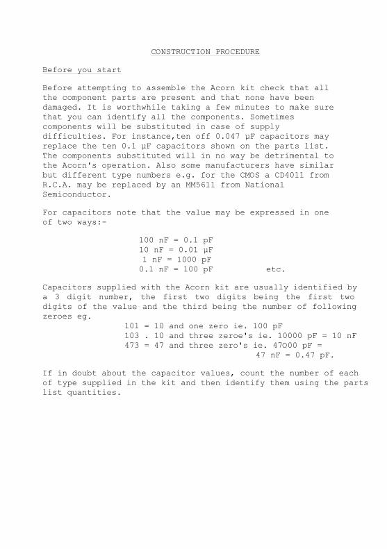
Capacitors supplied with the Acorn kit are usually identified by a 3 digit number, the first two digits being the first two digits of the value and the third being the number of following zeroes eg.
101 = 10 and one zero ie. 100 pF103 . 10 and three zeroe's ie. 10000 pF = 10 nF473 = 47 and three zero's ie. 47O00 pF =
47 nF = 0.47 pF.
If in doubt about the capacitor values, count the number of each of type supplied in the kit and then identify them using the parts list quantities.

The resistor colour chart is shown here.
The first and second bands give the resistor value and the decade band shows the number of zeros following:-
0 Black1 Brown2 Red3 Orange e.g. Yellow, Violet, Orange4 Yellow is Yellow, Violet = 4,7 and5 Green Orange = 3 zeros i.e. 000.6 Blue So the value is 47000 ohms,7 Violet i.e. 47 kilo-ohms or 47K.8 Grey9 White
The tolerance band is red for ± 2%, gold for ± 5% or silver for ± 10%, any of these are suitable for the Acorn kit.
Ensure that no components are concealed in the packing material and retain the packing material in case you have cause to return the kit.
Assembling the Acorn will require a considerable amount of soldering and a small electric soldering iron is essential with a diameter at the end of the bit not exceeding 0.1 inches. The iron should be rated between 10 and 30 watts and fine 22 guage flux cored solder should be used. If you have never soldered before we advise you not to try to assemble the Acorn without assistance as Acorn Computer Ltd. can not accept responsibility for kits which have been improperly assembled. When soldering make sure the component is well pushed on to the board as shown,use a minimum of solder and once the solder has run remove the iron.
3

Some of the integrated circuits used in the Acorn employ M.O.S. technology and they can be damaged by static electricity. As a general rule if there is no noticable static charge in the area and no nylon clothes or carpets are present all will be well. An earthed soldering iron should be used when soldering on a board containing M.O.S., I.C.'s.
The Acorn Printed Circuit Boards are double sided, through hole plated glass fibre and are manufactured to the highest standards. A layer of green solder resist ensures that accidental solder splashes do not stick to the tracks and a clearly marked white silk screen indicates component positions. Examine the two boards for faults or damage before proceeding. It is not necessary to solder through holes which connect one side of a board to the other and do not have a component lead in them and attempting to do so can break the through hole plating and thus the connection. All soldering should only be done on the opposite side of the board to the components (i.e. side 1).
Assembling the Acorn will take an hour or two, so clear a space and continue as follows.
Integrated Circuit Sockets
The Acorn is supplied with a full set of integrated circuit sockets and these should be fitted to the two circuit boards. The sockets must be fitted the right way round, on the circuit board viewing it from the top pin 1 of an I.C. is identified as shown:-

The sockets will have either a 450 chamfer for pin 1 or a semi-
Note that on the Central Processor Board IC1 is the
opposite way round to the other sockets nearby. Fit the
sockets one at a time and ensure that they are pressed
fully down with no leads bent under the socket before
first soldering two diagonally opposite pins at the
corners. Check that the socket is the right way round
and successfully fitted before soldering the rest of
the pins.
There is no need to snip off the excess of the socket
pins.
Other Components on the Boards
Resistors and capacitors are next fitted to the
circuit boards. Identify the component from the
component lists and fit it to the board. Some
capacitors will need to be fitted as shown.
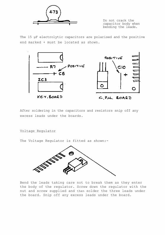
Do not crack the capacitor body when bending the leads.
The 15 µF electrolytic capacitors are polarised and the positive
end marked + must be located as shown.
After soldering in the capacitors and resistors snip off any
excess leads under the boards.
Voltage Regulator
The Voltage Regulator is fitted as shown:-
Bend the leads taking care not to break them as they enter the body of the regulator. Screw down the regulator with the nut and screw supplied and then solder the three leads under the board. Snip off any excess leads under the board.

Crystal
The crystal is fitted as shown:-
Again bend the leads away from the component body and lay the
Crystal down on the board before soldering. Snip off any excess
leads under the board.
Switch
One switch is supplied with the Acorn kit. The essential Reset
switch is also on the keyboard and so the switch supplied may be
fitted in IRQ, NM1 or duplicate RST on the Micro Computer board as
required. When fitting ensure that the flat on the switch body
faces into the board.
There is no need to fit the switch if it is not immediately
required.
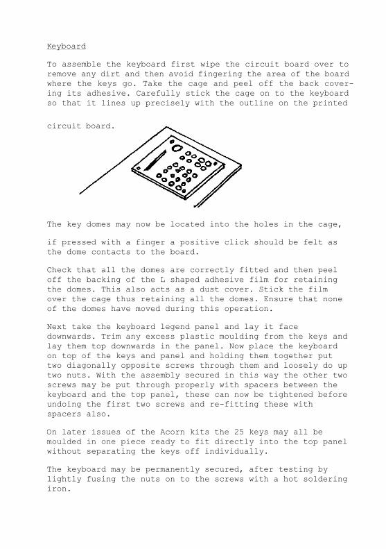
Keyboard
To assemble the keyboard first wipe the circuit board over to remove any dirt and then avoid fingering the area of the board where the keys go. Take the cage and peel off the back cover-ing its adhesive. Carefully stick the cage on to the keyboard so that it lines up precisely with the outline on the printed
circuit board.
The key domes may now be located into the holes in the cage,
if pressed with a finger a positive click should be felt as the dome contacts to the board.
Check that all the domes are correctly fitted and then peel off the backing of the L shaped adhesive film for retaining the domes. This also acts as a dust cover. Stick the film over the cage thus retaining all the domes. Ensure that none of the domes have moved during this operation.
Next take the keyboard legend panel and lay it face downwards. Trim any excess plastic moulding from the keys and lay them top downwards in the panel. Now place the keyboard on top of the keys and panel and holding them together put two diagonally opposite screws through them and loosely do up two nuts. With the assembly secured in this way the other two screws may be put through properly with spacers between the keyboard and the top panel, these can now be tightened before undoing the first two screws and re-fitting these with spacers also.
On later issues of the Acorn kits the 25 keys may all be moulded in one piece ready to fit directly into the top panel without separating the keys off individually.
The keyboard may be permanently secured, after testing by lightly fusing the nuts on to the screws with a hot soldering iron.

Display
The Acorn display has 9 digits of which the extreme left hand end one is not used. A short piece of 16 way Spectra-Strip connects the display to the keyboard. First feed the Spectra-Strip through the slot in the keyboard into the printed circuit board. Solder leads 1 and 16 first and then, if all is well, solder the rest of the leads.
Lay the display face upwards on the Spectra-Strip and solder the strip into the display. Note that the two left hand end connections on the display are not used.
The display may be pushed down on to the keyboard taking care not to over-stress the solder joints on the Spectra-Strip.

Connecting the two boards
Connection between the Micro Computer and keyboard is achieved
using a piece of 20 way 'Spectra-Strip' approximately 6 inches
long. In order that the keyboard can be mounted above the
Micro Computer the 'Spectra-Strip' must enter the keyboard from
the bottom and the Micro Computer from the top as shown:-
Before insertion check that the ends of the Spectra-Strip are
properly stripped off and then with the strip pushed well home
solder the connections to pin 1 and 20 first. If all is well
continue and solder the other 18 connections. Repeat for the
other end.
Integrated Circuits
These may now be fitted in their sockets pin 1 is identified by
either a semicircircle or a dot as shown:-

Identify the I.C. type from the components list and plug it into the appropriate socket. If the leads are splayed out press them all in together as shown until the I.C. fits easily to the socket.
Take care that no I.C. pins get bent under the I.C. when inserting and remember that I.C.1 on the C.P.U. board is the opposite way round to its neighbours.
Mounting the Boards together
Four sets of screws, nuts and spacers are provided to mount the keyboard on top of the Micro Computer board. This is advisable as it stops the interconnecting 'Spectra-Strip'from being continually flexed and strained. The screws should have their heads on the bottom of the keyboard with the nuts on the top of the C.P.U. board.
Switching On
Check that all components are properly fitted, that all IC's are in the right positions and the right way round. Check that the power supply polarity is correct, as in the section on Power Supplies following. Switch on and press the RST button which should cause the display to show eight dots. It should now be possible to examine the contents of a memory location by pressing the M key which, should result in the display of the form :-

The address of the desired location may be keyed in as four
hex digits giving for instance
Now pressing M again will display the contents of the location
as two hex digits
If the address is a byte of R.A.M. the contents may be changed
by keying in two new hex digits.
Should the kit not function switch off immediately and feel each I.
C. to see if it is exceptionally hot. If any are, check that they
are correctly inserted. Check the power connections and check that
all the assembly steps have been followed correctly. Do not
attempt to unsolder any components or sockets with 4 leads or
more as the printed circuit board may suffer. Instead cut out
faulty components so that their leads may be removed one at a
time.
The Acorn users manual should now be read from the beginning in
order to operate the micro computer fully.
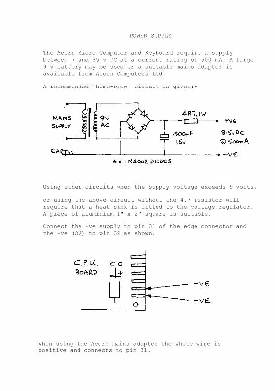
POWER SUPPLY
The Acorn Micro Computer and Keyboard require a supply between 7 and 35 v DC at a current rating of 500 mA. A large 9 v battery may be used or a suitable mains adaptor is available from Acorn Computers Ltd.
A recommended 'home-brew' circuit is given:-
Using other circuits when the supply voltage exceeds 9 volts,
or using the above circuit without the 4.7 resistor will require that a heat sink is fitted to the voltage regulator. A piece of aluminium 1" x 2" square is suitable.
Connect the +ve supply to pin 31 of the edge connector and the -ve (OV) to pin 32 as shown.
When using the Acorn mains adaptor the white wire is positive and connects to pin 31.
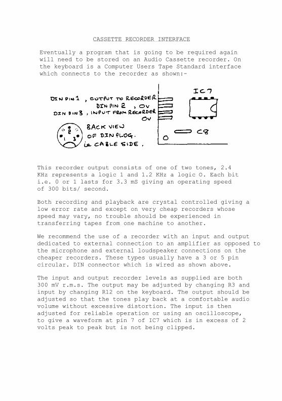
CASSETTE RECORDER INTERFACE
Eventually a program that is going to be required again will need to be stored on an Audio Cassette recorder. On the keyboard is a Computer Users Tape Standard interface which connects to the recorder as shown:-
This recorder output consists of one of two tones, 2.4 KHz represents a logic 1 and 1.2 KHz a logic O. Each bit i.e. 0 or 1 lasts for 3.3 mS giving an operating speed of 300 bits/ second.
Both recording and playback are crystal controlled giving a low error rate and except on very cheap recorders whose speed may vary, no trouble should be experienced in transferring tapes from one machine to another.
We recommend the use of a recorder with an input and output dedicated to external connection to an amplifier as opposed to the microphone and external loudspeaker connections on the cheaper recorders. These types usually have a 3 or 5 pin circular. DIN connector which is wired as shown above.
The input and output recorder levels as supplied are both 300 mV r.m.s. The output may be adjusted by changing R3 and input by changing R12 on the keyboard. The output should be adjusted so that the tones play back at a comfortable audio volume without excessive distortion. The input is then adjusted for reliable operation or using an oscilloscope, to give a waveform at pin 7 of IC7 which is in excess of 2 volts peak to peak but is not being clipped.
ADDRESS SELECTION
The Acorn has a versatile Address Mapping selection system able to support many different operating configurations. The terminology employed is that the 65,536 address's capable of being specified by AO thro' A15 are denoted by a four digit hexadecimal number in the range 0OO0 to FFFF. The most significant Hex digit, i.e. A12 thro' A15, specifies one of 16 BLOCKS'of addresses, i.e. Block 0 thro F, and these are further subdivided into pages. There are a total of 256 pages, each of 256 bytes specified by A8 thro' A15, i.e. pages OO thro' FF.
Basically the 65O2 Micro Processor requires that page FF is Read Only Memory and in particular address FFFC is used after a reset. Also it requires that page O1 is used for the stack starting at address 01 FF and extending downwards. It is usual to also make page 0O Random Access Memory as this is particularly easy to access for Scratch Pad use. Note that the bottom 32 bytes of page 00 are reserved for use by the system monitor.
A 16 pin location called ADR SEL configures the Address Map. Decoded address signals feed to this and these are connected to the Chip Select lines of the IC's on the board. Using the recommended addressing schemes block 0 and F are used for IC's on the circuit board and blocks 1 through E are left completely free for circuits external to the processor board.

low for pgs 8-F of Blk F only
low for pgs 0-7 of Blk F only
A9 low for pgs 0,1,4,5,8,9,C,D of all blocks
low for pgs 8,9,A&B of blk O only
low for pgs C,D,E&F of blk 0 only
high for pgs 0,1,2,3,C,D,E & F of blk 0 only
A8 low for pgs 0,2,4,6,8,A,C,E of all blocks
A7
CS1 of 1C8 is always on A8 i.e. high for pgs 1,3,5,7,9,B ,D & F
M/IO of 1C8 is always on A7.
C.P.U. boards from issue 2 onwards have tracks connecting the ADR SEL on side 2 of the board to provide the standard address selection scheme as shown.
Earlier boards require wire links to be fitted as appropriate before they will work. The address selection may be changed if desired by breaking these tracks and fitting new wire links.

FF
FE
FD
FC
FB
FA
F9
F8
F7
F6
F5
F4
F3
F2
Fl
FO
Note that the 512 byte ROM's appear four times. A 2O48 byte EPROM is fully decoded but if desired a 1O24 byte EPROM may be used in which case it will appear twice.
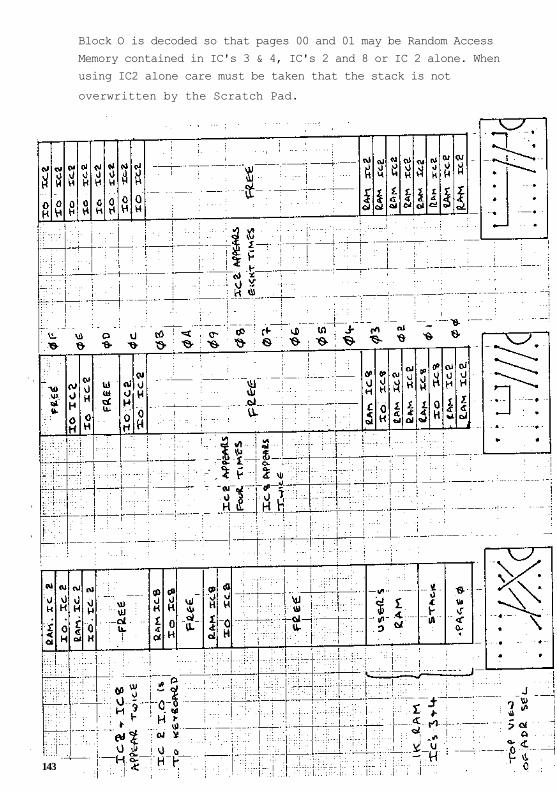
Block O is decoded so that pages 00 and 01 may be Random Access
Memory contained in IC's 3 & 4, IC's 2 and 8 or IC 2 alone. When
using IC2 alone care must be taken that the stack is not
overwritten by the Scratch Pad.
143

FITTING EPROM's
Read Only Memories with pin out systems similar to the 27O8, 2758 and 2716 EPROM's may be used for firmware storage. As supplied the board is ready for a 2716 PROM to go in the lower 2 K bytes of block F, changing the address select links as on page V, will place it in the upper 2 K bytes including the Reset Address.
To use the 2758 it is only necessary to ground pin 19. This is done by breaking a track on side 1 of the board as shown
A wire link is then soldered to the board from pin 19 to pin 12 of the ROM socket or Ov is connected to pin 1 of side B on the p.c.b. connector.
To use the 27O8 which requires +12v (Vdd) and -5v (Vbb) the track above is broken and also pin 21 is disconnected from +5v by breaking a track on side 1 as shown:-
The two extra supplies are then fed in on pins 1 and 2 of side B on the p.c.b. connector.
When a 1K byte PROM of the 27O8/2758 type is used will appear twice in the selected 2K bytes of block F.

If desired a 4K byte ROM of the 2732 type may be used in which case the track to pin 19 (A1O) is left unbroken but the track to pin 21 is broken as above and pin 21 is linked to All on pin 13 of IC 10. Neither of the block F address select links are used but instead another link is made from pin 20 of the PROM to IC9 pin 6 which is low for block F.

EXTENDING THE SYSTEM
When using the Central Processor Card with other boards in the Acorn range the voltage regulator is no longer required as a separate 5 volt supply will be in use. Pin 31 on sides A and B of the connector is then used to connect the Block 9 signal to the back plane. To modify the board in this fashion the regulator and C10 must be removed from the board and a wire link fitted from IC10 pin 15 to pin 13 of the edge connector. PCB's from issue 2 onwards have a position marked for this link from the regulator pin hole nearest the edge connector to an adjacent empty hole. C8 should be replaced by an electolytic capacitor, the one previously fitted for C10 may be used.
The C,P.U. and keyboard may be fitted in a Eurocard rack with other boards to form the Acorn system 2. The usual Acorn backplane has a 1 to 1 etc. connection all along side A of the connectors and single sided (32 way) connectors may he used.
However most p.c.b.'s will have optional connections on side B, eg. the second T0 chip on the C.P.U. board, and to use these double sided (64 way) connectors are fitted with the side B connections wire wrapped as required by the particular system configuration.
The simplest way of fitting the keyboard, which in a VDU/QWERTY keyboard system is retained for its cassette interface, is to leave it attached to the C.P.U. card by the spectra-strip and slide it into the next board location in a rack. In this way it remains connected to 1C2 on the C.P.U. board. However, keyboards from issue 2 onwards can have a 64. way connector fitted to them (if the unused pins are cut off the plug) and the CASIN, CASO and 02 pins appearing on side B may then be linked as desired on the back plane).
A QWERTY keyboard will usually be fitted to the system using IC2 on the C.P.U. board. Removing the NSA 1198 display and the 7445 I.C. frees connections to I.C. 2 allowing for a 7 bit parallel ASCII input together with a strobe connection. The 2O way spectra strip may be retained and the QWERTY keyboard wires soldered to the fingers on the C.P.U. board as shown, leaving the cassette interface as before:-

C.P.U. boards from issue 3 onwards also have provision for fitting a 20 way ribbon header plug for the I/O lines to 1C2. QWERTY keyboards may be connected via thy*' plug but the spectra-strip to the old keyboard can not be fitted with the header and so if a cassette interface is needed it must be accessed via the backplane.
To access the cassette interface via the backplane connect two wires on the back of the C.P.U. board from IC2 pin 16 to pin 19B (CASIN) and from IC2 pin 17 to pin 20B (CASO). Next connect these two pins on the back plane to pins 12B and 13B respectively of the cassette interface connector. Finally connect 02 on the cassette interface by linking pins 11B and 29A. Fit the 64 way connectors to both the C.P.U. and the cassette interface.

The usual pin connection scheme for the new keyboard
and header is as shown:-
OLD USE NEW USE SPECTRA STRIP RIBBON HEADERPIN PIN
+5v +5v 20 13
NRST NRST 19 15
dp strobe 18 17
g D6 17 19
f D5 16 20
e D4 15 18
d D3 14 16
e D2 13 14
h D1 12 12
a D0 11 10
02 02 10 8
CASIN CASIN 9 6
CASO CASO 8 4
2 7 2
1 6 5
0 5 1
C 4 3
B 3 7
A 2 9
0V 0V 1 11
It is important to realise that a monitor program is written around the keyboard and display system in use and that alter ing the hardware, environment by adding a V.D.U., QWERTY keyboard etc. will require different monitor P.R.O.M.'s.


PARTS LIST FOR 6502 C.P.U. BOARD
Sold with keyboard assembled and tested or as a kit.
P.C.B. ... Acorn Computers Ltd. pt no 200,000
ICI ... 6502 Micro Processor ... and 40 pin socket
IC2 ... 8154 RAM/IO ... and 40 pin socket
IC3 ... 2114 RAM ... and 18 pin socket
IC4 ... 2114 RAM ... and 18 pin socket
IC5 ... 74S571 Blue ROM and 16 pin socket
IC6 ... 74S571 Yellow ROM and 16 pin socket
IC7 ... 2516 EPROM. NOT SUPPLIED but 24 pin socket is.
IC8 ... 8154 RAM/IO. NOT SUPPLIED but 40 pin socket is.
IC9 ... 74LS2O ... and 14 pin socket
IC10 ... 74LS139 ... and 16 pin socket
IC11 ... 74LSO4 ... and 14 pin socket
IC12 ... 74LSO0 ... and 14 pin socket
IC13 ... LM34O-T5 ... 5v REGULATOR
XTAL ... 1MHz CRYSTAL
RESET SWITCH
SWITCH TYPE D6. ONLY ONE SWITCH SUPPLIED IN KIT
Not fitted to assembled and tested version.
IRQ SWITCH
NMI SWITCH
EUROCONNECTOR 32 way PLUG. NOT SUPPLIED
Nut and screw for IC13
ISSUE 2. JULY 79. 200,O00/P 1 of 2

R1 ... 4K7 0.33 or 0.5 w 5 or 10%
R2 ... 4K7 "
R3 ... 4K7 "
R4 ... 4K7 "
C1 ... 100nF
C2 ... 100nF
C3 ... 10nF
NOT SUPPLIED
C4 ... 10nF
C5 ... 100nF
C6 ... 100nF
C7 ... 100nF
C8 ... 100nF
C9 ... 100nF
C10 ... 15µF @ 16 v
ISSUE 2. JULY 79. 200,000/p 2 of 2
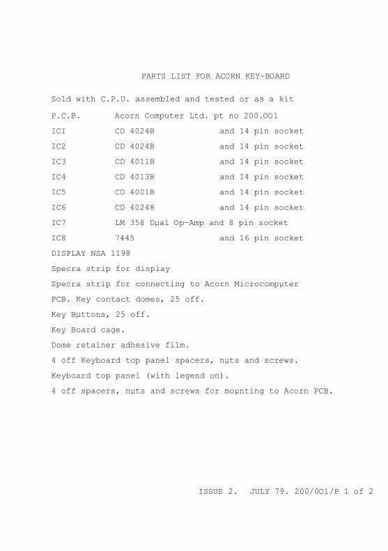
PARTS LIST FOR ACORN KEY-BOARD
Sold with C.P.U. assembled and tested or as a kit
P.C.B. Acorn Computer Ltd. pt no 200.OO1
ICI CD 4024B and 14 pin socket
IC2 CD 4024B and 14 pin socket
IC3 CD 4011B and 14 pin socket
IC4 CD 4013B and 14 pin socket
IC5 CD 4001B and 14 pin socket
IC6 CD 40248 and 14 pin socket
IC7 LM 358 Dµal Op-Amp and 8 pin socket
IC8 7445 and 16 pin socket
DISPLAY NSA 1198
Specra strip for display
Specra strip for connecting to Acorn Microcompµter
PCB. Key contact domes, 25 off.
Key Bµttons, 25 off.
Key Board cage.
Dome retainer adhesive film.
4 off Keyboard top panel spacers, nµts and screws.
Keyboard top panel (with legend on).
4 off spacers, nµts and screws for moµnting to Acorn PCB.
ISSUE 2. JULY 79. 200/0O1/P 1 of 2

R1 3K9 0.33 or 0.5 w 5 or 10%
R2 47K "
R3 4K7 "
R4 1K "
R5 10K "
R6 4K7 "
R7 4K7 "
R8 47K "
R9 4K7 "
R10 4K7 "
R11 10K "
R12 47K "
R13 4K7 "
R14 470K "
R15 4K7 "
R16 4K7 "
C1 100pF
C2 1nF
C3 1OnF
C4 1nF
C5 15µF @ 16 v
C6 100nF
C7 NOT SUPPLIED
C8 22nF
C9 100nF
C10 100nF
ISSUE 2. JULY 79. 200,001/p 2 of 2

PARTS LIST FOR ACORN SINGLE BOARD CONTROLLER
PCB ... Acorn Compµters Ltd. pt no 200,0OO
ICIq ... 6502 Micro Processor and 4O pin socket
IC2 ... 8154 RAM/IO and 4O pin socket
IC3 ... 2114 RAM NOT SUPPLIED BUT 18 pin socket is.
IC4 ... 2114 RAM " 18 "
IC5 ... 74S571 ROM " 16 "
IC6 ... 74S571 ROM " 16 "
IC7 ... 2516 EPROM " 24 "
IC8 ... 8154 RAM/IO " 40 "
IC9 ... 74LS20 and 14 pin socket
ICI0 ... 74LS139 and 16 pin socket
IC11 ... 74LSO4 and 14 pin socket
IC12 ... 74LS00 and 14 pin socket
IC13 ... LM34O-T5 ... 5 v REGULATOR
XTAL ... 82pF capacitor sµpplied instead of Crystal
RESET SWITCH Switch type D6
IRQ SWITCH Switch type D6 ONLY ONE SWITCH SUPPLIED
NMI Switch Type D6
Nut and screw for IC13

RI ... 4K7 0.33 or 0.5 w 5 or 10%
R2 ... 4K7 "
R3 ... 4K7 "
R4 ... 4K7 "
Cl ... 100nF
C2 ... 100nF
C3 ... 10nF
C4 ... 10nF NOT SUPPLIED
C5 ... 100nF
C6 ... 100nF
C- ... 100nF
C8 ... 100nF
C9 ... 100nF
C1C ... 15µF @ 16 v
ISSUE 2 . JULY 79 200 ,010/P 2 o f 2