pci based digitizer & threaded programming (lab 8
TRANSCRIPT

PCI Based Digitizer & Threaded Programming (Lab 8)
Introduction
Digitizer is a device which converts the level of an analog signal into an integer number which is closest to the real value of the signal in terms of ratio. There is a limit for the number of choices of this integer which is determined by the number of bits used for the digitization.
Example: We have a voltage signal whose range is [0, 1] volt, and we have a digitizer which has just 2 bits. We can have 4 different integer numbers with 2 bits. Each of these numbers will correspond to a range of voltage level, say, according to the following table:
Voltage Digitizer Bits Integer 0.00 - 0.25 00 0 0.25 - 0.50 01 1 0.50 - 0.75 10 2 0.75 - 1.00 11 3This kind of conversion is performed at regular intervals. Sometimes, we call this “sampling”, and the frequency of the sampling is called “sampling frequency”. Thus, digitization is not only performed in the signal domain, but also in the time domain.
Also note that, to improve the precision of the measurement:
1) We want to increase the number of bits, so each corresponding range is small enough.
2) We want to sample at high frequency, and even more importantly, we want precise sampling clock, such that the deviation between the two sampling time is small.
In this laboratory exercise, we will build a sampling ADC using a slow ADC. To do this, we will:
• Review a minimalist (kernel space) PCI device driver written for this exercise,
• Study the structure of a users space Read Out Controller (ROC) for the board,
• Study the VMOD 12E16 ADC card manufactured by Janz,
• Study a root based analysis program which implements ring-buffer and threads.
The ADC card we will be using has 12 bit voltage resolution and a typical conversion time of 15 µ sec. This specific ADC card is usually used for slow control automation which requires a few conversion per second.
However, in this exercise, we will force its limits and make a 12-bit sampling ADC out of it, by continuously starting a conversion with a clock in sync with the PCI clock of the PC we are using.

What we will be measuring is simple: The period of a scintillator pulse simulated by an arbitrary function generator.
The Measurement
We are using a digitizer board from janz: VMOD 12E16 ADC shown in the figure below.
This has MODULbus form factor. It can be fitted into a PCI carrier card to be used in a regular PC. Its “vertical” resolution is 12 bit, and we know that the lower limit for the conversion time is 15 µsec. Let us assume that we sample every time a clock signal make a transition from negative to positive value as shown with “o” in the following figure.
T = 15 µsec
The question is how accurate is this timing? If this is accurate enough, our time resolution can be much better than the sampling period, once we interpolate our signal to find a specific time. Thus, our time resolution depends directly on the stability and reproducibility of this “clock”. The sketch below is an example of changes in this “clock” signal from one period to another:
T = 17 µsec T = 13 µsec

This may happen, and it is called “jitter”. Also note that, this does not mean that “sampling frequency” is changing, because by “sampling frequency” we usually mean “the average sampling frequency.”
Now consider the following signal, which are sampled by a clock with “bad” jitter:
Timet0 t1 t2 t3 ....t4
Threshold
If we want to determine the time when the level of the signal is equal to a threshold value (from high to low), first, we have to find t0 and t1, the time of two samplings in which that kind of transition happens, then, we interpolate the time of interest (red dot). At, this point the accuracy of sampling times become important.
Accuracy of such a time resolution depends on many other factors, such as the noise level in the analog part of the board, the quality of the cables being used, and most importantly, the quality of the sampling clock used with the digitizer.
Overall, this is called the intrinsic time resolution of the system. The aim of this exercise is to measure this quantity. This will put a lower limit on timing resolution of any other measurement which is using this instrument, namely “a specification” of the system.
We will measure intrinsic time resolution of the system built in this exercise.
Building a Linux Device Driver for the PCI Card
First, we need to control the hardware. The lowest level software for this system resides in the kernel of the OS as a “device driver.” There are certain control/status registers on the ADC card. These registers can be accessed just like a regular memory access in a C program.
As an example, let us consider a 16 bit FIFO output pointed by “fifo_out_reg”. The following two-line C code will read a new 16-bit word from the card and print out the results:
uint16_t *fifo_out_reg = get_register_address_somehow(); for (i=0;i<100;i++) printf(“%d\n”, *fifo_out_reg);
Note that, although the pointer is not changing, it can print 100 different values read from the same location/register. Similarly, we can configure the hardware by writing configuration settings into the registers:
uint16_t *configuration_reg = get_register_address_somehow2();

*configuration_reg = ARM_THE_SYSTEM | MAKE_THIS_AND_THAT;
In short, once we get the registers of the device and map it to the virtual memory of the system, we can control the hardware, and gather/send data from/to it.
As you may notices all the trick lies in the hypothetical “get_register_address_somehow()” function. The PCI device driver we will be writing will do the following (follow vmod.c file shown by your tutor.)
1) Probe the card. If it does not exist, quit immediately. This is done by calling
ad1500_pci_dev = pci_get_device(VMOD_VENID, VMOD_DEVID, NULL);
function, here the first argument is the vendor ID (the ID reserved for the manufacturer “Janz”), and second argument is device ID (the ID of the PCI device -- carrier card). The device’s hardware manual must provide these. The following table is coppied from the manual of our PCI carrier:
!"#"$%" &'(#)*+!",-./0-"&12314#!!•!!$%&'%())*+'!,+-&%)(.*&+"
!/!0(+1!23.&)(.*&+4454.6)6!27! 869:!;:<!
!
!
!" )/56/177826"+295/71:852"
=>*4!(+?!.>6!-&@@&A*+'!B>(C.6%4!?6.(*@4!.>6!)6.>&?4!.>(.!5&3!+66?!.&!.(D6E!A>6+!5&3!A*4>!.&!A&%D!A*.>!.>6! )&?3@64! &+! .>6! FGHI$J,:! ,.! ?6-*+*.6@5! %6@*64! &+! .>6! $KLM<;<! NN$8GF! B&+-*'3%(.*&+! (4! *.! *4!-(B.&%5! "02OP#! 43CC@*6?:! ,-! 5&3! )(+('6! .&! B@6(%! &%! (@.6%! .>6! NN$8GFE! .>6+! .>*4! B>(C.6%! "(+?! .>6!-&@@&A*+'#!A*@@!+&.!@&+'6%!(CC@5!.&!5&3:!!
=>*4!)(+3(@!?64B%*Q64!.>6!@(.64.!96%4*&+!&-!FGHI$J,!A*.>!$KLM<;<:!,-!5&3!A%*.6!5&3%!&A+!4&-.A(%6! -&%! .>6! FGHI$J,E! 5&3! 4>&3@?! (@4&! 43CC&%.! .>6! $KLM<R<! B>*C! -&%! Q(BDA(%?!B&)C(.*Q*@*.5:! ,-! 5&3!?&+S.!346!6T.6+?6?! -6(.3%64!&-! .>6!$KLM<;<E!5&3!B(+!346! .>6!4()6!B&?6:!U&3!>&A696%!+66?!.&!?6.6B.!(+?!>(+?@6!Q&.>!H69*B6I,H4:!!
!;$" )*+<3-"=529863/1:852"->1=."=>6!Q&(%?!".>6!*+.6%-(B6!B>*C#!*4!*?6+.*-*6?!Q5!(!46.!&-!,H4!*+!$J,!B&+-*'3%(.*&+!4C(B6!(4!@*4.6?!Q6@&AV!!
)3/>5-." ?143." @532A"82"W6+?&%!,H! 0x10b5! JX7!4C(B6!%6'*4.6%!<!!H69*B6!,H! 0x9030/0x9050! JX7!4C(B6!%6'*4.6%!<!Y3Q454.6)!W6+?&%!,H! 0x13C3! JX7!4C(B6!%6'*4.6%!<TZB!Y3Q454.6)!,H! 0x02??! JX7!4C(B6!%6'*4.6%!<TZB!
!=>6! KY[! &-! .>6! Y3Q454.6)! ,H! B&?64! .>6! >(%?A(%6! %69*4*&+! &-! .>6! FGHI$J,! Q&(%?:! J3%%6+.@5! .>6!-&@@&A*+'!96%4*&+!B&?*+'!*4!346?V!!
BCD"59"C3<-E-:.7"+("
&'(#)*+"/.F8-852"
)*+#D/8A6."
<T<<! V1.0! PLX9052!<T<\! V2.0
V2.1!PLX9052!
<T<Z! V3.0! PLX9030!!=>6! $KLM<;<! C%&9*?64! (??%644! 4C(B64! .&! (BB644! .>6! @&B(@! B&+-*'3%(.*&+! %6'*4.6%4! "*+! Q&.>! ,]G! (+?!)6)&%5! %(+'6#:! =>646! %6'*4.6%4! (%6! 346?! .&! B&+-*'3%6! .>6!$KL! Q6>(9*&3%! "*:6:! (BB644! .*)64!(.! .>6!@&B(@!Q34!&%!@&B(@!Q34!B&+-*'3%(.*&+#:!=>65!(%6!+&.!.>6!4()6!(4!.>6!B&+-*'3%(.*&+!4C(B6!%6'*4.6%4:!2??*.*&+(@@5!.>%66!(??%644!4C(B64!(%6!B&+-*'3%6?!.>%&3'>!A>*B>!.>6!)&?3@64!(??%644!4C(B6!(+?!4&)6!Q&(%?I%6'*4.6%4!B(+!Q6!(BB6446?:!!
)*+"<1-."1AA/.--"/.68-:./"
B5=14"1AA/.--"->1=."
"(.-=/8>:852"
"C8G."
<! I! K&B(@!B&+-*'3%(.*&+!%6'*4.6%4!")6)&%5!)(CC6?#! \Z^[5.64!\! I! K&B(@!B&+-*'3%(.*&+!%6'*4.6%4!",]G!)(CC6?#! \Z^[5.64!Z! <! FGH_KQ34!)6)&%5!4C(B6E!@*..@6!6+?*(+!(BB644! `a[5.64!;! \! FGH_KQ34!)6)&%5!4C(B6E!Q*'!6+?*(+!(BB644! `a[5.64!`! Z! G+I[&(%?!%6'*4.6%4! `a[5.64!R! ;! _+346?! I!
!=>6!(B.3(@!(??%64464!-&%!.>646!)6)&%5!4C(B64!(%6!B&+-*'3%6?!Q5!.>6!$J,I[,GY!&-!5&3%!454.6)!696%5!.*)6! .>6!B&)C3.6%! *4!Q&&.6?:! ,-! 5&3!A*4>! .&!(BB644!&+6!&-! .>646!4C(B64E! .>6+!5&3!+66?! .&! %6(?! .>6!(B.3(@!(??%64464!-%&)!.>6!$J,!B&+-*'3%(.*&+!4C(B6b!!=>6!FGHI$J,!?&64!+&.!C%&9*?6!(+!6TC(+4*&+!8GF:!
!!!
This function returns pci device handler or NULL if there is no such card found in the PCI bus.
2) Then, we enable the pci device:
pci_enable_device(ad1500_pci_dev);
This initializes the device.
3) Every PCI device has a PCI Configuration Header (Google “PCI Configuration Header” for details.) Within this header, what is most valuable for us is Base Address Registers (BAR) in addition to the Vendor/Device ID. These registers are used to determine and allocate the type, amount and location of PCI I/O and PCI memory space that the device can use. There may be six of them for the same device. The purpose of these must be provided by the hardware manual as well. Our manual says:
!"#"$%" &'(#)*+!",-./0-"&12314#!!•!!$%&'%())*+'!,+-&%)(.*&+"
!/!0(+1!23.&)(.*&+4454.6)6!27! 869:!;:<!
!
!
!" )/56/177826"+295/71:852"
=>*4!(+?!.>6!-&@@&A*+'!B>(C.6%4!?6.(*@4!.>6!)6.>&?4!.>(.!5&3!+66?!.&!.(D6E!A>6+!5&3!A*4>!.&!A&%D!A*.>!.>6! )&?3@64! &+! .>6! FGHI$J,:! ,.! ?6-*+*.6@5! %6@*64! &+! .>6! $KLM<;<! NN$8GF! B&+-*'3%(.*&+! (4! *.! *4!-(B.&%5! "02OP#! 43CC@*6?:! ,-! 5&3! )(+('6! .&! B@6(%! &%! (@.6%! .>6! NN$8GFE! .>6+! .>*4! B>(C.6%! "(+?! .>6!-&@@&A*+'#!A*@@!+&.!@&+'6%!(CC@5!.&!5&3:!!
=>*4!)(+3(@!?64B%*Q64!.>6!@(.64.!96%4*&+!&-!FGHI$J,!A*.>!$KLM<;<:!,-!5&3!A%*.6!5&3%!&A+!4&-.A(%6! -&%! .>6! FGHI$J,E! 5&3! 4>&3@?! (@4&! 43CC&%.! .>6! $KLM<R<! B>*C! -&%! Q(BDA(%?!B&)C(.*Q*@*.5:! ,-! 5&3!?&+S.!346!6T.6+?6?! -6(.3%64!&-! .>6!$KLM<;<E!5&3!B(+!346! .>6!4()6!B&?6:!U&3!>&A696%!+66?!.&!?6.6B.!(+?!>(+?@6!Q&.>!H69*B6I,H4:!!
!;$" )*+<3-"=529863/1:852"->1=."=>6!Q&(%?!".>6!*+.6%-(B6!B>*C#!*4!*?6+.*-*6?!Q5!(!46.!&-!,H4!*+!$J,!B&+-*'3%(.*&+!4C(B6!(4!@*4.6?!Q6@&AV!!
)3/>5-." ?143." @532A"82"W6+?&%!,H! 0x10b5! JX7!4C(B6!%6'*4.6%!<!!H69*B6!,H! 0x9030/0x9050! JX7!4C(B6!%6'*4.6%!<!Y3Q454.6)!W6+?&%!,H! 0x13C3! JX7!4C(B6!%6'*4.6%!<TZB!Y3Q454.6)!,H! 0x02??! JX7!4C(B6!%6'*4.6%!<TZB!
!=>6! KY[! &-! .>6! Y3Q454.6)! ,H! B&?64! .>6! >(%?A(%6! %69*4*&+! &-! .>6! FGHI$J,! Q&(%?:! J3%%6+.@5! .>6!-&@@&A*+'!96%4*&+!B&?*+'!*4!346?V!!
BCD"59"C3<-E-:.7"+("
&'(#)*+"/.F8-852"
)*+#D/8A6."
<T<<! V1.0! PLX9052!<T<\! V2.0
V2.1!PLX9052!
<T<Z! V3.0! PLX9030!!=>6! $KLM<;<! C%&9*?64! (??%644! 4C(B64! .&! (BB644! .>6! @&B(@! B&+-*'3%(.*&+! %6'*4.6%4! "*+! Q&.>! ,]G! (+?!)6)&%5! %(+'6#:! =>646! %6'*4.6%4! (%6! 346?! .&! B&+-*'3%6! .>6!$KL! Q6>(9*&3%! "*:6:! (BB644! .*)64!(.! .>6!@&B(@!Q34!&%!@&B(@!Q34!B&+-*'3%(.*&+#:!=>65!(%6!+&.!.>6!4()6!(4!.>6!B&+-*'3%(.*&+!4C(B6!%6'*4.6%4:!2??*.*&+(@@5!.>%66!(??%644!4C(B64!(%6!B&+-*'3%6?!.>%&3'>!A>*B>!.>6!)&?3@64!(??%644!4C(B6!(+?!4&)6!Q&(%?I%6'*4.6%4!B(+!Q6!(BB6446?:!!
)*+"<1-."1AA/.--"/.68-:./"
B5=14"1AA/.--"->1=."
"(.-=/8>:852"
"C8G."
<! I! K&B(@!B&+-*'3%(.*&+!%6'*4.6%4!")6)&%5!)(CC6?#! \Z^[5.64!\! I! K&B(@!B&+-*'3%(.*&+!%6'*4.6%4!",]G!)(CC6?#! \Z^[5.64!Z! <! FGH_KQ34!)6)&%5!4C(B6E!@*..@6!6+?*(+!(BB644! `a[5.64!;! \! FGH_KQ34!)6)&%5!4C(B6E!Q*'!6+?*(+!(BB644! `a[5.64!`! Z! G+I[&(%?!%6'*4.6%4! `a[5.64!R! ;! _+346?! I!
!=>6!(B.3(@!(??%64464!-&%!.>646!)6)&%5!4C(B64!(%6!B&+-*'3%6?!Q5!.>6!$J,I[,GY!&-!5&3%!454.6)!696%5!.*)6! .>6!B&)C3.6%! *4!Q&&.6?:! ,-! 5&3!A*4>! .&!(BB644!&+6!&-! .>646!4C(B64E! .>6+!5&3!+66?! .&! %6(?! .>6!(B.3(@!(??%64464!-%&)!.>6!$J,!B&+-*'3%(.*&+!4C(B6b!!=>6!FGHI$J,!?&64!+&.!C%&9*?6!(+!6TC(+4*&+!8GF:!
!!!
So, this table tells us that, the first two BAR (BAR0 and BAR1) is used for the same purpose with two different access method. It controls the carrier card itself. We will not need them, the default should work out fine. BAR2 and BAR3 are used for two MODULbus cards carried by our PCI carrier card. Again, the purposes are identical; the difference is the endianness of the access. Intel architecture uses little endian. So, BAR2 is what we are looking for. BAR4 is used to access the on-board registers which is disabling/enabling the interrupt signals coming from the MODULbus cards. Thus, we need BAR4 as well. We call the following functions to read the relevant BAR configuration from the PCI configuration header:

bar=2; // and, then bar=4; mem_start_phys = pci_resource_start(ad1500_pci_dev, bar); mem_end_phys = pci_resource_end(ad1500_pci_dev, bar); mem_length = pci_resource_len(ad1500_pci_dev, bar);
These give the exact location and and length of the physical address of the registers of the ADC card which can be read/written as regular memory element. It should also be noted that, some registers must be read/written with specific data-width. Our beloved manual says that the registers on the ADC card can be accesses only by 16-bit operations. So, we have to use 16-bit (uint16_t*) pointers for these. Anything else will result in I/O errors (your application will receive a SIGBUS signal.)
So, this is the outline of the hidden part behind the magical “get_register_address_somehow()” function. But, it is half of the story. Two problems: 1) We are still in the kernel space, 2) The address we got is the physical address, but all the memory read/write operations must be via virtual addressing (beyond the scope of this exercise). Thus, 1) we need to map the physical address to the virtual address, so we use them via regular memory operations, 2) we send the virtual address to the user-space (as a user-space virtual address), so our application can use it directly. Thus the following steps:
4) We map the physical address to the virtual address:
mem_virtual = ioremap_nocache(mem_start_phys, mem_length);
That was easy! This much is sufficient for most of the device drivers you are using for regular computer hardware such as serial port, network cards, which are somewhat smarter than the ADC card we are using. However, for each conversion we have to write into a proper control register. If we do this in the kernel space we may have to call about 40,000 systems calls per second which is the only way to communicate with the kernel. And, a system call is an expensive call. So, we decided to handle this in the user space. In general, the disadvantage of this is, if the user is not careful, it is possible to bring down the whole system. But, for this case, there is no such risk, and we can perform some polling for near-realtime processing, without mush hit to the system performance.
5) We send the register address to the user space via “mmap” system call. This is done through a device file (will appear as /dev/vmod), and mmap(2). The mmap kernel fop (file operation) has the following key function call:
remap_pfn_range(vma, vma->vm_start, mem_start_phys >> PAGE_SHIFT, vma->vm_end-vma->vm_start, vma->vm_page_prot);
And in the use space, we call:
fd = open("/dev/vmod", O_RDWR); vmod = (uint16_t *)mmap(NULL, 0x80, PROT_READ|PROT_WRITE, MAP_SHARED, fd, 0);
From this point forward, “vmod” can be used for the array of registers dealing with the ADC card.
Read Out Controller (ROC)
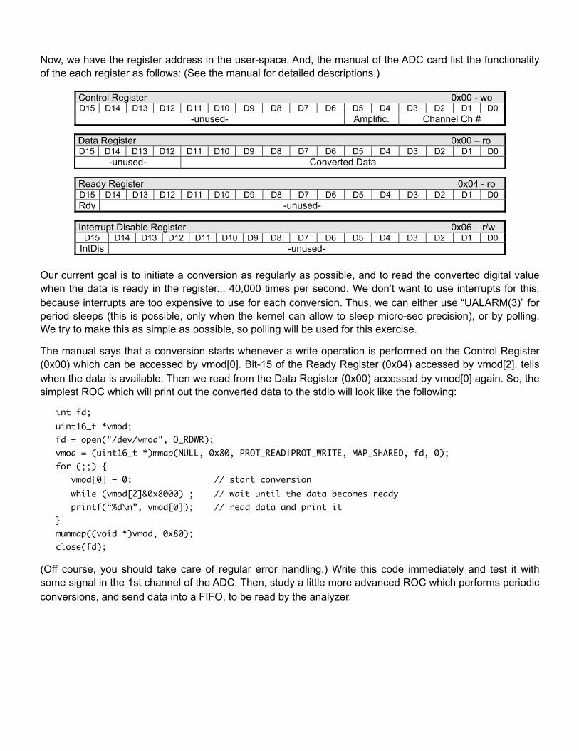
Now, we have the register address in the user-space. And, the manual of the ADC card list the functionality of the each register as follows: (See the manual for detailed descriptions.)
VMOD-12E8/16 (Hardware Manual) Conversion programming 5 - 13 .
5 Conversion programming
Please notice, that all internal registers have to be addressed with a word (16bit) access.
5.1 ADC control register A conversion can be started by writing a control word to the relative board address 0x00 (Control Register). The format of the control word is as follows: Control Register 0x00 - wo D15 D14 D13 D12 D11 D10 D9 D8 D7 D6 D5 D4 D3 D2 D1 D0
-unused- Amplific. Channel Ch #
table 9: Control Register
The selection of the corresponding ADC channel is done by data bits D0 - D3. The correspondence of channel # and bits D0 - D3 of the control register is shown in the following table:
D3 D2 D1 D0 SE Channel Diff. Channel 0 0 0 0 Ch 0 DCh0 0 0 0 1 Ch 1 DCh1 0 0 1 0 Ch 2 DCh2 .. .. .. .. .. .. 0 1 1 1 Ch 7 DCh7 1 0 0 0 Ch 8 - 1 0 0 1 Ch 9 - .. .. .. .. .. - 1 1 1 1 Ch 15 -
table 10: ADC Channel programming of Control Register
5.2 ADC data register The converted data can be read at bit D0 - D11 in the ADC data register (rel. address 0x00). The format of the data register is as follows: Data Register 0x00 – ro D15 D14 D13 D12 D11 D10 D9 D8 D7 D6 D5 D4 D3 D2 D1 D0
-unused- Converted Data
table 11: Data Register
Rev. 3.2 © JANZ Automationssysteme AG
6 - 14 VMOD-12E8/16 (Hardware Manual) Interrupt .
5.3 ADC ready register This register is to indicate an end of conversion in polling mode. The ADC ready bit can be read at bit D15 of the ADC ready register (rel. address 0x04). The format of the ADC ready register is as follows: Ready Register 0x04 - ro D15 D14 D13 D12 D11 D10 D9 D8 D7 D6 D5 D4 D3 D2 D1 D0 Rdy -unused-
table 12: Ready Register
D15 = 1 indicates, that the conversion cycle is not yet finished. D15 = 0 indicates, that the ADC data at Bit D0 - D11 in the ADC data register are valid.
6 Interrupt
The VMOD-12E8/16 is able to generate interrupts via the line INT to the MODULbus carrier board after a conversion is finished. The interrupt signal is cleared when reading the ADC data register. By default, after power on, the interrupt is enabled. If the interrupt must be disabled, bit15 of the Interrupt Disable Register has to be set. Interrupt Disable Register 0x06 – r/w
D15 D14 D13 D12 D11 D10 D9 D8 D7 D6 D5 D4 D3 D2 D1 D0 IntDis -unused-
table 13: Interrupt Disable Register
To check the interrupt setting the Interrupt Disable Register can be read: D15 = 1 end of conversion interrupt is disabled D15 = 0 interrupt is enabled In interrupt mode the converted data can be read directly from the ADC-data register after an interrupt has occurred.
If the VMOD-12E8/16 V3.x is used as replacement for the previous versions of the VMOD-12E8 or VMOD-12E16 modules, please keep in mind, that the Interrupt Disable Register does not exist there. On these old modules a jumper must be set to enable the interrupt function. So please check your software if you get unexpected interrupts. There are also
VMOD-12E8/16 versions available with disabled interrupt at reset. Please contact us if you need a VMOD-12E8/16 with the interrupt disabled by default after power on (Interrupt Disable Register is inverted!).
© JANZ Automationssysteme AG Rev. 3.2
Our current goal is to initiate a conversion as regularly as possible, and to read the converted digital value when the data is ready in the register... 40,000 times per second. We don’t want to use interrupts for this, because interrupts are too expensive to use for each conversion. Thus, we can either use “UALARM(3)” for period sleeps (this is possible, only when the kernel can allow to sleep micro-sec precision), or by polling. We try to make this as simple as possible, so polling will be used for this exercise.
The manual says that a conversion starts whenever a write operation is performed on the Control Register (0x00) which can be accessed by vmod[0]. Bit-15 of the Ready Register (0x04) accessed by vmod[2], tells when the data is available. Then we read from the Data Register (0x00) accessed by vmod[0] again. So, the simplest ROC which will print out the converted data to the stdio will look like the following:
int fd; uint16_t *vmod; fd = open("/dev/vmod", O_RDWR); vmod = (uint16_t *)mmap(NULL, 0x80, PROT_READ|PROT_WRITE, MAP_SHARED, fd, 0); for (;;) { vmod[0] = 0; // start conversion while (vmod[2]&0x8000) ; // wait until the data becomes ready printf(“%d\n”, vmod[0]); // read data and print it } munmap((void *)vmod, 0x80); close(fd);
(Off course, you should take care of regular error handling.) Write this code immediately and test it with some signal in the 1st channel of the ADC. Then, study a little more advanced ROC which performs periodic conversions, and send data into a FIFO, to be read by the analyzer.
2nd Level Trigger and Analyzer
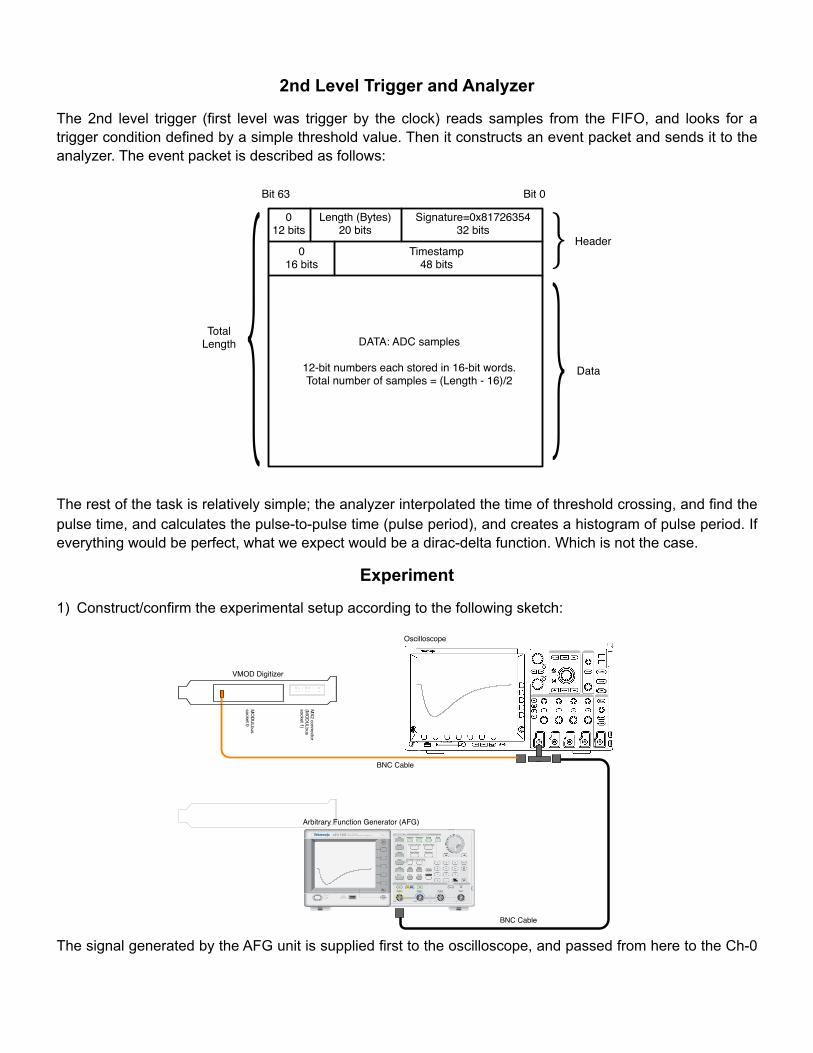
The 2nd level trigger (first level was trigger by the clock) reads samples from the FIFO, and looks for a trigger condition defined by a simple threshold value. Then it constructs an event packet and sends it to the analyzer. The event packet is described as follows:
Signature=0x8172635432 bits
Length (Bytes)20 bits
Timestamp48 bits
012 bits
016 bits
DATA: ADC samples
12-bit numbers each stored in 16-bit words.Total number of samples = (Length - 16)/2
Bit 0Bit 63
} Header
} Data{TotalLength
The rest of the task is relatively simple; the analyzer interpolated the time of threshold crossing, and find the pulse time, and calculates the pulse-to-pulse time (pulse period), and creates a histogram of pulse period. If everything would be perfect, what we expect would be a dirac-delta function. Which is not the case.
Experiment
1) Construct/confirm the experimental setup according to the following sketch:
!"#$%&
'!"()*+,)-!
./0.1#!!•!!$%&'())('*+%!2-$-3-
!,-./!0/1!
2!3(%4!56'+7
('*+%&&8&'-7-!59
!
!
!245-&6//*789/:-'"
-)9:/.1)-:;-!&'(%<(=<!>
?@ABC
$!*&!<-)*.-=-<!D*';!(%!$E5A&'8)-!F=(GH-'!(&!&;+D
%!*%!I*J6=-!K/!$'!;(&!(!&L6(=-!+M-%*%J!I+=!';-!I=+%'!&*<-!G+%%-G'+=&!+I!7
+<6)-!1/!C+%%-G'*+%&!'+!7
+<6)-!N!G(%!F-!7(<-!';=+6J;!';-!
>OP!G+%%-G'+=/!
!!Q=(GH-'&!I+=!&M-G*()!(MM)*G('*+%&!-R*&'!+=!G(%!F-!<-.-)+M-<!+%!G6&'+7-=&!=-L6-&'/!5%!-R(7
M)-!I+=!&6G;!(!F=(GH-'!*&!6&-<!I+=!>
?@ABC
$!D*';!+%-!+=!'D
+!S>?@A$C5T!7+<6)-&!(&!&;+D
%!*%!I*J6=-!0/!:;*&!F=(GH-'!;(&!+M-%*%J&!&M-G*()!'+!';-!UM*%!@
AEVQ!G+%%-G'+=&!I+=!C
5TF6&/!:;-!G+%%-G'*+%!'+!';-!
C5TF6&!7
+<6)-!*%!&+GH-'!N!*&!7(<-!';=+6J;!(!&;+='!(<(M'-=!"C
+%%-G'+=!>OP!*&!=-7
+.-<!I=+7!';-!
>?@ABC
$!*%!&6G;!(!G(&-#/!!5&!(%+';-=!+M'*+%W!8+6!G(%!(''(G;!(!I)('!G(F)-!G+%%-G'*+%!'+!';-!@
AEVQ!I=+%'!M(%-)!G+%%-G'+=!+I!';-!
7+<6)-!*%!&+GH-'!NW!(%<!*%&'())!';-!+';-=!-%<!+%!(!I=--!F=(GH-'!+=!'+!&+7
-!+';-=!&6*'(F)-!7+6%'*%J!
M+&*'*+%!+I!';-!BC!;+6&*%J/!
!24;-<6=8>
.+*-&6/)9?*+.896/)-
X+=!(%8!*%I+=7('*+%!(F+6'!*%&'())*%J!<=*.-=&!(%<!+';-=!&+I'D
(=-!M(GH(J-&!=-)('-<!'+!';-!>?@ABC
$W!=-I-=!'+!';-!<+G67
-%'('*+%!';('!G+7-&!D
*';!';('!<=*.-=!+=!&+I'D(=-/!
!!!
C5T!1
E'('6&YZ@
&!+IC5T!1
C5T!N
!I*J6=-!0[!EM-G*()!F=(GH-'!I+=!S>?@A$C5T!7+<6)-&!
>?@VYF6&
&+GH-'!1
>OP!G+%%-G'+=
">?@VYF6&
&+GH-'!N#
!I*J6=-!K[!E'(%<(=<!F=(GH-'!
AFG3000 Series Arbitrary/Function Generators Reference Manual 1-1
Operating Basics
The AFG3000 Series Arbitrary/Function Generators front panel is divided into easy to use functional areas. This section provides you with a quick overview of the controls. Figure 1-1 shows the front panel of dual-channel model.
Figure 1-1: Dual-channel model
Output
USBMemory
USBMemory
AFG 3102 1GS/s100MHz
DUAL CHANNELARBITRARY/FUNCTION GENERATOR
InputOutput Output
Channel TriggerTrigger
View
Ch2Ch1
Run ModeFunctionSine
Leading/TrailingDuty/Width
Sweep Burst
Edit Utility
Save RecallMore...
Arb
Pulse
Ramp
Square
Continuous Modulation
Default
Help
Offset/Low
Frequency/Period Amplitude/High
Phase Delay
Arbitrary Function Generator (AFG)
!"#$%&&%$'("
!" )(*+, (-- .(/, (#0'&&(#0(1+2
#" !"#+,$ $3+ 456 !%#3 7,'8+ '"$( $3+ -,("$91%"+&456 1(,$ (" .(/, (#0'&&(#0(1+2
$" )(*+, (" $3+ (#0'&&(#0(1+2 :3+ '"#$,/;+"$%/$(;%$'0%&&. ,+0(<"'=+# $3+ ,+1&%0+;+"$",;*%,+ %"7 '"#$%&&# '$2!- $3+ '"#$,/;+"$ 7(+# "($ '"#$%&& $3+",;*%,+> ,+,/" $3+ 1,(0+7/,+2 !- $3+1,(?&+; 0("$'"/+#> $,. % 7'--+,+"$ ;(7+& (-456 !%#3 7,'8+2 @'"%&&.> '- "++7+7> 0("$%0$A/%&'"+7 #+,8'0+ 1+,#(""+&2
!"#$% !" #"$ %"&'( ")) $*' "+,-.."+,"%' "(('/"0' $*' 123 !4+* 5(-0' 6#$-. $*' "+,-.."+,"%'"#-+*'+ -#+$4..-#7 $*' "(/&4('8
BC D5EFCCC %"7 G)EFCCC 5+,'+# E#0'&&(#0(1+# 4#+, D%"/%&
Oscilloscope
BNC Cable
BNC Cable
VMOD Digitizer
The signal generated by the AFG unit is supplied first to the oscilloscope, and passed from here to the Ch-0

input of the digitizer card. Make sure that the impedance of the oscilloscope is adjusted to be 50 Ω, and use a T-BNC to pass the signal over the oscilloscope.
2) Login to the PC and reset the lab8 directories, so all the work/changes done by the previous group are removed and a fresh copy of the files are installed. Do this by the following command:
! tdaq@adc:~$ reset_lab8
“tdaq@adc:~$” is your prompt, “reset_lab8” is the command. This will create two directories in your home directory, called “vmod” and “afg.” vmod directory contains the ROC, analyzer and the device driver. afg contains a utility to configure the Arbitrary Function Generator. In addition to this, you will see an editor window containing the relevant source codes for this exercise.
3) Change AFG function (if needed) such that you get the following function through the Ch1 output of the AFG:
At
τe−t/τ+1
where A = -4 volts, τ = 120µsec . There is also a PULSE_FREQ definition in the function.c . The function that will be generated will be repeated with this frequency. Set PULSE_FREQ to be 400 Hz (2.5 msec period). Save function.c and give the following command:
! tdaq@adc:~$ ./setafg
This will setup the function generator. You can see a signal on the oscilloscope that will look like:
Arbitrary function generator is used to simulate a scintillator type pulse. It is extremely predictable and reproducible. We will use these pulses, and measure the time intervals from one pulse to the other.

4) The setup of the experiment is completed. Now, the aim is to measure the time intervals between these repetitive pulses as shown below:
T ≈ 2.5msec
We will measure these intervals tens of thousands times per second and create a histogram showing the distribution of T. The usage of the online analysis program is as follows:
Usages: ./analyze_gui [-h] Help/usage [-n buffer_size] Buffer size [-w width] Pulse: width [-p pre_width] Pulse: width before threshold] [-t threshold] Pulse: trigger threshold [-b bins] Histogram: Number of bins [-B bin_width] Histogram: Bin width [-l bin_low] Histogram: Lower limit [-r bin_high] Histogram: Upper limit [-T period] Histogram: Refresh rate
!This program will do the following:
a) Will configuration parameters to the digitizer (threshold/width/pre_width), and ARM it to start the acquisition.
b) A thread will read the events from the PCI card and put into a local buffer.
c) Another thread will read the events one by one, and it will find the crossing point of the threshold time by interpolating a given number of samples around the interested point.
d) After each time determination, its difference from the previous value is found and fed into a histogram you see on the screen.
e) It also shows the samples of the signal, just like an oscilloscope, on the screen every second. This is the raw data we get from the board. It is for diagnostic.
Start this program with: threshold=1250, bin_width=64, pre_width=8, bin_width=10e-9, low_limit=2.499e-3, high_limit=2.501e-3.
5) Turn off the AFG signal by pressing the “On” of Ch1 on the AFG, once you collect at least 10,000 events which is enough to determine the deviation of the distribution precisely. The histogram on the screen should look like:

Perform a gaussian fit on the tdiff histogram, and note the fit parameters below:
! Mean-period! ! =! ................
! Sigma-period!! =! ................
We expect to get about 2.5 msec for the mean value, which what we programmed into the AFG. The question is how stable is this value? Sigma (the width of the distribution) is the quantity of interest. If it is stable, then we should always get the same value for the period. If there is a jitter/error in the period, the time of the sampling is represented by t i ± σ t, where i is the sampling number. Note, however that
Ti = t i - t i-1, thus its error is σT =√
2σt . This is what we measured. Then, determine σ t, and note this
below: ! Sigma-sampling-time!=! ................