pct cooling towers...2 pct cooling tower 4 cti certification 6 benefits 8 pct construction details...
TRANSCRIPT

2 PCTCOOLINGTOWER
4 CTICERTIFICATION
6 BENEFITS
8 PCTCONSTRUCTIONDETAILS
PCT Cooling Towers
10 CUSTOMFEATURES&OPTIONS
16 ENGINEERINGDATA
24 STRUCTURALSUPPORT
28 PRODUCTLAYOUT
32 ENGINEERINGSPECIFICATIONS
T A B L E O F C O N T E N T S
B A C A U S T R A L I A

2 Q U E S T I O N S ? C A L L 1 3 0 0 . 1 3 4 . 6 2 2 O R V I S I T W W W . B A L T I M O R E A I R C O I L . C O M . A U
The PCT brings you the most respected counterflow, induced draft cooling tower in the industry. Being CTI certified and engineered with input from end users, the PCT’s design highlights BAC’s commitment to performance, ease of maintenance, low installation costs, reduced energy consumption and durable corrosion resistant construction. Offering a compact footprint for low to medium tonnage requirements, the PCT provides an efficient solution for installations with space constraints. With unparalleled access to the complete unit interior, the PCT makes routine inspection and maintenance easier than ever before.

M A R 1 0 2 - 4 3
BAC’sPCT:TheSuperiorCounterflowUnit
DesignedforSmalltoMediumRequirements210to1,507kWinaSingleCell
Upto344l/sforProcessApplications
EasytoMaintain
ReducedEnvironmental
Impact
ContinuousEngineeringRefinement
LowInstalled
Cost
CTICertifiedthermal
performance,Certification#10-11-13
Δ Δ Δ Δ Δ

4 Q U E S T I O N S ? C A L L 1 3 0 0 . 1 3 4 . 6 2 2 O R V I S I T W W W . B A L T I M O R E A I R C O I L . C O M . A U
CTICertification
›› CTICertificationThe Cooling Technology Institute (CTI) is an independent body established in 1950 that provides certification for cooling tower products. CTI certification is recognised in the industry as the benchmark for cooling tower performance evaluation. Worldwide there are over 70 cooling tower lines making available 6,500 CTI certified models.
›` To obtain CTI certification, the independent body tests a sample model of the product line and compares the results to published claims. Every year, a re-verification test is performed on another model within the product line to confirm that the as built product is faithful to original expectations.
›` CTI certification is the only way to ensure performance claims are accurate without a costly field performance test. CTI certification enables designers to reduce safety margins, while providing the peace of mind that the equipment will perform as specified.
›› PCTCertificationThe PCT Cooling Tower range is certified by the Cooling Technology Institute (CTI) in 2010 with validation number 10-11-13. The certification process is ongoing and BAC is committed to the continual expansion of the PCT range. While there is an extensive range of PCT models already available, work is being done to increase this by the inclusion of larger box sizes.
Performance Graph
M A R 1 0 2 - 4 5

6 Q U E S T I O N S ? C A L L 1 3 0 0 . 1 3 4 . 6 2 2 O R V I S I T W W W . B A L T I M O R E A I R C O I L . C O M . A U
PCTBenefits
›› LowEnvironmentalImpact
›` ENERGY EFFICIENT• Fan motors meet MEPS2 2006 efficiency requirements as per
AS1359.5.
• High efficiency low sound axial fans as standard.
›` SOUND REDUCTION OPTIONS• Standard low sound fan optimises sound and thermal performance.
• For further reduced sound levels, Super Low Sound Fans and splash water silencers are available.
›` AS3666 COMPLIANCE• Sloping cooling tower basin allows for free draining.
• Smooth internal surfaces to facilitate cleaning.
• Quick fill connection for easy and fast refilling after cleaning.
• Easily removable fill.
• High performance drift eliminators.
›› DurableConstruction›` Enhanced longevity with a variety of materials of construction (see
page 8 for details).
›` SUPERIOR PULTRUDED COMPOSITE CONSTRUCTION
The use of high strength Pultruded Composite components for the primary structure combined with BAC’s patented “Bonded Panel to Post Connection”, offers many advantages over conventional hand laid or chopped strand fibreglass construction methods. Pultruded composites possess a superior strength to weight ratio of up to five times that of chopped strand fibreglass.
›› ReliableYear-RoundOperation
›` DIRECT DRIVE POWER TRAIN FAN SYSTEM (MODELS PCT0505, PCT0606, PCT0707, PCT0710)• Maintenance free operation.
• IP66 rated Wet Air Stream cooling tower motors.
›` BELT DRIVE POWER TRAIN FAN SYSTEM (MODELS PCT0808, PCT0812, PCT0909, PCT0913, PCT1010, PCT1111)• Heavy duty SPB belts for extended belt life.
• Extended lubrication lines standard.
• Single tool belt adjustment.
Standard High Efficiency Low Sound Fan
Patented “Bonded Panel to Post Connection”
Pultruded Composite Strength
Belt Drive Power Train
M A R 1 0 2 - 2 7
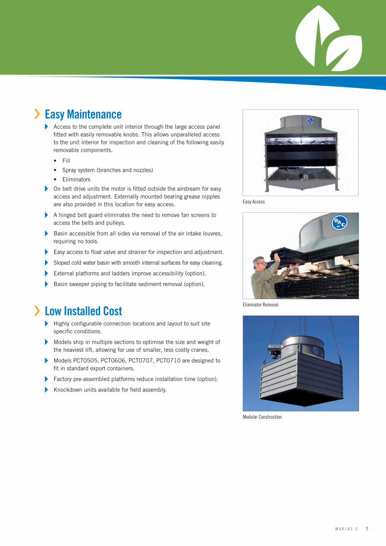
›› EasyMaintenance›` Access to the complete unit interior through the large access panel
fitted with easily removable knobs. This allows unparalleled access to the unit interior for inspection and cleaning of the following easily removable components.
• Fill
• Spray system (branches and nozzles)
• Eliminators
›` On belt drive units the motor is fitted outside the airstream for easy access and adjustment. Externally mounted bearing grease nipples are also provided in this location for easy access.
›` A hinged belt guard eliminates the need to remove fan screens to access the belts and pulleys.
›` Basin accessible from all sides via removal of the air intake louvres, requiring no tools.
›` Easy access to float valve and strainer for inspection and adjustment.
›` Sloped cold water basin with smooth internal surfaces for easy cleaning.
›` External platforms and ladders improve accessibility (option).
›` Basin sweeper piping to facilitate sediment removal (option).
›› LowInstalledCost›` Highly configurable connection locations and layout to suit site
specific conditions.
›` Models ship in multiple sections to optimise the size and weight of the heaviest lift, allowing for use of smaller, less costly cranes.
›` Models PCT0505, PCT0606, PCT0707, PCT0710 are designed to fit in standard export containers.
›` Factory pre-assembled platforms reduce installation time (option).
›` Knockdown units available for field assembly.
Easy Access
Eliminator Removal
Modular Construction
8 Q U E S T I O N S ? C A L L 1 3 0 0 . 1 3 4 . 6 2 2 O R V I S I T W W W . B A L T I M O R E A I R C O I L . C O M . A U
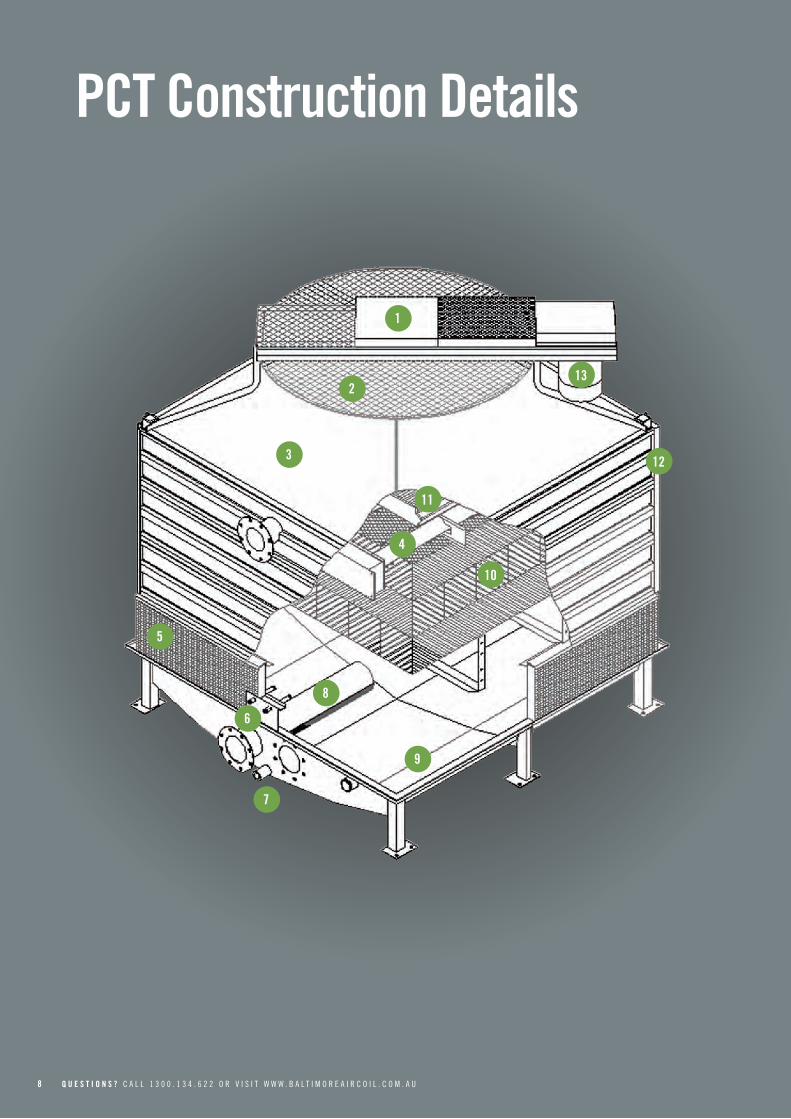
PCTConstructionDetails
1
2
3
4
6
7
8
9
10
11
12
13
5
M A R 1 0 2 - 3 9
Strainer ` Stainless steel construction, anti-vortex design.
ColdWaterBasin ` The cold water basin is made of fibreglass
reinforced polyester (FRP) with extra reinforcement in critical areas.
` Sloped basin sides with smooth internal finish for easy cleaning.
Fill ` The fill is impervious to rot, decay and resistant to
fungus or biological attacks.
` Fill consists of high efficiency crossfluted sheets, assembled into lightweight blocks.
` Blocks are sized for easy handling and removal for cleaning.
DriftEliminators ` UV resistant non-corrosive material, impervious to
rot, decay and biological attack.
` Three distinct changes in air direction to reduce drift loss significantly.
` Assembled in easy to handle sections, which can be removed for access to the equipment interior.
` AS3666 Compliant.
AccessDoor ` The larger access door is easily removable to provide
complete access to drift eliminators, spray system and fill.
` Larger units are equipped with anchor points to secure door when removed.
Motor ` Models PCT0505 to PCT0707 utilise direct drive IP66
cooling tower duty motor.
` Larger units have the fan motor outside of the moist discharge air stream and use high efficiency belt drives.
` Belts provide reliability and long service life with low maintenance requirements.
DriveTrain ` Easy access to drives and belts for inspection and
adjustment.
` Stainless steel shaft.
` Heavy-duty bearings.
` Heavy-duty SPB Belts
Fan ` Axial Fans.
` Small tip clearance tolerance.
` Low air inlet velocity.
` Minimum Noise.
Roofdeck ` Smooth faced air entry fan cylinders.
` Close manufacturing tolerances allow small tip clearance providing an increased fan efficiency.
WaterDistributionSystem ` Low pressure, stationary type nozzles.
` Heavy duty PVC spray branches are grommeted to facilitate removal and cleaning.
Louvres ` Removal of the louvres provides access to all sides
of the cold water basin for inspection, cleaning and maintenance.
Make-upAssembly ` Adjustable water make-up assembly, over flow and
quick fill connections are supplied standard.
Connections ` All connections 200NB and longer are Table E
Flange pattern.
` Connections 150NB and smaller are male threaded BSP.
1
2
3
4
6
7
8
9
10
11
12
13
5

10 Q U E S T I O N S ? C A L L 1 3 0 0 . 1 3 4 . 6 2 2 O R V I S I T W W W . B A L T I M O R E A I R C O I L . C O M . A U
PCTCustomFeatures&Options
›› MaterialsofConstructionDetermining the appropriate material of construction for a project depends on several factors, including water quality, climate and environmental conditions, availability of time and manpower for maintenance, unit lifetime requirements, and budget. BAC provides the widest variety of material of construction options in the industry and has the ability to provide a solution to meet all conditions and budgets.
›` STANDARD CONSTRUCTION
The PCT has been designed to be a highly corrosive resistant and durable cooling tower. The frame and casing panels are constructed of high strength pultruded composite fibreglass components joined together using BAC’s patented bonded panel to post connection. All wetted steel components and hardware are Type 304 Stainless Steel as standard. Mechanical equipment supports are constructed of ZAM, a Next Generation hot dip coated sheet providing superior corrosion protection to standard galvanised sheet. See Product Spotlight document #MAR0606 for more details on ZAM.
›` TYPE 316 STAINLESS STEEL WETTED PARTS (OPTION)
All wetted steel components in Type 316 Stainless Steel to provide a superior resistance to corrosion. Mechanical equipment supports are constructed of ZAM.
›` FULL TYPE 304 STAINLESS STEEL (OPTION)
All steel components including the mechanical equipment supports in Type 304 Stainless Steel.
›` FULL TYPE 316 STAINLESS STEEL (OPTION)
All steel components including the mechanical equipment supports in Type 316 Stainless Steel.
›` BASINLESS UNIT CONSTRUCTION (OPTION)
The basinless unit construction option enables PCT Cooling Towers to be directly installed on new or existing cold water basins. This custom feature simplifies piping and pumping requirements of multi-cell installations, reduces maintenance costs and provides a cost-effective solution for many field erected replacement projects. BAC is the only leading evaporative cooling equipment manufacturer to offer basinless construction for factory assembled equipment.
Example Installation
Example Installation
Basinless Unit Construction

M A R 1 0 2 - 4 11
›› DriveSystemOptionsThe fan drive system provides the cooling air necessary to reject unwanted heat from the system to the atmosphere. All BAC drive systems use MEPS2-2006 Compliant motors.
›` DIRECT DRIVE
Standard on Models PCT0505, PCT0606, PCT0707, PCT0710.Direct drive systems have the benefit of simplicity by having fewer moving parts, which reduces maintenance requirements and friction losses within the drive system. All PCT direct drive units use cooling tower duty motors which are specially designed for the harsh environment of a cooling tower and have permanently lubricated bearings, drastically decreasing the maintenance requirement of the motor.
›` BELT DRIVE POWER TRAIN
Standard on Models PCT0808, PCT0812, PCT0909, PCT0913, PCT1010, PCT1111. The belt drive power train utilises state-of-the-art technology to ensure ease of maintenance and reliable year-round performance. This BAC engineered drive system consists of SPB belts and two pulleys located at minimal shaft centreline distances to maximise belt life. The belt drive power train requires only periodic inspection of components and belt tensioning, which is simple with a single tool adjustment, and requires less downtime. All PCT belt drive units come standard with extended lubrication lines to the edge of the fan cylinder. BAC belt drive systems are the most durable and maintenance friendly belt drive systems on the market.
›` VIBRATION CUTOUT SWITCH (OPTION)
A factory mounted vibration cutout switch is available to effectively protect against rotating equipment failure. BAC provides a solid-state electronic vibration cutout switch in a NEMA 4 enclosure to ensure reliable protection. Additional contacts are provided to activate an alarm. Remote reset capability is also included.
›` CONTROLS
BAC can provide optional preprogrammed VSD’s using the design conditions provided with the evaporative cooling equipment and the fan motor data at time of manufacture. These factory settings provide the evaporative equipment operator or commissioning personnel the flexibility to start the equipment using the factory preprogrammed settings or customise any of the control parameters to suit the application or site specific conditions. The VSD is programmed in PID Control with Auto Start, Sleep Mode and a Set Point Reference. A Temperature Sensor is factory installed at the outlet of the evaporative cooling equipment which measures the leaving water temperature.
Direct Drive
Unit Controls
12 Q U E S T I O N S ? C A L L 1 3 0 0 . 1 3 4 . 6 2 2 O R V I S I T W W W . B A L T I M O R E A I R C O I L . C O M . A U
›› ColdWaterBasinThe cooling tower water collects in the cold water basin which provides the required head pressure for the cooling system pump. The standard PCT cold water basin is constructed of moulded FRP and utilises a sloped pan design to eliminate stagnant water zones, which are susceptible to biological growth.
›` SST COLD WATER BASIN
As an alternative to FRP, the PCT can be supplied with a Type 304 or 316 Stainless Steel cold water basin.
›` STANDARD MECHANICAL WATER LEVEL CONTROL
Mechanical make-up valves must operate continuously in the moist and turbulent environment existing within evaporative cooling equipment. Due to this environment, the operation of the valve must be simple, and the valve must be durable. BAC’s high quality mechanical water level control assembly is standard with all units, and has been specially designed to provide the most reliable operation while being easy to maintain. This accessory is omitted for remote sump applications.
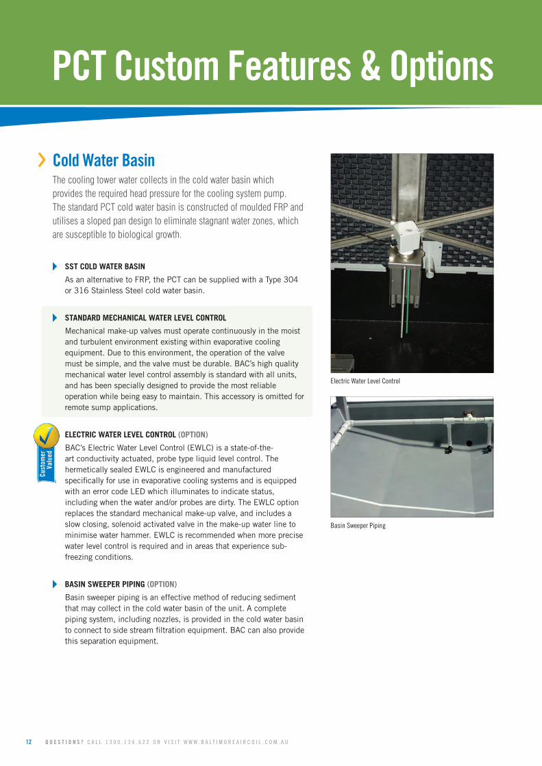
›` ELECTRIC WATER LEVEL CONTROL (OPTION)
BAC’s Electric Water Level Control (EWLC) is a state-of-the-art conductivity actuated, probe type liquid level control. The hermetically sealed EWLC is engineered and manufactured specifically for use in evaporative cooling systems and is equipped with an error code LED which illuminates to indicate status, including when the water and/or probes are dirty. The EWLC option replaces the standard mechanical make-up valve, and includes a slow closing, solenoid activated valve in the make-up water line to minimise water hammer. EWLC is recommended when more precise water level control is required and in areas that experience sub-freezing conditions.
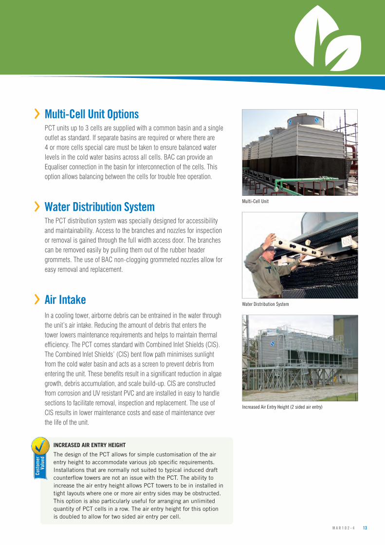
›` BASIN SWEEPER PIPING (OPTION)
Basin sweeper piping is an effective method of reducing sediment that may collect in the cold water basin of the unit. A complete piping system, including nozzles, is provided in the cold water basin to connect to side stream filtration equipment. BAC can also provide this separation equipment.
Basin Sweeper Piping
Electric Water Level Control
Cust
omer
Valu
ed
PCTCustomFeatures&Options
M A R 1 0 2 - 4 13
›› Multi-CellUnitOptionsPCT units up to 3 cells are supplied with a common basin and a single outlet as standard. If separate basins are required or where there are 4 or more cells special care must be taken to ensure balanced water levels in the cold water basins across all cells. BAC can provide an Equaliser connection in the basin for interconnection of the cells. This option allows balancing between the cells for trouble free operation.
›› WaterDistributionSystemThe PCT distribution system was specially designed for accessibility and maintainability. Access to the branches and nozzles for inspection or removal is gained through the full width access door. The branches can be removed easily by pulling them out of the rubber header grommets. The use of BAC non-clogging grommeted nozzles allow for easy removal and replacement.
›› AirIntakeIn a cooling tower, airborne debris can be entrained in the water through the unit’s air intake. Reducing the amount of debris that enters the tower lowers maintenance requirements and helps to maintain thermal efficiency. The PCT comes standard with Combined Inlet Shields (CIS). The Combined Inlet Shields’ (CIS) bent flow path minimises sunlight from the cold water basin and acts as a screen to prevent debris from entering the unit. These benefits result in a significant reduction in algae growth, debris accumulation, and scale build-up. CIS are constructed from corrosion and UV resistant PVC and are installed in easy to handle sections to facilitate removal, inspection and replacement. The use of CIS results in lower maintenance costs and ease of maintenance over the life of the unit.
›` INCREASED AIR ENTRY HEIGHT
The design of the PCT allows for simple customisation of the air entry height to accommodate various job specific requirements. Installations that are normally not suited to typical induced draft counterflow towers are not an issue with the PCT. The ability to increase the air entry height allows PCT towers to be in installed in tight layouts where one or more air entry sides may be obstructed. This option is also particularly useful for arranging an unlimited quantity of PCT cells in a row. The air entry height for this option is doubled to allow for two sided air entry per cell.
Multi-Cell Unit
Water Distribution System
Increased Air Entry Height (2 sided air entry)
Cust
omer
Valu
ed

14 Q U E S T I O N S ? C A L L 1 3 0 0 . 1 3 4 . 6 2 2 O R V I S I T W W W . B A L T I M O R E A I R C O I L . C O M . A U
Heat Transfer Surface
Factory Assembly
›› Fill
›` STANDARD HEAT TRANSFER SURFACE
The film type heat transfer surface supplied as standard with the PCT has been carefully selected for industrial applications. The spacing between the surface sheets gives excellent air/water contact with low air pressure loss. The standard heat transfer surface provides high thermal efficiency and is sufficient to avoid clogging in most operating environments.
›` ANTI FOULING FILL (OPTION)
For particularly dirty water applications, anti fouling fill packs or splash fill can be provided depending on the specific application.
›› ShippingandRiggingBAC units are factory-assembled to ensure uniform quality with minimum field assembly. Each unit has been designed with rigging and assembly in mind and includes features to minimise the number of tools required and installation time.
›` CASING/PAN JOINT SYSTEM
The on-site connection between casing and basin in PCT units is made simple by the tapered joining spigots fitted to each basin leg. These spigots guide the casing onto the basin and two bolts are used per leg complete the connection. This specially designed joint speeds up on site installation.
›` KNOCKDOWN UNITS (OPTION)
Knockdown units are available for jobs where access to the cooling tower location is limited by elevators, doorways, or similar obstacles, where lifting methods impose very strict weight limits, or where the shipping cost of a fully assembled tower is excessive. All materials of construction and design features are the same as those of a factory assembled unit. BAC technical advisors are available for assembly supervision.
›` CONTAINERISED UNITS (OPTION)
The PCT0505, PCT0606, PCT0707 and PCT0710 can be containerised in a standard shipping container for easy export, allowing for the lowest transportation cost possible when providing high quality BAC units to all parts of the world.
PCTCustomFeatures&Options

M A R 1 0 2 - 4 15
Water Silencers
›› SoundOptionsRecognition of the importance of sound restriction is growing and can be a very important design criterion for many projects. BAC maintains the widest selection of sound mitigating options in the market place and can provide the most cost effective option to meet any requirement.
›` STANDARD LOW SOUND FAN
The fan provided for all PCT Cooling Towers is selected to optimise sound levels and maximise thermal performance.
›` SUPER LOW SOUND FAN (OPTION)
The Super Low Sound Fan option reduces sound up to 8 dBA. Adding a high solidity fan allows for decreased fan speed, which proportionally decreases sound levels.
›` WATER SILENCERS (OPTION)
Water silencers are available to reduce the sound of falling water inherent in induced draft counterflow cooling towers. Use of water silencers can reduce the sound contribution due to water noise to negligible levels.
›› AccessOptionsFor the purposes of access to the drive system for inspection or maintenance, ladders and platforms can be provided. These can either take the form of factory assembled pods for inspection, or customised ladders and platforms designed to meet site specific conditions. All ladders and platforms are designed in accordance with AS1657. Ladders can be supplied at any length within the constraints of the standard.
›` MODULAR EXTERNAL PLATFORMS AND LADDER PACKAGES (OPTION)
Every modular external platform is preassembled and pre-fitted at the factory to ensure that every component will fit and function exactly as described. Most platforms are shipped fitted to the unit. In some cases it may be shipped loose where it can be easily rigged in the field using a minimum of additional fastners.
Customised Access
16 Q U E S T I O N S ? C A L L 1 3 0 0 . 1 3 4 . 6 2 2 O R V I S I T W W W . B A L T I M O R E A I R C O I L . C O M . A U
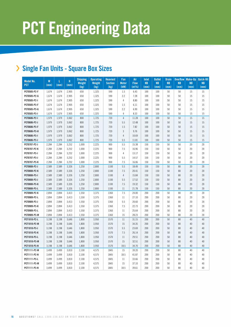
›› SingleFanUnits-SquareBoxSizes
PCTEngineeringData
ModelNo.PCT
W(mm)
L(mm)
H(mm)
ShippingWeight
(kg)
OperatingWeight
(kg)
HeaviestSection
(kg)
FanMotor(kW)
AirFlow
(m3/s)
InletNB
(mm)
OutletNB
(mm)
DrainNB
(mm)
OverflowNB
(mm)
Make-UpNB
(mm)
Quick-fillNB
(mm)
PCT0505-P2-F 1,674 1,674 2,905 650 1,325 590 1.5 6.43 100 100 50 50 15 15
PCT0505-P2-G 1,674 1,674 2,905 650 1,325 590 2.2 7.28 100 100 50 50 15 15
PCT0505-P2-I 1,674 1,674 2,905 650 1,325 590 4 8.80 100 100 50 50 15 15
PCT0505-P3-F 1,674 1,674 2,905 650 1,325 590 1.5 6.11 100 100 50 50 15 15
PCT0505-P3-G 1,674 1,674 2,905 650 1,325 590 2.2 6.90 100 100 50 50 15 15
PCT0505-P3-I 1,674 1,674 2,905 650 1,325 590 4 8.33 100 100 50 50 15 15
PCT0606-P2-I 1,979 1,979 3,062 800 1,725 720 4 11.28 100 100 50 50 15 15
PCT0606-P2-J 1,979 1,979 3,062 800 1,725 720 5.5 12.48 100 100 50 50 15 15
PCT0606-P3-F 1,979 1,979 3,062 800 1,725 720 1.5 7.82 100 100 50 50 15 15
PCT0606-P3-H 1,979 1,979 3,062 800 1,725 720 3 9.76 100 100 50 50 15 15
PCT0606-P3-I 1,979 1,979 3,062 800 1,725 720 4 10.69 100 100 50 50 15 15
PCT0606-P3-J 1,979 1,979 3,062 800 1,725 720 5.5 11.81 100 100 50 50 15 15
PCT0707-P2-J 2,284 2,284 3,252 1,000 2,225 900 5.5 15.38 150 150 50 50 20 20
PCT0707-P2-K 2,284 2,284 3,252 1,000 2,225 900 7.5 16.96 150 150 50 50 20 20
PCT0707-P3-I 2,284 2,284 3,252 1,000 2,225 900 4 13.17 150 150 50 50 20 20
PCT0707-P3-J 2,284 2,284 3,252 1,000 2,225 900 5.5 14.57 150 150 50 50 20 20
PCT0707-P3-K 2,284 2,284 3,252 1,000 2,225 900 7.5 16.06 150 150 50 50 20 20
PCT0808-P2-J 2,589 2,589 3,326 1,250 2,800 1100 5.5 18.49 150 150 50 80 20 20
PCT0808-P2-K 2,589 2,589 3,326 1,250 2,800 1100 7.5 20.41 150 150 50 80 20 20
PCT0808-P3-I 2,589 2,589 3,326 1,250 2,800 1100 4 15.84 150 150 50 80 20 20
PCT0808-P3-J 2,589 2,589 3,326 1,250 2,800 1100 5.5 17.52 150 150 50 80 20 20
PCT0808-P3-K 2,589 2,589 3,326 1,250 2,800 1100 7.5 19.32 150 150 50 80 20 20
PCT0808-P3-L 2,589 2,589 3,326 1,250 2,800 1100 11 21.78 150 150 50 80 20 20
PCT0909-P2-K 2,894 2,894 3,413 1,550 3,375 1360 7.5 24.00 200 200 50 80 20 20
PCT0909-P2-L 2,894 2,894 3,413 1,550 3,375 1360 11 27.10 200 200 50 80 20 20
PCT0909-P3-J 2,894 2,894 3,413 1,550 3,375 1360 5.5 20.60 200 200 50 80 20 20
PCT0909-P3-K 2,894 2,894 3,413 1,550 3,375 1360 7.5 22.73 200 200 50 80 20 20
PCT0909-P3-L 2,894 2,894 3,413 1,550 3,375 1360 11 25.64 200 200 50 80 20 20
PCT0909-P3-M 2,894 2,894 3,413 1,550 3,375 1360 15 28.23 200 200 50 80 20 20
PCT1010-P2-L 3,198 3,198 3,646 1,800 3,950 1570 11 31.15 200 200 50 80 40 40
PCT1010-P2-M 3,198 3,198 3,646 1,800 3,950 1570 15 34.35 200 200 50 80 40 40
PCT1010-P3-J 3,198 3,198 3,646 1,800 3,950 1570 5.5 23.69 200 200 50 80 40 40
PCT1010-P3-K 3,198 3,198 3,646 1,800 3,950 1570 7.5 26.14 200 200 50 80 40 40
PCT1010-P3-L 3,198 3,198 3,646 1,800 3,950 1570 11 29.51 200 200 50 80 40 40
PCT1010-P3-M 3,198 3,198 3,646 1,800 3,950 1570 15 32.51 200 200 50 80 40 40
PCT1010-P3-N 3,198 3,198 3,646 1,800 3,950 1570 18.5 34.70 200 200 50 80 40 40
PCT1111-P2-M 3,499 3,499 3,810 2,100 4,575 1845 15 39.20 200 200 50 80 40 40
PCT1111-P2-N 3,499 3,499 3,810 2,100 4,575 1845 18.5 41.87 200 200 50 80 40 40
PCT1111-P3-L 3,499 3,499 3,810 2,100 4,575 1845 11 33.66 200 200 50 80 40 40
PCT1111-P3-M 3,499 3,499 3,810 2,100 4,575 1845 15 37.10 200 200 50 80 40 40
PCT1111-P3-N 3,499 3,499 3,810 2,100 4,575 1845 18.5 39.61 200 200 50 80 40 40
M A R 1 0 2 - 4 17
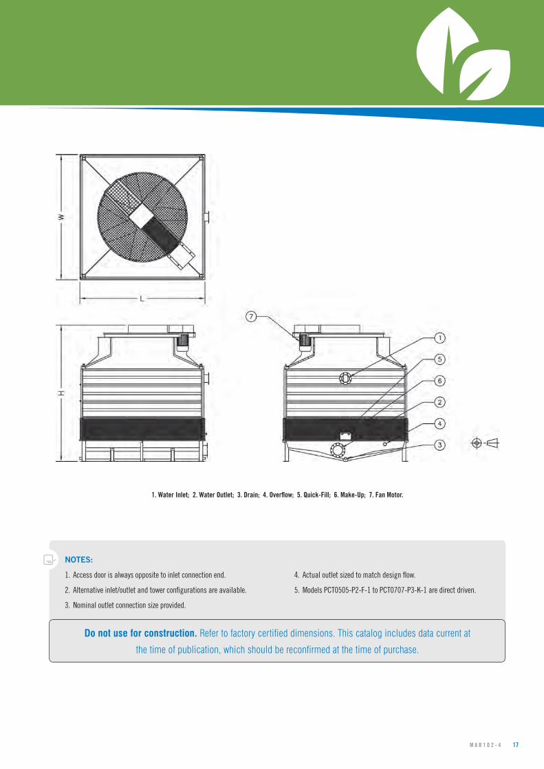
NOTES:
1. Access door is always opposite to inlet connection end.
2. Alternative inlet/outlet and tower configurations are available.
3. Nominal outlet connection size provided.
4. Actual outlet sized to match design flow.
5. Models PCT0505-P2-F-1 to PCT0707-P3-K-1 are direct driven.
1.WaterInlet;2.WaterOutlet;3.Drain;4.Overflow;5.Quick-Fill;6.Make-Up;7.FanMotor.
Do not use for construction. Refer to factory certified dimensions. This catalog includes data current at
the time of publication, which should be reconfirmed at the time of purchase.

18 Q U E S T I O N S ? C A L L 1 3 0 0 . 1 3 4 . 6 2 2 O R V I S I T W W W . B A L T I M O R E A I R C O I L . C O M . A U
PCTEngineeringData
›› SingleFanUnits-RectangularBoxSizes
ModelNo.PCT
W(mm)
L(mm)
H(mm)
ShippingWeight
(kg)
OperatingWeight
(kg)
HeaviestSection
(kg)
FanMotor(kW)
AirFlow
(m3/s)
InletNB
(mm)
OutletNB
(mm)
DrainNB
(mm)
OverflowNB
(mm)
Make-UpNB
(mm)
Quick-fillNB
(mm)
PCT0710-P2-K 2284 3420 3960 1500 3340 1350 7.5 20.94 150 150 50 80 40 40
PCT0710-P2-L 2284 3420 3960 1500 3340 1350 11 23.67 150 150 50 80 40 40
PCT0710-P3-J 2284 3420 3960 1500 3340 1350 5.5 17.98 150 150 50 80 40 40
PCT0710-P3-K 2284 3420 3960 1500 3340 1350 7.5 19.86 150 150 50 80 40 40
PCT0710-P3-L 2284 3420 3960 1500 3340 1350 11 22.43 150 150 50 80 40 40
PCT0812-P2-K 2589 3876 3984 1875 4200 1700 7.5 25.22 150 150 50 80 40 40
PCT0812-P2-L 2589 3876 3984 1875 4200 1700 11 28.52 150 150 50 80 40 40
PCT0812-P3-K 2589 3876 3984 1875 4200 1700 7.5 23.91 150 150 50 80 40 40
PCT0812-P3-L 2589 3876 3984 1875 4200 1700 11 27.02 150 150 50 80 40 40
PCT0812-P3-M 2589 3876 3984 1875 4200 1700 15 29.80 150 150 50 80 40 40
PCT0913-P2-L 2894 4335 4270 2400 5100 2100 11 33.56 200 200 50 80 40 40
PCT0913-P2-M 2894 4335 4270 2400 5100 2100 15 37.06 200 200 50 80 40 40
PCT0913-P3-L 2894 4335 4270 2400 5100 2100 11 31.80 200 200 50 80 40 40
PCT0913-P3-M 2894 4335 4270 2400 5100 2100 15 35.09 200 200 50 80 40 40
PCT0913-P3-N 2894 4335 4270 2400 5100 2100 18.5 37.49 200 200 50 80 40 40
PCT1015-P2-N 3198 4785 4580 3402 6927 2916 18.5 40.87 250 200 50 80 40 40
PCT1015-P2-O 3198 4785 4580 3402 6927 2916 22 43.11 250 200 50 80 40 40
PCT1015-P3-M 3198 4785 4580 3402 6927 2916 15 43.93 250 200 50 80 40 40
PCT1015-P3-N 3198 4785 4580 3402 6927 2916 18.5 46.90 250 200 50 80 40 40
PCT1015-P3-O 3198 4785 4580 3402 6927 2916 22 49.48 250 200 50 80 40 40
PCT1015-P3-P 3198 4785 4580 3402 6927 2916 30 54.40 250 200 50 80 40 40
PCT1116-P2-N 3499 5246 4763 3645 8264 3402 18.5 45.81 250 250 50 80 40 40
PCT1116-P2-0 3499 5246 4763 3645 8264 3402 22 48.37 250 250 50 80 40 40
PCT1116-P3-M 3499 5246 4763 3645 8264 3402 15 49.21 250 250 50 80 40 40
PCT1116-P3-N 3499 5246 4763 3645 8264 3402 18.5 52.57 250 250 50 80 40 40
PCT1116-P3-O 3499 5246 4763 3645 8264 3402 22 55.51 250 250 50 80 40 40
PCT1116-P3-P 3499 5246 4763 3645 8264 3402 30 61.13 250 250 50 80 40 40

M A R 1 0 2 - 4 19
NOTES:
1. Access door is always opposite to inlet connection end.
2. Alternative inlet/outlet and tower configurations are available.
3. Nominal outlet connection size provided.
4. Actual outlet sized to match design flow.
5. Models PCT0710-P2-K to PCT0710-P3-L are direct driven.
Do not use for construction. Refer to factory certified dimensions. This catalog includes data current at
the time of publication, which should be reconfirmed at the time of purchase.
1.WaterInlet;2.WaterOutlet;3.Drain;4.Overflow;5.Quick-Fill;6.Make-Up;7.FanMotor.
20 Q U E S T I O N S ? C A L L 1 3 0 0 . 1 3 4 . 6 2 2 O R V I S I T W W W . B A L T I M O R E A I R C O I L . C O M . A U
PCTEngineeringData
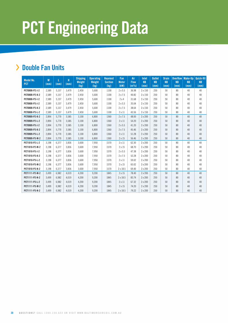
›› DoubleFanUnits
ModelNo.PCT
W(mm)
L(mm)
H(mm)
ShippingWeight
(kg)
OperatingWeight
(kg)
HeaviestSection
(kg)
FanMotor(kW)
AirFlow
(m3/s)
InletNB
(mm)
OutletNB
(mm)
DrainNB
(mm)
OverflowNB
(mm)
Make-UpNB
(mm)
Quick-fillNB
(mm)
PCT0808-P2-J-2 2,589 5,157 3,479 2,450 5,600 1100 2 x 5.5 36.98 2 x 150 250 50 80 40 40
PCT0808-P2-K-2 2,589 5,157 3,479 2,450 5,600 1100 2 x 7.5 40.82 2 x 150 250 50 80 40 40
PCT0808-P3-I-2 2,589 5,157 3,479 2,450 5,600 1100 2 x 4 31.68 2 x 150 250 50 80 40 40
PCT0808-P3-J-2 2,589 5,157 3,479 2,450 5,600 1100 2 x 5.5 35.04 2 x 150 250 50 80 40 40
PCT0808-P3-K-2 2,589 5,157 3,479 2,450 5,600 1100 2 x 7.5 38.64 2 x 150 250 50 80 40 40
PCT0808-P3-L-2 2,589 5,157 3,479 2,450 5,600 1100 2 x 11 43.56 2 x 150 250 50 80 40 40
PCT0909-P2-K-2 2,894 5,770 3,585 3,100 6,800 1360 2 x 7.5 48.00 2 x 200 250 50 80 40 40
PCT0909-P2-L-2 2,894 5,770 3,585 3,100 6,800 1360 2 x 11 54.20 2 x 200 250 50 80 40 40
PCT0909-P3-J-2 2,894 5,770 3,585 3,100 6,800 1360 2 x 5.5 41.20 2 x 200 250 50 80 40 40
PCT0909-P3-K-2 2,894 5,770 3,585 3,100 6,800 1360 2 x 7.5 45.46 2 x 200 250 50 80 40 40
PCT0909-P3-L-2 2,894 5,770 3,585 3,100 6,800 1360 2 x 11 51.28 2 x 200 250 50 80 40 40
PCT0909-P3-M-2 2,894 5,770 3,585 3,100 6,800 1360 2 x 15 56.46 2 x 200 250 50 80 40 40
PCT1010-P2-L-2 3,198 6,377 3,836 3,600 7,950 1570 2 x 11 62.30 2 x 200 250 50 80 40 40
PCT1010-P2-M-2 3,198 6,377 3,836 3,600 7,950 1570 2 x 15 68.70 2 x 200 250 50 80 40 40
PCT1010-P3-J-2 3,198 6,377 3,836 3,600 7,950 1570 2 x 5.5 47.38 2 x 200 250 50 80 40 40
PCT1010-P3-K-2 3,198 6,377 3,836 3,600 7,950 1570 2 x 7.5 52.28 2 x 200 250 50 80 40 40
PCT1010-P3-L-2 3,198 6,377 3,836 3,600 7,950 1570 2 x 11 59.02 2 x 200 250 50 80 40 40
PCT1010-P3-M-2 3,198 6,377 3,836 3,600 7,950 1570 2 x 15 65.02 2 x 200 250 50 80 40 40
PCT1010-P3-N-2 3,198 6,377 3,836 3,600 7,950 1570 2 x 18.5 69.40 2 x 200 250 50 80 40 40
PCT1111-P2-M-2 3,499 6,982 4,019 4,200 9,200 1845 2 x 15 78.40 2 x 200 250 50 80 40 40
PCT1111-P2-N-2 3,499 6,982 4,019 4,200 9,200 1845 2 x 18.5 83.74 2 x 200 250 50 80 40 40
PCT1111-P3-L-2 3,499 6,982 4,019 4,200 9,200 1845 2 x 11 67.32 2 x 200 250 50 80 40 40
PCT1111-P3-M-2 3,499 6,982 4,019 4,200 9,200 1845 2 x 15 74.20 2 x 200 250 50 80 40 40
PCT1111-P3-N-2 3,499 6,982 4,019 4,200 9,200 1845 2 x 18.5 79.22 2 x 200 250 50 80 40 40

M A R 1 0 2 - 4 21
NOTES:
1. Access door is always opposite to inlet connection end.
2. Alternative inlet/outlet and tower configurations are available.
3. Nominal outlet connection size provided.
4. Actual outlet sized to match design flow.
1.WaterInlet;2.WaterOutlet;3.Drain;4.Overflow;5.Quick-Fill;6.Make-Up;7.FanMotor.
Do not use for construction. Refer to factory certified dimensions. This catalog includes data current at
the time of publication, which should be reconfirmed at the time of purchase.
22 Q U E S T I O N S ? C A L L 1 3 0 0 . 1 3 4 . 6 2 2 O R V I S I T W W W . B A L T I M O R E A I R C O I L . C O M . A U
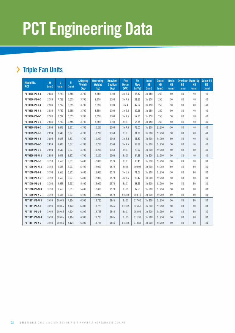
PCTEngineeringData
›› TripleFanUnits
ModelNo.PCT
W(mm)
L(mm)
H(mm)
ShippingWeight
(kg)
OperatingWeight
(kg)
HeaviestSection
(kg)
FanMotor(kW)
AirFlow
(m3/s)
InletNB
(mm)
OutletNB
(mm)
DrainNB
(mm)
OverflowNB
(mm)
Make-UpNB
(mm)
Quick-fillNB
(mm)
PCT0808-P2-J-3 2,589 7,732 3,555 3,700 8,350 1100 3 x 5.5 55.47 3 x 150 250 50 80 40 40
PCT0808-P2-K-3 2,589 7,732 3,555 3,700 8,350 1100 3 x 7.5 61.23 3 x 150 250 50 80 40 40
PCT0808-P3-I-3 2,589 7,732 3,555 3,700 8,350 1100 3 x 4 47.52 3 x 150 250 50 80 40 40
PCT0808-P3-J-3 2,589 7,732 3,555 3,700 8,350 1100 3 x 5.5 52.56 3 x 150 250 50 80 40 40
PCT0808-P3-K-3 2,589 7,732 3,555 3,700 8,350 1100 3 x 7.5 57.96 3 x 150 250 50 80 40 40
PCT0808-P3-L-3 2,589 7,732 3,555 3,700 8,350 1100 3 x 11 65.34 3 x 150 250 50 80 40 40
PCT0909-P2-K-3 2,894 8,646 3,671 4,700 10,200 1360 3 x 7.5 72.00 3 x 200 2 x 250 50 80 40 40
PCT0909-P2-L-3 2,894 8,646 3,671 4,700 10,200 1360 3 x 11 81.30 3 x 200 2 x 250 50 80 40 40
PCT0909-P3-J-3 2,894 8,646 3,671 4,700 10,200 1360 3 x 5.5 61.80 3 x 200 2 x 250 50 80 40 40
PCT0909-P3-K-3 2,894 8,646 3,671 4,700 10,200 1360 3 x 7.5 68.19 3 x 200 2 x 250 50 80 40 40
PCT0909-P3-L-3 2,894 8,646 3,671 4,700 10,200 1360 3 x 11 76.92 3 x 200 2 x 250 50 80 40 40
PCT0909-P3-M-3 2,894 8,646 3,671 4,700 10,200 1360 3 x 15 84.69 3 x 200 2 x 250 50 80 40 40
PCT1010-P2-L-3 3,198 9,556 3,931 5,400 12,000 1570 3 x 11 93.45 3 x 200 2 x 250 50 80 80 80
PCT1010-P2-M-3 3,198 9,556 3,931 5,400 12,000 1570 3 x 15 103.05 3 x 200 2 x 250 50 80 80 80
PCT1010-P3-J-3 3,198 9,556 3,931 5,400 12,000 1570 3 x 5.5 71.07 3 x 200 2 x 250 50 80 80 80
PCT1010-P3-K-3 3,198 9,556 3,931 5,400 12,000 1570 3 x 7.5 78.42 3 x 200 2 x 250 50 80 80 80
PCT1010-P3-L-3 3,198 9,556 3,931 5,400 12,000 1570 3 x 11 88.53 3 x 200 2 x 250 50 80 80 80
PCT1010-P3-M-3 3,198 9,556 3,931 5,400 12,000 1570 3 x 15 97.53 3 x 200 2 x 250 50 80 80 80
PCT1010-P3-N-3 3,198 9,556 3,931 5,400 12,000 1570 3 x 18.5 104.10 3 x 200 2 x 250 50 80 80 80
PCT1111-P2-M-3 3,499 10,465 4,124 6,300 13,725 1845 3 x 15 117.60 3 x 200 2 x 250 50 80 80 80
PCT1111-P2-N-3 3,499 10,465 4,124 6,300 13,725 1845 3 x 18.5 125.61 3 x 200 2 x 250 50 80 80 80
PCT1111-P3-L-3 3,499 10,465 4,124 6,300 13,725 1845 3 x 11 100.98 3 x 200 2 x 250 50 80 80 80
PCT1111-P3-M-3 3,499 10,465 4,124 6,300 13,725 1845 3 x 15 111.30 3 x 200 2 x 250 50 80 80 80
PCT1111-P3-N-3 3,499 10,465 4,124 6,300 13,725 1845 3 x 18.5 118.83 3 x 200 2 x 250 50 80 80 80

M A R 1 0 2 - 4 23
NOTES:
1. Access door is always opposite to inlet connection end.
2. Alternative inlet/outlet and tower configurations are available.
3. Nominal outlet connection size provided.
4. Actual outlet sized to match design flow.
1.WaterInlet;2.WaterOutlet;3.Drain;4.Overflow;5.Quick-Fill;6.Make-Up;7.FanMotor.
Do not use for construction. Refer to factory certified dimensions. This catalog includes data current at
the time of publication, which should be reconfirmed at the time of purchase.
24 Q U E S T I O N S ? C A L L 1 3 0 0 . 1 3 4 . 6 2 2 O R V I S I T W W W . B A L T I M O R E A I R C O I L . C O M . A U
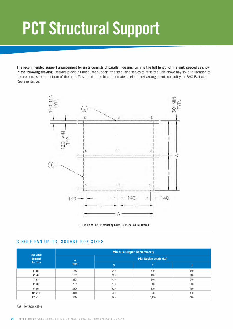
PCTStructuralSupport
The recommended support arrangement for units consists of parallel I-beams running the full length of the unit, spaced as shown in the following drawing. Besides providing adequate support, the steel also serves to raise the unit above any solid foundation to ensure access to the bottom of the unit. To support units in an alternate steel support arrangement, consult your BAC Balticare Representative.
S I N G L E F A N U N I T S : S Q U A R E B O X S I Z E S
PCT-2000NominalBoxSize
Minimum Support Requirements
A(mm)
Pier Design Loads (kg)
S T U
5’x5’ 1588 240 310 160
6’x6’ 1892 320 420 210
7’x7’ 2198 410 540 270
8’x8’ 2502 510 680 340
9’x9’ 2806 620 830 420
10’x10’ 3112 730 970 490
11’x11’ 3416 860 1,140 570
N/A = Not Applicable
1.OutlineofUnit;2.Mountingholes;3.PiersCanBeOffered.
M A R 1 0 2 - 4 25
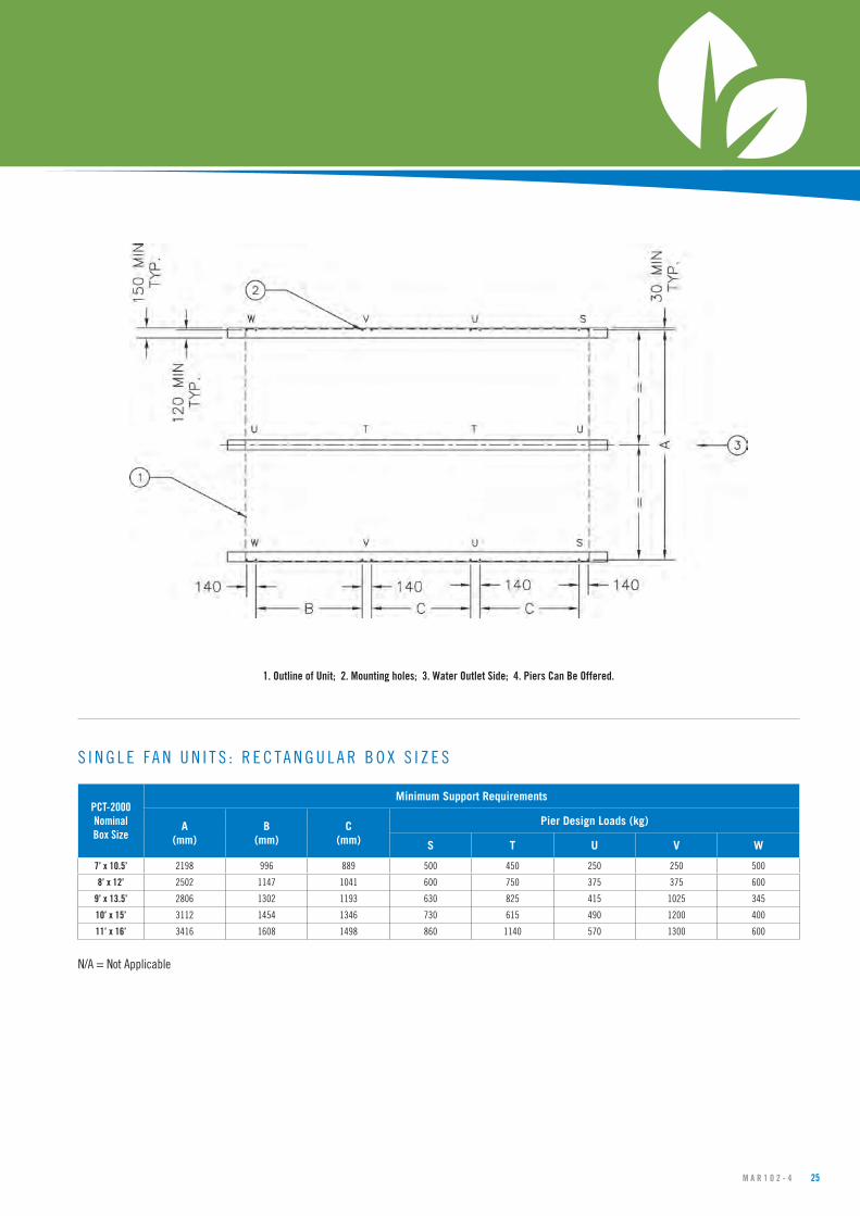
S I N G L E F A N U N I T S : R E C T A N G U L A R B O X S I Z E S
PCT-2000NominalBoxSize
Minimum Support Requirements
A(mm)
B(mm)
C(mm)
Pier Design Loads (kg)
S T U V W
7’x10.5’ 2198 996 889 500 450 250 250 500
8’x12’ 2502 1147 1041 600 750 375 375 600
9’x13.5’ 2806 1302 1193 630 825 415 1025 345
10’x15’ 3112 1454 1346 730 615 490 1200 400
11’x16’ 3416 1608 1498 860 1140 570 1300 600
N/A = Not Applicable
1.OutlineofUnit;2.Mountingholes;3.WaterOutletSide;4.PiersCanBeOffered.

26 Q U E S T I O N S ? C A L L 1 3 0 0 . 1 3 4 . 6 2 2 O R V I S I T W W W . B A L T I M O R E A I R C O I L . C O M . A U
PCTStructuralSupport
D O U B L E F A N U N I T S
PCT-2000NominalBoxSize
Minimum Support Requirements
A(mm)
Pier Design Loads (kg)
S T U
10’x5’ 1588 240 310 160
12’x6’ 1892 320 420 210
14’x7’ 2198 410 540 270
16’x8’ 2502 510 680 340
18’x9’ 2806 620 830 420
20’x10’ 3112 730 970 490
22’x11’ 3416 860 1,140 570
N/A = Not Applicable
1.OutlineofUnit;2.Mountingholes;3.PiersCanBeOffered.

M A R 1 0 2 - 4 27
T R I P L E F A N U N I T S
PCT-2000NominalBoxSize
Minimum Support Requirements
A(mm)
Pier Design Loads (kg)
S T U
15’x5’ 1588 240 310 160
18’x6’ 1892 320 420 210
21’x7’ 2,260 410 540 270
24’x8’ 2,560 510 680 340
27’x9’ 2,865 620 830 420
30’x10’ 3,170 730 970 490
33’x11’ 3,475 860 1,140 570
N/A = Not Applicable
1.OutlineofUnit;2.Mountingholes;3.PiersCanBeOffered.
Do not use for construction. Refer to factory certified dimensions. This catalog includes data current at
the time of publication, which should be reconfirmed at the time of purchase.
28 Q U E S T I O N S ? C A L L 1 3 0 0 . 1 3 4 . 6 2 2 O R V I S I T W W W . B A L T I M O R E A I R C O I L . C O M . A U
PCTProductLayout
Cooling towers depend upon an adequate supply of fresh, ambient air to provide design capacity. Other important considerations such as the proximity to building air intakes or discharges also must be taken into account when selecting and designing the equipment site. This bulletin presents the design guidelines for siting counter flow products in several situations typically encountered by designers. All of the guidelines present recommended spacing requirements for good performance, but more liberal spacing should be provided where possible.
Also, note that as the size of an installation grows larger and larger, the total amount of heat being rejected to the atmosphere and the volume of discharge air increases accordingly -- to the point where the towers virtually create their own environment. As a result, it becomes increasingly difficult to apply a set of correct general guidelines for every case. Consequently, it is recommended the layout of large counter flow product installations be referred to your local BAC Representative for review.
As is typical of axial fan equipment, counter flow products are not generally suited for indoor or ducted applications. In such situations, centrifugal fan units are preferred.
General Considerations:
When selecting the site for a counter flow product installation, consider the following factors;
1. Locate the unit to prevent the warm discharge air and any associated drift from being introduced into the fresh air intakes of the building(s) served by the unit or the intakes of neighbouring buildings.
2. Consider the potential for plume formation and its effect on the surroundings, such as large windowed areas, and pedestrian or vehicular traffic arteries.
3. Provide sufficient unobstructed space around the unit(s) to ensure an adequate supply of fresh, ambient air to the intake. Avoid situations where adjacent walls or structures might deflect some of the discharge airstream back into the air inlet (recirculation) or promote recirculation by generating high, downward air velocities in the vicinity of the intake. Also, avoid locations where building air intakes or exhausts, such as boiler stacks in the vicinity of the unit, might raise the inlet wet bulb temperature or starve the unit of air.
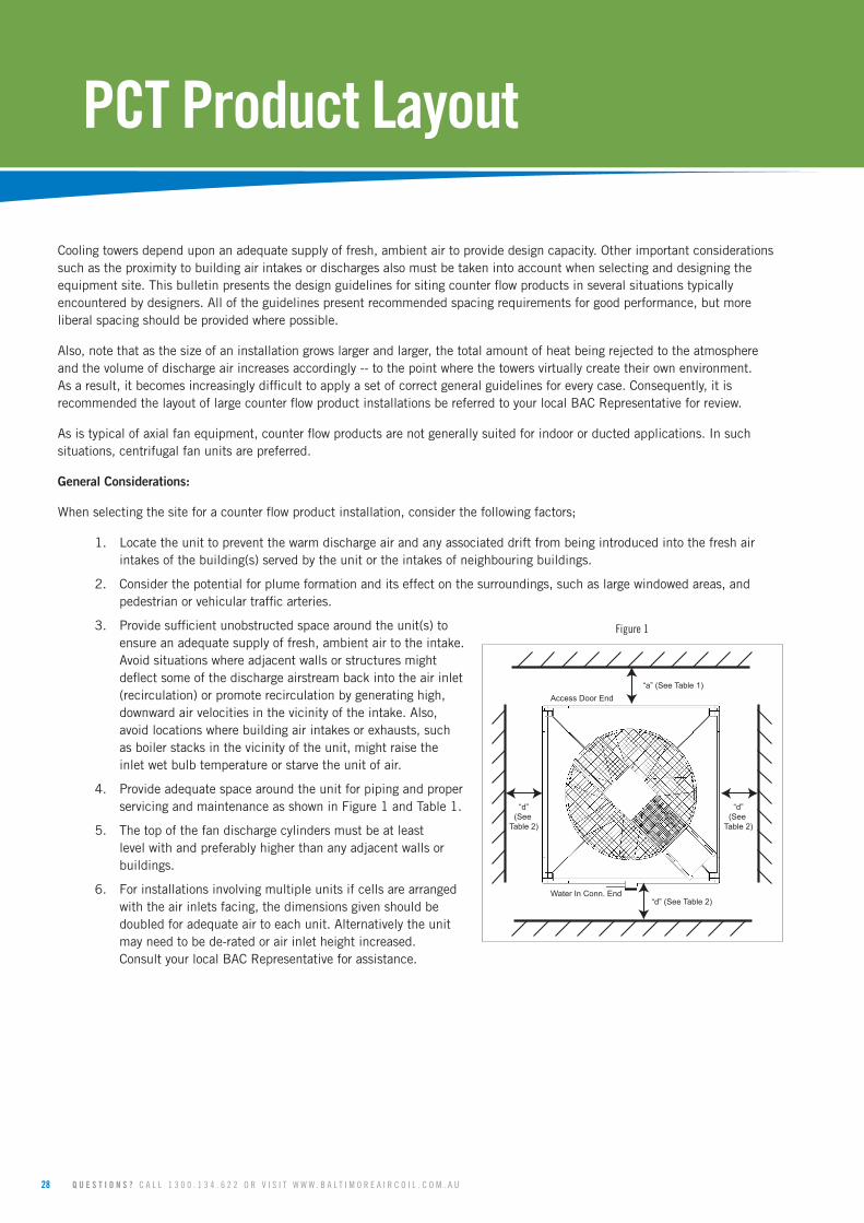
4. Provide adequate space around the unit for piping and proper servicing and maintenance as shown in Figure 1 and Table 1.
5. The top of the fan discharge cylinders must be at least level with and preferably higher than any adjacent walls or buildings.
6. For installations involving multiple units if cells are arranged with the air inlets facing, the dimensions given should be doubled for adequate air to each unit. Alternatively the unit may need to be de-rated or air inlet height increased. Consult your local BAC Representative for assistance.
“a” (See Table 1)Access Door End
Water In Conn. End
“d”(See
Table 2)
“d”(See
Table 2)
“d” (See Table 2)
Figure 1

M A R 1 0 2 - 4 29
Table 1: Access Clearance
ModelNumber
Box Size(ft)
Access Clearance
“a” (m)
PCT-0505-1 5’x5’ 1.5
PCT-0606-1 6’x6’ 1.5
PCT-0707-1 7’x7’ 1.5
PCT-0808-1 8’x8’ 1.5
PCT-0909-1 9’x9’ 1.5
PCT-1010-1 10’x10’ 1.8
PCT-1111-1 11’x11’ 1.8
PCT-0710 7’x10.5’ 1.5
PCT-0812 8’x12’ 1.5
PCT-0913 9’x13.5’ 1.5
PCT-1015 10’x15’ 1.8
PCT-1116 11’x16’ 1.8
Layout Guidelines
The “Layout Guidelines” section of this bulletin describe several typical siting situations for counter flow products. If these guidelines do not cover a particular situation or if the layout criteria cannot be met, please refer the application to your local BAC Representative or Balticare sales office for review. Please indicate prevailing wind direction, geographic orientation of the unit(s), and other factors such as large buildings and other obstructions that may influence layout decisions.
The most common counter flow product installations can be divided into three basic categories, adjacent to a wall/ building, in a well, and behind louvres. The three situations are described below.
A. Adjacent to a Building or Wall
1. Unit Orientation: When a counter flow product is located near a building wall, the preferred arrangement is to have the “short” side (if applicable) facing the adjacent wall or building.
2. Clearance: Maintain clearance for access as outlined in Figure 1 and Table 1.
3. Air Inlet Requirements: Should it ever be necessary to install a unit with the air inlet facing a wall, allow a minimum “d” dimension between the tower air inlets and the wall as outlined in Figure 1 and Table 2.
Table 2: Minimum Air Inlet Distance “d” to Solid Wall or in Well
ModelNumber
Box Size(ft)
“d” (m)
PCT-0505-1 5’x5’ 0.9
PCT-0606-1 6’x6’ 0.9
PCT-0707-1 7’x7’ 0.9
PCT-0808-1 8’x8’ 1.1
PCT-0909-1 9’x9’ 1.4
PCT-1010-1 10’x10’ 1.4
PCT-1111-1 11’x11’ 1.5
PCT-0710 7’x10.5’ 1.2
PCT-0812 8’x12’ 1.4
PCT-0913 9’x13.5’ 1.6
PCT-1015 10’x15’ 1.7
PCT-1116 11’x16’ 1.8 Note: Elevating the tower has no effect on these “d” dimensions.
Model Number
Box Size(ft)
Access Clearance
“a” (m)PCT-0808-2 16’x8’ 1.5
PCT-0909-2 18’x9’ 1.5
PCT-1010-2 20’x10’ 1.8
PCT-1111-2 22’x11’ 1.8
Model Number
Box Size(ft)
Access Clearance
“a” (m)PCT-0808-3 24’x8’ 1.5
PCT-0909-3 27’x9’ 1.5
PCT-1010-3 30’x10’ 1.8
PCT-1111-3 33’x11’ 1.8
Model Number
Box Size(ft)
“d” (m)
PCT-0808-2 16’x8’ 1.5
PCT-0909-2 18’x9’ 1.8
PCT-1010-2 20’x10’ 1.8
PCT-1111-2 22’x11’ 2.0
Model Number
Box Size(ft)
“d” (m)
PCT-0808-3 24’x8’ 1.8
PCT-0909-3 27’x9’ 2.0
PCT-1010-3 30’x10’ 2.0
PCT-1111-3 33’x11’ 2.3

30 Q U E S T I O N S ? C A L L 1 3 0 0 . 1 3 4 . 6 2 2 O R V I S I T W W W . B A L T I M O R E A I R C O I L . C O M . A U
PCTCounterFlowProductLayout
B. The Well Installation
1. Unit Orientation: When a counter flow product is located in a well a) Centre the tower within the enclosure so the supply air flows uniformly to all tower air inlets. b) The top of the fan discharge cylinder must be level with or higher than the adjacent walls.
2. Clearance: Maintain clearance for access as outlined in Figure 1 and Table 1.
3. Air Inlet Requirements: To satisfy air inlet requirements in a well enclosure, allow a minimum “d” dimension between the tower air inlets and the wall as outlined in Figure 2 and Table 2.
C. The Louvred or Slotted Wall Installations:
Check to see if the layout meets the requirements for a well installation. If the criteria for the well location are met, the layout is satisfactory. If the layout does not satisfy the criteria for the well installation, analyse the layout as follows:
1. Unit Orientation: When a counter flow product is located in a louvred enclosure a) Arrange the tower air intakes to directly face louvres. b) The top of the fan discharge cylinder must be level with or higher than the adjacent walls.
2. Clearance: Maintain clearance for access as outlined in Figure 1 and Table 1.
3. Air Inlet Requirements:
1 m
1 m 1 m
“d” (See Table 2)
“d”(See
Table 2)
“d”(See
Table 2)
1 m
Louvred Wall
1 m
Figure 3 - Louvred enclosure installation
“d” (See Table 2)
“d”(See
Table 2)
“d”(See
Table 2)
“d” (See Table 2)
Figure 2 - Well Installation

M A R 1 0 2 - 4 31
To satisfy air inlet requirements when a counter flow product is located in a louvred enclosure a) Maintain distances as shown in Figure 3. b) Louvres must provide at least 50% net free area. c) Determine the louvre or slot area required based on drawing the airflow through the net free area of the louvres at a velocity of 3 m/s or less. Calculate the louvre velocity as follows:
Louvre Velocity = Total Unit Airflow (m3/s) < 3 m/s
% louvre free area x gross louvre area (m2)
Extending the louvred or slot area below the base of the tower if needed is acceptable to achieve the minimum gross louvre area required. The tower, however, must be elevated above the base of the enclosure to satisfy requirements 1b above. The usable louvred or slot area may also be extended beyond the ends of the towers as shown in Figure 4.
1.2 m 1.2 m
1 m
Figure 4 - Usable louvred area
32 Q U E S T I O N S ? C A L L 1 3 0 0 . 1 3 4 . 6 2 2 O R V I S I T W W W . B A L T I M O R E A I R C O I L . C O M . A U
›› 1.0OpenCoolingTower›` 1.1 GENERAL:
Furnish and install ____factory assembled, induced draft, counter-flow, axial fan, open cooling tower(s) with vertical air discharge, conforming in all aspects to the specifications and schedules as shown on the plans. Overall dimensions shall not exceed approximately ____m long x ____m wide x ____m high. The total connected fan horsepower shall not exceed ____kW. The cooling tower(s) shall be Baltimore Aircoil Company Model(s) ________________.
›` 1.2 THERMAL CAPACITY: The open cooling tower(s) shall be warranted by the manufacturer to perform each and every duty listed below. Duty (a) Cool ______l/s of water from ____°C to ____°C at ____°C entering wet-bulb Duty (b) Cool ______l/s of water from ____°C to ____°C at ____°C entering wet-bulb Duty (c) Cool ______l/s of water from ____°C to ____°C at ____°C entering wet-bulb Additionally, the thermal performance shall be certified by the Cooling Technology Institute in accordance with CTI Certification Standard STD-201. Lacking such certification, a field acceptance test shall be conducted within the warranty period in accordance with CTI Acceptance test code ATC-105 by a qualified third party testing agency to determine if the tower can achieve the nearest one of the above conditions. A manufacturer’s performance guarantee or performance bond will not be accepted.
›` 1.3 QUALITY ASSURANCE: The manufacturer shall have a Management System certified by an accredited registrar as complying with the requirements of ISO-9001 to ensure consistent quality of products and services. Manufacturers that are not ISO-9001 certified shall not be acceptable.
›› 2.0ConstructionDetails
Casing›` 2.1 CORROSION RESISTANT STANDARD CONSTRUCTION:
Casing panels and supporting structure shall be constructed of superior strength pultruded composite. All pultruded composite components shall be moulded to exacting standards with UV resistant polyester resins such that the UV protection is afforded throughout the entire embodiment of the components as well as being an externally applied coating. All internal component supports shall be constructed of Type 304 Stainless Steel. All hardware joining steel parts shall be of Type 304 Stainless Steel.
›` (ALTERNATE 2.1) CORROSION RESISTANT TYPE 316 STAINLESS STEEL CONSTRUCTION: Casing panels and supporting structure shall be constructed of superior strength pultruded composite. All pultruded composite components shall be moulded to exacting standards with UV resistant polyester resins such that the UV protection is afforded throughout the entire embodiment of the components as well as being an externally applied coating. All internal component supports shall be constructed of Type 316 Stainless Steel. All hardware joining steel parts shall be of Type 316 Stainless Steel.
FanCowlandMechanicalEquipment›` 2.2 CORROSION RESISTANT STANDARD CONSTRUCTION:
Fan cowl sections shall be constructed of high performance Fibreglass Reinforced Polyester (FRP) and reinforced in critical areas. Sections shall be fastened together with Type 304 Stainless Steel hardware. All mechanical equipment supporting structure parts shall be constructed of ZAM coated steel. The fan shaft shall be of Type 316 Stainless Steel.
PCTEngineeringSpecifications
M A R 1 0 2 - 4 33
›` (ALTERNATE 2.2) CORROSION RESISTANT TYPE 304 STAINLESS STEEL CONSTRUCTION: Fan cowl sections shall be constructed of high performance Fibreglass Reinforced Polyester (FRP) and reinforced in critical areas. Sections shall be fastened together with Type 304 Stainless Steel hardware. All mechanical equipment supporting structure parts shall be constructed of Type 304 Stainless Steel. The fan shaft shall be of Type 316 Stainless Steel.
›` (ALTERNATE 2.2) CORROSION RESISTANT TYPE 316 STAINLESS STEEL CONSTRUCTION: Fan cowl sections shall be constructed of high performance Fibreglass Reinforced Polyester (FRP) and reinforced in critical areas. Sections shall be fastened together with Type 316 Stainless Steel hardware. All mechanical equipment supporting structure parts shall be constructed of Type 316 Stainless Steel. The fan shaft shall be of Type 316 Stainless Steel.
ColdWaterBasin›` 2.3 COLD WATER BASIN:
The cold water basin shall be constructed of high performance Fibreglass Reinforced Polyester (FRP) with smooth internal surfaces and reinforced in critical areas. All connections and other steel parts in the wetted area shall be constructed of Type 304 Stainless Steel. Standard basin accessories shall include: a corrosion resistant make-up valve with large diameter plastic float for easy adjustment of the operating water level, removable anti-vortexing strainer with perforated openings sized smaller than the water distribution system nozzles.
›` (ALTERNATE 2.3) The cold water basin shall be constructed of high performance Fibreglass Reinforced Polyester (FRP) with smooth internal surfaces and reinforced in critical areas. All connections and other steel parts in the wetted area shall be constructed of Type 316 Stainless Steel. Standard basin accessories shall include: a corrosion resistant make-up valve with large diameter plastic float for easy adjustment of the operating water level, removable anti-vortexing strainer with perforated openings sized smaller than the water distribution system nozzles.
›` 2.4 AIR INLET LOUVRE SCREENS: All louvres shall be constructed from PVC. Louvre sections shall be individually removable in sections of no greater than 48” wide, allowing for quick and easy access to any part of the cold water basin without the need for tools. Louvres shall prevent debris and sunlight from entering the cold water basin as well as preventing splash out. Louvres which require tools for removal shall not be an acceptable alternative.
›` 2.5 CASING FIELD JOINT: The field joint shall be self aligning and require a minimum number of fasteners.
›` 2.6 HEAT TRANSFER SECTION: The heat transfer section(s) shall consist of fill, spray water distribution system and drift eliminators arranged for optimal thermal performance with minimal drift.
›` 2.7 FILL: The fill shall be formed from self-extinguishing Polyvinyl Chloride (PVC) having a flame spread rating of <20 per ASTM E84 and shall be impervious to rot, decay, and fungus or biological attack. The fill shall be performance tested by the cooling tower manufacturer to assure single source responsibility and control of the final product. The fill shall be able to withstand a water temperature of 140°F (60.0º C).
›` 2.8 WATER DISTRIBUTION SYSTEM: Water shall be distributed evenly over the fill by a water distribution system consisting of a header and spray branches of Schedule 40 PVC pipe with large orifice, non-clog plastic distribution nozzles. The spray nozzles shall be held in place by snap-in rubber grommets and the branches should be removable without tools or removal of branch supports, allowing quick removal of individual nozzles or complete branches for cleaning or flushing. Branches that require tools for removal or removal of branch supports shall not be an acceptable alternative.
›` 2.9 DRIFT ELIMINATORS: Eliminators shall be constructed of PVC and shall be UV resistant and impervious to rot, decay and fungus or biological attacks. They shall consist of high efficiency three pass wave formed blades solvent welded into lightweight, easily removable sections. Drift loss shall be less than 0.002% of the circulated water flow as required by AS3666.
34 Q U E S T I O N S ? C A L L 1 3 0 0 . 1 3 4 . 6 2 2 O R V I S I T W W W . B A L T I M O R E A I R C O I L . C O M . A U
PCTEngineeringSpecifications
›› 3.0MechanicalEquipment›` 3.1 FAN(S):
Fan(s) shall be axial flow with glass reinforced polypropylene or glass reinforced polyamide blades selected to provide optimum cooling tower thermal performance with minimal sound levels. Air shall discharge through a fan cylinder designed for streamlined air entry and minimum tip clearance for maximum fan efficiency. The top of the fan cylinder shall be equipped with a non-sagging removable fan guard. The fan(s) and fan drive system, including the fan motor, shall be factory test-mounted and aligned to ensure reliable operation and ease of maintenance.
›` 3.2 BEARINGS (BELT DRIVEN UNITS): Fan(s) and shaft(s) shall be supported by heavy-duty, self-aligning, grease packed ball bearings with moisture proof seals and integral slinger collars, designed for L- 10 Life. Extended bearing lube lines shall be fitted for ease of maintenance.
›` 3.3 FAN DRIVE: The fan shall be either direct driven or belt driven. Where belts are used they shall be standard “A” or “B” section belts for ease of availability and be designed for 150% of the motor nameplate horsepower.
›` 3.4 FAN MOTOR (DIRECT DRIVE UNITS): Fan motor(s) shall be MEPS2 2006 compliant and be Totally Enclosed Air Over (TEAO), reversible, squirrel cage, ball bearing type, epoxy coated and be to IP66 protection rating. The motor(s) shall be mounted above the fan, protruding the top of the fan cowl for ease of access for lubrication and maintenance.
›` (ALTERNATE 3.4) FAN MOTOR (BELT DRIVE UNITS): Fan motor(s) shall be MEPS2 2006 compliant and be Totally Enclosed Fan Cooled (TEFC), reversible, squirrel cage, ball bearing type and be to IP55 protection rating. A removable protective cover shall protect the motor from the elements. Motor adjustments shall be made from the exterior of the unit. Internally mounted motors shall not be an acceptable alternative.
›› 4.0Access›` 4.1 TOWER ACCESS:
One full side of the casing shall be removable to provide full and open access to all internal tower components for inspection, maintenance and cleaning. The access panel shall be retained by four easily removable knobs and when removed shall not compromise structural integrity of the tower.
›› 5.0Sound›` 5.1 SOUND LEVEL:
To maintain the quality of the local environment, the maximum sound pressure levels (dB) measured 15m from the cooling tower operating at full fan speed shall not exceed the sound levels detailed below. Location 63 125 250 500 1000 2000 4000 8000 dB(A)
Discharge
AirInlet
›› 6.0Accessories›` 6.1 BASIN HEATER(S):
The cooling tower cold water basin shall be provided with electric heater(s) to prevent freezing in low ambient conditions. The heater(s) shall be ______kW ______V/____phase/___Hz electric and shall be provided with a thermostat.

M A R 1 0 2 - 4 35
›` 6.2 BASIN WATER LEVEL CONTROL: The cooling tower manufacturer shall provide an Electric Water Level Control (EWLC) system. The system shall consist of an electric float switch with stainless steel stilling chamber and a brass body solenoid valve in quantities and locations as indicated on the drawings. The system shall be capable of handling water pressures ranging from 0.3 – 10 bar and accept 240V/1PH/50Hz power supply. Electrical enclosures shall be of IP65 protection and the float switch shall be of single pole single throw type. The valve shall have female BSP threaded connections and shall be slow closing and of a water hammer damped type.
›` (ALTERNATIVE 6.2) BASIN WATER LEVEL CONTROL: A liquid level control device shall be fitted externally to the cooling tower basin to maintain adequate water level through a pilot operated valve. The device shall consist of an externally mounted stilling chamber with float mechanism and controller valve, and a pilot operated make up valve fitted to the cooling tower make up connection.
›` 6.3 VIBRATION CUTOUT SWITCH: A mechanical local reset vibration switch shall be fitted to the mechanical assembly of the cooling tower. It shall be designed to trip at a point so as not to cause damage to the cooling tower. The switch time delay and trip point shall be preset to typical values. Adjustment for these settings shall be available.
›` (ALTERNATIVE 6.3) VIBRATION CUTOUT SWITCH: An electronic remote reset vibration switch with contact for BAS monitoring shall be fitted to the mechanical assembly of the cooling tower. Wiring shall be by the installing contractor. The electronic vibration cut out switch shall be set to trip at a point so as not to cause damage to the cooling tower. The switch time and trip point shall be preset to typical values. Adjustment of these settings shall be available.
›` 6.4 BASIN SWEEPER PIPING: The cold water basin of the cooling tower shall be equipped with PVC basin sweeper piping suitable for use with a filter or separator (supplied by others).
›` 6.5 EXTENDED FAN COWL: The unit shall be equipped with a ZAM cylinder fitted to the top of the fan cowl suitable for connecting duct work.
›` 6.6 EXTERNAL ACCESS – ROOF DECK ACCESS POD: Provide an external ZAM access pod at the roof deck level of the unit(s) to allow access to the drive system. A hot-dip galvanised ladder from unit footing height to the pod at 15 deg to vertical shall be included. Field installation is by others. The installation shall be designed in accordance with AS 1657-1992.
›› 7.0EquipmentControls›` 7.1 VARIABLE SPEED DRIVE(S):
A Variable Speed Drive (VSD) shall be provided for each fan motor. It shall be factory mounted externally to the unit and be pre-wired and set to the required duty. The supplier of the VSD shall be the manufacturer of the evaporative cooling equipment. The VSD shall have 98% basic energy efficiency, sleep mode, automatic energy optimisation, flow compensation, and have a removable control panel. The drive shall be to IP66 protection rating and be capable of running at full load at temperatures up to 50°C.

COOLINGTOWERS
CLOSED CIRCUIT COOLING TOWERS
ICE THERMAL STORAGE
EVAPORATIVE CONDENSERS
HYBRID PRODUCTS
PARTS & SERVICES
w w w . B a l t i m o r e A i r c o i l . c o m . a u
120 Wisemans Ferry Road, Somersby NSW 2250 › Telephone (Australia): 1300.134.622 › Telephone (New Zealand): 0800.225.842