pd10-m-cvr -...
TRANSCRIPT

PD10-M-CVR
Doc # 20201
1
I N S T A L L A T I O N I N S T R U C T I O N S
Visit our website for more detailswww.CommandAccess.com
U.S. Customer Support1-888-622-2377
Canada Customer Support1-855-823-3002
A.
PD10-M- C VR I ncludesA. Head Cover packB. CVR Exit DeviceC. Concealed Vertical RodsD. Hinge Stile End Cap packE. Strike packF. Retractor & Pinion packG. Traveler packH. MM3 - Installed in exit deviceI. 6’ Power Lead
Tools Required• Cordless Drill• Needlenose Pliers• Measuring Tape• 1/2 Drill bit
The PD10-M-CVR is a storefront grade 1 exit device equipped with motor drive latch retraction. Retrofits
Doromatic 1690 & First Choice 3690.
B.
D. E. F.
C.
G.H.
I.
2
Doc # 20201
Visit our website for more detailswww.CommandAccess.com
U.S. Customer Support1-888-622-2377
Canada Customer Support1-855-823-3002
T E C H N I C A L I N F O R M A T I O N
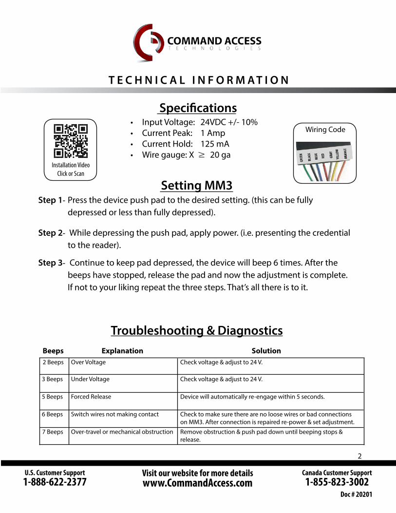
Specifications• Input Voltage: 24VDC +/- 10%• Current Peak: 1 Amp• Current Hold: 125 mA• Wire gauge: X 20 ga
2 Beeps
3 Beeps
5 Beeps
6 Beeps
7 Beeps
Beeps Explanation SolutionOver Voltage
Under Voltage
Forced Release
Switch wires not making contact
Over-travel or mechanical obstruction
Check voltage & adjust to 24 V.
Check voltage & adjust to 24 V.
Device will automatically re-engage within 5 seconds.
Check to make sure there are no loose wires or bad connections on MM3. After connection is repaired re-power & set adjustment.
Remove obstruction & push pad down until beeping stops & release.
Step 1- Press the device push pad to the desired setting. (this can be fully depressed or less than fully depressed).
Step 2- While depressing the push pad, apply power. (i.e. presenting the credential to the reader).
Step 3- Continue to keep pad depressed, the device will beep 6 times. After the beeps have stopped, release the pad and now the adjustment is complete. If not to your liking repeat the three steps. That’s all there is to it.
Troubleshooting & Diagnostics
Setting MM3
Wiring Code
Installation VideoClick or Scan

3
Module
Ceiling Tile
Legend
Optional ModulePlacement
Standard Placement
Optional Placement
Module
Electrified Exit DeviceInstallation Example
RECOMMEND POWER SUPPLIES:All Command Access exit devices & field installable kits have been thoroughly cycle tested with Command Access power supplies at our factory. • PS1• PS2/2BB
• PS5-4• PS5-6
• PS5-8
For more information click here or go to our website

4
Concealed Vertical RodFor Bottom Rod LatchInstallation Template
All prep is shown on interior side of the door, except where noted.
Right hand door shown. (LHR)
5
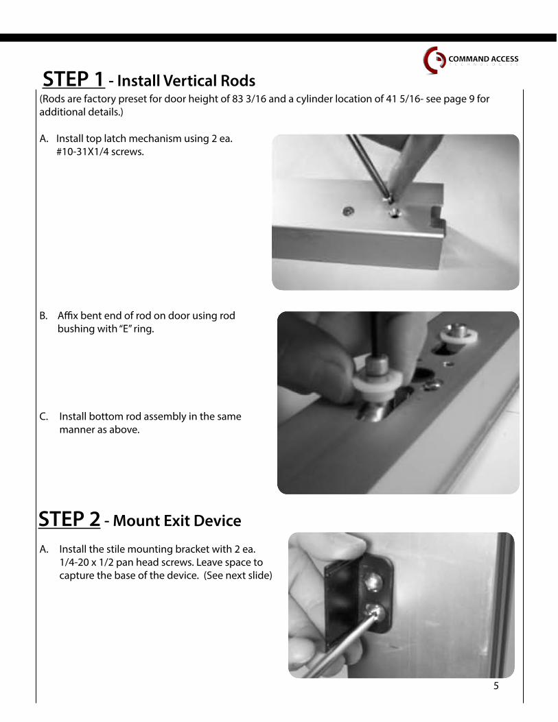
(Rods are factory preset for door height of 83 3/16 and a cylinder location of 41 5/16- see page 9 for additional details.)
Install top latch mechanism using 2 ea. #10-31X1/4 screws.
Install bottom rod assembly in the same manner as above.
Affix bent end of rod on door using rod bushing with “E” ring.
Pic 3
STEP 1 - Install Vertical Rods
A.
B.
C.
Install the stile mounting bracket with 2 ea. 1/4-20 x 1/2 pan head screws. Leave space to capture the base of the device. (See next slide)
A.
STEP 2 - Mount Exit Device
6
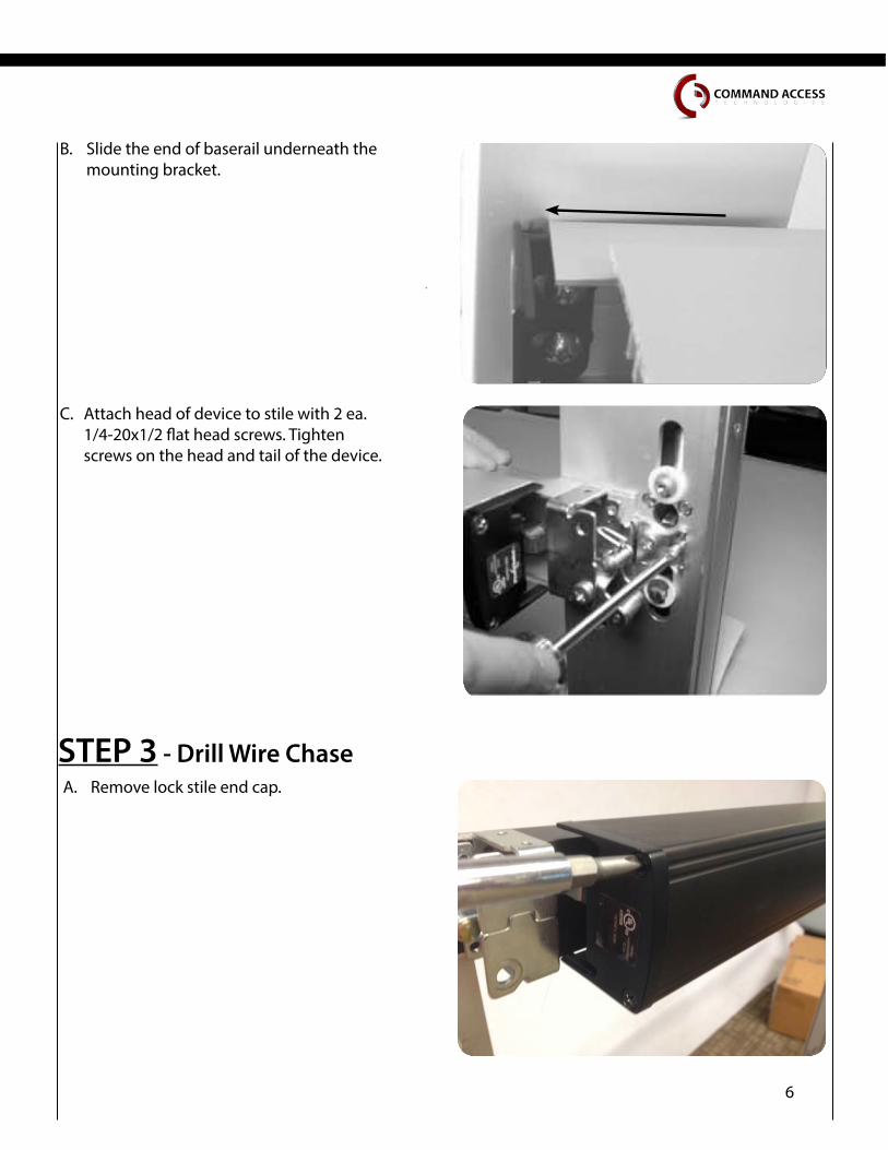
Slide the end of baserail underneath the mounting bracket.
Attach head of device to stile with 2 ea. 1/4-20x1/2 flat head screws. Tighten screws on the head and tail of the device.
B.
C.
Remove lock stile end cap.
STEP 3 - Drill Wire ChaseA.

7
Slide push pad off of baserail.
Drill the hole for our 2 pin power lead in-between the 2 mounting screws.
B.
C.
Feed the 2 pin power lead into the hole and connect to our MM3 module. Also, make sure to clean out any debris left.
D.
Debris
Note: Depending on where your power transfer is; next you would fish the other side of the power lead we
connected to the MM3 and hook up to your incoming power. If you have a portable tester this would be a
good time to test fire the motor.
8
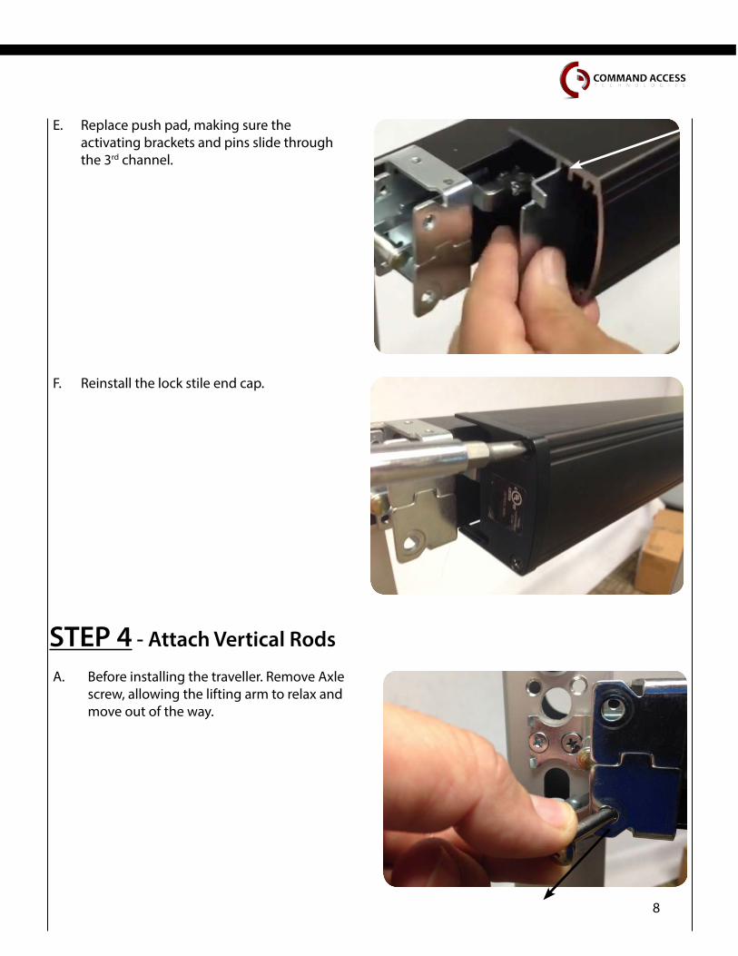
Before installing the traveller. Remove Axle screw, allowing the lifting arm to relax and move out of the way.
Replace push pad, making sure the activating brackets and pins slide through the 3rd channel.
STEP 4 - Attach Vertical Rods
E.
Reinstall the lock stile end cap.F.
A.

9
Install Pinion support bracket and tighten retainer screw.
Re-install Axle screw and tighten.
Install Traveller onto the bent end of the vertical rods.
B.
C.
D.

10
Reinstall Axle screw and tighten.
Add Retractor and Traveller lift bracket. Pick placement of pinion depending on desired function.
Place Pinion with black cylinder bushing into the door with the cylinder tail piece sliding into the back of the pinion.
Flat side of pinion facing up.
Optional STEP - Installing Cylinder
B.
C.
A.Flat Side

11
-Check Bottom Rod operation.
The bottom latch should not protrude more than 1/16 inch below the bottom of the door when the push pad is depressed.
-Check Top Rod operation.
When push pad is depress fully, top latch should open and allow top strike to pass, and swing freely.
Install Pinion support bracket and tighten retainer screw.
D.
STEP 4 - Continued
B.
A.
Install head cover with 2 ea. 10-32 x 3/8 screws.

12
Remove the Axle screw and lifting arm.
Flip the lifting arm to the other side of the assembly. Re-install Axle screw and tighten.
Install hinge stile push pad cover with 2 ea. 8-32 x 1 1/2” screws. Now you set you latch retraction adjustment with our “PTS” technology.
See page #2
Optional STEP - How to change handing
B.
A.
C.
Lifting arm.
13
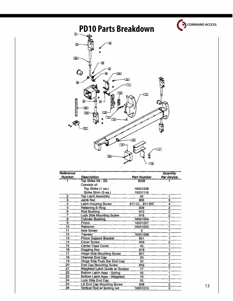
PD10 Parts Breakdown

14
Doc #20201
Visit our website for more detailswww.CommandAccess.com
U.S. Customer Support1-888-622-2377
Canada Customer Support1-855-823-3002