pdeng project report
TRANSCRIPT

PDEng Project Report
Developing a Geo-fencing based Safety System for High-pressure pipelines
Saeid Asadollahi March 2019
UNIVERSITY OF TWENTE.


Type: PDEng project Report
Project Developing a geo-fencing based safety system for high-pressure pipelines
Name Saeid Asadollahi
Employee number: m7663341
Educational institution: University of Twente
Faculty: Faculty of Engineering Technology
First supervisor: Dr. Ir. L.L. (Léon) olde Scholtenhuis
Second supervisor Dr. Ir. F. (Farid) Vahdatikhaki
Thesis supervisor: Prof. Dr. Ir. Ing. A.G. (André) Dorée
Clients: 4TU (funding) and VELIN (Problem owner)
Place: Enschede
Date: March 2019


ACKNOWLEDGEMENT First of all, I would like to thank GOD for helping me during my whole life.
I gratefully acknowledge the support, time and the effort of my supervisors, Prof.dr.ir. André Dorée, Dr.ir. Léon olde Scholtenhuis and Dr.ir. Farid Vahdatikhaki from the University of Twente. Their excellent guidance properly oriented me to successfully complete the project and my PDEng.
I would like to thank Ir. Frans Driessen and Ir. Mark Engbersen, the representatives of VELIN and the steering group members of my project.
I am pleased to express my gratitude to the VELIN, 4TU and to the Department of Construction Management and Engineering of University of Twente, that provided me the opportunity to pursue the PDEng program.
I would like to thank all of my colleagues in Construction Management and Engineering Department for enriching me with their valuable knowledge during my PDEng and I express my special thanks to Armin Langroodi for his moral and technical supports during my project.
Thanks to SOMA College, ZEBRA Gasnetwerk Company and the Gasunie of Enschede for their helpful collaboration with the University of Twente during this project.
I want to thank my lovely wife (Vahan) and my sweetheart daughter (Ayla) for their love and moral supports.
The last but not the least, my sincere thanks to my mother and my family in Iran for their love in my heart.


ii
LIST OF DEFINITIONS
Detection system A technology that is capable of locating an underground high-pressure pipeline without requiring a priori information.
End user
The person who should be alerted by the safety system, in case there is any incident risk to the high-pressure pipelines. The end user is the excavator operator or third party who carries out the excavation operation.
Geo-fence
A virtual fence that is defined around the specific object. In this project, this geo-fence identifies a risk zone around the high-pressure pipelines/excavation equipment. If an excavation equipment enters the risk zone the safety system generates an alarm.
High-pressure pipeline A transportation high-pressure pipeline which carries dangerous substances.
Monitoring system A technology that integrates known locations of a high-pressure pipelines and tracked excavation location to anticipate high-pressure pipeline incidents.
High-pressure pipeline incident Damage to an underground high-pressure pipeline, and its direct surrounding, caused by excavation work.
Prototype A prototype is an early sample or model of a product built to test a concept or process or to act as a thing to be replicated or learned from.
Real Time Localization System (RTLS) A positioning system to track location of objects.
Safety system A system which is designed to protect high-pressure pipelines from incidents.
Stakeholder A person, company or organization who can affect the design or be affected by the design.
Third party A person or organization who executes the excavation operation close to high-pressure pipelines but is not directly hired by the high-pressure pipeline owner.
Transportation high-pressure pipeline
High-pressure steel high-pressure pipelines that carry hazardous substances (e.g. oil and gas).
Validation A test to check if the design meets the stakeholder’s requirements.
Verification A test to check if the design meets the specified system requirements.
Alarm system The actual technology that processes detection/monitoring signals and triggers the alarm for excavation equipment operators or high-pressure pipeline owners.

iii
LIST OF ABBREVIATIONS
CONCAWE European Oil Company Organization for Environment, Health, and Safety
EGIG
GLONASS
European Gas Incident Group
GLObal NAvigation Satellite System
GNSS Global Navigation Satellite System
GPS Global Positioning System
I&W Infrastructuur en Waterstaat (Ministry of Infrastructure and Water Management)
KLIC Kabel en Leidingen Informatiecentrum. The Dutch dial-before-you-dig center; One Call System
NETPOS Netherlands Positioning Service
NTRIP Networked Transport of RTCM via Internet Protocol
RTK Real Time Kinematic
RTLS Real Time Localization System
VELIN Association of high-pressure pipeline owners in the Netherlands

iv
PREFACE
This PDEng project is a part of the Safety Deal which is an initiative by Ministry of Infrastructure and Water Management (I&W) to reduce the number of excavation damages to underground high-pressure pipelines. Prior to this PDEng, I worked on a research project to provide an overview of existing detection and monitoring technologies to protect underground utilities from excavation damages. That research was sponsored by the VELIN (association of high-pressure pipelines owners in the Netherlands) and was done in Construction Management and Engineering Department of University of Twente. As a result of the research work, the ZoARG team of the University of Twente decided to do a follow up project and defined a PDEng project to develop a geo-fencing based safety system for high-pressure pipelines. Fortunately, the number of high-pressure pipelines incidents in Europe is not high, but the impact of any incident can be extremely high. In addition to causing huge financial loss which can be up to a few million euros, these incidents sometimes lead to injuries and even fatalities. According to the report from EGIG (2015) and CONCAWE (2013), the most common cause of high-pressure pipelines incidents are the third parties. Third party is a person who carries out the excavation operation close to the high-pressure pipelines and is not hired directly by a high-pressure pipelines owner. The ultimate goal of the gas/energy industry is to reduce the number of incidents to zero. To achieve that, initiatives in different aspects such as technological development initiatives and behavioral training initiatives are required. This PDEng project focuses on developing a technical solution. It aims to develop a geo-fencing based safety system to help reduce the number of high-pressure pipelines incidents caused by third parties. The outcome of this PDEng project is a geo-fencing based safety system that warns the excavation equipment operator and the high-pressure pipelines owner if an excavation operation is carried out close to the high-pressure pipelines. This document is the final report of my PDEng project. Chapter 1 is the introduction to the project and presents the theoretical background. Chapter 2 explains the PDEng project problem and analysis, by defining the problem statement and the project objective. Chapter 3 explains the design methodology. Before explaining the design itself, the requirement are discussed in chapter 4. In chapter 5, the safety system architecture will be discussed. Then, chapter 6 with the ‘System Development Implementation’ title is about the detailed design. In chapter 7 the experiments results and the system validation are discussed . Chapter 8 is about the protocols that should be followed to import high-pressure pipelines data to the safety system and to use the safety system. The developed safety system is compared with other similar existing systems in chapter 9. Also the system constraints, false alarm scenarios and the impact of the safety system are discussed in chapter 9. Chapter 10 is the conclusion. Recommendations and future possibilities are discussed in chapter 11. In chapter 12, the used references are listed and Chapter 13 consists of four appendices.


v
Product summary
This chapter provides an overview of the geo-fencing based safety system by addressing these questions:
• What is the aim of developing this safety system? • Who is the target group of this safety system? • How does the safety system work? • What is the needed input for the safety system? • What is the added value of this safety system? • Who is beneficiary of this safety system?
Based on regulation anyone intending to carry out excavation activity must request for underground utility location data from the KLIC-melding service1. KLIC-melding service is an online service provider that is operated by Kadaster and provides the underground utility location information. However, inexperienced and non-trained people either do not comply, or find it still difficult to use this information for avoiding damage to the underground utilities during excavation. Therefore, the geo-fencing based safety system intends to compliment the KLIC-melding service by helping to avoid excavation damage when the third party carries out an excavation work without any information about the high-pressure pipelines location. So, the safety system should work such that it warns the third parties about the presence of high-pressure pipelines in the proximity of the excavation area. The safety system, works based on real-time tracking of the excavation equipment and the location data of high-pressure pipelines. Excavation equipment is tracked and a virtual fence (a circular buffer) is created around it. Based on the location of the excavation equipment and the location of high-pressure pipelines it is checked by the safety system in real time whether or not the buffer around the excavation equipment, known as geo-fence, collides with the location of high-pressure pipelines. If a collision is detected, the safety system alerts the excavation equipment operator and the high-pressure pipelines owner about the excavation damage risk to the high-pressure pipelines. The high-pressure pipeline’s location data is an input to the safety system. It is not in the functionality of the safety system to detect high-pressure pipelines in the field but it uses the imported high-pressure pipelines location data. Another input of the safety system is the real-time data of excavation equipment location which is gained by using a positioning technology.
Being low-cost (i.e., a few hundred euros), makes the safety system affordable for smaller scale companies and the third parties who are the main cause of excavation damages to the high-pressure pipelines. Being low cost is one fundamental benefits of the safety system for third parties.
Since the safety system works by tracking the location of the excavation equipment, the accuracy of real-time tracking is one of the important factors that affects the reliability of the safety system. A low-cost positioning system with the price in range of a few hundred euros, normally has the positioning accuracy in range of 3 to 5 meters but refer to the safety experts and asset owner’s opinion, this level of accuracy is not adequate to avoid the excavation-caused damages to the high-pressure pipelines because having 5 meter accuracy when the buffer radius is 5 meters, means that the safety system may generate the alarm when the excavation work is being carried out at the exact location of the high-pressure pipelines which is dangerous. A solution for this problem can be defining wider buffer, i.e. 10 meters, which means the safety system may generate alarm when the excavation operation is being carried out within 10 meters distance from the high-pressure pipelines. But it is a very early alarm and will be intrusive for the excavation operation. High-pressure pipelines industry experts and the client required that the system is non-intrusive for the excavation operation. Hence, having one meter/sub meter accuracy is an important requirement for the safety system. Despite being a low-cost safety system, since 1 KLIC-melding is formally either an orientatiemelding (orientation request for planning work) or graafmelding (announcement for excavation activity start). In the word of most practitioners, they refer to these as KLIC-melding.

vi
the geo-fencing based safety system can provide the accuracy of one meter, it makes the safety system reliable for the users. Many of detection and monitoring technologies are not compatible with the pace of excavation work and to use the technology a preparatory work is required. It makes the use of these technologies intrusive to the excavation operation. But using the safety system does not require an extra effort from the excavator operator and it is not intrusive to his work. Last but not the least, the user interface is very simple and understandable for the operators. In many of the detection and monitoring systems, the output data of the system is not understandable for non-professional users and needs an expert’s interpretation. In geo-fencing based safety system, I tried to make the interface understandable for non-professional users such as third parties. The aim is having a just sufficient interface to alert the user. This simplicity prevents misinterpretation of the safety system output.
The association of high-pressure pipelines owners in the Netherlands (VELIN) encounters a huge loss when an incident to the high-pressure pipelines happens. The geo-fencing based safety system is beneficial for them to keep their asset safe and consequently to get more societal support from public. Although the aim of developing the safety system is not directly helping third parties, avoiding excavation damages caused by this group is beneficial for them. However, this group can benefit from the safety system by being alerted about the potential dangers. In addition to the stakeholders that directly benefit from the safety system, the construction contractors and their employees, excavation machinery’s owners, the ministry of infrastructure and water Management and the emergency services are other stakeholders that indirectly benefit from the safety system. Furthermore by adding another layer of defense to avoid strikes, the damage to the people and nature is also avoided.

ix
Graphical summary To have an overview of the project, a project infographic was created. Figure (a) shows the infographic of the geo-fencing based safety system.
Figure a. The infographic of Geo-fencing based safety system


x
Management summary This PDEng project is an initiative, as a part of the Safety Deals conducted by VELIN (association of high-pressure pipelines owners in the Netherlands), to reduce excavation damages to high-pressure pipelines. In this project the aim is to help reduce the excavation damages to high-pressure pipelines caused by third parties. Considering this aim a safety system was developed that works based on real-time monitoring and geo-fencing. The problem investigation results indicated that the time, cost, complexity and extra effort are the main causes of the third party’s failure to use the high-pressure pipelines location data or to use existing detection and monitoring systems before carrying out the excavation operation. Example of issues with time is that the procedure of receiving the high-pressure pipelines location data from KLIC-melding service is not in real time. Example of the complexity issues is that the user interface of some technologies such as Ground Penetrating Radar (GPR) is non-understandable for non-professional users. In terms of cost, the monitoring technologies that provide a real-time monitoring are not low cost and when they are, their accuracy level is low. So, it was figured out by design team that to reduce the number of high-pressure pipelines incidents caused by third parties, a solution should address aforementioned issues. Based on problem investigation and defining the requirement, the design team decided to develop a geo-fencing based safety system. Although in developing the geo-fencing based safety system the main focus is on cost and accuracy, other issues such as extra effort and complexity were taken in consideration. The geo-fencing based safety system is a plug and play safety system that uses the existing data of high-pressure pipelines location. It tracks the excavation equipment and in real time checks any collision possibility between the location of the excavation equipment and the high-pressure pipelines.
The geo-fencing based safety system was presented for the client and the high-pressure pipelines industry experts during two workshops and four meetings. Also, the functionality of the safety system was validated during 20 experiments. Furthermore a system demonstration test was done successfully with presence of high-pressure pipelines industry representatives. Based on the result of the experiments, the overall impression of the candidates is that the implementation of the geo-fencing based safety system as a complementary tool to KLIC-melding service has potential to reduce the number of high-pressure pipelines incidents. In contrast with many existing high-pressure pipelines safety technologies that require preparatory work, impose extra effort on operators and lack real-time support, the geo-fencing based safety system is a plug and play safety system that works in real time and requires no effort from third party during the excavation operation.
In terms of implementation of the safety system in excavation industry, reducing the number of incidents and having safer excavation operation as a result of using geo-fencing based safety system will motivate the construction and pipelines industry to adopt it. However to implement the safety system, it is better to implement it first in smaller scale as a pilot implementation. The pilot implementation helps identify and solve the potential existing issues of the safety system related to its functionality, reliability and its effectiveness. In terms of the reliability of the safety system, the level of accuracy and the number of generated false alarms are important. The safety system is reliable if it is accurate and the number of generated false alarms is not annoying for the user. When the geo-fencing based safety system is accepted by the high-pressure pipelines owners and the construction industry, it can be implemented on a larger scale. To implement the safety system successfully in a larger scale, it is eventually necessary to persuade contractors and machine owners to mount the safety system on their equipment. However it is difficult to control every each of the excavation equipment whether or not it is equipped with geo-fencing based safety system. The recommended alternative is to require the equipment manufacturers or rental companies to add the safety system to their equipment.
The geo-fencing based safety system is supposed to use the existing data of high-pressure pipelines provided by Kadaster. However because of the new high-pressure pipelines installation, there will be change in data and they should be updated in data base of the safety system. In the current state of the safety system prototype, the update of high-pressure pipelines location data is offline. So the data of high-pressure pipelines location should updated manually in a certain period of time. This period of time depends of rate of change in high-pressure

xi
pipelines location. Since an internet connection has been provided in the safety system, it is possible to update the data online and make the safety system independent from manual update. Working on making data update as an online process is recommended.
It is worth mentioning that although the geo-fencing based safety system helps reduce the number of high-pressure pipelines incidents, it will not be a sufficient solution to reduce the number of incidents to zero. Similar to every each of the existing detection and monitoring technologies, the geo-fencing based safety system only helps reduce the number of excavation-caused high-pressure pipelines incidents to a certain extent. Based on the earlier research done at the University of Twente, it was concluded that none of the existing detection and monitoring technologies can alone reduce the number of high-pressure pipelines incidents to zero (Asadollahi, olde Scholtenhuis, Vahdatikhaki, & Doree, 2017).

Table of Contents 1 Introduction ____________________________________________________________________________________ 1
1.1 Background ________________________________________________________________________________ 1 1.2 Theoretical background _______________________________________________________________________ 2
2 Project Problem and Analysis ______________________________________________________________________ 5 2.1 Problem statement __________________________________________________________________________ 5 2.2 Objective __________________________________________________________________________________ 5
3 Design Methodology _____________________________________________________________________________ 6 3.1 Problem Investigation ________________________________________________________________________ 6 3.2 Solution ___________________________________________________________________________________ 6 3.3 Conceptual Design ___________________________________________________________________________ 6 3.4 Detailed Design _____________________________________________________________________________ 7 3.5 System Development _________________________________________________________________________ 7 3.6 Solution Validation __________________________________________________________________________ 7
4 System requirement analysis ______________________________________________________________________ 8 4.1 Stakeholders _______________________________________________________________________________ 8 4.2 Requirement analysis ________________________________________________________________________ 9
5 System Architecture ____________________________________________________________________________ 12 6 System Development Implementation _____________________________________________________________ 15
6.1 Design workflow ___________________________________________________________________________ 15 6.2 Positioning subsystem development ____________________________________________________________ 15 6.3 Geo-fence subsystem design development implementation _________________________________________ 16 6.4 Alarm subsystem development implementation __________________________________________________ 18 6.5 Prototype development implementation ________________________________________________________ 18
7 Experiments Result and Validation ________________________________________________________________ 20 7.1 Positioning subsystem experiments ____________________________________________________________ 20 7.2 Safety system prototype experiments ___________________________________________________________ 23
8 System Protocols _______________________________________________________________________________ 26 8.1 Input data protocol _________________________________________________________________________ 26 8.2 Safety system use protocol ___________________________________________________________________ 27
9 System Comparison, Limitations and Impact ________________________________________________________ 28 9.1 System Comparison _________________________________________________________________________ 28 9.2 System Constraints _________________________________________________________________________ 29 9.3 Safety system impact ________________________________________________________________________ 30
10 Conclusion ____________________________________________________________________________________ 31 11 Recommendations and Future work _______________________________________________________________ 33
11.1 Recommendation ___________________________________________________________________________ 33 11.2 Future possibilities __________________________________________________________________________ 34
12 References ____________________________________________________________________________________ 36 13 Appendices ____________________________________________________________________________________ 38
13.1 Appendix 1 _ System verification experiments ____________________________________________________ 38 13.2 Appendix 2_Work shop ______________________________________________________________________ 39 13.3 Appendix 3_ PDEng project Timetable __________________________________________________________ 42 13.4 Appendix 4_ Publications ____________________________________________________________________ 43

List of figures Figure 1. Categorization of the detection and monitoring technologies __________________________________________ 2 Figure 2. Schematic overview of single solution positioning technique __________________________________________ 3 Figure 3. Schematic overview of RTK-based solution positioning technique ______________________________________ 3 Figure 4. Netherlands Positioning Service (Kadaster, 2005) ___________________________________________________ 4 Figure 5. Object positioning based on RTK solution (“Kadaster,” 2018) __________________________________________ 4 Figure 6. Design cycle and Engineering cycle _______________________________________________________________ 6 Figure 7. Stakeholders of the geo-fencing based safety system project __________________________________________ 8 Figure 8. Needs and Requirements related to geo-fencing based safety system ___________________________________ 1 Figure 9. Schematic explanation of initial design of geo-fencing based safety system _____________________________ 12 Figure 10. Schematic explanation of a geo-fencing based safety system ________________________________________ 12 Figure 11. Safety system sequential diagram ______________________________________________________________ 13 Figure 12. Workflow of design _________________________________________________________________________ 15 Figure 13. U-blox unit as a component of positioning subsystem ______________________________________________ 16 Figure 14. Workflow of Python code _____________________________________________________________________ 17 Figure 15. Raspberry Pi as a hardware of geo-fence subsystem _______________________________________________ 18 Figure 16. Hardware components of geo-fencing based safety system _________________________________________ 19 Figure 17. Flowchart of the design procedure _____________________________________________________________ 20 Figure 18. Coordinates distribution compared to the ground truth for a stationary object __________________________ 21 Figure 19. Positioning experiment location on the University Campus __________________________________________ 22 Figure 20. Coordinates distribution compared to the ground truth at 5km/h and 13km/h rover movement speed _______ 22 Figure 21. Radar chart of positioning experiment results ____________________________________________________ 23 Figure 22. Decision tree to validate generated alarms by the safety system prototype _____________________________ 24 Figure 23. Layers of data in a high-pressure pipelines location file _____________________________________________ 26 Figure 24. The blue light on the U-blox unit _______________________________________________________________ 27 Figure 25. The constant blue light on internet dongle that shows the internet connectivity _________________________ 27 Figure 26. Three work packages for development of a multi layered safety system _______________________________ 33 Figure 27. Test of the safety system prototype in hypothetical condition ________________________________________ 38 Figure 28. Test of the safety system prototype in an actual high-pressure pipeline location _________________________ 38 Figure 29. System prototype demo test in an actual excavation condition at SOMA College with audience from VELIN ___ 39 Figure 30. Timetable of the PDEng project ________________________________________________________________ 42
List of tables Table 1. Stakeholders of the geo-fencing based safety system project ___________________________________________ 8 Table 2. The best achieved accuracy and precision in positioning subsystem test at 5 and 13km/h rover movement speed 23 Table 3. Result of system prototype reliability measurement _________________________________________________ 25 Table 4. System comparison ___________________________________________________________________________ 28 Table 5. Plan of Geo-fencing project workshop ____________________________________________________________ 40

1
1 Introduction 1.1 Background The Netherlands has an extensive underground infrastructure of cables and pipelines (Harmsen & Emous, 2006; Kadaster, 2016; Koppens, 2013). One specific type of this buried infrastructure is the transportation network for hazardous material such as gas, oil, and chemicals. This network comprises 22.000 kilometers of high-pressure transportation pipelines (“VELIN,” 2017). High-pressure pipelines that carry hazardous substances are located underground and therefore are vulnerable to damages during excavation work. Although buried pipes are protected by the ground, this same environment makes pipes invisible to the eyes of the operators who conduct groundwork activities. The operations of excavation and digging equipment are therefore a potential cause of high-pressure pipelines incidents (Asadollahi, olde Scholtenhuis, Vahdatikhaki, & Dorée, 2017; Rogers, Chapman, Royal, Metje, & Atkins, 2012). Different groups may be injured when high-pressure pipelines incidents occur. According to European Gas Incidents Group (2015), these groups are:
• Employees of contractors or the operators . • Emergency services (firefighters, medical assistance). • The general public.
The most recent serious incidents in the Netherlands and its surrounding countries are: • 2004 Gas high-pressure pipeline explosion in Ghislenghien, Belgium. Incident caused by an excavation
equipment during the construction of a parking place. • 2010 Spillage from a crude oil high-pressure pipeline in Vlake (Zeeland), Netherlands. Incident caused by
a drainage machine. • 2013 Leak from a naphtha high-pressure pipeline near the Juliana Canal in Stein (Limburg), Netherlands.
Incident caused by auger activities. • 2014 Explosion of gas high-pressure pipeline in Ludwigshafen, Germany. Incident caused by the
excavation activities.
Fortunately, the frequency of the high-pressure pipelines incidents in the Europe is low, but the consequences of these incidents are significant (CONCAWE, 2013; Gasunie, 2015; OSYS technology limited, 2009). High-pressure pipelines incidents can cause fatalities to excavation workers and have an impact on the environment. Only the direct costs for the recovery of damages are estimated by the high-pressure pipelines owner association (VELIN) to range from several hundred or thousands to even a few millions of euros (Harmsen & Emous, 2006). Serious incidents will eventually undermine the public’s acceptance of hazardous high-pressure pipelines, so it goes without saying that high-pressure pipelines excavation incidents should be avoided (Asadollahi et al., 2017). From the year 2008, everyone who wants to carry out an excavation activity in the Netherlands, is obliged to request the data of buried infrastructure within the excavation location. This should be done via KLIC-melding service. In addition, there are several existing underground utility detection and monitoring technologies to protect utilities from excavation damage. Despite such risk mitigation measures, still excavation damage to the underground infrastructure happens. The main cause of high-pressure pipelines damages are excavation activities conducted by the excavation equipment operators who are not hired by the high-pressure pipelines owners, known as third parties (Capstick, 2007; CONCAWE, 2013; European Gas Incidents Group, 2015; Muggleton & Rustighi, 2013). One of the reasons for these incidents as often mentioned by the industry, is that requesting the utility location information via the KLIC information center (KLIC-melding service) is not in real time. It means that after requesting the high-pressure pipelines location data it takes time to get the data. Another reason is that the excavation equipment operator sometimes misinterprets the provided high-pressure pipelines location data (Harmsen & Emous, 2006). Carrying out the excavation without having the high-pressure

2
pipelines location data and misinterpreting the high-pressure pipelines location data, increases the risk of incidents. Initiatives are needed to protect underground utility from excavation damage by use of detection and monitoring techniques.
The association of high-pressure pipelines owners in the Netherlands (VELIN) and the Dutch Ministry of Infrastructure and Water Management (I&W) took initiative, known as Safety Deals, to reduce the excavation damages to the high-pressure pipelines. One stream of the Safety Deals is the identification and development of technologies for high-pressure pipelines damage avoidance. As a part of this stream the University of Twente has a collaboration with VELIN. In the first phase of this collaborative work, the Construction Management and Engineering Department of the University of Twente provided an overview of all the existing underground utility detection and monitoring technologies and the current state of the collaboration as the second phase is about developing a safety system to help reduce the number of excavation-caused damages to the high-pressure pipelines (Asadollahi et al., 2017).
1.2 Theoretical background Detection and monitoring technologies
As shown in Figure 1, the existing excavation damage prevention technologies can be categorized into two main classes, namely detection systems and monitoring systems (Asadollahi et al., 2017; Jeong, Arboleda, Abraham, Halpin, & Bernold, 2003; Subsurface Surveys Associates, 2015). At its core, a detection system identifies the location of an underground utility by transmitting signals into and receiving them back from the ground. These systems are applied locally and at a certain moment to detect utility sections (Rogers et al., 2012). Alternatively, a monitoring system uses known underground utility location data and combines this with the ‘measured’ equipment locations to anticipate conflicts. Compared to detection systems, monitoring systems are global and permanent solutions (Okon, 2016; Wang, 2004). Within the monitoring systems category, they are further classified into two groups. One type of monitoring systems is the pipeline-centered system that uses buried detection sensors (e.g. acoustic emission sensors) to identify soil disturbances caused by excavation equipment. The second is the location-centered system that uses pipelines maps and integrates them with location information from a Real Time Localization System (RTLS) to identify potential clashes.
Figure 1. Categorization of the detection and monitoring technologies
The most promising detection technologies up to now are the electromagnetic locators (Sterling et al., 2011; Subsurface Surveys Associates, 2015). In terms of monitoring systems, fiber optic sensors and geo-fencing based systems are among the promising systems in terms of underground utility safety. Considering a safety system that can help reduce third party-caused damages to high-pressure pipelines, to motivate this target group to use the safety system, the safety system should not be intrusive to the excavation work. Also the use of the safety system should not require extra and preparation activity from the operator. In this scope the geo-fencing based safety system which is among the pipe-centered systems category seems a promising approach to protect high-pressure pipelines from excavation damages (Anspach, 2016; Asadollahi et al., 2017).
Excavation Damage Prevention System
Monitoring Systems
Detection Systems
Pull Detection systems Push Detection systems Location-based systems Pipe-centered systems

3
The safety system creates a virtual buffer (known as geo-fence) around the utility and uses a positioning technology to track excavation equipment. It warns the user when the excavation equipment enters the geo-fence. The reminder of this section discusses specific theoretical knowledge of used technologies in this project.
Positioning technology In using the geo-fencing approach, tracking the excavation equipment is a very important task. So to have a reliable geo-fencing based safety system, using an accurate and reliable positioning technology is indispensable. Two main solutions in terms of positioning solutions are single positioning and Real-Time Kinematic (RTK) positioning. In positioning, a reference station or reference stations are the points with very accurate known coordinates that are used to correct the rover received coordinates from satellites. Example of these corrections is the atmospheric correction. In the single solution, no reference station is used and the positioning is based on the satellite-gained coordinates without any correction on it from reference station. The highest achievable accuracy when using a single solution, specifically for a moving object is 2.5 meters (“Emlid,” 2018; Fotiou, Pikridas, Bimpisidou, 2009). Figure 2, schematically shows the single positioning solution.
Figure 2. Schematic overview of single solution positioning technique
The second solution of the positioning is using the Real-Time Kinematic (RTK) solution. The Real-time kinematic (RTK) positioning is a satellite navigation technique used to enhance the accuracy and the precision of positioning data gained from satellite-based positioning systems. In this solution a single reference station or an interpolated virtual station from a network of reference stations are used. When using the RTK solution, the positioning system locates the rover and simultaneously it gets the correction messages by getting data from the reference station. So, the coordinates of the rover are corrected in real time based on received correction messages from reference station. Figure 3 shows the RTK-based positioning procedure.
Figure 3. Schematic overview of RTK-based solution positioning technique
In using the RTK solution in positioning, to what extend the accuracy is increased compared to the single solution, is the matter of distance between rover and reference station. To get benefit of the accuracy enhancement when using correction message from the reference station, the rover should be within the 10km distance from the reference station (“Emlid,” 2018; Fotiou et al., 2009). In application of the RTK solution, either one reference station or a network of reference stations can be used. There is a set of reference stations in the Netherlands with very accurate known coordinates. This set nearly covers the entire country and is supplied by the permanent

4
reference stations spread across the country. Based on using these reference stations, a (real time and post processing) service which is called NETPOS is established by the Kadaster to create a national positioning system service (Kadaster, 2018). Figure 4 shows the distribution of reference stations of NETPOS service.
Figure 4. Netherlands Positioning Service (Kadaster, 2005)
The NETPOS system, currently is not public and the administrative admission is required to use that as a reference station. However, instead of using the reference stations from authorities like the Kadaster, it is possible to have a personal reference station which in this report is called base station. More specifically, in this report the term ‘reference station’ is used when an external reference station or network of external reference stations are used to correct the satellite-gained coordinates and the term ‘Base station’ is used when a personal reference station is used. Communication of the rover and the reference station or base station is done via a RTK software. In the RTK solution the coordinates of the reference station or a network of reference stations, is streamed to a NTRIP (Networked Transport of RTCM via Internet Protocol) server. NTRIP is a protocol for streaming positioning data over the Internet. The rover gets its position coordinates from the satellite and simultaneously it gets the correction messages from the NTRIP server (Lenz, 2004). Figure 5 shows the data communication procedure via a NTRIP server.
Figure 5. Object positioning based on RTK solution (“Kadaster,” 2018)
Collect base station raw data
Transfer Data to Rover
Collect Raw Data of Rover Position
Calculate Base
Station Position
Correct Received Raw Data
Calculate Rover Position
NTRIP Service

5
2 Project Problem and Analysis 2.1 Problem statement In the first step of the project, the causes of high-pressure pipelines incidents and the available technologies that can help protect high-pressure pipelines from the excavation damage are investigated. This is done based on the literature review and the expert interview. Based on the reports from the European Gas Incident Group (EGIG) and the European refining industry (CONCAWE), the most dominant cause of the damages to the high-pressure pipelines is the excavation and construction activity around the high-pressure pipelines that is done by third parties. In this report, the third party is an excavation equipment operator who is not directly hired by a high-pressure pipelines company. Although in the Netherlands the transportation high-pressure pipelines, which carry dangerous substances, have been located accurately and the location information can be exchanged via the KLIC information center (KLIC melding service), the excavation damages still happen because some stakeholders or third parties apply digging or excavation without prior investigation about the location of the high-pressure pipelines or sometimes even without doing a KLIC-melding request. The consequence of the damages to the high-pressure pipelines ranges from service disruptions to significant environmental impact, serious injury, and/or loss of life. There are a number of pipelines safety systems to protect these underground utilities from the excavation damage, but most of them address the main contractors and not suitable for third parties (Asadollahi, 2017) . Third party is a person who carries out the excavation operation close to the high-pressure pipelines and is not hired directly by a high-pressure pipelines owner.
The existing safety measures focus - either purposefully or not - on making excavation safer mainly for the main contractors of the high-pressure pipelines owners. However, less attention is paid to the third parties. It is essential to devise a robust solution that can reduce the incidents caused by this target group. One promising technology to address the damages caused by third parties is the geo-fencing based safety system. The geo-fencing based safety systems currently are used in some countries such as United States, but not widely. However, to the best of author’s knowledge, these existing systems have some limitations such as:
• The cost of the system is high (i.e. a few thousand euro), because the system needs to use a high-end positioning technology to provide an accurate safety system. Using high-end and expensive technologies renders the safety system unaffordable for the third parties.
• The existing safety systems have not been designed specifically for the high-pressure pipelines. When a system is specific for the high-pressure pipelines the buffer shape is tailored to the specifics of excavation practices close to the high-pressure pipelines.
The aforementioned issues may cause that third parties do not adopt the existing safety systems. This project tries to address these issues by developing a low-cost geo-fencing based safety system that is tailored to the specifics of the high-pressure pipelines and third partiy’s excavation practice.
2.2 Objective The VELIN as a client of this PDEng project aims to reduce the number of excavation damages to the high-pressure pipelines. The aim of this PDEng project is to develop a safety system that can help improve the safety of the excavation near high-pressure pipelines. More specifically, the anticipated design will be a geo-fencing based safety system for the high-pressure pipelines that are owned by VELIN. Considering the intention to reduce the number of excavation incidents caused by the third parties, the safety system should be a low-cost, vendor-neutral and plug-and-play. The design method will be elaborated in the next chapter.

6
3 Design Methodology The design process comprises three phases. These phases are: problem investigation, solution design and system validation. However, to decide whether or not the design is implementable, it is needed to implement the design output in the real condition and evaluate the performance. Implementation and evaluation tasks, in addition to the design cycle, form the engineering cycle (Wieringa, 2014). After the implementation of the design in the real condition and evaluation, the solution may require adjustments. Figure 6 shows the design cycle and engineering cycle (Wieringa, 2014).
Figure 6. Design cycle and Engineering cycle
In this PDEng project, the design cycle was covered and the safety system was validated. To cover the full engineering cycle, the phase of the implementation of the developed technology in excavation industry should be done that can be considered as a future work and follow up of this project.
3.1 Problem Investigation The problem investigation led to understand the cause of the problem and to define the requirements that should have been considered in providing a solution. Problem investigation led to the result that was mentioned in 2.1. To have a solution that can address the problem and satisfy the stakeholders of the project, first step was to explore the stakeholders of the project and then identify and analyze their requirements.
3.2 Solution Doing the literature review and various expert interviews, led to a number of work packages. To choose one solution or work package from the promising ones, an overall evaluation of them was done based on their strengths and weaknesses considering the aim of the project. The problem investigation, considering the stakeholder’s requirement and investigating the state-of-the-art technologies and possible solutions, led to decide that the solution, be a monitoring system that uses the data of high-pressure pipelines location and the excavation machinery’s position to protect high-pressure pipelines from the excavation damage.
3.3 Conceptual Design To make a general concept for the whole design, a conceptual overview can help the designer to understand the interconnection between different subsystems of the whole system (Jauregui, 2017). In the conceptual design phase of the project, the subsystems of the safety system and the interaction of them were defined based on the defined requirements.

7
3.4 Detailed Design In the next level of the design which is detailed design, subsystems of the safety system were developed. Then, components and elements of each subsystem were defined. During and after defining technologies for subsystems, they were verified and validated to check if they met design requirement.
3.5 System Development After defining the subsystems and their components, the integration of all subsystems and the components were done and the prototype of the safety system was developed. During the safety system development it happened that several adjustments and modifications were required to make the subsystems interoperable with each other. Examples of these adjustments are changing the system configuration, changing the input data structure, changing the format of input and output data of each subsystems. During the development of subsystems and the safety system prototype the validation process was done to check whether or not the design can meet the requirement.
3.6 Solution Validation The third step of the design cycle is the validation step. The validation is an iterative task similar to problem investigation and the solution design. So, the validation is done during and after the design process. Before scaling up the design and before implementing the design in the real condition, it should be validated to understand if it meets the goal of the project or not. It can happen that after finishing the design cycle and implementing the design solution, system needs some adjustments. So, it should be redesigned. When the system is redesigned, it should be validated again. In this project, validation of the solution was done in different disciplines. In the first step, validation of the subsystems was done. After validation of subsystems, when the prototype of the safety system became ready it was validated and based on the validation output, necessary improvements were made to the design.

8
4 System requirement analysis To have a solution that can address the problem and satisfy the stakeholders of the project, first the stakeholders of the project were identified. The stakeholder identification and analysis of their requirements are explained in 4.1 and 4.2 respectively. 4.1 Stakeholders Different stakeholders are involved in this project. The association of the pipelines owners in the Netherlands (VELIN) which comprises of 26 companies, is the most important stakeholder. This design should help them to keep their asset safer. Construction contractors and the excavator operators, specifically third parties, are another stakeholders of the project. High-pressure pipelines incidents make financial loss and waste of the time for the construction companies and machine operators. High-pressure pipelines incident, not only has a financial loss effects but also it has a negative effect on the environment so it makes a loss and extra work for the Ministry of Infrastructure and Water Management. In this sense, the Ministry is the financial beneficiary of the product. Complete implementation of the project requires some new regulations for the contractors and operators and excavation machinery owners. The organization who makes the rule, the Kadaster, is another stakeholder of the project. Table 1 provides a list of stakeholders in summary.
Table 1. Stakeholders of the geo-fencing based safety system project Stakeholder Role of Stakeholder
Association of pipeline owners (VELIN) Financial beneficiary, sponsor Ministry of Infrastructure and Water Management Financial beneficiary Construction contractors User Excavation machinery’s owners User Excavation machine operators and third parties User Kadaster Regulator
The ultimate desire of the association of the high-pressure pipelines owners in the Netherlands (VELIN) and the Ministry of Infrastructure and Water Management is to reduce the number of high-pressure pipelines incidents to zero. Their specific desire in this project, is to increase the safety of high-pressure pipelines by providing more effective safety systems. When an incident to a high pressure high-pressure pipeline happens, it poses a danger to the people who are working in the vicinity, e.g. excavation equipment driver. The incident also makes delay to the execution of the construction project. Construction companies and machinery operators will use the outcome product of the project to increase the safety. They took part in the meetings, workshops and share their experiences into the project to help achieving the goal. Figure 7 shows all the main stakeholders of this PDEng project.
Figure 7. Stakeholders of the geo-fencing based safety system project

9
There are some other stakeholders whom the design influences or they influence the design. An example is the high-pressure pipelines safety companies and inhabitants in the vicinity of the high-pressure pipelines. The high-pressure pipelines safety companies encounter a financial and support loss in case of high-pressure pipelines incidents. The use of the geo-fencing based safety system that reduces the number of high-pressure pipelines incidents is beneficial for these companies. The safety of inhabitants in the vicinity of the high-pressure pipelines can be increased by the implementation of the geo-fencing based safety system. So, these people are considered as the stakeholder of the project. A very important factor in terms of the project success, is the adoption of the safety system by stakeholders and specially by the end-users. Failure to successful adoption means failure of the design project. So, the end-users have a strong impact on the safety system. To be able to implement the developed safety system as a successful safety system, it is necessary to build a positive attitude of the safety system among stakeholders. They should be sure that they will benefit from the safety system. To do that, the next step is to identify and analyze the requirements of the stakeholders.
4.2 Requirement analysis To have a solution that addresses the problems and be beneficial for the stakeholders, needs and requirements should be identified. The needs and requirements can be categorized based on different views. Using the systems engineering approach, first, goal and desire of each stakeholder was identified. Then based on identified goals, needs were extracted and needs were transformed to the requirements. To do that, stakeholders were categorized in different views. These views are Enterprise, Business management, Business operation, System, System elements. In the view of Enterprise, needs and requirement refers to enterprise strategies. The business operation view is about the life cycle and operation of the product. In the system view, the needs and requirement of the system as a whole, will be considered. The system element view is about the needs and requirements of the system elements. The project’s needs and requirements from different views are shown in Figure 8.

10
Figure 8. Needs and Requirements related to geo-fencing based safety system

11
Ministry of Infrastructure and Water Management as the enterprise stakeholder aims to reduce financial loss and service disruption as a consequence of high-pressure pipelines incidents. It also aims to increase public support of infrastructure by reducing the number of high-pressure pipelines incidents. However, the solution and its implementation should not impose a huge cost on the Ministry and implementing the solution should comply with rules. The VELIN aims to keep their asset safe. To persuade the third parties to adopt the solution, the solution should be affordable by third parties and small scale contractors. Also the solution should not intrude the excavation operation and should not cause extra effort for the excavation equipment operator during the excavation operation. In the business operation perspective, which consists of construction contractors, excavation equipment operators and the third parties, the solution should be reliable. It means that it should be accurate and quick such that it can provide enough time for a reaction after the generation of alarm. From the Kadaster perspective, the solution implementation should comply with existing rules and regulations. Also the safety system should be compatible with existing high-pressure pipelines data. All the mentioned requirements can be categorized in four main categories. These categories are:
- Cost which includes the cost of the safety system and its implementation in construction industry, - Intrusion, that is about not intruding the excavation operation and construction activities, - Compatibility which includes the compatibility with the excavation work, existing regulations, existing
data and the future technologies, - Reliability which is about the accuracy of the safety system and range of false alarms.
Considering aforementioned categories the requirements can be shortlisted as below. These shortlisted requirements can motivate third parties and construction industry to adopt the safety system. Consequently the requirements and the aim of the VELIN and the Ministry of Infrastructure and water Management that is reducing the number of third party-caused high-pressure pipelines damages will be considered.
1. It is not in the scope of this project to locate the high-pressure pipelines. So, the existing data of high-pressure pipelines should be used in the safety system. Thus the developed safety system should be capable of processing the existing high-pressure pipelines data models.
2. To motivate third parties to adopt the system, the safety system should be affordable for the third parties e.g. in range of a few hundred euros.
3. To motivate construction industry to adopt the safety system, it should be compatible with the speed and kinematics of the excavation equipment during the excavation operation.
4. The use of the safety system should be nonintrusive for the construction and excavation work. Otherwise the third parties and construction industry will not adopt the safety system.
5. Also the safety system should be accurate to persuade the user to rely on that. Experts of high-pressure pipelines industry agreed that a meter accuracy, in tracking the excavation equipment is sufficient.
6. To avoid data misinterpretation, the user interface of the safety system should be simple and understandable for third parties.
Subsystems were selected such that they were aligned with the design requirements. It was not within the scope of this project to develop new technologies. Instead, the aim was to use existing technologies that are aligned with the design requirements of this project.

12
5 System Architecture As shown in Figure 9, in the preliminary design of the safety system, the developed safety system created a virtual fence around the high-pressure pipelines location.
Figure 9. Schematic explanation of initial design of geo-fencing based safety system
During the design, I decided to create the buffer around the excavation equipment instead of high-pressure pipelines. So, the geo-fencing based safety system tracks excavation equipment and creates a virtual fence around the equipment location. This makes the data processing faster than when creating the buffer around high-pressure pipelines. Because in the preliminary design when the virtual fence was around the pipelines the safety system checked the collision possibility between the location of the excavation operation and all the high-pressure pipelines. But in the final design, the safety system firstly checks that the location of the excavator with the buffer around it, is close to which high-pressure pipeline and then it checks for collision between the buffer around the excavator location (geo-fence) and that specific high-pressure pipeline. This reduces the amount of data processing and makes the collision check procedure faster. Figure 10 shows the latest state of the a geo-fencing based safety system and how it works to prevent high-pressure pipelines incidents.
Figure 10. Schematic explanation of a geo-fencing based safety system
The safety system comprises of three subsystems. These subsystems are:
Control Unit
Virtual Fence
pipeline

13
− A (low-cost) positioning subsystem offering a meter positioning accuracy to locate the excavation equipment location.
− A geo-fence subsystem that stores existing high-pressure pipelines data. The geo-fence subsystem streams the data of positioning subsystem and creates a virtual buffer (geo-fence) around the excavator. It evaluates in real time, whether or not the geo-fence collides with high-pressure pipelines location. If there is a collision between high-pressure pipelines and excavation, the safety system identifies it as an incident risk.
− An alarm subsystem that gets the alarm commands from the geo-fence subsystem and generates alarms. It contains two layers of audible alarm and uses a communication protocol to send warning via SMS and Email to high-pressure pipelines owners.
Figure 11 shows the interaction of these subsystems together and the functional process of the safety system.
Positioning SubSystem
Geo-fence Subsystem
Alarm Subsystem
Excavator Location Data
Collision Risk Message
First Audible Alarm
Second Audible Alarm
Warning SMS Message
Pipeline Location Data
NETPOS Service Data
Satellite Positioning Data
Excavator Operator
Pipeline Owner
Figure 11. Safety system sequential diagram
As shown in Figure 11, the positioning subsystem gets the positioning data from the Satellite and the correction data from NETPOS service. Then it locates the excavation equipment and sends the excavation equipment location data to geo-fence subsystem. The data of high-pressure pipelines location is stored in Geo-fence subsystem. It also gets the excavation position data from positioning subsystem and checks the collision possibility in real time. If a collision is identified it sends collision possibility message to the alarm subsystem. The geo-fence subsystem applies a filter to distinguish the valid risks in order to reduce false alarms. To filter false alarms, it was decided to design the safety system such that it generates two layers of alarm. The first alarm goes off when the excavation equipment is close to the high-pressure pipelines, closer than the defined buffer for geo-fence. In this situation, only the excavation equipment operator and people in the vicinity will be alerted
Legend

14
about the risk. If the excavation equipment stays at the place for a period of time (i.e. thirty seconds), the second alarm goes off and simultaneously alarm message is sent to the high-pressure pipelines owners via SMS and Email. Considering the diameter of the geo-fence buffer which is 10 meters and the speed of the excavation equipment, it was estimated that it takes 30 seconds for the excavation equipment operator to react to alarm and leave the risk zone. This period of the time can be adjusted based on the safety system implementation experiences. I expect that designing two layers of alarm helps reduce false alarms when the excavator is passing by the high-pressure pipelines location and is not doing an excavation operation.
Another false alarm filtration process that was designed is the speed check feature. The geo-fence subsystem checks the speed of the excavation equipment. Since during the excavation operation the speed of the excavation equipment is zero or close to zero, this fact is used to filter false alarms when the excavation equipment is passing by along the high-pressure pipelines. Because when the excavation equipment is passing by along the high-pressure pipelines within the buffer, the safety system identifies it as a risk and generates the first alarm. After 30 seconds the excavation equipment is still within the buffer so the safety system generates the second alarm while the excavation equipment is not doing an excavation operation. The speed check helps filter these kind of false alarms. It should be mentioned that the speed check feature was designed and developed after the validation tests of the geo-fencing based safety system. Because of the time constraints it was not possible to validate the safety system again after adding the speed check feature.
After a risk identification, the alarm subsystem gets the collision possibility message from the geo-fence subsystem and it generates the first then the second alarm. It also sends warning messages to the high-pressure pipelines owners via SMS and Email.

15
6 System Development Implementation 6.1 Design workflow After problem investigation and defining the conceptual design for the geo-fencing based safety system, the safety system development followed with defining the initial design requirements and evaluating existing technologies based on defined requirements. Geo-fence subsystem development started from the scratch and meanwhile evaluation of chosen positioning subsystem was done. From the beginning of the safety system development, the collection of high-pressure pipelines location data was followed. When the geo-fence and positioning subsystem were developed and evaluated, the integration process was started. Filtration process and integrating alarm subsystem was the next steps. After development of the safety system prototype the validation was done to check if it meets the requirements. Figure 12 shows the safety system development workflow.
Design Requirement
Positioning SubSystem
Pipeline Data Collection
Geo-fence Subsystem
Alarm Subsystem
Evaluate Alarm
Alternatives
Evaluate Prototype
Validate the Integration
Module
Evaluate Existing Technologies Stream Positioning Data (Coding)
Collect Dummy Pipeline Data
Collect Actual Pipeline Data
Define Design Requirement (Preliminary)
Complete Positioning Subsystem
Create and develop Geo-fence subsystem Improve Platform Develop Prototype
Complementary Design Requirement Investigation
Improve the System
Evaluation of existing Geo-fence Platforms
Determine Alarm System
Figure 12. Workflow of design
Considering the defined requirements, each subsystem and their components are designed. The detail information about subsystems design is explained below.
6.2 Positioning subsystem development The positioning technology was selected from existing positioning technologies based on a literature review and expert consultation. The developed positioning subsystem is the combination of U-blox positioning unit, RTKLIB software, the NETPOS reference system and a Python script. In addition to the accuracy and precision, another important factor in choosing the positioning technology was the time that takes for the technology to sufficiently locate an object. During the development implementation procedure of the positioning subsystem, the positioning frequency, accuracy and precision of chosen technology were checked first for a stationary object and then for a moving object. In order to evaluate the chosen positioning technology, the coordinates for the stationary and moving object received by chosen positioning technology were compared with the ground truth. The ground truth are the points with very accurate known coordinates. The selected positioning subsystem was evaluated to check if it provides sufficient positioning accuracy, precision and frequency. Since the sub-meter or at-most a meter accuracy is a very important criteria in the design, the Real-Time Kinematic (RTK) positioning solution was selected as the positioning approach.
The U-blox positioning unit and open source RTKLIB software were used as the hardware and software of the positioning subsystem. The U-blox devices are the positioning units to locate the exact position of vehicle or

16
people by using GNSS satellite signals. When using GNSS (Global Navigation Satellite System) the signal of GPS, GLONASS, Gallileo and BeiDou satellites are received. The GPS, GLONASS, Gallileo and BeiDou, are the satellite system of the United States, Russia, European Union and China respectively.
Figure 13. U-blox unit as a component of positioning subsystem
The RTKLIB was used together with U-blox unit in the positioning subsystem. RTKLIB is an open source program package for a standard and precise positioning with GNSS (global navigation satellite system). The RTKLIB consists of a portable program library and several application programs utilizing the library (“RTKLIB,” 2018). In this project the NETPOS reference stations were used in RTK positioning. The data of NETPOS service was gained from the server of Kadaster NTRIP. By using the NETPOS service as the reference station in RTK-based positioning, only one unit of U-blox is needed to use it as a rover.
6.3 Geo-fence subsystem design development implementation In the design of the geo-fence subsystem the first preference was using an existing data processing platform that can meet the design requirement. Since a suitable platform considering the requirement was not found, the geo-fence subsystem was developed from the scratch by using Python scripting. In the geo-fence subsystem, a buffer can be provided either around the high-pressure pipelines or the excavation equipment. The important factor to decide if the buffer should be around the excavation equipment or around the high-pressure pipeline was the quickness and the accuracy of data processing. The satellite received coordinates for the location of the excavation equipment are on every second interval. So, the data processing speed to identify the collision possibility should be less than one second otherwise the collision detection is not on real time. In addition to determining the place of the buffer which was decided to be around the excavation equipment, the size of the buffer was important as well. The size of the buffer is important in terms of providing enough time for the excavation equipment operator to react to the alarm. In the current state of the safety system prototype the buffer size (the diameter of the buffer) has been defined as 10 meters. This buffer size was defined based on consultation with experts of high-pressure pipelines industry by comparing the excavation speed and buffer size to check if the defined buffer zone can provide an enough time for the excavation equipment operator to react to an alarm. The geo-fence subsystem was designed as such it not only identifies the collision possibility between high-pressure pipelines and the excavation equipment, but also tries to filter false alarms. Creating two layers of alarm is the feature that helps reducing false alarms. When the excavation equipment is within the risk zone and the safety system identifies the situation as a collision possibility, first alarm is generated. But the second alarm that is simultaneous with sending alarm message to the high-pressure pipelines owners is generated when the excavation equipment stays within the risk zone for a certain period of time. At this state of the design, the period

17
of time between layers of alarm is 30 seconds but it is adjustable. The 30 seconds was defined based on measuring the time that takes for the excavation equipment to leave the risk zone after first alarm generation. Generating two layers of alarm helps reducing false alarms when the excavation equipment is passing by the location of the high-pressure pipelines and is not carrying out an excavation operation. Another feature that was developed in order to reduce the number of false alarms was the speed check feature. It helps reduce the false alarms when the excavation equipment is within the risk zone and not carrying out the excavation operation but it is moving alongside the high-pressure pipelines. In this situation, after 30 seconds the excavation equipment is still within risk zone while it is not doing an excavation operation. When the excavation equipment is within the risk zone and stays there for more than 30 seconds, the safety system checks the speed of the excavation equipment. If the speed is zero or close to zero the safety system recognizes it as a danger and generates the second alarm and sends alarm messages to the high-pressure pipelines owners. If the speed of the excavation equipment is not zero or close to zero the safety system does not generate the second alarm. However the speed feature was added to the safety system after final validation of the safety system. It was experimented to check the functionality, but it was not included in the validation process. To choose the hardware component of the geo-fence subsystem, the existing hardware that potentially were suitable for data processing with the application of geo-fencing were investigated. Considering the defined requirements which were mentioned in section 4.2, as shown in Figure 15, a single-board computer (Raspberry Pi) was used as a processing hardware in the geo-fence subsystem . Compared to a laptop, a Raspberry Pi is a low-cost single-board computer with just sufficient performance. The geo-fence subsystem operates based on the compatible and open-source Python scripting language as a processing software. In the processing algorithm, the Python code firstly loads the stored high-pressure pipelines location data. The data of positioning subsystem is sent to a port of Raspberry Pi and the Python code receives the real-time excavation equipment location data from the port. Based on receiving the excavation equipment location data in one second interval the Python code can have the location of the excavation equipment in real-time. Then it creates a circle buffer around the excavation equipment location. After that it is checked via the Python code that the location of the excavation equipment is close to which high-pressure pipelines. So the collision possibility is checked only between the excavation equipment location and the closest high-pressure pipeline to it. thus the safety system does not have to check the collision possibility for the all of the high-pressure pipelines in the entire Netherlands. This makes the collision check process much faster. When a collision possibility was identified, an imported audio module in the Python code is triggered to generate the first alarm. The Python code considers the time of the first alarm generation and after 30 seconds if the collision possibility is still valid it triggers the audio module to generate the second alarm. The Python code uses an online platform which is called Twillio to send the alarm messages to high-pressure pipelines owners. Figure 14 shows the workflow that Python code does:
Read excavator location data from
port of the Raspberry Pi
Create a virtual buffer (Geo-fence)
around the excavator
Load the data of high-pressure
pipelines location
Check the excavator is close
to which high-pressure pipeline
Check the collision
possibility
Identify the collision
possibility
Trigger the alarm subsystem to generate first
alarm
Count the elapsed time after first
alarm generation
Check the validity of the collision after period of
time
Trigger the alarm subsystem to
generate second alarm
Communicate with alarm subsystem to
send warning messages
Measure the speed of the
excavator
Figure 14. Workflow of Python code
Since the developed safety system is committed to work based on location data of actual high-pressure pipelines, the data of actual high-pressure pipelines of the Netherlands is an essential element of the geo-fence subsystem. In the current state of the safety system, the data of high-pressure pipelines location were collected from Zebra

18
and Gasunie Companies that own part of high-pressure pipelines in the Netherlands. In case of using the geo-fencing based safety system for the safety of all high-pressure pipelines of the Netherlands, the location data of all high-pressure pipelines in the Netherlands should be stored in the data base of geo-fence subsystem. These high-pressure pipelines location data can be provided by Kadaster via KLIC information center (KLIC melding). The geo-fence subsystem is developed such that it is capable of processing the high-pressure pipelines data if they are in .shp format (shape file). Although all the shape files with any kind of structure can be imported to the system, it does not mean that the subsystem will process it properly. Like any other systems, to make the functionality of the safety system as desired, data structure should be based on system’s input data protocol. In section 8.1 the structure of the data that is acceptable for the system will be explained.
Figure 15. Raspberry Pi as a hardware of geo-fence subsystem
6.4 Alarm subsystem development implementation The alarm subsystem should be compatible with the geo-fence subsystem and be able to apply communication protocols such as SMS and Email. In the current state of the safety system prototype, it uses Twillio online platform to send SMS. Although to send a SMS via Twillio platform having an internet connection is necessary, it is also possible that the safety system uses a telecommunication platform to send the SMS via cellular network. In this case no internet connection is needed for sending SMS.
The alarming technology was selected from the existing technologies. In the early stages of the safety system development, only one layer of audible alarm was generated when the excavation equipment located in the risk zone. But to filter false alarms it was decided to have two layers of alarm.
The alarm subsystem is the part of the safety system that interacts with end user. So, in developing or choosing alarm subsystem the requirement of the end user should be considered. Refer to system requirement, the user-interface of the safety system should be understandable for the excavator operator. In developing the geo-fencing based safety system, the cost of the safety system is a very important factor. So the cost constraint was considered in choosing the user interface of the safety system. In this essence, after consulting with practice experts, it was concluded that although the safety system can have a graphical user interface with lots of information provided in it, for the current state of the geo-fencing based safety system an audible alarm system is sufficient and suitable.
6.5 Prototype development implementation After designing the subsystems, the first prototype of the system was developed with integrating the positioning, geo-fence and alarm subsystems. The prototype of the geo-fencing based safety system, uses a U-blox unit, RTKLIB software and NETPOS service as the components of the positioning subsystem. It uses a Raspberry Pi and a Python Script as geo-fence subsystem and an audio speaker for the alarm subsystem. Communication of the alarm subsystem with the geo-fence subsystem, also processing layers of alarm and sending the SMS and Email messages to high-pressure pipelines owners is done via a Python script. In addition to mentioned components of all subsystems, an internet USB dongle with inserted telecommunication Sim Card is also used to provide

19
internet for the safety system. Internet connection is required to get the positioning correction data from NETPOS service and to send SMS and Email alarms via Twillio platform. Figure 16 shows all the hardware components of the geo-fencing based safety system.
Figure 16. Hardware components of geo-fencing based safety system

20
7 Experiments Result and Validation During the safety system development several experiments were done for verification and validation of each subsystem and the prototype. The procedure of the safety system development and validation of the safety system components and the safety system itself is shown in Figure 17.
Start
End
Validate Prototype
Satisfactory Validation?
Yes
No
Develop an alarm subsystem
Develop a prototype
Select a suitable positioning subsystem
Select a suitable Geo-fence subsystem
Collect high-pressure pipeline location data
Tailor and integrate the geo-fence and positioning
subsystems
Validate positioning subsystem
Satisfactory Validation?
NoYes
Figure 17. Flowchart of the design procedure
This chapter describes the result of the verification and validation experiments.
7.1 Positioning subsystem experiments After finding the potential suitable positioning technology, the first step was to verify it to see whether it can meet the project requirement or not. The positioning subsystem was tested for both a stationary and a moving object at different speed conditions. In the first series of experiments, a base station was used for the correction of the rover received coordinates. In the second series of experiments the NETPOS service of Kadaster was used as reference station to correct rover received coordinates. The aim of doing the positioning subsystem experiments with both base station and reference station was to compare how the accuracy and precision of the positioning subsystem is affected when
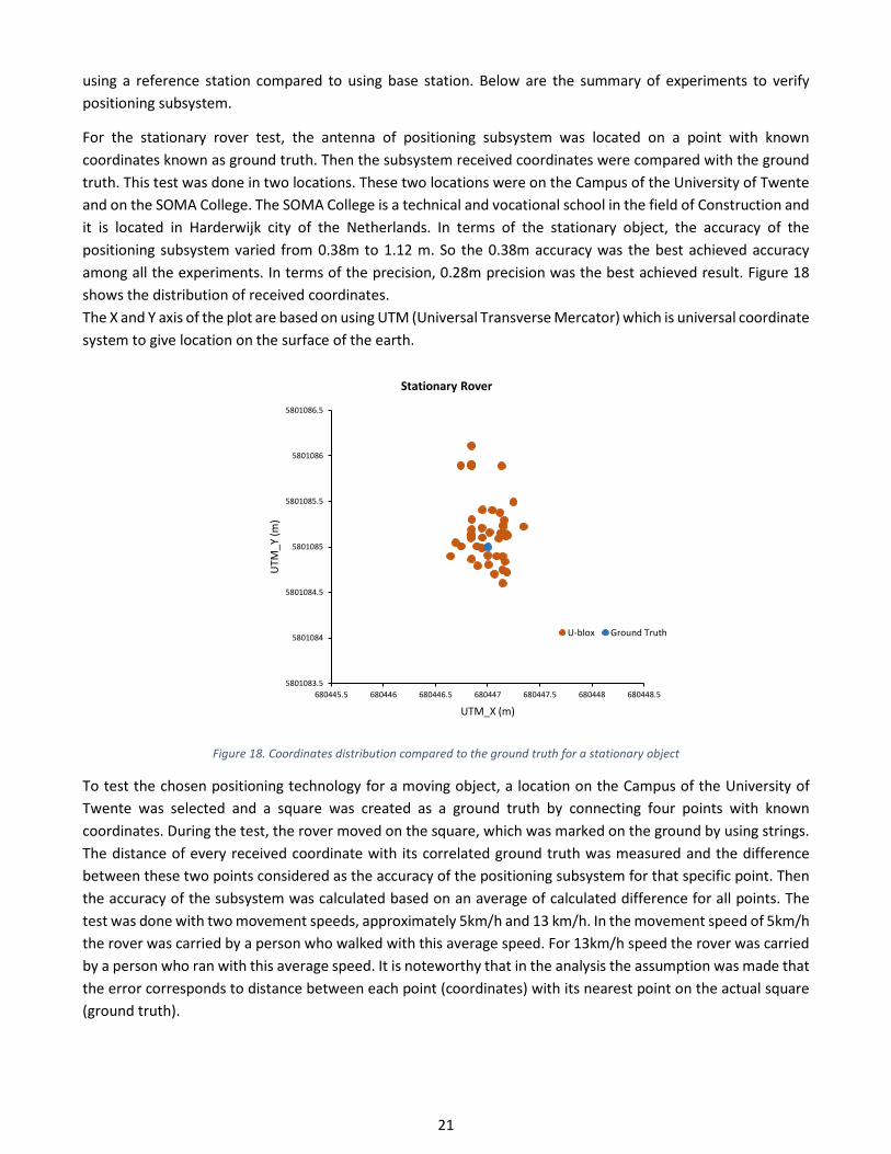
21
using a reference station compared to using base station. Below are the summary of experiments to verify positioning subsystem.
For the stationary rover test, the antenna of positioning subsystem was located on a point with known coordinates known as ground truth. Then the subsystem received coordinates were compared with the ground truth. This test was done in two locations. These two locations were on the Campus of the University of Twente and on the SOMA College. The SOMA College is a technical and vocational school in the field of Construction and it is located in Harderwijk city of the Netherlands. In terms of the stationary object, the accuracy of the positioning subsystem varied from 0.38m to 1.12 m. So the 0.38m accuracy was the best achieved accuracy among all the experiments. In terms of the precision, 0.28m precision was the best achieved result. Figure 18 shows the distribution of received coordinates. The X and Y axis of the plot are based on using UTM (Universal Transverse Mercator) which is universal coordinate system to give location on the surface of the earth.
Figure 18. Coordinates distribution compared to the ground truth for a stationary object
To test the chosen positioning technology for a moving object, a location on the Campus of the University of Twente was selected and a square was created as a ground truth by connecting four points with known coordinates. During the test, the rover moved on the square, which was marked on the ground by using strings. The distance of every received coordinate with its correlated ground truth was measured and the difference between these two points considered as the accuracy of the positioning subsystem for that specific point. Then the accuracy of the subsystem was calculated based on an average of calculated difference for all points. The test was done with two movement speeds, approximately 5km/h and 13 km/h. In the movement speed of 5km/h the rover was carried by a person who walked with this average speed. For 13km/h speed the rover was carried by a person who ran with this average speed. It is noteworthy that in the analysis the assumption was made that the error corresponds to distance between each point (coordinates) with its nearest point on the actual square (ground truth).
5801083.5
5801084
5801084.5
5801085
5801085.5
5801086
5801086.5
680445.5 680446 680446.5 680447 680447.5 680448 680448.5
UTM
_Y (m
)
UTM_X (m)
Stationary Rover
U-blox Ground Truth

22
Figure 19. Positioning experiment location on the University Campus
Figure 20 shows the distribution of the received coordinates by the rover (U-blox, orange) compared to ground truth (blue) in an experiment with two different rover movement speed.
Figure 20. Coordinates distribution compared to the ground truth at 5km/h and 13km/h rover movement speed
All the positioning subsystem experiments can be divided in four categories. These categories are: Test with moving speed of 5km/h by using NETPOS reference stations, Test with moving speed of 13km/h by using NETPOS reference stations, Test with moving speed of 5km/h by using local base station and test with moving speed of 13km/h by using local base station. During the test of the positioning subsystem for these four categories, in addition to the accuracy and precision the update rate of the subsystem also was measured. The update rate is the time interval of the received coordinates. To summarize all the result the average achieved update rate, accuracy and precision for each category is shown in Figure 21.
5790090
5790095
5790100
5790105
5790110
5790115
353375 353380 353385 353390 353395 353400
UTM
_Y(m
)
UTM_X(m)
Rover movement at 13km/h speed
5790090
5790095
5790100
5790105
5790110
5790115
353375 353380 353385 353390 353395 353400
UTM
_Y(m
)
UTM_X(m)
Rover movement at 5km/h speed
Ground Tru
Rover+NETPO
Ground Truth
Rover+NETPOS

23
Figure 21. Radar chart of positioning experiment results
As shown in Figure 21, as a result of the experiments, the average accuracy of the received coordinates varied from 0.5m to 1.57m. The average precision range was from 0.23 to 1.49 meter. Also, the average update rate varied from 1 – 3 seconds. Based on the results , the better result in terms of accuracy, precision and update rate were achieved when using NETPOS reference stations.
The best achieved accuracy and precision in all the experiments is shown in Table 2. These results are based on different moving speed of rover and they were achieved when NETPOS Service was used as reference station.
Table 2. The best achieved accuracy and precision in positioning subsystem test at 5 and 13km/h rover movement speed Rover movement speed Accuracy Precision 5 km/h 0.78 m 0.23 m 13 km/h 0.5 m 0.47 m
7.2 Safety system prototype experiments After developing the prototype of the geo-fencing based safety system it was validated in experiments to measure the reliability of the safety system. The safety system is reliable if not only it generates the alarm when there is a damage risk, but also the excavation equipment operator should be alerted at a right location and within a proper time period. If the safety system generates alarm but with too much latency or when the excavation equipment is very close or very far from the high-pressure pipeline, it is not an acceptable alarm. The valuable alarm is an alarm that is true and accurate, but on time to provide enough time for the user to react to the alarm. The procedure of the experiments to measure the reliability of the system was such that an excavation equipment which was equipped with geo-fencing based safety system went toward a pipeline and it was checked that whether or not the safety system generates alarm when the excavation equipment is closer than defined buffer to the high-pressure pipeline. Among all the experiments that were done it was counted that how many times the safety system generates the alarm on a proper distance and time.

24
The functionality of the safety system depends on functionality of subsystems. The functionality of the geo-fence subsystem is based on calculation, but the functionality of the positioning subsystem can be affected by external factors such as environmental factors. Since the positioning accuracy of less than a meter is required, ± 1.00 meter deviation was considered for the buffer size. On the other hand, based on experiments it was identified that the stability of positioning subsystem to achieve the fix position of an object is less than 2 minutes at latest. When the positioning subsystem loses the coordinates of the object, it takes less than 2 minutes to get the fix position of the object a gain. So, in the prototype validation procedure, 4-6 meter buffer size and 2 minutes time period were used as proper distance and time to evaluate the generated alarm. If the alarm was generated in less than 2 minutes and within 4-6 meters of high-pressure pipelines it was considered as an acceptable alarm, otherwise the generated alarm was considered as non-acceptable alarm (false alarm). The prototype validation procedure of the safety system is summarized in decision tree shown in Figure 22.
Excavate in Safe zone
Alarm Generated?False Positive
excavate in Risk Zone
Alarm Generated?
True Positive
False Negative
Yes No
No Yes
Alarm in less than 2 minute?
Alarm in 4 – 6 m Close to pipe?
Yes
False Negative
False Negative
No
No Yes
Move to Risk Zone
Evaluate Alarm
Evaluate Alarm
Figure 22. Decision tree to validate generated alarms by the safety system prototype
The reliability of the prototype was measured based on comparing the number of acceptable generated alarms to the number of all experiments. In this section, the final result of the validation after complete development of the safety system is discussed. The explanation of all other experiments are in appendix 1. The reliability measurement experiments were done in 4 different locations on the Campus of the University of Twente and its surrounding region. The coordinates of a fictitious high-pressure pipelines were stored on the safety system data base. For each location the experiment was repeated for 5 times. So in total the prototype of the geo-fencing based safety system was tested for 20 times. In 17 experiments out of 20, the safety system generated alarm in proper distance from the pipeline (4-6 meter) and in proper time ( less than 2 minutes). In 2 out of 20 experiments, the safety system generated the alarm but when the excavation equipment was in 3 meter distance from the pipeline. So, these two alarms were considered as non-acceptable alarm. In 1 out of 20 experiments, the safety system generated no alarm at all.

25
Table 3. Result of system prototype reliability measurement
Accepted alarms
Alarm with latency No Alarm
Number of Generated Alarms 17 2 1
Percentage compared to total number of experiments (accepted alarms/total number of experiments)*100 85% 10% 5%
Reliability 85%
To summarize, the reliability of the geo-fencing based safety system was 85% during the validation experiments. In the 10% of the experiments the safety system generated alarm but with latency. Although this late alarm could still be preventive for the third party to cause damages to the high-pressure pipelines, it was considered as non-acceptable alarm because it was not generated in acceptable range of distance and time.

26
8 System Protocols Similar to any other systems, having aimed benefits from using geo-fencing based safety system requires following usage protocols. These protocols consist of the protocols that should be followed in order to use the safety system properly and in order to import current and future high-pressure pipelines data to the system.
8.1 Input data protocol For the current state of the geo-fencing based safety system, the high-pressure pipelines data of Zebra Company and high-pressure pipelines of Gasunie in Enschede region were used. Although, the high-pressure pipelines data of different high-pressure pipelines owners are in shape file, they have different structures. To tailor the safety system with every each of the high-pressure pipelines data, some adjustments in the geo-fence subsystem is required. The safety system is capable of being tailored with other high-pressure pipelines owners data structures. However, to do that, pre-processing of data is required. Since the safety system is supposed to be a plug and play, it is not possible to adjust the geo-fence subsystem every time before using it, based on the input data structure. So, one data structure should be chosen as an input structure and all the input data be imported to the safety system with this structure. The safety system designed such that to import the high-pressure pipelines data to the system the following protocol should be followed:
1. The data of high-pressure pipelines location should be in ‘.shp’ format. In addition to ‘.shp’ file, a complete shape file consists of ‘.dbf’, ‘.prj’ and ‘.shx’ files.
2. The whole high-pressure pipelines should be comprised of multi segments, which known as ‘Multilinestring’ in terms of shape formatted data.
3. Each multi-segment consists of segments (known as Linestring). 4. Each segment consists of points (known as node). The shape file should have the coordinates of these
points. If the data structure is not as abovementioned structure, the preprocessing is required to make this structure. It is also possible to adjust the script of the geo-fence subsystem and make it operable with different data structure. As a future work it is possible to improve the geo-fence subsystem to make it operable with different data structure.
Figure 23. Layers of data in a high-pressure pipelines location file
Multisegment (Multilinestring)
Segment (Linestring) Point (Node)
Multisegment (Multilinestring)
Segment (Linestring)
Point (Node)

27
8.2 Safety system use protocol This section explains the procedure of using the geo-fencing based safety system. Although the safety system is a plug and play system and user does not need to put an extra effort, doing some controls is helpful to prevent any problem in the safety system functionality caused by technical or hardware-related issues. Since the safety system does not have any graphical user interface, it should be possible to check if the safety system is functioning or not. It is worth mentioning that the safety system itself is placed inside the excavation equipment cabin but the positioning antenna of the safety system should be placed in a location with a clear line of sight. It should be placed on the roof of the excavation equipment cabin but without direct contact with the metal of the cabin roof. After starting up the system, following controls should be made to ensure that the safety system in functioning properly:
1. Check if the blue light on U-blox unit is on.
Figure 24. The blue light on the U-blox unit
2. When internet dongle which is attached to Raspberry Pi is trying to connect to the internet, a blinking green light and then blinking blue light can be seen on dongle’s lump. When it is connected to the internet the light changes to constant blue.
Figure 25. The constant blue light on internet dongle that shows the internet connectivity
So, be sure that the lump on internet dongle is constant blue. Otherwise it is not connected to the internet and no data from NETPOS is receiving. Consequently the positioning subsystem does not work properly.
3. The geo-fence platform works based on an auto run Python script. The system has been designed as such when the code has been started the system generates a voice by saying ‘Processing started’. So if the safety system does not generates the mentioned voice, the user should suspect that something is wrong with the safety system.
4. The safety system will generate the second voice when it gets the coordinates of excavation equipment location. At this time the user hears ‘Positon achieved’ voice. So after turning the safety system on, just be sure that you hear two ‘Processing started’ and ‘Position Achieved’ voices. First one indicates that the python code is running. The second one indicates that the coordinates of excavation equipment position have been received by positioning subsystem.
After doing all these controls, you can be sure that the safety system is functioning well.

28
9 System Comparison, Limitations and Impact 9.1 System Comparison The aim of developing the geo-fencing based safety system of this project is to help reduce the third party caused excavation damages to high-pressure pipelines. To address this target group it is essential to make the safety system understandable and affordable for them. Although there are several similar technologies, not all of them can satisfy the requirements mentioned in section 4.2. To analyze the existing probably similar technologies, an investigation was done to compare the developed safety system of this project with the other similar systems. During the investigation it was tried to find the similar technologies as many as possible. Also searching to find the similar systems was not restricted only to the Netherlands but it was tried to cover all the countries. The rest of the section explains the found results.
Since during the investigation no exact similar safety system to the geo-fencing based safety system could be found, the focus was not only on finding similar systems but also many systems that were not specifically for the asset safety but were developed based on geo-fencing and positioning concept were investigated. The criteria to make a comparison were the accuracy of positioning system for a stationary and moving object, the price of the product, the system interface, being an open-source or a closed package and the alarming technology.
Since these systems are mostly commercial products, not all the required information to have a systematic comparison could be retrieved from their company’s website. So, these companies were contacted to collect required information. Among 13 contacted companies only 4 of them were responsive. So, the developed safety system of this project which is a geo-fencing based safety system was compared with 4 products. These product are:
- RacTrac which is fleet management system that works based on GPS tracking, - EasyTracGPS which is a fleet management system, - 12Trace is a geo-fencing based fleet management system, - Advanced Navigation is a positioning system.
It should be mentioned that these system are not specifically a safety system for high-pressure pipelines, but they are asset management and positioning systems. The comparison is explained below to mention the advantages and disadvantages of these systems.
Table 4. System comparison
RacTrac EasyTracGPS
12Trace
Advanced Navigation
The geo-fencing based safety system (developed in this project)
System Application Fleet Management
system based on GPS tracking
Fleet Management system based on
GPS tracking
Goe-fencing based fleet
management
Positioning System
Safety system
Positioning Accuracy (m) 3 3 5 0.01 1
Price (€) 250 250 Monthly subscription fee
2000 200
Open Source No No No Yes User Interface Graphical Graphical Graphical Audible Alarming technology Various features Various features Various features SMS/Email

29
It is worth mentioning that not all the presented results could be retrieved from the website of product’s companies or other online references. So the presented results were mostly collected via email. To summarize the comparison, although the investigated commercial products could provide lots of additional features such as graphical interface, indicating the orientation and heading the vehicle, cloud-based data transmission and a few other features, none of the found products could provide required positioning accuracy within the defined range of price.
9.2 System Constraints The current state of developed safety system is a low cost but sufficiently accurate safety system. However it has some limitations:
First. One of the limitation is using the NETPOS service in positioning. The NETPOS service was accessible for this project but it is not publicly available to use. Regarding that, using the safety system in construction sites, needs access of high-pressure pipelines owners to the NETPOS in order to use this safety system. However, having no access to the NETPOS service is not a failure for the safety system as the NETPOS service can be replaced with local base stations. But it might lower the level of accuracy. To avoid dependency on NETPOS and to avoid reduction of accuracy, a solution can be to ask the high-pressure pipelines owners to create their-own network of reference stations along their high-pressure pipelines. Considering the 20 km distance between reference stations, the number of required reference stations and their cost should be investigated to see if stablishing reference stations along the high-pressure pipelines is cost beneficial or not. Second. Another limitation for the safety system is the dependency of the safety system on the internet connection. In the developed safety system to get the positioning correction messages from the NETPOS and to send alarm via SMS or Email to high-pressure pipelines owners, an internet connection is required. Considering that the high-pressure pipelines locations can be in a remote area, there is a risk of having no internet network coverage. As a consequence, it affects the effectiveness of the system. However, losing the internet network is not a failure for the system because the positioning subsystem can still work based on only receiving the positioning data from the satellites without correction messages. Also, without having SMS system, still the excavation equipment operator which is the main target group of the safety system is alerted. Nevertheless, if the positioning subsystem works in a single mode it will reduce the accuracy of the safety system. It should be mentioned that, although in the current state of the system an online platform is used to send SMS alarms, it can be replaced with another technology that works based on telecommunication platform and does not need to have internet to send SMS. Yet to send alarm via Email having internet is indispensable. Third. The safety system uses two layers of alarm and the speed check feature to filter false alarms in case of the excavation equipment is just passing by the high-pressure pipelines location and it is not carrying out an excavation operation. However, it can happen that the excavation equipment is staying at risk zone, with no move while it is not doing an excavation operation but it has just stopped there for any reason. Although it is out of the scope of this project to consider the scenario that the excavation equipment stays at a place with both engine and safety system on while doing no activity, it should be considered as a possible scenario that can cause false alarm. Avoiding this kind of false alarms is a bit complicated. Adding pose estimation feature to the system can overcome this problem. In the pose estimation process, three sensors are connected to the boom, stick and the bucket of the excavator. Based on the distance and angel of these three sensors the safety system can identify that if the excavator is doing an excavation operation or not. However adding the pose estimation feature to the safety system increases the cost and the complexity of the safety system.

30
9.3 Safety system impact Although there are several existing systems and applications that work based on geo-fencing concept, to the best of author’s knowledge, none of them are specific for the underground asset safety with the level of price and accuracy that geo-fencing based safety system provides for the user. Considering the concern of high-pressure pipelines industry which is avoiding the excavation damages to the high-pressure pipelines that are caused by third parties, the geo-fencing based safety system is a system with a price that is affordable for third parties and a good level of reliability. Furthermore, the geo-fencing based safety system is a plug and play safety system that causes no intrusion to the excavation operation. Also, the use of safety system requires no preparatory work and imposes no extra work on excavation equipment operator. Profiting the safety benefits of using geo-fencing based safety system without suffering from its cost, its intrusion to the excavation operation and its imposed extra work, can motivate the third parties and the contractors to use the geo-fencing based safety system on their excavation equipment. Some features of the geo-fencing based safety system makes it distinguished from other similar systems in terms of system development. The features are:
a. The geo-fencing based safety system has been designed such that it generates two layers of alarms. Furthermore to check if the excavation equipment is on excavation condition or not the speed check feature was added. Generating two layers of alarm and having the speed check feature can have a great impact to reduce the number of false alarms that are the most annoying issue among the safety systems.
b. In the most of the systems that work based on geo-fencing concept, the geo-fence is defined around the aimed object but in geo-fencing based safety system, the geo-fence is created around the excavation equipment and not the high-pressure pipelines. This makes the data processing and collision identification process faster. another design decision to make the processing faster, is that the geo-fencing based safety system is designed such that it first identifies the location of the excavation equipment and based on the excavation equipment location it checks that which of the high-pressure pipelines are close to the excavation equipment location and there is potential risk for them to be damaged by the excavation equipment. Then the collision identification process is done only for those high-pressure pipelines. This makes the data processing much faster.
c. Another advantage of the geo-fencing based safety system in terms of system development impact is that the developed safety system works based on using open source applications and software. This makes the future development of the safety system more possible.

31
10 Conclusion The third parties are the main cause of the high-pressure pipelines incidents and a safety system that can reduce the incidents caused by this target group is demanded by the high-pressure pipelines owners association (VELIN). The safety system can motivate the third parties to use that if:
• It is affordable by the third parties, • It is designed specifically for high-pressure pipelines, • It has a simple functionality and understandable user-interface, • And, it is not intrusive for the excavation operation,
There are several technologies that use the concept of geo-fencing for different applications. Even a few cases of them can be used for the underground utility safety. However, these systems do not consider all the criteria such as low cost and simplicity for using the system to reduce the third party-caused incidents are considered. The developed safety system specifically addresses the defined requirements to motivate third parties to use the safety system. The main advantage of the safety system compared to other existing ones is having the combination of very low cost and a very good accuracy.
The geo-fencing based safety system tracks excavation equipment and creates a virtual buffer (known as geo-fence) around them. It checks in real time any collision between the buffer and the high-pressure pipelines which their location data has been imported to the safety system. If the safety system identifies any collision it generates the first layer of alarm to alert excavation equipment operator about a potential risk and if the risk stays valid for 30 seconds, the safety system generates the second alarm and alerts high-pressure pipelines owners via SMS and Email.
The geo-fencing based safety system consists of three subsystems which are the positioning subsystem, geo-fence subsystem and alarm subsystem. The positioning subsystem uses the combination of U-blox positioning unit with RTKLIB software, NETPOS reference stations, a Python script and a Raspberry Pi as a processor. In the geo-fence subsystem a Raspberry Pi is processing hardware and the Python Scripting Language as a processing software. The data of high-pressure pipelines location is a vital component of this subsystem that are imported with .shp format to the data base of the geo-fence subsystem. Alarm subsystem a part from using the Python Scripting Language to communicate with high-pressure pipelines owners, it uses an audio speaker to play different alarms. An internet dongle that uses a telecommunication Sim Card is used in both positioning and alarm subsystem to provide internet connection for these subsystems.
The result of system validation shows that the safety system can meet the defined requirements and is reliable to be used to avoid excavation-caused incidents. The validation of the positioning subsystem shows that the positioning subsystem can provide a sub meter accuracy. Having this level of accuracy has a direct impact on the functionality and reliability of the safety system. The positioning subsystem is a main pillar to make the safety system able to meet the requirements. However, the safety system is not restricted to use only the positioning technology that was used in this project. During the system development other positioning technologies also were tried but the chosen positioning technology had a better result. So, the safety system is capable to apply other positioning technologies, of course with some adjustments. This possibility opens the room for the safety system to apply more developed positioning technologies in the future. This can make the safety system more durable. Despite the all aforementioned advantages of the safety system, it has some constraints. These constraints are more related to prototype of the safety system and are solvable. One of the constraints is dependency of the safety system on internet. Although the safety system functions even without having the internet connection, absence of internet connection compromises the reliability of the safety system. Furthermore, the safety system

32
uses NETPOS service in positioning and the NETPOS service is not publicly available at the moment. So, using the NETPOS service to enhance the reliability of the system can also be considered as a constraint. However it is possible that high-pressure pipelines owners create their own reference stations which should be investigated in terms of cost benefits and implementation. In summary, despite the constraints, the developed safety system can help reduce the number of third party -caused excavation damages to the high-pressure pipelines. Although, the developed safety system is aimed for reducing the number of high-pressure pipelines incidents, It is not claimed that the proposed geo-fencing based safety system is a replacement for KLIC-melding service. It is a complementary system to the KLIC-melding service. Based on the output of workshop, symposiums and the presentations of the safety system in different occasions with presence of people from high-pressure pipelines industry, the safety system seems helpful to reduce the number of incidents specifically when the third party does not ask for the high-pressure pipelines location data from the KLIC information center.

33
11 Recommendations and Future work This chapter consists of recommendations and possibilities for further work on high-pressure pipelines safety.
11.1 Recommendation Although the developed safety system can help reduce the number of third-party caused excavation damages to high-pressure pipelines, to reduce the number of incidents to zero, more initiatives are required. These initiatives can be done in different streams:
1. The geo-fencing based safety system addresses one of the dominant causes of high-pressure pipelines damages which are third parties. However, the VELIN as the owner of the high-pressure pipelines should take initiative to develop other safety systems that can address all different causes of high-pressure pipelines damages. Examples of such a systems is a safety system that can avoid damages to the high-pressure pipelines caused by hand-held excavation equipment. The safety system development not only should be done for monitoring safety systems but also for detection technologies, as shown in Figure 26:
Figure 26. Three work packages for development of a multi layered safety system
2. The geo-fencing based safety system has been presented several times during different workshops, symposiums and meetings, and the output of these presentations have been applied to improve its performance. However it would be better that the VELIN implements the safety system first in a smaller scale as a pilot. During the implementation in smaller scale, the safety system is being tested on different work conditions and the interaction of the user with the safety system is more investigated. Also it helps to more investigate the causes of false alarm generation. Based on the pilot implementation and feedback, safety system can be improved to be used in larger scales.
3. The implementation of the safety system, requires to persuade contractors and machine owners to mount the safety system on their equipment. But it is difficult to control every each of the excavation equipment to check if it is equipped with geo-fencing based safety system or not. The recommended way to implement the safety system on all the equipment is that the manufactures or rental firms accept to add the safety system to their excavation equipment as a safety option. This should be done via the Ministry of Infrastructure and Water Management.
4. The developed safety system is a monitoring safety system that uses the high-pressure pipelines data of KLIC-melding service as reference. However it is not a replacement for KLIC-melding service or other detection and monitoring technologies. Nevertheless, the accuracy of data has a direct impact on reliability of the safety system. Based on expert’s opinion, there is an uncertainty about the exact accuracy of high-pressure pipelines data. It was not in the scope of this PDEng project to check the accuracy of high-pressure pipelines data, but having a platform to use practical experiences to check and

34
correct the accuracy of high-pressure pipelines data can help also to increase the reliability of the geo-fencing based safety system. This platform can be developed by Kadaster and this organization will benefit from the platform in order to increase the accuracy of the asset location data.
5. During the PDEng project and developing the geo-fencing based safety system, I tried to involve the stakeholders and the end-user of the product to the project to use their opinion and feedback in safety system design. However, the socio-technical aspect of the product and the interaction of end-user with the safety system can be more investigated during the safety system pilot implementation. The end-user feedback about reliability, user-interface and the safety system’s intrusiveness to the excavation operation can help improve the geo-fencing based safety system. It also helps in large-scale implementation of the safety system. The development team with coordination of the VELIN can do a research work to investigate the socio-technical aspects of the geo-fencing based safety system.
6. To make the implementation of the safety system durable and sustainable, the high-pressure pipelines location data of the safety system should be updated regularly. Also the safety system should be upgraded in line with technology development. As an example the positioning technology that is used in the current state of the developed safety system can be replaced by another future positioning technology in case it has better accuracy and lower cost. A collaboration of VELIN with a provider Company or Companies helps provide support for the safety system in terms of data update, system upgrade and also to commercialize the safety system with even lower price compared to the current cost. Because producing the safety system in larger scales can reduce casing, branding and other additional cost and makes the safety system cheaper.
11.2 Future possibilities There are several possibilities to improve the safety system when it is aimed to be used in industry. These possibilities were investigated but not applied in this PDEng project.
Geo-fence buffer size: In this PDEng project the buffer size was considered for a situation that matches with the most cases of the excavation work but to make it compatible with all the possible conditions, different kind of buffer size should be defined. The size of the buffer can differ based on:
• Different excavation equipment • Different speed of excavation work • Different kind of excavation work
Adding different buffer sizes to the safety system is considered as a short-term possibility.
Pose estimation To increase the reliability of the safety system and to reduce the number of false alarms it is feasible to add motion tracking (pose estimation) subsystem to the safety system. With positioning only the location of the excavation equipment can be known and additional process is needed to check if the excavation equipment which is in the risk zone is doing the excavation operation or it only passes by. Using some sensors such as Inertial Measurement Unit (IMU) helps identify the pose of boom, stick and bucket of the excavator to check the excavator is really carries out the excavation operation. Despite its advantages the main disadvantage of adding the pose estimation feature to the safety system is the extra cost and complexity that it causes. However, the pose estimation development is an ongoing project in the Department of Construction Management and Engineering in the University of Twente. So it can be considered as a feasible and short-term possibility.

35
Data update The safety system prototype has been developed and tested based on high-pressure pipelines data of Zebra and Gasunie Companies. But the geo-fencing based safety system is supposed to use the high-pressure pipelines location information of Kadaster. These data need to be updated in specific time periods, because of installation of new high-pressure pipelines or any other changes on the high-pressure pipelines location. This specific time period is determined based on investigation of the historical experiences of high-pressure pipelines location change. In the prototype of the safety system, database of the safety system that contains the high-pressure pipelines location data is updated manually. So, in case of new high-pressure pipelines installation, the location information of the installed high-pressure pipelines should be imported to the safety system manually. Thinking of future possibilities, since the device has an internet connection, it is possible to make an online data update in specific time periods. However to update high-pressure pipelines data online the security issues should be considered. If the data owner agrees that public access to the high-pressure pipelines data causes no issue in terms of security and data policy, online update of high-pressure pipelines location information is feasible in short term.

36
12 References
Anspach, J. (2016). Vups pilot project final report.
Asadollahi, S., olde Scholtenhuis, L., Vahdatikhaki, F., & Doree, A. (2018). Geofencing-based safety system for high-pressure pipelines. In CROW Infradagen.
Asadollahi, S., olde Scholtenhuis, L., Vahdatikhaki, F., & Dorée, A. (2017). Review of Detection and Monitoring Systems for Buried High Pressure Pipelines.
CONCAWE. (2013). European downstream oil industry safety performance. CONCAWE Reports.
Emlid. (2018). Retrieved from https://docs.emlid.com/
European Gas Incidents Group. (2015). 9th Report of the European Gas Pipeline Incident Data Group.
Fotiou, A., Pikridas, C., Bimpisidou, A. (2009). DGPS and RTK positioning using Hermes NTRIP Caster.
Gasunie. (2015). Annual Report 2015.
Muggleton, J., Rustighi, E. (2013). Recent developments in vibro-acoustic techniques to locate buried infrastructure. (2013). Geotechnique Letters
Harmsen, D. M., & Emous, A. C. van. (2006). Reducing Digging Incidents Using Risk Management.
Jeong, H. S., Arboleda, C. A., Abraham, D. M., Halpin, D. W., & Bernold, L. E. (2003). Imaging and Locating Buried Utilities.
Subsurface Surveys Associates. (2015). Geophysical Methods & Applications.
Kadaster. (2016). Productplan KLIC 2016-2018.
Jauregui, J. M. (2017). Design Process Unit (DPU).
Kadaster. (2018). Retrieved from https://zakelijk.kadaster.nl/netpos
Koppens, B. (2013). Dutch one call system.
Lenz, E. (2004). Networked Transport of RTCM via Internet Protocol (NTRIP) – Application and Benefit in Modern Surveying Systems.
Capstick, D. (2007). 3D: Modelling, Augmented Reality and applications applications.
Leon olde Scholtenhuis. (2017). ZoARG | ReDUCE. Retrieved from https://www.utwente.nl/en/et/cme/research/research-themes/zoarg/
Okon, U. E. (2016). Utilization of the Internet in Pipeline Protection against Vandalism.
OSYS technology limited. (2009). Next Generation GPR Technology.
Rogers, C. D. F., Chapman, D. N., Royal, A. C. D., Metje, N., & Atkins, P. R. (2012). Mapping Sub-Surface Streetscapes.
RTKLIB. (2018).
Sterling, R. L., Allouche, E. N., Anspach, J., Matthews, J., Berchmans, J., & Simicevic, J. (2011). Development of the Selection Assistant for Utility Locating Technologies.
Subsurface Surveys Associates. (2015). Geophysical Methods & Applications.
UTwente - Aspari. (2015). ASPARI. Retrieved from http://www.aspari.nl/

37
UTwente - ZoARG. (2017). ZoARG Symposium. Retrieved from http://www.zoarg.com/symposium/
VELIN. (2017). Retrieved from http://www.velin.nl/
Wang, Q. (2004). Research on Long-Distance Monitoring of Oil Theft in Buried Pipeline.
Wieringa, R. (2014). Design science methodology. the 32nd ACM/IEEE International Conference.

38
13 Appendices 13.1 Appendix 1 _ System verification experiments During the development of geo-fencing based safety system several experiments were done. Achieved result in every each of experiments were used to improve the functionality of the safety system. The main improvement activities based on the result of each experiment were modifying the Python script and configuration of the positioning subsystem. Below are the summarized explanation of these experiments:
Prototype test in a hypothetical condition To do the experiments in hypothetical condition, firstly, a square with strings was placed on the test location to replicate the geo-fence. As mentioned before in the early stage of the safety system development the geo-fence was created around the high-pressure pipeline. In this test, the safety system was mounted on a remotely-controlled scaled excavation equipment and a hypothetical pipeline used.
Figure 27. Test of the safety system prototype in hypothetical condition
The experiment repeated for 3 times. In all 3 times the alarm was generated but only one time it was within ± 1.00 meter from the defined threshold which is considered as True Positive. In the other 2 experiments the alarm generated when the excavation equipment was in the buffer more than 1 meter so it is considered as a false negative alarm. Based on the experiment it was concluded that the design improvement is required. This improvement was about configuration of positioning subsystem and modifying the Python Script.
Prototype test in the actual high-pressure pipeline location The later series of experiments was testing the prototype at a location with actual high-pressure pipeline. At this state, to make the collision identification process faster, the design team decided to create the buffer (geo-fence) around the excavation equipment instead of creating buffer around all the high-pressure pipelines. The tests were done at a location in Enschede region, where the high-pressure pipeline of the Gasunie Company is located. For these tests since using an excavation equipment was not possible, the safety system was mounted on a personal regular car.
Figure 28. Test of the safety system prototype in an actual high-pressure pipeline location

39
This experiment repeated several times in different weather conditions and in summary 60% of the experiments led to getting True positive alarm. Which meant that still improvement is required.
Demo test at SOMA College A demo test of the safety system prototype was done at SOMA college which is located in the Harderwijk city of the Netherlands. The college is aimed for educating people about constructing activity. So, the excavation equipment was accessible. Since there is no actual high-pressure pipeline at the SOMA, a hypothetical high-pressure pipeline was located and test was done by using data of this high-pressure pipeline. The safety system functioned well during the test and when the excavation equipment located close to the high-pressure pipeline it generated the first alarm and after 30 seconds that the excavation equipment remained at the risk zone the second alarm was generated. It also sent alarm messages to one of people there as a representative of high-pressure pipeline owner.
Figure 29. System prototype demo test in an actual excavation condition at SOMA College with audience from VELIN
13.2 Appendix 2_Work shop Each design process has two main systems: One system is the technical system which is the collection of technical elements such as hardware (artifact itself) and software (programs and operating systems and specialized codes). But this technical system should be implemented in the society. So it has to have an interaction with a social system. This social system consists of elements, like people, companies, organizations that can influence the design or be influenced by the design. These people, companies or organizations are the stakeholders of the design. During the implementation of the technology into the social systems some issues happen which cause less commitment of the stakeholders. To understand the issue in advance and acquire the commitment of the stakeholders, it is required to involve them during the system development. Presenting the concept, its aim, its objectives, its design and functionality helps to make the stakeholders involved during the system development. Holding workshops is a way that provides possibility to present the project to stakeholders. The geo-fencing based safety system was presented to different stakeholders during the project. One of the main presentations was the workshop of geo-fencing based safety system during the ZoARG Symposium which is explained below:

40
ZoARG Symposium The Construction Management and Engineering Department in the University of Twente is active in different domains in Construction industry. Aspari and ZoARG are two main streams of these domains. In Aspari domain, the goal is to strengthen the professionalism in Asphalt road construction (UTwente - Aspari, 2015). In ZoARG domain, the focus is on reducing damage to utilities and careful excavation. ZoARG is a collaboration between the utility sector and the University of Twente (UTwente - ZoARG, 2017). The goal of the ZoARG is to enhance the awareness of the excavation supply-chain regarding careful excavation and it tries to involve organizations in initiatives to reduce the excavation damage to the underground utilities. Examples of the ZoARG current projects in the Construction Management and Engineering Department are improving underground utility data, improving decision support system for selecting test trenches location, training simulators for excavation equipment operators, developing high-pressure pipeline safety systems and educating people to use ground penetrating radar for damage avoidance (Leon olde Scholtenhuis, 2017).
University of Twente has organized two ZoARG Symposium. First one was held in 2013 and the second ZoARG Symposium was organized and held on October 19, 2017. The goal of the Symposium was to inform utility sectors of the work done by the Universtiy Twente within the ZoARG program. During the ZoARG Symposium several workshops were held by the staff and PDEng trainees of the Construction Management and Engineering Department. PDEng trainees and staff presented their projects and their so-far work for the Symposium participants. People from the different companies and organizations were invited for the Symposium. Almost 44 companies or organization accepted to attend to the Symposium. Representatives of some of these companies participated in geo-fencing based safety system workshop. Example of these organization or companies are NAM (Nederlandse Aardolie Maatschappij), TerraCarta, Kadaster and HZC (Het Zwarte Corp).
Geo-fencing project workshop Infographic of the project, the presentation slides and the needed equipment for the workshop had been prepared beforehand. The plan was having a short introduction at first to explain the session outline and the goal of the workshop. Then presenting the project, followed by a question and answer session to let the participants ask their questions. Finally asking some questions from the utility sector to help me in defining design requirement from the practical point of view. Table 5 shows the plan of the workshop.
Table 5. Plan of Geo-fencing project workshop # Duration (min) Detail 1 5 Introduction
- Workshop goal - Workshop outline
2 20 Presentation - Present VELIN project - Present Geo-fencing project - Present project progress and so far result
3 10 Question and Answer
4 10 Discussion - Determine design main criteria - Define design requirement
5 5 Engagement in PDEng - Ask utility sector to be involved in the project - Ask for high-pressure pipeline data
41
Workshop Problems Because of presenting two projects, one the research work about the “Investigation of underground utility detection and monitoring technologies” and the other the “Geo-fencing based safety system”, the presentation part lasted more than planned time and consequently less time was left for the discussion part. I tried to collect the people’s opinion in a written way by asking them to write their priority and thought requirement on the paper, but the discussion were proceeded more verbally.
Workshop Goal I had three goals in planning the workshop. Frist, introducing my project to the utility sector, second, to know the design requirement and main design criteria from the expert and practical point of view which is partly achieved. Third, asking industry people about their motivation for being involved in the project. However because of time shortage the final goal was not achieved.
Workshop Process During the presentation session, firstly I presented the research work which I did before my PDEng about investigation of existing utility detection and monitoring technologies. Then, I followed the presentation with presenting my PDEng project which is about Developing a geo-fencing based safety system. Because of presentation of two projects, the time management did not coincide with the planned schedule. However, the contribution of the participant went well as such they actively participated in Q&A and the discussion sessions. It helped me to achieve the expected workshop output about the design requirement, partly.
Workshop Challenges Time management was a main challenge in the workshop. Presenting two projects in 20 minutes was challenging because I tried to cover all the material. Also, keeping audience motivated during a long presentation was a bit of challenge. Although, I ran overtime during presentations, people were very motivated and excited.
Workshop Output Based on the feedback that I got immediately after the workshop, also received via later emails, I recognized that the project was introduced properly and the most of the workshop participants were interested in topic. The workshop also helped me to better determining the requirement of the project such as the price of the safety system, the buffer size, user interface, etc.

42
13.3 Appendix 3_ PDEng project Timetable In addition to the educational courses, a design project, also, is done in PDEng program. The design project is done for the whole entire two years of PDEng. In addition to the timetable of the PDEng program, another timetable has been provided specifically for the design project which should be followed to finish the design project on time. Figure 30 shows the timetable of the design project.
Figure 30. Timetable of the PDEng project

43
13.4 Appendix 4_ Publications A conference paper was provided related to geo-fencing based safety system. It was for the Infradagen Conference that was held in 2018 and the paper was published. The paper can be found in below link.
https://www.researchgate.net/publication/329150873_Geofencing-based_safety_system_for_high-pressure_pipelines
The project was presented in ZoARG Symposium in October 2017, the Infradagen Conference in July 2018 and the VELIN workshop at SOMA in October 2018.