csrrs in the ground plane stopband characteristics for ... that can be excited by an axial electric...
TRANSCRIPT

Full Terms & Conditions of access and use can be found athttp://www.tandfonline.com/action/journalInformation?journalCode=titr20
Download by: [Indian Institute of Technology Guwahati] Date: 07 February 2016, At: 04:27
IETE Technical Review
ISSN: 0256-4602 (Print) 0974-5971 (Online) Journal homepage: http://www.tandfonline.com/loi/titr20
Stopband Characteristics for Periodic Patterns ofCSRRs in the Ground Plane
Rakhesh Singh Kshetrimayum, Sridhar Kallapudi & S S Karthikeyan
To cite this article: Rakhesh Singh Kshetrimayum, Sridhar Kallapudi & S S Karthikeyan (2007)Stopband Characteristics for Periodic Patterns of CSRRs in the Ground Plane, IETE TechnicalReview, 24:6, 463-474
To link to this article: http://dx.doi.org/10.4103/02564602.10876631
Published online: 01 Sep 2014.
Submit your article to this journal
Article views: 13
View related articles

463
IETE Technical ReviewVol 24, No 6, November-December 2007, pp 463-474
Stopband Characteristics for Periodic Patterns ofCSRRs in the Ground Plane
RAKHESH SINGH KSHETRIMAYUM, SRIDHAR KALLAPUDI AND S S KARTHIKEYAN
Department of Electronics and Communication Engineering,Indian Institute of Technology, Guwahati, Assam 781 039, India.
email: [email protected]
Stopband filters are designed by etching periodic patterns of complementary split ringresonators (CSRRs) in the ground plane of a microstrip line. CSRRs, being sub-wavelengthresonators, their size are much more smaller than the conventional microstrip resonators.As a resonator, it has been observed that a single CSRR in the ground plane has a very highQ factor and gives a very high rejection in the stopband. It has also been observed that theperiod of the CSRR loaded microstrip line can be made as small as lllll/10 of the operatingwavelength thereby extensive size miniaturization is possible. With the increased number ofCSRRs etching and decreased period of the periodic structure loaded with CSRRs in theground plane of the microstrip line, the stop bandwidth increases and side by side therejection level in the mid stopband frequency increases significantly thereby furtherenhancing the stopband filter performance along with the extensive size miniaturization. ACSRR-stub filter has been proposed for harmonic suppression of microstrip filters and it hasbeen used successfully for harmonic suppression of stepped impedance low pass filters.
[5]. In this paper, we will do a detailed investigation ofCSRR based stopband filters: starting with a singleCSRR etching in the ground plane, finding its stopbandcharacteristics, quality factor and after that the effectof number of CSRRs and periodicity on the stopbandfilter performance is investigated. A stub-CSRR filterhas been proposed for harmonic suppression ofmicrostrip filters and it has been applied for harmonicsuppression of stepped impedance low pass filters. Itshows a steeper and increased out-of-the-band filterperformance without compromising the in-band filterperformance.
2. CSRR BASED STOPBAND FILTERS
SRR and CSRR depicted in Fig 1a and 1brespectively are small resonant particles with a highquality factor [6]. CSRR is a complementary structureto SRR. CSRR essentially behaves as an electricdipole that can be excited by an axial electric field.The CSRR behaves as an externally driven parallelLC resonant circuit [7]. The resonant frequency ofthese particles can be tuned with the help of devicedimensions: rext, c and d depicted in Fig 2. In our case,CSRR is formed by etching out the metallic portion inthe shape of SRR in the ground plane of microstripline. Both SRR and CSRR with the same dimensions
1. INTRODUCTION
SIZE miniaturization of microwave filters is of much demand in the today’s rapid changing
communication world. Even though end-coupled bandpass filters and parallel-coupled band pass filters [1]with the half wavelength resonators are prevalent, theyare much larger in size. There exist filters with quarterwavelength resonators. Even these filters also occupya large amount of device area at lower range ofmicrowave frequencies. Many microstrip filter designshave been proposed in the past few decades but thereare rooms for improvements.
Recently, metamaterials [2] are gaining a lot ofinterest to researchers across the globe because suchartificial materials produce –e and –µ electromagneticproperties, which do not occur in naturally occurringelectromagnetic materials. Split Ring Resonators (SRR)and Complementary Split Ring Resonators (CSRRs)also called as Sub Wavelength Resonators [3,4], due totheir size much smaller than the wavelength, are thecomponent particles for such exotic artificial materials.These components for metamaterials can design filterwith improved filter characteristics and sizeminiaturization, preliminary results has been reported in
Paper No 80-A; Copyright © 2007 by the IETE.
Dow
nloa
ded
by [
Indi
an I
nstit
ute
of T
echn
olog
y G
uwah
ati]
at 0
4:27
07
Febr
uary
201
6

464 IETE TECHNICAL REVIEW, Vol 24, No 6, November-December 2007
resonate at the same frequency and their resonantfrequency can be approximately calculated using theclosed form expressions given in [7]. Complementarysplit ring resonators (CSRRs) are used in the groundplane instead of SRRs in the same plane of themicrostrip line to achieve the stop band characteristics.One of the major advantage is that for applications likesuppression of harmonics of a band pass filter/lowpass filters, we can design the band pass filter/lowpass filter in the upper part of the substrate and we
can make such kinds of CSRR structure in the lowerground plane of the substrate thereby there is moredegrees of freedom for designing the filter as well asthe device used for harmonic suppression. Besides,there are no additional requirements in area for thedevice, which is used for harmonic suppression.
3. RESULTS AND DISCUSSION
A CSRR structure is designed to resonate at 8.3GHz of the X-band microwave frequency region. Thedimensions of the CSRR structure chosen for thisfrequency of operation are rext=1.0 mm, c=0.2 mmand d=0.2 mm respectively. The dependence on thedimensions of the CSRR structure on the resonantfrequency is observed as follows: with the increase ofexternal radius (rext), resonant frequency decreasesand with the increase of the ring width (c) and gapwidth (d), resonant frequency increases. The CSRRstructure is placed in the ground plane exactly belowthe center of a microstrip line of width 2.89 mm for aFR4 dielectric substrate of er=4.4 and height (h) 1.6 mmas shown in Fig 3a. Same substrate is used for allother later designs. All the designs are simulated usingZeland IE3D software [8]. The simulation results fora single CSRR etching in the ground plane of a microstripline are shown in Fig 3b.
The results of scattering parameters againstfrequency (GHz) show narrow stop band characteristicsat the fundamental resonant frequency of CSRR at8.3GHz. By placing a single CSRR structure in theground plane, we can obtain a narrow stop band with asignificantly high attenuation level, which is not possiblewith conventional filter designs. It is difficult to achievesuch a good narrowband stopband filter performancewith a single element of conventional filter resonators.Stopband width of the above single CRRR loadedmicrostrip line filter is approximately 150 MHz and ithas a very high quality factor of 12546 at the resonantfrequency of 8.3 GHz. A CSRR has an equivalentcircuit of a shunt LC resonator and its quality factor atthe fundamental resonance can be obtained from theequivalent circuit extracted from its impedance [Z] oradmittance [Y] parameters. Note that the secondstopband width is almost doubled but the fractionalstopband width is still the same and hence we will do adetailed investigation of the first stop band only. Similarkind of stop band filter response is expected for thesecond stop band.
Here our concern is to enhance the stopband filtercharacteristics by increasing the number of CSRRstructures in the ground plane. This is achieved byplacing more CSRRs with the same resonant
(a)
(b)
Fig 1 (a) SRR and (b) CSRR
Fig 2 Structure of the CSRR showing thephysical dimensions
Dow
nloa
ded
by [
Indi
an I
nstit
ute
of T
echn
olog
y G
uwah
ati]
at 0
4:27
07
Febr
uary
201
6

Fig 3 Stopband filter resonator of single CSSR in the ground plane (a) front view ofthe design (b) scattering parameters of the stopband filter
(a)
(b)
frequencies periodically. Such a stopband filter structureis shown in Fig 4a having three CSRR structures inwhich all the CSRRs resonate at the same frequencyof 8.3 GHz. Distance between the centers of any twoadjacent CSRRs also called as period is maintained at3 mm. The simulation results are shown in Fig 4b. Thesimulation results depicted in Fig 4b shows a stop bandat 8.3 GHz with a stop bandwidth of approximately
400 MHz. Comparing Fig 3b and Fig 4b, we canobserve an improvement in the stop bandwidth ofnearly 250 MHz. We can also observe a significantincrease in the rejection levels in the stopband. Atresonant frequency the attenuation level is maintainedat 18 dB for the stopband filter with single CSRR andit is at 38 dB for the stopband filter with three CSRRstructures.
RAKHESH SINGH KSHETRIMAYUM et al : STOPBAND CHARACTERISTICS 465
Dow
nloa
ded
by [
Indi
an I
nstit
ute
of T
echn
olog
y G
uwah
ati]
at 0
4:27
07
Febr
uary
201
6

466 IETE TECHNICAL REVIEW, Vol 24, No 6, November-December 2007
Fig 4 Stopband filter having 3 CSSRs in the ground plane (a) front view of thedesign (b) simulated results
(a)
(b)
The CSRR structures in the ground plane is furtherincreased to seven as shown in Fig 5a and simulatedin the same frequency range of 6 GHz to 11 GHz.Figure 5b shows the simulation results of the designshown in Fig 5a with seven CSRRs in the groundplane. The results show a large stop band that startsfrom the frequency 8.3 GHz to 9.15 GHz with astopband width of 850 MHz, which is a largeimprovement compared to the previous results of single
CSRR and three CSRR structures in the ground plane.From all these three stopband filters, we observe asignificant increase in the stop bandwidth with theincreased number of CSRR structures in the groundplane and increased level rejection in the stopband ofthe filter.
Period of the DGS based structures is also ofgreat concern for enhancing the properties of the filter
Dow
nloa
ded
by [
Indi
an I
nstit
ute
of T
echn
olog
y G
uwah
ati]
at 0
4:27
07
Febr
uary
201
6

response. A stop band filter is designed to operate at1.9 GHz with 7 CSRR structures in the ground planeas shown in Fig 6a. The dimensions of the CSRRstructure chosen to have a 1.9 GHz resonant frequencyare rext = 5.0 mm, c = 0.2 mm and d = 0.2 mm for anFR4 dielectric substrate having relative electricalpermittivity er of 4.4 and thickness of 1.6 mm. SevenCSRR structures are placed in the ground plane exactly
Fig 5 Stopband filter having 7 CSSRs in the ground plane (a) front view of thedesign (b) simulated results
(a)
(b)
below a microstrip line of width 2.89 mm havingcharacteristic impedance (Z0) of 50 W . The period ofthe CSRR based stopband filter structure shown in Fig6a is maintained at 20.6 mm.
Figure 6b shows the simulation results of thestopband filter structure shown in Fig 6a. The resultsare plotted for the scattering parameters (S11 and S12)
RAKHESH SINGH KSHETRIMAYUM et al : STOPBAND CHARACTERISTICS 467
Dow
nloa
ded
by [
Indi
an I
nstit
ute
of T
echn
olog
y G
uwah
ati]
at 0
4:27
07
Febr
uary
201
6

468 IETE TECHNICAL REVIEW, Vol 24, No 6, November-December 2007
Fig 6 Stopband filter having period 20.6 mm (a) front view of the design (b) simulatedresults
(a)
(b)
against frequency in the range from 1 GHz to 3 GHz.These results show a mid stop band frequency of 1.9GHz, stopband width ranges from 1.7 GHz to 2.1 GHzapproximately 400 MHz. The period of the CSRRsbased stopband filter is changed to 15.6 mm. Thenumber of CSRRs in the ground plane is same asprevious design as depicted in Fig 7a. The CSRRdimensions and dielectric substrate properties are also
same as the previous case. The simulated results ofthe stopband filter design are shown in Fig 7b. Resultsof scattering parameters (S11 and S12) are plottedagainst frequency in the range from 1 GHz to 3 GHzwhich show a stop band starting from 1.7 GHz to 2.2GHz of band width approximately 500 MHz.Decreasing the period of the filter by 5.0 mm increasesthe stop band width of this filter by 100 MHz. The
Dow
nloa
ded
by [
Indi
an I
nstit
ute
of T
echn
olog
y G
uwah
ati]
at 0
4:27
07
Febr
uary
201
6

Fig 7 Stopband filter having period 15.6 mm (a) front view of the design (b) simulatedresults
(a)
(b)
attenuation level at the mid frequency of the stopbandis increased by 10 dB and it is at a significant level of60 dB now.
All the above designs and their simulation resultsshow that with the increase of number of CSRRstructures in the ground plane and small period betweenthem gives more stop bandwidth and higher attenuation
levels in the stopband. The stopband width increasesto the right of the resonant frequency of the CSRRparticle. Using these two advantages of CSRR basedstopband filter design; spurious pass bands in microstripline filters can be eliminated. Since all the CSRRstructures are in the ground plane of the dielectricsubstrate, we do not need extra device area for thedesign of stopband filter to remove unwanted spurious
RAKHESH SINGH KSHETRIMAYUM et al : STOPBAND CHARACTERISTICS 469
Dow
nloa
ded
by [
Indi
an I
nstit
ute
of T
echn
olog
y G
uwah
ati]
at 0
4:27
07
Febr
uary
201
6
470 IETE TECHNICAL REVIEW, Vol 24, No 6, November-December 2007
pass bands in band pass filters unlike other microstripline stopband filters which require extra device area.The size of these resonant particles is very small witha very high quality factor and the period of thesestructures can be maintained at a very low fraction ofoperating wavelength compared to the conventionalfilters.
4. HARMONIC SUPPRESSION OF LOWPASS FILTER
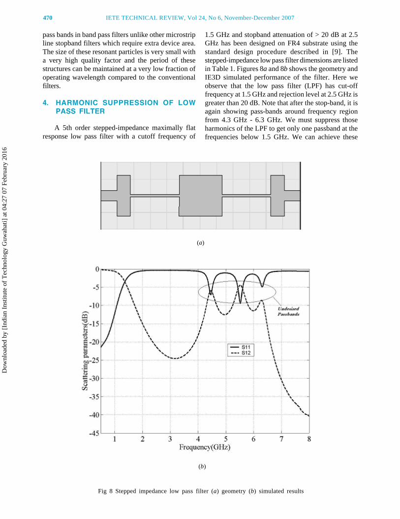
A 5th order stepped-impedance maximally flatresponse low pass filter with a cutoff frequency of
1.5 GHz and stopband attenuation of > 20 dB at 2.5GHz has been designed on FR4 substrate using thestandard design procedure described in [9]. Thestepped-impedance low pass filter dimensions are listedin Table 1. Figures 8a and 8b shows the geometry andIE3D simulated performance of the filter. Here weobserve that the low pass filter (LPF) has cut-offfrequency at 1.5 GHz and rejection level at 2.5 GHz isgreater than 20 dB. Note that after the stop-band, it isagain showing pass-bands around frequency regionfrom 4.3 GHz - 6.3 GHz. We must suppress thoseharmonics of the LPF to get only one passband at thefrequencies below 1.5 GHz. We can achieve these
Fig 8 Stepped impedance low pass filter (a) geometry (b) simulated results
(a)
(b)
Dow
nloa
ded
by [
Indi
an I
nstit
ute
of T
echn
olog
y G
uwah
ati]
at 0
4:27
07
Febr
uary
201
6

TABLE 1: Dimensions of the stepped impedance low pass filters
Equivalent Resistor Capacitor Inductor Capacitor Inductor Capacitorcircuits
Impedance 50 W 20 W 100 W 20 W 100 W 20 W
Length 5 mm 4.026 mm 14.7 mm 13.03 mm 14.7 mm 4.026 mm
Width 3 mm 12.32 mm 0.715 mm 12.32 mm .715 mm 12.32 mm
Thickness 0.035 mm 0.035 mm 0.035 mm 0.035 mm 0.035 mm 0.035 mm
Fig 9 Stepped impedance filter with CSRRs etched in the ground plane (a) geometry(b) simulated results
(a)
(b)
using complementary split ring resonators. The abovestepped impedance filter has been designed with CSRRsetched in the ground plane (refer to Fig 9a) to
demonstrate the signal inhibition properties of CSRRs.Three CSRRs with lengths of 5.7 mm, 5.75 mm, 5.8mm respectively and with width = 1mm, split gap
RAKHESH SINGH KSHETRIMAYUM et al : STOPBAND CHARACTERISTICS 471
Dow
nloa
ded
by [
Indi
an I
nstit
ute
of T
echn
olog
y G
uwah
ati]
at 0
4:27
07
Febr
uary
201
6

472 IETE TECHNICAL REVIEW, Vol 24, No 6, November-December 2007
(a)
(c)
(b)
Fig 10 (a) Stub-CSRR filter (b) stepped impedance filter with stub-CSRR filter and(c) simulated results of stepped impedance filter with stub-CSRR filter
Dow
nloa
ded
by [
Indi
an I
nstit
ute
of T
echn
olog
y G
uwah
ati]
at 0
4:27
07
Febr
uary
201
6

length and width = 0.5 mm (same for all 3 CSRRs)have been etched in the ground plane of the steppedimpedance LPF for harmonic suppression. In Fig 9b,IE3D simulated results of the stepped impedance filterwith CSRRs etched in the ground plane are shown.From Fig 9b, it is clear that at frequency of 3.8 GHz,there is a notch. This occurs because of the presenceof CSRRs in the ground plane. To overcome thisproblem, we will use a CSRR-stub filter similar towhat has been reported in [10]. In this paper, we willuse double stub and CSRR in between the two stubsof the microstrip line as depicted in Fig 10a for theharmonic suppression. In [10], a single stub along withtwo CSRRs has been used to design a low pass filter.Our intention here is to use these double stubs withCSRR to suppress harmonics and these structures ofFig 10a can be used in conjunction with any type offilter for harmonic suppression. A stub with dimensionsw1 = w2 = 6.5 mm, l1 = l2 = 8.59 mm, a1 = a2 = 10 mm,g = t = c = 0.5 mm is used in conjunction with astepped impedance filter which has a cutoff frequencyof 1.5 GHz (refer to Fig 10b for the geometry of thefilter). Such a stub-CSRR filter has a passband tostopband transition at 1.7 GHz. As one can see, theundesired passbands are completely removed ashighlighted in Fig 10c. The rejection bandwidth is verylarge and attenuation level is extremely high (~110 dBat 3 GHz) in the rejection band. Such a steep and widerejection band is not possible with the conventionalharmonic suppression techniques.
5. CONCLUSION
Using the sub-wavelength resonator componentsof left handed metamaterials namely CSRR, compactplanar microstrip stopband filters have been designed.It is very compact having the periodicity smaller thanone tenth of the wavelength at its operating frequency.The dimensions of these particles and the dielectricsubstrate parameters decide their resonant frequency.These types of particles provide an attractive meansfor developing compact filters with fully planarfabrication techniques. This is especially of benefit forthe growing numbers of microwave circuits requiredfor compact integrated circuit (IC) technology forwireless communication applications. Single CSRRparticle in the ground plane gives a very narrow stopband at its resonant frequency with an extremely highQ factor but periodically placing these CSRR structuresgives wide stop bands. As the number of etching ofthese structures increases in the ground plane of thedielectric substrate, the width of the stop band increasesat great extent. Stop bandwidth also depends on theperiod between the structures and it is observed that
as the period of etching such structures in the groundplane of the dielectric substrate decreases the stopbandwidth increases. One of the main advantages ofthese particles is unlike the other conventional filtercomponents/structures, which require large periodbetween them they can be placed very close such thatthe period is smaller than one tenth of wavelength withthe evident enhanced/improved filter performances.Because of this property of these particles the deviceareas are reduced drastically and since they are placedin the ground plane they will not occupy extra devicearea in the design of microwave devices for applicationslike harmonic suppression. A stub-CSRR filter hasalso been investigated for harmonic suppression ofmicrostrip filters. Harmonic suppression of steppedimpedance filter has been achieved successfully usingsuch stub-CSRR filters. A steep and increased out-of-band rejection with very high attenuation level in thestop band of the filter has been observed with the goodin-band filter performance.
ACKNOWLEDGEMENTS
Authors are grateful to the Science and EngineeringResearch Council, Department of Science Technology,Government of India for supporting this study; they arealso thankful to Vipin and Anka for helping in carryingout some of the simulations works and lastly theyappreciate the anonymous reviewers comments whichhas significantly improved the quality of the paper.
REFERENCES
1. R Levy, R V Snyder & G Matthaei, Design ofMicrowave Filters, IEEE Transactions onMicrowave Theory and Techniques, vol 50, no 3,Mar 2002, pp 783-793.
2. C Caloz & T Itoh, Electromagnetic metamaterials:Transmission Line Theory and MicrowaveApplications, New York: Wiley 2004.
3. R Marques, F Medina & R Rafii-El-Idrissi, Role ofbianisotropy in negative permeability and lefthanded metamaterials, Phys Rev B, Condens Matter,vol 65, pp 144 441(1)–144 441(6), 2002.
4. F Falcone, T Lopetegi, M A G Laso, J D Baena,J Bonache, M Beruete, R Marqués, F Martín &M. Sorolla, Babinet principle applied to metasurfaceand metamaterial design, Phys Rev Lett, vol 93,pp 197 401(1)–197 401(4), 2004.
5. F Falcone, T Lapetegi, J D Baena, R Marques,F Martin & M Sorolla, Effective negative-e stopband microstrip lines based on complementary splitring resonators, IEEE Microw. Wireless Compon.Lett, vol 14, no 6, pp 280-282, Jun 2004.
6. R Marqués, J D Baena, J Martel, F Medina,F Falcone, M Sorolla & F Martín, Novel smallresonant electromagnetic particles for metamaterial
RAKHESH SINGH KSHETRIMAYUM et al : STOPBAND CHARACTERISTICS 473
Dow
nloa
ded
by [
Indi
an I
nstit
ute
of T
echn
olog
y G
uwah
ati]
at 0
4:27
07
Febr
uary
201
6

474 IETE TECHNICAL REVIEW, Vol 24, No 6, November-December 2007
and filter design, in Proc Electromagnetics inAdvanced Applications Int Conf, Turin, Italy, Sep2003, pp 439-442.
7. J D Beana, J Bonache, F Martin, R Marques,F Falcone, T Lopetegi, M A G Laso, J Garcia-Garcia,I Gil, M F Portillo & M Sorolla, Equivalent-Circuitmodels for Split-Ring Resonators andComplementary Split-Ring Resonators coupled toplanar transmission lines, IEEE Trans Microw
Theory and Tech, vol 53, no 4, Apr 2005.
8. IE3D version 10.2, Zeland Corp., Freemont, CA, USA.
9. D M Pozar, Microwave Engineering, 3rd edition,John Wiley & Sons, Inc.
10. M K Mandal, P Mondal, S Sanyal & A Chakrabarty,Low Insertion-Loss, Sharp-Rejection and CompactMicrostrip Low-Pass Filters, IEEE Microw WirelessCompon Lett, vol 16, no 11, pp 600-602, Nov 2006.
Rakhesh Singh Kshetrimayumreceived the BTech degree in ElectricalEngineering from the Indian Institute ofTechnology, Bombay and the PhDdegree from the Nanyang TechnologicalUniversity, Singapore. He did hispostdoctoral research from theMicrowave Lab, Indian Institute ofScience, Bangalore and ElectromagneticCommunication Lab, Pennsylvania StateUniversity, University Park, USA. Since 2005 he is a facultymember at the department of Electronics and CommunicationEngineering, IIT, Guwahati and presently he is an AssistantProfessor. His research interests include RF, Microwaves,Antennas, Numerical Electromagnetics and Neural Networks.
* * *
Sridhar Kallapudi received the BE degree in Electronicsand Communication Engineering from the Andhra Universityand MTech degree in Electronics and Communication from the
Authors
Indian Institute of Technology, Guwahati in May 2007. He ispresently with Red Pine Signals. His research interests includeMicrowave Filters, Periodic Structures and Metamaterials.
* * *
S S Karthikeyan received the BEdegree in Electronics and CommunicationEngineering from BharathidasanUniversity, Trichy in 2001 and MEApplied Electronics from SathyabamaUniversity, Chennai in 2005. Currentlyhe is a PhD Research Scholar atDepartment of Electronics andCommunication Engineering, IIT,Guwahati. His research interests includeElectromagnetic Band Gap substrates, Microwave Filters andMetamaterials.
* * *
Dow
nloa
ded
by [
Indi
an I
nstit
ute
of T
echn
olog
y G
uwah
ati]
at 0
4:27
07
Febr
uary
201
6