eu2000i-manual - wordpress.com this manual covers service and repair procedures for the honda...
TRANSCRIPT

������������������������
�������������������
����������������������������������������������������������������������������������������������������������������������������������������������������������������������������������������������������������������������������������������������������������������������������������������������������������������
����������������������������������������������������������������������������������������������������������������������������������������������������������������������������������������������������������������������������������������������������������������������������������������������������������������������������������������������������������������������
�������������������������������������������������������������������������������������������������������������������������������������������������������������������������������������������
��������������������������
����������������������������������������������������������������������������� ��������������� ������������������������������������������������������� ������������������������� �������������������������������������������������������������������
���������������
�������������������� ��� ��������������������������������������������������������������������������������������������������������������������������������������������������� ����������������������������������������������������������������������������������������������������������������������������������������������������������� ��������������������������������������� ������������
�������������������������������������������������������������������������������������������������������������������������������������������������������������������������������������������������������������������������������������������������������������������
����������������������������
� ������������������������������������������������������������������������������������������������������������������������������������������������������������������������������������������������������������������������������
����������������������������������������������������������������������������������������������������������������������������������������������������������������������������������������������������������������������������������������������������������������������������������������������������������������������������������������������������������������������������������������������������������������������������������������������������������������������������������������������������������������������������������������������������������������������������������������������������������������������������������������������������������������
� ����������������������������������������������������������������������������������������������������������������������������������������������������������������������������
�������������������������� ����������������������������� ������ ������������������������������������������������������������������������������������������������������������������������������������������������������������������������������������������������������������������������������������������������������������������������������������
� ������������������������������������������������������������������������������������������������������������������������������������������������������������������������
����������������������������������������������������������������������������������������������������������������������������������������������������������������������������������������������������������
������������������������������������������������
���������� ��������� ����������� ������������ ������
�������������������������������
������� ��������������� ���������������� ��� ����
���������������������������������������������
�������������������� �������������������������������
���������������������������������������������������
������� ��������������� ���������������� ��� ����
�����������������
������������������������
����������

�������
INTRODUCTIONThis manual covers service and repair procedures for the Honda EU2000i generators. A supplement for the EU2000i Companion generator is located in the back of this manual.
All information contained in this manual is based on the latest product information available at the time of printing. We reserve the right to make changes at any time without notice.
No part of this publication may be reproduced, stored in a retrieval system, or transmitted, in any form by any means, electronic, mechanical, photocopying, recording, or otherwise, without prior written permission of the publisher. This includes text, figures, and tables.
As you read this manual, you will find information that is preceded by a symbol. The purpose of this message is to help prevent damage to the generator, other property, or the environment.
SAFETY MESSAGESYour safety and the safety of others are very important. To help you make informed decisions, we have provided safety messages and other safety information throughout this manual. Of course, it is not practical or possible to warn you about all the hazards associated with servicing these generators. You must use your own good judgement.
You will find important safety information in a variety of forms, including:
• Safety Labels – on the generator.
• Safety Messages – preceded by a safety alert symbol and one of three signal words: DANGER, WARNING, or CAUTION.
These signal words mean:
You WILL be KILLED orSERIOUSLY HURT if you don’tfollow instructions.
You CAN be KILLED orSERIOUSLY HURT if you don’tfollow instructions.
You CAN be HURT if you don’tfollow instructions.
• Instructions – how to service these generators correctly and safely.
American Honda Motor Co., Inc.Service Communications Department
NOTICE
DANGER
WARNING
CAUTION
CONTENTS
SPECIFICATIONS 1
SERVICE INFORMATION 2
MAINTENANCE 3
MUFFLER 4
AIR CLEANER/CARBURETOR 5
CONTROL PANEL 6
SIDE COVERS/FUEL TANK/FRONT FRAMES/UNDER COVER 7
RECOIL STARTER/FAN COVER 8
GENERATOR 9CAM PULLEY/CRANKSHAFT/PISTON/CYLINDER BLOCK 10
OPERATION 11
SUPPLEMENT FOR COMPANION
����������

�������
����������

�������1. SPECIFICATIONS
1. SPECIFICATIONS............................... 1-1 4. DIMENSIONAL DRAWINGS................1-4
2. CHARACTERISTICS .......................... 1-2 5. WIRING DIAGRAM..............................1-5
3. PERFORMANCE CURVES................. 1-3
����������

�������
* Values indicate the specifications when the Eco-Throttle™ is OFF
PWM (Pulse width modulation)
����������

�������
����������

�������
����������

�������
����������

�������
����������

�������2. SERVICE INFORMATION
1. SYMBOLS USED IN THIS MANUAL.. 2-1 5. TORQUE VALUES...............................2-5
2. SERIAL NUMBER LOCATIONS......... 2-1 6. SPECIAL TOOLS.................................2-6
3. ELECTRIC PRECAUTIONS................ 2-2 7. TROUBLESHOOTING.........................2-7
4. MAINTENANCE STANDARDS........... 2-3 8. CABLE & HARNESS ROUTING .........2-20
����������

�������
����������

�������
����������
�������������������

�������
����������

�������
����������

�������
����������

�������
����������
�����������������������

�������
����������

�������
����������
�����������������������

�������
����������

�������
����������
�����������������������

�������
c. IGNITION SYSTEMMake a copy of the EU2000i Ignition System Troubleshooting Worksheet (P. 2-13b) and document your test results for future reference or in case you need to call Techline.
1. Turn the engine stop switch to the ON position and pull the starter grip. Verify the Oil Alert® indicator is not flashing.
If flashing, add oil to bring the level to the upper limit.
2. Remove the maintenance cover.
3. Clamp the carburetor inlet fuel line and drain the carburetor float bowl.
4. Remove the air cleaner case (P. 5-1).
5. Remove the spark plug and pull the starter grip several times to remove any unburned fuel from the combustion chamber.
6. Insert the spark plug into the spark plug boot.
7. Set the ignition switch to the ON position.
8. Ground the negative (-) electrode (threaded part) of the spark plug against the shroud.
9. Pull the starter grip and check for spark at the spark plug.
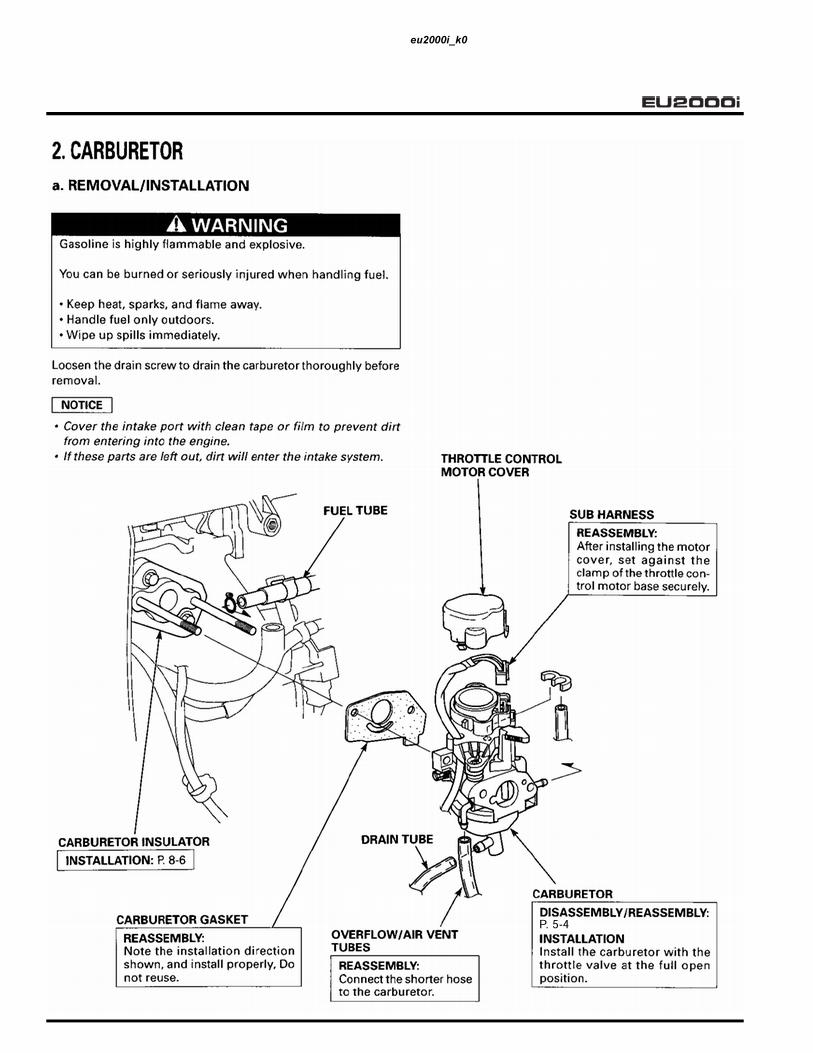
WARNINGGasoline is highly flammable and explosive.
If ignited, gasoline can burn you severely.
Be sure there is no spilled fuel near the engine before performing this test.
OIL ALERT® INDICATOR
HOSE PINCHING PLIERS, SUN-HCP6(Commercially available)
����������
�������
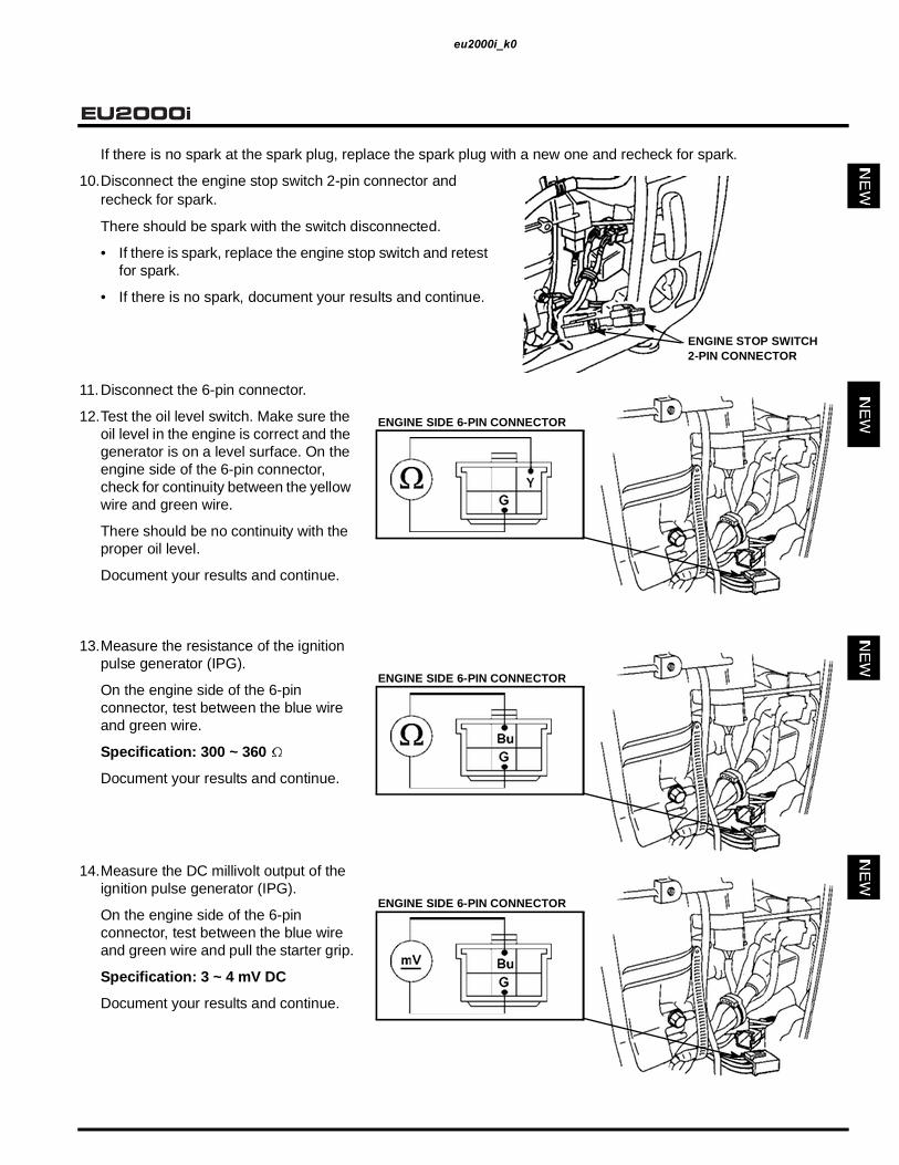
If there is no spark at the spark plug, replace the spark plug with a new one and recheck for spark.
10.Disconnect the engine stop switch 2-pin connector and recheck for spark.
There should be spark with the switch disconnected.
• If there is spark, replace the engine stop switch and retest for spark.
• If there is no spark, document your results and continue.
11.Disconnect the 6-pin connector.
12.Test the oil level switch. Make sure the oil level in the engine is correct and the generator is on a level surface. On the engine side of the 6-pin connector, check for continuity between the yellow wire and green wire.
There should be no continuity with the proper oil level.
Document your results and continue.
13.Measure the resistance of the ignition pulse generator (IPG).
On the engine side of the 6-pin connector, test between the blue wire and green wire.
Specification: 300 ~ 360
Document your results and continue.
14.Measure the DC millivolt output of the ignition pulse generator (IPG).
On the engine side of the 6-pin connector, test between the blue wire and green wire and pull the starter grip.
Specification: 3 ~ 4 mV DC
Document your results and continue.
ENGINE STOP SWITCH 2-PIN CONNECTOR
ENGINE SIDE 6-PIN CONNECTOR
ENGINE SIDE 6-PIN CONNECTOR
ENGINE SIDE 6-PIN CONNECTOR
����������

�������
15.Measure the resistance of the exciter winding.
On the engine side of the 6-pin connector, test between the black/blue wire and green wire.
Specification: 0.2 ~ 0.3 Document your results and continue.
If the exciter winding measures a little over the specification, it may not need to be replaced. Additional resistance of 0.4 ~ 0.5 ohms will not cause a no-spark condition.
16.Measure the AC voltage output of the exciter winding.
On the engine side of the 6-pin connector, test between the black/blue wire and green wire and pull the starter grip.
Specification: 4 ~ 5 VAC
Document your results and continue.
17.Measure the ignition coil resistance.
Disconnect the black bullet connector.
Primary winding: on the engine side of the connectors, measure between the black single bullet connector and the green wire of the 6-pin connector.
Document your results and continue.
Specification: 0.7 ~ 1.1
If the ignition coil measures a little over the specification, it may not need to be replaced. Additional resistance of0.4 ~ 0.5 ohms will not cause a no-spark condition.
Secondary winding: on the engine side of the connector, measure between the green wire of the 6-pin connector and the spark plug cap.
Specification: 12 K ~ 21 K
Document your results and continue.
ENGINE SIDE 6-PIN CONNECTOR
ENGINE SIDE 6-PIN CONNECTOR
ENGINE SIDE 6-PIN CONNECTOR ANDBLACK BULLET CONNECTOR
ENGINE SIDE 6-PIN CONNECTOR ANDSPARK PLUG CAP
����������

EU2000i
�����������������������������������������������������������������������������������������������������������������������������������������������������������������������������������������������������������������
�������������������������������������������������������������������������������
� ������������������������������������������������������������������������������������������������������������������������
� �������������������������������������������������������������
����������
� ����������������������������������������������������������������������������������������������
� ����������������������������������������������������������������������������������������������������������������������������������������
� �����������������������������������������������������
�����������������������������������������������������������������
� ����������������������������������������������������������������������������������������������
������������������������������������������������������������������������������������������������������������������
�������������������������������������������������
��������� ������������� ������������ ���� ����
��������������������������������������������������������������������
���������������� ���������������������������������������
�������������� ����������
����������������� ���������������
������������������ ����������
��������������� ���������
��������������������������������
����������
����������������������������������
���������
���������������������������������������������������������������������������
����������
������������
���������
���������������������
�������������
�����������������
���������
�����������������
������������
����������

�������
����������

�������
����������
�����������������������

�������
����������
�����������������������

�������
e. GENERATOR
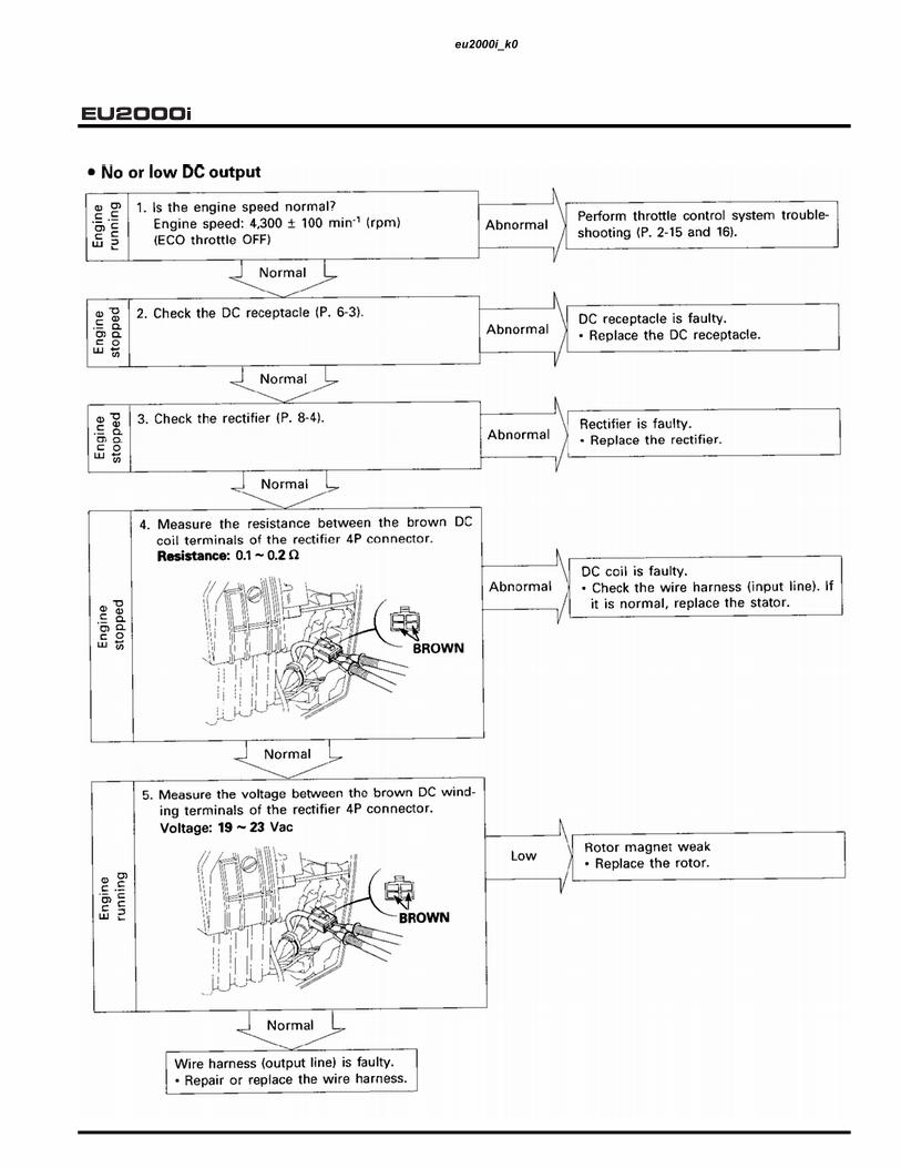
• No or low AC output
�������� ��� ��� ��� �� ������ ��� �������� ����� ���� ���� �������
�������� ������� ������ ����� � ����� ����
�� �������
���������� ������ ��� ��������� ��������
��� ��� � ��
�� ��� � ���� ������� ������ ���� �������
��� ���� ���� ������� ��� ����� ������ ���� ����� ���
��
��
��
���������� ��� ����� ���������� ���� ��� ����� ���������
������������� ��� ���� ��� ��������������������
��
����� ���������
����������������
�������������
���� ������ ������ ��������
���� ��� ���������� �� ���� ������������ ��� �� ���
��
����� ��������� ������������ ��� ������ ���� ���������
��� �������� ����������� ���
��� ���
���� ���
���� ���
������ ���
����� ���
���������� ��� ����������������� �� ���� ��
���������� ��� ����������������� �� ���� ��
������ ���������� �������������� ��� ������� ���� ���������
��
��
�������
���� ������� ��� ���������� ������� �������� �������� ��� ������������� �������� �� ��� ����� ����� �� ��������� ������ �������� ����� �� ��������������
���� ��������� ������ ��� ����� �������� ������������� �������
���
��� ������
������ ����� ���� ��� ��������
�� ���������
������� ��� ������������������ �� ����������
��
������� ��� ��������� ���� ���������
���������� ��� ����������������� �� ���� ��
��� � ���� ���� ���������� ������� ��� ����� ���� ��� ��������� ������� �� ��� ����� ��������� �� ������ ������������� ������� ��������� ��� ��� ����������� ����������� ����� ��� ������� ���� ���� ��� �� ��� ������������������������ ��������
������ �� ����������������� �������� ������ ������ ���� �� ����� �� ��� �� ����������� ��� ��� � ���
� ��� ����������� ������
��
��
��
���� ��� ������ �������� ����� ��� �������� ��������� ����� �� ��� ��� ��� �� ������� ��������� �� ���
����� ��� �� ������ ��������� ������ �� ��� ������� ��� �� ���������� �� ������ �� ��� ����������� �� ���� ������� ������
�����
����������
�����������������������

�������
��
��
����� �� ������ ������� �� ��� ���� �����������
������� ���� ���� �������� ��������� ���� ����� ��� ������������ ������� ����� ��� ���� ���� ��������� ������� ����� ��� ���� ���� ����
��
��������� ���� ������
��
��� ����� ��� ���������������� �������� �� ���������� ������� �� �������������������������� ������ ��� ����������� ������������� ������������ ����������������� �� ��������� ��� ������ ���� ���� ���� ����� ���
��
��� ���
���� ���
����� ���
���� ��������� ���
����� ���������
���� �� ��� ����� ��������� ���� ����������� ���� ��� ���������
������� �� �� ���
���� �� ��������
������ ������
��������� ������
���� �����������
����������
�������
����������

�������
����������

�������
����������

�������
����������

�������3. MAINTENANCE
1. MAINTENANCE SCHEDULE ............. 3-1 6. VALVE CLEARANCE ..........................3-5
2. OIL ALERT.......................................... 3-2 7. FUEL TANK/FUEL FILTER..................3-7
3. ENGINE OIL ........................................ 3-2
4. AIR CLEANER .................................... 3-3
8. FUEL TUBE/FUEL PUMPDIAPHRAGM TUBE............................3-7
5. SPARK PLUG ..................................... 3-4 9. SPARK ARRESTER ............................3-8
����������

�������
��� �� �� ������� � ��
�� �� �������� ��
��
��������������
SAE 10W–30 or SAE30API Service category SJ
Change the oil if it is dirty or contaminated with foreignmaterial.
����������
�����������������������

�������
����������

�������
����������

�������
����������

�������
����������

�������
����������

�������
����������

�������4. MUFFLER
1. MUFFLER............................................ 4-1
����������

�������
����������

�������5. AIR CLEANER/CARBURETOR
1. AIR CLEANER .................................... 5-1 2. CARBURETOR....................................5-2
����������
������
����������

�������
����������

�������
����������
�������������������

�������
����������

�������
����������

�������6. CONTROL PANEL
1. CONTROL PANEL .............................. 6-1
����������
�����������������������

�������
����������
�����������������������

�������
���������������������������������������������������
�
�����������������������������������������������������������
��������������������������������������
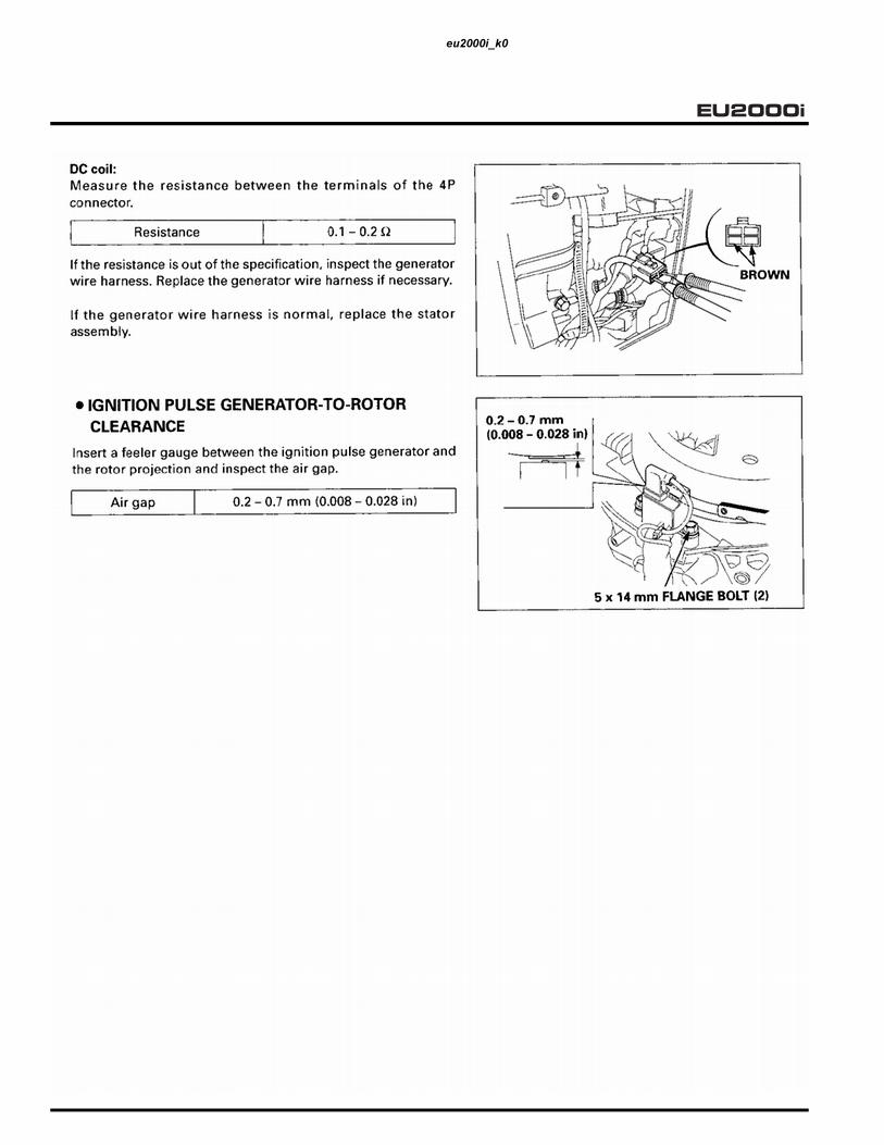
Check for continuity between the switch terminals.
There must be no continuity with the switch turned ON, and continuity with the switch turned OFF.
����������

�������
����������

�������
7. SIDE COVERS/FUEL TANK/.........FRONT FRAMES/UNDER COVER
1. SIDE COVERS .................................... 7-1 3. FRONT FRAMES/UNDER COVER .....7-3
2. FUEL TANK......................................... 7-2
����������

�������
����������

�������
3. FRONT FRAMES/UNDER COVER
4.4 N•m (0.4 kg•f, 3.2 lbf•ft)
6 mm SPECIAL
����������

������
����������

�������
����������

�������
����������

�������8. RECOIL STARTER/FAN COVER
1. RECOIL STARTER/FAN COVER........ 8-12. FAN SHROUD ..................................... 8-5
3. EXHAUST MANIFOLD/CARBURETOR INSULATOR ..............8-6
����������

�������
����������

�������
����������

�������
����������

�������
����������

�������
����������

�������9. GENERATOR
1. GENERATOR ...................................... 9-1 2. BREATHER COVER A/B.....................9-5
����������

�������
����������

�������
����������
�������
����������

�������
����������

�������
����������

�������
10. CAM PULLEY/CRANKSHAFT/PISTON/CYLINDER BLOCK
1. CAM PULLEY .................................... 10-1 5. GOVERNOR....................................... 10-14
2. CRANKCASE COVER/CRANKSHAFT/CYLINDER BLOCK.. 10-5
6. INSPECTION...................................... 10-177. VALVE GUIDE REPLACEMENT ....... 10-24
3. PISTON .............................................. 10-10 8. VALVE SEAT RECONDITIONING ..... 10-26
4. VALVES.............................................. 10-12
����������

�������
����������

�������
����������

�������
����������

�������
����������

�������
����������

�������
����������

�������
����������

�������
����������
�������
����������

�������
����������

�������
����������

�������
����������

�������
����������
�����������������������

�������
����������

�������
����������

�������
����������

�������
����������

�������
����������

�����������
����������

�������
����������

�������
����������

�������
����������

�������
����������

�������
����������

�������
����������

�������
����������

�������
����������

�������11. OPERATION
1. INVERTER TYPE GENERATORCONSTRUCTIONThe Inverter generator has an outer and an inner rotating set of magnets for both the generator and the ignition. The inner set of magnets generate AC in the stator windings, while the outer set generates AC for the ignition coil. A multi-pole coil is used on the stator (15 poles for the AC winding, 6 poles for the DC winding, 1 pole for the sub winding, and 1 pole for the exciter winding). The AC coil in the stator is picked up by the inverter.
Operating Principles When the rotor rotates, the AC (3-phase) is generated at the AC main winding, which is converted into DC by the regulator/rectifier. The voltage is stabilized by the regulator/rectifier in the converter simultaneously. The AC generated at the sub winding becomes the power source for each circuit and elemental device, such as an inverter built-in power transistor. Getting a signal from the oscillator circuit, the inverter that controls the LED generates the AC (single phase) of the proper frequency.
• AC Overload Protection System
The power output indicator light (green LED) is on while the generator is running with normal load. When overloaded, the overload warning light turns on by getting signal from the output current detecting circuit to indicate overloading. When the generator runs overloaded for more than 5 seconds, the circuit cuts off the AC to protect the generator. When the output is cut off due to overloading, stop the engine and disconnect the attached electrical device from the generator to remove the load. Start the engine again. The LED (green) should turn on.
1. INVERTER TYPE GENERATOR......... 11-12. FULL TRANSISTOR IGNITION .......... 11-2
3. ECO-THROTTLE(ELECTRICAL GOVERNOR) ..............11-3
����������

�������
2. FULL TRANSISTOR IGNITION
Operating PrinciplesThe positive (+) and negative (-) power sources are provided from the exciter winding. AC current is provided to the Ignition coil from the negative (-) power source. Current switching to the ignition coil is controlled by the Field Effect Transistor (FET).
The FET turns on when the pulse pole front end reaches the ignition pulse generator and starts to amplify the current in the ignition coil primary winding. The FET turns off when the pulse pole back end has passed the ignition pulse generator, which stops the current in the ignition coil primary winding. The high voltage is then generated in the ignition coil secondary winding (ignition point).
• Rev Limiter
The engine is equipped with a rev limiter to protect the generating system from excessive engine speed. The rev limiter receives its signal from the ignition pulse generator. If the engine speed reaches a predetermined level, the rev limiter will be activated and will cut off the ignition system.
• Oil Alert® System
The Oil Alert® unit will cut off the ignition system when the engine oil falls to a predetermined level by turning on the oil level switch and the red light emitting diode (LED), which acts as a warning light. The red LED will remain lit approximately two seconds after engine stops using electrical energy from the condenser in the ignition control module.
• Electrical Source
The engine is operated by the dual electrical source: the positive (+) half-wave and the negative (-) half-wave. The diodes convert AC that is generated at the exciter winding to the positive (+) half-wave and the negative (-) half-wave AC currents. The positive (+) half-wave becomes the power source for the rev limiter while the negative (-) half-wave becomes the power source for the ignition system and the Oil Alert® unit. Both of the half waves become the power source for the FET gate drive. This system realizes a stable rev limiter activating condition and a Field Effect Transistor (FET) ignition system.
����������

�������
3. ECO-THROTTLE (ELECTRICAL GOVERNOR)
Operating Principles• Variable Engine Speed
The inverter’s CPU compares the current output voltage, current and engine speed with what is programed it its memory and sets the throttle position accordingly. The actual required engine speed then is based on generator load ratio and temperature. As a load is applied, the engine speed, generator output power will drop momentarily. The inverter will calculate the type of load (how much of power drop is occurring) and set the engine speed accordingly.
• Engine Stall Prevention System
Detecting the engine load by the throttle opening the system prevents engine speed from going down when the load is excessively high, beyond engine load capacity by controlling the output voltage at the inverter. This system is able to generate maximum power more efficiently, and control peak performance for applications that require more electric power, such as motors. The system automatically activates higher engine speeds in order to compensate for the power loss of the engine when used in the high altitude or deterioration if the generator caused over time.
����������

�������
����������

�������� ���������
������������
����������

����������

��������������������
������������
�������������������������������������������������������������������������������������������������������������������������������������������
���������������������������������������������������������������������������������������������������������������������������������������������������������������������������������������
���������������������������������������������������������������������������������������������������������������������������������������������������������������������������������������������������������������������������������������������������������������������������������
������������������������������������������������������������������������� �������������������������������������������������������������������������������������������������������������������
���������������
���������������������������������������������������������������������������������������������������������������������������������������������������������������������������������������������������������������������������������������������������������������������������������������������������������������������������������������������������
����������������������������������������������������������������������������
� ���������������������������������
� ���������������������������������������������������� ������������������������������������������������������������
���������������������������
��������������������������������������������������������������������
�������������������������������������������������������������������
������������������������������������������������
� ��������������������������������������������������������������������
���������������������������������������������������������������
������
�������
��������
��������
��������
������������������
�������������� �
������������������� �
����������� �
������� �
���������������������� �
������������� �
����������������������
�������������������������
������������������������ �
��������� �
����������������������
�����������������������
��������� ��
��������������������������������������������������������������������������������
����������

��������������������
����������

�������������������� OUTLINE OF CHANGES
�������������
���������
������������
���������
�������������
�������������
������������
�������������
������������
�������������
������������
EU2000iEU2000i Companion
����������

��������������������
����������

��������������������1. SPECIFICATIONS
1. SPECIFICATIONS............................... 1-1 3. DIMENSIONAL DRAWINGS................1-4
2. CHARACTERISTICS .......................... 1-2 4. WIRING DIAGRAM..............................1-5
����� �����������������
���� ��������������
�������������� ����������������
������������� ����������������
�������������� ����������������
���������� �����������������
���������������� �����������������
�� ������������������������������������
������
����� �����
���������������� �����
���� �������������������������������������������
������������ �������� ������������
������������� ������������������������������
����������������� ����� �������
�������������� ����������
��������������� ���������������
��������������� ��� � �� ���������
���������� ������������
���������� �������������������������������������������
����������� �������������
�������� �����������������������
������������������ �������������
������������ ����� �������������������������
��������������� ����������
��������������� ��������������
��������������� �������������������������������
��������� ������������������������������������������
�������������������
�����������������������
����������

��������������������
���������
����� �����������������
���������������� ����
�������������� �������������������������������
������������������� ��������������������������������
���������� �����������������������������
������������������������� ����������������������������
����� ������������
������������������ �������������������������������������
�������������������� ��������������������������������
����� �����������������
���� ��������
�������������� �������
��������������� �������
��������������� �����
���������������� �����
���������������� ������
������������ ��� ����
���������
�������
������������
���������
�������
�����������
����������������� � ��������
���������
�������
������������
��������
��������
�����������
������������������� � �����������
��������������������� ���� ����
�������������������� ������
������������������ ���� ���������������������������
����������������
������������������� ������������������������������
���������������
�����������������������������������������������
������������������������� �������������
�� ���������������
�������
���������
����
���������
���������
����
����������

��������������������
�� ��������������������
����������������
����������

��������������������
�� ��������������
����������

��������������������2. SERVICE INFORMATION
1. CABLE & HARNESS ROUTING......... 2-1
�� ��������������������������������������
�������������������������
�������������
�������� ��������� ��� �������������
������
�����
�������������
������������
�������������
������������
�����
���
�������������
�������
���������������
����������
���������������
����������
�����
���
�����
������������������
������
���������
����������
��������������
������
����������������
������
������������
�������
�����
��������
���
�������������
����������

��������������������
����������

��������������������6. CONTROL PANEL
1. CONTROL PANEL .............................. 6-1
������
�����������������
���������
�� ������������������������������������
�� ����������������������������������������������������������������������������������������������������������������
��������������
�� ����������������������������������
�� ������������������������������������������
�����������
�������������
���������������������
���������������
��������������������
�����������������
���������
����������
������������
�������������������
�������������
��������
������������
������������������
����������

��������������������
�������
�����
�������������������
�������������������������
�������������
������������
������������������
��� ���� ����� ����
�������
�������������
������������������
������������
������������������
����������
���������������
������������������
��� ���� ����� ����
�������
������������
����������������������
������������������
���������
���������
���������
���������
�������
���������
��������
���������
���
�����������
����������
����
��������������
��������������������
������������������
����������������
������
������������������
��� ���� ����� ����
�������
�������������
������������
������������������
��� ���� ����� ����
�������
�������������
�������������������������������
����������������
��������������� ������� ��������
������������
��������
���������
����������
����
����������

NOTES
����������

NOTES
����������

NOTES
����������

����������

�����������������������������������������������������������������������������������������������������������������������������������������������������������������������������������������������������������������