issn: implementation and optimization … and optimization under matlab code of a hv power...
TRANSCRIPT

Journal of Theoretical and Applied Information Technology 30th November 2011. Vol. 33 No.2
© 2005 - 2011 JATIT & LLS. All rights reserved.
ISSN: 1992-8645 www.jatit.org E-ISSN: 1817-3195
227
IMPLEMENTATION AND OPTIMIZATION UNDER MATLAB CODE OF A HV POWER TRANSFORMER FOR
MICROWAVE GENERATORS SUPPLYING TWO MAGNETRONS
1M.OULD.AHMEDOU, 1M.FERFRA, 2N.EL GHAZAL, 2M.CHRAYGANE, 1M.MAAROUFI
1Electrical Engineering, Power electronics Laboratory EMI, Mohammadia’s School of Engineering
Mohamed V University, Rabat, Morocco. BP: 765 Avenue Ibn Sina, Agdal - Rabat – Morocco. 2MSTI Laboratory ESTA, Technology higher school Agadir, Ibn Zohr University Agadir, Morocco.
E-mail: [email protected]
ABSTRACT
The design of this new power supply uses a HV single phase leakage flux transformer supplying two cells, composed each one of a capacitor and a diode, which multiplies the voltage and stabilizes the current. Each cell supplies in turn a single magnetron. This paper treats firstly, a new modeling of this transformer with shunts of HV power for N=2 magnetrons. This model is based on the determination of analytical expressions of nonlinear storable inductances, from the fitting of the magnetization curve B(H) of the material used. The resulting model will be implemented for the first time under MATLAB-SIMULINK® tool where we compare the results from this model to those obtained from the old model validated by EMTP. In a second step, using the programming tool MATLAB, we discussed an optimization strategy of this new HV power supply for the microwave generators with N=2 magnetrons, to envisage the possibility of obtaining gains in section, space, and weight, and to reduce the transformer cost, and therefore that of all the installation, while respecting the conditions recommended by the constructor: Ipeak < 1.2 A, Imean ≈ 300 mA.
Keywords: Electromagnetic Transient Program (EMTP); magnetic circuit ; magnetron ; MATLAB-SIMULINK ; microwaves; modeling ; optimization ;high voltage (HV).
1. INTRODUCTION
In a microwave installation, the classic HV supply for one magnetron 800 Watts - 2450 MHz is composed essentially of three parts: a single phase leakage flux transformer, a cell composed of a capacitor and a diode, which doubles the voltage and stabilizes the current [1]-[2]-[11]-[13].
The modeling of this HV power is based on the dimensioning of its HV transformer with shunts, which ensures the stabilization of the magnetron anodic current thanks to its storable magnetic circuit. Contrarily to the traditional transformer, the leakage flux in the shunts is of the same order of magnitude as the two primary and secondary fluxes.
The previous works present in literature dealing with modeling this special transformer are rare contrarily to the conventional transformers which are abundant [3-[4]-[5]-[6]-[8]-[9]-[10]. To our knowledge, the principal works in this research
were done by Chraygane when he was developing two T and π models quadruples equivalents of the transformer with shunts [10]. The complexity of the nonlinear inductances expressions of T quadruple model has rendered its exploitation difficult by the EMTP code. However, each nonlinear inductance of a π quadruple model is directly related to the corresponding reluctance.
This π quadruple model retained in this work [10] was simulated by the EMTP code by introducing point by point the magnetization curve B (H) and taking into account the saturation phenomena. The simulation results are in a good agreement with experimental ones. In another work [1], we implemented and validated the same π model of transformer with magnetic shunts under the MATLAB-SIMULINK® code.
This tool has allowed us to introduce an unlimited number of points on the magnetization curve B (H). Contrary to EMTP code that accepts

Journal of Theoretical and Applied Information Technology 30th November 2011. Vol. 33 No.2
© 2005 - 2011 JATIT & LLS. All rights reserved.
ISSN: 1992-8645 www.jatit.org E-ISSN: 1817-3195
228
only a limited number of points of this curve. By the way, a new device of a global high voltage power supply for microwave generators with N magnetrons (treated case N = 2) used as an energy source in industrial applications has been approached [2]. The behavior of the HV equivalent circuit of this power was validated by EMTP code, by introducing the magnetization curve B (H) point by point. Our interest in this paper is firstly, to improve a model of transformer supplying N = 2 magnetrons and, secondly, to optimize this high voltage supply. The paper is organized as follows:
In a first step, we present a new π quadruple model of the new HV power supply for a microwave generators with N=2 magnetrons. This model is based on the determination of analytical expressions of nonlinear storable inductances, from the fitting of the magnetization curve B (H) of material used.
The resulting model will be implemented for the first time under MATLAB-SIMULINK tool where we compare the results of this model with those obtained by the old model validated by EMTP [2]. In a second step, using the programming tool MATLAB, we discussed the optimization of this new HV power supply for the microwave generators with N=2 magnetrons, and to envisage the possibility of obtaining gains in section, space, and weight, to reduce the transformer cost, and therefore that of all the installation, while respecting the conditions recommended by the constructor: Ipeak < 1.2 A, Imean ≈ 300 mA.
Fig 1: New HV power for microwave generator a N = 2
magnetrons
The objective function to minimize is the volume of iron and copper which are depending of the following optimization variables:
• Size of the magnetic circuit characterized by the width of the core unwound a.
• Number of secondary turns n2 • Size of each air-gap between each of the
two shunts and magnetic circuit e. • Thickness of each shunt materialized by the
number of stacked sheets n3.
2. MODELING OF THE NEW HV POWER SUPPLY OF MICROWAVE GENERATOR WITH N = 2 MAGNETRONS
The structure cuirassed of transformer with
magnetic shunts of the new power supply for two magnetrons [2] is identical with that on to transformer of a classic power supply for a single magnetron [10]; all theoretical modeling developed in may therefore be applied.
2.1. Theoretical study of transformer with shunts
2.2. Description Fig.2 shows the armored structure of the
transformer used in the industrial applications using the traditional HV supply for one magnetron. Magnetic shunts are used to deviate an important part of flux circulating between the primary and secondary windings. Taking into account the size of the residual air-gaps and saturation state of materials, the magnetic fluxes in the air can be considered negligible compared to the flux through the shunts. The geometry of the magnetic circuit is symmetrical compared to the central core, having a double section of that common to each side core and each cylinder head.

Journal of Theoretical and Applied Information Technology 30th November 2011. Vol. 33 No.2
© 2005 - 2011 JATIT & LLS. All rights reserved.
ISSN: 1992-8645 www.jatit.org E-ISSN: 1817-3195
229
Fig. 2. Section of cuirassed transformer with shunts
2.3. Electric and magnetic equations The transformer is considered without iron losses
due to the hysteresis and eddy currents. Only the phenomenon of saturation is taken into account. The operation of the transformer is characterized by the following complete electric and magnetic equations system:
(1)
(2) (3)
(4) (5)
(6)
By transforming the equations (1) to (6), we obtain the following equations governing the operation of π quadruple model representative of transformer referred to secondary [10]:
′ ′ ′ ′ ′ (7)
(8) ′ ′ (9)
′ ′ ′ (10) ′ (11)
The advantage of the quadruple model (Fig.3) is in its equivalent single-phase scheme referred to the secondary which seems more convenient to study the operation of this transformer using code SIMULINK or EMTP. This model is described as natural because each inductance with iron core is directly related to the reluctance of a precise part of the magnetic circuit. Indeed, inductances LP and LS are respectively related to the primary reluctance RP
and secondary reluctance RS of the portions of magnetic circuit.
Indeed, inductances LP and LS are respectively related to the primary reluctance RP and secondary reluctance RS of the portions of magnetic circuit. The inductance (L’Sh) is related to the reluctance of the part of the magnetic circuit including the two identical shunts, each of which has two identical air-gaps of small thickness (Fig.2). The immediate relevance of this model is to be able to assign to each inductance a nonlinear "flux-current" relation of the form n2Ф (i), from the geometrical parameters of a magnetic circuit specific portion of the transformer, thus allowing reflecting its real behavior in nonlinear mode.
Fig.3: HV circuit supply of the simulated magnetron with a
SIMULINK code in nominal operation (nonlinear)
3. IMPROVED MODEL
The solution of field problems involving ferromagnetic materials is complicated by the nonlinear relationship between B and H. One of the problems encountered is the absence of single mathematical expression, to represent the magnetization curve characteristic over a wide range of magnetic fields, having a smooth variation of the incremental permeability.
As well in our previous work [1], the B-H curve introduced in the π old model of this special transformer and based on a set of measurement data is approximated under software tools (EMTP, SIMULINK) by several straight line segments connecting the points of measurements. But apparently, such B-H curve obtained is not smooth at the joints of the segments and the slopes of the
Journal of Theoretical and Applied Information Technology 30th November 2011. Vol. 33 No.2
© 2005 - 2011 JATIT & LLS. All rights reserved.
ISSN: 1992-8645 www.jatit.org E-ISSN: 1817-3195
230
straight lines representing the permeability are discontinuous at these joints [20].
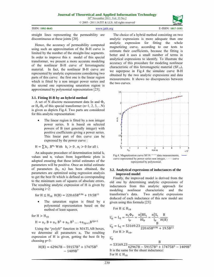
Hence, the accuracy of permeability computed using such an approximation of the B-H curve is limited by the number of the straight-line segments. In order to improve this π model of this special transformer, we present a more accurate modeling of the nonlinear B-H curve of ferromagnetic material. In fact, the nonlinear B-H curve are represented by analytic expressions considering two parts of this curve: the first one is the linear region which is fitted by a non integer power series and the second one representing saturation region is approximated by polynomial representation [23].
3.1. Fitting H-B by an hybrid method A set of N discrete measurement data In and Фn
or Hn-Bn of this special transformer (n=1, 2, 3,…N) is given as depicts Fig.4. Two parts are considered for this analytic representation:
• The linear region is fitted by a non integer power series. It is based on selected powers of B (not generally integer) with positive coefficients giving a power series. This linear part of this curve can be expressed by the power curve :
H ∑ k . B With k 0 , n 0 for all i.
An adequate procedure of determination initial ki values and ni values from logarithmic plots is adopted ensuring that these initial estimates of the parameters will be positive. Once an initial estimate of parameters (ki, ni) has been obtained, the parameters are optimized using regression analysis to get the best fit which is defined as corresponding to the minimum sum of squares of absolute errors. The resulting analytic expression of H is given by choosing i=2:
for H H H B 220.65B . 19.5B
• The saturation region is fitted by a polynomial representation based on the method of least squares.
for H H
H a . B a . B a . B … . a B
Using the “polyfit” function in MATLAB boxes, we determine all parameters ai. The resulting expression of H is given, getting the best fit by choosing p=3:
H B 62967B 59157B 17475B1409B
The choice of a hybrid method consisting on two analytic expressions is more adequate than one analytic expression for fitting the whole magnetizing curve, according to our tests to estimate their coefficients, because the fitting is better and it uses a small number of terms in analytical expressions to identify. To illustrate the accuracy of this procedure for modeling nonlinear characteristic of this ferromagnetic material (SF19), we superpose in Fig.4 the simulate curve B-H obtained by the two analytic expressions and data measurements. It shows no discrepancies between the two curves.
Fig.4. Magnetization curve SF19: ° ° ° data measurements, curve represented by power series non integer, - - - - curve
represented by polynomial.
3.2. Analytical expressions of inductances of the improved model
Finally, the improved model is derived from the old one by determining analytic expressions of inductances from this analytic approach for modeling nonlinear characteristic and the transformer’s data. Two analytic expressions deduced of each inductance of this new model are given using this formula [23]:
For H H
L Ln Ф
in BS
Hln S
l .B
H B
L L 53169.23B
220.65B . 19.5B For H H ,
L
53169.23B
62967B 59157B 17475B 1409B It is the same for the shunt inductance: For H H

Journal of Theoretical and Applied Information Technology 30th November 2011. Vol. 33 No.2
© 2005 - 2011 JATIT & LLS. All rights reserved.
ISSN: 1992-8645 www.jatit.org E-ISSN: 1817-3195
231
Ln Ф
in . 2. Ф
Hln . 2 B. S
Hl2n B. S
Hl
L 69346.5B
H B
L 69346.5B
220.65B . 19.5B For H H
L
69346.5B
62967B 59157B 17475B 1409B
3.3. Simulation curve of the new HV power supply for microwave generator with N = 2 magnetrons
In the simulation of our new model, the three nonlinear inductances (primary, secondary and shunt) as shown Fig.3 are function of induction or flux. The implementation of each nonlinear inductance with its analytic expressions under MATLAB-SIMULINK software was realized by using the blocks shown in Fig. 5. The other simulation data of the model are given in Fig.3 and Appendix.
Fig. 5. Implementation of each nonlinear inductance under
MATLAB-SIMULINK
We superpose in Fig.6.A and Fig.6.B the simulation results of this new model, obtained by MATLAB-SIMULINK code with those obtained from old one by EMTP under the same conditions.
These shapes resulting from the two codes under nominal operation (U1=220 V, f=50 Hz) are consistent each other (Fig.6), especially the magnetron current curves which respect the maximum current magnetron constraint (Ipeak < 1.2A) recommended by the manufacturer.

Journal of Theoretical and Applied Information Technology 30th November 2011. Vol. 33 No.2
© 2005 - 2011 JATIT & LLS. All rights reserved.
ISSN: 1992-8645 www.jatit.org E-ISSN: 1817-3195
232
Fig. 6. B. Simulation with EMTP (- - -) and MATLAB-
SIMULINK ( ) code: Forms of current waves (nominal operating)
4. OPTIMIZATION OF HV POWER FOR THE MAGNETRON
4.1. Principle of the optimization The idea is to exploit the improved π quadruple
model of this transformer cited previously by MATLAB SIMULINK, in order to reveal compared to the case of references (see Appendix) the sensitivity of the magnetron current with respect to the variations of one or several geometrical parameters of construction of the transformer. We want in present paper to consider an optimization of the parameters of the transformer presenting a minimum volume of iron and copper. To do this, we carry out sets of simulations in which we target the following objectives:
The first one is to show, by exploiting the π quadruple model by MATLAB SIMULINK, the influence of the variation of each geometric parameter of the transformer (see Appendix) on the magnetron current. The geometric parameters of the transformer considered as variables are:
• The size of the magnetic circuit a (mm). • The number of secondary turns n2. • The size of the shunt materialized by the
number n3. • The width of the air gap e (mm).
The second objective is to present a strategy which allows the simultaneous variation of parameters. This strategy allows to optimize the storable transformer with shunts of HV power, and can lead to different solutions that respond to the criteria recommended by the constructor (Ipeak < 1.2 A, Imean ≤ 300 mA).
4.2. Influence of different parameters Being aware that all the inductances of π
quadruple model are dependent on the geometric parameters of the transformer, the variation of such parameter changes the overall operation of the equivalent circuit of the HV power supply (Fig.1). Therefore, the study of its influence leads us to perform a series of simulations in order to respond to the first objective. In each simulation, we observe the waveforms of the various electrical quantities of the HV circuit and especially those giving the shape of magnetron current, by recording each time its maximum and average values.
To meet to second objective, our approach is based on an iterative method based on the study of the sensitivity of the current magnetron with respect to the simultaneous variation of these parameters.

Journal of Theoretical and Applied Information Technology 30th November 2011. Vol. 33 No.2
© 2005 - 2011 JATIT & LLS. All rights reserved.
ISSN: 1992-8645 www.jatit.org E-ISSN: 1817-3195
233
This strategy pushes us to study the simultaneous influence of one or several parameters on the various characteristics of HV circuit for N=2 magnetrons and particularly those of the current magnetrons, thus leading to several solutions of searched parameters using the MATLAB function "fmincon" as described in paragraph V. In the following, we include non-exhaustive examples that show the influence of some of these parameters on the maximum and average current magnetron.
4.2.1. Influence of “a” on magnetron current The unique variation of the width "a" of the
unwound core of the transformer in a definite range (between 40 and 60 mm), maintaining other fixed parameters, modifies the maximum and average values of magnetron current obtained by simulation. In fact, by recording the maximum and average values of the current magnetron we obtain Fig.7 which presents the variations of these values according to “a”.
Fig.7. Influence of “a” on magnetron current (maximum and
average values) The results of Fig.7 show that the maximum
current of the magnetron decreases when “a” decreases as well as its average value. We can thus diminish “a”, reducing the volume of transformer magnetic circuit, while respecting the constraints recommended by the constructor and without damage to the magnetron tube.
4.2.2. Influence of “n2” on magnetron current The single variation in the number of secondary
turns n2 was conducted between 2000 and 3000 for all simulations, adapting each time the number of turns of the primary winding as necessary to ensure that the transformation ratio remains constant. The other parameters were kept constant.
Fig.8 shows the average and maximum current magnetrons deducted from each simulation for the different values of n2. We note that the maximum value decreases as the number of secondary turns decreases, as well as the average value. It is
possible to diminish the volume of copper by reducing the number of turns in a way that the current remains in the range of magnetron current recommended by the constructor.
Fig.8. Influence of n2 on magnetron current (maximum and
average values) 4.2.3. Influence of “n3” on magnetron current
The electrical operation of the new HV power supply under nominal conditions was simulated for different sizes of each shunt of the transformer; the other parameters were unchanged. By varying the number of stacked sheets of each shunt between 12 and 20, it changes the overall operation of the HV circuit. In each simulation, we observed for each size of the shunt the different characteristics of the circuit mainly HV and that of the magnetron current; this allows us to trace the results shown in Fig.9.
In this figure, we find that the maximum current magnetron decreases when the number of sheet constituting each shunt increases, while the average value of current magnetron remains within acceptable limits. So, there is benefit in minimizing the size of shunts without damage to the magnetron tube.
Fig.9. Influence of n3 on magnetron current (maximum and
average values)

Journal of Theoretical and Applied Information Technology 30th November 2011. Vol. 33 No.2
© 2005 - 2011 JATIT & LLS. All rights reserved.
ISSN: 1992-8645 www.jatit.org E-ISSN: 1817-3195
234
5. OPTIMIZATION STRATEGY
From the results obtained in the preceding paragraph, which show the sensitivity of current magnetron towards the change of the various geometrical parameters of the transformer, we defined a strategy based on the algorithm SQP which can be easily used in the MATLAB toolbox optimization using the function “fmincon”.
This strategy aims to select a simultaneous reduction in the number of turns n2, the width a, the air gap e and the number of sheets stacked in the shunts n3, which turns the volume minimum of magnetic circuit. The effect of the simultaneous change of parameters, compared to the case of the reference transformer [2] may change in more accentuated way the electric operation of the HV circuit of power supply, in particular the waveform of the magnetron current, its maximum and average values.
• Algorithm of optimization
To carry on the optimization of the HV power generator for microwave magnetron N = 2, we decided to implement the Sequential Quadratic Programming (SQP) method. This gradient-based algorithm is considered one of the most efficient approaches to obtain the optimal solution in Non Linear Programming (NLP). Similarly to Newton’s unconstrained optimization method, SQP creates in each step towards the objective a local model of the problem and solves it. Then, based on that result, it continues its path to an optimal solution.
The main difference of SQP relative to other methods is that the former tries to solve the nonlinear program directly instead of transforming it in a sequence of unconstrained minimization problems. Furthermore, SQP is widely applied in engineering problems and it can be easily handled in MATLAB using the ‘fmincon’ function in the optimization toolbox [7].
This algorithm minimizes a given objective function within the constraints determined by the user. To fit our model to this algorithm, we defined our objective function, which is the volume (in Cm3) of iron and the copper of the transformer with shunts:
V X 24 a 1e 6 0.00134 n3a 2 e 1e 3 0.03
4pi2 1e 8
n2n2
10.71432 1e 3 a 0.03
Where X the vector which is composed of the geometrical parameters of construction of the transformer
X a, n , n , e with an initial value
X 50, 2400, 18, 0.55 which represents the values of reference case.
In addition, the constraints in the following table have been redefined as inequality constraints ≤ 0.
Parameter Name Variation range a(mm) : core width unwound
40 ≤ a ≤ 50
n2 : number of secondary turns
2000 ≤ n2 ≤ 3000
n3 : number of stacked sheets of a shunt
12 ≤ n3 ≤ 20
e(mm) : thickness of the air gap
0.25 ≤ e ≤ 1
Table.1. Range of parameter variations
Our study has resulted in practically the following procedure:
For each iteration, we simulated the π quadruple model by using the “sim” function in the MATLAB toolbox which respects the following conditions:
If [The maximum value of the current (Ipeak) in each magnetron < 1.2 A, and
The average value of current (Imean) in each magnetron ≤ 300 mA ]
The program shows us the results: Ipeak Imean, X, V (X). Else the program continues to the next iteration.
The advantage of this method makes it possible
for the industrial decision maker to choose themselves the solution which interests them among the optimal solutions of the multicriteria problem contrary to the methods of evolutionary optimization which can lead to only one optimal solution. The validation of this procedure was carried out for all the possible configurations of the geometrical parameters of the transformer, by running simulations necessary by MATLAB

Journal of Theoretical and Applied Information Technology 30th November 2011. Vol. 33 No.2
© 2005 - 2011 JATIT & LLS. All rights reserved.
ISSN: 1992-8645 www.jatit.org E-ISSN: 1817-3195
235
making it possible to predict the electric behavior of circuit HV of this nominal mode supply.
6. RESULTS
Table 2 recapitulates the selected solutions that can to give the best operation of the magnetron. We selected the solutions in Table 2 that meet the criteria recommended by the constructor and which can operate in nominal state the HV supply for N = 2 magnetrons.
a (mm)
n2 n3 e (mm)
V (cm3)
Ipeak (A)
Imean (mA)
A 50 2300 17 0.55 1837.5 1.015 280
B 44 2150 16.9 0.6 1454 0.745 241
C 40 2150 16.8 0.646 1181.6 0.813 230
D 40 2150 16 0.65 1181 0.81 230
Table 2: Selected solutions responding to the specifications
We find that the solution D allows
simultaneously the best compromise between the gains of section iron and copper so the best gain in space and cost of the transformer with shunts. Simulations resulting from this optimized solution give currents wave forms in each magnetron (which are identical) simulated by MATLAB in nominal mode under 220V. They show that these results don’t present any oscillations affecting the tube magnetrons and respect the constraints recommended by the constructor: Ipeak < 1.2 A, Imean ≈ 300 mA (Fig.10).

Journal of Theoretical and Applied Information Technology 30th November 2011. Vol. 33 No.2
© 2005 - 2011 JATIT & LLS. All rights reserved.
ISSN: 1992-8645 www.jatit.org E-ISSN: 1817-3195
236
7. CONCLUSION
A new π quadruple model of the transformer with shunts supplying N = 2 magnetrons used in industrial applications has been presented and validated. It is based on a determination of analytic inductances deduced by a new analytic approach of fitting the nonlinear B-H curve.
We have proved also under MATLAB code, the influence of one or more parameters on the magnetron current by realizing simulations in which we observe their influence on the magnetron current. In order to optimize the size of this transformer, we have used the “fmincon” function in MATLAB toolbox that is based on the SQP algorithm. This method allowed us to optimize the transformer shunts while respecting the conditions recommended by the constructor Ipeak <1.2 A, Imean ≈ 300 mA. This optimization enables us to reduce the volume of iron and copper of this transformer, thus the weight, and the cost of all the installation.
8. APPENDIX
During this work, we took as references the parameters of the model of the transformer with magnetic shunts whose values are:
a: width of the core unwound = 50 mm. b: width of the magnetic circuit corresponding to the number of stacked sheets of material SF19 = 30 mm. n2: number of secondary turns = 2400. n3: number of stacked sheets of a shunt = 18. e: thickness of air gap = 0.55 mm. h=0.5*n3
Fig.11. geometric parameters of the transformer (reference case)
REFERENCES
[1]. M.Ould.Ahmedou, M.Chraygane, M.Ferfra, “New π Model Validation Approach to the Leakage Flux Transformer of a High Voltage Power Supply Used for Magnetron for the Industrial Micro-Waves Generators 800 Watts”. International Review of Electrical Engineering (I.R.E.E.), Vol. 5. n. 3. May-June.2010. pp. 1003-1011.
[2]. M.Ferfra, M.Chraygane, M.Fadel, M.Ould Ahmedou. “Non linear modelling of an overall new high voltage power supply for N=2 magnetrons for industrial microwave generators” Physical and Chemical News 54, pp. 17-30, 2010.
[3]. H. Ouaddi, S. Baranowski, Nadir Idir, “High frequency modelling of power transformer: Application to railway substation in scale model” Przeglad Elektrotechniczny (Electrical Review), 2010. pp. 165-169,

Journal of Theoretical and Applied Information Technology 30th November 2011. Vol. 33 No.2
© 2005 - 2011 JATIT & LLS. All rights reserved.
ISSN: 1992-8645 www.jatit.org E-ISSN: 1817-3195
237
[4]. Jouni Pylvänäinen, Kirsi Nousiainen, Pekka Verho “Studies to Utilise Calculated Condition Information and Measurements for Transformer Condition Assessment”. International Review of Electrical Engineering (I.R.E.E.). Vol. 4. n. 4. june.2009. pp. 684-689.
[5]. M. Chraygane, M. Ferfra, B. Hlimi, “Détermination analytique des flux et des courants du transformateur à fuites d’une alimentation haute tension à magnétron pour générateurs micro-ondes industriels 800 Watts à 2450 Mhz” Physical and Chemical News PCN, 40 (2008) 51-61.
[6]. A. D. Theocharis · J. Milias-Argitis · Th. Zacharias, “Single-phase transformer model including magnetic hysteresis, and eddy currents” Electr Eng vol. 90, 2008, pp. 229–241.
[7]. Satoru Hiwa, Tomoyuki Hiroyasu, Mitsunori Miki. “Hybrid optimization using DIRECT, GA, and SQP for global exploration”. IEEE Congress on Evolutionary Computation'2007. pp.1709~1716.
[8]. M. Chraygane, M. Ferfra, & B. Hlimi, “Etude analytique et expérimentale des flux du transformateur à shunts d’une alimentation pour magnétron 800 Watts à 2450 Mhz”, revue Physical and Chemical News, PCN, 27, (2006) 31-42.
[9]. B. Kawkabani, J.-J. Simond, “Improved Modeling of Three-Phase Transformer Analysis Based on Magnetic Equivalent Circuit Diagrams And Taking Into Account Nonlinear B-H Curve”, Journal Electromotion, Volume 13, Number 1, January-March 2006, pp. 5-10.
[10]. Chraygane M., ferfra M. & Hlimi B., “Modélisation d’une alimentation haute tension pour générateurs micro-ondes industriels à magnétron”, La Revue 3EI, Paris, France, vol. 41, 2005, pp. 37-47.
[11]. M. Chraygane, M. El Khouzaï, M. Ferfra, & B. Hlimi, “Etude analytique de la répartition
des flux dans le transformateur à shunts d’une alimentation haute tension pour magnétron 800 Watts à 2450 Mhz”, revue Physical and Chemical News, PCN, 22 (2005) 65-74.
[12]. Guanghao Liu, Xiao-Bang Xu, “Improved Modeling of the Nonlinear B–H Curve and Its Application in Power Cable Analysis”, IEEE Transaction on Magnetics, vol. 38, NO. 4, July 2002
[13]. Aguili T & Chraygane M., “Une alimentation originale pour générateurs micro-ondes”, Revue Générale de l’Electricité - France, RGE 5 (1990) 49-51.
[14]. Gill, P.E., W. Murray, and M.H. Wright, “Numerical Linear Algebra and Optimization”, Addison Wesley, Vol. 1, 1991.
[15]. Chan J. H., Vladimirescu A., Gao X. C., Liebmann P., Valainis J., “Non linear transformer model for circuit simulation”, IEEE Transactions on Computer-Aided, N°4, 10, April (1991).
[16]. Chraygane M, “Modélisation et optimisation du transformateur à shunts d’une alimentation haute tension à magnétron pour générateurs micro-ondes 800W-2450Mhz destinés aux applications industrielles”, Thèse de doctorat, Université Claude Bernard Lyon I, France, n° 189 (1993).
[17]. Teissier M., Chraygane M., Jammal A. et Masson J.P , “Leakage Flux Transformer Modelling”, Communication, International Conference on Electric Machines, ICEM’94, Paris, (1994).
[18]. Chraygane M, Teissier M., Jammal A. et Masson J.P , “Modélisation d’un transformateur à shunts utilisé dans l’alimentation H.T d’un générateurs micro-ondes à magnétron, publication”, journal de physique III, France, ( 1994) 2329-2338.
[19]. David Greene J., Gross C.A., “non linear modelling of transformers”, IEEE transactions On Industry Applications, N°3, 24, May/June (1988).

Journal of Theoretical and Applied Information Technology 30th November 2011. Vol. 33 No.2
© 2005 - 2011 JATIT & LLS. All rights reserved.
ISSN: 1992-8645 www.jatit.org E-ISSN: 1817-3195
238
[20]. J. R. Lucas, “representation of magnetization curves over a wide region using a non-integer power series”, International J. Elect. Enging. Edduc Manchester U.P. 1988. Printed in Great Britais.– vol. 25. pp. 335 – 340.
[21]. Dick E.P., Waston W., “Transformers models for transcient studies based on field measurements”, IEEE Transactions, PAS-100, N°1, (1981) 409-419.
[22]. Gill, P.E., W. Murray, M.A. Saunders, and M.H. Wright, "Procedures for Optimization Problems with a Mixture of Bounds and General Linear Constraints" ACM Trans. Math. Software, Vol. 10, pp 282-298, 1984.
[23]. M.Ould.Ahmedou, M.Ferfram R.Nouri, M.Chraygane "Improved π Model of the Leakage Flux Transformer Used for Magnetrons", International Conference on Multimedia Computing and Systems, IEEE Conference, Ouarzazat (Morocco) from 07 to 09 April 2011.